

Page 1
W estern Digital
WDE2170
WDE4360
CCC: A9
SCSI Hard Drives
WDEnterprise
Technical Reference Manual
Page 2

W estern Digital
© 1997 Western Digital Corporation
All Rights Reserved
Information furnished by Western Digital Corporation is believed to be accurate and reliable. No license
is granted by implication or otherwise under any patent or patent rights of Western Digital Corporation.
Western Digital Corporation reserves the right to change specifications at any time without notice.
Western Digital is a registered trademark. WD Enterprise and FIT Lab are trademarks of Western
Digital Corporation. Other marks may be mentioned herein that belong to other companies.
Western Digital Corporation
8105 Irvine Center Drive
Irvine, CA 92618
4079-001045 Rev. B 4/97
Page 3
WD Enterprise WDE2170/WDE4360
(CCC: A9)
Technical Reference Manual
4079-001045 Rev. B
RELEASED 04-08-97
Page 4

RELEASED 04-08-97
4079-001045 Rev. B
Page 5

WD Enterprise WDE2170/WDE4360 Table of Contents
TT
ABLE OF ABLE OF CCONTENTSONTENTS
1. D
ESCRIPTION AND FEATURES
1.1. General Description.................................................................................................................1
1.2. Advanced Features .................................................................................................................. 2
1.3. Options ...................................................................................................................................3
2. S
PECIFICATIONS
2.1. Performance Specifications...................................................................................................... 4
2.2. Physical Specifications ............................................................................................................ 5
2.2.1. Physical Dimensions..................................................................................................6
2.3. Mechanical Specifications.......................................................................................................7
2.3.1. Mounting................................................................................................................. 10
2.4. Electrical Specifications ........................................................................................................ 11
2.4.1. Current Requirements and Power Dissipation..........................................................11
2.4.2. 12V Current Profile.................................................................................................12
2.4.3. Input Voltage Requirements..................................................................................... 13
2.4.4. Ripple...................................................................................................................... 13
2.4.5. Bring-Up Sequence.................................................................................................. 13
2.5. Environmental Specifications................................................................................................14
2.5.1. Shock and Vibration................................................................................................ 14
2.5.2. Temperature and Humidity......................................................................................16
2.5.3. Cooling.................................................................................................................... 16
2.5.4. Atmospheric Pressure .............................................................................................. 17
2.5.5. Acoustics.................................................................................................................17
2.6. Reliability Specifications ....................................................................................................... 20
2.7. Agency Approvals.................................................................................................................20
2.7.1. Product Safety.......................................................................................................... 20
2.7.2. Electromagnetic Compatibility (EMC)..................................................................... 20
................................................................................................
.............................................................................
1
4
3. A
DVANCED PRODUCT FEATURES
3.1. Compatibility Testing............................................................................................................ 21
3.2. SCSI-3 SPI Compliant........................................................................................................... 21
3.3. Embedded Servo Control....................................................................................................... 21
3.4. Read Caching and Pre-Fetch ................................................................................................. 21
3.5. Write Caching....................................................................................................................... 21
3.6. 512 Kilobyte Data Buffer....................................................................................................... 21
3.7. Adaptive Caching.................................................................................................................. 21
3.8. Command Queuing and Reordering....................................................................................... 22
3.9. Media Defect Management.................................................................................................... 22
3.10. Microcode Download............................................................................................................. 22
3.11. Reed Solomon ECC On-the-Fly............................................................................................. 22
3.12. CRC Data Protection.............................................................................................................22
3.13. Zoned Recording...................................................................................................................23
3.14. Headerless Format................................................................................................................. 23
4079-001045 Rev. B
......................................................................
RELEASED 04-08-97
21
i
Page 6

Table of Contents WD Enterprise WDE2170/WDE4360
3.15. LED Support.........................................................................................................................23
3.16. Option Block Functions......................................................................................................... 24
3.17. Error Recovery Operations .................................................................................................... 25
3.18. Self-Monitoring, Analysis, and Reporting Technology (S.M.A.R.T.)..................................... 25
3.19. Hot Plug/Unplug Support ...................................................................................................... 26
4. SCSI I
5. T
5.1. Physical Characteristics......................................................................................................... 28
5.2. Pin Designation..................................................................................................................... 28
5.3. Option Block Pin Assignments.............................................................................................. 29
5.4. SCSI ID Jumper Table........................................................................................................... 30
6. SCSI C
6.1. Power Connectors and Cables................................................................................................ 31
6.2. SCSI Physical Interface......................................................................................................... 31
6.3. 50-Pin SCSI Connector ......................................................................................................... 32
6.4. 68-Pin SCSI Connector ......................................................................................................... 34
6.5. 80-Pin (SCA-2) SCSI Connector ........................................................................................... 36
7. I
NSTALLATION AND MAINTENANCE
7.1. Electrostatic Discharge (ESD) Protection............................................................................... 38
7.2. Maintaining the Drive...........................................................................................................38
8. T
NTERFACE AND COMMAND SET
HE OPTION BLOCK
ONNECTORS
ECHNICAL SUPPORT
........................................................................................
........................................................................................
......................................................................................
..............................................................
....................................................................
27
28
31
38
39
9. G
10.A
11.I
ii
LOSSARY
PPENDIX
NDEX
......................................................................................................
A. — U
NDERSTANDING THE MODEL NUMBER
....................................
.............................................................................................................
RELEASED 04-08-97
4079-001045 Rev. B
40
43
44
Page 7

WD Enterprise WDE2170/WDE4360 Table of Contents
LL
IST OF IST OF FFIGURESIGURES
Figure 2-1. 50-pin Drive Dimensions.......................................................................................... 7
Figure 2-2. 68-pin Drive Dimensions.......................................................................................... 8
Figure 2-3. 80-pin Drive Dimensions.......................................................................................... 9
Figure 2-4. Drive Axis Definition .............................................................................................. 10
Figure 2-5. WDE2170 +12V Current Profile............................................................................. 12
Figure 2-6. WDE4360 +12V Current Profile............................................................................. 12
Figure 2-7. Drive Baseplate Thermocouple Location................................................................ 18
Figure 2-8. PCBA Thermocouple Locations ............................................................................. 19
Figure 5-1. Option Block and LED Pin Designation .................................................................. 28
Figure 6-1. 50-Pin SCSI Connector and Power Connector Pin Numbers .................................. 32
Figure 6-2. 68-Pin SCSI Conn., Remote Option Conn., and Power Conn. Pin Numbers........... 34
Figure 6-3. 80-Pin SCSI Connector Pin Numbers..................................................................... 36
4079-001045 Rev. B
RELEASED 04-08-97
iii
Page 8

Table of Contents WD Enterprise WDE2170/WDE4360
LL
IST OF IST OF TTABLESABLES
Table 2-1. WDE2170/4360 Performance Specifications............................................................ 4
Table 2-2. WDE2170/4360 Physical Specifications................................................................... 5
Table 2-3. WDE2170/4360 Physical Dimensions...................................................................... 6
Table 2-4. 50-pin Drive Dimensions.......................................................................................... 7
Table 2-5. 68-pin Drive Dimensions.......................................................................................... 8
Table 2-6. 80-pin Drive Dimensions.......................................................................................... 9
Table 2-7. WDE2170 Current Requirements and Power Dissipation ....................................... 11
Table 2-8. WDE4360 Current Requirements and Power Dissipation ....................................... 11
Table 2-9. Voltage Ripple ....................................................................................................... 13
Table 2-10. Shock and Vibration............................................................................................... 14
Table 2-11. Temperature and Humidity..................................................................................... 16
Table 2-12. Maximum & Reliability Operating Temperature Limits............................................ 16
Table 2-13. Allowable Altitude Ranges...................................................................................... 17
Table 2-14. Sound Power Level................................................................................................ 17
Table 2-15. WDE2170 and WDE4360 Reliability Parameters ................................................... 20
Table 5-1. Option Block Pin Assignments............................................................................... 29
Table 5-2. SCSI ID Jumper Table........................................................................................... 30
Table 6-1. 50-pin Drive Power Connector and Cable............................................................... 31
Table 6-2. 68-pin Drive Power Connector and Cable............................................................... 31
Table 6-3. 50-Pin SCSI Connector Pin Assignments............................................................... 33
Table 6-4. DC Power Connector ............................................................................................. 33
Table 6-5. 68-pin SCSI Connector Pin Assignments ............................................................... 35
Table 6-6. Remote Option for 68-Pin Connector (single-ended and differential versions)........ 36
Table 6-7. DC Power Connector (single-ended and differential versions)................................ 36
Table 6-8. 80-Pin (SCA-2) SCSI Connector Pin Assignments ................................................. 37
iv
RELEASED 04-08-97
4079-001045 Rev. B
Page 9

WD Enterprise WDE2170/WDE4360 Description and Features
1. D
1.1. General Description
ESCRIPTION AND FEATURES
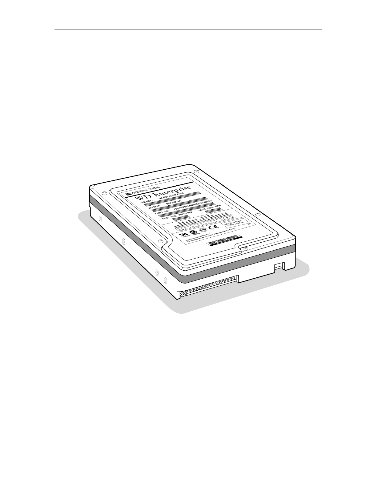
Designed to set a new direction in mass storage solutions, the WD Enterprise™ lowprofile 3.5-inch hard drives are the first in a family of 7200 RPM products. The
outstanding performance, capacity, and reliability of these mass storage solutions make
them the most competitive price/performance choice for workstations, servers, and
multi-user systems.
The WDE2170 and WDE4360 drives feature formatted capacities of 2.1 and 4.3
gigabytes with media data transfer rates up to 140 Mbits per second. These drives are
SCSI-3 SPI compliant and support Ultra Fast and Ultra Fast Wide host transfer rates of
up to 40 MB/s. Advanced read/write caching, command queuing, command reordering
(seek and rotational), Self Monitoring and Reporting Technology (S.M.A.R.T.) and
SCSI Configure Automatically (SCAM) are standard features on the Western Digital
Enterprise hard drives.
Western Digital hard drives are designed and manufactured to the highest standards of
quality and reliability. WD Enterprise drives incorporate the mechanical platform design
and proven recording technologies of Western Digital’s award-winning Caviar drives.
This quality design means the WD Enterprise drives have fewer disks and heads which
translates into many performance and reliability advantages. The WDE2170 and
WDE4360 drives deliver the performance, capacity, and reliability demanded by all high
performance enterprise systems.
4079-001045 Rev. B
RELEASED 04-08-97
1
Page 10
Description and Features WD Enterprise WDE2170/WDE4360
2
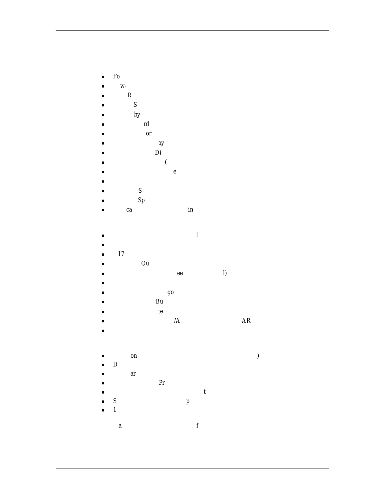
1.2. Advanced Features
Product Features
Formatted Capacities of 2.17 GB and 4.36 GB
Low-profile 1-Inch (25.4 mm) in Height
7200 RPM Spindle Speed
SCSI-3 SPI Compliant; Ultra Fast/Ultra Fast Wide with SCA-2 interface supported
512 kilobytes Programmable Multi-segmented Data Buffer (1 MB option)
Zoned Recording
Headerless Format
SCAM Plug-N-Play Compliant
Single-ended or Differential SCSI Drivers/Receivers (optional)
Active Termination (available on 50- and 68-pin single-ended drives)
Downloadable Firmware (both interface and servo code)
Embedded Servo
Balanced Spindle
Dynamic Spindle Brake
Vertical or Horizontal Mounting
Performance Features
Media Data Transfer Rate up to 140 Mbits/s
Average Read Seek Time of 8 ms
4.17 ms Rotational Latency
Command Queuing
Command Reordering (Seek and Rotational)
Write/Read Coalescing
Adaptive Caching Algorithm
Self-Optimizing Buffer Ratios
Adaptive Segmented Cache
Auto-Read Reallocation/Auto-Write Reallocation (ARRE/AWRE)
Adaptive Servo Functions
Reliability Features
Self Monitoring and Reporting Technology (S.M.A.R.T.)
Direct Hot-Plug Capability in SCA-2 Configuration
Hardware ECC On-The-Fly Error Correction
CRC Data Buffer Protection
Sector Slipping Defect Management
Self Diagnostics on Power Up
1,000,000 Hour MTBF Projected
These advanced product features are further defined in section 3. In certain cases we
refer you to other documents for additional detail. To obtain a document, contact your
local Western Digital sales office, authorized Western Digital reseller, or access the
Western Digital web page at
www.wdc.com
RELEASED 04-08-97
4079-001045 Rev. B
Page 11

WD Enterprise WDE2170/WDE4360 Description and Features
1.3. Options
Upon request, the following options are incorporated at the time of production.
Data Buffer of 1 Megabyte
The standard data buffer size is 512 kilobytes. You may order a 1 megabyte option.
For more details, refer to the interface matrix table in Appendix A.
Single-unit Shipping Pack Kit
The drive is shipped in bulk packaging to provide maximum protection against
damage during transit. Units shipped individually require additional protection as
provided by the single-unit shipping pack. Contact your local Western Digital sales
office for ordering information.
Differential SCSI
The WD Enterprise drive provides, as an option, differential SCSI drivers/receivers
on the 68-pin interface configuration. For more details, refer to the interface matrix
table in Appendix A.
Termination Power
50-pin and 68-pin drives have the ability to supply termination power to the SCSI
bus. This option can be enabled by setting the corresponding jumper on the option
block.
4079-001045 Rev. B
RELEASED 04-08-97
3
Page 12

Specifications WD Enterprise WDE2170/WDE4360
2. S
2.1. Performance Specifications
PECIFICATIONS
Table 2-1. WDE2170/4360 Performance Specifications
PERFORMANCE CRITERIA WDE2170/WDE4360 SPECIFICATIONS
Average Seek
Read
•
Write
•
Track-to-Track Seek
Read
•
Write
•
Full Stroke Seek < 18 ms
Average Latency 4.17 ms
Rotational Speed 7200 RPM
Data Transfer Rate
Media to Buffer
•
Buffer to Host
•
Buffer Size
Error Rate - Unrecoverable < 1 in 1014 bits read
Spindle Start Time < 30s to ready
Spindle Stop Time < 20s
Contact Start/Stop Cycles (CSS)
1
User can access the entire 512 KB or 1 MB data buffer.
2
Must not exceed defined environmental specification.
1
2
Note: This table represents typical values under nominal conditions.
8 ms
9.5 ms
1 ms
2.5 ms
81-140 Mbits/s
40 MB/s max.
512 KB
1 MB optional
20,000
4
RELEASED 04-08-97
4079-001045 Rev. B
Page 13

WD Enterprise WDE2170/WDE4360 Specifications
2.2. Physical Specifications
Table 2-2. WDE2170/4360 Physical Specifications
Physical Specifications WDE2170 WDE4360
Formatted Capacity
Interface(s) Ultra Fast
Actuator Type Rotary Voice Coil Rotary Voice Coil
Media Type Thin Film Thin Film
Head Type Thin Film Inductive Thin Film Inductive
Servo Type Embedded Embedded
Number of Disks 2 4
Number of Data Surfaces 4 8
Number of Heads 4 8
Bytes per Sector
Tracks per Inch 6150 6150
Bits per Inch (000) 125 (ID) 125 (ID)
Areal Density 769 Mb/in
Total Cylinders 5956 5956
Zones per Surface 20 20
User Sectors per Drive (512 byte) 225 (OD), 133 (ID) 225 (OD), 133 (ID)
Recording Method 0,4,4 RLL
5
ECC
1
Western Digital defines a megabyte (MB) as 1,000,000 bytes and a gigabyte (GB) as
1,000,000,000 bytes.
2
Differential option available on 68-pin models.
3
The standard is 512 byte sectors. Optionally, we will support 512-528 bytes per sector
in even byte increments. Capacity will change depending on sector size chosen.
4
Run Length Limited
5
ECC has 144-bit span in hardware for correction on-the-fly.
1
2170 MB 4360 MB
Ultra Fast
• (50-pin)
Ultra Fast Wide
• (68-pin)
2
• (80-pin SCA-2)
3
512 512
2
4
• (50-pin)
Ultra Fast Wide
• (68-pin)
• (80-pin SCA-2)
769 Mb/in
0,4,4 RLL
2
2
144-bit Reed Solomon 144-bit Reed Solomon
4079-001045 Rev. B
RELEASED 04-08-97
5
Page 14

Specifications WD Enterprise WDE2170/WDE4360
2.2.1. Physical Dimensions
Table 2-3. WDE2170/4360 Physical Dimensions
Physical U.S. Metric
Characteristic Dimension Tolerance Dimension Tolerance
Height 1.00 inch ± 0.02 inch 25.4 mm ± 0.51 mm
Length 5.75 inches ± 0.02 inch 146.05 mm ± 0.51 mm
Width 4.00 inches ± 0.02 inch 101.6 mm ± 0.51 mm
Weight WDE2170 1.1 pounds ± 0.11 lbs. 0.48 kg ± 0.05 kg
Weight WDE4360 1.2 pounds ± 0.11 lbs. 0.53 kg ± 0.05 kg
6
RELEASED 04-08-97
4079-001045 Rev. B
Page 15
WD Enterprise WDE2170/WDE4360 Specifications
2.3. Mechanical Specifications
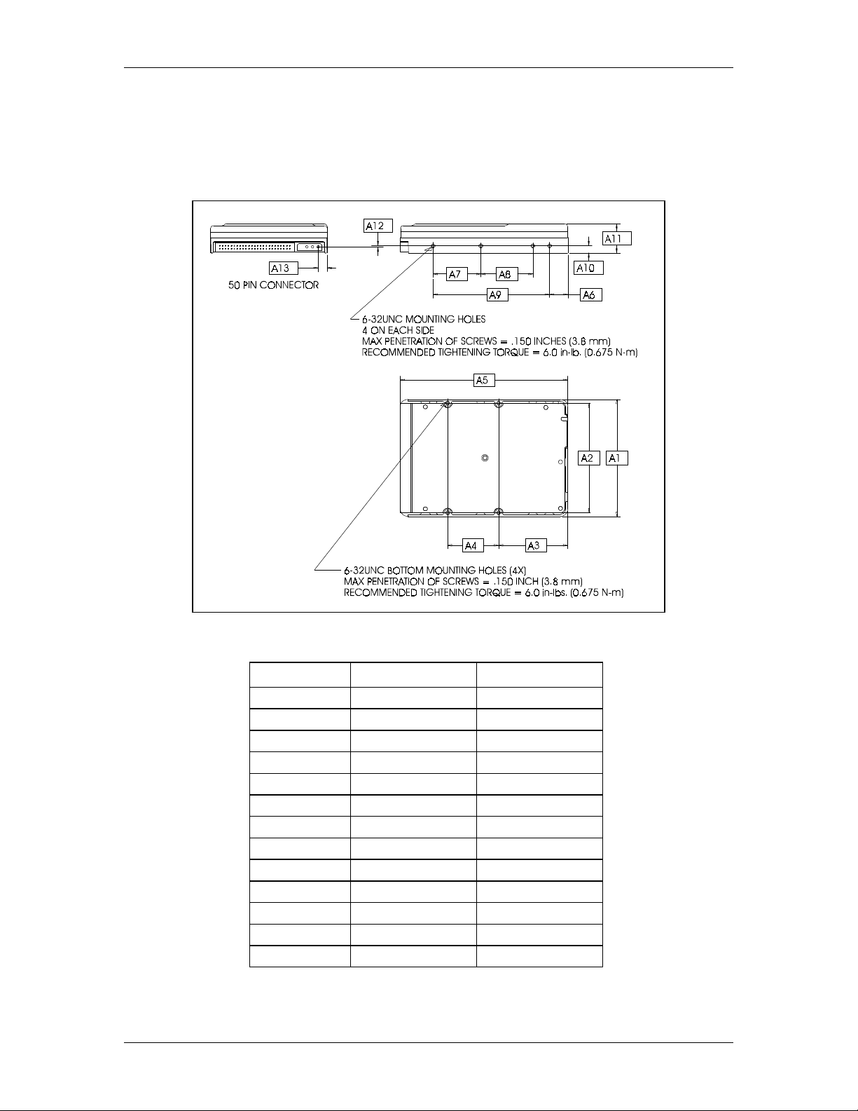
Figure 2-1 through Figure 2-3 show the mounting dimensions and locations of the screw
holes for the WDE2170 and WDE4360 drives.
Figure 2-1. 50-pin Drive Dimensions
4079-001045 Rev. B
Table 2-4. 50-pin Drive Dimensions
Dimension Inches Millimeters
A1
A2
A3
A4
A5
A6
A7
A8
A9
A10
A11
A12
A13
4.000 ± .020 101.60 ± 0.51
3.750 ± .010 95.25 ± 0.25
2.375 ± .010 60.32 ± 0.25
1.750 ± .010 44.45 ± 0.25
5.750 ± .020 146.05 ± 0.51
.625 ± .020 15.87 ± 0.51
1.638 ± .010 41.60 ± 0.25
1.787 ± .010 45.39 ± 0.25
4.000 ± .010 101.60 ± 0.25
.250 ± .010 6.35 ± 0.25
1.000 ± .020 25.40 ± 0.51
.035 ± .020 0.89 ± 0.51
.300 ± .020 7.62 ± 0.51
RELEASED 04-08-97
7
Page 16
Specifications WD Enterprise WDE2170/WDE4360
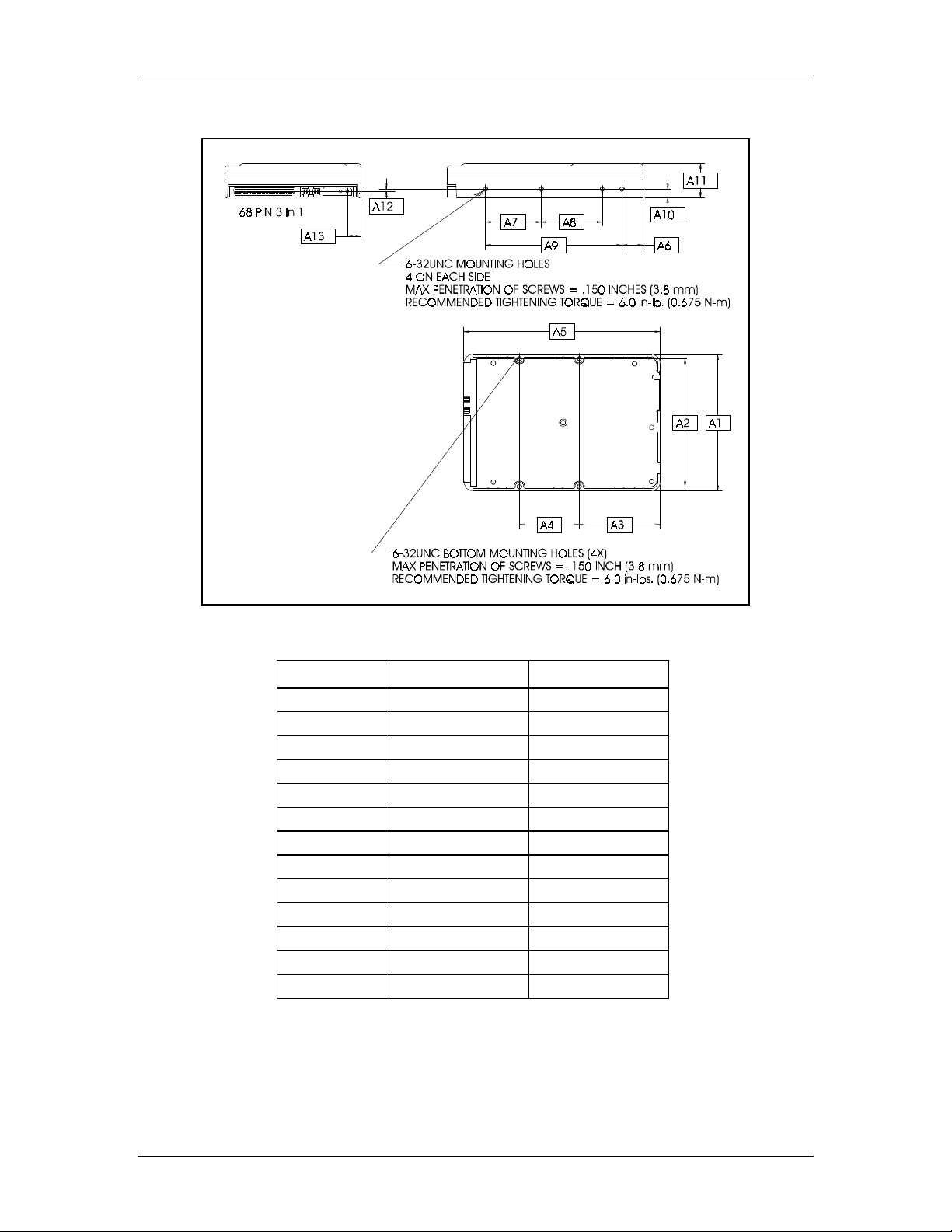
Figure 2-2. 68-pin Drive Dimensions
Table 2-5. 68-pin Drive Dimensions
Dimension Inches Millimeters
A1
A2
A3
A4
A5
A6
A7
A8
A9
A10
A11
A12
A13
4.000 ± .020 101.60 ± 0.51
3.750 ± .010 95.25 ± 0.25
2.375 ± .010 60.32 ± 0.25
1.750 ± .010 44.45 ± 0.25
5.750 ± .020 146.05 ± 0.51
.625 ± .020 15.87 ± 0.51
1.638 ± .010 41.60 ± 0.25
1.787 ± .010 45.39 ± 0.25
4.000 ± .010 101.60 ± 0.25
.250 ± .010 6.35 ± 0.25
1.000 ± .020 25.40 ± 0.51
.067 ± .020 1.70 ± 0.51
.410 ± .020 10.41 ± 0.51
8
RELEASED 04-08-97
4079-001045 Rev. B
Page 17
WD Enterprise WDE2170/WDE4360 Specifications
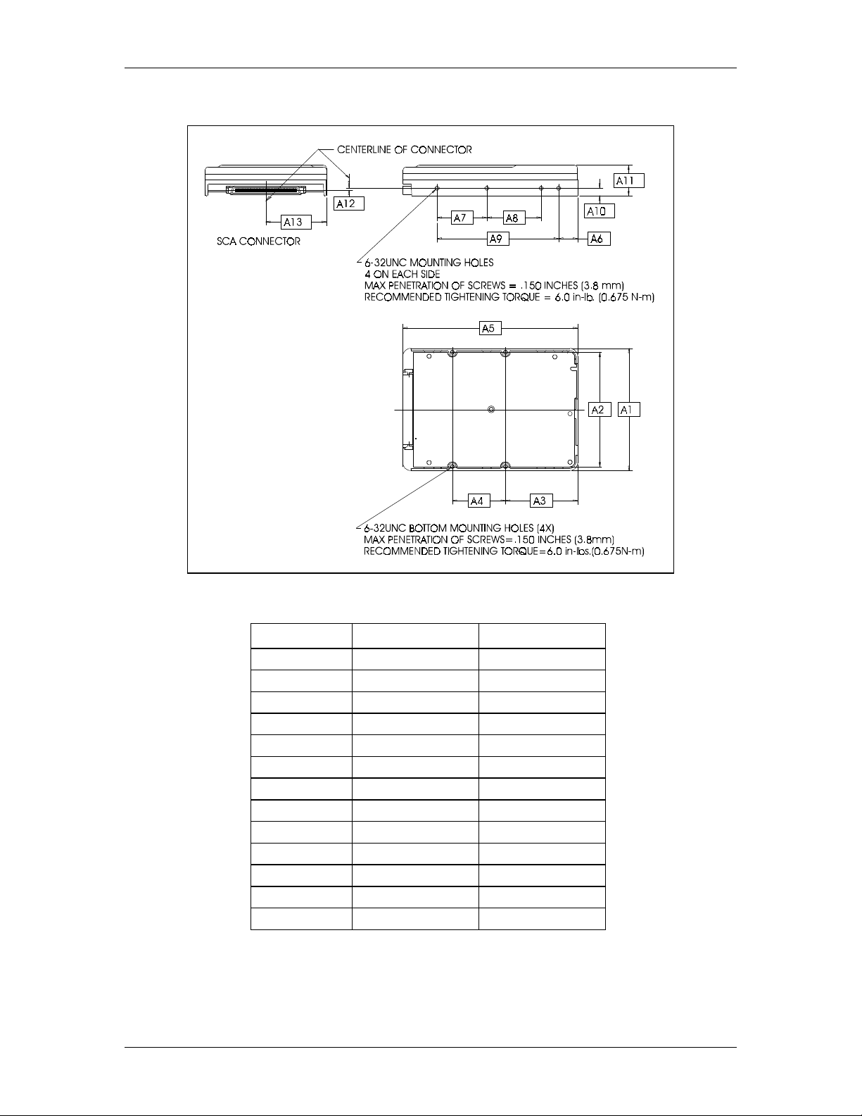
Figure 2-3. 80-pin Drive Dimensions
Table 2-6. 80-pin Drive Dimensions
Dimension Inches Millimeters
A1
A2
A3
A4
A5
A6
A7
A8
A9
A10
A11
A12
A13
4.000 ± .020 101.60 ± 0.51
3.750 ± .010 95.25 ± 0.25
2.375 ± .010 60.32 ± 0.25
1.750 ± .010 44.45 ± 0.25
5.750 ± .020 146.05 ± 0.51
.625 ± .020 15.87 ± 0.51
1.638 ± .010 41.60 ± 0.25
1.787 ± .010 45.39 ± 0.25
4.000 ± .010 101.60 ± 0.25
.250 ± .010 6.35 ± 0.25
1.000 ± .020 25.40 ± 0.51
.069 ± .020 1.75 ± 0.51
2.000 ± .020 50.80 ± 0.51
4079-001045 Rev. B
RELEASED 04-08-97
9
Page 18

Specifications WD Enterprise WDE2170/WDE4360
2.3.1. Mounting
The WD Enterprise drives feature side and bottom mounting holes, which allow the
drive to be mounted in any orientation. See Figure 2-4 for orientation axes.
The hard drive is a precision mechanical assembly. Improper mounting may distort the
drive frame and impair its ability to function. For instructions on installing the drive,
including drive handling and mounting, refer to the WD Enterprise Installation Guide
(document number 4079-001046).
Figure 2-4. Drive Axis Definition
10
RELEASED 04-08-97
4079-001045 Rev. B
Page 19

WD Enterprise WDE2170/WDE4360 Specifications
2.4. Electrical Specifications
2.4.1. Current Requirements and Power Dissipation
Table 2-7. WDE2170 Current Requirements and Power Dissipation
Operating
Mode
Population Mean + 4 Sigma
12 VDC
Spin-up
Seek
50 ops/s
2
Idle
Read/Write
Notes:
All values at 25°C, 5.0V, 12.0V input.
1
Example of doing 50 random ops/sec.
2
The idle condition is defined by the motor running at the full rated RPM with no seeking or read/write
peak DC
mean DC
1
390 mA
255 mA 625/785 mA 210 mA 570/760 mA 5.96/6.85 W 5.35/6.29 W
3
365 mA 645/795 mA 325 mA 585/770 mA 7.65/8.70 W 7.05/8.14 W
1.22A
Current
635/780 mA
645/795 mA
5 VDC
SE/Diff.
4
Current
Population Mean
12 VDC
peak DC
1.15A
mean DC
345 mA
Power
Pop Mean + 4 Sigma
5 VDC
4
SE/Diff.
580/760 mA
4
SE/Diff.
___ ___
585/770 mA 7.65/8.70 W 7.05/8.14 W
operations being performed. The drive was track following on the OD cylinder for these
measurements.
3
This is for a ratio of four reads per one write.
4
Differential option available on 68-pin models only.
Table 2-8. WDE4360 Current Requirements and Power Dissipation
Operating
Mode
Population Mean + 4 Sigma
12 VDC
Spin-up
Seek
50 ops/s
2
Idle
Read/Write
Notes:
All values at 25°C, 5.0V, 12.0V input.
1
Example of doing 50 random ops/sec.
2
The idle condition is defined by the motor running at the full rated RPM with no seeking or read/write
peak DC
mean DC
1
520 mA
390 mA 610/790 mA 350 mA 585/730 mA 7.60/8.40 W 7.06/7.80 W
3
500 mA 625/790 mA 460 mA 600/735 mA 9.22/9.95 W 8.71/9.38 W
operations being performed. The drive was track following on the OD cylinder for these
measurements.
3
This is for a ratio of four reads per one write.
4
Differential option available on 68-pin models only.
1.24A
Current
625/790 mA
625/790 mA
5 VDC
SE/Diff.
Current
Population Mean
12 VDC
4
peak DC
1.16A
mean C
480 mA
5 VDC
4
SE/Diff.
595/725 mA
600/735 mA 9.22/9.95 W 8.71/9.38 W
Power
Pop Mean + 4 Sigma
4
SE/Diff.
___ ___
Power
Population Mean
4
SE/Diff.
Power
Population Mean
4
SE/Diff.
4079-001045 Rev. B
RELEASED 04-08-97
11
Page 20

Specifications WD Enterprise WDE2170/WDE4360
2.4.2. 12V Current Profile
The following graphs show the +12V current profile for the WDE2170 and WDE4360
drives during spin-up and run.
Figure 2-5. WDE2170 +12V Current Profile
CURRENT (Amps)
1.6
1.4
1.2
1.0
0.8
0.6
0.4
0.2
0
0 1 2 3 4 5 6 7 8 9 1 0
TIM E (Second s)
WDE2170
Figure 2-6. WDE4360 +12V Current Profile
1.6
1.4
1.2
Spinup Peak AC Current
Spinup Peak DC Current
CURRENT (Amps)
12
1.0
0.8
0.6
0.4
0.2
0
0 1 2 3 4 5 6 7 8 9 1 0
TIME (Secon ds)
WDE4360
RELEASED 04-08-97
4079-001045 Rev. B
Page 21

WD Enterprise WDE2170/WDE4360 Specifications
3
2.4.3. Input Voltage Requirements
The input voltage requirements for the WDE2170 and WDE4360 are as follows:
+ 5V ± 5% and + 12V ± 5%
2.4.4. Ripple
Table 2-9. Voltage Ripple
+12 VDC +5 VDC
Maximum Start: 400 mV (peak-to-peak)
Run: 150 mV (peak-to-peak)
Frequency 0-20 MHz 0-20 MHz
100 mV (peak-to-peak)
2.4.5. Bring-Up Sequence
After power is applied, the following events occur as the drive becomes ready for use.
Note: Typical spindle start time appears in Table 2-1.
1. The microprocessor tests itself, the on-board memory, and components on the
printed circuit board assembly (PCBA).
2. The SCSI interface is enabled to accept the following commands: Inquiry, Request
Sense, Start/Stop Unit, Test Unit Ready. Refer to the Western Digital SCSI
Implementation Guide (document number 4096-001116) for additionally supported
SCSI commands and features.
3. Internal electronic component initialization and testing continues.
4. If the Auto Start option is enabled, the motor spins up.
5. The servo system calibrates itself.
6. Additional configuration information is read from an area on the disk that is
reserved for the drive’s internal use.
7. A self test is performed on the read/write path.
8. The drive is ready to read and write data.
If an error occurs during the bring-up sequence, sense data is available if the SCSI
interface is working; otherwise the LED, if installed, flashes.
If a reassign was in progress when the drive was turned off, the drive automatically
completes that operation during startup.
4079-001045 Rev. B
RELEASED 04-08-97
1
Page 22

Specifications WD Enterprise WDE2170/WDE4360
2.5. Environmental Specifications
2.5.1. Shock and Vibration
All shock and vibration specifications apply to the mounting and orientation conditions
described in section 2.3. Orientation axes are defined in Figure 2-4.
Table 2-10. Shock and Vibration
Shock
Operating 10G (2 per second maximum)
Non-operating 70G (3 drops per axis maximum)
Non-operating Rotational Shock 10,000 rad/s
Note:
Half-sine wave of 3 ms duration without non-recoverable errors.
Vibration
Operating 5-20 Hz, 0.037 inch (peak to peak)
Non-operating 5-20 Hz, 0.098 inch (peak to peak)
Sweep Rate One octave per minute (minimum)
20-400 Hz, 0.75G (0 to peak)
20-400 Hz, 2.0G (0 to peak)
2
Operating Shock
WD Enterprise drives are tested by applying a linear shock in each axis, one axis at a
time, at a rate not exceeding two shocks per second.
The drive incurs no physical damage and no hard errors while subjected to intermittent
shock not exceeding the level listed in Table 2-10. Operating performance may degrade
during periods of shock application.
Non-operating Shock
WD Enterprise drives are tested by applying a linear shock in each axis, one axis at a
time. A maximum of three shocks per axis is applied.
The drive incurs no physical damage when subjected to non-repetitive shocks not
exceeding the level listed in Table 2-10.
Non-operating Rotational Shock
WD Enterprise drives are tested by applying a rotational shock in each direction, about
each axis, one axis at a time.
The drive incurs no physical damage when subjected to rotational shocks not exceeding
the level listed in Table 2-10.
14
RELEASED 04-08-97
4079-001045 Rev. B
Page 23

WD Enterprise WDE2170/WDE4360 Specifications
5
Operating Vibration
WD Enterprise drives are tested by applying a continuous swept sine excitation in each
linear axis, one axis at a time. Sweep rate is one octave per minute.
The drive incurs no physical damage and no hard errors while subjected to continuous
vibration not exceeding the level listed in Table 2-10. Operating performance may
degrade during periods of vibration application.
Non-operating Vibration
Note: This specification applies to handling and transportation of unmounted drives.
Drives are tested by applying a continuous swept sine excitation in each linear axis, one
axis at a time. Sweep rate is one octave per minute.
The drive incurs no physical damage when subjected to continuous vibration not
exceeding the level listed in Table 2-10.
Packaged Shock and Vibration
The shipping packaging is designed to meet the National/International Safe Transit
Association (N/ISTA) standards for packaged products.
The drive incurs no physical damage when subjected to the N/ISTA standards.
4079-001045 Rev. B
RELEASED 04-08-97
1
Page 24

Specifications WD Enterprise WDE2170/WDE4360
2.5.2. Temperature and Humidity
Table 2-11. Temperature and Humidity
Temperature and Humidity
Operating
Temperature
Humidity
Thermal Gradient
Non-Operating
Temperature
Humidity
Thermal Gradient
1
The system environment must provide sufficient air flow to limit maximum
surface temperatures as defined in Table 2-12.
1
5°C to 55°C (41°F to 131°F)
10-90% RH non-condensing
33°C (maximum wet bulb)
10°C/hour (maximum)
-40°C to 60°C (-40°F to 140°F)
5-95% RH non-condensing
33°C (maximum wet bulb)
20°C/hour (maximum)
2.5.3. Cooling
Drive component temperatures must remain within the limits specified in Table 2-12.
Figure 2-7 and Figure 2-8 show the temperature measurement locations. Sustained
operation at temperatures in excess of the reliability values degrades the MTBF rating.
Short excursions up to, but not exceeding, the maximum values do not affect the MTBF
rating. Maximum component temperature ratings must not be exceeded under any
operating condition. The drive may require forced air cooling to meet specified
operating temperatures.
Table 2-12. Maximum & Reliability Operating Temperature Limits
Component Location Maximum Reliability
Drive Baseplate #1, Figure 2-7.
4915 #2, Figure 2-8.
64C96 #3, Figure 2-8.
2298 #4, Figure 2-8.
1501 #5, Figure 2-8.
1
Sustained operation at temperatures in excess of the reliability values degrades the MTBF
rating.
65°C (149°F) 55°C (131°F)
95°C (203°F) 80°C (176°F)
80°C (176°F) 65°C (149°F)
80°C (176°F) 65°C (149°F)
85°C (185°F) 70°C (158°F)
1
16
RELEASED 04-08-97
4079-001045 Rev. B
Page 25

WD Enterprise WDE2170/WDE4360 Specifications
7
2.5.4. Atmospheric Pressure
Table 2-13. Allowable Altitude Ranges
Altitude
Operating -1,000 feet to 10,000 feet (-300m to 3,000m)
Non-operating -1,000 feet to 40,000 feet (-300m to 12,000m)
2.5.5. Acoustics
Table 2-14. Sound Power Level
Mode Typical Maximum
Idle 4.0 A-weighted Bels 4.3 A-weighted Bels
Seek 5.0 A-weighted Bels 5.3 A-weighted Bels
Notes:
1. Sound power is measured in accordance with ECMA-74 and ISO 7779.
Seek mode sound power is measured while the drive performs random
seeks at a rate of 33 seeks/sec.
2. Drives are tested after a 20 minute warm up period.
4079-001045 Rev. B
RELEASED 04-08-97
1
Page 26

Specifications WD Enterprise WDE2170/WDE4360
Figure 2-7. Drive Baseplate Thermocouple Location
18
RELEASED 04-08-97
4079-001045 Rev. B
Page 27

WD Enterprise WDE2170/WDE4360 Specifications
9
Figure 2-8. PCBA Thermocouple Locations
4079-001045 Rev. B
RELEASED 04-08-97
1
Page 28

Specifications WD Enterprise WDE2170/WDE4360
2
2.6. Reliability Specifications
Table 2-15. WDE2170 and WDE4360 Reliability Parameters
Recoverable Data Error Rate: Less than 10 in 1011 bits read
Unrecoverable Data Error Rate: Less than 1 in 1014 bits read
Miscorrected Data Error Rate: Less than 1 in 1021 bits read
Seek Error Rate: Less than 10 in 108 seeks (average)
Projected MTBF: 1,000,000 hours
Service Life: 5 years
Preventive Maintenance: None required
Note:
The error rates listed above reflect the drive operating under specified conditions.
2.7. Agency Approvals
2.7.1. Product Safety
Western Digital drives are free of Polychlorinated Biphenyl (PCBs) and Cadmium
materials. In addition, prohibited Chlorofluorocarbons (CFCs) are not used in the
manufacturing process.
Models WDE2170 and WDE4360 meet the safety standards of the following regulatory
agencies:
Underwriters Laboratories:
UL-Standard 1950, Standard for Safety of
Information Technology Equipment including Electrical Business Equipment (File
E101559)
Canadian Standards Association:
CSA-Standard C22.2, No. 950-M89, Standard
for Safety of Information Technology Equipment including Electrical Business
Equipment (File LR68850)
TUV Essen Laboratories:
IEC-950 (EN60950) Standard for Safety of Information
Technology Equipment including Electrical Business Equipment
2.7.2. Electromagnetic Compatibility (EMC)
Upon request, Western Digital provides technical information pertaining to compliance
testing of the following:
Federal Communication Commission (FCC):
for Radiated and Conducted Emission, Part 15, Subpart B, for Class B Equipment
CE Compliance for Europe:
Verified to comply with EN55022 for RF Emissions
and EN50082-1 for Generic Immunity as applicable
VDE:
VDE 0871/6.78, BZT Class B, Radio Frequency Interference of Radio
Frequency Equipment for Industrial, Scientific, and Medical (ISM) and similar
purposes
VCCI:
VCCI Class 2-CISPR Class B, Radiated and Line Conducted Emissions
Verified to comply with FCC Rules
0
RELEASED 04-08-97
4079-001045 Rev. B
Page 29

WD Enterprise WDE2170/WDE4360 Advanced Product Features
2
3. A
3.1. Compatibility Testing
3.2. SCSI-3 SPI Compliant
3.3. Embedded Servo Control
DVANCED PRODUCT FEATURES
Western Digital performs extensive testing in its Functional Integrity Test Lab (FIT
Lab™). By equipping the FIT Lab with multiple host systems, adapters, operating
systems, and application programs, compatibility is achieved with a broad range of
applications implemented on workstations, servers, multi-user, and array systems.
Drive models WDE2170 and WDE4360 conform to the SCSI-3 SPI (SCSI Parallel
Interface) standard. The drives also support the Ultra SCSI performance specification
and are offered in several configurations, such as Ultra Fast (8-bit, 50-pin; up to
20MB/s) and Ultra Fast Wide (16-bit, 68-pin, 80-pin SCA-2; up to 40MB/s) host
transfer rates.
The WD Enterprise drives feature embedded servo technology to generate accurate
position information on every track. An embedded servo system has servo bursts
interspersed with customer data on every track. This provides a tight coupling between
head positioning and customer data – a necessity for good soft error rates. In addition,
embedded servo technology is less susceptible to thermal shifts of the system since
customer data and position information are recorded together on the same track.
3.4. Read Caching and Pre-Fetch
Read caching allows the drive to maintain data in the cache for quick transfer to the host
when a media access is not required. Pre-fetching takes place after a media access when
the drive reads data into the cache that the firmware determines as likely to be requested
by the host. Refer to the Western Digital SCSI Implementation Guide (document number
4096-001116) for further details.
3.5. Write Caching
Write caching gives the host the ability to allow the drive to asynchronously write data
to the media while other processes may occur. Refer to the Western Digital SCSI
Implementation Guide (document number 4096-001116) for further details.
3.6. 512 Kilobyte Data Buffer
The entire data buffer is user accessible, enabling powerful data caching capabilities.
3.7. Adaptive Caching
The drives are equipped with an adaptive caching capability which enables them to
improve performance and throughput based on how the drive is being used. Each drive
determines the environment in which it is being used and optimizes the way it handles
commands and data.
4079-001045 Rev. B
RELEASED 04-08-97
1
Page 30

Advanced Product Features WD Enterprise WDE2170/WDE4360
2
3.8. Command Queuing and Reordering
The drives support both tagged and untagged queuing. Tagged queuing allows the drive
to receive multiple I/O processes from each initiator. Untagged queuing allows the drive
to receive a maximum of one I/O process from each initiator.
In order to use tagged command queuing, the initiator must set the disconnect privilege
bit. This allows the drive to disconnect from the SCSI bus. It also allows the same or
other initiators to connect to the drive and send additional commands. The drive returns
a status of BUSY if the disconnect privilege bit is off and the drive has I/O processes in
the command queue. The drive has the capability to queue up to 64 I/O processes. Upon
receipt of the 65th I/O process, the drive returns a status of QUEUE FULL.
The drive can reorder I/O processes in the command queue. The order in which the
drive executes I/O processes may differ from the order in which they were received.
Command reordering employs an algorithm which improves the throughput of the drive
by attempting to minimize both the seek time and the rotational latency.
The drive uses a command aging feature to prevent the command reordering algorithm
from keeping I/O processes waiting in the command queue for extended periods of time.
The drive allows I/O processes to wait in the command queue for only a specified length
of time before they are scheduled in the next I/O process.
3.9. Media Defect Management
Western Digital drives support a defect management algorithm that uses sector slipping.
Defective sites are pushed down during a reassignment operation to maintain a
sequential order. Spare sectors are placed throughout the drive to support this algorithm.
This routine can be invoked by the drive when Auto-Read Reallocation/Auto-Write
Reallocation (ARRE/AWRE) is enabled in MODE SELECT Page 1. If these functions
are disabled, the drive reports status and may recommend that the host request a
reassign.
3.10. Microcode Download
Western Digital drives support downloadable microcode via the SCSI WRITE BUFFER
command. The supported modes include Download Microcode and Save, as well as
Download Microcode with Offsets and Save. Download Microcode with Offsets is used
when the buffer is limited to the full download and requires smaller partial downloads to
complete the download task.
3.11. Reed Solomon ECC On-the-Fly
Error Correction Code (ECC) on-the-fly is a correction technique that reduces the
uncorrectable read error rate in hardware. This provides a high degree of data integrity
with no impact on the drive’s performance.
3.12. CRC Data Protection
Cyclic Redundancy Check (CRC) data protection is a feature that enhances data
integrity. During a write operation, before a user data block enters the cache (data
buffer), the SCSI controller generates CRC data (2 bytes) and attaches it to the user data
block (usually 512 bytes). During a read operation, the SCSI controller reads each user
data block and its CRC data in the cache, then verifies the CRC data as it transfers each
user data block to the SCSI bus.
2
RELEASED 04-08-97
4079-001045 Rev. B
Page 31

WD Enterprise WDE2170/WDE4360 Advanced Product Features
23
3.13. Zoned Recording
The drives employ zoned recording to increase data density on the outer tracks of the
drive. Zoned recording allows the adjustment of the number of sectors per track, which
provides storage of more sectors on the larger, outer tracks. Formatting packs data
uniformly throughout the surface of the platter by dividing the outer tracks into more
sectors. With more bytes per track, the drive reads the data in the outer zones at a faster
rate.
3.14. Headerless Format
Headerless format is also known as ID-less or No-ID sector format. This format removes
the header (or ID fields) and all the information within the header (track format) to
provide a dramatic increase in user capacity. Our advanced, integrated SCSI controller
assumes the task of determining the physical location of each sector.
3.15. LED Support
If an LED is installed on the drive, the following occurs:
The LED is turned off as soon as power is applied. If Auto Start is enabled, the LED
is on while the drive is spinning up and turned off when Auto Start is completed.
The LED is on when a SCSI command is being executed.
The LED flashes when an error prohibits the use of the SCSI interface.
4079-001045 Rev. B
RELEASED 04-08-97
Page 32

Advanced Product Features WD Enterprise WDE2170/WDE4360
2
3.16. Option Block Functions
The firmware uses several pins on the option block to modify the drive characteristics.
The definitions for the jumpers follow:
SCSI ID:
Disable Auto Start:
not spin-up until a START UNIT command is issued. Without this jumper, the
drive will spin-up and prepare itself at power on without having to receive a
START UNIT command.
Auto Start Delay:
The delay time equals the SCSI ID multiplied by 4 seconds.
Disable Target Initiated Synchronous/Wide Negotiation:
dictates that the drive cannot initiate either synchronous negotiation or wide
negotiation. Without this jumper the drive will initiate synchronous and wide
negotiation when appropriate.
Disable Unit Attention:
reported following a Power On or Reset sequence. A REQUEST SENSE command
following one of those conditions still yields the correct sense data for the UNIT
ATTENTION condition, as sense data is generated regardless of the jumper setting.
A jumper on this pin disables the generation of a CHECK CONDITION for the
Power On and Reset UNIT ATTENTION conditions. With no jumper attached, a
CHECK CONDITION status is reported in these situations.
SCSI Configure Automagically (SCAM):
compliant, which eases user configuration of SCSI IDs and allows for hot plugging
on single and multiple drive systems. Use of this jumper allows the drive to function
as a SCAM level 2 device. Without the jumper the drive is not a SCAM device.
Active SCSI Termination:
be properly terminated. Use of this jumper enables active termination on the drive.
Without this jumper, active termination is disabled.
Four jumpers are used to identify the default SCSI ID for the drive.
Use of this jumper disables Auto Start, meaning the drive does
Use of this jumper allows the Auto Start to incorporate a delay.
Use of this jumper
This controls whether a CHECK CONDITION status is
The drive is SCAM levels 1 and 2
To ensure reliable communication, the SCSI bus must
Note: For more information on the option block, refer to section 5.
4
RELEASED 04-08-97
4079-001045 Rev. B
Page 33

WD Enterprise WDE2170/WDE4360 Advanced Product Features
25
3.17. Error Recovery Operations
Error recovery options are set using MODE SELECT Page 1 (Read/Write Error
Recovery Page) and the Write Recovery Threshold and Read Recovery Threshold fields
in MODE SELECT Page 0 (WD Vendor Unique Page).
The drive employs a variety of recovery actions based on the type of error that occurs.
Separate recovery actions are defined for read errors, write errors, servo errors, and
drive fault errors. For a given error type, several different recovery actions may be used.
For example, read error recovery may use retries, servo track offsets, channel parameter
modification, and software ECC in an attempt to recover the error. Error information is
available to the host via the REQUEST SENSE command based on the settings in
MODE SELECT Pages 0 and 1.
The drive uses a 3-way interleaved Reed-Solomon ECC operating on 8 bit (1 byte)
symbols. On-the-fly ECC is capable of correcting single burst errors up to 1 byte per
interleave (24 bits total) with no performance degradation. On-the-fly correction is done
in hardware and cannot be disabled. The drive firmware also implements a software
ECC, which is capable of correcting single or double burst errors up to 2 bytes per
interleave.
Refer to the Western Digital SCSI Implementation Guide (document number 4096-
001116) for more information.
3.18. Self-Monitoring, Analysis, and Reporting Technology
(S.M.A.R.T.)
Self-Monitoring, Analysis and Reporting Technology (S.M.A.R.T.) is a hard drive
firmware technology that performs drive failure prediction by monitoring selected
parameters during normal drive operations. The intent of this technology is to minimize
unscheduled system downtime caused by predictable drive failures. By monitoring
selected parameters, the S.M.A.R.T. firmware can predict some drive failures before
they actually occur, allowing the user to schedule drive replacement and minimize
system interruptions.
Refer to the Western Digital SCSI Implementation Guide (document number 4096-
001116) for more information.
4079-001045 Rev. B
RELEASED 04-08-97
Page 34

Advanced Product Features WD Enterprise WDE2170/WDE4360
2
3.19. Hot Plug/Unplug Support
The conditions for hot-plugging drives into an active SCSI bus follow:
The drive signal ground must be made before the SCSI bus signals.
Power—both +5V and +12V—cannot be applied until the SCSI bus signals are
connected.
The host(s) are not actively trying to access the inserted device.
The drive is not supplying TERMPWR to the SCSI bus.
The drive is not supplying termination to the SCSI bus.
The conditions for the removal of a device from an active SCSI bus follow:
The host(s) are not actively trying to access the device to be removed.
The drive is not supplying TERMPWR to the SCSI bus.
The drive is not supplying termination to the SCSI bus.
Power, both +5V and +12V must be removed before the SCSI bus signals are
disconnected.
The drive signal ground must be broken after the SCSI bus signals.
The SCA-2 (80-pin) connector allows for proper insertion and extraction by providing
an appropriate mechanical mating that makes the signal ground connection first upon
insertion and last upon extraction. There are also control signals that allow the proper
application of power to adhere to the insertion and extraction rules above. However, the
user must guarantee that the three rules listed below apply:
The host(s) are not actively trying to access the inserted device.
The drive is not supplying TERMPWR to the SCSI bus.
The drive is not supplying termination to the SCSI bus.
6
RELEASED 04-08-97
4079-001045 Rev. B
Page 35

WD Enterprise WDE2170/WDE4360 SCSI Interface and Command Set
27
4. SCSI I
Refer to the Western Digital SCSI Implementation Guide (document number 4096-001116).
NTERFACE AND COMMAND SET
4079-001045 Rev. B
RELEASED 04-08-97
Page 36

The Option Block WD Enterprise WDE2170/WDE4360
2
5. T
HE OPTION BLOCK
The WD Enterprise drive PCBA contains an option block that controls the drive’s operation.
This block is equipped with jumper pins that correspond to various options controlled by SCSI
commands. Jumpers are used to enable or disable the options and modify the drive configuration.
The user-configurable jumpers appear in Table 5-1.
Note: Jumpers should only be changed when the drive is powered down.
5.1. Physical Characteristics
The block consists of a 2-pin by 17-pin male header. Pin-to-pin spacing is 2 mm by 2
mm.
5.2. Pin Designation
The pin layout appears below. The diagram represents the view as seen by the customer.
Figure 5-1. Option Block and LED Pin Designation
ANODE
2
CATHODE
1
8
RELEASED 04-08-97
4079-001045 Rev. B
Page 37

WD Enterprise WDE2170/WDE4360 The Option Block
29
5.3. Option Block Pin Assignments
The option block is used to modify the drive characteristics. The table below shows the
pin numbers that correspond to each option or signal, and provides instruction for
enabling and disabling these features. Refer to the WD Enterprise Installation Guide
(document number 4079-001046) for option definitions.
Table 5-1. Option Block Pin Assignments
OPTION/SIGNAL PINS CONFIGURATION NOTES
SCSI IDs 1 - 8 Set according to Table 5-2.
(KEY)/LED- X - 10 X - no pin/10 - LED cathode connection
RESERVED 11 - 12 11 - Ground/12 - Reserved
OPT 1: DISABLE AUTO START 13 - 14 Install jumper to disable auto start.
OPT 2: AUTO START DELAY 15 - 16 Install jumper to enable auto start delay.
OPT 3: SCAM 17 - 18 Install jumper to enable SCAM.
OPT 4: DISABLE UNIT ATTENTION 19 - 20 Install jumper to disable unit attention.
OPT 5: DISABLE TARGET INITIATED
SYNCHRONOUS/WIDE NEGOTIATION
OPT 6: SCSI TERMINATION 23 - 24 Install jumper to enable SCSI termination.
TXD/RXD 25 - 26 Reserved
TPWR/+5V 27 - 28
LED+/+5V 29 - 30 29 - LED anode connection/30 - Reserved
+12R/+12R 31 - 32 Reserved
+12V/+12V 33 - 34 Reserved
Note:
Pins 1,3,5,7,11,13,15,17,19,21, and 23 are ground.
21 - 22
Install jumper to disable target initiated
synchronous/wide negotiation.
Install jumper to enable TERMPWR on the
SCSI bus.
4079-001045 Rev. B
RELEASED 04-08-97
Page 38

The Option Block WD Enterprise WDE2170/WDE4360
5.4. SCSI ID Jumper Table
Table 5-2. SCSI ID Jumper Table
JUMPER LOCATION
SCSI ID Pins 7 & 8 Pins 5 & 6 Pins 3 & 4 Pins 1 & 2
0
1
2
3
4
5
6
7
8
9
10
11
12
13
14
15
jumper installed jumper removed
*If any device on your computer’s SCSI bus supports only 8-bit SCSI IDs, the WD Enterprise drive must be set to
one of these values. When setting IDs on 50-pin drives, pins 7 and 8 are not used.
legal 8-bit bus IDs*
30
RELEASED 04-08-97
4079-001045 Rev. B
Page 39

WD Enterprise WDE2170/WDE4360 SCSI Connectors
6. SCSI C
6.1. Power Connectors and Cables
POWER CONNECTOR MATING CONNECTOR WIRE GAUGE
POWER CONNECTOR MATING CONNECTOR WIRE GAUGE
Molex 3-in-1 combo (or equivalent) 1x4 PC power connector 18 AWG
6.2. SCSI Physical Interface
All Western Digital SCSI hard drives are designed to conform to the SCSI-3 Parallel
Interface as described in the draft of proposed ANSI specification X3T10/855D Revision
15a. In addition, drives equipped with the 80-pin SCA connector are designed to
conform to the Small Form Factor Committee draft specification SFF-8046 Rev 2.0
entitled “SCA-2 (Single Connector Attach) for SCSI Disk Drives”. Since tutorials on
SCSI-3 and SCA are beyond the scope of this manual, users should review their SCSI
implementations as required to ensure compliance. The SCSI-3 spec has several
informative annex sections on cabling, bus termination, crosstalk, etc., that are quite
helpful to SCSI system architects and implementors.
ONNECTORS
Table 6-1. 50-pin Drive Power Connector and Cable
AMP 2-in-1 1x4 PC power connector 18 AWG
Table 6-2. 68-pin Drive Power Connector and Cable
4079-001045 Rev. B
RELEASED 04-08-97
31
Page 40

SCSI Connectors WD Enterprise WDE2170/WDE4360
6.3. 50-Pin SCSI Connector
Figure 6-1. 50-Pin SCSI Connector and Power Connector Pin Numbers
49
50
1
2
54
53
52
51
DRIVE OUTLINE
32
RELEASED 04-08-97
4079-001045 Rev. B
Page 41

WD Enterprise WDE2170/WDE4360 SCSI Connectors
3
Table 6-3. 50-Pin SCSI Connector Pin Assignments
SINGLE-ENDED SCSI CONNECTOR
Pin
Signal Name
GROUND 1 2 -DB0
GROUND 3 4 -DB1
GROUND 5 6 -DB2
GROUND 7 8 -DB3
GROUND 9 10 -DB4
GROUND 11 12 -DB5
GROUND 13 14 -DB6
GROUND 15 16 -DB7
GROUND 17 18 -DBP
GROUND 19 20 GROUND
GROUND 21 22 GROUND
open 23 24 open
open 25 26 TERMPWR
open 27 28 open
GROUND 29 30 GROUND
GROUND 31 32 -ATN
GROUND 33 34 GROUND
GROUND 35 36 -BSY
GROUND 37 38 -ACK
GROUND 39 40 -RST
GROUND 41 42 -MSG
GROUND 43 44 -SEL
GROUND 45 46 -C/D
GROUND 47 48 -REQ
GROUND 49 50 -I/O
Number Signal Name
Table 6-4. DC Power Connector
Signal Name Pin Number Signal Name
+12V (+12 SUPPLY) 51 52 GROUND (+12 RETURN)
GROUND (+5 RETURN) 53 54 +5V (+5 SUPPLY)
4079-001045 Rev. B
RELEASED 04-08-97
3
Page 42

SCSI Connectors WD Enterprise WDE2170/WDE4360
6.4. 68-Pin SCSI Connector
Figure 6-2. 68-Pin SCSI Connector, Remote Option Connector, and Power Connector Pin Numbers
34
68
1
35
DRIVE OUTLINE
69
807970
83
84
82
81
34
RELEASED 04-08-97
4079-001045 Rev. B
Page 43

WD Enterprise WDE2170/WDE4360 SCSI Connectors
5
Table 6-5. 68-pin SCSI Connector Pin Assignments
SINGLE-ENDED SCSI CONNECTOR
Pin
Signal Name
GROUND 1 35 -DB12 +DB12 1 35 -DB12
GROUND 2 36 -DB13 +DB13 2 36 -DB13
GROUND 3 37 -DB14 +DB14 3 37 -DB14
GROUND 4 38 -DB15 +DB15 4 38 -DB15
GROUND 5 39 -DBP1 +DBP1 5 39 -DBP1
GROUND 6 40 -DB0 GROUND 6 40 GROUND
GROUND 7 41 -DB1 +DB0 7 41 -DB0
GROUND 8 42 -DB2 +DB1 8 42 -DB1
GROUND 9 43 -DB3 +DB2 9 43 -DB2
GROUND 10 44 -DB4 +DB3 10 44 -DB3
GROUND 11 45 -DB5 +DB4 11 45 -DB4
GROUND 12 46 -DB6 +DB5 12 46 -DB5
GROUND 13 47 -DB7 +DB6 13 47 -DB6
GROUND 14 48 -DBP0 +DB7 14 48 -DB7
GROUND 15 49 GROUND +DBP0 15 49 -DBP0
GROUND 16 50 GROUND DIFFSENS 16 50 GROUND
TERMPWR 17 51 TERMPWR TERMPWR 17 51 TERMPWR
TERMPWR 18 52 TERMPWR TERMPWR 18 52 TERMPWR
open 19 53 open open 19 53 open
GROUND 20 54 GROUND +ATN 20 54 -ATN
GROUND 21 55 -ATN GROUND 21 55 GROUND
GROUND 22 56 GROUND +BSY 22 56 -BSY
GROUND 23 57 -BSY +ACK 23 57 -ACK
GROUND 24 58 -ACK +RST 24 58 -RST
GROUND 25 59 -RST +MSG 25 59 -MSG
GROUND 26 60 -MSG +SEL 26 60 -SEL
GROUND 27 61 -SEL +C/D 27 61 -C/D
GROUND 28 62 -C/D +REQ 28 62 -REQ
GROUND 29 63 -REQ +I/O 29 63 -I/O
GROUND 30 64 -I/O GROUND 30 64 GROUND
GROUND 31 65 -DB8 +DB8 31 65 -DB8
GROUND 32 66 -DB9 +DB9 32 66 -DB9
GROUND 33 67 -DB10 +DB10 33 67 -DB10
GROUND 34 68 -DB11 +DB11 34 68 -DB11
Number Signal Name Signal Name
DIFFERENTIAL SCSI CONNECTOR
(OPTIONAL)
Pin
Number Signal Name
4079-001045 Rev. B
RELEASED 04-08-97
3
Page 44

SCSI Connectors WD Enterprise WDE2170/WDE4360
Table 6-6. Remote Option for 68-Pin Connector (single-ended and differential versions)
Signal
Name
SCSI ID 0 SEL0- 1 69 70 2 XTFALT- GROUND
SCSI ID 1 SEL1- 3 71 72 4 VUNIQ- GROUND
SCSI ID 2 SEL3- 5 73 74 6 reserved RESERVED
SCSI ID 3 SEL3- 7 75 76 8 XTACTV- LEDTERMEN- ENTERM- 9 77 78 10 GROUND GROUND
+5V +5V 11 79 80 12 FAULT- NO CONNECTION
SFF-8009
Signal
Name
SFF-8009
Pin Number
Pin
Number
SFF-8009
Pin Number
SFF-8009
Signal
Name
Signal
Name
Table 6-7. DC Power Connector (single-ended and differential versions)
Signal Name Pin Number Signal Name
+12V (+12 SUPPLY) 81 82 GROUND (+12 RETURN)
GROUND (+5 RETURN) 83 84 +5V (+5 SUPPLY)
6.5. 80-Pin (SCA-2) SCSI Connector
Figure 6-3. 80-Pin SCSI Connector Pin Numbers
41
1 40
DRIVE OUTLINE
80
36
RELEASED 04-08-97
4079-001045 Rev. B
Page 45

WD Enterprise WDE2170/WDE4360 SCSI Connectors
7
Table 6-8. 80-Pin (SCA-2) SCSI Connector Pin Assignments
SINGLE-ENDED SCSI CONNECTOR
Pin
Signal Name
+12 VOLTS 1 41 +12V GND
+12VOLTS 2 42 +12V GND
+12VOLTS 3 43 +12V GND
+12VOLTS 4 44 MATED1
reserved 5 45 reserved
reserved 6 46 GROUND
-DB11 7 47 GROUND
-DB10 8 48 GROUND
-DB9 9 49 GROUND
-DB8 10 50 GROUND
-I/O 11 51 GROUND
-REQ 12 52 GROUND
-C/D 13 53 GROUND
-SEL 14 54 GROUND
-MSG 15 55 GROUND
-RST 16 56 GROUND
-ACK 17 57 GROUND
-BSY 18 58 GROUND
-ATN 19 59 GROUND
-DBP0 20 60 GROUND
-DB7 21 61 GROUND
-DB6 22 62 GROUND
-DB5 23 63 GROUND
-DB4 24 64 GROUND
-DB3 25 65 GROUND
-DB2 26 66 GROUND
-DB1 27 67 GROUND
-DB0 28 68 GROUND
-DBP1 29 69 GROUND
-DB15 30 70 GROUND
-DB14 31 71 GROUND
-DB13 32 72 GROUND
-DB12 33 73 GROUND
+5VOLTS 34 74 GND
+5VOLTS 35 75 +5V GND
+5VOLTS 36 76 +5V GND
reserved 37 77 LED OUT
AUTO START 38 78 START DELAY
SCSI ID 0 39 79 SCSI ID 1
SCSI ID 2 40 80 SCSI ID 3
Number Signal Name
4079-001045 Rev. B
RELEASED 04-08-97
3
Page 46

Installation and Maintenance WD Enterprise WDE2170/WDE4360
7. I
NSTALLATION AND MAINTENANCE
For instructions on installing the drive, including drive handling and mounting, determining the
configuration, setting the drive jumpers, and cabling procedures, refer to the WD Enterprise
Installation Guide (document number 4079-001046).
7.1. Electrostatic Discharge (ESD) Protection
To prevent drive damage, it is essential to keep the drive in an ESD safe environment.
You can take several precautions to avoid permanent damage to the drive.
Keep the drive in the shielded anti-static bag prior to testing or installation.
Gently place the drive on a padded, grounded anti-static surface when it is not in its
shipping container.
Wear a grounded wrist strap throughout all phases of drive handling.
Do not allow clothing to come in direct contact with the drive or PCBA.
Do not insert any other items in the shielded anti-static bag with the drive.
7.2. Maintaining the Drive
To keep the drive in optimal working order and prolong the life of the unit, do the
following:
Do not attempt to open the sealed compartment of the WDE2170/WDE4360 drive;
this will void the warranty.
Avoid harsh shocks or vibrations.
Observe the environmental limits specified for this product.
To protect your data, back it up regularly. Western Digital assumes no responsibility
for loss of data. For information about back-up and restore procedures, consult your
operating system manual. There are a number of utility programs available to back
up your data.
38
Caution: Do not remove any product identification labels.
The drive requires no preventive maintenance and contains no user-serviceable parts.
Service and repair of the drive must be performed at a Western Digital Service Center.
Contact your Western Digital representative for warranty information and service/return
procedures.
RELEASED 04-08-97
4079-001045 Rev. B
Page 47

WD Enterprise WDE2170/WDE4360 Technical Support
9
8. T
ECHNICAL SUPPORT
If you have a problem with your WD Enterprise drive, the following tips may help determine the
cause of the problem.
Verify that you have correctly followed the setup procedures for your system.
Check the physical installation:
− Jumper selections on the WDE2170 and WDE4360
− Correct cabling
− Controller card, properly seated and configured
− System power supply
Observe the environmental limits specified for this product.
For literature and additional tips:
DocuFAX automated FAX system: (714) 932-4300
Internet WWW site: http://www.wdc.com/
America Online keyword: Western Digital or WDC
Microsoft Network keyword: WDC
If the problem persists:
Call toll-free in the U.S.: 1-888-WDC-SCSI (or 1-888-932-7274)
Call (507) 286-7972
FAX (507) 286-7926
4079-001045 Rev. B
RELEASED 04-08-97
3
Page 48

Glossary WD Enterprise WDE2170/WDE4360
9. G
Active Termination
voltage regulator. This reduces the susceptibility of the bus to noise, particularly when cables are
long or when many devices are connected to the bus. Because it is active, regulating the power
that it gets from the interface card, active termination is more stable than passive termination.
Adaptive Caching
optimizes the way it handles commands and data.
Auto Park
read/write heads to a safe non-data landing zone and locks them in place.
Average Read Seek Time
and random head seeks.
Block -
file record.
Buffer -
and/or data processing rates between sender and receiver.
Command Queuing
initiators.
Command Reordering
queue, thereby minimizing the seek time and rotational latency.
LOSSARY
- Works to control the impedance at the end of the SCSI bus by using a
- The drive determines the environment in which it’s being used and
- Turning off the drive's power causes the WDE2170/WDE4360 drive to move the
- Equal to the total time of a test divided by 50,000 random length
Group of bytes handled, stored, and accessed as a logical data unit, such as an individual
Temporary data storage area that compensates for a difference in data transfer rates
- Feature that enables the drive to receive I/O processes from one or more
- Feature that allows the drive to reorder I/O processes in the command
Correctable Error
algorithms.
Customer Configuration Code (CCC)
code is revised only when changes affect the drive’s form, fit, or function.
Data Transfer Rate
platter); a function of the recording frequency. Typical units are bits per second (bps) or bytes per
second. Modern hard drives have an increasing range of disk transfer rates from the inner
diameter to the outer diameter of the disk. This is called a “zoned” recording technique.
Defect Management
mapping out known defects on the media.
Differential SCSI
Commands and data are carried over two sets of wires, and the difference is taken between each
set of signals. Two-wire signaling is a proven way to achieve reliable signal transmission in noisy
environments and over long distances.
ECC On-the-Fly
host transfer without any performance penalties. These error corrections are invisible to the host
system because they do not require assistance from the drive's firmware.
Embedded Servo Control
position servo system without requiring a full data surface (which is required with a “dedicated”
servo control design).
Error Correction Code
field by adding check bits to the original data.
- Error that can be corrected by the use of Error Detection and Correction
- Located on the product label attached to the drive. This
- Speed at which data transfers to and from the disk media (actual disk
- General methodology of eliminating data errors on a recording surface by
- Each signal consists of two lines called “–Signal” and “+Signal”.
- Hardware correction technique that corrects errors in the read buffer prior to
- Design that generates accurate feedback information to the head
- Mathematical algorithm that can detect and correct errors in a data
40
Error Rate
bits.
- Number of errors of a given type that occur when reading a specified number of
RELEASED 04-08-97
4079-001045 Rev. B
Page 49

WD Enterprise WDE2170/WDE4360 Glossary
Formatted Capacity -
Actual capacity available to store data in a mass storage device. The
formatted capacity is the gross capacity minus the capacity taken up by the overhead data
required for formatting the media.
Functional Integrity Testing (FIT)
- Suite of tests Western Digital performs on all its drive
products to ensure compatibility with different hosts, operating systems, adapters, application
programs, and peripherals. This testing must be performed before the product can be released to
manufacturing.
Hard Error Host Transfer Rate
Error that cannot be corrected by the error recovery process.
- Speed at which the host computer can transfer data across the SCSI
interface.
Landing Zone
- Non-data position on the disk's inner cylinder where the heads land when power
is turned off.
Latency
- Average time delay between the head arriving on track and the data rotating to the
head. (Calculated as one-half the revolution period).
Logical Address
- Storage location address that may or may not relate directly to a physical
location. The logical address is used when requesting information from a controller. The
controller performs a logical-to-physical address conversion and retrieves the data from a
physical location in the storage device.
MB (Megabyte)
MTBF (Mean Time Between Failures)
- Western Digital defines a megabyte as 1,000,000 bytes.
- Mean number of life units (in 10
6
hours), during
which all parts of the drive perform within their specified limits, during a particular
measurement interval under stated conditions.
Recoverable Error
- Read error, transient or otherwise, that can be corrected by ECC recovery
or by re-reading the data.
RPM (Revolutions per Minute)
- Rotational speed of the media (disk), also known as the
spindle speed. Hard drives spin at one constant speed. Disk RPM is a critical component of hard
drive performance because it directly impacts the rotational latency of the disk transfer rate.
SCA-2
- The Single Connector Attach (SCA-2) interface incorporates a grounding contact,
blindmate connector, direct plug misalignment tolerance, ESD protection, hot swap capability,
and backplane connector options. SCA is commonly called the 80-pin connector.
SCSI Configure Automagically (SCAM)
- Allows users to attach SCSI devices without
worrying about configuration options.
SCSI-1
SCSI-2
SCSI-3
SCSI device
- The Small Computer System Interface (ANSI document X3.131-1986).
- The Small Computer System Interface (ANSI document X3.131-1994).
- The ANSI X3T10 Working Documents (under development).
- Host computer adapter, peripheral controller, or an intelligent peripheral that can
be attached to the SCSI bus.
Sector Seek Time
A packet of data (usually 512 bytes long).
- A measure (in milliseconds) of how fast the hard drive can move its read/write
heads to a desired location.
Self-Monitoring, Analysis, and Reporting Technology (S.M.A.R.T.)
- Monitors a drive’s
internal status.
4079-001045 Rev. B
RELEASED 04-08-97
41
Page 50

Glossary WD Enterprise WDE2170/WDE4360
Servo Burst -
Provides positioning information to the actuator arm, usually positioned between
sectors or at the end of a track.
Single-ended SCSI
- Standard electrical interface for SCSI. Single-ended means an interface
with one signal line and one corresponding ground line for each SCSI signal.
Soft Error Ultra SCSI
Data error that can be corrected by the error recovery process.
- Provides 20 MB/s over an 8-bit bus or 40 MB/s over a 16-bit Wide SCSI bus.
Known also as Fast-20 SCSI, this feature is most commonly found in SCSI-3 devices.
Unrecoverable Error
- Read error that cannot be corrected by an ECC scheme or by re-reading
the data when host retries are enabled.
Zoned Recording -
Increases the data density on the outer tracks of the drive where most of the
sectors are located. This type of recording affords more disk capacity because there can be more
sectors on the larger outer tracks than would be possible if the number of sectors per track were
constant for the whole drive.
42
RELEASED 04-08-97
4079-001045 Rev. B
Page 51

WD Enterprise WDE2170/WDE4360 Appendix A. — Understanding the Model Number
3
10. A
The diagram illustrates the model number convention for WD Enterprise drives.
The table illustrates the interface matrix portion of the model number.
PPENDIX
A. — U
NDERSTANDING THE MODEL NUMBER
INTERFACE MATRIX
Matrix
Code Interface Connector Buffer
SE Diff 50-pin 68-pin 80-pin 512K 1 MB Yes No Yes No
01 X X X X X
03 X X X X X
05 X X X X X
07 X X X X X
08 X X X X X
12 X X X X X
16 X X X X X
17 X X X X X
23 X X X X X
32 X X X X X
Termination
Installed
Term Pwr
Installed
4079-001045 Rev. B
RELEASED 04-08-97
4
Page 52

Index WD Enterprise WDE2170/WDE4360
11. I
NDEX
—A—
Acoustics, 17
Actuator Type, 5
Adaptive Caching, 21
Agency Approvals, 20
AOL, 39
Atmospheric Pressure, 17
Auto Park, 40
—B—
Block, 40
Bring Up Sequence, 13
Buffer, 40
Buffer Size, 4
Bytes Per Sector, 5
—C—
Command Queuing, 22
Command Reordering, 22
Connectors
Physical Characteristics, 28
Cooling, 16
Correctable Error, 40
CRC Data Protection, 22
CSS, 4
Customer Configuration Code (CCC), 40
—D—
Data Buffer, 512 KB, 21
Data Surfaces, 5
Data Transfer Rate, 4, 40
Defect Management, 40
Dimensions, 6
—E—
ECC, 5, 40
Electromagnetic Compatibility, 20
Embedded Servo Control, 40
Error Correction Code, 40
Error Rate, 4, 40
Error Recovery Operations, 25
—F—
FCC, 20
FIT (Functional Integrity Testing), 41
Formatted Capacity, 5, 41
Full Stroke Seek, 4
—G—
Glossary, 40
—H—
Hard Error, 41
Headerless Format, 23
Host Transfer Rate, 41
Hot Plug/Unplug Support, 26
Humidity, 16
—I—
Installation, 38
Interface, 5
Internet, 39
—L—
Landing Zone, 41
Latency, 4, 41
LED Support, 23
Logical Address, 41
—M—
Maintenance, 38
Media Defect Management, 22
Megabyte, 41
Microcode Download, 22
Mounting, 10
MTBF, 41
—O—
On-the-Fly, 22
Option Block, 28
Option Block Functions, 24
Option Block Pin Assignments, 29
Options, 3
Ordering Literature, 39
—P—
Performance, 2, 4
Pin Designation, 28
Pre-Fetch, 21
Product Features, 2
Product Features, Advanced, 21
Product Safety, 20
44
RELEASED 04-08-97
4079-001045 Rev. B
Page 53

WD Enterprise WDE2170/WDE4360 Index
5
—R—
Read Caching, 21
Recording Method, 5
Recoverable Error, 41
Reed Solomon ECC, 22
Ripple, 13
Rotational Speed, 4
RPM, 4, 41
—S—
S.M.A.R.T., 25, 41
Safety, 20
SCA-1, 41
SCSI Connector, 31
50-Pin, 32
68-Pin, 34
SCSI Connectors, 31
SCSI device, 41
SCSI Drive Connector Pin Numbers
50-Pin, 33
68-Pin, 35
SCSI ID Jumper Table, 30
SCSI Physical Interface, 31
SCSI-1, 41
SCSI-2, 41
SCSI-3, 41
Sector, 41
Seek Time, 4, 41
Servo Burst, 42
Servo Type, 5
Shock, 14
Soft Error, 42
Specifications, 4
Electrical, 11
Environmental, 14
Mechanical, 7
Performance, 4
Physical, 5
Reliability, 20
—T—
Technical Support, 39
Telephone Support, 39
Temperature, 16
—U—
Ultra SCSI, 42
Unrecoverable Error, 42
User Sectors Per Drive, 5
—V—
Vibration, 14
Voltage Requirements, Input, 13
—W—
Write Caching, 21
—Z—
Zoned Recording, 23, 42
4079-001045 Rev. B
RELEASED 04-08-97
4
Page 54

H0300 4/97
 Loading...