

Page 1

Introduction
Western Digital manufactures three AT adapter boards for use
with intelligent or integrated hard disk drives. These drives have their
own controller electronics mounted directly on the drive assembly.
Many AT systems require an adapter card in order to accommodate these
drives. The WD-AT adapter boards all provide an integrated hard di sk
interface that sup-ports two daisy chained drives. The WDAT-240 and
WDAT-440 also provide a floppy controller which can support two daisy
chained floppy drives. Two serial inte rfaces and a parallel interface are
available on the WDAT-440.
MODEL DESCRIPTION
WDAT- 140 Provides one hard drive interface
WDAT-240 Provides one hard drive interface
and one floppy drive controller
WDAT-440 Provides one hard drive interface,
one floppy controller, two serial
ports, and one parallel port
Unpacking The Adapter Board
CAUTION
Hold the adapter board by the ends. Static electrical
discharge can permanently damage components if the
board is not carefully handled.
Remove the board from its anti-static pouch and inspect it for any
visible signs of damage (scratches, loose components, broken
connectors). Contact the dealer if there is damage.
Retain any packing materials for reuse if it becomes necessary to
return your WDAT board.
Western Digital Corporation v
Page 2
This board does not work with XT drives or systems. If you have an
XT drive and system, you need the WDXT-140 or WDXT-150.
You need to know the types of devices that you plan to connect to
your adapter board in order to configure the board properly.
Identify Board
Figures 1-1 through 1- 3 show the connect or and j umper locat ions
for the WDAT- 140, WDAT-240, and WDAT-440 adapter boards.
Look at the illustration for the board you are using and locate
each connector and jumper block. Familiarize yourself with these
locations. Note that the connector and jumper names are also marked on
the board itself.
CAUTION
Handle the WDAT by the ends of the board. Some of the
chips are static sensitive and damage may occur if the
board is incorrectly handled.
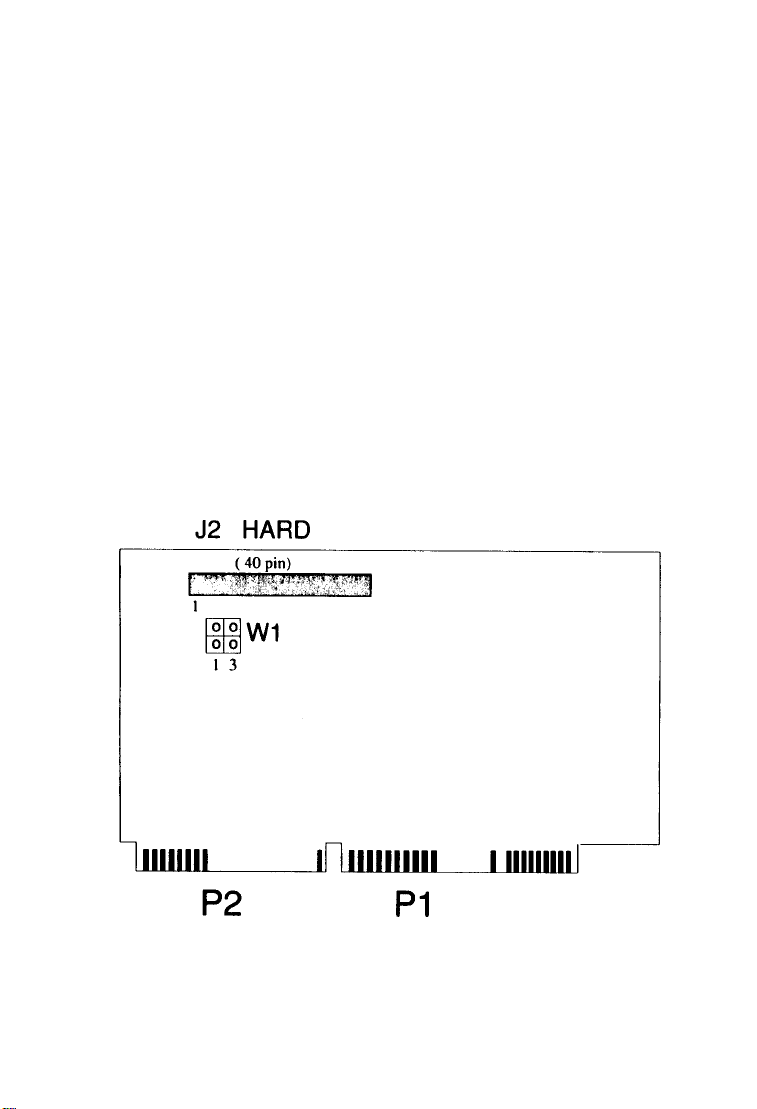
Figure 1-1. WDAT- 140 Adapter Board
Page 3
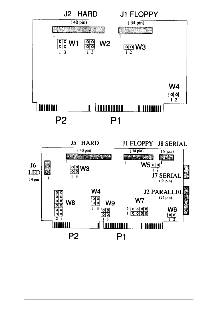
Figure 1-2. WDAT-240 Adapter Board
Figure 1-3. WDAT Adapter Board
Western Digital Corporation 1-3
Page 4

Jumpers
Installing a jumper shunt or rem oving a jumper shunt from the
pins on a jumper block turns certain functions on or off. These functions
define the peripheral hardware to your computer.
Western Digital configures the jumpers for the most common applicat ions. I t i s unli kely t hat you will need to change any of the jumper
settings.
Jumper Settings for the WDAT-140
The WDAT-140 board contains one jumper block, W1, which
allows the DIRQl4 signal to pass directly to the host.
Do I Need to Change Any Jumpers?
No. Do
board, unless you have an or igina l Conner CP342 or CP3022 inte lligent
drive in an IBM AT. The factory default jumper setting is shown below.
Jumper settings are discussed in detail in Appendix B, Table B-1.
If you need to change the jumper settings, do this before you
install the WDAT- 140 board into your computer. You change the
jumper set tings by ins talli ng or removing t he jumper shunt s on the W1
jumper block. Go to Appendix B for exact instructions
change the jumper settings. If you do not need to change t he jumpers,
you can proceed to Chapter 2.
NOT
change any jumper settings on your WDAT- 140
BEFORE
you
Jumper Settings for the WDAT-240
The WDAT-240 board contains four jumper blocks (W1, W2, W3,
and W4) which define hardware parameters. By moving the jumper
shunts, you can cha nge the def inition of the hardware which is attached
to your computer. The jumpers must be configured to match your system
hardware.
1-4 Western Digital Corporation
Page 5

Do I need to Change Any Jumpers?
Probably not. We recommend that you not change any of the
jumper settings unless you have one of the following conditions:
• You have an original Conner CP342 or CP3022 intelligent
drive in an IBM AT.
• You want to disable the floppy drive controller or set an
alternate address at 370-377.
• You have a two-speed floppy drive.
• You want to connect logic ground to the chassis.
The factory de fault jum per se tti ngs ar e shown be low. WI jum per
block allows the DIRQ14 signal to pass directly to the host. Jumper
blocks W2 and W3 define the floppy address and floppy drive speed. W4
defines the ground connection. Jumper settings are discussed in detail in
Appendix B, Tables B-2 through B-5.
DIRQ14 passed directly to host bus 13
Floppy controller enabled
Floppy primary address is 3F0-3F7
Single speed floppy drive
(Dual speed floppy drive is selected, if this jumper block is
installed and jumpered.)
Logic ground is not connected to chassis
(Logic ground is connected to chassis, if this jumper block
is installed and jumpered.)
If you need to change the jumper settings, do this before you
install the WDAT-240 board into your computer. You change the jumper
settings by installing or removing the jumper shunts on the jumper
blocks (WI through W4). Go to Appendix B for exact instructions
BEFORE you change the j umper s ett ings. I f you do not ne ed to change
the jumpers, you can proceed to Chapter 2.
Western Digital Corporation 1-5
Page 6

Jumper Settings for the WDAT-440
The WDAT-440 board contains seven jumper blocks, W3 through
W9, which define ha rdware paramet ers. By moving the j umper shunts,
you can change the def ini ti on of the ha rdware which i s att ached t o your
computer. The jumpers must be configured to match your system
hardware.
Do I Need to Change Any Jumpers?
Probably not. We recommend that you not change any of the
jumper settings unless you have one of the following conditions:
• You have an original Conner CP342 or CP3O22 intelligent
drive in an IBM AT.
• You want to set an alternate address at 370-377.
• You have a two-speed floppy drive.
• You want to change printer port or seri al port definitions or
addresses . You can change the j umper sett ings t o re- confi gure
the parallel port as LPT2. You can also re-configure the
external serial port as COM3 and the internal serial port as
COM4 by moving the jumpers.
• You want to connect logic ground to the chassis.
The factory default jumper settings are shown below. Jumper
blocks W3 and W9 define the hard disk drive interf ace and W4 and W5
define the floppy address and floppy drive speed. The jumpers at W7 and
W8 define the parallel and serial ports. W6 defines the chassis-to-ground
logic (chassis ground is independent of logic ground). Jumper settings
are discussed in detail in Appendix B, Tables B-6 through B-12.
If you need to change the jumper settings, do this before you
instal l the WDAT440 board into your comput er. You change the j umper
settings by installing or removing the jumper shunts on the jumper
blocks (W3 through W9). Go to Appendix B for exact instructions
BEFORE
the jumpers, you can proceed to Chapter 2.
you change the j umper s ett ings. I f you do not ne ed to change
1-6 Western Digital Corporation
Page 7

W3 DIRQI4 passed directly to host bus
W4 Floppy controller enabled
Floppy primary address is 3F0-3F7
W5 Single speed floppy drive
W6 Logic ground not connected to chassis
W7 COM 1 Interrupt = IRQ4
COM2 Interrupt = IRQ3
Parallel printer interrupt = IRQ7
W8 Internal serial port = COM2 (2F8-2FF)
External serial port = COM1 (3F8-3FF)
Printer address, LPTl = 378-37F
Printer enabled
W9 Hard disk drive enabled
Western Digital Corporation 1-7
 Loading...