

Page 1

Table 6 below lists the default jumper settings for the WDl007V-SE2 which supports two 5.25 or
3.5-inch drives. The WDl007V-SEl is a hard disk only version of the controller.
TABLE 6. DEFAULT JUMPER SETTINGS
JUMPER FUNCTION
W1 1-2 No Jumper Cacheing Enabled
3-4 No Jumper 4 Bytes ECC
5-6 No Jumper Translation Enabled
7-8 No Jumper Reserved
9-10 No Jumper SPT Determined by Drive Jumpers
11-12 No Jumper No Alternate Sector
W3 1-2 No Jumper BIOS ROM Enabled
W5 1-2 No Jumper Single Speed Floppy Drive
W6 1-2 No Jumper Primary Floppy Address (3F2-3F7)
W7 1-2-3 Jumper 1-2 lRQl4 Enabled
W8 1-2-3 Jumper 2-3 BIOS Address is CC00:0000 to CC00:3FFF
W12 1-2 No Jumper Primary Hard Disk Address (1 F0-1 F7)
W1 Jumper Connection. Jumper connections W1
1-2, 3-4, 5-6, 9-10, and 11-12 select the 80C188
firmware options as shown in Table 6 when no
jumpers are installed. When jumpered, the
following options are selected. Note: If you are
merely replacing a WDl007A controller with a
WDl007V controller, and you do not wish to
reformat your currently installed drive(s), you
must emulate the l007A mode by installing
jumpers on W1 9-10 and W1 11-12.
W1 1-2: When this jumper is installed, no cacheing occurs.
When no jumper is installed, cacheing is enabled.
Cacheing increases overall system performance by
reading ahead and buffering data sectors likely to
be requested by the host on subsequent read
commands.
W1 3-4: When this jumper is installed, Read
Long and Write Long operations use the seven
byte ECC mode.
When no jumper is installed, four byte ECC mode
is selected. When using four byte ECC mode,
three ECC bytes are temporarily saved until the
next command or data transfer occurs.
W1 5-6: When this jumper is installed, no disk
address translation occurs. The controller assumes
that the logical values indicated by the Set
Parameters command are the true physical values
of the drive.
If no jumper is installed, logical-to-physical
translation occurs. The generic translation
algorithm converts any logical format to the
physical format of the drive. However, the
maximum logical parameters for the system BIOS
INT 13 are 63 SPT 16 heads and 1024 cylinders.
W1 7-8: This jumper connection is reserved. No
jumper should be installed
W1 9-10: Installing this jumper and issuing a Set
Parameters command to the drive will set the
drive to 35 SPT This overrides the drive sector
size switches. This jumper has no effect on drives
having data transfer rates of 15 Mbits per second.
Without a jumper, the controller uses the physical
SPT value presented by the drive (as determined
by the drive's jumper settings).
Page 2
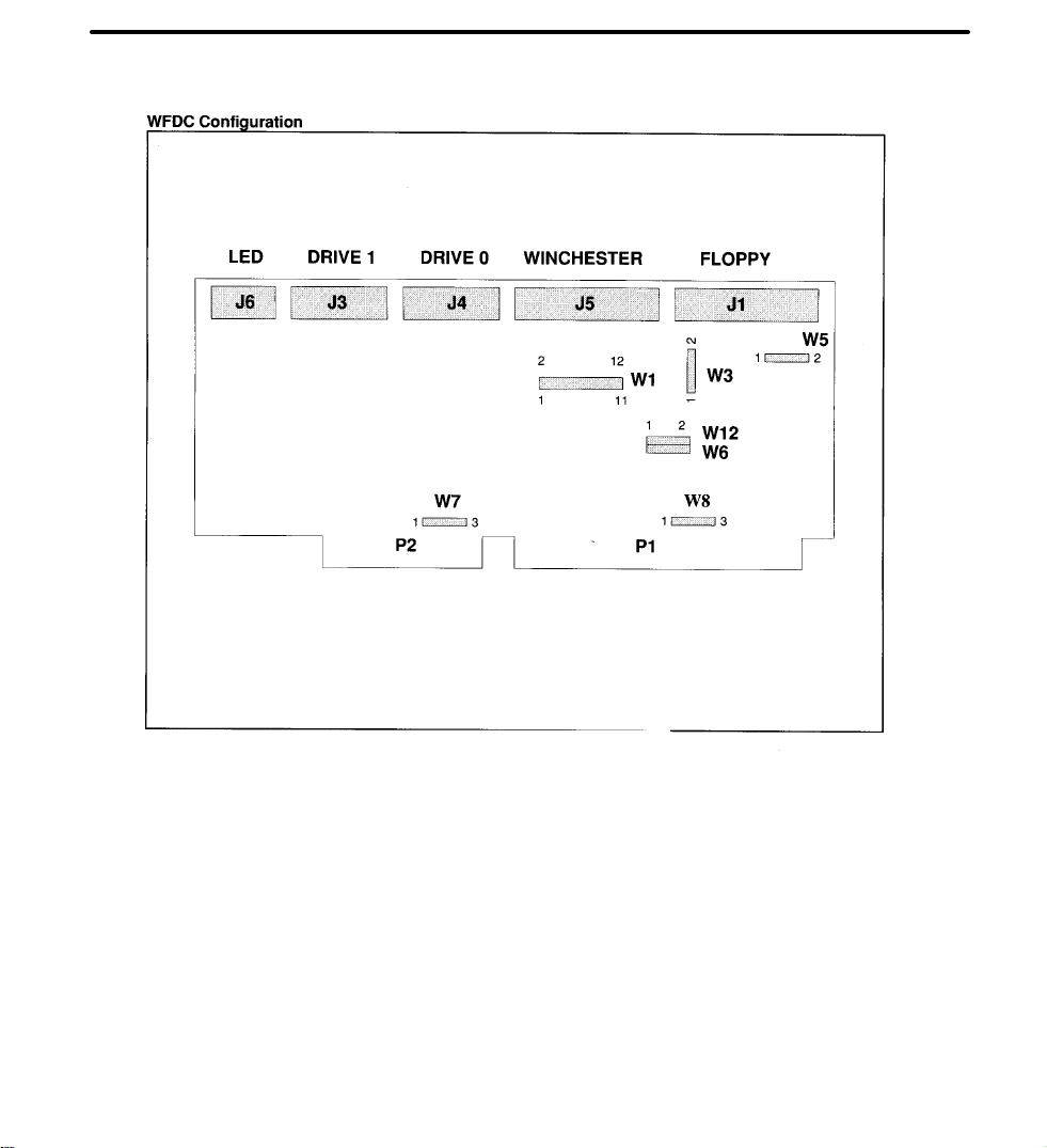
WFDC Configuration
Note: The WD1007V-SE1 version of this controller does not
support floppy drives and jumpers W5 and W6 are not used.
FIGURE 2. CONTROLLER MODULE LAYOUT
Figure 2 illustrates the general module jumper
placement and approximate connector locations.
The module dimensions are 13.12 by 4.2 inches
and a mounting bracket is included. Jumper con-
figurations for the WFDC module appear in Table
.
6
Page 3

W1 11-12:
nate sector per track is provided. The alternate
sector is useful when deallocating media defects.
Mapping out media defects is important if the
operating system can accommodate only a certain
number of errors.
W3 Jumper Connection.
BIOS option, place a jumper on W3 1-2.
W5 Jumper Connection.
supports single speed floppy drives. When
jumpered, dual-speed floppy drives are supported.
W6 Jumper Connection.
secondary address range of 372-377 for floppy
drives, install a jumper on W6 1-2. The primary
address ranges of 3F2-3F7 is selected when
jumpers are not installed.
W7 Jumper Connection.
offers the default interrupt request, IRQ1 4, which
is selected by the factory installed jumper, W7 1-
2. IRQ 15 may be selected by moving the
When a jumper is installed, an alter-
To disable the installed
The WD1007V-SE2
To select the module's
The 1 007V-SE1 /SE2
jumper on W7 1-2 to W7 2-3. Note that MSDOS, OS/2 and most other operating systems
work only with IRQ14. Some operating systems
may work with IRQ15 if custom drivers are
installed.
W8 Jumper Connection.
select the BIOS address range CC000 through
CFFFF or, if expressed as a "segment:offset" address, 0000:0000 to C000:3FFF (CF00:0FFF).
The overlay RAM occupies 256 bytes of the BIOS
address range and is enabled following any
memory write access to the address range. By
removing the jumper from W8 2-3 and placing it
on jumper W8 1-2, the BIOS address range can be
changed to C8000 through CBFFF or, if expressed
as a segment:offset address, C800:0000 to
C800:3FFF (CB00:0FFF).
W12 Jumper Connection.
secondary address range for fixed drives (170-
177), place a jumper on W12 1-2. The primary
address range, 1 F0-1 F7. is selected when
jumpers are not installed.
W8 2-3 is jumpered to
To select the module's
 Loading...