

Page 1

USER'S GUIDE
WD1006V-SR1
Winchester Disk
Controller
WD 1006V-SR2
Winchester/Floppy
Disk Controller
Important Information
Do Not Discard
Page 2
Product Description
This document describes the hardware and software installation of the
WDl006V-SRl and WDl006V-SR2, 16-bit disk controllers for the
IBM* Personal Computer AT* or AT compatible computer. Both
controllers' Winchester interface conform to 2,7 RLL specifications.
The WD1006V-SR2's floppy controller supports four floppy drive
types (360 KB, 720 KB, 1.2 MB and 1.44 MB). Do not confuse the
number of drive types with the number of drives that can be connected
to the WD1006V-SR2. Only two internal drives can be connected to
the WD1006V-SR2. The WDl006V-SR2 supports "intelligent" 1.44
MB media drives. These intelligent drives obtain the drive type and
data rate from the drive's media and do not depend upon the state of J1
pin 2 for this information.
Installation
This section briefly describes the installation of the controller board. Do
NOT use the WD1006V-SR2 with an AT configured, AT compatible,
or XT* diskette controller in the same system. Removal of the extra
diskette controller is necessary for proper operation of the WD1006VSR2. Disabling the diskette controller on the WD1006V-SR2 is NOT
possible.
A minor incompatibility exists between the WD10006V-SRl (or
Wl006V-SR2) and the WD1003-WAH (WD1003-WA2). If the drive
contains more than eight heads, e.g. a 16 head drive, the WD1003WAH numbers heads 8 through 15 as 0 through 7 in the media's ID
fields. The WD1006V controllers number heads 8 through 15 as 8
through 1.5. Backup and reformat the drive to solve this problem. This
problem is not manifested in drives with less than eight heads.
CAUTION
Handle the controller board by the ends of the board. Some of the
chips are static sensitive and damage may occur if the board is
incorrectly handled.
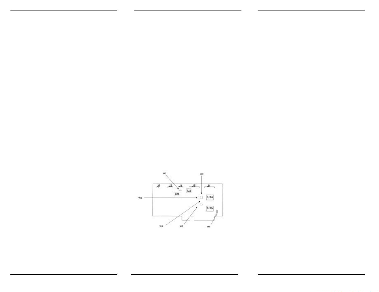
1. Verify the controller jumper settings. Only verify the settings.
Modification of the standard factory settings is rarely necessary. Modify
jumpers only under the direction of a qualified individual; i.e. your
dealer. Figure 1 illustrates the jumper locations for both controller
boards. Refer to Table 1 for further information on jumper settings.
2. Verify termination on last drive. Verify proper setting of drive select
switches. Consult the drive technical manual for proper drive
termination and selection information.
*IBM and AT are registered trademarks and XT is a trademark of
International Business Machines Corporation.
3. Remove the blank expansion slot bracket. Put the bracket
away and save it for possible future use. The screw will be
used to hold the new controller board in place. It is best to
locate the controller in the closest available expansion slot
relative to the drive.
4. Attach the drive control cable connector to J5.
5. Attach the control cable to drive(s).
6. Attach drive 0 data cable connector to J4.
7. Attach data cable to drive 0.
8. Attach drive 1 data cable connector to J3.
9. Attach data cable to drive 1.
10. For WDl006V-SR2 users, attach the diskette cable
connector to J1.
11. For WD1006V-SR2 users, attach cable to floppy drive(s).
12. Attach the Winchester activity cable connector to J6.
13. Check the cable connections carefully . Ensure that pin 1
on the board connectors mates with pin 1 on the cable
connectors. Pin 1 on the cable connectors is usually on the
color coded side.
14. Install the controller board into the expansion slot. Make
sure that the board is seated properly by pressing down on
both ends of the board. Secure the board with the bracket
screw.
15. Remove or disable any other floppy controller in your
system. The WD floppy controller can not be disabled.
All jumpers OFF for factory defaults.
TABLE 1. JUMPER SETTINGS
Jumper/
Pin number Position Description
W1/
1-2 OFF Winchester(s) in
latched mode.
ON Winchester(s) in
non-latched mode.
3-4 OFF Four byte ECC.
Factory default.
ON Seven byte ECC
5-6 OFF Cacheing enabled.
ON Cacheing disabled.
W2
1-2 OFF BIOS enabled.
ON BIOS disabled.
W3/
1-2 OFF Primary Winchester
I/O addresses
ON Secondary Winches-
ter I/O addresses
W4/
1-2 OFF Primary floppy I/O
addresses
ON Secondary floppy I/O
addresses
W5/
1-2 OFF Single speed drives.*
ON Dual speed drives.*
W6/
1-2 OFF Bracket ground op-
eration not used.
ON Connects bracket to
*
Do not combine single and dual speed drives in the same system.
board ground
Figure 1. Jumper Locations
1 2 3
Page 3

Software Installation
This section contains instructions for low level formatting the
Winchester drives. You can low level format the Winchester drive(s)
by one of two methods. Third party software available from Storage
Dimensions*, Ontrack*, or other companies can low level format the
drive(s). Consult your dealer for further information on these software
packages. An on-board BIOS ROM can also low level format the
drive(s). The DEBUG utility initiates the controller's format program.
To low level format the drive(s) with the BIOS ROM, proceed as
follows:
1. Turn on the power.
2. At the A>promt, load and run the DEBUG utility by typing
DEBUG followed by a RETURN. "CR" stands for carriage return or
ENTER.
A>DEBUG CR
3. At the debug prompt, initiate the controller format program by typing
the following command line:
-g=ccOO :5
CAUTION
Step 4 requires execution of low level format. The low level format
destroys all data on the drive. If the drive contains useful data,
backup the drive before executing the low level format program.
4. The controller format program displays a menu. Follow the menu
selections one through six. The change current drive parameters
selection allows you to either choose preprogrammed drive parameters
or enter the parameters from the keyboard. Low level formatting the
drive sets up track, sector, and error correction information and
initializes the data fields. The surface analysis performs a thorough
scan of the drive's media. Running the surface analysis may take
several hours. The verify drive option is a shorter version of the surface
analysis test. Both the surface analysis and verify drive tests report any
defects found and prompts the user to map out these defects. The enter
defect list option allows the user to enter defects provided by the drive
manufacturer. The select next drive allows you to change drives.
5. Load and execute the FDISK and FORMAT utilities.
*
Storage Dimensions is a trademark of Storage Dimensions. Ontrack is
a trademark of Ontrack Computer Systems.
4 5
 Loading...