

Page 1

Working Draft Project
American National T13/2132-D
Standard
Revision 3
June 23, 2010
Information technology Enhanced Disk Drive - 4 (EDD-4)
This is a draft proposed American National Standard of Accredited Standards Committee INCITS. As such this is
not a completed standard. The T13h Technical Committee may modify this document as a result of comments
received during public review and its approval as a standard. Use of the information contained here in is at your
own risk.
Permission is granted to members of INCITS, its technical committees, and their associated task groups to
reproduce this document for the purposes of INCITS standardization activities without further permission,
provided this notice is included. All other rights are reserved. Any commercial or for-profit replication or
republication is prohibited.
T13h Technical Editor: Curtis E. Stevens
Western Digital Technologies, Inc.
20511 Lake Forest Dr.
Lake Forest, Ca. 92630
USA
Telephone:949-672-7933
Email: Curtis.Stevens@wdc.com
Reference number
ISO/IEC xxxx-xxx:200x
ANSI INCITS xxx-200x
Page 2

T13/2132-D Revision 3 June 23, 2010
Points of Contact
T13h Chair T13h Vice-Chair
Dan Colgrove Jim Hatfield
Hitachi Global Storage Technologies Seagate Technology
2903 Carmelo Dr 389 Disc Drive
Henderson, NV 89502 Longmont CO 80503
Tel: 702-614-6119 Tel: 720-684-2120
Fax: 702-614-7955 Fax: 720-684-2766
INCITS Secretariat
INCITS Secretariat Tel: 202-737-8888
1250 Eye Street, NW Suite 200 Fax: 202-638-4922
Washington, DC 20005
Email: INCITS@ITIC.ORG
T13h Reflector
See the T13h Web Site at http://www.t13h.org for reflector information.
T13h Web Site
http://www.t13h.org
T13h FTP Site
ftp.t13h.org (see www.t13h.org for login information)
Document Distribution
INCITS Online Store http://www.techstreet.com/incits.html
managed by Techstreet Telephone: 1-734-30?..?801
1327 Jones Drive or 1-800-699-9277
Ann Arbor, MI 48105 Facsimile: 1-734-302-7811
or
Global Engineering http://global.ihs.com/H
15 Inverness Way East Telephone: 1-303-792-2181
Englewood, CO 80112-5704 or 1-800-854-7179
Facsimile: 1-303-792-2192
American National Standard
for Information Technology
ii Working Draft Enhanced Disk Drive - 4 (EDD-4)
Page 3

June 23, 2010 T13/2132-D Revision 3
Draft
Draft
Secretariat
Information Technology Industry Council
Approved mm.dd.yy
American National Standards Institute, Inc.
This standard describes services currently in use on IA-32 and IA-64 compatible architecture personal computer
systems. These services are provided by BIOS firmware to support hard disks up to 16 exabytes (16x10
bytes). This standard also provides BIOS level services for determining the relationship between BIOS device
numbers and the physical mass storage devices attached to the personal computer. The services defined in this
standard can be applied to mass storage devices with ATA, ATAPI, SCSI, USB, Fibre Channel, 1394, I
other interfaces. In addition, this standard defines the following:
a) formatting required to make a CD or DVD bootable;
b) INT 13h services used to access devices <8GB; and
c) addressing information for Infiniband, Serial ATA, Hypertransport, and PCI Express
.
Working Draft Enhanced Disk Drive - 4 (EDD-4) iii
ABSTRACT
18
O, and
2
Page 4

T13/2132-D Revision 3 June 23, 2010
American
National
Standard
Approval of an American National Standard requires verification by ANSI that the
requirements for due process, consensus, and other criteria for approval have been met by
the standards developer. Consensus is established when, in the judgment of the ANSI
Board of Standards Review, substantial agreement has been reached by directly and
materially affected interests. Substantial agreement means much more than a simple
majority, but not necessarily unanimity. Consensus requires that all views and objections be
considered, and that effort be made towards their resolution.
The use of American National Standards is completely voluntary; their existence does not in
any respect preclude anyone, whether he has approved the standards or not, from
manufacturing, marketing, purchasing, or using products, processes, or procedures not
conforming to the standards.
The American National Standards Institute does not develop standards and will in no
circumstances give interpretation on any American National Standard. Moreover, no person
shall have the right or authority to issue an interpretation of an American National Standard
in the name of the American National Standards Institute. Requests for interpretations
should be addressed to the secretariat or sponsor whose name appears on the title page of
this standard.
CAUTION NOTICE: This American National Standard may be revised or withdrawn at any
time. The procedures of the American National Standards Institute require that action be
taken periodically to reaffirm, revise, or withdraw this standard. Purchasers of American
National Standards may receive current information on all standards by calling or writing the
American National Standards Institute.
The patent statement goes here.
If no patents have been disclosed place the statement in 5.5.2 shall be used.
If any patents have been disclosed place the statement in 5.5.3 shall be used.
Published by
American National Standards Institute
11 W. 42nd Street, New York, New York 10036
Copyright © 2007 by Information Technology Industry Council (ITI).
All rights reserved.
No part of this publication may by reproduced in any
form, in an electronic retrieval system or otherwise,
without prior written permission of ITI, 1250 Eye Street NW, Suite 200,
Washington, DC 20005.
Printed in the United States of America
iv Working Draft Enhanced Disk Drive - 4 (EDD-4)
Page 5
June 23, 2010 T13/2132-D Revision 3
Document Status
The text which is highlighted in green may affect backward compatibility.
Revision History
Rev Date Description
0 January 21, 2009 1) Used ACS-2r1 as the template for this first draft.
2) Populated this template with d1572r3.doc (EDD-3)
3) Used ACSC-2 definitions for byte, word, DWord, and QWord since
ACS-2 has a complete set of conventions.
4) Incorporated Erratum
5) Added editors notes where there were issues were found during
conversion.
1 July 29, 2009 1) Integrated e08134r1. This changes the definition of the device path.
Added definitions of both SATA and PATA to definition of terms. Definitions were taken from ACS-2 verbatim.
2) Integrated e09103r1. This obsoletes Read Long, Write Long, Seek,
Extended Seek, and Recalibrate.
3) Integrated e09102r3. This adds a Trusted Computing BIOS function
2 June 22, 2010 1) Incorporated e09136r0 - EDD-4r1 Updates from 30-Jul telecon and
19-Aug plenary.
2) Performed a spell check
3) Normalized periods to followed by 2 spaces.
4) Incorporate e09127r3
3 June 23, 2010 1) Corrected links that were not hot
2) Removed cut and paste artifacts from 2 notes in Annex A
New Capabilities added to EDD-4
Integrated Proposal List
# Doc Description
1 e08134r1 Updates SATA path definition
2 e09103r1 Obsoletes Read Long, Write Long, Seek, Extended Seek, and Recalibrate
3 e09102r3 Adds a Trusted Computing INT 13h BIOS function
4 e09127r3 Adds an Annex describing peaceful coexistence of MBR and GPT
Working Draft Enhanced Disk Drive - 4 (EDD-4) v
Page 6

T13/2132-D Revision 3 June 23, 2010
Contents
Page
Points of Contact....................................................................................................................................................ii
Document Status ...................................................................................................................................................v
New Capabilities added to EDD-4 .........................................................................................................................v
Contents................................................................................................................................................................ vi
Tables ...................................................................................................................................................................ix
Figures ...................................................................................................................................................................x
Foreword............................................................................................................................................................... xi
Introduction ...........................................................................................................................................................xi
1 Scope ................................................................................................................................................................. 1
2 Normative references ......................................................................................................................................... 3
2.1 General ..................................................................................................................................................... 3
2.2 Approved references ................................................................................................................................ 3
2.3 References under development ............................................................................................................... 4
2.4 Other references ....................................................................................................................................... 4
3 Definitions, abbreviations, and conventions ....................................................................................................... 5
3.1 Definitions and abbreviations ................................................................................................................... 5
3.2 Symbols and abbreviations ...................................................................................................................... 6
3.3 Conventions .............................................................................................................................................. 6
3.3.1 Overview ......................................................................................................................................... 6
3.3.2 Precedence ..................................................................................................................................... 7
3.3.3 Lists ................................................................................................................................................. 7
3.3.4 Keywords ........................................................................................................................................ 8
3.3.5 Numbering ....................................................................................................................................... 8
3.3.6 Bit conventions ................................................................................................................................ 9
3.3.7 Number range convention ............................................................................................................... 9
3.3.8 Register and CF Contents ............................................................................................................... 9
3.3.9 Interrupt Services and Functions .................................................................................................... 9
3.3.10 Byte, word, DWord, and QWord Relationships ........................................................................... 10
3.3.11 ATA string convention ................................................................................................................. 10
4 Overview .......................................................................................................................................................... 12
5 <8GB INT 13h Functions (Conventional Functions) ........................................................................................ 13
6 >8GB INT 13h Functions ................................................................................................................................. 15
6.1 Overview ................................................................................................................................................. 15
6.2 Data Structure ........................................................................................................................................ 15
6.3 Removable Media ................................................................................................................................... 17
6.4 ...................................................................................................................... INT 13h Interface Subsets 17
6.4.1 Overview ....................................................................................................................................... 17
6.4.2 Fixed Disk Access Subset ............................................................................................................. 17
6.4.3 Device Locking and Ejecting Subset ............................................................................................. 18
6.4.4 Enhanced Disk Drive (EDD) Support Subset ................................................................................ 18
vi Working Draft Enhanced Disk Drive - 4 (EDD-4)
Page 7

June 23, 2010 T13/2132-D Revision 3
7 CD/DVD Boot ................................................................................................................................................... 19
7.1 Overview ................................................................................................................................................. 19
7.2 Boot Methods ......................................................................................................................................... 21
7.2.1 Overview ....................................................................................................................................... 21
7.2.2 Emulation Process ........................................................................................................................ 21
7.2.3 No Emulation Boot ........................................................................................................................ 22
7.2.4 Floppy Boot ................................................................................................................................... 22
7.2.5 Hard Drive Boot ............................................................................................................................. 22
7.3 CD/DVD Format ..................................................................................................................................... 23
7.3.1 Overview ....................................................................................................................................... 23
7.3.2 Boot Volume Descriptor (BVD) ..................................................................................................... 23
7.3.3 Validation Entry ............................................................................................................................. 24
7.3.4 Initial/Default Entry ........................................................................................................................ 25
7.3.5 Section Header ............................................................................................................................. 25
7.3.6 Section Entry ................................................................................................................................. 27
7.3.7 Section Entry Extension ................................................................................................................ 28
8 INT 13h Function Definitions ............................................................................................................................ 29
8.1 Overview ................................................................................................................................................. 29
8.2 Reset Disk Subsystem (FN 00h) ............................................................................................................ 30
8.3 Get Status of Last Operation (FN 01h) ................................................................................................... 31
8.4 Read Sectors into Memory (FN 02h) ...................................................................................................... 32
8.5 Write Sectors From Memory (FN 03h) ................................................................................................... 33
8.6 Verify Sectors (FN 04h) .......................................................................................................................... 34
8.7 Get Drive Parameters (FN 08h) .............................................................................................................. 35
8.8 Read Buffer (FN 0Eh) ............................................................................................................................. 36
8.9 Write Buffer (FN 0Fh) ............................................................................................................................. 37
8.10 Get Disk Type (FN 15h) ........................................................................................................................ 38
8.11 Set Media Type (FN 18h) ..................................................................................................................... 39
8.12 Park Heads (FN 19h) ............................................................................................................................ 40
8.13 Identify Device Information (FN 25h) .................................................................................................... 41
8.14 Check Extensions Present (FN 41h) .................................................................................................... 42
8.15 Extended Read (FN 42h) ...................................................................................................................... 43
8.16 Extended Write (FN 43h) ...................................................................................................................... 44
8.17 Verify Sectors (FN 44h) ........................................................................................................................ 45
8.18 Lock/Unlock Media (FN 45h) ................................................................................................................ 46
8.19 Eject Removable Media (FN 46h) ........................................................................................................ 47
8.20 Get Device Parameters (FN 48h) ......................................................................................................... 48
8.20.1 Overview ..................................................................................................................................... 48
8.20.2 Interface Path .............................................................................................................................. 50
8.20.3 Device Path ................................................................................................................................. 51
8.20.4 Device Parameter Table Extension (DPTE) ................................................................................ 54
8.21 Get Extended Media Change Status (FN 49h) ..................................................................................... 58
8.22 Initiate Disk Emulation (FN 4Ah) .......................................................................................................... 59
8.23 Terminate Disk Emulation (FN 4Bh) ........................................................................................
8.24 Initiate Disk Emulation & Boot (FN 4Ch) .............................................................................................. 63
8.25 Return Boot Catalog (FN 4Dh) ............................................................................................................. 64
8.26 Set Hardware Configuration (FN 4Eh) .................................................................................................. 65
8.27 Send Packet Command (FN 50h) ........................................................................................................ 66
8.27.1 Overview ..................................................................................................................................... 66
8.27.2 Packet Sending Service (PSS) For SCSI Command Descriptor Blocks (CDB) .......................... 66
8.28 Security Protocol Commands (FN 51h) ................................................................................................ 69
............. 62
9 INT 15h Removable Media Eject ..................................................................................................................... 70
Annex A (informative) Hybrid MBR boot .............................................................................................................. 71
A.1 Hybrid MBR boot overview ..................................................................................................................... 71
Working Draft Enhanced Disk Drive - 4 (EDD-4) vii
Page 8

T13/2132-D Revision 3 June 23, 2010
A.2 GPT support for hybrid MBR boot code ................................................................................................. 71
A.3 Hybrid MBR boot code ........................................................................................................................... 72
A.4 Hybrid MBR boot code endeavor procedure .......................................................................................... 73
A.5 Hybrid VBR boot code ............................................................................................................................ 74
viii Working Draft Enhanced Disk Drive - 4 (EDD-4)
Page 9

June 23, 2010 T13/2132-D Revision 3
Table s
Page
Table 1 - Approved ANSI References.................................................................................................................... 3
Table 2 - References Under Development ............................................................................................................ 4
Table 3 - Numbering conventions .......................................................................................................................... 9
Table 4 - ATA string byte swapping ..................................................................................................................... 11
Table 5 - ATA firmware revision example ............................................................................................................ 11
Table 6 - Conventional Register Definitions......................................................................................................... 13
Table 7 - Conventional Function Definitions ........................................................................................................ 14
Table 8 - Extended Function Definitions .............................................................................................................. 15
Table 9 - Device Address Packet......................................................................................................................... 16
Table 10 - Removable Media Return Codes........................................................................................................ 17
Table 11 - Fixed Disk Access .............................................................................................................................. 17
Table 12 - Locking and Ejecting........................................................................................................................... 18
Table 13 - EDD Support....................................................................................................................................... 18
Table 14 - Floppy Geometries ............................................................................................................................. 22
Table 15 - Boot Volume Descriptor...................................................................................................................... 23
Table 16 - Validation Entry................................................................................................................................... 24
Table 17 - Initial/Default Entry.............................................................................................................................. 25
Table 18 - Section Header ................................................................................................................................... 26
Table 19 - Section Entry ...................................................................................................................................... 27
Table 20 - Section Entry Extension...................................................................................................................... 28
Table 21 - Interface Support Bit Map ................................................................................................................... 42
Table 22 - Result Buffer ....................................................................................................................................... 48
Table 23 - Interface Path Definitions.................................................................................................................... 50
Table 24 - Device Path Definitions....................................................................................................................... 52
Table 25 - Device parameter table extension ...................................................................................................... 54
Table 26 - Translation Type ................................................................................................................................. 57
Table 27 - CD Specification Packet ..................................................................................................................... 60
Table 28 - CD Command Packet ......................................................................................................................... 64
Table 29 - Hardware Configuration Sub-Functions.............................................................................................. 65
Table 30 - Formatted Command Packet .............................................................................................................. 66
Table 31 - Formatted Protocol Specific Data ....................................................................................................... 67
Table 32 - Output Parameters ............................................................................................................................. 68
Table 33 - Data Buffer for Security Protocol Commands ..................................................................................... 69
Table A.1 - Protective MBR with hybrid MBR boot code...................................................................................... 71
Table A.2 - Hybrid MBR endeavor IA-32 register values ..................................................................................... 73
Table A.3 - Hybrid MBR boot code hand over structure ...................................................................................... 73
Working Draft Enhanced Disk Drive - 4 (EDD-4) ix
Page 10

T13/2132-D Revision 3 June 23, 2010
Figures
Page
Figure 1 - ATA document relationships................................................................................................................ 2
Figure 2 - Byte, word, DWord and QWord relationships .................................................................................... 10
Figure 3 - System Component Diagram ............................................................................................................ 12
Figure 4 - ISO 9660 CD Layout ........................................................................................................................ 19
Figure 5 - Boot CD or DVD with a single boot image........................................................................................ 20
Figure 6 - Boot CD or DVD with multiple boot images ....................................................................................... 21
Figure A.1 - GPT disk layout with hybrid MBR boot code example ................................................................... 71
Figure A.2 - GPT disk layout with hybrid MBR boot code truncation example................................................... 72
x Working Draft Enhanced Disk Drive - 4 (EDD-4)
Page 11

June 23, 2010 T13/2132-D Revision 3
Foreword
Foreword
(This foreword is not part of American National Standard NCITS.xxx-200x)
DOS accesses its mass storage devices using an INT13h programming interface provided by BIOS firmware to
higher-level software. This interface was designed in the early 1980's, upgraded in the late 1980's and upgraded
again in the early 1990's. Initially, INT 13h used a cylinder-head-sector interface that was limited to approx.
528MB of disk addressing. Later this same interface was upgraded to support approx. 8.4GB of disk
addressing. Finally, extended functions were created that allowed 64-bit disk addressing. At this same time,
specifications were created that allowed the CD or DVD ROM drive to boot using the same INT 13h interface that
hard drives used. The Disk and CD/DVD functions have never been fully documented in a standards forum.
This standard enables the following capabilities:
a) CHS addressing with an 8.4GB limitation;
b) Logical Block Addressing (LBA);
c) removes the requirement of using interrupt 41h/46h to point at the Fixed Disk Parameter Table
information;
d) makes location and configuration information available to operating systems that do not use the BIOS to
access mass storage devices;
e) use data structures that apply to both IA-32 and IA-64 compatible architecture systems;
f) use data structures that can address media capacities for the next 20 years; and
g) boot from CD or DVD.
Requests for interpretation, suggestions for improvement and addenda, or defect reports are welcome. They
should be sent to the NCITS Secretariat, Information Technology Industry Council, 1250 I Street NW, Suite 200,
Washington, DC 20005-3922.
This standard was processed and approved for submittal to ANSI by National Committee for Information
Technology Standardization (NCITS). Committee approval of this standard does not necessarily imply that all
committee members voted for approval. At the time it approved this standard, NCITS had the following
members:
Editor’s Note 1: Insert INCITS Membership List Here
Technical Committee T13h on ATA Interfaces, that reviewed this standard, had the following members and
additional participants:
Dan Colegrove, Chair
Jim Hatfield, Vice-Chair
Mark Overby, Secretary
Editor’s Note 2: Insert T13h Membership List Here
Introduction
This standard encompasses the following:
Clause 1 describes the scope.
Clause 2 provides normative references.
Clause 3 provides definitions, abbreviations, and conventions.
Clause 4 is the overview.
Clause 5 is INT 13h functions limited to 8GB if disk addressing.
Clause 6 is INT 13h functions not limited to 8GB of disk addressing.
Working Draft Enhanced Disk Drive - 4 (EDD-4) xi
Page 12

T13/2132-D Revision 3 June 23, 2010
Clause 7 is CD/DVD Booting
Clause 8 is INT 13h function definitions
Clause 9 is INT 15H Removable Media Eject Functions
Annex A describes Hybrid MBR boot
Windows is a registered trademark of Microsoft Corporation in the United States and/or other countries.
xii Working Draft Enhanced Disk Drive - 4 (EDD-4)
Page 13

AMERICAN NATIONAL STANDARD BSR INCITS xxx-200x
American National Standard
for Information Technology –
Enhanced Disk Drive - 4 (EDD-4)
1 Scope
This standard assumes that the reader is familiar with the conventional INT 13h interface, the usage of the BIOS
Device Parameter Table, and the basic operation of mass storage devices. This standard describes in detail
BIOS functions and data structures that are used as an abstraction layer to allow higher-level applications to
access mass storage devices in an interface and command-set independent manner. To comply with this
standard, higher-level software shall call the INT functions using the data structures described herein, and
system firmware shall provide the INT functions and data structures described herein.
The storage industry has increased the capacity and functionality of many types of mass storage devices. This
increase in capacity and functionality has required the development of a BIOS interface. This standard
documents the BIOS interface that is supplied by many BIOS vendors. This standard defines solutions to the
following INT 13h BIOS-specific issues:
a) The INT 13h interface has a limit of 528 megabytes (MB);
b) The INT 13h interface allows more than two devices to be attached to a system but has no consistent
method for storing the additional configuration parameters;
c) The INT 13h interface does not define CHS-independent methods for addressing devices. The methods
defined by the INT 13h interface are not device-geometry independent. A different method of address
representation and operation is needed;
d) Methods of data transfer continue to be added to ATA devices. Capabilities such as, DMA modes,
multi-sector data transfers and PIO modes are not reported to the operating system via the INT 13h
interface;
e) Systems require more than two storage devices, and with this requirement comes the requirement to
assign the order in which the devices are to be accessed. The INT 13h interface does not provide this
capability;
f) The INT 13h interface does not make location and configuration information available to operating
systems that do not use the BIOS to access mass storage devices;
g) The INT 13h interface does not provide a linkage between the BIOS device assignments on the
operating system device letter assignments;
h) The INT 13h interface does not use data structures that apply to both IA-32 and IA-64 compatible
architecture systems.
Working Draft Enhanced Disk Drive - 4 (EDD-4) 1
Page 14
T13/2132-D Revision 3 June 23, 2010
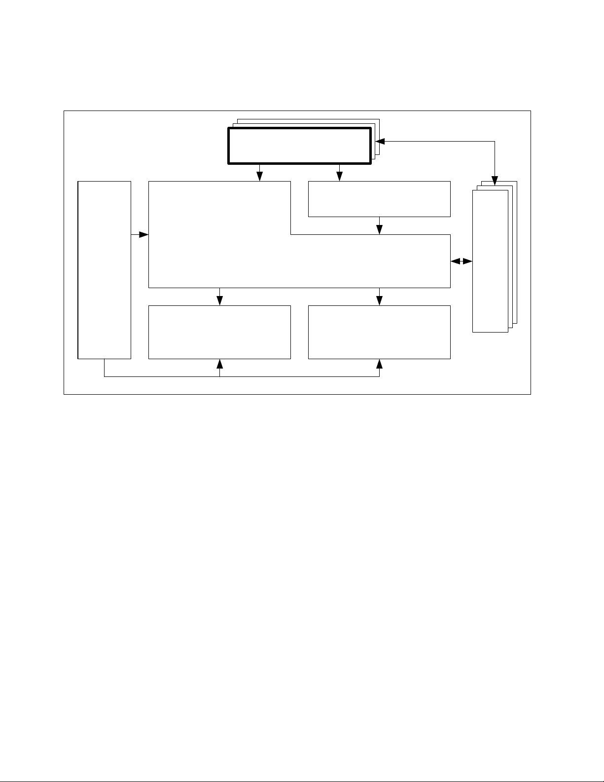
AT Attachment – 8
Architecture Model
(ATA8-AAM)
Packet delivered
command sets
AT Attachment – 8
Parallel Transport
(ATA8-APT)
AT Attachment – 8
Serial Transport
(ATA8-AST)
ATA/ATAPI Command Set - 2 (ACS-2)
EDD-4 and Related host
standards and specifications
Other related
device specifications
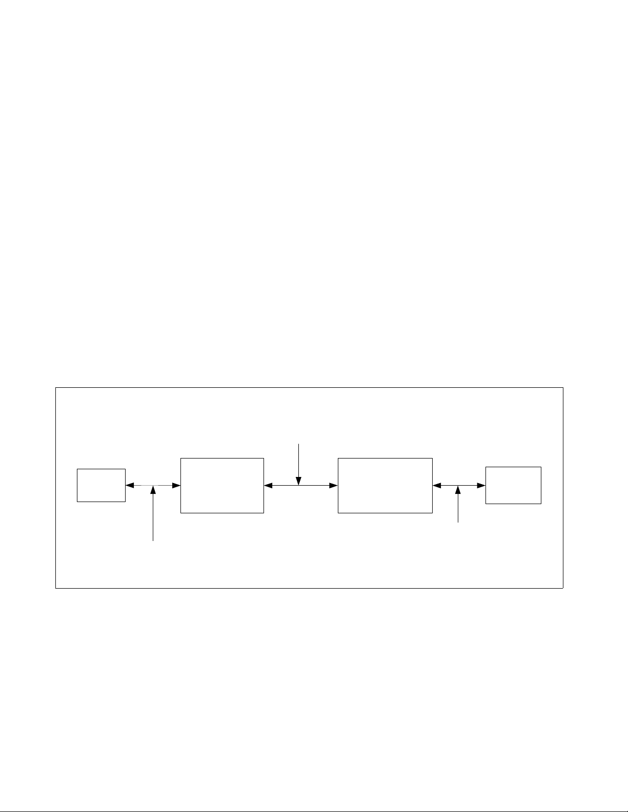
The set of AT Attachment standards consists of this standard and the ATA implementation standards described in
AT Attachment - 8 ATA/ATAPI Architecture Model (ATA8-AAM). Enhance Disk Drive - 4 (EDD-4) specifies a
common set of procedures used to access or boot storage devices. Figure 1 shows the relationship of this
standard to the other standards and related projects in the ATA and SCSI families of standards and
specifications.
Figure 1 — ATA document relationships
2 Working Draft Enhanced Disk Drive - 4 (EDD-4)
Page 15
June 23, 2010 T13/2132-D Revision 3
2 Normative references
2.1 General
The standards list in 2.2, 2.3, and 2.4 contain provisions that, through reference in the text, constitute provisions
of this standard. At the time of publication, the editions indicated were valid. All standards are subject to
revision, and parties to agreements based on this standard are encouraged to investigate the possibility of
applying the most recent editions of the standards listed in 2.2, 2.3, and 2.4.
Copies of these standards may be obtained from ANSI: Approved ANSI standards, approved and draft
international and regional standards (ISO, IEC, CEN/CENELEC, ITUT), and approved and draft foreign
standards (including BSI, JIS, and DIN). For further information, contact ANSI Customer Service Department at
212-642-4900 (phone), 212-302-1286 (fax), or via the World Wide Web at http://www.ansi.org.
Additional availability contact information is provided as needed.
2.2 Approved references
Copies of the following documents may be obtained from ANSI, an ISO member organization:
a) Approved ANSI standards;
b) approved international and regional standards (ISO and IEC); and
c) approved foreign standards (including JIS and DIN).
For further information, contact the ANSI Customer Service Department:
Phone +1 212-642-4900
Fax: +1 212-302-1286
Web: http://www.ansi.org
E-mail: ansionline@ansi.org
or the InterNational Committee for Information Technology Standards (INCITS):
Phone +1 202-626-5738
Web: http://www.incits.org
E-mail: incits@itic.org
Table 1 lists approved ANSI standards, approved international and regional standards (ISO, IEC,
CEN/CENELEC, ITUT). Additional information may be available at http://www.t10.org and http://www.t13h.org.
Table 1 — Approved ANSI References
Name Reference
Volume and File Structure of CD-ROM For Information Interchange ISO 9660-1988
Fibre Channel Framing and Signaling Interface - 2 (FC-FS-2) INCITS 424-2007
(FC-LS) INCITS 433-2006
AT Attachment 8 - ATA/ATAPI Command Set - 8 (ATA8-ACS) INCITS 452-2009
Serial Attached SCSI - 1.1 (SAS-1.1) INCITS 417-2006
Serial Bus Protocol - 2 (SBP-2) INCITS 325-1998
Reduced Block Commands (RBC) INCITS 330-2003
SCSI Primary Commands - 3 (SPC-3) INCITS 408-2005
Multi-Media Commands - 5 (MMC-5) INCITS 430-2007
BIOS Enhanced Disk Drive Services - 3 (EDD-3) INCITS 407-2005
Extended Unique Identifier, 64-bit (EUI-64) ANSI/IEEE 394:1995
IEEE Standard for a High Performance Serial Bus IEEE 1394-2008
Working Draft Enhanced Disk Drive - 4 (EDD-4) 3
Page 16

T13/2132-D Revision 3 June 23, 2010
2.3 References under development
At the time of publication, the referenced standards were still under development. For information on the current
status of the document, or regarding availability, contact the relevant standards body or other organization as
indicated in table 2.
Table 2 — References Under Development
Name Project Number
ATA/ATAPI Command Set - 2 (ACS-2) INCITS 2015D
Serial Bus Protocol - 3 (SBP-3) INCITS 1467D
Multi-Media Commands - 6 (MMC-6) INCITS 1836D
SCSI Primary Commands - 4 (SPC-4) INCITS 1731D
2.4 Other references
These standards and specifications are also referenced.
BIOS Boot Specification (Compaq, Phoenix and Intel),
For the BIOS Boot Specification published by Phoenix Technologies, contact them at www.phoenix.com
El Torito CD-ROM Boot Specification
For the El Torito CD-ROM Boot Specification published by Phoenix Technologies, contact them at
www.phoenix.com
ATAPI Removable Media BIOS Specification
For the ATAPI Removable Media BIOS Specification published by Phoenix Technologies, contact them
at www.phoenix.com
Universal Serial Bus 3.0 Specification
For the Universal Serial Bus 3.0 Specification, contact the USB Implementors Forum at www.usb.org
Mass Storage Overview
For the Mass Storage Overview specification, contact the USB Implementors Forum at www.usb.org,
www.usb.org/developers
Unified Extensible Firmware Interface Specification, Version 2.3 (UEFI-2.3) plus errata
For the UEFI-2.3 specification, contact the Unified EFI Forum at www.uefi.org
4 Working Draft Enhanced Disk Drive - 4 (EDD-4)
Page 17

June 23, 2010 T13/2132-D Revision 3
3 Definitions, abbreviations, and conventions
3.1 Definitions and abbreviations
3.1.1 ATA (AT Attachment) device: An AT Attachment (also known as IDE) is a storage device that
conforms to an ATA standard.
3.1.2 BDA: The BIOS Data Area is an area of reserved memory used by the BIOS and OS to store
data about the system hardware. It is located at memory segment 40h starting with 40h:00h.
3.1.3 BIOS: The Basic Input/Output System (BIOS) is the firmware stored in non-volatile (NV) memory
located on the computer's main board. The BIOS executes POST to test and initialize the
system components and then loads the OS. The BIOS also handles the low-level Input/Output
to the various peripheral devices connected to the computer.
3.1.4 byte: A sequence of eight contiguous bits considered as a unit. See 3.3.10.
3.1.5 Carry Clear: a condition where the Carry Flag in the ELAGS register is cleared to zero.
3.1.6 Carry Set: a condition where the Carry Flag in the EFLAGS register is set to one.
3.1.7 CF: The Carry Flag is a bit in the EFLAGS register in the microprocessor.
3.1.8 CHS: CHS addressing is a method of addressing the contents of a storage device using logical
cylinders (C), logical heads (H), and logical sectors (S). This method of addressing allows a
maximum C=16,383, H=16, S=63, resulting in a maximum device capacity of 8.4 gigabytes
(16,383 16 63 512 bytes per sector 8.4 gigabytes). See LBA addressing for another addressing
method.
3.1.9 Conventional: When a word, term, or phrase is modified by the word "conventional" it refers to
the legacy style, or method of operation that is limited to addressing ATA devices that have a 528
MB capacity or less. See 3.2.10xxx for the definition of "Enhanced".
3.1.10 DOS: DOS is a disk operating system that uses the system BIOS as a firmware abstraction layer
to access system hardware. Examples of DOS based operating systems include MS-DOS
DR-DOS, PC-DOS, Free DOS, Windows
®
3.11, and Windows® 95.
3.1.11 DWord: A sequence of four contiguous bytes considered as a unit. See 3.3.10.
3.1.12 enhanced: When a word, term, or phrase is modified by the word "enhanced" it means there is a
"conventional" and an "enhanced" method of operation. The "enhanced" method is defined by
this standard.
3.1.13 Host: The Host is the computer system that is controlled by the BIOS.
3.1.14 Hybrid MBR boot code: IA-32 compatible code located in the MBR that processes the GPT
disk layout.
3.1.15 Hybrid VBR boot code: IA-32 compatible code located in the VBR that processes the GPT disk
layout.
3.1.16 IA-32 compatible: IA-32 compatible refers to computer processor architectures that are
compatible with the Intel Architecture 32-bit wide processor and data bus.
3.1.17 IA-64 compatible: IA-64 compatible refers to computer processor architectures that are
compatible with the Intel Architecture 64-bit wide processor and data bus.
3.1.18 INT 13h: A BIOS interrupt service that provides a protocol independent method for addressing
floppy, hard drive, and other storage devices.
3.1.19 INT 40h: INT 40h is a BIOS interrupt service that provides a protocol independent method for
addressing INT 13h devices that have a device number less than or equal to 7Fh.
3.1.20 GPT disk layout: The disk layout defined by the Unified EFI specification (see UEFI-2.3).
3.1.21 LBA: LBA is a method of addressing a device that involves using a Logical Block Address. For
example, using 28-bit addressing, this method of addressing allows a maximum sector address
28
-1, or 137.4 GB of data on an ATA device. See CHS for another address method.
of 2
®
,
Working Draft Enhanced Disk Drive - 4 (EDD-4) 5
Page 18

T13/2132-D Revision 3 June 23, 2010
3.1.22 Logical Address/Geometry: A logical address or geometry is used to address a device by an
application, such as DOS, using the INT 13h interface. INT 13h FN 8 returns the logical
geometry of the device.
3.1.23 Master Boot Record (MBR): The first LBA on a disk.
3.1.24 MBR disk layout: The disk layout traditionally used by BIOS based systems.
3.1.25 NV Memory: Non-Volatile memory is memory that retains content even when the power has
been removed. The most common type of NV memory on a computer system is the CMOS
RAM that is used to store system configuration information.
3.1.26 OS: An Operating System is a software abstraction layer that provides services that give
applications access to system hardware, in a hardware independent fashion. Examples of these
services include memory management, multi-threaded task management, file system
management, printer management, and screen management.
3.1.27 PATA (Parallel ATA) device: A device implementing the parallel ATA transport (see ATA8-APT).
3.1.28 POST: The Power-On Self-Test is the part of the BIOS that takes control immediately after power
is applied to the computer. POST initializes the computer hardware so that an OS may be
loaded.
3.1.29 QWord: A sequence of eight contiguous bytes considered as a unit. See 3.3.10.
3.1.30 QWord-aligned pointer: A pointer where the lowest order three bits are 000b.
3.1.31 SATA (Serial ATA) device: A device implementing the serial ATA transport (see ATA8-AST).
3.1.32 seg:offset: An addressing method where the address is calculated by the following formula:
seg*16+offset. This calculation results in a 20 bit linear address space.
3.1.33 Standard Floppy Drive: The Standard Floppy Drive is the generic term to define the currently
used 5.25 inch floppy drives and the 3.5 inch floppy diskette drives found in many systems.
3.1.34 Volume Boot Record (VBR): The first LBA in a bootable partition.
3.1.35 word: A sequence of two contiguous bytes considered as a unit. See 3.3.10.
3.2 Symbols and abbreviations
Abbreviation Meaning
* multiplied by
/ divided by
< less than
> greater than
GPT GUID Partition Table (see UEFI-2.3)
MBR Master Boot Record (see 3.1.24)
OS Operating System (see 3.1.26)
UEFI Unified Extensible Firmware Interface (see UEFI-2.3)
VBR Volume Boot Record (see 3.1.34)
3.3 Conventions
3.3.1 Overview
Lowercase is used for words having the normal English language meaning. Certain words and terms used in this
standard have a specific meaning beyond the normal English language meaning. These words and terms are
defined either in clause 3 or in the text where they first appear.
The names of abbreviations, commands, fields, and acronyms used as signal names are in all uppercase (e.g.,
IDENTIFY DEVICE). Fields containing only one bit are usually referred to as the “name” bit instead of the
“name” field. (See 3.3.6 for the naming convention used for naming bits.)
6 Working Draft Enhanced Disk Drive - 4 (EDD-4)
Page 19

June 23, 2010 T13/2132-D Revision 3
Names of device fields begin with a capital letter (e.g., Count).
The expression “word n” or “bit n” shall be interpreted as indicating the content of word n or bit n.
3.3.2 Precedence
If there is a conflict between text, figures, and tables, the precedence shall be tables, figures, then text.
3.3.3 Lists
3.3.3.1 Lists overview
Lists shall be introduced by a complete grammatical proposition followed by a colon and completed by the items
in the list.
Each item in a list shall be preceded by an identification with the style of the identification being determined by
whether the list is intended to be an ordered list or an unordered list.
If the item in a list is not a complete sentence, then the first word in the item shall not be capitalized. If the item in
a list is a complete sentence, then the first word in the item shall be capitalized,
Each item in a list shall end with a semicolon, except the last item, which shall end in a period. The next to the
last entry in the list shall end with a semicolon followed by an “and” or an “or” (i.e., “...; and”, or “...; or”). The
“and” is used if all the items in the list are required. The “or” is used if only one or more items in the list are
required.
3.3.3.2 Unordered lists
An unordered list is one in which the order of the listed items is unimportant (i.e., it does not matter where in the
list an item occurs as all items have equal importance). Each list item shall start with a lower case letter followed
by a close parenthesis. If it is necessary to subdivide a list item further with an additional unordered list (i.e.,
have a nested unordered list), then the nested unordered list shall be indented and each item in the nested
unordered list shall start with an upper case letter followed by a close parenthesis.
The following is an example of an unordered list with a nested unordered list:
The following are the items for the assembly:
a) a box containing:
A) a bolt;
B) a nut; and
C) a washer;
b) a screwdriver; and
c) a wrench.
3.3.3.3 Ordered lists
An ordered list is one in which the order of the listed items is important (i.e., item n is required before item n+1).
Each listed item starts with an Western-Arabic numeral followed by a close parenthesis. If it is necessary to
subdivide a list item further with an additional unordered list (i.e., have a nested unordered list), then the nested
unordered list shall be indented and each item in the nested unordered list shall start with an upper case letter
followed by a close parenthesis.
The following is an example of an ordered list with a nested unordered list:
The following are the instructions for the assembly:
1) Remove the contents from the box;
2) Assemble the item;
A) Use a screwdriver to tighten the screws; and
B) Use a wrench to tighten the bolts;
and
3) Take a break.
Working Draft Enhanced Disk Drive - 4 (EDD-4) 7
Page 20

T13/2132-D Revision 3 June 23, 2010
3.3.4 Keywords
Several keywords are used to differentiate between different levels of requirements and options.
3.3.4.1 expected: A keyword used to describe the behavior of the hardware or software in the design models
assumed by this standard. Other hardware and software design models may also be implemented.
3.3.4.2 mandatory: A keyword indicating items to be implemented as defined by this standard.
3.3.4.3 may: A keyword that indicates flexibility of choice with no implied preference.
3.3.4.4 N/A: A keyword that indicates a field is not applicable and has no defined value and should not be
checked by the host or device.
3.3.4.5 obsolete: A keyword indicating that the designated bits, bytes, words, fields, and code values that may
have been defined in previous standards are not defined in this standard and shall not be reclaimed for
other uses in future standards. However, some degree of functionality may be required for items desig-
nated as “obsolete” to provide for backward compatibility.
Obsolete commands should not be used by the host. Commands defined as obsolete may be command
aborted by devices conforming to this standard. However, if a device does not return command aborted
for an obsolete command, then the device shall return command completion for the command.
3.3.4.6 optional: A keyword that describes features that are not required by this standard. However, if any
optional feature defined by the standard is implemented, the feature shall be implemented in the way
defined by the standard.
3.3.4.7 prohibited: A keyword indicating that an item shall not be implemented by an implementation.
3.3.4.8 reserved: A keyword indicating reserved bits, bytes, words, fields, and code values that are set aside for
future standardization. Their use and interpretation may be specified by future extensions to this or other
standards. A reserved bit, byte, word, or field shall be cleared to zero, or in accordance with a future
extension to this standard. The recipient shall not check reserved bits, bytes, words, or fields. Receipt
of reserved code values in defined fields shall be treated as a command parameter error and reported by
returning command aborted.
3.3.4.9 retired: A keyword indicating that the designated bits, bytes, words, fields, and code values that had
been defined in previous standards are not defined in this standard and may be reclaimed for other uses
in future standards. If retired bits, bytes, words, fields, or code values are used before they are
reclaimed, they shall have the meaning or functionality as described in previous standards.
3.3.4.10 shall: A keyword indicating a mandatory requirement. Designers are required to implement all such
mandatory requirements to ensure interoperability with other products that conform to this standard.
3.3.4.11 should: A keyword indicating flexibility of choice with a strongly preferred alternative. Equivalent to the
phrase “it is recommended”.
3.3.5 Numbering
A binary number is represented in this standard by any sequence of digits consisting of only the Western-Arabic
numerals 0 and 1 immediately followed by a lower-case b (e.g., 0101b). Underscores or spaces may be included
between characters in binary number representations to increase readability or delineate field boundaries (e.g., 0
0101 1010b or 0_0101_1010b).
A hexadecimal number is represented in this standard by any sequence of digits consisting of only the
Western-Arabic numerals 0 through 9 and/or the upper-case English letters A through F immediately followed by
a lower-case h (e.g., FA23h). Underscores or spaces may be included between characters in hexadecimal
8 Working Draft Enhanced Disk Drive - 4 (EDD-4)
Page 21

June 23, 2010 T13/2132-D Revision 3
number representations to increase readability or delineate field boundaries (e.g., B FD8C FA23h or
B_FD8C_FA23h).
A decimal number is represented in this standard by any sequence of digits consisting of only the Arabic
numerals 0 through 9 not immediately followed by a lower-case b or lower-case h (e.g., 25). This standard uses
the following conventions for representing decimal numbers:
a) the decimal separator (i.e., separating the integer and fractional portions of the number) is a period;
b) the thousands separator (i.e., separating groups of three digits in a portion of the number) is a space;
and
c) the thousands separator is used in both the integer portion and the fraction portion of a number.
Table 3 shows some examples of decimal numbers using various numbering conventions.
Table 3 — Numbering conventions
French English This standard
0,6 0.6 0.6
3,141 592 65 3.14159265 3.141 592 65
1 000 1,000 1 000
1 323 462,95 1,323,462.95 1 323 462.95
A decimal number represented in this standard with an overline over one or more digits following the decimal
point is a number where the overlined digits are infinitely repeating (e.g., 666.6 means 666.666 666... or 666 2/3,
and 12.142 857 means 12.142 857 142 857... or 12 1/7).
3.3.6 Bit conventions
Name (n:m), where n shall be greater than m, denotes a set of bits (e.g., Feature (7:0)). n:m where n shall be
greater than m denotes a bit range in a table.
3.3.7 Number range convention
p..q, where p is less than q, represents a range of numbers (e.g., words 100..103 represents words 100, 101,
102, and 103).
3.3.8 Register and CF Contents
The value contained in a register is expressed as "register name = value" (e.g., AH = 01h). The value contained
in CF (the Carry Flag) is expressed as "CF = value" (e.g., CF = 1b).
3.3.9 Interrupt Services and Functions
The format for a function that is called via an interrupt service is:
INT XXh FN YYh where XXh is the interrupts service number and YYh is the number of the function that
is performed by the service.
Working Draft Enhanced Disk Drive - 4 (EDD-4) 9
Page 22
T13/2132-D Revision 3 June 23, 2010
QWord n/4
DWord n/2
Word n
Byte
76543210
Byte
76543210
Word at offset n
15 14 13 12 11 10 9 8
76543210
DWord at word offset n
15 14 13 12 11 10 9 823 22 21 20 19 18 17 1631 30 29 28 27 26 25 24
Byte 2nByte 2n+1
MSB LSB
Byte 2nByte 2n+1Byte 2n+2Byte 2n+3
15 8 7 0
QWord at word offset n
31 24 23 1647 40 39 3263 56 55 48
Byte 2n
Word nWord n+1
... ... ... ... ... ... ... ...
MSB
MSB
LSB
LSB
DWord n/2DWord n/2+1
Word nWord n+1Word n+2Word n+3
MSB LSB
Byte 2n+1Byte 2n+2Byte 2n+3Byte 2n+4Byte 2n+5Byte 2n+6Byte 2n+7
3.3.10 Byte, word, DWord, and QWord Relationships
Figure 2 illustrates the relationship between bytes, words, DWords, and QWords.
Figure 2 — Byte, word, DWord and QWord relationships
Unless stated or defined otherwise, in a field containing a multi-byte value (e.g., a word, DWord, or QWord), the
byte containing the LSB is stored at the lowest offset and the byte containing the MSB is stored at the highest
offset.
3.3.11 ATA string convention
ATA strings are sequences of bytes containing ASCII graphic characters in the range of 20h-7Eh. ATA strings
shall not contain values in the range of 00h-1Fh or 7Fh-FFh.
10 Working Draft Enhanced Disk Drive - 4 (EDD-4)
Page 23
June 23, 2010 T13/2132-D Revision 3
Each pair of bytes in an ATA string is swapped as shown in table 4.
Table 4 — ATA string byte swapping
Word Byte Character in string
0 0 Second character
1 First character
1 2 Fourth character
3 Third character
... ... ...
n 2n Last character
2n+1 Second-to-last character
If the field contains the string “abcdefg ”, including one padding space character at the end, then the word and
byte representations for the field are shown in table 5.
Table 5 — ATA firmware revision example
Word Value Byte Value
23 6162h (i.e., “ba”) 36 62h (i.e., ‘b’)
37 61h (i.e., ‘a’)
24 6364h (i.e., “dc”) 38 64h (i.e., ‘d’)
39 63h (i.e., ‘c’)
25 6566h (i.e., “fe”) 40 66h (i.e., ‘f’)
41 65h (i.e., ‘e’)
26 6720h (i.e., “ g”) 42 20h (i.e., ‘ ’, the space character)
43 67h (i.e., ‘g’)
Working Draft Enhanced Disk Drive - 4 (EDD-4) 11
Page 24
T13/2132-D Revision 3 June 23, 2010
CPU
Host Bus Bridge
Adapter/Interface
hardware
Device
I/O or Memory Bus
Host Bus
(Need to know host bus type to access the
adapter/interface hardware)
Interface Bus
(Need to know interface bus
type to access the device)
4 Overview
In the past, DOS has accessed its mass storage devices using a BIOS provided INT 13h interface. This interface
was designed in the early 1980's and upgraded in the late 1980's. The maximum capacity that can be addressed
by this Applications Program Interface (API) on a disk drive is 8.4 GB. The INT 13h interface, now known as the
conventional INT 13h interface, uses function numbers 01h through 3Fh and is Cylinder-Head-Sector (CHS)
oriented. An extended INT 13h interface has been created. The purpose of these INT 13h extensions shall be
to:
a) Replace CHS addressing with Logical Block Addressing (LBA);
b) Remove the current requirement of using interrupt 41h/46h to point at the Fixed Disk Parameter Table
information (see 8.20.4);
c) Make location and configuration information available to operating systems that do not use the BIOS to
access mass storage devices;
d) Use data structures that apply to both IA-32 and IA-64 compatible architecture systems; and
e) Use data structures that can address media capacities for the next 20 years.
Many BIOS, Option ROM, and OS vendors have already implemented the functions defined in this document for
ATA and SCSI style devices. This standard builds on EDD-3 to enable additional mass storage technologies.
DOS and other operating systems, such as Windows
add the capability to consistently provide the same drive letter assignments to the user. The result of this
capability is that storage devices can be added to an EDD system, and the existing drive letters do not change.
Data written on media can render the media incompatible with certain drive letters when some drive letter based
operating systems are used. Technologies, such as IEEE 1394-2008, blur the difference between fixed and
removable media.
®
98, Windows® NT, Windows® 2000, and Windows® XP,
One of the important aspects of this standard is to allow a BIOS to describe the physical path to a device. Figure
3 shows the basic system components that are referenced by this standard.
Figure 3 — System Component Diagram
12 Working Draft Enhanced Disk Drive - 4 (EDD-4)
Page 25
June 23, 2010 T13/2132-D Revision 3
5 <8GB INT 13h Functions (Conventional Functions)
The Conventional INT 13h functions can address a maximum of 8.4GB of device space. Sector sizes shall be
exactly 512 bytes. The Conventional INT 13h functions pass all parameters in registers using the following
template (see table 6) unless otherwise specified:
Table 6 — Conventional Register Definitions
Register Description
AH INT 13h function number (Range is 00h through 3Fh)
AL Number of sectors to transfer
CH Low 8 bits of Cylinder
CL
Bit
Description
5:0 Sector number. This value shall be >= 01h and <= 3Fh
7:6 High order 2 bits of the cylinder
DH Head Number
DL
Bit
Description
6:0 Drive number
7 Set to 1 for Fixed media, clear to 0 for removable media
ES:BX This register contains the buffer pointer (i.e., the beginning address of the buffer in system memory).
Commands that move data from the device to memory shall use this pointer as the destination for
the data. Commands that move data from memory to the device shall use this pointer as the source
for the data to be transferred.
Working Draft Enhanced Disk Drive - 4 (EDD-4) 13
Page 26

T13/2132-D Revision 3 June 23, 2010
The following conventional functions shown in table 7 are documented in this standard:
Table 7 — Conventional Function Definitions
Function
a
Description
00h Reset disk subsystem (see 8.2)
01h Get status of last operation (see 8.3)
02h Read Sectors into memory (see 8.4)
03h Write sectors from memory (see 8.5)
04h Verify sectors (see 8.6)
08h Get Drive Parameters (see 8.7)
0Ah Obsolete
0Bh Obsolete
0Ch Obsolete
0Eh Read Buffer (see 8.8)
0Fh Write Buffer (see 8.9)
11h Obsolete
15h Get Disk Type (see 8.10)
18h Set Media Type (see 8.11)
19h Park heads (see 8.12)
25h IDENTIFY DEVICE info (see 8.13)
a
All other values are defined outside this standard
14 Working Draft Enhanced Disk Drive - 4 (EDD-4)
Page 27

June 23, 2010 T13/2132-D Revision 3
6 >8GB INT 13h Functions
6.1 Overview
The extended INT 13h functions are numbered from 41h through 49h, 4E, and 50h. These functions are different
from the conventional INT 13h interface in the following ways:
a) register conventions have been changed to support the passing of data structures;
b) all media addressing information shall be passed via a buffer, not registers; and
c) flags are used to identify optional capabilities.
The caller shall specify a device number in the DL register when calling functions 41h through 48h. This is a
logical number that has been assigned to the physical device by system firmware. The physical device
addressing information can be retrieved via INT 13h FN 48h. The following registers in IA-32 and IA-64
compatible systems are used: AX, BX, CX, DX, DS, and SI.
Table 8 — Extended Function Definitions
Function Description
41h Check Extensions Present (see 8.14)
42h Extended Read (see 8.15)
43h Extended Write (see 8.16)
44h Verify Sectors (see 8.17)
45h Lock/Unlock Media (see 8.18)
46h Eject Removable Media (see 8.19)
47h Obsolete
48h Get Device Parameters (see 8.20)
49h Get Extended Media Change Status (see 8.21)
4Eh Set Hardware Configuration (see 8.26)
50h Send Packet Command (see 8.27)
6.2 Data Structure
The data structure for the INT 13h extensions shall be the device address packet. INT 13h converts addressing
information in the device address packet to default parameters appropriate to the media. Table 9 defines the
device address packet.
Working Draft Enhanced Disk Drive - 4 (EDD-4) 15
Page 28

T13/2132-D Revision 3 June 23, 2010
Table 9 — Device Address Packet
Offset Type Description
0 Byte Packet size in bytes. The value in this field shall be 16 (10h) or greater. If the packet size
is less than 16 the request shall be rejected with CF = 1b and AH = 01h.
1 Byte Reserved.
2 Byte Number of blocks to transfer. This field shall contain a maximum value of 127 (7Fh). If
this field is set to FFh, then the transfer buffer address shall be found at offset 10h, the
number of blocks to transfer shall be found at offset 18h, and the transfer buffer at offset 4
shall be ignored. If this field is set to 00h, then no data shall be transferred. If any other
value is supplied, then the request shall be rejected with CF=1b and AH=01h
3 Byte Reserved.
4 DWord Address of host transfer buffer. This is the host buffer that Read/Write operations shall
use to transfer the data. This is a 32-bit host address of the form Seg:Offset. If this field
is set to FFFFh:FFFFh then the address of the transfer buffer shall be found at offset 10h.
8 QWord Starting logical block address on the target device of the data to be transferred. This is a
64-bit unsigned linear address. If the device supports LBA addressing this value should
be passed unmodified. If the device does not support LBA addressing the routine making
the INT 13h call shall convert this LBA to a CHS address using the current geometry in
the following formula:
LBA = (C
* H0 + H1) * S0 + S1 = 1
1
Where:
C
= Selected Cylinder Number
1
= Number of Heads (Maximum Head Number + 1)
H
0
= Selected Head Number
H
1
= Maximum Sector Number
S
0
= Selected Sector Number
S
1
For ATA compatible devices with less than or equal to 15,482,880 logical sectors, the H
and S
values are supplied by words 3 and 6 of the data returned as a result of an
0
IDENTIFY DEVICE command.
10h QWord 64-bit unsigned linear address of the host transfer buffer. This is the host buffer that
Read/Write operations shall use to transfer the data if the data at offset 4 is set to
FFFFh:FFFFh, or the data at offset 2 is set to FFh.
18h DWord Total number of blocks to transfer when the data at offset 2 is set to FFh
1Ch DWord Reserved.
Note 1 - The options described in table 1 allow a host to use a 7-bit transfer size with a 32 -bit or 64-bit
memory address for the transfer buffer. Table 1 also allows a 32-bit transfer size in conjunction with
a 64-bit address. A 32-bit transfer size shall not be used in conjunction with a 32-bit memory
address.
0
16 Working Draft Enhanced Disk Drive - 4 (EDD-4)
Page 29

June 23, 2010 T13/2132-D Revision 3
6.3 Removable Media
The distinction between "removable" disks numbered 00h through 7Fh and "fixed" disks numbered 80h through
FFh differs from conventional INT 13h functions. Devices numbered 0 through 7Fh are not changed. They
follow conventional INT 13h standards for floppy disk operation. Devices numbered 80h through FFh include
traditional fixed disks, and now also include removable media devices that support media change notification as
well as software locking and unlocking capabilities. Functions in this standard support these devices. The
values returned in the AL register upon completion of an INT 13h Function are vendor specific. Table 10
describes the return codes that are supported for removable media devices.
Table 10 — Removable Media Return Codes
Return Code Description
B0h Media Not Locked In Device
B1h
Media Locked In Device
B2h
Media Not Removable
B3h
Media In Use
B4h
Lock Count Exceeded
B5h
Valid Eject Request Failed
B6h
Media Present but Read Protected
6.4 INT 13h Interface Subsets
6.4.1 Overview
It is permissible for BIOS to support only certain subsets of the INT 13h extensions. These subsets are defined
in this standard. If a subset is supported then all functions within that subset shall be supported. The supported
subsets shall be determined via the Check Extensions Present function. If a function is not supported and that
function is subsequently invoked; then the function rejects the request with CF = 1b and AH = 01h. There are
three subsets defined. At least one of these shall be supported.
NOTE 1 — Conventional INT 13h may be used for media accessing if the Fixed Disk Access Subset
is not present.
6.4.2 Fixed Disk Access Subset
These functions support basic access to devices using the device address packet structure (see table 11).
Table 11 — Fixed Disk Access
Function Code
Check Extensions Present (see 8.14) 41h
Extended Read (see 8.15) 42h
Extended Write (see 8.16) 43h
Verify Sectors (see 8.17) 44h
Obsolete 47h
Get Device Parameters (see 8.20) 48h
Working Draft Enhanced Disk Drive - 4 (EDD-4) 17
Page 30

T13/2132-D Revision 3 June 23, 2010
6.4.3 Device Locking and Ejecting Subset
These functions support software control of media locking and ejecting (see table 12).
Table 12 — Locking and Ejecting
Function Code
Check Extensions Present (see 8.14) 41h
Lock/Unlock Media (see 8.18) 45h
Eject Removable Media (see 8.19) 46h
Get Device Parameters (see 8.20) 48h
Get Extended Disk Change Status (see 8.21) 49h
The INT 15h Removable Media Eject Intercept (see clause 9) na
6.4.4 Enhanced Disk Drive (EDD) Support Subset
These functions provide EDD support (see table 13).
Table 13 — EDD Support
Function Code
Check Extensions Present (see 8.14) 41h
Get Device Parameters (see 8.20) 48h
18 Working Draft Enhanced Disk Drive - 4 (EDD-4)
Page 31

June 23, 2010 T13/2132-D Revision 3
System Area
(Unused)
Volume Descriptors
Area 1
(Could be files)
Area 2
(Could be music)
Unused
Sector 16
7 CD/DVD Boot
7.1 Overview
CD and DVD media shall be bootable if the media follows the formatting described here. This format is based on
ISO-9660, but does not require the media to be ISO-9660 compliant. Boot media shall have an ISO-9660 Boot
Volume Descriptor (BVD) at sector 17 relative to the start of the last session on the CD or DVD media. See
clause 7.2.1 for a description of the BVD. Other ISO-9660 constructs, such as the "Primary Volume Descriptor"
and the "Set Terminator" are not required for compliance to EDD, but are required if the CD or DVD contains
material that can be accessed by ISO-9660 compliant drivers. Figure 4 shows a standard ISO-9660 image
overview.
Figure 4 — ISO 9660 CD Layout
Working Draft Enhanced Disk Drive - 4 (EDD-4) 19
Page 32

T13/2132-D Revision 3 June 23, 2010
System Area
(Unused)
Area 1
(Could be files)
Bootable Disk Image
Unused
Primary Volume Descriptor
Boot Record Volume Descriptor
....
...
...
...
...
Set Terminator Volume Descriptor
Boot Catalog
Validation Entry
Initial/Default Entry
Sector 16
Sector 17
Figure 5 Describes a CD or DVD with an Initial/Default Entry but no section or additional boot images. This
format is common for CD's or DVD's that are used for installing an operating system.
Figure 5 — Boot CD or DVD with a single boot image
20 Working Draft Enhanced Disk Drive - 4 (EDD-4)
Page 33

June 23, 2010 T13/2132-D Revision 3
System Area
(Unused)
Area 1
(Could be files)
Initial/Default Disk Image
Primary Volume Descriptor
Boot Record Volume Descriptor
...
...
...
...
...
Set Terminator Volume Descriptor
Boot Catalog
Validation Entry
Initial/Default Entry
Section Header
Boot Image 1
Boot Image 2
Boot Image 3
Boot Image 1
Area 2
Boot Image 3
Boot Image 2
Sector 16
Sector 17
Figure 6 illustrates a multi-session CD or DVD with several boot images. This type of CD or DVD may be used in
a recovery environment that has several different system types. The Initial/Default entry could be a program that
determines the system type and then chooses the appropriate boot image.
7.2 Boot Methods
7.2.1 Overview
Bootable CD's and DVD's shall have bootable images that follow one of the following media types.
Each of these formats has different requirements for booting. INT 13h FNs 00h through 3Fh shall operate in the
emulated sector size of 512 bytes. Addressing for these functions shall be in 512 byte increments relative to the
start of the emulated image. For example, if a boot image starts at sector 100 on a CD, INT 13h sectors zero
through three would reside at sector 100 offset 0, 512, 1024, and 1536 bytes respectively on the CD.
7.2.2 Emulation Process
CD's and DVD's use a sector size that is 2KB. Floppy disks and hard drives commonly use a sector size of 512
bytes. In an emulated bootable CD or DVD environment, the system BIOS shall assign a device number to the
bootable image. INT 13h FNs 00h through 3Fh shall continue to operate with a 512-byte sector size. The data
a) No Emulation Boot
b) 1.22MB Floppy
c) 1.44MB Floppy
d) 2.88MB Floppy
e) Hard Disk
Figure 6 — Boot CD or DVD with multiple boot images
Working Draft Enhanced Disk Drive - 4 (EDD-4) 21
Page 34

T13/2132-D Revision 3 June 23, 2010
that is on the floppy or hard disk drive (HDD) shall be packed four sectors of data to each sector on the CD or
DVD. This packing shall be performed in a linear fashion so that floppy or HDD sectors zero through three
become the first sector in the image on the CD or DVD. Packing shall continue so that floppy or HDD sectors
four through seven are the second sector on the CD or DVD, floppy or HDD sectors 8 through 11 are the third
sector in the image on the CD or DVD. This process is repeated until all the data is on the CD or DVD. INT 13h
FNs 00h through 3Fh shall then unpack the data based on the calling parameters. This method allows software
on the CD or DVD to use the system BIOS without taking into account the CD or DVD hardware or sector size.
This method also allows a floppy or HDD image to be tested and debugged using a normal floppy or HDD. Once
the image on the media is booting and operating properly, the image may then be transferred to the CD or DVD
with a high degree of confidence that it will function properly.
INT 13h Functions 41h through 49h access the CD or DVD using non-emulated sector LBA's in the native sector
size of the CD or DVD. INT 13h FN 48h shall return the total number of 2KB sectors on the CD or DVD and shall
set the flag that indicates the geometry is invalid. This capability allows software to use generic ISO-9660 or
other file system drivers without requiring a CD or DVD hardware specific driver. This capability allows the
software to boot and run, provided the software uses INT 13h functions exclusively, regardless of the interface
bus type. This means that a CD or DVD boot image may be constructed that works the same on ATAPI, Fibre
Channel, SCSI, USB, 1394, and other buses. If the system is EDD-3 compliant, the Initial/Default Image may
make an INT 13h FN 48h call, determine the interface bus type, and then boot an image with native CD or DVD
drivers to perform the requested operation.
7.2.3 No Emulation Boot
If an image is marked as No Emulation Boot, the system BIOS shall load the specified number of sectors and
jump to the specified segment number to start the boot program executing. Since this is a no emulation boot, the
system BIOS shall not provide access to the media through INT 13h FNs 00h through 3Fh. The system BIOS
shall assign the CD-ROM drive a device number. A common industry number is A0h. This is outside the range
of normal BIOS hard drive numbers (above 9Ah), but still within INT 13h range limitation.
7.2.4 Floppy Boot
When the system attempts to boot a Floppy based image, it shall assign device number 0 to the image. If there
are one or more standard floppy drives present in the system, they shall be sequentially numbered by the BIOS
starting from one and increasing.
EDD-4 supports 3 different floppy formats: 1.2MB, 1.44MB, and 2.88MB. All of these formats can be created on
a floppy disk first, tested, and then transferred to the target CD or DVD. Table 14 describes the geometries INT
13h FN 8h shall return for each floppy type.
Table 14 — Floppy Geometries
Type Cylinders Heads Sectors
1.2MB 80 2 15
1.44MB 80 2 18
2.88MB 80 2 36
The total capacity of a CD is more than 600MB. Many floppy images may be embedded on one CD or DVD,
since floppy images shall be 2.88MB or less. One reason for making a bootable floppy image is to boot the
system, load a CD or DVD specific device driver and then provide access to all the media. This capability allows
a simple OS, such as DOS, to be used for accessing a self-contained CD. One application for this capability is
system recovery or system restore.
7.2.5 Hard Drive Boot
When the system attempts to boot a Hard Disk Drive (HDD) based image, it shall assign device number 80h to
the image. If there are one or more standard disk devices present in the system, they shall be numbered
sequentially starting at 81h and increasing.
The geometry returned by INT 13h FN 08h is based on the partition table embedded in the first sector of the HDD
image. The partition type of HDD images shall include cylinder-head-sector (CHS) addresses. Any partition type
22 Working Draft Enhanced Disk Drive - 4 (EDD-4)
Page 35

June 23, 2010 T13/2132-D Revision 3
that supports CHS is acceptable (e.g., FAT-16 or FAT-32) The partition table shall only have one partition
defined.
7.3 CD/DVD Format
7.3.1 Overview
The system BIOS can boot from a CD or DVD only if the format of the media has been predefined. ISO-9660 is
a basic CD-ROM file system that has been incorporated into current CD and DVD file system standards.
CD/DVD boot uses ISO 9660 as a framework to provide boot capability. ISO 9660 requires that a set of volume
descriptors reside on the media starting at sector 10h. For data CD's, there will usually be a "Primary Volume
Descriptor" at sector 10h followed by a "Set Terminator" at sector 11h. The "Primary Volume Descriptor"
provides a pointer to the directory structures. ISO 9660 has also defined a "Boot Volume Descriptor" (BVD).
BIOSes check the BVS to determine if a CD or DVD id bootable. A CD or DVD shall have a BVS at sector 11h on
the media. The "Set Terminator" shall reside at sector 12h or higher. ISO 9660 requires that a "Set Terminator"
be present. ISO 9660 formatting need not be present for a CD or DVD to be bootable. The only requirement is
that a BVS be present at sector 11h.
7.3.2 Boot Volume Descriptor (BVD)
ISO 9660 does not define the payload for its BVD. This standard provides the necessary formatting to enable
bootability. The BIOS shall check the data in the BVD to determine if boot is possible. Table 15 describes the
BVD format.
Table 15 — Boot Volume Descriptor
Offset Type Description
00h Byte Boot Record Indicator: this field shall be set to 00h
01h-05h Byte ISO-9660 specification identifier: this field shall be set to 43h 44h 30h 30h 31h
("CD001")
06h Byte Descriptor Version: this field shall be set to 01h
07h-26h Byte This field shall be set to: 45h 4Ch 20h 54h 4Fh 52h 49h 54h 4Fh 20h 53h 50h 45h
43h 49h 46h 49h 43h 41h 45h 49h 4Fh 4Eh 00h, 00h, 00h, 00h, 00h, 00h, 00h, 00h,
00h ("EL TORITO SPECIFICATION" padded to the right with zeros).
27h-46h Byte Reserved
47h-4Ah DWord Absolute pointer to the first sector of the boot catalog
4Bh-7FFh Byte Reserved
Working Draft Enhanced Disk Drive - 4 (EDD-4) 23
Page 36

T13/2132-D Revision 3 June 23, 2010
7.3.3 Validation Entry
The first entry in the boot catalog is a validation entry. The validation entry shall be used to determine that a valid
boot catalog is on the disk and to determine the manufacturer of the CD. If this entry is valid, the remainder of
the boot catalog should be valid. Table 16 describes the format of a validation entry.
Table 16 — Validation Entry
Offset Type Description
00h Byte 01h - header ID
01hBytePlatform ID
ID Description
0 80x86
1 Power PC
2Mac
02-03h Word Reserved
04h-1Bh Byte ID String. This shall indicate the manufacturer or developer of the CD.
1Ch-1Dh Word Checksum Word. This is the 2's compliment of all the words in this record. The sum of all
the words from 00h through 1Eh shall equal zero.
1Eh Byte Key Byte 55h
1FhByteKey Byte AAh
24 Working Draft Enhanced Disk Drive - 4 (EDD-4)
Page 37

June 23, 2010 T13/2132-D Revision 3
7.3.4 Initial/Default Entry
Every boot catalog shall have an Initial/Default entry. This entry contains the starting address of the initial boot
image. The default entry is started if the system BIOS does not have the capability to boot from other boot
images in the boot catalog. Normally, a system BIOS does not check for additional boot images. If there are
multiple boot image possibilities, the Initial/Default entry may be a program that has the appropriate selection
mechanism for choosing the proper boot image. See Table 8 for a description of the Initial/Default Entry.
Table 17 — Initial/Default Entry
Offset Type Description
00h Byte 88h - Header ID indicates a bootable image is present. 00h indicates that a
non-bootable image is present
01h Byte Boot media type. The boot image shall fall into one of three categories: Floppy,
Hard Drive, or None.
ID Description
0 No Emulation
1 1.2MB diskette
2 1.44MB diskette
3 2.88MB diskette
4Hard Drive
05h-FFh Reserved
02-03h Word Load Segment. This shall be the segment address where the first emulated sector
of data is loaded into system memory. If this field cleared to zero, the default value
of 07C0h shall be used. For flat memory model architectures (such as Motorola),
this is the memory address divided by 10h.
04h Byte System type. This shall be a copy of byte 5 (system type) from the partition table
found in the boot image.
05h Byte Reserved
06h-07h Word Sector Count. This shall be the number of emulated sectors the system shall
transfer from the CD to the Load Segment address in system memory during the
boot process. This field will normally be set to 01h for 80x86 systems that are
booting a floppy or hard drive image. For No Emulation Booting, this field could
potentially ask for 32MB of data to be loaded from the CD or DVD before jumping
to the boot address.
08h-0Bh DWord Load Block. This shall be the absolute start sector on the CD or DVD of the image
to be used in the emulation.
0Ch-1Fh Byte Reserved
7.3.5 Section Header
If the CD or DVD has boot images in addition to the Initial/Default image, pointers to the images are grouped into
sections. The identification string in the section header shall be used to determine if the image pointers in that
section point to bootable images. If the BIOS is not setup to use a specific section as identified by the ID string,
then the section shall be ignored. A good example of a section would be to identify a specific language for the
Working Draft Enhanced Disk Drive - 4 (EDD-4) 25
Page 38

T13/2132-D Revision 3 June 23, 2010
boot images. Another example of a section would be to identify a specific model and manufacturer of a PC. This
would allow the PC to boot software specific to the system. Table 18 describes the section header.
Table 18 — Section Header
Offset Type Description
00h Byte Header ID
ID Description
90 Type is Section Header, there shall be more sections following this one
91 Type is Section Header, this is the final section
01h Byte Platform ID
ID Description
080x86
1 Power PC
2Mac
02h-03h Word Number of section entries. This is the number of Section Entries and Section Entry
Extensions following this header. There shall be at least one Section Entry (see
7.2.5xxx for more information) in each section. If the Header ID is 90h then a
Section Header shall follow the last section entry. If the Head ID is 91h then the last
section entry shall be the last entry in the boot catalog.
04h-1Fh Byte ID String. This identifies the section and serves as the section name.
26 Working Draft Enhanced Disk Drive - 4 (EDD-4)
Page 39

June 23, 2010 T13/2132-D Revision 3
7.3.6 Section Entry
Section entries shall follow Section Headers. The Section Entry identifies a single boot image. This entry shall
be the same as the Initial/Default entry with one exception: the reserved bytes at the send of the entry contain
selection criteria. The Section Header ID string identifies the section type, and the section type determines how
the selection criteria bytes are interpreted. An example would be a section titled "Languages", the 19 bytes could
then be language identifiers. If the system language were set to a language, such as French or Japanese, the
system may then boot using an image designed for that language. Table 19 describes a Section Entry.
If the 19 bytes provided for selection criteria are insufficient, Section Entry Extensions may be used. There are a
possible 30 bytes of information available per extension, see 7.2.6 for more information on Section Entry
Extensions.
Table 19 — Section Entry
Offset Type Description
00h Byte 88h - Header ID indicates a bootable image is present. 00h indicates that a non-bootable
image is present
01h Byte Boot media type. The boot image shall fall into one of three categories: Floppy, Hard Drive,
or None.
ID Description
0 No Emulation
1 1.2MB diskette
2 1.44MB diskette
3 2.88MB diskette
4 Hard Drive
05h-FFh Reserved
02-03h Word Load Segment. This shall be the segment address where the first emulated sector of data
is loaded into system memory. If this field cleared to zero, the default value of 07C0h shall
be used. For flat memory model architectures (such as Motorola), this is the memory
address divided by 10h.
04h Byte System type. This shall be a copy of byte 5 (system type) from the partition table found in
the boot image.
05hByteReserved
06h-07h Word Sector Count. This shall be the number of emulated sectors the system shall transfer from
the CD to the Load Segment address in system memory during the boot process. This field
will normally be set to 01h for 80x86 systems that are booting a floppy or hard drive image.
For No Emulation Booting, this field could potentially ask for 32MB of data to be loaded from
the CD or DVD before jumping to the boot address.
08h-0Bh DWord Load Block. This shall be the absolute start sector on the CD or DVD of the image to be
used in the emulation.
0Ch Byte Selection Criteria. The selection criteria determines the format for the selection criteria.
The following formats are currently assigned:
Type Description
00h No selection criteria
01h Language and version information (IBM format)
02h-FFh Reserved
0Dh-1Fh Byte Selection Criteria
Working Draft Enhanced Disk Drive - 4 (EDD-4) 27
Page 40

T13/2132-D Revision 3 June 23, 2010
7.3.7 Section Entry Extension
Section Entry Extensions may follow Section Entries. Section Entry Extensions provide more space for selection
criteria when the 13h bytes provided by the Section Entry are insufficient. There may be one or more extensions
following each Section Entry. This means that a section provides 13h bytes of selection information. A section
with one extension provides 43 bytes, and a section with two extension provides 73 bytes, etc. Table 20
describes a Section Entry Extension.
Table 20 — Section Entry Extension
Offset Type Description
00h Byte 44h - Header ID, indicates a Section Entry Extension
01h Byte Extension continuation information
Bit Description
00h-04h Reserved
05h Shall be cleared to zero if this is the final extension
for this section. Shall be set to one if more
extensions follow this extension.
06h-07h Reserved
02-1Fh Byte Additional selection criteria
28 Working Draft Enhanced Disk Drive - 4 (EDD-4)
Page 41

June 23, 2010 T13/2132-D Revision 3
8 INT 13h Function Definitions
8.1 Overview
These function definitions include conventional, extended, and CD/DVD functions. The functions are
differentiated by their function numbers and register usage. The extended functions use DS:SI as a pointer to a
command packet. The conventional functions use ES:BX as a pointer to their transfer buffer. Functions 0-3Fh
are conventional functions. Functions 40h through 49h are extended functions. Functions 4Ah through 4Dh are
CD/DVD boot functions. Functions 4Eh through 50h are hardware control functions.
The values in all registers that are not explicitly defined in the following sections shall be preserved at the
completion of each function call.
In the following clauses Entry specifies the contents that shall be in the x86 registers prior to making the
specified function call. Exit specifies the contents that shall be in the x86 registers when the function call is
complete. Carry clear indicates that CF=0b and carry set indicates that CF=1b.
Unlisted values in entry and exit condition may have result in indeterminate behavior.
Error codes which are not listed are outside the scope of this standard.
Working Draft Enhanced Disk Drive - 4 (EDD-4) 29
Page 42

T13/2132-D Revision 3 June 23, 2010
8.2 Reset Disk Subsystem (FN 00h)
This function shall be used to reset all the devices controlled by the INT 13h interface.
Entry
AH 00h
DL BIOS device number
Exit
Carry Clear Function completed without error
AH Shall be cleared to zero
Carry Set Function completed with an error
AH Shall be set to the error code
30 Working Draft Enhanced Disk Drive - 4 (EDD-4)
Page 43

June 23, 2010 T13/2132-D Revision 3
8.3 Get Status of Last Operation (FN 01h)
This function shall be used to return the status of the last INT 13h command executed.
Entry
AH 01h
DL BIOS device number
Exit
Carry Clear The Get Status of Last Operation function was successful
AH Shall be cleared to zero
AL shall be set to the status of the last INT 13h operation
Carry Set The Get Status of Last Operation function completed with an error
AH Shall be set to the error code
Working Draft Enhanced Disk Drive - 4 (EDD-4) 31
Page 44

T13/2132-D Revision 3 June 23, 2010
8.4 Read Sectors into Memory (FN 02h)
This function shall be used to read data from the device into the host memory buffer beginning at the location
specified by the contents of the ES:BX registers. If the command transfers some of the data and then returns a
failure, carry is set, the buffer pointed to by ES:BX shall contain the partial data transfer, and AH shall contain an
error code. When there is a partial data transfer, there is no reliable indication of what part of the data was
successfully transferred. Some systems use DMA to return the data in an out-of-order fashion. This function
does not have a mechanism to report what data is valid in the case of a partial transfer. In some conventional
systems when a partial transfer occurs, AL contains the number of sectors transferred.
Entry
AH 02h
AL Number of sectors to read, shall be greater than 0 and less than 128
CH Low order 8 bits of the cylinder number
CL
Bit Description
7:6 high order 2 bits of the cylinder
5:0 sector number
DH Head number
DL BIOS device number
ES:BX Pointer to destination buffer in memory
Exit
Carry Clear Function completed without error
AH Shall be cleared to zero
AL Number of sectors read
ES:BX Pointer to buffer filled with read data
Carry Set Function completed with an error
AH Shall be set to the error code
AL Vendor Specific
ES:BX Pointer to buffer partially filled with read data
32 Working Draft Enhanced Disk Drive - 4 (EDD-4)
Page 45

June 23, 2010 T13/2132-D Revision 3
8.5 Write Sectors From Memory (FN 03h)
This function shall be used to transfer data from the host buffer beginning at the location specified by the
contents of the ES:BX registers.
Entry
AH 03h
AL Number of sectors to write, shall be greater than 0 and less than 128
CH Low order 8 bits of the cylinder number
CL
Bit Description
7:6 high order 2 bits of the cylinder
5:0 sector number
DH Head number
DL BIOS device number
ES:BX Pointer to source buffer in memory
Exit
Carry Clear Function completed without error
AH Shall be cleared to zero
AL Number of sectors written
Carry Set Function completed with an error
AH Shall be set to the error code
AL Vendor Specific
Working Draft Enhanced Disk Drive - 4 (EDD-4) 33
Page 46

T13/2132-D Revision 3 June 23, 2010
8.6 Verify Sectors (FN 04h)
This function shall be used to check the sectors in the specified range on the device for errors. No data is
transferred between the host and device by this command.
Entry
AH 04h
AL Number of sectors to verify, shall be greater than 0 and less than 128
CH Low order 8 bits of the cylinder number
CL
Bit Description
7:6 high order 2 bits of the cylinder
5:0 sector number
DH Head number
DL BIOS device number
Exit
Carry Clear Function completed without error
AH Shall be cleared to zero
AL Number of sectors verified
Carry Set Function completed with an error
AH Shall be set to the error code
AL Vendor Specific
34 Working Draft Enhanced Disk Drive - 4 (EDD-4)
Page 47

June 23, 2010 T13/2132-D Revision 3
8.7 Get Drive Parameters (FN 08h)
This function shall be used to find the CHS geometry used by INT 13h functions 2, 3, and 4 to access the drive.
Entry
AH 08h
DL BIOS device number
Exit
Carry Clear Function completed without error
AH Shall be cleared to zero
BL Vendor Specific
CH Low order 8 bits of the maximum cylinder number
CL
Bit Description
7:6 high order 2 bits of the cylinder
5:0 sector number
DH Maximum head number
DL Total number of INT 13h devices with an INT 13h device number greater than
7Fh
ES:DI Vendor Specific
Carry Set Function completed with an error
AH Shall be set to the error code
Working Draft Enhanced Disk Drive - 4 (EDD-4) 35
Page 48

T13/2132-D Revision 3 June 23, 2010
8.8 Read Buffer (FN 0Eh)
This function shall be used to read 512 bytes of data from the specified device's sector buffer.
Entry
AH 0Eh
DL BIOS device number
ES:BX Pointer to destination buffer in memory
Exit
Carry Clear Function completed without error
AH Shall be cleared to zero
Carry Set Function completed with an error
AH Shall be set to the error code
36 Working Draft Enhanced Disk Drive - 4 (EDD-4)
Page 49

June 23, 2010 T13/2132-D Revision 3
8.9 Write Buffer (FN 0Fh)
This function shall be used to write 512 bytes of data to the specified device's buffer.
Entry
AH 0Fh
DL BIOS device number
ES:BX Pointer to source buffer in memory
Exit
Carry Clear Function completed without error
AH Shall be cleared to zero
Carry Set Function completed with an error
AH Shall be set to the error code
Working Draft Enhanced Disk Drive - 4 (EDD-4) 37
Page 50

T13/2132-D Revision 3 June 23, 2010
8.10 Get Disk Type (FN 15h)
This function shall be used to find the device type. This function is called by some versions of DOS during the
boot process.
Entry
AH 15h
DL BIOS device number
Exit
Carry Clear Function completed without error
AH
Value Description
00h Removable media device present
03h Fixed media device present
CX:DX Number of sectors on the media
Carry Set Function completed with an error
AH Shall be set to the error code
38 Working Draft Enhanced Disk Drive - 4 (EDD-4)
Page 51

June 23, 2010 T13/2132-D Revision 3
8.11 Set Media Type (FN 18h)
This function shall be used to force the BIOS to use a specific media type. This function is called by some
versions of DOS.
Entry
AH 18h
CH Low order 8 bits of the cylinder number
CL
Bit Description
7:6 high order 2 bits of the cylinder
5:0 sector number
DL BIOS device number
Exit
Carry Clear Function completed without error
AH Shall be cleared to zero
ES:DI Pointer to parameter table. Formatting and definition of the parameter table is
outside the scope of the standard.
Carry Set Function completed with an error
AH Shall be set to the error code
NOTE 2 — This function does not set the number of heads
Working Draft Enhanced Disk Drive - 4 (EDD-4) 39
Page 52

T13/2132-D Revision 3 June 23, 2010
8.12 Park Heads (FN 19h)
This function shall be used to park the device heads.
Entry
AH 19h
DL BIOS device number
Exit
Carry Clear Function completed without error
AH Shall be cleared to zero
Carry Set Function completed with an error
AH Shall be set to the error code
40 Working Draft Enhanced Disk Drive - 4 (EDD-4)
Page 53

June 23, 2010 T13/2132-D Revision 3
8.13 Identify Device Information (FN 25h)
This function shall be used return IDENTIFY DEVICE information from the device.
Entry
AH 25h
DL BIOS device number
ES:BX Pointer to 512 byte buffer for IDENTIFY DEVICE information. See ACS-2 for details.
Exit
Carry Clear Function completed without error
AH Shall be cleared to zero
ES:BX Pointer to IDENTIFY DEVICE information
Carry Set Function completed with an error
AH Shall be set to the error code
Working Draft Enhanced Disk Drive - 4 (EDD-4) 41
Page 54

T13/2132-D Revision 3 June 23, 2010
8.14 Check Extensions Present (FN 41h)
This function shall be used to check for the presence of INT 13h extensions. If CF=1b, the extensions are not
supported for the requested device. If CF=0b, BX shall be checked to confirm that it contains the value AA55h
indicating that the extensions are present. If BX = AA55h, the value of CX shall be checked to determine what
subsets of this interface are supported for the requested device. At least one subset shall be supported. The
version of the extensions shall be 30h. This indicates that the INT 13h extensions are compliant with this
standard.
Entry
AH 41h
BX 55AAh
DL BIOS device number
Exit
Carry Clear Function completed without error
AH Version of extensions. Shall be set to 30h
AL Vendor Specific
BX AA55h
CX Interface support bit map (see table 21)
Carry Set Function completed with an error
AH Shall be set to the error code 01h (Invalid Command)
Table 21 — Interface Support Bit Map
Bit Description
0 If the content of this bit is one, then the Fixed disk access subset shall be supported.
1 If the content of this bit is one, then the Device locking and ejecting subset shall be supported.
2 This bit shall be set to one to indicate that the Enhanced disk drive support subset is present.
3 If the content of this bit is one, then the 64-bit extensions are present. When the 64-bit extensions
are present, the fields starting at offset 10h in the Device Address Packet are valid.
15:4 Reserved.
42 Working Draft Enhanced Disk Drive - 4 (EDD-4)
Page 55

June 23, 2010 T13/2132-D Revision 3
8.15 Extended Read (FN 42h)
This function shall transfer sectors from the device to memory. In the event of an error, the block count field of
the device address packet contains the number of good blocks read before the error occurred.
Entry
AH 42h
DL BIOS device number
DS:SI Pointer to Device Address Packet (see table 9)
Exit
Carry Clear Function completed without error
AH Shall be cleared to zero
Carry Set Function completed with an error
AH Shall be set to the error code
Working Draft Enhanced Disk Drive - 4 (EDD-4) 43
Page 56

T13/2132-D Revision 3 June 23, 2010
8.16 Extended Write (FN 43h)
This function shall transfer sectors from memory to the device. If the device does not support the WRITE
VERIFY command, this function rejects the request with AH = 01h and CF = 1b. FN 48h shall be used to detect
if the device supports the WRITE VERIFY command. In the event of an error, the block count field of the device
address packet contains the number of blocks transferred before the error occurred. The calling software should
not assume that the data transferred is validly written to the media. AL also contains the values 00h, 01h, or 02h.
This function rejects all other values with AH = 01h and CF = 1b.
Entry
AH 43h
AL
Value Description
00h write with no verify operation
01h write with no verify operation
02h write with verify operation
03h-FFh Reserved
DL BIOS device number
DS:SI Pointer to Device Address Packet (see table 9)
Exit
Carry Clear Function completed without error
AH Shall be cleared to zero
Carry Set Function completed with an error
AH Shall be set to the error code
44 Working Draft Enhanced Disk Drive - 4 (EDD-4)
Page 57

June 23, 2010 T13/2132-D Revision 3
8.17 Verify Sectors (FN 44h)
This function verifies sectors without transferring data between the device and system memory. When an error is
reported the block count field of the device address packet shall be filled in with the number of blocks verified
before the error occurred.
Entry
AH 44h
DL BIOS device number
DS:SI Pointer to Device Address Packet (see table 9)
Exit
Carry Clear Function completed without error
AH Shall be cleared to zero
Carry Set Function completed with an error
AH Shall be set to the error code
Working Draft Enhanced Disk Drive - 4 (EDD-4) 45
Page 58

T13/2132-D Revision 3 June 23, 2010
8.18 Lock/Unlock Media (FN 45h)
This function locks or unlocks removable media in a specific device. All removable media devices numbered 80h
and above shall implement this function. If a fixed disk (non-removable device) supports the media locking and
ejecting subset, this function shall return with success (i.e., AH = 00h and CF = 0b). There shall be support for
255 locks per device. A device shall not be unlocked until all locks to that device have been released with unlock
commands. Excess unlock calls shall return with CF = 1b and AH = B0h. If the number of locks supported value
is exceeded on a lock request, this function shall reject the request with CF = 1b and AH = B4h. Locking a
device without media present shall be a valid operation. On return from a lock or unlock request, AL shall contain
the lock state of the media as maintained by the BIOS. This provides for unlock requests when the lock count is
greater than zero. In this case, the media shall remain locked. Any physical locking and unlocking of the media
shall be implementation dependent, but the caller may operate on the assumption that locked media cannot be
removed without an unlock request. After power-on, or a system reset, all devices shall automatically enter an
unlocked state.
Entry
AH 45h
AL
Value Description
00h Lock media in device
01h Unlock media in device
02h Return lock/unlock status
03h-FFh Reserved
DL BIOS device number
Exit
Carry Clear Function completed without error
AH Shall be cleared to zero
AL
Value Description
00h Device is not locked
01h Device is locked
02h-FFh Reserved
Carry Set Function completed with an error
AH Shall be set to the error code
46 Working Draft Enhanced Disk Drive - 4 (EDD-4)
Page 59

June 23, 2010 T13/2132-D Revision 3
8.19 Eject Removable Media (FN 46h)
This function shall eject media from the specified device. If a fixed disk (non-removable device) supports the
media locking and ejecting interface subset, this function shall always return with "Volume Not Removable" (i.e.,
CF = 1 and AH = B2h). An attempt to eject media locked in a device shall return with "Media Locked In Device"
(i.e., CF 1 and AH = B1h). Actual ejection shall be implementation dependent, but system software that issues or
observes this function should flush any buffers it is holding. If this function is issued for a device without media
the request shall be returned with "No Media In Device" (i.e., CF = 1b and AH = 31h). If this call is issued to an
unlocked removable media device that has media present, an INT 15h, FN 52h (removable media eject) shall be
issued to determine if eject removable media may proceed with the ejection request. If INT 15h returns an error,
the ejection request shall be rejected. If the ejection request is accepted, followed by an unrecoverable error, this
function shall return with "Valid Eject Request Failed" (i.e., CF = 1b and AH = B5h).
Entry
AH 46h
AL 00h
DL BIOS device number
Exit
Carry Clear Function completed without error
AH Shall be cleared to zero
Carry Set Function completed with an error
AH Shall be set to the error code (see table 10)
Working Draft Enhanced Disk Drive - 4 (EDD-4) 47
Page 60

T13/2132-D Revision 3 June 23, 2010
8.20 Get Device Parameters (FN 48h)
8.20.1 Overview
This function returns default device parameters. It shall be mandatory regardless of the interface subset that is
supported. Table 22 defines the result buffer. On entry the first word of the result buffer shall be the buffer length
in bytes.
Entry
AH 48h
DL BIOS device number
DS:SI Address of result buffer (see table 22)
Exit
Carry Clear Function completed without error
AH Shall be cleared to zero
DS:SI Address of result buffer (see table 22)
Carry Set Function completed with an error
AH Shall be set to the error code
Table 22 — Result Buffer
Offset Type Description
0 Word The caller shall set this value to the maximum Result Buffer length, in bytes. If the
length of this buffer is less than 30 bytes, this function shall not return the pointer to
Drive Parameter Table (DPT) extension. If the buffer length is 30 or greater on entry, it
shall be set to 30 on exit. If the buffer length is between 26 and 29, it shall be set to 26
on exit. If the buffer length is less than 26 on entry an error shall be returned.
2 Word Information Flags. A value of one in a bit indicates that the feature shall be available. A
value of zero in a bit indicates the feature shall be not available and shall operate in a
manner consistent with the conventional INT 13h interface.
Bit Description
15:8 Reserved
7 BIOS calls INT13h FN 50h to access the device
6 Device geometry shall be set to maximum and no media shall be present
when this bit is set to one
5 Media shall be lockable
4 Device has media change notification
3 Device supports write verify
2 Media shall be removable. Bits 4-6 are not valid if this bit is cleared to zero
1 The geometry returned in bytes 4-15 shall be valid
0 DMA boundary errors are handled transparently
4 DWord Number of default cylinders. The content of this field shall be one greater than the
maximum cylinder number. INT 13h FN 08h shall be used to find the logical number of
cylinders.
8 DWord Number of default heads. The content of this field shall be one greater than the
maximum head number. INT 13h FN 08h shall be used to find the logical number of
heads.
12 DWord Number of default sectors per track. The content of this field shall be the same as the
maximum sector number because sector addresses are 1 based. INT 13h FN 08h shall
be used to find the logical number of sectors per track.
48 Working Draft Enhanced Disk Drive - 4 (EDD-4)
Page 61

June 23, 2010 T13/2132-D Revision 3
Table 22 — Result Buffer
Offset Type Description
16 QWord Number of sectors. This shall be one greater than the maximum sector number. If this
field is greater than 15,482,880 then word 2, bit 1 shall be cleared to zero.
24 Word Number of bytes in a sector.
26 DWord Pointer to the Device Parameter Table Extension (DPTE). This field follows the
seg:offset address format. The DPTE shall only be present if INT 13h, FN 41h, CX
register bit 2 is set to one. This field points to a temporary buffer that the BIOS may
invalidate on subsequent INT 13h calls. If the length of this result buffer is less than 30,
the DPTE shall not be present. This field is only used for INT 13h based systems
configured with ATA or ATAPI devices.
30 Word 0BEDDh - Key, indicates presence of Device Path Information
32 Byte Length of Device Path Information including the key. The content of this byte shall be
2Ch
33 Byte Reserved
34 Word Reserved
36 ASCII Host bus type, 4 bytes. ASCII data shall be left justified and padded with the value 20h
PCI PCI Local Bus 50h 43h 49h 20h
ISA Conventional 16 bit fixed bus 49h 53h 41h 20h
PCIX PCI-X Bus 50h 43h 49h 58h
IBND Infiniband 49h 42h 4Eh 44h
XPRS PCI Express 58h 50h 52h 53h
HTPT HyperTransport 48h 54h 50h 54h
40 ASCII Interface type, 8 bytes. ASCII data shall be left justified and padded with the value 20h
ATA ATA/ATAPI compliant device using ATA
41h 54h 41h 20h 20h 20h 20h 20h
commands
ATAPI ATA/ATAPI compliant device using
41h 54h 41h 50h 49h 20h 20h 20h
ATAPI commands
SCSI SCSI compliant device 53h 43h 53h 49h 20h 20h 20h 20h
USB USB Mass Storage compliant device 55h 53h 42h 20h 20h 20h 20h 20h
1394 1394 Mass Storage device 31h 33h 39h 34h 20h 20h 20h 20h
FIBRE Fibre Channel 46h 49h 42h 52h 45h 20h 20h 20h
O Intelligent Input/Output 49h 32h 4Fh 20h 20h 20h 20h 20h
I
2
RAID Redundant Array of Inexpensive Disks
52h 41h 49h 44h 20h 20h 20h 20h
(RAID) member
SATA Serial ATA device in non-PATA
53h 41h 54h 41h 20h 20h 20h 20h
emulation mode
SAS Serial Attached SCSI 53h 41h 53h 20h 20h 20h 20h 20h
48 Interface Path (see table 23)
56 Device Path (see table 24)
72 Byte Reserved
73 Byte Checksum for Device Path Information includes the 0BEDDh signature. The content of
this field shall be the two's complement of the unsigned sum of offset 30 through 72.
The unsigned sum of offset 30 through 73 shall be 0.
Working Draft Enhanced Disk Drive - 4 (EDD-4) 49
Page 62

T13/2132-D Revision 3 June 23, 2010
8.20.2 Interface Path
The Interface Path field at offset 48 allows software external to a system BIOS to locate mass storage device
interface chips. The format of this field shall be dependent on the Host Bus type, offsets 36 through 39 of the
result buffer.
Table 23 — Interface Path Definitions (part 1 of 2)
Host Bus Type Offset Type Definition
ISA 48 Word 16-bit base address
50 Word Reserved
52 DWord Reserved
PCI 48 Byte PCI bus number. Values 00h through FEh shall represent a valid PCI bus.
Value FFh shall indicate that this field is not used.
49 Byte PCI slot number. Values 00h through FEh shall represent a valid PCI slot.
Value FFh shall indicate that this field is not used.
50 Byte PCI function number. Values 00h through FEh shall represent a valid PCI
function.
Value FFh shall indicate that this field is not used.
51 Byte Channel number. If more than one interface of the same type is accessed
through a single Bus, Slot, Function, then the channel number shall identify
each interface. If there is only one interface, the content of this field shall be
cleared to zero. If there are two interfaces, such as an ATA Primary and
Secondary interface, the primary interface shall be zero, and the secondary
interface shall be one.
Values 00h through FEh shall represent a valid Channel Number.
FFh shall indicate that this field is not used.
If the device is connected to a SATA controller functioning in non-PATA
emulation mode, this byte shall be FFh.
52 DWord Reserved
50 Working Draft Enhanced Disk Drive - 4 (EDD-4)
Page 63

June 23, 2010 T13/2132-D Revision 3
Table 23 — Interface Path Definitions (part 2 of 2)
Host Bus Type Offset Type Definition
PCI-X 48 Byte PCI-X bus number. Values 00h through FEh shall represent a valid PCI bus.
Value FFh shall indicate that this field is not used.
49 Byte PCI slot number. Values 00h through FEh shall represent a valid PCI slot.
Value FFh shall indicate that this field is not used.
50 Byte PCI function number. Values 00h through FEh shall represent a valid PCI
function.
Value FFh shall indicate that this field is not used.
51 Byte Channel number. If more than one interface of the same type is accessed
through a single Bus, Slot, Function, then the channel number shall identify
each interface. If there is only one interface, the content of this field shall be
cleared to zero. If there are two interfaces, such as an ATA Primary and
Secondary interface, the primary interface shall be zero, and the secondary
interface shall be one.
Values 00h through FEh shall represent a valid Channel Number.
Value FFh shall indicate that this field is not used.
If the device is connected to a SATA controller functioning in non-PATA
emulation mode, this byte shall be FFh.
52 DWord Reserved
Infiniband 48h Qword Reserved
PCI Express 48h Qword See PCI
HyperTransport 48h Qword See PCI
8.20.3 Device Path
The Device Path at offset 56 combined with the Interface Path allows software external to a system BIOS to
locate a specific mass storage device. The Device Path field provides a path from an interface to a specific
device. The format of the Device Path at offset 40 through 47 is dependent on the Interface type.
Working Draft Enhanced Disk Drive - 4 (EDD-4) 51
Page 64

T13/2132-D Revision 3 June 23, 2010
Table 24 — Device Path Definitions
(part 1 of 2)
Interface Type Offset Type Definition
ATA 56 Byte
Value Description
00h ATA Device 0
01h ATA Device 1
02h..FFh Reserved
57 Byte Reserved
58 Word Reserved
60 DWord Reserved
64 QWord Reserved
ATAPI 56 Byte
Value Description
00h ATAPI Device 0
01h ATAPI Device 1
02h..FFh Reserved
57 Byte Logical Unit Number
58 Byte Reserved
59 Byte Reserved
60 DWord Reserved
64 QWord Reserved
SCSI 56 Word Physical Unit Number/SCSI ID
58 QWord Logical Unit Number
66 Word Reserved
68 DWord Reserved
USB 56 QWord 64-bit Serial Number as defined in the USB Mass Storage specifications
64 QWord Reserved
1394 56 QWord 64-bit Extended Unique Identifier (EUI-64)
64 QWord Reserved
FIBRE 56 QWord 64-bit Worldwide Identifier (WWID)
64 QWord Logical Unit Number
O 56 QWord 64-bit Identity Tag
I
2
64 QWord Reserved
RAID 56 DWord RAID array number of which this device is a member
60 DWord Reserved.
64 QWord Reserved
52 Working Draft Enhanced Disk Drive - 4 (EDD-4)
Page 65

June 23, 2010 T13/2132-D Revision 3
Table 24 — Device Path Definitions (part 2 of 2)
Interface Type Offset Type Definition
SATA 56 Byte Port number
Value Description
00h..1Fh SATA controller port number to which the device is connected. If
the device is behind a port multiplier then SATA controller port
number shall represent the SATA controller port number to which
the port multiplier is connected.
20h..FFh Reserved
57 Byte Port Multiplier number
Value Description
00h If device is connected directly to the SATA controller, this byte
shall be 00h
01h..0Fh Port Multiplier port number
10h..FFh Reserved
58 Word Reserved
60 DWord Reserved
64 QWord Reserved
SAS 56 QWord 64-bit SAS address
64 QWord Logical Unit Number
Working Draft Enhanced Disk Drive - 4 (EDD-4) 53
Page 66

T13/2132-D Revision 3 June 23, 2010
8.20.4 Device Parameter Table Extension (DPTE)
The DPTE provides hardware configuration information to applications that bypass INT 13h for addressing an
ATA device.
Table 25 — Device parameter table extension
Offset Type Description
0-1 Word I/O port base address
2-3 Word Control port address
4 Byte Device register
Bit Description
71
6 LBA enable (1 = enabled)
51
4 ATA DEV bit
3:0 0
5 Byte BIOS Vendor Specific.
6 Byte IRQ number for this device
7 Byte Block count for ATA READ/WRITE MULTIPLE commands
8ByteDMA information
Bit Description
7:4 DMA type
3:0 DMA channel
9 Byte PIO information
Bit Description
7:4 0
3:0 PIO type
54 Working Draft Enhanced Disk Drive - 4 (EDD-4)
Page 67

June 23, 2010 T13/2132-D Revision 3
Table 25 — Device parameter table extension
Offset Type Description
10-11 Word BIOS selected hardware specific option flags
Bit Description
15:14 Reserved
13 48-bit LBA addressing enabled
12 HPA Active
11 Ultra DMA accessing enabled
10:9 Translation type
8 ATAPI device uses command packet interrupt
7 32-bit transfer mode
6 ATAPI device
5 Removable media
4 LBA translation enabled
3 CHS translation enabled
2 ATA READ/WRITE MULTIPLE accessing enabled
1 DMA accessing enabled
0 PIO accessing enabled
12-13 Word Reserved
14 Byte 30h, version level of this table.
15 Byte Checksum, 2's complement of the 8 bit unsigned sum of bytes 0-14
8.20.4.1 Offset 0-1 - I/O port base
This word is the 16-bit address in I/O space of the data register in the ATA Command Block. Any application that
provides a proprietary interface to the device may use this base address.
8.20.4.2 Offset 2-3 - control port base
This word is the 16-bit address in I/O space of the device control register. Any application that provides a
proprietary interface to the device may use this address.
8.20.4.3 Offset 4 - head prefix
The upper four bits of this byte shall be logically ORed with the head number, or upper four bits of the LBA, each
time the disk is addressed. It contains the ATA DEV bit and the LBA addressing bits that are preset, and makes
these functions transparent to any software using this extension. The LBA addressing bit is set for each disk
access and shall not be used to determine the LBA capability of the system. See the LBA translation enabled bit
described in clause 8.24.3.9.5 for system LBA capability.
8.20.4.4 Offset 5 - BIOS use only
BIOS use only.
8.20.4.5 Offset 6 - IRQ number
Each ATA channel requires an assigned Interrupt number. This byte identifies which IRQ is used by this device's
channel.
8.20.4.6 Offset 7 - READ/WRITE MULTIPLE command block count
If the device was configured to use the READ/WRITE MULTIPLE command, then this field shall contain the block
size of the transfer, in sectors, used by the BIOS.
Working Draft Enhanced Disk Drive - 4 (EDD-4) 55
Page 68

T13/2132-D Revision 3 June 23, 2010
8.20.4.7 Offset 8 - DMA channel/Multiword DMA Type
If the BIOS has configured the system to perform multiword DMA data transfers in place of PIO transfers, this
field shall specify the DMA mode in the upper four bits, as per the definition in ATA/ATAPI-6 or later, and the DMA
Channel in the lower four bits. ATA channels that support PCI DMA bus mastering shall set the DMA channel to
zero. Note that the DMA Type field does not follow the format of the data returned by the device. The value of
the DMA mode shall not be limited to two.
8.20.4.8 Offset 9 - PIO type
If the BIOS has configured the system to perform PIO data transfers other than mode 0, this field shall specify the
PIO mode as per the definition in ATA-5 or later.
8.20.4.9 Offset 10-11 - BIOS selected hardware specific option flags
These bytes specify the current hardware options enabled by the BIOS, a bit for each of the options listed below.
8.20.4.9.1 Bit 0 - fast PIO
If the system is configured for a PIO mode greater than 0, this bit shall be set to one and byte 9 (PIO Type) shall
be used to configure the system. If this bit is cleared to zero, the PIO-Type field shall be ignored.
8.20.4.9.2 Bit 1 - fast DMA
If the system is configured for DMA, this bit shall be set to one and byte 8 (DMA Channel/DMA Type) should be
used to configure the system. If this bit and bit 11, clause 8.24.3.9.11, are cleared to zero, then the DMA
Channel/DMA Type field shall be ignored.
8.20.4.9.3 Bit 2 - ATA READ/WRITE MULTIPLE
If the system is configured for multi-sector transfers, this bit shall be set to one and byte 7 (sector count) specifies
the number of sectors used for each data transfer. If block PIO is disabled, ignore the block count field.
8.20.4.9.4 Bit 3 - CHS translation
If the device reports more than 1024 cylinders in the IDENTIFY DEVICE command data, this bit shall be set to
one. See 8.20.4.9.10 to determine the method of geometry translation.
8.20.4.9.5 Bit 4 - LBA translation
If the system is configured for LBA type addressing, this bit shall be set to one and the Extended INT 13h
interface (FN 41h through 48h) shall pass LBA values directly to the device. The conventional INT 13h interface
shall ignore this bit and shall use CHS. LBA-type addressing shall be available on devices with less than 1024
cylinders, and therefore bit 3 (CHS translation) shall be independent from bit 4 (LBA translation).
8.20.4.9.6 Bit 5 - removable media
If the device supports removable media, this bit shall be set to one and the extended INT 13h device locking and
ejecting subset shall also be supported.
8.20.4.9.7 Bit 6 - ATAPI device
If this ATA device implements the PACKET command feature set (ATAPI) as defined in ATA/ATAPI-5, this bit shall
be set to one.
8.20.4.9.8 Bit 7 - 32-bit transfer mode
If the BIOS has configured the host adapter to perform 32-bit wide data transfers, this bit shall be set to one.
8.20.4.9.9 Bit 8 - ATAPI device uses command packet interrupt
If bit 6 is cleared to zero, then this field shall be ignored and shall be zero. If bit 6 is set to one, this bit indicates
how the ATAPI devices signals it is ready to receive a packet command. When this bit is set to one, it indicates
that the ATAPI device returns an interrupt, and sets DRQ, when it is ready for a packet. When this bit is cleared
to zero, it indicates that the ATAPI device sets DRQ, without an interrupt, when it is ready for a packet.
56 Working Draft Enhanced Disk Drive - 4 (EDD-4)
Page 69

June 23, 2010 T13/2132-D Revision 3
8.20.4.9.10 Bits 9-10 - translation type
If bit 3 is cleared to zero then this field shall be ignored and shall be zero. If bit 3 is set to one then this field
identifies the geometric translation shown in table 26.
Table 26 — Translation Type
Bits 9-10 Description
00b Bit-shift translation
01b LBA assisted translation
10b Reserved
11b Vendor specific translation
8.20.4.9.11 Bit 11 - Ultra DMA
If the system is configured for Ultra DMA, this bit shall be set to one and byte 8 (DMA Channel/DMA Type) should
be used to configure the system. If this bit and bit 1, (Bit 1 = fast DMA, clause 8.24.3.9.2) are cleared to zero,
then the DMA Channel/DMA Type field shall be ignored.
8.20.4.9.12 Bit 12 - HPA Active
The HPA Active bit shall be set to one if the Host Protected Area (HPA) is active. The HPA is active if a volatile
or non-volatile SETMAX has been issued with a value other than the NATIVE MAX address. This bit shall be
cleared to zero if NATIVE MAX sectors can be accessed using read and/or write commands.
8.20.4.9.13 Bit 13h - 48-bit LBA addressing enabled
The 48-bit LBA addressing enabled bit shall be set to one if the INT 13h handler is using 48-bit extended
commands to access the device. The 48-bit LBA addressing enabled bit shall be cleared to 0 if the INT 13h
handler is not using 48-bit extended commands to access the device.
8.20.4.9.14 Bits 14-15 - Reserved
8.20.4.10 Offset 12-13h - Reserved
8.20.4.11 Offset 14 - table revision
The table version shall be set to 30h indicating compliance with this standard.
8.20.4.12 Offset 15 - checksum
This shall be the two's complement of the 8-bit unsigned sum of bytes 0 through 14. Adding bytes 0 through 15
shall in all cases produce an 8-bit result of zero.
Working Draft Enhanced Disk Drive - 4 (EDD-4) 57
Page 70

T13/2132-D Revision 3 June 23, 2010
8.21 Get Extended Media Change Status (FN 49h)
This function returns media change status. If it returns with CF = 1b, the media may not have been changed.
The media change notification may be activated by unlocking and locking the device door without removing the
media. This function corresponds to INT 13h FN 16h, but explicitly allows any device number to be passed in. If
a non-removable device supports the Device Locking and Ejecting interface subset, this function shall return
with success, AH = 00h, CF = 0b. This function shall clear the media change notification on exit.
Entry
AH 49h
DL BIOS device number
Exit
Carry Clear Function completed without error
AH Shall be cleared to zero to indicate change-line inactive
Carry Set Function completed with an error
AH Shall be set to 06h to indicate that change-line is active. Other values
indicate other error conditions.
58 Working Draft Enhanced Disk Drive - 4 (EDD-4)
Page 71

June 23, 2010 T13/2132-D Revision 3
8.22 Initiate Disk Emulation (FN 4Ah)
This function uses the CD Specification Packet to create an emulated disk drive. The emulated device shall
have the device number supplied in the CD Specification Packet and can be accessed using INT13h FNs 0-49h.
Entry
AH 4Ah
AL 00h
DS:SI Pointer to CD Specification Packet (see table 27)
Exit
Carry Clear Function completed without error, emulation request was successful
AH Shall be cleared to zero
Carry Set Function completed with an error, emulation not initiated
AH Shall be set to the error code
Working Draft Enhanced Disk Drive - 4 (EDD-4) 59
Page 72

T13/2132-D Revision 3 June 23, 2010
Table 27 — CD Specification Packet
Offset Type Description
0 Byte 13h (e.g., Packet size in bytes)
1 Byte Boot Media Type
Bit Description
7 Emulated image requirements
Value Description
0b Emulated image is not driver dependent
1b Emulated image contains SCSI drivers for CD/DVD-ROM, bytes 8 and 9 refer
to a SCSI interface
6 Emulated image requirements
Value Description
0b Emulated image is not driver dependent
1b Emulated image contains ATAPI drivers for CD/DVD-ROM, bytes 8 and 9 refer
to an ATAPI interface
5:4 Reserved
3:0 Type of image to be booted
Value Emulation
0 No Emulation
1 1.2MB Diskette
21.44MB Diskette
32.88MB Diskette
4 Hard Disk
5-Fh Reserved
2 Byte INT 13h device number. This shall be the INT 13h number of the device which shall be started
or terminated. This value shall be zero for a floppy image, 80h for a bootable hard disk, and
81h through FFh for a non-bootable or no emulation device.
3 Byte Controller Index. This shall be the controller number of the to which the CD/DVD-ROM drive is
attached. If there are several controllers in a system, their number is system dependent.
4-7 DWord Logical Block Address of the disk image to be emulated. This shall be the absolute sector
address of the image on the CD or DVD media.
8-9 Word Device Number. SCSI controllers shall use byte 8 as the Logical Unit Number (LUN) and byte
9 as the Physical Unit Number (PUN) of the CD or DVD drive. ATA/ATAPI controllers shall use
bit 0 of byte 8 to indicate device 0 or device 1.
10-11 Word User Buffer Segment. If this field is non-zero, the system may use a supplied buffer for
caching CD/DVD reads. This buffer shall be at least 3k in size. The buffer begins at
segment:0
12-13 Word Load Segment. This field is only used for booting (INT 13h FN 4Ch). If the value is zero, the
system shall use 7C0h as the load address and start address for booting. if the value is
non-zero, the system shall load the boot image at segment:0 and initiate the boot process by
jumping to segment:0
60 Working Draft Enhanced Disk Drive - 4 (EDD-4)
Page 73

June 23, 2010 T13/2132-D Revision 3
Table 27 — CD Specification Packet
Offset Type Description
14-15 Word Sector Count. This field is only used for booting (INT 13h FN 4Ch). The sector count is the
number of emulated sectors to load, starting at the load segment (see offset 12-13) during the
initial boot procedure.
16 Byte This shall match the value returned in CH when INT 13h FN - 8h is invoked. This field is Bits
0-7 of the cylinder count.
17 Byte This shall match the value returned in CL when INT 13h FN - 8h is invoked. This field contains
the number of sectors per track in bits 0-5 and the high order 2 bits (bits 8 and 9) of the cylinder
count
18 Byte This shall match the value returned in DH when INT 13h FN - 8h is invoked. This field contains
the number of heads.
Working Draft Enhanced Disk Drive - 4 (EDD-4) 61
Page 74

T13/2132-D Revision 3 June 23, 2010
8.23 Terminate Disk Emulation (FN 4Bh)
This function returns the system to a configuration that does not include the emulated devices. If the CD booted
as a floppy disk, and the system floppy drive was pushed to be the second drive, or B:, the system floppy drive
shall now become the first drive, or A:. This could have implications for currently loaded drivers and software.
Affected drivers and software shall account for the change in this access method. If the CD booted as a hard
disk, the system hard disk was pushed to the second drive to allow the emulated hard disk to be the boot device.
If the emulation is terminated, the system hard disk shall move to become the first hard disk. This could have
implications for currently loaded drivers and software. Affected drivers and software shall account for the change
in this access method.
When the system is booted from a CD, software can determine the CD/DVD ROM drive that booted the system
by issuing Terminate Disk Emulation with AL=01h. This shall return a completed CD Specification Packet (see
table 27).
Entry
AH 4Bh
AL 00h, return status and terminate emulation, 01h = return status only, do not terminate
emulation.
DL Device number to terminate, 7Fh means terminate all devices.
DS:SI Pointer to empty CD Specification Packet (see table 27)
Exit
Carry Clear Function completed without error, emulation request was successful
AH Shall be cleared to zero
DS:SI Pointer to populated CD Specification Packet (see table 27)
Carry Set Function completed with an error, emulation not initiated
AH Shall be set to the error code
62 Working Draft Enhanced Disk Drive - 4 (EDD-4)
Page 75

June 23, 2010 T13/2132-D Revision 3
8.24 Initiate Disk Emulation & Boot (FN 4Ch)
This function uses the CD Specification Packet to create an emulated disk drive. The emulated device shall
have the device number supplied in the CD Specification Packet and can be accessed using INT13h FNs 0-49h.
Once the emulation has been initiated, the system shall be rebooted using the emulated device. This capability
allows a CD to have a default selection program which may allow the user to choose from a variety of boot
images on the CD. Once the choice is made, the system can be rebooted using the new image.
Entry
AH 4Ch
AL 00h
DS:SI Pointer to CD Specification Packet (see table 27)
Exit
Carry Clear This condition shall not happen. If the function is successful this system shall reboot
causing the calling software to be terminated.
Carry Set Function completed with an error, emulation not initiated
Working Draft Enhanced Disk Drive - 4 (EDD-4) 63
Page 76

T13/2132-D Revision 3 June 23, 2010
8.25 Return Boot Catalog (FN 4Dh)
This function returns the Boot Catalog from the CD or DVD media. See clause 7 for a description of the Boot
Catalog.
Entry
AH 4Dh
AL 00h
DS:SI Pointer to empty CD Command Packet (see table 28)
Exit
Carry Clear Function completed without error
AH Shall be cleared to zero
Carry Set Function completed with an error
AH Shall be set to the error code
Table 28 — CD Command Packet
Offset Type Description
0 Byte 8 (e.g., Packet size in bytes)
1 Byte Sector count. Number of sectors in the boot catalog to transfer
2-5 DWord Pointer to the buffer where the boot catalog shall be stored
6-7 Word Beginning sector to transfer. This number shall be relative to the start of the boot catalog.
This value shall be cleared to zero to retrieve the first sector.
64 Working Draft Enhanced Disk Drive - 4 (EDD-4)
Page 77

June 23, 2010 T13/2132-D Revision 3
8.26 Set Hardware Configuration (FN 4Eh)
The purpose of this function is to allow non-hardware-specific software to configure host adapter and devices for
optimal operation. ATA channels may have two devices attached, but this function operates on a single-device
basis. This shall be accommodated by the value that is returned in AL. If the host adapter supports the
requested sub-function on a device basis, AL shall be cleared to 00h. If the host adapter only supports the
setting on an ATA channel basis, AL shall be set to 01h. Once this function has been invoked, all subsequent
INT 13h device-access functions shall use the mode specified by this invocation. This means that if "DMA
Maximum" is enabled, INT 13h FN 02h shall read from the device using DMA transfers. The DMA/PIO
selections are mutually exclusive. When "DMA Maximum" is enabled, "PIO Maximum" shall be disabled. If the
requested mode change is not supported this function shall return with CF = 1b and AH = 01h.
Entry
AH 4Eh
AL Hardware configuration sub-function (see table 29)
DL BIOS device number
Exit
Carry Clear Function completed without error
AH Shall be cleared to zero
AL 00h if command was safe, 01h if other devices are affected
Carry Set Function completed with an error
AH Shall be set to the error code
Table 29 — Hardware Configuration Sub-Functions
AL Description
0h Enable prefetch
1h Disable prefetch
2h Set maximum PIO transfer mode.
3h Set PIO mode 0.
4h Return to default PIO transfer mode. Return the system to the PIO mode enabled by the BIOS setup
utility.
5h Enable INT 13h DMA maximum mode. Set the maximum rate allowed by both the host adapter and the
device.
6h Disable INT 13h DMA
Working Draft Enhanced Disk Drive - 4 (EDD-4) 65
Page 78

T13/2132-D Revision 3 June 23, 2010
8.27 Send Packet Command (FN 50h)
8.27.1 Overview
This function defines a service that the system BIOS shall call for sending data to and from a device
implementing a protocol using packet transfers. The BIOS shall provide this service before the OS is loaded.
When an operating system takes control of the device controller it replaces the BIOS routine for this service to
provide a seamless transfer of control from the BIOS to the operating system. This service allows several BIOS
level services to continue functioning, even after the OS has taken control of the device controller, for example:
a) The INT 13h mass storage interface
b) Power Management
c) Suspend to disk
The BIOS is single threaded. This means that the BIOS shall not process asynchronous requests from other
devices. The BIOS shall send commands to devices and wait for responses. This means that the operating
system may take control of the serial interface with no hand-off information from the system BIOS. The
operating system shall reconfigure the interface and hook the service described above. The system BIOS may
provide INT 13h FN 50h for the 1394, USB, and any other packet oriented bus.
The format of the packet shall be determined by the requirements of the target bus and is beyond the scope of
this document. In the case of USB, the packet format shall be determined by the USB specification. In the case
of 1394, IEEE 1394-1995 shall determine the size of a packet with payload information defined in SBP-2.
Entry
AH 50h
AL D7h
DL BIOS device number
ES:SI Pointer to formatted command packet (see table 30)
Exit
Carry Clear Function completed without error
AH Shall be cleared to zero
Carry Set Function completed with an error
AH AH = 01 - Function not implemented, 80h - Command failed to complete, 97h
- Subfunction D7h not supported for this device, C3h - Formatted Command
Packet is too short
Table 30 — Formatted Command Packet
Offset Type Description
0 Word Length of this record in bytes
2-n Byte Formatted protocol specific data
8.27.2 Packet Sending Service (PSS) For SCSI Command Descriptor Blocks (CDB)
8.27.2.1 Overview
The purpose of the PSS is to allow an application to send SCSI CDB's using BIOS INT 13h calls to a device,
regardless of the bus on which the device resides. This interface is currently defined for ATAPI, SCSI, 1394, and
USB devices. Future buses that use SCSI CDB's may also adopt this mechanism for transporting commands
This interface shall not retry any operation. If an error occurs either in command format, or operation of the
device, an error shall be returned by INT 13h. The application may choose to retry a command by issuing it
again.
66 Working Draft Enhanced Disk Drive - 4 (EDD-4)
Page 79

June 23, 2010 T13/2132-D Revision 3
This PSS shall add transport specific information (e.g., header information and CRC) and modify the CDB where
necessary with bus specific information. If the secondary bus is a hot-plug bus such as 1394 or USB, the PSS
shall insert device addresses or EUI-64 as necessary. In the event that a device address changes due to a bus
reset or re-enumeration, the PSS shall connect with the device without generating an error.
8.27.2.2 Formatted Protocol Specific Data
Table 31 defines the format of the data passed in ES:SI (see 8.27.1) to INT 13h FN 50h.
Table 31 — Formatted Protocol Specific Data
Offset Type Description
0 Word Packet length in bytes including this word
2ByteInformation flags
Bit Description
7:6 Data direction.
00 = No data exchanged with device (command only)
01 = Receive data from device
10 = Send data to device
11 = Reset Interface.
5:0 Reserved
3 Byte Bytes in command packet, or zero if no command is to be sent.
4 DWord Pointer to command packet. This field follows the seg:offset address format. This field is
ignored if offset 3 is zero.
8 DWord Number of bytes to transfer following command complete. Shall be a multiple of the sector
size of the media, as returned by Function 48h. If the data direction bits in the flags register
do not indicate a send or receive data command, then this field shall be ignored. Otherwise,
if this value shall be zero, then a zero byte transfer shall occur.
10h DWord Pointer to the start of the data stream to transfer. This field follows the seg:offset address
format.
14 Word Access timeout. Maximum time in milliseconds to wait for command start. Command start
includes sending the command to the devices and waiting for the first data byte to transfer.
If this field contains the value of 0000h, an 80h error (see table 32) shall result.
16 Word Sector timeout increment. The PSS shall divide the amount of data transferred by the
sector size, round up, multiply by this value, and add to the Access Timeout (offset 14), the
maximum result is limited to FFFFh. This shall be the total timeout for the specified CDB.
This value shall be ignored for command-only and bus-reset calls.
Working Draft Enhanced Disk Drive - 4 (EDD-4) 67
Page 80

T13/2132-D Revision 3 June 23, 2010
8.27.2.3 Output Parameters
The following output parameters (see table 32), match the parameters defined in 8.27.1. No other return
parameters are necessary for this transport.
Table 32 — Output Parameters
Out Description
AL Undefined
AH
Value Description
00h No Error
01h AX = 50D7h not implemented
80h A condition has occurred which prevented successful command
completion. This may be due to a busy device, a timeout, a bus reset,
short packet, or other event. The host should issue a
Request-Sense-type command in the required protocol.
97h There is no support for the indicated logical drive, although Function
50D7h is recognized.
C3h PSSP is too short.
Remaining Values Reserved
All other registers Preserved
Carry flag 0b if AH is cleared to zero
1b if AH is 1through FFh.
68 Working Draft Enhanced Disk Drive - 4 (EDD-4)
Page 81

June 23, 2010 T13/2132-D Revision 3
8.28 Security Protocol Commands (FN 51h)
The purpose of this function is to support the Trusted Computing feature set (see ACS-2), the SECURITY
PROTOCOL IN command (see SPC-4), and the SECURITY PROTOCOL OUT command (see SPC-4).
Entry
AH 51h
AL Flags
Bit Description
7 Direction
0 = Send data to the device
1 = Receive data from the device
6:0 Reserved
CX Security Protocol Specific
Specifies data which varies based on the Security Protocol ID. (See ACS-2 or SPC-4)
DH Security Protocol ID
Specifies which security protocol is to be used. (See ACS-2 or SPC-4)
DL BIOS device number
ES:BX QWord-aligned pointer to data buffer in memory (see table 33)
Exit
Carry Clear Function completed without error
AH Shall be cleared to zero
AL Shall be set to the status of the last INT 13h operation
ES:BX Shall be set to the QWord-aligned pointer to data buffer in memory (see table
33)
Carry Set Function completed with an error
AH Shall be set to the error code
ES:BX Shall be set to the QWord-aligned pointer to data buffer in memory (see table
33)
Table 33 — Data Buffer for Security Protocol Commands
Offset Type Description
00h DWord Length (bytes) of the Payload Data
On Entry:
If the Direction bit is set to one, then this field contains the number
of bytes to be sent to the device. If Direction bit is cleared to zero,
then this field contains the expected number of bytes to be received
from the device, and the buffer shall be large enough to
accommodate this number, plus 8 bytes.
On Exit:
If the Direction bit is cleared to zero, this field contains the actual
number of bytes received from the device
04h DWord Reserved
08h..(Length of Payload Data+8) Byte Payload Data
The content of this data depends on the selected Security Protocol.
Working Draft Enhanced Disk Drive - 4 (EDD-4) 69
Page 82

T13/2132-D Revision 3 June 23, 2010
9 INT 15h Removable Media Eject
This function shall be called by the BIOS in response to a software request (INT 13h, AH=46h, Eject Device) to
eject media from a removable media device.
A user may press an eject button or use a software command to request that a particular media be ejected. By
default the INT 15h handler returns with ejection accepted status. A disk cache program may replace this INT 15
call and return acceptance or rejection based on the state of its buffers for this disk. This function may also be
used by operating system software as a media change request.
Entry
AH 52h
DL BIOS device number
Exit
Carry Clear Function completed without error
AH Shall be cleared to zero. ejection may proceed
Carry Set Function completed with an error
AH Shall be set to the error code, B1h or B3h, ejection is rejected
70 Working Draft Enhanced Disk Drive - 4 (EDD-4)
Page 83
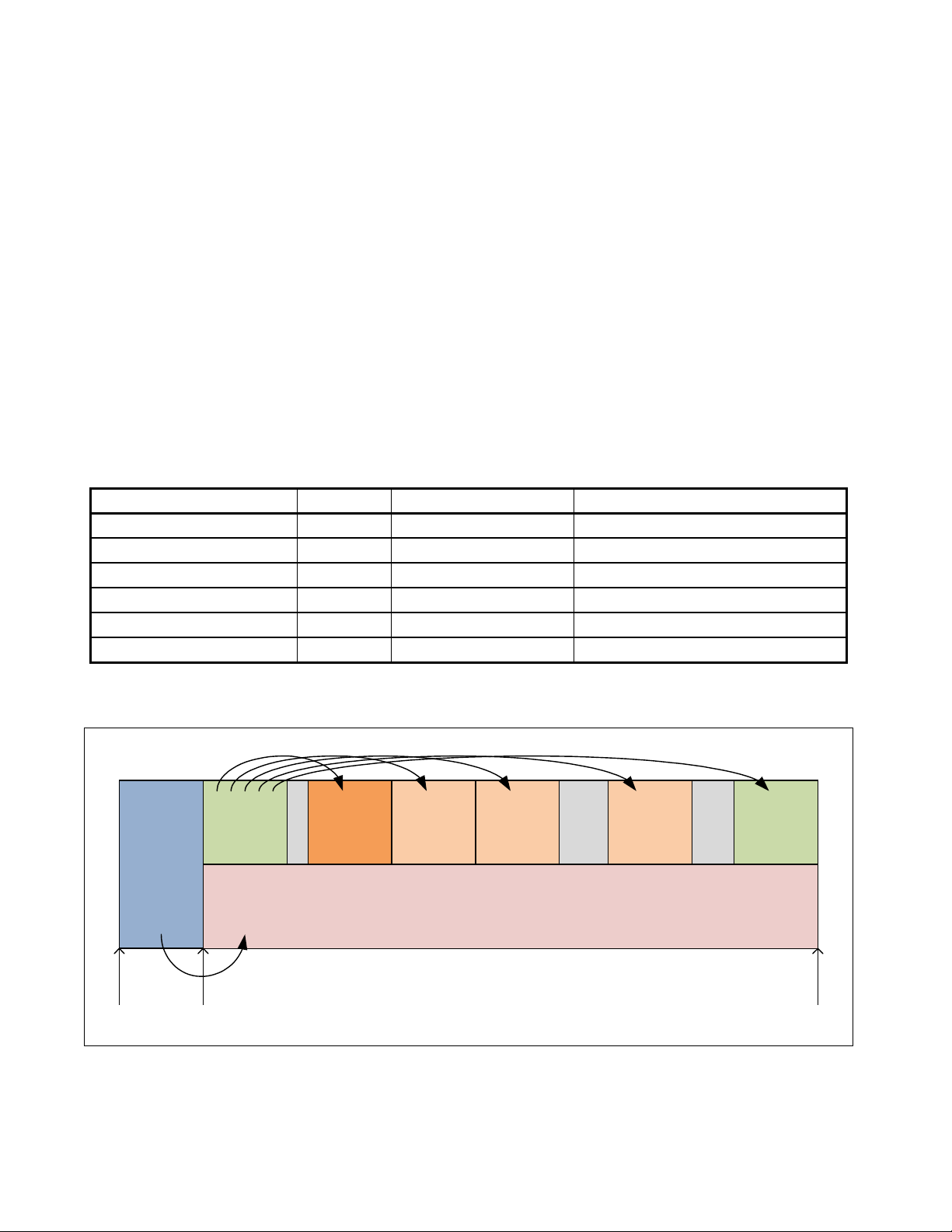
June 23, 2010 T13/2132-D Revision 3
Protective
MBR with
hybrid
MBR boot
code
Primary
GPT
UEFI
system
partition
Partition Partition
Backup
GPT
Partition
GPT Protective partition
LBA 0 LBA 1 End of disk
Annex A
(informative)
Hybrid MBR boot
A.1 Hybrid MBR boot overview
This annex describes how MBR boot code called hybrid MBR boot code may be constructed to support a GPT
disk layout (see UEFI-2.3) in a legacy BIOS system.
A.2 GPT support for hybrid MBR boot code
When using hybrid MBR boot code, the GPT disk layout includes one GPT partition with the Legacy BIOS
Bootable bit set to one in the Attributes field (see UEFI-2.3).
The Protective MBR defined in UEFI-2.3 is modified as shown in table A.1 to include hybrid MBR boot code.
Table A.1 — Protective MBR with hybrid MBR boot code
Mnemonic Byte Offset Byte Length Contents
Boot Code 0 440 Hybrid MBR boot code (see A.3)
Unique MBR Disk Signature 440 4 See UEFI-2.3
Unknown 444 2 See UEFI-2.3
Partition Record 446 16 * 4 See UEFI-2.3
Signature 510 2 See UEFI-2.3
Reserved 512 Logical Block Size - 512 See UEFI-2.3
Figure A.1 shows an example of a GPT disk layout with hybrid MBR boot code.
Working Draft Enhanced Disk Drive - 4 (EDD-4) 71
Figure A.1 — GPT disk layout with hybrid MBR boot code example
Page 84

T13/2132-D Revision 3 June 23, 2010
Protective
MBR with
hybrid
MBR boot
code
Primary
GPT
UEFI
system
partition
Partition Partition
Backup
GPT
Partition
GPT Protective partition
LBA 0 LBA FFFFFFFFhLBA 1 End of disk
LBAs not covered by
MBR data structures
Figure A.2 shows an example of a GPT disk layout with hybrid MBR boot code on a disk with an ending LBA
greater than FFFF_FFFFh. The MBR partition record is not able to describe the LBAs above FFFF_FFFFh.
Figure A.2 — GPT disk layout with hybrid MBR boot code truncation example
A.3 Hybrid MBR boot code
Hybrid MBR boot code performs the following steps:
1) use the Extended Read function (i.e., INT 13h FN 42h) (see 8.15) to load the Primary GPT Header. The
Device Address Packet (see table 9) includes:
A) the LBA field set to 00000000 00000001h; and
B) the Number of Blocks field set to 01h;
2) calculate the CRC32 of the GPT Header and verify that it equals the Header CRC32 field;
3) if the Header CRC32 field is incorrect, use the Extended Read function to load the backup GPT Header.
The Device Address Packet includes:
A) the LBA field set to the last LBA of the disk; and
B) the Number of Blocks field set to 01h;
NOTE 3 — Due to the limited size (i.e., 440 bytes) of the MBR boot code, the hybrid MBR boot code
may not perform all the checks that EFI system firmware would perform.
4) use the Extended Read function to load the GPT Partition Entry Array pointed to by the selected GPT
Header. The Device Address Packet includes:
A) the LBA field set to the value specified in the Partition Entry LBA field; and
B) the Number of Blocks field set to (Number Of Partition Entries * Size Of Partition Entry) / Logical
Block Size;
5) calculate the CRC32 of the GPT Partition Entry Array and verify that it equals the Partition Entry Array
CRC32 field in the GPT Header;
6) if the Partition Entry Array CRC32 field is incorrect and the Primary GPT Partition Entry Array was
selected, use the Extended Read function to load the backup GPT Header from the last LBA of the disk
(see step 3), load the backup GPT Partition Entry Array (see step 4), and calculate the CRC32
(see step 5). If the CRC32 is incorrect again, report an error and stop;
7) search the GPT Partition Entry Array for a partition with the Legacy BIOS Bootable bit set to one in the
Attributes field. The code may also check for a special value in the Partition Type GUID field when
selecting the partition;
8) use the Extended Read function to load the first logical block of the selected partition into memory
address 7C00h; and
72 Working Draft Enhanced Disk Drive - 4 (EDD-4)
Page 85

June 23, 2010 T13/2132-D Revision 3
9) set the IA-32 registers according to the hybrid MBR boot code hand over procedure (see A.4) and jump
to 7C00h.
NOTE 4 — In contrast, legacy MBR boot code searches the MBR Partition Records for a partition
with the Boot Indicator field set to 80h, then loads the VBR based on the Starting LBA field and
passes the Size In LBA field to the VBR.
A.4 Hybrid MBR boot code endeavor procedure
Hybrid MBR boot code fills in the IA-32 registers according to table A.2 before jumping to 7C00h.
Table A.2 — Hybrid MBR endeavor IA-32 register values
Register Description Differences from legacy MBR hand over
DL Disk number No change
ES:DI Pointer to $PnP No change
EAX 54504721h (i.e., "!GPT"). Indicates that the hybrid
MBR hand over structure is being passed with
DS:SI rather than the legacy MBR Partition Record
DS:SI Pointer to the hybrid MBR hand over structure (see
table A.3)
New
New
Table A.3 defines the Hybrid MBR boot code hand over structure.
NOTE 5 — With legacy MBR boot code, this structure included fields from the MBR Partition Record
of the boot partition. Since the GPT partition may be located at an LBA beyond the 32-bit LBA
addressing boundary, additional fields are added to communicate the full information to the VBR.
Table A.3 — Hybrid MBR boot code hand over structure
Byte
Mnemonic
Boot Indicator 0 1 Set to 80h (i.e., bootable). Fixed value
Starting CHS 1 3 Set to FF_FFFFh. The VBR boot code
OS Type 4 1 Set to the OS Type of the bootable
Ending CHS 5 3 Set to FF_FFFFh. The VBR boot code
Starting LBA 8 4 Set to FFFF_FFFFh. Fixed value
Size In LBA 12 4 Set to FFFF_FFFFh. Fixed value
Size Of Partition Entry 16 4 Set to the Size Of Partition Entry field of
GPT Partition Entry 20 Partition
Offset
Byte
Length Description
should ignore this field.
partition (i.e., that would have been
assigned had the partition been
installed in an MBR disk layout).
should ignore this field.
the GPT Partition Header.
Set to the GPT Partition Entry of the
Entry
Size
boot partition
Differences from legacy
MBR hand over structure
Fixed value
No change
Fixed value
New value
New value
Working Draft Enhanced Disk Drive - 4 (EDD-4) 73
Page 86

T13/2132-D Revision 3 June 23, 2010
A.5 Hybrid VBR boot code
Hybrid VBR boot code is responsible for booting the OS, and is usually OS-specific. If EAX is set to "!GPT", then
hybrid VBR boot code uses the GPT Partition Entry field to identify its partition.
NOTE 6 — In contrast, legacy VBR boot code only recognizes the MBR disk layout and uses the
Starting LBA field and Size In LBA field to identify its partition.
74 Working Draft Enhanced Disk Drive - 4 (EDD-4)
 Loading...