

Western Co. WR 10, WR 20, WR 30 User Manual [ml]
M
Vmp Vmp Vmp
A
N
U
A
L
E
U
T
E
N
T
E
W
R
1
0
/
2
0
/
3
0
M
A
N
U
A
L
E
U
T
E
N
T
E
W
R
1
0
/
2
M
A
N
U
A
L
E
U
T
E
N
T
E
0
W
R
1
0
/
2
0
/
3
0
/
3
0
I
T
V
1
.
3
I
T
V
1
.
3
I
T
V
1
.
3
REGOLATORE DI CARICA BATTERIA DA MODULO
FOTOVOLATICO
WR 10/20/30
Recapito:
WESTERN CO. srl
6307 4 San Be nedetto del Tro nto (AP)
tel 0735 751248 fax 0735 751254
Via Pasubio 1
e-mail: info@western.it
web: www.western.it
Caratteristiche
WR10/20/30 è un regolatore di carica da m oduli fotovoltaici per batterie elettriche
che può essere impiegato in piccoli o grandi impianti per uso domestico,
industriale o impianti di telecomunicazioni. Esso controlla la corrente del modulo
fotovoltaico con la tecnica chiamata PWM e controlla la scarica della batteria
distaccando il carico in caso di scarica profonda della batteria. Il carico può essere
attivato secondo diversi programmi selezionabili dall’utente: carico sempre
acceso, carico acceso solo di giorno, carico acceso solo di notte, carico acceso
solo di notte configurabile per un num ero di ore compreso da 1 a 16. I vari
programmi di gestione carico rendono il WR10/20/30 la soluzione com pleta in
molte applicazioni fotovoltaiche; ad esempio per alimentare telecamere che
debbono funzionare solo di giorno, oppure per alimentare lampeggiatori o
segnalazioni stradali che debbono funzionare solo di notte o per alimentare sistemi
di illuminazione che debbono funzionare per un determinato num ero di ore per
notte. Il WR10/20/30 rileva lo stato giorno/not te in base alla tensione di modulo;
quindi non è necessario collegare ulteriori sensori al regolatore.
Sono disponibili tre versioni: WR10, WR20 e WR30 rispettivamente per correnti di
modulo PV massimo 10A (WR10), 20A (WR20) e 30A (WR30). Quando in questo
manuale scriviamo WR10/20/30 significa che ci riferiamo a tutte e tre le versioni.
La tensione di ricarica è compensata in temperatura in modo da caricare batterie
anche in condizioni di temperatura estreme (da -10 a 60 °C) senza
comprometterne la vita utile. Si possono impostare programmi di carica per
batteria ermetiche/gel (SEAL) o per batteria ad acido libero (FLOOD). In fig 5 sono
riportate le tensioni di ricarica in funzione della temperatura per i due progra mmi
impostabili. E’ obbligatorio verificare nel manuale della propria batteria il
programma di ricarica più adeguato.
La batteria può avere tensione n ominale sia 12V che 24V; alla prima connessione
il WR10/20/30 misura la tensione di batteria e se questa è maggiore di 18V
imposta i programmi di ricarica per batteria a 24V, mentre se è inferiore ai 18V
imposta il programma di ricarica per batterie a 12V.
Il circuito è realizzato interamente con componenti allo stato solido (MOSFET);
quindi rispetto ad analoghi prodotti realizzati con componenti elettromeccanici
garantiamo una maggiore affidabilità nel tempo.
Il circuito ha le seguenti protezioni:
Inversione di polarità della batteria: se si invertono i morsetti di batteria il
WR10/20/30 non alimenta il carico, disabilita la carica della batteria e segnala
all’operatore un errore.
Corrente inversa sul modulo fotovoltaico: durante la notte, quando il m odulo
fotovoltaico non produce corrente, il regolatore WR10/20/30 ha internamente un
diodo di blocco che evita la scarica della batteria verso il modulo fotovoltaico.
Low-battery: Quando la tensione di batteria scende sotto la soglia Vlb (impostabile
dall’utente) il WR10/20/30 toglie l’alimentazione sulla sua uscita LOAD in modo da
proteggere la batteria da scariche profonde.
Cortocircuito sul carico: qualora la corrente sul carico superi il valore nominale pari
a 10,0A per il W R10, 20,0A per il WR20 e 30,0A per il WR30 per più di 0,5 secondi
il regolatore distacca il carico.
Sovra-temperatura: quando la temperatura interna
supera gli 80°C vengono distaccati sia il m odulo PV sia
il carico i n modo da evitare che l’eccessivo
surriscaldamento porti a rottura del circuito.
Sovraccarico da modulo PV : se la corrente dal m odulo
supera il valore massimo consentito (10,0A per il
WR10, 20,0A per il WR20 e 30,0A per il WR30) si
disabilita la ricarica a protezione del circuito interno.
Installazione
Per un corretto smaltimento del calore prodotto,
specialmente quando il WR10/20/30 lavora ad elevate
correnti, bisogna installarlo in modo da non ostruire la
circolazione d’aria sottostante il regolatore.
Il WR10/20/30 va fissato su una parete verticale o su di una superficie orizzontale
di tipo non infiamm abile e protetto dall’umidità; quindi non può essere installato in
ambiente esterno. Per installazioni all’esterno il WR10/20/30 va alloggiato in una
adeguata cassetta protetta all’acqua e all’umidità, meglio se metallica in modo che
possa smaltire il calore prodotto.
Il regolatore va posto il più vicino possibile alla batteria in modo da rendere i cavi
più corti possibile. La sezione dei cavi deve essere scelta in modo da evitare che
durante il funzionamento del sistema questi si surriscaldino. Per moduli PV con
correnti maggiori
di 10A consigliam o
l’uso di sezioni di
cavo di 10mm
per moduli PV da
5A a 10A
2
,
consigliamo la
sezione di cavo di
2
6mm
e per moduli
PV con corrente
inferiore a 5A
consigliamo la
sezione di 4mm
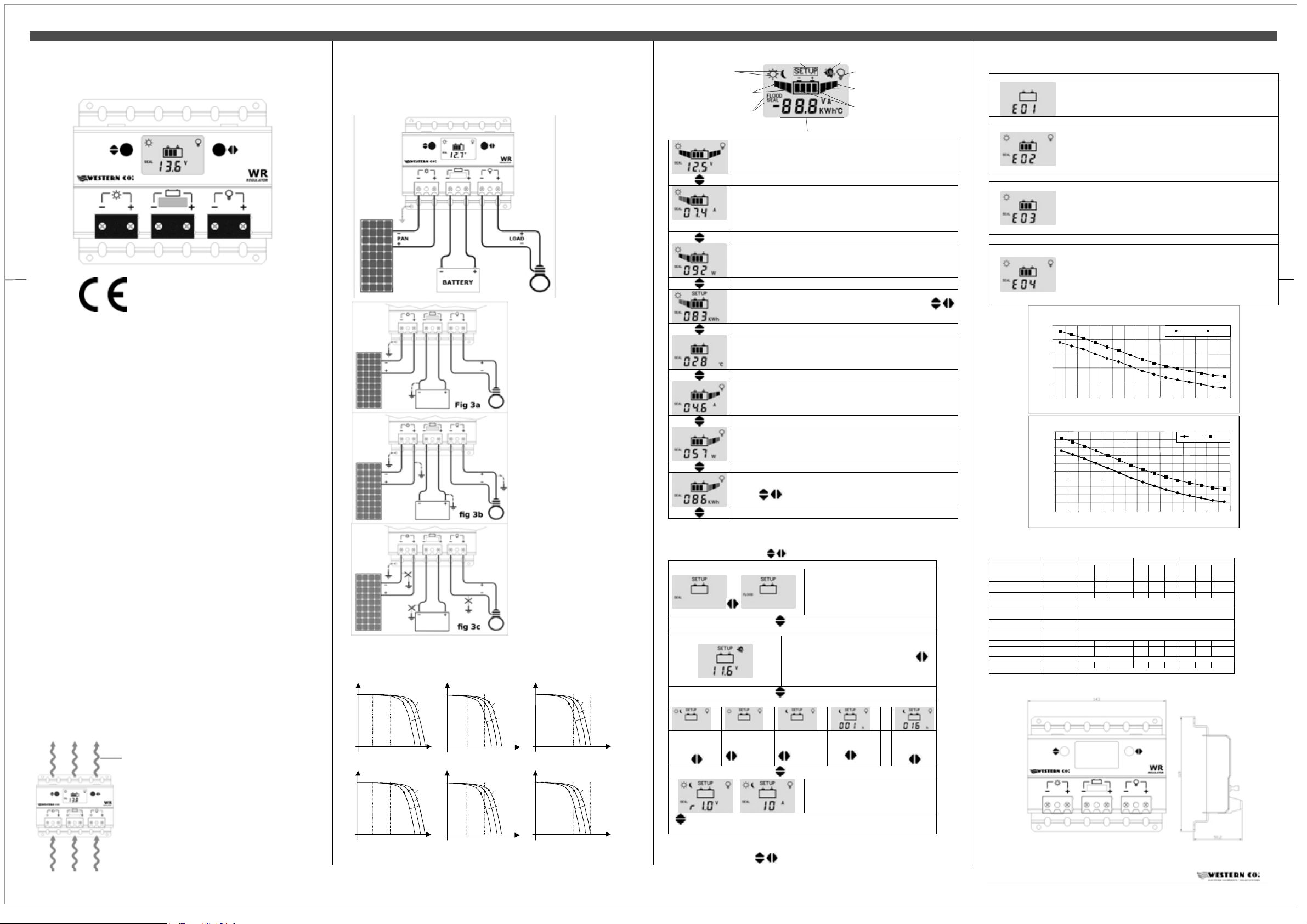
In fig. 2 è riportato
lo schema di
elettrico del
WR10/20/30. Il
collegamento della
Fig 2
per una più efficace protezione
alle scariche atmosferiche.
Qualora sia richiesto di
connettere un morsetto della
batteria alla terra è possibile farlo
come in fig 3a; é possibile
connettere insieme alla terra i
morsetti +PAN, +BATT e +LOAD
come in fig 3b, non è invece
possibile connettere la terra come
carcassa alla terra
non è obbligatorio,
ma è consigliato
collegamento
2
.
in fig 3c.
Il modulo PV da collegare al
regolatore WR10/20/30 va scelto
rispettando i seguenti criteri:
-La corrente di cortocircuito (Isc)
del modulo PV non deve
superare la corrente nominale
10A per il WR10, 20A per il
WR20 e 30A per il WR30.
-La tensione a circuito aperto Voc
del modulo PV va scelta in base
alla tensione della batteria da
ricaricare. Quando una batteria è
in carica la sua tensione varia da
11.0V a 14.4V per sistemi a 12V
e da 22.0V a 28.8V per batteria a
24V. Il modulo PV va scelto in
modo che la sua tensione di
massima potenza Vmp sia circa
uguale alla massima tensione di
batteria fig. 4b e 4e. Qualora si
scelga un modulo con una Vmp
molto maggiore della massima
tensione di batteria (fig. 4a e 4d)
si rischia di non sfruttare tutta la
potenza del modulo PV. Invece
se la Vmp è scelta troppo piccola
della tensione di batteria (fig. 4c e 4f) si rischia che la batteria non riuscirà mai a
caricarsi alla sua massima tensione.
Ipan
Ipan
Vbatt
11V
Vbatt
22V
NO
Vbatt
14.5V
fig. 4a
NO
Vbatt
28.8V
fig. 4d
Vmp
Ipan Ipan
T25°C
T35°C
T55°C
Vpan
Ipan Ipan
T25°C
T35°C
T55°C
Vpan
OK
Vbatt
Vbatt
11V
14.5V
fig. 4b
OK
Vmp
Vbatt
Vbatt
22V
28.8V
fig. 4e fig. 4f
rispetto l’intervallo di variazione
NO
Vbatt
11V
Vbatt
22V
fig. 4c
NO
Vmp
T25°C
T35°C
T55°C
Vbatt
14.5V
T25°C
T35°C
T55°C
Vbatt
28.8V
T25°C
T35°C
T55°C
Vpan Vpan
T25°C
T35°C
T55°C
Vpan Vpan
Funzionamento del sistema
Visualizzato nelle sole schermate di configurazione
Stato giorno/notte
Indicazio ne assorbimento
corrente dal pan nello PV
Indica quale programma di
ricarica è at tualmente impo stato
Pagina principale.
Visualizza la tensione di batteria, lo stato giorno/notte rilevato dal modulo
PV, l’icona del carico se accesa indica che il carico è alimentato ed è
visualizzato il programma di ricarica attualmente selezionato.
Visualizza la corrente del modulo PV. Ricordiamo che la corrente erogata
dal modulo PV dipende dallo stato di soleggiamento dello stesso e dallo
stato di carica della batteria. Con la batteria carica (Vbatt>14,4V @12V o
Vbatt>28,8V @24V) anche con un buon soleggiamento del modulo si
hanno correnti di ricarica basse in quanto è il regolatore che limita tale
corrente per evitare sovraccarico della batteria.
Visualizza la potenza in watt attualmente erogata dal modulo PV.
Visualizza il contatore dell’energia erogata dal modulo in KWh. E’ possibile
azzerare questa misura premendo contemporaneamente i pulsanti
per 2 secondi.
Visualizza la temperatura della batteria attualmente misurata dalla sonda
interna al WR10/20/30.
Visualizza la corrente attualmente erogata al carico; anche se in questa
schermata compare accesa l’icona del carico non è detto che questo sia
effettivamente alimentato, infatti il carico è controllato secondo il
programma di gestione carico attualmente impostato .
Visualizza la potenza attualmente erogata al carico in watt.
E’ visualizzato il contatore dell’energia in KWh consumati dal carico. E’
possibile azzerare questo contatore premendo contemporaneamente i
pulsanti per 2 secondi.
Alla pressione del tasto sinistro si ritorna alla pagina principale.
Visualizza le misure interne
Protezione bat teria scarica attiva
Accensione carico
Indicazione assorbimento
corrente sul carico
Livello di tensione nella b atteria
Configurazione del sistema
Si accede alle pagine di configurazione del W R10/20/30 mantenendo premuti per
almeno 2 secondi i pulsanti
Pagina configurazione programma di ricar ica
Pagina Configurazione tensione di Low Ba ttery
Pagina Configura zione progra mma gestione carico
carico sempre
acceso sia di
giorno che di
notte.
Una volta modificate le im postazioni del WR10/20/30 queste diventano operative
solo dopo essere usciti dalla pagine di configurazione mantenendo premuti per
carico acceso
solo di giorno.
Alla pressione del tasto sinistro si ritorna nella pagina configurazione programma di
.
Imposta il programma di ricarica per la
batteria.
Si consiglia di impostare il programma
SEAL per batterie ermetiche o al gel,
invece il programma FLOOD per la
ricarica di batteria ad acido libero.
cambio pagina
Imposta la tensione di intervento della protezione
di Low battery (distacco del carico in caso di
batteria scarica). Alla pressione del tasto si
modifica l’impostazione da 10.8V a 12.2V per
sistemi a 12V e da 21.6V a 24.4V per sistemi a
24V.
cambio pagina
.
carico acceso
solo di notte.
cambio pagina
ricarica
carico acceso
di notte per 1
ora.
Visualizza alternativamente la versione
software e la versione 10A, 20A e 30A del
regolatore.
carico
acceso di
notte per 16
ore.
Codici di errore
All’intervento delle protezioni interne del W R10/20/30 compaiono dei codici di
errore come riportato di seguito.
16,00
15,50
15,00
14,50
14,00
Tensione fina carica Volt
13,50
-10 -5 0 5 10 15 20 25 30 35 40 45 50 55 60
Tensione fine carica in funzione della temperatura
32,00
31,50
31,00
30,50
30,00
29,50
29,00
28,50
Tension e fina cari ca Volt
28,00
27,50
27,00
-10 -5 0 5 10 15 20 25 30 35 40 45 50 55 60
Tabella codice errore
E’ stata connessa la batteria con polarità invertite. Rivedere il
collegamento elettrico della batteria.
Interviene quando la temperatura interna del WR10/20/30 supera gli
80°C e disattiva la ricarica. Si esce automaticamente da questa
protezione quando la temperatura interna scende al di sotto della
soglia di 50°C (nota: la temperatura interna al regolatore non è
visualizzata nell’LCD). Qualora intervenga spesso questa protezione
consigliamo di alloggiare il regolatore in un luogo più fresco.
Intervenuta protezione di sovraccarico. La corrente del carico ha
superato il limite massimo consentito per il WR10/20/30 (Iload nella
tabella caratteristiche elettriche) e il regolatore ha distaccato il carico
per prevenire rotture interne. Nel caso intervenga questa
segnalazione è necessario verificare se la corrente assorbita dal
carico è inferiore al limite consentito. Dopo 1 minuto il WR10/20/30
alimenta nuovamente il carico.
La corrente del modulo ha superato la massima corrente consentita
(Ipan nella tabella caratteristiche elettriche) e il WR10/20/30 ha
disabilitato la ricarica per prevenire rotture interne. Dopo circa 1
minuto il WR10/20/30 riattiva la ricarica automaticamente. Questa
protezione interviene qualora si connetta al regolatore un modulo PV
con una corrente troppo elevata (Isc del modulo supera la Ipan sulla
tabella caratteristiche elettriche), quindi qualora intervenga questa
protezione è necessario scegliere un differente modulo.
Tensione fi ne carica in fun zione della temperatu ra
sistema a 12V
Temperatura °C
sistema a 24V
Temperatura °C
fig. 5
SEAL FLOOD
SEAL FLOOD
CARATTERISTICHE ELETTRICHE
WR10 WR20 WR30
Tensione di bat teria Vbatt [V] 10 - 35 10 35 10 35
Tensione di modulo Vpan [V] - - 55 - - 55 - - 55
Corrente di modul o Ipan [A] - - 10 - - 20 - - 30
Corrente del c arico Iload [A] - - 10 - - 20 - - 30
Tensione di r icarica
@ 25°C SEAL
Tensione di r icarica
@ 25°C FLOOD
Protezione b atteria
scaric a
Soglia ri pristino da
batteria sc arica
Auto consumo Islee p [mA] 8,0 8,0 8,0
Temperatura di
esercizi o
Potenza dissip ata Pdiss 6.8W @10A 8.0W @20A 16.0W @30A
Sezione ai morset ti mm2 1 - 10 1 - 10 1 - 10
Grado di protezi one IP20
Vch 14.4V @12V
Vch 14.8V @12V
Vlb impostabile da 10. 8V a 12.2V @12V
VexLb Vch – 1V @ 12V
Tamb °C - 10 - 60 -10 - 60 -10 . 60
Min Tip M ax Min Tip Max Min Tip Max
28.8V @24V
29.6V @24V
impostabile da 2 1.6V a 24.4V @24V
Vch – 2V @ 24V
Dimensioni
almeno 2 secondi i tasti .
Questo doc umento é proprietà riservata dalla WESTER N CO. Srl. E’ vieta ta la riproduzione di
informazi oni contenute i n questo document o senza consenso scr itto della WESTER N CO. Srl.
1
U
Vmp
Vmp Vmp
Vmp
Vmp
Vmp
p
S
E
R
M
A
N
U
A
L
W
R
1
0
/
2
0
/
3
0
U
S
E
R
M
A
N
U
A
L
W
R
U
S
E
R
M
A
N
U
1
A
L
W
R
0
/
2
0
/
3
0
1
0
/
2
0
/
3
0
E
N
V
1
.
3
E
N
V
1
.
3
E
N
V
1
.
3
PHOTOVOLTAIC BATTERY CHARGE REGULATOR
WR 10/20/30
Address:
WESTERN CO. Srl
63074 San Benedetto del Tronto (AP) - Italy
tel +39 0735 751248 fax +39 0735 751254
Features
WR10/20/30 is a charge regulator from PV modules for electric batteries. It can be
used either in small or i n big systems for homes, industries or telecommunication
systems. It controls the PV module current with PW M and the battery discharge b y
disconnecting the load in case of deep discharge of the battery. The load can be
activated according to different programs which can be set by the user: load
always ON, load ON only during the day, load ON only during night, load ON only
during night and configurable for a number of hours included from 1 t o 16. T he
different programs of load management make WR10/20/30 the complete solution
in many PV applications; for example: to power supply video cameras that have to
work only during da y, to power sup ply flashing systems or road signalling systems
that have to work only during night, to power supply lighting s ystems that have to
work for a specified number of hours per night. WR10/20/30 notes the day/night
status according to the PV module voltage; therefore it is not necessary to connect
further sensors to the regulator.
There are 3 versions: WR10, WR20 and W R30 respectively for PV module
currents of max 10A (WR10), 20A (WR20) and 30A (WR30). In this manual when
we write WR10/20/30 we refere to all versions WR10, WR20 and WR30.
The charge voltage is com pensated in temperature so to charge the batteries even
with extreme temperature conditions (from -10 to 60 °C) without compromising the
useful life. You can set charg e programs either for GEL/AGM sealed batteries
(SEAL) or for flooded lead acid batteries (FLOOD). In fig. 5 there are the charge
voltages according to the temperature for the two programs that can be set. It is
compulsory to verify in the technical m anual of your batter y if the charging voltage
is appropriate to the battery.
The battery can have a nominal voltage either 12V or 24 V; at its first starting
WR10/20/30 measures the battery voltage and, if it is > of 18V, it sets the charge
program for 24V battery, while if it is < of 18V it sets the charge program for 12V
battery.
The internal circuit is completely made with solid state components (MOSFET);
therefore in comparison with similar products having electro-mechanical
components, we guarant ee a greater reliability in time.
The circuit has got the following protections:
Polarity inversion of battery: if you invert the battery terminals, WR10/20/30 does
not power on, it does not power the load and it signals a mistake to the operator.
Revers current on PV modules: during night, when PV module does not produce
current, WR10/20/30 charge regulator has an internal reverse current diode that
avoids the battery discharge towards the PV module.
Low-battery: When battery voltage drops below Vlb threshold (selectable)
WR10/20/30 charge regulator disconnects the load to protect the batt ery from
deep discharge.
Short-circuit on the load: If the current on load
overcomes the nominal value equal to 10,0 A for
WR10, 20,0A for W R20 and 30,0A for W R30 for more
than 0,5 seconds, the regulator disconnects the load.
Over-temperature: when the internal temperature
overcomes 80°C, both PV module and load are
disconnected so to avoid that excessive over-heating
provokes the breakage of the circuit.
Overload on PV module: if current from PV module
overcomes Ipan max the W R10/20/30 stops the
charge current to protect its internal circuit.
Installation
WR10/20/30 so not to obstruct the movement of air below the regulator, especially
when it works at high temperatures.
WR10/20/30 must be fixed either on a vertical wall or on an horizontal notflammable surface and protected against humidity; therefore it cannot be installed
For a right heat dissipation you have to install
Via Pasubio 1
e-mail: info@western.it
web: www.western.it
in outdoor applications. For outdoor applications WR10/20/30 has to be housed in
a proper box that has to be protected against water and humidity, even better if the
box is metallic so to dissipate the produced heat.
The regulator has to be placed as close as possible to the battery so to make the
cables as short as possible. The cables’ section has to be chosen so to avoid that,
during the system working, they can go in overheating. For PV modules with
currents > of 10A
we advise the use
of cables section of
2
10mm
; for PV
modules from 5A
to 10A we advise
the use of cables
section of 6mm
and for PV
modules with
current < to 5A we
advise the use of
cables section of
2
4mm
.
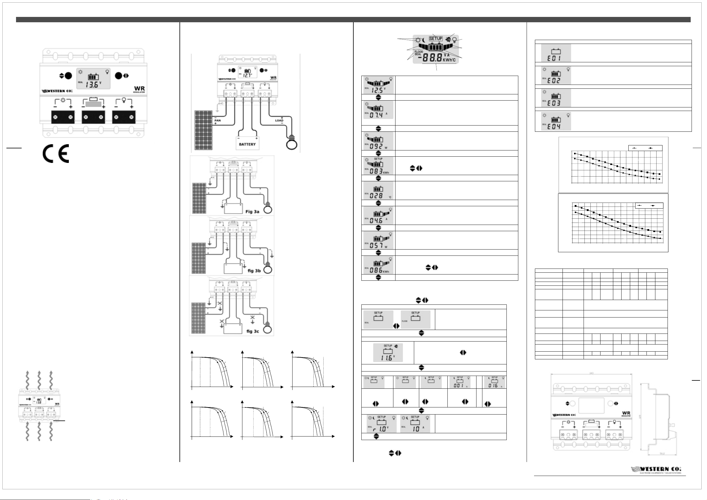
In fig. 2 there is the
scheme of electric
connection of
WR10/20/30. The
connection of the
Fig 2
case to the ground
is not compulsory,
but it is advised for
a more effective protection
against lightning.
If you have to connect a batter y
terminal on the ground you can do
it as in fig 3a; it is possible to
connect together on the ground
the connectors: +PAN, +BATT
and +LOAD as in fig 3b; on the
contrary, it is not possible to
connect the ground as in fig 3c.
The PV module that has to be
connected with W R10/20/30
regulator, has to be chosen by
respecting the following criteria:
-The short-circuit current (Isc) of
PV module must not overcome
the nominal current of 10A for
WR10, 20A for W R20 and 30A for
WR30.
-The open-circuit voltage (Voc) of
the PV module has to be chosen
according to the voltage of th e
battery that has to be charged .
When a battery is in charge its
voltage changes from 11.0V to
14.4V for systems @ 12V and
from 22.0V to 28.8V for batter y @
24V. The chosen PV module must
have its maximum power voltage
(Vmp) equal to the maximum
battery voltage (fig. 4b and 4e). If
you choose a module with a Vmp
much greater than the m aximum
battery voltage (fig. 4a and 4d)
you risk not to exploit the whole
PV module’s charge. Otherwise if
the chosen Vmp is too small in
comparison with the interval of
variation of the battery voltage (fig. 4c and 4f) you risk that the battery will not be
able to charge at its maximum voltage.
Ipan
Ipan
Vbatt
11V
Vbatt
22V
NO
Vbatt
14.5V
fig. 4a
NO
Vbatt
28.8V
fig. 4d
Ipan Ipa n
T25°C
T35°C
T55°C
Vpan
Ipan Ipa n
T25°C
T35°C
T55°C
Vpan
OK
Vbatt
Vbatt
11V
14.5V
fig. 4b
OK
Vbatt
Vbatt
22V
28.8V
fig. 4e fig. 4f
Vbatt
11V
Vbatt
22V
NO
fig. 4c
NO
T25°C
T35°C
T55°C
Vbatt
14.5V
T25°C
T35°C
T55°C
Vbatt
28.8V
T25°C
T35°C
T55°C
Vpan Vpan
T25°C
T35°C
T55°C
Vpan Vpan
System working
It is displaye d only in the configuration screens Low battery protection is active
Day/night status
Ind i ca t i on of cur r e n t
ti on fro m P V
ab s or
It in dicat es wh ich ch arge
program is actually set
Main page.
2
It shows the battery voltage, the day/night status taken from the PV
module. If the load icon is ON it means that the load is power supplied and
you can see the charge program currently selected.
It shows the current of PV module. We remember that the current delivered
by the PV module depends on its state of sun irradiation and on the battery
state of charge. In condition of charged battery (Vbatt>14,4V @12V or
Vbatt>28,8V @24V) even with a good sun irradiation of the module we
have low charge currents since the regulator limits such a current to avoid
a battery overcharge.
It shows the power in watt actually delivered by the PV m odule.
It displays the counter of energy that is delivered from the module in KWh.
It is possible to reset such measure by pushing at the same time the push-
buttons for 2 seconds
It displays the temperature of battery that is measured by the internal
sensor to WR10/20/30.
It displays the current actually delivered to the load; even if in this screen
there is the load icon ON, this does not mean that the load is not effectively
power supplied. In fact the load is controlled according to the program of
load management which is actually set.
It shows the power actually delivered to the load in watt.
Here you can see the counter of energy in KWh that have been consumed
by the load. It is possible to reset this counter by pressing at the same time
the push-buttons for 2 seconds.
When you press the left button you return to the main page.
It displays internal measures
Loa d Pow er o n
Indicati on of current
absorption on the load
Volt age l eve l in th e ba tter y
System configuration
You can access to the configuration pages of WR10/20/30 by pressing for at least
2 seconds the push-buttons
Configuration pa ge of charge program
Configuration page of Low Ba ttery vol tage
Configuration pa ge of load management pro gram
Load always ON
either during day
or during
night.
Load ON
only during
day
Press left button to go back to the configuration page of charge program.
.
It sets the charge program for the battery.
We advise to set the SEAL program for
PB sealed AGM / GEL batteri es, while we
advise to set the FLOOD program for the
charge of flooded lead acid batteries.
change of page
It sets the intervention voltage of Low Battery protection
(load disconnection in case of discharged battery). By
pressing the push-button you modify the setting
from 10.8V to 12.2V for systems @ 12V and from
21.6V to 24.4V for systems @ 24V.
change of page
.
Load ON only
during night
.
change of page
Load ON
during night for
1 hour .
It displays the software version and
ampere size of regulator (10A / 20A /
30A).
Load ON
during night
for 16 hours
Error code
When in WR10/20/30 an internal protection occurs, it is displayed the error c ode
(see table below).
You hav e connecte d the ba ttery with inverte d polariti es. Cont rol the wir ing.
It occurs when internal temperature of WR10/20/30 rises above 80°C. In this case
battery charge is disabled. You comes out automatically from this protection when
the temperature drops below the threshold of 50 ° C (internal temperature is not
displayed in the LCD). If this protection occurs often we suggest to install the
WR10/20/30 in a cooler place.
It occurred the overload protection. The load current has exceeded the maximum
limit allowed for the WR10/20/30 (Iload in table electric feature) and the regulator
has disconnected the load to prevent internal breaking. If you see this message you
should check if the current absorbed by the load is lesser than the permitted limit.
After 1 minute the W R10/20/30 power s upplies back the loa d.
The PV current has exceeded the maxi mum allowable current (Iload in table
electric feature) and the regulator has disconnected the PV to prevent internal
breaking. After about 1 minute WR10/20/30 re-activates the charge automatically.
You have this protection when you connect to the regulator a PV module with too
high c urrent (Isc of the PV module exceeds Ipan on the table of electrical features);
therefore you must choose a different PV module.
Error code table
Charge volt age Volt
Charge volt age Volt
Charge voltage To temperature for 12V battery
16,00
15,50
15,00
14,50
14,00
13,50
-10 -5 0 5 10 15 20 25 30 35 40 45 50 55 60
Charge voltage To temperature for 24V battery
32,00
31,50
31,00
30,50
30,00
29,50
29,00
28,50
28,00
27,50
27,00
-10 -5 0 5 10 15 20 25 30 35 40 45 50 55 60
Temper ature °C
Temperature °C
SEAL FLOOD
fig. 5
SEAL FLOOD
ELECTRIC FEATURES
WR10 WR20 WR30
Battery voltage
Module volt age
Module curre nt
Charge voltage
@ 25°C prog.
SEAL
Charge voltage
@ 25°C prog.
FLOOD
Threshold of low
batte ry protect ion
Threshold - exit
low battery
protection
Self-consumption
Worki ng
temperature
Dissipated power
Conduct ors
section
Box IP degree
Battery voltage
Vbatt [V] 10 - 35 10 35 10 35
Vpan [V] - - 55 - - 55 - - 55
Ipan [A] - - 10 - - 20 - - 30
Iload [A] - - 10 - - 20 - - 30
Vch 14.4V @12V
Vch 14.8V @12V
Vlb Settable from 10.8V to 12.2V @12V
VexLb Vch – 1V @ 12V
Isleep [mA] 8,0 8,0 8,0
Tamb °C - 10 - 60 -10 - 60 -10 . 60
Pdiss 6.8W @10A 8.0W @20A 16.0W @30A
mm
IP20
Min Typ Max Min Typ Max Min Typ Max
28.8V @24V
29.6V @24V
Settable fr om 21.6V to 24. 4V @24V
Vch – 2V @ 24V
2
1 - 10 1
- 10 1 - 10
Mechanical dimensions
Once you have modified the settings of W R10/20/30 these become operative only
after having left the configuration pages by pressing for at l east 2 seconds the
push-buttons
This document is the property of WESTERN CO. Srl. All rights are reserved.
Reproduct ion and use of informat ion contained w ithin this document is forbidden
without the written consent of WESTERN CO. Srl.
2
 Loading...