

Western Airconditioning Zeta Echos, Zeta Echos/HP, Zeta Echos/ST, Zeta Echo/LN, Zeta Echos/SLN Technical Information Manual
...Page 1
Western Airconditioning B.V. Tel. +31 (0) 33 247 78 00 www.western.nl
Zeta Echos
air/water chillers and heat pumps
Technical information manual
Page 2

Western Airconditioning B.V. reserves the right to alter specifications
2
ZETA ECHOS
Water chiller
ZETA ECHOS/HP
Reversible heat pump
ZETA ECHOS/ST
Unit with tank and pumps
ZETA ECHOS/DC
Unit with recovery condenser
ZETA ECHOS/DS
Unit with desuperheater
ZETA ECHO/LN
Low-noise unit
ZETA ECHOS/SLN
Super low-noise unit
ZETA ECHOS/LE
Motocondensing unit
ZETA ECHOS A
High performance unit
Page 3

Western Airconditioning B.V. reserves the right to alter specifications
3
Index
Technical features 4
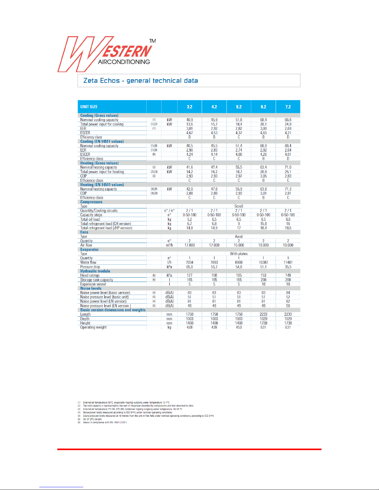
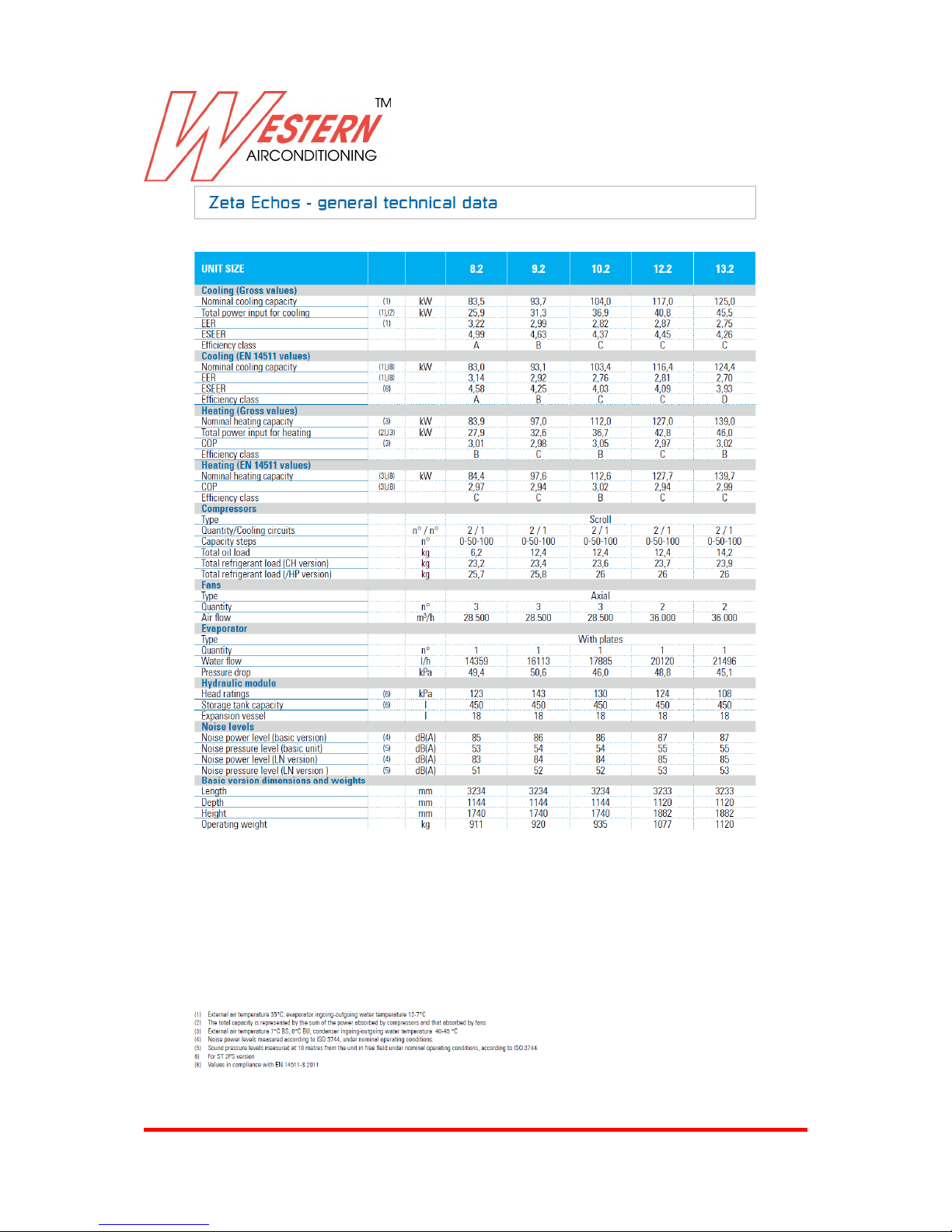
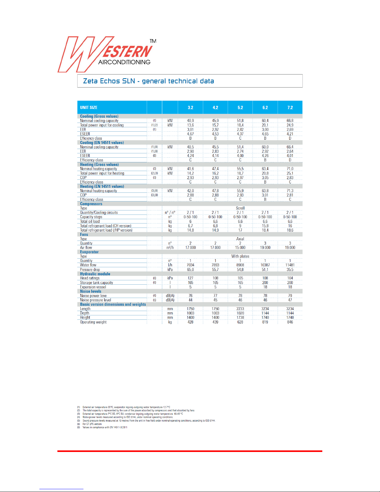
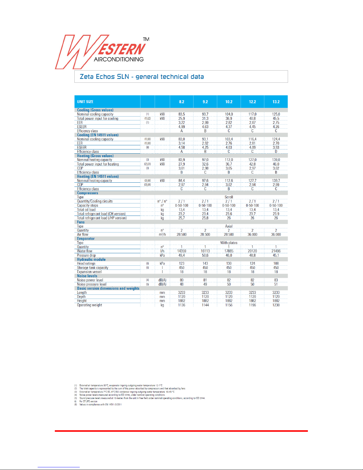
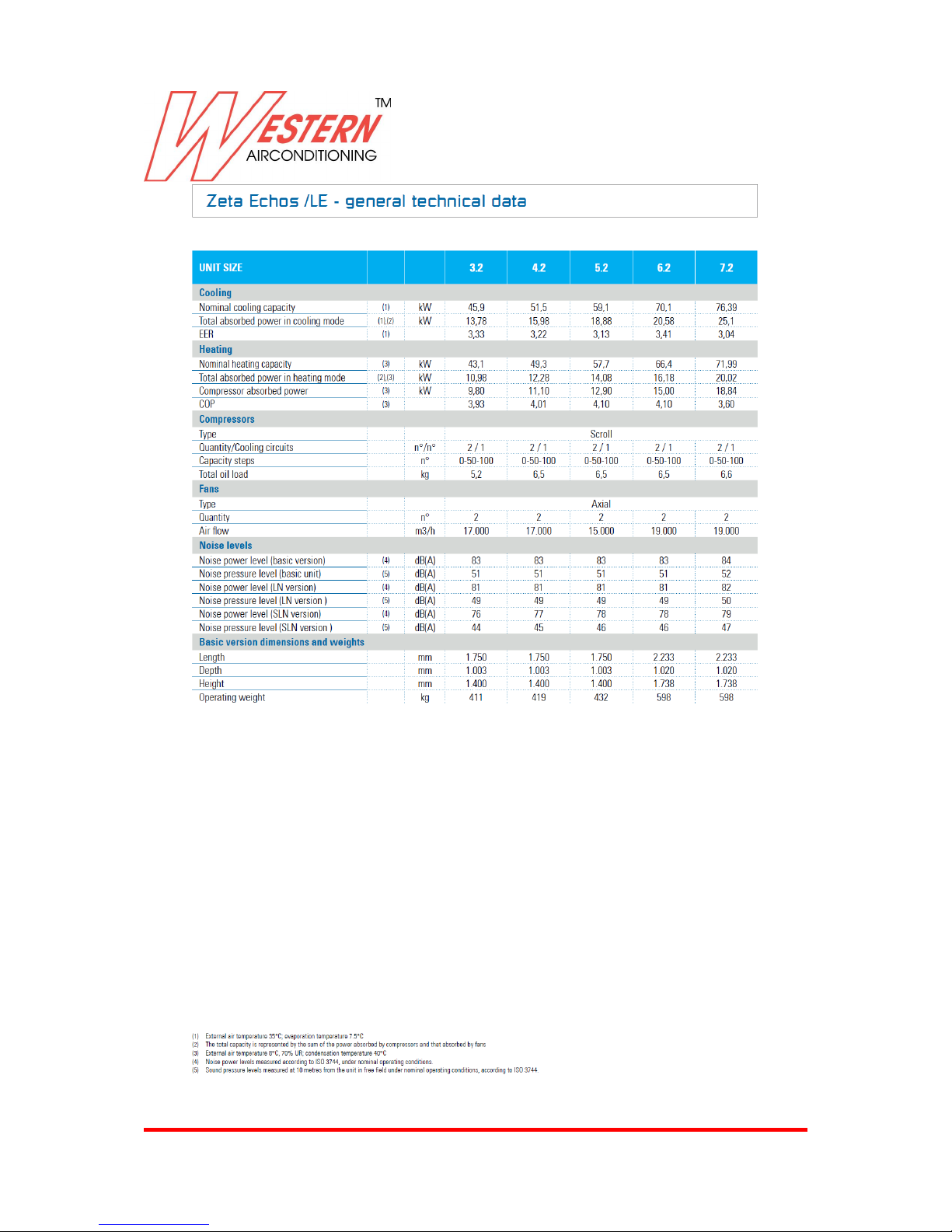
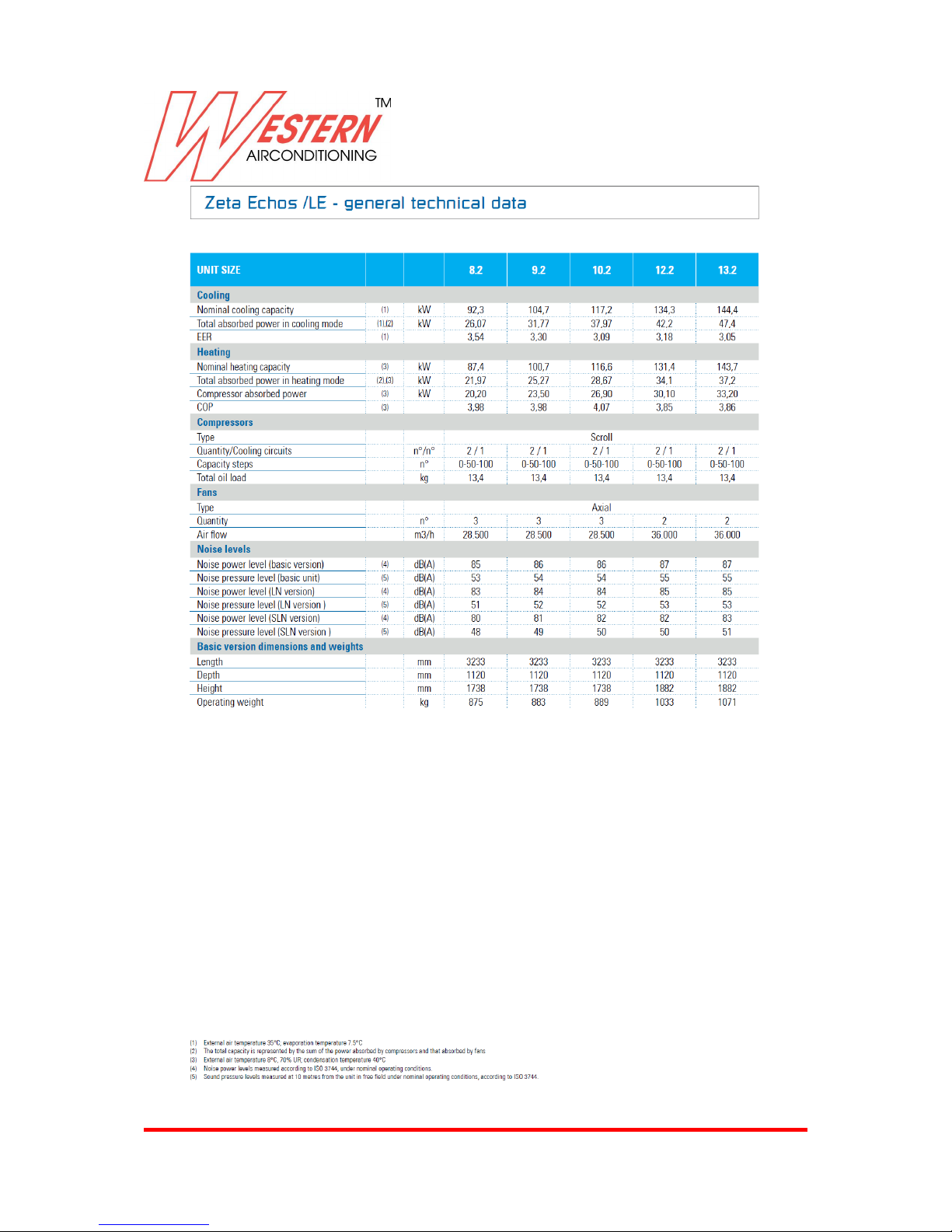
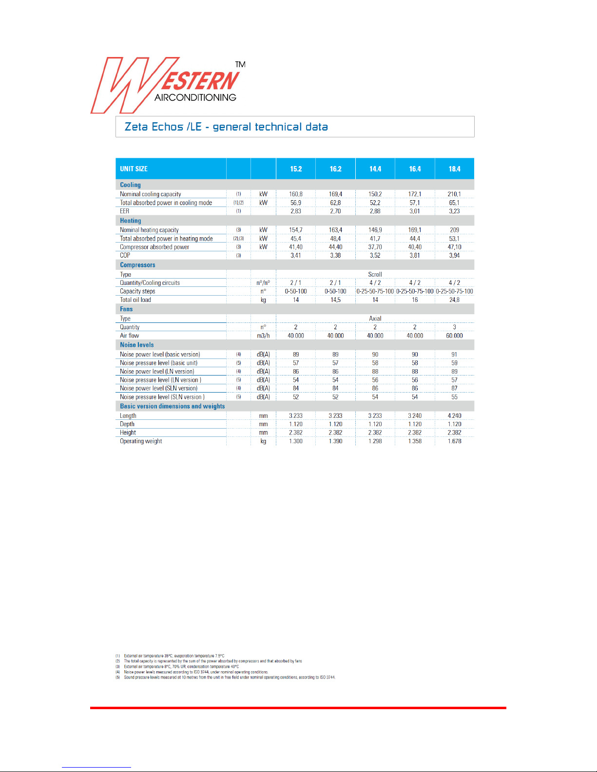
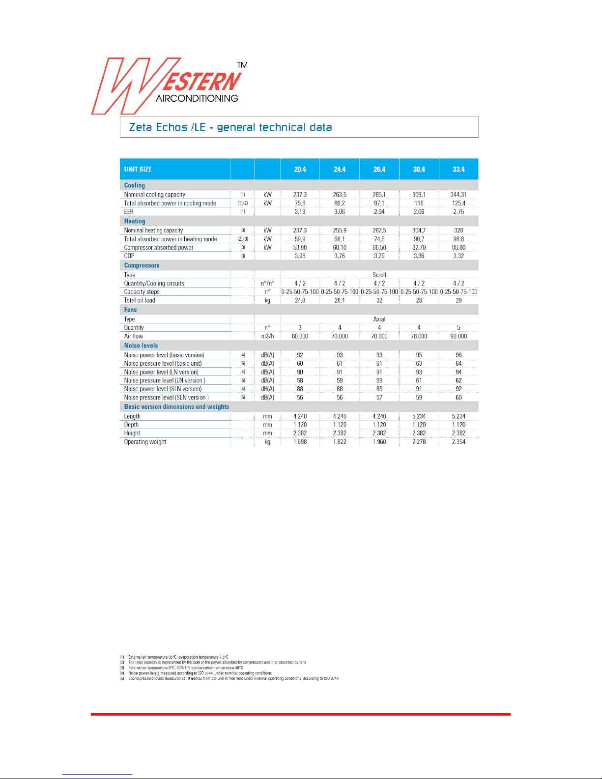
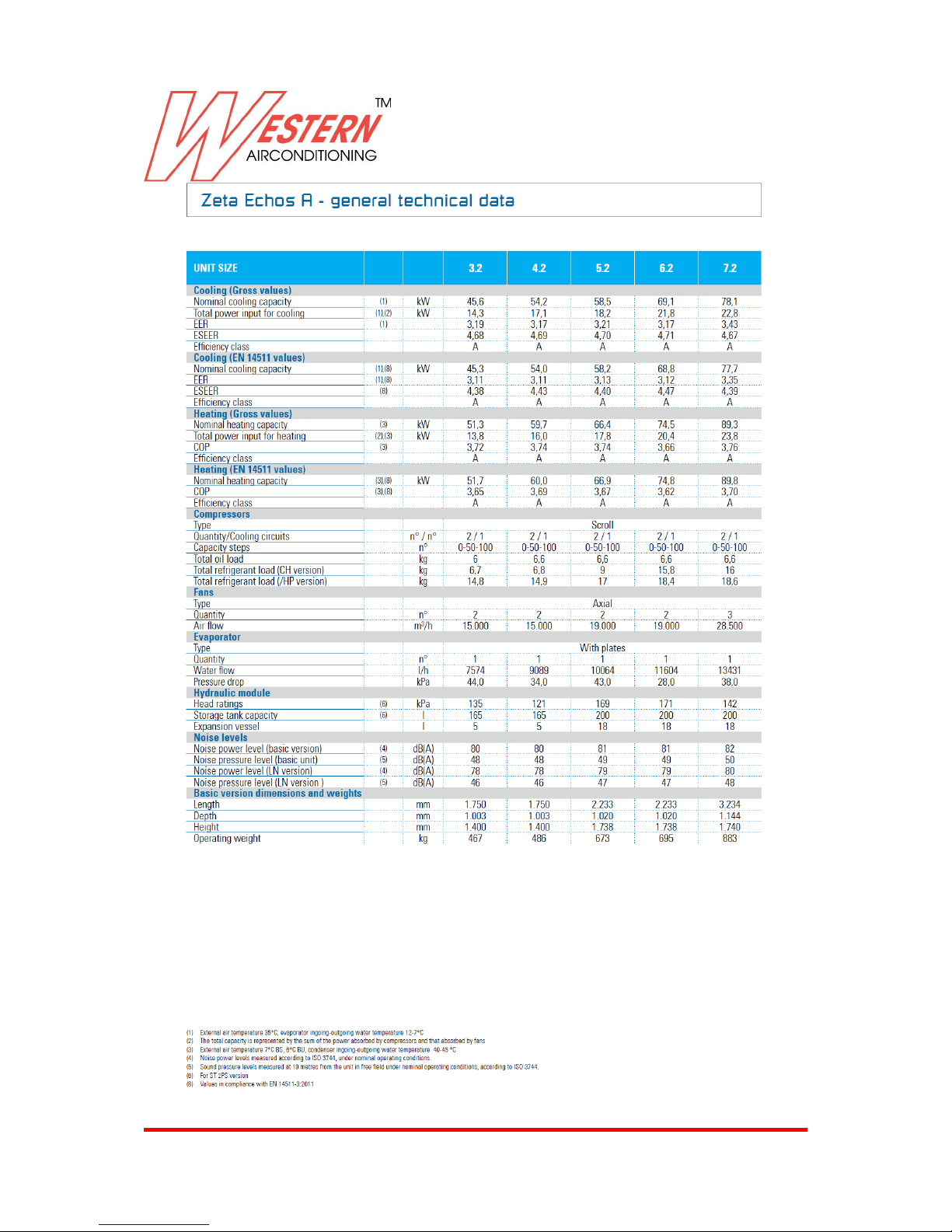
General technical data 16
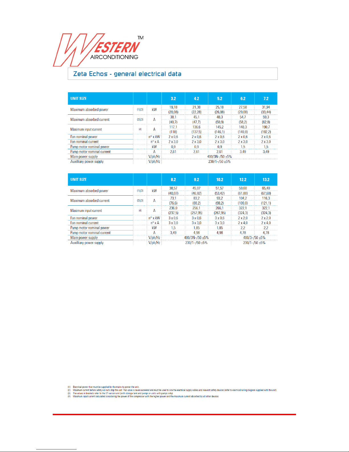
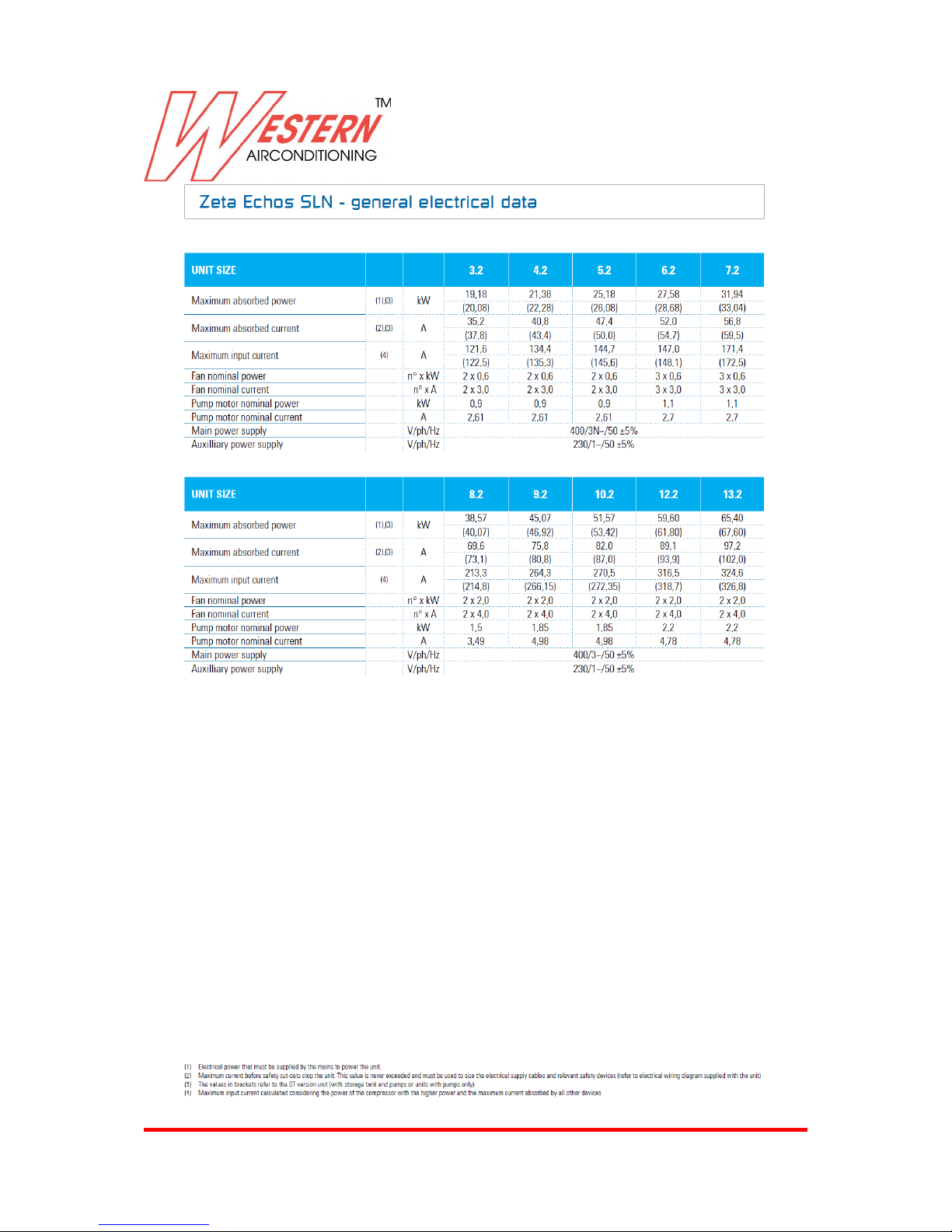
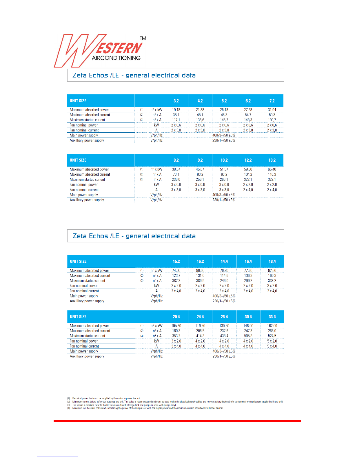
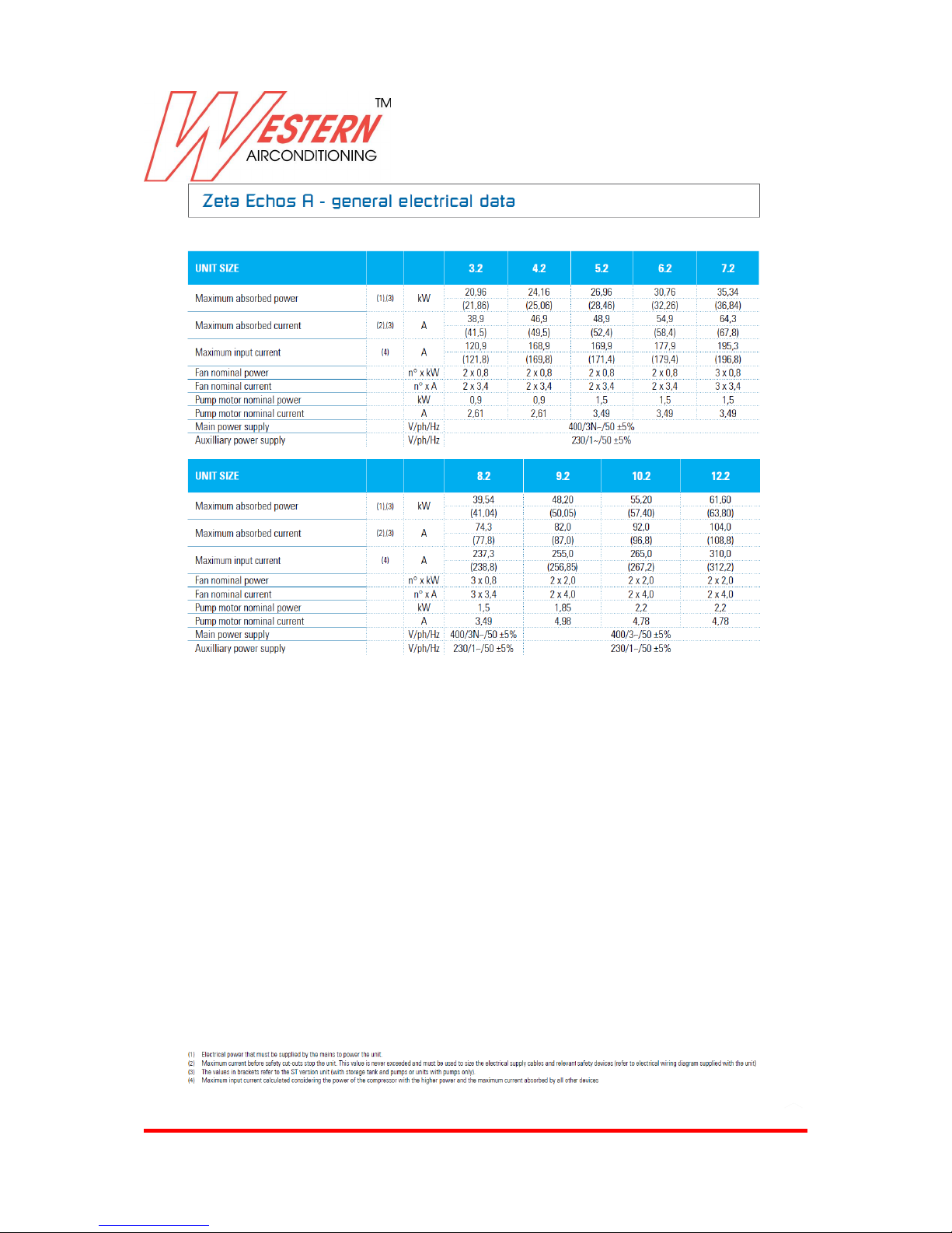
Electrical data 26
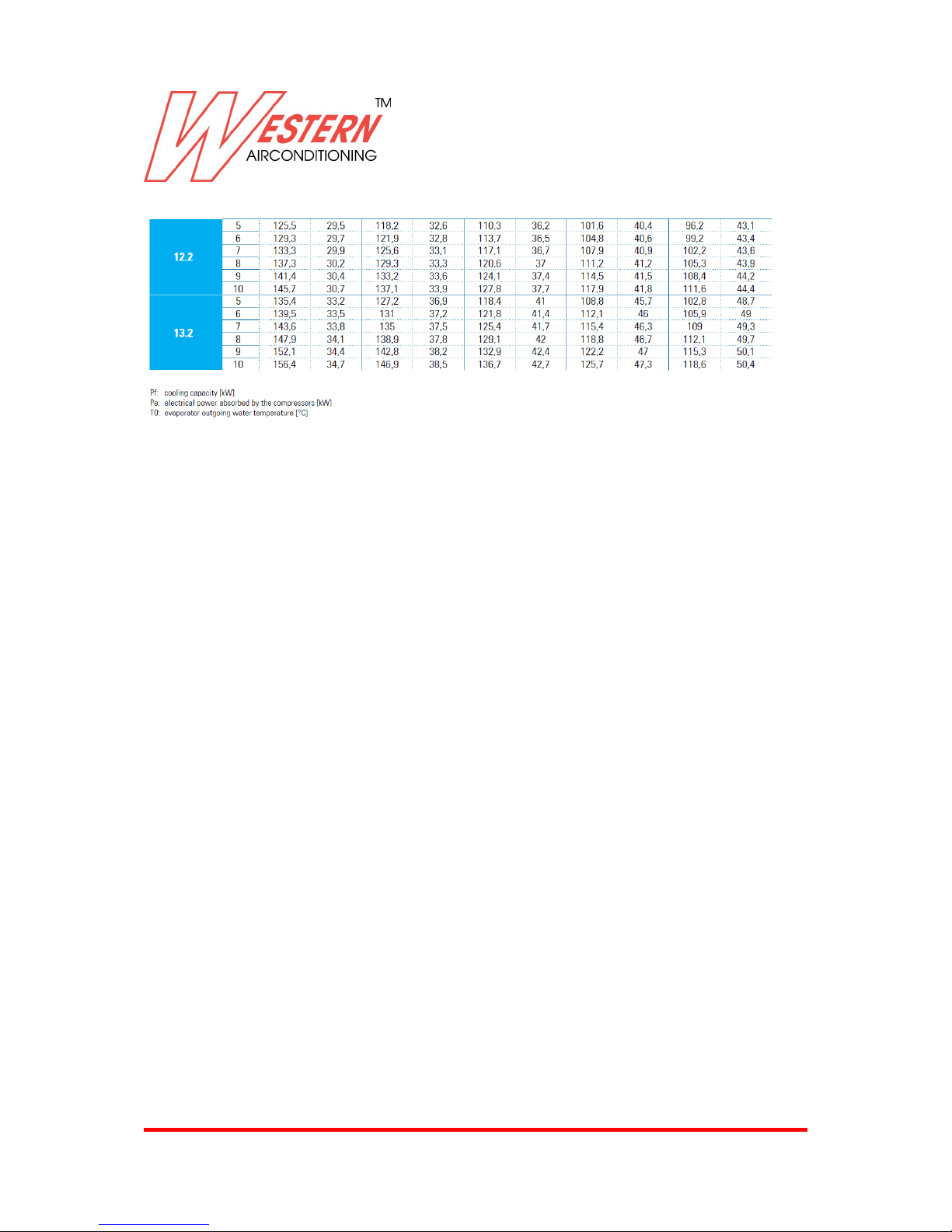
Cooling capacity basic version 30
Heating capacity basic version 32
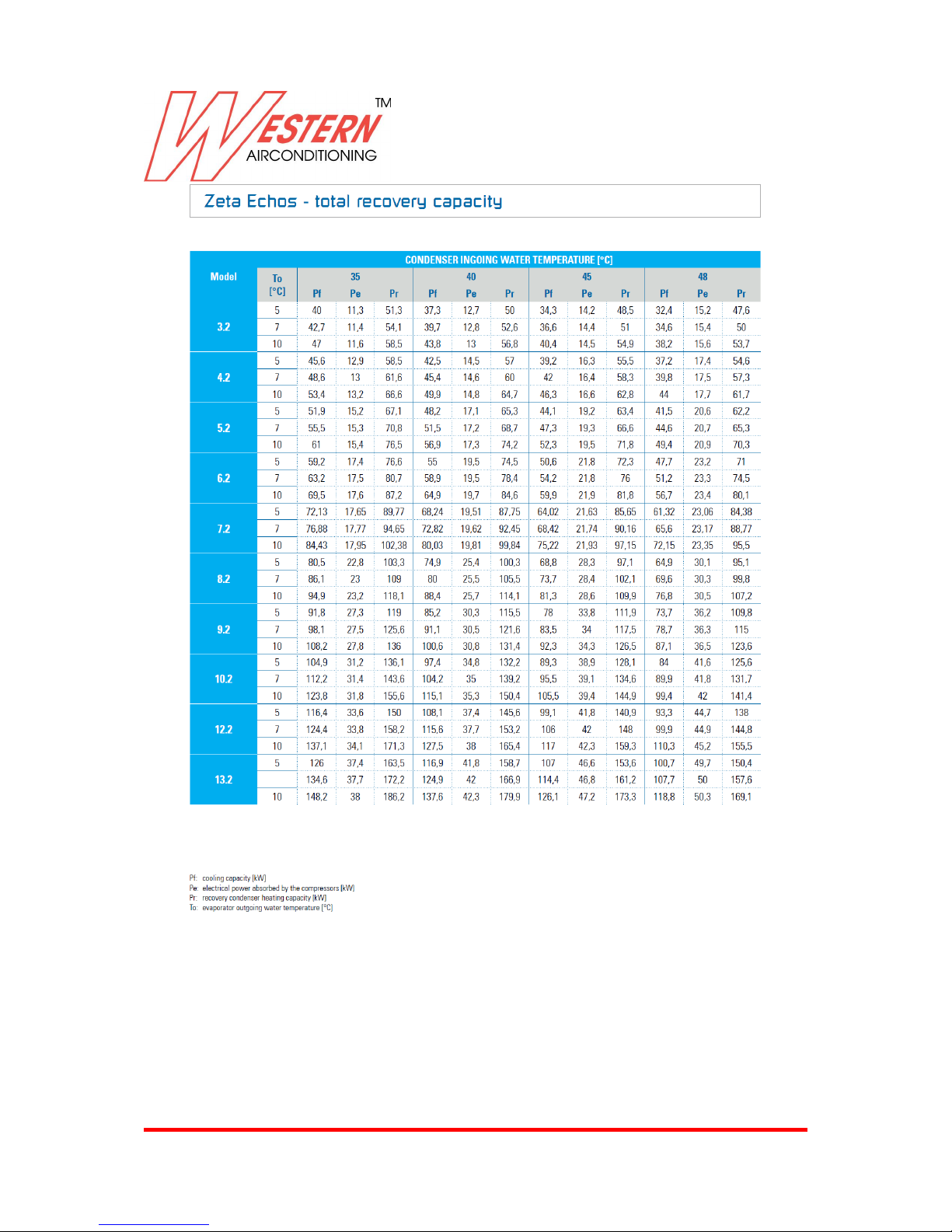
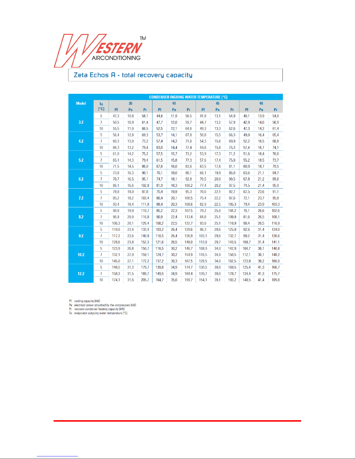
Total recovery capacity basic version 34
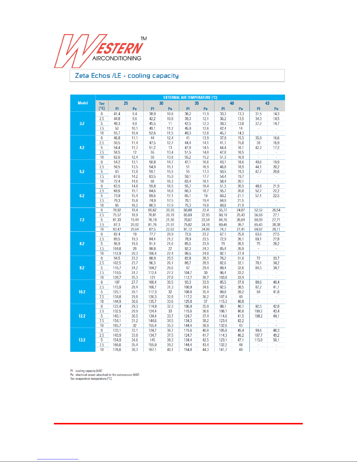
Cooling capacity LE version 35
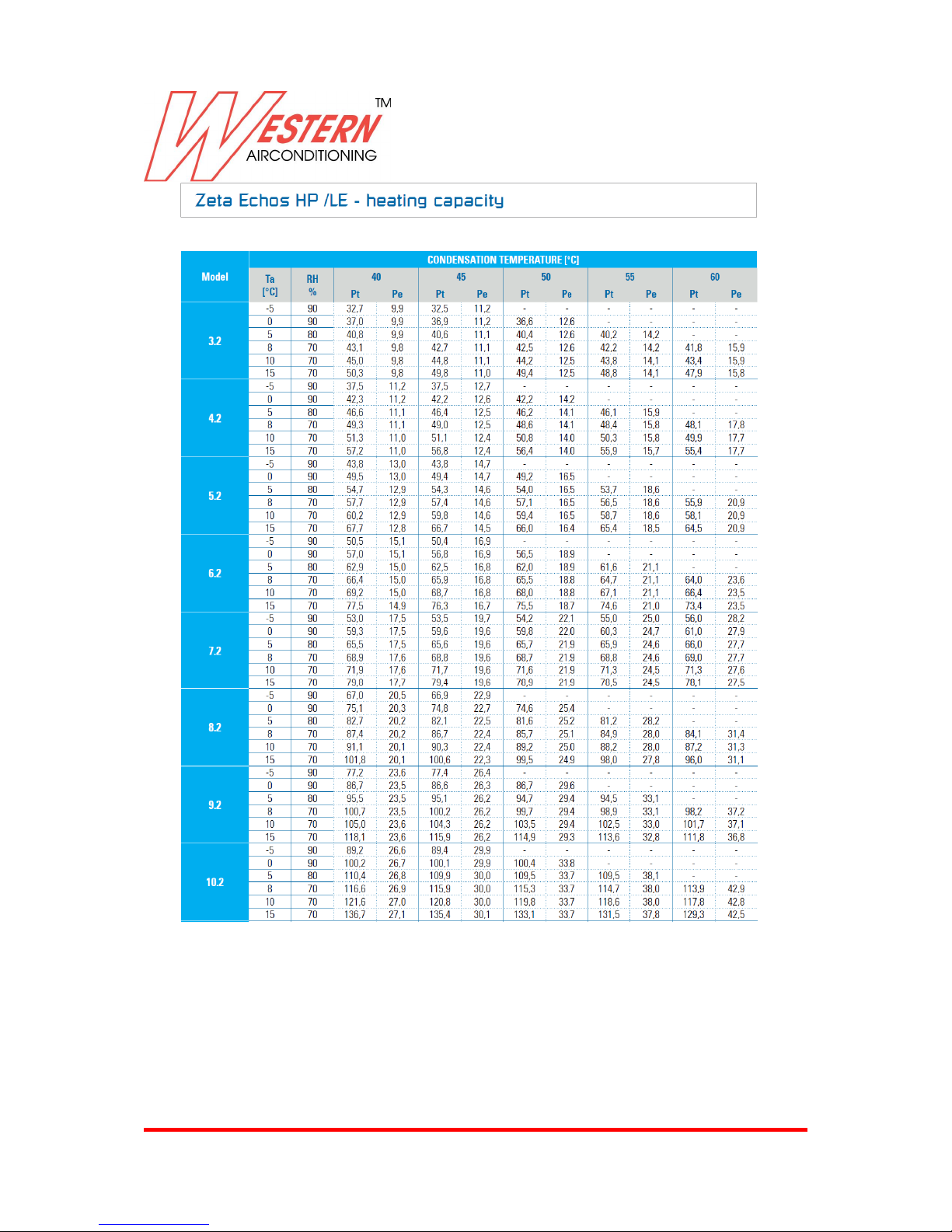
Heating capacity LE version 36
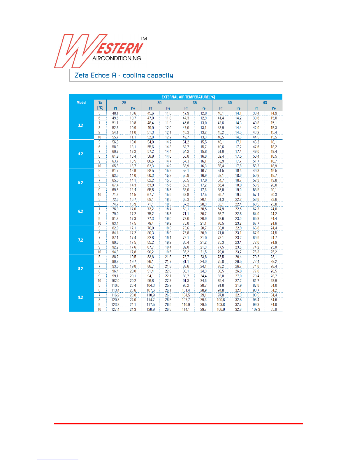
Cooling capacity A version 38
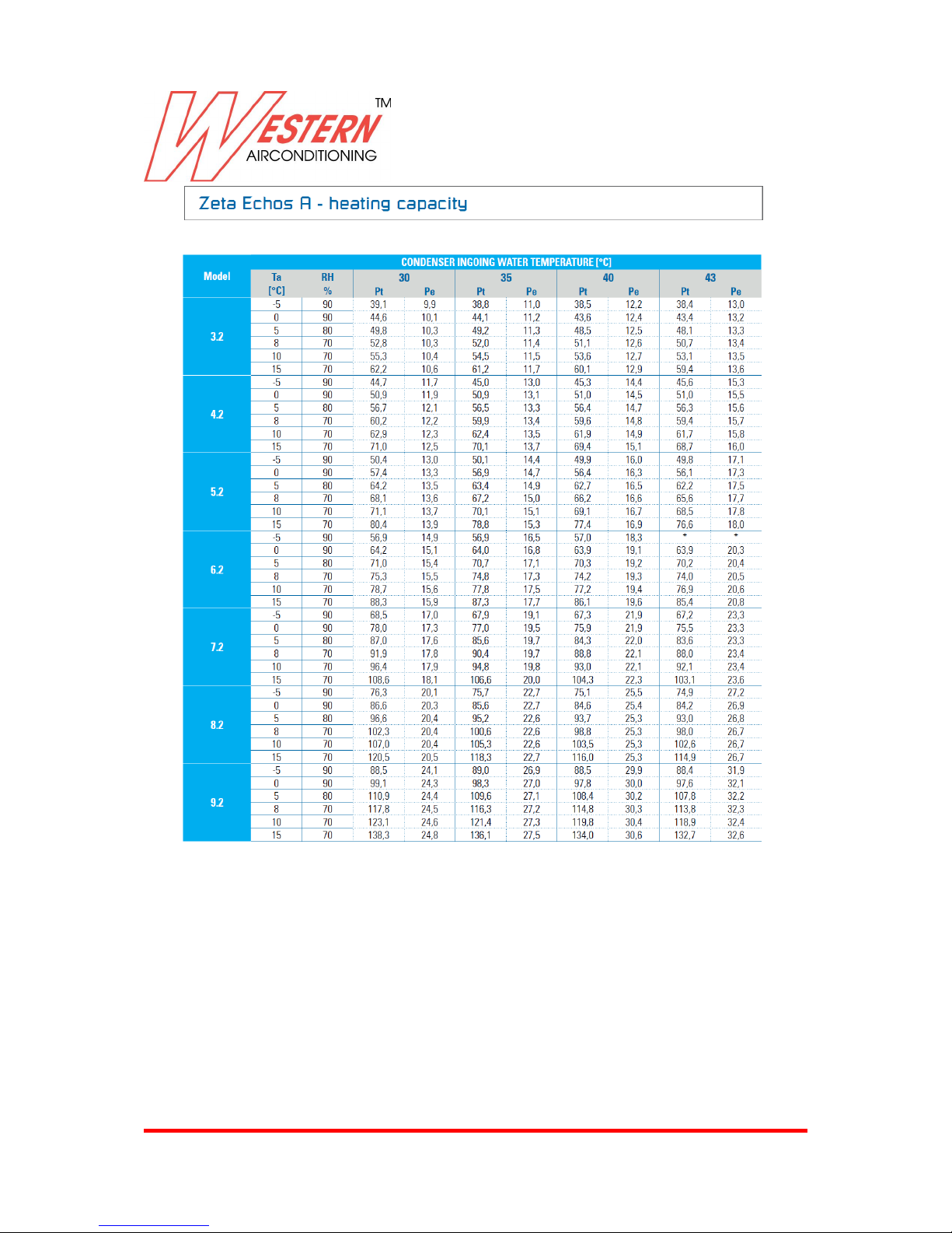
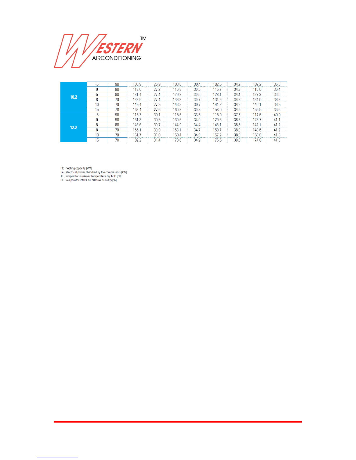
Heating capacity A version 40
Total recovery capacity A version 41
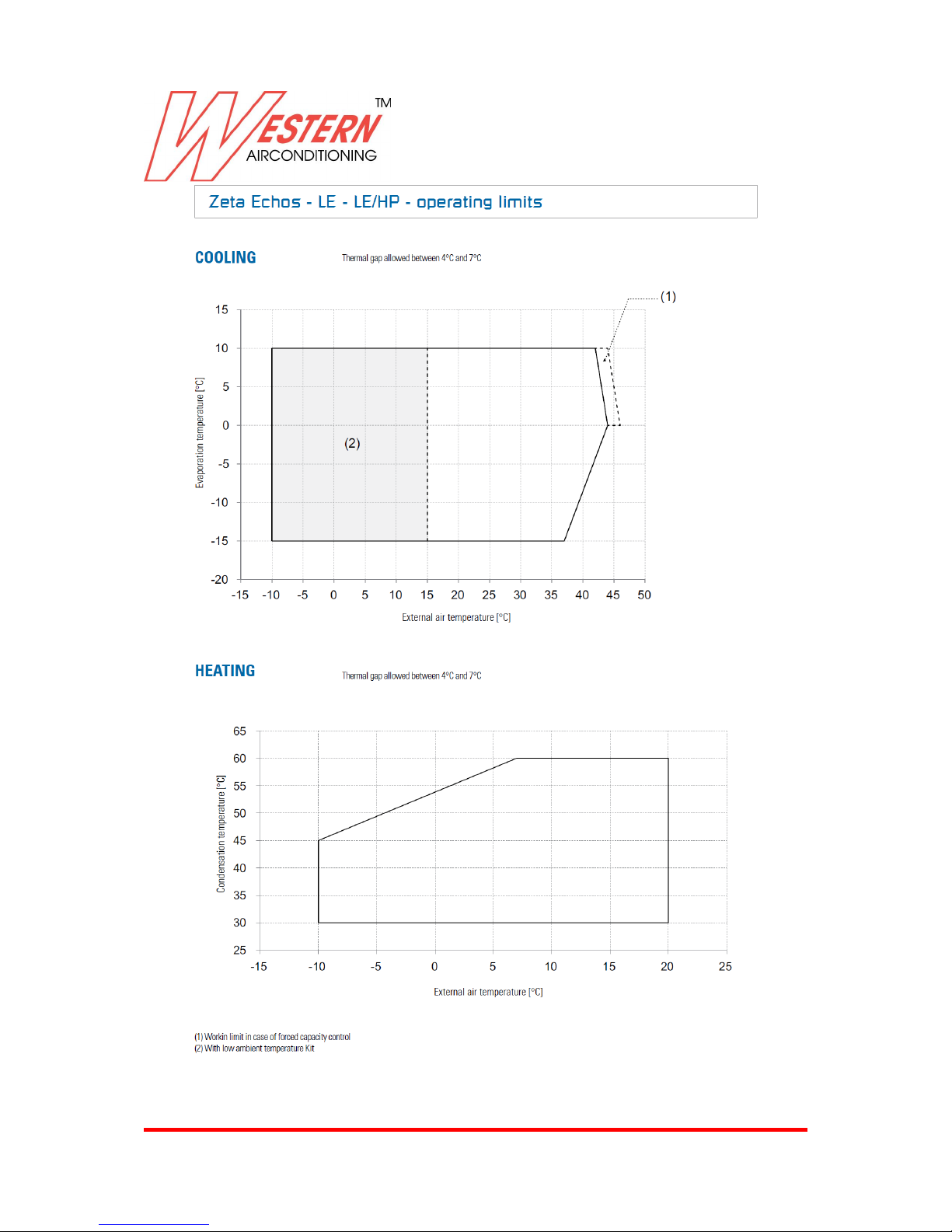
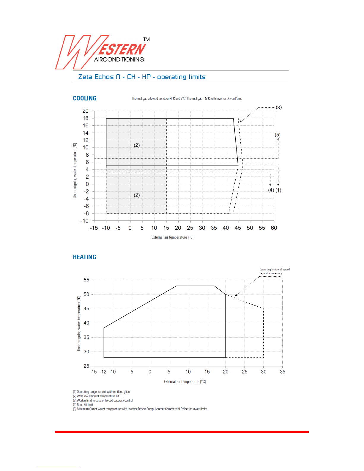
Operating limits 43
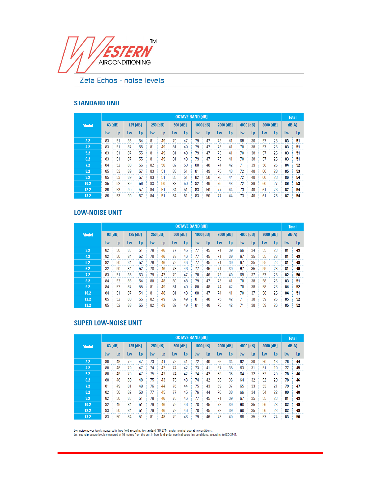
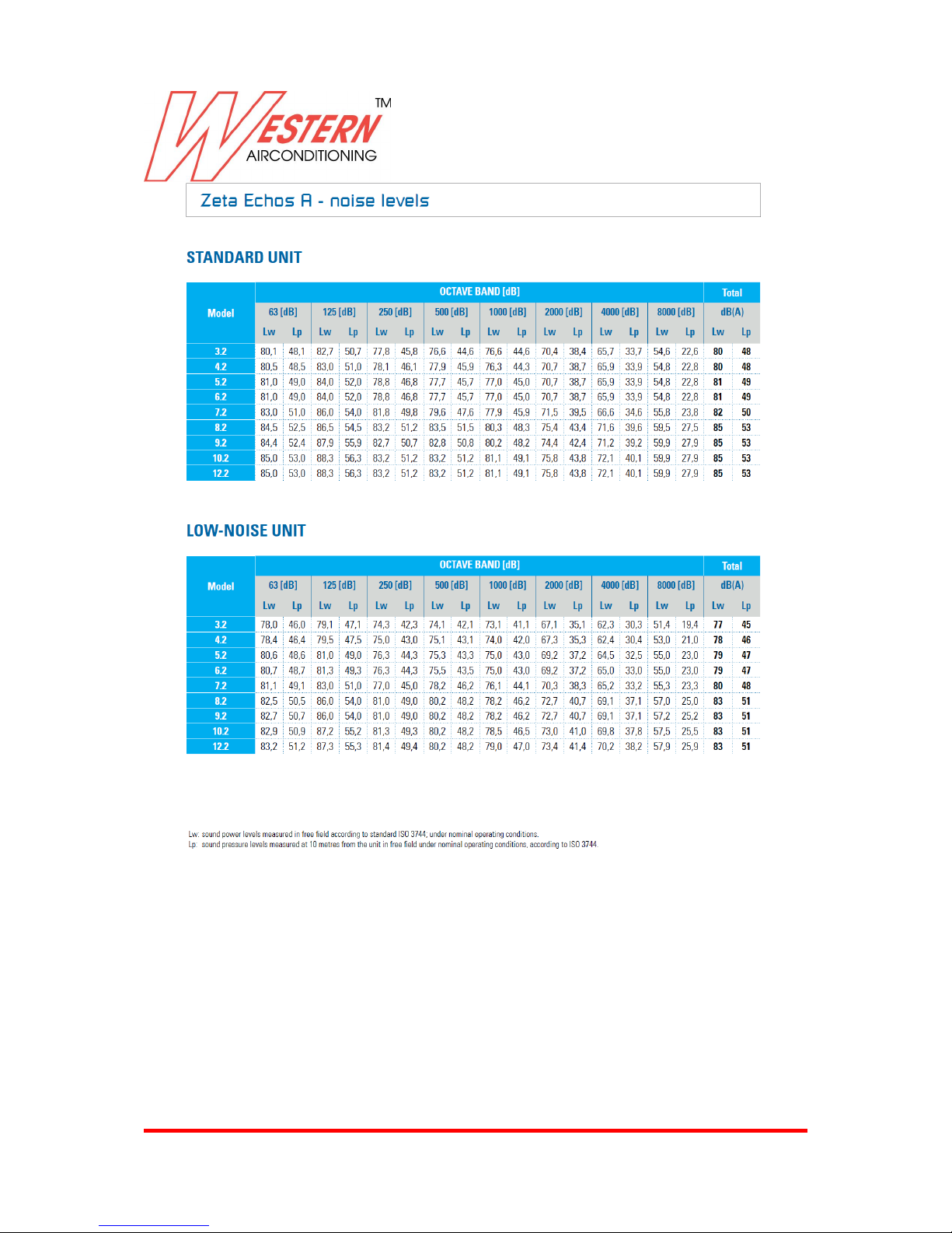
Noise levels 46
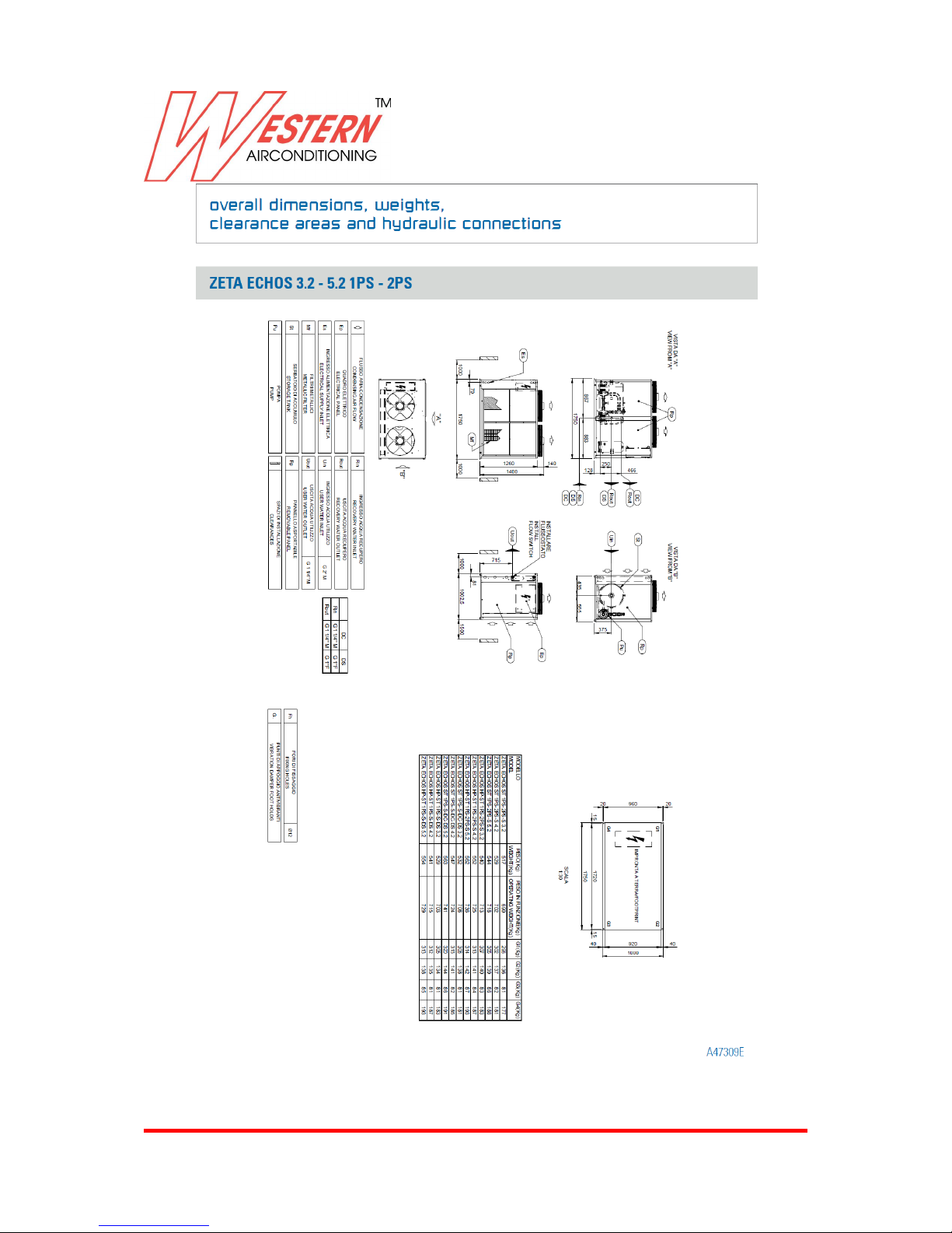
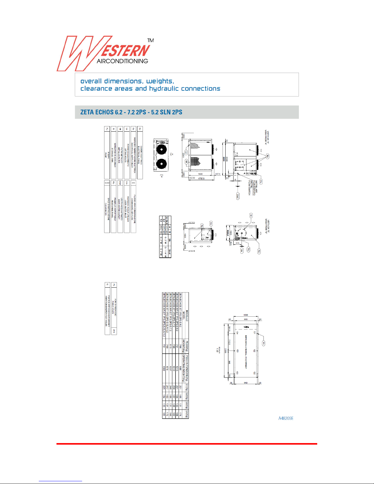
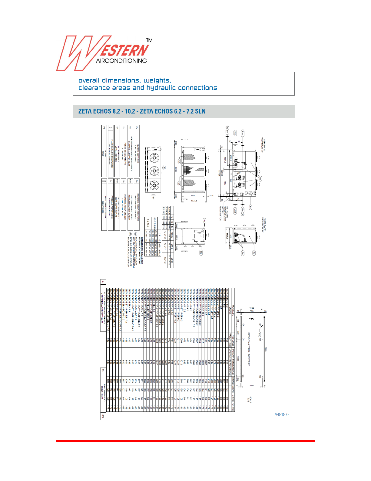
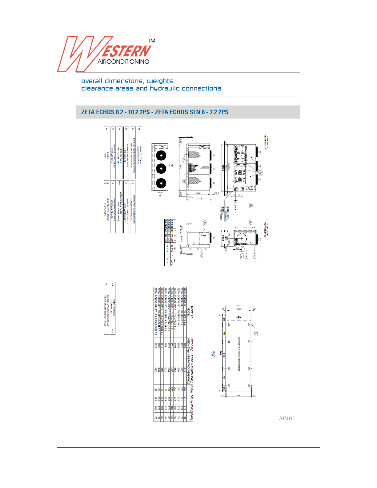
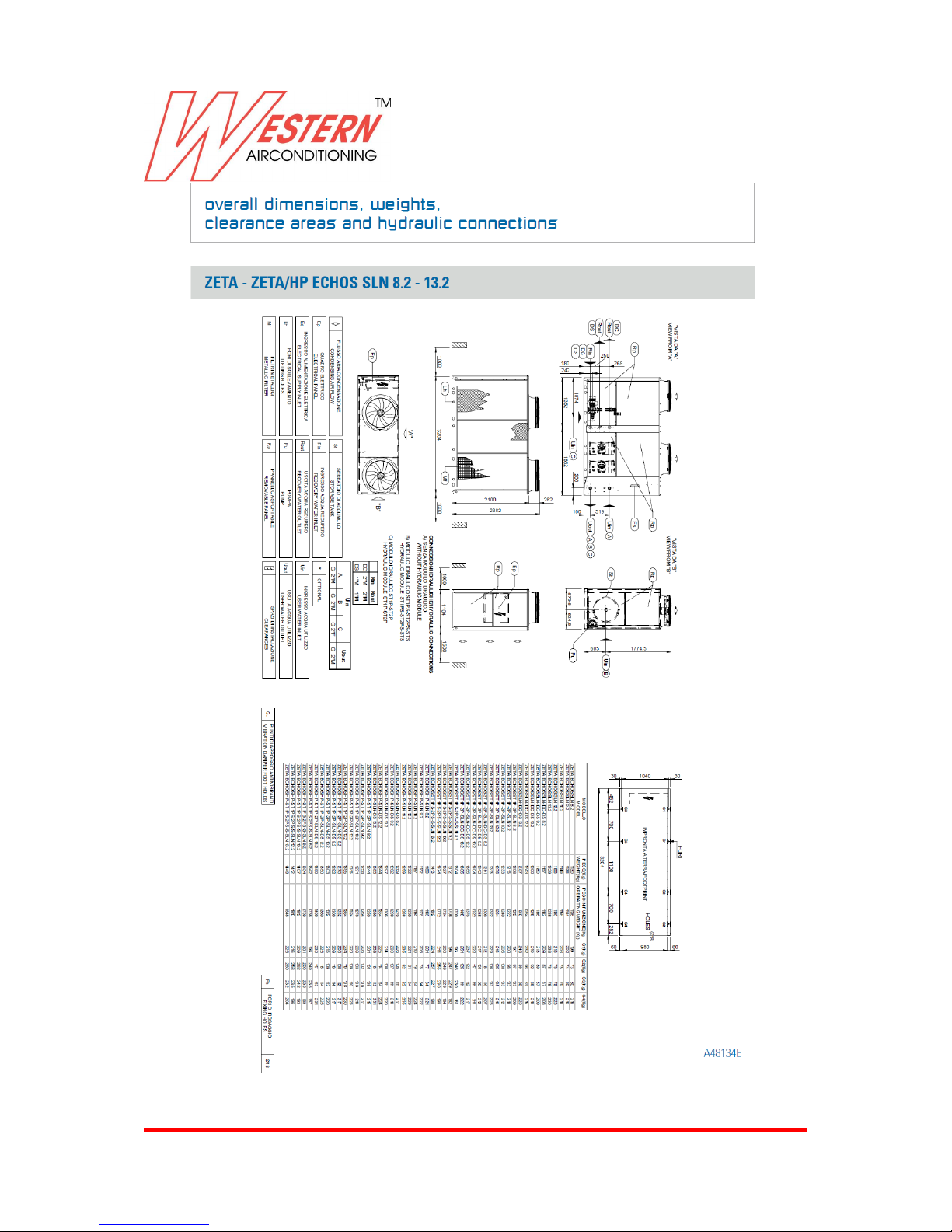
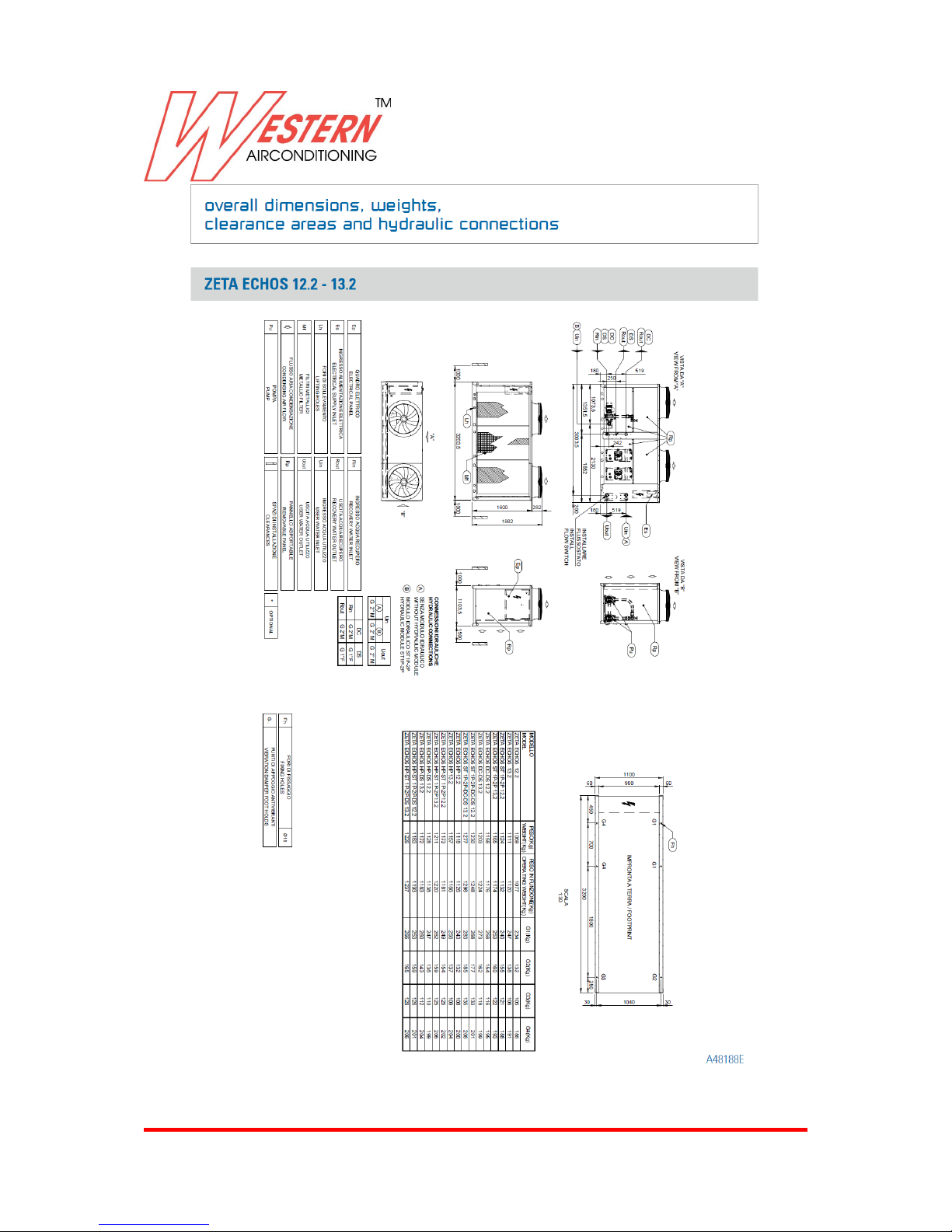
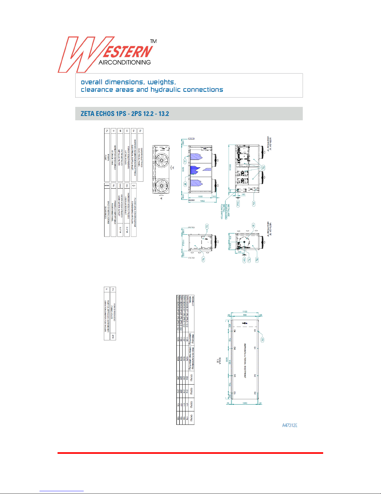
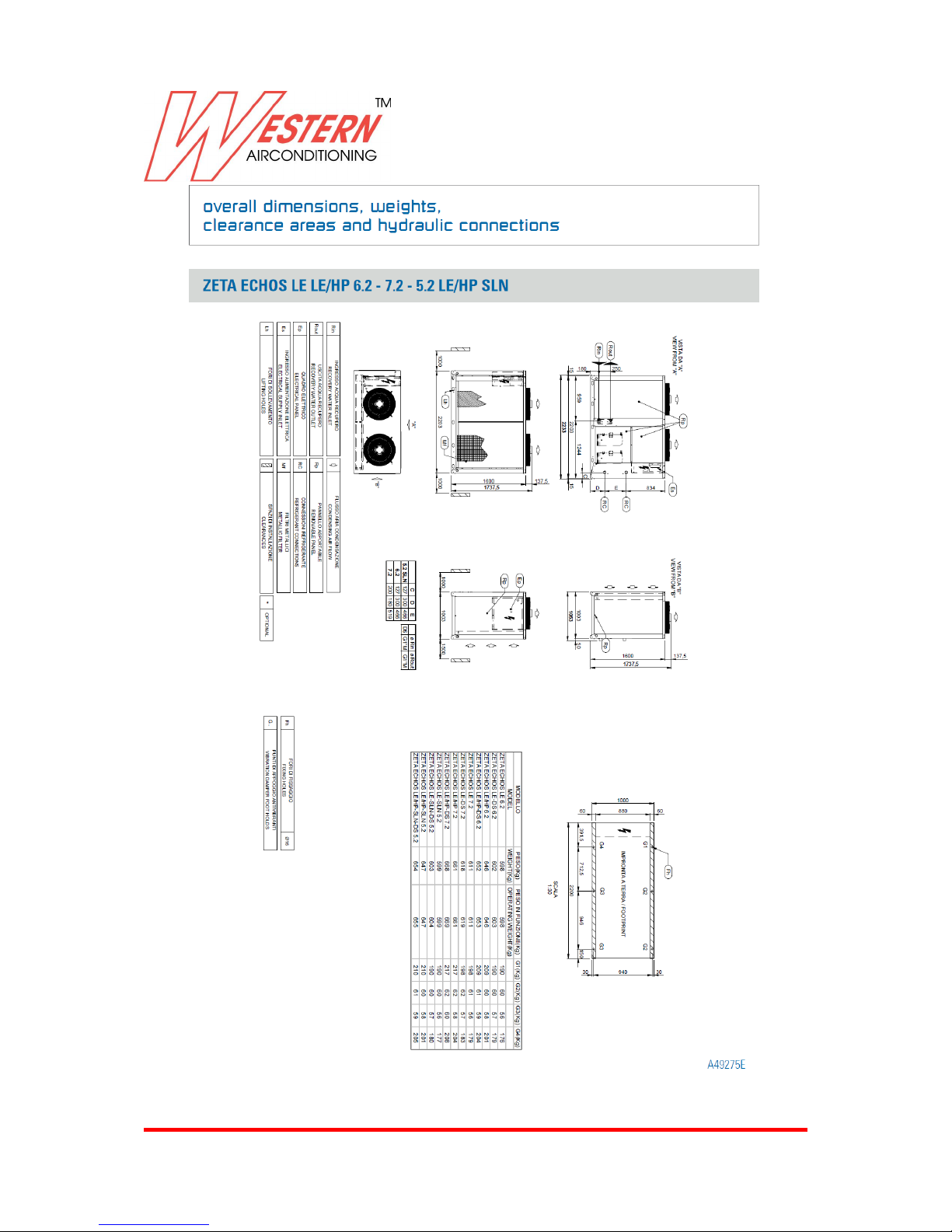
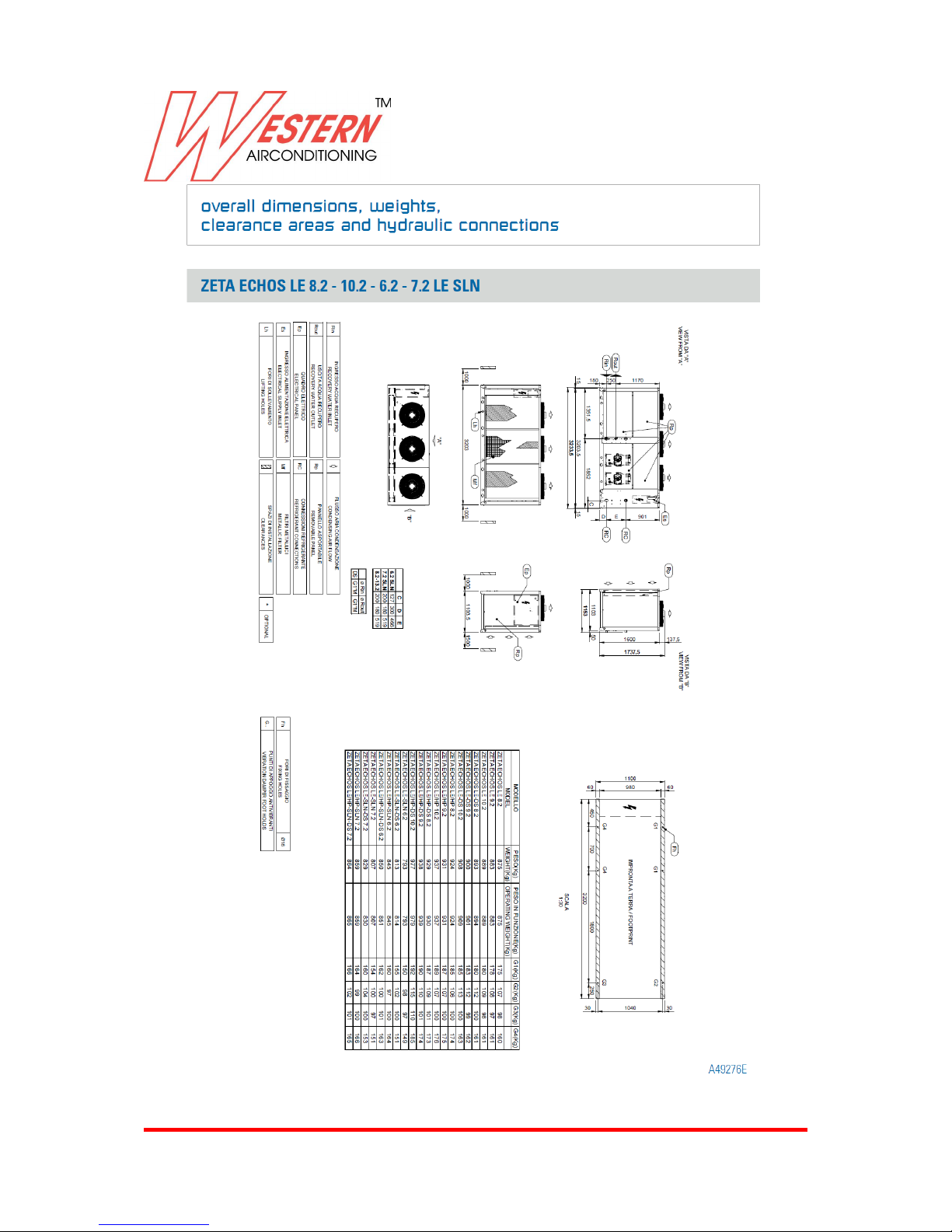
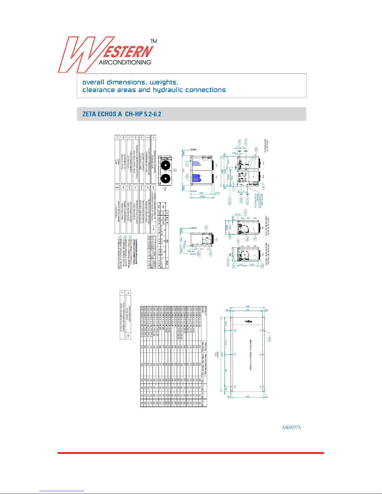
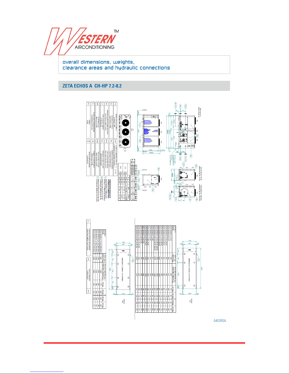
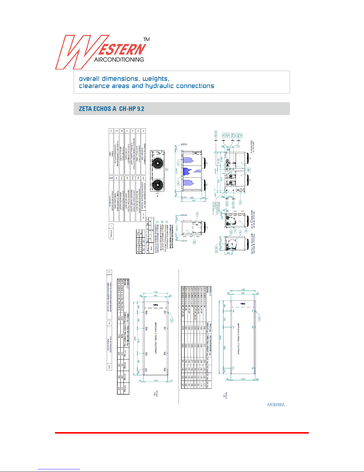
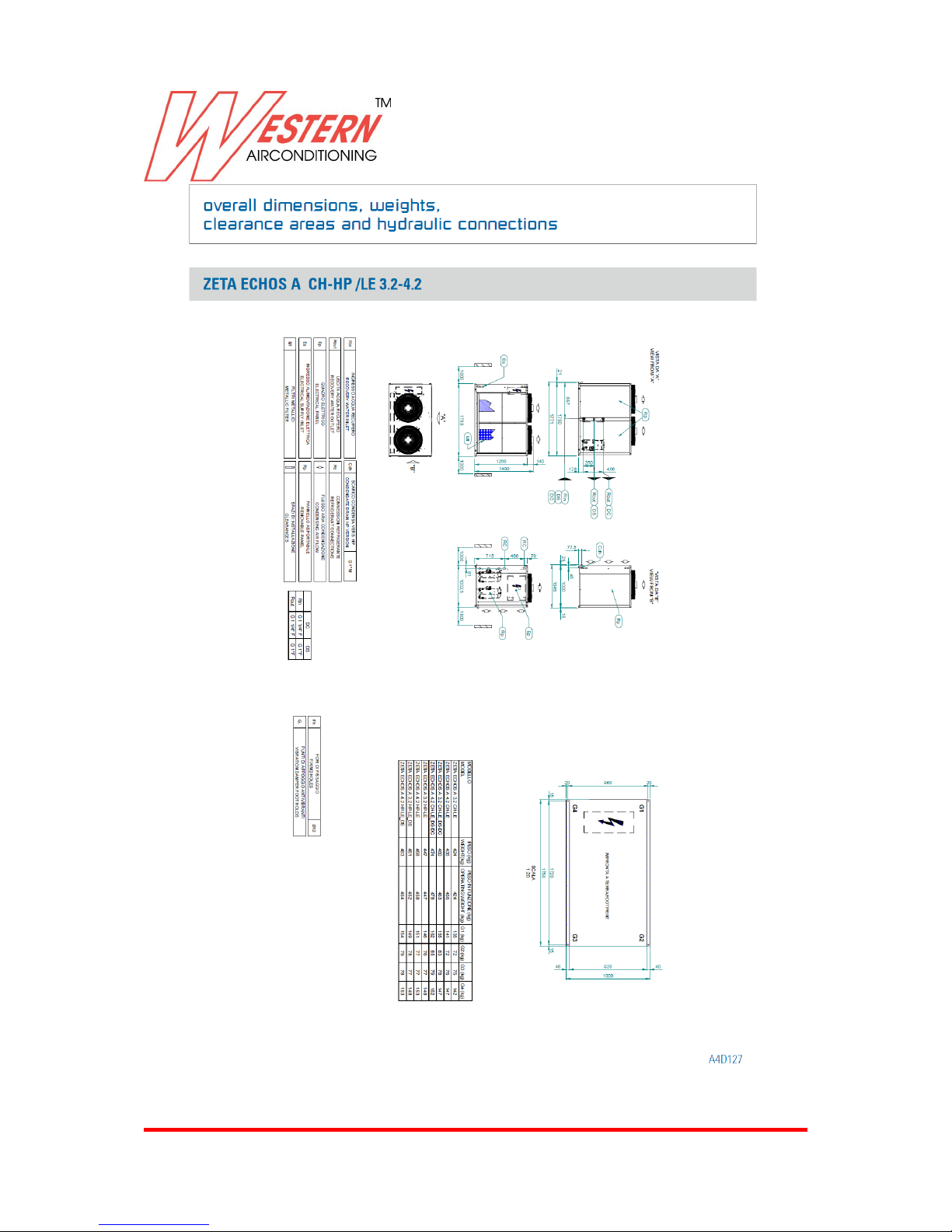
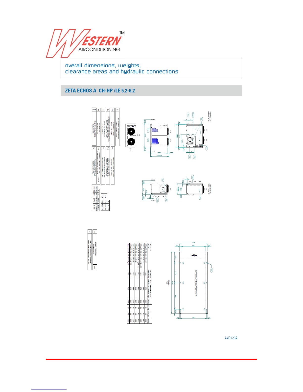
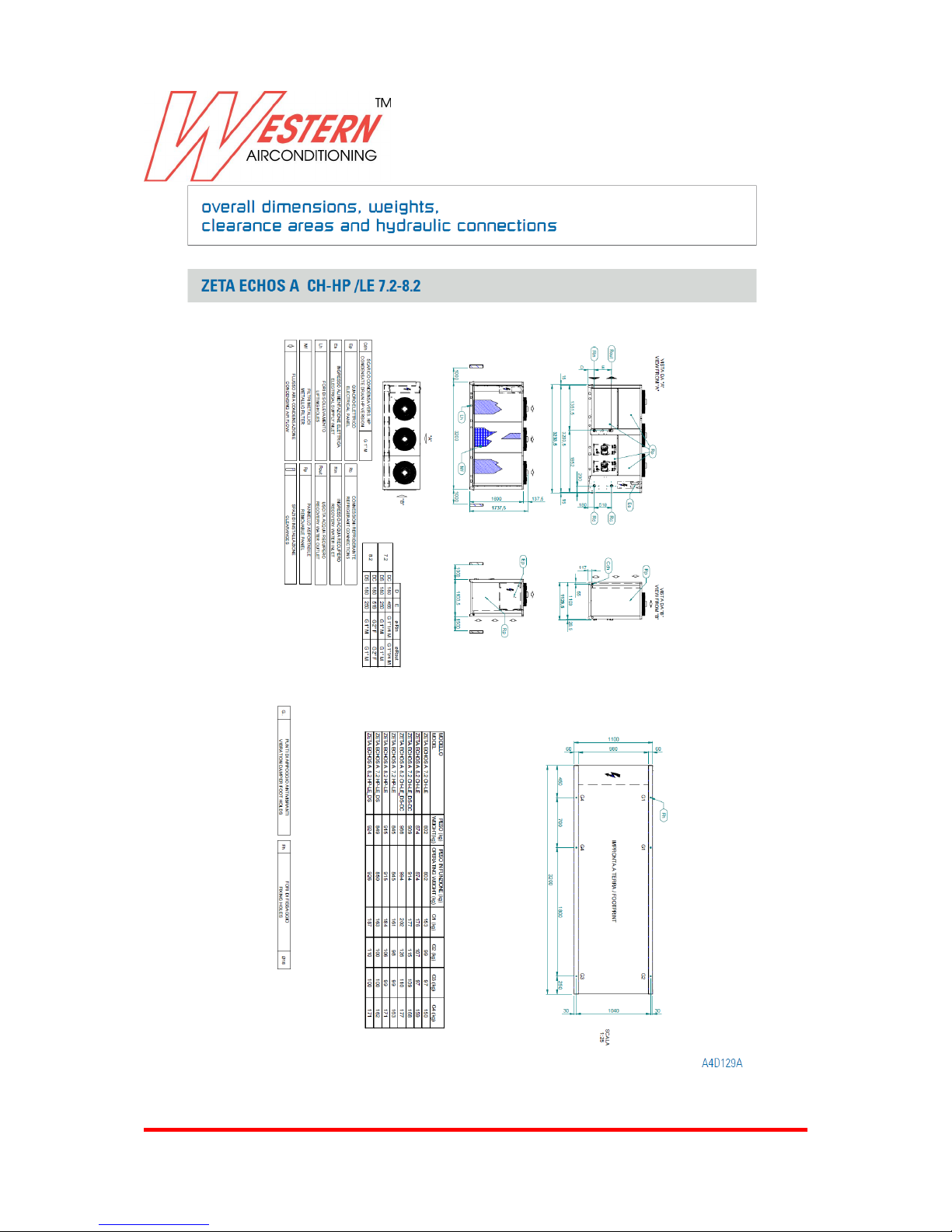
Overall dimensions, weights, clearance
areas and hydraulic connections 48
Installation guidelines 70
Page 4

Western Airconditioning B.V. reserves the right to alter specifications
4
TECHNICAL FEATURES
ZETA ECHOS
Air cooled water chiller with hermetic scroll compressors and brazed plate evaporators. Basic unit
outfit.
STRUCTURE
Self-supporting frame and removable panels lined with noise-absorbent expanded polyurethane
matting in galvanised steel sheet painted in RAL 7035 and the top of the unit in RAL 5017 with
polyester powder at 180°C, to offer high weather resistance. Screws and
bolts in Stainless Steel.
COMPRESSORS
Parallel connected hermetic rotary screw scroll type compressors with oil level gauge, klixon thermal
protection and oil equalization system. Enclosed in an insulated compartment and separated from the
air flow, the compressors are
accessible through the special panels for maintenance operations, even when the unit is on.
CONDENSERS
The heat exchanger is composed of an aluminium-finned copper-tube multirow coil, of high efficiency.
The finned coil pack is protected by a metal mesh.
ELECTRO FANS
Axial fans designed to enhance performance and reduce noise emissions, driven directly by a 6-pole
electric motor with integrated klixon thermal protection. Motor protection degree is IP 54. The fan is
fitted with a protection grille in
compliance with UNI EN 294.
EVAPORATOR
Plate type heat exchanger in AISI 316 stainless steel covered with closed-cell foam.
Each evaporator is equipped with temperature probe for antifreeze protection and vane operated flow
switch supplied as standard. The plate heat exchangers provide for:
• Increased COP/EER;
• Reduced refrigerant charge;
• Reduced volume and weight of the unit;
• Easier maintenance.
COOLING CIRCUIT
Comprises: fluid valve, feeding plug, fluid sight glass, dehydrating filter, thermostatic expansion valve
for pressure external control, high and low pressure switches and safety valve.
Page 5

Western Airconditioning B.V. reserves the right to alter specifications
5
TECHNICAL FEATURES
ELECTRICAL PANEL
The panel consists of:
• Main disconnect switch;
• Fuses for main and auxilliary power circuit protection ;
• Magnetothermic switches, pumps (if present);
• Compressor remote switches;
• Fan remote switches ;
• Pump remote switches (for ST version)
• Microprocessor to control the following functions:
- Control of ingoing water temperature;
- Anti-freeze protection;
- Compressor operation timers;
- Automatic rotation of compressor start-up sequence;
- Alarm signals;
- Alarm reset;
- Capacity steps;
- Cumulative alarm contact for remote signaling;
- Forced capacity reduction according to pressure limits;
• Display of:
- Ingoing and outgoing water temperature;
- Currently set temperature and differential;
- Alarm description;
- Hour counter for compressor operation;
• Black box function;
- Power supply (V/ph/Hz): 400/3~/50 ±5%.
CONTROL AND SAFETY DEVICES
• cooled water temperature control probe (on evaporator intake);
• anti-freeze probe on evaporator outtake;
• manual reset high pressure controller;
• controlled manual reset low pressure switch;
• high pressure safety valve;
• compressor overtemperature protection;
• fan overtemperature protection;
• vane actuated mechanical flow switch (supplied as standard)
TESTING
The units are factory-tested and supplied complete with oil and refrigerant.
Page 6

Western Airconditioning B.V. reserves the right to alter specifications
6
VERSIONS
Check the table with the available configurations for any interferences between one option and the
other.
ZETA ECHOS A:
high performance unit
Zeta Echos Class A carries the hallmark of energy-saving thanks to an EER of the chiller operation
always greater than 3.1! There are 9 sizes available, with a capacity range from 44 to 135 kW,
classified in full compliance with the regulations set by EUROVENT as high energy efficiency class.
The diagram below describes the increase of energy efficiency of the Zeta Echos range, at 100%
charge (EER) and partial charge (ESEER), according to the EUROVENT provisions.
ZETA ECHOS /HP:
reversible heat pump
Beside the basic version components, the unit comprises:
- 4-way reversing valve;
- fluid collector;
- a second thermostatic valve;
- solenoid valve on fluid line from 6.2 at 13.2;
- enablement of summer/winter mode switching and automatic defrosting via microprocessor, with a
patented logic, which ensures optimal activation and duration of defrosting operations.
ZETA ECHOS /LE:
Page 7

Western Airconditioning B.V. reserves the right to alter specifications
7
motocondensing unit
In addition to the basic version, this unit has no evaporator and thermostatic valve fitted.. The fluid
receptors can be supplied as accessories. The solenoid valve on the fluid line is supplied as standard.
The unit is supplied without refrigerant charge.
ZETA ECHOS /LE /HP:
heat pump motocondensing unit
In addition to the basic version ZETA ECHOS/HP, this unit has no evaporator and thermostatic valves
fitted. The solenoid valve on the fluid line is supplied as standard. The unit is supplied without
refrigerant charge.
Page 8

Western Airconditioning B.V. reserves the right to alter specifications
8
HYDRAULIC SYSTEM OPTIONS
ZETA ECHOS /ST 2PS
unit with pumps and tank
Beside the basic version components, the unit comprises:
- insulated storage tank;
- two circulation pumps of which one in stand-by mode, with automatic switch in case of failure;
- expansion vessel;
- check valve:
- gate valves.
The ST version is available in four additional configurations:
- ST 1PS: unit with pump and tank;
- ST 1P: unit with single pump without tank;
- ST 2P: with 2 pumps without tanks;
- ST S: with tank without pumps.
ACCESSORY VERSIONS
ZETA ECHOS /DC
unit with recovery condenser
Beside the basic version components, the unit comprises a recovery condenser on each cooling circuit
(recoverying 100% of the condensing heat for the production of hot water) and a fluid receptor. The
condenser is brazed plate type. The accessory is available for sizes from 3.2-13.2 "1p-2p" and for all
models without hydraulic module; is not available for the HP models. The control automaticaly enables
the recovery function, depending on water temperature, and controls its safety desablement in case of
high pressure. For maximum benefit use the accessory combined with the circuit regulator. The
accessory is available for all models. It is not available for the HP version.
ZETA ECHOS /DS
unit with desuperheater
Beside the basic version components, the unit comprises a brazed plate recovery condenser on each
cooling circuit
(recoverying 20 % of the condensate, connected in series with the condenser coil). The accessory is
available for models from 3.2 to 13.2 with "1P-2P" and for all models without hydraulic module. For
maximum benefit use the accessory combined with the circuit regulator. This version is also available
for HP outfit. In this case, the system must be equipped with a shut-off valve on the water recovery line
during the HP mode operation, as shown in the manual.
ZETA ECHOS /LN
low-noise unit
In addition to the basic version components, this unit has a fully soundproofed compressor
compartment (using high acoustic impedance and sound-absorbent materials).
ZETA ECHOS /SLN
super low-noise unit
beside the /LN version components, the coil surface is larger, fans have reduced speed and a turn
regulator.
Page 9

Western Airconditioning B.V. reserves the right to alter specifications
9
ACCESSORIES
REFRIGERANT CIRCUIT ACCESSORIES
- Electronic thermostatic valve;
- Condensing pressure controlled by operation circuit regulator with low external temperatures;
- Double set point (high/low temperature) with a single electronic expansion valve. The evaporator is
sized according to high temperature operation. The set point can be changed from the keyboard or
the digital input, in this case must be specified in the order;
- High and low pressure switches are available for all models;
- Fluid receptors (supplied as standard for HP, HP/LE and DC, DC/LE versions);
- Intake and delivery valves on compressor line;
- Solenoid valve on fluid line (supplied as standard for HP and HP/LE and LE versions);
- Low water temperature kit.
HYDRAULIC CIRCUIT ACCESSORIES
- Defroster for the evaporator (the ST version is equipped with an antifreeze resistance on the tank,
piping system and on the pump spiral, which is insulated for this reason) and on any recovery heat
exchanger;
- Water side safety valve (ST version only). The valve calibration value is 6 bar, which corresponds to
the maximum allowed operating pressure.
ELECTRICAL ACCESSORIES
- Serial interface RS485 suited for Carel and Modbus protocols;
- Power factor correction cos ⱷ ≥ 0.9 under nominal operating conditions; on the external board in IP
55 (power supply connected by the installer directly on the main). The accessory is combined with
dry contacts;
- Remote user terminal (in addition to the standard one);
- Dry contacts.
MISCELLANEOUS ACCESSORIES
- Rubber antivibration mounts;
- Copper/copper condensation coil;
- Copper/tinned-copper condensation coil;
- Prepainted aluminium condensation coil;
- Condensation coil with passivated aluminium and polyurethane coating.
The treatment consists of a double layer, the first of which passivates the aluminium and acts as a
primer and the second which is a polyurethane-based surface coating. The product has high anticorrosive properties and virtually resists to all environmental conditions. For installation in marine
and rural environments, from industrial to urban areas;
- Packaging in wooden crates;
- Special pallet/skid for container shipment;
- Non-standard “RAL” paint colours.
DOUBLE SET-POINT
The microprocessor enables you to set two set temperatures for the production of cold and hot water.
Unless specified otherwise in the order, the default values are 12/7°C and 15/10°C for chiller mode
and 40/45°C and 35/40°C for heat pump mode. The set temperatures must, in any case, remain within
the operating ranges of the unit.
Use either the keypad or the digital input to switch between the first and second set. For series that do
not permit the simultaneous selection of “Select summer/winter mode with digital input” and “Double
set point with digital input”, summer/winter mode can be selected only on the keypad while the double
set point still uses the digital input, as per our standard.
Page 10

Western Airconditioning B.V. reserves the right to alter specifications
10
EC FANS
Units can be couples to the innovative direct current EC axial fans with electronically commutated
brushless motor.
Theses motors with permanent magnets rotor ensure a high level of efficiency for all work conditions
and allow to obtain a 15% saving per fan.
Moreover, through a 0-10V analogical signal sent to every fan, the microprocessor allows to control
the condensation through continuous air flow regulations on variation of the outdoor air temperature
and the consequent sound emission reduction.
“BRINE KIT”ACCESSORY
It is applied if the evaporator output temperature is included within +3°C and
-8°C. It consists in a higher thermal insulation of the exchanger and piping, a specific calibration of the
low pressure switches and of the anti-freeze alarm, and dimensioning check of the mechanical
thermostatic valve.
If it is not included in the set-up, the “Check condensation” accessory must be added.
ELECTRONIC THERMOSTATIC VALVE
The use of this accessory is particularly indicated for units that operate in very unstable heat load
conditions or in unstable functional mode, as in the case of joint management of air conditioning and
production of high temperature water. Use of the electronic thermostatic valve in fact allows to:
Maximize the heat exchange to the evaporator
Minimize response times on load variation and on operative conditions
Optimize the regulation of the over-heating
Guarantee maximum energy efficiency
SELF-ADAPTABLE REGULATION LOGIC
This function allows the unit control the dynamically vary the outlet waters set point according to the
stop and functional cycles of the machine: in practice, by increasing an reducing the water outlet
temperature, the control avoids that compressor start-ups are too close in time, decreasing the
number of peaks and protecting the unit components.
SOFT-STARTER
Blue Box units adopt all the required functioning set-ups and logics to minimise peak currents. The
Soft-Starter accessory allows a further 40% reduction of normal current peaks, through an electronic
control of the electric motor start-up.
COMPENSATION OF THE SET-POINT to the external air temperature
The unit microprocessor control can compensate the set point in an dynamic way, on variation of the
external air temperature. The compensation can be positive or negative: with positive compensation,
on increase of the air temperature the functioning set also increases. With negative compensation on
increase of the air temperature the set decreases. Compensation can be made either on the summer
set point or on the winter set point (heat pumps).
By default, both summer an d winter negative compensation is set, but this configuration can be
modified from the microprocessor keyboard. Unless otherwise specified, default values are indicated
in the graphics below.
Page 11

Western Airconditioning B.V. reserves the right to alter specifications
11
Page 12
Western Airconditioning B.V. reserves the right to alter specifications
12
INVERTER DRIVEN PUMP (PER ST1P/S 0 ST2P/S)
Energy savings:
Variable flow pumps have become more widespread over the years to optimise air conditioning and
cooling systems. Thanks to the inverter Driven Pump, Western Airconditioning offers an alternative
method that differs from conventional layouts: a constant flow primary pump and a variable flow
secondary pump.
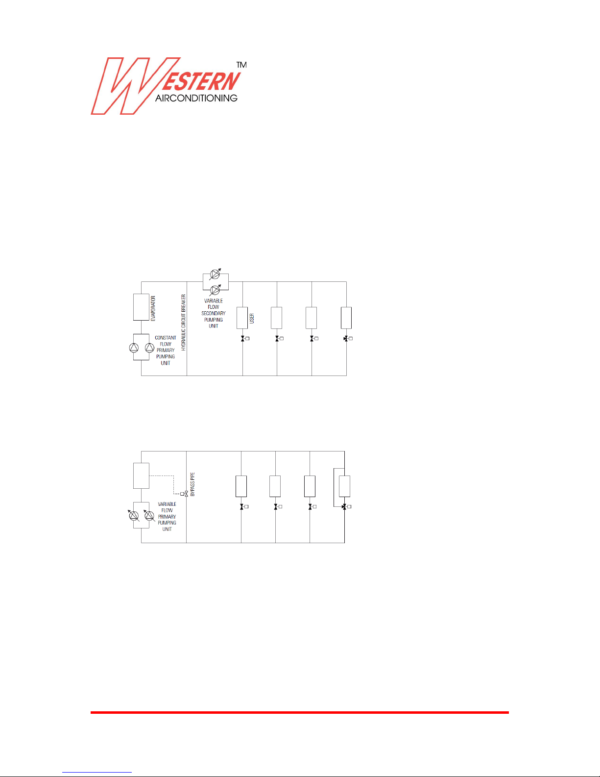
Let’s compare the two solutions:
1) The figure below shows the layout of a constant flow primary pump and a variable flow secondary
pump. Please note the use of the decoupling pipe between the primary and secondary system
(design to cover the entire flow rate): if the utilities only require a percentage of the nominal power,
the decoupling pipe recirculates the excess flow, which means wasting pumping energy.
The figure below shows a system with only variable flow primary, which also serve the secondary
system. The bypass pipe and the two-way control valve ensure minimum water flow through the
evaporator when the request is below the allowed minimum water flow rate than the nominal one. This
allows to considerably reduce energy losses related to the mixing process, which in traditional systems
are caused by the hydraulic circuit breaker.
Benefits of the Inverter Driven pump:
Saving a set of pumps
Reduced overall dimensions of the machines’ housings
Lower piping costs
Reduced pressure drops
Greater energy efficiency on the pump side
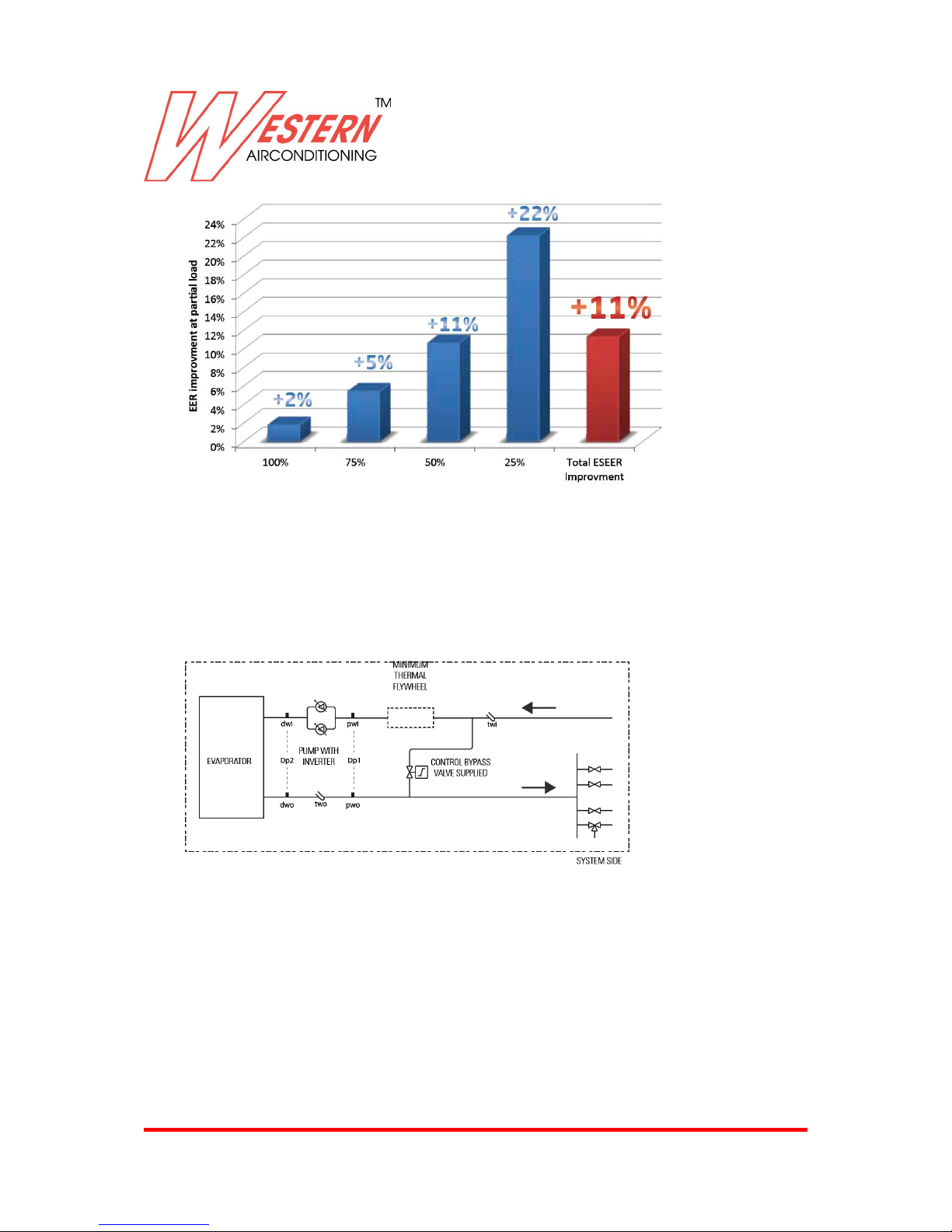
As we can see from the graph under EUROVENT conditions, the systems in the diagrams have higher
efficiency under part-load conditions, considering the energy consumed by the pumps as well as by
the chiller (compressors plus fans)
Page 13
Western Airconditioning B.V. reserves the right to alter specifications
13
Energy savings in these conditions can be as high as 11% per year and sometimes even more!
Inverter Driven Pump operating logic:
Dp1: System side pressure drops
Dp2: Evaporator pressure drops
When all the utilities are in operation, the unit’s pump runs at the nominal flow rate and with an
available head on the system side equal to Dp1 and evaporator pressure drops equal to Dp2.
The system’s heat load drop causes the shut-off valves of the utilities to close, which results in an
increase in the pressure drops that the pump needs to overcome. At the same time, the inverter’s
control logic will reduce the flow rate, which will determine lower evaporator pressure drops and bring
back the available head to the nominal Dp1 value.
Page 14
Western Airconditioning B.V. reserves the right to alter specifications
14
Key points for a variable flow primary system:
In order for the components of the system to operate optimally, it is important to take some key points
into account:
1) minimum water flow and bypass valve supplied:
The inverter Driven pump also includes the two-way bypass valve supplied with it and adequately
designed in relation to the size of the unit.
If on the system side the heat load is very low, this means that many utilities are closed, which results
in an increase in pressure drops. The inverter counters the Dp1 variation detected by the sensor by
reducing the speed of the pump and the flow rate as a result. However, there is a limit lower than the
flow rate value below which the heat exchange towards the evaporator is not performed properly and
the temperature drop processed by the evaporator increases, which might activate the anti-freeze
alarm. The two-way control valve adequately selected based on the machine model prevents this
alarm from being triggered, thereby ensuring the minimum water flow rate towards the evaporator.
2)”Minimum thermal flywheel”:
In the event of a heat load close to zero, with the unit in maximum power partialisation conditions, the
pump set at the minimum flow rate and closed system valves, the machine might stop due to the antifreeze alarm.
To prevent this problem, there must be a “minimum thermal flywheel” in the evaporator / bypass valve
section.
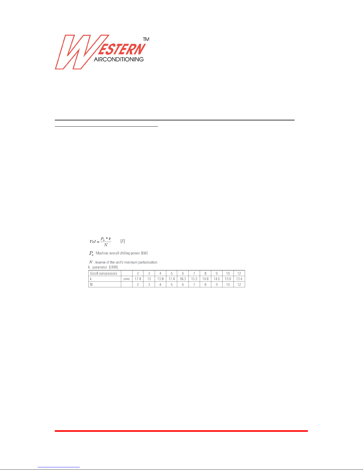
Below is the formula to determine it:
The water content of the evaporator, of the hydraulic module’s inertial tank (if there is one) and of the
pipes between the bypass and the evaporator itself may contribute to determine the “minimum thermal
flywheel”.
However, it is advisable to use three-way valves on a certain number of utilities on the system to
ensure a minimum flow of water towards the system in any condition.
Please note: if this accessory is installed, the minimum cold water temperature at the outlet cannot
drop below 7°C. Moreover, the temperature variation considered under the conditions specified in the
project must be 5°C. Please contact our sale department for the minimum water temperature at the
outlet (production of cold water) and for different temperature drop values.
You should also contact the sales department in the event of production of hot water for temperatures
at the outlet below 40°C.
Attention: the “minimum thermal flywheel” must be between the bypass valve and the evaporator. This
is a part of the “minimum water content of the system” described in the relative chapter; the difference
between the “minimum water content of the system” and the “minimum thermal flywheel” can instead
be positioned in any area of the system.
Page 15
Western Airconditioning B.V. reserves the right to alter specifications
15
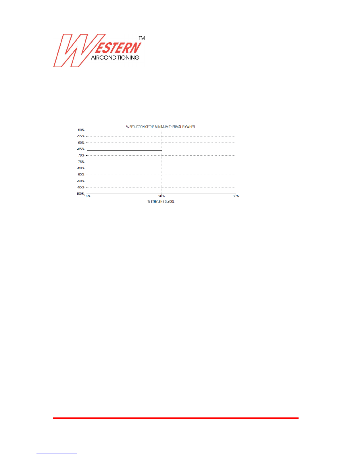
The “minimum thermal flywheel” allows the unit to operate correctly also in heat pump mode.
For cooling-only machines, if using ethylene glycol mixes, it is possible to reduce the “minimum
thermal flywheel” based on the curves below.
For scroll compressors:
If the unit is in heat pump mode, the “minimum thermal flywheel” is not reduced even if there is glycol.
Page 16
Western Airconditioning B.V. reserves the right to alter specifications
16
Page 17
Western Airconditioning B.V. reserves the right to alter specifications
17
Page 18
Western Airconditioning B.V. reserves the right to alter specifications
18
Page 19
Western Airconditioning B.V. reserves the right to alter specifications
19
Page 20
Western Airconditioning B.V. reserves the right to alter specifications
20
Page 21
Western Airconditioning B.V. reserves the right to alter specifications
21
Page 22
Western Airconditioning B.V. reserves the right to alter specifications
22
Page 23
Western Airconditioning B.V. reserves the right to alter specifications
23
Page 24
Western Airconditioning B.V. reserves the right to alter specifications
24
Page 25

Western Airconditioning B.V. reserves the right to alter specifications
25
Page 26
Western Airconditioning B.V. reserves the right to alter specifications
26
Page 27
Western Airconditioning B.V. reserves the right to alter specifications
27
Page 28
Western Airconditioning B.V. reserves the right to alter specifications
28
Page 29
Western Airconditioning B.V. reserves the right to alter specifications
29
Page 30

Western Airconditioning B.V. reserves the right to alter specifications
30
Page 31
Western Airconditioning B.V. reserves the right to alter specifications
31
Page 32

Western Airconditioning B.V. reserves the right to alter specifications
32
Page 33

Western Airconditioning B.V. reserves the right to alter specifications
33
Page 34
Western Airconditioning B.V. reserves the right to alter specifications
34
Page 35
Western Airconditioning B.V. reserves the right to alter specifications
35
Page 36
Western Airconditioning B.V. reserves the right to alter specifications
36
Page 37

Western Airconditioning B.V. reserves the right to alter specifications
37
Page 38
Western Airconditioning B.V. reserves the right to alter specifications
38
Page 39

Western Airconditioning B.V. reserves the right to alter specifications
39
Page 40
Western Airconditioning B.V. reserves the right to alter specifications
40
Page 41
Western Airconditioning B.V. reserves the right to alter specifications
41
Page 42
Western Airconditioning B.V. reserves the right to alter specifications
42
Page 43

Western Airconditioning B.V. reserves the right to alter specifications
43
Page 44
Western Airconditioning B.V. reserves the right to alter specifications
44
Page 45
Western Airconditioning B.V. reserves the right to alter specifications
45
Page 46
Western Airconditioning B.V. reserves the right to alter specifications
46
Page 47
Western Airconditioning B.V. reserves the right to alter specifications
47
Page 48

Western Airconditioning B.V. reserves the right to alter specifications
48
Page 49
Western Airconditioning B.V. reserves the right to alter specifications
49
Page 50

Western Airconditioning B.V. reserves the right to alter specifications
50
Page 51
Western Airconditioning B.V. reserves the right to alter specifications
51
Page 52
Western Airconditioning B.V. reserves the right to alter specifications
52
Page 53
Western Airconditioning B.V. reserves the right to alter specifications
53
Page 54
Western Airconditioning B.V. reserves the right to alter specifications
54
Page 55
Western Airconditioning B.V. reserves the right to alter specifications
55
Page 56
Western Airconditioning B.V. reserves the right to alter specifications
56
Page 57
Western Airconditioning B.V. reserves the right to alter specifications
57
Page 58
Western Airconditioning B.V. reserves the right to alter specifications
58
Page 59

Western Airconditioning B.V. reserves the right to alter specifications
59
Page 60

Western Airconditioning B.V. reserves the right to alter specifications
60
Page 61
Western Airconditioning B.V. reserves the right to alter specifications
61
Page 62
Western Airconditioning B.V. reserves the right to alter specifications
62
Page 63
Western Airconditioning B.V. reserves the right to alter specifications
63
Page 64

Western Airconditioning B.V. reserves the right to alter specifications
64
Page 65
Western Airconditioning B.V. reserves the right to alter specifications
65
Page 66
Western Airconditioning B.V. reserves the right to alter specifications
66
Page 67
Western Airconditioning B.V. reserves the right to alter specifications
67
Page 68

Western Airconditioning B.V. reserves the right to alter specifications
68
Page 69

Western Airconditioning B.V. reserves the right to alter specifications
69
Page 70

Western Airconditioning B.V. reserves the right to alter specifications
70
INSTALLATION GUIDELINES
POSITIONING
- Strictly comply with the clearance areas indicated in the catalogue.
- Make sure that there are no obstructions near the finned coil suction or the fan air discharge.
- Place the unit in a manner that assures the lowest environmental impact
(noise, integration with nearby structures, etc.).
WIRING
- Always consult the enclosed wiring diagram, which provides all the instructions required for
making the electrical connections.
- Power up the unit (closing the disconnect switch), at least 12 hours before start-up, in order to turn
the crankcase heaters on. Do not switch the power off during short stoppages.
- Before turning on the disconnect switch, stop the unit by turning off all the operating switches or
using the remote control.
- Before accessing the inner components, cut the power off by turning on the disconnect switch.
- The power supply must be fitted with all protections according to the standards in force.
- Electrical connections: three-pole power cable + earth, or three pole cable + neutral + earth;
external interlock; remote alarm signaling.
HYDRAULIC CONNECTIONS
- Carefully vent the hydraulic system with the pump switched off, by turning the air valve. This
procedure is particularly important, as even small air bubbles may cause the evaporator to freeze.
- Drain the system during winter stops or use special anti-freeze solutions.
During short stops, it is advisable to install an electric heater (defroster) on the evaporator and the
hydraulic circuit.
- Install the hydraulic circuit with all the components shown in the diagrams (expansion vessel, flow
switch, storage tank, air valve, shut-off valves, flexible connections etc. Please refer to the user,
installation and maintenance manual).
- Connect the flow switch when supplied in the kit, following carefully the instructions provided with
the units.
START-UP AND MAINTENANCE
- Strictly follow the instructions given in the use and maintenance manual.
These operations must be carried out by qualified personnel only.
Page 71

Western Airconditioning B.V. reserves the right to alter specifications
71
Zeta Echos - 062014
Western Airconditioning B.V.
De Wel 10, 3871 MV HOEVELAKEN
Tel. +31 (0) 33 247 78 00
www.western.nl
 Loading...