

Western Airconditioning FUSIO W 5, FUSIO W 8, FUSIO W 11, FUSIO W 6, FUSIO W 14 Technical Manual
...Page 1
Technical Manual
Western Airconditioning B.V. Tel +31 (0) 332477800 www.western.nl
FUSIO W
Water/water
Heatpump
Page 2

climate
cold heat
Table of contents
Basic concepts 16
Basic concept 01.00.10 16
Basic concept 01/01/2010 17
Basic concept 01.20.10 18
Basic concept 01.21.10 19
Basic concept 02.00.10 20
Basic concept 02.20.10 21
Basic concept 02.30.10 22
Basic concept 02.40.10 23
Extensions 24
Extension 1: Heating circuit 1 mixed and consumer unmixed 24
Extension 2: 2 heating circuits mixed 25
Extension 3: Hot water storage tank with solar circuit 26
Extension 4: Swimming pool heater 27
Extension 5: Free cooling for GK 01. ... or GK 04. ... 28
Extension 6: Free cooling for GK 02. ... or GK 05. ... 29
Extension 7: Cascade 30
Extension 7: Cascade with DHW 31
Extension 20: Heating circuit mixed 32
Extension 21: Heating circuit mixed and consumer unmixed 33
Extension 22: Heating circuit mixed and DHW heating 34
Extension 23: Heating circuit mixed and DHW heating 35
Terminal diagrams 36
Terminal diagram for basic concept 01.00.10 36
Terminal diagram for basic concept 01/01/2010 37
Terminal diagram for basic concept 01.20.10 38
Terminal diagram for basic concept 01.21.10 39
Terminal diagram for basic concept 02.00.10 40
Terminal diagram for basic concept 02.20.10 41
Terminal diagram for basic concept 02.30.10 42
Terminal diagram for basic concept 02.40.10 43
Technical data 4
FUSIO W 5 - FUSIO W 8, brine/water with Optiplus controller 4
Dimension drawings 8
FUSIO W 11 - FUSIO W 18, brine/water with Optiplus controller 6
FUSIO W 11 - FUSIO W 18, brine/water with Optiplus controller 9
FUSIO W 5 - FUSIO W 8, brine/water Optiplus controller 8
Power curves 10
FUSIO W 5 10
FUSIO W 6 11
FUSIO W 11 13
FUSIO W 14 14
FUSIO W 18 15
FUSIO W 8 12
_______________________________________________________________________________
Western Airconditioning B.V. reserves the right to alter specifications
Page 3

Notes
_______________________________________________________________________________
Western Airconditioning B.V. reserves the right to alter specifications
Page 4
climate
cold heat
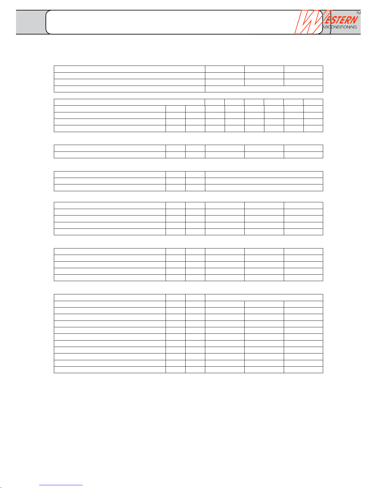
Standard performance data (as per EN 14511) W 35 W 50 W 35 W 50 W 35 W 50
Heat output at B0 kW 5.0 4.6 5.9 5.5 7.7 7.3
COP at B0 - 4.5 3.0 4.5 3.0 4.5 3.0
El. power consumption at B0 kW 1.1 1.6 1.3 1.8 1.7 2.4
Cooling output at B0 kW 3.9 3.0 4.5 3.6 6.0 4.9
Sound
Sound power level Lwa dB(A) 39 39 43
Sound pressure level in 1 m
1)
Lpa dB(A) 24 24 28
Field of application
Heat source temperature min/max °C -6 to +20
Heat flow temperature at > B0 min/max °C +20 to +65
Heat flow temperature at B-6 min/max °C +25 to +60
Vaporiser, brine side (at B0/W35)
Volume flow minimum / nominal / standard m³/h 0.88/1.01/1.17 1.04/1.19/1.39 1.36/1.55/1.81
Pressure drop via heat pump kPa 4/5/7 6/7/9 7/9/11
Free compression 2) kPa 57/55/53 54/52/48 50/47/43
Medium water/ethylene glycol % 75/25 75/25 75/25
Built-in brine pump A 14-1 KW A 14-1 KW A 14-1 KW
Condenser, heater side (at B0/W35)
Volume flow minimum / nominal / standard m³/h 0.43/0.61/0.86 0.51/0.72/1.01 0.66/0.95/1.33
Pressure drop via heat pump kPa 2/4/7 3/5/9 3/5/10
Free compression 2) kPa 51/48/43 49/46/40 48/44/36
Medium water % 100 100 100
Built-in heating pump A 13-1 A 13-1 A 13-1
Dimensions/connections/miscellaneous
Dimensions D x W x H mm 700 x 530 x 1260
Total weight kg 140 140 150
Heating circuit connection AG Inch 5/4" 5/4" 5/4"
Brine circuit connection AG Inch 5/4" 5/4" 5/4"
Cooling agent/filling quantity -- / kg R-410A/1.8 R-410A/1.8 R-410A/1.9
Refrigeration oil filling quantity 0.7 0.7 1.2
Expansion vessel heater
3)
V SD 25.3 SD 25.3 SD 35.3
set upstream pressure, heating circuit p 1.0 1.0 1.0
Expansion vessel, brine circuit V SD 12.3 SD 12.3 SD 18.3
set upstream pressure, brine circuit p 0.5 0.5 0.5
Safety valve (brine/heating) p 3.0 3.0 3.0
Switching point, brine pressure controller p 0.4 0.4 0.4
Heat pump type FUSIO W 5 FUSIO W 6 FUSIO W 8
Model All in One All in One All in One
Controller Optiplus integrated integrated integrated
WPZ-test number SW-311-12-10
FUSIO W 5 - FUSIO W 8 brine/water with Optiplus controller
1) Free field value
2) Free compression is specified for highest level
3) Expansion vessel heater is enclosed from fusio w 11
4) fusio w 5 and fusio w 6 without soft starter
_______________________________________________________________________________
Western Airconditioning B.V. reserves the right to alter specifications
Technical data
FUSIO W 1/2
Page 5
Electrical data
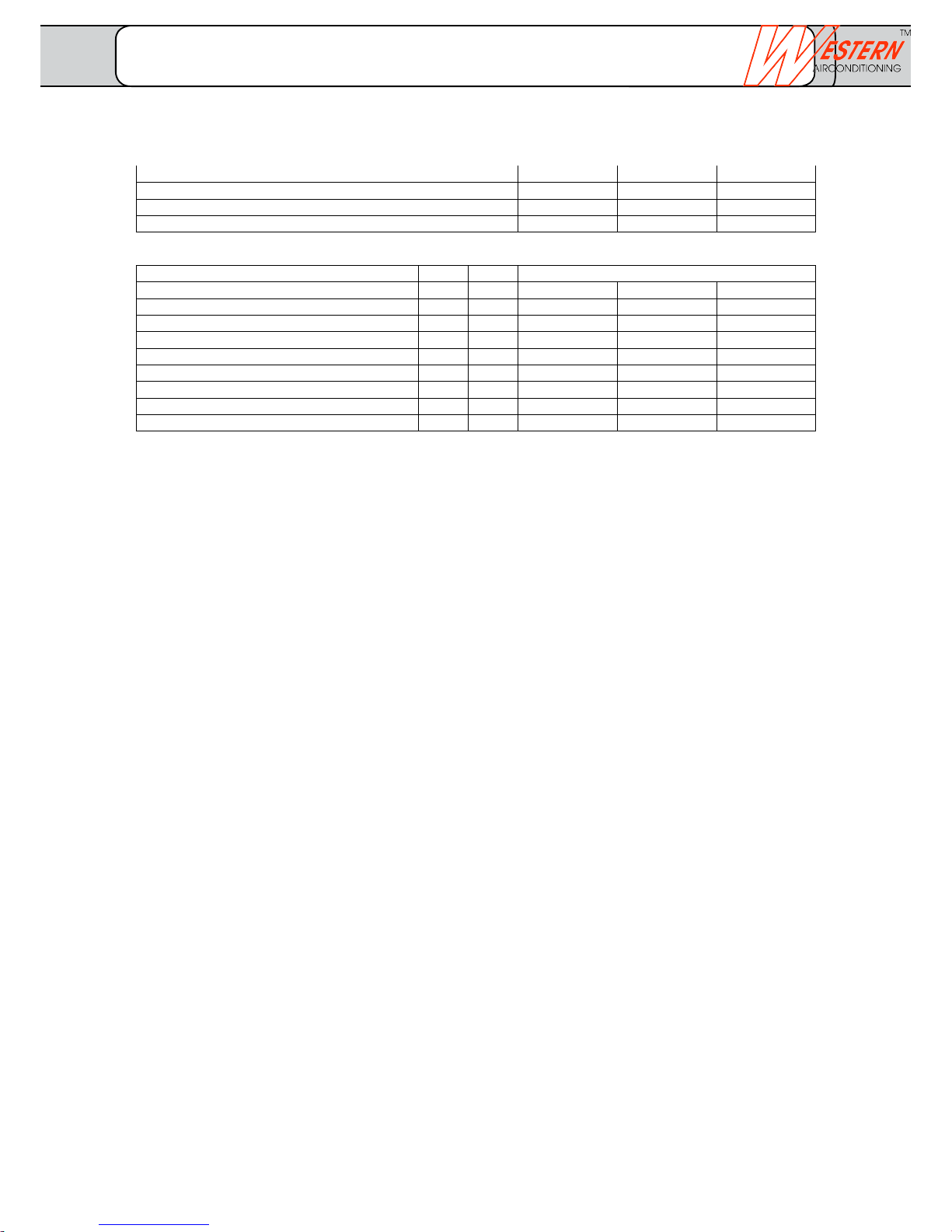
Operating voltage power 3/ N / PE / 400 V / 50 Hz
External Abs. with el. heating insert AT 16 16 20
External Abs. without el. heating insert AT 13 13 13
Output electrical heating insert 400 V kW 2/4/6 2/4/6 2/4/6
max. machine current with el. heating insert A 14.9 15.5 16.5
max. machine current without el. heating insert A 6.3 6.8 7.8
Starting current direct/with soft starter
4)
A 28/-- 28/-- 43/21
Protection class IP 20 20 20
max. power consumption, circulation pumps kW 0.4 0.4 0.5
max. power consumption total kW 8.6 9.1 9.9
Observe local conditions and regulations
Built-in components
Heat pump type FUSIO W 5 FUSIO W 6 FUSIO W 8
One All in One All in One
Controller Optiplus integrated integrated integrated
WPZ-test number ... ... ...
FUSIO W 5 - FUSIO W 8 with Optiplus controller
– Circulation pumps energy class A
– Safety valve 3.0 bar
– Pressure gauge 0–4 bar
– flexible connection-hoses
– Heat pump controller Optiplus
– Temperature sensor
– Expansion vessels (heating vessel enclosed from fusio w 11
– Pressure controller
– Flow sensor
_______________________________________________________________________________
Western Airconditioning B.V. reserves the right to alter specifications
Technical data
FUSIO W 2/2
Page 6
climate
cold heat
Sound
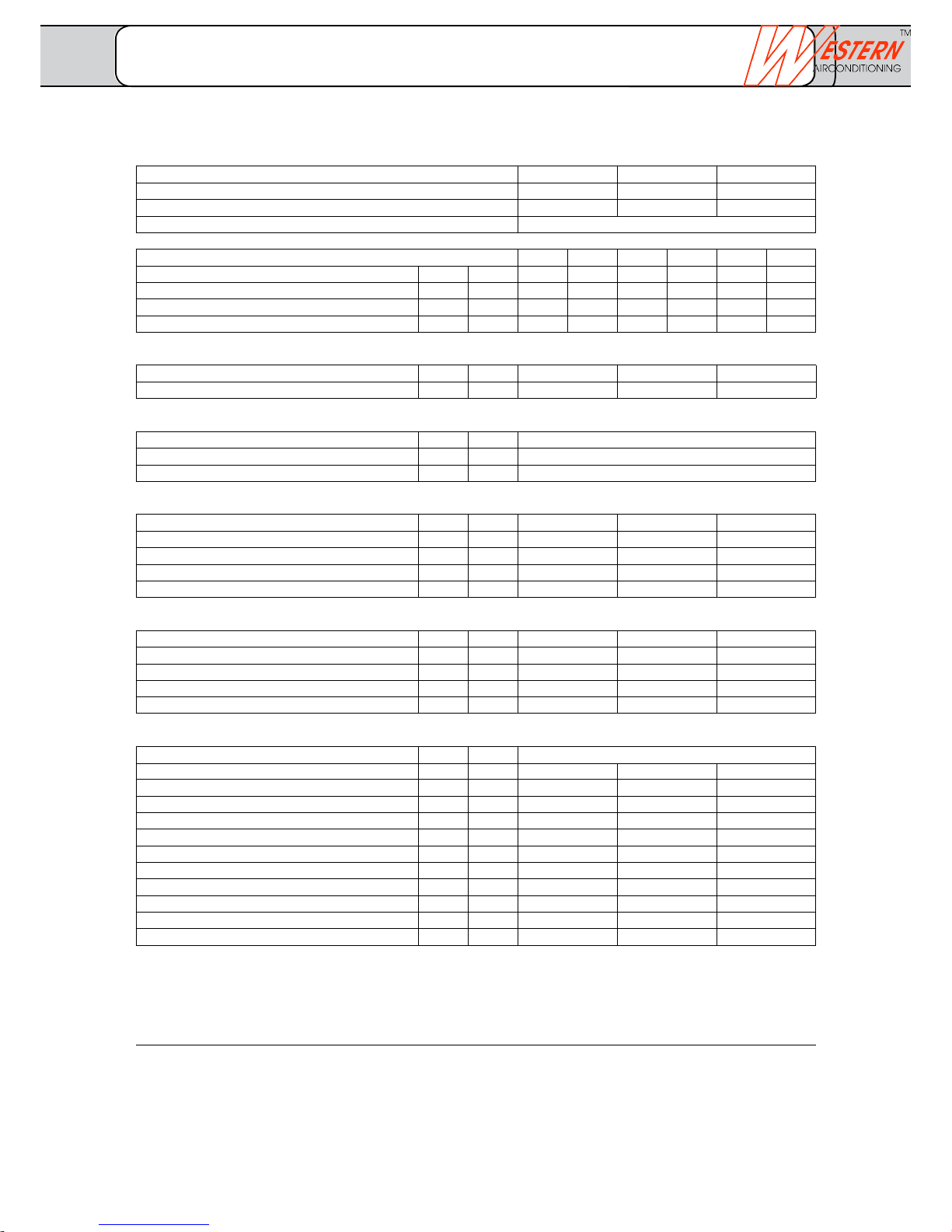
Sound power level Lwa dB(A) 43 47 50
Sound pressure level in 1 m
1)
Lpa dB(A) 28 32 35
Field of application
Heat source temperature min/max °C -6 to +20
Heat flow temperature at > B0 min/max °C +25 to +65
Heat flow temperature at B-6 min/max °C +25 to +60
Vaporiser, brine side (at B0/W35)
Volume flow minimum / nominal / standard m³/h 1.88/2.15/2.51 2.45/2.80/3.27 3.13/3.58/4.18
Pressure drop via heat pump kPa 8/11/14 12/15/20 17/21/29
Free compression
2)
kPa 100/95/91 92/86/80 81/72/59
Medium water/ethylene glycol % 75/25 75/25 75/25
Built-in brine pump A 16-1 KW A 16-1 KW A 16-1 KW
Condenser, heater side (at B0/W35)
Volume flow minimum / nominal / standard m³/h 0.91/1.30/1.81 1.18/1.69/2.36 1.53/2.18/3.06
Pressure drop via heat pump kPa 4/7/13 5/10/18 7/14/27
Free compression
2)
kPa 77/73/61 75/66/52 70/57/36
Medium water % 100 100 100
Built-in heating pump A 15-1 A 15-1 A 15-1
Dimensions/connections/miscellaneous
Dimensions D x W x H mm 700 x 530 x 1260
Total weight kg 170 170 190
Heating circuit connection AG Inch 5/4" 5/4" 5/4"
Brine circuit connection AG Inch 5/4" 5/4" 5/4"
Cooling agent/filling quantity -- / kg R-410A/2.1 R-410A/2.8 R-410A/3.1
Refrigeration oil filling quantity l 1.2 1.2 1.0
Expansion vessel heater
3)
V l SD 50.3 SD 50.3 SD 80.3
set upstream pressure, heating circuit p bar 1.0 1.0 1.0
Expansion vessel, brine circuit V l SD 25.3 SD 25.3 SD 35.3
set upstream pressure, brine circuit p bar 0.5 0.5 0.5
Safety valve (brine/heating) p bar 3.0 3.0 3.0
Switching point, brine pressure controller p bar 0.4 0.4 0.4
Heat pump type FUSIO W 11 FUSIO W 14 FUSIO W 18
Model All in One All in One All in One
Controller Optiplus integrated integrated integrated
WPZ-test number SW-307-12-06
FUSIO W 11 - FUSIO W 18, brine/water with Optiplus controller
Standard performance data (as per EN 14511) W 35 W 50 W 35 W 50 W 35 W 50
Heat output at B0 kW 10.6 9.9 13.8 12.9 17.8 16.7
COP at B0 - 4.7 3.1 4.7 3.1 4.5 3.1
El. power consumption at B0 kW 2.2 3.2 2.9 4.1 3.9 5.4
Cooling output at B0 kW 8.3 6.7 10.9 8.8 13.9 11.3
1) Free field value
2) Free compression is specified for highest level
3) Expansion vessel heater is enclosed from fusio w 11
4) FUSIO W 5 and FUSIO W 6 without soft starter
_______________________________________________________________________________
Western Airconditioning B.V. reserves the right to alter specifications
Technical data
FUSIO W 1/2
Page 7
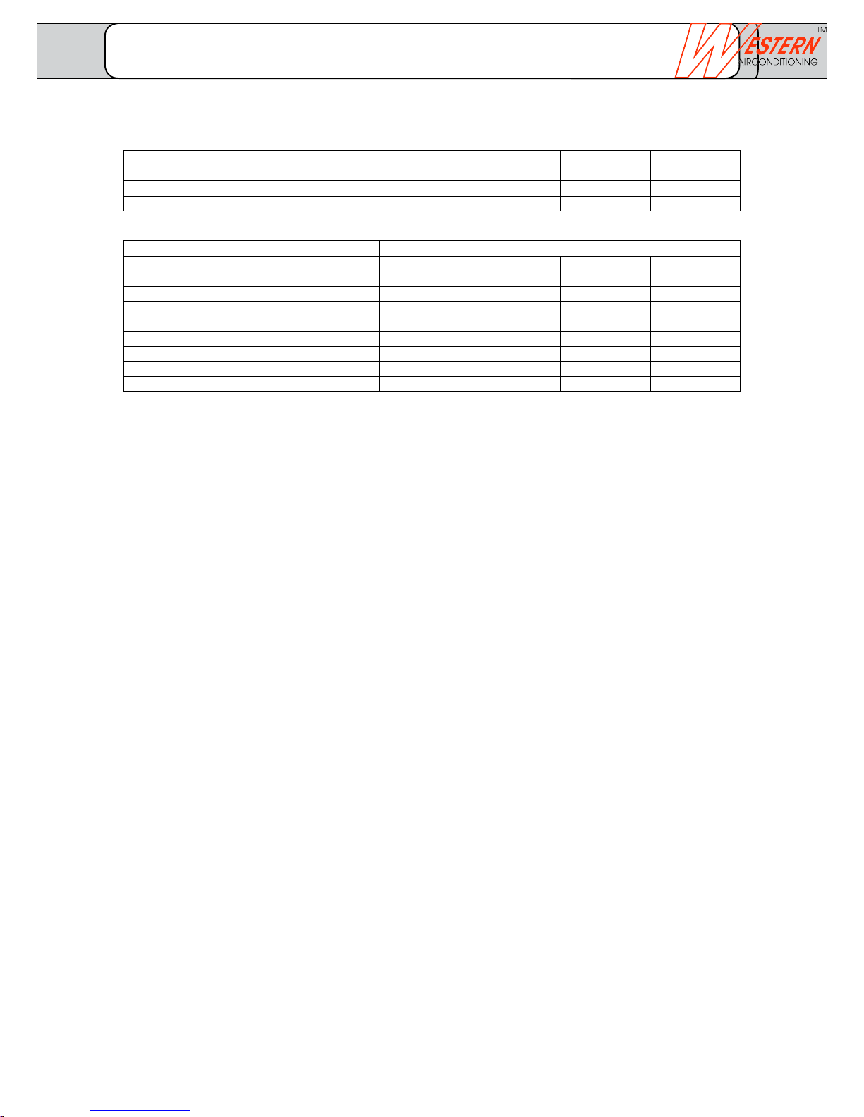
Electrical data
Operating voltage power 3/ N / PE / 400 V / 50 Hz
External Abs. with el. heating insert 20 25 25
External Abs. without el. heating insert 13 16 16
Output electrical heating insert 400 V 2/4/6 2/4/6 2/4/6
max. machine current with el. heating insert 19.1 21.4 24.5
max. machine current without el. heating insert 10.4 12.7 15.8
Starting current direct/with soft starter
4)
52/25 62/30 75/36
Protection class 20 20 20
max. power consumption, circulation pumps 0.5 0.7 0.7
max. power consumption total 10.9 12.6 14.6
Observe local conditions and regulations
Built-in components
Heat pump type FUSIO W 11 FUSIO W 14 FUSIO W 18
Model All in One All in One All in One
Controller Optiplus integrated integrated integrated
WPZ-test number ... ... ...
FUSIO W 11 - FUSIO W 18, brine/water with Optiplus controller
– Circulation pumps energy class A
– Safety valve 3.0 bar
– Pressure gauge 0–4 bar
– flexible connection-hoses
– Heat pump controller Optiplus
– Temperature sensor
– Expansion vessels (heating vessel enclosed from FUSIO W 11
– Pressure controller
– Flow sensor
_______________________________________________________________________________
Western Airconditioning B.V. reserves the right to alter specifications
Technical data
FUSIO W 2/2
Page 8
700
1175
1260
530
240
250
200
1175
485
690
90 290 150
530
700
90
150
150
140
450
450
450
300
1
2
3
4
55
5
5
Tableau
100
7
6
Layout
Electric
Connections
Hot water
Inlet-outlet
Outlet
Heat source
Inlet
Heat source
Inlet-outlet
Hot water inlet
Hot water outlet
Sensor
cable
Feeder
cable
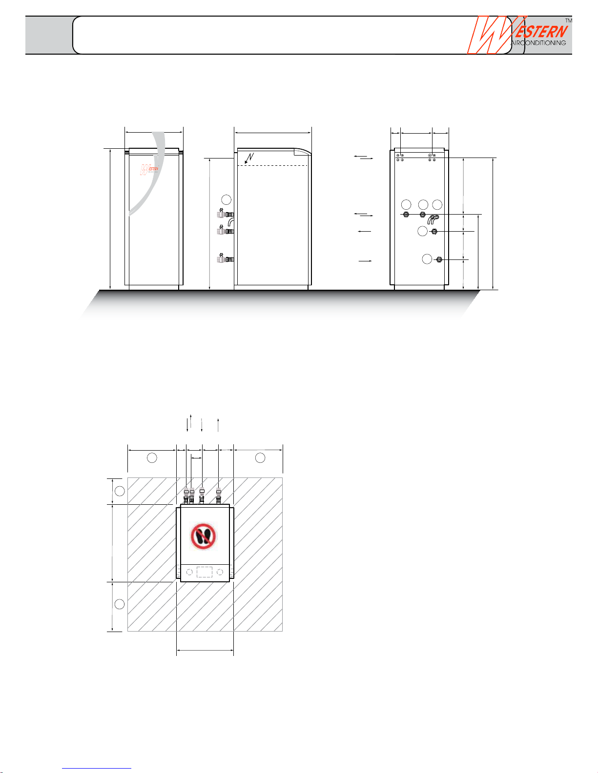
Legend
1 Hot water outlet
2 Hot water inlet
3 Heat source outlet
4 Heat source inlet
5 Minimum distances
6 Outlet of safety valve
from heat source and heater
7 Ball valves
All dimensions are in mm
The external sensor (QAC 34/101) and
the documents are enclosed in the
electric panel.
Front view Lateral view Connection side
Dimension drawings
OH FUSIO W 5- FUSIO W 11, brine/water optiplus controller
Dimension drawing
FUSIO W
_______________________________________________________________________________
Western Airconditioning B.V. reserves the right to alter specifications
Page 9
700
1175
1260
530
240
250
200
1175
485
690
90 290 150
530
700
90
150
150
140
450
450
450
300
1
2
3
4
55
5
5
Tableau
100
6
8
7
8
8
Layout
Electric
Connections
Hot water
Inlet-outlet
Outlet
Heat source
Inlet
Heat source
Inlet-outlet
Hot water inlet
Hot water outlet
Sensor
cable
Feeder
cable
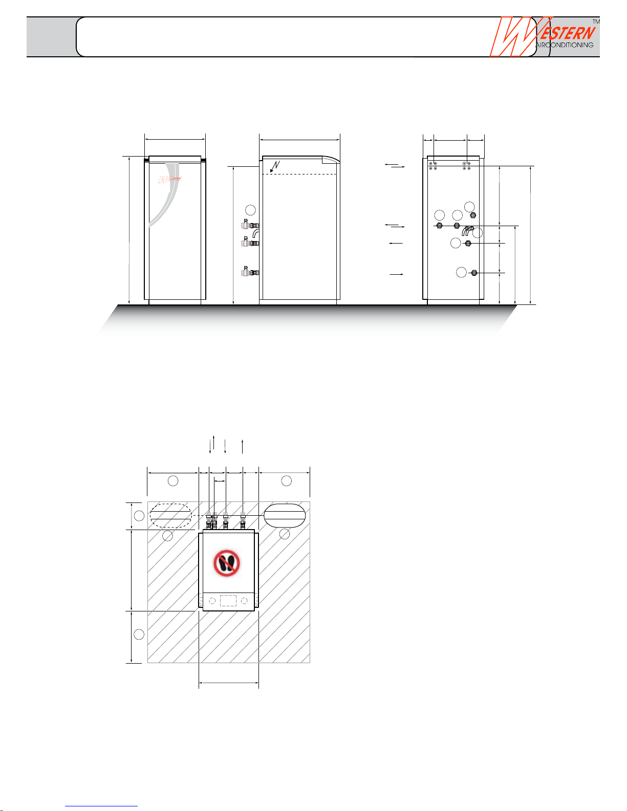
Legend
1 Hot water outlet
2 Hot water inlet
3 Heat source outlet
4 Heat source inlet
5 Minimum distances
6 Outlet of safety valve
from heat source and heater
7 Ball valves
8 Connection expansion vessel heater
1500 mm hose length from the outlet
All dimensions are in mm
The external sensor (QAC 34/101) and the
documents are enclosed in the electric panel.
Front view Lateral view Connection side
Dimension drawing
FUSIO W
FUSIO W 1 - FUSIO W 18, brine/water with Optiplus controller
_______________________________________________________________________________
Western Airconditioning B.V. reserves the right to alter specifications
Page 10
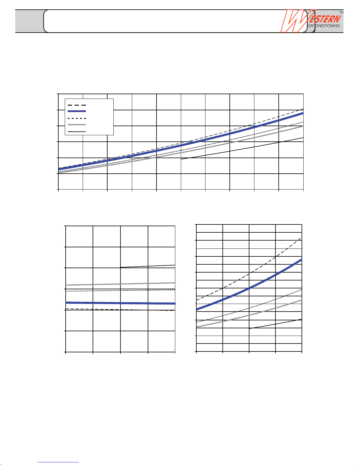
Volume flow source minimum / nominal / standard 0.88/1.01/1.17 m3/h
Volume flow heater minimum / nominal / standard 0.43/0.61/0.86 m3/h
3
4
5
6
7
8
9
-5°C -3°C -1°C 1°C3°C 5°C7°C 9°C11°C13°C15°C
0.0
0.5
1.0
1.5
2.0
2.5
3.0
-5°C 0°C5°C 10°C 15°C
1
2
3
4
5
6
7
8
9
-5°C 0°C5°C 10°C 15°C
Heat output in kW
Heat source temperature
Heat source temperature
Heat source temperature
Electric output in kW Performance data COP
tv = 30°
tv = 35°
tv = 45°
tv = 50°
tv = 63°
Performance data as per EN 14511
Power curves FUSIO W 1- FUSIO W 5
_______________________________________________________________________________
Western Airconditioning B.V. reserves the right to alter specifications
Page 11
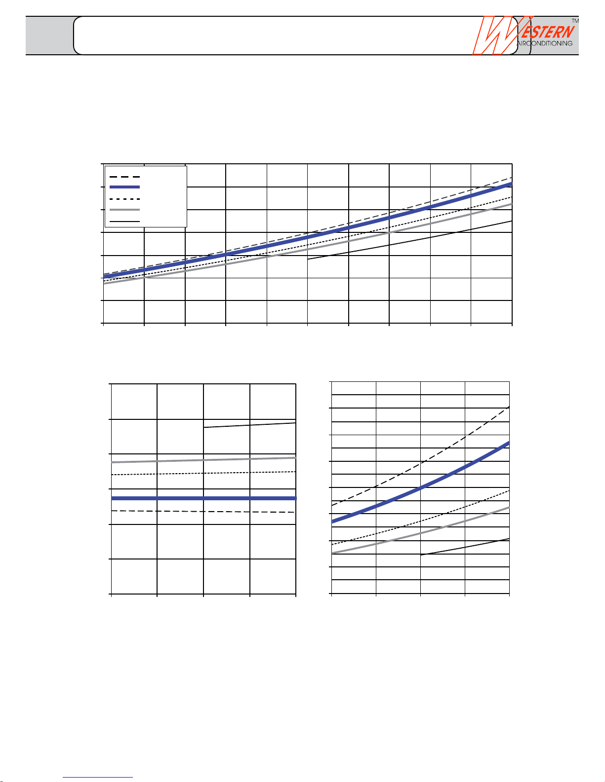
Volume flow source minimum / nominal / standard 1.04/1.19/1.39 m3/h
Volume flow heater minimum / nominal / standard 0.51/0.72/1.01 m3/h
3
4
5
6
7
8
9
10
-5°C -3°C -1°C 1°C3°C 5°C7°C 9°C11° C13°C15°C
0.0
0.5
1.0
1.5
2.0
2.5
3.0
-5°C 0°C5°C 10°C 15°C
1
2
3
4
5
6
7
8
9
-5°C 0°C5°C 10°C 15°C
Heat output in kW
Heat source temperature
Heat source temperature
Heat source temperature
Electric output in kW Performance data COP
tv = 30°
tv = 35°
tv = 45°
tv = 50°
tv = 63°
Performance data as per EN 14511
Power curves
FUSIO W 6
_______________________________________________________________________________
Western Airconditioning B.V. reserves the right to alter specifications
Page 12
climate
cold heat
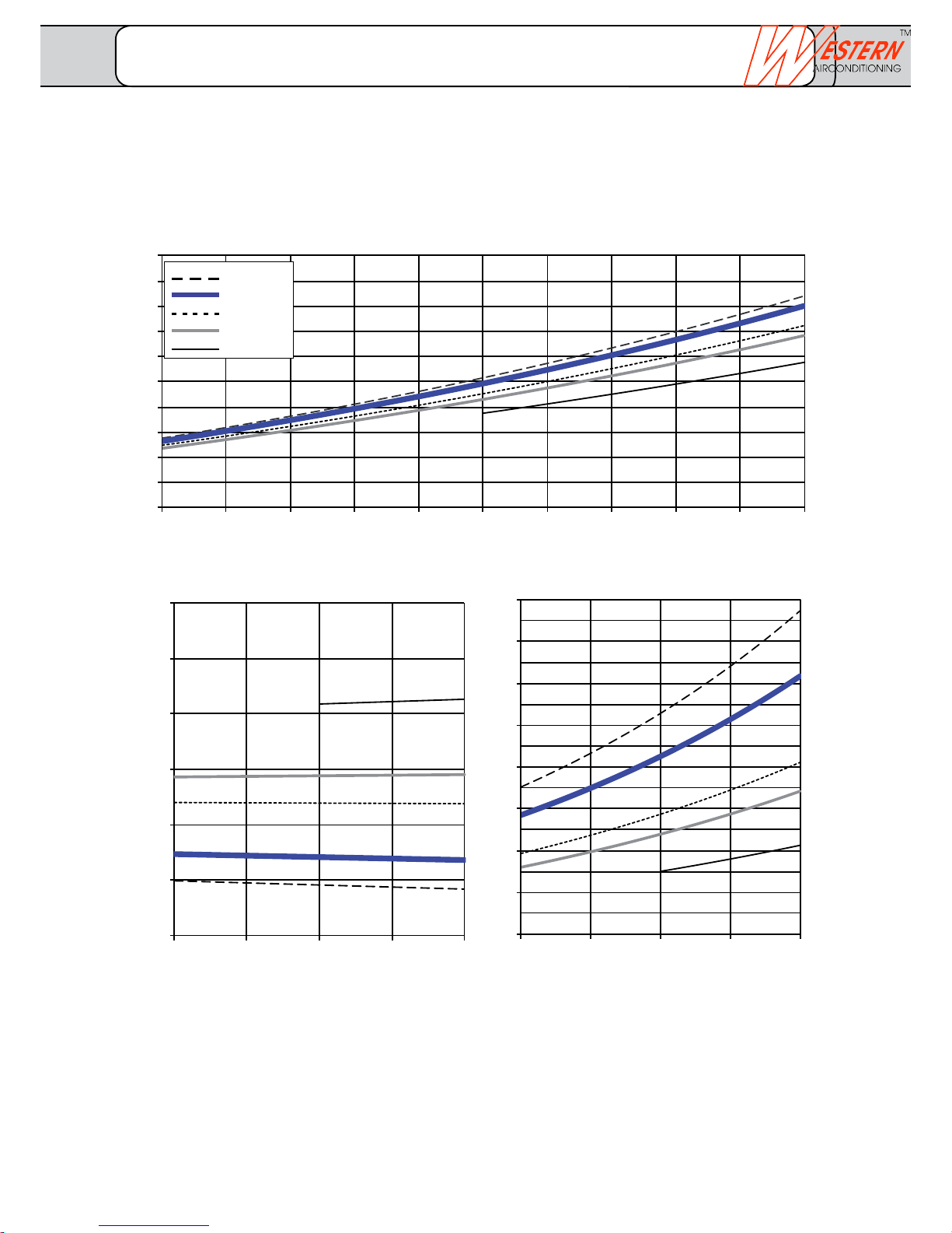
Volume flow source minimum / nominal / standard 1.36/1.55/1.81 m3/h
Volume flow heater minimum / nominal / standard 0.66/0.95/1.33 m3/h
4
5
6
7
8
9
10
11
12
13
14
-5°C -3°C -1°C 1°C3°C 5°C7°C 9°C11°C13°C15°C
1.0
1.5
2.0
2.5
3.0
3.5
4.0
-5°C 0°C5°C 10°C 15°C
1
2
3
4
5
6
7
8
9
-5°C 0°C5°C 10°C 15°C
Heat output in kW
Heat source temperature
Heat source temperature
Heat source temperature
Electric output in kW Performance data COP
tv = 30°
tv = 35°
tv = 45°
tv = 50°
tv = 63°
Performance data as per EN 14511
Power curves
FUSIO W 8
_______________________________________________________________________________
Western Airconditioning B.V. reserves the right to alter specifications
Page 13
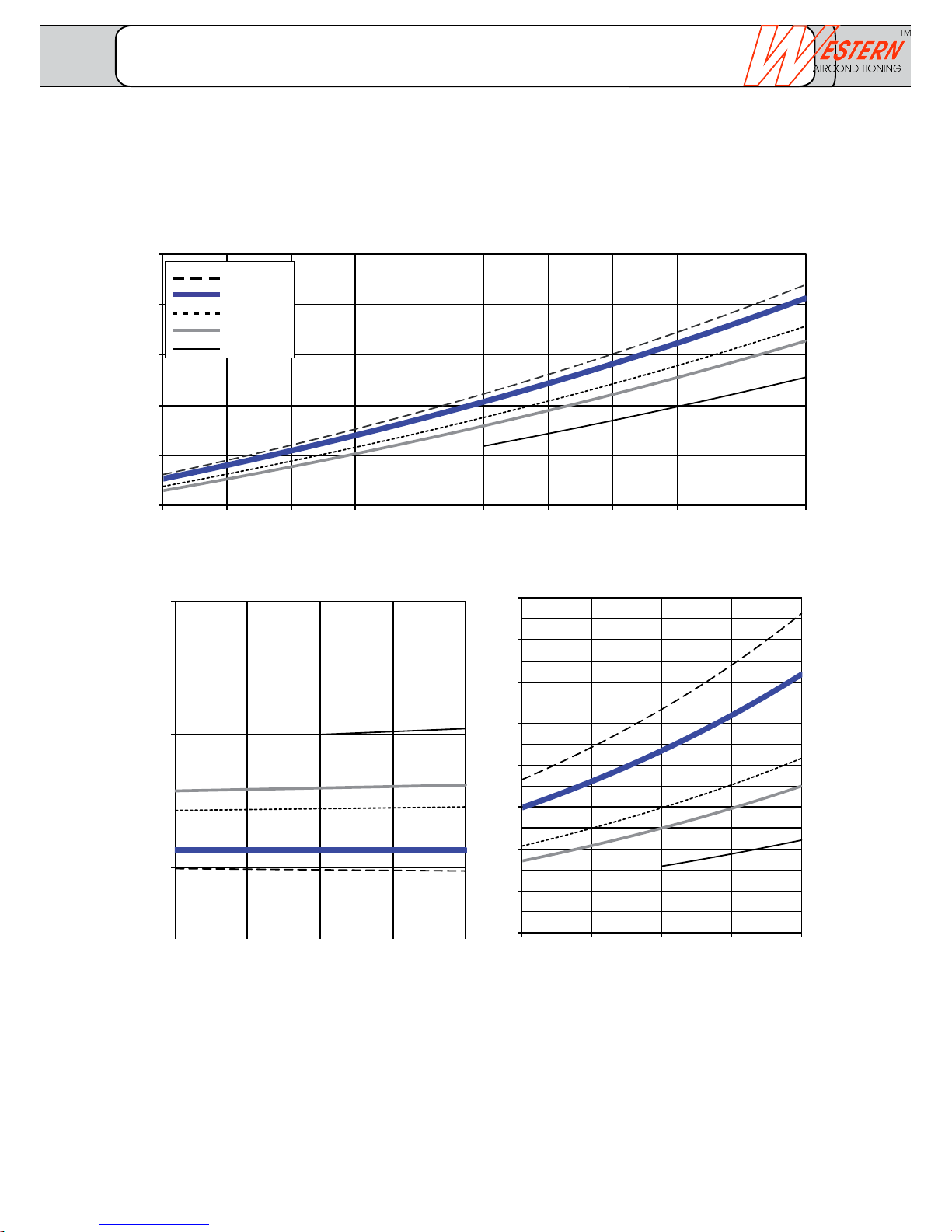
Volume flow source minimum / nominal / standard 1.98/2.15/2.51 m3/h
Volume flow heater minimum / nominal / standard 0.91/1.30/1.91 m3/h
8
10
12
14
16
18
-5°C -3°C -1°C 1°C3°C 5°C7°C 9°C11°C13°C15°C
1.0
2.0
3.0
4.0
5.0
6.0
-5°C 0°C5°C 10°C 15°C
1
2
3
4
5
6
7
8
9
-5°C 0°C5°C 10°C 15°C
Heat output in kW
Heat source temperature
Heat source temperature
Heat source temperature
Electric output in kW Performance data COP
tv = 30°
tv = 35°
tv = 45°
tv = 50°
tv = 63°
Performance data as per EN 14511
Power curves
FUSIO W 11
_______________________________________________________________________________
Western Airconditioning B.V. reserves the right to alter specifications
Page 14
climate
cold heat
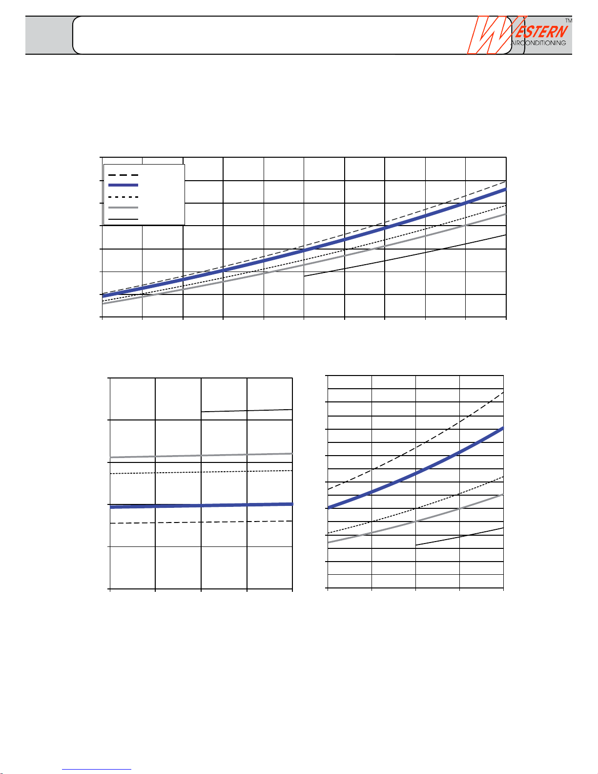
Volume flow source minimum / nominal / standard 2.45/2.80/3.27 m3/h
Volume flow heater minimum / nominal / standard 1.19/1.69/2.36 m3/h
10
12
14
16
18
20
22
24
-5°C -3°C -1°C 1°C3°C 5°C7°C 9°C11°C13°C15°C
1.0
2.0
3.0
4.0
5.0
6.0
-5°C 0°C5°C 10°C 15°C
1
2
3
4
5
6
7
8
9
-5°C 0°C5°C 10°C 15°C
Heat output in kW
Heat source temperature
Heat source temperature
Heat source temperature
Electric output in kW Performance data COP
tv = 30°
tv = 35°
tv = 45°
tv = 50°
tv = 63°
Performance data as per EN 14511
Power curves
FUSIO W 14
_______________________________________________________________________________
Western Airconditioning B.V. reserves the right to alter specifications
Page 15
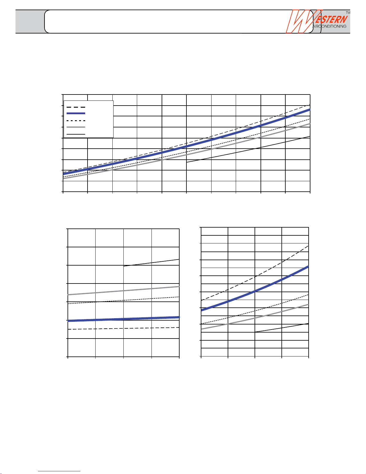
Volume flow source minimum / nominal / standard 3.13/3.58/4.18 m3/h
Volume flow heater minimum / nominal / standard 1.53/2.18/3.06 m3/h
12
14
16
18
20
22
24
26
28
30
-5°C -3°C -1°C 1°C3°C 5°C7°C 9°C11°C13°C15°C
2.0
3.0
4.0
5.0
6.0
7.0
8.0
9.0
-5°C 0°C5°C 10°C 15°C
1
2
3
4
5
6
7
8
9
-5°C 0°C5°C 10°C 15°C
Heat output in kW
Heat source temperature
Heat source temperature
Heat source temperature
Electric output in kW Performance data COP
tv = 30°
tv = 35°
tv = 45°
tv = 50°
tv = 63°
Performance data as per EN 14511
Power curves
FUSIO W 18
_______________________________________________________________________________
Western Airconditioning B.V. reserves the right to alter specifications
Page 16
climate
cold heat
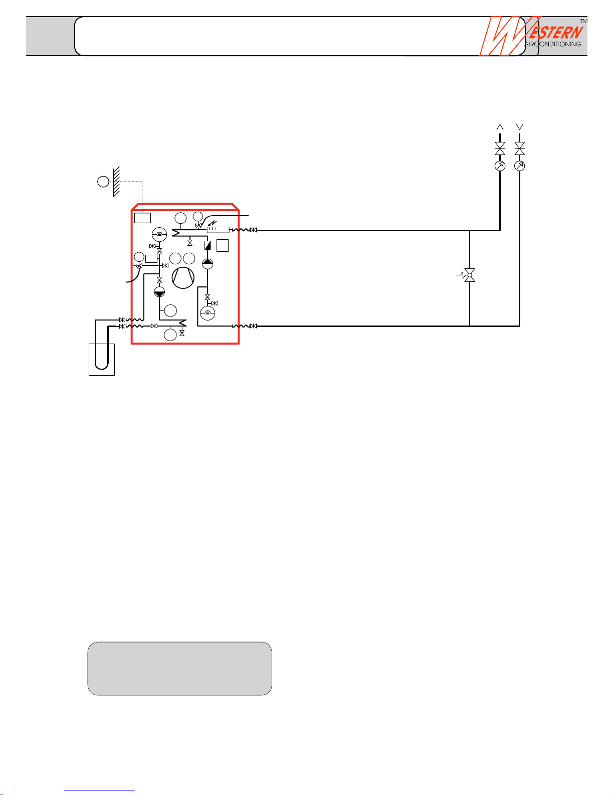
Heat pumps without buffer storage, suitable only for floor heating
Legend
B21 Flow temperature sensor, heat pump
B71 Return flow temperature sensor, heat pump
B9 External temperature sensor
B91 Brine inlet temperature sensor
B92 Brine outlet temperature sensor
EV Expansion vessel
E15 Brine pressure controller
FT Flow sensor
K25 Electric heating insert in flow 6 kW
N1 Heat pump controller Optiplus built-in
PI Pressure gauge
Q8 Built-in brine pump
Q9 Condenser pump built-in
U1 Overflow valve
Function description
Start the heat pump via the external temperature
sensor (B9). This works directly in the heating
circulation.
Depending upon the ambient temperature, the heat
pump is switched on and off via the return flow
temperature (B71). The machine has a starting delay in
order to prevent wobbling.
The integrated electric heating insert (K25) can be
used as emergency heating.
The condenser pump (Q9) is in operation during the
entire heating period.
• Subjecttotechnicalchanges.
• Installationofadditionalcomponents
as per local regulations and conditions.
• Thispresentationisusedasplanningaidforthe
fitter.
Soil sensor system Heat pump Consumer
U1
B9
Q9
EG
N1
Q8
PI
B71
K25
E15
B92
E9, E10
B91
EG
B21
B81
B83
PI
FT
Basic concepts
Basic concept 01.00.10
FUSIO W 5 - FUSIO W 18
_______________________________________________________________________________
Western Airconditioning B.V. reserves the right to alter specifications
Page 17
U1
EG
B9
Q9
EG
N1
Q8
PI
B71
K25
E15
B92
E9, E10
B91
EG
B21
B81
B83
PI
FT
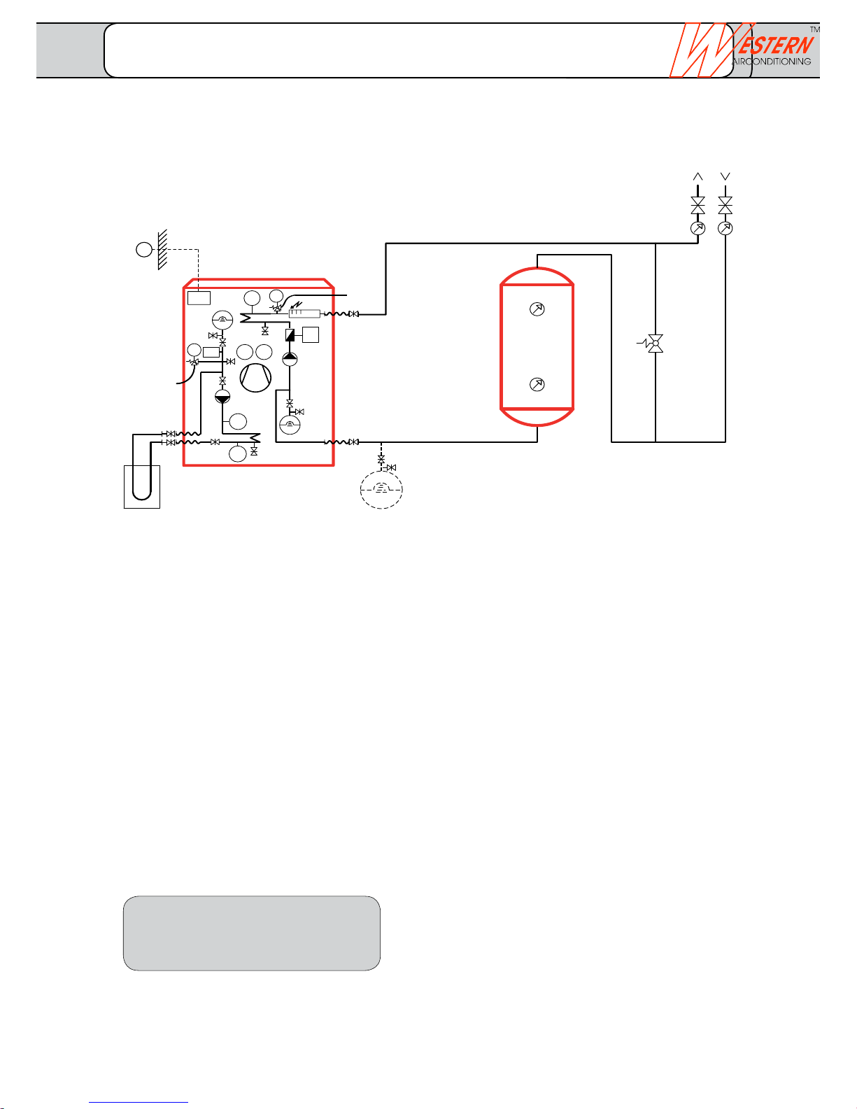
Heat pumps with buffer storage in return flow, suitable only for floor heating
Legend
B21 Flow temperature sensor, heat pump
B71 Return flow temperature sensor, heat pump
B9 External temperature sensor
B91 Brine inlet temperature sensor
B92 Brine outlet temperature sensor
EV Expansion vessel
E15 Brine pressure controller
FT Flow sensor
K25 Electric heating insert in flow 6 kW
N1 Heat pump controller Optiplus built-in
PI Pressure gauge
Q9 Condenser pump built-in
Q8 Built-in brine pump
U1 Overflow valve
Function description
Start the heat pump via the external temperature sensor
(B9). This works directly in the heating circulation. A buffer
storage is integrated in the return flow.
Depending upon the ambient temperature, the heat
pump is switched on and off via the return flow
temperature (B71). The machine has a starting delay in
order to prevent wobbling.
The integrated electric heating insert (K25) can be used
as emergency heating.
The condenser pump (Q9) is in operation during the entire
heating period.
The size of the built-in expansion vessel (EV) must be
controlled and depending upon the water content must
be supplemented with an external vessel.
• Subjecttotechnicalchanges.
• Installationofadditionalcomponents
as per local regulations and conditions.
• Thispresentationisusedasplanningaidforthe
fitter.
Soil sensor system Heat pump ConsumerBuffer storage
System-specific
Basic concept 01/01/2010
FUSIO W 5 - FUSIO W 18
_______________________________________________________________________________
Western Airconditioning B.V. reserves the right to alter specifications
Page 18
climate
cold heat
KW
TWW
Q3
B3
U1
K6
1)
SV
B9
Q9
EG
N1
Q8
PI
B71
K25
E15
B92
E9, E10
B91
EG
B21
B81
B83
PI
FT
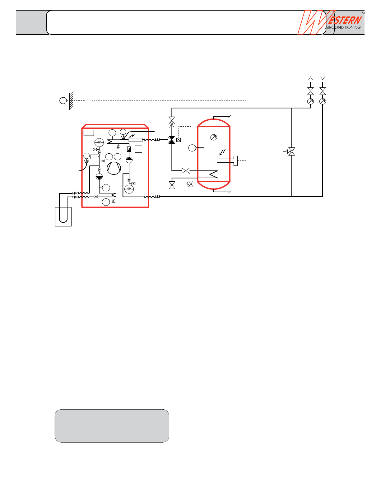
Legend
B21 Flow temperature sensor heat pump
B3 Domestic water temperature sensor
B71 Return flow temperature sensor, heat pump
B9 External temperature sensor
B91 Brine inlet temperature sensor
B92 Brine outlet temperature sensor
EV Expansion vessel
E15 Brine pressure controller
FT Flow sensor
CW Cold water
K6 Electric heating insert DHW 1)
K25 Electric heating insert in flow 6 kW
N1 Heat pump controller Optiplus built-in
PI Pressure gauge
Q3 Deflector valve DHW
Q8 Built-in brine pump
Q9 Condenser pump built-in
BV Balancing valve
SV Safety valve
DHW Domestic hot water
U1 Overflow valve
1) Power contactor+fuse in on-site tableau
Function description
Start the heat pump via the external temperature sensor (B9).
This works directly in the heating circulation.
Depending upon the ambient temperature, the heat pump is
switched on and off via the return flow temperature (B71). The
machine has a starting delay in order to prevent wobbling.
The integrated electric heating insert (K25) can be used as
emergency heating.
The condenser pump (Q9) is in operation during the entire
heating period.
DHW is charged according to the time program via the
temperature sensor (B3), the deflector valve (Q3) is thus
switched. The electrical insert (K6) in the DHW storage is
controlled by the heat pump controller.
• Subjecttotechnicalchanges.
• Installationofadditionalcomponents
as per local regulations and conditions.
• Thispresentationisusedasplanningaidforthe
fitter.
Soil sensor system Heat pump ConsumerDomestic water storage tankCharging circuit DHW
Basic concept 01.20.10
FUSIO W 5 - FUSIO W 18
Heat pumps without buffer storage, suitable only for floor heating
DHW heating with hydraulic switchover
_______________________________________________________________________________
Western Airconditioning B.V. reserves the right to alter specifications
Page 19
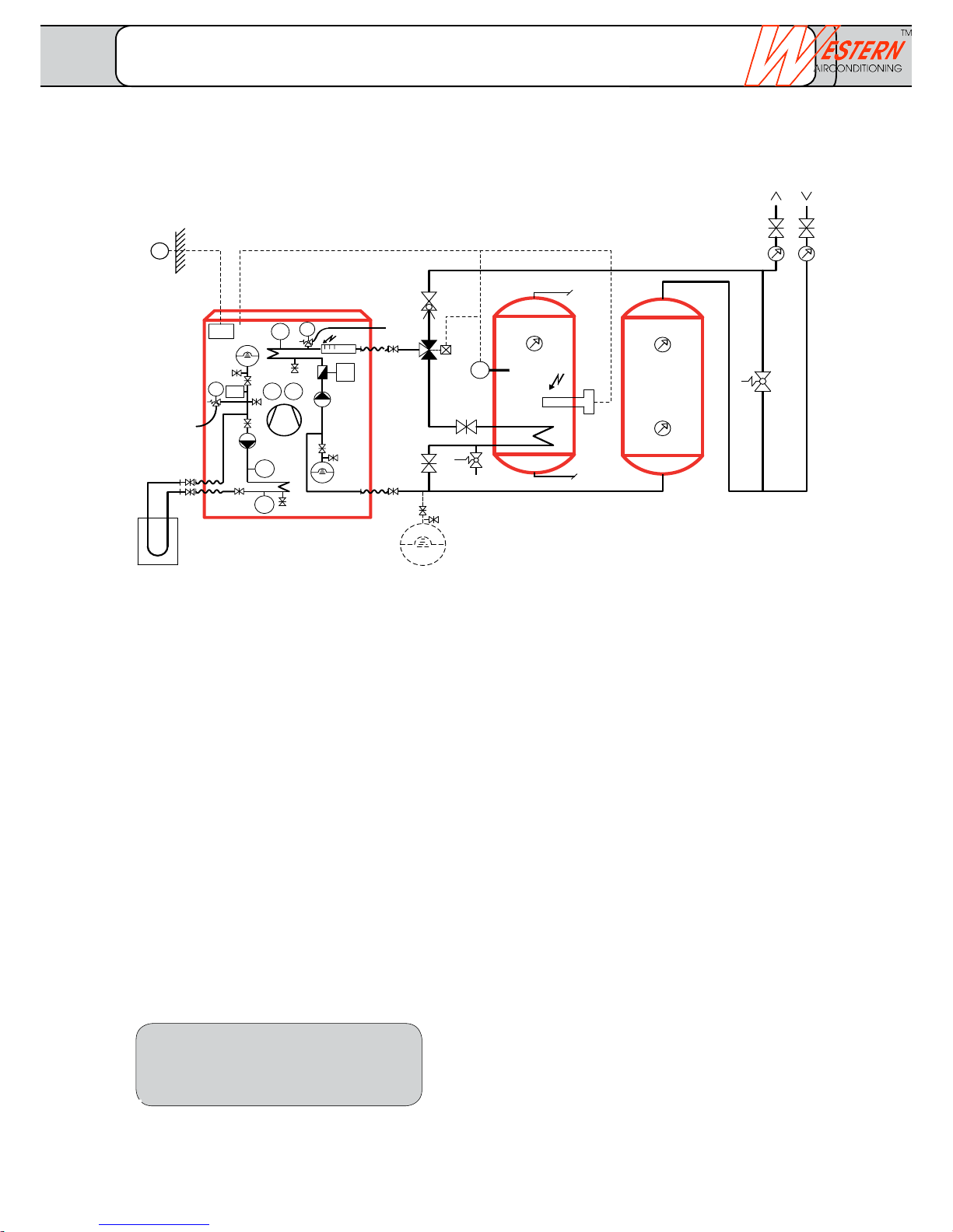
KW
TWW
Q3
K6
1)
U1
SV
B3
EG
SRV
B9
Q9
EG
N1
Q8
PI
B71
K25
E15
B92
E9, E10
B91
EG
B21
B81
B83
PI
FT
Heat pumps with buffer storage in return flow, suitable only for floor heating
DHW heating with hydraulic switchover
Legend
B21 Flow temperature sensor heat pump
B3 Domestic water temperature sensor
B71 Return flow temperature sensor, heat pump
B9 External temperature sensor
B91 Brine inlet temperature sensor
B92 Brine outlet temperature sensor
EV Expansion vessel
E15 Brine pressure controller
FT Flow sensor
CW Cold water
K6 Electric heating insert DHW 1)
K25 Electric heating insert in flow 6 kW
N1 Heat pump controller Optiplus built-in
PI Pressure gauge
Q3 Deflector valve DHW
Q8 Built-in brine pump
Q9 Condenser pump built-in
BV Balancing valve
SV Safety valve
DHW Domestic hot water
U1 Overflow valve
1) Power contactor+fuse in on-site tableau
Function description
Start the heat pump via the external temperature
sensor (B9). This works directly in the heating
circulation. A buffer storage is integrated in the return
flow.
Depending upon the ambient temperature, the heat
pump is switched on and off via the return flow
temperature (B71). The machine has a starting delay in
order to prevent wobbling.
The integrated electric heating insert (K25) can be used
as emergency heating. The condenser pump (Q9) is in
operation during the entire heating period.
The size of the built-in expansion vessel (EV) must be
controlled and depending upon the water content must
be supplemented with an external vessel.
DHW is charged according to the time program via the
temperature sensor (B3), the deflector valve (Q3) is thus
switched. The electrical insert (K6) in the DHW storage
is controlled by the heat pump controller.
• Subjecttotechnicalchanges.
• Installationofadditionalcomponents
as per local regulations and conditions.
• Thispresentationisusedasplanningaidforthe
fitter.
Soil sensor system Heat pump ConsumerBuffer storageDomestic water
storage tank
Charging circuit DHW
System-specific
Basic concept 01.21.10
FUSIO W 5 - FUSIO W 18
_______________________________________________________________________________
Western Airconditioning B.V. reserves the right to alter specifications
Page 20
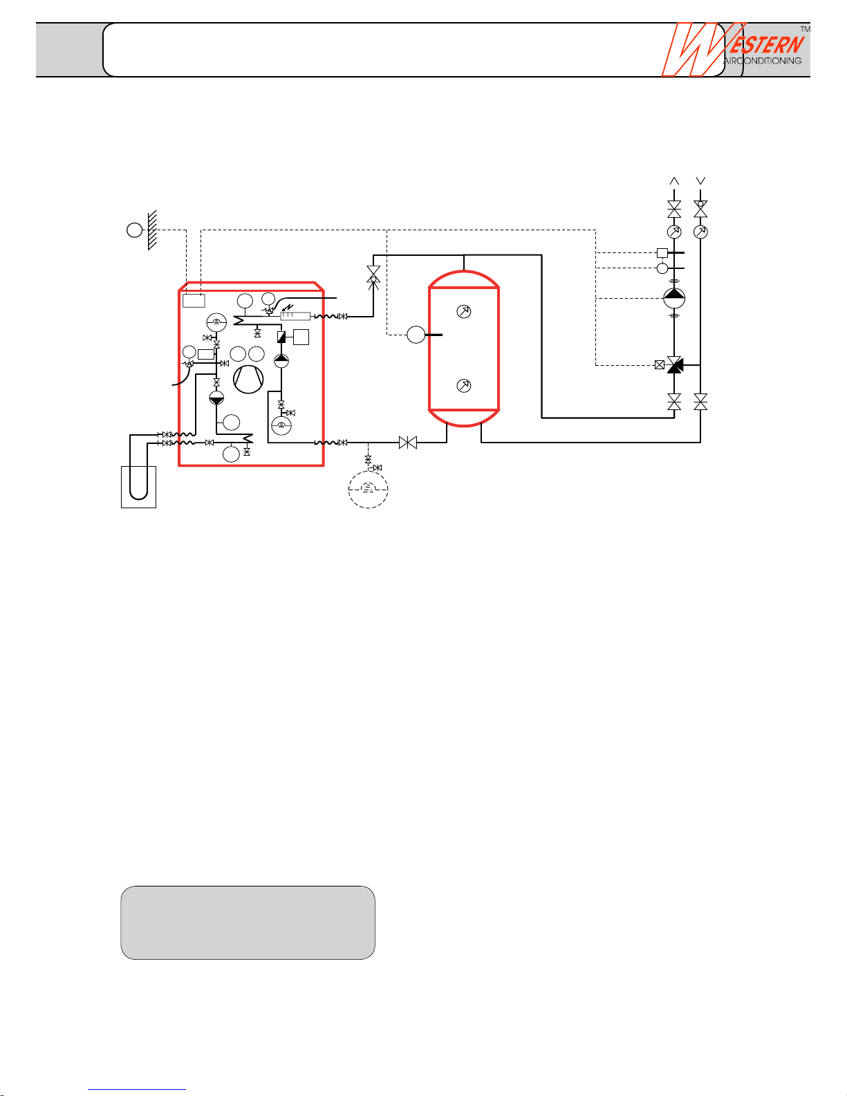
climate
cold heat
Q2
B4
Y1
B1
ST
B9
Q9
EG
N1
Q8
PI
B71
K25
E15
B92
E9, E10
B91
EG
B21
B81
B83
PI
FT
SRV
EG
SRV
Heat pump with buffer storage
Charging initiated as per the ambient temperature
Legend
B1 Flow temperature sensor heating circuit
B21 Flow temperature sensor heat pump
B4 Buffer storage temperature sensor
B71 Return flow temperature sensor, heat pump
B9 External temperature sensor
B91 Brine inlet temperature sensor
B92 Brine outlet temperature sensor
EV Expansion vessel
E15 Brine pressure controller
FT Flow sensor
K25 Electric heating insert in flow 6 kW
N1 Heat pump controller Optiplus built-in
PI Pressure gauge
Q2 Heating circuit pump on-site
Q8 Built-in brine pump
Q9 Condenser pump built-in
BV Balancing valve
ST Safety thermostat
Y1 Heating circuit mixer
Function description
Start the heat pump via the external temperature
sensor (B9). This works on the buffer storage.
Depending upon the ambient temperature, the heat
pump is switched on and off via the temperature
sensor (B4) or (B71). The machine has a starting delay
in order to prevent wobbling.
The integrated electric heating insert (K25) can be used
as emergency heating. The pump (Q2) is in operation
during the entire heating period.
The size of the built-in expansion vessel (EV) must be
controlled and depending upon the water content must
be supplemented with an external vessel.
The discharge circuit control is controlled with the
optional heating circuit mixer (Y1) via the flow
temperature sensor (B1) depending upon the outside
temperature. The buffer storage can be charged at
reduced rate.
• Subjecttotechnicalchanges.
• Installationofadditionalcomponents
as per local regulations and conditions.
• Thispresentationisusedasplanningaidforthe
fitter.
Soil sensor system Heat pump ConsumerBuffer storageCharging circuit
heater
System-specific
Basic concept 02.00.10
FUSIO W 5 - FUSIO W 18
_______________________________________________________________________________
Western Airconditioning B.V. reserves the right to alter specifications
Page 21
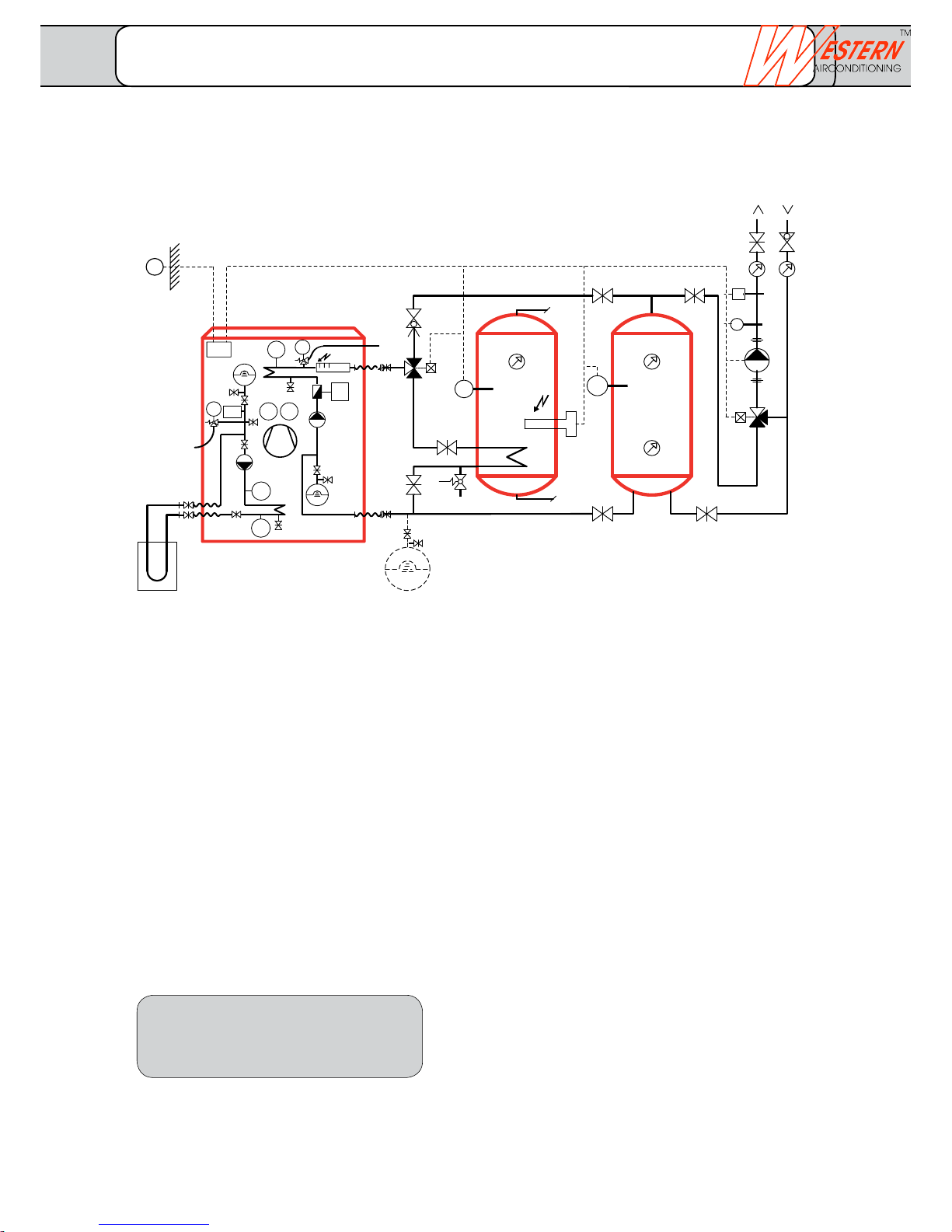
KW
TWW
1)
K6
Q3
B4
SV
SRV
SRV
Q2
Y1
B1
ST
B3
EG
B9
Q9
EG
N1
Q8
PI
B71
K25
E15
B92
E9, E10
B91
EG
B21
B81
B83
PI
FT
Heat pump with buffer storage
DHW heating with hydraulic switchover
Legend
B1 Flow temperature sensor heating circuit
B21 Flow temperature sensor, heat pump
B3 Domestic hot water temperature sensor
B4 Buffer storage temperature sensor
B71 Return flow temperature sensor, heat pump
B9 External temperature sensor
B91 Brine inlet temperature sensor
B92 Brine outlet temperature sensor
EV Expansion vessel
E15 Brine pressure controller
FT Flow sensor
CW Cold water
K6 Electric heating insert DHW 1)
K25 Electric heating insert in flow 6 kW
N1 Heat pump controller Optiplus built-in
PI Pressure gauge
Q2 Heating circuit pump on-site
Q3 Deflector valve DHW
Q8 Built-in brine pump
Q9 Condenser pump built-in
BV Balancing valve
ST Safety thermostat
SV Safety valve
DHW Domestic hot water
Y1 Heating circuit mixer
1) Power contactor and fuse in on-site tableau
Function description
Start the heat pump via the external temperature sensor
(B9). This works on the buffer storage.
Depending upon the ambient temperature, the heat pump is
switched on and off via the temperature sensor (B4) or
(B71). The machine has a starting delay in order to prevent
wobbling. The integrated electric heating insert (K25) can be
used as emergency heating.
The pump (Q2) is in operation during the entire heating
period.
DHW is charged according to the time program via the
temperature sensor (B3), the deflector valve (Q3) is thus
switched. The electrical insert (K6) in the DHW storage is
controlled by the heat pump controller.
The size of the built-in expansion vessel (EV) must be
controlled and depending upon the water content must be
supplemented with an external vessel.
Depending upon the ambient temperature, the discharge
circuit control is controlled with the optional heating
circuit mixer (Y1) via the flow temperature sensor (B1). The
buffer storage can be charged at reduced rate.
• Subjecttotechnicalchanges.
• Installationofadditionalcomponents
as per local regulations and conditions.
• Thispresentationisusedasplanningaidforthe
fitter.
Soil sensor system Heat pump ConsumerBuffer storageDomestic water
storage tank
Charging circuit
DHW/heater
System-specific
Basic concept 02.20.10
FUSIO W 5 - FUSIO W 18
_______________________________________________________________________________
Western Airconditioning B.V. reserves the right to alter specifications
Page 22
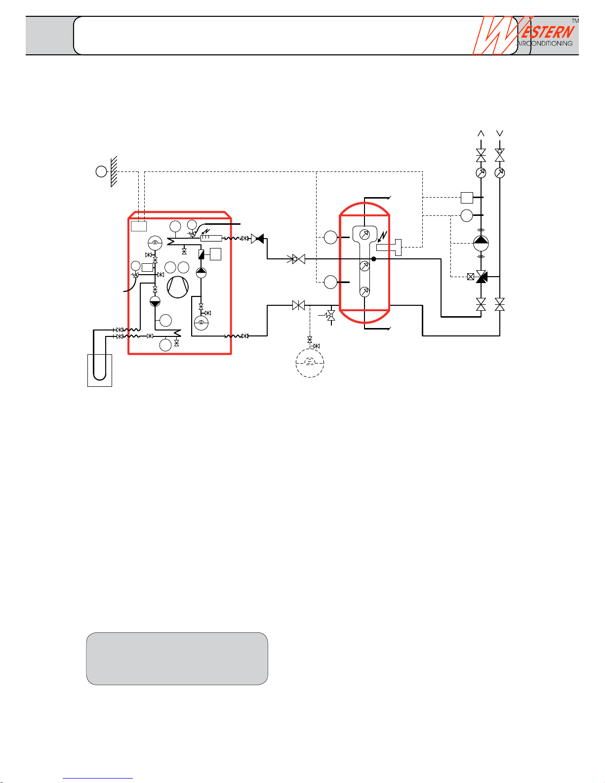
climate
cold heat
KW
TWW
1)
K6
Y1
B3
Q2
B1
ST
SV
B4
EG
SRV
SRV
RSV
B9
Q9
EG
N1
Q8
PI
B71
K25
E15
B92
E9, E10
B91
EG
B21
B81
B83
PI
FT
Heat pump with combination storage, DHW heating at reduced rate
Zonal charging initiated as per the ambient temperature
Legend
B1 Flow temperature sensor heating circuit
B21 Flow temperature sensor, heat pump
B3 Domestic hot water temperature sensor
B4 Buffer storage temperature sensor
B71 Return flow temperature sensor, heat pump
B9 External temperature sensor
B91 Brine inlet temperature sensor
B92 Brine outlet temperature sensor
EV Expansion vessel
E15 Brine pressure controller
FT Flow sensor
CW Cold water
K6 Electric heating insert DHW 1)
K25 Electric heating insert in flow 6 kW
N1 Heat pump controller Optiplus built-in
PI Pressure gauge
Q2 Heating circuit pump on-site
Q8 Built-in brine pump
Q9 Condenser pump built-in
NRV Non-return valve
ST Safety thermostat
SV Safety valve
DHW Domestic hot water
Y1 Heating circuit mixer
1) Power contactor+fuse in on-site tableau
Function description
Start the heat pump via the external temperature sensor
(B9). This works in the lower zone of the combination
storage.
Depending upon the ambient temperature, the heat
pump is switched on and off via the temperature sensor
(B4) or (B71). The machine has a starting delay in order to
prevent wobbling. The integrated electric heating insert
(K25) can be used as emergency heating. The discharge
circuit control integrated in the heat pump controller is
initiated as per the ambient temperature and is controlled
via the flow temperature (B1).
The pump (Q2) is in operation during the entire heating
period. The size of the built-in expansion vessel (EV)
must be controlled and depending upon the water
content must be supplemented with an external vessel.
The combination storage can be charged at reduced rate.
DHW is charged as per the time program via the
temperature sensor (B3). The electrical insert (K6) in the
combination storage is controlled by the heat pump
controller.
• Subjecttotechnicalchanges.
• Installationofadditionalcomponents
as per local regulations and conditions.
• Thispresentationisusedasplanningaidforthe
fitter.
Soil sensor system Heat pump ConsumerCombination storageCharging circuit
Combination storage
System-specific
Basic concept 02.30.10
FUSIO W 5 - FUSIO W 18
_______________________________________________________________________________
Western Airconditioning B.V. reserves the right to alter specifications
Page 23
KW
TWW
K6
1)
2)
Y1
2)
B3
B4
Q2
B1
ST
SV
SRV
SRV
RSV
EG
B9
Q9
EG
N1
Q8
PI
B71
K25
E15
B92
E9, E10
B91
EG
B21
B81
B83
PI
FT
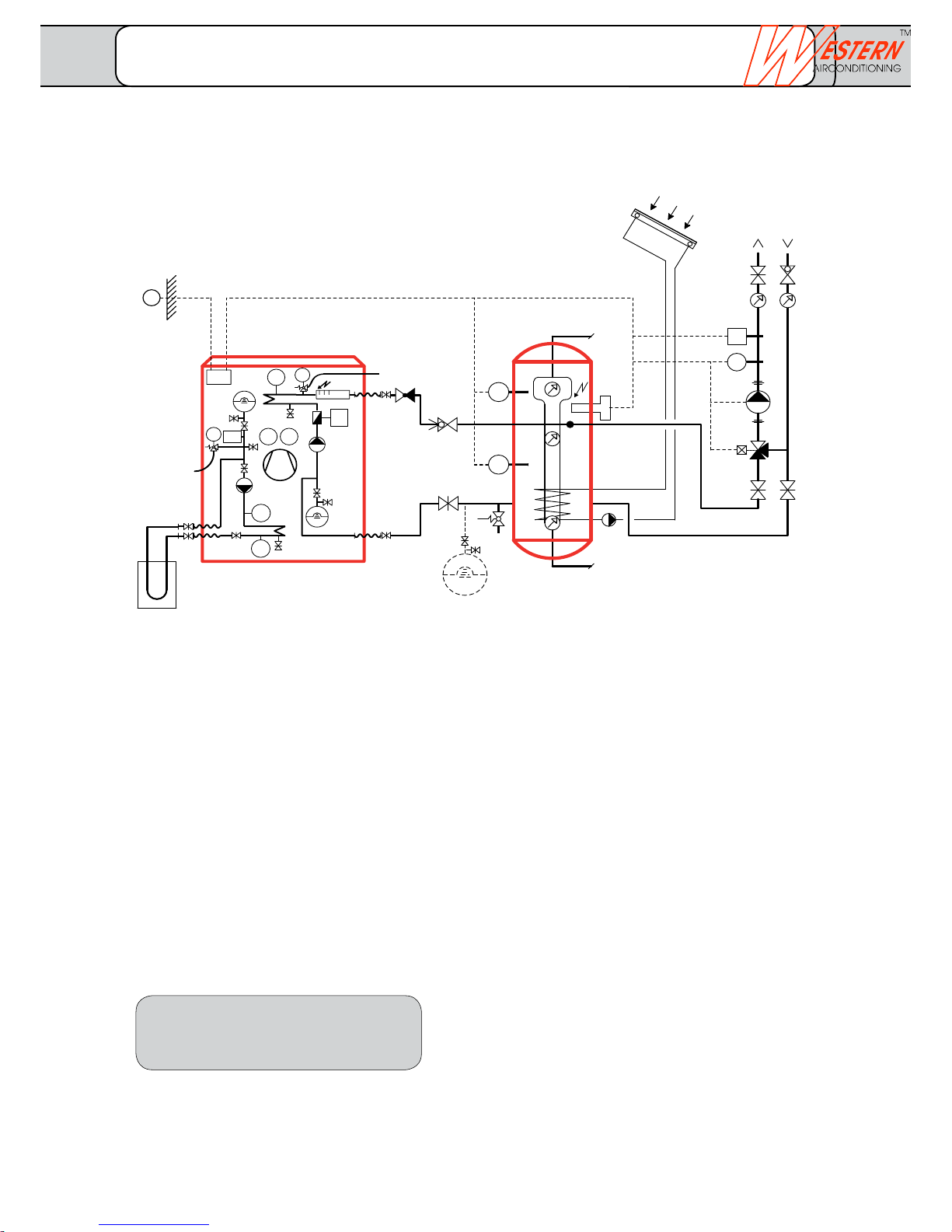
Heat pump monovalent with solar combination storage, DHW heating at reduced rate
Zonal charging initiated as per the ambient temperature
Legend
B1 Flow temperature sensor heating circuit
B21 Flow temperature sensor, heat pump
B3 Domestic water temperature sensor
B4 Buffer storage temperature sensor
B71 Return flow temperature sensor, heat pump
B9 External temperature sensor
B91 Brine inlet temperature sensor
B92 Brine outlet temperature sensor
EV Expansion vessel
E15 Brine pressure controller
FT Flow sensor
CW Cold water
K6 Electric heating insert DHW 1)
K25 Electric heating insert in flow 6 kW
N1 Heat pump controller Optiplus built-in
PI Pressure gauge
Q2 Heating circuit pump on-site
Q8 Brine pump
Q9 Condenser pump
NRV Non-return valve
ST Safety thermostat
BV Balancing valve
SV Safety valve
DHW Domestic hot water
Y1 Heating circuit mixer
1) Power contactor+fuse in on-site tableau
2) Solar system on-site, independent of control
by heat pump.
Function description
Start the heat pump via the external temperature sensor
(B9). This works in the lower zone of the combination
storage.
Depending upon the ambient temperature, the heat
pump is switched on and off via the temperature sensor
(B4) or (B71). The machine has a starting delay in order
to prevent wobbling. The integrated electric heating insert
(K25) can be used as emergency heating. The discharge
circuit control integrated in the heat pump controller is
initiated as per the ambient temperature and is controlled
via the flow temperature (B1).
The pump (Q2) is in operation during the entire heating
period. The size of the built-in expansion vessel (EV) must
be controlled and depending upon the water content of
the heating system, the same must be supplemented
with an external vessel. The combination storage can be
charged at reduced rate.
DHW is charged as per the time program via the
temperature sensor (B3). The electrical insert (K6) in the
combination storage is controlled by the heat pump
controller. The lower part of the combination storage is
managed by the solar system, which is independent of
the heat pump.
• Subjecttotechnicalchanges.
• Installationofadditionalcomponents
as per local regulations and conditions.
• Thispresentationisusedasplanningaidforthe
fitter.
Soil sensor system Heat pump ConsumerSolar systemCombination
storage
Charging circuit
Combination storage
System-specific
Basic concept 02.40.10
FUSIO W 5 - FUSIO W 18
_______________________________________________________________________________
Western Airconditioning B.V. reserves the right to alter specifications
Page 24
climate
cold heat
Y1
Q2
B1
ST
QX2
Zu
Auf
PE
N
M
1~
L
PE
N
M
1~
L
PE
N
QX4
PE
N
QX2
QX1
Q9
Q8
W
V
U
QX3
Y2
Y1
T
Q2
S
Q3
w
M
M
M
BX1
M
M
B91
M
B71
M
B1
M
B21
M
B9
u
t
s
r
q
p
n
k
X
Y
PE
N
PE
N
PE
N
PE
N
PE
N
PE
N
Regler Optiplus (RVS 61/3)
3
2
U
3
2
V
2
W
4
3
3
3
2
X
2
Y
2
T
4
3
2
Z
4
3
3
2
S
3
w
2
u
2
t
2
z
2
y
2
x
2
s
2
r
2
q
2
p
2
n
2
k
2
BX3
BX2
B92
PE
QX6
QX5
N
Z
x
y
z
M
BX4
M
M
UX1
SRV SRV
UX2
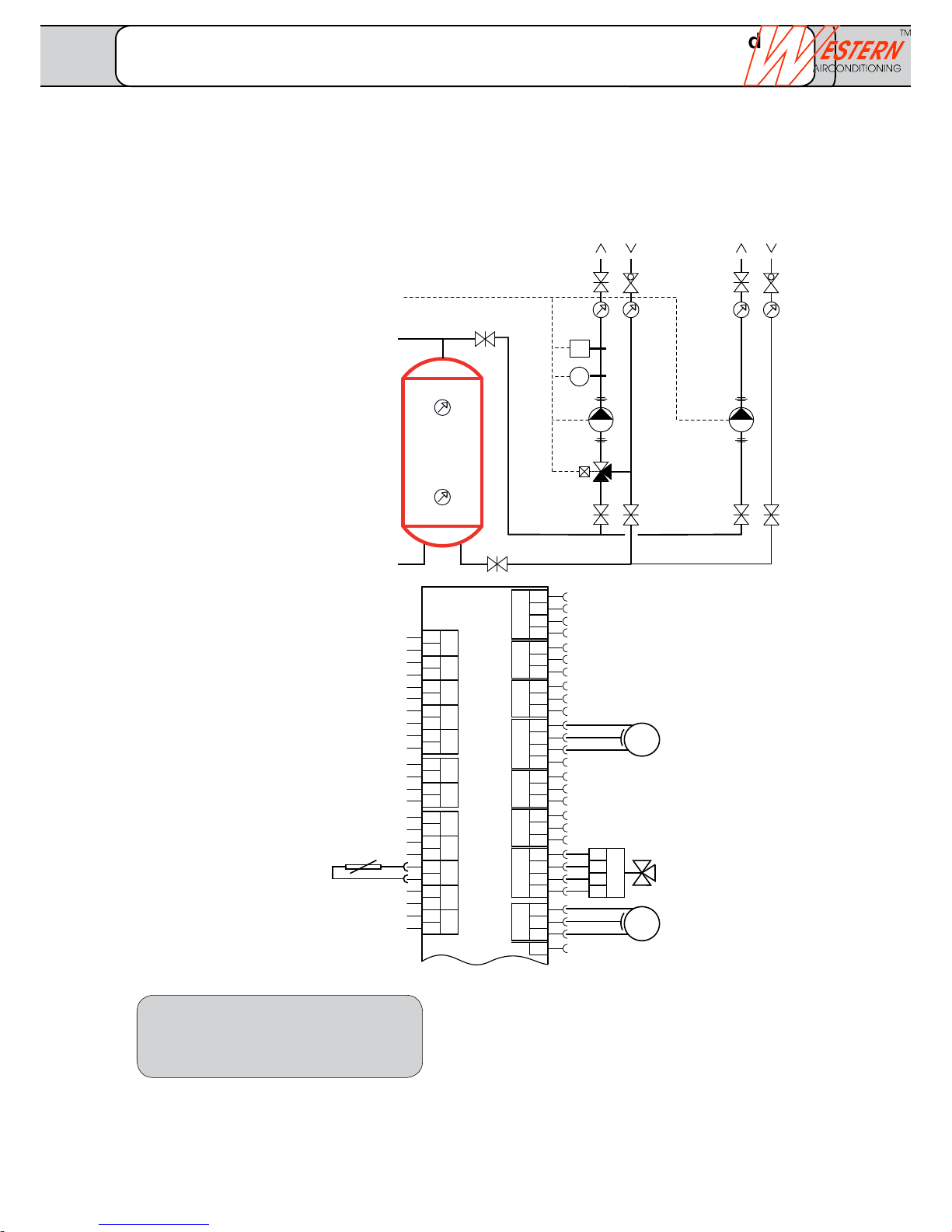
Legend
B1 Flow temperature sensor
Heating circuit 1
Q2 Circulation pump heating circuit 1
(mixed)
BV Balancing valve
Y1 Mixer heating circuit 1,230 V
QX2 Circulation pump, pump circuit
230 V / 400 V
ST Safety thermostat
Heat pump with buffer storage or combination storage
No extension module required!
Note: This additional sheet contains additional connection instructions for the electrical installation.
• Subjecttotechnicalchanges.
• Installationofadditionalcomponents
as per local regulations and conditions.
• Thispresentationisusedasplanningaidforthe
fitter.
Buffer storage
(or combination storage)
Heating circuit 1
with mixer
Consumer without
mixer
for controller
QX2 Circulation pump,
pump circuit 230 V,
max. 2.0 A
(or 400 V via ext.
power contactor)
Y1 Mixer heating circuit 1
230 V
Q2 Circulation pump heating
circuit 1 230 V, max.
1.0 A (or 400 V via ext.
power contactor)
Opt: Safety thermo stat (ST) in series with Q2
B1 Flow
Temperature sensor HK1
Extensions
Controller Optiplus (RVS 61/3)
Extension 1: Heating circuit 1 mixed and consumer unmixed
FUSIO W with controller Optiplus
_______________________________________________________________________________
Western Airconditioning B.V. reserves the right to alter specifications
Page 25
Y1
Q2
B1
ST
QX21
QX23
BX21
QX22
T
QX23
QX21
N
PE
L
n
M
H2
M
BX22
M
BX21
n
n
S
PE
N
PE
N
N
PE
L
Erweiterungsmodul
AVS75.390
2
T
4
3
3
2
S
N
PE
L
n
2
n
2
n
2
X50
Zu
Auf
PE
N
M
1~
L
PE
N
SRV SRV
ST
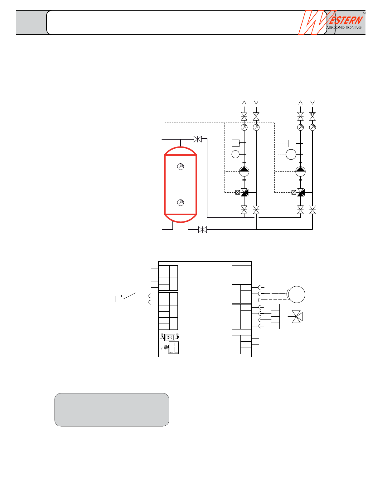
Legend
B1 Flow temperature sensor heating
circuit 1
Q2 Circulation pump heating circuit 1
Connection as per base sheet for
basic concept and HP type
BV Balancing valve
Y1 Mixer heating circuit 1,230 V
BX21 Flow temperature sensor heating
circuit 2
BX22 Slot empty
QX23 Circulation pump heating circuit 2
230 V, max 2 Amp.
QX21 Mixer heating circuit 2, 230 V
ST Safety thermostat
H2 Digital input
X50 Flat plug for connection
Connection cable for
controller-basic module
Note:
Parameterisation in the heating circuit 2 is done in the
parameter points 1010-1151, which appear for the
connection of the extension module. No additional
software required!
Heat pump with buffer storage or combination storage
Required additionally: Extension module AVS 75.390
Note: This additional sheet contains additional connection instructions for the electrical installation.
• Subjecttotechnicalchanges.
• Installationofadditionalcomponents
as per local regulations and conditions.
• Thispresentationisusedasplanningaidforthe
fitter.
Buffer storage
(or combination storage)
Heating
circuit 1
Heating circuit 2
for controller
QX23 Circulation pump heating
circuit 2 230 V, max. 2.0 A
Opt: Safety thermostat
(ST) in series with Q23
QX21 Mixer heating circuit 2
Connection control voltage
Extension module
ABS75.390
Extension 2: 2 heating circuits mixed
FUSIO W with controller Optiplus
_______________________________________________________________________________
Western Airconditioning B.V. reserves the right to alter specifications
Page 26
climate
cold heat
Q3
B3
K6
SV
TS
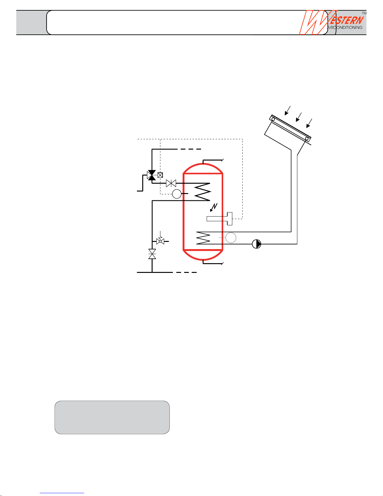
DHW heating with hydraulic switchover
Additional: Solar charging with independent solar system
• Subjecttotechnicalchanges.
• Installationofadditionalcomponents
as per local regulations and conditions.
• Thispresentationisusedasplanningaidforthe
fitter.
Charging circuit DHW Domestic hot water
storage tank
Solar system
(control independent of
heat pump)
Connection diagram for heat
pump and hydraulic integration
as well as legends:
as per basic concept
Terminal assignment:
as per basic concept
DHW heating with electric heating
insert
DHW heating solar (additional)
TS Solar sensor
DHW
CW
Extension 3: Hot water storage tank with solar circuit
FUSIO W with controller Optiplus
_______________________________________________________________________________
Western Airconditioning B.V. reserves the right to alter specifications
Page 27
QX4
PE
N
QX2
QX1
Q9
Q8
W
V
U
QX3
Y2
Y1
T
Q2
S
Q3
R
w
M
M
M
BX1
M
M
B91
M
B71
M
B1
M
B21
M
B9
M
B3
M
B81
u
t
s
r
q
p
n
k
h
f
X
Y
K1
Q
PE
N
PE
N
PE
N
PE
N
PE
N
PE
N
PE
N
Wärmepumpenregler (RVS 61/3)
3
2
U
3
2
V
2
W
4
3
3
3
2
X
2
Y
2
T
4
3
2
Z
4
3
3
2
S
3
2
R
2
Q
w
2
u
2
t
2
z
2
y
2
x
2
s
2
r
2
q
2
p
2
n
2
k
2
h
2
f
2
3
e
2
BX3
BX2
B92
PE
QX6
QX5
N
Z
x
y
z
M
BX4
M
M
UX2
UX1
H3
M
H1
e
M
1~
L
PE
N
SWP
Q15
B13
RSV
Y1
Q2
B1
ST
SRV
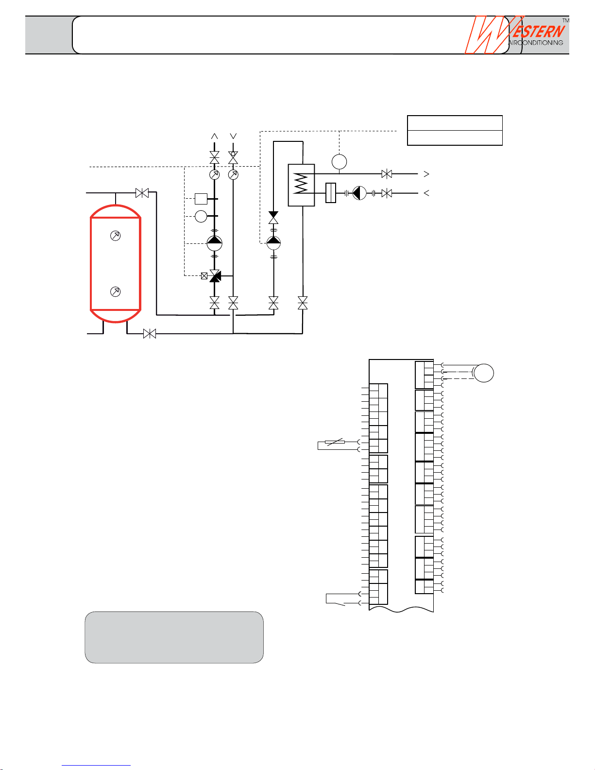
Heat pump with swimming pool charging
Note: This additional sheet contains additional connection instructions for the electrical installation.
Legend
B13 Swimming pool sensor
(Limit Tmax.)
Q15 Swimming pool circulation pump/
Deflector valve
H1 enabled externally
NRV Non-return valve
SWP Swimming pool pump
(controlled externally)
Function description
As soon as the swimming pool pump is put into operation,
the heat pump for the swimming pool charging is
switched-on from outside by the swimming pool controller
via input H1.
The swimming pool pump is controlled by the swimming
pool controller.
The swimming pool temperature (control temperature) is
monitored with the swimming pool sensor (B13).
Attention:
The heat pump must not be enabled unless there is a flow
through the heat exchanger.
When operating the swimming pool charging with/without
buffer storage, the total heat pump output (B0/W35 or
W10/W35) must be accepted by the swimming pool heat
exchanger.
The swimming pool must be taken into consideration when
designing the soil sensor.
• Subjecttotechnicalchanges.
• Installationofadditionalcomponents
as per local regulations and conditions.
• Thispresentationisusedasplanningaidforthe
fitter.
Buffer storage
(or combination storage)
Heating circuit 1 Swimming pool charging
for controller
Swimming pool
Swimming pool controller
Enabled on H1 contact
H1 enabled externally
Swimming pool charging
(floating (gold-)contact)
BX2 Swimming pool sensor B13
QX6 Swimming pool -
circulation pump (Q15)
230 V, max. 2.0 A
Heat pump controller (RVS 61/3)
with controller OptiplusExtension 4:
FUSIO W Swimming pool heater
_______________________________________________________________________________
Western Airconditioning B.V. reserves the right to alter specifications
Page 28
climate
cold heat
QX4
PE
N
QX2
QX
Q9
Q8
W
V
U
QX3
Y2
T
w
M
M
M
BX1
M
M
B91
M
B71
M
B1
u
t
s
r
q
p
X
Y
PE
N
PE
N
PE
N
PE
N
PE
N
Regler Optiplus (RVS 61/3)
3
2
U
3
2
V
2
W
4
3
3
3
2
X
2
Y
2
T
4
3
2
Z
4
3
w
2
u
2
t
2
z
2
y
2
x
2
s
2
r
2
q
2
p
2
BX3
BX2
B92
PE
QX6
QX5
N
Z
x
y
z
M
BX4
M
M
UX2
UX1
Y1
L
L
L
PE
N
Y 21
Zu
Auf
PE
N
Y1 / Y2
N1
B9
Y1/Y2
B1
Y21
PWT
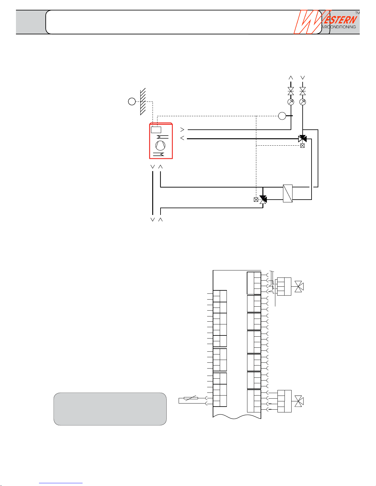
Free cooling, heating circuit/cooling circuit directly without buffer storage
Note: This additional sheet contains additional connection instructions for the electrical installation.
Function description
For passive cooling (free cooling), cooling is done
without operating the cryogenic unit. Heat is directly
returned to the connected source (soil sensor or
ground water).
The heat pump controller runs a cooling curve via the
ambient temperature (B9), this is controlled with the
connected mixer (Y1/Y2) and the flow temperature
(B1). For cooling requirement, the source circuit is
controlled by means of a deflector valve (Y21) via the
plate heat exchanger (PHE). For heating requirement,
the deflector valve is reset and the mixer is shut.
For available room thermostat valves, these must
be adaptable for the cooling as well as the
heating operation.
• Subjecttotechnicalchanges.
• Installationofadditionalcomponents
as per local regulations and conditions.
• Thispresentationisusedasplanningaidforthe
fitter.
Heat pump with basic concept
GK 01. ... (brine/water)
GK 04 ...(water/water)
Consumer
Heating circuit/ cooling circuit
Circulation via
Condenser pump
Source circuit
Connection for heat pump
Source connection
Soil sensor or ground water
Y1/Y2 Mixing valve for free cooling
230 V, max. 2.0 A
B1 Flow temperature sensor
additionally allocated terminals Connection
Enabled
Free cooling
Y21 Deflector valve free cooling
230 V, max. 2.0 A
Legend
B1 Flow temperature sensor
Cooling circuit
B9 External temperature sensor
N1 Heat pump controller
Optiplus (built-in)
PHE Plate heat exchanger
(for cooling)
Q8/Q9 Integrated circulation pump
Y1/Y2 Mixer for cooling circuit 230 V
Y21 Deflector valve 230 V
Extension 5: Free cooling for GK 01. ... or GK 04. ...
Optiheat OH es with controller Optiplus
_______________________________________________________________________________
Western Airconditioning B.V. reserves the right to alter specifications
Page 29
N1
B9
Y21
Q2
Y1/Y2
B1
Y21
PWT
QX4
PE
N
QX2
QX
Q9
Q8
W
V
U
QX3
Y2
T
w
M
M
M
BX1
M
M
B91
M
B71
M
B1
u
t
s
r
q
p
X
Y
PE
N
PE
N
PE
N
PE
N
PE
N
Regler Optiplus (RVS 61/3)
3
2
U
3
2
V
2
W
4
3
3
3
2
X
2
Y
2
T
4
3
2
Z
4
3
w
2
u
2
t
2
z
2
y
2
x
2
s
2
r
2
q
2
p
2
BX3
BX2
B92
PE
QX6
QX5
N
Z
x
y
z
M
BX4
M
M
UX2
UX1
Y1
L
L
L
PE
N
Y 21
Zu
Auf
PE
N
Y1 / Y2
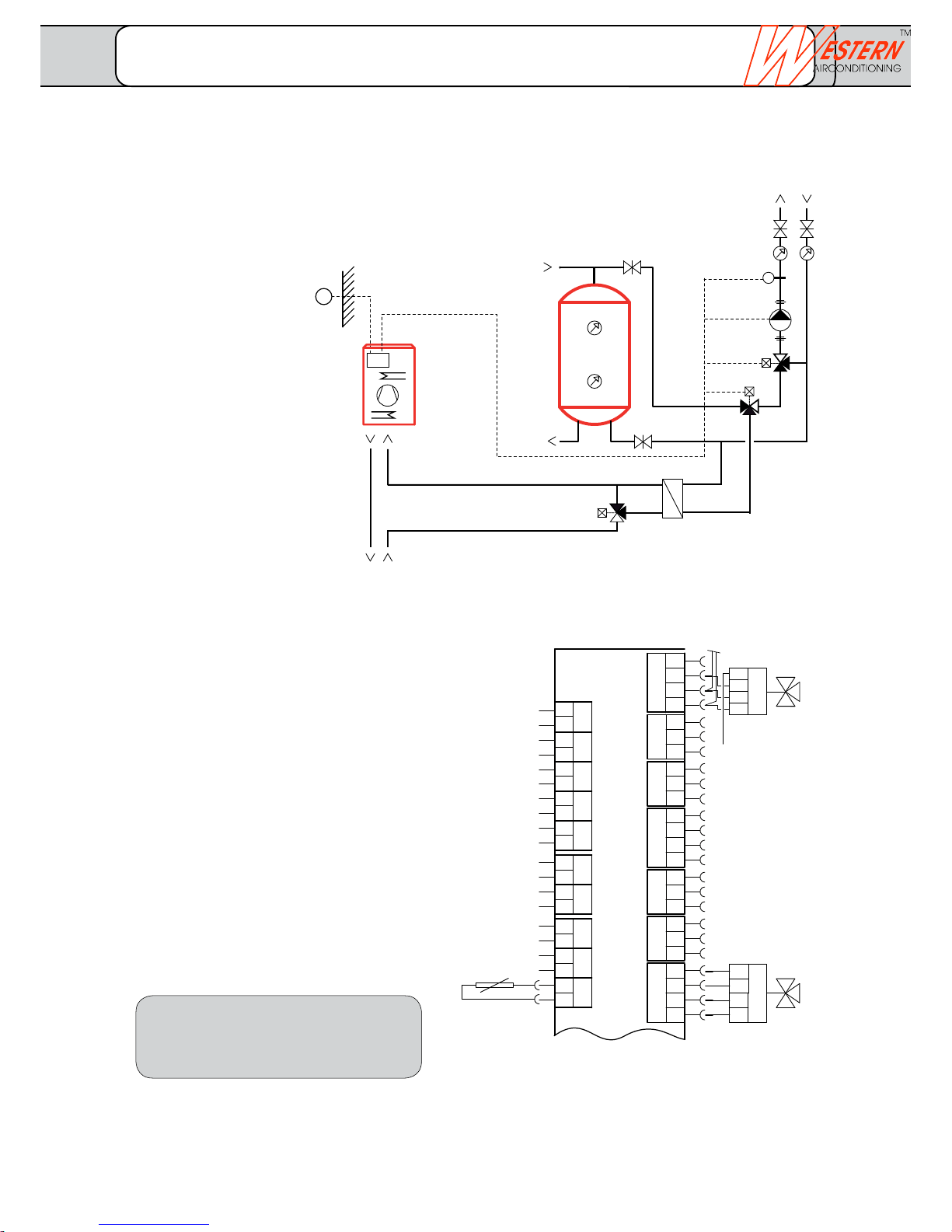
Free cooling, heating circuit/cooling circuit indirectly with buffer storage or combination storage
Note: This additional sheet contains additional connection instructions for the electrical installation.
Function description
For passive cooling (free cooling), cooling is done
without operating the cryogenic unit. Heat is directly
returned to the connected source (soil sensor or
ground water).
The heat pump controller runs a cooling curve via the
ambient temperature (B9), this is controlled with the
connected mixer (Y1/Y2) and the flow temperature
(B1). For cooling requirement, the source circuit is
controlled by means of a deflector valve (Y21) on both
sides via the plate heat exchanger (PHE).
For heating requirement, the deflector valve is set back
to the heating position. For a set discharge circuit
control, the mixing valve Y1/Y2 is integrated in the
controller.
For available room thermostat valves, these must be
adaptable for the cooling as well as the heating
operation.
Legend
B1 Flow temperature sensor
cooling circuit
B9 External temperature sensor
N1 Heat pump controller Opti
plus (built-in)
PHE Plate heat exchanger
(for cooling)
Q2 Heating circuit pump
Y1/Y2 Mixer for cooling circuit 230 V
Y21 Deflector valve 230 V
• Subjecttotechnicalchanges.
• Installationofadditionalcomponents
as per local regulations and conditions.
• Thispresentationisusedasplanningaidforthe
fitter.
Heat pump with basic concept
GK 02. ... (brine/water)
GK 05 ...(water/water)
Consumer
Buffer- or
Combination storage
Source circuit
Connection for heat pump
Source connection
Soil sensor or ground water
additionally allocated terminals
Connection
Enabled
Free cooling
Y1/Y2 Mixing valve for free cooling
230 V, max. 2.0 A
B1 Flow temperature sensor
Y21 Deflector valve free cooling
230 V, max. 2.0 A
Extension 6: Free cooling for GK 02. ... or GK 05. ...
FUSIO W with controller Optiplus
_______________________________________________________________________________
Western Airconditioning B.V. reserves the right to alter specifications
Page 30
climate
cold heat
B9
B4
B41
B10
PI
SV
EG
B92
B71
B91
N1
B21
Q9
SRV
M
Opt.
B92
B71
B91
N1
B21
Q9
SRV
M
Opt.
B92
B71
B91
N1
B21
Q9
SRV
M
Opt.
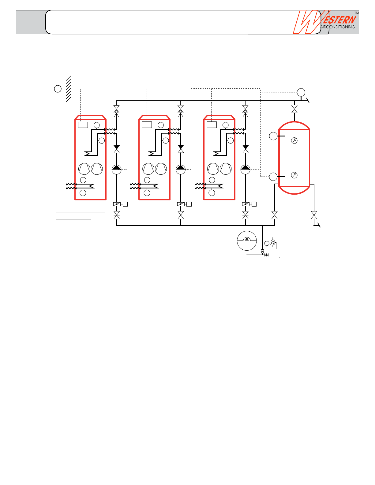
Legend
B10 Common flow sensor
B21 Flow temperature sensor, heat pump
B4 Buffer storage temperature sensor top
B41 Buffers storage temperature sensor bottom
B71 Return flow temperature sensor, heat
pump
B9 External temperature sensor
B91 Brine inlet temperature sensor
B92 Brine outlet temperature sensor
EV Expansion vessel
N1 Heat pump controller Optiplus built-in
PI Pressure gauge
Q9 Condenser pump
BV Balancing valve
Opt. el. butterfly valve (optional)
Requirement bus cable:
Cu cable 1.5 mm2. 2. Wire cannot be interchanged
with controller-bus power supply
(per controller) 250 m
with central bus power supply 460 m
Bus load rate E = 3
Function description
The heat pumps are operated via the external sensor B9. This
works on the buffer storage.
Depending upon the ambient temperature, the heat pumps
are switched on and off via the
temperature sensor B4 or B41. The machine has a starting
delay in order to prevent wobbling.
If the common flow temperature B10 is not attained, based on
release limit, another heat producer is switched on
additionally.
If the currently switched on heat producer exceeds the
requested power requirement, the producer switches off with
the highest priority.
System-specific testing/adaptation:
- Primary side (brine, water intake), discharge circuit control
- Storage size depending upon the performance of the heat
producer
- Hydraulic integration
- Shut-off devices, control valves, check valves as per
requirement
- Design of expansion system
- Fit adequate dipping sleeves for sensors, thermostats
and thermometer
- Observe structural conditions (insertion, installation, ...)
Cascade operation with several heat pumps with buffer storage
Heat pump 1
Master
Heat pump 2
Slave
Heat pump 3
Slave
Buffer storage
Detail description of
Primary circuit
as per basic concept
Extension 7: Cascade
FUSIO W with controller Optiplus
_______________________________________________________________________________
Western Airconditioning B.V. reserves the right to alter specifications
Page 31
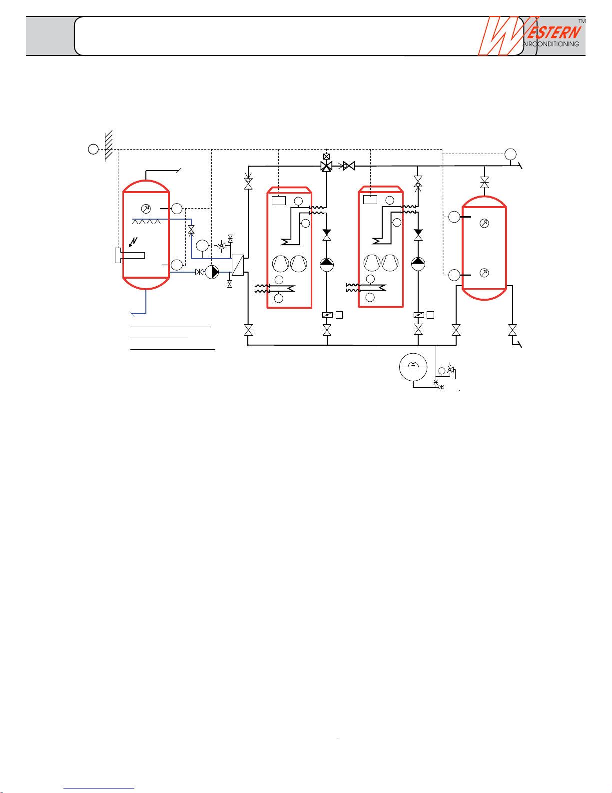
B9
B4
B41
B10
B92
B71
B91
N1
B21
Q9
SRV
B92
B71
B91
N1
B21
Q9
SRV
PI
SV
EG
SV
Q33
B36
TWW
B3
B31
K6
KW
Q3
M
Opt.
M
Opt.
SRV
SRV
Legend
B10 Common flow sensor
B21 Flow temperature sensor, heat pump
B3 Domestic water sensor top
B31 Domestic water sensor bottom
B36 Domestic water charging sensor
B4 Buffer storage temperature sensor top
B41 Buffers storage temperature sensor
bottom
B71 Return flow temperature sensor, heat
pump
B9 External temperature sensor
B91 Brine inlet temperature sensor
B92 Brine outlet temperature sensor
EV Expansion vessel
K6 Electric heating insert
N1 Heat pump controller Optiplus built-in
PI Pressure gauge
Q3 Domestic water - deflector valve
Q33 Domestic water - intermediate circuit
pump
Q9 Condenser pump
BV Balancing valve
Opt. el. butterfly valve (optional)
Requirement bus cable:
Cu cable 1.5 mm2, 2. Wire cannot be interchanged
with controller-bus power supply
(per controller) 250 m
with central bus power supply 460 m
Bus load rate E = 3
Function description
The first slave machine is used for warm water charging,
wherein, even the appropriate components are connected. At
active charging, the heat pump is isolated hydraulically from
the system and is not available for the heating operation.
After complete charging, the heat pump is again available for
the heating operation.
The control regulates the domestic water temperature as per
time schedule program at the desired setpoint. Boiler charging
is started via drinking water sensor (B3). Once the sensor
(B31) attains the desired temperature, charging is stopped.
System-specific testing/adaptation:
- Primary side (brine, water intake), discharge circuit control
- Storage size depending upon the performance of the heat
producer
- Hydraulic integration
- Shut-off devices, control valves, check valves as per
requirement
- Design of expansion system
- Fit adequate dipping sleeves for sensors, thermostats
and thermometer
- Observe structural conditions (insertion, installation, ...)
Cascade operation with several heat pumps with buffer storage and DHW charging
with hydraulic switchover
Detail description of
Primary circuit
as per basic concept
Heat pump 1
Slave 1
Heat pump 2
Master
Hot water
storage tank
Buffer storageCharging circuit
DHW
Extension 7: Cascade with DHW
FUSIO W with controller Optiplus
_______________________________________________________________________________
Western Airconditioning B.V. reserves the right to alter specifications
Page 32
climate
cold heat
Y1
Q2
B1
ST
B9
Y2
Y1
N
Q2
N
N
L
060706A
000020RVS46.530/109
1PRVS46.530/109
S060706000020
SRV
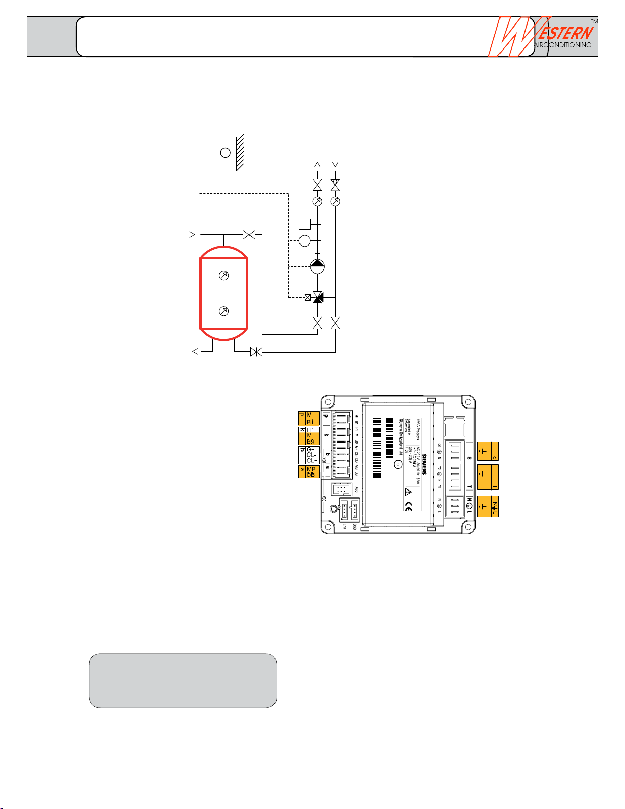
1 consumer circuit controlled
Note: This additional sheet contains additional connection instructions for the electrical installation.
• Subjecttotechnicalchanges.
• Installationofadditionalcomponents
as per local regulations and conditions.
• Thispresentationisusedasplanningaidforthe
fitter.
Buffer storage
(or combination storage)
Heating circuit 1
with mixer
Flow HK1
Input H1
External sensor
Opt. Illumination
RG1
LPB
HK1 pump
HK1mixer
Supply
for controller
Legend
B1 Flow temperature sensor heating circuit 1
B9 External sensor (optional)
Q2 Circulation pump heating circuit 1
BV Balancing valve
ST Safety thermostat
Y1 Mixer heating circuit 230 V
LPB Connection to main controller
Requirement bus cable:
Cu cable 1.5 mm
2
, 2. Wire cannot be interchanged
with controller-bus power supply
(per controller) 250 m
with central bus power supply 460 m
Bus load rate E = 3
Extension 20: Heating circuit mixed
FUSIO W... with slave controller RVS 46.530
_______________________________________________________________________________
Western Airconditioning B.V. reserves the right to alter specifications
Page 33
Y1
Q2
B1
ST
QX1
B9
SRV
SRV
060404A
000020RVS46.543/109
1PRVS46.543/109
S060404000020
b
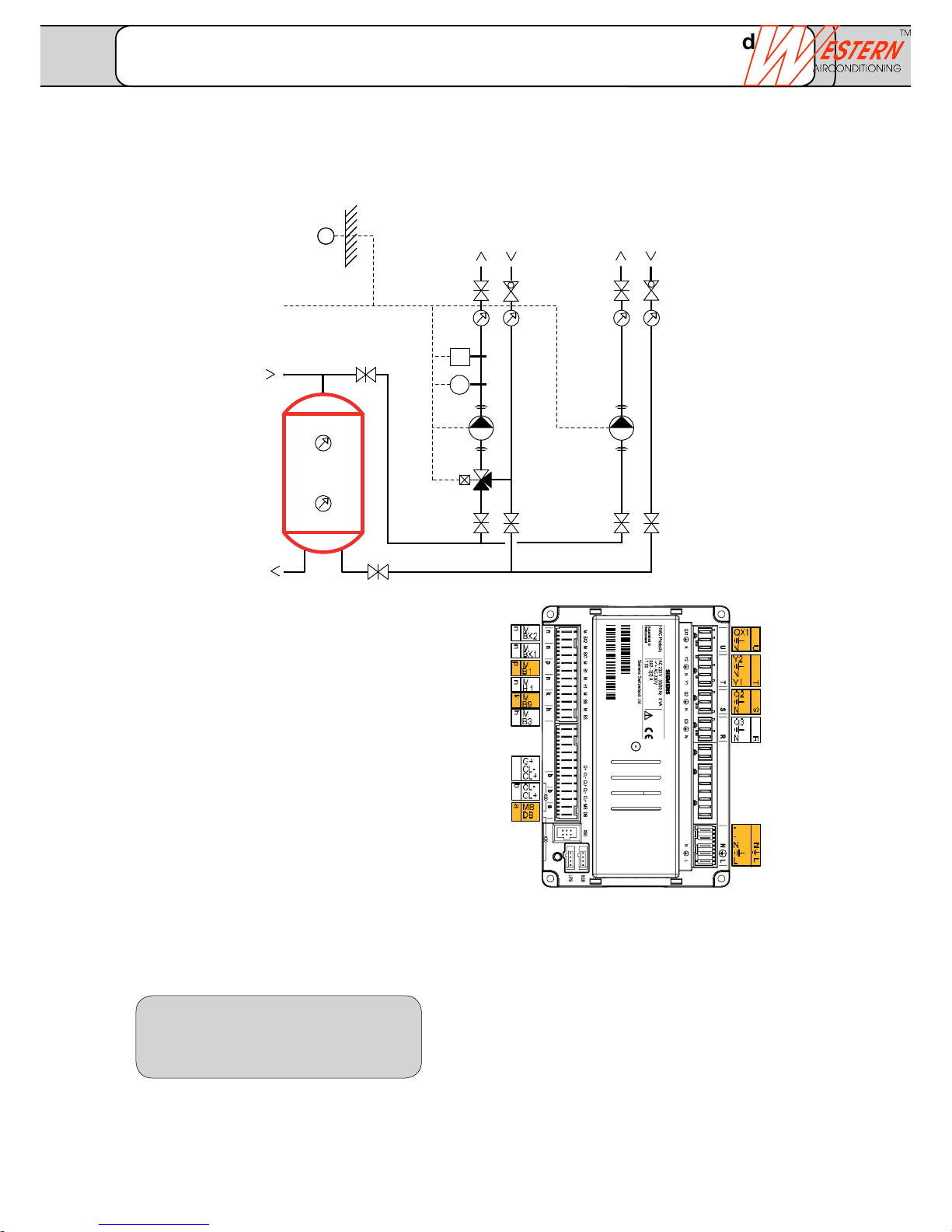
2 consumer circuits, controls a group
Note: This additional sheet contains additional connection instructions for the electrical installation.
Legend
B1 Flow temperature sensor heating
circuit 1
B9 External sensor (optional)
Q2 Circulation pump heating circuit 1
(mixed)
QX1 Circulation pump HKP
BV Balancing valve
ST Safety thermostat
Y1 Heating circuit mixer 230V
LPB Connection to main controller
Requirement bus cable:
Cu cable 1.5 mm2. 2. Wire cannot be
interchanged
with controller-bus power supply
(per controller) 250 m
with central bus power supply 460 m
Bus load rate E = 3
• Subjecttotechnicalchanges.
• Installationofadditionalcomponents
as per local regulations and conditions.
• Thispresentationisusedasplanningaidforthe
fitter.
Cooling agent fluid B83
Hot gas sensor 2 B82
Flow HK1
Input H1
External sensor
Domestic hot water top
HKP - pump
HK1- mixer
HK1- pump
DHW valve
Opt. Illumination
RG1 / RG2
RG1 / RG2
LPB
Supply
Buffer storage
(or combination storage)
Heating circuit 1
with mixer
Consumer
without mixer
Extension 21: Heating circuit mixed and consumer unmixed
FUSIO W... with slave controller RVS 46.543
_______________________________________________________________________________
Western Airconditioning B.V. reserves the right to alter specifications
Page 34
climate
cold heat
060404A
000020RVS46.543/109
1PRVS46.543/109
S060404000020
b
.
.
Y1
Q2
B1
ST
Q3
KW
TWW
B3
K6
SV
B9
SRV
SRV
M
Opt.
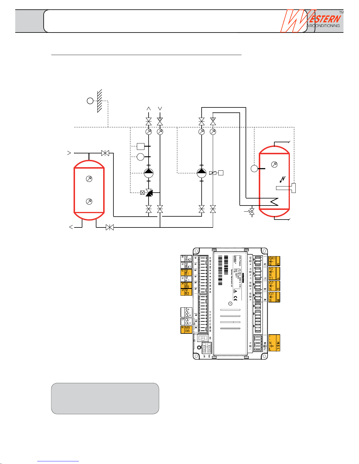
Consumer circuit mixed and DHW heating with charging pump
No speed control of the charging pump Q3 possible with slave controller
Note: This additional sheet contains additional connection instructions for the electrical installation.
Legend
B1 Flow temperature sensor heating
circuit 1
B3 Domestic hot water top
B9 External sensor (optional)
K6 Electrical heating insert DHW
Q2 Circulation pump heating circuit 1
Q3 DHW - charging pump
BV Balancing valve
ST Safety thermostat
Y1 Heating circuit mixer 230V
LPB Connection to main controller
Opt. el. butterfly valve (optional)
Requirement bus cable:
Cu cable 1.5 mm
2
, 2. Wire cannot be
interchanged
with controller-bus power supply
(per controller) 250 m
with central bus power supply 460 m
Bus load rate E = 3
• Subjecttotechnicalchanges.
• Installationofadditionalcomponents
as per local regulations and conditions.
• Thispresentationisusedasplanningaidforthe
fitter.
Buffer storage
(or combination storage)
Heating circuit 1
with mixer
for controller
DHW charging
Flow HK1
Input H1
External sensor
Domestic hot water top
Electrical insert K6
HK1- mixer
HK1- pump
DHW valve Q3
Opt. Illumination
RG1 / RG2
RG1 / RG2
LPB
Supply
Extension 22: Heating circuit mixed and DHW heating
FUSIO W... with slave controller RVS 46.543
_______________________________________________________________________________
Western Airconditioning B.V. reserves the right to alter specifications
Page 35
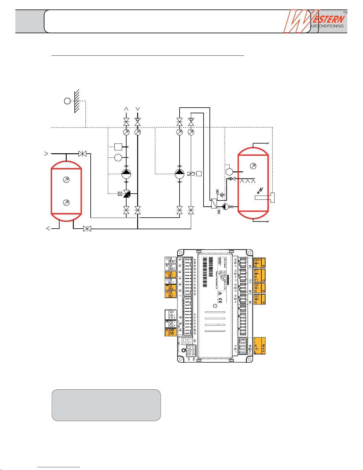
060404A
000020RVS46.543/109
1PRVS46.543/109
S060404000020
b
Y1
Q2
B1
ST
Q3
B9
B3
SV
Q33
KW
TWW
K6
SRV
SRV
M
Opt.
Consumer circuit mixed and DHW heating with charging pump and external heat exchanger
No speed control of the charging pump Q3 possible with slave controller
Note: This additional sheet contains additional connection instructions for the electrical installation.
Legend
B1 Flow temperature sensor heating
circuit 1
B3 Domestic hot water top
B9 External sensor (optional)
K6 Electrical heating insert DHW
Q2 Circulation pump heating
circuit 1
Q3 DHW charging pump
Q33 DHW- intermediate circuit pump
BV Balancing valve
ST Safety thermostat
Y1 Heating circuit mixer 230 V
LPB Connection to main controller
Opt. el. butterfly valve (optional)
Requirement bus cable:
Cu cable 1.5 mm
2
, 2. Wire cannot be
interchanged
with controller-bus power supply
(per controller) 250 m
with central bus power supply 460 m
Bus load rate E = 3
• Subjecttotechnicalchanges.
• Installationofadditionalcomponents
as per local regulations and conditions.
• Thispresentationisusedasplanningaidforthe
fitter.
for controller
Flow HK1
Input H1
External sensor
Domestic water
top
Electrical insert K6
HK1- mixer
HK1- pump
DHW pumps (Q3
and Q33)
Opt. Illumination
RG1 / RG2
RG1 / RG2
LPB
Supply
Buffer storage
(or combination storage)
Heating circuit 1
with mixer
DHW charging
Extension 23: Heating circuit mixed and DHW heating
FUSIO W... with slave controller RVS 46.543
_______________________________________________________________________________
Western Airconditioning B.V. reserves the right to alter specifications
Page 36
climate
cold heat
6 kW 3 kW
32241
6
110K6
2 4 6
14
3 2 1
L1
L2
L3
N
PE
QX4
PE
N
QX2
QX1
Q9
Q8
L3
N
N
L
L
EM
W
V
U
3
2
1
QX3
Y2
Y1
T
Q2
S
Q3
R
Ex7
EX6
EX5
EX4
EX3
EX2
EX1
N
PE
L
w
M
M
M
BX1
M
M
B91
M
B71
M
B1
M
B21
M
B9
M
B3
M
B81
G+
CL-
CL+
u
t
s
r
q
p
n
k
h
b
b
f
b
X
Y
K1
E11
Q
P
E10
E9
K
PE
N
PE
N
PE
N
PE
N
PE
N
PE
N
PE
N
CL-
CL+
CL-
CL+
N
PE
L
PE
L1
L2
X60
X30
BSB
3
2
U
3
2
V
2
W
4
3
3
3
2
X
2
Y
2
T
4
3
2
Z
4
3
3
2
S
3
2
R
2
Q
7
6
5
4
3
2
2
P
K
N
PE
L
w
2
u
2
t
2
z
2
y
2
x
2
s
2
r
2
q
2
p
2
n
2
k
2
h
2
f
2
3
e
2
3
b
2
b
2
b
2
BX3
BX2
B92
14
a
MB
DB
a
2
PE
QX6
QX5
N
Z
x
y
z
M
BX4
M
M
UX2
UX1
H3
M
H1
e
UX1 Output 0 - 10 V
diverse functions
UX2 Output 0 - 10 V
diverse functions
BX4 Buffer storage
temperature sensor (B4)
BX3 DHW Temperature
sensor (B31)
BX2 Cooling agent temperature
sensor fluid (B83)
BX1 Hot gas temperature
sensor (B82)
B92 Source outlet
temperature sensor
B91 Source inlet
temperature sensor
B71 Return flow temperature sensor
Heat pump
B1 Flow temperature sensor
Heating circuit 1
B21 Flow temperature sensor
Heat pump
B9 External temperature sensor
B3 Domestic water temperature
sensor
B81 Hot gas temperature sensor
Compressor 1
H3 Digital 0..10 V input
H1 Digital 0..10 V input
BSB Room unit illumination
(optional)
QAA55 Phase 1 + 2
QAA75 Phase 1 - 3
BSB Connection for external
control units
BSB Connection for external
control units
LPB Connection (cascade, bivalence)
Heat pump controller Optiplus (RVS 61/3)
Fuse as per heat pump
type:
See separate sheet
Technical data
Attention:
The rotating field to the right is absolutely
necessary.
Local regulations must be followed.
Subject to technical changes.
Attention: Max. total reference current of all
230 V connections6 A
(max. 2 A per connection)
QX6 Alarm output (K10)
optional
QX5 Deflector valve free cooling (Y21)
QX4 Relay output 230 V
diverse functions
(modulated up to max. 1.4A)
QX3 Electric heating insert DHW (K6)
QX2 Pump (Q20)
QX1 Electric heating insert (K25)
(built-in)
Q9 Condenser pump
(built-in)
Q8 Brine pump (built-in)
(directly or via an internal power
contactor)
Y1 Heating circuit mixer 230 V
/Y2 (Y1 = open / Y2 = closed)
Q2 Heating circuit pump 230 V
Q3 Deflector valve DHW 230 V
K1 Compressor 1
E11 Overload compressor 1
Ex7 Three phase current T
Ex6 Three phase current S
Ex5 Three phase current R
Ex4 Thermal relay source pump
Ex3 Pressure / flow source (E15)
Ex2 EW lock (E6)
Ex1 Reduced rate (E5)
E10 High pressure HP
E9 Low pressure BP
Internal wiring not
illustrated!!
on-site tableau
EW lock
EW lock Contact is closed
when heat pump is enabled
Circuit breaker all-pole
Supply heat pump
Standard
Main
switch
installed
for HP
Terminal diagrams
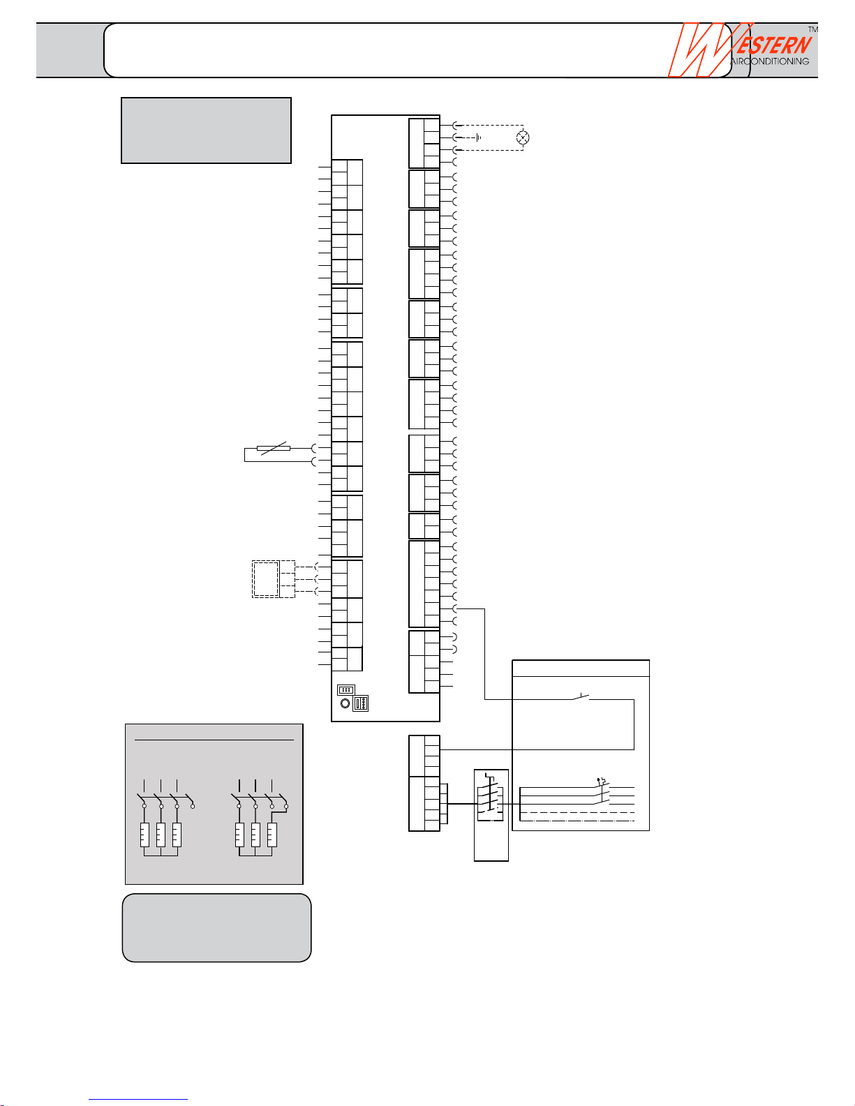
Terminal diagram for basic concept 01.00.10
FUSIO W 5 - FUSIO W 18
Connection electric heating insert K25 (internal)
FUSIO W 5 - FUSIO W 18
_______________________________________________________________________________
Western Airconditioning B.V. reserves the right to alter specifications
Page 37
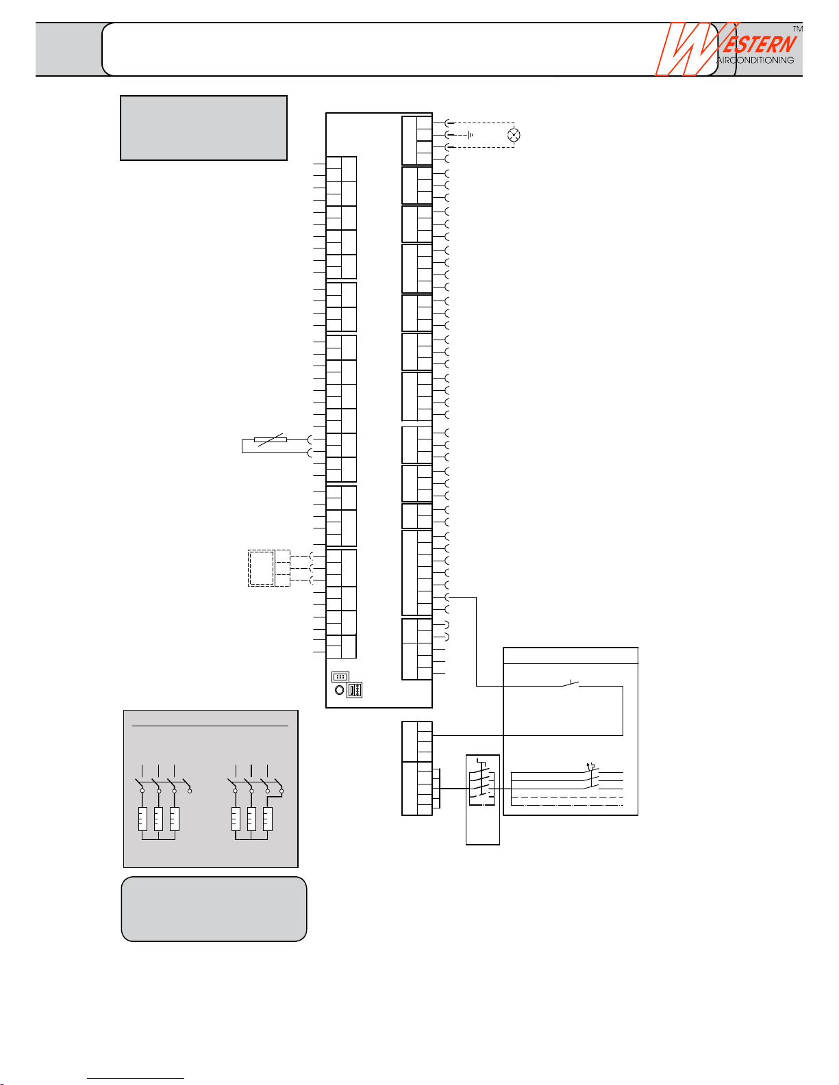
6 kW 3 kW
32241
6
110K6
2 4 6
14
3 2 1
L1
L2
L3
N
PE
QX4
PE
N
QX2
QX1
Q9
Q8
L3
N
N
L
L
EM
W
V
U
3
2
1
QX3
Y2
Y1
T
Q2
S
Q3
R
Ex7
EX6
EX5
EX4
EX3
EX2
EX1
N
PE
L
w
M
M
M
BX1
M
M
B91
M
B71
M
B1
M
B21
M
B9
M
B3
M
B81
G+
CL-
CL+
u
t
s
r
q
p
n
k
h
b
b
f
b
X
Y
K1
E11
Q
P
E10
E9
K
PE
N
PE
N
PE
N
PE
N
PE
N
PE
N
PE
N
CL-
CL+
CL-
CL+
N
PE
L
PE
L1
L2
X60
X30
BSB
3
2
U
3
2
V
2
W
4
3
3
3
2
X
2
Y
2
T
4
3
2
Z
4
3
3
2
S
3
2
R
2
Q
7
6
5
4
3
2
2
P
K
N
PE
L
w
2
u
2
t
2
z
2
y
2
x
2
s
2
r
2
q
2
p
2
n
2
k
2
h
2
f
2
3
e
2
3
b
2
b
2
b
2
BX3
BX2
B92
14
a
MB
DB
a
2
PE
QX6
QX5
N
Z
x
y
z
M
BX4
M
M
UX2
UX1
H3
M
H1
e
UX1 Output 0 - 10 V
diverse functions
UX2 Output 0 - 10 V
diverse functions
BX4 Buffer storage
temperature sensor (B4)
BX3 DHW Temperature
sensor (B31)
BX2 Cooling agent temperature
sensor fluid (B83)
BX1 Hot gas temperature
sensor (B82)
B92 Source outlet
temperature sensor
B91 Source inlet
temperature sensor
B71 Return flow temperature sensor
Heat pump
B1 Flow temperature sensor
Heating circuit 1
B21 Flow temperature sensor
Heat pump
B9 External temperature sensor
B3 Domestic water temperature
sensor
B81 Hot gas temperature sensor
Compressor 1
H3 Digital 0..10 V input
H1 Digital 0..10 V input
BSB Room unit illumination
(optional)
QAA55 Phase 1 + 2
QAA75 Phase 1 - 3
BSB Connection for external
control units
BSB Connection for external
control units
LPB Connection (cascade, bivalence)
Heat pump controller Optiplus (RVS 61/3)
Fuse as per heat pump
type:
See separate sheet
Technical data
Attention:
The rotating field to the right is absolutely
necessary.
Local regulations must be followed.
Subject to technical changes.
Attention: Max. total reference current of all
230 V connections6 A
(max. 2 A per connection)
QX6 Alarm output (K10)
optional
QX5 Deflector valve free cooling (Y21)
QX4 Relay output 230 V
diverse functions
(modulated up to max. 1.4A)
QX3 Electric heating insert DHW (K6)
QX2 Pump (Q20)
QX1 Electric heating insert (K25)
(built-in)
Q9 Condenser pump
(built-in)
Q8 Brine pump (built-in)
(directly or via an internal power
contactor)
Y1 Heating circuit mixer 230 V
/Y2 (Y1 = open / Y2 = closed)
Q2 Heating circuit pump 230 V
Q3 Deflector valve DHW 230 V
K1 Compressor 1
E11 Overload compressor 1
Ex7 Three phase current T
Ex6 Three phase current S
Ex5 Three phase current R
Ex4 Thermal relay source pump
Ex3 Pressure / flow source (E15)
Ex2 EW lock (E6)
Ex1 Reduced rate (E5)
E10 High pressure HP
E9 Low pressure BP
Internal wiring not
illustrated!!
on-site tableau
EW lock
EW lock Contact is closed
when heat pump is enabled
Circuit breaker all-pole
Supply heat pump
Standard
Main
switch
installed
for HP
Terminal diagram for basic concept 01/01/2010
FUSIO W 5 - FUSIO W 18
Connection electric heating insert K25 (internal)
FUSIO W 5 - FUSIO W 18
_______________________________________________________________________________
Western Airconditioning B.V. reserves the right to alter specifications
Page 38
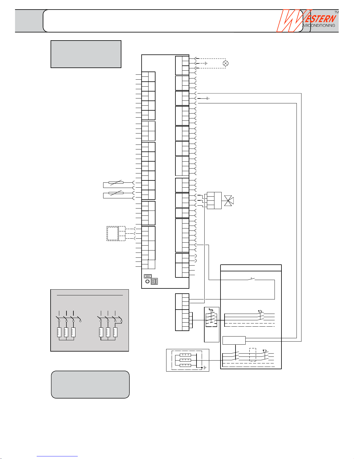
climate
cold heat
6 kW 3 kW
32241
6
110K6
2 4 6
14
3 2 1
L1
L2
L3
N
PE
QX4
PE
N
QX2
QX1
Q9
Q8
L3
N
N
L
L
EM
W
V
U
3
2
1
QX3
Y2
Y1
T
Q2
S
Q3
R
Ex7
EX6
EX5
EX4
EX3
EX2
EX1
N
PE
L
w
M
M
M
BX1
M
M
B91
M
B71
M
B1
M
B21
M
B9
M
B3
M
B81
G+
CLCL+
u
t
s
r
q
p
n
k
h
b
b
f
b
X
Y
K1
E11
Q
P
E10
E9
K
PE
N
PE
N
PE
N
PE
N
PE
N
PE
N
PE
N
CLCL+
CLCL+
N
PE
L
PE
L1
L2
X60
X30
BSB
3
2
U
3
2
V
2
W
4
3
3
3
2
X
2
Y
2
T
4
3
2
Z
4
3
3
2
S
3
2
R
2
Q
7
6
5
4
3
2
2
P
K
N
PE
L
w
2
u
2
t
2
z
2
y
2
x
2
s
2
r
2
q
2
p
2
n
2
k
2
h
2
f
2
3
e
2
3
b
2
b
2
b
2
BX3
BX2
B92
14
a
MB
DB
a
2
PE
QX6
QX5
N
Z
x
y
z
M
BX4
M
M
UX2
UX1
H3
M
H1
e
L
L
PE
N
L1
L2
L3
L1
L2
L3
N
PE
only up to 10 kW
additional protection for 12 and 15 kW
UX1 Output 0 - 10 V
diverse functions
UX2 Output 0 - 10 V
diverse functions
BX4 Buffer storage
temperature sensor (B4)
BX3 DHW Temperature
sensor (B31)
BX2 Cooling agent temperature
sensor fluid (B83)
BX1 Hot gas temperature
sensor (B82)
B92 Source outlet
temperature sensor
B91 Source inlet
temperature sensor
B71 Return flow temperature sensor
Heat pump
B1 Flow temperature sensor
Heating circuit 1
B21 Flow temperature sensor
Heat pump
B9 External temperature sensor
B3 Domestic water temperature
sensor
B81 Hot gas temperature sensor
Compressor 1
H3 Digital 0..10 V input
H1 Digital 0..10 V input
BSB Room unit illumination
(optional)
QAA55 Phase 1 + 2
QAA75 Phase 1 - 3
BSB Connection for external
control units
BSB Connection for external
control units
LPB Connection (cascade, bivalence)
Heat pump controller Optiplus (RVS 61/3)
Fuse as per heat pump
type:
See separate sheet
Technical data
Attention:
The rotating field to the right is absolutely
necessary.
Local regulations must be followed.
Subject to technical changes.
Attention: Max. total reference current of all
230 V connections6 A
(max. 2 A per connection)
QX6 Alarm output (K10)
optional
QX5 Deflector valve free cooling (Y21)
QX4 Relay output 230 V
diverse functions
(modulated up to max. 1.4A)
QX3 Electric heating insert DHW (K6)
QX2 Pump (Q20)
QX1 Electric heating insert (K25)
(built-in)
Q9 Condenser pump
(built-in)
Q8 Brine pump (built-in)
(directly or via an internal power
contactor)
Y1 Heating circuit mixer 230 V
/Y2 (Y1 = open / Y2 = closed)
Q2 Heating circuit pump 230 V
Q3 Deflector valve DHW 230 V
K1 Compressor 1
E11 Overload compressor 1
Ex7 Three phase current T
Ex6 Three phase current S
Ex5 Three phase current R
Ex4 Thermal relay source pump
Ex3 Pressure / flow source (E15)
Ex2 EW lock (E6)
Ex1 Reduced rate (E5)
E10 High pressure HP
E9 Low pressure BP
Internal wiring not
illustrated!!
on-site tableau
EW lock
EW lock: Contact is closed
when heat pump is enabled
Circuit breaker all-pole
Supply heat pump
Standard
Main
switch
installed
for HP
K6 Electric heating insert DHW
Enable contactor
manual/auto/off
e.g. Hager ET321 (507403200)
EW Boiler release (RSE)
Terminal diagram for basic concept 01.20.10
FUSIO W 5 - FUSIO W 18
Connection electric heating insert K25 (internal)
FUSIO W 5 - FUSIO W 18
_______________________________________________________________________________
Western Airconditioning B.V. reserves the right to alter specifications
Page 39
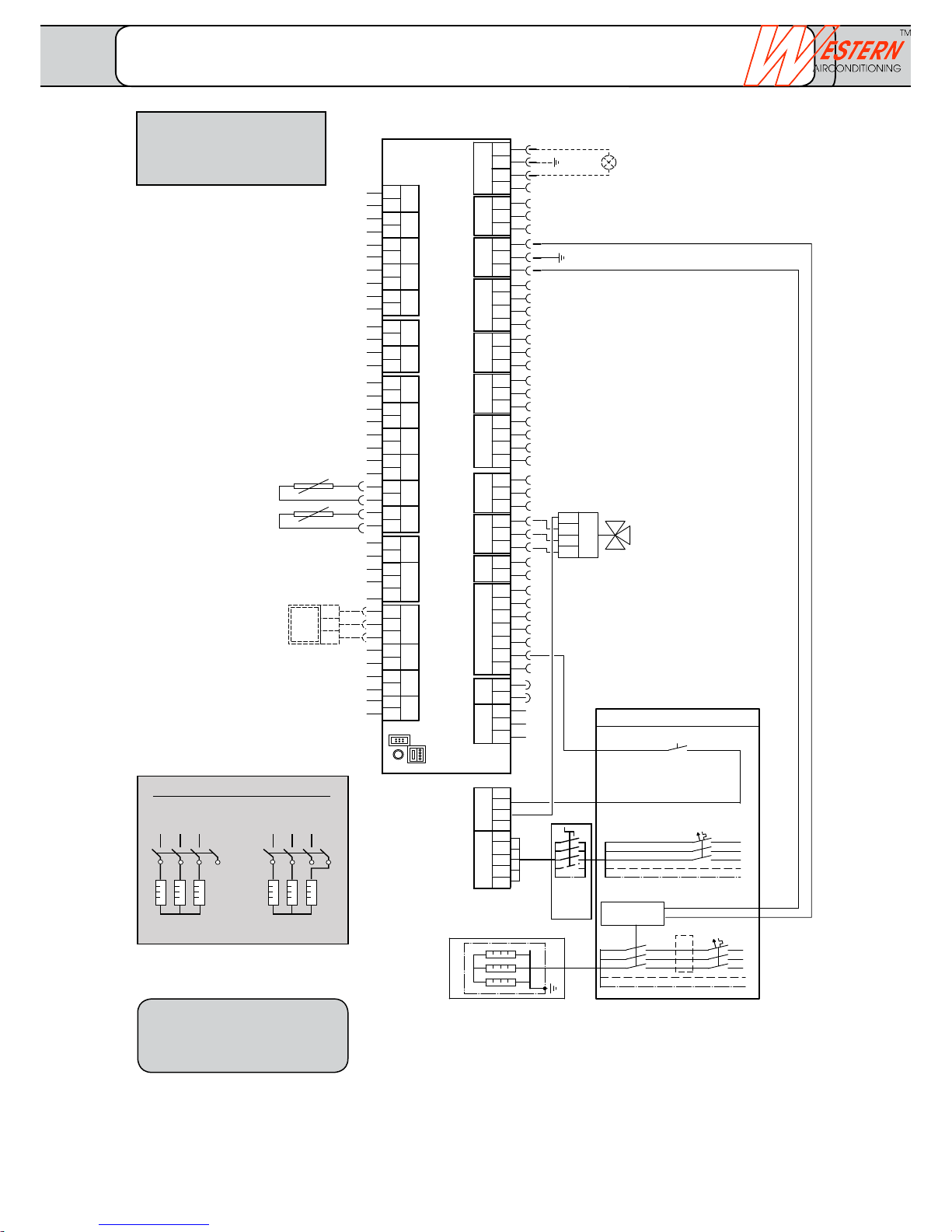
6 kW 3 kW
32241
6
110K6
2 4 6
14
3 2 1
L1
L2
L3
N
PE
QX4
PE
N
QX2
QX1
Q9
Q8
L3
N
N
L
L
EM
W
V
U
3
2
1
QX3
Y2
Y1
T
Q2
S
Q3
R
Ex7
EX6
EX5
EX4
EX3
EX2
EX1
N
PE
L
w
M
M
M
BX1
M
M
B91
M
B71
M
B1
M
B21
M
B9
M
B3
M
B81
G+
CL-
CL+
u
t
s
r
q
p
n
k
h
b
b
f
b
X
Y
K1
E11
Q
P
E10
E9
K
PE
N
PE
N
PE
N
PE
N
PE
N
PE
N
PE
N
CL-
CL+
CL-
CL+
N
PE
L
PE
L1
L2
X60
X30
BSB
3
2
U
3
2
V
2
W
4
3
3
3
2
X
2
Y
2
T
4
3
2
Z
4
3
3
2
S
3
2
R
2
Q
7
6
5
4
3
2
2
P
K
N
PE
L
w
2
u
2
t
2
z
2
y
2
x
2
s
2
r
2
q
2
p
2
n
2
k
2
h
2
f
2
3
e
2
3
b
2
b
2
b
2
BX3
BX2
B92
14
a
MB
DB
a
2
PE
QX6
QX5
N
Z
x
y
z
M
BX4
M
M
UX2
UX1
H3
M
H1
e
L
L
PE
N
L1
L2
L3
L1
L2
L3
N
PE
only up to 10 kW
additional protection for 12 and 15 kW
UX1 Output 0 - 10 V
diverse functions
UX2 Output 0 - 10 V
diverse functions
BX4 Buffer storage
temperature sensor (B4)
BX3 DHW Temperature
sensor (B31)
BX2 Cooling agent temperature
sensor fluid (B83)
BX1 Hot gas temperature
sensor (B82)
B92 Source outlet
temperature sensor
B91 Source inlet
temperature sensor
B71 Return flow temperature sensor
Heat pump
B1 Flow temperature sensor
Heating circuit 1
B21 Flow temperature sensor
Heat pump
B9 External temperature sensor
B3 Domestic water temperature
sensor
B81 Hot gas temperature sensor
Compressor 1
H3 Digital 0..10 V input
H1 Digital 0..10 V input
BSB Room unit illumination
(optional)
QAA55 Phase 1 + 2
QAA75 Phase 1 - 3
BSB Connection for external
control units
BSB Connection for external
control units
LPB Connection (cascade, bivalence)
Heat pump controller Optiplus (RVS 61/3)
Fuse as per heat pump
type:
See separate sheet
Technical data
Attention:
The rotating field to the right is absolutely
necessary.
Local regulations must be followed.
Subject to technical changes.
Attention: Max. total reference current of all
230 V connections6 A
(max. 2 A per connection)
QX6 Alarm output (K10)
optional
QX5 Deflector valve free cooling (Y21)
QX4 Relay output 230 V
diverse functions
(modulated up to max. 1.4A)
QX3 Electric heating insert DHW (K6)
QX2 Pump (Q20)
QX1 Electric heating insert (K25)
(built-in)
Q9 Condenser pump
(built-in)
Q8 Brine pump (built-in)
(directly or via an internal power
contactor)
Y1 Heating circuit mixer 230 V
/Y2 (Y1 = open / Y2 = closed)
Q2 Heating circuit pump 230 V
Q3 Deflector valve DHW 230 V
K1 Compressor 1
E11 Overload compressor 1
Ex7 Three phase current T
Ex6 Three phase current S
Ex5 Three phase current R
Ex4 Thermal relay source pump
Ex3 Pressure / flow source (E15)
Ex2 EW lock (E6)
Ex1 Reduced rate (E5)
E10 High pressure HP
E9 Low pressure BP
Internal wiring not
illustrated!!
on-site tableau
EW lock
EW lock: Contact is closed
when heat pump is enabled
Circuit breaker all-pole
Supply heat pump
Standard
K6 Electric heating insert DHW
Enable contactor
manual/auto/off
e.g. Hager ET321 (507403200)
EW Storage release (RSE)
Main
switch
installed
for HP
Terminal diagram for basic concept 01.21.10
FUSIO W 5 - FUSIO W 18
Connection electric heating insert K25 (internal)
FUSIO W 5 - FUSIO W 18
_______________________________________________________________________________
Western Airconditioning B.V. reserves the right to alter specifications
Page 40
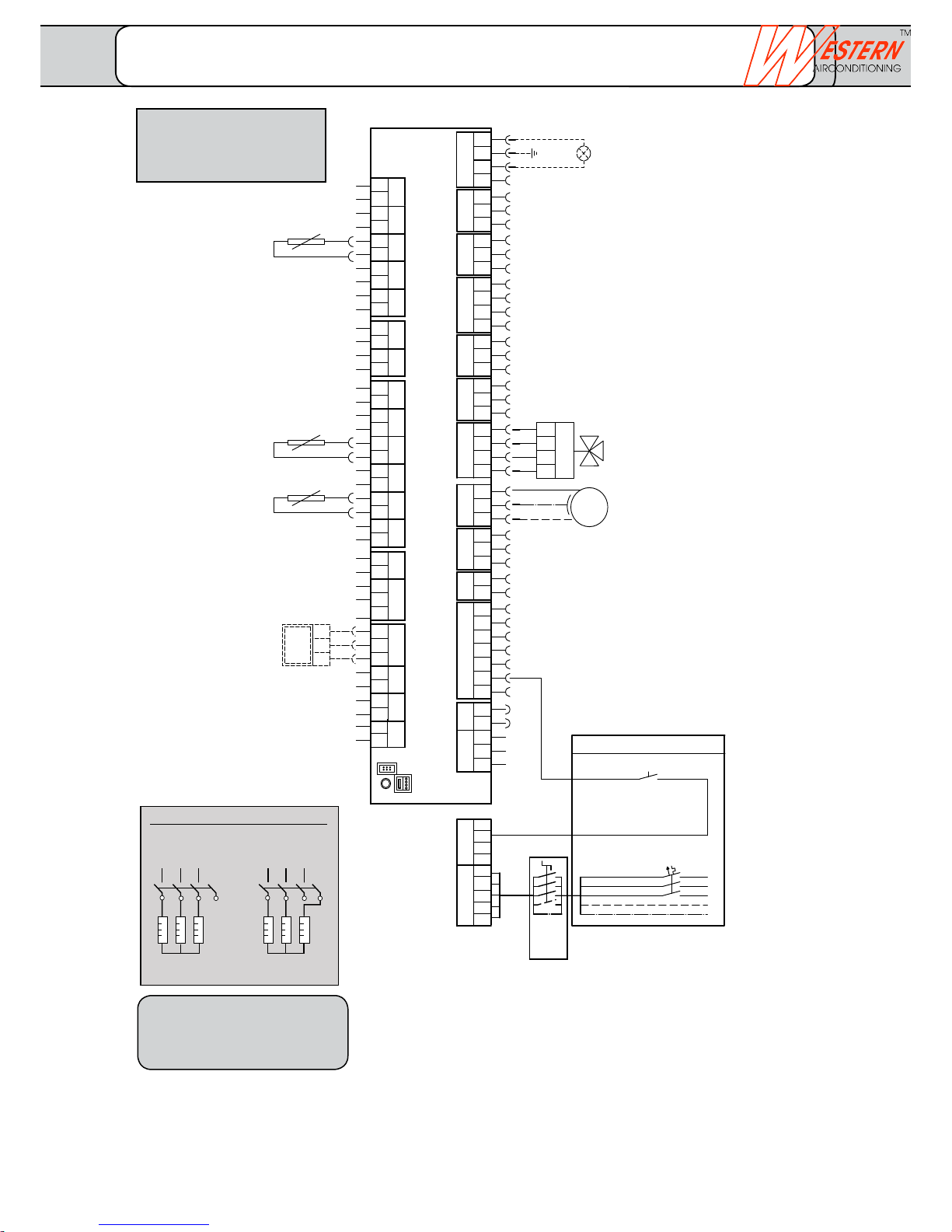
6 kW 3 kW
32241
6
110K6
2 4 6
14
3 2 1
L1
L2
L3
N
PE
QX4
PE
N
QX2
QX1
Q9
Q8
L3
N
N
L
L
EM
W
V
U
3
2
1
QX3
Y2
Y1
T
Q2
S
Q3
R
Ex7
EX6
EX5
EX4
EX3
EX2
EX1
N
PE
L
w
M
M
M
BX1
M
M
B91
M
B71
M
B1
M
B21
M
B9
M
B3
M
B81
G+
CL-
CL+
u
t
s
r
q
p
n
k
h
b
b
f
b
X
Y
K1
E11
Q
P
E10
E9
K
PE
N
PE
N
PE
N
PE
N
PE
N
PE
N
PE
N
CL-
CL+
CL-
CL+
N
PE
L
PE
L1
L2
X60
X30
BSB
3
2
U
3
2
V
2
W
4
3
3
3
2
X
2
Y
2
T
4
3
2
Z
4
3
3
2
S
3
2
R
2
Q
7
6
5
4
3
2
2
P
K
N
PE
L
w
2
u
2
t
2
z
2
y
2
x
2
s
2
r
2
q
2
p
2
n
2
k
2
h
2
f
2
3
e
2
3
b
2
b
2
b
2
BX3
BX2
B92
14
a
MB
DB
a
2
PE
QX6
QX5
N
Z
x
y
z
M
BX4
M
M
UX2
UX1
H3
M
H1
e
M
1~
L
PE
N
Zu
Auf
PE
N
UX1 Output 0 - 10 V
diverse functions
UX2 Output 0 - 10 V
diverse functions
BX4 Buffer storage
temperature sensor (B4)
BX3 DHW Temperature
sensor (B31)
BX2 Cooling agent temperature
sensor fluid (B83)
BX1 Hot gas temperature
sensor (B82)
B92 Source outlet
temperature sensor
B91 Source inlet
temperature sensor
B71 Return flow temperature sensor
Heat pump
B1 Flow temperature sensor
Heating circuit 1
B21 Flow temperature sensor
Heat pump
B9 External temperature sensor
B3 Domestic water temperature
sensor
B81 Hot gas temperature sensor
Compressor 1
H3 Digital 0..10 V input
H1 Digital 0..10 V input
BSB Room unit illumination
(optional)
QAA55 Phase 1 + 2
QAA75 Phase 1 - 3
BSB Connection for external
control units
BSB Connection for external
control units
LPB Connection (cascade, bivalence)
Heat pump controller Optiplus (RVS 61/3)
Fuse as per heat pump
type:
See separate sheet
Technical data
Attention:
The rotating field to the right is absolutely
necessary.
Local regulations must be followed.
Subject to technical changes.
Attention: Max. total reference current of all
230 V connections6 A
(max. 2 A per connection)
QX6 Alarm output (K10)
optional
QX5 Deflector valve free cooling (Y21)
QX4 Relay output 230 V
diverse functions
(modulated up to max. 1.4A)
QX3 Electric heating insert DHW (K6)
QX2 Pump (Q20)
QX1 Electric heating insert (K25)
(built-in)
Q9 Condenser pump
(built-in)
Q8 Brine pump (built-in)
(directly or via an internal power
contactor)
Y1 Heating circuit mixer 230 V
/Y2 (Y1 = open / Y2 = closed)
Q2 Heating circuit pump 230 V
Opt. Safety thermostat (ST)
in series with Q2
Q3 Deflector valve DHW 230 V
K1 Compressor 1
E11 Overload compressor 1
Ex7 Three phase current T
Ex6 Three phase current S
Ex5 Three phase current R
Ex4 Thermal relay source pump
Ex3 Pressure / flow source (E15)
Ex2 EW lock (E6)
Ex1 Reduced rate (E5)
E10 High pressure HP
E9 Low pressure BP
Internal wiring not
illustrated!!
on-site tableau
EW lock
EW lock: Contact is closed
when heat pump is enabled
Circuit breaker all-pole
Supply heat pump
Standard
Main
switch
installed
for HP
Terminal diagram for basic concept 02.00.10
FUSIO W 5 - FUSIO W 18
Connection electric heating insert K25 (internal)
FUSIO W 5 - FUSIO W 18
_______________________________________________________________________________
Western Airconditioning B.V. reserves the right to alter specifications
Page 41
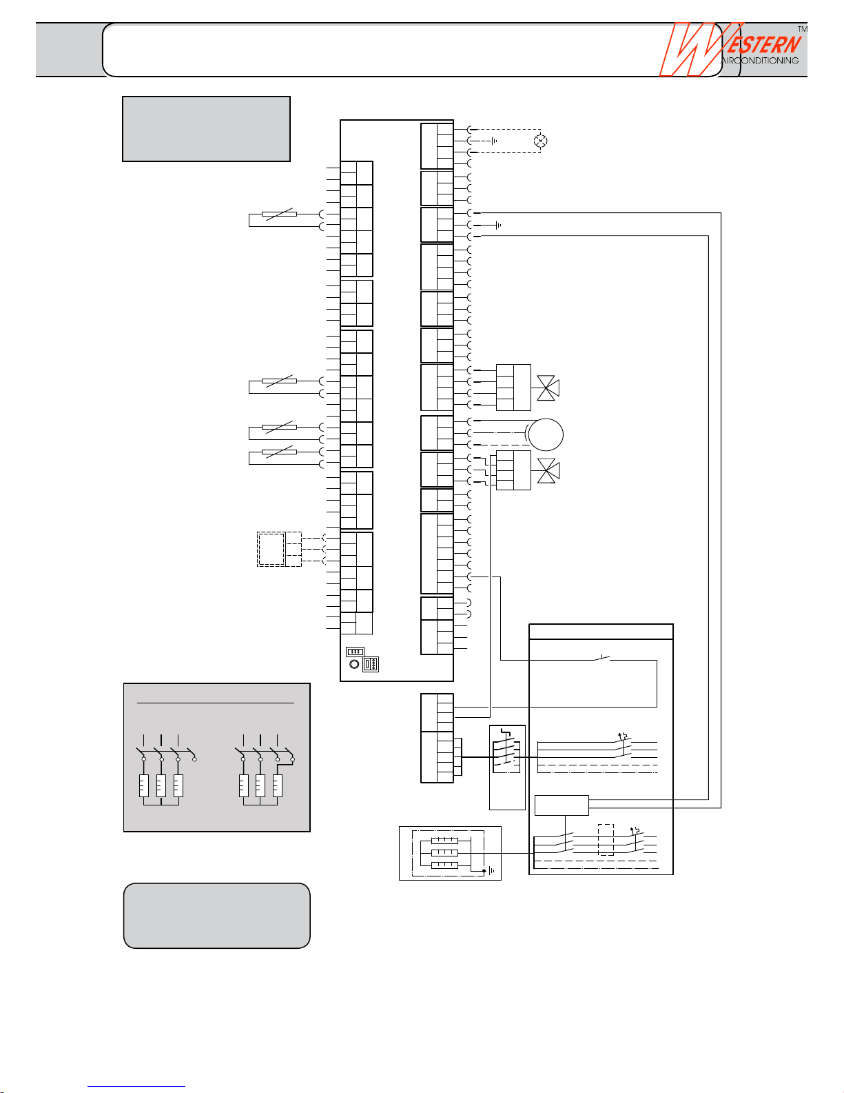
6 kW 3 kW
32241
6
110K6
2 4 6
14
3 2 1
L1
L2
L3
N
PE
QX4
PE
N
QX2
QX1
Q9
Q8
L3
N
N
L
L
EM
W
V
U
3
2
1
QX3
Y2
Y1
T
Q2
S
Q3
R
Ex7
EX6
EX5
EX4
EX3
EX2
EX1
N
PE
L
w
M
M
M
BX1
M
M
B91
M
B71
M
B1
M
B21
M
B9
M
B3
M
B81
G+
CLCL+
u
t
s
r
q
p
n
k
h
b
b
f
b
X
Y
K1
E11
Q
P
E10
E9
K
PE
N
PE
N
PE
N
PE
N
PE
N
PE
N
PE
N
CLCL+
CLCL+
N
PE
L
PE
L1
L2
X60
X30
BSB
3
2
U
3
2
V
2
W
4
3
3
3
2
X
2
Y
2
T
4
3
2
Z
4
3
3
2
S
3
2
R
2
Q
7
6
5
4
3
2
2
P
K
N
PE
L
w
2
u
2
t
2
z
2
y
2
x
2
s
2
r
2
q
2
p
2
n
2
k
2
h
2
f
2
3
e
2
3
b
2
b
2
b
2
BX3
BX2
B92
14
a
MB
DB
a
2
PE
QX6
QX5
N
Z
x
y
z
M
BX4
M
M
UX2
UX1
H3
M
H1
e
M
1~
L
PE
N
L
L
PE
N
L1
L2
L3
L1
L2
L3
N
PE
Zu
Auf
PE
N
only up to 10 kW
additional protection for 12 and 15 kW
UX1 Output 0 - 10 V
diverse functions
UX2 Output 0 - 10 V
diverse functions
BX4 Buffer storage
temperature sensor (B4)
BX3 DHW Temperature
sensor (B31)
BX2 Cooling agent temperature
sensor fluid (B83)
BX1 Hot gas temperature
sensor (B82)
B92 Source outlet
temperature sensor
B91 Source inlet
temperature sensor
B71 Return flow temperature sensor
Heat pump
B1 Flow temperature sensor
Heating circuit 1
B21 Flow temperature sensor
Heat pump
B9 External temperature sensor
B3 Domestic water temperature
sensor
B81 Hot gas temperature sensor
Compressor 1
H3 Digital 0..10 V input
H1 Digital 0..10 V input
BSB Room unit illumination
(optional)
QAA55 Phase 1 + 2
QAA75 Phase 1 - 3
BSB Connection for external
control units
BSB Connection for external
control units
LPB Connection (cascade, bivalence)
Heat pump controller Optiplus (RVS 61/3)
Fuse as per heat pump
type:
See separate sheet
Technical data
Attention:
The rotating field to the right is absolutely
necessary.
Local regulations must be followed.
Subject to technical changes.
Attention: Max. total reference current of all
230 V connections6 A
(max. 2 A per connection)
QX6 Alarm output (K10)
optional
QX5 Deflector valve free cooling (Y21)
QX4 Relay output 230 V
diverse functions
(modulated up to max. 1.4A)
QX3 Electric heating insert DHW (K6)
QX2 Pump (Q20)
QX1 Electric heating insert (K25)
(built-in)
Q9 Condenser pump
(built-in)
Q8 Brine pump (built-in)
(directly or via an internal power
contactor)
Y1 Heating circuit mixer 230 V
/Y2 (Y1 = open / Y2 = closed)
Q2 Heating circuit pump 230 V
Opt. Safety thermostat (ST)
in series with Q2
Q3 Deflector valve DHW 230 V
K1 Compressor 1
E11 Overload compressor 1
Ex7 Three phase current T
Ex6 Three phase current S
Ex5 Three phase current R
Ex4 Thermal relay source pump
Ex3 Pressure / flow source (E15)
Ex2 EW lock (E6)
Ex1 Reduced rate (E5)
E10 High pressure HP
E9 Low pressure BP
Internal wiring not
illustrated!!
on-site tableau
EW lock
EW lock: Contact is closed
when heat pump is enabled
Circuit breaker all-pole
Supply heat pump
Standard
K6 Electric heating insert DHW
Enable contactor
manual/auto/off
e.g. Hager ET321 (507403200)
EW Boiler release (RSE)
Main
switch
installed
for HP
Terminal diagram for basic concept 02.20.10
FUSIO W 5 - FUSIO W 18
Connection electric heating insert K25 (internal)
FUSIO W 5 - FUSIO W 18
_______________________________________________________________________________
Western Airconditioning B.V. reserves the right to alter specifications
Page 42
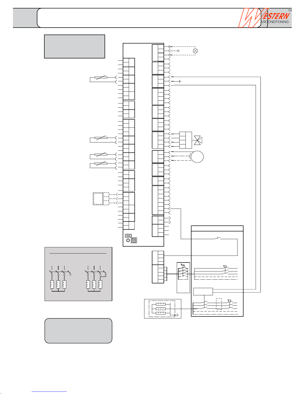
climate
cold heat
6 kW 3 kW
32241
6
110K6
2 4 6
14
3 2 1
L1
L2
L3
N
PE
QX4
PE
N
QX2
QX1
Q9
Q8
L3
N
N
L
L
EM
W
V
U
3
2
1
QX3
Y2
Y1
T
Q2
S
Q3
R
Ex7
EX6
EX5
EX4
EX3
EX2
EX1
N
PE
L
w
M
M
M
BX1
M
M
B91
M
B71
M
B1
M
B21
M
B9
M
B3
M
B81
G+
CL-
CL+
u
t
s
r
q
p
n
k
h
b
b
f
b
X
Y
K1
E11
Q
P
E10
E9
K
PE
N
PE
N
PE
N
PE
N
PE
N
PE
N
PE
N
CL-
CL+
CL-
CL+
N
PE
L
PE
L1
L2
X60
X30
BSB
3
2
U
3
2
V
2
W
4
3
3
3
2
X
2
Y
2
T
4
3
2
Z
4
3
3
2
S
3
2
R
2
Q
7
6
5
4
3
2
2
P
K
N
PE
L
w
2
u
2
t
2
z
2
y
2
x
2
s
2
r
2
q
2
p
2
n
2
k
2
h
2
f
2
3
e
2
3
b
2
b
2
b
2
BX3
BX2
B92
14
a
MB
DB
a
2
PE
QX6
QX5
N
Z
x
y
z
M
BX4
M
M
UX2
UX1
H3
M
H1
e
M
1~
L
PE
N
L1
L2
L3
L1
L2
L3
N
PE
PE
N
only up to 10 kW
additional protection for 12 and 15 kW
UX1 Output 0 - 10 V
diverse functions
UX2 Output 0 - 10 V
diverse functions
BX4 Buffer storage
temperature sensor (B4)
BX3 DHW Temperature
sensor (B31)
BX2 Cooling agent temperature
sensor fluid (B83)
BX1 Hot gas temperature
sensor (B82)
B92 Source outlet
temperature sensor
B91 Source inlet
temperature sensor
B71 Return flow temperature sensor
Heat pump
B1 Flow temperature sensor
Heating circuit 1
B21 Flow temperature sensor
Heat pump
B9 External temperature sensor
B3 Domestic water temperature
sensor
B81 Hot gas temperature sensor
Compressor 1
H3 Digital 0..10 V input
H1 Digital 0..10 V input
BSB Room unit illumination
(optional)
QAA55 Phase 1 + 2
QAA75 Phase 1 - 3
BSB Connection for external
control units
BSB Connection for external
control units
LPB Connection (cascade, bivalence)
Heat pump controller Optiplus (RVS 61)
Fuse as per heat pump
type:
See separate sheet
Technical data
Attention:
The rotating field to the right is absolutely
necessary.
Local regulations must be followed.
Subject to technical changes.
Attention: Max. total reference current of all
230 V connections6 A
(max. 2 A per connection)
QX6 Alarm output (K10)
optional
QX5 Deflector valve free cooling (Y21)
QX4 Relay output 230 V
diverse functions
(modulated up to max. 1.4A)
QX3 Electric heating insert DHW (K6)
QX2 Pump (Q20)
QX1 Electric heating insert (K25)
(built-in)
Q9 Condenser pump
(built-in)
Q8 Brine pump (built-in)
(directly or via an internal power
contactor)
Y1 Heating circuit mixer 230 V
/Y2 (Y1 = open / Y2 = closed)
Q2 Heating circuit pump 230 V
Opt. Safety thermostat (ST)
in series with Q2
Q3 Deflector valve DHW 230 V
K1 Compressor 1
E11 Overload compressor 1
Ex7 Three phase current T
Ex6 Three phase current S
Ex5 Three phase current R
Ex4 Thermal relay source pump
Ex3 Pressure / flow source (E15)
Ex2 EW lock (E6)
Ex1 Reduced rate (E5)
E10 High pressure HP
E9 Low pressure BP
Internal wiring not
illustrated!!
on-site tableau
EW lock
EW lock: Contact is closed
when heat pump is enabled
Circuit breaker all-pole
Supply heat pump
Standard
K6 Electric heating insert DHW
Enable contactor
manual/auto/off
e.g. Hager ET321 (507403200)
EW Storage release (RSE)
Main
switch
installed
for HP
Terminal diagram for basic concept 02.30.10
FUSIO W 5 - FUSIO W 18
Connection electric heating insert K25 (internal)
FUSIO W 5 - FUSIO W 18
_______________________________________________________________________________
Western Airconditioning B.V. reserves the right to alter specifications
Page 43
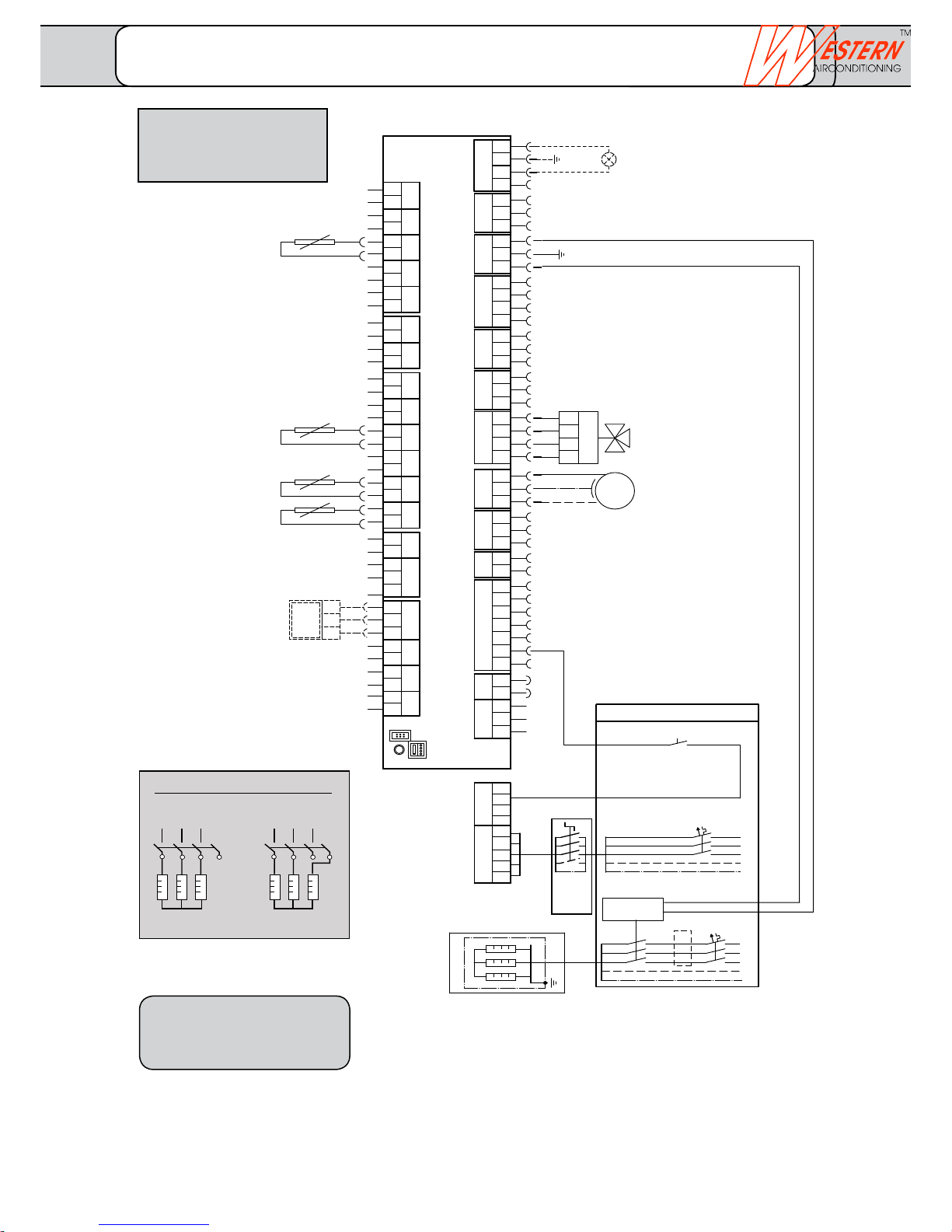
6 kW 3 kW
32241
6
110K6
2 4 6
14
3 2 1
L1
L2
L3
N
PE
QX4
PE
N
QX2
QX1
Q9
Q8
L3
N
N
L
L
EM
W
V
U
3
2
1
QX3
Y2
Y1
T
Q2
S
Q3
R
Ex7
EX6
EX5
EX4
EX3
EX2
EX1
N
PE
L
w
M
M
M
BX1
M
M
B91
M
B71
M
B1
M
B21
M
B9
M
B3
M
B81
G+
CL-
CL+
u
t
s
r
q
p
n
k
h
b
b
f
b
X
Y
K1
E11
Q
P
E10
E9
K
PE
N
PE
N
PE
N
PE
N
PE
N
PE
N
PE
N
CL-
CL+
CL-
CL+
N
PE
L
PE
L1
L2
X60
X30
BSB
3
2
U
3
2
V
2
W
4
3
3
3
2
X
2
Y
2
T
4
3
2
Z
4
3
3
2
S
3
2
R
2
Q
7
6
5
4
3
2
2
P
K
N
PE
L
w
2
u
2
t
2
z
2
y
2
x
2
s
2
r
2
q
2
p
2
n
2
k
2
h
2
f
2
3
e
2
3
b
2
b
2
b
2
BX3
BX2
B92
14
a
MB
DB
a
2
PE
QX6
QX5
N
Z
x
y
z
M
BX4
M
M
UX2
UX1
H3
M
H1
e
M
1~
L
PE
N
L1
L2
L3
L1
L2
L3
N
PE
PE
N
only up to 10 kW
additional protection for 12 and 15 kW
UX1 Output 0 - 10 V
diverse functions
UX2 Output 0 - 10 V
diverse functions
BX4 Buffer storage
temperature sensor (B4)
BX3 DHW Temperature
sensor (B31)
BX2 Cooling agent temperature
sensor fluid (B83)
BX1 Hot gas temperature
sensor (B82)
B92 Source outlet
temperature sensor
B91 Source inlet
temperature sensor
B71 Return flow temperature sensor
Heat pump
B1 Flow temperature sensor
Heating circuit 1
B21 Flow temperature sensor
Heat pump
B9 External temperature sensor
B3 Domestic water temperature
sensor
B81 Hot gas temperature sensor
Compressor 1
H3 Digital 0..10 V input
H1 Digital 0..10 V input
BSB Room unit illumination
(optional)
QAA55 Phase 1 + 2
QAA75 Phase 1 - 3
BSB Connection for external
control units
BSB Connection for external
control units
LPB Connection (cascade, bivalence)
Heat pump controller Optiplus (RVS 61)
Attention:
The rotating field to the right is absolutely
necessary.
Local regulations must be followed.
Subject to technical changes.
Attention: Max. total reference current of all
230 V connections6 A
(max. 2 A per connection)
QX6 Alarm output (K10)
optional
QX5 Deflector valve free cooling (Y21)
QX4 Relay output 230 V
diverse functions
(modulated up to max. 1.4A)
QX3 Electric heating insert DHW (K6)
QX2 Pump (Q20)
QX1 Electric heating insert (K25)
(built-in)
Q9 Condenser pump
(built-in)
Q8 Brine pump (built-in)
(directly or via an internal power
contactor)
Y1 Heating circuit mixer 230 V
/Y2 (Y1 = open / Y2 = closed)
Q2 Heating circuit pump 230 V
Opt. Safety thermostat (ST)
in series with Q2
Q3 Deflector valve DHW 230 V
K1 Compressor 1
E11 Overload compressor 1
Ex7 Three phase current T
Ex6 Three phase current S
Ex5 Three phase current R
Ex4 Thermal relay source pump
Ex3 Pressure / flow source (E15)
Ex2 EW lock (E6)
Ex1 Reduced rate (E5)
E10 High pressure HP
E9 Low pressure BP
Internal wiring not
illustrated!!
on-site tableau
EW lock
EW lock: Contact is closed
when heat pump is enabled
Circuit breaker all-pole
Supply heat pump
Standard
K6 Electric heating insert DHW
Enable contactor
manual/auto/off
e.g. Hager ET321 (507403200)
EW Storage release (RSE)
Main
switch
installed
for HP
Fuse as per heat pump
type:
See separate sheet
Technical data
Terminal diagram for basic concept 02.40.10
FUSIO W 5 - FUSIO W 18
Connection electric heating insert K25 (internal)
FUSIO W 5 - FUSIO W 18
_______________________________________________________________________________
Western Airconditioning B.V. reserves the right to alter specifications
Page 44

FUSIOW23062016
Western Airconditioning B.V.
De Wel 10, 3871 MV
HOEVELAKEN
Tel. +31 (0) 33 247 7800
www.western.nl
_______________________________________________________________________________
Western Airconditioning B.V. reserves the right to alter specifications
 Loading...