

Western Airconditioning Doppio 4, Doppio 2 EX, Doppio 2, Doppio 4 EX Technical Information Manual
Page 1
Western Airconditioning B.V. Tel. +31 (0) 33 247 78 00 www.western.nl
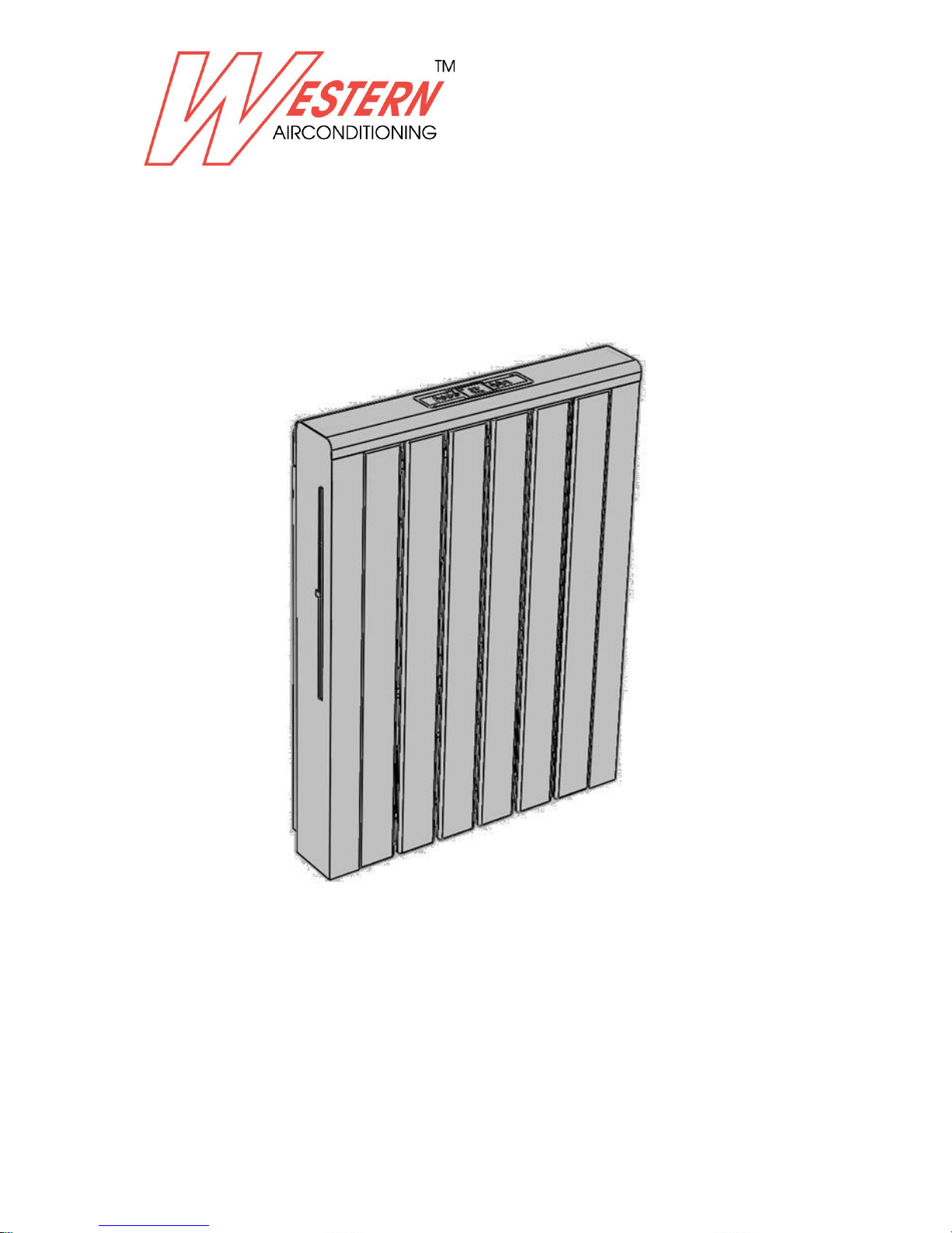
DOPPIO (EXCLUSIVE)
hybrid fancoil
Technical information manual
Technical information manual
Page 2
Western Airconditioning B.V. reserves the right to alter specifications
2
Index
1. GENERAL INFORMATION 3
1.1 FUNDAMENTAL SAFETY RULES 3
1.2 SAFETY PRECAUTIONS 4
2. TECHNICAL FEATURE 5
2.1 PARTICULAR DESCRIPTION AND MAIN COMPONENTS 5
2.2 TECHNICAL DATA 6
2.3 DIMENSIONS AND WEIGHTS 7
3. BEFORE INSTALLATION 8
3.1 ACCESSORY 8
3.2 SAFETY CONSIDERATIONS 8
3.3 OPERATING LIMITS 8
3.4 BEFORE INSTALLATION 9
3.5 SELECT LOCATION 9
4. INSTALLATION 10
4.1 POSITIONING THE UNIT 10
4.2 PLUMBING CONNECTION SIDE 11
4.3 WALL MAP 13
4.4 ELECTRICAL CONNECTION SIDE 15
4.5 INSTALLATION METHOD 17
4.6 FIX RADIATOR, COVER AND ALL THE METAL SHEET 34
4.7 HOW TO ACCESS AIR VENT AND WATER PURGE 36
5. ADDITIONAL INFORMATIONS 37
5.1 THERMOSTATIC+2 WAY VALVE BOX KIT 37
5.2 THERMOSTATIC +3 WAY BY PASS VALVE BOX KIT 38
5.3 4-PIPES 3 WAY BY PASS VALVE BOX KIT 40
5.4 CATALITIC FILTER 42
5.5 METAL WALL MAP 42
5.6 HUMIDISTAT KIT 43
5.7 WALL PAD KIT 44
6. NOTE FOR THE FINAL CUSTOMER AND MAINTENANCE 45
7. TABLE OF ANOMALIES AND REMEDIES 52
Page 3
Western Airconditioning B.V. reserves the right to alter specifications
3
1. GENERAL INFORMATION
Thank you for choosing this excellent and innovative Fan coils –Radiator for controlling the climate in your
home.
This product is Patent BS BS2007A000147 and protect from any imitations.
Please read this instruction use and installation manual carefully before installing and starting up the appliance.
Following the indications contained in this manual will ensure that the appliance continues to function
perfectly over time.
This appliance must be installed by an authorized installer who, on completion of the work, will release a
declaration of conformity to the client in respect of the laws in force and the indications given by Manufacturer
in the instructions leaflet supplied together with the appliance. These appliances have been designed both for
conditioning and/or heating environments and must be destined for this use only and compatibly with their
performance characteristics. Manufacture accepts no responsibility, either contractual or extra contractual, for
any damage caused to persons, animals of property as a result of incorrect installation, adjustment or
maintenance or improper use.
This instruction leaflet is an integral part of the appliance and consequently must be kept carefully and must
ALWAYS accompany the appliance, even when it is passed to a new owner or user or transferred onto another
system. If it is lost or damaged, please contact the Manufacturer customer service .
All repair or maintenance interventions must be performed by the technical service department or by
professionally qualified personnel as foreseen in this booklet. Do not modify or intervene on the appliance as
this could create dangerous situations and the manufacturer will not be responsible for any damage caused.
1.1 FUNDAMENTAL SAFETY RULES
Remember that some fundamental safety rules should be followed when using a product that uses electricity
and water, such as:
It is forbidden for the appliance to be used by children or unassisted disabled persons.
It is forbidden to touch the appliance with wet hands or body when barefoot.
It is forbidden to carry out any cleaning before having disconnected the appliance from the electricity
mains supply by turning the system master switch to "OFF".
It is forbidden to modify the safety or adjustment devices or adjust without authorization and
indications of the manufacturer.
It is forbidden to pull, cut or knot the electrical cables coming out of the appliance, even if it is
disconnected from the mains supply.
It is forbidden to poke objects or anything else through the inlet or outlet grills.
It is forbidden to open the doors which access the internal parts of the appliance without first turning
the system master switch to "OFF".
It is forbidden to dispose of or leave in the reach of children the packaging materials which could
become a source of danger.
It is forbidden to climb onto the appliance or rest any object on it.
The external parts of the appliance can reach temperatures of more than 70°C.
Page 4
Western Airconditioning B.V. reserves the right to alter specifications
4
DANGER FROM BURNS - TAKE CARE WHEN TOUCHING
1.2 SAFETY PRECAUTIONS
Installing, starting up, and servicing water terminal can be hazardous due to system pressure, electrical
components, and equipment location, etc.
Only trained, qualified installers and service personnel are allowed to install, start-up, and service this
equipment. Untrained personnel can perform basic maintenance functions such as cleaning coils. All other
operations should be performed by trained service personnel.
When handling the equipment, observe precautions in the manual and on tags, stickers, and labels attached to
the equipment. Follow all safety codes. Wear safety glasses and work gloves. Keep quenching cloth and fire
extinguisher nearby when brazing. Read the instructions thoroughly and follow all warnings or cautions in
literature and attached to the unit. Consult local building codes and current editions of national as well as local
electrical codes. Recognize the following safety information: Incorrect handling could result in personal injury
or death. Incorrect handling may result in minor injury, or damage to product or property.
All electric work must be performed by a licensed technician according to local regulations and the instructions
given in this manual. Before installing, modifying, or servicing system, main electrical disconnect switch must
be in the OFF position. There may be more than 1 disconnect switch. Lock out and tag switch with a suitable
warning label. Never supply power to the unit unless all wiring an d tubing are completed, reconnected and
checked. This system adopts highly dangerous electrical voltage. Incorrect connection or inadequate grounding
can cause personal injury or death. Stick to the wiring diagram and all the instructions when wiring. Have the
unit adequately grounded in accordance with local electrical codes. All installation or repair work shall be
performed by your dealer or a specialized subcontractor as there is the risk of fire, electric shock, explosion or
injury.
Properly insulate any tubing running inside the room to prevent the water from damaging the wall.
Make a proper provision against noise when the unit is installed at a telecommunication center or
hospital.
Provide an electric leak breaker when it is installed in a watery place.
Never wash the unit with water.
Should any emergency occur, stop the unit and disconnect the power immediately.
Handle unit transportation with care. The unit should not be carried by only one person if it is more
than 20kg.
Never touch the heat exchanger fins with bare hands.
Do not have the unit operate without air filter.
BEFORE AND DURING THE STARTING UP OF THE UNIT (SO WHEN THE UNIT IS ON AND THE VALVE IS
OPENED), VERIFY THE ABSENCE OF WATER LEAKAGE IN ALL PIPES AND HYDRAULIC CONNECTIONS IN
BOTH INTERNAL AND EXTERNAL PART OF THE UNIT.
Page 5
Western Airconditioning B.V. reserves the right to alter specifications
5
2. TECHNICAL FEATURES
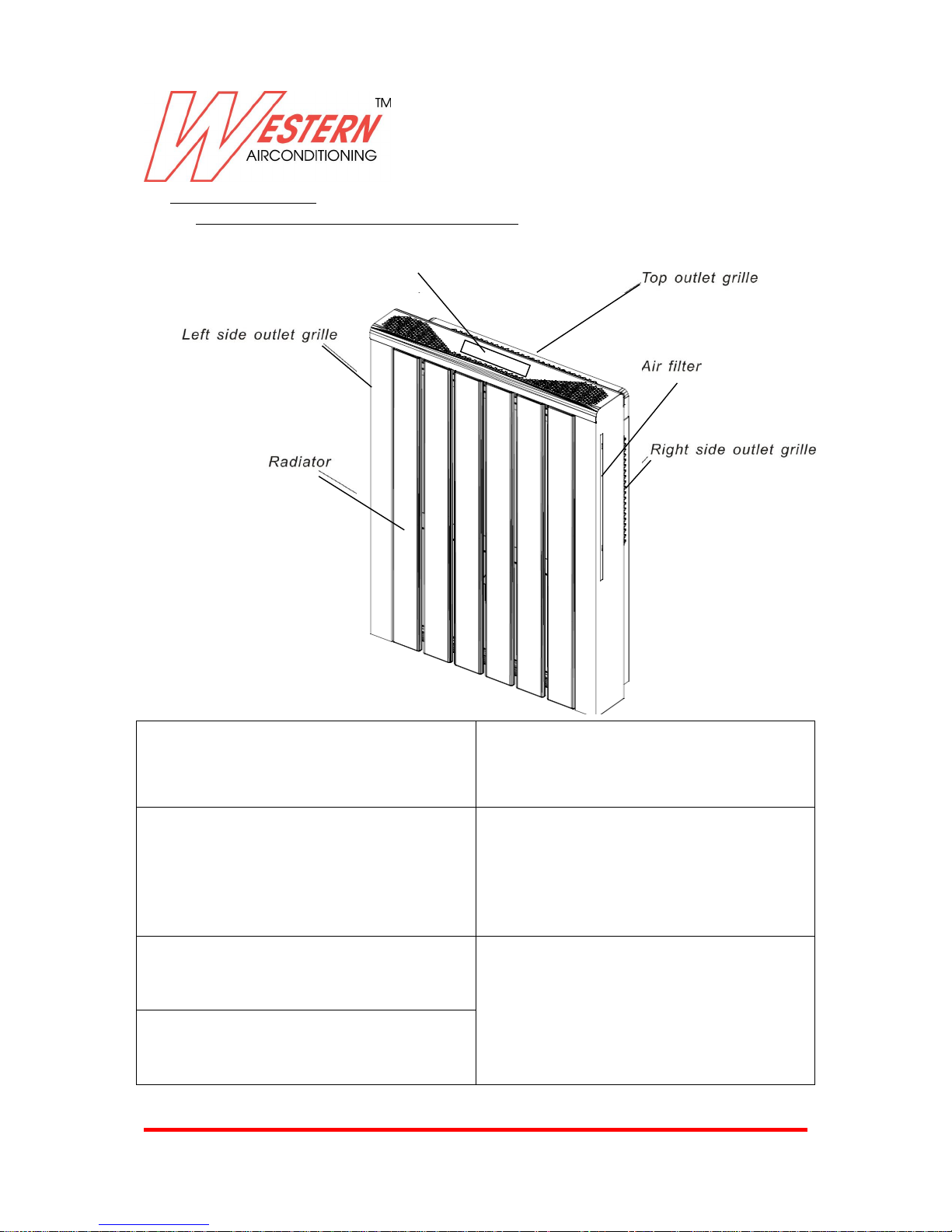
2.1 PARTICULAR DESCRIPTION AND MAIN COMPONENTS
Supporting structure in high resistance
galvanized and epoxy polyester painted steel
sheet.
Heat exchange battery made in copper pipes
and aluminum fins with high efficiency
turbulence and oxidation treatment .
Frontal Radiator ; made in steel or aluminum
epoxy polyester painted , the particular
shape supply high efficiency and high
thermal inertia in heating mode .
Ventilating unit consisting of a radial fan
with special patent blade in ABS glass fiber
reinforced (extremely quiet) mounted on
anti-vibration supports in EPDM, balanced
statically and dynamically, and splined
directly onto the motor shaft .
Low consumption Electric motor, single
phase with resin-coated coil mounted on
anti-vibration supports in EPDM.
Primary and catalytic filter , big filter surface with
low air speed to obtain maximum filter efficiency
Static switch, 0 dB(A) in heating mode
Display
Page 6
Western Airconditioning B.V. reserves the right to alter specifications
6
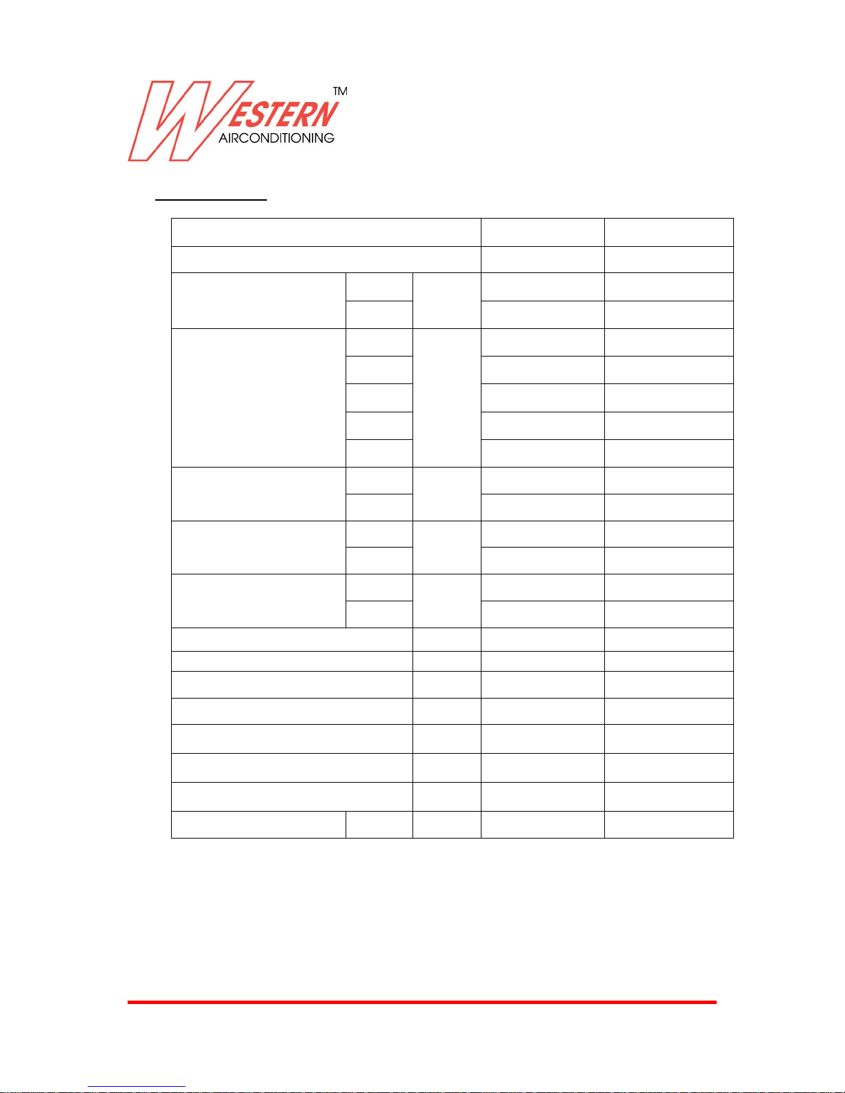
2.2 TECHNICAL DATA
Model
Doppio 2 (EX)
Doppio 4 (EX)
Number of fan blowers
Single
Dual
Cooling capacity(max)
7-12℃
W
2169
3585
16-22℃
554
707
Heating capacity(max)
50℃
W
2498
3763
70-60℃
4237
6528
75-65℃
4765
7357
45-40℃
2023
3136
35-30℃
915
1418
Air flow
Min
m3/h
150
250
Max
400
750
Sound power
Min
dB(A)
0
0
Max
54.1
56.3
Sound pressure at 1m
Min
dB(A)
0
0
Max
47.9
50.1
Power supply
(V/Ph/Hz)
230/1/50
230/1/50
Max Fan motor power
W
45
98
Cooling water flow rate
L/h
376
616
Cooling water pressure drop
kPa
16.8
32.3
Cond. Drain connection O.D.
mm
16.5
16.5
Coil water content
liter
1.1
1.8
Radiator water content
liter
3.03
5.05
Water connection
IN/OUT
in
3/4"
3/4"
1. Eurovent Certified Specification.
2. Standard Cooling Capacity is tested under the condition 27 °C Dry Bulb /19.5 °C Wet Bulb entering air
temperature, 7 °C entering water and 12 °C leaving water temperature with water flow rates specified.
3. Standard Heating Capacity is tested under the condition 20 °C Dry Bulb entering air temperature, 50 °C entering
water temperature with water flow rates same as for the cooling test +radiator.
4. Air flow measured with clean filter
5. Sound power measured according to ISO 3741:1998
Page 7
Western Airconditioning B.V. reserves the right to alter specifications
7
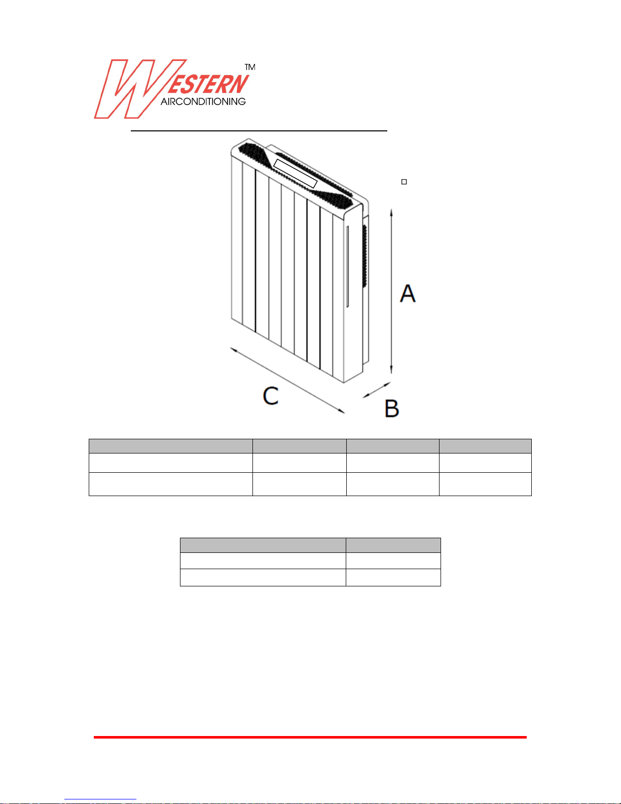
2.3 DIMENSIONS AND WEIGHTS (2 AND 4 PIPES VERSION)
Model
A ( mm )
B ( mm )
C ( mm )
KONRAD KRA-2.0EX
757
166
578
KONRAD KRA-4.0EX
757
166
894
Net weight (without water)
Kg
KONRAD KRA-2.0EC
32
KONRAD KRA-4.0EC
52
Page 8
Western Airconditioning B.V. reserves the right to alter specifications
8
3. BEFORE INSTALLATION
3.1 ACCESSORY
First check the contents inside package. Factory supply all accessory necessary for installation.
Standard and optional accessory List :
N° 1 Wall bracket (standard)
N° 1 Drainage pipe (standard)
N° 1 User and installation manual(standard)
N° 1 Template wall map (standard)
N° 1 Special wrench tooling and Allen key (standard)
N.2 flexible pipe with N° 1 H shape connection valve and stop valves (optional)
The appliance should be installed in accordance with national wiring regulation.
3.2 SAFETY CONSIDERATIONS
When working on air conditioning equipment, observe precautions in this manual, and on plates and
tables attached to the unit. Follow all safety codes and other safety precautions that may apply.
Installing and servicing air conditioning equipment should be done by trained and qualified service
personnel only. Untrained personnel can perform only basic maintenance functions such as cleaning
coils, filters and replacing filters.
Ensure that the electrical supply and frequency are adequate for the operating current required for
this specific installation.
WARNING- Before any service or maintenance operations turn off the main power switch.
The manufacturer denies any responsibility and warranty shall be void if these installation instructions
are not observed.
Never switch off the power main supply when unit is operating in the cooling cycle. To switch off the
fan coil unit use only the ON-OFF button.
This avoids over-flow in the drain pan, by allowing the pump to drain any condensate water due to
regulating valve losses when chiller is working.
3.3 OPERATING LIMITS
Power supply
Volts
Phase
Hz
230 1 50
Temperature range between +5°C and +32 °C- 60 % U.R.
Minimum entering water temperature: +4 °C
Maximum entering water temperature: +80 °C
Water side maximum pressure: 600 KPa- ( 6 Bar )
Page 9
Western Airconditioning B.V. reserves the right to alter specifications
9
3.4 BEFORE INSTALLATION
The installation site must be established by the system designer or other qualified professional, taking
account of the technical requisites and current standards and legislation.
Fan coils radiator must be installed by an authorized company only.
Fan coils radiator are designed for floor standing installation .
They must be installed in such a way as to enable treated air to circulate throughout the room and in
respect of the minimum distances required for technical maintenance operations.
It is advisable to place the unit close to the installation site without removing it from the packaging.
Do not put heavy tools or weights on the packaging.
Upon receipt, the unit and the packaging must be checked for damage sustained in transit and if
necessary, a damage claim must be filed with the shipping company.
Check immediately for installation accessories inside the packaging.
Check and note the unit serial number.
3.5 SELECT LOCATION
Do not install the unit in rooms where flammable gas or alkaline acid substances are present.
Aluminum/copper coils and/or internal plastic components can be damaged irreparably.
Do not install in ambient where oil vapors drawn in by treated air might deposit on the coils and alter
their performance or damage the internal plastic parts of the unit.
It is recommended to position the unit as centrally as possible in the room to ensure optimum air
distribution.
Check that it is possible to remove filter , to allow enough clearance for maintenance and servicing
operations.
The appliance shall not be installed in the laundry.
The appliance shall be installed in accordance with national wiring regulations.
Page 10
Western Airconditioning B.V. reserves the right to alter specifications
10
4. INSTALLATION
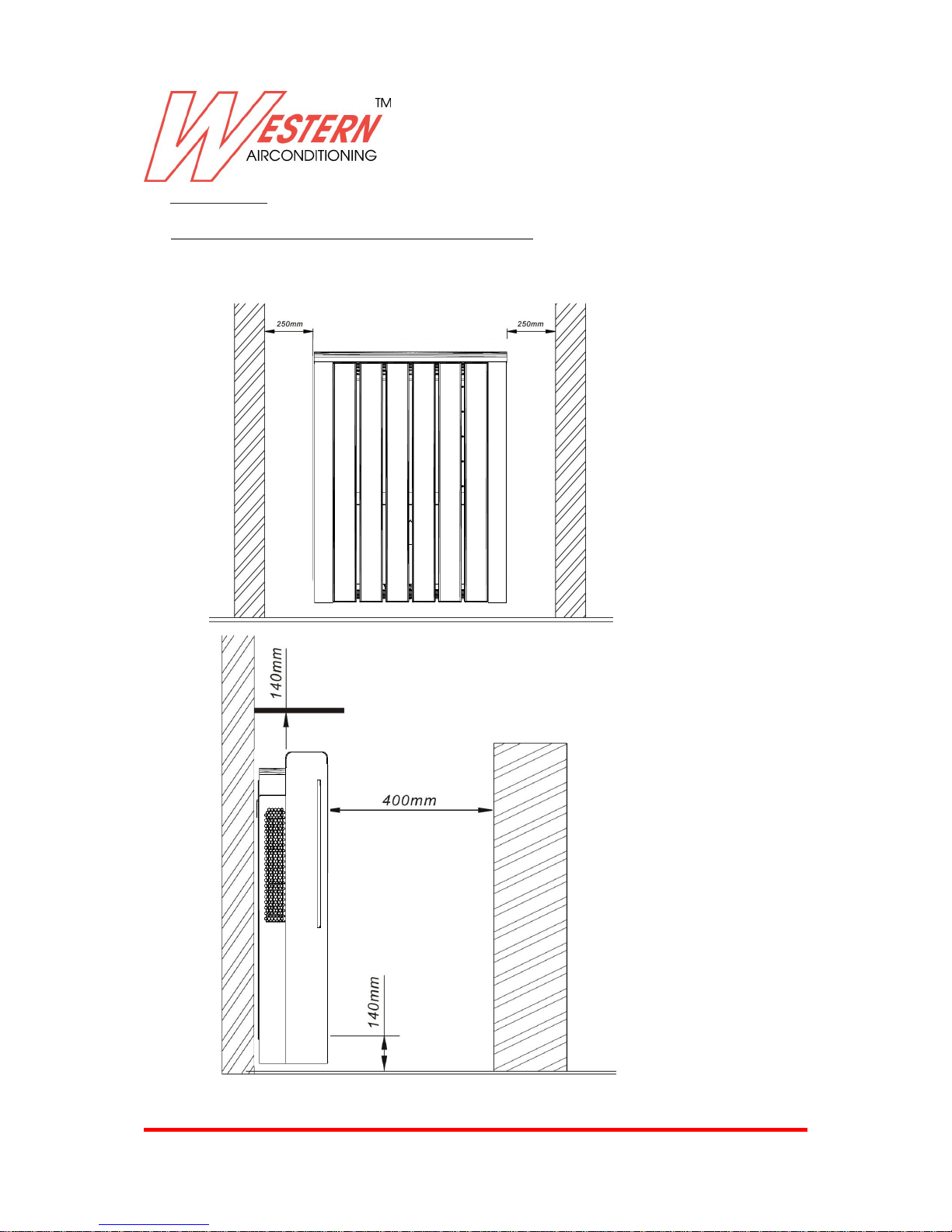
4.1 POSITIONING THE UNIT ( minimum distance from obstacle )
The dimensions of the space necessary for correct installation of the appliance including the minimum
permissible distances to adjacent structures.
Note : Machine is supplied with paper wall map to avoid any mistake from installer .
Page 11
Western Airconditioning B.V. reserves the right to alter specifications
11
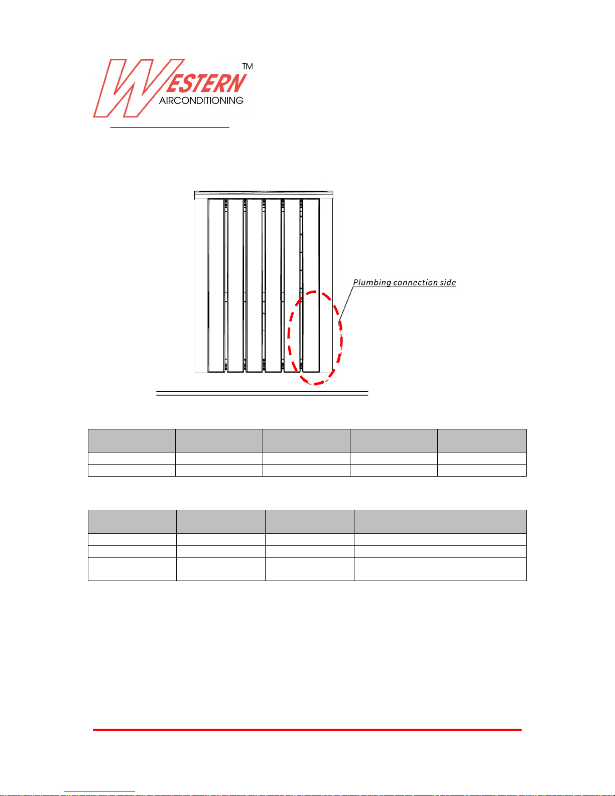
4.2 PLUMBING CONNECTION SIDE
The position of plumbing fitting must be from right side , from the wall or from the floor.
The choice and size of the plumbing lines is decided by the designer , who must operate in compliance
with good man ship and current legislation .
CONNECTION PIPES DIAMETERS
Model
Water Flow Max
( L/h )
Ø Steel ( “ )
Ø Copper (mm)
Ø Multilayer pipe
(mm)
Doppio 2 (EX)
376
1/2
18/22
20
Doppio 4 (EX)
616
3/4
18/22
26
Max speed suggested V = m/sec :
Pipe Type
Principal pipe
m/sec
Secondary pipe
Connection pipe to the indoor terminal (
fan coils + radiator )
Steel pipe
1.5 – 2.5
0.5 – 1.5
0.2 – 0.7
Copper Pipe
0.9 – 1.2
0.5 – 1.2
0.2 – 0.5
Multilayer plastic
pipe
1.5 – 2.5
0.5 – 1.5
0.2 – 0.7
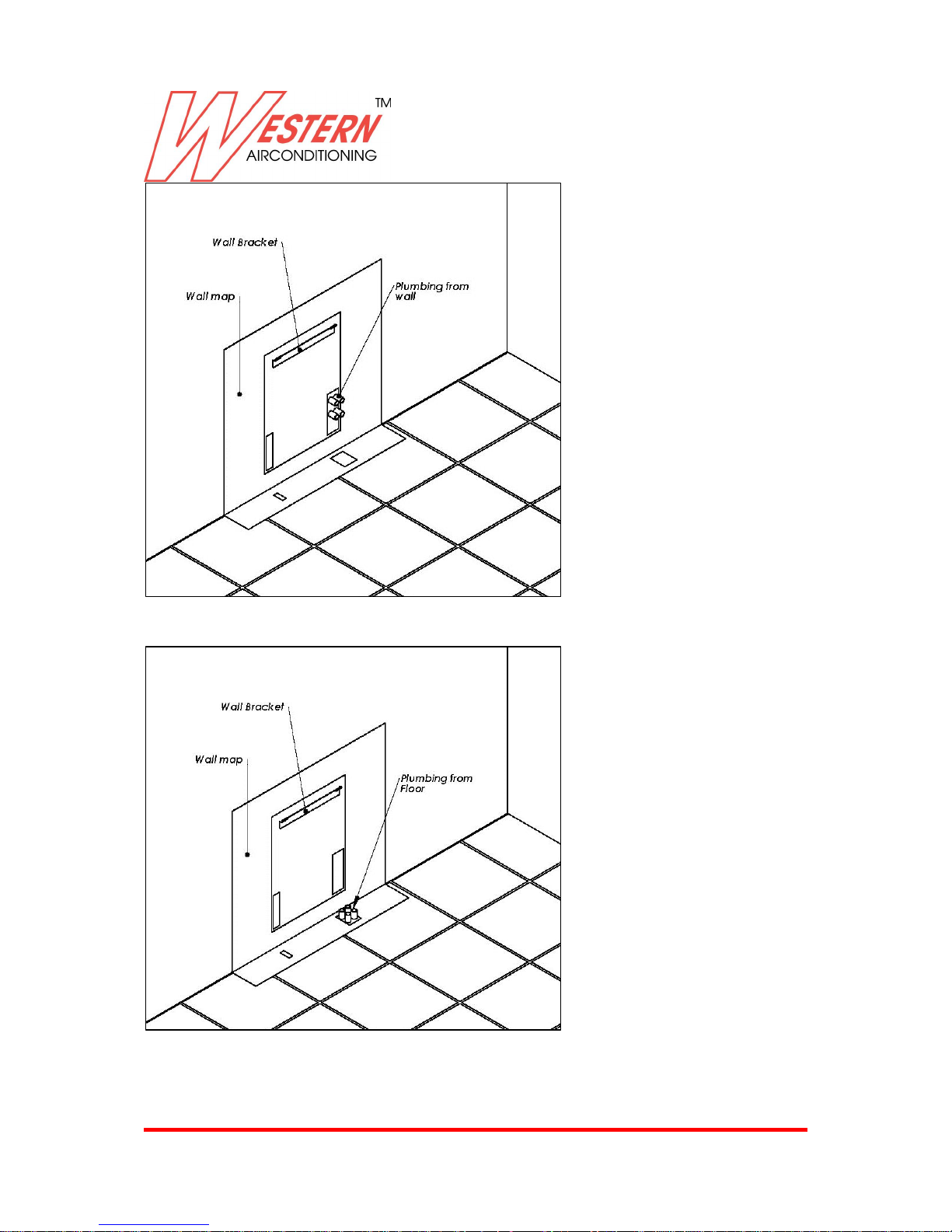
EXAMPLE OF PLUMBING CONNECTION FOR 2 AND 4 PIPES INSTALLATION
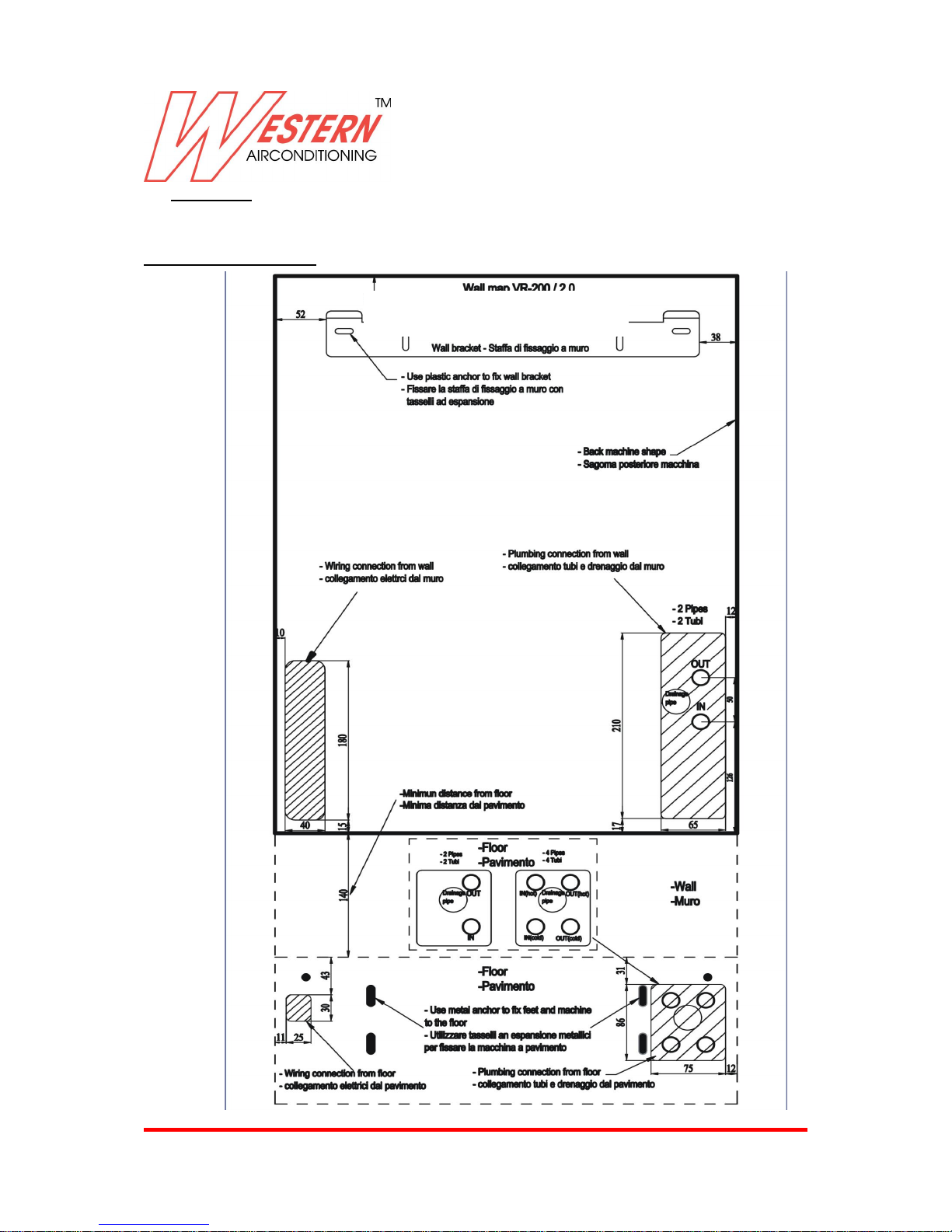
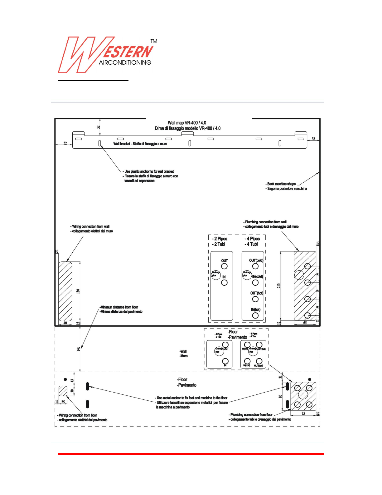
Machine is supplied with paper wall map to identify fast the right plumbing connection position if
pipes coming from wall or from the floor .
Is possible to use also strongest pipe wall map metal made , useful to reuse many time.
Below is reported the images and quote for fast understanding .
Page 12
Western Airconditioning B.V. reserves the right to alter specifications
12
Plumbing from wall
Plumbing from floor
Page 13
Western Airconditioning B.V. reserves the right to alter specifications
13
4.3 WALL MAP
Wall map Doppio 2 (EX)
Page 14
Western Airconditioning B.V. reserves the right to alter specifications
14
Wall map Doppio 4 (EX)
Page 15
Western Airconditioning B.V. reserves the right to alter specifications
15
4.4 ELECTRICAL CONNECTION SIDE
Important
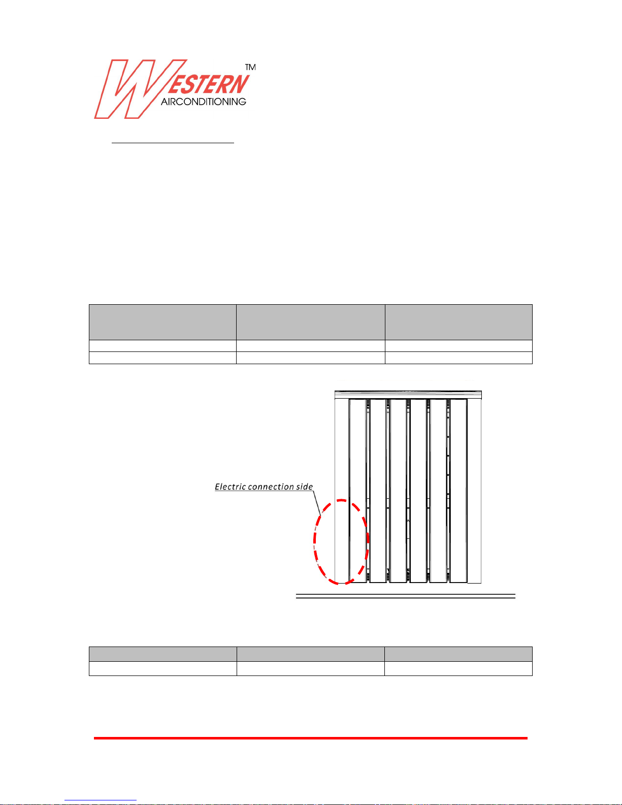
The position of electric connection must be from left side , from the wall or from the floor.
The power supply must pass through a specific master switch fitted with delayed fuses or a 2A thermo
magnetic circuit breaker. By law, an anti-disturbance filter is mounted on the cabling bracket to
discharge to heart a micro-current therefore it is advisable to use a delayed differential in installations
with more than one unit .
For safety motives, the main disconnecting switch should be located in a visible place , close to device
powered .
The power cables must be fitted with copper conductors with the following individual section ( the
values indicated refer to a maximum line length 15 m ) .
The cables must be type H07-RR-F and have a minimum diameter of 8 mm .
Model
Conductor section sq mm –
Ground power ( phase and neutral
)
Ground
Doppio 2 (EX)
1.5
1.5
Doppio 4 (EX)
1.5
1.5
Signal wiring
To avoid interference is advised to put power cable and signal cable in different plastic tube inside the
wall
Model
Signal cable sq mm
Note
Doppio 2 (EX), Doppio 4 (EX)
0.50-0.70
H07VK Type
EXAMPLE OF ELECTRIC CONNECTION
Page 16
Western Airconditioning B.V. reserves the right to alter specifications
16
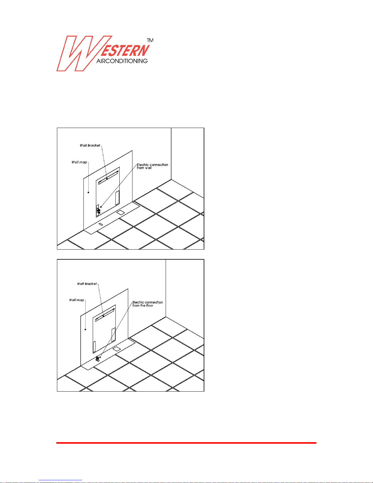
Machine is supplied with paper wall map to identify fast the right electric connection position if
coming from wall or from the floor .
Is possible supply also strongest pipe wall map metal made , useful to reuse many time .
Below is reported the images and quote for fast understanding .
Don’t use power cable within signal cable ( coming from wall pad or external sensor ) inside the same
corrugated pipe , because is possible to have signal interference .
Electric wiring from wall
Electric wiring from floor
If the supply cord is damaged, it must be replaced by the manufacture its service agent or a similarly
qualified person in order to avoid a hazard.
Page 17
Western Airconditioning B.V. reserves the right to alter specifications
17
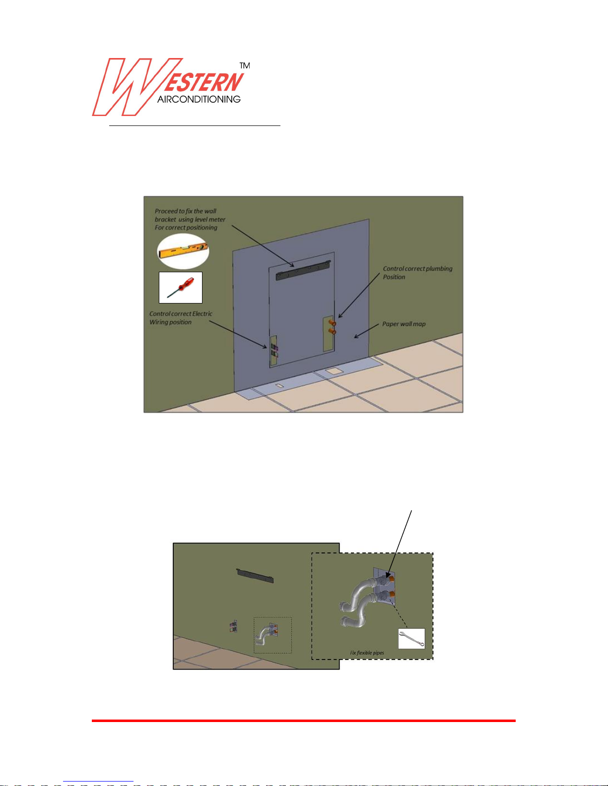
4.5 INSTALLATION METHOD ( 2 Pipes Example )
Before to proceed to fix the machine , using paper wall map , control the correct pipe correspondence
and wall bracket position .
Proceed to drill plastic anchor hole for metal wall bracket and pay attention to fix it after checked
correct positioning with level meter.
Remove paper wall map, and proceed to fix flexible water pipe using kit supplied from factory. The
kit( optional) includes soft pipes and H shape valve. Pipe kits have correct diameter and length for
easy installation.
H shape ball valve
(optional)
Page 18
Western Airconditioning B.V. reserves the right to alter specifications
18
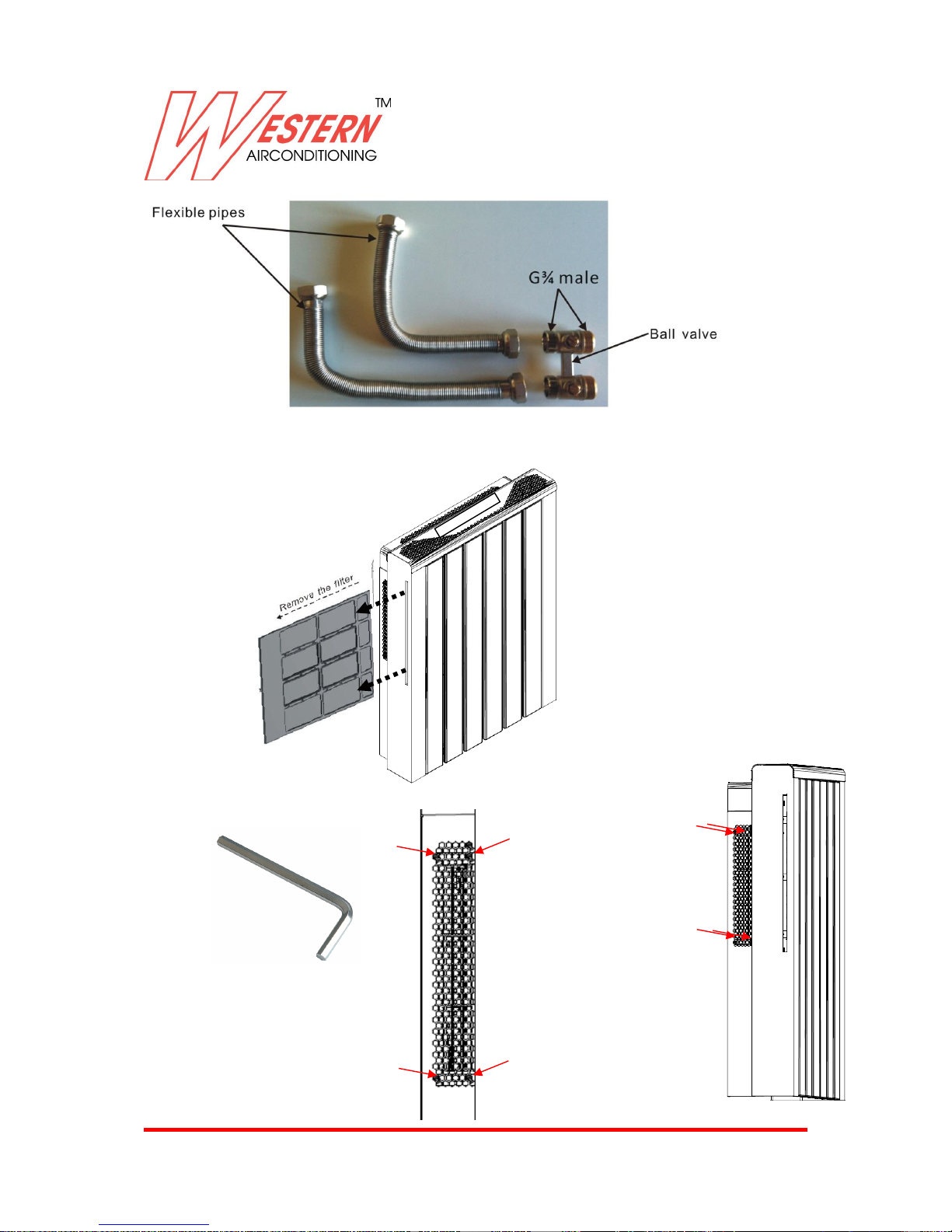
Remove filter
Take out n.4+4 screws from left and right metal flanks by Allen key.
Optional
Page 19
Western Airconditioning B.V. reserves the right to alter specifications
19
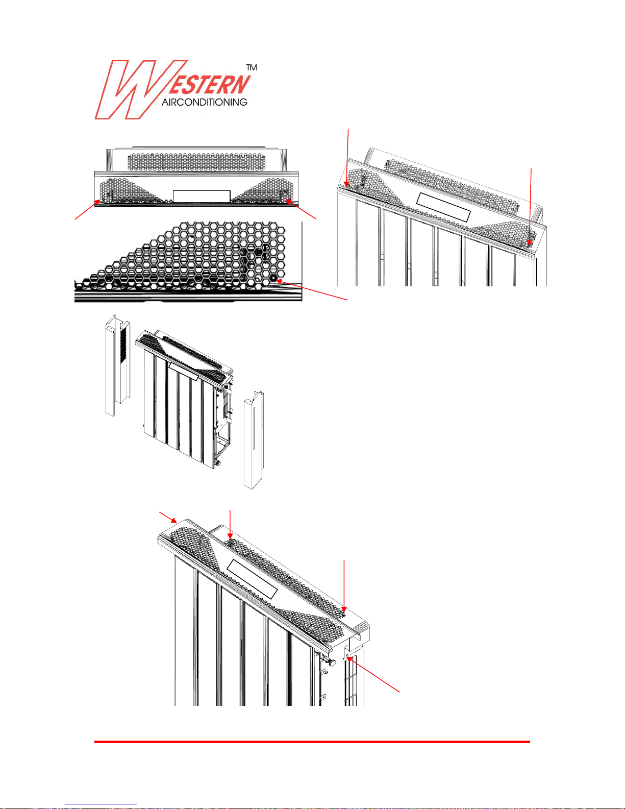
Take out n.2 screws by the top panel by Allen key. Remove the metal flanks
In the same way, remove 2+2 screws by Allen key. Remove the panel on the top
Note: Disconnect the cable from display
Page 20
Western Airconditioning B.V. reserves the right to alter specifications
20
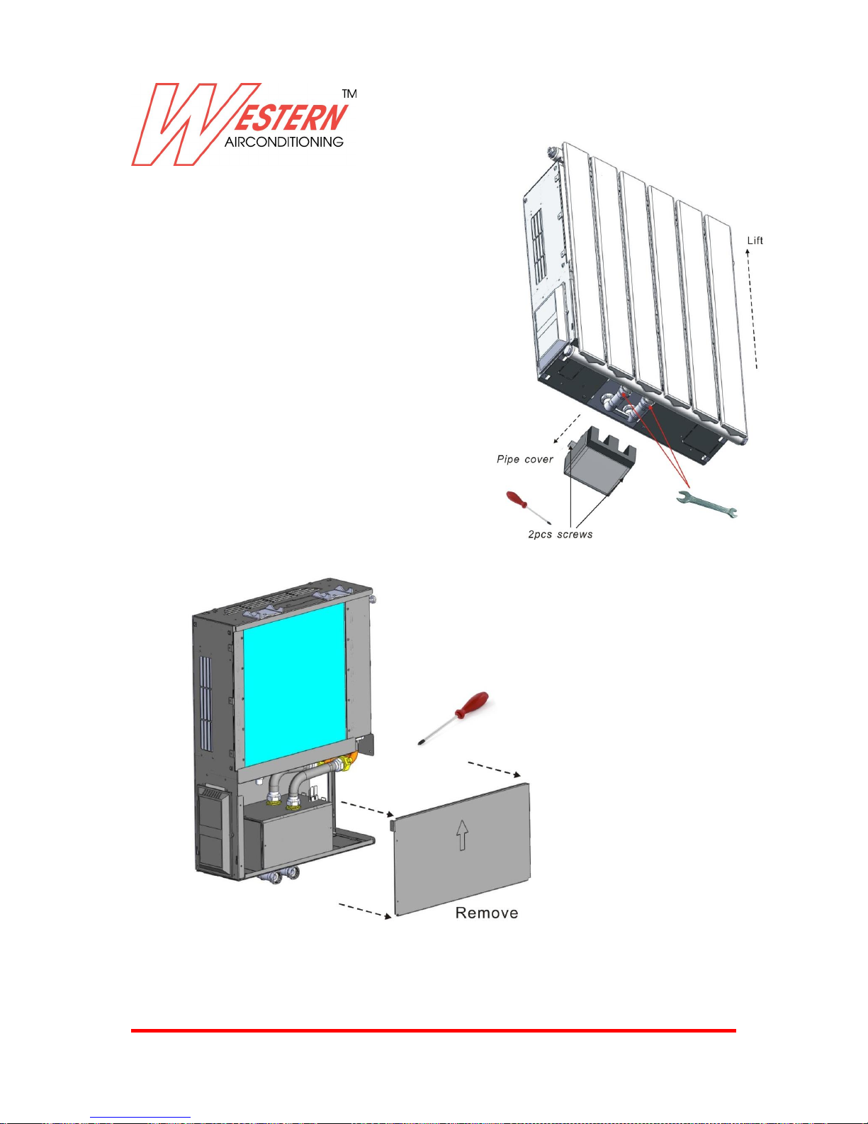
Remove radiator
Take out 2pcs screws by the driver and remove
the pipe cover carefully from bottom of the unit ,
and disconnect the 2pcs radiator nuts with
wrench, then lift the radiator carefully.
Remove metal cover like below image
Page 21
Western Airconditioning B.V. reserves the right to alter specifications
21
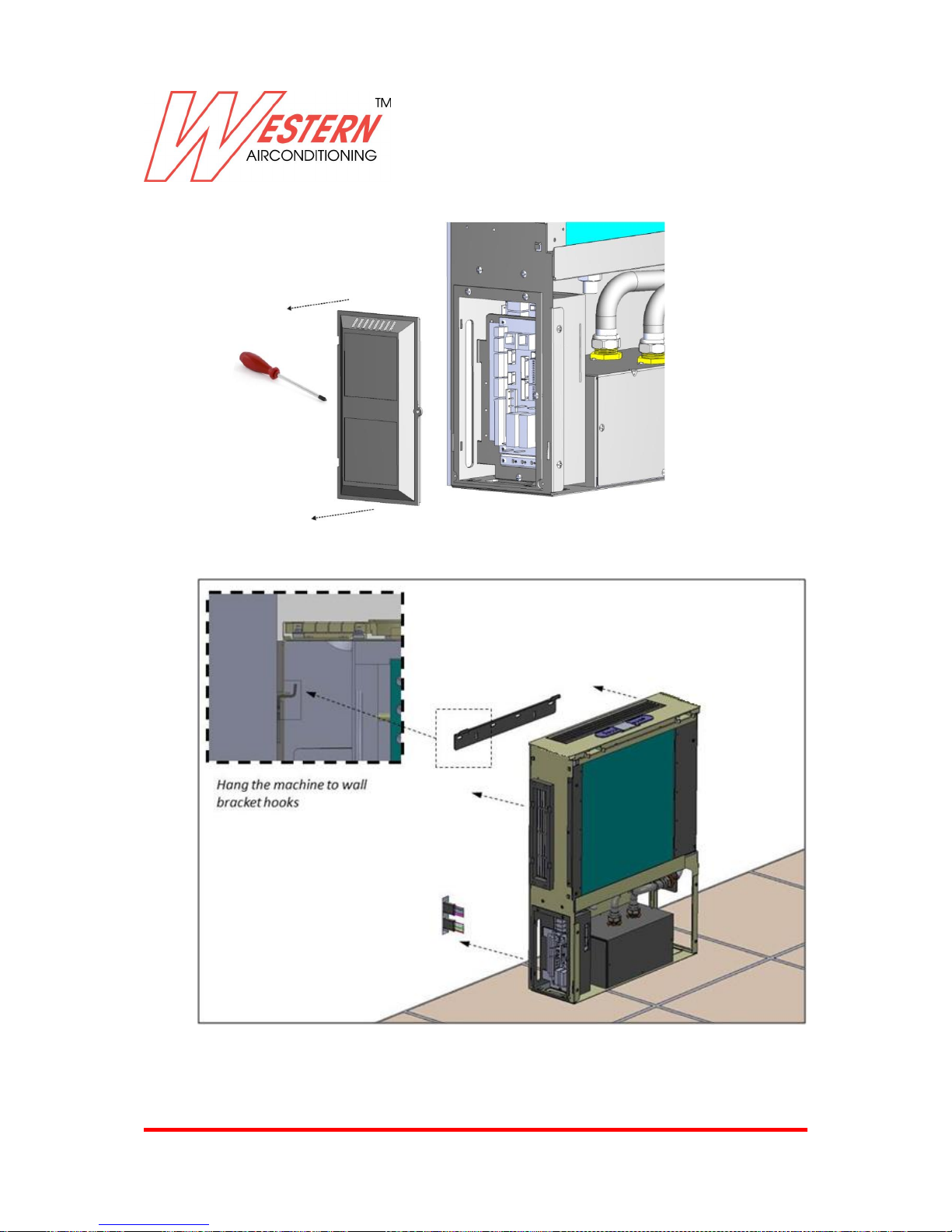
Remove PCB box cover , to have easy access for wiring connection .
Hang the machine to the wall bracket.
Page 22
Western Airconditioning B.V. reserves the right to alter specifications
22
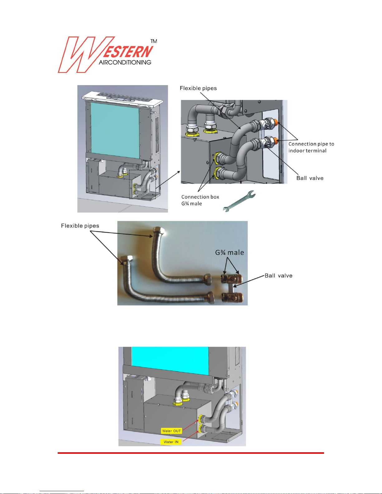
Fix plumbing to the valve box and pay attention to connect IN and OUT pipe in correct position.
Above pipes must be insulating with 6 mm thickness sponge if machine can work also with cold water .
Important Note : Pay attention to connect flexible pipe in right position like below image.
Optional
Page 23
Western Airconditioning B.V. reserves the right to alter specifications
23
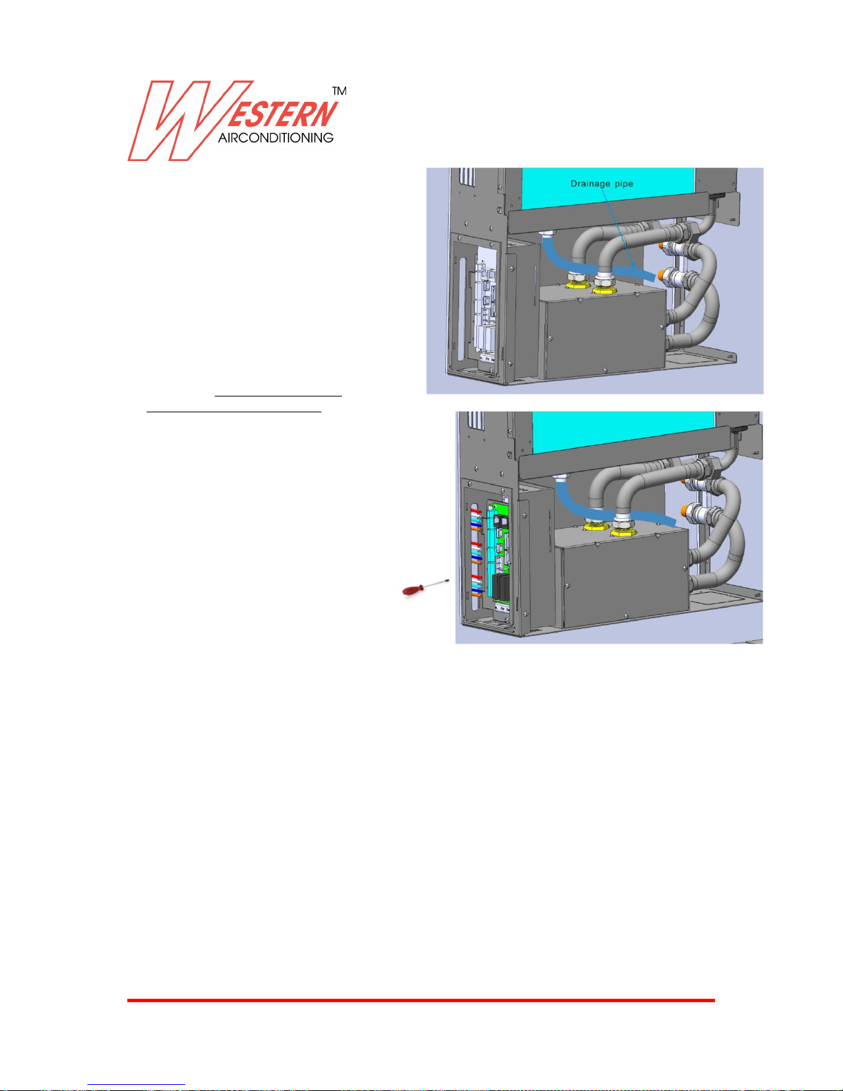
Connect water pipe drainage to the
plumbing discharge like below image .
Proceed to arrange wiring connection
in left side , and pay attention don’t
have electricity inside the wiring
BEFORE AND DURING THE STARTING UP OF THE UNIT (SO WHEN THE UNIT IS ON AND THE VALVE IS
OPENED), VERIFY THE ABSENCE OF WATER LEAKAGE IN ALL PIPES AND HYDRAULIC CONNECTIONS IN
BOTH INTERNAL AND EXTERNAL PART OF THE UNIT
Water side maximum pressure: 600 KPa- ( 6 Bar )
Page 24
Western Airconditioning B.V. reserves the right to alter specifications
24
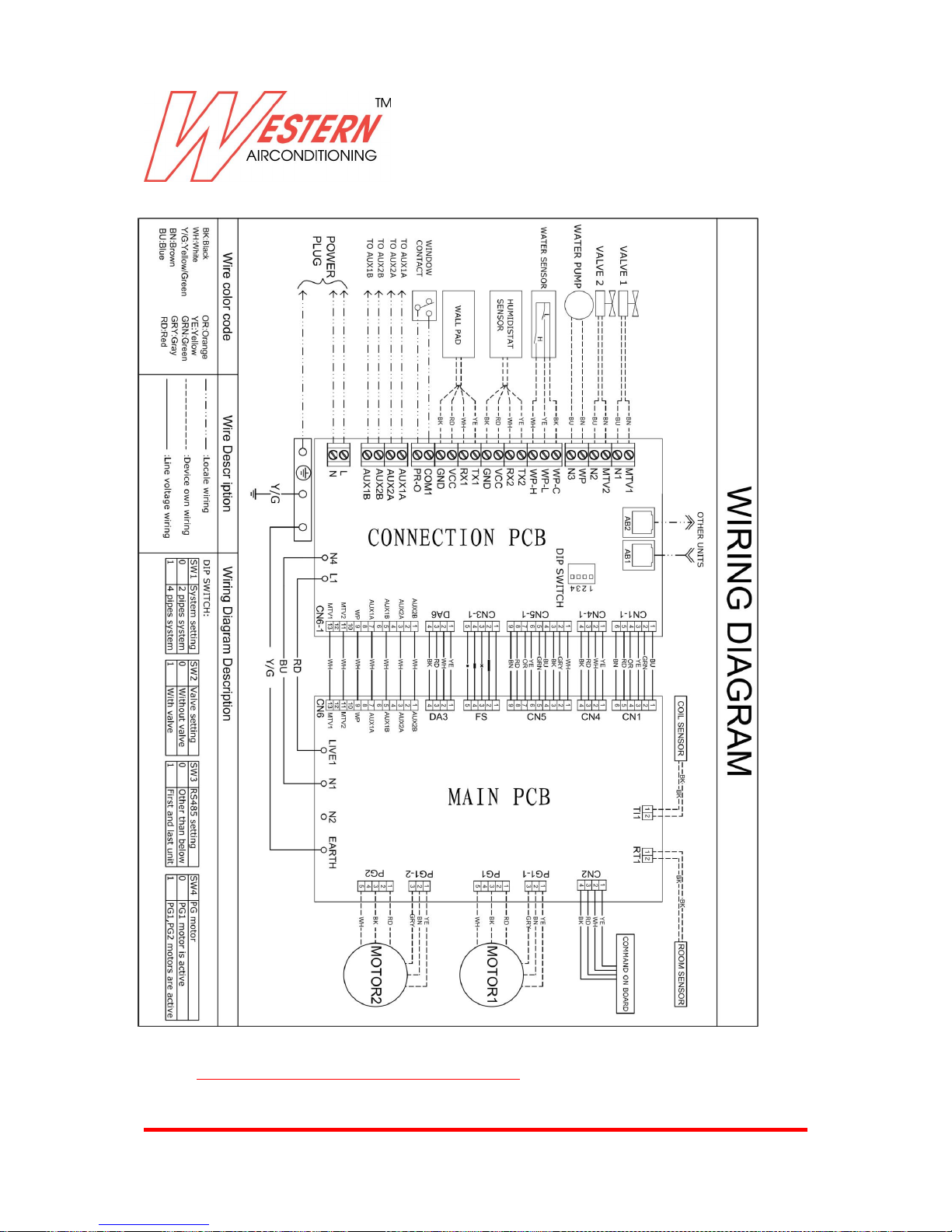
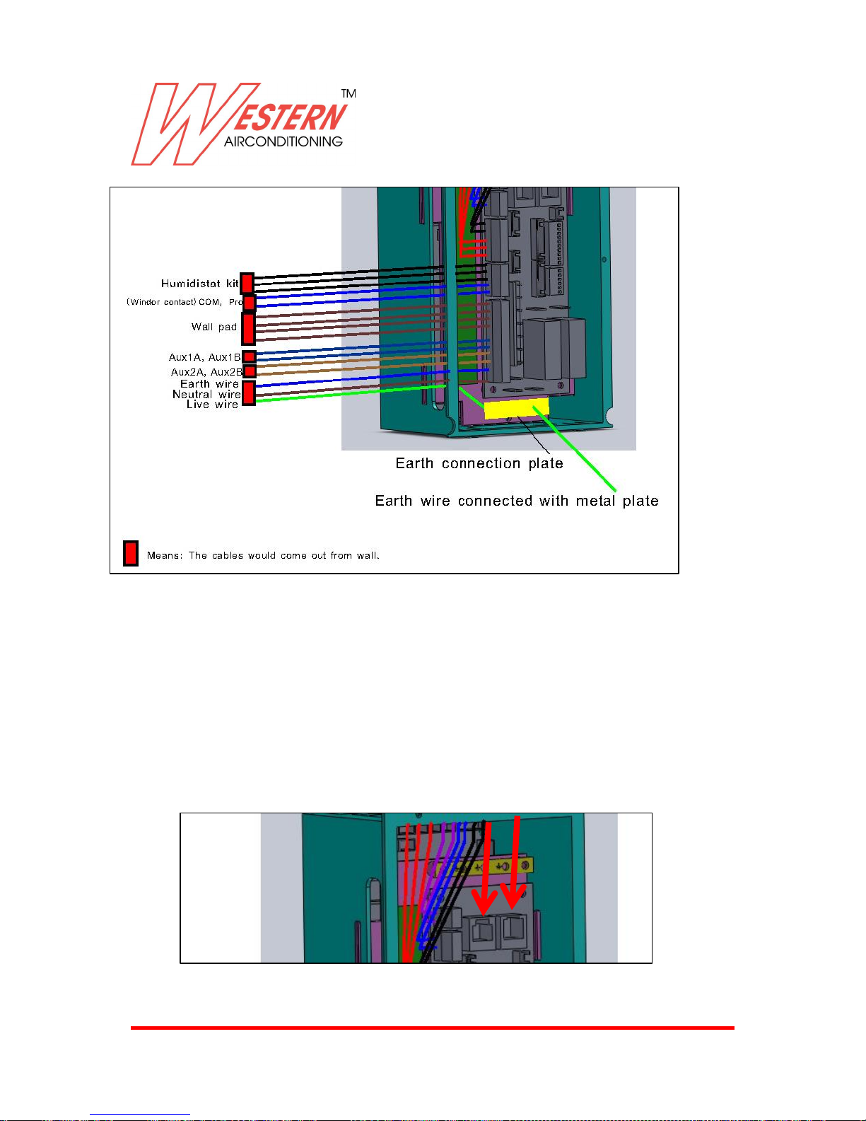
Wiring diagram ( connection PCB )
Pay attention don’t have electricity inside the wiring and proceed to connect power wiring and signal
cables like below scheme.
Page 25
Western Airconditioning B.V. reserves the right to alter specifications
25
Connect GND wiring
Connect N1 Neutral wiring
Connect L1 Phase wiring
Connect wall pad if present
Connect Humidistat Kit if present
Connect Window contact if present
Connect AUX 2 to the Chiller or HP and pay attention this is Cooling NO signal.
Connect AUX 1 to the boiler or HP and pay attention this is Heating NO signal.
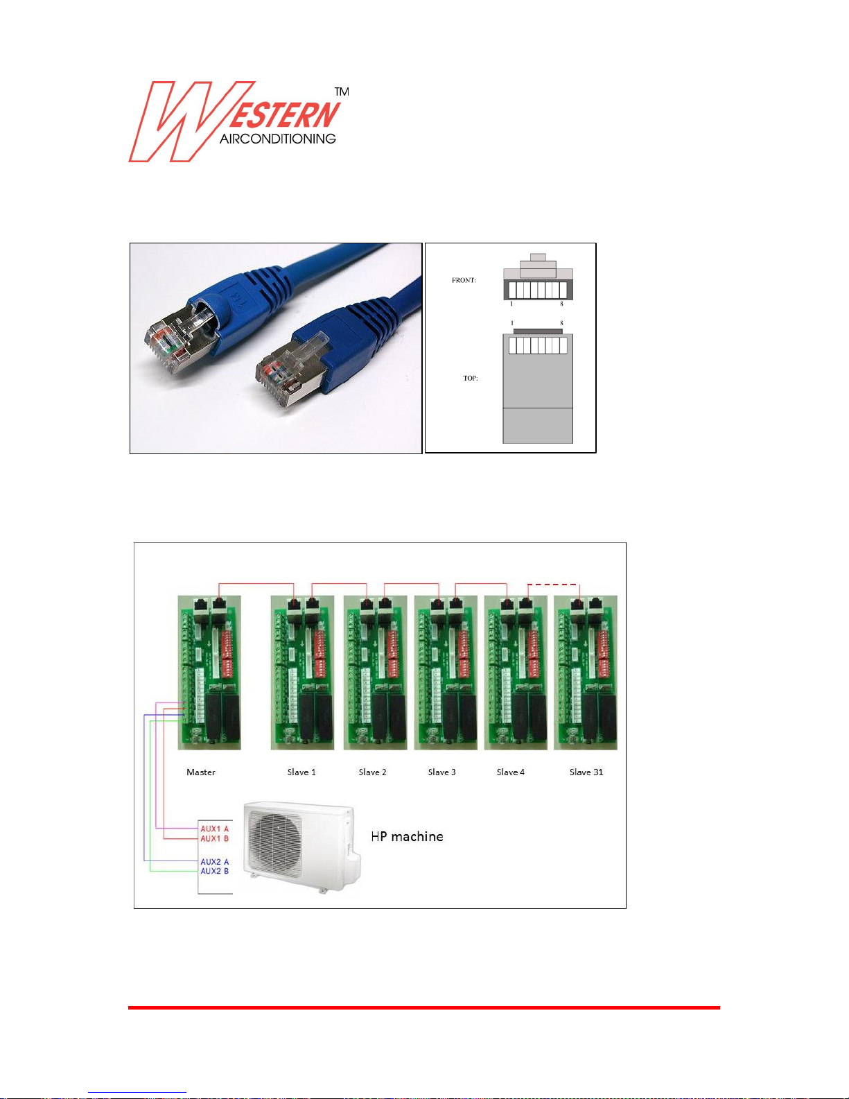
MOD BUS connection .
For master and slave installation , the signal from master unit to slaves units are only from MOB BUS
cable
Page 26
Western Airconditioning B.V. reserves the right to alter specifications
26
Connect MOD BUS plug to RJ45 socket
The MOD BUS plug must be RJ 45 , very common in the market because is used from all computer use
and connection.
See below RJ plug and wiring position ; MOD BUS connection required only two wirings
Below Master & Slave machine connection .
AUX 1 Hot signal
AUX 2 Cold signal
The machine must be configured before used
Page 27
Western Airconditioning B.V. reserves the right to alter specifications
27
Fix PCB box cover
Only when all electric connection are completed , you can proceed with machine configuration like
below procedure .
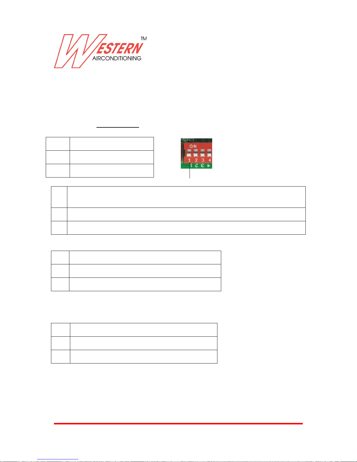
DIP switch setting :
DIP switch setting: 1 for ON, 0 for OFF.
Note: All units will be produced from with SW3= 0 , the installer must remember to set 1 for first and last slave
units to close the net and avoid Net stability problem
Note : SW4 DIP switch will be settled from factory during the production , and is fixed with hot glue to avoid
installer mistake.
SW1
System setting
0
2 pipes system
1
4 pipes system
SW2
MTV(motorized valve) setting [applicable to 2 pipes system only, 4 pipes system is fixed with motorized
valve]
0
Without motorized valve
1
With motorized valve
SW3
RS485 termination setting
0
Other than below
1
First and Last unit on RS485 communication bus
SW4
PG motor
0
PG1 motor is active ( mini size one motor )
1
PG1, PG2 motors are active ( medi size two motors )
Page 28
Western Airconditioning B.V. reserves the right to alter specifications
28
Now you can Supply power electricity to the machine
Switch ON the machine trough On-Off button on command on board .
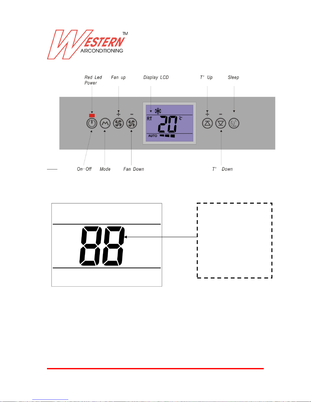
MASTER AND SLAVE ADDRESS SETTING
Press both “FAN UP ” and “MODE” buttons on command on board, and keep 3 seconds, after long beep
from buzzer, unit would come into ID address setting mode.
LCD display show only big number like below image .
Number LED would display the original ID code if it was set before. By pressing Temperature UP/DOWN
buttons to adjust the address code, 02-31 codes mean slave unit, and 01 means master unit.
When you have settled ID code with temperature UP/down buttons, to confirm the ID address you must
push SLEEP button , and after long beep from buzzer , setting is memorized, unit would come back to
normal display.
If there is no any operation after 5 seconds, ID setting is invalid. After long beep from buzzer, LCD would
come back to normal display.
If computer is master unit, 01 master unit should be modified with 32 by manual. As system should have
only one master unit.
01 = master
02 : slave
03 : slave
…
31: slave
32 : slave
Page 29
Western Airconditioning B.V. reserves the right to alter specifications
29
PR PROGRAM SETTING
Press both “MODE ” and “SLEEP” buttons on command on board, and keep 3 seconds, after long beep from buzzer,
unit would come into program setting. Press “Fan+” and “Fan-” buttons to adjust PR1 to PR12, and press “Temp+”
and “Temp-“ to adjust the parameter.
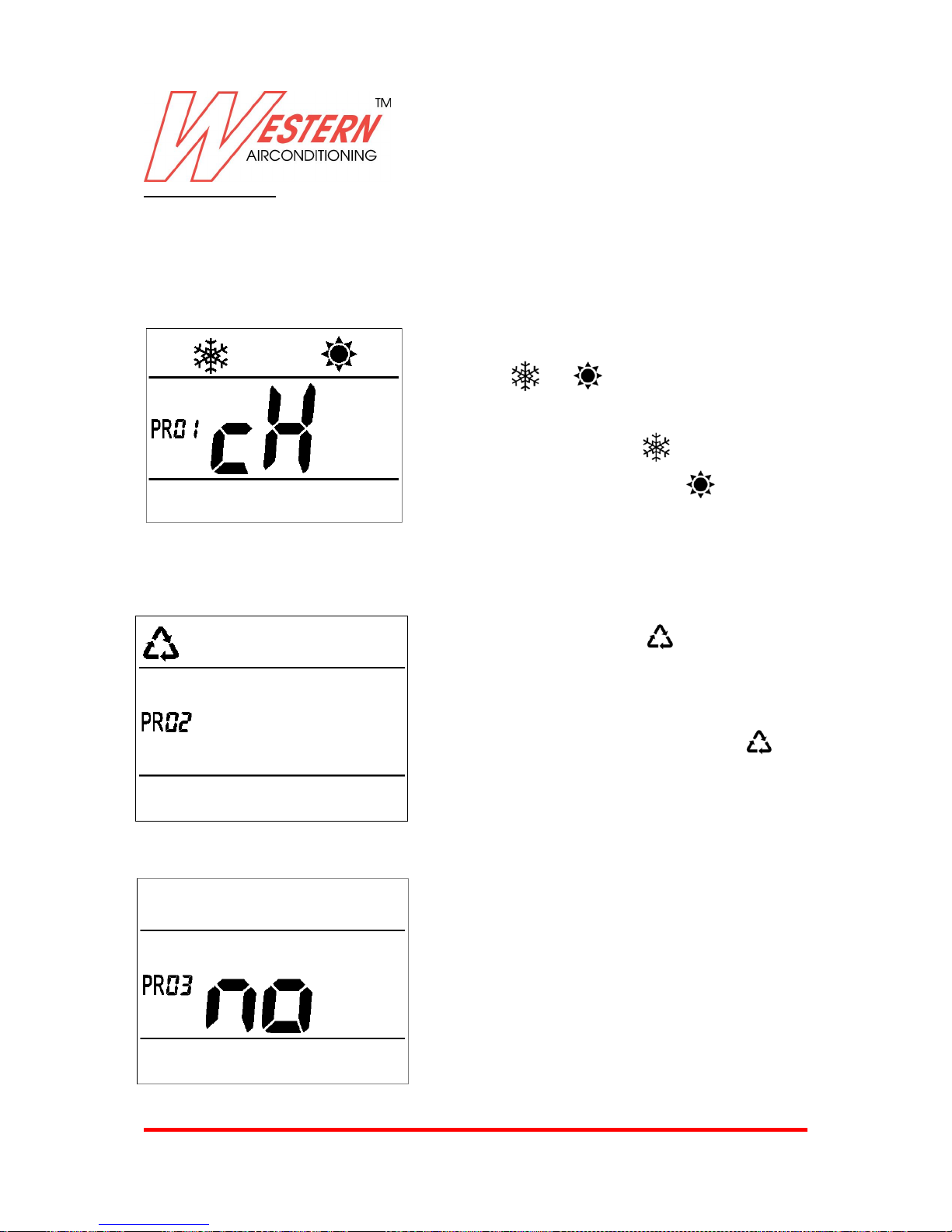
PR 1: Mode setting-Cooling&Heating /cooling / heating setting
When coming in program setting ,the first program showed is PR 01:
PR1: Default setting is Cooling&heating mode, LCD would
display and symbols, and LCD is cH.
Press Temp up or down button, you can select only cooling
mode, LCD would only display , and LED is co. Or only
heating mode, LCD would only display , and LCD is hE.
After PR1 mode setting, pressing Fan up button to enter PR2.
PR 2: AutoMode
PR2: Auto mode like below :
Default configuration is symbol on = Auto mode is on
and machine work with specific program for each type of
configuration settled before , with and without valve , 2
pipes or 4 pipes .
Press Temp up or down buttons to select symbol off =
Auto mode is off .
After PR2 setting, press Fan up button to enter PR3.
PR3: Alarm with or without buzzer
PR 3: Default configuration LCD is “no” = Buzzer OFF for
Alarm. When there is problem with unit, LCD will display
error code only.
Press Temp up or down buttons, to adjust LCD with
“nc”=Buzzer ON for Alarm. When there is problem with
unit, LCD will display error code, same time buzzer is ON all
the time.
PR3 is only for Alarm setting, PCB would responds “beep”
once receiving the commands all the time.
After PR3 setting, press Fan up button to enter PR4
Page 30
Western Airconditioning B.V. reserves the right to alter specifications
30
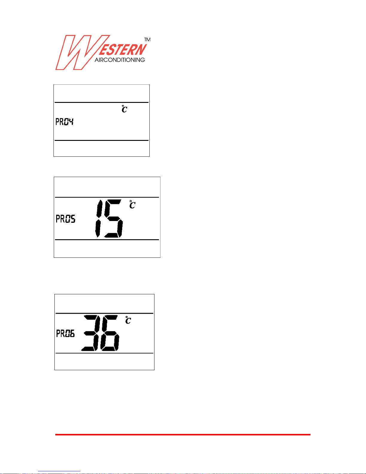
PR 4= Celsius and Fahrenheit conversion
PR 4: Default display is °C symbol. Press Temp up or down
button to set °C or °F.
Note : in Program PR 4 , show only °C or °F.
After PR4 setting, press Fan up button to enter PR5.
PR 5 = Anti-hot air setting in cooling mode
PR5 is cold water temperature setting for anti-hot air
function during cooling mode, default value is 15 if °C is
settled and display. Or default value is 59 if °F is settled and
display.
Press Temp up or down button to change this value
conforming to below range :
°C setting: 7-30.
°F setting: 45-86.
Note : in Program PR 5 , no possible to set number out of above range 7-30 for °C range and 45-86 for °F range
After PR5 setting, press Fan up button to enter PR6.
PR 6 = Anti-cold air setting in heating mode
PR6 is hot water temperature setting for anti-cold air
function during heating mode, default value is 36 if°C is
settled and display. Or default value is 97 if °F is settled
and display. Press Temp up or down button to change this
value conforming to below range :
°C setting: 25-45.
°F setting: 77-113.
Note : In Program PR 6, no possible to set number out of above range 25-45 for °C range and 77-113 for °F
range.
As the LCD only could display 99 with the max number, for other numbers, like 100-113, it would show a0,
a1….a9, b0, b1….b3 accordingly.
After PR6 setting, press Fan up button to enter PR7
Page 31
Western Airconditioning B.V. reserves the right to alter specifications
31
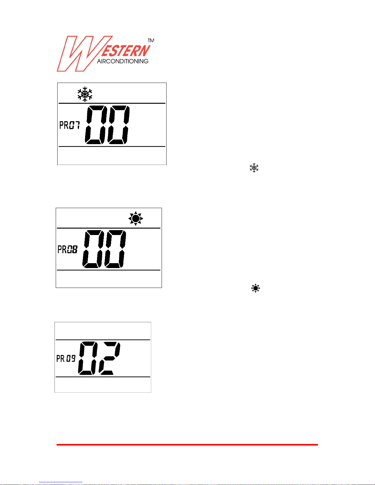
PR 7 = Setting temperature range in cooling
PR7: Need to set different temperature range with cooling
mode. Default range is 16-30 ℃ (61-86℉) and LCD display 00.
Other 3 settings are optional: 01,02,03
01: 20-30℃(68-86℉)
02: 23-30℃(73-86℉)
03: 25-30℃(77-86℉)
Press Temp up or down button to select the setting. In PR7, only show cooling symbol , and LCD show
00,01,02,03.
After PR7 setting, press Fan up button to enter PR8.
PR 8 = Setting temperature range in heating
PR8: Need to set different temperature range with heating
mode. Default range is 5-30 ℃ (41-86℉) and LCD display 00.
Other 3 settings are optional: 01,02,03
01: 5-25℃(41-77℉)
02: 10-25℃(50-77℉)
03: 15-25℃(59-77℉)
Press Temp up or down button to select the setting. In PR7, only show heating symbol , and LCD show
00,01,02,03. After PR8 setting, press Fan up
button to enter PR9.
PR 9 = NTC compensation in cooling mode
PR9:Neet to set NTC compensation in cooling mode. Default
compensation is +2 for °C setting, LCD display 02. Press Temp
up or down button to change this value conforming to below
range: -3-+3. Or default compensation is +4 for °F setting, LCD
display 04, and range is -6~+6.
Note : in Program PR9, no possible to set number out of
above range -3-+3.
After PR9 setting, press Fan up button to enter PR10.
PR9 should be set by factory, and would be invalid for the wall pad NTC. This setting is invalid for wall pad NTC
sensor.
Page 32
Western Airconditioning B.V. reserves the right to alter specifications
32
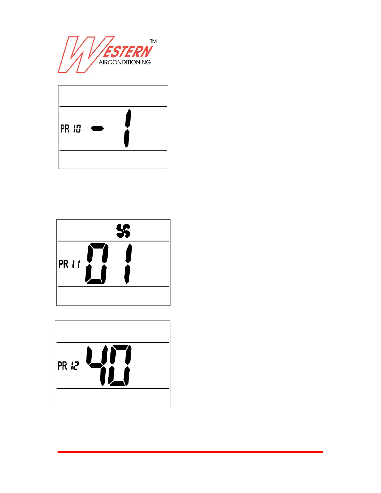
PR 10 = NTC compensation in heating mode
PR10: Need to set NTC compensation in heating mode.
Default compensation is -1, LCD display -1. Press Temp up
or down button to change this value conforming to below
range: -4-+4.
Note : in Program PR10, no possible to set number out of
above range -4-+4.
After PR10 setting, press Fan up button to enter PR11.
PR10 should be set by factory, and would be invalid for the wall pad NTC.
This setting is invalid for wall pad NTC sensor.
PR 11 = Fan speed selection
PR11: Need to select fan speed. Default fan speeds are 850800-700-600-550-500rpm, and LCD display 01.
Another option is:
02: 650-600-550-500-450-400rpm
Press Temp up or down button to select the setting, In
PR11, LCD only shows 01,02.
After PR11 setting, press Fan up button to enter PR12.
PR 12 = Time setting of Anti-hot air/Anti-cold air
PR12: Need to select the setting time of anti-hot air during
cooling mode, or anti-cold air during heating mode. PR12
setting is suitable for both Anti-hot air and Anti-cold air
time setting. Default setting time is 40 minutes, and LCD
display 40.
Press Temp up or down button to change this value
conforming to 1-90 minutes range.
In PR12, no possible to set number out of the range 1-90.
After PR setting is finished, press both “MODE” and “SLEEP” buttons for 3 seconds, system would remember
the setting and exit PR setting program.
Page 33
Western Airconditioning B.V. reserves the right to alter specifications
33
PR DEFAULT SETTING
Press both “MODE ” and “FAN -” buttons on command on board, and keep 3 seconds, after long beep from
buzzer, all PR setting(PR1-PR12) would be with default status.
Below is default PR setting
PR No.
PR Setting
Default condition
PR1
Mode setting-Cooling&Heating /cooling /
heating setting
Cooling&Heating, LCD display cH
PR2
Auto Mode setting
Yes, LCD display
PR3
Alarm with or without buzzer
No, LCD display “no”
PR4
Celsius and Fahrenheit conversion
Celsius, LCD display “℃”
PR5
Anti-hot air setting in cooling mode
15℃ or 59℉
PR6
Anti-cold air setting in heating mode
36℃ or 97℉
PR7
Setting temperature range in cooling
16-30 ℃ (61-86 ℉) , LCD display “00”
PR8
Setting temperature range in heating
5-30 ℃ (41-86 ℉), LCD display “00“
PR9
NTC compensation in cooling mode
+2,LCD display “02”
PR10
NTC compensation in heating mode
-1, LCD display “-1”
PR11
Fan speed selection
850-800-700-600-550-500rpm,LCD display
01,
PR12
Time setting of Anti-hot air/Anti-cold air
40minutes, LCD display 40
Page 34
Western Airconditioning B.V. reserves the right to alter specifications
34
4.6 FIX RADIATOR, COVER AND ALL THE METAL SHEET.
Machine hardware and software configuration is terminated , now we can proceed to fix the frontal radiator
and switch ON the system .
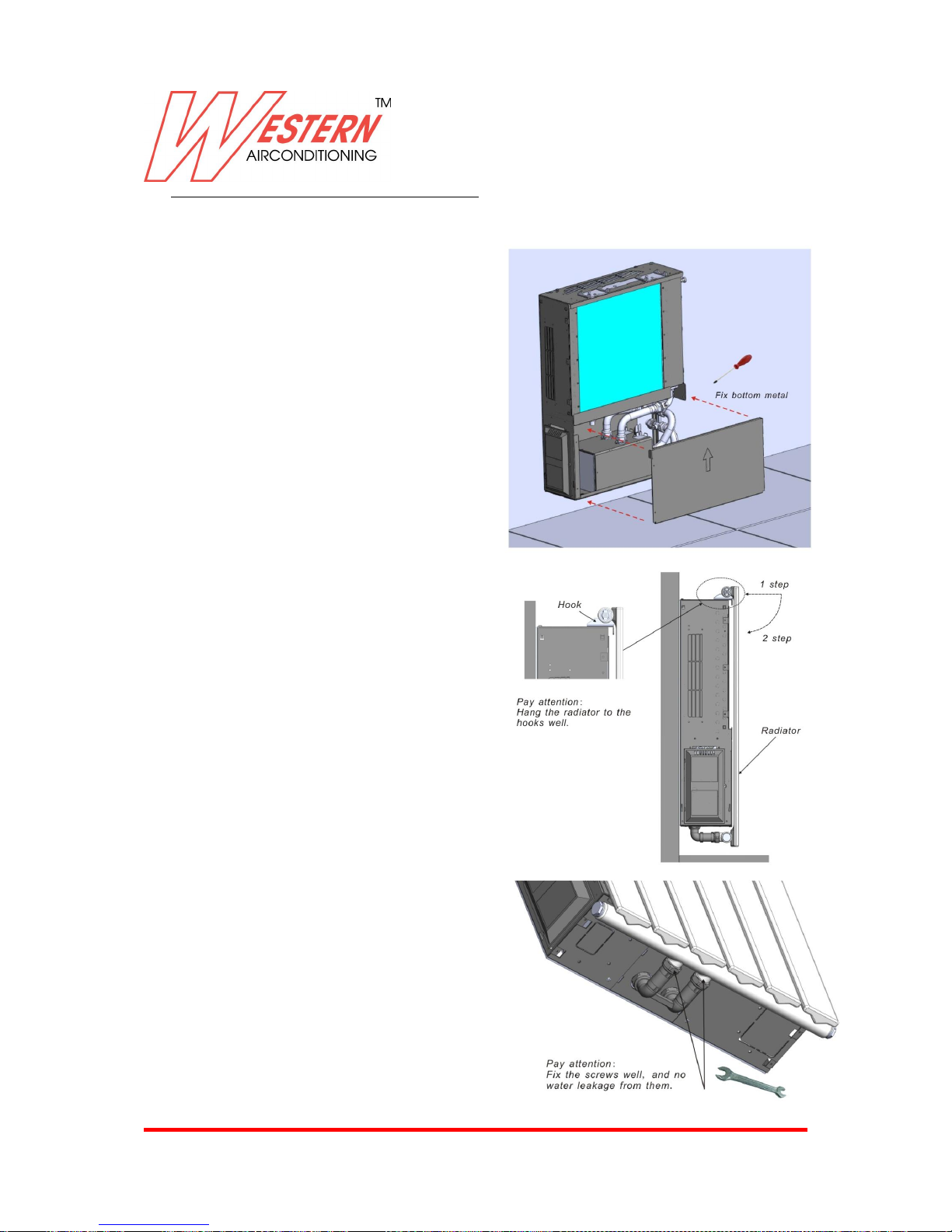
Fix radiator in front of the machine :
After PCB connection , we can proceed to
finish machine installation .
Proceed to close frontal metal cover like
right image .
Proceed to hang radiator to the machine
hooks:
Connect radiator pipes in the machine bottom:
As the connector is in the bottom, just be with
some patient, connect the pipe well.
No need insulating these pipes because
every time work with hot water .
Now, we can check the water system, if there
Is leakage.
Page 35
Western Airconditioning B.V. reserves the right to alter specifications
35
Fix pipe cover
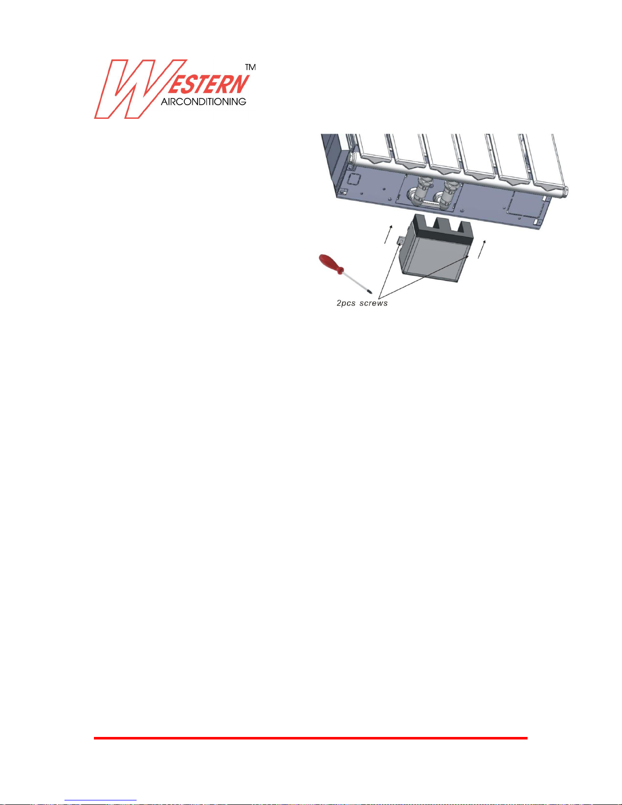
If there is no water leakage, we should fix the
pipe cover at the bottom of the unit.
Push the pipe cover and insert the buckle into
the metal case holes.
Fix 2pcs screws by driver.
As the cover is in the bottom, just be with
some patient, connect the pipe well.
Fix panel on the top of the machine
Repeat reverse operation as indicated in the previous pages to remove the panel on the top.
Note: Connect the display cable and fix it well.
Note: before fixing the right flank to the unit, access to air vent and water purge as indicated in the next
section
Fix left&right flanks on the machine
Repeat reversed operations as indicated in the previous pages to remove the metal painted flanks
PRELIMINARY CHECKS BEFORE START-UP
Open water circuit and deeply check don’t have any water leakage, we remember if fan coils will be
used with chilled water, connection pipe must be insulating .
The unit should not be started up until the system piping has been cleaned and remember all the air has
been purged (if you don’t make operation as indicated before).
Page 36
Western Airconditioning B.V. reserves the right to alter specifications
36
4.7 HOW TO ACCESS AIR VENT AND WATER PURGE
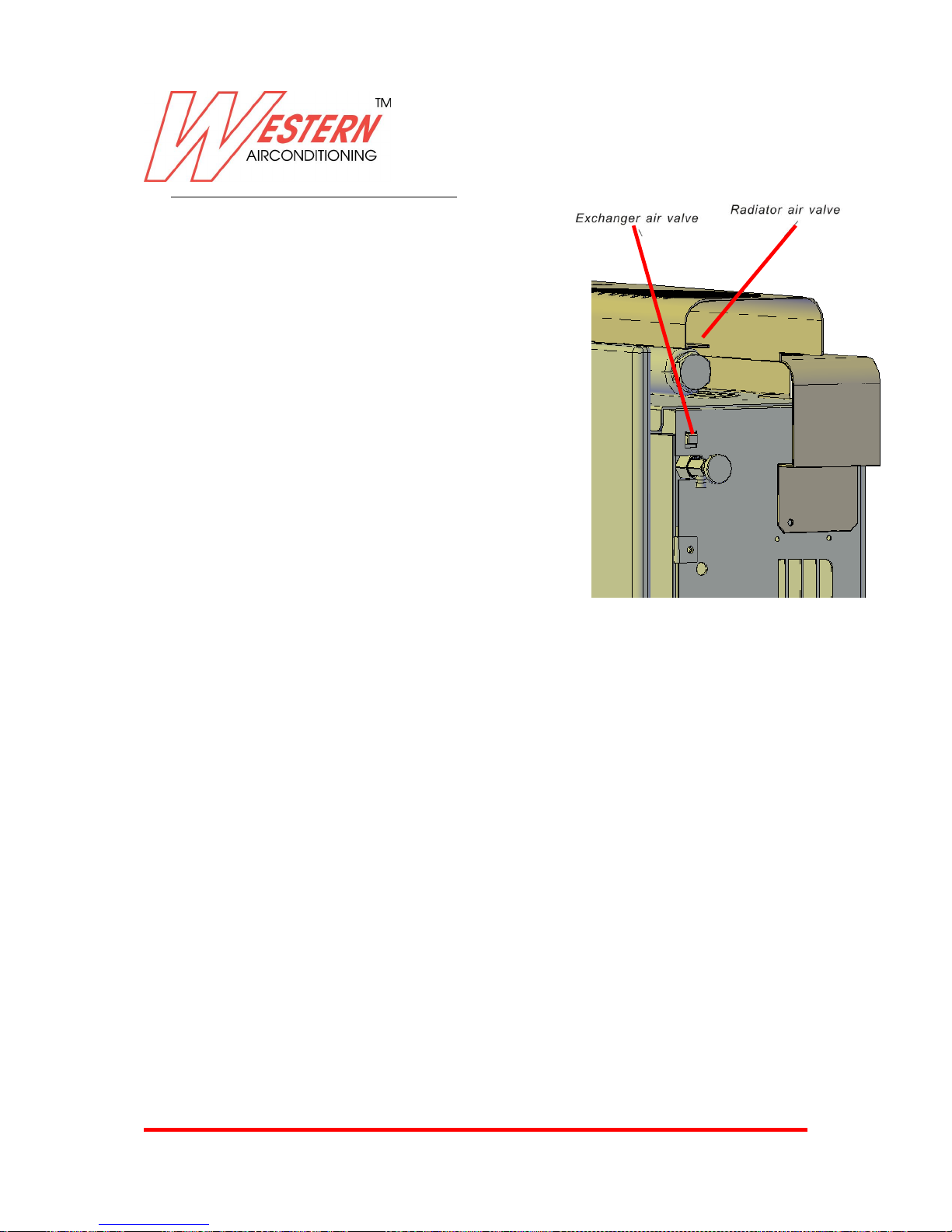
Remove the flank on the right as indicated
In the previous pages
(you are in front of the radiator).
1st STEP: there are two air purge:
one is for the radiator,
another is for the exchanger.
2nd STEP: release the water purge
like traditional radiator with loosing the
screws by hand.
EVACUATING AIR WHILE FILLING THE SYSTEM
Open all the system device ( automatic or manual ) .
Start the filling by slowly opening the system water filling tap .
For the 2- pipes version , set the machine in heating mode and when the water coming out of the valves of
the appliance , close them and continue filling until reaching the nominal value for the system .
Check the hydraulic seal of the gasket .
It is advisable to repeat these operations after the appliance has been running for a few hours and
periodically check the pressure of the system .
For the 4-pipes system , use above procedure in cooling and heating mode .
Check condensate drain pipe slope.
After you have connected the main power supply to the unit, it is necessary to check the good function of
the condensate water pump which is installed inside. Due to transport vibration, it might be possible that
the float switch is hung up and the pump might not work in the correct way. For this reason, you have to
do the following, to ensure good functioning of the unit:
Install the unit in an absolute horizontal position.
Fill the internal drain pan (manually) with enough water to ensure the drain pump is working.
Make sure that air filter is clean and properly installed.
Verify that air outlets are not closed.
If all preliminary check is OK , you can proceed to assembly missing parts , like
Filter
Air purge rubber cover
Radiator pipe cover
Page 37
Western Airconditioning B.V. reserves the right to alter specifications
37
5. ADDITIONAL INFORMATIONS
Below is reported the list of accessory and some important technical information for their installation and
correct use .
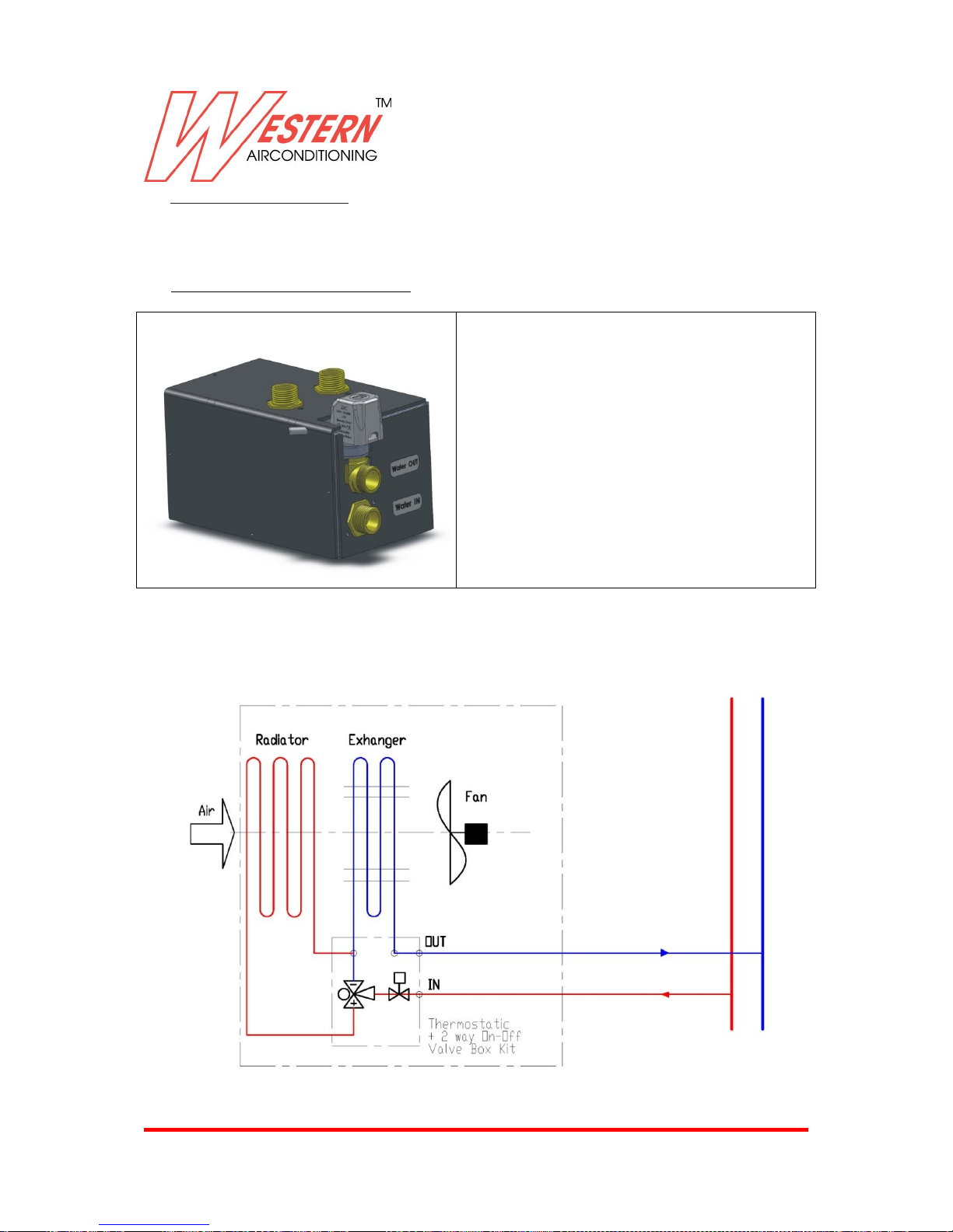
5.1 THERMOSTATIC+2 WAY VALVE BOX KIT
Installation : 2 pipes ( hot and Cold water )
Thermostatic valve default setting 30 °C
This valve box , need to activated radiator only
when water temperature is higher than 30 °C .
2 way valve with ON-OFF actuator
This valve box is suggested when present
Inverter pump in the hydraulic circuit
Below hydraulic scheme .
Hydraulic scheme
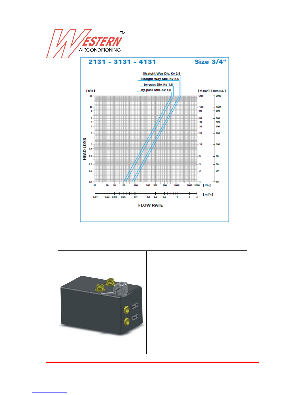
Characteristic curve of Watts Industries Valve used (see “straight way Kv 2.8”)
Page 38
Western Airconditioning B.V. reserves the right to alter specifications
38
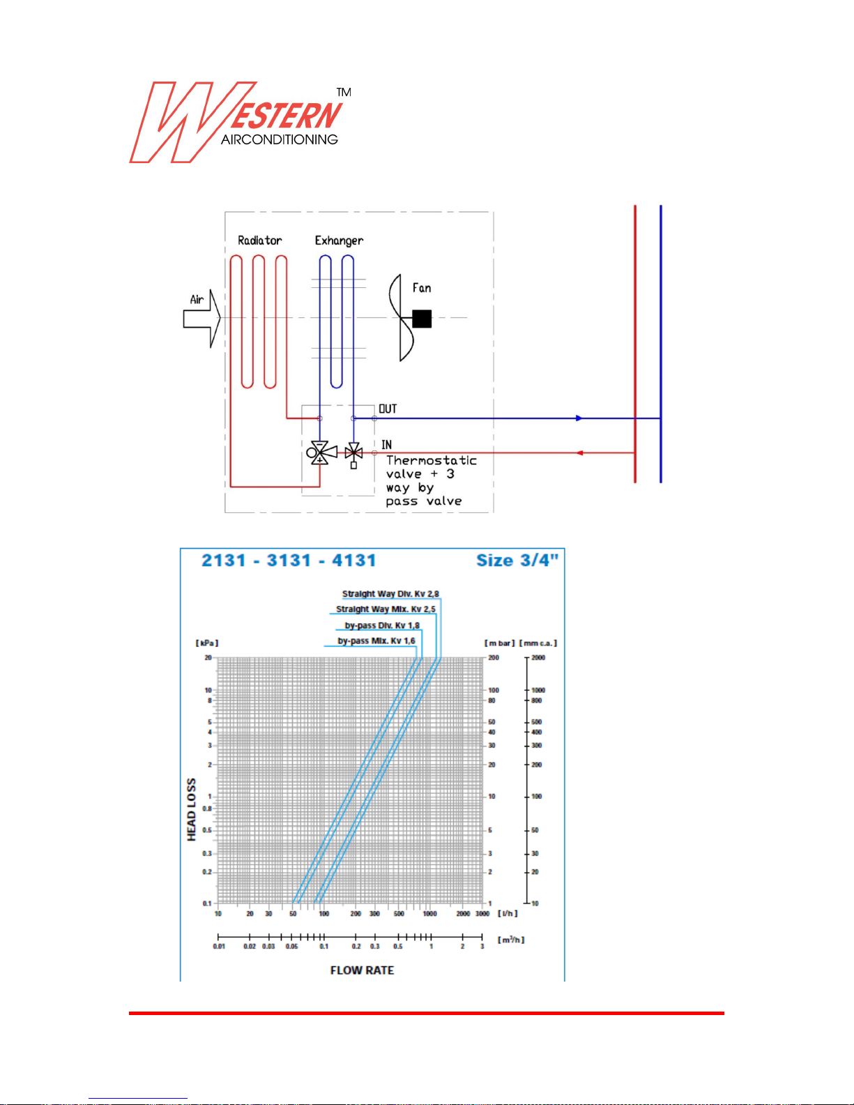
5.2 THERMOSTATIC +3 WAY BY PASS VALVE BOX KIT
Installation : 2 pipes ( hot and
Cold water ).
Thermostatic valve default
setting 30 °C.
This valve box , need to activated
radiator only when water
temperature is higher than 30 °C.
3 way by pass valve with ON-OFF
actuator.
This valve box is suggested when
present On-Off pump in the
hydraulic circuit.
Below hydraulic scheme.
Page 39
Western Airconditioning B.V. reserves the right to alter specifications
39
Hydraulic scheme
Characteristic curve of Watts Industries Valve used (see “straight way Kv 2.8” and “by-pass KV 1.8”)
Page 40
Western Airconditioning B.V. reserves the right to alter specifications
40
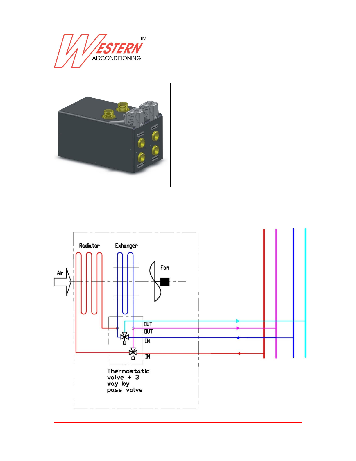
5.3 4-PIPES 3 WAY BY PASS VALVE BOX KIT
Installation : 4 pipes ( hot and Cold
water )
This valve box , need to activated
radiator only when unit is working with
heating mode.
3 way by pass valve with ON-OFF
actuator
This valve box is suggested for On-Off
and Inverter pump in the hydraulic
circuit
Below hydraulic scheme .
Hydraulic scheme
Page 41
Western Airconditioning B.V. reserves the right to alter specifications
41
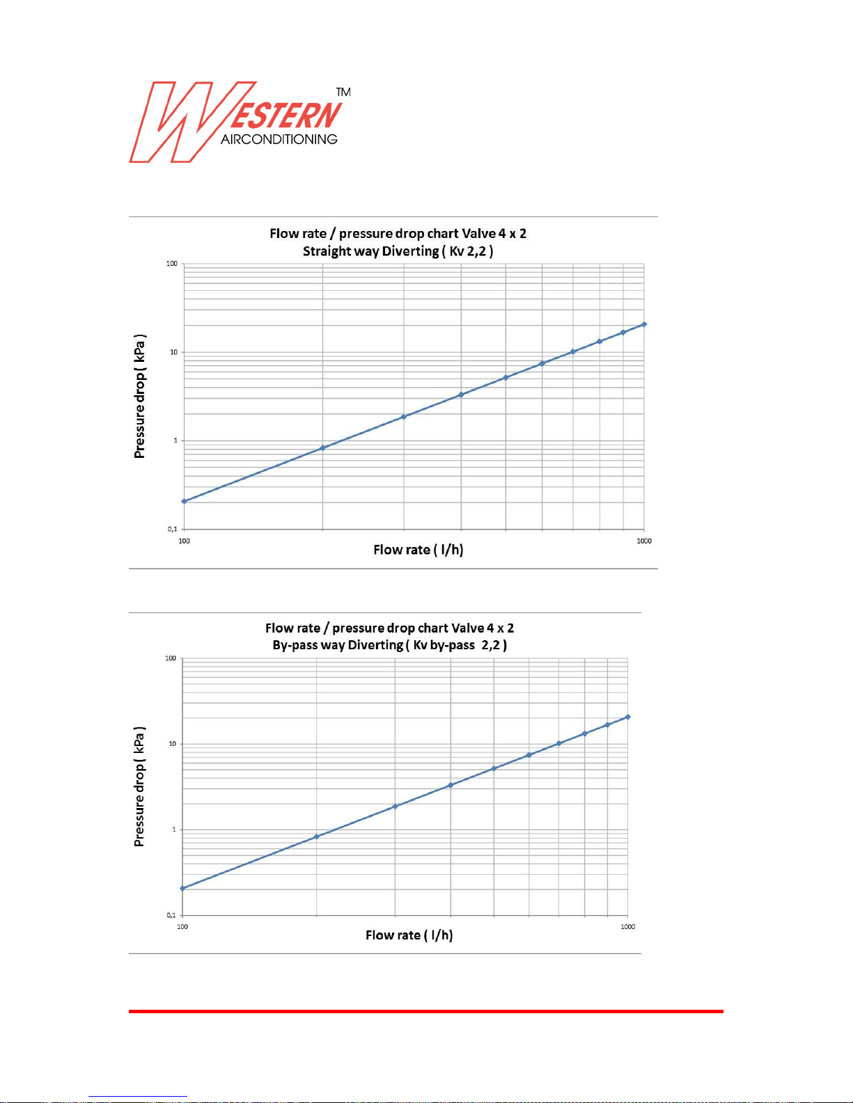
Characteristic of Watts industries Valve used
Page 42
Western Airconditioning B.V. reserves the right to alter specifications
42
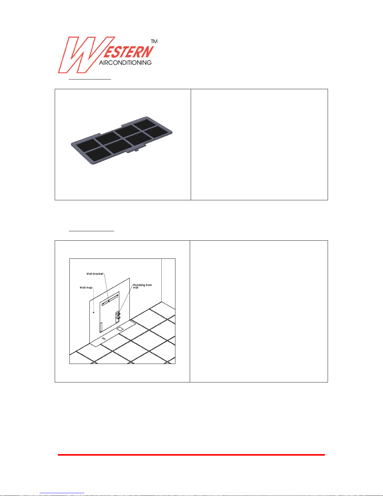
5.4 CATALITIC FILTER
Catalytic filter
This filter must be changed every 100
h , not possible to clean .
5.5 METAL WALL MAP
Strong and adapt for many installation
Page 43
Western Airconditioning B.V. reserves the right to alter specifications
43
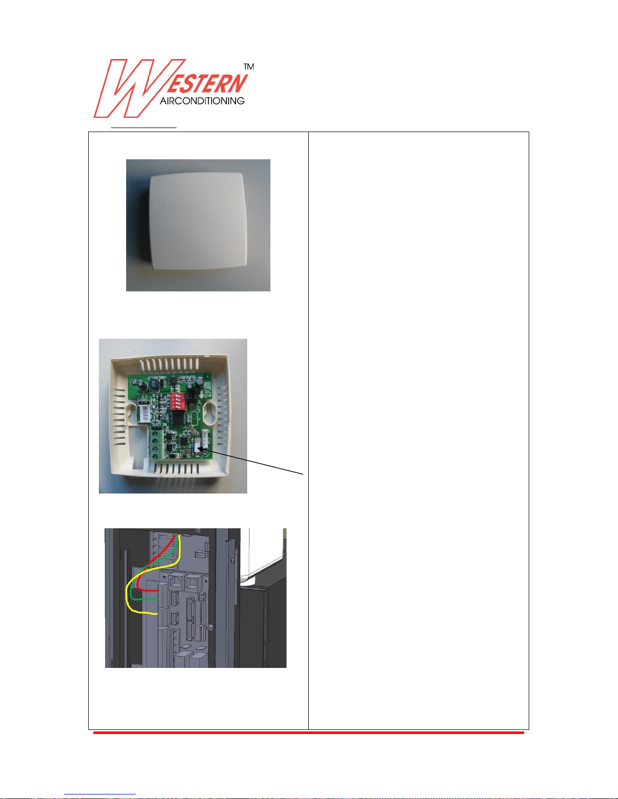
5.6 HUMIDISTAT KIT
Procedure to install Humidity kit
Humidistat kit , to control humidity
inside the room to prevent moisture
on the floor or radiant surface
Decide the right location for sensor
box and fix back box to the wall with
anchors.
This white sticker is protecting the
sensor when this kit is not used, just
remove it.
Only master unit should be
connected to Humidistat kit .
Proceed to arrange connection inside
to the PCB box.
Red cable: VCC, Black cable: GND,
White cable: RX2, Yellow cable: TX2
The machine recognize automatically
the component , and when machine
work in Dehumidification Mode will
use humidistat kit .
Page 44
Western Airconditioning B.V. reserves the right to alter specifications
44
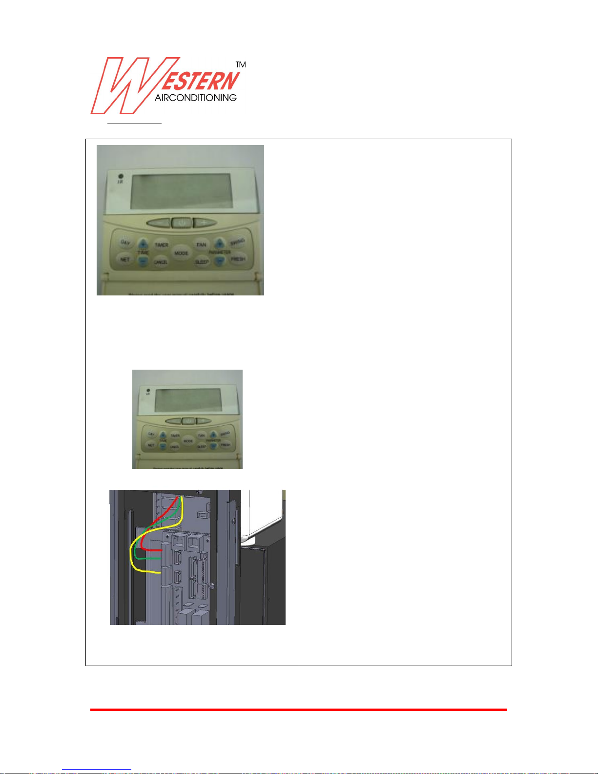
5.7 WALL PAD KIT
Procedure to install
Wall pad , to control all machine
functionality for global control
Decide the right location for sensor
box and fix back box to the wall with
anchors .
If wall pad is connected to master
unit it control all the net ( master and
slave ) and wall pad is master .
If wall pad is connected to slave
control only slave unit
Proceed to arrange connection inside
to the PCB box .
Red cable: VCC, Black cable: GND,
White cable: RX1, Yellow cable: TX1
The machine recognize automatically
the component
For function see below information
Page 45
Western Airconditioning B.V. reserves the right to alter specifications
45
6. NOTE FOR THE FINAL CUSTOMER AND MAINTENANCE
LCD COMMAND ON BOARD
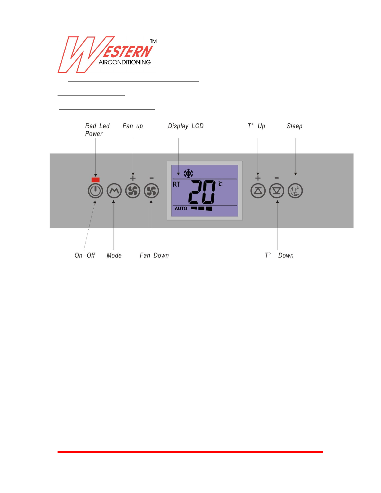
Description Of LCD Command On Board
Red Led Power: Electrical power connection Signal.
ON/OFF: Turn ON or Turn off the unit.
Mode: Set up the unit operating mode.
Fan up: Increase the fan speed.
Fan down: Decrease the fan speed.
Temperature up: Increase the setting temperature.
Temperature down: Decrease the setting temperature.
Sleep: Automatically adjusting the setting temperature according the circadian rule.
Temperature sensor: Check the room temperature.
Page 46
Western Airconditioning B.V. reserves the right to alter specifications
46
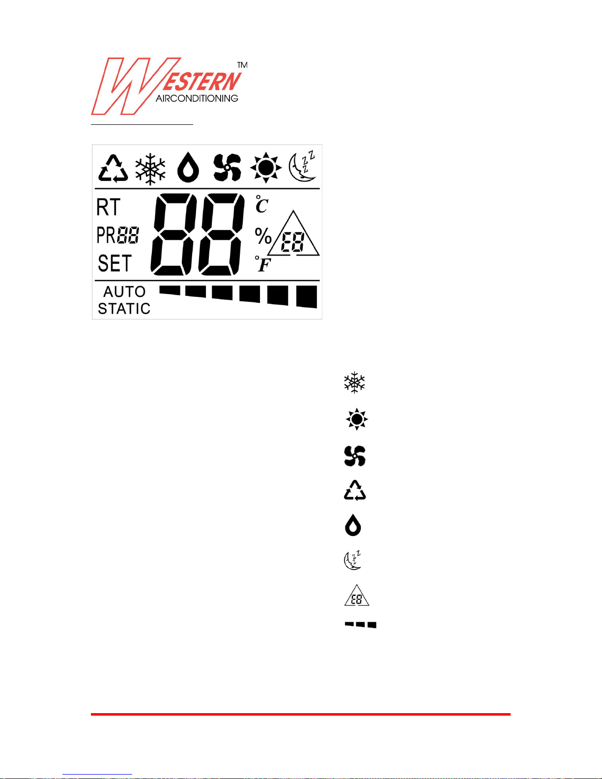
Description Of Display LCD
Symbols :
( ) : Cooling mode
( ) : Heating Mode
( ) : Fan Mode
( ) : Auto Mode
( ) : Dehumidification Mode
( ) : Sleep Mode
( ): Alarm ( from E1 to E11 )
( ): Fan speed (from 1 to 6)
Legenda :
RT : Room temperature
SET : Setting temperature
°C : Celsius temperature
°F : Fahrenheit temperature
%: Humidifity display
Fan : 6 fan speeds
Auto: Auto fan speed
Static : No fan speed(only within heating
mode)
PR88: Program mode, PR01-12(program
setting purpose)
Page 47
Western Airconditioning B.V. reserves the right to alter specifications
47
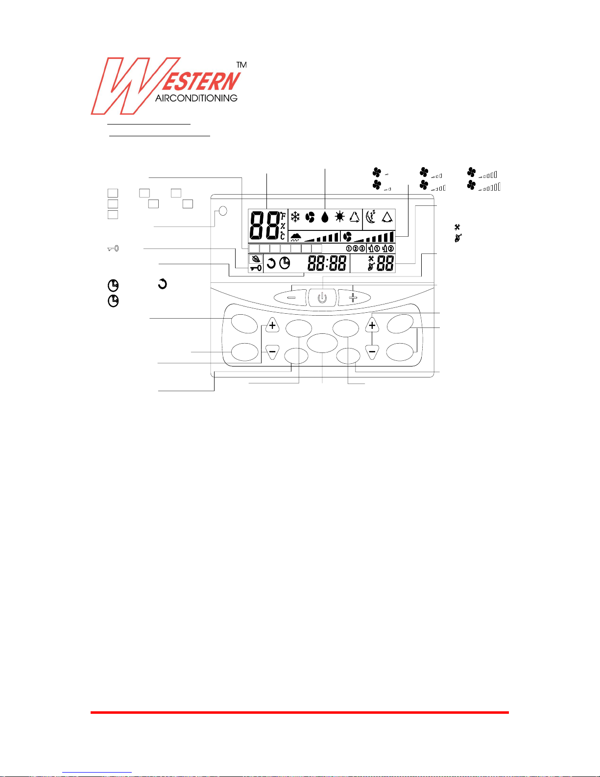
EXCLUSIVE WALL PAD
Exclusive Wall Pad Display
GROUP
SLEEP
MODE
TIME
NET
DAY
CANCEL
TIMER
FAN-
FAN+
HUMIDIFY
HUMIDIFY
AUTO
HEATER
SUN MON TUE WED THU FRI SAT
OFF
ON
ERR
UNIT
HEATCOOL FAN DRY SLEEP
AUTO
SWING
Temperature display area
Display set or room temperature
Operation display
fan 1
fan 2
fan 3
fan 4
Fan speed display
Day display area
Display day of week
SUN
Sunday
Monday
MON TUE
Tuesday
Friday
FRI
THU
Thursday
Wednesday
WED
Saturday
SAT
Key lock
Timer display area
Display on/off timer or real time cl ock, RTC
ON
On timer
OFF
Off timer
Global control
by master in
networking mode
Unit display area
Display Unit address
ERR
Error display
UNIT
Address display
On/Off button
Press once to start operation
Press again to stop operation
Room temperature setting button
Net button for networking control
Day button
To select day of week, Sunday to Saturday
Or used in weekly on/off timer
programming to select day of week
global control mode setting
and sleep
Time setting button
To adjust the RTC setting or to be used in
on/offtimer programming to adjust timer setting
Timer cancel button
To cancel on/off timer setting in
timer programming mode
Timer button
Press to activate on/off
timer programming mode
IR
Infra red reception
To receive wireless handset signal
Mode button
Press to select cool,
fan, dry, heat or
auto operation mode
Fan speed minu button
Fan speed add button
Humidify + and - buttons to select slave unit
fan 5
fan 6
Page 48
Western Airconditioning B.V. reserves the right to alter specifications
48
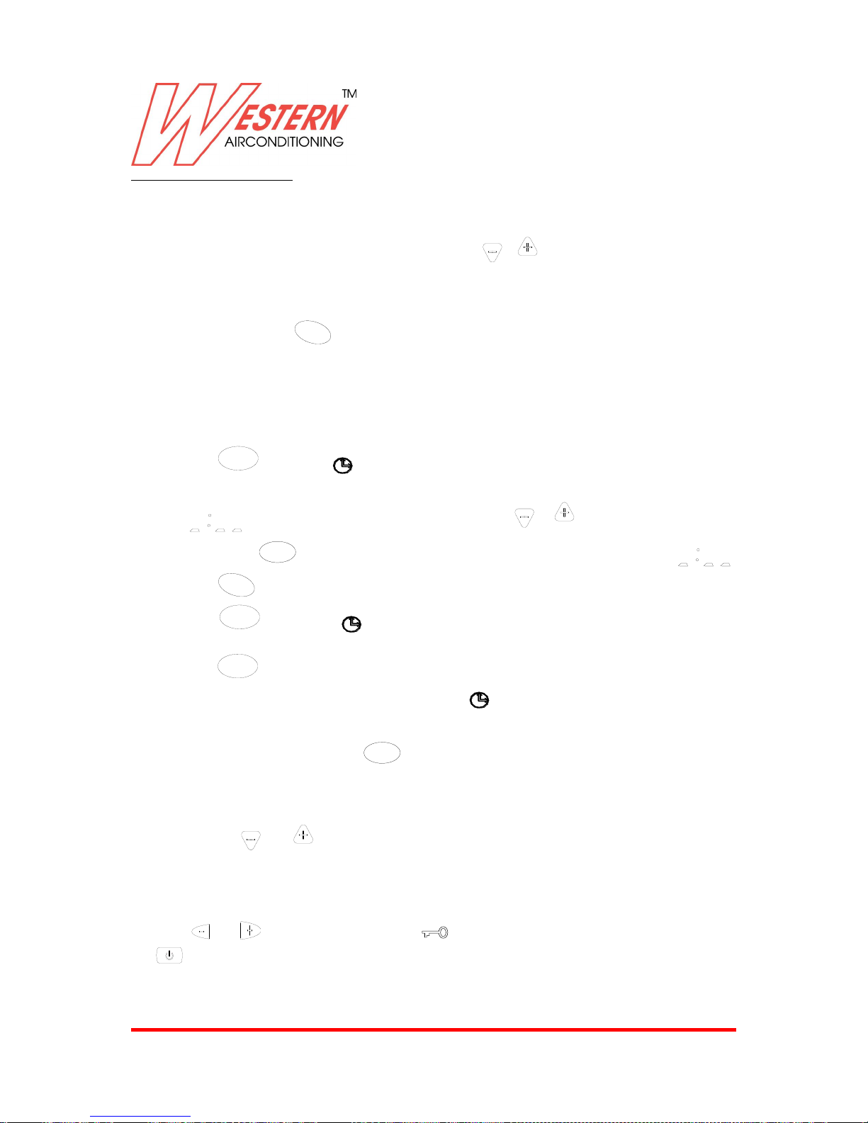
Exclusive Wall Pad Operation
1) Clock display and setting
System has an accurate internal real time clock used for time indication and timer ON/OFF function. Normally, time
clock display area indicates internal time clock which can be set by
TIME
or
TIME
button.
2) Day display and setting
The wall pad support day display function, it can be used as day indication and timer ON/OFF function, day display icon
indicates current day. Press
DAY
button to set day.
3) Timer ON/OFF setting
If master unit is in global control mode and on/off timer setting is reached, master unit will command the whole
network to be on or off. Otherwise timer on/off is effective to the local unit only. The system supports 7 days on/off
timer setting.
a) Press
TIMER
button once, and
ON
symbol blinking indicates on timer programming mode, day display
area indicates the day for setting on timer on. If on timer for this day is null, timer display area shows
, otherwise the on timer setting will be shown. Press
TIME
or
TIME
button to change the on timer
setting. Press
CANCEL
key to cancel the current on timer selected and the timer display area shows .
Press
DAY
button to change the day the on timer to be programmed.
b) Press
TIMER
button again, and
OFF
symbol blinking indicates off timer programming mode. The
setting method is the same as on timer setting above.
c) Press
TIMER
button again, to exit timer on/off setting function.
d) Should there be any on or off timer being programmed, will light up. Should there be any unexecuted on
or off timer for the current day, its corresponding ON or
OFF
icon will light up.
e) If the system is healthy, hold down
CANCEL
button for 3 sec will cancel all timer settings.
Clock synchronization by master unit is as follow:
1. Press
TIME
and
TIME
buttons for 3sec to activate clock synchronization to all salve units. Master wall pad
responses with a beeping sound.
4) Key lock
In order to prevent unauthorized access to the system setting, a key lock function is provided to prevent mischief. Hold
down and for 3 sec to activate key lock, symbol lights up. Repeat the same to exit key lock. Only
button is applicable in key lock mode.
Page 49
Western Airconditioning B.V. reserves the right to alter specifications
49
5) Sleep
Press
SLEEP
button to activate or deactivate sleep setting. Sleep is valid in cool or heat mode only.
6) Temperature setting
Press or to enter into temperature setting mode, temperature display area blinks the current set
temperature. Press the above button to adjust the set temperature.
7) Mode setting
Press
MODE
button to change the operation mode.
8) Fan speed setting
Press “
FAN
+-”button to change the fan speed, only low speed available for dehumidification mode.
9) On/Off control
Press to start or stop the air conditioner.
10) Networking control (only master unit wall pad can control other units on the network)
Press
NET
button to enter into networking control mode. Unit area blinking indicates the slave unit
under control. Press
TIME
or
TIME
to select the desired slave unit, unit that offline will be skipped
automatically. Parameters that can be controlled are on/off, set temperature, mode, fan speed, swing and
sleep, operation methods are the same as above. Press
NET
button again to exit networking control
mode.
press
GROUP
buttons to enter into global control mode, lights up. Repeat the same to exit global
control mode. In global control mode, the setting of master unit will broadcast to all the slave units.
11) Parameter browsing
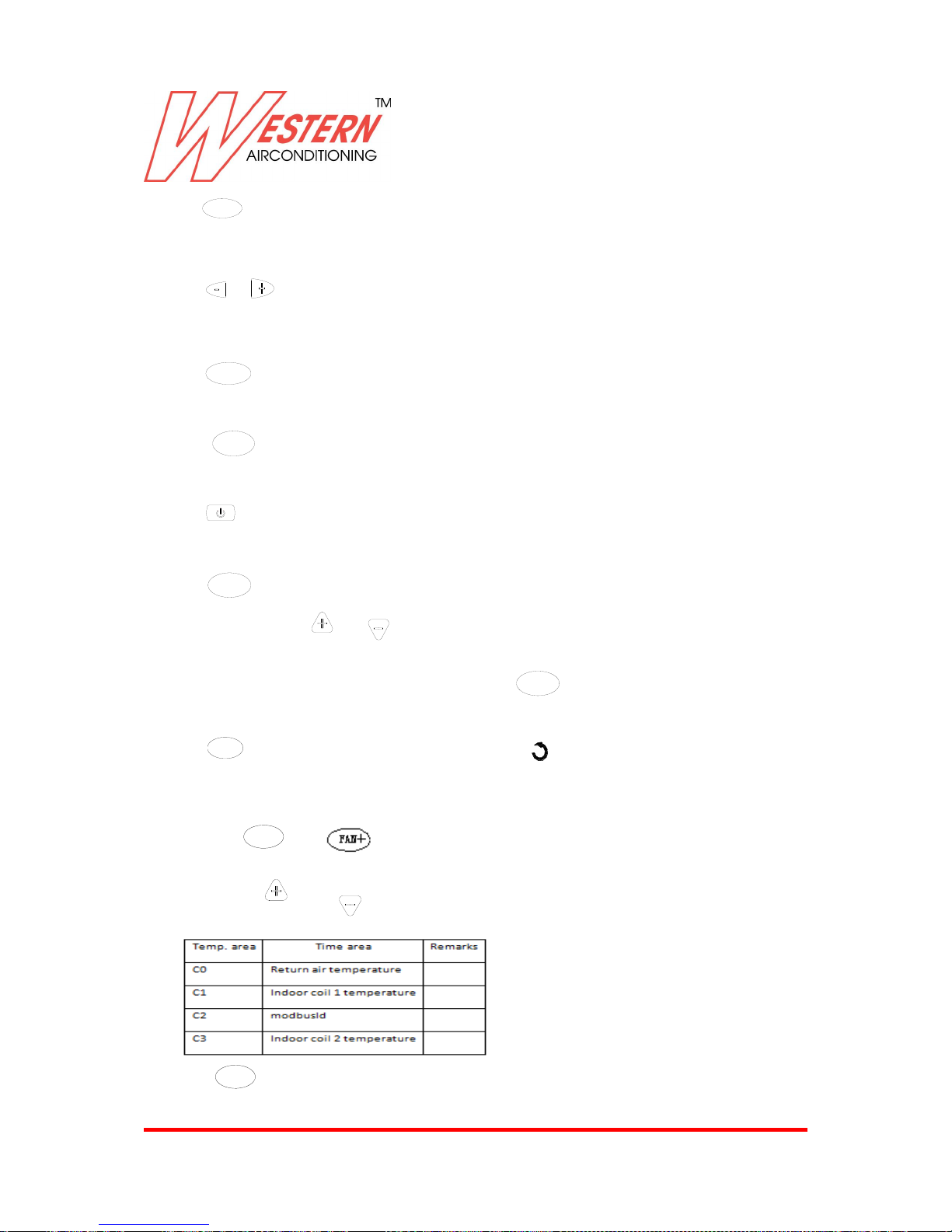
Hold down
CANCEL
and “ ”buttons for 3 sec to enter into parameters browsing mode. Unit display
area shows the slave unit under browsing. Slave unit selection method is the same as in networking control
above. Press
HUMIDIFY
or
HUMIDIFY
to browse various parameters as follow:-
Press
CANCEL
button to exit.
Page 50
Western Airconditioning B.V. reserves the right to alter specifications
50
12) Error indication
When faulty slave unit is detected, unit display area shows the faulty unit address, time area shows the
error code and backlight change to red color. Should there be multiple units having problems, they will be
shown one after another.
For system without master-slave wall pad will indicate unit error codes as above.
Short Time: long pressed “cancel+fan-“ key within 10 seconds powered will send short time command, and
then the main board will come in short time state. Every timer which long than 1 min will short 10 times;
Long pressed “GROUP+SLEEP” key will come in Fahrenheit/Celsius setting. The display of temperature will
trans in Fahrenheit and Celsius.
Page 51
Western Airconditioning B.V. reserves the right to alter specifications
51
CLEANING
Cleaning the air filter
Disconnect the power supply before cleaning and maintenance.
The filters should be regularly cleaned to keep the air conditioner running efficiently. Clean the
filters every two weeks.
EXTERNAL CLEANING AND EXTRA MAINTENANCE
--Disconnect the air conditioner from the electrical supply.
--Wipe external surfaces clean with a damp cloth only.
--Do not use an abrasive cloth and/or solvents as this may damage the surfaces.
--Do not use excessively wet cloth or sponge, as water stagnation could damage the air conditioner and
compromise safety
-- once in a year, evacuating air from both radiator and main coil of the unit as indicated at page 34
How to Proceed:
--Disconnect the air conditioner from the
electrical supply.
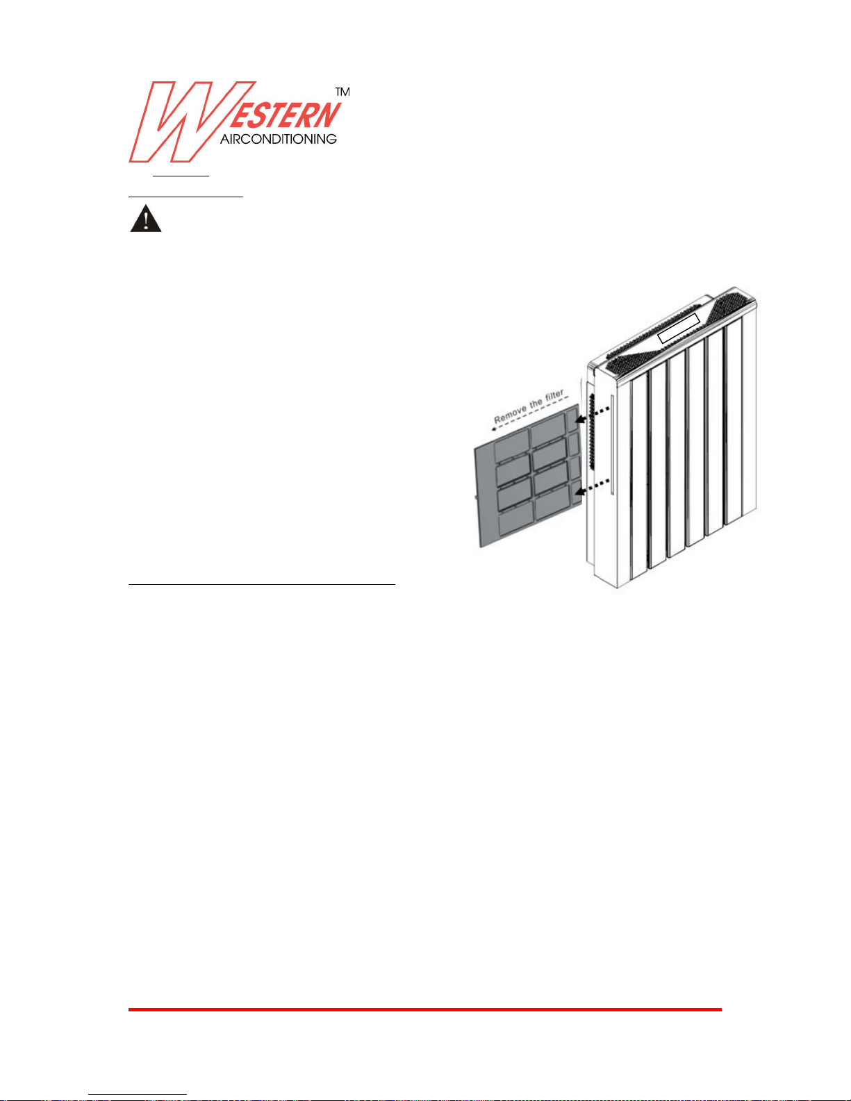
--The air filter is behind the radiator. Extract the
filter grating, both sides should be available,
just depend on the installation position.
--Proceed to wash and dry all the filters, and
replace them in the same way.
Attention:
Do not use the air conditioner without filters as
it could be seriously damage the air conditioner
Page 52
Western Airconditioning B.V. reserves the right to alter specifications
52
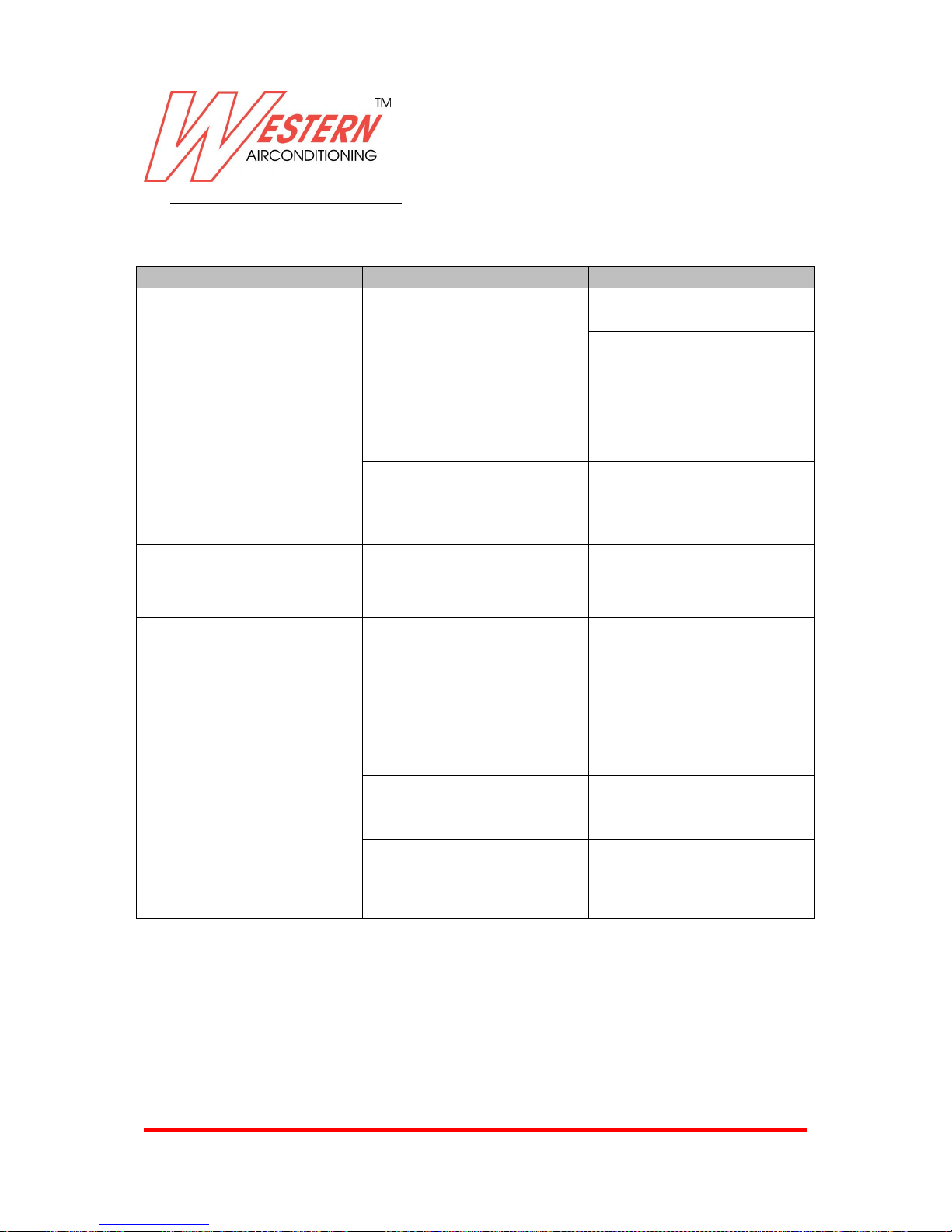
7. TABLE OF ANOMALIES AND REMEDIES
The assistance must be supplied by a qualified installer or by a specialized service center.
Effect
Cause
Remedy
The unit does not turn on
No power supply
Check that main power is
present(red LED is on)
Check if the master switch is
closed, or if a fuse is burnt
The appliance does not
active the ventilation
Not hot or cold water in the
system
Check the water boiler or
cooler are functioning
correctly
Static mode is activated
Check if static function is
activated on command on
board
The radiator does not reach a
uniform heating temperature
Air present in the inner
circuit of the appliance
Release the air several time
The ventilation speed
increase of decreases
automatically
The electronic control adjust
the comfort level regularly in
Auto mode
Select Cooling or heating
mode and desired fan speed
The unit does not cool or
heat adequately
The temperature set on the
thermostat is either too high
or too low
Check the temperature
setting on the thermostat
and correct it if needed
The air filter is blocked
Check and clean it if needed
Indoor air flow obstacles are
present
Remove anything that might
clog the air flow
Page 53
Western Airconditioning B.V. reserves the right to alter specifications
53
Alarm code definition(Exclusive)
When there is problem with the system, LCD on the top of unit would display the alarm code accordingly.
Description of Alarm
Alarm code
Return air sensor faulty
E1
Indoor coil sensor faulty
E2
PG1/PG2 motor faulty
E3/E4
Anti-cold air protection
E5
Anti-hot air protection
E6
Indoor coil low temperature protection
E7
Local communication error
E8
Mode error Water pump faulty
E9
Water pump faulty
Ea (command on board), E10(wired wall pad)
Indoor coil over heat protection
Eb(command on board), E11(wired wall pad)
Page 54
Western Airconditioning B.V. reserves the right to alter specifications
54
Doppio (Exclusive) - 07072015
Western Airconditioning B.V.
De Wel 10, 3871 MV HOEVELAKEN
Tel. +31 (0) 33 247 78 00
www.western.nl
 Loading...