

Western TransCube, TransCube 10TCG, TransCube 05TCG, TransCube 20TCG, TransCube 50TCG Operator's Manual
...Page 1
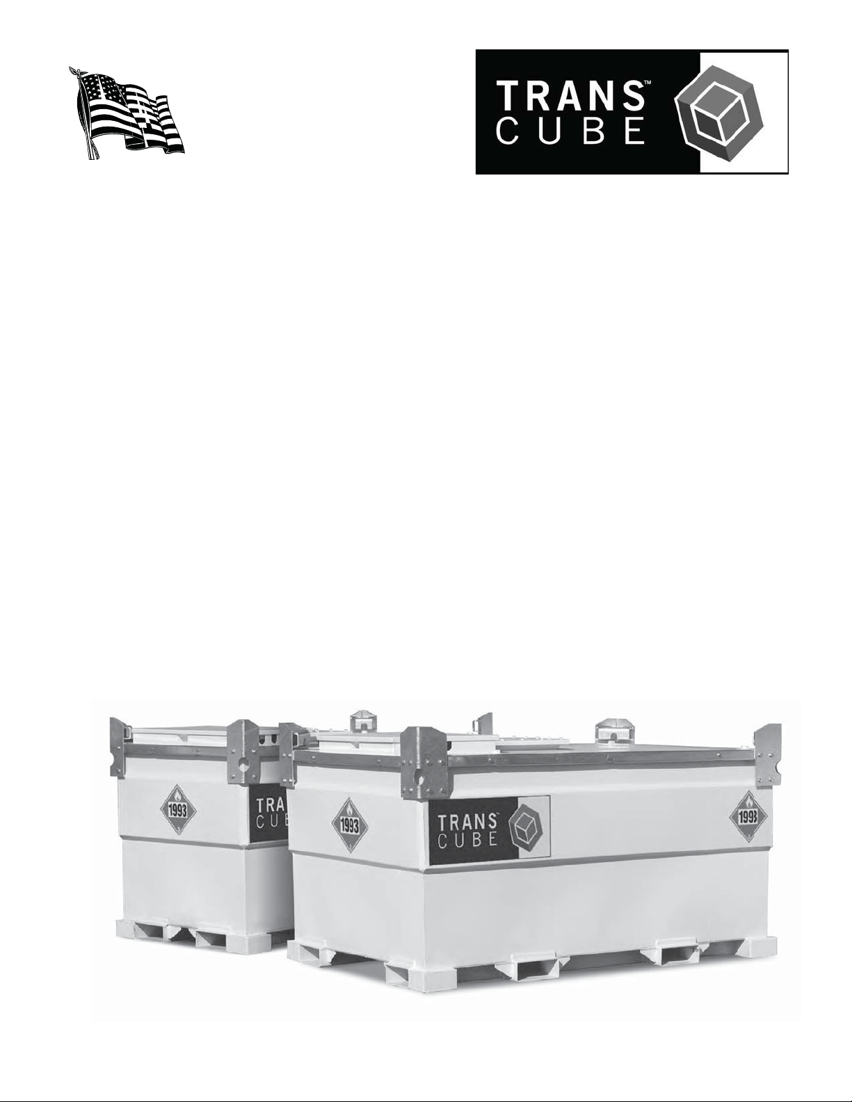
OPERATOR’S MANUAL
MODELS
05TCG
10TCG
20TCG
30TCG
50TCG
KEEP THESE INSTRUCTIONS WITH THE TRANSCUBE
Page 2

USER'S NOTICE
t Th e
t For use on sit e as a station t ank it is UL 142 listed f or just storage.
t
TransCube was designed for the transport of diesel fuel - UN 1202 / UN 1993.
t Regul ation size placar d s must b e on al l 4 sid es of t he TransCube o r it s means of t ran sport .
t The TransCube was manufactured t o t he Unit ed Nat ions speci fications (eg. 49 CFR Code of Produc-
tion) tested and cert ified as a UN St andard Mobil e IBC, 31 AY Packing Group III. This is an int ernational standard recognized by TDG whether made in USA or imported and DOT’s o ce 4 Hazarfous
Materials Safety (USA).
t Closures: In transport AL L valves and plugs must be closed. Ensure pump is turned o. The
closure system nearest the contents of the IBC must be closed fi rst. Close and lock the hatchlid.
t Fill t o a maximum of 95% capacit y.
t The TransCub e m ust be secu r ed fi rm ly t o i ts m eans o f tr an sp or t. Do no t dr i ll h ol es i n th e p ri mary o r
secondary tanks.
t Replacement of any comp onent must be t he same specifi cation or e quivalent . Replacement parts can
be obtained from Western , Toll free: 866-814-247 0, Phon e: 203-847-430 0 or Fax: 203-847-431 0.
t Com pul sor y I n spect ion s: The Tr an sp or t o f Dan g ero u s Goo d s reg u lat ion s requ ir e t he IBC t o b e in -
spect ed every 60 mont hs at a government registered facil i t y. The Record Card must be filled out at
each test, and kept with the TransCube. The month and year o f the inspection must be stamped in
the space provided on the met al specificat i on plate.
t Ref er t o Operat or's Manual f or more d et ails. The o p erat o r m u st read and u n d erstand Manual b ef ore
using the TransCube.
ii
I
t is a double wall Intermediate Bulk Container (IBC).
WESTERN GLOBAL
INC.
Page 3

THE TRANSCUBE MOBILE IBC (INTERMEDIATE BULK CONTAINER)
FOR THE TRANSPORT OF DIESEL FUEL ON CANADIAN ROADS.
The UN (United Nations) approved Mobile IBC complies with the following regulations: the UK car-
riage of dangerous goods by road requirements and the European agreement concerning the inter-
national carriage of dangerous goods by road (ADR), US DOT and Transport USA. Transport of
Dangerous Goods Regulations apply when transporting the IBC empty or full with flammable liquid
of Transport Packing Group III (diesel fuel).
Instructions for Use
1. Ensure that the IBC placard is fitted to all sides with the correct U.N. Number, "Flammable Liquid Class
3 - Hazardous Diamond" and the proper shipping name, i.e. U.N. 1202 for diesel fuel.
2. Ensure that the driver has adequate instruction and training in IBC contents.
3. Ensure driver has appropriate training licence on him or her if required.
4. Ensure documents and Record Cards are carried.
5. Always follow the local or federal road regulations when transporting.
6. Do not allow riders on trailer.
7. Ensure that the TransCube is in good condition and that the certification period has not expired (refer
to TransCube Maintenance/Record Card on the date stamped on the specification plate).
8. Ensure that all valves are switched off when not in use and being transported.
9. Take care not to spill fuel on the ground or in the tank at all times when filling TransCube or dispensing
fuel.
10. Use on a level site.
To Fill Tank
1. Open filler cap slowly to relieve pressure (and vent cap if fitted), and fill with nozzle only. Do not hard
connect.
2. Watch for level on gauge.
3. When full or adequate amount required (maximum 95% of capacity of tank), replace cap and tighten.
Note: Hand tighten fill cap and then tighten another 1/4 turn to minimize the chance of leakage.
Dispensing Fuel
1. Open outlet ball valve. Ensure dispensing nozzle is held while your pump is operating.
2. When finished, ensure nozzle and hose are replaced in pump cabinet, and ball valve, pump and nozzle
are switched off.
If generator, feed and return lines are required, fit your choice of quick couplers to the designated points
and pass hoses through the access slot on the sides of the cabinet so that it remains lockable. It is
important to use the correct filter to match your diesel engine.
Note
These instructions apply to diesel fuel which is a hazardous material Packing Group III. If the IBC is
to be used for anything other than diesel fuel, please check with the local authorities and check that
the liquid falls within the Packing Group II or III and that the TransCube is labelled with the appropriate
number on the UN placards. If the IBC is used for a flammable liquid, local fire regulations should be
checked including the carrying of correct fire extinguishers.
iii
Page 4

MANUFACTURER
LIMITED WARRANTY
This warranty is in substitution of every warranty as to quality fitness or description expressed or implied by
statute, common law or custom.
WESTERN products are fully guaranteed for a period of one year from the date of purchase against faulty
workmanship or material. Faulty products should be returned by the customer to the supplier. The supplier
will replace or repair any faulty item free of charge, providing there is no obvious signs of abuse or indication
that the equipment has not been used accordance with the Manual or instructions, and where maintenance
is required this has been duly carried out. The above warranty covers only components made by us. Any
components that are not of our manufacture are covered by the original manufacturer's guarantee.
Pump, hose and nozzle are subject to a three month warranty from date of supply.
WARRANTY DOES NOT COVER: wear and tear caused by normal use, damage caused by accident, abuse,
off road use, faulty installation, misapplication, improper maintenance, violations of product manuals, warn-
ings, misuse of operation instructions or Acts of God.
UNDER NO CIRCUMSTANCE can WESTERN be liable for any charges in respect of labour, indirect losses,
consequential damage, loss of profit, loss of product, inability from use of product for any purpose whatso-
ever and all such fees and litigation.
WESTERN cannot be held liable for any misinterpretation of information given in this book. Further infor-
mation as to the transport of diesel on USA roads should be obtained by a Transport or Dangerous Goods
Advisor.
WARRANTY VOID IF NOT REGISTERED
WITHIN 30 DAYS OF PURCHASE DATE.
iv
Page 5
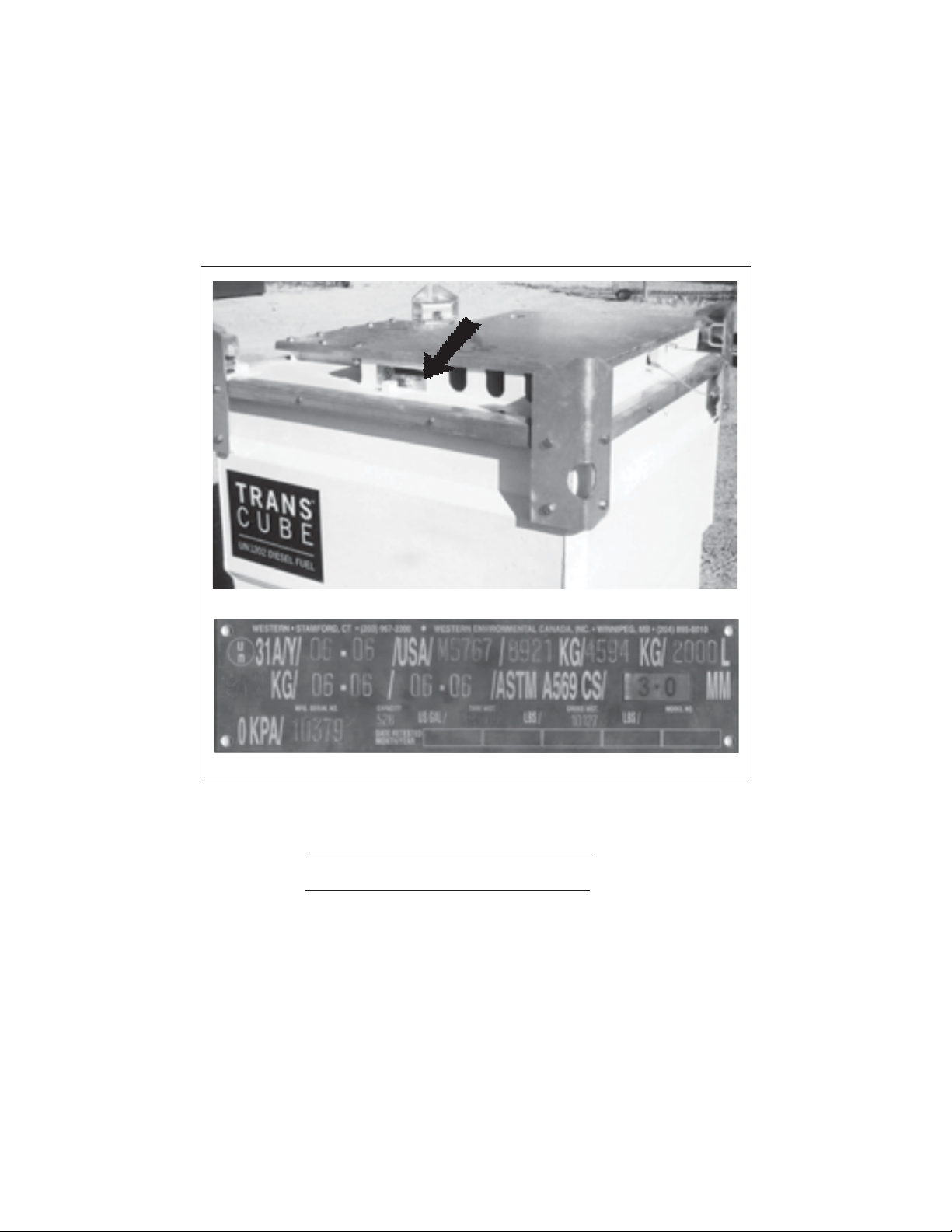
SERIAL NUM ER LOCATION
Always give your dealer the serial number of your Western Environmental TransCube when ordering
parts or requesting service or other information.
The serial number plate is located where indicated. lease mark the number in the space provided for
easy reference.
Model Number
Serial Number
Location
Serial Plate
v
Page 6

Page 7

TA LE OF CONTENTS
SECTION DESCRIPTION
Introduction ........................................................
Safety....................................................................
. General Safety.......................................................
. Equipment Safety Guidelines ................................
. Safety Training.......................................................
. Safety Signs ..........................................................
. reparation ............................................................
. Operating Safety....................................................
. Storage Safety.......................................................
. Transport Safety ....................................................
. Maintenance Safety...............................................
. Sign-Off Form ........................................................
3 Safety Si n Locations .........................................
Operation............................................................ 0
. To the New Operator or Owner............................
. Machine Components...........................................
. Machine reak-In ................................................
. re-Operation Checklist ......................................
. Controls ...............................................................
. Field Use .............................................................
. Cleaning ..............................................................
Record Form ......................................................
Trouble Shootin ............................................... 3
Specifications .................................................... 3
. Mechanical ..........................................................
. olt Torque...........................................................
. ydraulic Fitting Torque.......................................
Inde ................................................................... 3
vi
Page 8

Page 9
INTRODUCTION
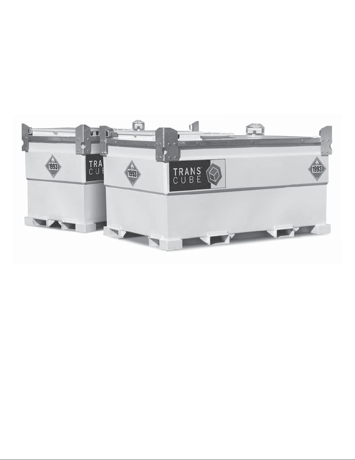
Congratulations on your choice of a TransCube to complement your refueling or transporting operation.
This equi pment has been designed and manufactured t o meet t he need s of a discriminat ing buyer for ef -
cien t refueling of equipment or t ransport ing of fuel.
Safe, ef cient and trouble free op erat i on of your TransCub e requires that you and anyone el se who will
be using or maintaining the tank, read and understand the Safety, Operation, Maintenance and Trouble
Shooting information contained within the Operator's Manual.
Thi s man ual cov e r s t h e Tran sCub e Mo d el s TCG, TCG, TCG, TCG and TCG. Use t he Tab l e
of Contents or Index as a guide to locate required information.
eep this manual handy for frequent reference and to pass on t o new operators or owners. Call your
dealer o r t he f act ory i f you need assist an ce, i n f o r m at io n o r ad d i ti onal cop i es of t h e manuals.
A document shelf is installed on the inside of the lid on most models for keeping the manual and records
with the TransCube.
OPERATOR ORIENTATION - The directions left, right, front and rear, as mentioned throughout this
manual, are as seen from the op en cover and l ooking t oward t he unit.
Page 10

SAFETY
SAFETY ALERT SYM OL
This Safety Alert symbol means
ATTENTION ECOME ALERT
YOUR SAFETY IS INVOLVED
Why is SAFETY important to you
3 i Reasons
SIGNAL WORDS
Note the use of the signal words DANGER,
WARNING and CAUTION with the safety
messages. The appropriate signal word for
each message has been selected using the
following guide-lines:
The Safety Alert symbol identi-
fies important safety messages on
the TransCube and in the manual.
When you see this symbol, be alert
to the possibility of personal in ury or
death. Follow the instructions in the
safety message.
Accidents Disable and ill
Accidents Cost
Accidents Can e Avoided
DANGER - Indicates an imminently ha ardous
situation that, if not avoided, will
result in death or serious in ury. This
signal word is to be limited to the
most extreme situations typically for
machine components which, for func-
tional purposes, cannot be guarded.
WARNING - Indicates a potentially ha ardous
situation that, if not avoided, could
result in death or serious in ury, and
includes ha ards that are exposed
when guards are removed. It may
also be used to alert against unsafe
practices.
CAUTION - Indicates a potentially ha ardous
situation that, if not avoided, may
result in minor or moderate in ury. It
may also be used to alert against
unsafe practices.
If you have any questions not answered in this manual or require additional copies or the manual is damaged, please contact your dealer or Western, ois Street, Norwalk CT, , hone: - ,
Fax: - , Toll Free: - - - .
Page 11

SAFETY
2.1 GENERAL SAFETY
YOU are responsible for the SAFE operation
and maintenance of your TransCube. YOU must
ensure that you and anyone else who is going to
use, maintain or work around the TransCube be
familiar with the using and maintenance proce-
dures and related SAFETY information contained
in this manual. This manual will take you step-bystep through your working day and alerts you to
all good safety practices that should be used while
using the TransCube.
Remember, YOU are the key to safety. Good
safety practices not only protect you but also the
people around you. Make these practices a working part of your safety program. Be certain that
EVERYONE using this equipment is familiar with
the recommended using and maintenance proce-
dures and follows all the safety precautions. Most
accidents can be prevented. Do not risk injury or
death by ignoring good safety practices.
• TransCube owners must give instructions to
operators or employees before allowing them
to use the tank, and at least annually thereafter per OSHA (Occupational Safety and
Health Administration) regulation 1928.57.
• The most important safety device on this
equipment is a SAFE operator. It is the operator’s responsibility to read and understand ALL
Safety and Using instructions in the manual
and to follow these. Most accidents can be
avoided.
1. Read and understand the Operator’s Manual and all safety
signs before using, maintaining, adjusting or cleaning the
TransCube.
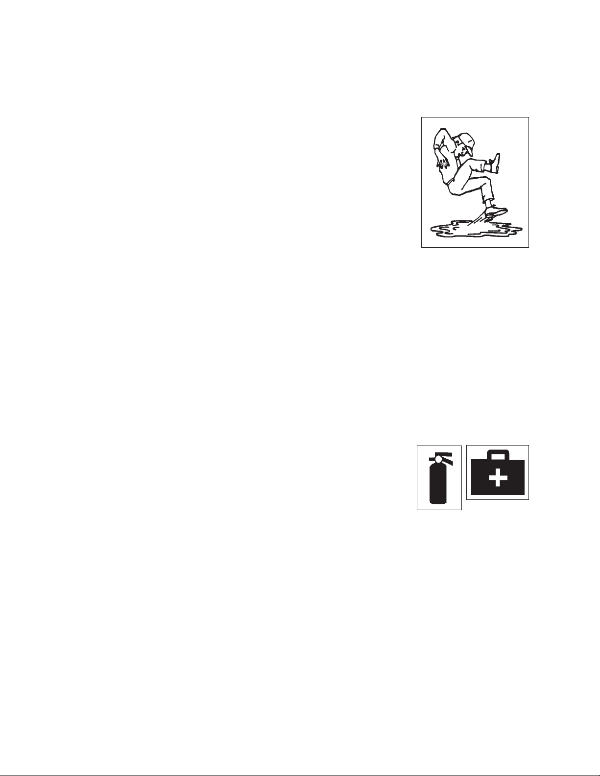
2. Have a first-aid kit available
for use should the need
arise and know how to use
it.
3. Have a fire extinguisher
available for use should the
need arise and know how to
use it.
4. Wear appropriate
protective gear.
This list includes but
is not limited to:
- A hard hat
- Protective shoes
with slip resistant soles
- Protective glasses, goggles or face shield
- Heavy gloves
- Protective clothing
5. Install and secure all guards before starting.
• A person who has not read and understood
all using and safety instructions is not quali-
fied to use the machine. An untrained operator
exposes himself and bystanders to possible
serious injury or death.
• Do not modify the equipment in any way.
Unauthorized modification may impair the
function and/or safety and could affect the life
of the equipment.
• Think SAFETY! Work SAFELY!
6. Do not allow riders.
7. Do not smoke when refueling.
Keep sparks, flames and hot
material away from fuel and
TransCube.
8. Place all controls in neutral, disconnect power
source to pump and wait for all moving parts
to stop before servicing, adjusting, repairing or
cleaning.
9. Clear the area of people, especially small
children, before using the unit.
10. Review safety related items annually with all
personnel who will using or maintaining the
TransCube.
3
Page 12

2.2 EQUIPMENT SAFETY GUIDELINES
1. Safety of the operator and bystanders is one
of the main concerns in designing and de-
veloping a machine. However, every year
many accidents occur which could have been
avoided by a few seconds of thought and a
more careful approach to handling equipment.
You, the operator, can avoid many accidents
by observing the following precautions in this
section. To avoid personal injury or death,
study the following precautions and insist
those working with you, or for you, follow
them.
2. In order to provide a better view, certain
photographs or illustrations in this manual
may show an assembly with a safety shield
removed. However, equipment should never
be used in this condition. Keep all shields in
place. If shield removal becomes necessary
for repairs, replace the shield prior to use.
3. Replace any safety sign or instruction sign
that is not readable or is missing. Location of
such safety signs is indicated in this manual.
4. Never use alcoholic beverages or drugs which
can hinder alertness or coordination while us-
ing this equipment. Consult your doctor about
using this machine while taking prescription
medications.
5. Under no circumstances should young
children be allowed to work with this
equipment. Do not allow persons to use or
assemble this unit until they have read this
manual and have developed a thorough
understanding of the safety precautions
and of how it works. Review the safety
instructions with all users annually.
7. Keep all flames, sparks or smoking material
away from TransCube and working area. Do
not smoke around unit.
8. Never exceed the limits of a piece of machinery. If its ability to do a job, or to do so safely,
is in question - DON'T TRY IT.
9. Do not modify the equipment in any way. Un-
authorized modification may result in serious
injury or death and may impair the function
and life of the equipment.
10. In addition to the design and configuration of
this implement, including Safety Signs and
Safety Equipment, hazard control and accident prevention are dependent upon the
awareness, concern, prudence, and proper
training of personnel involved in the operation,
transport, maintenance, and storage of the
machine. Refer also to Safety Messages and
operation instruction in each of the appropriate sections of the machine Manuals. Pay
close attention to the Safety Signs affixed to
the equipment.
11. It is a serious offence to contaminate the
ground or any water supply with spilt fuel.
Care must be taken when filling TransCube
or refueling equipment from the TransCube.
Stay and monitor fuel transfers to prevent
overfilling or spilling fuel on the ground or in
the interstice.
6. This equipment is dangerous to children and
persons unfamiliar with its operation. The
operator should be a responsible, properly
trained and physically able person familiar
with refueling machinery and trained in this
equipment's operations. If the elderly are
assisting with work, their physical limitations
need to be recognized and accommodated.
4
Page 13

2.3 SAFETY TRAINING
2.4 SAFETY SIGNS
1. Safety is a primary concern in the design and
manufacture of our products. Unfortunately,
our efforts to provide safe equipment can
be wiped out by a single careless act of an
operator or bystander.
2. In addition to the design and configuration of
equipment, hazard control and accident pre-
vention are dependent upon the awareness,
concern, prudence and proper training of
personnel involved in the operation, transport,
maintenance and storage of this equipment.
3. It has been said, "The
best safety feature is an
informed, careful operator." We ask you to be that
kind of an operator. It is the
operator's responsibility to read and understand ALL Safety and Using instructions in the
manual and to follow these. Accidents can be
avoided.
4. Working with unfamiliar equipment can lead
to careless injuries. Read this manual before
assembly or using, to acquaint yourself with
the machine. If this machine is used by any
person other than yourself, or is loaned or
rented, it is the machine owner's responsibility to make certain that the operator, prior to
using:
1. Keep safety signs clean and legible at all
times.
2. Replace safety signs that are missing or have
become illegible.
3. Replaced parts that displayed a safety sign
should also display the current sign.
4. Safety signs displayed in Section 3 each have
a part number in the lower right hand corner.
Use this part number when ordering replace-
ment parts.
5. Safety signs are available from your authorized Distributor or Dealer Parts Department or
the factory.
How to Install Safety Signs:
• Be sure that the installation area is clean and
dry.
• Be sure temperature is above 50°F (10°C).
• Determine exact position before you remove
the backing paper. (See Section 3).
• Remove the smallest portion of the split backing paper.
a. Reads and understands the operator's
manuals.
b. Is instructed in safe and proper use.
5. Know your controls and how to stop unit
quickly in an emergency. Read this manual
and the one provided with your equipment.
6. Train all new personnel and review instructions frequently with existing workers. Be
certain only a properly trained and physically
able person will use the machinery. A person
who has not read and understood all using
and safety instructions is not qualified to use
the machine. An untrained operator exposes
himself and bystanders to possible serious in-
jury or death. If the elderly are assisting with
the work, their physical limitations need to be
recognized and accommodated.
• Align the sign over the specified area and
carefully press the small portion with the ex-
posed sticky backing in place.
• Slowly peel back the remaining paper and
carefully smooth the remaining portion of the
sign in place.
• Small air pockets can be pierced with a pin
and smoothed out using the piece of sign
backing paper.
5
Page 14
2.5 PREPARATION
2.6 OPERATING SAFETY
1. Never use the unit until you have read and
completely understand this manual and each
of the Safety Messages found on the safety
signs on the unit.
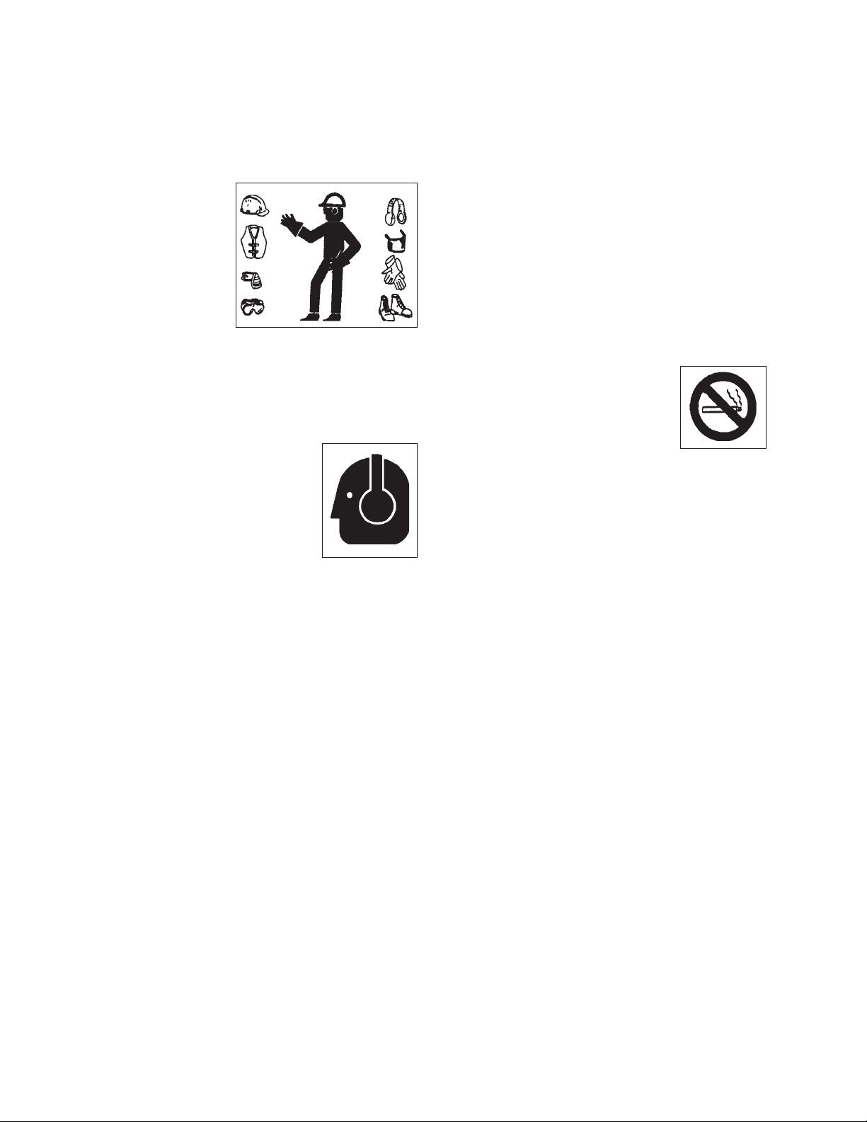
2. Personal protection equipment including hard hat,
safety glasses,
safety shoes,
and gloves are
recommended
during assembly, installation,
operation, adjustment, maintaining, repairing,
removal, cleaning, or moving the unit. Do not
allow long hair, loose fitting clothing or jewelry
to be around equipment.
3. PROLONGED EXPOSURE
TO LOUD NOISE MAY
CAUSE PERMANENT
HEARING LOSS!
Power equipment with or
without equipment attached
can often be noisy enough
to cause permanent, partial
hearing loss. We recommend that you wear
hearing protection on a full-time basis if the
noise in the Operator's position exceeds 80db.
Noise over 85db on a long-term basis can
cause severe hearing loss. Noise over 90db
adjacent to the Operator over a long-term basis may cause permanent, total hearing loss.
NOTE: Hearing loss from loud noise (from
tractors, chain saws, radios, and other such
sources close to the ear) is cumulative over a
lifetime without hope of natural recovery.
1. Please remember it is important that you read
and heed the safety signs on the TransCube.
Clean or replace all safety signs if they cannot be clearly read and understood. They are
there for your safety, as well as the safety of
others. The safe use of this tank is strictly up
to you, the operator.
2. Use only for the transport of diesel fuel for
refueling equipment or stand-by generators.
3. Keep the tank level when filling.
4. Fill only with a hand-held trigger nozzle. Take
care not to spill any fuel on the ground or in
the interstice.
5. Do not smoke when refueling.
Keep sparks, flames and hot
material away from fuel and
TransCube.
6. Do not over fill. 95% is the maximum legal
limit.
7. Always replace filler cap and turn pump off
(lever down) when refueling finished.
8. Store diesel hose and nozzle inside outer
tank.
9. Close all valve outlets and lock lid when transporting on public highway.
10. Follow the regulations for transport of Danger-
ous Goods.
11. Check for fluid in outer tank and empty
regularly - refer to maintenance manual for
detailed procedure.
4. Use only in daylight or good artificial light.
5. Be sure machine is properly mounted, adjusted and in good using condition.
6. Ensure that all safety shielding and safety
signs are properly installed and in good condition.
6
2.7 STORAGE SAFETY
1. Store the unit in an area away from human
activity.
2. Do not permit children to play on or around
the stored machine.
3. Store the unit in a dry, level area. Support the
frame with planks if required.
4. Disconnect all power connections and close
all valves before storing.
Page 15
2.8 TRANSPORT SAFETY
2.9 MAINTENANCE SAFETY
1. Read and follow the Operator's Manual before
using the TransCube.
2. Review and follow the User's Notice inside the
lid before using.
3. Be familiar with the requirements of "Trans-
port of Dangerous Goods" regulations and
follow them.
4. Train all drivers about the requirements of
transporting an Intermediate Bulk Container
(IBC). Do not allow untrained personnel to
drive.
5. Be sure each driver has the appropriate drivers licence required by the Federal, Provincial/State or local authorities.
6. Keep shipping papers describing tank and
contents with vehicle at all times.
7. Keep current Test Record Card with tank at all
times.
8. Keep Transport of Dangerous Goods (TDG)
Regulation Placard with the appropriate UN
number on each of the vertical sides when
transporting. Cover placards when tank is
empty and purged.
9. Securely anchor tank to truck with bolts before
transporting.
10. Turn off pump (move lever down) and close
generator port valves.
11. Be sure filler cap is on and closed securely.
12. Be sure all outlets are securely closed/
plugged with plugs provided by the manufacturer.
13. Ensure outer tank is empty of spillage.
14. Close and padlock hatch to prevent vibration
releasing the catch.
1. Good maintenance is your responsibility.
Poor maintenance is an invitation to trouble.
2. Follow good shop practices.
- Keep service
area clean and
dry.
- Be sure electri-
cal outlets and
tools are properly grounded.
- Use adequate
light for the job
at hand.
3. Make sure there is plenty of ventilation.
Never use the engine of the transport vehicle
in a closed building. The exhaust fumes may
cause asphyxiation.
4. Before working on this machine. Disconnect
the power to the pump and close all valves.
5. Do not smoke when performing any maintenance work. Keep sparks, open flames and
hot material away from work site.
6. Always use personal protection devices such
as eye, hand and hearing protectors, when
performing any service or maintenance.
7. A fire extinguisher
and first aid kit
should be kept
readily accessible
while performing
maintenance on
this equipment.
8. Periodically tighten all bolts, nuts and screws
and check that all electrical connections are
properly secured to ensure unit is in a safe
condition.
9. When completing a maintenance or service
function, make sure all safety shields and
devices are installed before placing unit in
service.
10. Establish a lock-out tag-out policy for the work
site. Be sure all personnel are trained in and
follow all procedures.
7
Page 16

2.10 SIGN-OFF FORM
The equipment provider follows the general Safety Standards specified by the UN/DOT for the transport
of diesel fuel. Anyone who will be using and/or maintaining the tank must read and clearly understand ALL
Safety, Usage and Maintenance information presented in this manual.
Do not use or allow anyone else to use this tank until such information has been reviewed. Annually review
this information before the season start-up.
Make these periodic reviews of SAFETY and OPERATION a standard practice for all of your equipment. We
feel that an untrained operator is unqualified to use this machine.
A sign-off sheet is provided for your record keeping to show that all personnel who will be working with the
equipment have read and understand the information in the Operator’s Manual and have been instructed in
the operation of the equipment.
SIGN-OFF FORM
DATE
EMPLOYEES SIGNATURE EMPLOYERS SIGNATURE
8
Page 17
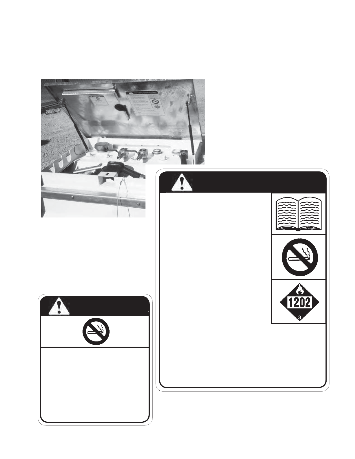
3 SAFETY SIGN LOCATIONS
The types of safety signs and locations on the equipment are shown in the illustrations that follow. Good
safety requires that you familiarize yourself with the various safety signs, the type of warning and the
area, or particular function related to that area, that requires your SAFETY AWARENESS.
• Think SAFETY! Work SAFELY!
B
A
A
OPERATING INSTRUCTIONS
• Read "Users Notice" and Operator's
Manual before using fuel tank.
• This equipment is designed for the transport of diesel fuel, for refueling equipment
or generator stand-by.
•
The tank must be level while filling.
• Fill only with a hand held trigger nozzle.
Take care not to spill on the ground or in
the tank.
B
DANGER
FIRE HAZARD
NO SMOKING
To prevent serious injury or death
from fire:
• Do not smoke when refueling.
• Keep sparks, flames and hot material away from fuel and TransCube.
TC0207
•
Do not smoke when refueling. Keep
sparks, flames and hot material away
from fuel and fuel tank.
•
Do not overfill. 95% capacity is maximum
legal limit.
• Always replace filler cap and turn pump
off (lever down).
• Store diesel hose and nozzle inside outer tank.
• Close all valve outlets and lock lid when transporting on public
highway.
• Follow the regulations for Transport of Dangerous Goods.
• Check for fluid in outer tank and empty regularly - refer to mainte-
nance manual for detailed procedure.
REMEMBER - If safety signs have been damaged, removed,
become illegible or parts replaced without safety signs, new signs
must be applied. New safety signs are available from your author-
ized dealer.
TC0206
9
Page 18

4 OPERATION
OPERATING SAFETY
• Please remember it is important that you
read and heed the safety signs on the TransCube. Clean or replace all safety signs if
they cannot be clearly read and understood.
They are there for your safety, as well as the
safety of others. The safe use of this tank is
strictly up to you, the operator.
• Use only for the transport of diesel fuel for
refueling equipment or stand-by generators.
• Keep the tank level when filling.
• Fill only with a hand-held trigger nozzle.
• Do not spill fuel on the ground or in the tank.
• Do not smoke when refueling. Keep sparks,
flames and hot material away from fuel and
TransCube.
• Do not over fill. 95% is the maximum legal
limit.
• Always replace filler cap and turn pump off
(lever down) when refueling finished.
• Store diesel hose and nozzle inside outer
tank.
• Close all valve outlets and lock lid when
transporting on public highway.
• Follow the regulations of theTransport of
Dangerous Goods.
• Check for fluid in outer tank and empty
regularly - refer to maintenance manual for
detailed procedure.
4.1 TO THE NEW OPERATOR OR OWNER
The TransCube is a double-walled steel tank with
baffles and an electric pump for transferring diesel
fuel. It was tested and certified to UN require-
ments and is legal to use in Canada and the U.S.
Be familiar with the machine before starting.
It is the responsibility of the owner or operator to read this manual and to train all other
operators before they start working with the
machine. Follow all safety instructions exactly. Safety is everyone's business. By following recommended procedures, a safe working
environment is provided for the operator,
bystanders and the area around the worksite.
Untrained operators are not qualified to use
the machine.
In addition to the design and configuration of
equipment, hazard control and accident prevention are dependent upon the awareness,
concern, prudence and proper training of
personnel involved in the operation, transport,
maintenance and storage of equipment. It is
the responsibility of the owner or operator to
read this manual and to train all other operators before they start working with the machine.
Many features incorporated into this machine are
the result of suggestions made by customers like
you. Read this manual carefully to learn how to
use the tank safely and how to set it to provide
maximum field efficiency. By following the using
instructions in conjunction with a good maintenance program, your TransCube will provide many
years of trouble-free service.
10
Page 19
. MACHINE
COMPONENTS
D
H
O
E
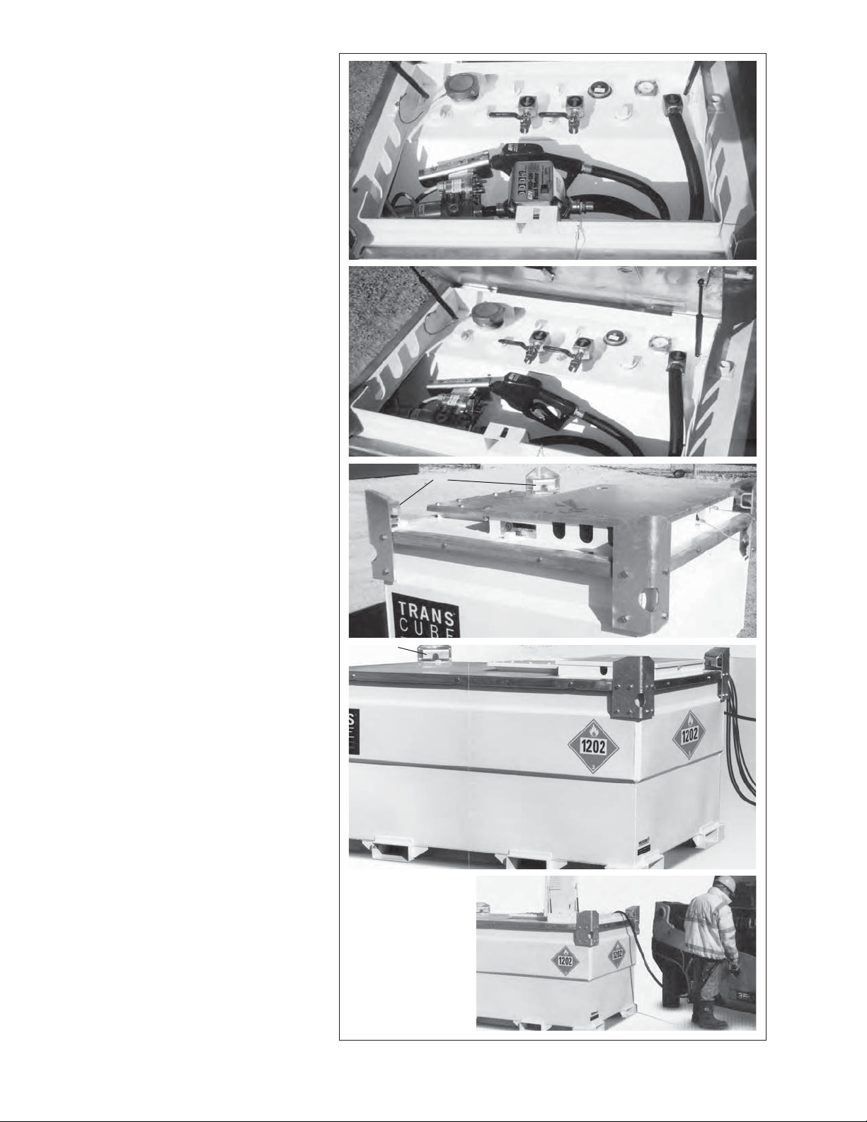
The TransCube i s a doub l e-w alled
tank for holding, transferring or
transport i ng fuel. The fuel t ank
mounts inside the outer tank. The
TransCub e is d esi gn ed so t he ou t er
tank is large enough to hold all
the uid shoul d t he in ner fuel t ank
break, crack or leak capacit y
in the interstice .
Close and lock the lid when trans porting or not using the tank. The
inch ll plug is located on the inner
tank along with the psi fusible plug
for venting. A fuel gauge is mounted
next to the ll plug to assist in lling
the tank.
An el ect ric p ump, hose and h andhel d no le are used t o transfer fuel
and the no le hooks to the side
frame. ower must be supplied by
the customer to power the pump.
Output and return line with valves
can be connected to an engine
operat ing at a remot e lo cat i on.
The outer tank is designed with an
access hole for routing fuel lines if
required for your application.
An optional volume meter can be
mounted under the lid to measure
the amount of fuel b eing dispensed.
TDG placar d s are l o cat ed on each
side of the tank.
W
W
W
R
F
W
L
M
P
G
C
D
L
M
FR
G
H
O
E
X
NT
W
W
S
A
X
N
W
C
T
S
C
T
S
A Outer Tan
with removable lid
Inner Tan
C Hatch Lid
D Filler Cap 3
E Fuel Gau e
F Electric Pump
G Pump ON OF
H Fuel Feed Line Valve
Fuel Ret urn Line Valve
Re f u e l i n Ho se
L Nozzle
M Nozzle Stora e rac et
N Manhole Cover
O Relief Vent
P Optional Fuel Meter
TDG Placards
R Power Cord
S Tie down point
T Stac in rac ets
W Fuel Line Access Slot s
Lif t in brac e t
A
C
N
Fi . PRINCI PLE COM PONENTS
Page 20

4.3 MACHINE BREAK-IN
4.4 PRE-OPERATION CHECKLIST
Although there are no operational restrictions on
the TransCube when used for the first time, it is
recommended that the following mechanical items
be checked:
A. After Using for 1 and 5 Hours:
1. Check all nuts, bolts and other fasteners.
Tighten to their specified torque level.
2. Check that the fuel lines and connections
are in good condition and there are no
leaks.
3. Check that the electrical system is in good
condition. Be sure all terminals and connectors are clean and fully engaged.
4. Then go to the regular service schedule
as defined in Section 5.
Efficient and safe operation of the TransCube re-
quires that each operator reads and understands
the using procedures and all related safety precautions outlined in this section. A pre-operation
checklist is provided for the operator. It is important for both the personal safety and maintaining
the good mechanical condition of the TransCube
that this checklist is followed.
Before using the TransCube and each time there-
after, the following areas should be checked off:
1. Check that the TransCube is bolted or anchored to the transporting vehicle.
2. Disconnect and secure all the lines and hoses
before transporting.
3. Close and tighten filler cap when tank is full.
4. Turn pump off and disconnect or remove
power lines.
5. Check the interstice area (bund). Clean if
there is any debris, trash or diesel fuel.
6. Check that all the required documentation and
placards are with the unit and in good condition.
12
Page 21
4.5 CONTROLS
The TransCube is designed and built
with components that allow for easy
and convenient transporting, filling
and transferring fuel. Each operator
should be trained in TransCube operation before using and the controls on
the unit. They must also be required
to know all the legal and regulatory
regulations relating to the transporting
and handling of fuel.
Review the controls on the unit prior
to using and as a part of the regular
training program:
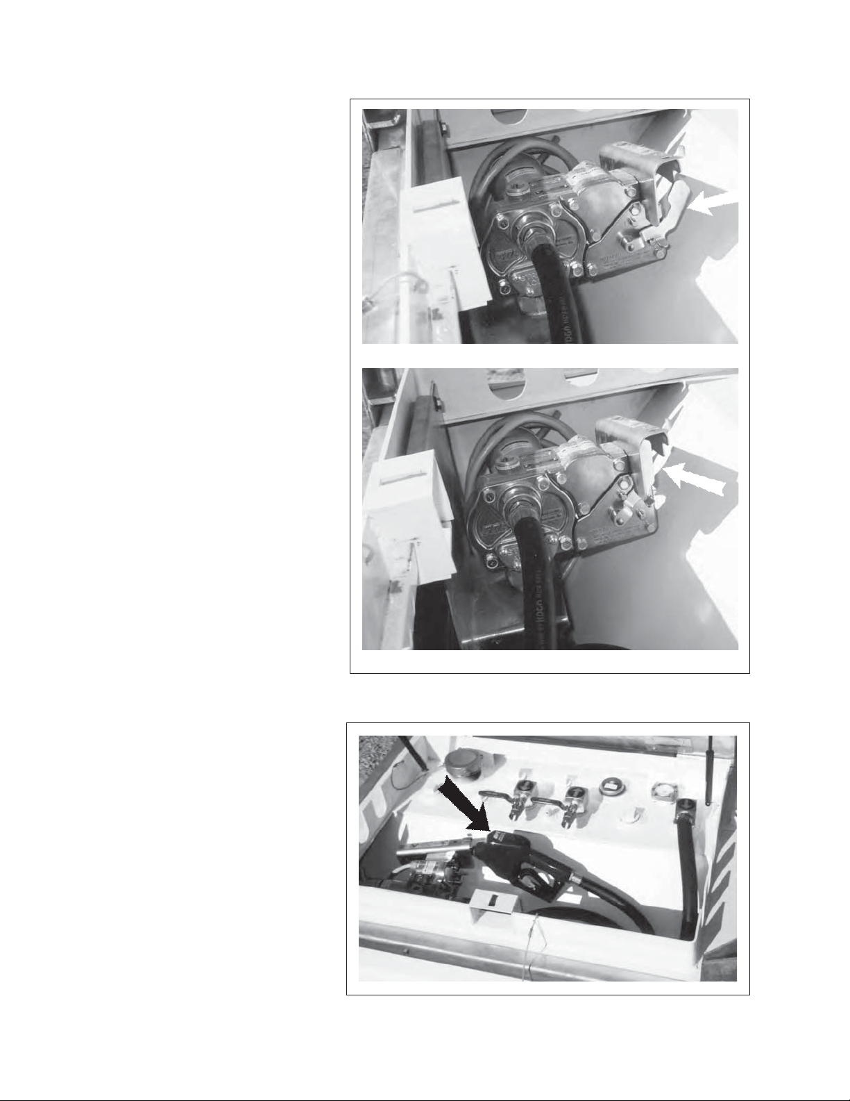
1. Pump ON/OFF:
This lever controls the power to
the transfer pump on the top of the
tank. Move the lever up to turn
the pump ON and down to turn
OFF.
2. Nozzle:
NOTE
The power cord must be connected or attached to a power source
for the pump to run.
NOTE
Depress the trigger on the hand-
held nozzle when transferring
fuel.
This hand-held nozzle is used to
transfer fuel. Depress the trigger on the nozzle to transfer fuel.
The pump must be connected
to a power supply and turned on
before transferring fuel.
Pump OFF
Pump ON
Fig. 2 UNDER LID
Fig. 3 NOZZLE
13
Page 22
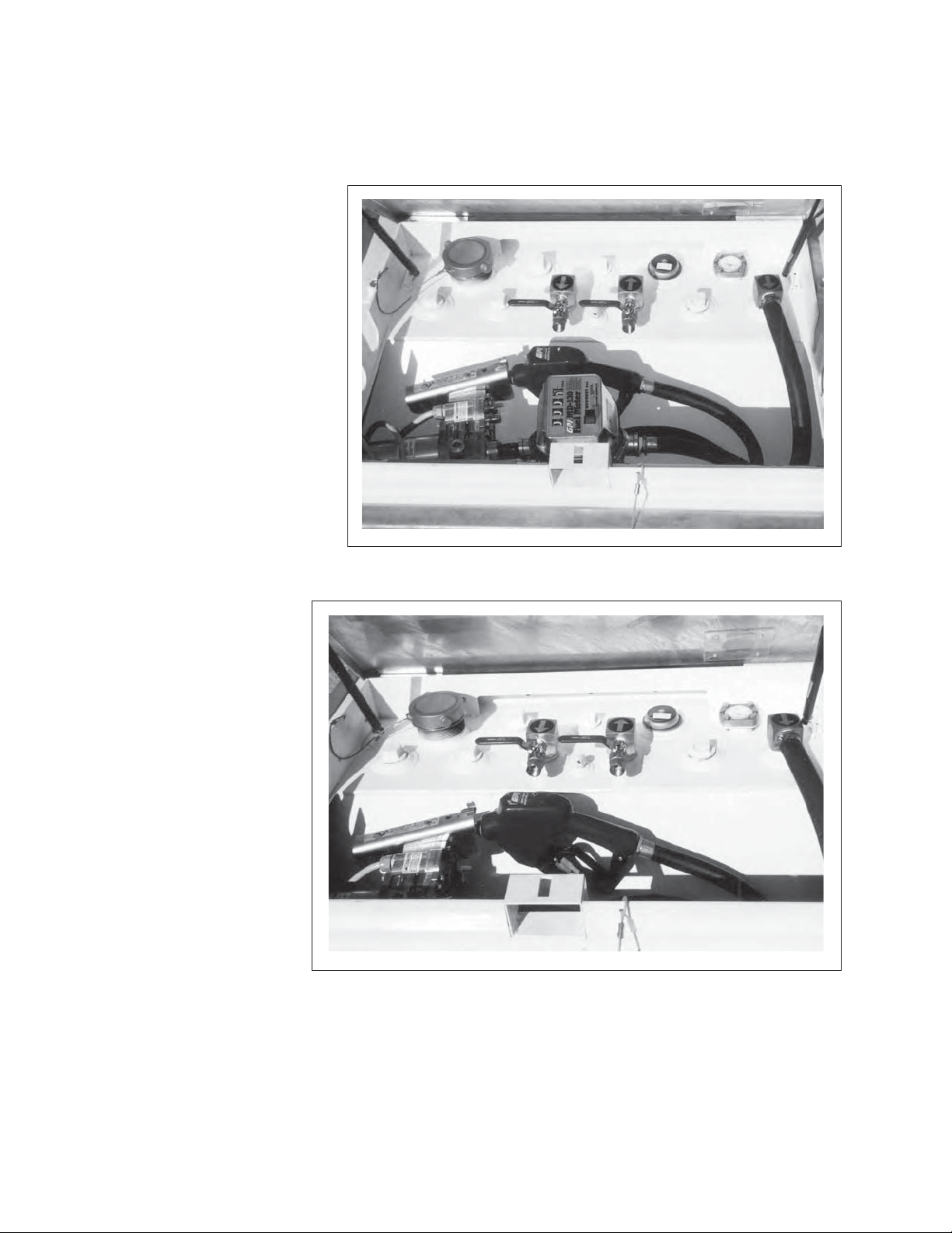
3. Fuel Gauge:
This gauge shows the amount of fuel in the
tank. Watch this gauge when filling the tank.
Do not fill more than 95% to prevent spillage
and allow for expansion.
4. Fuel Meter (Optional):
This meter measures the
volume of fuel being transferred by the hose and
nozzle. Depress the reset
button on top to zero the
gauge when required.
3
4
Fig. 4 FUEL METER (OPTIONAL)
5. Shut-Off Valves:
The TransCube is
designed with a line
for drawing fuel out of
the tank and a line for
returning the unused
fuel from the remote
engine. Turn the valve
handle at right angles
to the line to turn the
valves off. Align with
the line to open the
valve. Always turn
the valves off when
not using the lines or
when moving the unit.
6. Optional Outlets:
The TransCube is
designed with additional outlets that can
Fig. 5 INSIDE COVER
be used to connect to
additional feed lines.
Always mount shut-off valves to the lines
when connecting to new feed lines.
6
6
6
55
6
6
14
Page 23

. FIELD USE
OPERATING SAFETY
Please remember it is important that you
read and heed the safety signs on the Tran-
sCube. Clean or replace all safety signs if
they cannot be clearly read and understood.
They are there for your safety, as well as the
safety of others. The safe use of this tank is
strictly up to you, the operator.
Use only for the transport of diesel fuel for
refueling equipment or stand-by generators.
Keep the tank level when filling.
Fill only with a hand-held trigger nozzle.
Do not spill fuel on the ground or in the tank.
Do not smoke when refueling. Keep sparks,
flames and hot material away from fuel and
TransCube.
The TransCube is designed to efficiently and ef-
fectively transfer, transport and refuel equipment
in any location. It meets and exceeds all Canadian and U.S. DOT fuel transporting requirements
and has UN certification. These IBC’s are built to
U.S. Standard Code of Federal Regulations (CFR)
part 49 and are updated by annual tests. Max in
USA 793 gallons.
Do not over fill. 95% is the maximum legal
limit.
Always replace filler cap and turn pump off
(lever down) when refueling finished.
Store diesel hose and nozzle inside outer
tank.
Close all valve outlets and lock lid when
transporting on public highway.
Follow the regulations of the Transport of
Dangerous Goods.
Check for fluid in outer tank and empty
regularly - refer to maintenance manual for
detailed procedure.
Each owner and user of the TransCube should
review this manual as part of the regular training
and review procedure. Follow all instructions.
1. Owner Operator Responsibility
It is the responsibility of each owner, operator
or user to be familiar with all regulations that
apply to the equipment for transporting, filling,
transferring and refueling equipment. Perform
all tests per the regulations and maintain the
appropriate records and paperwork. Always
carry the required paperwork for the Transport
of Dangerous Goods. Be sure everyone is
properly trained and licensed to use or transport the TransCube. Do not smoke around
unit. Do not allow others to smoke around
unit.
Page 24
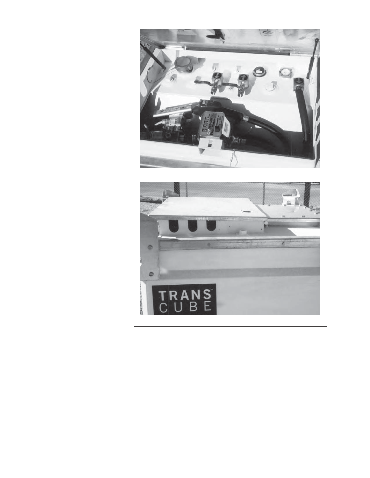
2. Venting:
a. Each tank is designed
with a stainless steel
and polyethylene pressure/vacuum relief vent
with elastomer seals
set at 3 psi. Maintain in
good condition. Replace vent if damaged
in any way. Replace
vent at the 60 month
test.
b. The fill cap is designed
with a 3 inch NPS stain-
less steel fusible (viton)
ring that would melt
when the temperature
reaches 250°F. Keep
it in good condition.
Replace cap if it is dam-
aged in any way.
c. The outer tank is
vented to atmosphere
through the hose slots
under the lid. Do not
obstruct in any way.
b
a
Inner
c
16
Outer
Fig. 6 LEVELING
Page 25
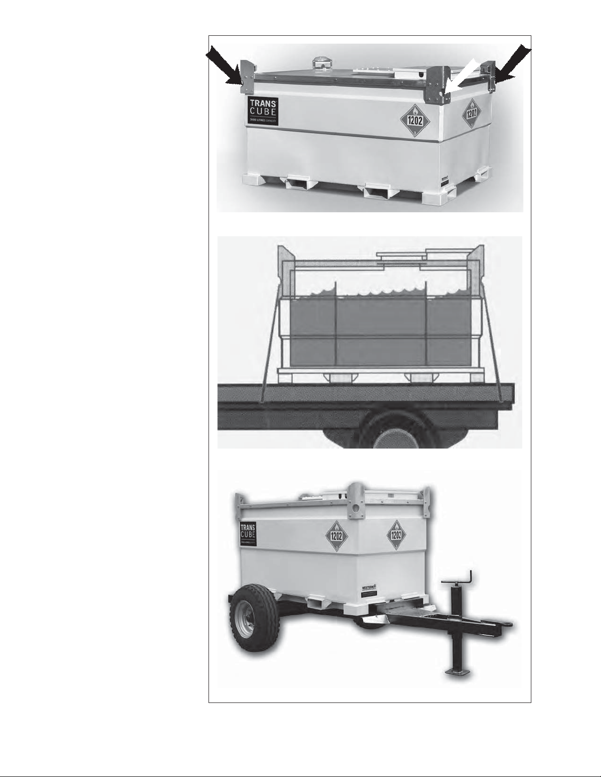
3. Securement for Transport:
The frame is designed
with brackets on the top
corners to anchor the
tie-downs when transporting. Do not transport
TransCube unless it is
securely tied-down to the
vehicle frame.
The TransCube must be
securely attached to its
means of transport, be it
a custom trailer, flat-bed
trailer or skid.
Brackets
Schematic
Trailer
Fig. 7 MOUNTED ON CUSTOM TRAILER
17
Page 26
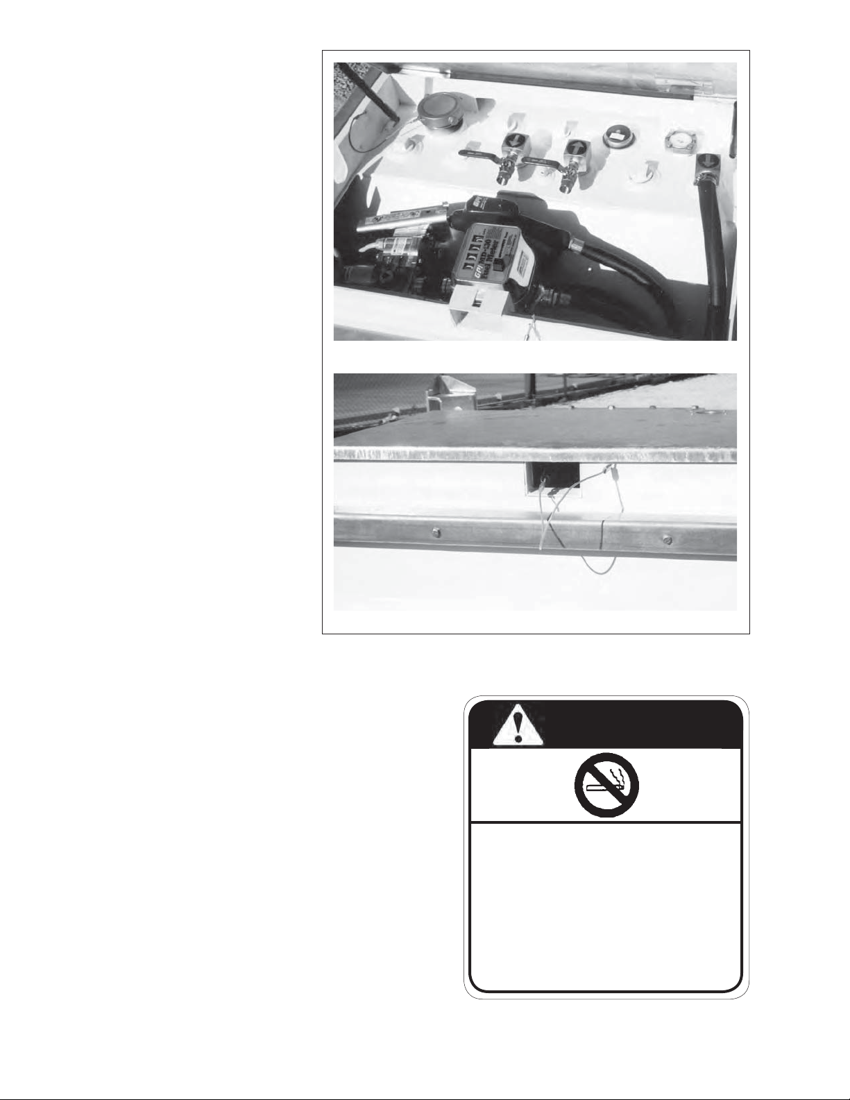
Filling TransCube:
4.
A 3 inch fill cap is located on
the top of the tank and is used
to fill the tank. Turn the cap to
open the tank for filling. Open
the cap slowly to release any
build-up of pressure due to
extreme temperatures. Close
and tighten cap when filling
is completed. Follow this
procedure when filling tank:
a. Level the tank or the vehi-
cle that it is mounted on.
b. Loosen fill cap and lay to
the side.
NOTE
The cap is tethered to
the frame with a steel
cable to prevent it from
falling between the
tanks. Keep cable in
good working condition.
Do not disconnect.
b
Filling
c. Fill the tank with a hand-
held nozzle.
IMPORTANT
Do not direct connect.
Take care not to spill
any fuel.
d. Watch the fuel gauge on tank while filling
to only fill to 95% capacity. 95% is the
legal capacity for the TransCube.
e. Close and tighten fill cap.
Fig. 8 FILLING
NOTE
Hand tighten fill cap and
then tighten another
1/4 turn to minimize the
chance of leakage.
f. Close and lock the hatch lid.
Hatch Lid Locked
DANGER
FIRE HAZARD
NO SMOKING
To prevent serious injury or death
from fire:
• Do not smoke when refueling.
18
• Keep sparks, flames and hot material
away from fuel and fuel tank.
TC0207
Page 27
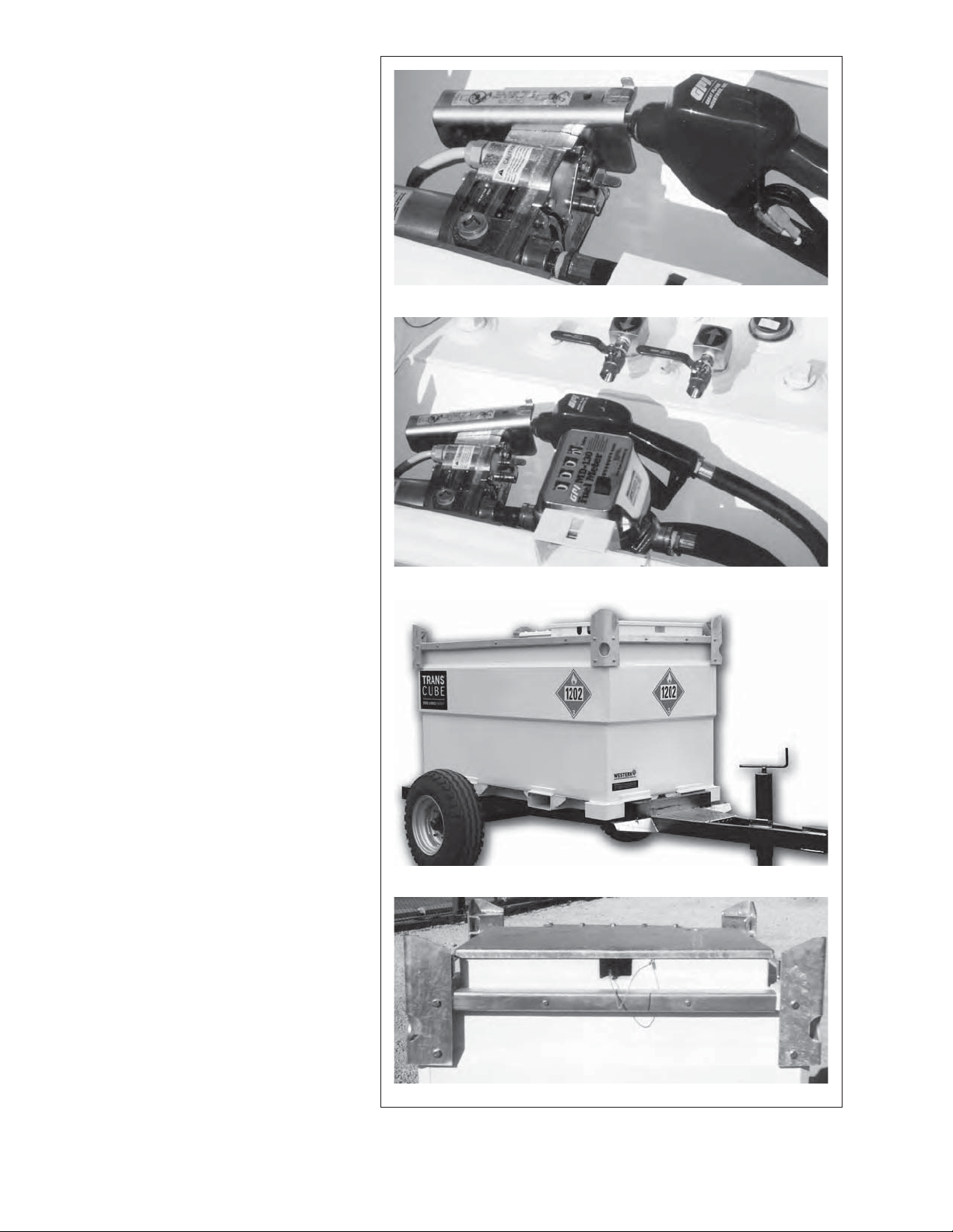
5. Closure for Transport:
The TransCube must be securely
closed prior to moving or transporting to minimize the chance of
spilling fuel.
Follow this procedure when pre-
paring for transport:
a. Turn the pump off by moving
the control lever down.
IMPORTANT
The closure systems
nearest to the contents
of the IBC should be
closed first.
b. Turn the generator port
valves off.
c. Close and tighten fill cap.
d. Close or plug all auxiliary
lines, hoses or other connec-
tors with the plugs provided
with the tank.
e. Stow the hose and hand held
nozzle under the cover.
f. Close and lock hatch-lid on
the outer tank.
Pump Off
Nozzle Stowed
Fig. 9 TRANSPORT
Trailer
Lid Lock
19
Page 28
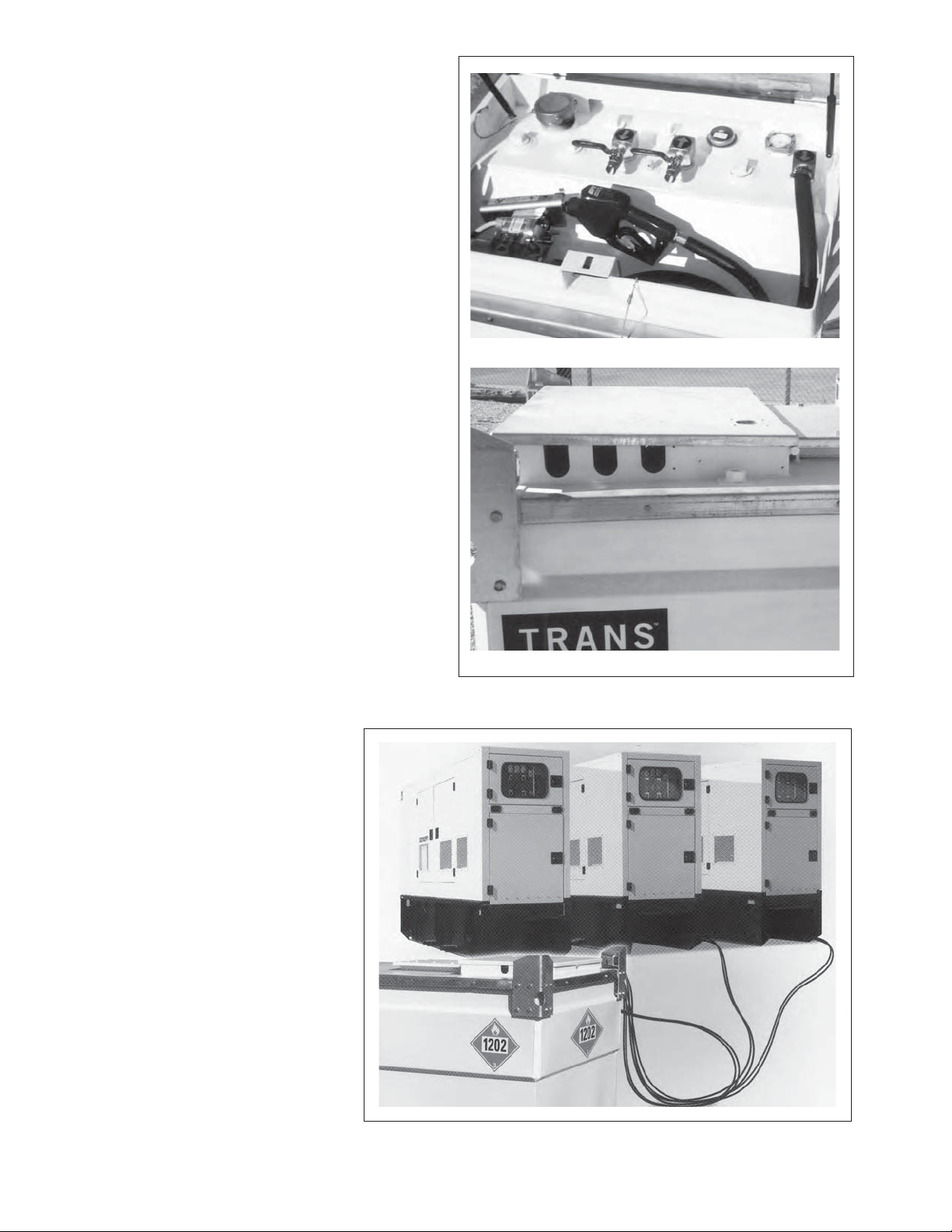
6. Generator Standby:
The TransCube is designed to be used to
provide fuel to generator sets or any other
power unit requiring fuel.
Follow this procedure when connecting as
a fuel supply to an engine:
a. Place TransCube in a level area adja-
cent to the engine requiring fuel.
b. Install quick couplers into the tank
outlets appropriate for your application.
The feed or return ports are marked
with directional arrows.
NOTE
Use teflon tape on the
threads to prevent leaking at
the connection.
c. Use connector components with NPT
threads.
d. Thread the power unit fuel line hoses
through the access slots on each side
of the frame.
e. Connect to the quick couplers on the
tank outlets.
IMPORTANT
It is recommended that a
fuel filter be installed in
the intake line to remove any contaminants
from the system prior to
entering the engine fuel
system.
Valves
Slots
Fig. 10 FUEL LINES
f. Open tank valves and
start engine.
Close and lock lid to pre-
g.
vent anyone from tampering with the fueling equipment.
h. Check the fuel gauge and
refill the tank when required to prevent running
out.
i. Turn valves off, discon-
nect power, disconnect
couplers, and lock lid
when TransCube is not
20
being used.
Fig. 11 SUPPLY FUEL
Page 29
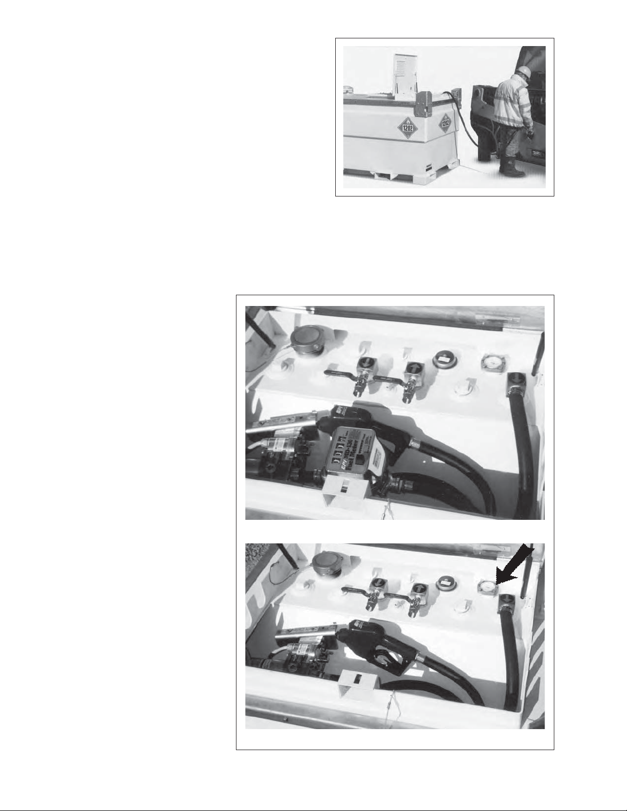
7. Refueling:
The
f. Connect a power supply to the pump (mini-
i.
TransCube works well as a tank to refuel other
tanks, machines or equipment. Review the pump
manual prior to using the pump. Follow this procedure when refueling:
a. Refer to Step 4 (pg. 18) "Filling TransCube".
b. Transport the TransCube to the refueling area.
c. Unlock and open hatch lid.
d. Pull out refueling hose and nozzle.
e. Extend it to the tank needing to be refueled.
mum 20 amp rating).
g. Turn the pump on.
h. Use the hand-held nozzle
to transfer the fuel.
Turn the pump off when
the refueling is completed.
Fig. 12 FILLING TANK
IMPORTANT
Do not spill fuel into the
interstice (bund). Wipe
up any spills.
j. Disconnect the power to
the pump.
NOTE
Use the optional fuel
meter to monitor how
much fuel is being transferred or use the fuel
gauge.
k. Store the hose into the
bund and hook the nozzle to the storage bracket.
l. Close and lock the hatch
lid.
Fuel Meter (Optional)
m. Move to the next refu-
eling location.
Fig. 13 COVER OPEN
Fuel Gauge
21
Page 30
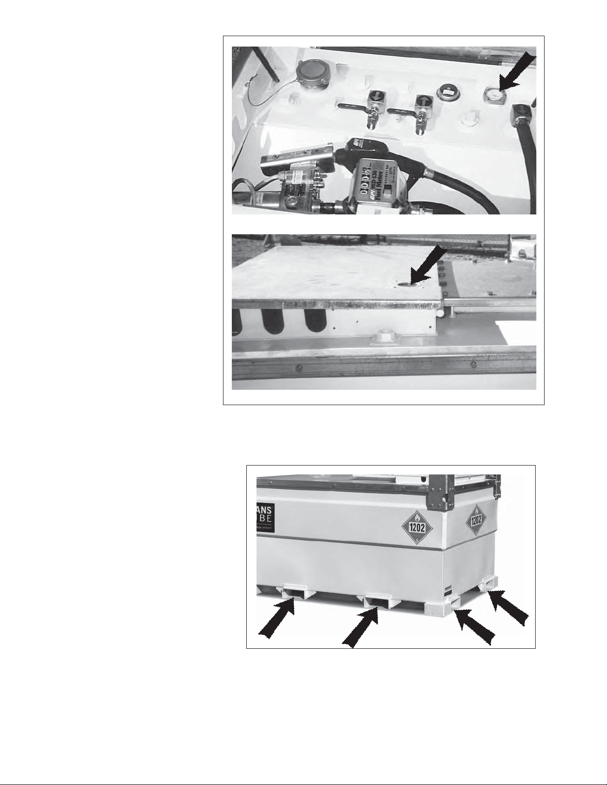
8. Fuel Gauge:
The TransCube is designed
with a gauge that displays
the amount of fuel in the
tank. Always watch the
gage when filling the tank to
prevent over-filling.
The lid is designed with
an access hole above the
gauge to allow for monitoring the fuel level without the
need to open the lid.
Gauge
Forklifts:
9.
The base of the
signed with pockets on all sides
to allow access for the forks of
a forklift. A forklift can pick up
the tank from any side when it is
necessary to raise or maneouver
the unit.
TransCube is de-
Access Hole
Fig. 14 FUEL GAUGE
Fig. 15 FORKLIFT POCKETS
22
Page 31
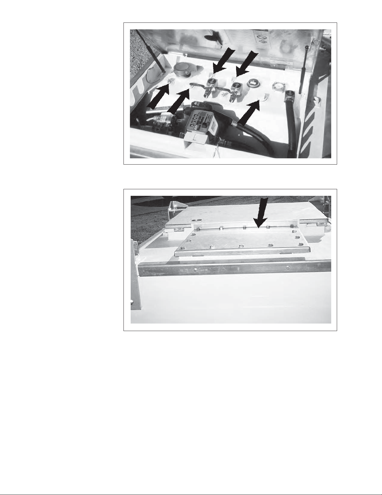
10. Additional Outlets:
The top of the tank is
designed with extra
outlets to allow ad-
ditional engines or
machines to use the
tank as a source for
fuel. Install the feed
and return lines, down
tube check valve,
strainer and return
port into the outlets.
Mount shut-off valves
to each line to allow
the line to be turned
off when required.
Manway Access
11.
Cover:
The top is designed
with a cover to provide access to the in-
side of the tank when
required. Remove
the anchor bolts
and cover when it is
required to enter the
tank. Always install
a new gasket when
re-installing cover.
Fig. 16 ADDITIONAL OUTLETS
Fig. 17 MANWAY ACCESS COVER
23
Page 32
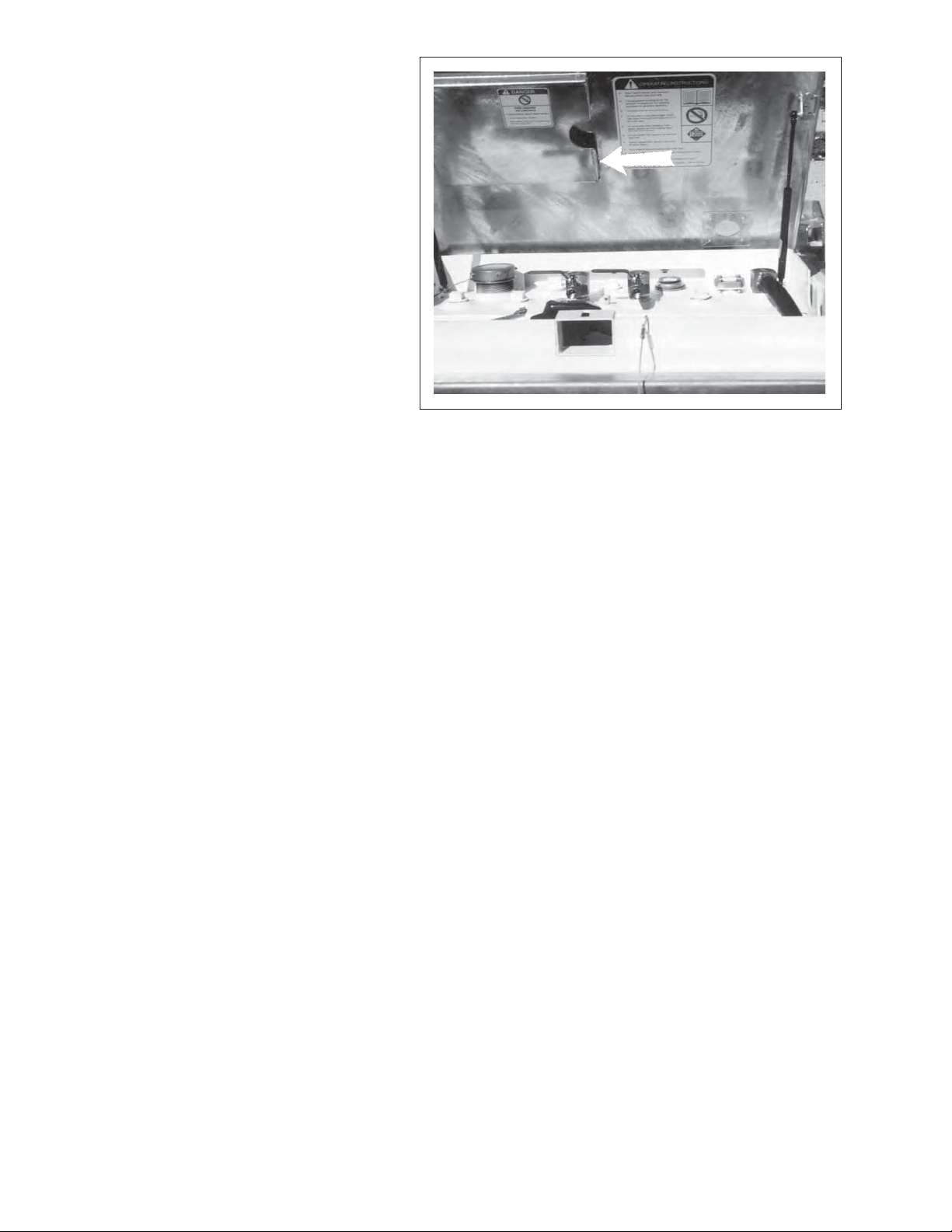
12. Records:
• Each owner or operator is
responsible to obtain records
from the periodic inspections
and re-testing of the IBC Tran-
sCube and keep them with the
unit. Place your record and
operator's manual in the vinyl
sleeve provided on the shelf
above the inner tank.
• Keep the records available
with the unit and make them
available to Government Representatives or Inspectors on
site when requested.
• A Record Card is provided
with the Documentation package to record the compulsory
60 month testing program at
a registered facility. The date
and test results must be recorded on
the card and stamped on the Specification Plate.
Fig. 18 SLEEVE FOR DOCUMENTS
13. Damage:
• Anything that is transported from location to location can be in an accident
and damaged or damaged during
use. Any time the inner or outer tank
is damaged, impaired or compro-
mised in any way, the tanks should be
repaired and then retested up to 3 psi.
• Diesel fuel is a hazardous material
and must be treated as such. Do not
use the unit if it is damaged and take
a chance with contaminating your
worksite or the environment. Repair
and retest prior to re-using.
14. Parts and Service:
• Transport of Dangerous Goods requires that parts replacement must be
of the same specification or equivalent. It is recommended that genuine
replacement parts be obtained from
Western Environmental Canada Inc.
such as nitrile gaskets, fusible fill
caps, pressure/vacuum relief vent and
gauges.
Call 1-866-539-3781. Please have
your model number, serial number of
your TransCube model ready and the
parts description. Do not return parts.
24
Page 33
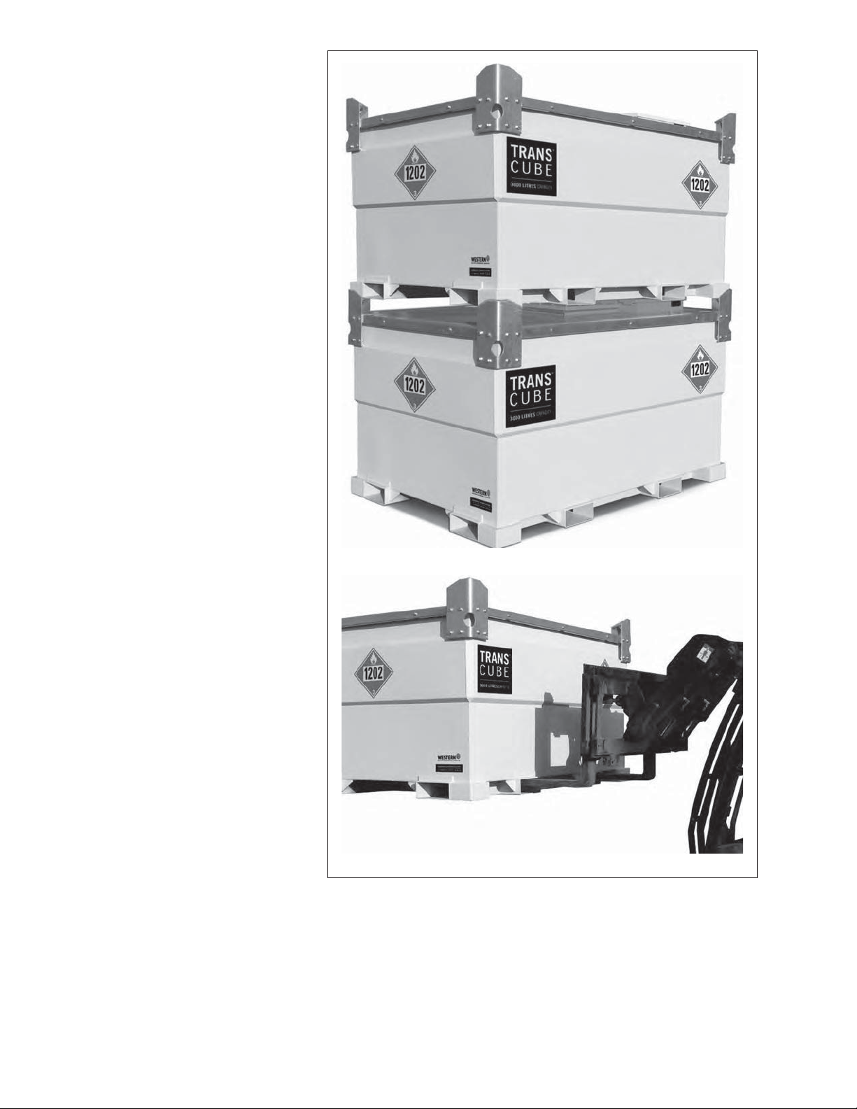
15. Storage:
• The frame of the
• Use only a hoist or
TransCube is de-
signed with the structural strength to allow
stacking 2 high when
full and 3 high when
empty. Always mate
the corner brackets
together to stabilize
the pile.
forklift with the required lift capacity to
raise, lower or stack
the tanks.
Stored
Forklift
Fig. 19 STORAGE AND HANDLING
25
Page 34
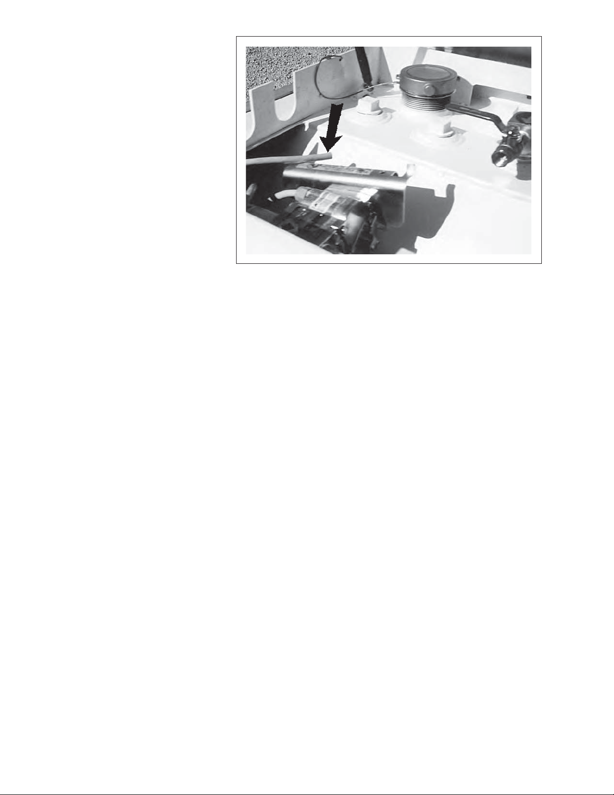
16. Power Source:
• When a pump is fitted, the unit comes
from the factory with
a power cord to the
pump. It is recommended that 20 amp
rated battery clamps
on the power cord to
attach to battery terminals on the equipment
being refueled (12 volt
pump only).
Fig. 20 POWER CORD
17. Monitoring:
The best results are obtained when the TransCube is monitored, inspected, checked and
tested per this recommended list. Keep and
maintain these records.
a. During Fuel Transfers:
Someone needs to be in attendance
when filling the TransCube or transferring
fuel. Always manually hold the nozzle
and depress the trigger when transferring
into or out of the TransCube. Visually
monitor the fuel gauge while transferring fuel to prevent spilling or overfilling.
Remember the maximum legal capacity is
95% full. Do not direct connect.
b. Daily Checklist (While In Use):
It is recommended that the tank and all
of its components be maintained in good
condition at all times. Develop a check-
list to use when verifying the condition
of each component or system. It should
include but not be limited to:
• Fuel level.
• Pipes, tubes, valves and couplers.
• Hoses, nozzles and connections.
• Leaks.
• Bent, broken or damaged components.
• Electrical wires, terminals and connections.
Stop leaks, repair problems and replace
any broken components with genuine
replacement parts or their equivalent.
26
Page 35
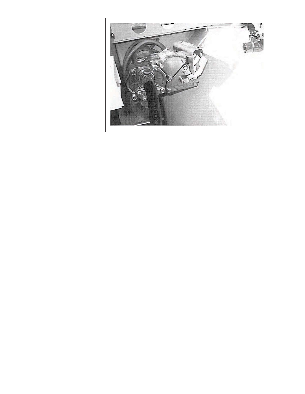
c. Wee ly and efore
Transportin
Visually check
the interstice
bund to verify
that there have
been no leaks
from the primary
tank or any spills
during fuel transfers. If it has any
sludge or liquid in
it, hand pump it
into an approved
container, seal
it and dispose
of it in accordance with local
regulations. Do
not pour on the
ground or put in
drains.
Fi . INTERSTICE
If severe sludge or trash formed in the
interstice, it is recommended that the
inner tank be removed and the outer
tank be completely washed out. Do
not take chances with contaminating
the workplace or the environment.
d. Monthly
ubricate the door hinge and lock.
Clean out pump and line filters includ-
ing strainer.
Visually check tank, hoses, valves,
pump and other components for
cracks, corrosion and leakage.
Correct all deficiencies before start-
ing. Stop leaks. Make repairs using
only genuine replacement parts or
their equivalent.
e. Compulsory 0 Month Testin at a
Re istered Facility
The Transport of Dangerous Goods
requires I C's to be leak proof tested
and inspected internally and externally
at a Government Registered Facility with
the results being recorded on the Record
Card and the date stamped on the Speci-
fication Plate.
. Preparation for 0 Month Testin
Cleaning - prior to being leak tested or inspected, the I C shall be
a. Thoroughly drained of all previous lad-
ings.
b. Interior washed to remove previous lad-
ings.
c. Interior rinsed to remove washing materi-
als.
d. Interior dried to remove liquids.
e. Exterior washed to remove previous lad-
ings, foreign material, labels and adhesives from all exterior components of the
IC.
The TransCube is manufactured so that it
is easy to dismantle for cleaning, servicing,
repairs, inspections, etc.. Empty the tank, and
follow instructions outlined on the following
page.
Page 36
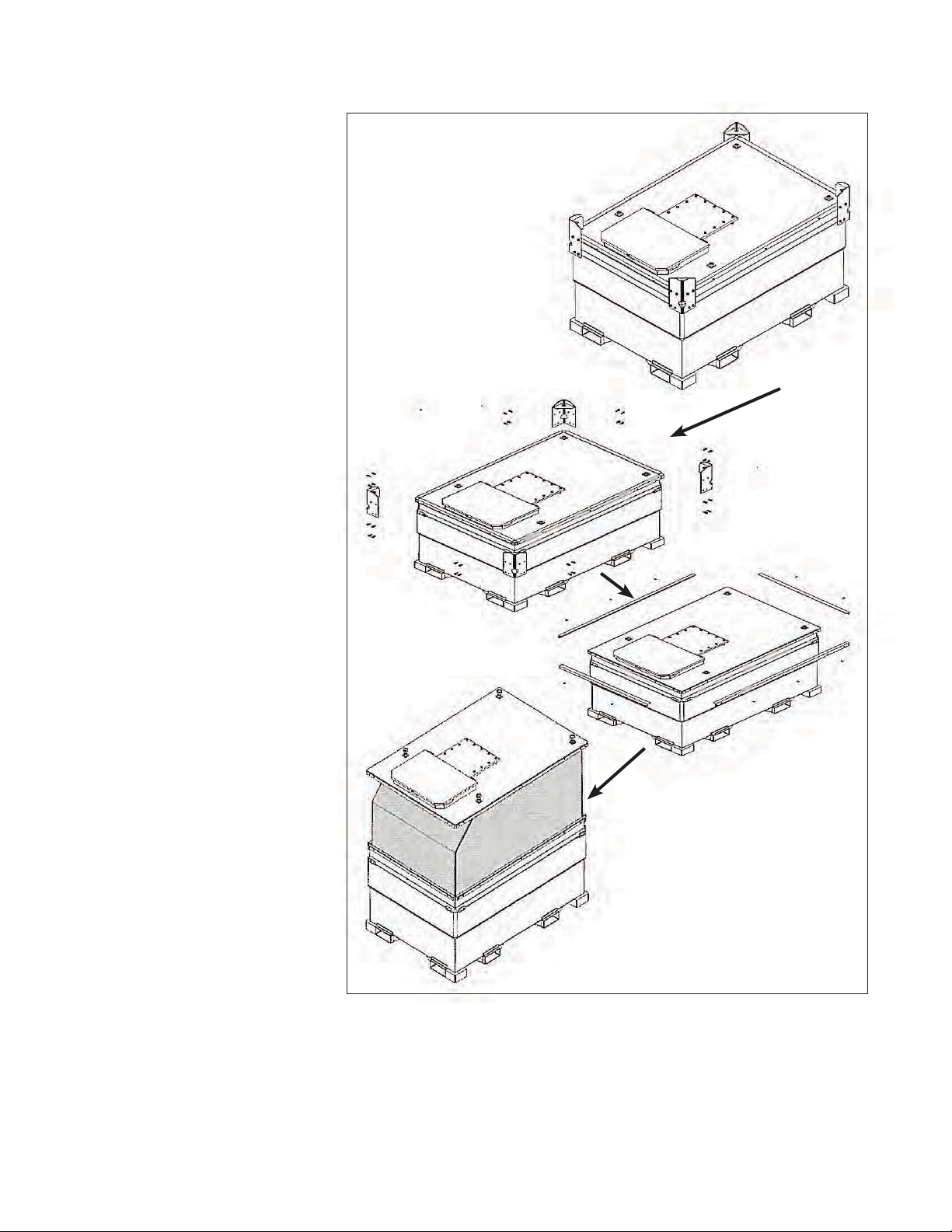
. CLEANING
Each owner and user of the
TransCube should review this
manual as part of the regular
training and review procedure.
Follow all instructions.
. Remove corner sockets,
edging strip and install lifting eyes.
. With the inner tank emptied
of fuel, lift it out using the
lifting eyes.
. Clean the inside of the outer
tank bund . Remove all
debris and liquids.
. Remove the access cover,
lift up the back end of the
inner tank, and draw off any
residue with a pipe inserted
into the tank.
. If it is necessary to enter the
tank, care should be taken,
and a safe working procedure drawn up and follow it.
With Tan Empty
. Remove the corner lift-
ing stacking sockets.
NOTE
Mark or identify each
component prior to removal to allow reassembly in the same location.
. Remove the edging
strip along the top of
each side.
Dismantle
. Screw in lift-
ing eyes into
sockets on
the top of the
tank.
Drain Plu s
. ressure wash out the tank,
drain tank, then dry. An
internal inspection can now
be made.
It is recommended the leak test
is carried out after the internal
inspection. Replace pressure
vacuum relief valve with a plug
for the leak test. Reassemble
the tank and install a new gasket around the access cover.
Secure using x boltnut assemblies. Tighten to
ft. lbs. torque to ensure there is
no leakage.
Install a new pressure vacuum relief
valve that is available from Western.
eak proof test at kpa for min-
utes.
Reassemble
. Attach lifting system and lift
straight up.
. Clean the inside of the bund.
. Reassemble in the reverse or-
der.
. Tighten fasteners to their speci-
fied torque.
Fi . INNER TAN REMOVAL
eep records of testing with the unit
at all times.
Page 37
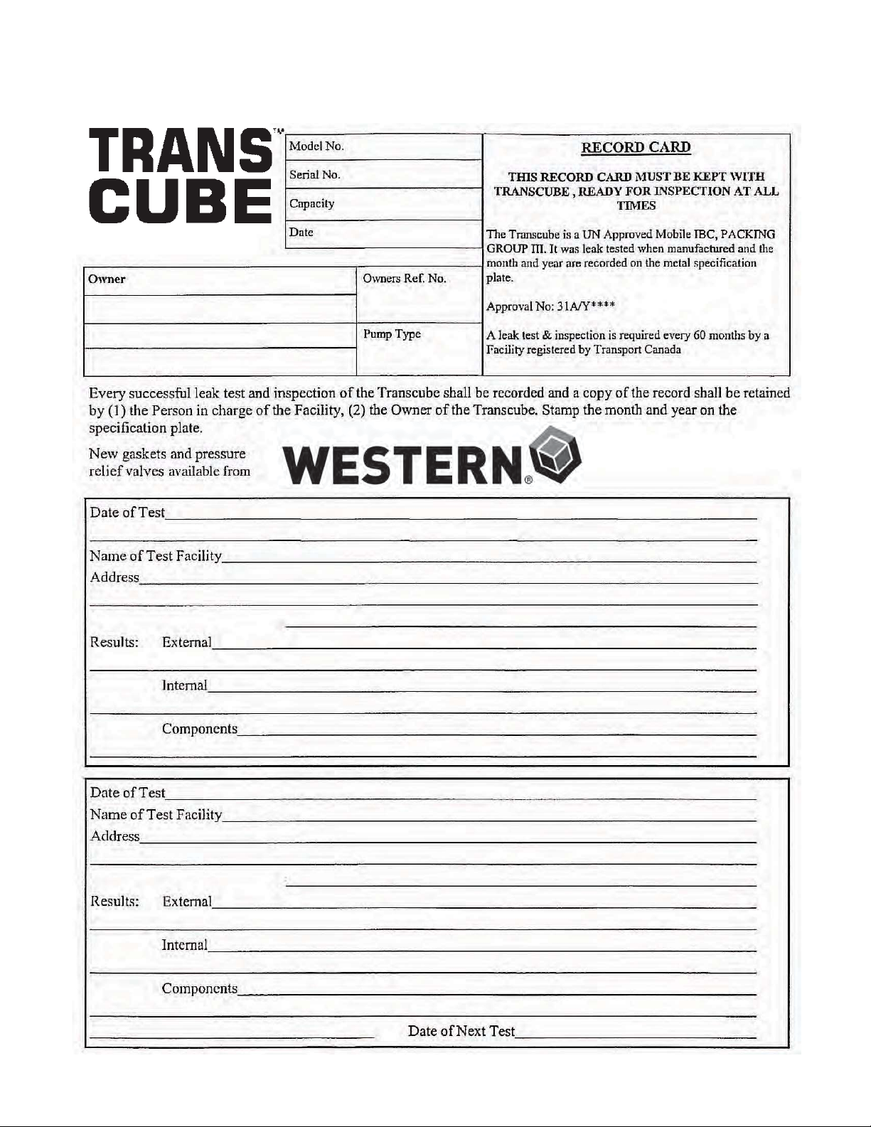
RECORD FORM
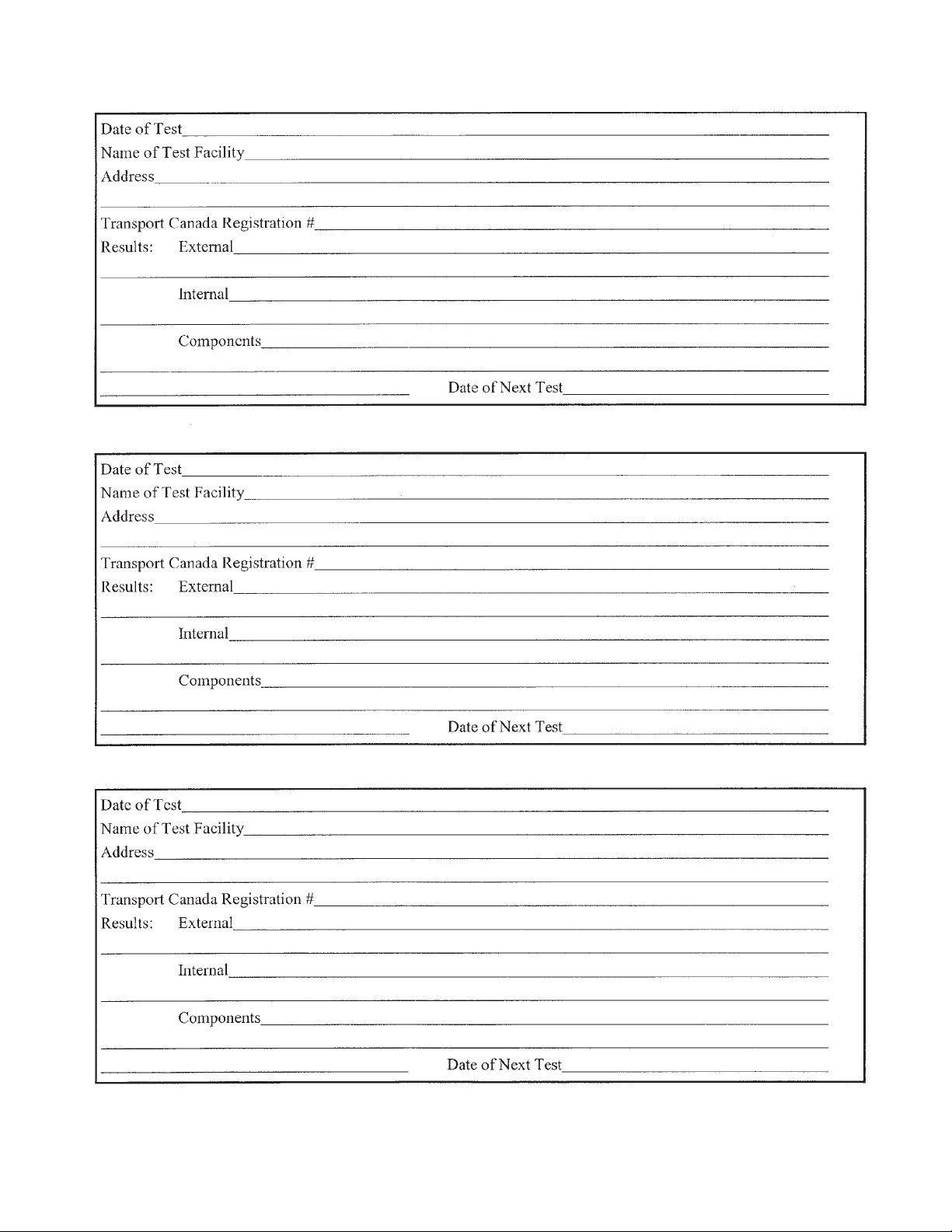
Use this form to keep track of all tank inspections and testing. Make copies of the next pages for your
records.
Specification Double Wall Mobile
Diesel Fuel Tank
Western
290 Quarry Road
Milford, CT
Toll Free: -
Global
: - F: -
Page 38
30
Page 39

6 TROUBLE SHOOTING
The TransCube is a double walled tank for transporting diesel fuel from one location to another. It is a
simple and reliable system that requires minimal maintenance.
In the following section, we have listed many of the problems, causes and solutions to the problems that
you may encounter.
If you encounter a problem that is difficult to solve, even after having read through this trouble shooting
section, please call your local Western distributor or dealer. Before you call, please have this Operator's
Manual from your unit and serial number ready.
PROBLEM CAUSE SOLUTION
Pump will not run. No power. Connect power wires to 12 volt
power source.
Pump off. Turn pump on.
Diesel fuel in interstice. Loose fitting. Tighten fitting.
Leaking coupler. Replace coupler.
Over filling tank. Watch fuel gauge when filling.
Do not over fill tank.
Water in the interstice. Leaving latch lid open Keep latch lid closed.
to weather.
31
Page 40

7 SPECIFICATIONS
7.1 MECHANICAL
DIMENSIONS
IMPERIAL / METRIC (MM)
LENGTH WIDTH HEIGHT
45 1/4" (1155) 45 1/4" (1155) 33" (838)
45 1/4" (1155) 45 1/4" (1155) 52" (1320)
86 1/4" (2190) 45 1/4" (1155) 52" (1320)
90 1/2" (2300) 59 1/8" (1500) 52" (1320)
90 1/2" (2300) 90 1/2" (2300) 52" (1320)
32
WEIGHT LBS. (Kg)
EMPTY FULL
IMP. US LITER
MODEL CAPACITY
965 LBS (437) 1901 LBS (862)
GAL. GAL.
05TCG 110 132 500
1118 LBS (508) 2994 LBS (1358)
10TCG 220 264 1000
1825 LBS (828) 5574 LBS (2528)
2153 LBS (972) 7765 LBS (3522)
3567 LBS (1618) 12235 LBS (5550)
20TCG 440 528 2000
30TCG 660 792 3000
50TCG 1040 1247 4725
SPECIFICATIONS SUBJECT TO CHANGE WITHOUT NOTICE
*ALL WEIGHTS ARE APPROXIMATE
Page 41
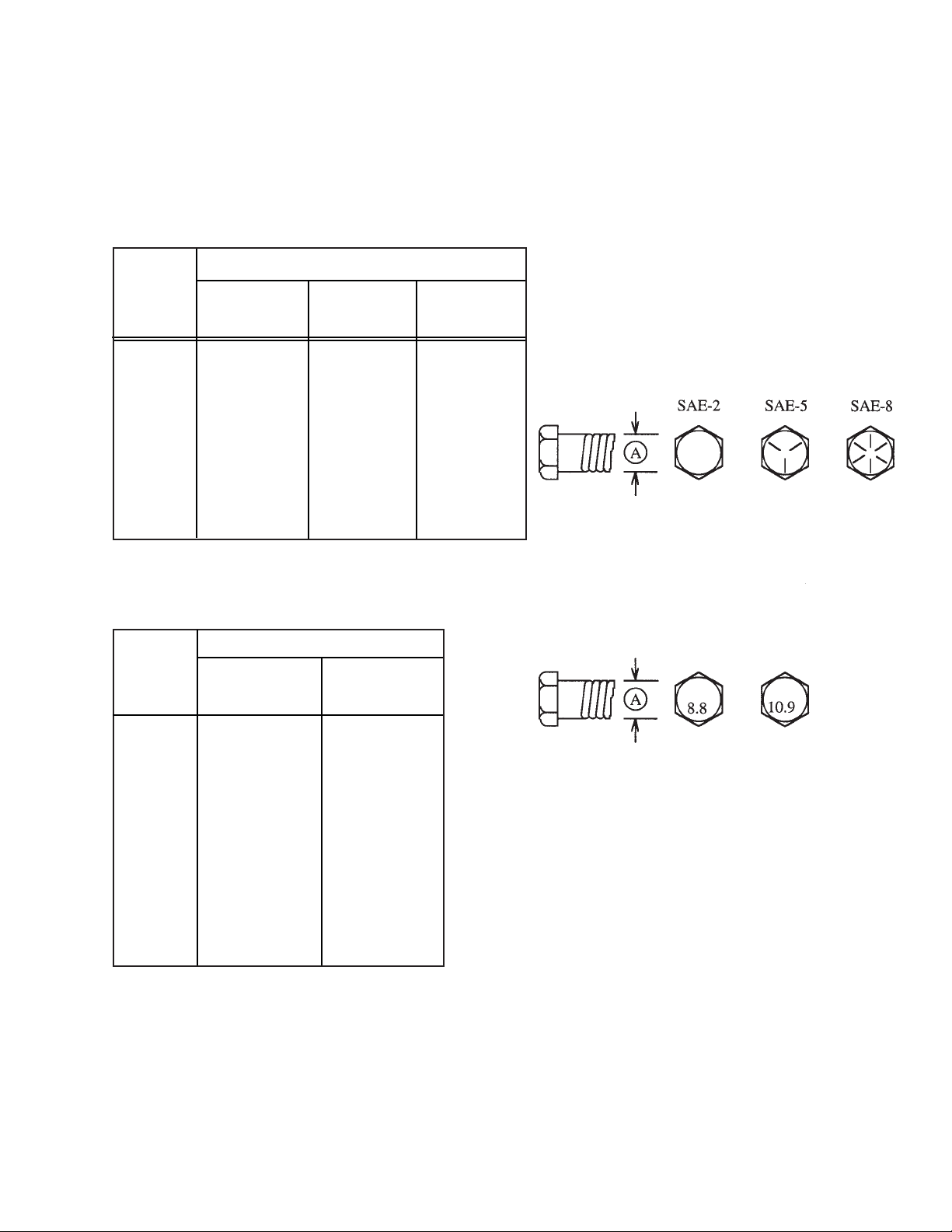
7.2 BOLT TORQUE
CHECKING BOLT TORQUE
The tables shown below give correct torque values for various bolts and capscrews. Tighten all bolts to
the torques specified in chart unless otherwise noted. Check tightness of bolts periodically, using bolt
torque chart as a guide. Replace hardware with the same strength bolt.
ENGLISH TORQUE SPECIFICATIONS
Bolt
Bolt Torque*
Diameter
"A"
1/4"
5/16"
3/8"
7/16"
1/2"
9/16"
5/8"
3/4"
7/8"
1"
METRIC TORQUE SPECIFICATIONS
SAE 2
(N.m) (lb-ft)
8
13
27
41
61
95
128
225
230
345
6
10
20
30
45
60
95
165
170
225
SAE 5
(N.m) (lb-ft)
12
25
45
72
110
155
215
390
570
850
Bolt Torque*
Bolt
Diameter
"A"
8.8
(N.m) (lb-ft)
(N.m) (lb-ft)
9
19
33
53
80
115
160
290
420
630
10.9
SAE 8
(N.m) (lb-ft)
17
36
63
100
155
220
305
540
880
1320
12
27
45
75
115
165
220
400
650
970
M3
M4
M5
M6
M8
M10
M12
M14
M16
M20
M24
M30
M36
Torque figures indicated above are valid for non-greased or non-oiled threads and heads unless otherwise specified. Therefore, do not grease or oil bolts or capscrews unless otherwise specified in this
manual. When using locking elements, increase torque values by 5%.
* Torque value for bolts and capscrews are identified by their head markings.
.5
3
6
10
25
50
90
140
225
435
750
1495
2600
.4
2.2
4
7
18
37
66
103
166
321
553
1103
1917
1.8
4.5
9
15
35
70
125
200
310
610
1050
2100
3675
1.3
3.3
7
11
26
52
92
148
229
450
774
1550
2710
33
Page 42

7.3 HYDRAULIC FITTING TORQUE
TIGHTENING FLARE TYPE TUBE FITTINGS *
1. Check flare and flare seat for defects
that might cause leakage.
2. Align tube with fitting before tightening.
3. Lubricate connection and hand tighten
swivel nut until snug.
4. To prevent twisting the tube(s), use two
wrenches. Place one wrench on the
connector body and with the second
tighten the swivel nut to the toque
shown.
* The torque values shown are based on
lubricated connections as in reassembly.
TIGHTENING O-RING FITTINGS *
Tube
Size
OD
(in.)
3/16
1/4
5/16
3/8
1/2
5/8
3/4
7/8
Nut Size
Across
Flats
(in.)
7/16
9/16
5/8
11/16
7/8
1
1-1/4
1-3/8
Torque
Value*
(N.m) (lb-ft)
8
12
16
24
46
62
102
122
6
9
12
18
34
46
75
90
Recommended
Turns To Tighten
(After Finger
Tightening)
(Flats) (Turn)
1
1
1
1
1
1
3/4
3/4
1/6
1/6
1/6
1/6
1/6
1/6
1/8
1/8
1. Inspect O-ring and seat for dirt or
obvious defects.
2. On angle fittings, back the lock nut
off until washer bottoms out at top of
groove.
3. Hand tighten fitting until back-up
washer or washer face (if straight
fitting) bottoms on face and O-ring is
seated.
4. Position angle fittings by unscrewing
no more than one turn.
5. Tighten straight fittings to torque
shown.
6. Tighten while holding body of fitting
with a wrench.
* The torque values shown are based on lubricated connections as in reassembly.
Tube
Size
OD
(in.)
3/8
7/16
1/2
9/16
3/4
7/8
1-1/16
1-3/16
1-5/16
1-5/8
1-7/8
Nut Size
Across
Flats
(in.)
1/2
9/16
5/8
11/16
7/8
1
1-1/4
1-3/8
1-1/2
1-7/8
2-1/8
Torque
Value*
(N.m) (lb-ft)
8
12
16
24
46
62
102
122
142
190
217
6
9
12
18
34
46
75
90
105
140
160
Recommended
Turns To Tighten
(After Finger
Tightening)
(Flats) (Turn)
2
2
2
2
2
1-1/2
1
1
3/4
3/4
1/2
1/3
1/3
1/3
1/3
1/3
1/4
1/6
1/6
1/8
1/8
1/12
34
Page 43
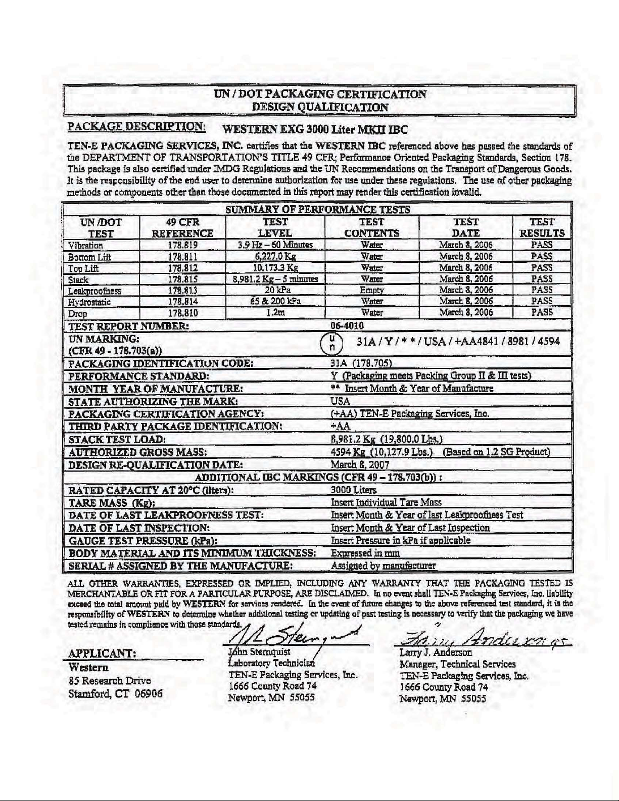
. TYPICAL UN TEST CERTIFICATE
3
Page 44

Page 45

INDE
I
PAGE
Introduction......................................................
O
Operation.......................................................
Cleaning ...................................................
Controls ....................................................
Field Use ..................................................
Machine reak-In .....................................
Machine Components...............................
re-Operation Checklist ...........................
To the New Operator or Owner.................
R
Record Form..................................................
S
Safety ..............................................................
Equipment Safety Guidelines .....................
General Safety ...........................................
Maintenance Safety....................................
Operating Safety.........................................
reparation.................................................
Safety Signs ...............................................
Safety Training............................................
Sign-Off Form.............................................
Storage Safety............................................
Transport Safety.........................................
Safety Sign ocations......................................
Specifications ................................................
olt Torque ...............................................
ydraulic Fitting Torque............................
Mechanical ...............................................
T
Trouble Shooting ...........................................
PAGE
3
Page 46

Page 47

Page 48

ISSUE DATE: MARCH 2010
PART #: TC0213US
Western
290 Quarry Road
Milford, CT 06460
T | 203-847-4300
F | 203-847-4310
E | [email protected]
W| www.transcube.net/us
Global Inc.
WESTERN INTERNATIONAL, INC.
18 Lois Street
Norwalk, CT 06851
T: 203 847 4300
F: 203 847 4310
E: info@western.us.com
 Loading...