

Page 1

WESTERN PRODUCTS, P.O. BOX 245038, MILWAUKEE, WI 53224-9538
FORM NO. 63551
September 1, 1999
LSX BLADE
ASSEMBLY INSTRUCTIONS
LSX Blade No. 63472
A, Q & L Box No. 63470
Hydraulics Box No. 56545
Headlamp Kit No. 61540 or 61550
CAUTION
See your WESTERN® outlet for application
recommendations. The Selection List has
specific vehicle and snowplow requirements.
A DIVISION OF DOUGLAS DYNAMICS, L.L.C.
Page 2

TABLE OF CONTENTS
SAFETY . . . . . . . . . . . . . . . . . . . . . . . . . . . . . . . . . . 1
Safety Definitions . . . . . . . . . . . . . . . . . . . . . . . . . . 1
Safety Labels . . . . . . . . . . . . . . . . . . . . . . . . . . . . . 1
Safety Precautions . . . . . . . . . . . . . . . . . . . . . . . . . 1
Personal Safety . . . . . . . . . . . . . . . . . . . . . . . . . . . 2
Fire and Explosion . . . . . . . . . . . . . . . . . . . . . . . . . 2
Ventilation . . . . . . . . . . . . . . . . . . . . . . . . . . . . . . . . 2
Battery Safety . . . . . . . . . . . . . . . . . . . . . . . . . . . . . 3
Hydraulic Safety . . . . . . . . . . . . . . . . . . . . . . . . . . . 3
Torque Chart . . . . . . . . . . . . . . . . . . . . . . . . . . . . . 3
ASSEMBLY INSTRUCTIONS . . . . . . . . . . . . . . . . . . 4
Plow Assembly with LSX Blade . . . . . . . . . . . . . . . 4
Assembling Quadrant to Blade . . . . . . . . . . . . . 5
Assembling A-Frame to Quadrant . . . . . . . . . . . 5
Assembling Stand to A-frame . . . . . . . . . . . . . . 6
Assembling Lift Frame to A-frame . . . . . . . . . . . 6
Assembling Lift Channel and Hydraulic Unit
to Lift Frame . . . . . . . . . . . . . . . . . . . . . . . . . 7
Assembling Hydraulic Fittings and Hoses . . . . . 7
Assembling Light Brackets and Headlamps . . . 8
Assembling Hydraulic Unit Wiring . . . . . . . . . . . 9
Assembling Battery Cable to Motor . . . . . . . . . 10
Blade Guide Assembly Installation Instructions . . 11
Form No. 63551
September 1,1999
Page 3
SAFETY
SAFETY DEFINITIONS
WARNING
Indicates a potentially hazardous situation that,
if not avoided, could result in death or serious
personal injury.
CAUTION
Indicates a situation that, if not avoided, could
result in minor personal injury and/or damage to
product or property.
NOTE: Identifies tips, helpful hints and
maintenance information the owner/operator
should know.
SAFETY LABELS
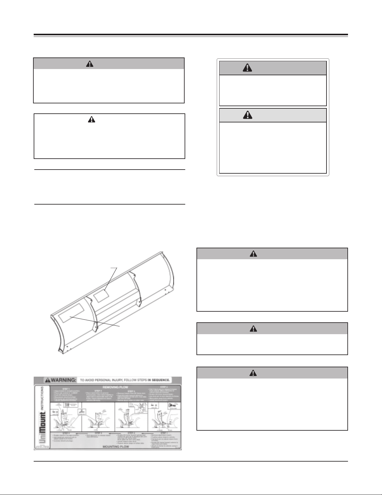
Become familiar with and inform users about the
warning and instruction labels on the back of the blade.
Warning and Caution Label
Warning and Caution Label
WARNING
LOWER BLADE WHEN VEHICLE IS PARKED.
REMOVE BLADE ASSEMBLY BEFORE PLACING VEHICLE
ON HOIST.
DO NOT EXCEED GVWR OR GAWR INCLUDING BLADE
AND BALLAST.
CAUTION
READ OWNER'S MANUAL BEFORE OPERATING OR
SERVICING SNOWPLOW.
TRANSPORT SPEED SHOULD NOT EXCEED 45 MPH.
REDUCE SPEED UNDER ADVERSE TRAVEL
CONDITIONS.
PLOWING SPEED SHOULD NOT EXCEED 10 MPH.
SEE YOUR WESTERN OUTLET FOR APPLICATION
RECOMMENDATIONS.
SAFETY PRECAUTIONS
Improper installation and operation could cause
personal injury, and/or equipment and property damage. Read and understand labels and the Owner’s
Manual before installing, operating, or making adjustments.
WARNING
Lower blade when vehicle is parked.
Temperature changes could change hydraulic
pressure, causing the blade to drop
unexpectedly or damaging hydraulic
components. Failure to do this can result in
serious personal injury.
59900
Form No. 63551
Instruction Label
Instruction Label
WARNING
Remove blade assembly before placing vehicle
on hoist.
WARNING
Keep well clear of the blade when it is being
raised, lowered or angled. Do not stand
between the vehicle and blade or directly in
front of blade. If the blade hits you or drops on
you, you could be seriously injured.
(Continued on next page.)
1
September 1,1999
Page 4
SAFETY
SAFETY PRECAUTIONS (CONTINUED)
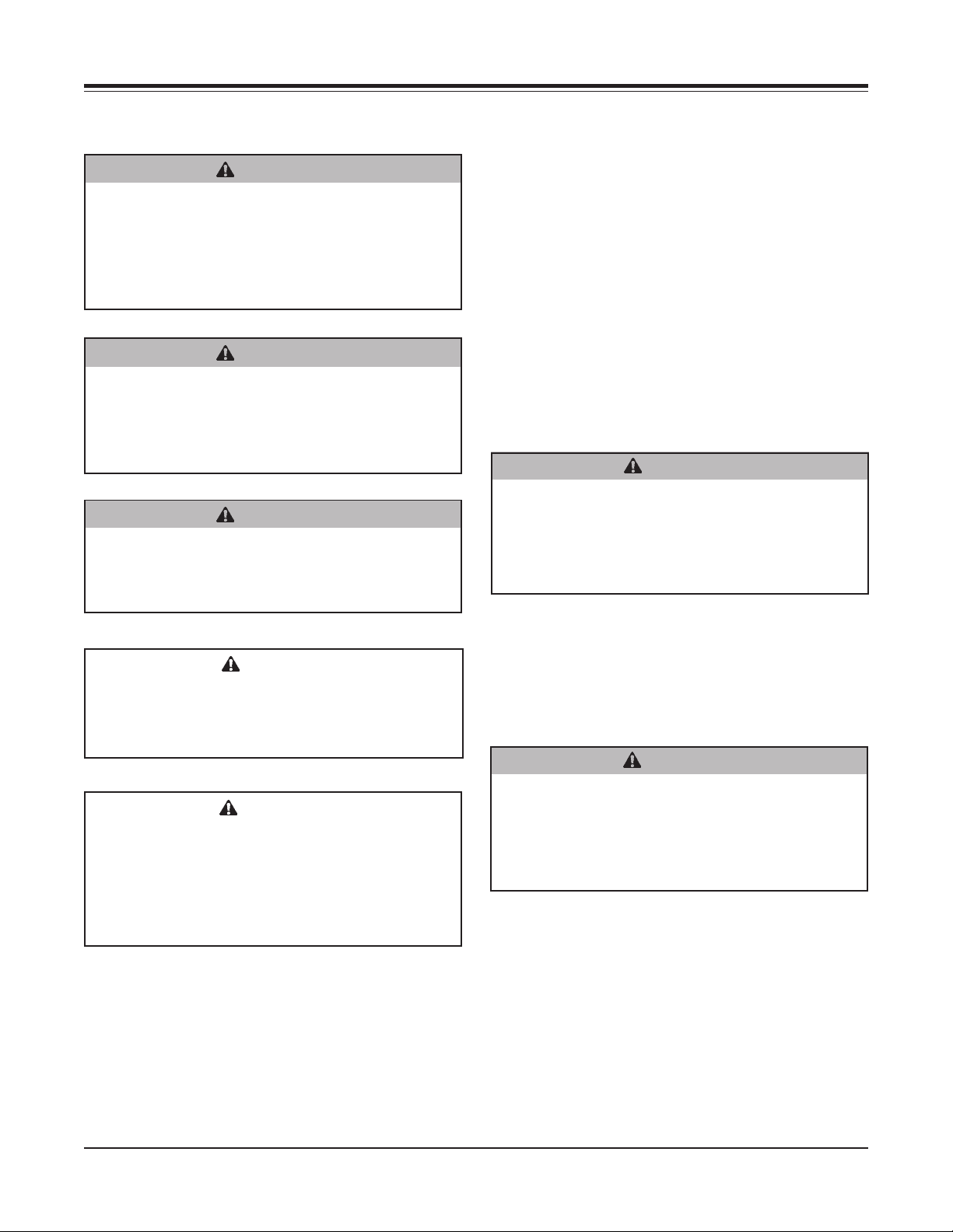
WARNING
The driver shall keep bystanders clear of the
blade when it is being raised, lowered or angled.
Do not stand between the vehicle and the blade
or within 8 feet of a moving blade. A moving or
falling blade could cause personal injury.
WARNING
Keep hands and feet clear of the blade and
A-frame when mounting or removing the
snowplow. Moving or falling assemblies could
cause personal injury.
WARNING
Do not exceed GVWR or GAWR including blade
and ballast. The rating label is found on driverside vehicle door cornerpost.
PERSONAL SAFETY
• Wear only snug-fitting clothing while working on
your vehicle or snowplow.
• Do not wear jewelry or a necktie, and secure
long hair.
• Wear safety goggles to protect your eyes from
battery acid, gasoline, dirt and dust.
• Avoid touching hot surfaces such as the engine,
radiator, hoses and exhaust pipes.
• Always have a fire extinguisher rated BC handy,
for flammable liquids and electrical fires.
FIRE AND EXPLOSION
WARNING
Gasoline is highly flammable and gasoline
vapor is explosive. Never smoke while working
on vehicle. Keep all open flames away from
gasoline tank and lines. Wipe up any spilled
gasoline immediately.
CAUTION
Refer to the current selection list for minimum
vehicle recommendations and ballast
requirements.
CAUTION
To prevent accidental movement of the blade,
always turn the ON/OFF switch to OFF
whenever the snowplow is not in use. The
control indicator light will turn off.
Be careful when using gasoline. Do not use gasoline to
clean parts. Store only in approved containers away
from sources of heat or flame.
VENTILATION
WARNING
Vehicle exhaust contains deadly carbon
monoxide (CO) gas. Breathing this gas, even in
low concentrations, could cause death. Never
operate a vehicle in an enclosed area without
venting exhaust to the outside.
Form No. 63551
2
September 1,1999
Page 5
SAFETY
BATTERY SAFETY
CAUTION
Batteries normally produce explosive gases
which can cause personal injury. Therefore, do
not allow flames, sparks or lit tobacco to come
near the battery. When charging or working
near a battery, always cover your face and
protect your eyes, and also provide ventilation.
Batteries contain sulfuric acid which burns skin,
eyes and clothing.
Disconnect the battery before removing or
replacing any electrical components.
CAUTION
Always disconnect the battery before removing
or replacing electrical components such as a
motor relay or battery cable.
HYDRAULIC SAFETY
WARNING
Hydraulic oil under pressure could cause skin
injection injury. If you are injured by hydraulic
oil, get medical attention immediately.
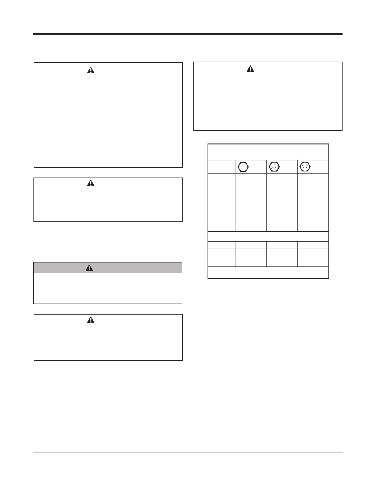
TORQUE CHART
CAUTION
Read instructions before assembling. Bolts
should be finger tight until instructed to tighten
according to the torque chart. Use standard
methods and practices when attaching
snowplow including wearing safety glasses
during cutting, drilling and welding.
Recommended Fastener Torque
Chart (Ft.-Lb.)
Size
1/4-20
5/16-18
3/8-16
3/8-24
7/16-14
1/2-13
9/16-12
5/8-11
3/4-10
7/8-9
1-8
SAE
Grade 2
6
11
19
24
30
45
66
93
150
202
300
Metric Grade 8.8 (Ft.-Lb.)
Size TorqueSize
M 6
M 8
M 10
These torque values apply to mount assembly fasteners
Torque
7
17
35
except those noted in the instruction.
M 12
M 14
M 16
SAE
Grade 5
9
18
31
46
50
75
110
150
250
378
583
SAE
Grade 8
13
28
46
68
75
115
165
225
370
591
893
60
95
155
CAUTION
Do not mix different types of hydraulic fluid.
Some fluids are not compatible and may cause
performance problems and product damage.
• Always inspect hydraulic components and hoses
before using. Replace any damaged or worn parts
immediately.
• If you suspect a hose leak,
hand to locate it. Use a piece of cardboard or
wood.
Form No. 63551
DO NOT
use your
3
September 1,1999
Page 6
ASSEMBLY INSTRUCTIONS
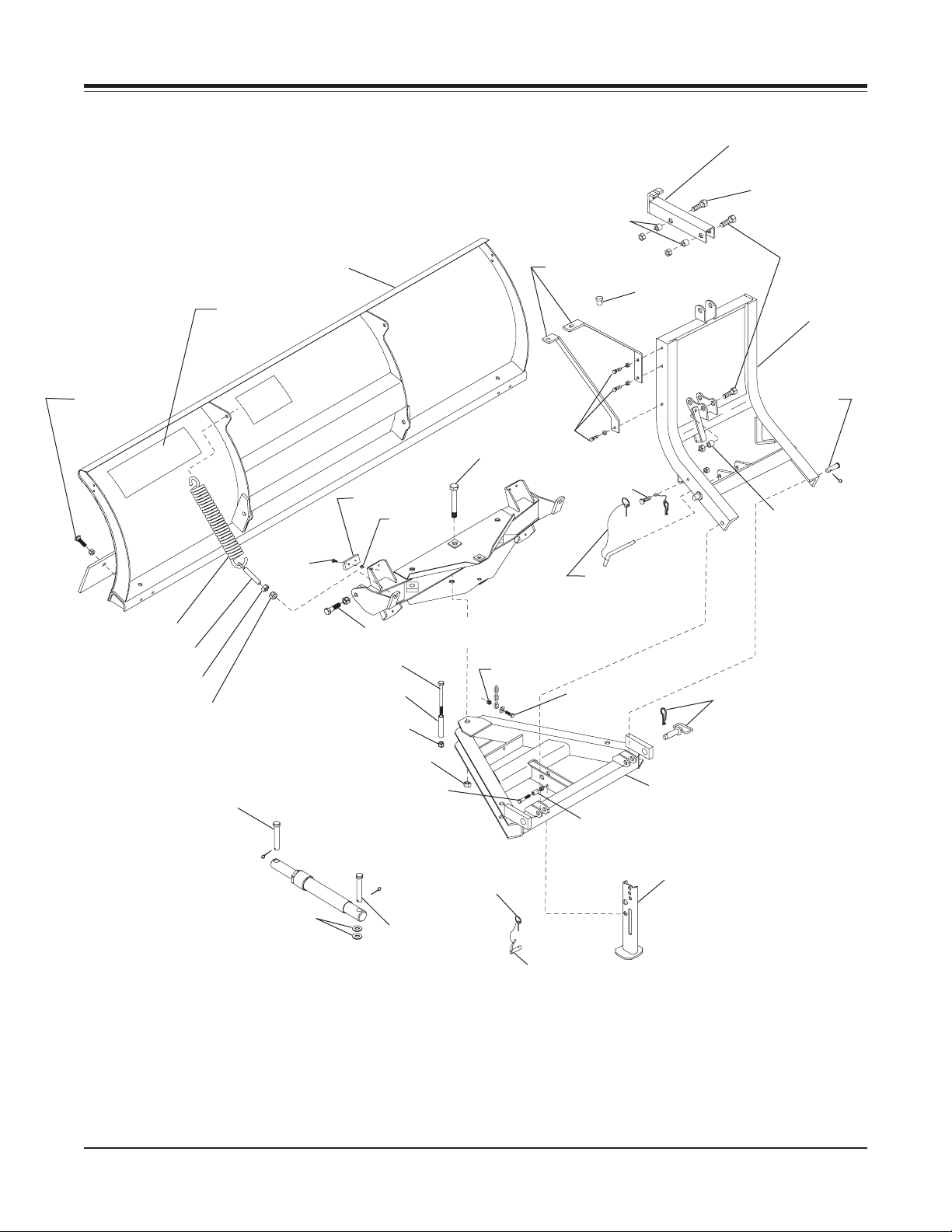
PLOW ASSEMBLY WITH LSX BLADE
7'-2" LSX Blade
UniMount®
Instruction
Label
1/2" x 1-3/4"
Carriage
Bolt
Bumper
1/4" x 3/4"
Bolt
Trip Spring
Eyebolt
5/8" Nut
5/8" Locknut
1/2" x 5-1/2" Bolt
Stop Bushing
1/2" Locknut
5/8" x 2-1/2" Bolt
3/4" Locknut
1/4"
Locknut
Light Brackets
3/8" x 1-1/4" Bolts
3/4" x 5-1/4"
Bolt
3/8" Locknut
3/4" x 1/2"
Spacers
Vinyl
Cap
1/4" x 3/4"
Bolt
1/2" x 5-1/2"
Stand Pin
Assembly
3/8" x 1-1/4"
Grade 5
Bolt
Lift Channel
3/4" x 3-1/4"
Bolt
3/4" x 3-3/4"
Bolt
Lift
Frame
5/8" x 2-1/4"
Clevis Pin
3/4" x 11/16"
Spacer
1" x 3-1/2"
Hitch Pin &
Hairpin Cotter
Form No. 63551
3/4" x 4-3/8"
Clevis Pin
3/4" Washers
3/8" x 2" Bolt
3/4" x 3-1/4"
Clevis Pin
3/16"
Linch Pin
Figure 1
4
A-frame
9/16" Spacer
Stand
5/8" x 2"
Stand Lock Pin Assembly
September 1,1999
Page 7
ASSEMBLY INSTRUCTIONS
Assembling Quadrant to Blade
WARNING
To avoid personal injury, follow steps in
sequence.
CAUTION
See your WESTERN® outlet for application
recommendations.
IMPORTANT: Read instructions before assembling.
Bolts should be finger tight until instructed to tighten.
Use standard methods and practices when attaching
the snowplow.
1. Lay blade face down on cardboard on the floor.
Assemble the quadrant to the blade with the
quadrant lugs straddling the center ribs. Secure
with two 5/8" x 2-1/2" bolts and locknuts. DO NOT
bend lugs by overtightening nuts.
Assembling A-frame To Quadrant
1. Insert A-frame into the quadrant channel aligning
A-frame noseplate hole with the center 3/4" hole in
the Quadrant channel. Insert a 3/4" x 5-1/4" bolt
from the top and secure with a locknut on the
bottom. DO NOT overtighten—A-frame should
pivot freely.
2. Align stop bushing with 1/2" holes in quadrant
plates. Secure using a 1/2" x 5-1/2" bolt and
locknut.
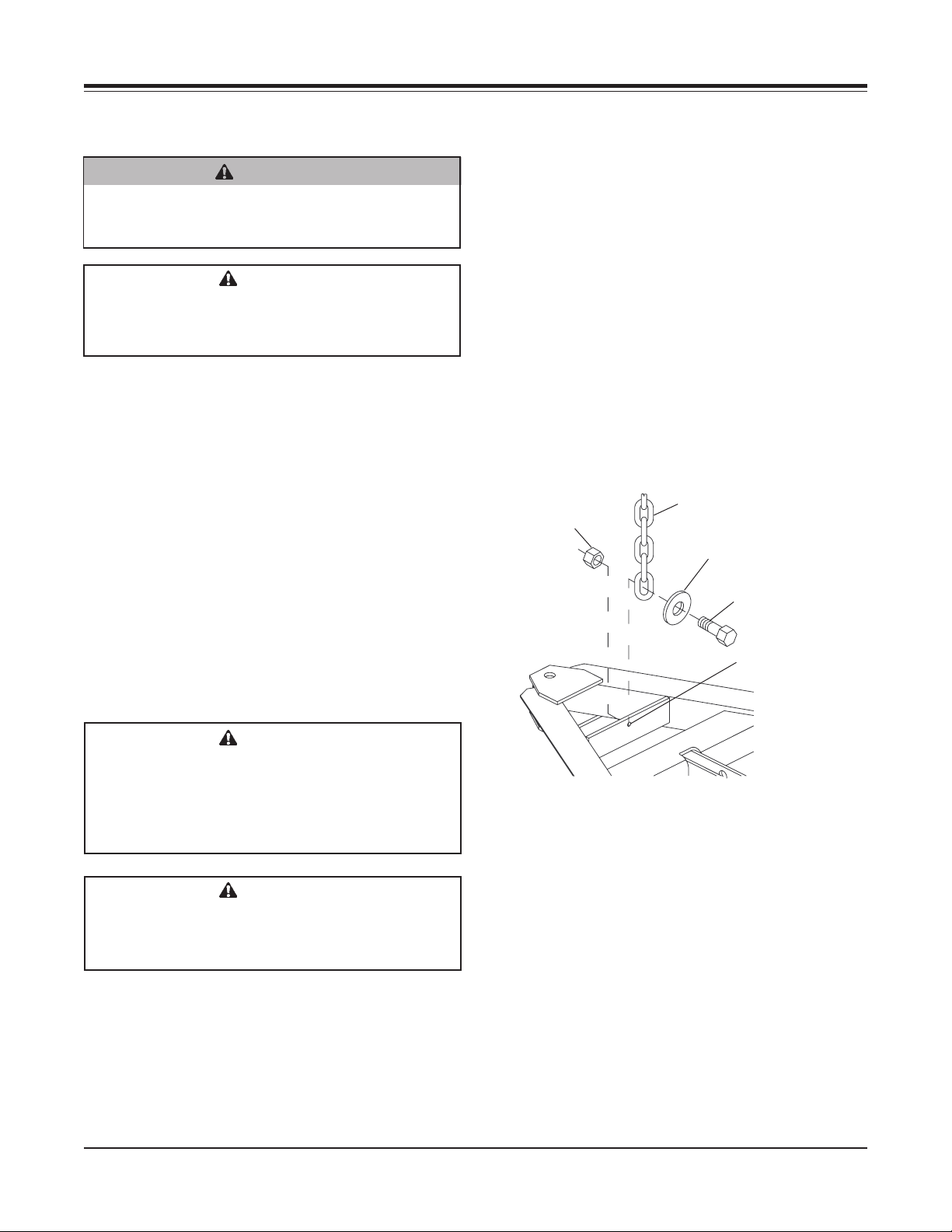
3. Use a 3/8” x 1-1/4” grade 5 bolt with 3/8" SAE flat
washer to attach end link of chain to hole in flat bar
on A-frame and secure with a locknut. Attach chain
to side of flat bar towards wide end of A-frame.
(See Figure 2.)
3/8"
Locknut
Chain
Flat Washer
2. Thread one 5/8" nut halfway down on each of the
two eyebolts. Hook a spring into the hole at the top
of each center rib. Hook an eyebolt to the other
end of each spring. Push the threaded end of each
eyebolt through the holes in the spring lugs on the
quadrant and install a locknut behind the lug.
CAUTION
Servicing the trip springs without special tools
and knowledge could result in personal injury.
See your authorized WESTERN® outlet for
service.
CAUTION
Over tightening springs will not increase blade
trip force and can damage the springs.
Adjust trip spring tension by tightening locknut
while preventing eyebolt rotation by holding across
flats using an adjustable wrench. Tighten only until
coils begin to separate. (Instruction sheet should
pass between second and third coils.) Lock in
place by tightening the locknut securely against the
lug while preventing the eyebolt from turning.
3/8" x 1-1/4"
Grade 5 Bolt
Hole in Flat Bar
on A-frame
Figure 2
Chain Attachment to Back of Flat Bar
4. Insert rod end of each Hydra-Turn® ram into
quadrant channel. Align rod holes with 3/4" holes in
quadrant and insert 3/4" x 4-3/8" grade 5 rivet.
5. Attach base end of each ram (pipe plug facing out)
to the side of A-frame with a 3/4" x 3-1/4" rivet.
Place two 3/4" washers under each ram base
inside A-frame channel.
Insert all rivets from the top and secure with cotter
pins.
Form No. 63551
5
September 1,1999
Page 8
ASSEMBLY INSTRUCTIONS
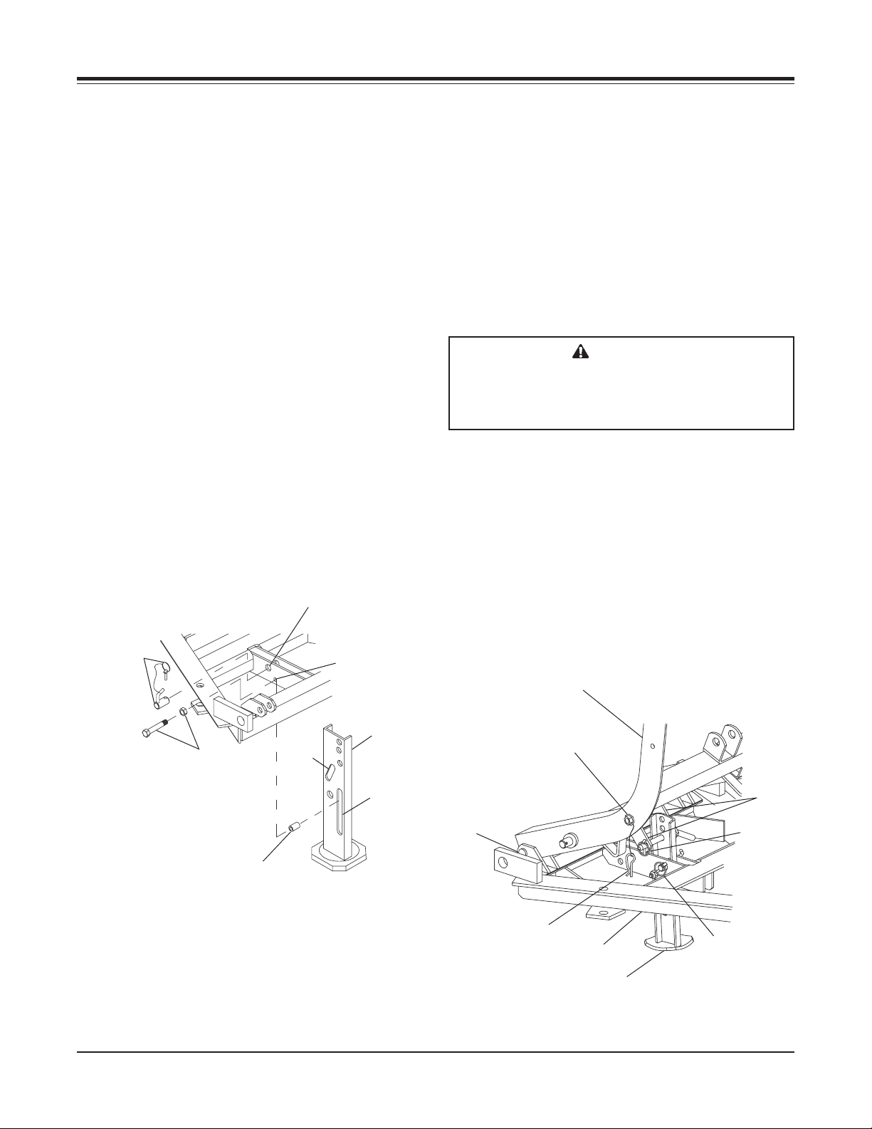
Assembling Stand To A-frame
If stand is already installed, proceed to Step 5 of this
section.
1. Position the stand next to the center bars of the
A-frame with the long slot towards the wide end of
A-frame.
2. Insert the 9/16" outside diameter spacer into the
top end of the long slot in the stand.
3. Holding spacer in place with a finger, insert the
stand between the A-frame center bars and align
spacer with small hole in center bars.
4. Secure spacer with a 3/8" x 2" bolt and locknut.
5. Hold stand perpendicular to A-frame. Align short
slot in stand with large hole in center bars, and
insert the 5/8" x 2" stand lock pin. Secure stand
lock pin with a 3/16" linchpin.
6. Tip the plow assembly into plowing position.
Assembling Lift Frame To A-frame
1. Lay lift frame on floor with curve up and ends of
side angles positioned next to wide end of A-frame.
Raise end of lift frame and align holes in side
angles between inner pairs of lugs on wide end of
A-frame.
2. Secure lift frame to A-frame lugs with two 5/8" x
2-1/4" clevis pins inserted from the outside towards
the center of the A-frame. Secure with cotter pins.
CAUTION
Never use a finger to check an alignment. If the
snowplow moves, your finger could be crushed.
3. Rotate lift frame to align holes in stand lugs to
bottom hole of three hole pattern in top of stand.
Secure with a 1/2" x 5" stand pin assembly using
3/16" linchpin.
5/8" x 2"
Stand Lock Pin
& 3/16"
Linchpin
Assembly
Assembling Stand to A-frame
3/8" x 2"
Bolt & Nut
9/16" OD
Spacer
Figure 3
Large Hole
in Center Bars
Short
Slot
Small Hole
in Center
Bars
Stand
Long
Slot
4. Assemble a hairpin cotter through one eyelet of the
6” lanyard. Attach the other end to the hole in the
lift frame located above the stacking stop bracket
using the 1/4" x 3/4” hex flange bolt and nut.
Lift Frame
Side Angle
1/4" x 3/4" Hex
Flange Bolt & Nut
5/8" x 2-1/4"
Clevis
Pin
(Insert
towards
center.)
Stand
Lugs
Stand Pin
Assembly
with 3/16"
Linch Pin
Lanyard &
Hairpin Cotter
A-frame
Stand
Lock Pin
Assembly
with 3/16"
Linch Pin
Assy
Figure 4
Lift Frame Pinned to A-frame and Stand
Form No. 63551
6
September 1,1999
Page 9
ASSEMBLY INSTRUCTIONS
Assembling Lift Channel and Hydraulic
Unit To Lift Frame
1. Place the hole end of the lift channel between the
lugs of the upper U-bracket on the lift frame. Insert
a 3/4" x 3-3/4" bolt and secure with a .50" long
spacer and jam locknut. DO NOT OVERTIGHTEN
- lift channel must pivot freely.
2. Position the hydraulic unit (found in hydraulics
box), with the nameplate towards the blade, and
with the base lug between the lugs of the lower
U-bracket on the lift frame. Attach with a 3/4" x
3-3/4" bolt, a .69 long spacer, and a jam locknut.
DO NOT OVERTIGHTEN - hydraulic unit must
pivot freely.
3. Align hole in hydraulic unit lift ram with hole near
hook on lift channel and attach with a 3/4"’ x 3-1/4"
bolt, a .50 long spacer, and a jam locknut. DO NOT
OVERTIGHTEN - lift channel must pivot freely.
4. Place second link of chain into hook of lift channel.
(Final chain adjustment will be made after plow is
mounted on vehicle.)
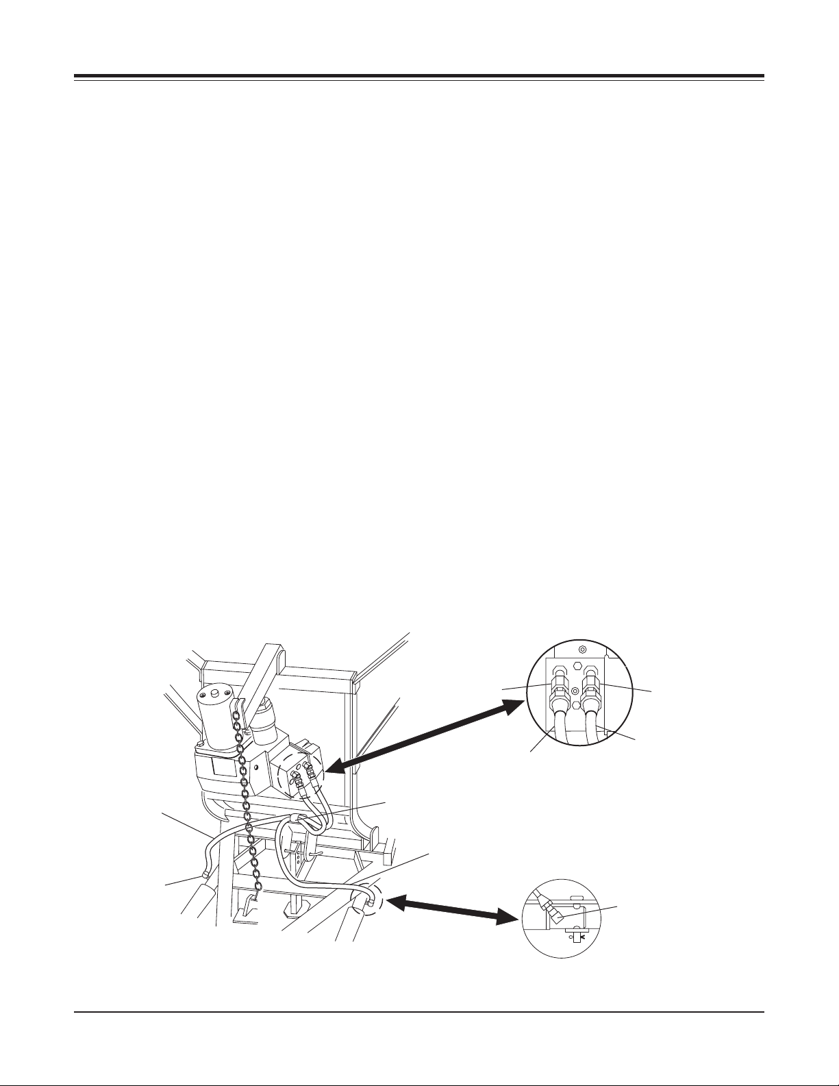
Assembling Hydraulic Fittings and Hoses
1. (Hoses and fittings are in the Hydraulics Box.)
Remove top two 1/4" pipe plugs from front face of
valve on hydraulic unit. Install two 45° swivel
fittings into pipe plug holes. Tighten fittings so the
hose connections will be straight down in line with
valve body. (See Figure 5.)
2. Install a 1/4" street elbow into the threaded port in
base end of each Hydra-Turn® ram. Tighten fittings
so they are oriented 45° from vertical towards the
blade. (See Figure 5.)
3. Install a hose into the street elbow on each HydraTurn ram. Tighten each hose.
4. Route both hoses in front of lift frame and from
passenger side to driver side through hose loop on
middle cross angle of lift frame.
5. Attach hoses to 45° swivel fitting on hydraulic unit
as follows:
• Passenger side hose to rear 45° swivel fitting.
• Driver side hose to front 45° swivel fitting.
Remove twists from both hoses and tighten swivel
connections.
Passenger Side
Hydraulic Hose
(To Rear 45
Swivel Fitting)
1/4" Street Elbow
°
DO NOT use pipe tape/sealant when connecting hoses
to swivel fittings.
Front 45
Swivel Fitting
Lift Frame Hose Loop
°
Driver
Side Hose
Driver Side Hydraulic Hose
(To Front 45° Swivel Fitting)
Figure 5
Hydraulic Fitting Orientation and Hose Routing
Rear 45
Swivel Fitting
Passenger Side Hose
1/4" Street Elbow
(Typical Orientation Each Side)
°
Form No. 63551
7
September 1,1999
Page 10
ASSEMBLY INSTRUCTIONS
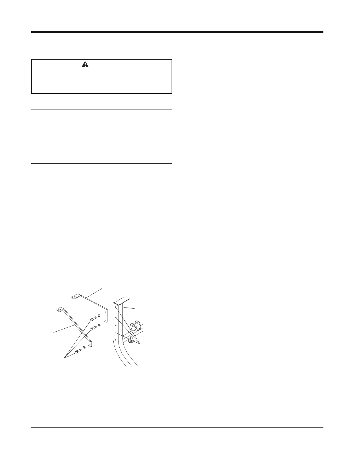
Assembling Light Brackets and Headlamps
CAUTION
Do not position or align lights so that the beam
is blocked by the raised blade
3. Assemble headlamps (found in headlamp kit) to
the light brackets, placing the headlamp swivel
above the bracket. Loosely attach with lock
washers and nuts below the brackets.
Aim headlamps when plow is attached to vehicle.
NOTE: Lights may be positioned lower than the
hole locations allow. Using the existing holes as
a guide for the top light bracket, position the
lights where preferred. Using the existing light
bracket holes as a guide, drill 3/8" diameter
holes through the lift frame and attach brackets
with provided 3/8" x 1-1/4" bolt and locknuts.
Two options for headlamp mounting height are
available through 5 holes in the lift frame side angles.
The difference in height between the two positions is
3-3/16". LSX blades normally use the top mounting
holes.
1. Align two holes of two top light brackets with the
top and second holes in lift frame side angles.
Loosely attach with two 3/8" x 1-1/4" bolts and
locknuts on each side.
2. Loosely attach the small hole end of the two
bottom light brackets to the fourth hole in each lift
frame side angle with a 3/8" x 1-1/4" bolt and
locknut on each side.
4. Tighten bolts holding light brackets to lift frame.
5. Install vinyl caps on headlamp mounting studs.
Bottom
Light
Bracket
3/8" x 1-1/4"
Bolts &
Locknuts
Form No. 63551
Top Light Bracket
Figure 6
Light Bracket Installation
Lift Frame
Side Angle
Use Top,
2nd, and
4th Holes
8
September 1,1999
Page 11
ASSEMBLY INSTRUCTIONS
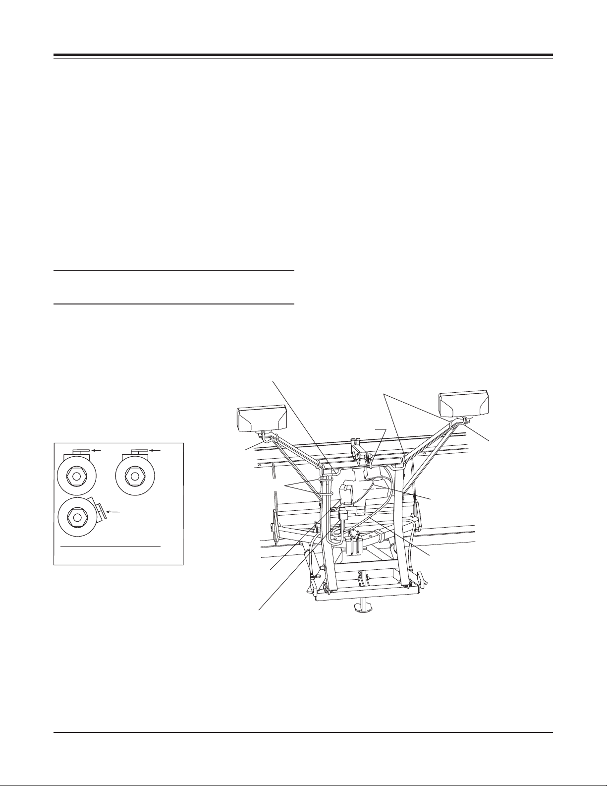
Assembling Hydraulic Unit Wiring
1. Route wiring harness from headlamps along top
light brackets and across back of lift frame to driver
side of lift frame. Use any excess harness to make
a drip loop under each headlamp. Secure harness
to each light bracket with two short cable ties, and
to top angle of lift frame with a long cable tie.
2. Remove cover from valve manifold on hydraulic
unit. Route branch of harness with loose wires to
manifold. Apply dielectric grease (P.N. 56099,
furnished in hydraulics box) into the opening of
each wire terminal before connecting to coil
terminals as shown on label inside of cover.
NOTE: Dielectric grease has been applied to coil
terminals. DO NOT wipe off terminals.
Plow Harness
(Headlamps &
Hydraulic Unit)
3. With harness strain relief inside cover at slot and
black/orange wire outside of cover, replace cover
and secure with screws.
4. While allowing slack in harness to hydraulic unit,
secure harness to inside of lift frame side rail with
two long cable ties.
Cable Tie
(Each Side)
Diagram Inside Cover
GREEN
3W COIL
4W COIL
ELECTRICAL CONNECTIONS:
Colored wires as shown.
Black wire tabs, one to each coil.
WIRE
2W COIL
BLUE
WIRE
WHITE
WIRE
Drip Loop
in Harness
Long
Cable Ties
Valve
Manifold
Cover
Cable Boot on
Boot Bracket
Long
Cable Tie
Install
Vinyl Cap
(On Headlamp
Mounting Stud)
Black/Orange Wire
(To Motor Frame)
Short Cable
Assembly
Figure 7
Form No. 63551
9
September 1,1999
Page 12
ASSEMBLY INSTRUCTIONS
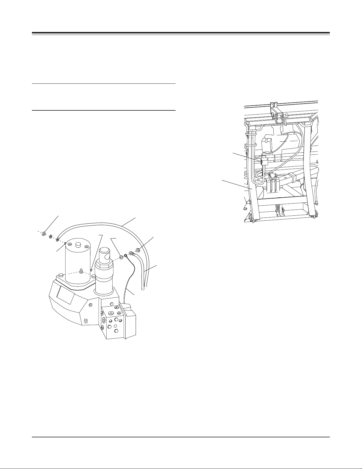
Assembling Battery Cable To Motor
Apply a light coating of dielectric grease to connectors
before assembly.
NOTE: Retain dielectric grease tube for use
during vehicle mount installation. Pass tube on
to end user.
All parts installed in this section are found in the
hydraulics box.
1. Attach black/red battery cable to motor terminal on
hydraulic unit. Secure nut to 50-60 in. lbs.
2. Attach black battery cable (without a stripe) and
the black/orange wire from under the valve
manifold cover to the ground stud. Secure nut to
50-60 in. lbs.
Motor Terminal Nut*
Black/Red
Cable
Motor
Terminal
Ground Stud
Lock
Washer
Motor
Terminal
Nut*
3. Slide small pocket of cable boot onto vertical tab of
boot bracket. Insert harness plugs into boot for
storage when plow is removed from vehicle.
Cable Boot on
Boot Bracket
Lift Frame
Figure 9
*Torque motor terminal
nuts 50-60 in. lbs.
Black
Cable
Black/Orange
Wire
Figure 8
Form No. 63551
10
September 1,1999
Page 13
ASSEMBLY INSTRUCTIONS
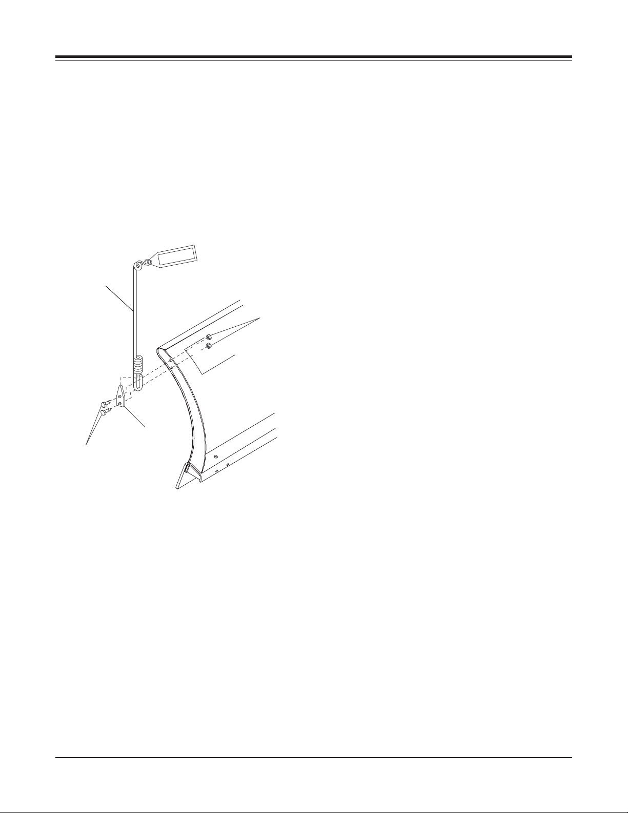
BLADE GUIDE ASSEMBLY INSTALLATION
INSTRUCTIONS
1. Attach blade guide bracket to outer rib using 5/16”
Hex Flange Screw as shown.
2. Insert pointed end of clamp into coil of the blade
guide rod. Attach a blade guide rod to each outer
rib using 5/16" x 1" cap screws and locknuts as
shown.
WESTERN
Blade Guide
Assembly
5/16" Hex
Locking Nut
5/16" Hex
Head Screw
Clamp
Figure 10
Form No. 63551
11
September 1,1999
Page 14

WESTERN PRODUCTS
P.O. BOX 245038
MILWAUKEE, WI 53224-9538
A DIVISION OF DOUGLAS DYNAMICS, L.L.C.
Western Products reserves the right under its Product Improvement Policy to change construction or design details and furnish equipment
when so altered without reference to illustrations or specifications used herein. Western Products and the vehicle manufacturer may require
and/or recommend optional equipment for snow removal. Western Products offers a limited warranty on the snowplows and accessories.
See separately printed page for this important information. The following are registered® trademarks of Douglas Dynamics, L.L.C.:
HYDRA-TURN®, UNIMOUNT®, and WESTERN®.
Printed in USA
September 1, 1999Form No. 63551
 Loading...