

Page 1

CAUTION
Read this manual before operating or servicing snowplow.
This document supersedes all editions with an earlier date.
OWNER'S MANUAL
Original Instructions
August 15, 2011
Lit. No. 49513, Rev. 00
Page 2

Lit. No. 49513, Rev. 00 3 August 15, 2011
SNOWPLOW OWNER DATA SHEET
Register your snowplow online at www.westernplows.com
Owner Name: ________________________________________________________________________
Date Purchased: ______________________________________________________________________
Dealer Name: ___________________________________________ Phone: ______________________
Dealer Address: _______________________________________________________________________
Vehicle Model/Year: ___________________________________________________________________
Snowplow Model/Year: _________________________________________________________________
Snowplow Type/Size: ___________________________________________ Weight: ___________ lb/kg
Ballast: No ___ Yes ___ Amount ____________lb/kg
FloStat
®
Hydraulic Unit Serial Number: _____________________________________________________
Blade Serial Number: __________________________________________________________________
Page 3

Page 4

Lit. No. 49513, Rev. 00 5 August 15, 2011
TABLE OF CONTENTS
Snowplow Owner Data Sheet ...............................3
Preface ..................................................................7
Safety ....................................................................8
Vehicle Application Information ...........................15
Ballast Requirements .......................................16
Getting To Know Your Snowplow ........................17
UltraMount
®
Snowplow ....................................17
Blades ..............................................................18
Straight Blades..............................................19
HTS™ Blades ...............................................19
MIDWEIGHT™ Blades .................................19
PRO-PLOW® Series 2 Blades ......................19
PRO PLUS® Blades ......................................20
MVP PLUS™ Blades ....................................20
WIDE-OUT™ Blades ....................................20
A-Frame/T-Frame, Quadrant & Lift Frame .......21
Straight & WIDE-OUT Blades .......................21
MVP PLUS Blades ........................................21
Weights ........................................................... 22
NIGHTHAWK™ Snowplow Headlamps ...........23
Vehicle Mount...................................................23
FloStat® Hydraulic System ...............................24
System Capacity ...........................................26
Pump Motor Specifi cations (All Blades) ........26
Cab Controls ....................................................27
Straight Blade Controls .................................28
MVP PLUS & WIDE-OUT Blade Controls ... 29
Accessories and Options ................................... 30
Mounting Snowplow To Vehicle ...........................31
Operating Your Snowplow .................................. 33
Cab Controls ................................................... 33
Straight Blade Hand-Held Control ............... 33
Straight Blade Joystick Control .................... 36
MVP PLUS & WIDE-OUT Blades
Hand-Held Control ..................................... 40
Joystick Control .......................................... 44
FLEET FLEX Electrical System ....................49
SECURITY GUARD™ System ................. 50
Smooth Stop ............................................. 54
One-Touch FLOAT .................................... 55
MVP PLUS Blade Positions ............................ 56
WIDE-OUT Blade Positions ............................ 59
Snowplow Headlamp Check ............................62
Disc Shoe Adjustment ..................................... 63
Hydraulic System ............................................ 65
Blade Drop Speed Adjustment ........................ 66
Transporting Snowplow ................................... 68
Driving and Plowing on Snow and Ice ................ 69
Page 5

Lit. No. 49513, Rev. 00 6 August 15, 2011
Plowing Snow ......................................................70
General Instructions .........................................71
Hard Packed Snow .......................................72
Deep Snow ...................................................72
Clearing Driveways .......................................73
Clearing Parking Lots ...................................73
Parking with Snowplow Attached .....................74
Towing Disabled or Stuck Vehicle ....................74
Removing Snowplow from Vehicle & Storage .....75
Maintenance ........................................................79
Aiming Headlamp Beams.................................79
Straight Blade Hydraulic Unit Cover—
Remove and Replace .....................................81
Preseason Check ............................................ 83
Postseason Maintenance ................................ 84
Maintenance and Adjustment .......................... 85
MVP PLUS™ Cutting Edge Wear and
Leveling Adjustment Procedure ......................87
Hydraulic System ............................................ 89
Fluid Level .................................................... 89
Annual Fluid Change ....................................91
Air Removal – HTS™/Straight Blades ...... 95
Air Removal – MVP PLUS Blades ............ 96
Air Removal – WIDE-OUT™ Blades .........97
Hose or Fitting Replacement ....................... 98
Procedure for Installing Hydraulic
Fittings and Hoses ..................................... 98
Fuse Replacement .........................................100
Vehicle ............................................................100
Recycle ..........................................................101
Blade Finish ...................................................101
Emergency Parts/Tools ..................................101
Troubleshooting ..............................................102
Harness Diagram – 3-Port, 2-Plug System .......103
Most of the information in this Owner's Manual
applies to all UltraMount
®
applications.
Differences between MVP PLUS and WIDE-OUT
applications are called out in the text, or under
separate headings, as required. Pages that apply
only to one or the other are called out as
or on the outside corner of the page
heading.
TABLE OF CONTENTS
Page 6

Lit. No. 49513, Rev. 00 7 August 15, 2011
PREFACE
PREFACE
Welcome to the growing family of WESTERN®
snowplow owners.
This manual provides safety, operation and
maintenance information for your new WESTERN
snowplow. To keep your snowplow in good
condition, read and understand this manual and
follow its recommendations. Failure to do so may
affect your warranty coverage.
When service is necessary, your local WESTERN
outlet knows your snowplow best. Contact your
snowplow outlet for maintenance, service or
any other assistance you may require. We have
enclosed a "Report Card" in your Owner's Manual
packet for your use.
Your WESTERN snowplow FloStat
®
hydraulic unit
has a serial number. Record this serial number on
the Snowplow Owner Data Sheet at the front of
this manual.
Before using your WESTERN snowplow, make
sure your vehicle is equipped with all the vehicle
manufacturer's and our required options for
plowing.
FACTORY ORIGINAL PRODUCTS
Your WESTERN snowplow is a valuable
investment. The best way to assure original
equipment reliability and effi ciency is to purchase
only genuine Factory Original parts and
accessories. "Will-fi t" parts and accessories can
alter your snowplow's performance characteristics
and may affect your product warranty.
Protect your investment by staying with the best—
original WESTERN parts and accessories from
your local WESTERN outlet.
Page 7

Lit. No. 49513, Rev. 00 8 August 15, 2011
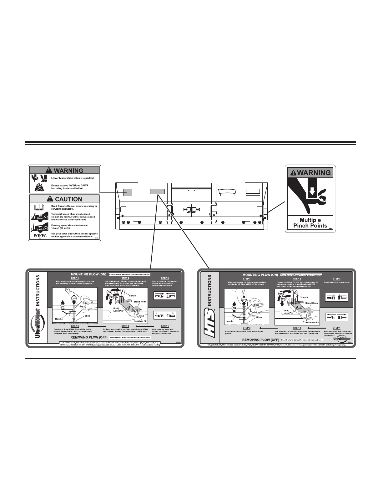
SAFETY
WARNING/CAUTION & INSTRUCTION
LABELS
Become familiar with and inform users about the
warning/caution, serial number and instruction
labels on the back of the blade.
NOTE: If labels are missing or cannot be read,
see your sales outlet.
SAFETY DEFINITIONS
NOTE: Indicates a situation or action that can
lead to damage to your snowplow and vehicle
or other property. Other useful information
can also be described.
WARNING
Indicates a potentially hazardous
situation, that if not avoided, could result
in death or serious personal injury.
CAUTION
Indicates a potentially hazardous situation
that, if not avoided, may result in minor
or moderate injury. It may also be used to
alert against unsafe practices.
Page 8
Lit. No. 49513, Rev. 00 9 August 15, 2011
SAFETY
Warning/Caution Label
Instruction Label
WIDE-OUT™ Blades Only
(both sides)
Multiple Pinch Points Label
OR
Page 9
Lit. No. 49513, Rev. 00 10 August 15, 2011
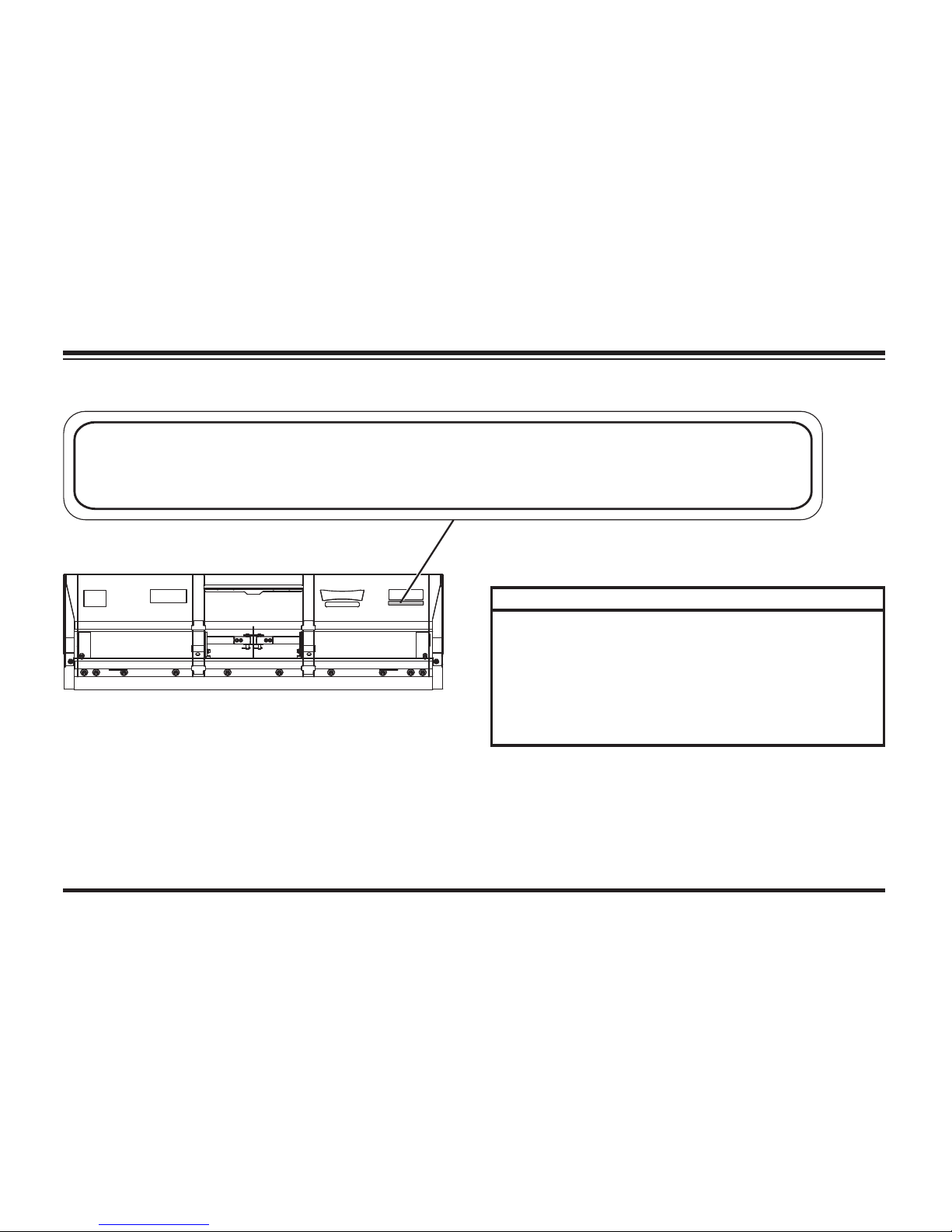
SAFETY
Code Defi nition
YY 2-Digit Year
MM 2-Digit Month
DD 2-Digit Day
LL 2-Digit Location Code
XXXX 4-Digit Sequential Number
ZZZZZ 5-Digit Blade Assembly PN
YYMMDDLLXXXXZZZZZ
ZZZZZ
zzzzz
YYMMDDLLXXXXZZZZZ
Serial Number Label
Page 10
Lit. No. 49513, Rev. 00 11 August 15, 2011
SAFETY
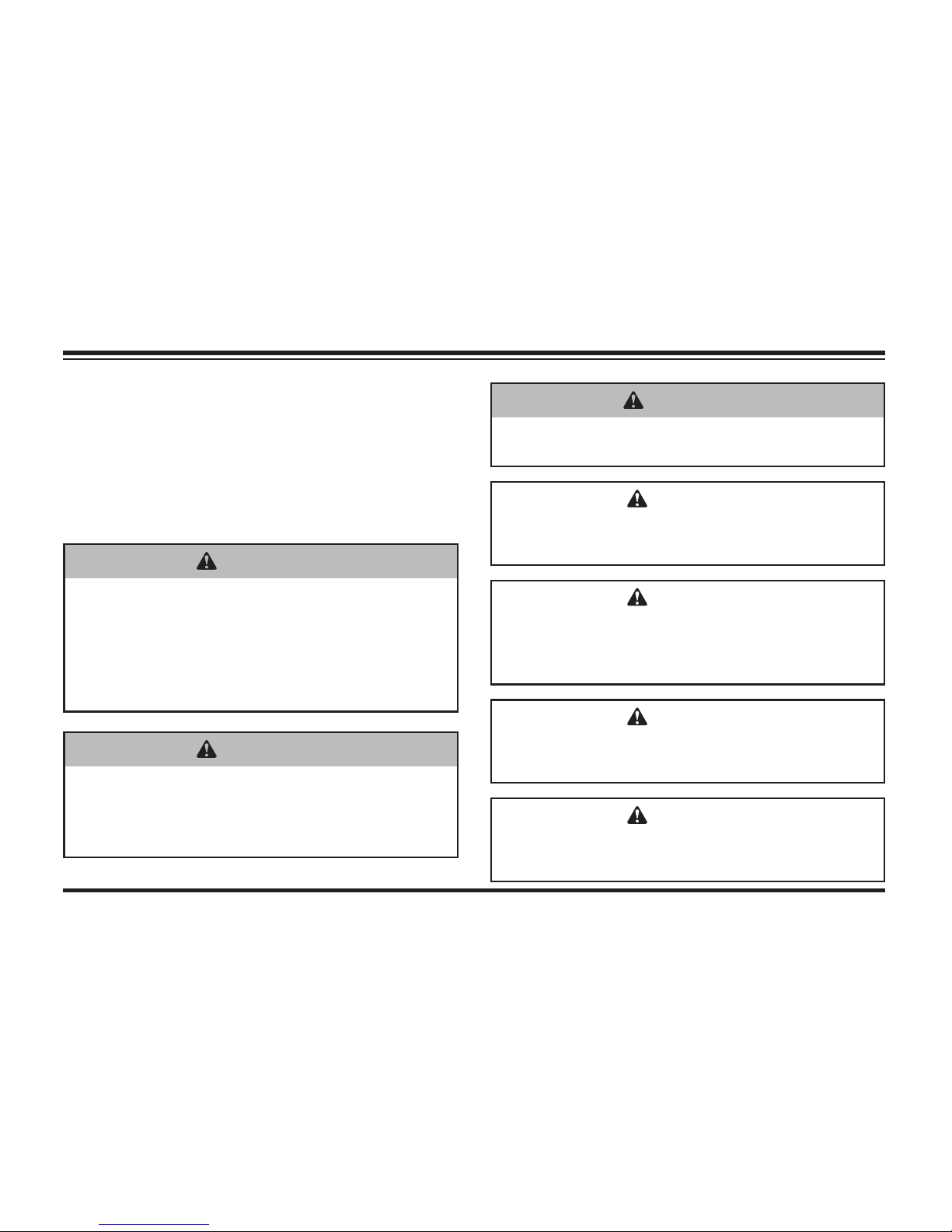
SAFETY PRECAUTIONS
Improper installation and operation could cause
personal injury, and/or equipment and property
damage. Read and understand labels and the
Owner's Manual before installing, operating or
making adjustments.
WARNING
Lower blade when vehicle is parked.
Temperature changes could change
hydraulic pressure, causing the blade to
drop unexpectedly or damaging hydraulic
components. Failure to do this could
result in serious personal injury.
WARNING
Remove blade assembly before placing
vehicle on hoist.
CAUTION
Read Owner's Manual before operating or
servicing snowplow.
WARNING
Do not exceed GVWR or GAWR including
the blade and ballast. The rating label
is found on the driver-side vehicle door
cornerpost.
CAUTION
Plowing speed should not exceed 10 mph
(16 km/h).
CAUTION
See your WESTERN® outlet for application
recommendations.
CAUTION
Transport speed should not exceed
45 mph (72 km/h). Further reduce speed
under adverse travel conditions.
Page 11

Lit. No. 49513, Rev. 00 12 August 15, 2011
SAFETY
HYDRAULIC SAFETY
• Always inspect hydraulic components and
hoses before using. Replace any damaged or
worn parts immediately.
• If you suspect a hose leak, DO NOT use your
hand to locate it. Use a piece of cardboard or
wood.
WARNING
Hydraulic fl uid under pressure can cause
skin injection injury. If you are injured
by hydraulic fl uid, get medical attention
immediately.
FUSES
The WESTERN® electrical and hydraulic systems
contain several automotive blade-style fuses. If
a problem should occur and fuse replacement
is necessary, the replacement fuse must be
of the same type and amperage rating as the
original. Installing a fuse with a higher rating can
damage the system and could start a fi re. Fuse
Replacement, including fuse ratings and locations,
is located in the Maintenance section of this
Owner's Manual.
Page 12

Lit. No. 49513, Rev. 00 13 August 15, 2011
SAFETY
PERSONAL SAFETY
• Remove ignition key and put the vehicle in
park or in gear to prevent others from starting
the vehicle during installation or service.
• Wear only snug-fi tting clothing while working
on your vehicle or snowplow.
• Do not wear jewelry or a necktie, and secure
long hair.
• Wear safety goggles to protect your eyes from
battery acid, gasoline, dirt and dust.
• Avoid touching hot surfaces such as the
engine, radiator, hoses and exhaust pipes.
• Always have a fi re extinguisher rated BC
handy, for fl ammable liquids and electrical
fi res.
FIRE AND EXPLOSION
Be careful when using gasoline. Do not use
gasoline to clean parts. Store only in approved
containers away from sources of heat or fl ame.
CELL PHONES
A driver's fi rst responsibility is the safe operation
of the vehicle. The most important thing you can
do to prevent a crash is to avoid distractions and
pay attention to the road. Wait until it is safe to
operate Mobile Communication Equipment such
as cell phones or two-way radios.
WARNING
Gasoline is highly fl ammable and gasoline
vapor is explosive. Never smoke while
working on vehicle. Keep all open fl ames
away from gasoline tank and lines. Wipe
up any spilled gasoline immediately.
Page 13

Lit. No. 49513, Rev. 00 14 August 15, 2011
SAFETY
VENTI L ATI ON BATTERY SAFET Y
NOISE
Airborne noise emission during use is below
70 dB(A) for the snowplow operator.
CAUTION
Batteries normally produce explosive
gases, which can cause personal injury.
Therefore, do not allow fl ames, sparks or
lit tobacco to come near the battery. When
charging or working near a battery, always
cover your face and protect your eyes,
and also provide ventilation.
• Batteries contain sulfuric acid, which
burns skin, eyes and clothing.
• Disconnect the battery before removing
or replacing any electrical components.
WARNING
Vehicle exhaust contains lethal fumes.
Breathing these fumes, even in low
concentrations, can cause death. Never
operate a vehicle in an enclosed area
without venting exhaust to the outside.
Page 14

Lit. No. 49513, Rev. 00 15 August 15, 2011
Vehicle application recommendations are based
on the following:
• The vehicle with the snowplow installed must
comply with applicable Federal Motor Vehicle
Safety Standards (FMVSS).
• The vehicle with the snowplow installed
must comply with the vehicle manufacturer's
stated gross vehicle and axle weight ratings
(found on the driver-side door cornerpost
of the vehicle) and the front and rear weight
distribution ratio. In some cases, rear ballast
may be required to comply with these
requirements. See "Ballast Requirements" in
this section.
VEHICLE APPLICATION INFORMATION
CAUTION
See your WESTERN® outlet/Web
site for specifi c vehicle application
recommendations before installation. The
Selection List has specifi c vehicle and
snowplow requirements.
• WESTERN Selection List/Quick Match is
based on available vehicle capacity for
snowplow equipment on a representative
vehicle equipped with options commonly
used for plowing and with 300 lb of front seat
occupant weight.
• Weights of front seat occupants can be adjusted
above 300 lb but vehicle with snowplow must
not exceed vehicle GVWR or GAWR.
• In some cases there may be additional
limitations and requirements.
• Installation, modifi cation and addition of
accessories must comply with published
WESTERN recommendations and instructions.
Available capacity decreases as the vehicle is
loaded with cargo or other truck equipment, or
snowplow accessories are installed.
• If there is uncertainty as to whether available
capacity exists, the actual vehicle as
confi gured must be weighed.
Page 15

Lit. No. 49513, Rev. 00 16 August 15, 2011
VEHICLE APPLICATION INFORMATION
BALLAST REQUIREMENTS
Ballast (additional weight) is an important part of
qualifying vehicles for snowplow eligibility. Rear
ballast must be used when necessary to remain
in compliance with axle ratings and ratios as
specifi ed by the vehicle manufacturer.
If ballast is required, it is important that it be
secured properly behind the rear axle. A ballast
retainer kit is available from your WESTERN
®
outlet (PN 62849).
NOTE: The ballast retainer kit is for snowplow
vehicles requiring ballast. See your WESTERN
outlet for the correct amount of ballast
required. Include the weight of the retainer as
part of the ballast requirement. Sand bags are
recommended for use as ballast.
Position
and secure ballast
as close to the tailgate
as possible.
NOTE: Ballast recommended and its weight
calculations assume the entire width of the
bed is fi lled as close to tailgate as possible.
Page 16
Lit. No. 49513, Rev. 00 17 August 15, 2011
GETTING TO KNOW YOUR SNOWPLOW
UltraMount® SNOWPLOW
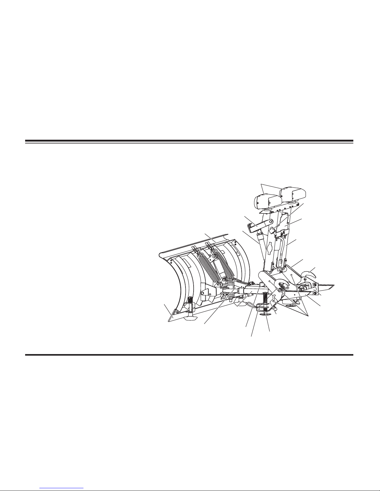
The UltraMount snowplow consists of all the components
that are readily removable from the vehicle as a unit.
This includes the blade, quadrant, lift frame, A-frame/
T-frame, hydraulic unit and the NIGHTHAWK™ snowplow
headlamps. The snowplow is ready and easy to mount
when you need to plow snow. When plowing is completed,
remove the snowplow.
UltraMount snowplows have through holes in
the lower lift frame and stand leg. The
holes will accept 1/2" trailer hitch pin
locks, which are available at most auto
supply or trailer equipment stores.
These holes, used with locks, may be
used to secure the snowplow assembly
on or off the truck to deter theft.
The snowplow shall be installed according
to instructions supplied. WESTERN
®
outlets
are trained to provide this service and other
services for this snowplow.
Headlamps
FloStat
®
Hydraulic Unit
Upper Lift Frame
Cable Boot
Lower Lift Frame
Stand Shoe
Plow Horn
Angling
Ram
Blade
Lift Ram
Lift Arm
Cutting
Edge
Quadrant
Stand Hook
Pivot Bar
Stand
A-Frame
Lock Pin Holes
Stand
Lock Pin
Actual
confi guration
varies by
model
Page 17

Lit. No. 49513, Rev. 00 18 August 15, 2011
GETTING TO KNOW YOUR SNOWPLOW
There is no need to unhook the chains or the
hydraulic hoses. When the lift frame is pinned to
the stands and locked in place (see blade label
or snowplow removal section of this manual), the
complete UltraMount
®
snowplow can easily be
moved around on most hard surfaces.
BLADES
WESTERN® snowplows with steel blades are
constructed of heavy gauge steel. To increase
rigidity and strength, the blades are reinforced with
several vertical ribs. The top edges are formed for
added strength and improved appearance.
WESTERN snowplows with poly blades are
constructed of a high molecular weight polyethylene
sheet that is supported with structural steel.
WESTERN blades have replaceable high-carbon
steel cutting edges bolted to the bottom. Straight
blade and WIDE-OUT™ cutting edges should
be replaced when worn to the bottom edge of
the blade. MVP PLUS™ cutting edges should
be replaced when they are worn within 1" of the
carriage bolts. (See Maintenance section in this
manual.)
Your new blade's steel components are protected
with a baked-on ULTRAFINISH™ powder coat
over a base primer coat that resists cracking,
Page 18

Lit. No. 49513, Rev. 00 19 August 15, 2011
GETTING TO KNOW YOUR SNOWPLOW
corrosion, scratching and rust. This coating—
many times thicker than paint—will maintain its
luster and glossy good looks. It can be touched up
when necessary.
Blade guides are included with your complete
snowplow. These help the operator to visualize the
edges of the blade and aid in blade positioning.
Straight Blades
WESTERN® straight blades with their exclusive
Roll-Action™ design roll snow ahead and to the
side instead of just pushing snow. This action
means you can move more snow and move it faster
using less power, saving fuel and reducing wear
and tear on both the vehicle and the snowplow.
Large, adjustable disc-type skid shoes are
standard on some models. These rotate 360°
for longer wear and better blade fl otation over
all surfaces. For severe service, heavy-duty disc
shoes are standard on all PRO-PLOW® Series 2
and PRO PLUS® snowplows.
HTS™ Blades
HTS, the half-ton snowplow. The HTS blade
is a full-size, full-featured snowplow designed
exclusively for half-ton pickup trucks. It handles
light commercial, institutional and extendeduse homeowner applications, providing rugged,
pro-like performance without the extra weight.
Available in 7-1/2' mild steel.
MIDWEIGHT™ Blades
The 7-1/2' MIDWEIGHT snowplow is a highperformance snowplow designed for personal
and light commercial use. The MIDWEIGHT blade
is available in ULTRAFINISH™ powder-coated
steel or high-density polyethylene. The poly
option offers exceptional snow-rolling action and a
maintenance-free surface.
PRO-PLOW Series 2 Blades
Leave it to the pros. Designed to meet the
requirements of the professional snow plower, the
Page 19

Lit. No. 49513, Rev. 00 20 August 15, 2011
7-1/2' and 8' PRO-PLOW® Series 2 models are
available in both ULTRAFINISH™ powder-coated
steel and poly. The 8-1/2' model is offered in steel
only.
PRO PLUS® Blades
Big, tough and built to last. Contractors continue
to be impressed with the strength, durability and
versatility of the PRO PLUS blade. Designed
for heavy-duty commercial and light municipal
applications, the 8', 8-1/2' and 9' PRO PLUS
line fi ts a wide range of vehicles, from 3/4-ton to
F-550-size trucks.
MVP PLUS™ Blades
Each of the MVP PLUS blade wings has a trip
edge. Heavy-duty compression springs hold
each trip edge in the plowing position (2 springs
per blade wing for 7-1/2' and 8-1/2', 3 for 9-1/2').
The springs are a safety device which allow the
trip edge to rotate back and ride over obstacles
such as low curbs, manhole covers, etc., without
damaging the snowplow, vehicle, or injuring
the driver. The trip springs need no adjustment
and offer protection in all blade wing positions.
Available accessories include a rubber defl ector,
bolt-on disc shoes, blade wing extensions, blade
stops and a back drag edge.
WIDE-OUT™ Blades
The WESTERN® WIDE-OUT snowplow provides
you the ability to extend the width of your blade
hydraulically, allowing you to carry up to 40% more
snow for increased plowing effi ciency. Positions
include a retracted 8' width, 10' expanded width and
a scoop width of nearly 9'. The WIDE-OUT blade
can fully angle in the scoop position, increasing
the snow-carrying capacity while effectively
maneuvering around obstacles or turning corners.
Its dual power bar design and six vertical ribs
provide exceptional strength, while the durable
polyurethane cutting edge on each wing reduces
wear and helps protect the blade while tripping.
Available accessories include a rubber snow
defl ector, bolt-on shoe kit and a back drag edge.
GETTING TO KNOW YOUR SNOWPLOW
Page 20

Lit. No. 49513, Rev. 00 21 August 15, 2011
GETTING TO KNOW YOUR SNOWPLOW
A-FRAME/T-FRAME, QUADRANT AND
LIFT FRAME
Straight and WIDE-OUT™ Blades
The quadrant is attached to the back of the blade
with heavy-duty trip springs and either bolts
with locknuts or clevis pins with cotters. The
trip springs allow the blade to trip forward and
ride over obstacles such as low curbs, manhole
covers, etc., without damaging the blade or the
vehicle, or injuring the driver. See the Maintenance
section for Trip Spring Adjustment.
The quadrant is attached to the triangular A-frame
with a pivot bolt. The pivot bolt allows the quadrant
and blade to swing right or left.
The hydraulic unit is mounted on the front of
the lift frame. The hoses remain connected to
the hydraulic unit and the rams. The snowplow
headlamps are also attached to the lift frame.
MVP PLUS™ Blades
The wings are attached to the T-frame with a
hinge pin, which allows the wings to extend and
retract.
The hydraulic unit is mounted on the front of
the lift frame. The hoses remain connected to
the hydraulic unit and the rams. The snowplow
headlamps are also attached to the lift frame.
Page 21
Lit. No. 49513, Rev. 00 22 August 15, 2011
GETTING TO KNOW YOUR SNOWPLOW
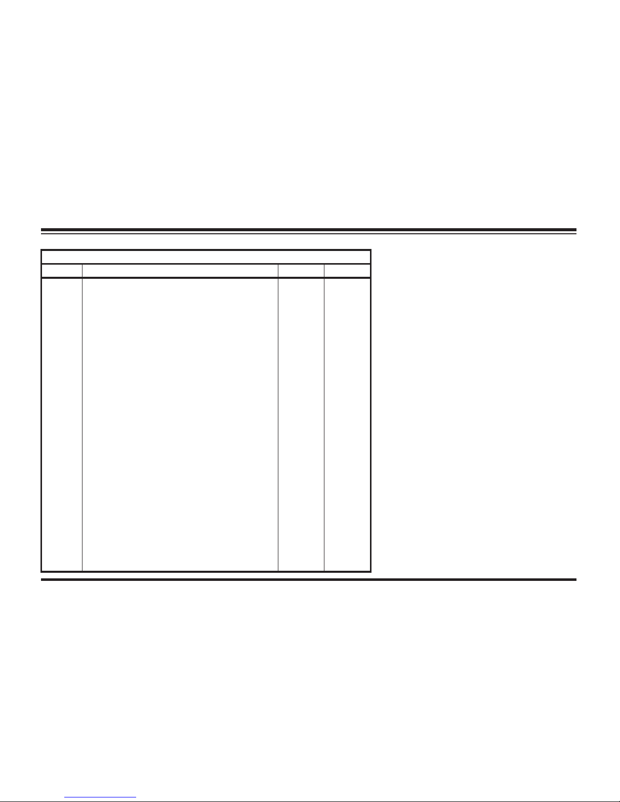
Snowplow Weights
Size Blade Assembly Wt (lb) Wt (kg)
7-1/2' HTS™ Snowplow 412 187
7-1/2' MIDWEIGHT™ Snowplow 540 245
7-1/2' MIDWEIGHT Snowplow (Poly) 532 241
7-1/2' PRO - PLOW
®
Series 2 Snowplow 653 296
7-1/2' POLY PRO-PLOW® Series 2 Snowplow 677 307
8' PRO-PLOW Series 2 Snowplow 668 303
8' POLY PRO-PLOW Series 2 Snowplow 690 313
8-1/2' PRO-PLOW Series 2 Snowplow 686 311
7-1/2' PRO PLUS® Snowplow 789 358
8' PRO PLUS Snowplow 805 365
8-1/2' PRO PLUS Snowplow 821 372
9' PRO PLUS Snowplow 837 380
7-1/2' MVP PLUS™ Snowplow 827 375
7-1/2' MVP PLUS Snowplow (Poly) 799 362
8-1/2' MVP PLUS Snowplow 880 399
8-1/2' MVP PLUS Snowplow (Poly) 847 384
9-1/2' MVP PLUS Snowplow 988 448
9-1/2' MVP PLUS Snowplow (Poly) 946 429
8'–10' WIDE-OUT™ Snowplow 940 426
9' UniMount® HEAVYWEIGHT Snowplow 1048 475
10' UniMount HEAVYWEIGHT Snowplow 1106 502
Page 22

Lit. No. 49513, Rev. 00 23 August 15, 2011
NIGHTHAWK™ SNOWPLOW
HEADLAMPS
The NIGHTHAWK snowplow headlamps include a
set of rectangular, dual-beam, halogen headlamps
plus combination park and turn signals. A prewired
harness with a plug-in module requires no
headlamp wire splicing. The headlamps conform to
Federal Motor Vehicle Safety Standards (FMVSS).
When the electrical plugs are connected, the
vehicle headlamps will automatically switch to the
snowplow headlamps when they are turned ON.
When the electrical plugs are disconnected, the
headlamps will automatically switch to vehicle
headlamps when they are turned ON.
Replacement parts are available through your
local WESTERN® outlet.
GETTING TO KNOW YOUR SNOWPLOW
WARNING
Your vehicle must be equipped with
snowplow headlamps and directional
lights.
VEHICLE MOUNT
Western Products has designed custom mounts
for most vehicles. Due to differences between
vehicle models, mounts are generally not
interchangeable.
The mount is fastened to the underside of the
vehicle frame and provides the primary connecting
point between the snowplow and the vehicle.
Page 23
Lit. No. 49513, Rev. 00 24 August 15, 2011
FloStat® HYDRAULIC SYSTEM
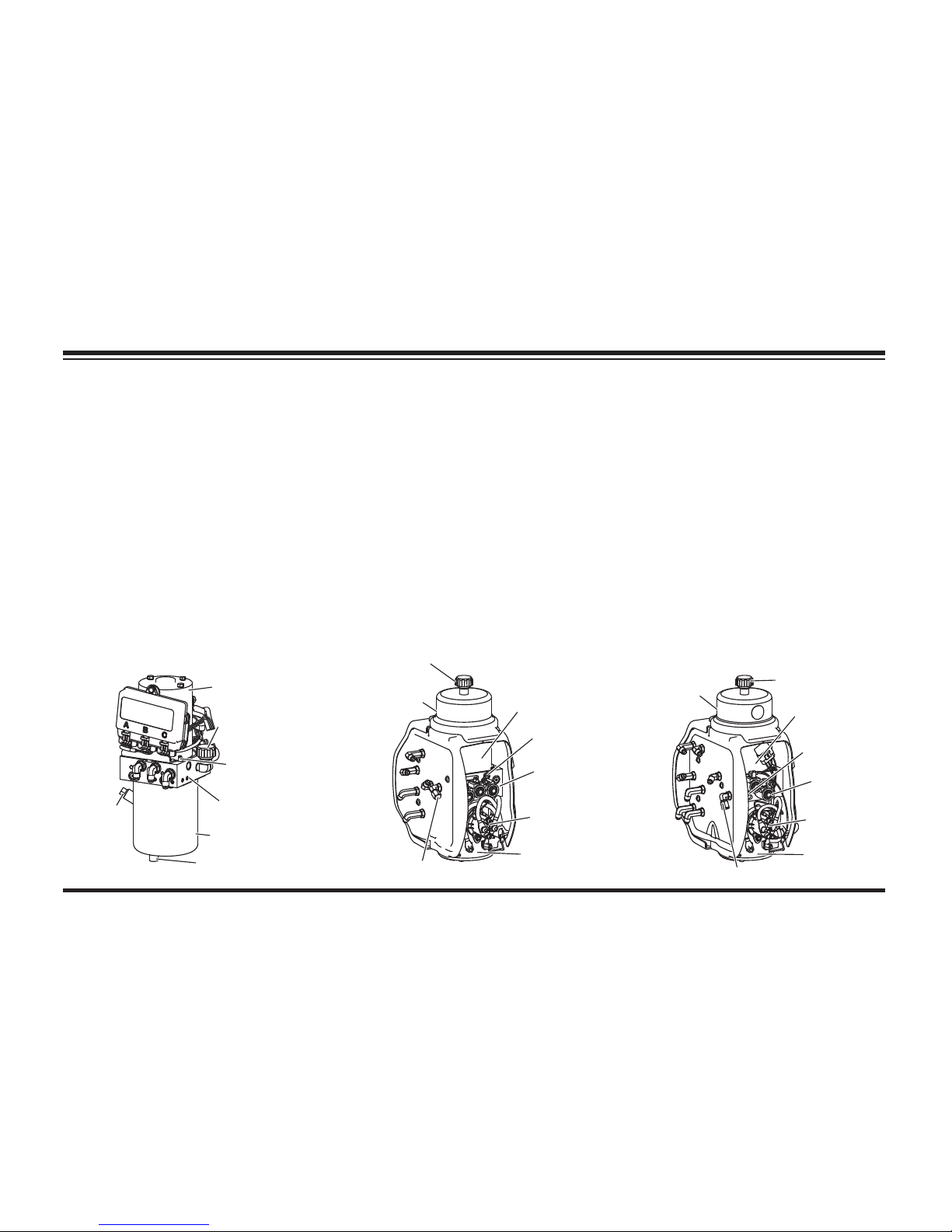
The FloStat hydraulic unit delivers fast and
uniform speed for lifting and angling.
The HTS™ hydraulic unit has blade scrape
lock circuitry built into it. This feature resists
the tendency a snowplow has to "fl oat up" as
larger amounts of snow build up in front of it
while plowing deep snow, or stacking snow into
piles. This feature is activated when the blade
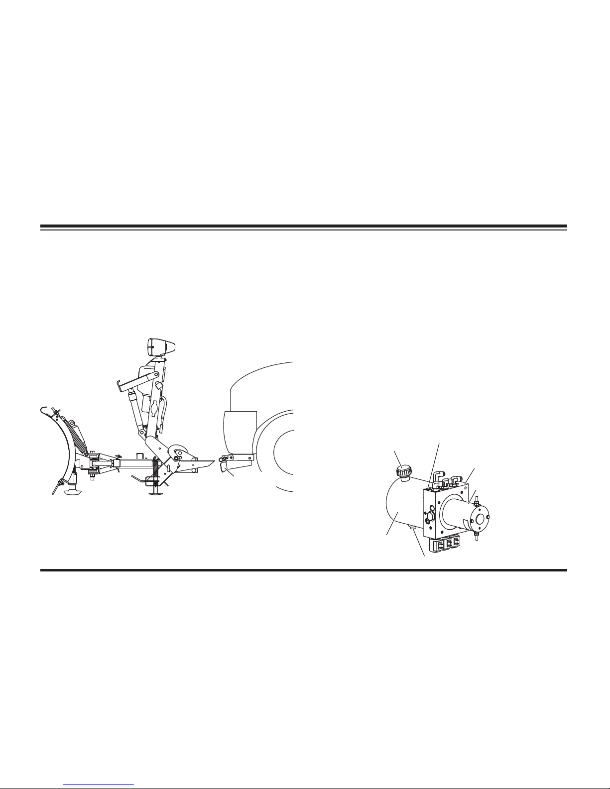
Attached to the mount are two removable receiver
brackets. The receiver brackets are attached to
the mount using pins and hairpin cotters. The
receiver brackets are easily removed to provide
even more road clearance during the non-plowing
months of the year.
GETTING TO KNOW YOUR SNOWPLOW
Receiver
Bracket
HTS™ Blades
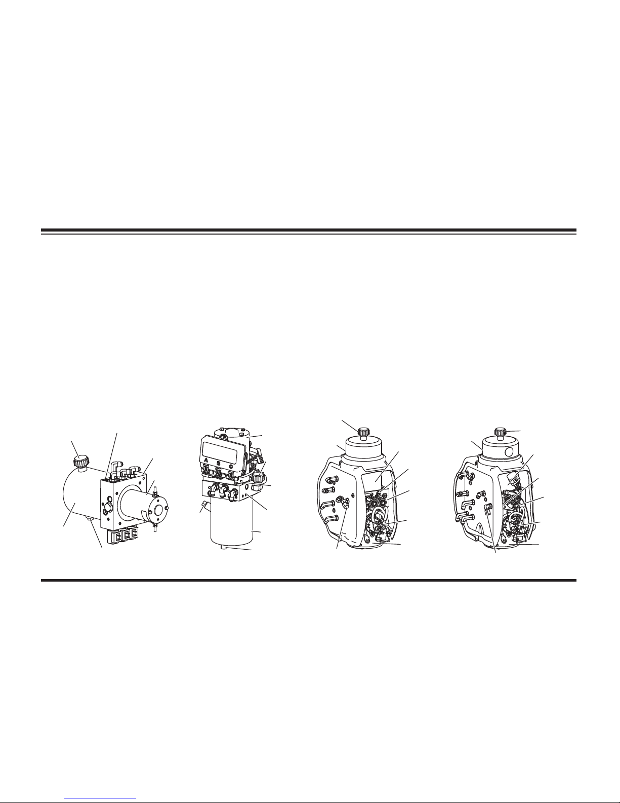
Reservoir
Moto
r
Drain Plug
Valve
Manifold
Quill
Breather/
Fill Plug
Page 24
Lit. No. 49513, Rev. 00 25 August 15, 2011
Straight Blades
Fill
Plug
Drain Plug
Reservoir
Valve
Manifold
Breathe
r
Quill
Motor
GETTING TO KNOW YOUR SNOWPLOW
The WIDE-OUT™ blade is both raised and
angled side to side in approximately 2 seconds.
Each wing individually extends and retracts in
approximately 2 seconds. Both wings together
extend in approximately 4 seconds and retract in
approximately 3 seconds.
For hydraulic fl uid type and fi lling instructions, see
"Annual Fluid Change" under "Hydraulic System"
in the Maintenance section of this manual.
MVP PLUS™ Blades
Breather
Quill
Reservoir
Valve
Manifold
Motor
Drain Cap
Fill
Plug
Motor
Relay
Breather
Fill
Plug
Quill
Valve
Manifold
Motor
Relay
Reservoir
Motor
WIDE-OUT™ Blades
Drain Cap
is in FLOAT, and is factory set. See your sales
outlet for adjustment. The HTS blade is raised in
approximately 4 seconds and angled side to side
in approximately 3 seconds.
Straight blades are raised in approximately
2 seconds and angled side to side in
approximately 4 seconds.
The MVP PLUS™ blade is both raised and angled
side to side in approximately 2 seconds.
Page 25

Lit. No. 49513, Rev. 00 26 August 15, 2011
GETTING TO KNOW YOUR SNOWPLOW
MVP PLUS™ Blades
12-volt DC with +/– Connection
2200 –2300 psi Pump Relief Valve
4550–4650 psi Plowing Relief Valve
3650–3750 psi Back Dragging Relief Valve
4.5" dia 1.5 kW Motor
0.000652 gal/rev Pump
Hydraulic Hose 1/4 SAE 100R1 and 3/8 SAE 100R17
WIDE-OUT™ Blades
12-volt DC with +/– Connection
2200 –2300 psi Pump Relief Valve
4000 psi Plowing Relief Valve
1500 & 1700 psi Wing Plowing Relief Valves
4.5" dia 1.5 kW Motor
0.000652 gal/rev Pump
Hydraulic Hose 1/4 SAE 100R1 and 3/8 SAE 100R17
System Capacity
• FloStat® Unit Reservoir ..............1-3/4 quarts
• FloStat System Total .....2-3/8 to 2-3/4 quarts
Pump Motor Specifi cations
HTS™ Blades
12-volt DC with +/– Connection
1600–1700 psi Pump Relief Valve
4000 psi Angling Relief Valve
3" dia 0.8 kW Motor
0.000477 gal/rev Pump
Hydraulic Hose SAE 100R1
Straight Blades
12-volt DC with +/– Connection
1700–1800 psi Pump Relief Valve
4000 psi Angling Relief Valve
4.5" dia 1.5 kW Motor
0.000477 gal/rev Pump
Hydraulic Hose 1/4 SAE 100R1 and 3/8 SAE 100R17
Page 26

Lit. No. 49513, Rev. 00 27 August 15, 2011
GETTING TO KNOW YOUR SNOWPLOW
CAB CONTROLS
WESTERN® snowplows come equipped with
one of two special controls: the CabCommand
hand-held control or a joystick-style control.
The MVP PLUS™ controls allow you to go from
a V-plow, to a scoop, to a standard straight-blade
snowplow, all at the touch of a button or singlelever movement.
The WIDE-OUT™ controls allow you to go from a
retracted position to a scoop position, in addition
to all the standard straight-blade positions, at the
touch of a button.
Each control has its own ON/OFF switch with an
indicator light to show when the control is powered
up. Your vehicle ignition (key) switch controls a
fused circuit that powers your cab control directly
from the battery.
The ON/OFF switch on the cab control allows
you to turn OFF the control and prevent blade
movement even when the ignition switch is ON.
The control ON/OFF switch serves as an
emergency stop if required.
All controls are protected by a replaceable fuse
located in the under hood snowplow electrical
system. See "Fuse Replacement" in the
Maintenance section of this Owner's Manual.
WARNING
To prevent accidental movement of
the blade, always turn the control OFF
whenever the snowplow is not in use. The
power indicator light will turn OFF.
Page 27
Lit. No. 49513, Rev. 00 28 August 15, 2011
GETTING TO KNOW YOUR SNOWPLOW
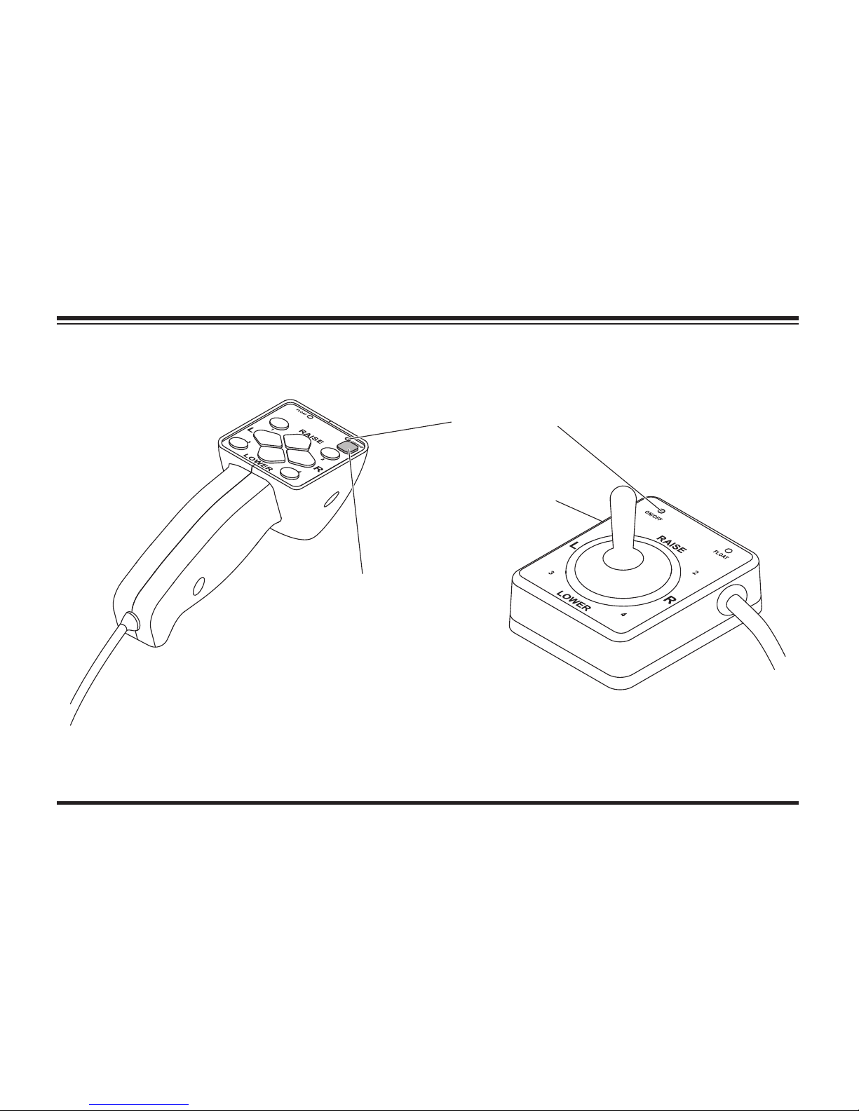
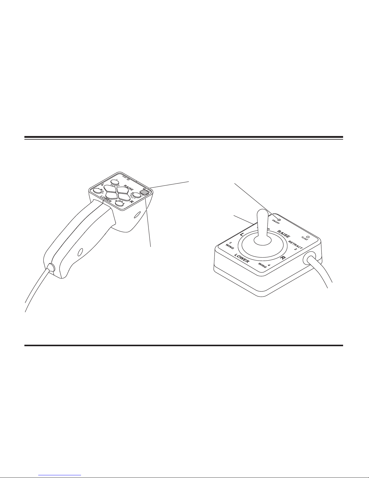
Straight Blade Controls with FLEET FLEX System
Power Indicator
Light (red)
ON/OFF Button
(Emergency Stop)
ON/OFF Switch
(Emergency Stop)
Straight Blade
Hand-Held Control
Straight Blade
Joystick Control
Page 28
Lit. No. 49513, Rev. 00 29 August 15, 2011
GETTING TO KNOW YOUR SNOWPLOW
MVP PLUS™ & WIDE-OUT™ Blade Controls with FLEET FLEX System
Power Indicator
Light (red)
ON/OFF Button
(Emergency Stop)
ON/OFF Switch
(Emergency Stop)
MVP PLUS & WIDE-OUT
Hand-Held Control
MVP PLUS & WIDE-OUT
Joystick Control
Page 29

Lit. No. 49513, Rev. 00 30 August 15, 2011
ACCESSORIES AND OPTIONS
SNOW DEFLECTOR
The optional snow defl ector, available in poly
(straight blades only) or reinforced rubber, helps
keep snow off the windshield and away from the
radiator. The defl ector improves the Roll-Action™
feature and increases snowplow effi ciency.
STRAIGHT BLADE RUBBER
CUTTING EDGE
The rubber cutting edge is available for certain
straight blade models only. It is made of resilient
rubber compounds that allow for a longer lasting
cutting edge. It adjusts easily to road surface
irregularities without gouging and removes all
types of snow, quickly and cleanly.
CURB GUARD KIT
Designed to fi t on the ends of the cutting edges,
these guards protect against scraping the bottom
edge of the blade against curbs and sidewalks.
The kit is available for straight blades and all
MVP PLUS™ blades.
WING EXTENSION KIT
These optional wings add up to 30 percent more
carrying capacity to your blade. The single-pin
design allows for a quick and easy attach/detach;
no installation required. These are available for
the MVP PLUS (8-1/2' and 9-1/2' models only) and
PRO PLUS® blades.
DIELECTRIC GREASE
Specially formulated to protect all your electrical
connections in severe winter conditions,
Western Products recommends all snowplow
owners use dielectric grease on a regular basis.
For a complete listing of available options
and accessories for your model, please visit
www.westernplows.com.
Page 30
Lit. No. 49513, Rev. 00 31 August 15, 2011
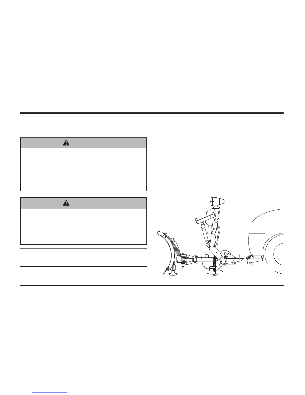
MOUNTING SNOWPLOW (ON)
NOTE: Use dielectric grease to prevent
corrosion on all connections.
MOUNTING SNOWPLOW TO VEHICLE
• Remove the electrical plug and disconnect
electrical plugs from storage position.
• Align vehicle receiver brackets with snowplow
horns and drive vehicle slowly forward until
snowplow horns fully seat inside receiver
brackets.
• Turn the vehicle ignition to the "OFF" position.
Plow
Horn
Receiver
Bracket
Lock Pin
Shoe
Handle
Stand
WARNING
Keep 8' clear of the blade drop zone when
it is being raised, lowered or angled. Do
not stand between the vehicle and blade
or directly in front of blade. If the blade
hits you or drops on you, you could be
seriously injured.
WARNING
Inspect snowplow components and bolts
for wear or damage whenever attaching
or detaching the snowplow. Worn or
damaged components could allow the
snowplow to drop unexpectedly.
Page 31
Lit. No. 49513, Rev. 00 32 August 15, 2011
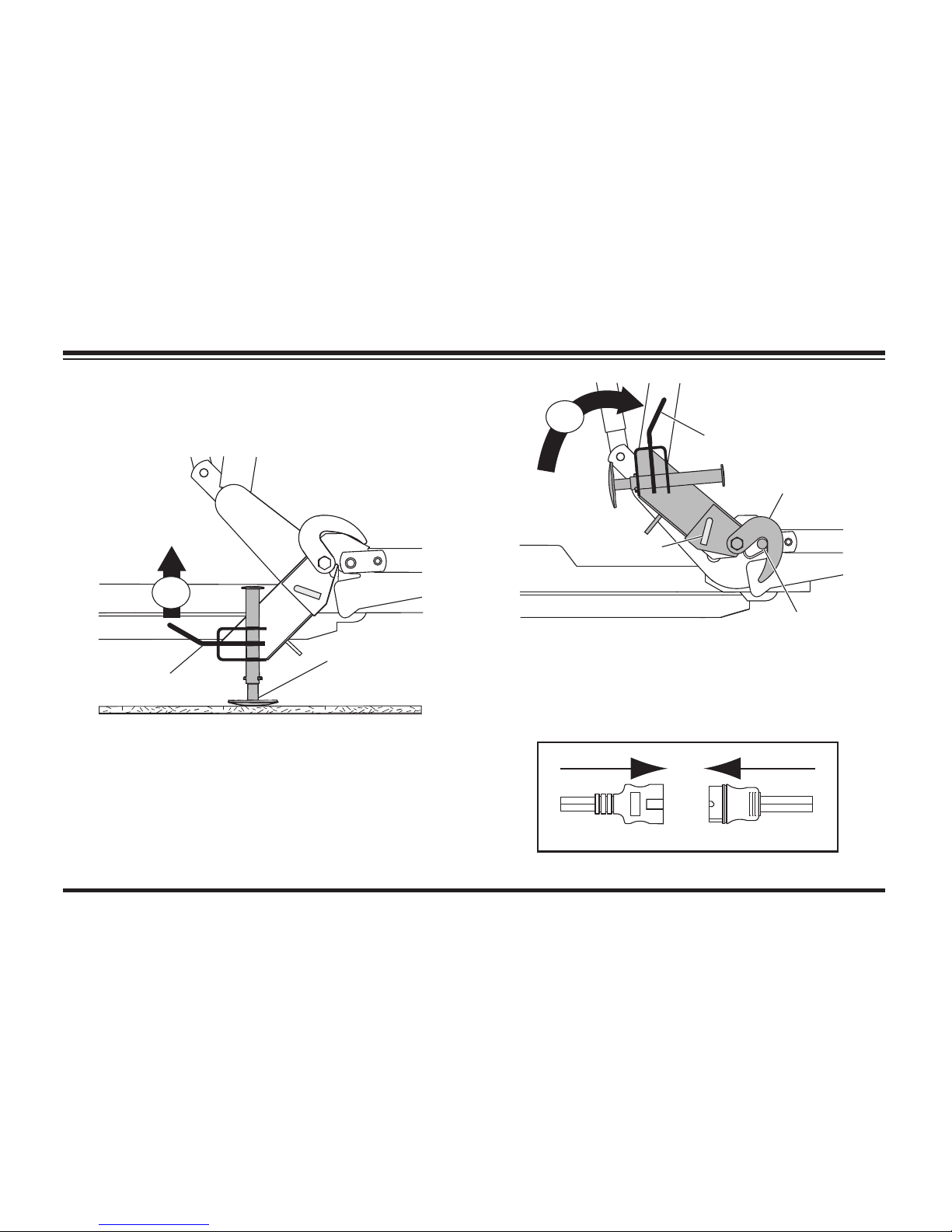
MOUNTING SNOWPLOW TO VEHICLE
1. After seating snowplow horns in receiver
brackets, pull handle up; shoe will lift off the
ground.
2. Pull and hold lock pin out; then rotate handle
UP and release lock pin. It must lock into
UPPER hole. Stand hook must grip receiver
pin.
3. Repeat Steps 1 and 2 on other side of
snowplow. (Not required for HTS™ blades.)
4. Connect electrical plugs.
ON
Shoe
Handle
ON
Receiver Pin
Stand Hook
Handle
(Pull)
Lock Pin
Page 32
Lit. No. 49513, Rev. 00 33 August 15, 2011
OPERATING YOUR SNOWPLOW
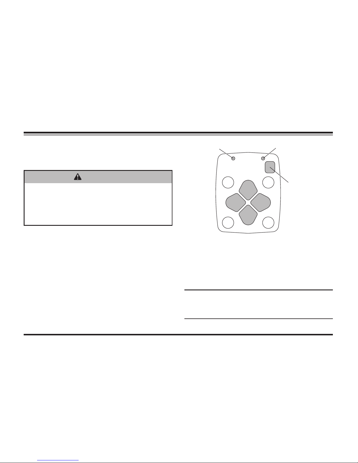
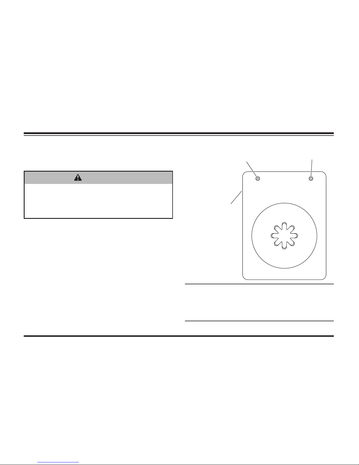
STRAIGHT BLADE CabCommand
HAND-HELD CONTROL
1. Turn the vehicle ignition switch to the "ON" or
"ACCESSORY" position.
2. Press the ON/OFF button on the control. The
power indicator light glows red, indicating the
control is ON. The power indicator light glows
red whenever the control and the vehicle
ignition switch are both ON and the electrical
connections to the snowplow are completed.
The ON/OFF button operates as an
emergency stop if required.
Function Time-Outs
All control functions, except LOWER/FLOAT, time
out (stop) automatically after a period of time. This
is to limit the amount of electrical energy required
from the vehicle.
NOTE: If control function times out before
desired blade movement is complete, release
button and press again.
RAISE
LOWER
R
L
ON/OFFFLOAT
1
43
2
Power Indicator
Light (red)
ON/OFF Button
(Emergency Stop)
FLOAT Light
(green)
WARNING
To prevent accidental movement of the
blade, always push the ON/OFF button
to switch the control OFF whenever
the snowplow is not in use. The power
indicator light will turn OFF.
Page 33

Lit. No. 49513, Rev. 00 34 August 15, 2011
OPERATING YOUR SNOWPLOW
Automatic Shutdown
The control will automatically turn OFF after being
idle for 20 minutes. To reactivate the control after
a shutdown, press the ON/OFF button.
Smooth Stop
The control automatically allows the blade to coast
to a stop when the button is released. This results
in smoother operation, reduces the shock to the
hydraulic system and increases hose and valve
life. See "FLEET FLEX Electrical System" in this
section for more information.
Control Functions
Raise, Lower, Float, Angle
The four diamond-shaped buttons in the center of
the control face, when pressed, will result in the
blade movements described in the table.
Function Description of Operation
RAISE
Press this button to raise the snowplow
and cancel the FLOAT mode. Function
times out after 3.5 seconds.
LOWER
Press this button to lower the snowplow.
Release the button to stop blade at
desired height.
FLOAT
†
Press the LOWER button and hold
3/4 second to activate this mode. The
FLOAT light in the upper left corner of the
control face will illuminate. The blade will
lower to the ground surface and follow the
contour of the surface as it dips or raises.
Function does not time out, but control
will shut down after 20 minutes of nonuse.
Press RAISE button momentarily to
cancel FLOAT. Angling left or right will not
interrupt (stop) the FLOAT function.
† FLOAT mode activates immediately when one-touch FLOAT
feature is enabled. See "One-Touch FLOAT" in this section
for more information.
Page 34

Lit. No. 49513, Rev. 00 35 August 15, 2011
Function Description of Operation
L
(Angle
Left)
Press this button to angle the blade
to the left. Function times out after
3.25 seconds.
R
(Angle
Right)
Press this button to angle the blade
to the left. Function times out after
3.25 seconds.
NOTE: If control function times out before
desired blade movement is complete, release
button and press again.
SECURITY GUARD™ System (1, 2, 3, 4)
The four round buttons located to the left and
right of the LOWER and RAISE buttons will
operate the SECURITY GUARD system. See
"SECURITY GUARD System" in this section for
more information.
OPERATING YOUR SNOWPLOW
Page 35
Lit. No. 49513, Rev. 00 36 August 15, 2011
OPERATING YOUR SNOWPLOW
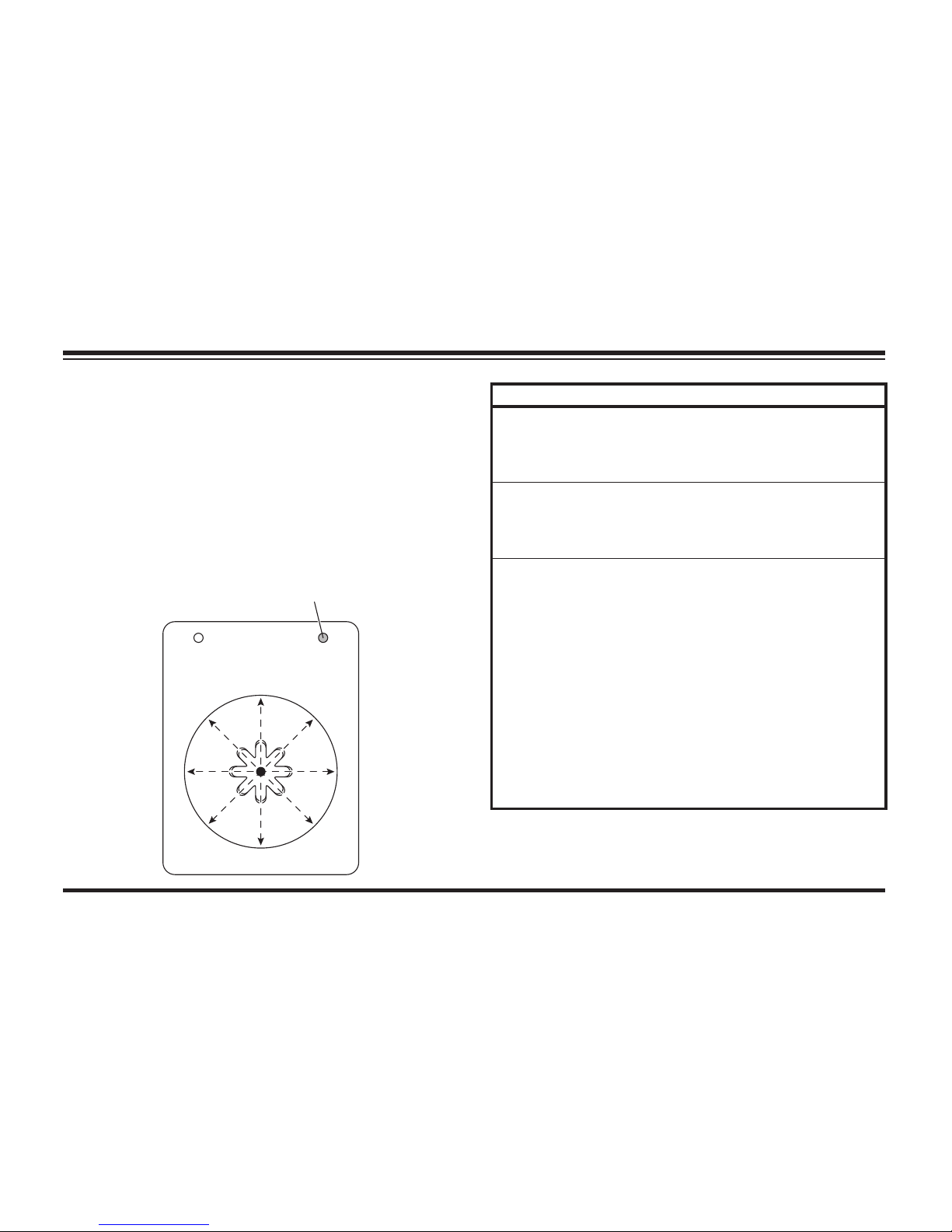
STRAIGHT BLADE
JOYSTICK CONTROL
1. Turn the vehicle ignition switch to the "ON" or
"ACCESSORY" position.
2. Move the ON/OFF switch on the side of
the control to the "ON" position. The power
indicator light glows red, indicating the control
is ON. The indicator light glows red whenever
the control and the vehicle ignition switch are
both ON and the electrical connections to the
snowplow are completed.
The ON/OFF switch operates as an
emergency stop if required.
WARNING
To prevent accidental movement of the
blade, always move the ON/OFF switch to
OFF whenever the snowplow is not in use.
The power indicator light will turn OFF.
L
R
RAISE
LOWER
ON/OFF FLOAT
12
34
Power Indicator
Light (red)
FLOAT Light
(green)
ON/OFF Switch
(Emergency Stop)
NOTE: If control function times out before
desired blade movement is complete, release
the lever to the center position, then move
back into the desired function.
Page 36

Lit. No. 49513, Rev. 00 37 August 15, 2011
OPERATING YOUR SNOWPLOW
Function Time-Outs
All control functions, except LOWER/FLOAT, time
out (stop) automatically after a period of time. This
is to limit the amount of electrical energy required
from the vehicle.
NOTE: If control function times out before
desired blade movement is complete, release
the lever to the center position, then move
back into the desired function.
Automatic Shutdown
The control will automatically turn OFF after being
idle for 20 minutes. To reactivate the control after
a shutdown, move the ON/OFF switch to OFF,
then back to ON.
Smooth Stop
The control automatically allows the blade to coast
to a stop when the lever returns to center position.
This results in smoother operation, reduces the
shock to the hydraulic system and increases
hose and valve life. See "FLEET FLEX Electrical
System" in this section for more information.
Control Lever Movement
From the center position, the control lever can
be moved in one of eight (8) directions to control
various movements of the snowplow blade.
To change from one movement of the blade to
another, the control lever must be moved back to
the center position before selecting the desired
function. Whenever the lever is released, it should
spring back into the center position to stop any
blade movement.
Page 37
Lit. No. 49513, Rev. 00 38 August 15, 2011
OPERATING YOUR SNOWPLOW
Control Functions
Raise, Lower, Float, Angle
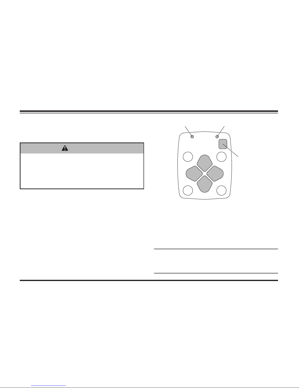
Moving the control lever in straight lines up and
down or from side to side on the control body will
result in the blade movements described in the
following tables.
L
R
RAISE
LOWER
ON/OFF FLOAT
12
34
FLOAT Light
(green)
Function Description of Operation
RAISE
Move the control lever toward the top of
the control body to raise the snowplow
and cancel the FLOAT mode. Function
times out after 3.5 seconds.
LOWER
Move the control lever toward the bottom
of the control body to lower the snowplow.
Release the lever to stop blade at desired
height.
FLOAT
†
Move the control lever to the LOWER
position and hold 3/4 second to activate
this mode. The FLOAT light in the upper
right corner of the control face will
illuminate. The blade will lower to the
ground surface and follow the contour of
the surface as it dips or raises. Function
does not time out; however, control will
shut down after 20 minutes of nonuse.
Move lever to the RAISE position
momentarily to cancel FLOAT. Angling left
or right will not interrupt (stop) the FLOAT
function.
† FLOAT mode activates immediately when one-touch FLOAT
feature is enabled. See "One-Touch FLOAT" in this section
for more information.
Page 38

Lit. No. 49513, Rev. 00 39 August 15, 2011
OPERATING YOUR SNOWPLOW
Function Description of Operation
L
(Angle Left)
Move the control lever straight to the left
to angle the blade left. Function times out
after 3.25 seconds.
R
(Angle
Right)
Move the control lever straight to the right
to angle the blade right. Function times
out after 3.25 seconds.
NOTE: If control function times out before
desired blade movement is complete, release
the lever to the center position, then move
back into the desired function.
SECURITY GUARD™ System (1, 2, 3, 4)
Moving the control lever from the center position
toward any of the four digits on the face of the
control body will operate the SECURITY GUARD
system. See "SECURITY GUARD System" in this
section for more information.
Page 39
Lit. No. 49513, Rev. 00 40 August 15, 2011
OPERATING YOUR SNOWPLOW
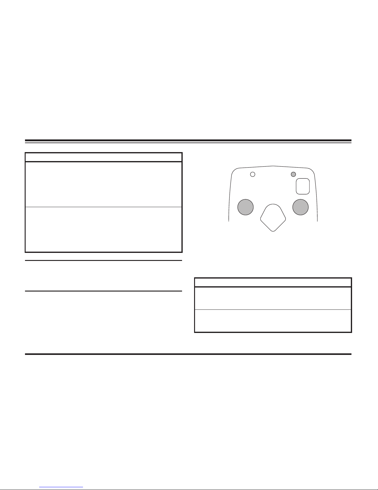
MVP PLUS™ & WIDE-OUT™
CabCommand HAND-HELD CONTROL
1. Turn the vehicle ignition switch to the "ON" or
"ACCESSORY" position.
2. Press the ON/OFF button on the control. The
power indicator light glows red, indicating the
control is ON. The power indicator light glows
red whenever the control and the vehicle
ignition switch are both ON and the electrical
connections to the snowplow are completed.
The ON/OFF button operates as an
emergency stop if required.
Function Time-Outs
All control functions, except LOWER/FLOAT, time
out (stop) automatically after a period of time. This
is to limit the amount of electrical energy required
from the vehicle.
NOTE: If control function times out before
desired blade movement is complete, release
button and press again.
WARNING
To prevent accidental movement of the
blade, always push the ON/OFF button
to switch the control OFF whenever
the snowplow is not in use. The power
indicator light will turn OFF.
RAISE
LOWER
R
L
ON/OFFFLOAT
1
3
2
4
S
C
O
O
P
R
E
T
R
A
C
T
W
I
N
G
W
I
N
G
Power Indicator
Light (red)
ON/OFF Button
(Emergency Stop)
FLOAT Light
(green)
Page 40

Lit. No. 49513, Rev. 00 41 August 15, 2011
OPERATING YOUR SNOWPLOW
Automatic Shutdown
The control will automatically turn OFF after being
idle for 20 minutes. To reactivate the control after
a shutdown, press the ON/OFF button.
Smooth Stop
The control automatically allows the blade to coast
to a stop when the button is released. This results
in smoother operation, reduces the shock to the
hydraulic system and increases hose and valve
life. See "FLEET FLEX Electrical System" in this
section for more information.
Control Functions
Raise, Lower, Float, Angle
The four diamond-shaped buttons in the center of
the control face, when pressed, will result in the
blade movements described in the table.
Function Description of Operation
RAISE
Press this button to raise the snowplow
and cancel the FLOAT mode. Function
times out after 3.5 seconds.
LOWER
Press this button to lower the snowplow.
Release the button to stop blade at
desired height.
FLOAT
†
Press the LOWER button and hold
3/4 second to activate this mode. The
FLOAT light in the upper left corner of the
control face will illuminate. The blade will
lower to the ground surface and follow the
contour of the surface as it dips or raises.
Function does not time out, but control will
shut down after 20 minutes of nonuse.
Press RAISE button momentarily to
cancel FLOAT. Angling left or right will not
interrupt (stop) the FLOAT function.
† FLOAT mode activates immediately when one-touch FLOAT
feature is enabled. See "One-Touch FLOAT" in this section
for more information.
Page 41
Lit. No. 49513, Rev. 00 42 August 15, 2011
OPERATING YOUR SNOWPLOW
Function Description of Operation
L
(Angle
Left)
With wings in a straight line, press the L
button to move both wings to the angle
left position to cast snow to the driver's
left side. The left wing retracts while
the right wing extends (MVP PLUS™).
Function times out after 3.25 seconds.
R
(Angle
Right)
With wings in a straight line, press the R
button to move both wings to the angle
right position to cast snow to the driver's
right side. The right wing retracts while the
left wing extends (MVP PLUS). Function
times out after 3.25 seconds.
NOTE: If control function times out before
desired blade movement is complete, release
button and press again.
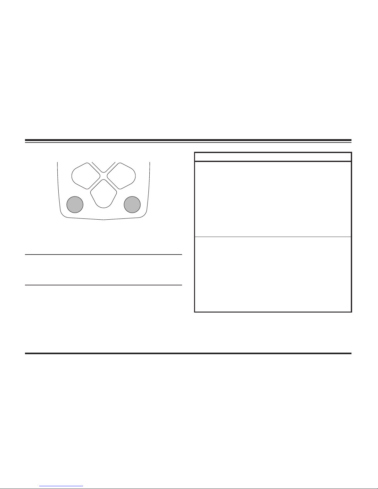
Scoop/Retract Blade Position
The two round buttons located to the left and right
of the RAISE button move both wings at the same
time into the blade positions described in the
following table.
Function Description of Operation
SCOOP
Press this button to extend both wings
forward into the scoop position. Function
times out after 5.5 seconds.
RETRACT
Press this button to draw both wings into
the fully retracted (vee) position. Function
times out after 4.5 seconds.
RAISE
ON/OFFFLOAT
12
S
C
O
O
P
R
E
T
R
A
C
T
Page 42
Lit. No. 49513, Rev. 00 43 August 15, 2011
OPERATING YOUR SNOWPLOW
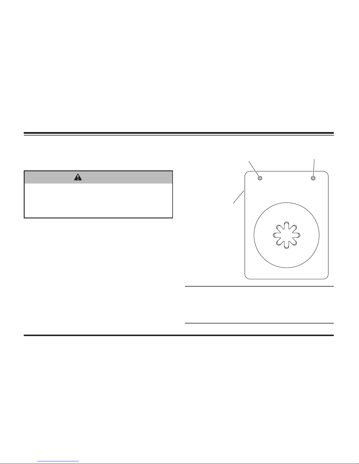
Wing Positions
The two round buttons located to the left and right of
the LOWER button move either wing independently
of the other as described in the following table.
NOTE: If control function times out before
desired blade movement is complete, release
button and press again.
SECURITY GUARD™ System (1, 2, 3, 4)
The four round buttons located to the left and
right of the LOWER and RAISE buttons will also
operate the SECURITY GUARD system. See
"SECURITY GUARD System" in this section for
more information.
Function Description of Operation
L WING
Press this button on the left side of the
control to move the left wing. The fi rst
time the button is pressed after the
control is turned ON or another function
is used, the wing will extend. Repeated
use of the same button, without using
another function, results in movement in
the opposite direction from the previous
movement. Function times out after
3.75 (OUT) or 3.25 seconds (IN).
R WING
Press this button on the right side of
the control to move the right wing. The
fi rst time the button is pressed after the
control is turned ON or another function
is used, the wing will extend. Repeated
use of the same button, without using
another function, results in movement in
the opposite direction from the previous
movement. Function times out after
3.75 (OUT) or 3.25 seconds (IN).
LOWER
RL
34
W
I
N
G
W
I
N
G
Page 43
Lit. No. 49513, Rev. 00 44 August 15, 2011
OPERATING YOUR SNOWPLOW
MVP PLUS™ & WIDE-OUT™
JOYSTICK CONTROL
1. Turn the vehicle ignition switch to the "ON" or
"ACCESSORY" position.
2. Move the ON/OFF switch on the side of
the control to the "ON" position. The power
indicator light glows red, indicating the control
is ON. The indicator light glows red whenever
the control and the vehicle ignition switch are
both ON and the electrical connections to the
snowplow are completed.
The ON/OFF switch operates as an
emergency stop if required.
WARNING
To prevent accidental movement of the
blade, always move the ON/OFF switch to
OFF whenever the snowplow is not in use.
The power indicator light will turn OFF.
34
21
L
R
RAISE
LOWER
ON/OFF
FLOAT
SCOOP
RETRACT
WING WING
Power Indicator
Light (red)
FLOAT Light
(green)
ON/OFF Switch
(Emergency Stop)
NOTE: If control function times out before
desired blade movement is complete, release
the lever to the center position, then move
back into the desired function.
Page 44

Lit. No. 49513, Rev. 00 45 August 15, 2011
OPERATING YOUR SNOWPLOW
Function Time-Outs
All control functions, except LOWER/FLOAT, time
out (stop) automatically after a period of time. This
is to limit the amount of electrical energy required
from the vehicle.
NOTE: If control function times out before
desired blade movement is complete, release
the lever to the center position, then move
back into the desired function.
Automatic Shutdown
The control will automatically turn OFF after being
idle for 20 minutes. To reactivate the control after
a shutdown, move the ON/OFF switch to OFF,
then back to ON.
Smooth Stop
The control automatically allows the blade to coast
to a stop when the lever returns to center position.
This results in smoother operation, reduces the
shock to the hydraulic system and increases
hose and valve life. See "FLEET FLEX Electrical
System" in this section for more information.
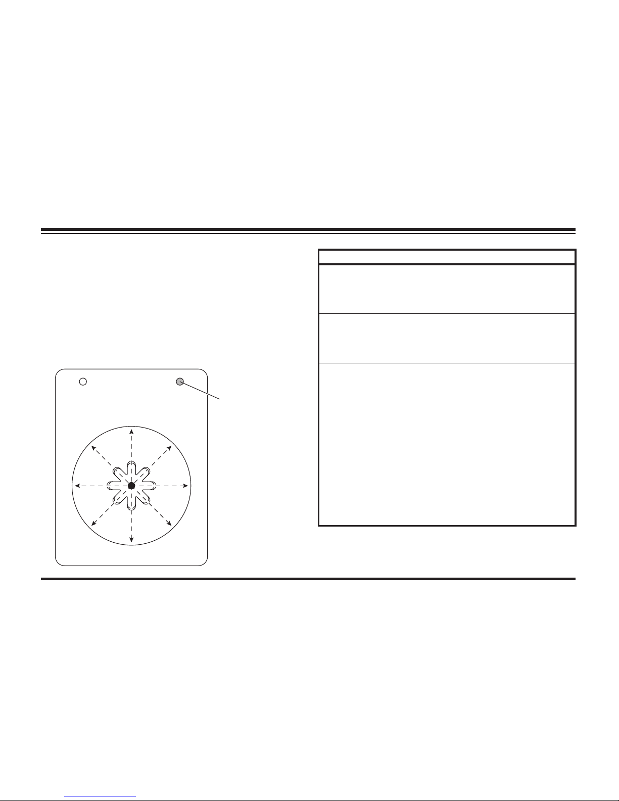
Control Lever Movement
From the center position, the control lever can
be moved in one of eight (8) directions to control
various movements of the snowplow blade.
To change from one movement of the blade to
another, the control lever must be moved back to
the center position before selecting the desired
function. Whenever the lever is released, it should
spring back into the center position to stop any
blade movement.
Page 45
Lit. No. 49513, Rev. 00 46 August 15, 2011
OPERATING YOUR SNOWPLOW
Control Functions
Raise, Lower, Float, Angle
Moving the control lever in straight lines up and
down or from side to side on the control body will
result in the blade movements described in the
following tables.
Function Description of Operation
RAISE
Move the control lever toward the top of
the control body to raise the snowplow
and cancel the FLOAT mode. Function
times out after 3.5 seconds.
LOWER
Move the control lever toward the bottom
of the control body to lower the snowplow.
Release the lever to stop blade at desired
height.
FLOAT
†
Move the control lever to the LOWER
position and hold 3/4 second to activate
this mode. The FLOAT light in the upper
right corner of the control face will
illuminate. The blade will lower to the
ground surface and follow the contour of
the surface as it dips or raises. Function
does not time out; however, control will
shut down after 20 minutes of nonuse.
Move lever to the RAISE position
momentarily to cancel FLOAT. Angling left
or right will not interrupt (stop) the FLOAT
function.
† FLOAT mode activates immediately when one-touch FLOAT
feature is enabled. See "One-Touch FLOAT" in this section
for more information.
34
21
L
R
RAISE
LOWER
ON/OFF
FLOAT
SCOOP
RETRACT
WING WING
FLOAT Light
(green)
Page 46

Lit. No. 49513, Rev. 00 47 August 15, 2011
OPERATING YOUR SNOWPLOW
Function Description of Operation
L
(Angle
Left)
With wings in a straight line, move the
control lever straight to the left to move
both wings to the angle left position to
cast snow to the driver's left side. The left
wing retracts while the right wing extends.
Function times out after 3.25 seconds.
R
(Angle
Right)
With wings in a straight line, move the
control lever straight to the right to move
both wings to the angle right position
to cast snow to the driver's right side.
The right wing retracts while the left
wing extends. Function times out after
3.25 seconds.
Scoop/Retract Blade Position
Moving the control lever from the center position
toward the word SCOOP or RETRACT on the face
of the control body will cause both wings to move
at the same time into the following blade positions.
Function Description of Operation
SCOOP
Move the control lever toward the word
SCOOP on the control face to extend both
wings forward into the scoop position.
Function times out after 5.5 seconds.
RETRACT
Move the control lever toward the
word RETRACT on the control face to
draw both wings into the fully retracted
(vee) position. Function times out after
4.5 seconds.
Page 47

Lit. No. 49513, Rev. 00 48 August 15, 2011
OPERATING YOUR SNOWPLOW
Wing Positions
Moving the control lever from the center position
toward the word WING on either side of the face
of the control body will cause either wing to move
independently of the other as described in the
following table.
NOTE: If control function times out before
desired blade movement is complete, release
the lever to the center position, then move
back into the desired function.
SECURITY GUARD™ System (1, 2, 3, 4)
Moving the control lever from the center
position toward any of the four digits on the
face of the control body will also operate
the SECURITY GUARD system. See
"SECURITY GUARD System" in this section for
more information.
Function Description of Operation
L WING
Move the control lever toward the left side
of LOWER on the control face to move
the left wing. The fi rst time the lever is
moved into the slot after the control is
turned ON or another function is used,
the wing will extend. Repeated use of
lever in the same slot, without using
another function, results in movement in
the opposite direction from the previous
movement. Function times out after
3.75 (OUT) or 3.25 seconds (IN).
R WING
Move the control lever toward the right
side of LOWER on the control face to
move the right wing. The fi rst time the
lever is moved into the slot after the
control is turned ON or another function is
used, the wing will extend. Repeated use
of lever in the same slot, without using
another function, results in movement in
the opposite direction from the previous
movement. Function times out after
3.75 (OUT) or 3.25 seconds (IN).
Page 48

Lit. No. 49513, Rev. 00 49 August 15, 2011
OPERATING YOUR SNOWPLOW
FLEET FLEX ELECTRICAL SYSTEM
Your U ltr aM o unt® system snowplow comes
standard with user-controlled programmable
features. These include:
• SECURITY GUARD™ electrical anti-theft
system;
• Smooth Stop;
• One-Touch FLOAT.
This section provides more information about each
feature, as well as instructions on how to enable
or disable them. These features are offered to
give you the ability to secure your snowplow and
customize your plowing experience.
Page 49

Lit. No. 49513, Rev. 00 50 August 15, 2011
OPERATING YOUR SNOWPLOW
SECURITY GUARD™ System
Activation & Establishing a
4-Digit Security Code
NOTE: The snowplow must be attached to
the vehicle, and all the electrical connections
must be connected prior to activating the
security code function.
The SECURITY GUARD feature was developed
as an electrical anti-theft system. The system
provides a deterrent from theft and/or nonpermitted use by allowing you to electronically
lock the snowplow's hydraulic functions.
All multiplex snowplow controls come equipped
with the SECURITY GUARD system. To use
this function, you must complete the "Activation"
process.
1. Turn the vehicle ignition switch to the "ON" or
"ACCESSORY" position. (It is not necessary
to start the vehicle.)
2. Verify the control power indicator is OFF. If the
power indicator light is red, the control is ON.
Move the ON/OFF switch to "OFF" or push the
ON/OFF button to turn the control OFF.
3. To activate the SECURITY GUARD mode,
move the control lever to the #1 position or
press the #1 button four consecutive times,
and then to the #4 position or the #4 button
four consecutive times (sequence: 1, 1, 1, 1,
4, 4, 4, 4). The green FLOAT light will fl ash
quickly and the red power indicator light will
turn ON, indicating the system is ready to
accept your 4-digit security code.
Enter your 4-digit security code by moving the
control lever to (or pressing the button for) any
of the eight following positions: UP, DOWN,
LEFT, RIGHT, 1, 2, 3 or 4.
Page 50

Lit. No. 49513, Rev. 00 51 August 15, 2011
OPERATING YOUR SNOWPLOW
Manual Unlock
If the SECURITY GUARD system is activated
and you are using a control with a different 4-digit
code than the established security code, you will
be required to manually enter the 4-digit security
code before operating a locked snowplow.
1. Turn the vehicle ignition to the "ON" or
"ACCESSORY" position.
2. Move the ON/OFF switch to the "ON" position
or push the ON/OFF button to switch the
control ON.
3. The power indicator light will fl ash rapidly,
indicating that the snowplow is locked.
4. Enter the 4-digit security code.
Once you have entered your 4-digit
security code, the FLOAT light will stop
fl ashing and The power indicator light will
turn OFF. This indicates that your 4-digit
security code is entered and stored in the
SECURITY GUARD™ system.
4. Once a 4-digit security code is established
and the plow/vehicle electrical connection are
lost/disconnected, the SECURITY GUARD
system will recognize any control that has
been programmed with the same 4-digit
security code. Any control not programmed
with the correct 4-digit security code will
require the user to enter the established
security code before activating the snowplow
(see the Manual Unlock procedure).
NOTE: If the control is turned ON prior to
completing the programming procedure, your
4-digit security code will be cancelled.
Page 51

Lit. No. 49513, Rev. 00 52 August 15, 2011
5. After entering the correct security code, the
power indicator light will change from fl ashing
rapidly to a solid light to indicate the snowplow
has been successfully unlocked.
NOTE: If the plow/vehicle electrical
connection is lost or disconnected, the
SECURITY GUARD™ system will reset,
requiring any control that is not programmed
with the established 4-digit security code to
manually re-enter the security code to activate
the snowplow.
Clearing an Established 4-Digit Security Code
1. Turn the vehicle ignition switch to the "ON" or
"ACCESSORY" position.
2. If the snowplow is locked (the control power
indicator light will be fl ashing at a fast rate),
unlock the snowplow by following the Manual
Unlock procedure.
3. Move the ON/OFF switch to the "OFF"
position or push the ON/OFF button to switch
the control OFF. Verify that the power indicator
light is OFF.
4. With the control OFF, move the control lever
to the #2 position or press the #2 button
four consecutive times, and then to the
#3 position or the #3 button four consecutive
times. This sequence (2, 2, 2, 2, 3, 3, 3, 3)
will clear the 4-digit security code from the
SECURITY GUARD system. The FLOAT light
will fl ash to indicate that the 4-digit security
code was cleared.
NOTE: To enter a new 4-digit security code
see Activation & Establishing a 4-Digit
Security Code.
OPERATING YOUR SNOWPLOW
Page 52
Lit. No. 49513, Rev. 00 53 August 15, 2011
Light Flash Indicators
POWER – Red Function
OFF Control is OFF
Solid ON Control is ON and active
Slow Flash No communication
Fast Flash Snowplow is locked—enter
4-digit security code to unlock
FLOAT – Green Function
Solid ON FLOAT function is active
Fast Flash Security code activation in
progress
Additional Notes
• The SECURITY GUARD™ system requires
any control (other than the one with the
assigned 4-digit security code) to enter
the security code before the snowplow
can be activated. Once the security code
is established, the SECURITY GUARD
system recognizes that a control with the
same security code is attached, and does
not require a manual unlock to activate the
snowplow. The system will recognize the
control as "safe" and will automatically unlock.
• The SECURITY GUARD system is only fully
functional with joystick controls PN 96800 &
96700 and hand-held controls PN 96900 &
96600.
• In the event that a snowplow is locked and
cannot be manually unlocked or reset, contact
your Authorized Dealer.
• REMINDER: Record your security code for
future reference.
OPERATING YOUR SNOWPLOW
Page 53

Lit. No. 49513, Rev. 00 54 August 15, 2011
Smooth Stop
Smooth stop, or "soft" stop, allows the blade to
coast to a stop when the button/lever is released.
The result is smoother operation, reduction in
shock to the hydraulic system and an increase in
hose and valve life.
While there are advantages to having this feature,
there are also advantages to temporarily disabling
this feature. For example, to allow for more precise
movements of the blade while operating in close
distances to buildings and other obstacles.
All controls come standard with this feature
ENABLED. To enable/disable this feature, perform
the following steps. Performing the sequence
multiple times will toggle the feature between
enabled and disabled.
Enable/Disable Procedure
1. Turn the vehicle ignition switch to the "ON" or
"ACCESSORY" position. (It is not necessary
to start the vehicle.)
2. Verify the control power indicator is OFF. If the
power indicator light is red, the control is ON.
Move the ON/OFF switch to "OFF" or push the
ON/OFF button to turn the control OFF.
3. Move and hold the control lever to the R
position or press and hold the R button while
turning the control ON. The power indicator
light will turn ON and the FLOAT light will
fl ash, indicating the status of the feature.
Light Flash Indicators
Light Description
POWER – Red Solid ON = Control is ON
FLOAT – Green 1 Flash = Smooth Stop Enabled
2 Flashes = Smooth Stop Disabled
OPERATING YOUR SNOWPLOW
Page 54
Lit. No. 49513, Rev. 00 55 August 15, 2011
OPERATING YOUR SNOWPLOW
One-Touch FLOAT
One-touch FLOAT immediately activates the
FLOAT mode and releases the blade to the
ground, without having to hold the button or lever
in LOWER. This can improve transition time when
backing up to plow forward again, eliminating the
time spent holding the control and waiting for the
blade to fully drop.
All controls come standard with this feature
DISABLED. To enable/disable this feature,
perform the following steps. Performing the
sequence multiple times will toggle the feature
between enabled and disabled.
Enable/Disable Procedure
1. Turn the vehicle ignition switch to the "ON" or
"ACCESSORY" position. (It is not necessary
to start the vehicle.)
2. Verify the control power indicator is OFF. If the
power indicator light is red, the control is ON.
Move the ON/OFF switch to "OFF" or push the
ON/OFF button to turn the control OFF.
3. Move and hold the control lever to the LOWER
position or press and hold the LOWER button
while turning the control ON. The power
indicator light will turn ON and the FLOAT light
will fl ash, indicating the status of the feature.
Light Flash Indicators
Light Description
POWER – Red Solid ON = Control is ON
FLOAT – Green 1 Flash = One-touch FLOAT Disabled
2 Flashes = One-touch FLOAT
Enabled
Page 55
Lit. No. 49513, Rev. 00 56 August 15, 2011
OPERATING YOUR SNOWPLOW
MVP PLUS™ BLADE POSITIONS
NOTE: For best road clearance during
transport, place the blade halfway between
the straight and retracted (vee) positions.
The scoop position is NOT RECOMMENDED
during transport.
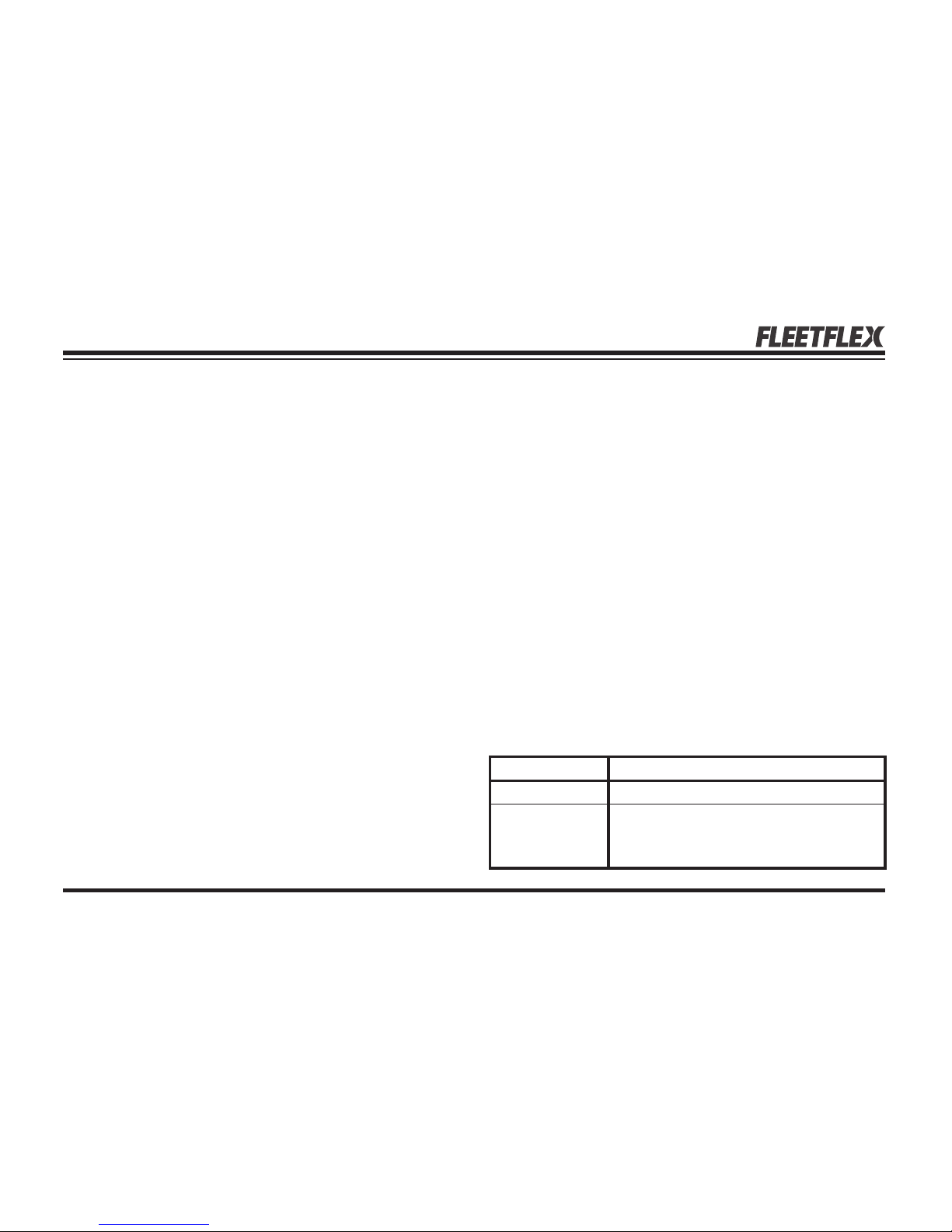
The MVP PLUS snowplow can be used in fi ve
basic plowing positions.
Straight Blade
Move both wings to form a straight blade for wide
path plowing or "stacking" snow.
Page 56
Lit. No. 49513, Rev. 00 57 August 15, 2011
OPERATING YOUR SNOWPLOW
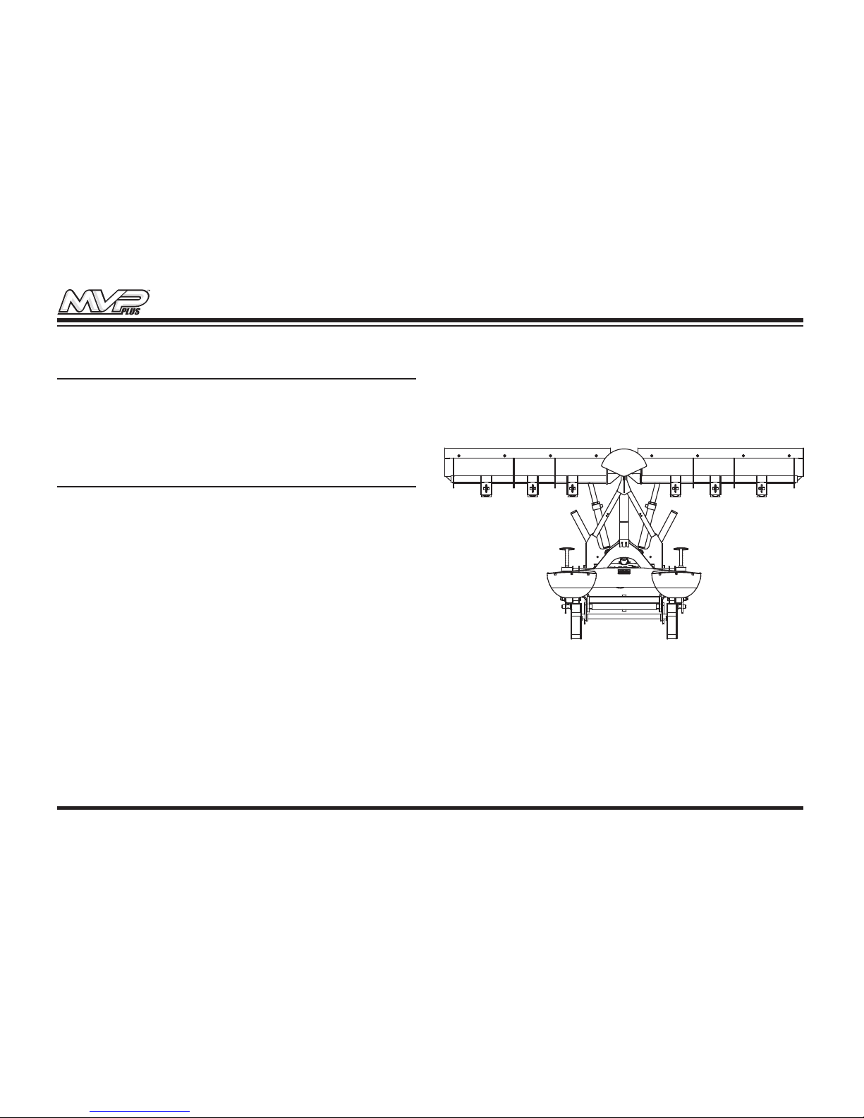
Angled Blade
Move one wing "OUT" and the other wing "IN" to
form an angled blade in either direction for general
plowing and widening.
Retracted (Vee) Blade
Move both wings "IN" towards the vehicle for
initial break through plowing and plowing paths or
walkways.
Page 57
Lit. No. 49513, Rev. 00 58 August 15, 2011
OPERATING YOUR SNOWPLOW
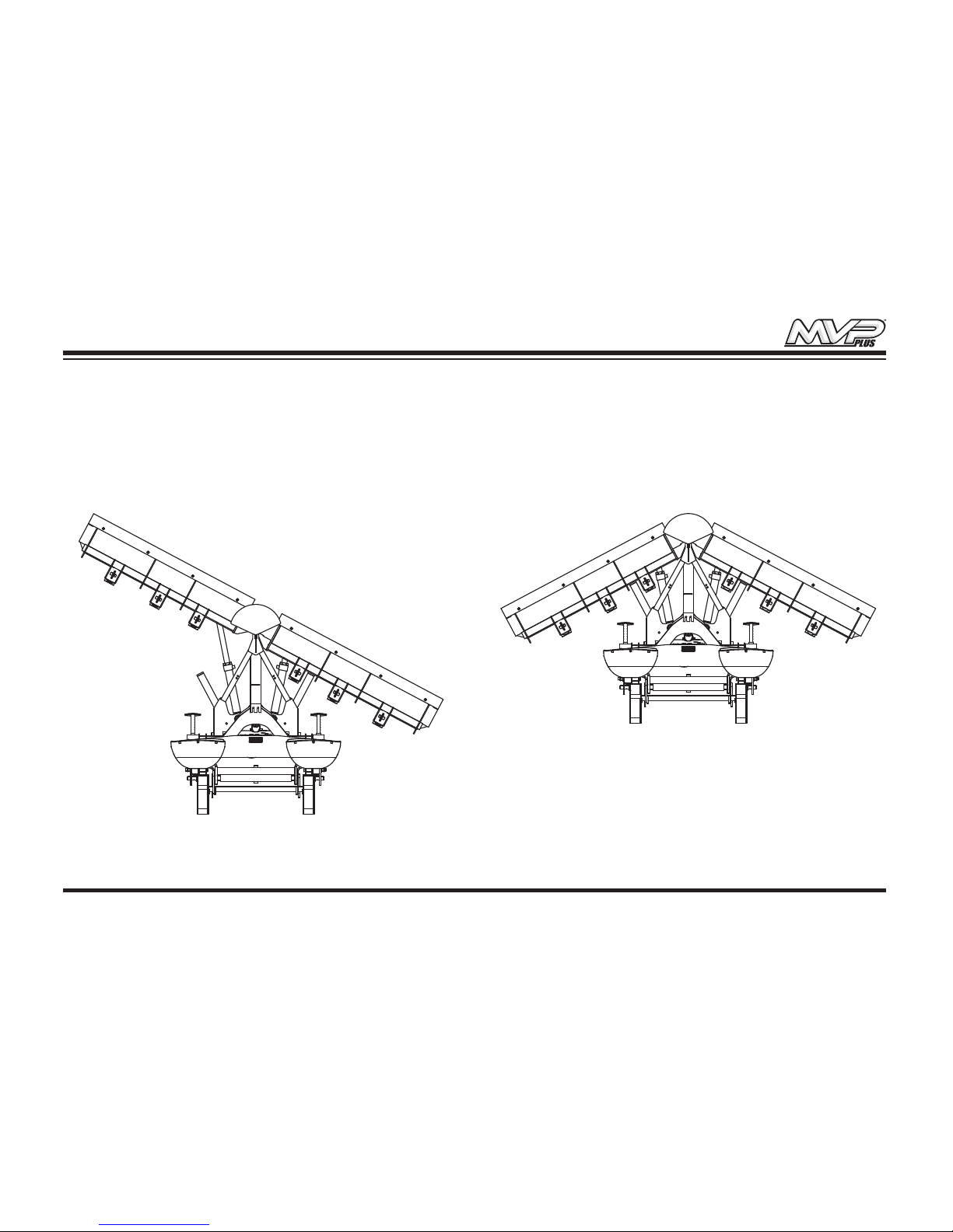
Scoop Blade
Move both wings "OUT" away from the vehicle
to form a scoop to "carry" snow with minimum
spilloff.
Dogleg Blade
Move one wing to straight blade position and the
other "OUT" to scoop blade position for clean up
of windrows.
Page 58
Lit. No. 49513, Rev. 00 59 August 15, 2011
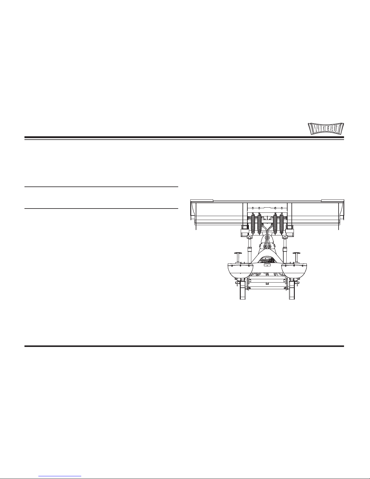
WIDE-OUT™ BLADE POSITIONS
The WIDE-OUT snowplow can be used in four
basic plowing positions.
NOTE: Always transport the WIDE-OUT
snowplow with both wings fully retracted.
OPERATING YOUR SNOWPLOW
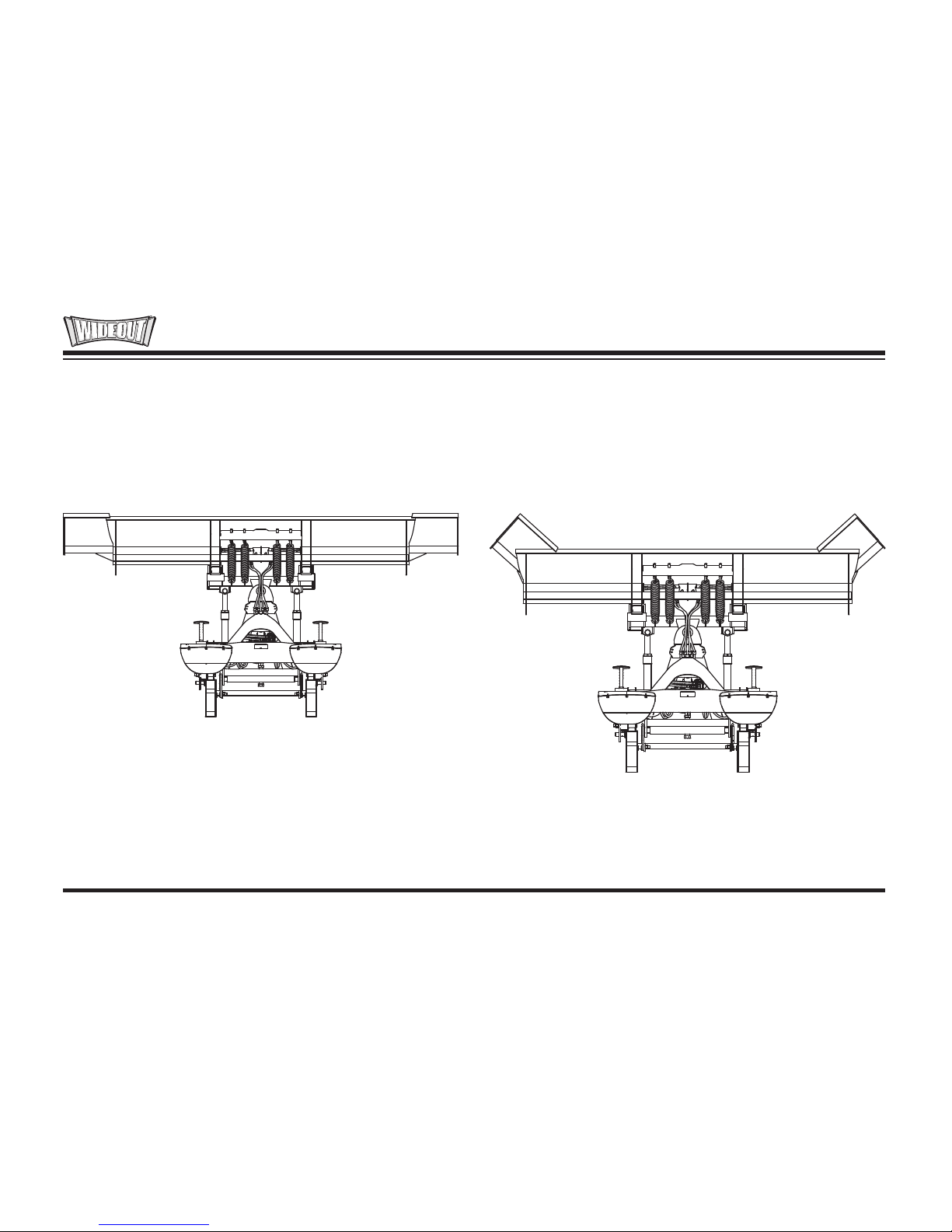
Retracted Blade
Move both wings "IN" to form a straight blade.
Page 59
Lit. No. 49513, Rev. 00 60 August 15, 2011
OPERATING YOUR SNOWPLOW
Extended Blade
Move both wings "OUT" straight for an extra-wide
blade for clearing large areas.
Scoop Blade
Move both wings "OUT" and ahead of the vehicle
to form a scoop to "carry" snow with minimum
spilloff.
Page 60
Lit. No. 49513, Rev. 00 61 August 15, 2011
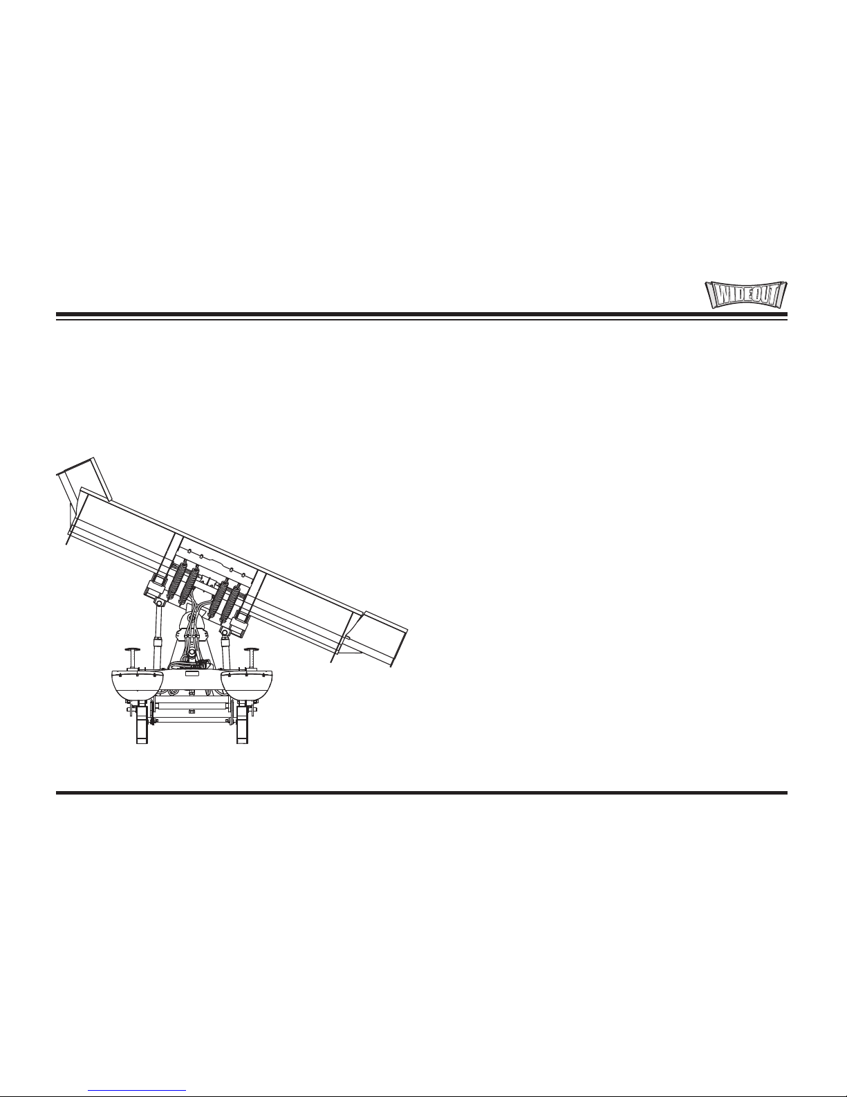
Dogleg Blade
Move one wing to extended position and the other
"OUT" to scoop blade position for clean up of
windrows.
OPERATING YOUR SNOWPLOW
Page 61

Lit. No. 49513, Rev. 00 62 August 15, 2011
OPERATING YOUR SNOWPLOW
SNOWPLOW HEADLAMP CHECK
With all electrical plugs connected, check the
operation of vehicle and snowplow headlamps.
Lights Results
Parking Lamps
Both vehicle and snowplow
lamps should be ON.
Right Turn Signal
Both vehicle and snowplow
lamps should be ON.
Left Turn Signal
Both vehicle and snowplow
lamps should be ON.
Connecting and disconnecting the electrical plugs
should switch between the vehicle and snowplow
headlamps as follows:
• Electrical plugs DISCONNECTED – Vehicle
headlamps function normally.
• Electrical plugs CONNECTED – Vehicle
headlamp functions transfer to the snowplow
headlamps. On some DRL systems, both the
vehicle and snowplow headlamps will function.
Aiming the Headlamps
• Aim the snowplow headlamps with the
snowplow mounted and raised in the transport
position. See "Aiming Headlamp Beams" in
the Maintenance section for instructions.
• Aim the vehicle headlamps with the snowplow
removed from the vehicle.
Page 62
Lit. No. 49513, Rev. 00 63 August 15, 2011
OPERATING YOUR SNOWPLOW
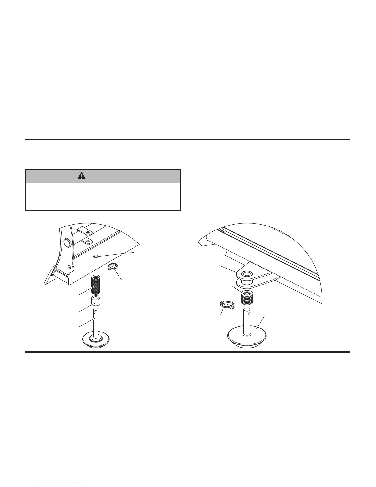
Washers
Spacer
Disc
Shoe
Linchpin
Shoe
Hole
Straight Blade
Linchpin
Shoe
Holder
Washers
Disc Shoe
Optional MVP PLUS™
& WIDE-OUT™
Disc Shoe Kit
DISC SHOE ADJUSTMENT
WARNING
Blade can drop unexpectedly. Place blade
on jack stands. Failure to do so could
result in serious personal injury.
Recommended Shoe Adjustments
For gravel surfaces: The bottom surface of the
shoe should be 1/4"–1/2" below the cutting edge.
For hard surfaces (concrete or asphalt): The
bottom surface of the shoe should be even with
the cutting edge.
Actual
confi guration
varies by
model
Actual
confi guration
varies by
model
Page 63

Lit. No. 49513, Rev. 00 64 August 15, 2011
OPERATING YOUR SNOWPLOW
Adjustment Procedure
1. Raise the blade 1' off the road surface, turn
the control OFF, and from in front of the blade,
place jack stands or sturdy blocking under the
cutting edge.
2. Turn the control ON and lower the blade onto
the jack stands or blocking. Turn the control
and vehicle ignition OFF.
3. Remove the linchpin, and slide the disc
shoe down and out of the shoe hole (straight
blades) or shoe holder (MVP PLUS™ and
WIDE-OUT™ blades).
4. Remove one or more washers from the shoe
stem, and reinstall the shoe into the shoe
hole/holder.
5. Place the removed washers onto the shoe
stem above the shoe hole/holder.
6. Reinstall the linchpin.
7. Turn the vehicle ignition to the "ON" position,
and turn the control ON. Raise the blade
slightly from the jack stands. Turn the control
OFF, and remove the jack stands.
8. Stand 8' clear of the blade drop zone when
checking the height adjustment of the cutting
edge to the road surface.
Page 64
Lit. No. 49513, Rev. 00 65 August 15, 2011
HYDRAULIC SYSTEM
The FloStat® hydraulic unit's valve manifold
includes relief valves to prevent damage to the
blade or vehicle if an obstacle is hit at either end
of the blade. The valves are preset at the factory
and do not need any adjustments unless the valve
manifold is serviced. When force against the
blade causes the pressure in an extended ram to
exceed set limits, the relief valve opens allowing
fl uid to escape and the ram retracts.
For hydraulic fl uid type and fi lling instructions, see
"Annual Fluid Change" under "Hydraulic System"
in the Maintenance section of this manual.
OPERATING YOUR SNOWPLOW
Straight Blades
Fill
Plug
Drain Plug
Reservoir
Valve
Manifold
Breathe
r
Quill
Motor
HTS™ Blades
Reservoir
Moto
r
Drain Plug
Valve
Manifold
Quill
Breather/
Fill Plug
MVP PLUS™ Blades
Breather
Quill
Reservoir
Valve
Manifold
Motor
Drain Cap
Fill
Plug
Motor
Relay
Breather
Fill
Plug
Quill
Valve
Manifold
Motor
Relay
Reservoir
Motor
WIDE-OUT™ Blades
Drain Cap
Page 65
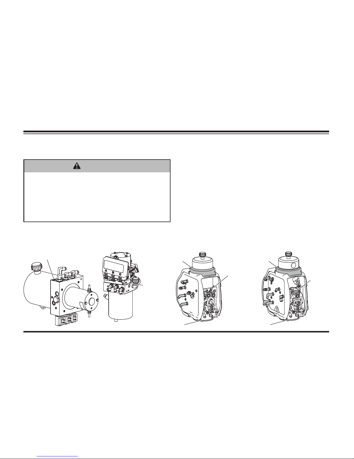
Lit. No. 49513, Rev. 00 66 August 15, 2011
OPERATING YOUR SNOWPLOW
WARNING
Keep 8' clear of the blade drop zone when
it is being raised, lowered or angled. Do
not stand between the vehicle and blade
or directly in front of blade. If the blade
hits you or drops on you, you could be
seriously injured.
BLADE DROP SPEED ADJUSTMENT
The quill in the valve manifold adjusts the blade
drop speed.
Quill
HTS™ Blades
Straight Blades
Quill
Top C over
Retainer
Bottom
Cover
Retainer
Quill
WIDE-OUT™ Blades
MVP PLUS™ Blades
Top C over
Retainer
Quill
Bottom
Cover
Retainer
Page 66

Lit. No. 49513, Rev. 00 67 August 15, 2011
OPERATING YOUR SNOWPLOW
Adjustment Procedure
1. Lower the blade to the ground before making
any adjustment.
2. Remove the hydraulic unit cover according to
the instructions for your blade:
HTS™ Blades: Remove the hydraulic unit
cover.
MVP PLUS™ and WIDE-OUT™ Blades: Lift
the hydraulic unit top cover retainer, remove
the bottom cover retainer and remove the side
cover.
Straight Blades: Follow the "Straight Blade
Hydraulic Unit Cover – Remove and Replace"
procedure in the Maintenance section of this
manual.
3. Turn the quill IN (clockwise) to decrease drop
speed. Turn the quill OUT (counterclockwise)
to increase drop speed.
4. Stand 8' clear of the blade drop zone when
checking adjustment.
5. Repeat Step 2 to reinstall the cover.
Page 67

Lit. No. 49513, Rev. 00 68 August 15, 2011
OPERATING YOUR SNOWPLOW
TRANSPORTING SNOWPLOW
NOTE: For MVP PLUS™ blades, use care
when driving or entering driveways with the
snowplow in the retracted (vee) position. The
outer ends of the cutting edges could contact
the ground.
NOTE: Always transport the WIDE-OUT™
snowplow with both wings fully retracted.
1. Completely raise the blade.
2. Adjust the blade height for maximum
snowplow headlamp illumination.
3. Adjust the blade to the straight position.
4. Turn the control OFF to lock the blade in
place.
NOTE: Overheating is unlikely under normal
driving conditions, but occasionally the
snowplow may be positioned where it defl ects
air away from the radiator. If this occurs,
stop the vehicle and raise, lower or angle the
snowplow slightly to correct overheating.
NOTE: Only the driver should be in the vehicle
cab when the snowplow is attached.
WARNING
Position blade so it does not block
headlamp beam.
Do not change blade position while
traveling. You could suddenly lower blade
accidentally.
CAUTION
Transport speed should not exceed
45 mph (72 km/h). Further reduce speed
under adverse travel conditions.
Page 68

Lit. No. 49513, Rev. 00 69 August 15, 2011
OPERATING YOUR SNOWPLOW
DRIVING AND PLOWING ON SNOW
AND ICE
Refer to vehicle owner's manual instructions for
driving in snow and ice conditions. Remember
when you drive on snow or ice, your wheels will
not get good traction. You cannot accelerate as
quickly, turning is more diffi cult and you will need
longer braking distance.
CAUTION
Drinking then driving or plowing is very
dangerous. Your refl exes, perceptions,
attentiveness and judgement can be
affected by even a small amount of alcohol.
You can have a serious or even fatal
collision if you drive after drinking. Please,
do not drink and then drive or plow.
Wet and hard packed snow or ice offers the worst
tire traction. It is very easy to lose control. You will
have diffi culty accelerating. If you do get moving,
you may have poor steering and diffi cult braking
which can cause you to slide out of control.
Here are some tips for driving in these conditions:
• Drive defensively.
• Do not drink, then drive or plow snow.
• Plow or drive only when you have good
visibility for operating a vehicle.
• If you cannot see well due to snow or icy
conditions, you will need to slow down and keep
more space between you and other vehicles.
• Slow down, especially on higher speed roads.
Your headlamps can light up only so much
road ahead.
Page 69
Lit. No. 49513, Rev. 00 70 August 15, 2011
OPERATING YOUR SNOWPLOW
• If you are tired, pull off in a safe place and rest.
• Keep your windshield and all glass on your
vehicle clean to see around you.
• Dress properly for the weather. Wear layers
of clothing, as you get warm you can take off
layers.
CAUTION
Wear a seat belt when plowing snow.
Hidden obstructions could cause the
vehicle to stop suddenly resulting in
personal injury.
CAUTION
Flag any obstructions that are hard to
locate under snow to prevent damage to
product or property.
WARNING
Never plow snow with head out the vehicle
window. Sudden stops or protruding
objects could cause personal injury.
PLOWING SNOW
Page 70
Lit. No. 49513, Rev. 00 71 August 15, 2011
OPERATING YOUR SNOWPLOW
NOTE: Only the driver should be in the vehicle
cab when the snowplow is attached.
CAUTION
Never stack snow with the blade angled.
This could damage the snowplow or the
vehicle bumper.
CAUTION
Plowing speed should not exceed 10 mph
(16 km/h).
General Instructions
1. Before plowing, make sure you know of any
obstructions hidden beneath the snow such as
bumper stops in parking lots, curbs, sidewalk
edges, shrubs, fences or pipes sticking up
from the ground. If unfamiliar with the area to
be plowed, have someone familiar with the
area point out obstacles.
2. If possible and you have good visibility, plow
during the storm rather than letting snow
accumulate.
3. Do not exceed 10 mph (16 km/h) when
plowing snow.
4. When you are stacking snow, begin raising
the blade as you come close to the stack. This
will let the blade ride up the stack.
Page 71

Lit. No. 49513, Rev. 00 72 August 15, 2011
OPERATING YOUR SNOWPLOW
Hard-Packed Snow
1. Raise the disc shoes so that the cutting edge
comes into direct contact with the pavement.
2. Use lowest gear to place maximum power
behind cutting edge.
3. An angled blade is more effective for removing
hard-packed snow.
Deep Snow
1. For straight blades, shear off top layers by
plowing with the blade raised 3"–4" for the
initial pass. For MVP PLUS™ blades, move
the blade into the fully retracted (vee) position
and make an initial pass.
2. Bite into the edges using only partial blade
width until job is cut down to size for full blade
plowing.
Rule of thumb:
6" of snow — plow with entire blade width;
9" of snow — plow with 3/4 blade width;
12" of snow — plow with 1/2 of the blade.
For WIDE-OUT™ blades in Scoop position,
plow all depths with entire blade width.
Experience and "feel" are the best guides.
3. When plowing deep snow, be sure to keep
vehicle moving.
4. Ballast is suggested for maximum traction.
Secure ballast behind the rear wheels. Do not
exceed vehicle's GVWR and GAWR.
5. For increased traction use tire chains where legal.
Page 72

Lit. No. 49513, Rev. 00 73 August 15, 2011
OPERATING YOUR SNOWPLOW
Clearing Driveways
1. Head into the driveway with the blade angled
and plow the snow away from any buildings.
Widen driveway by rolling snow away from any
buildings.
2. If a building is at the end of the driveway, plow
to within a vehicle length of the building. Push
as much snow as possible off the driveway.
3. With a raised blade, drive through remaining
snow to building. Drop blade and "back drag"
snow away from the building at least one
vehicle length. Repeat if necessary.
4. Back vehicle to the building and plow forward,
removing the remaining snow from the
driveway. Check municipal ordinances for
proper disposal of snow.
Clearing Parking Lots
1. Clear areas in front of buildings fi rst. With
blade raised, drive up to the building. Drop
blade and "back drag" the snow away from
building. When snow is clear of the buildings,
turn the vehicle around and push snow away
from the buildings towards outer edges of
lot. Back drag edges are available as an
accessory for select snowplow models.
2. Plow a single path down the center in the
lengthwise direction.
3. With the blade in the scoop, angle or dogleg
position, plow successive strips lengthwise
until the area is cleared and snow is "stacked"
around the outer edges.
4. If snow is too deep to clear in above manner,
clear main traffi c lanes as much as possible.
Page 73

Lit. No. 49513, Rev. 00 74 August 15, 2011
OPERATING YOUR SNOWPLOW
PARKING WITH SNOWPLOW
ATTACH ED
Whenever you park your vehicle, completely lower
the blade to the ground.
TOWING DISABLED OR STUCK
VEHICLE
Do not use any snowplow components as an
attaching point when retrieving, towing or winching
a disabled or stuck vehicle.
WARNING
Lower blade when vehicle is parked. Keep
8' clear of blade drop zone. Temperature
changes could change hydraulic pressure,
causing the blade to drop unexpectedly or
damaging hydraulic components. Failure
to do this could result in serious personal
injury.
Page 74

Lit. No. 49513, Rev. 00 75 August 15, 2011
REMOVING SNOWPLOW FROM VEHICLE & STORAGE
WARNING
Keep 8' clear of the blade drop zone when
it is being raised, lowered or angled. Do
not stand between the vehicle and blade
or directly in front of blade. If the blade
hits you or drops on you, you could be
seriously injured.
WARNING
Inspect snowplow components and
fasteners for wear or damage whenever
mounting or removing the snowplow.
Worn or damaged components could
allow the snowplow to drop unexpectedly.
REMOVING SNOWPLOW (OFF)
CAUTION
Store PRO PLUS®, PRO-PLOW® Series 2
and MIDWEIGHT™ A-frame in a horizontal
position. This will prevent water from
collecting and freezing in shock absorber.
Page 75
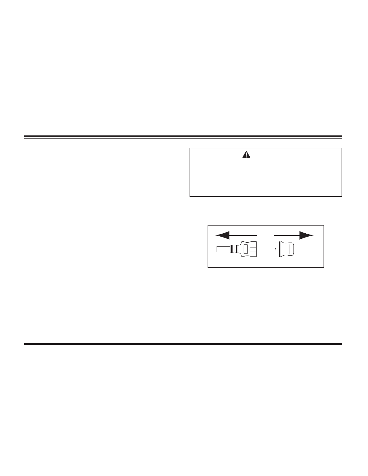
Lit. No. 49513, Rev. 00 76 August 15, 2011
REMOVING SNOWPLOW FROM VEHICLE & STORAGE
1. After lowering blade and turning control OFF,
disconnect the electrical plugs.
During the off-season, the control can be
removed. Disconnect the connector in the cab and
store the control in the glove box of the vehicle.
• Drive the vehicle to the desired snowplow
storage location.
• Adjust straight and WIDE-OUT™ blades to the
straight position or MVP PLUS™ blades to the
fully retracted (vee) position.
• Lower the blade to the ground.
• Turn the vehicle ignition to the "OFF" position.
CAUTION
On 2-plug electrical systems, plug covers
shall be used whenever snowplow is
disconnected. Vehicle Battery Cable is
12-volt unfused source.
Page 76
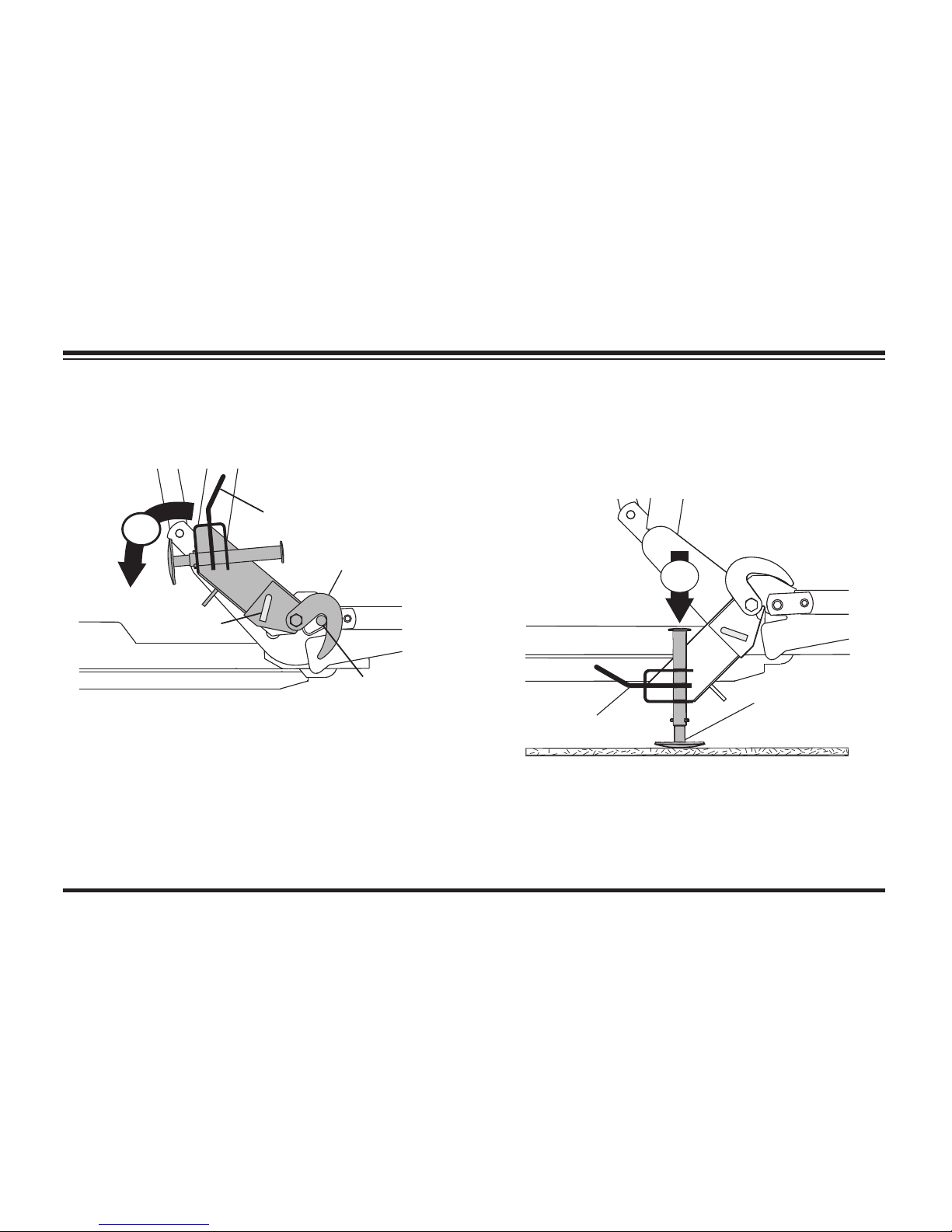
Lit. No. 49513, Rev. 00 77 August 15, 2011
2. Pull and hold lock pin out; then rotate handle
DOWN and release lock pin. It must lock into
LOWER hole.
3. Push down top of shoe; shoe will be on the
ground. Repeat Steps 2 and 3 on other side
of snowplow (not required for HTS™ blades).
Back vehicle away.
OFF
Receiver Pin
Stand Hook
Handle
(Pull)
Lock Pin
OFF
Shoe
Handle
REMOVING SNOWPLOW FROM VEHICLE & STORAGE
Page 77

Lit. No. 49513, Rev. 00 78 August 15, 2011
NOTE: After each use of the snowplow,
reapply dielectric grease to the electrical
plugs to maintain the protective coating on the
terminals.
NOTE: Place electrical plugs in storage
position. Insert the plow cable and headlamp
harness into the cable boot on the lift frame.
Install plug covers on the vehicle cable and
headlamp harness.
REMOVING SNOWPLOW FROM VEHICLE & STORAGE
STORAGE
Your snowplow is designed to be moved into
a storage location using your vehicle and plow
attaching system. For easier attaching of the
snowplow, store it on a hard, level surface.
Page 78

Lit. No. 49513, Rev. 00 79 August 15, 2011
MAINTENANCE
AIMING HEADLAMP BEAMS
Tighten headlamp fasteners to 45 ft-lb once
correct visual aim is achieved.
1. Place vehicle on a level surface 25 feet
in front of a matte-white screen, such
as a garage door. The screen should be
perpendicular both to the ground and to the
vehicle centerline.
2. The vehicle should be equipped for normal
operation. The snowplow blade should be in
place and in raised position. Below are steps
listed by the Society of Automotive Engineers
(SAE) pertinent to headlamp aiming in
specifi cation #SAE J599d.
3. Prepare vehicle for headlamp aim or
inspection. Before checking beam aim, the
inspector will:
a. Remove ice or mud from under fenders.
b. Set tire infl ation pressures to the values
specifi ed on vehicle information label.
c. Check springs for sag or broken leaves.
d. See that there is no load in the vehicle
other than the driver and ballast as
specifi ed in the Selection List.
e. Check functioning of any automatic
vehicle leveling systems and specifi c
manufacturer's instructions pertaining to
vehicle preparation for headlamp aiming.
f. Clean lenses.
g. Check for bulb burnout and proper beam
switching.
h. Stabilize suspension by rocking vehicle
sideways.
Page 79
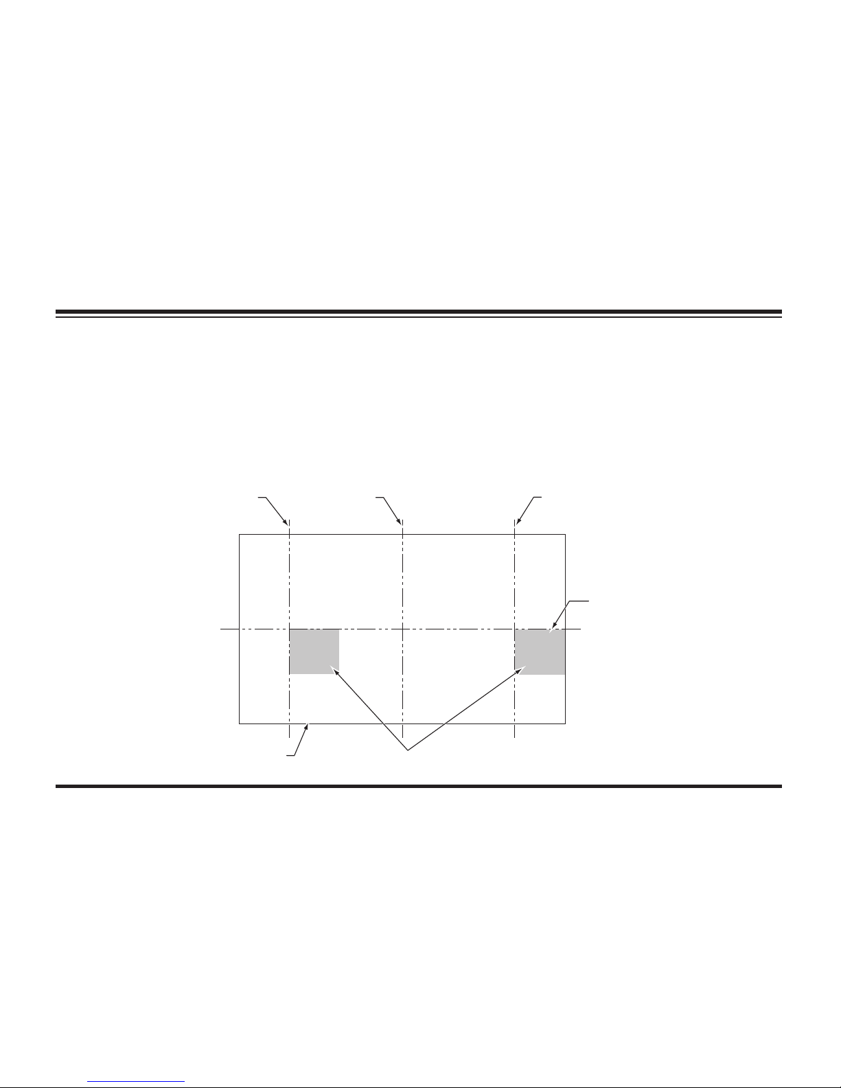
Lit. No. 49513, Rev. 00 80 August 15, 2011
MAINTENANCE
4. Mark (or tape) the vertical centerline of
the snowplow headlamps and the vertical
centerline of the vehicle on the screen. Mark
the horizontal centerline of the snowplow
headlamps on the screen (distance from
ground to snowplow headlamp centers).
5. Align the top edge of the high intensity zone
of the snowplow lower beam below the
horizontal centerline and the left edge of the
high intensity zone on the vertical centerline
for each snowplow headlamp. (Refer to
diagram below.)
Vertical Centerline ahead of
DS Snowplow Headlamp
Align with Vehicle
Centerline
Vertical Centerline ahead of
PS Snowplow Headlamp
Screen Located 25 Feet
from Snowplow Headlamps
Horizontal Centerline
of Snowplow Headlamps
High Intensity Zones of Snowplow Headlamps on Low Beam
Page 80
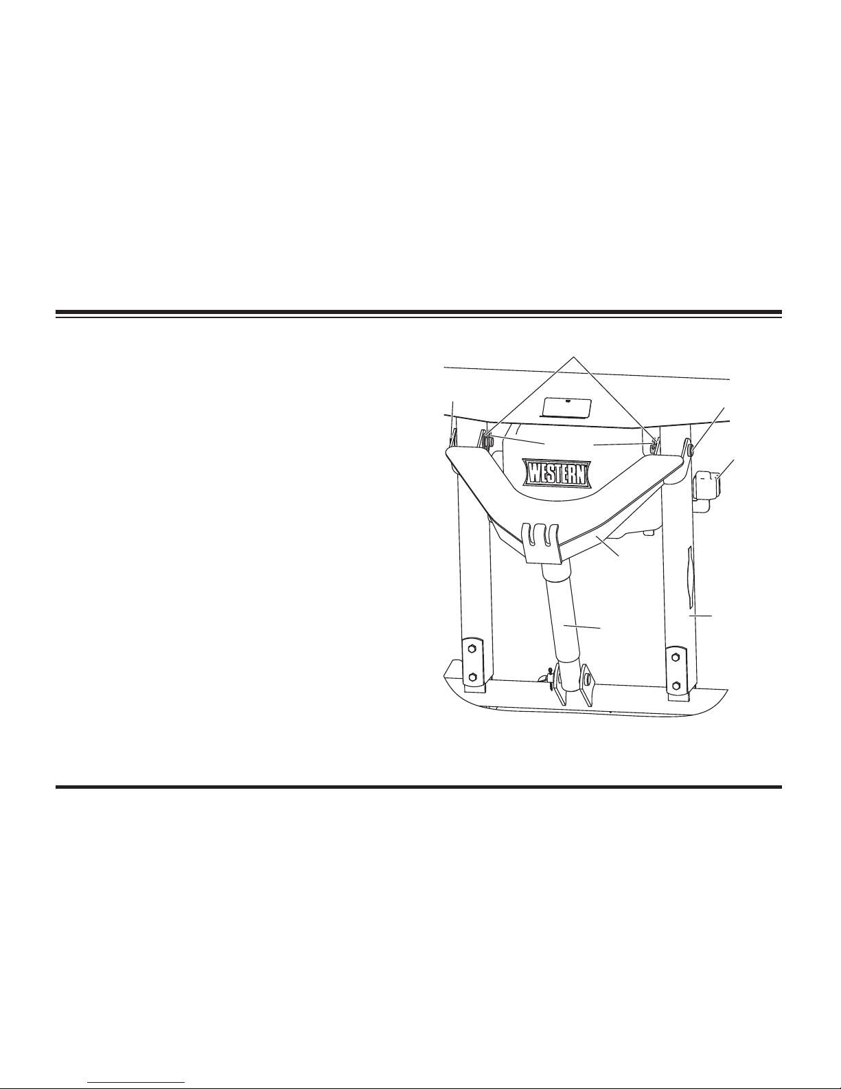
Lit. No. 49513, Rev. 00 81 August 15, 2011
MAINTENANCE
Washer
Hairpin
Cotter
Pin
Pin
Lift
Ram
Lift
Frame
Lift
Arm
Cable
Boot
STRAIGHT BLADE HYDRAULIC UNIT
COVER – REMOVE AND REPLACE
Snowplow Attached to Vehicle
1. Lower the blade to the ground. Place the
control in FLOAT, fully collapsing lift ram. Turn
the control OFF.
2. Remove the two hairpin cotters, washers and
pins attaching the lift arm to the lift frame.
3. Pivot the lift arm and lift ram forward and
remove or replace the cover.
4. Reassemble the lift arm to the lift frame with
the pins, washers and hairpin cotters removed
in Step 2.
Page 81
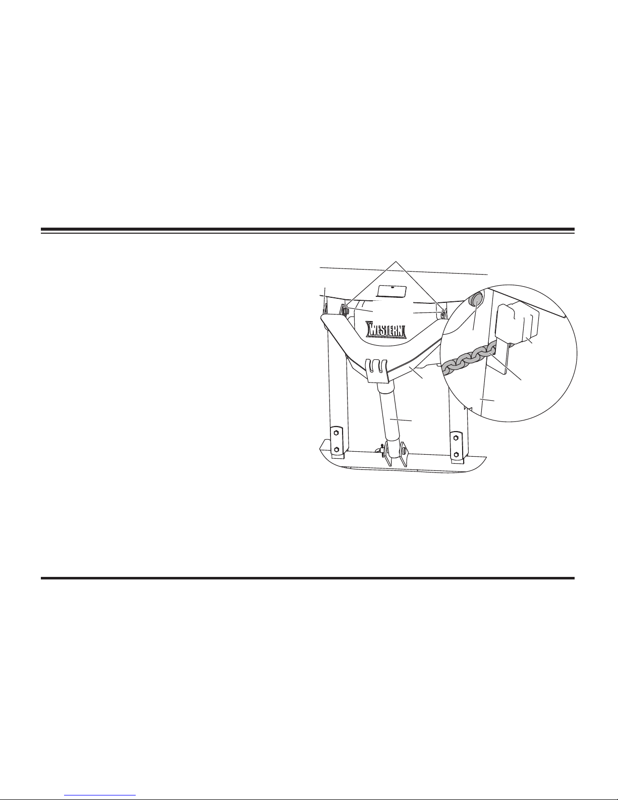
Lit. No. 49513, Rev. 00 82 August 15, 2011
MAINTENANCE
Snowplow Not Attached to Vehicle
1. Tilt the lift frame forward to create slack in the
lift chains. On the driver-side lift chain, mark
the link attaching it to the lift arm.
2. Unhook the driver-side lift chain from the lift
arm, remove the slack and hook the chain
in the slot between the cable boot and the
driver's side of the lift frame.
3. Remove the two hairpin cotters, washers and
pins attaching the lift arm to the lift frame.
4. Pivot the lift arm and lift ram forward and
remove or replace the cover.
5. Reassemble the lift arm to the lift frame with
the pins, washers and hairpin cotters removed
in Step 3.
6. Unhook the driver-side lift chain from the lift
frame and hook the marked chain link onto the
lift arm.
Washer
Hairpin
Cotter
Pin
Pin
Lift
Ram
Lift
Frame
Lift
Arm
Cable
Boot
DS Lift
Chain
Page 82

Lit. No. 49513, Rev. 00 83 August 15, 2011
PRESEASON CHECK
Before the snow season, check your equipment to
make sure it's in working condition. Here are some
tips for getting your equipment ready:
• Clean and tighten all electrical connections
and coat with dielectric grease to prevent
corrosion.
• Check hydraulic system for leaks and cracked
or damaged hoses.
MAINTENANCE
WARNING
Lower blade when vehicle is parked. Keep
8' clear of blade drop zone. Temperature
changes could change hydraulic pressure,
causing the blade to drop unexpectedly or
damaging hydraulic components. Failure
to do this could result in serious personal
injury.
• Drain hydraulic system and refi ll with
recommended hydraulic fl uid. For hydraulic
fl uid type and fi lling instructions, see "Annual
Fluid Change" under "Hydraulic System" in the
Maintenance section of this manual.
• Replace worn or damaged parts.
• Check all mounting points and tighten
fasteners, on both snowplow and vehicle.
Verify all cotter pins are in place.
• Repaint blade assembly and attachments, as
necessary, to protect the metal.
• Install auxiliary and fl ashing lights for
compliance and visibility in accordance with
local regulations.
• Check headlamps, auxiliary lights, heater and
windshield wipers for proper operation.
• Inspect and test your battery. Recharge or
replace as necessary.
Page 83

Lit. No. 49513, Rev. 00 84 August 15, 2011
MAINTENANCE
• Ballast may be necessary, or benefi cial, on
some vehicles to provide maximum traction,
braking and handling.
• Any ballast material (such as sand and blocks)
must be solidly secured to the vehicle preventing
it from moving under harsh plowing conditions.
POSTSEASON MAINTENANCE
NOTE: Coat all electrical connections with
dielectric grease.
• Clean and paint blade and components as
needed.
• Always store MVP PLUS snowplow with
blades in retracted (vee) position. This
exposes the minimum amount of angle
ram rod, and captures the least amount of
hydraulic fl uid in the system.
• Be sure lift ram is fully collapsed so the rod is
not exposed. (Not required for HTS™ blades.)
• Apply general purpose petroleum grease
to exposed chrome surfaces of the rams to
prevent rust.
• Lubricate all pivot points (for example, stand
lock pin assembly and lower spring anchor)
with general purpose petroleum grease.
CAUTION
Servicing the MVP PLUS™ trip springs
without special tools and knowledge
could result in personal injury. See your
authorized WESTERN® outlet for service.
Page 84
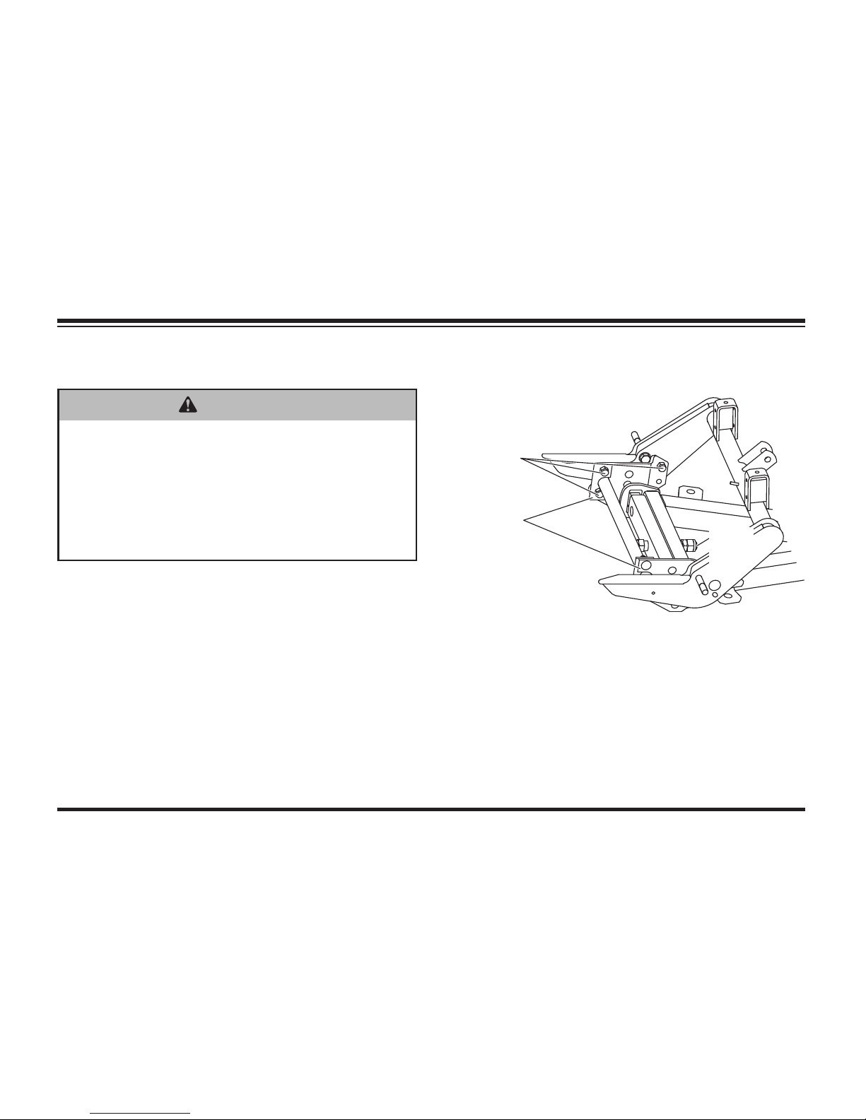
Lit. No. 49513, Rev. 00 85 August 15, 2011
MAINTENANCE
MAINTENANCE AND ADJUSTMENT
Your W ESTE R N® snowplow is designed for
rugged, dependable service. Though, like the
vehicle on which it is mounted, it needs regular
care and maintenance.
Check the following before and frequently during
the plowing season:
1. Make sure all fasteners, mounting bolts and
hydraulic connections are tight. Pay particular
attention to pivot plate fasteners and the
1" pivot bolt.
2. Make sure all electrical connections including
grounds are clean, tight, free of rust or
corrosion and are coated with dielectric grease.
3. Check all plugs and seals for hydraulic fl uid
leaks. Repair as necessary.
Pivot Plate
Fasteners
Pivot
Plates
Pivot
Bolt
WARNING
Lower blade when vehicle is parked. Keep
8' clear of blade drop zone. Temperature
changes could change hydraulic pressure,
causing the blade to drop unexpectedly or
damaging hydraulic components. Failure
to do this could result in serious personal
injury.
Page 85

Lit. No. 49513, Rev. 00 86 August 15, 2011
MAINTENANCE
4. Replace the cutting edge when it is worn to
the bottom of the blade.
MVP PLUS™ Cutting Edge: To equalize
wear, refer to the leveling adjustment
procedure in the following cutting edge
section.
5. Straight Blade and WIDE-OUT™ Trip
Spring Adjustment: To adjust trip spring
tension, adjust the eyebolts located at the top
of the blade. Loosen the locknut (nut closest to
the spring), and tighten the adjusting nut (nut
farthest from the spring) until the coils begin to
separate. When tension is properly adjusted,
a sheet of paper should pass between the
second and third coils. When the proper
tension is reached, tighten locknut.
6. Blade Finish: If the powder-coated fi nish is
nicked or scratched, repair the surface and
paint with WESTERN
®
red or black paint in
aerosol or quart can.
Page 86
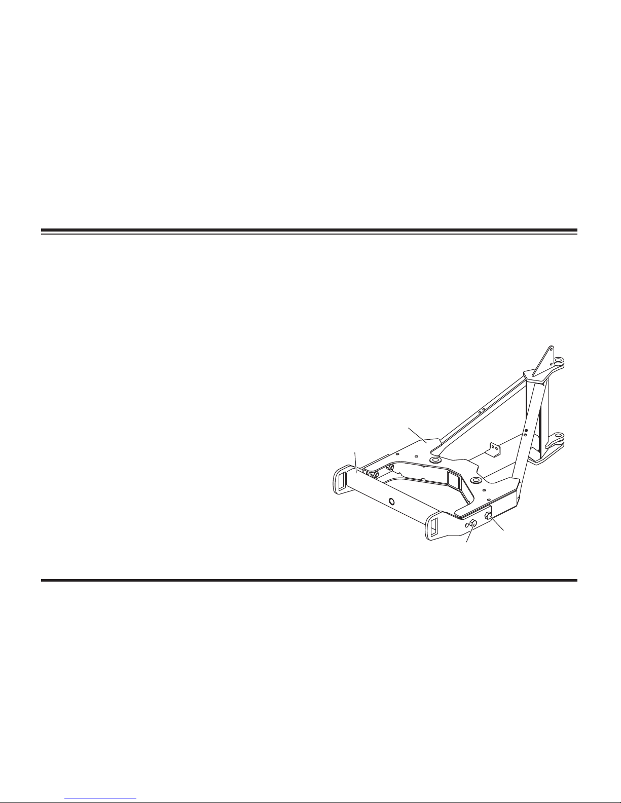
Lit. No. 49513, Rev. 00 87 August 15, 2011
MVP PLUS™ CUTTING EDGE WEAR and
LEVELING ADJUSTMENT PROCEDURE
After the snowplow has been installed on the
vehicle in the correct confi guration, a fi ne
adjustment can be made to bring the cutting
edges of the snowplow in full contact with the
ground across the entire cutting edge. This
adjustment feature should be used as the cutting
edges begin to wear in order to maintain an even
wear pattern across both cutting edges and
provide good scraping action.
1. Snowplow must be installed on a properly
ballasted vehicle, in the correct confi guration.
2. Vehicle and snowplow must be on a level
surface.
3. If the optional shoe kit has been installed
on the blade, remove the shoes during this
adjustment procedure.
MAINTENANCE
4. Place blade wings in scoop position on the
ground with no tension on lift chains.
5. Remove the rear pushbeam to T-frame
fasteners. Loosen the front fasteners and
allow the blade to fi nd a level position.
Rear
Fasteners
Front
Fasteners
Push
Beam
T-Frame
Page 87
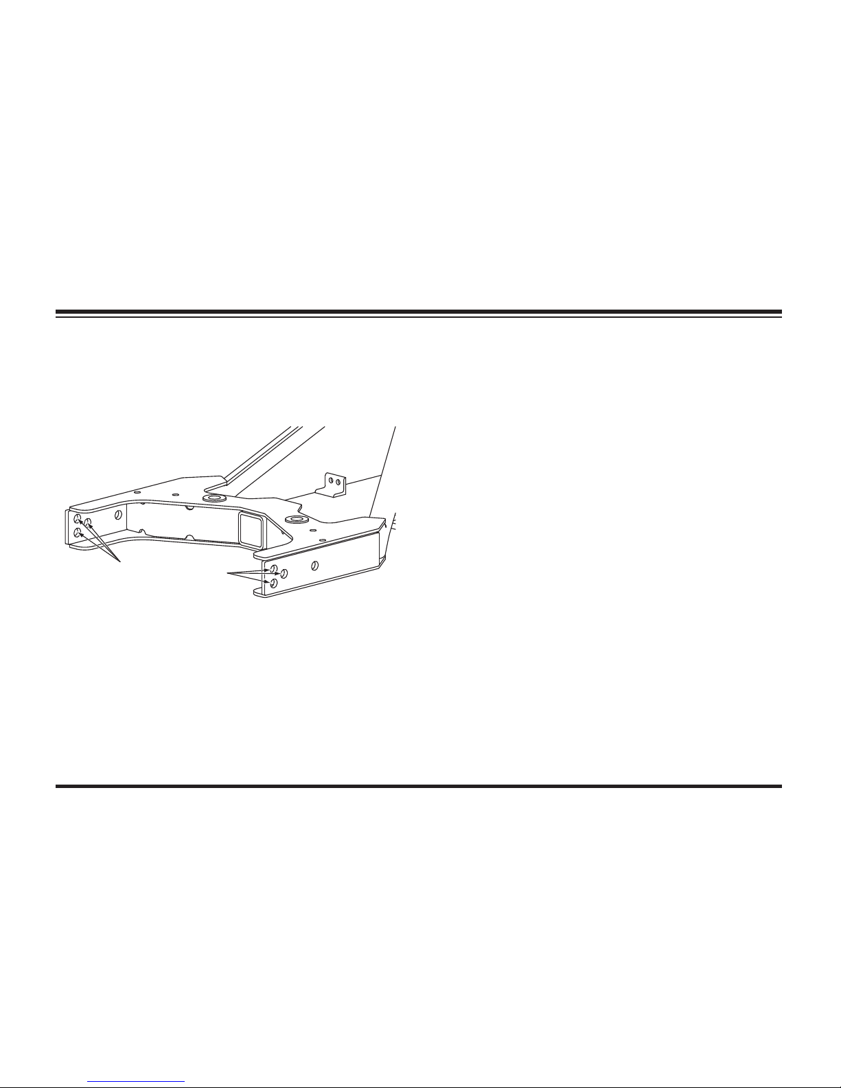
Lit. No. 49513, Rev. 00 88 August 15, 2011
MAINTENANCE
6. Select the hole in the rear of the T-frame that
is best aligned with the rear hole in the push
beam and reinstall the rear fasteners. Tighten
all four fasteners to 250 ft-lb.
7. Raise and lower the blade several times. The
cutting edge should be contacting the level
surface across the full length of the cutting
edge.
8. Verify that the cutting edges remain in full
contact with the ground while the wings
are shifted from the scoop position to the
retracted (vee) position. Reinstall blade shoes
if removed in Step 3.
Complete this procedure as often as required
to provide even cutting edge wear. Replace the
cutting edge(s) on your MVP PLUS™ blade when
worn to within 1" of the carriage bolts.
Select the hole
best aligned with
the rear holes in
the push assembly
Page 88
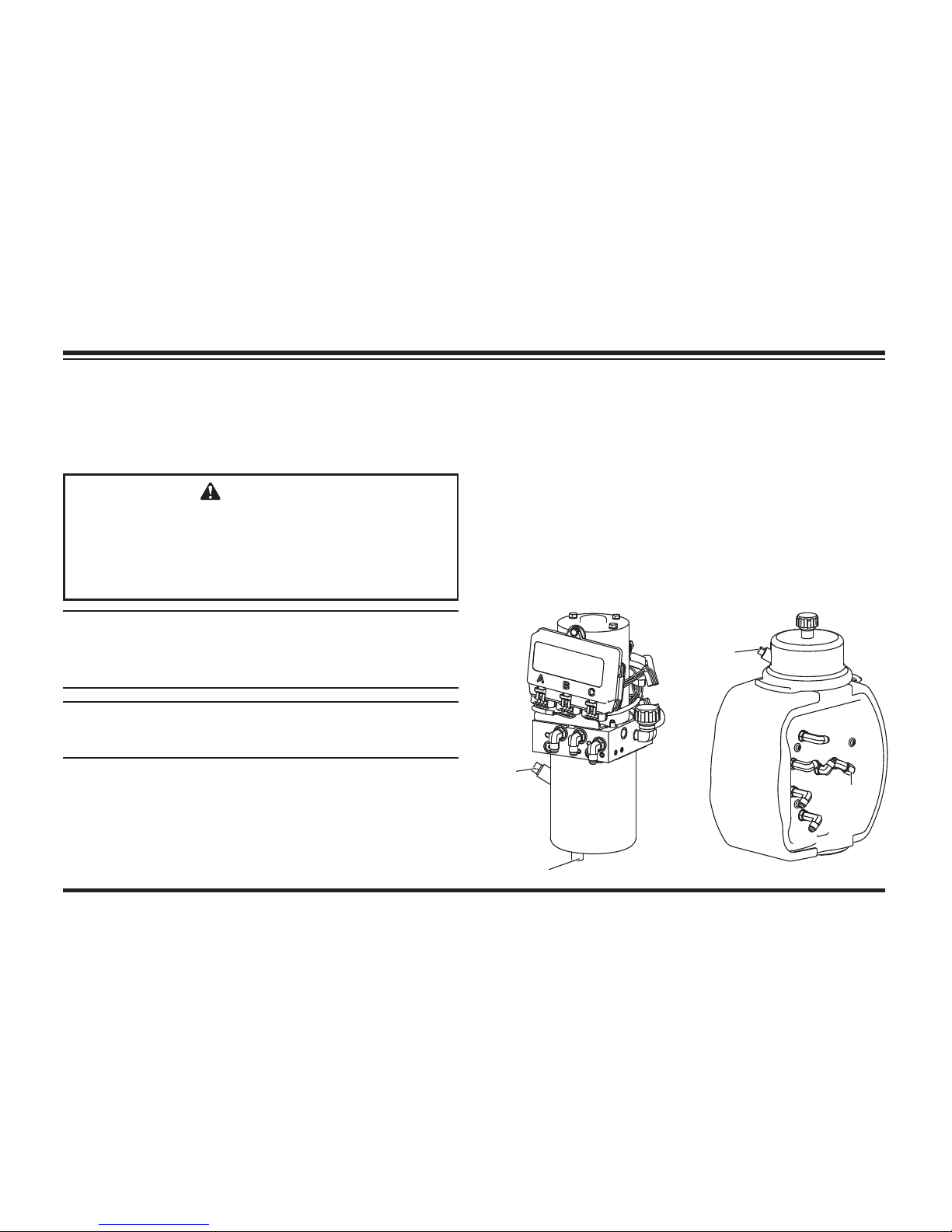
Lit. No. 49513, Rev. 00 89 August 15, 2011
HYDRAULIC SYSTEM
Fluid Level
NOTE: On MVP PLUS™ and WIDE-OUT™
blades, add fl uid only when all rams are
retracted.
NOTE: Remove fi ll plug slowly to relieve any
pressure in reservoir.
MAINTENANCE
1. With the UltraMount® 2 system attached to the
vehicle, activate the control.
2. For straight blades, any angle will do, but for
MVP PLUS and WIDE-OUT blades, move
blade wings to fully retracted (vee) position.
3. Activate the control FLOAT function and
manually collapse the lift ram all the way.
Fill
Plug
Drain
Plug
Straight Blades MVP PLUS Blades
Fill
Plug
Drain
Cap
CAUTION
Do not mix different kinds of hydraulic
fl uid. Some fl uids are not compatible and
may cause performance problems and
product damage.
Page 89
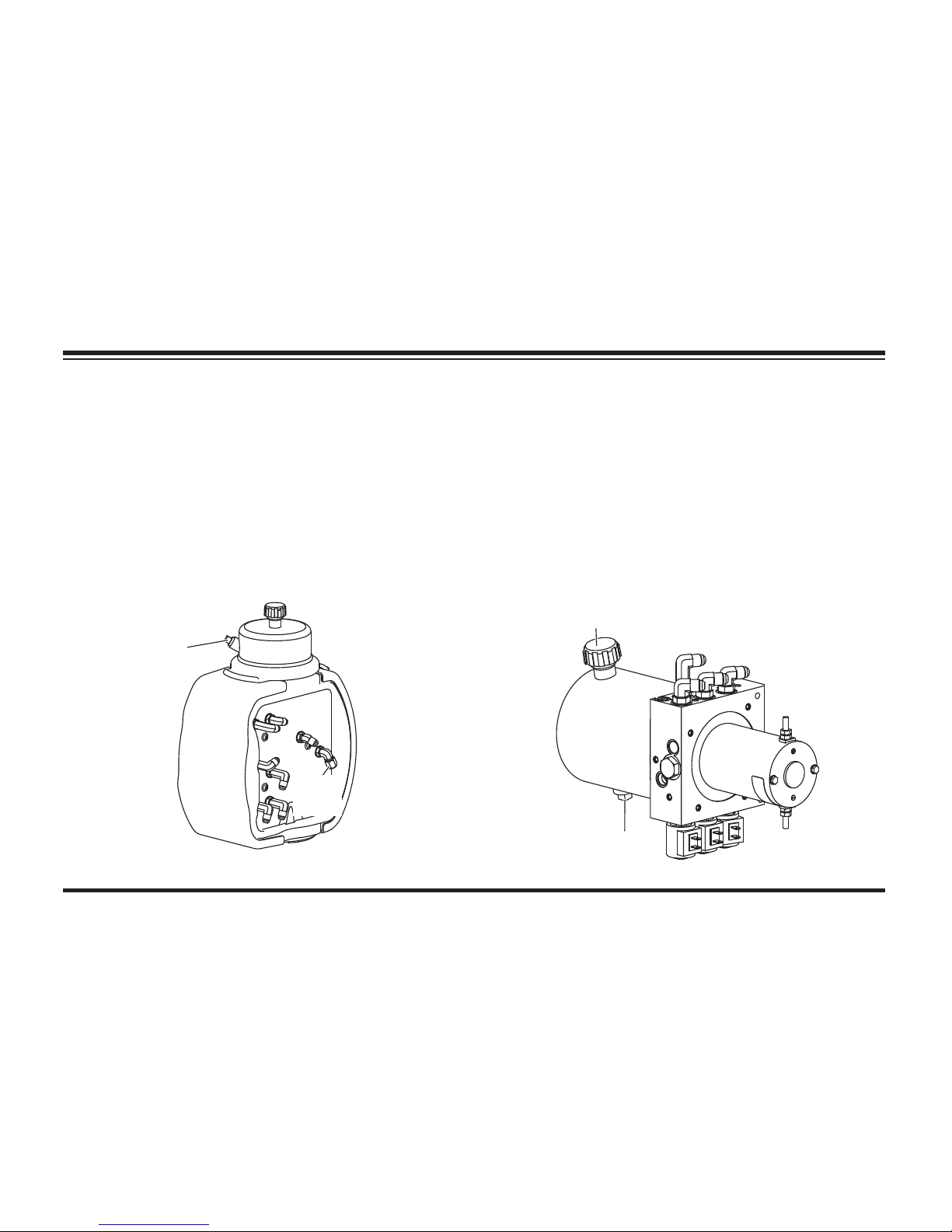
Lit. No. 49513, Rev. 00 90 August 15, 2011
MAINTENANCE
Drain
Cap
WIDE-OUT™ Blades
Fill
Plug
4. Turn the control OFF.
5. Remove the fi ll plug.
6. HTS™ Blades: Fill the reservoir to within
2-1/2" from the top of the fi ll hole and replace
the fi ll plug.
HTS Blades
Drain
Plug
Breather/Fill Plug
MVP PLUS™, WIDE-OUT™ and other
Straight Blades: Fill the reservoir to the top
of the fi ll hole and replace the fi ll plug.
For fl uid recommendations see the following
"Annual Fluid Change" section.
Page 90

Lit. No. 49513, Rev. 00 91 August 15, 2011
Annual Fluid Change
1. Perform this operation with the snowplow
attached to the truck on a hard level surface.
2. Lower the blade to the ground.
3. Activate the control FLOAT function and
manually collapse the lift ram all the way (not
required for HTS™ blades). Turn the control
OFF.
MAINTENANCE
4. HTS Blades and Straight Blades: Remove
the hydraulic unit cover as described in the
Blade Drop Speed Adjustment procedure in
the Operating Your Snowplow section.
NOTE: Loosen fi ll plug slowly to relieve any
pressure in the reservoir.
5. Remove the drain plug located in the bottom
of the hydraulic reservoir for straight blades,
or the drain cap located on the fi tting side
of the hydraulic unit for MVP PLUS™ and
WIDE-OUT™ snowplows. (See illustrations on
the previous page.)
6. Completely drain the reservoir and replace the
drain plug/cap.
7. Carefully note hose routing and positions of any
protective hose wraps for proper reassembly.
8. Remove the angle ram hoses from the fi ttings
on the hydraulic unit and place in a drain pan
or suitable container. (See the following
CAUTION
Do not mix different kinds of hydraulic
fl uid. Some fl uids are not compatible and
may cause performance problems and
product damage.
CAUTION
Change the fl uid at the beginning of each
plowing season. Failure to do this could
result in condensation buildup during the
non-plowing season.
Page 91
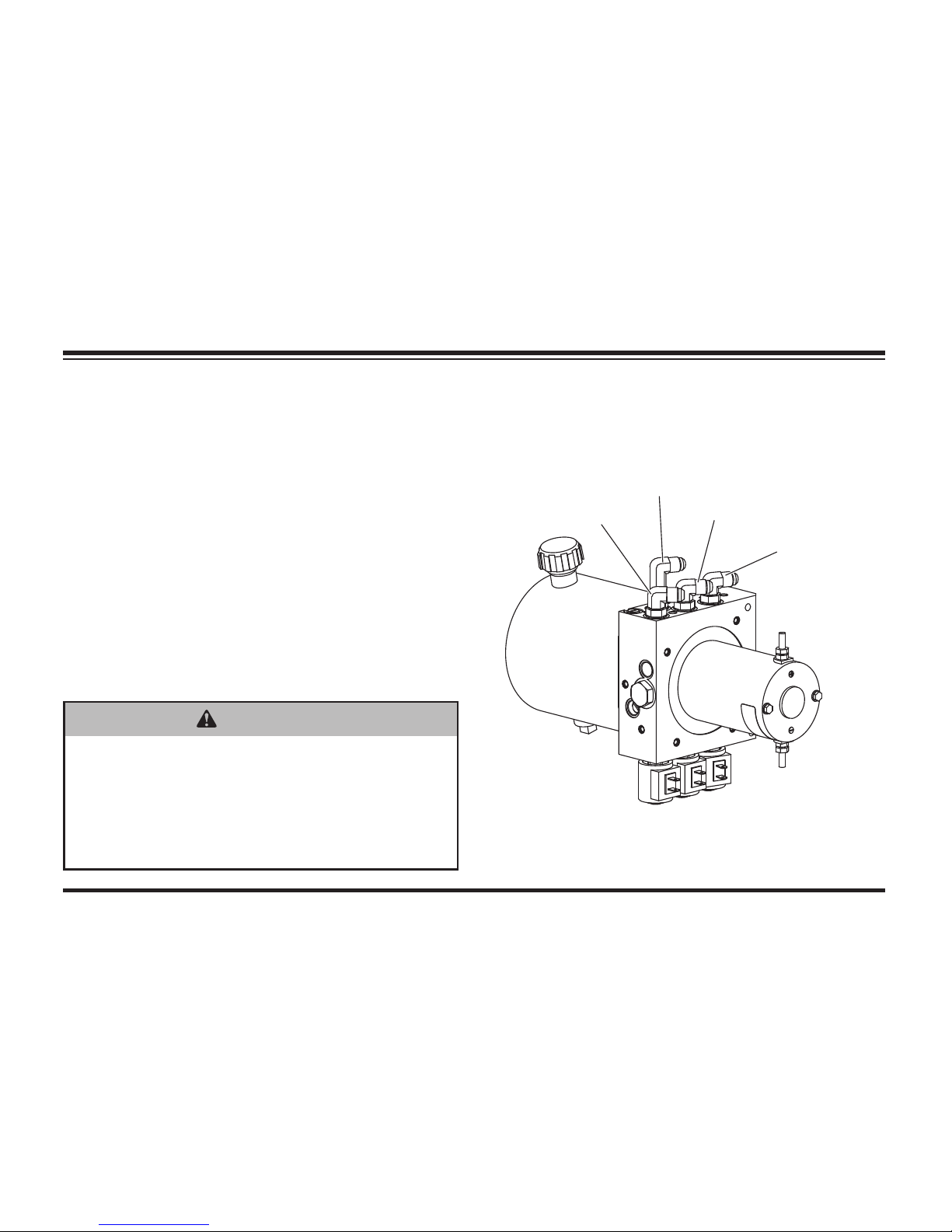
Lit. No. 49513, Rev. 00 92 August 15, 2011
Hose Routing for HTS™ Blades
To PS
Angle Ram
To DS
Angle Ram
To Lif t
Ram Base
To Lif t
Ram Rod
illustrations and Hydraulic Hose or Fitting
Replacement instructions.)
9. Manually angle the blade fully in each direction
to remove fl uid from the angle rams. Do not
allow the hose(s) from the extending ram or
the opposite side of the ram (MVP PLUS™
blades only) to take fl uid back in.
10. Reconnect the angle ram hoses to the proper
fi ttings. Reinstall all protective hose wraps in
their original positions. (See the following
illustrations for your snowplow type and
Hydraulic Hose or Fitting Replacement
instructions.)
MAINTENANCE
WARNING
Keep 8' clear of the blade drop zone when
it is being raised, lowered or angled. Do
not stand between the vehicle and blade
or directly in front of blade. If the blade
hits you or drops on you, you could be
seriously injured.
Page 92
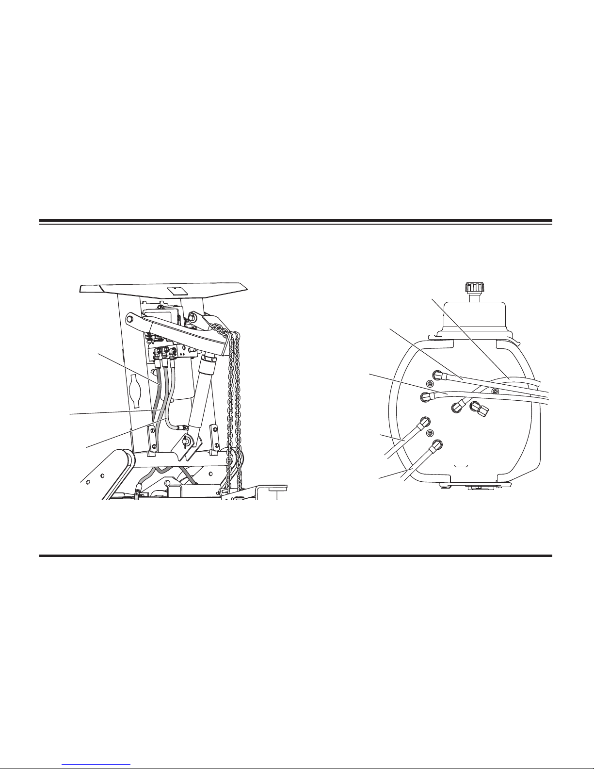
Lit. No. 49513, Rev. 00 93 August 15, 2011
MAINTENANCE
Hose Routing for MVP PLUS™ Blades
To PS R od
(Front)
To DS B ase
(Rear)
To PS B ase
(Rear)
To Lif t R am
To DS R od
(Front)
Hose Routing for Straight Blades
Driver-Side
Hose
Passenger-Side
Hose
Lift Ram
Hose
Page 93
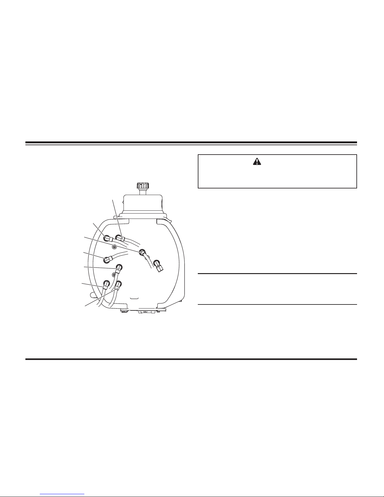
Lit. No. 49513, Rev. 00 94 August 15, 2011
Hose Routing for WIDE-OUT™ Blades
To PS W ing
Rod (inside)
To DS Angle Ram
To PS Angle Ram
To DS W in g
Base (outside)
To DS W in g
Rod (inside)
To PS W ing
Base (outside)
To Lif t R am
11. For straight blades, any angle will do, but
MVP PLUS and WIDE-OUT blades must
be in the fully retracted (vee) position. With
the lift ram fully retracted, fi ll the reservoir
with WESTERN® High Performance
Hydraulic Fluid to –40°F (–40°C), or other
fl uid conforming to Military Specifi cation
MIL-H-5606A, such as Mobil Aero HFA or
Shell AeroShell® Fluid 4. Replace the fi ll plug.
NOTE: On MVP PLUS™ and WIDE-OUT™
blades, add fl uid only when all rams are
retracted.
MAINTENANCE
AeroShell® is a registered (®) trademark of Shell Oil Company.
CAUTION
Do not raise blade during fi ll process as
this may cause pump cavitation.
Page 94

Lit. No. 49513, Rev. 00 95 August 15, 2011
MAINTENANCE
Air Removal – HTS™ & Straight Blades
11. Turn the control ON and completely angle
blade to the left and right several times. Turn
the control OFF.
12. Fill the reservoir to the top of the fi ll hole and
replace the fi ll plug.
NOTE: Loosen fi ll plug slowly to relieve any
pressure in the reservoir.
13. Turn the control ON and raise and lower the
snowplow several times. Activate the control
FLOAT function and manually collapse the
lift ram all the way after each lowering of the
blade. Turn the control OFF.
14. Fill the reservoir to the top of the fi ll hole and
replace the fi ll plug.
HTS™ blades: Fill to within 2-1/2" from the
top of the fi ll hole and replace the plug.
WARNING
To prevent accidental movement of
the blade, always turn the control OFF
whenever the snowplow is not in use. The
power indicator light will turn OFF.
Page 95
Lit. No. 49513, Rev. 00 96 August 15, 2011
MAINTENANCE
Air Removal – MVP PLUS™ Blades
11. Turn the control ON and completely extend
and retract the driver-side wing several times.
With all rams fully retracted, turn the control
OFF.
12. Fill the reservoir to the top of the fi ll hole and
replace the fi ll plug.
NOTE: Loosen fi ll plug slowly to relieve any
pressure in the reservoir.
13. Repeat Steps 11 and 12 for the passengerside wing.
14. Turn the control ON and raise and lower the
snowplow several times. Activate the control
FLOAT function and manually collapse the
lift ram all the way after each lowering of the
blade. With all rams fully retracted, turn the
control OFF.
15. Fill the reservoir to the top of the fi ll hole and
replace the fi ll plug.
WARNING
To prevent accidental movement of
the blade, always turn the control OFF
whenever the snowplow is not in use. The
power indicator light will turn OFF.
Page 96
Lit. No. 49513, Rev. 00 97 August 15, 2011
MAINTENANCE
Air Removal – WIDE-OUT™ Blades
11. Turn the control ON and completely extend
and retract the driver-side wing several times.
Repeat for the passenger-side wing. With
the wing and lift rams fully retracted, turn the
control OFF.
12. Fill the reservoir to the top of the fi ll hole and
replace the fi ll plug.
NOTE: Loosen fi ll plug slowly to relieve any
pressure in the reservoir.
13. Turn the control ON. Angle blade fully left
and right and raise and lower the snowplow
several times. Activate the control FLOAT
function and manually collapse the lift ram all
the way after each lowering of the blade. With
all rams fully retracted, turn the control OFF.
14. Fill the reservoir to the top of the fi ll hole and
replace the fi ll plug.
WARNING
To prevent accidental movement of
the blade, always turn the control OFF
whenever the snowplow is not in use. The
power indicator light will turn OFF.
Page 97

Lit. No. 49513, Rev. 00 98 August 15, 2011
Hose or Fitting Replacement
DO NOT use thread sealant/tape on hoses
or fi ttings. This could damage product. Follow
recommended replacement procedures for fi ttings
and hoses.
1. Lower the snowplow completely, and turn the
control OFF.
NOTE: Loosen fi ll plug slowly to relieve any
pressure in the reservoir.
MAINTENANCE
2. Carefully note hose routing and positions
of any protective hose wraps for proper
reassembly.
3. Loosen hoses or fi ttings slowly to relieve any
residual pressure.
4. To remove a hose, loosen and unscrew the
hose fl are nut from the fi tting.
5. To remove a fi tting, loosen the jam nut and
unscrew the fi tting from the port.
Procedure for Installing Hydraulic
Fittings and Hoses
NOTE: Overtorquing JIC hose fi tting ends will
result in a fractured fi tting.
DO NOT use any type of sealant or tape on the
fi ttings or hoses. This could damage product.
Always use two wrenches to ensure proper
tightening of fi ttings and hoses.
WARNING
Lower blade when vehicle is parked. Keep
8' clear of blade drop zone. Temperature
changes could change hydraulic pressure,
causing the blade to drop unexpectedly or
damaging hydraulic components. Failure
to do this could result in serious personal
injury.
Page 98

Lit. No. 49513, Rev. 00 99 August 15, 2011
MAINTENANCE
Use the following procedure to install SAE
O-ring fi ttings in valve block and rams:
1. Turn the jam nut on the fi tting as far back as
possible.
2. Lubricate the O-ring with clean hydraulic fl uid.
3. Screw the fi tting into the port by hand until the
washer contacts the port face and shoulder of
the jam nut threads.
4. Unscrew the fi tting to the proper position no
more than one full turn.
5. Using two wrenches, hold the fi tting body
in position and tighten the jam nut until the
washer again contacts the port face, then
tighten an additional 1/8–1/4 turn to lock the
fi tting in place. Final torque on the jam nut
should be approximately 20 ft-lb.
Use the following procedure to install
hydraulic hoses:
1. Screw the fl are nut onto the fi tting fl are and
hand tighten.
2. Align the hose so there are no twists or sharp
bends and so it will not be pinched or pulled
by moving parts.
3. Using two wrenches, hold the hose in position
and tighten the fl are nut 1/8–1/4 turn beyond
hand tight. Final torque on the fl are nut should
be approximately 20 ft-lb.
4. Reinstall any protective hose wraps in their
original positions.
Page 99

Lit. No. 49513, Rev. 00 100 August 15, 2011
MAINTENANCE
FUSE REPLACEMENT
The vehicle control harness contains two
automotive blade-style fuses. The snowplow
park/turn power and control power are covered
by individual 10-amp fuses. The control fuse is
"hot" when the vehicle ignition switch is ON and
the electrical connections to the snowplow are
completed.
See the Harness Diagram at the end of this
manual for fuse locations.
The MVP PLUS™ hydraulic unit harness system
contains four automotive blade-style mini fuses.
The 3-solenoid harness (to Port B on the hydraulic
unit module) and 8-solenoid harness (to Port C)
each contain two 4-amp mini fuses.
The WIDE-OUT™ hydraulic unit harness system
contains four automotive blade-style mini fuses.
The 2-solenoid harness (to Port B on the hydraulic
unit module) and 6-solenoid harness (to Port C)
each contain two 4-amp mini fuses.
The straight blade and HTS™ hydraulic unit
harness systems contain two 4-amp automotive
blade-style mini fuses in the 3-solenoid harness
(to Port B on the hydraulic unit module).
If a problem should occur and fuse replacement
is necessary, the replacement fuse must be of the
same type and amperage rating as the original.
Installing a fuse with a higher rating can damage
the system and could start a fi re.
VEHICLE
The snowplow operating vehicle shall be
maintained according to manufacturer's
recommendations. Tire pressure shall be
maintained according to manufacturer's
recommendation.
Page 100

Lit. No. 49513, Rev. 00 101 August 15, 2011
MAINTENANCE
RECYCLE
When your snowplow has performed its useful life,
the majority of its components can be recycled
as steel or aluminum. Hydraulic fl uid shall be
disposed according to local regulations. Balance
of parts made of plastic shall be disposed of in a
customary manner.
BLADE FINISH
If the powder-coated fi nish is nicked or scratched,
repair the blade surface with WESTERN® red
or black paint in aerosol or quart can from your
WESTERN outlet. Clean and repaint parts as
necessary.
EMERGENCY PARTS/TOOLS
We suggest that you keep a WESTERN
Emergency Parts Kit (PN 67880 for straight
blades, PN 69600 for HTS™ blades, PN 44796-1
for MVP PLUS™ blades and PN 50687 for
WIDE-OUT™ blades) in your vehicle. These
kits contain WESTERN hydraulic fl uid, dielectric
grease, common hoses, pins, clips, fasteners and
a motor relay.
Also keep the following items in your vehicle for
emergency use:
• 10" Adjustable Wrench
• Pair of Pliers
• Medium Screwdriver
• Miscellaneous Fasteners
Always use WESTERN designed and tested
replacement parts.
 Loading...