

Page 1
Interface converter
between terminal equipment
(RS-232 or RS-422/485)
and the SecureStream™ 300 network
INSTALLATION MANUAL
6606-2201
www.westermo.se
TD-300
©
Westermo Teleindustri AB • 1999 • REV. A
Galvanic
Isolation
Transient
Protection
Balanced
TransmissionCEApproved
RS-232
RS-422/485
Page 2

2 6606-2201
Modem description
Introduction
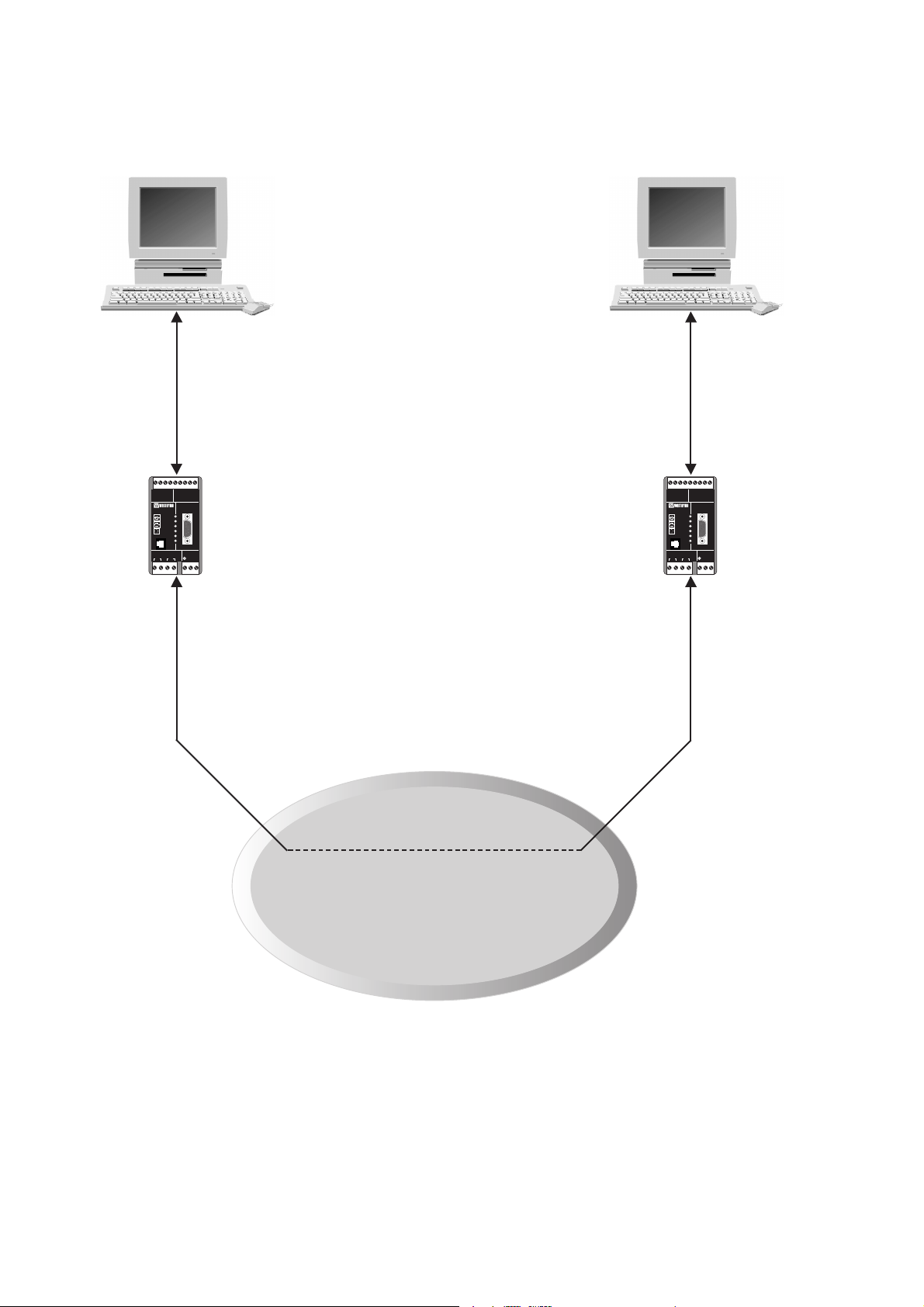
TD-300 is an interface converter for connecting terminal equipment to British TelecomÕs
SecureStreamª 300 network. The SecureStreamª 300 network functions as a Virtual
Private Data Network using proven digital technology of British TelcomÕs UK National
Telex network at a data rate of 300 bit/sec. The service offers a transparent connection
between customer terminals. The SecureStreamª 300 is available anywhere in the UK.
The DTE connection on TD-300 can handle either RS-232 or RS-422/485 (one at a
time). It is possible to communicate with different data rates on the DTE (300, 1200,
2 400 or 9 600 bit/sec) and the line connection (300 bit/sec) due to the fact that the interface converter includes a microprocessor and data buffers.
TD-300 supports three types of connections via the SecureStreamª 300 network:
¥ Fixed Point to Point connection
¥ Fixed Destination Call (Hot Line)
¥ Variable Destination Call
The unit can be configured to different running conditions via DIP switches.
Fixed Point To Point connection
A Fixed Point To Point connection implies that the TD-300 units establishes
a permanent connection via the SecureStreamª 300 network. This also implies that one
of the TD-300 units is the master unit which will establish the condition to the other
TD-300 unit which is set in slave mode.
In this running mode:
¥ The interface converters initiate a call at power up. Retries will be made
until a connection is established.
¥ The connection will not be cleared unless there is a failure.
¥ One modem (the originating modem) must be configured as ÓFixed masterÓ
and the other modem (the answering modem) must be configured as ÓFixed slaveÓ.
¥ DCD is activated as long as a connection is maintained.
¥ CTS is activated as long as a connection is maintained and the buffers
are not filled up (<80% of maximum buffer).
¥ DSR is always activated.
Page 3

36606-2201
Fixed Destination Call (Hot Line)
A Fixed Destination Call implies that the SecureStreamª 300 network always routes all
calls to a single fixed destination. The TD-300 can be configured to initiate a Fixed
Destination Call either by the DTE equipment sending data or activating RTS.
The TD-300 buffers all received data from the DTE equipment until a connection is
established.
The call is cleared either when the RTS on the calling TD-300 is deactivated or if no data
has been send or received for the last 5 seconds. Note that only the calling TD-300 may
clear the call.
In this running mode:
¥ The interface converter connect / disconnect the line with active /
inactive data or RTS
¥ The modems must be configured as "Hot line"
¥ DCD is activated as long as the connection is maintained.
¥ CTS is always activated when connected with active data
¥ CTS is activated as long as the connection is maintained and the buffers
are not filled up (<80% of maximum buffer) when connected with active RTS.
¥ DSR is always activated.
Variable Destination Call (normal mode)
A variable destination call implies that the SecureStreamª 300 network routes the
incomming calls to an address specified in the calling sequence. In this mode the TD-300
units emulates a subset of the Hayes standard command set to set up and maintain the
connection. The basic Hayes commands are provided and also the possibility to connect to
a predefined address with data or active RTS. A possibility to use answerback is also
included.
In this running mode:
¥ The interface converters is controlled by Hayes commands.
¥ The modems must be configured as ÓNormalÓ.
¥ DCD and CTS are controlled by Hayes commands.
¥ No flow control, RTS/CTS flow control or XON/XOFF flowcontrol is possible.
¥ DSR is always active.
Page 4
4 6606-2201
TD-300
9
R+ R- T-T+
PWR
RD
TD
RTS
CTS
DCD
TX
876
RS-422/485 RS-232
LINE CONNECTION
LINE
POWER
V.24/RS-232-C
SG RD TD
543
CTS2RTS
1
RX N L
SecureStream™ 300
(Virtual Private Network)
RS-232 or
RS-422/485
V.21V.21
RS-232 or
RS-422/485
9
876
R+ R- T-T+
RS-422/485 RS-232
TD-300
PWR
CTS
LINE
DCD
LINE CONNECTION
TX
543
SG RD TD
V.24/RS-232-C
RD
TD
RTS
RX N L
1
CTS2RTS
POWER
Page 5

56606-2201
TD-300 Specifications
Transmission Asynchronous, full/half duplex or simplex
DTE interface EIA RS-232-C/CCITT V.24/V.28, 9-pin D-sub female or
9-pin detachable screw block (only signals SG, RD, TD,
RTS, CTS are available)
EIA RS-422/RS-485/CCITT V.11 detachable
9-pin screw block
Line interface CCITT V.21. 2-wire. 4 pin detachable screw block
Transmission speed DTE interface: 300, 1200, 2400 and 9600 bit/s
Line interface: 300 bit/s
Power supply 230V AC +15%/–10% 49–62 Hz, 12–36V DC
Fuse AC 100mA fast 5x20 mm, DC 1,6A
LED’s PWR, RD, TD, RTS, CTS, DCD
Power consumption AC 2VA, DC 1,5W
Temperature range 5–50°C
Humidity range 0–95% RH without condensation
Dimensions 55 x 100 x 128 (WxHxD)
Weight AC 0.5 kg. DC 0.3 kg
Mounting On 35 mm DIN-rail
Page 6
6 6606-2201
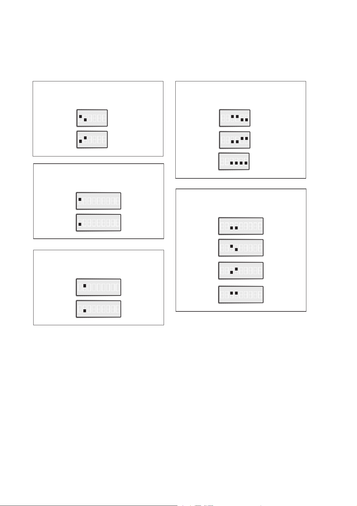
TD-300 Switch settings.
A 6 pole DIP switch provides the settings for the RS-485/422 interface. Via the 9 pole
DIP switch it’s possible to select different communication parameters for the DTE
connection and to configure the unit for different running modes.
2 or 4 wire
RS-422/485
S3 2-wire
S3 4-wire
Number of stop bits
(DTE connection)
S4 2
ON
123456789
S4 1
ON
123456789
Number of data bits
(DTE connection)
S4 7
ON
123456789
S4 8
ON
123456789
Parity
(DTE connection)
S4 No parity
ON
123456789
S4 Odd parity
ON
123456789
S4 Even parity
ON
123456789
S4 No parity
ON
123456789
ON
123456
ON
123456
Termination
RS-485/422
S3
Termination
2-wire (RS-485)
S3
Termination
4-wire (RS-422)
ON
123456
ON
123456
S3
No termination
ON
123456
Page 7

76606-2201
Data rate
(DTE)
S4 300 bit/s
ON
123456789
S4 1200 bit/s
ON
123456789
S4 2400 bit/s
ON
123456789
S4 9600 bit/s
ON
123456789
Running condition
via SecureStream™ 300
Factory settings
S4
Fixed master
ON
123456789
S4
Fixed slave
ON
123456789
S4
Hot line
ON
123456789
S4
Normal
ON
123456789
Running condition
via DTE in normal mode
S4
Quiet mode
ON
123456789
S4
Normal mode
ON
123456789
S4
ON
123456789
ON
123456
S3
Quiet mode implies that no result codes or
echo is sent to DTE, this is often used in a PLC
connection. Normal mode implies that the
result codes and echo to DTE is controlled by
commands.
Page 8

8 6606-2201
TD-300
9
R+ R- T-T+
PWR
RD
TD
RTS
CTS
DCD
TX
876
RS-422/485 RS-232
LINE CONNECTION
LINE
POWER
S3:1–6
V.24/RS-232-C
SG RD TD
543
CTS2RTS
1
RX N L
123456789
S4:1–9
Connections TD-300
RS-422/485 connection
(9-pole screw terminal)
Line connection
(4-pole screw terminal)
Direction
No.
Description
Receiver 9 A’ (R+)
Receiver 8 B’ (R–)
Transmitter 7* A (T+)
Transmitter 6* B (T–)
5 Shield
Direction
Pin no.
line
Description
Not used 3 R
Not used 4 R
Receiver/Transmitter 1 T
Receiver/Transmitter 2 T
*) Two wire connection
The definations R+/R–, T+/T– can be
various between different manufactures.
Page 9

96606-2201
O 1 109 DCD/Data Carrier Detect
O 2 4 104 RD/Received Data
I 3 3 103 TD/Transmitted Data
NC 4
– 5 5 102 SG/Signal Ground
O 6 107 DSR/Data Set Ready
I 7 1 105 RTS/Request to Send
O 8 2 106 CTS/Clear to Send
NC 9
Signal description
Terminal connection (DTE)
(RS-232-C/V.24, 9-pole D-sub, female alt. 9-pole screw terminal)
Direction
Pin
no.
Screw-
terminal
CCITT V.24
Description
N 115V*/230V
L AC power
PE/Protective Earth
Power connection (AC)
(3-pole screw terminal)
*) TD-300 115V
No.
Power
supply
1 – Voltage
2 + Voltage
Connection
no.
Power
supply
Switch settings
According to TD-300 AC
Connections
According to TD-300 AC, except power supply
TD-300 DC
I = input O = output NC = not connected
Page 10

10 6606-2201
DTE Command lines
A command line is a string of characters send from a DTE to the modem (DCE) while the
modem is in a command state. A command line has a prefix, a body, and a terminator. Each
command line must begin with the character sequence AT and must be terminated by a carriage return. Commands entered in upper case or lower case are accepted, but both the A
and T must be of the same case, i.e., ÓATÓ (ASCII 065, 084) or ÓatÓ = (ASCII 097, 116).
The body is a string of commands restricted to printable ASCII characters (032-126).
Space characters (ASCII 032) and control characters other than CR (ASCII 013) and BS
(ASCII 008) in the command string are ignored. The default terminator is the CR (ASCII
013) character. Characters that precede the AT prefix are ignored. The command line
interpretation begins upon receipt of the carriage return character.
Characters within the command line are parsed as commands with associated parameter
values. The basic commands consist of single ASCII characters, or single characters preceded by a prefix character (e.g., Ô&Õ or Ô%Õ), followed by a decimal parameter.
The modem supports the editing of command lines by recognizing a backspace or delay
character. When modem echo is enabled, the modem responds to receipt of a backspace or
delete by echoing a backspace character, a space character, and another backspace. A command line may be aborted at anytime by entering < ctrl-x > (ASCII 024).
The AT sequence may be followed by any number of commands in sequence, except for
commands such as Z, D, O or H. Commands following Z, D, O or H on the same command line will be ignored. The maximum number of characters on any command line is
39 (including 'A' and 'T'). If a syntax error is found anywhere in a command line command, the remainder of the line will be ignored and the ERROR result code will be
returned to the DTE.
Commands entered with parameters out of range will not be accepted and the ERROR
result code will be returned to the DTE. Commands will only be accepted by the modem
once the previous command has been fully executed, which is normally indicated by the
return of an appropriate result code. Execution of command D will be aborted if another
characters is received from DTE before completion of the handshake.
When the modem has established a connection and has entered on-line data mode, it is
possible to break into the data transmission in order to issue further commands to the
modem in an on-line command mode. This is achieved by the DTE sending to the modem
a sequence of three ASCII characters specified by register S2. The default character is '+'.
The timing of the three characters must comply with specific time constraints. There is a
guard time before the first character and a guard time following the third character and
also between each character. This guard-time is set to one second in all cases. If other
characters are received within the guard time the escape sequence is not recognized.
Page 11

116606-2201
AT command set
The modem will respond to the commands detailed below. Parameters applicable to each
command are listed with the command description.
&Bn Ð RTS Dial Option
This command stores the current profile and enables or disables the dialing with active
RTS from DTE. The modem will dial the address stored with AT&Z0=.....
&B0 Disable dial with active RTS signal.
&B1 Enable dial with active RTS signal.
Observe that this will take the modem to RTS-mode and an active RTS from DTE will be interpreted
as a dial command. There are three possibilities to leave RTS-mode.
Number one is to use the (&B0) command with RTS inactivated.
Number two is to use the escape sequence when the modem is connected and then disable the dial
with RTS (&B0).
Another possibility is to remove the D-sub or the RS-232 screw block (inactivate RTS) and repower
the modem and then use switch S4:8 which works as a reset switch and will disable the dial with
active RTS-signal (&B0).
The modem will be reset on a ON to OFF to ON sequence on switch S4:8.
Switch S4:8 can only be used when the modem is disconnected from the line.
&Cn Ð DCD Option
This command controls the DCD signal.
&C0 DCD active at all times.
&C1 DCD active when a connection is established (default).
Dn Ð Dial Option
This command directs the modem to establish a connection. If no dial string is supplied
the modem will established a Hot Line call (if available).
The valid dial string parameters are described below.
0-9 digits 0-9
En Ð Command Echo
This command enables or disables the echo of characters to the DTE.
E0 Disables command echo.
E1 Enable command echo (default).
Page 12

12 6606-2201
&En Ð Data Dial Options
This command stores the current profile and enables or disables the dialling with data
from DTE. The modem will dial the address stored with AT&Z0=....
&E0 Disable dial with data.
&E1 Enable dial with data.
Observe that this will take the modem to data-mode and all incoming characters from DTE will be
interpreted as a dial command. There are two possibilities to leave data mode.
Number one is to use the escape sequence when the modem is connected and then disable the dial
with data (&E0).
Another possibility is to use switch S4:8 which works as a reset switch and will disable the dial with
data (&E0). The modem will be reset on a ON to OFF to ON sequence on switch S4:8.
Switch S4:8 can only be used when the modem is disconnected from the line.
&F Ð Recall (restore) factory configuration
This command restores the original factory setting of all parameters and S-registers.
When the modem is restarted the parameter set by the customer will be restored.
By using the &W command the factory setting will be valid also after restart of the
modem.
H Ð Disconnect (hang up)
This command initiates a hang up sequence.
&Kn Ð Flow control
This command defines the DTE/DCE (terminal/modem) flow control mechanism.
&K0 Disables flow control (default).
&K3 RTS/CTS flow control.
&K4 XON/XOFF flow control (with characters specified in S-register 32 and 33).
O Ð Return to On-Line Data Mode
This command returns the modem to data mode when the modem has entered the on-line
command mode. Observe that this command is only possible when a connection is established and the escape sequence has been entered.
Qn Ð Result Codes Control
This command enables or disables the result codes to the DTE.
Q0 Enables result codes to DTE (default).
Q1 Disables result codes to DTE.
Page 13

136606-2201
Sn=x Ð Write to S-register
This command write a value x to specified S-register n. See S-register section for specification of S-registers. Observe that a value x out of range will generate an error.
%Sn Ð Answerback
This command enables or disables the answerback function. Also observe the
stored/expected answerback strings with &Zn command.
%S0 Disable answerback (default).
%S2 Enable answerback.
Vn Ð Result Code Form
This command selects the short or long-form for the resultcodes.
V0 Enables short-form (terse) result codes. Line feed is not issued before a short-
form result code.
V1 Enables long-form (verbose) result codes (default).
&V Ð Display Current Configuration and Stored Profile
The modem reports the current and the stored profile, the stored number for data / RTS
connection and stored / expected answerback.
Example:
ACTIVE PROFILE:
E1 Q0 V1 X1 &B0 &C1 &E0 &K0 %S0
S02:043 S03:013 S04:010 S30:100 S32:017 S33:019 S98:010 S99:000
STORED PROFILE:
E1 Q0 V1 X1 &B0 &C0 &E0 &K3 %S0
S02:043 S03:013 S04:010 S30:100 S32:049 S33:048 S98:050 S99:100
STORED NUMBER FOR DATA/RTS CONTROL:
123456
STORED ANSWERBACK:
WESTERMO
EXPECTED ANSWERBACK:
WESTERMO
&W Ð Store Current Configuration
This command saves the current (active) configuration (profile), including S-registers. The
stored setting is restored by using the Z command.
Page 14

14 6606-2201
Xn Ð Result Codes Response Set:
This command selects which subset of the result messages that will be used by the
modem to inform the DTE of the results of the commands.
X0 Basic response set. Send only result codes OK, CONNECT, RING,
NO CARRIER, ERROR and NO ANSWER to DTE.
X1 Extended response set. Send result codes as above and also NO DIALTONE,
BUSY and NO ANSWER to DTE (default).
Z Ð Soft reset and Restore Profile
This command performs a soft reset and restores the stored profile.
&Zn=x Ð Store numbers and answerback
This command stores a string x which specifies the address for dialing with data/RTS,
the expected answerback or the stored answerback.
&Z0=... Number for dialling with data/RTS
&Z1=... Store answerback string in modem. This string will be sent when answerback
is active. Observe that only ASCII characters 33 up to 126 are possible to use
in the string.
&Z2=... Expected answerback string. This string will be searched for in a connection
when answerback mode is active. Observe that only ASCII characters 33 up to
126 are possible to use in the string.
Page 15

156606-2201
Result codes
When a command is sent from the DTE the modem replies with a result code. The result
code may be either in Long Form i.e. text (V1) or in Short Form i.e. a digit code (V0).
The result code in Long Form is followed by <CR><LF> and in Short Form by <CR>.
The result codes are enabled by using the Q1 command.
The possible result codes are as follows:
With basic response set (X0)
0 OK Command accepted and executed.
1 CONNECT A call has entered the connect phase.
2 RING Incoming call detected.
3 NO CARRIER Ended call (correct or incorrect) or no carrier.
4 ERROR Illegal command / command not possible
With extended response set (X1) as above and:
6 NO DIALTONE No carrier or error code DER from network
7 BUSY Error codes NC or OCC from network
8 NO ANSWER Error codes NA, NP, NCH or ABS from network
Page 16

16 6606-2201
S-registers
The section belows describes the available S-registers.
The S-registers are set by using the Sn=x command. The registers are stored by using
the &W command.
S2 Ð Escape character
S2 holds the decimal value of the ASCII character used as the escape character. The
default value corresponds to Õ+Õ(ASCII 043). Possible values are 0-255 and a value over
127 will disable the escape process.
S3 Ð Carriage Return Character
S3 hold the decimal value of the ASCII character used as command line and result code
terminator. The default value corresponds to <CR> (ASCII 013). Possible values are 0-127.
S4 Ð Line Feed Character
S4 hold the decimal value of the ASCII character used as line feed. The default value corresponds to <LF> (ASCII 010). Possible values are 0-127.
S30 Ð Disconnect Inactivity Timer
S30 holds the value of the length of time in tenths of seconds that the modem will stay
on-line before disconnecting when no data is sent or received. Observe that this command
is only valid when &E1 command (datamode). The default value is 0 (disabled) and possible values are 0-255 (0-25,5 seconds). The default value 0 implies that the modem will
not disconnect the line with the inactivity timer.
S32 Ð XON Character
S32 holds the decimal value of the ASCII character used as XON character. The default
value corresponds to <DC1> (ASCII 017). Possible values are 0-255.
S33 Ð XOFF Character
S33 holds the decimal value of the ASCII character used as XOFF character. The default
value corresponds to <DC3> (ASCII 019). Possible values are 0-255.
S98 Ð Packet size
S98 holds the packet size value. Using this register will make it possible to package incoming signs from V.21 side and send on DTE side when the packed size parameter is reached.
The default value correspond to 0 which will disable the register. Possible values are 0Ð255
which corresponds to a packet size between 0Ð255 signs. See also register S99.
S99 Ð Delay timer
S99 holds the delay timer value. Using this register with register S98 will make it possible
to send signs even if the packet size value is not reached. If no signs are received on the
V.21 side within the specified delay timer value the signs that are buffered will be sent on
the DTE side. The default value corresponds to 0 wich will disable the register. Possible
values are 0Ð255 which corresponds to a timer value between 0Ð255 ms. See also register
S98.
Page 17

176606-2201
Examples
Example 1 Ð AT commands
Several commands can be stacked on each command-line. For example
ATE0Q1X0D1235
can be used instead of
ATE0
OK
ATQ1
OK
ATX0
OK
ATD1235
Example 2 Ð Frequently used settings for PLC-systems
Most PLC-systems and other industrial applications require the same changes to the standard settings.
The most commonly encountered problems concern speed, format and control signals
from the connected equipment.
Speed and format are changed with the switches under the cover in block SW4.
SW4:9 can be used to set the modem in quiet mode which will disable echoing and result
codes to the DTE.
Other problems might concern control signals to the connected equipment. Below follows
a list of commands that might resolve the problems. For further information regarding
these commands please refer to the specific section of this manual.
AT&C1 Control DCD signal.
AT&K0 Flow control modem/terminal
Page 18

18 6606-2201
Example 3 Ð Dial up with data from DTE
Dial-up can be made by sending data from DTE. A typical application might be an unintelligent equipment at the DTE side, e.g. an alarm.
The modem must be set up with the address to dial with
ATZ0=..... (up to 20 digits).
The inactivity timer must be assigned to allow the modem to disconnect after a predefined
period with no data in either direction.
ATS30=..... (0-255 equals 0-25,5 seconds)
The modem must be set up with the AT&E1 command allowing the modem to use datamode. This will also store the current profile and on the next incoming data from the DTE
side the modem will connect to the predefined address. The modem is equipped with a
redial function which will make further connection attempts if the first connection fails.
Page 19

196606-2201
OWN COMMENTS
.....................................................................................................................................................................................................................
.....................................................................................................................................................................................................................
.....................................................................................................................................................................................................................
.....................................................................................................................................................................................................................
.....................................................................................................................................................................................................................
.....................................................................................................................................................................................................................
.....................................................................................................................................................................................................................
.....................................................................................................................................................................................................................
.....................................................................................................................................................................................................................
.....................................................................................................................................................................................................................
.....................................................................................................................................................................................................................
.....................................................................................................................................................................................................................
.....................................................................................................................................................................................................................
.....................................................................................................................................................................................................................
.....................................................................................................................................................................................................................
Page 20

6606-2201 10.99 Mälartryck AB, Eskilstuna, Sweden
Westermo Teleindustri AB • S-640 40 Stora Sundby, Sweden
Phone +46 16 612 00 Fax +46 16 611 80
E-mail: info@westermo.se • Westermo Web site: www.westermo.se
Westermo Teleindustri AB have distributors in several countries,
contact us for further information.
Westermo Data Communications GmbH
Bruchsaler Straße 18, 68753 Waghäusel
Tel.: +49(0)7254-95400-0 • Fax.:+49(0)7254-95400-9
E-Mail: westermo.germany@t-online.de
Westermo Data Communications Ltd
Solent Business Centre • Millbrook Road West
Millbrook, Southampton • SO15 0HW
Phone: +44(0)2380 704 611 • Fax.:+44(0)2380 702 682
E-Mail: sales@westermo.co.uk
Subsidiaries
Block diagram
Data
buffer
OR
Settings
0V
0V
DSR RTS CTS DCD RD TD RD TD
Data
buffer
FSK
modulation
Data rate
conversion
(if needed)
Data rate
conversion
(if needed)
FSK
demodulation
Analogue filtering
FSK modulated data (V21) for connection
to the “Secure Stream™ 30” network
Line interface
DTE
interface
RS-232 RS-422/485
Modem
chip
Processor,
UART and
memory
 Loading...