

Page 1

AT Commands
Reference Guide
6618-3202
TDW-33
TD-36, TD-36 485
TR-36, TR-36B
4
3
2
1
4
3
2
1
©
Westermo Teleindustri AB
Industrial Telephone Modem
www.westermo.com
Page 2
Introduction
1
2
3
5
4
This document describes the AT-commands that can be used to configure and control the
TDW-33, TD-36, TD 36 485 and TR-36 modem.
AT Commands
Responses
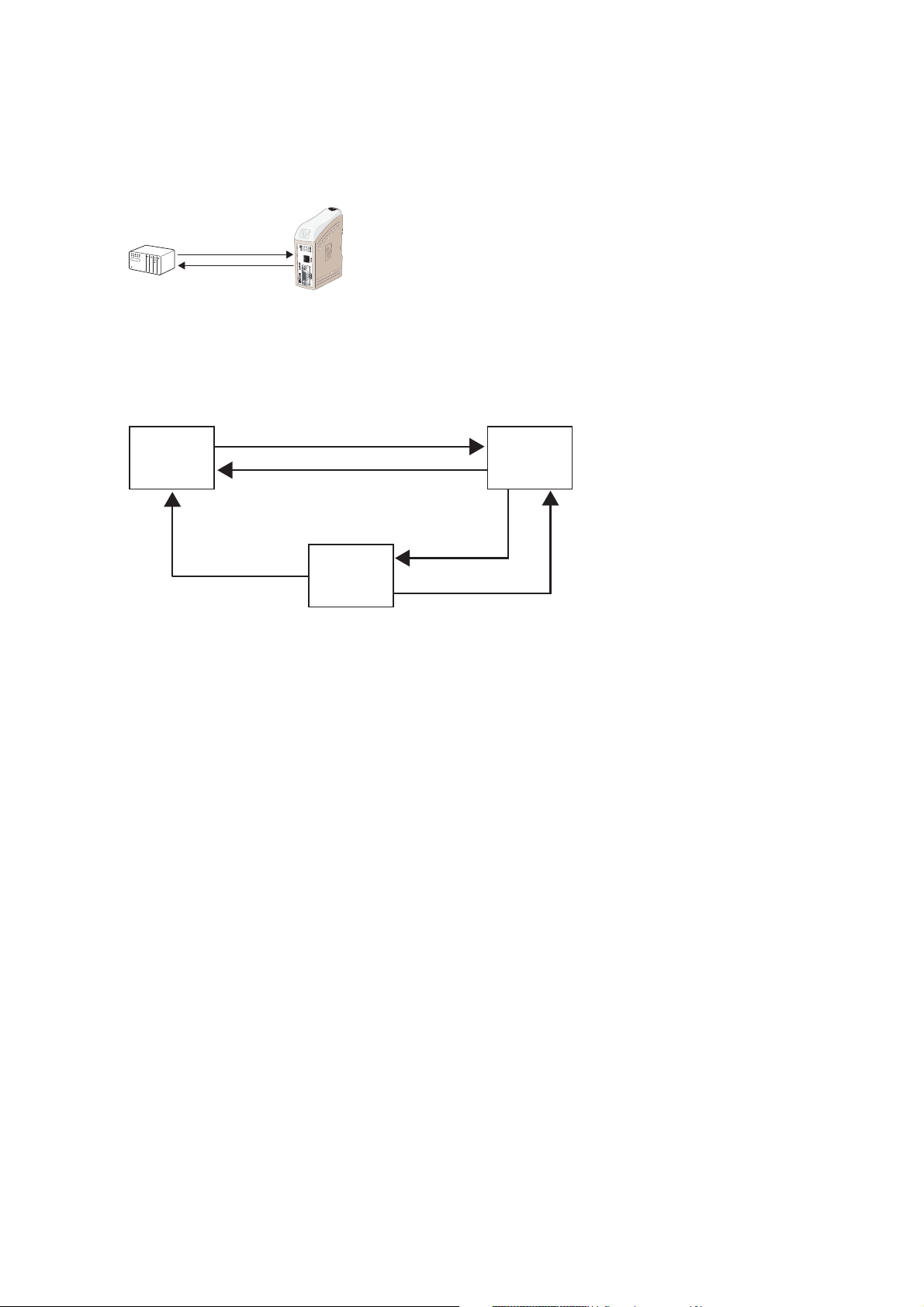
The TDW-33, TD-36, TD-36 485 and TR-36 different operating modes are controlled by
AT-commands.
Modem operation modes:
Command
Mode
Online
Command
Mode
Online
Mode
Example of commands/events that can trigger a change of the modems operation modes
1 – ATD command
2 – Hangup from the remote end
3 – Escape sequence +++
4 – ATO command
5 – ATH command
For more information about Westermo, please visit out websit
22
e www.westermo.com.
6618-3202
Page 3

Abbreviations and definitions
Abbreviations
ASCII American Standard Code for Information Interchange
AT ATtention; this two-character abbreviation is always used to start a command line to
be sent from TE to Modem
BCD Binary Coded Decimal
ETSI European Telecommunications Standards Institute
IRA International Reference Alphabet (ITU-T T.50 [13])
ISO International Standards Organisation
ITU-T International Telecommunication Union – Telecommunications Standardization Sector
TE Terminal Equipment, e.g. a computer (equal to DTE; Data Terminal Equipment)
TIA Telecommunications Industry Association
Definitions
<CR> Carriage return character, which value is specified with command S3.
<LF> Linefeed character, which value is specified with command S4.
<...> Name enclosed in angle brackets is a syntactical element.
Brackets themselves do not appear in the command line.
[...] Optional subparameter of a command or an optional part of ME information
response is enclosed in square brackets. Brackets themselves do not appear in the
command line. When subparameter is not given in parameter type commands, new
value equals to its previous value. In action type commands, action should be done on
the basis of the recommended default setting of the subparameter
underline Underlined defined subparameter value is the recommended default setting of this
subparameter. In parameter type commands, this value should be used in factory
settings that are configured by V.25ter command &F0. In action type commands, this
value should be used when subparameter is not given.
6618-3202
33
Page 4

List of AT-commands
Commands always start with AT (which means ATtention) and finish with a <CR>
character.
Information responses and result codes
Responses normally start and end with <CR><LF>, except when the modem is set to
“short result code format” with the command ATV0, or when the ATQ1 (no result
codes) command is used.
If command syntax is incorrect, an ERROR string is returned. If extended error result
codes are configured (+CMEE) and if command syntax is correct but with some incorrect parameters, the +CME ERROR: <Err> or +CMS ERROR: <SmsErr> strings are
returned with different error codes. If the command line has been performed successfully,
an OK string is returned. In some cases, such as “AT+CPIN?” or (unsolicited) incoming
events, the product does not return the OK string as a response. In the AT-command list
below, <CR> and <CR><LF> are intentionally omitted.
Special AT-commands
In addition to the commands listed below there are two special commands that do not
start with AT.The first command is “A/” without any <CR>.This command makes the
modem repeat the last entered command.The second special command is the “+++”
(also without <CR>).This command is called “escape sequence” and is used when the
modem is in dedicated mode (online mode).When entering “+++” in dedicated mode,
the modem will switch from “online mode” to “online command mode”.This means that
it is possible to send commands to the local modem.The escape sequence is useful when
disconnecting the active call.The disconnection is made with the ATH command (see the
list of AT-commands below).The ATO command can also be used when in “online command mode”.
4
6618-3202
Page 5

General commands
The AT command line accepts up to 65 characters.
A – Answer a call
Supported by:
TDW-33 TD-36 TD-36 485 TR-36 TR-36B
Description:
The modem will go off-hook and attempt to answer an incoming call if correct conditions are met. Upon successful completion of answer handshake, the modem will go online in answer mode.
A successful negotiation must be met during time set by register S7
Syntax:
ATA
Parameters:
No parameters
Command example Possible responses Note
ATA CONNECT<speed> Answer to this incoming
call, call accepted
S register: S7 sets time allowed to connect
&An – Dial Abort Option
Supported by:
Description:
The modem normally aborts the option the connection negotiation if a character is
received from DTE during the connection phase. This command gives the user the
option to let the modem ignore characters.
Syntax:
&A<n>
Parameters:
<n>
0: Enables Abort (Default)
1: Disable Abort
Command example Possible responses Note
AT&A<n> OK The command is valid
TDW-33 TD-36 TD-36 485 TR-36 TR-36B
and accepted
ERROR Otherwise
S register: The value is written to S14 bit 4
6618-3202
5
Page 6

Bn – ITU-T or BELL
Supported by:
TDW-33 TD-36 TD-36 485 TR-36 TR-36B
Description:
When the modem is configured to allow either option, the modem willl select Bell or
ITU-T modulation for a line speed connection of 300 or 1200 bit/s. Any other line speed
will use a ITU-T modulation standard.
Syntax:
B<n>
Parameters:
<n>
0: Selects ITU-T Modulation (Default)
1: Selects Bell Modulation
Command example Possible responses Note
ATB<n> OK The command is valid
and accepted
ERROR Otherwise
S register: The value is written to S27 bit 6
\Bn – Transmit Break to Remote
Supported by:
Description:
In non-error correction mode, the modem will transmit a break signal to to the remote
modem with a length in multiples of 100 ms according to parameter specified.
The command works in conjunction with the \K command.
Syntax:
\B<n>
Parameters:
<n>
Corresponds to the break length in 100 ms units (Default = 3).
Command example Possible responses Note
AT\B<n> OK The command is valid
TDW-33 TD-36 TD-36 485 TR-36 TR-36B
and accepted
ERROR Otherwise
S register: None
6
6618-3202
Page 7

&Bn – DTR/TX Dial Option
Supported by:
TDW-33 TD-36 TD-36 485 TR-36 TR-36B
Description:
This command enables the modem to dial a number which is stored with AT&Z0
commands. This is performed when the DTR signal goes from inactive to active signal
level or when data is received on the DTE TX line (in command mode).
After enabling the Hotcall functionality the modem must be restarted for the function to
take affect. Disable the TX Hotcall function by sending an escape sequence ’+++’ to enter
command mode and then set the &Bn command. See also AT&D and AT&K
Syntax:
&B<n>
Parameters:
<n>
0: Disable DTR/TX Hotcall ( Default )
1: Enable DTR Hotcall
2: Enable TX Hotcall (buffered data)
Command example Possible responses Note
AT&B<n> OK The command is valid
and accepted
ERROR Otherwise
S register: S210 bit 5 and 6
Cn – Carrier control
Supported by:
Description:
This command is included for compatibility only, and has no effect other than returning
a result code.
Syntax:
ATC<n>
Parameters:
<n>
TDW-33 TD-36 TD-36 485 TR-36 TR-36B
Command example Possible responses Note
ATC<n> OK The command is valid and
accepted
ERROR Otherwise
S register: None
6618-3202
7
Page 8

%Cn – Select data compression
Supported by:
TDW-33 TD-36 TD-36 485 TR-36 TR-36B
Description:
This command enables or disables data compression. The modem can only perform data
compression on an error corrected link. The parameter value, if valid, is written to S41
bit 0 and 1.
Syntax:
AT%C<n>
Parameters:
<n>
0: No compression. Resets S46 bit 1.
1: Enables MNP 5 data compression. Resets S46 bit 1.
2: Enables V42bis data compression. Sets S46 bit 1
3: Enables both V.42bis and MNP5 data compression. Sets S46 bit 1. (Default)
Command example Possible responses Note
AT%C<n> OK The command is valid
and accepted
ERROR Otherwise
S register: The value is written to S41 bits 0 and 1 and S46 bit 1
&Cn – DCD Option
Supported by:
Description:
This command controls the DCD output in accordance with the parameter supplied
Syntax:
&C<n>
Parameters:
<n>
0: DCD remains ON at all times
1: DCD follows the state of a carrier (Default)
Command example Possible responses Note
AT&C<n> OK The command is valid
TDW-33 TD-36 TD-36 485 TR-36 TR-36B
and accepted
ERROR Otherwise
S register: The value is written to S21 bit 5
8
6618-3202
Page 9

D – Dial command
Supported by:
TDW-33 TD-36 TD-36 485 TR-36 TR-36B
Description:
The ATD command is used for data or fax call.
For a data or a fax call, the application sends the following ASCII string to the product:
ATD<nb> where <nb> represents a dial string composed of dial characters and
dial modifiers.
The dial characters include the decimal values 0 through 9, letters A,B,C,D, and the
symbols “*” and “#”.
Dial modifier description:
Separator Name Functionality
, Commaseparator Insert a pause in dialing procedure
$ Bongtonesepator A bong tone needs to be detected before
dialing continues
; Returncmdseparator Return to command state
/ waitsepator Waits for 0.125 seconds
: PABX Wait for PABX tone
+ Insert shortkey
? Delimiter Delimiter between number to be dialed (P#)
and PSTN security access password
W Wait Wait for dial tone before processing to next
character in the dial string
= Secdialsep. Wait for second dialtone
& Wait for credit card Wait for credit card dialing tone before
dialing tone continuing with the dial string. If the tone is
not detected within the time specified by S6
or S7, the modem will abort the rest of the
sequence, return on-hook, and generate an
error message.
@ Quietseparator Wait for second dialtone
L RE-dial The L must be immediately after the D with
last dialed number all characters ignored.
P Select pulse dialing Pulse dial the numbers that follow until a “T”
is encountered.
\ Select pulse dialing
T Select Tone dialing Pulse dial the numbers that follow until a “P”
is encountered.
S = n Dial Stored Number Dial the number stored in the directory
n = 0 to 3
! Flash The modem will go on-hook the time
specified in S29.
6618-3202
9
Page 10

^ Toggle call tone Applicable to current dial
enable/disable only
R This modifier needs to be
accepted, but not acted
on
() Ignored; may be used to
format dial string
- Ignored; may be used to
format dial string
<space> Ignored; may be used to
format dial string
<i> Ignored; may be used to
format dial string
Syntax:
ATD<nb>
Response:
The response to the ATD command is one of the following:
Result code Numeric result code Description
CONNECT <speed> Refer to description If the call succeeds, for
of result codes data calls only, <speed>
takes the value negotiated
by the product
NO CARRIER 3 Call setup failed or
remote user release
NO DIALTONE 6 Generate whenthe
modem does not detect
a valid dialtone during the
dial procedure
BUSY 7 If the called party is
already in communication
NO ANSWER 8 If no hang up is detected
after a fixed network
time-out
Parameters:
<nb> is the dial string
S register: None
10
6618-3202
Page 11

&Dn – DTR Control
Supported by:
TDW-33 TD-36 TD-36 485 TR-36 TR-36B
Description:
This commands controls the Data Terminal Ready (DTR) signal.
Syntax:
AT&D<n>
Parameters:
<n>
0: The DTR signal is ignored (Default)
1: Modem switches from data to command mode when DTR switches from ON
to OFF
2: Upon DTR switch from ON to OFF, the call is hang up
3: DTR drop causes the modem to perfom a soft reset.
Command example Possible responses Note
AT&D<n> OK The command is valid
and accepted
ERROR Otherwise
S register: The value is written to S21 bits 3 and 4.
En – Echo
Supported by:
Description:
This command is used to determine whether the modem echoes characters received by
an external application (DTE) or not.
Syntax:
ATE<n>
Parameters:
<n>
0: Characters are not echoed
1: Characters are echoed (Default)
Command example Possible responses Note
TDW-33 TD-36 TD-36 485 TR-36 TR-36B
ATE<n> OK The command is valid
and accepted
ERROR Otherwise
S register: The value is written to S14 bit 1
6618-3202
11
Page 12

%En – Enable/Disable Line Quality Monitor and Auto-Retrain or
Fallback/Fall Forward
Supported by:
TDW-33 TD-36 TD-36 485 TR-36 TR-36B
Description:
Enable/disable Line quality Monitor and Auto-Retrain or Fall back/fall forward.
This command controls if the modem automatically monitors the line quality and
requests a retrain (%E1) or fall back when line quality is insufficient or a fall forward
when line quality is sufficient (%E2). Set S41 bits 2 and 6.
Syntax:
AT%E<n>
Parameters:
<n>
0: Disable Line Quality and auto-retrain
1: Enable Line Quality and auto-retrain
2: Enable Line Quality Monitor and Fallback/Fall Forward / (Default)
Command example Possible responses Note
AT%E<n> OK The command is valid
and accepted
ERROR Otherwise
S register: The value is written to S41 bits 2 and 6.
12
6618-3202
Page 13

Fn – Select Line Modulation
Supported by:
TDW-33 TD-36 TD-36 485 TR-36 TR-36B
This command selects which type of modulation will be used on the phone line. If this
parameter is set to something other than F0, the line speed will be fixed.
(See also the +MS command)
Syntax:
ATF<n>
Parameters:
<n>
0: Selects Auto V8 automatically line speed according to the preference of the remote
modem. (Default)
1: Selects 300 bit/s, V.21 (if B0 is set) or Bell 103 (if B1 is set).
2: Selects V.22 600 bit/s
3: Selects V.23 , see %Fn for speed.
4: Selects V.22 (if B0 is set) or Bell 212A (if B1 is set). 1 200 bit/s.
5: Selects V.22bis,.2 400 bit/s,
6: Selects V.32bis 4 800 bit/s or V.32 4 800 bit/s.
7: Selects V.32bis 7 200 bit/s.
8: Selects V.32bis 9 600 bit/s or V.32. 9 600 bit/s.
9 : Selects V.32bis 12 000 bit/s.
10: Selects V.32bis 14 400 bit/s.
14: Selects V.34
15: Auto
Command example Possible responses Note
ATF<n> OK The command is valid
and accepted
ERROR Otherwise
6618-3202
13
Page 14

%Fn –V23 Speed selection
Supported by:
TDW-33 TD-36 TD-36 485 TR-36 TR-36B
The direction and speed of forward and backchannels for V23C modulation are set with
this command.
Syntax:
AT%F<n>
Parameters:
<n>
1: Selects 75Tx/1200Rx
2: Selects 1200Tx/75Rx
3: Selects 1200Tx/1200Rx. (Default)
Command example Possible responses Note
AT%F<n> OK The command is valid
and accepted
ERROR Otherwise
&Fn – Restore Factory Configuration
Supported by:
Description:
The modem loads factory default configuration (profile).
A configuration (profile) consists of a subset of S-registers.
Syntax:
AT&F<n>
Parameters:
<n>
0: Load factory default settings for all commands except Westermo specific commands.
1: Load factory default settings for all commands except Westermo specific commands.
2: Load factory default for Westermo specific commands.
Command example Possible responses Note
AT&F<n> OK The command is valid
TDW-33 TD-36 TD-36 485 TR-36 TR-36B
and accepted
ERROR Otherwise
S register: None
14
6618-3202
Page 15

+FCLASS – Select Active Service Class
Supported by:
TDW-33 TD-36 TD-36 485 TR-36 TR-36B
Description:
This command selects the active service class
Syntax
+FCLASS=<n>
+FCLASS?
+FCLASS=?
Parameters
<n>
0: Select Data Mode (Default.)
1: Select Facsimile Class 1
8: Select Voice Mode
Command example Possible responses Note
AT+FCLASS<n> OK The command is valid
and accepted
ERROR Otherwise
S register: None
&Gn – Select Guard Tone
Supported by:
Description:
The modem Generates the guard tone selected by this command according to the
parameter supplied (DPSK modulation modes only).
Syntax:
&G<n>
Parameters:
<n>
0: Disables Guard Tone (Default)
1: Disables Guard Tone
2: Selects 1800 Hz Guard Tone.
TDW-33 TD-36 TD-36 485 TR-36 TR-36B
Command example Possible responses Note
AT&G<n> OK The command is valid
and accepted
ERROR Otherwise
S register: The value is written to S23 bits 6 and 7.
6618-3202
15
Page 16

*Gn – Password control
Supported by:
TDW-33 TD-36 TD-36 485 TR-36 TR-36B
Description:
This command controls whether or not the modem will handle Password and/or Call
back functionality.
For compatibility reasons only. See also AT*WCB
Syntax:
*G<n>
Parameters:
<n>
0: Disables Password Control ( Default ), corresponds to AT*WCB = 0
1: Enables Password Control, corresponds to AT*WCB = 3
Command example Possible responses Note
AT*G<n> OK The command is valid
and accepted
ERROR Otherwise
S register: The value is written to S14 bit 6.
16
6618-3202
Page 17

+GCI – Country Parameters
Supported by:
TDW-33 TD-36 TD-36 485 TR-36 TR-36B
Description:
This command selects the country code for modem.
Syntax:
AT+GCI = <value>
AT+GCI = ?
AT+GCI?
Parameters:
<Value>
Please refer to Country table
i.e.
A5: Selects country code for Sweden
B5: Selects country code for America
C7: Universal country code (Default)
Command example Possible responses Note
AT+GCI = <value> OK The command is valid
and accepted
ERROR Otherwise
S register: None
Hn – Disconnect (Hang-Up)
Supported by:
Description:
This command initiates a hang-up sequence.
Syntax:
ATH<n>
Parameters:
<n>
0: The modem will release the line if the modem currently is on-line.
1: If on-hook, the modem will go off-hook and enter command mode.
TDW-33 TD-36 TD-36 485 TR-36 TR-36B
Command example Possible responses Note
ATH<n> OK The command is valid
and accepted
ERROR Otherwise
S register: None
6618-3202
17
Page 18

In – Request identification information
Supported by:
TDW-33 TD-36 TD-36 485 TR-36 TR-36B
Description:
This command causes the product to transmit one or more lines of specific information
text.
Syntax:
ATI<n>
Parameters:
<n>
0: Display max line speed.
1: Reserved
2: Reserved
3: Reserved
4: Display manufacturer identification.
5: Display country code.
6: Display revision identification for modem modulation code
7: Reserved
8: Display switch settings
9: Display Westermo Application Software revision identification.
Other values: “ERROR” string is sent back.
Command example Possible responses Note
ATI0 33600 Max line speed
OK
ATI4 WESTERMO Modem manufactor
TELEINDUSTRI AB identifier
OK
ATI6 BSMW310_BF533_bfbsmw310_5457OK Revision identification
OK for modem modula-
tion code
ATI8 000 000 000 000 Switch settings
OK Each DIP switch
displayed as a decimal
value. S1 S2 S3 S4
Notice switch setting
is only reed at powerup and ATZ
ATI9 4101-0201 Westermo SW
OK release
ERROR Otherwise
S register: None
18
6618-3202
Page 19

+ICF – Fixed DTE format
Supported by:
TDW-33 TD-36 TD-36 485 TR-36 TR-36B
Description:
This commands specifies the data format between the modem and the DTE.
Notice that format can’t be set with rate set to auto.
Syntax
AT+ICF = <format>
AT+ICF = ?
AT+ICF?
Parameters:
<format>
0 Auto
5,4 7NI
4,4 7N2
5,1 7E1
5,0 7O1
3,4 8N1
2,1 8E1
2,0 8O1
4,1 7E2
4,2 7O2
1,4 8N2
1,1 8E2
1,2 8O2
Command example Possible responses Note
AT+ICF? +ICF: (3,4)
OK Current format is 8N1
AT+ICF = ? +ICF(0-5),(0-4)
OK Allowed values
AT+ICF = (3,4) OK
AT+ICF = <n> ERROR If n is not valid
S register: None
6618-3202
19
Page 20

+IPR – Fixed DTE rate
Supported by:
TDW-33 TD-36 TD-36 485 TR-36 TR-36B
Description:
This commands specifies the data rate between the modem and the DTE.
Syntax
AT+IPR = <rate>
AT+IPR = ?
AT+IPR?
Parameters:
<rate>: baud rates that can be used by the DCE
0 (enables autobauding)
200
300
600
1200
2400
4800
9600
19200
38400
57600
115200
230400
Command example Possible responses Note
AT+IPR? +IPR: 9600
OK Current rate is 9600 bit/s
AT+IPR = ? +IPR: (0, 300, 600, 1200,
2400, 4800, 9600,
19200, 38400, 57600,
115200),
OK
AT+IPR = 38400 OK Disable autobauding and
set rate to 38400 bit/s
AT+IPR = 0 OK Enable autobauding
AT+IPR = n ERROR If n is not valid
S register: None
20
6618-3202
Page 21

\Kn – Break Control
Supported by:
TDW-33 TD-36 TD-36 485 TR-36 TR-36B
Description:
This command controls the response of the modem to a break signal received from the
terminal equipment, from the remote modem or through the \B command. The modem
can respond in three different ways depending on the state of the modem. The value is
written to S40 bit 3,4 and 5.
Syntax:
AT\K<n>
Parameters:
<n>
Mode 1
Modem is in on line data mode and a break is received from the DTE.
<n>
0: Enter on-line command modem, no break sent to the remote modem.
1: Clear data buffers and send break to remote modem.
2: Same as 0.
3: Send break to remote modem immediately.
4: Same as 0.
5: Send break to remote modem in sequence with transmitted data (Default).
Mode 2
Modem is in on line command mode and a \B is received in order send as a break to the
remote modem.
<n>
0: Clear data buffers, send break to the remote modem.
1: Same as 0.
2: Send break to remote modem immediately.
3: Same as 2.
4: Send break to remote modem in sequence with transmitted data.
5: Same as 4.
6618-3202
21
Page 22

Mode 3
A break is received from a remote modem during a non-error corrected connection.
<n>
0: Clear data buffers, send break to the DTE.
1: Same as 0.
2: Send break immediately to DTE.
3: Same as 2.
4: Send break to remote modem in sequence with transmitted data.
5: Same as 4. (Default)
Command example Possible responses Note
AT\K<n> OK The command is valid
and accepted
ERROR Otherwise
S register: The value is written to S40 bits 3, 4 and 5.
&Kn – DTE-DCE flow control
Supported by:
TDW-33 TD-36 TD-36 485 TR-36 TR-36B
Description:
This command controls the operation of local flow control between the DTE and DCE.
Syntax:
AT&K<n>
Parameters:
<n>
0: Disables Flow Control (Default)
3: Enables RTS/CTS
4: Enables XON/XOFF
Command example Possible responses Note
AT&K<n> OK <n>= 0 to 4
ERROR Otherwise
S register: The value is written to S39 bits 0, 1 and 2.
22
6618-3202
Page 23

Ln – Speaker Volume
Supported by:
TDW-33 TD-36 TD-36 485 TR-36 TR-36B
Description:
Sets the speaker volume control.
Syntax:
ATL<n>
Parameters:
L0: Low Volume
L1: Low Volume
L2: Medium Volume
L3: High Volume ( Default )
Command example Possible responses Note
ATL<n> OK
ERROR Otherwise
S register: The value is written to S22 bits 0 and 1.
%L – Report Line Signal Level
Supported by:
Description:
This command returns a value which indicates the received signal level.
Syntax:
AT%L
Parameters:
None
Command example Possible responses Note
AT&L 009
OK –9 dBm signal level
ERROR Otherwise
S register: None
TDW-33 TD-36 TD-36 485 TR-36 TR-36B
6618-3202
23
Page 24

*L – Display Stored Passwords and Callback numbers
Supported by:
TDW-33 TD-36 TD-36 485 TR-36 TR-36B
Description:
This command displays stored Password and Callback numbers.
Syntax:
AT*L
Parameters:
None
Command example Possible responses Note
AT*L 0 – Password, Callback number
1 – Password, Callback number
OK
ERROR Otherwise
S register: None
Mn – Speaker Control
Supported by:
TDW-33 TD-36 TD-36 485 TR-36 TR-36B
Description:
Speaker Control command.
Syntax:
ATM<n>
Parameters:
<n>
0: Speaker off
1: Speaker is on during call establishment, but off when receiving a carrier. (Default)
2: Speaker is always on
Same as 1 but only when answering, and not during call establishment.
3:
Command example Possible responses Note
ATM<n> OK
ERROR Otherwise
S register: The value is written to S22 bits 2 and 3.
24
6618-3202
Page 25

+MS – Select Modulation
Supported by:
TDW-33 TD-36 TD-36 485 TR-36 TR-36B
Description:
This command selects the modulation, enables or disables automode, specifies the
receive rates and specifies the transmit rates using six subparameters.
Syntax:
+MS = <carrier>,<automode>,<min_tx_rate>,<max_tx_rate>,<min_rx_rate>,<max_rx_
rate>
+MS = ?
+MS ?
Parameters:
<carrier>
V21 300 bit/s or 200 bit/s
V22 1200 bit/s
V22B 1200 or 2400 bit/s
V23C 75/1200, 1200/75 bit/s PSTN-mode dialled connections
V23HDX 1200/1200 half duplex PSTN dialled connections
(TD-36 and TD-36 485 also 2 wire leased line)
V23FDX 1200/1200 bit/s full duplex 4 wire leased line (only TD-36 485)
V32 4800 or 9600 bit/s
V32B 4800, 7200, 9600, 12000 or 14400 bit/s
V34 2400, 4800, 7200, 9600, 12000, 14400, 16800, 19200, 21600, 24000, 26400,
28800, 31200, 33600 bit/s
V34FC 2400, 4800, 7200, 9600, 12000, 14400, 16800, 19200, 21600, 24000, 26400,
28800, 31200, 33600 bit/s
V90A up to tx = 33600, rx = 56000 bit/s (client mode) Only TDW-33
V90D up to tx = 56000, rx = 33600 bit/s (server mode) Only TDW-33
B103 300 bit/s
B212 1200 bit/s
<automode>
0: Disable
1: Enable
<min_xx_rate>, <max_xx_rate>
Minimum and maximum data rate depending on modulation used.
Command example Possible responses Note
AT+MS = ? The modem sends a
string of information to
the DTE consisting of
supported options
AT+MS? List current configuration
S register: None
6618-3202
25
Page 26

\Nn – Select Operating mode
Supported by:
TDW-33 TD-36 TD-36 485 TR-36 TR-36B
Description:
This command controls the preferred error correcting mode for a data connection
Syntax:
AT\N<n>
Parameters:
<n>
0: Selects normal speed buffered mode (disables error-correction mode).
1: Selects direct mode and is equivalent to &M0, &Q0 mode of operation. In this
mode the serial port is directly connected to the data pump, which results in the
lowest possible delay time. This is useful in i.e. the case of polled PLC systems
where the response time is critical.
2: Selects reliable (error-correction) mode. The modem will first attempt a LAPM
connection and then an MNP connection. Failure to make a reliable connection
results in the modem hanging up.
3: Selects auto reliable mode. This operates the same as \N2 except failure to make a
reliable connection results in the modem falling back to the speed buffered normal
mode, \n0.
4: Selects LAPM error-correction mode. Failure to make an LAPM error-correctio
connection results in the modem hanging up. Note: The -K1 command overrides
the \n4 command.
5: Selects MNP error-correction mode. Failure to make an MNP error-correction
connection results in the modem hanging up.
Command example Possible responses Note
AT\N<n> OK
ERROR Otherwise
S register: The value is written to S36 and S48 (see description).
26
6618-3202
Page 27

On – Back to online mode
Supported by:
TDW-33 TD-36 TD-36 485 TR-36 TR-36B
Description:
If a connection has been established and the modem is in online command mode, this
command allows you to return to online data mode either with or without a retrain.
Syntax:
ATO<n>
Parameters:
<n>
0: Enters on-line mode without a retrain (Default).
1: Enters on-line mode with a retrain.
Command example Possible responses Note
ATO0 OK Enters on-line mode
without a retrain.
ATO1 OK Enters on-line mode with
a retrain
ERROR Otherwise or if not
connected
S register: None
6618-3202
27
Page 28

*Pn – Store Password and Callback numbers
Supported by:
TDW-33 TD-36 TD-36 485 TR-36 TR-36B
Description:
Used for storing password and callback number 0 and 1 for the secure callback function.
For compability reasons only. See also AT*WCBTAB
Syntax:
*P<n>:Password:Callbacknumber
Parameters:
<n>
0: Information for password 0 and callback number 0
1: Information for password 1 and callback number 1
Secure callback entry password must be none or 6-12 characters. secure callback entry
number can be 0-20 characters.
Command example Possible responses Note
*P0:password:callbacknumber OK
ERROR Otherwise
S register: None
Qn – Result Code Control
Supported by:
Description:
The Q command controls the issuing of result codes sent to acknowledge AT commands
and call status events (e.g. OK, ERROR, RING).
Syntax:
ATQ<n>
Parameters:
<n>
0: DCE transmits result codes (default)
1: Result codes are suppressed and not transmitted
Command example Possible responses Note
ATQ0 OK DCE transmits result
TDW-33 TD-36 TD-36 485 TR-36 TR-36B
codes
ATQ1 OK Result codes are
suppressed and not
transmitted
S register: The value is written to S14 bit 2.
28
6618-3202
Page 29

%Q – Report Line Signal Quality
Supported by:
TDW-33 TD-36 TD-36 485 TR-36 TR-36B
Description:
Command always respond with OK in on line command mode, ERROR will be sent on
all other cases.
For compability reasons only. See also AT&V1
Syntax:
AT%Q
Parameters:
None
Command example Possible responses Note
AT%Q OK
ERROR Otherwise
S register: None
&Qn – Asyncronous Mode
Supported by:
TDW-33 TD-36 TD-36 485 TR-36 TR-36B
Description:
This command is used to control connection modes permitted. It is used in conjunction
with S36 and S48.
See also AT\Nn.
Syntax:
AT&Q<n>
Parameters:
<n>
0: Selects direct asynchronous operation. The value 000b is written to S27 bits 3, 1,
and 0, respectively.
5: The modem will try to negotiate an error-corrected link. The modem can be con-
figured using S36 to determine whether a failure will result in the modem returning
on hook or will result in fallback to an asynchronous connection. The value 101b
is written to S27 bits 3, 1 and 0 respectively (Default).
6: Selects asynchronous operation in normal mode (speed buffering). The value 110b
is written to S27 bits 3, 1 and 0, respectively.
Command example Possible responses Note
AT&Q<n> OK
ERROR If not valid
S register: The value is written to S27 (see description).
6618-3202
29
Page 30

S – S-Register
Supported by:
TDW-33 TD-36 TD-36 485 TR-36 TR-36B
Description:
Sets and reads S registers.
Syntax:
ATS<value>[< = num>|<?>]
Parameters:
<value> Register
< = num> Set value number, 0-255
<?> Return register
Command example Possible responses Note
ATS0=2 OK Number value 0-255
ATS0? 2 / OK Number value 0-255
ERROR Register not valid or
number out of range
S register: None
&Sn – Set DSR signal
Supported by:
Description:
This commands controls the Data Set Ready (DSR) signal.
Syntax:
AT&S<n>
Parameters:
<n>
0: DSR always on
1: DSR off in command mode, DSR on in data mode
Command example Possible responses Note
AT&S0 OK DSR always on
AT&S1 OK DSR off in command
TDW-33 TD-36 TD-36 485 TR-36 TR-36B
mode, DSR on in data
mode
S register: The value is written to S21 bit 6.
30
6618-3202
Page 31

Vn – Result format
Supported by:
TDW-33 TD-36 TD-36 485 TR-36 TR-36B
Description:
This command selects the sending of short-form or long-form codes to the DTE.
Syntax:
ATV<n>
Parameters:
<n>
0 (Information responses): <text><CR><LF>
0 (Result codes): <numeric code><CR>
1 (Information responses): <CR><LF><text><CR><LF>
1 (Result codes): <CR><LF><verbose code><CR><LF>
Command example Possible responses Note
ATV0 0 DCE transmits limited
headers and trailers and
numeric result codes
ATV1 OK DCE transmits full
headers and trailers
and verbose response
text
S register: The value is written to S14 bit 3.
6618-3202
31
Page 32

\Vn – Single Line Connect Message
Supported by:
TDW-33 TD-36 TD-36 485 TR-36 TR-36B
Description
This command enables or disables the single line connect message.
This command override the ATWn command.
See also ATWn
Syntax:
AT\V<n>
Parameters:
<n>
0: Connect messages are controlled by the settings X, Y, and S95. (Default)
1: Connect messages are displayed in the single line format described below subject
to the command settings V (verbose) and Q (Quiet). In a non-verbose mode (V0),
single line connect messages are disabled and a single numeric result code is
generated for CONNECT DTE . The single line connect message format is:
Command example Possible responses Note
AT\V0 OK
AT\V1 OK
S register: None
32
6618-3202
Page 33

&Vn – Display Information
Supported by:
TDW-33 TD-36 TD-36 485 TR-36 TR-36B
Description
Displays information either of Current Configuration or last Connection Statistics
Syntax:
AT&V<n>
Parameters:
<n>
0: Display Current Configuration and Stored Profiles
1: Display present Connection Statistics
2: Display extended Connection Statistics
Command
example
AT&V0 ACTIVE PROFILE:
E1 M0 Q0 V1 W0 X4 &A1 &B0 &C1 &D0 &K0 &Q5 &S1 \N4 %F3
S00:001 S02:043 S03:013 S04:010 S05:008 S06:003 S07:075 S08:001 S09:000 S10:004
S11:000 S12:000 S22:112 S25:005 S30:000 S31:000 S40:040 S41:003 S46:002 S91:010
S95:000
Possible responses
STORED PROFILE 0:
E1 M0 Q0 V1 W0 X4 &A1 &B0 &C1 &D0 &K0 &Q5 &S1 \N4 %F3
S00:001 S02:043 S03:013 S04:010 S05:008 S06:003 S07:075 S08:001 S09:000 S10:004
S11:000 S12:000 S22:112 S25:005 S30:000 S31:000 S40:040 S41:003 S46:002 S91:010
S95:000
STORED PROFILE 1:
E1 M1 Q0 V1 W0 X4 &A1 &B0 &C1 &D2 &K0 &Q5 &S1 \N4 %F3
S00:001 S02:043 S03:013 S04:010 S05:008 S06:003 S07:075 S08:001 S09:000 S10:004
S11:000 S12:000 S22:116 S25:005 S30:000 S31:000 S40:040 S41:003 S46:002 S91:010
S95:000
TELEPHONE NUMBERS:
0 = 1 =
2 = 3 =
OK
6618-3202
33
Page 34

Command example Possible responses
AT&V1
Norm IDLE
Compression NONE
Protocol NONE
Speed Rx/Tx 0/0
Octets Sent/Rec 0/0
DataFrames Sent/Rec 0/0
ErrorFrames 0
ResentFrames 0
Frames Sent/Rec 0/0
CompressionEfficiency 100
ProtocolProgress 0
Disconnect Reason No disconnection
SNR 0 dB
RXLevel 0 dB
Echo Level 0 dB
Near Echo Level 0 dB
Far Echo Level 0 dB
Frequency Offset +0.0 Hz
Timing Offset 0
Line Voltage 0 V
Roundtrip Delay 0 ms
OK
S register: None
34
6618-3202
Page 35

+VRN – Ringback Never Appeared Timer
Supported by:
TDW-33 TD-36 TD-36 485 TR-36 TR-36B
Description:
This command sets the length of the time the modem will wait between ringbacks during
call originating before the modem can assume that the remote staion has gone off hook.
Syntax
+VRN=<n>
+VRN?
+VRN=?
Parameters
<n>
Decimal number 0 specifying the time period that the modem will wait for Ringback
during call origination.
A value of 0 forces the modem to report the OK result code. All other values give
ERROR as a result code.
S register: None
+VTS – Send Voice Tone(s)
Supported by:
Description:
This command causes the modem to send DTMF digits.
Syntax
+VTS=[<freq1>,<freq2>,<dur>]
+VTS=?
Parameters
freq1 (200-3000)
freq2 (200-3000)
dur (0-255)
S register: None
TDW-33 TD-36 TD-36 485 TR-36 TR-36B
6618-3202
35
Page 36

Wn – Connect message control
Supported by:
TDW-33 TD-36 TD-36 485 TR-36 TR-36B
Description:
This command controls the format of CONNECT message.
This command can be overide by ATS95 and AT\V commands.
Syntax:
ATW<n>
Parameters:
<n>
0: Upon connection, the modem reports only the DTE speed.
1: Upon connection, the modem reports the line speed, the error correction protocol,
and the DTE speed respectively.
2: Upon connection, the modem reports the DCE speed
Command example Possible responses Note
ATW OK <n> = 0,1,2
ERROR Otherwise
S register: The value is written to S31 bits 2 and 3.
&Wn – Store system setting
Supported by:
Description:
This command saves the current (active) configuration (profile), including S-Registers,
in one of the two user profiles as denoted by the parameter value.
Syntax:
AT&W<n>
Parameters:
<n>
0: Store the current configuration as profile 0
1: Store the current configuration as profile 1
Command example Possible responses Note
AT&W<n> OK Writes configuration
TDW-33 TD-36 TD-36 485 TR-36 TR-36B
<n> to EEPROM
S register: None
36
6618-3202
Page 37

*WACCTAB – Accepted numbers for A-number answering
Supported by:
TDW-33 TD-36 TD-36 485 TR-36 TR-36B
Description
The table can hold the numbers accepted for A-number answering. Up to 10 numbers
can be defined, all numbers defined will be compared to the incoming Caller ID when
A-number answer is enabled.
Syntax:
AT*WACCTAB = <entry>,<”num”>
AT*WACCTAB=?
AT*WACCTAB?
Parameters:
<entry>
Secure callback entry [1-10]
<”num”>
Accepted Caller ID [0-20 characters].
Command example Possible responses Note
AT* WACCTAB = 1,”12345” OK Set number (12345)
in entry 1
AT* WACCTAB = 2,”678” OK Set number (678)
in entry 2.
AT* WACCTAB = 2,”” OK Delete entry 2
AT* WACCTAB? OK List parameters
AT* WACCTAB = ? * WACCTAB : (0-10), List command parameters
(“0-20 CHAR”)
OK
ERROR Otherwise
S register: None
6618-3202
37
Page 38

*WCID – Caller ID / A-Number
Supported by:
TDW-33 TD-36 TD-36 485 TR-36 TR-36B
Description
This command set and display Caller ID parameters and data.
The modem supports different standards of CID (Caller Identification) which is set with
the mode parameter. Which standard used varies between countries and operators,
please check with your operator for correct mode.
The format parameter sets the way of presenting the CID/A-number. When A-number
detection is enabled there will be no presentation, but the modem will compare the CID
to the numbers stored in the WACCTAB. On a true compare the modem will answer
the call immediately. If the CID not compares to a number in the WACCTAB the normal
answering procedure controlled by S0 and ATA takes place.
Syntax:
AT*WCID = <format>,<mode>
AT*WCID = ?
AT*WCID?
Parameters:
<format>
0 Disables Caller ID /A-Number
1 Formated CID
2 Unformated CID
3 A-Number detection
<mode>
0 Between first and second ring
1 After detecting CAS
2 After line reversal
3 DTMF CID
Command example Possible responses Note
AT*WCID = 1,3 OK Selects DTMF Caller ID
with formated string presentation.
AT*WCID = 3,3 OK Selects A-Number detec-
tion based on DTMF CID
AT*WCID? *WCID: 1,3 Display current
OK *WCID settings
AT*WCID = ? *WCID: (0-3), (0-3) Display command
OK parameters
S register: None
38
6618-3202
Page 39

*WCB – Secure access and Callback
Supported by:
TDW-33 TD-36 TD-36 485 TR-36 TR-36B
Description
The secure callback functionality makes the established link more secure. After an incoming call the modem will make a callback to either a preconfigured number or to the
incoming number. The callback can be protected by a password. The unit can also be configured for a secure access without callback.
If the password is enabled, the calling part will be prompted for the password directly
after connection. When the password is entered correctly, the modem will disconnect
the current link and make a callback after a preset number of seconds WCBTIME.
If the unit is configured with password security, it will allow data only after the password
is correctly entered. After 3 retries of entering wrong password or after 60 seconds, the
link will be disconnected and the callback/secure access aborted.
Numbers and password used by the function is stored in the *wcbtab table
See also AT*WCBTAB.
Syntax:
AT*WCB = <n>
AT*WCB=?
AT*WCB?
Parameters:
<n>
0: Callback disabled (default)
1: Callback enabled, No password needed, callback number only in position 1
in *wcbtab (wcbtab1)
If “*wcbtab1” is empty no callback will be initiated.
2: Callback enabled, No password needed, callback to incoming number
No “RING” message will be sent to the local serial port at that time.
If the Caller ID is present the modem will callback to this number after the time of
WCBTIME.
When the connection is established CONNECT message will be sent to the DTE
interface.
Note that WCID must be enabled and set to the correct format for this function to
operate properly.
6618-3202
39
Page 40

3: Access security enabled, Password in one or more positions in WCBTAB<n>
(x = 1 -10). If a correct password is detected the connection is opened without any
callback.
The call request will be accepted silently. No “RING”and “CONNECT” message will
be sent to the local DTE interface at that time.
After a successful connection the answering modem will send the message:
“PASSWORD: “ to the originating side. Enter password and press return.
There will be three attempts given to enter the password correctly.
There is a fixed timeout of 60s to enter the password.
If the entered password is correct the modem will send message “RING” and
“CONNECT” to the DTE interface.
4: Callback enabled, Password and callback number in WCBTAB. The call request will
be accepted silently, no “RING”and “CONNECT” message will be sent to the DTE
interface at that time.
After a successful connection the answering modem will send the message:
“PASSWORD: “ to the originating modem.
When the connection is established the modem will send message “CONNECT”
to the DTE interface.
5: Callback enabled, Password in WCBTAB, callback to incoming number. Except pass-
word is needed the same as n = 2
6: Callback enabled, Password in one or more positions in *wcbtab (x = 1,2 .. 10), call-
back to number that is entered after password check is OK.
7: Used together with the *WI-command to obtain a automatic and secure connection.
See n = 5.
Command example Possible responses Note
AT*WCB = 0 OK Disable Callback function
AT*WCB = 1 OK Enable Callback function
AT*WCB=? *WCB: (0,6) Display command
parameters
AT*WCB? *WCB:0 Display current settings
ERROR Otherwise
S register: None
40
6618-3202
Page 41

*WCBTAB – Secure access table
Supported by:
TDW-33 TD-36 TD-36 485 TR-36 TR-36B
Description
The command handle numbers and password for secure callback, secure access, secure
connections etc. The command is used for the following services:
Secure Callback
Secure Access
The Secure Access Table consist of a table of 10 Secure Access Entries. Where a Secure
Access Entry consist of outgoing number field (size is up to 20 characters long), a password field (if used, size should be between 6 and 12 characters long, otherwise 0 size)
Syntax:
AT*WCBTAB = <entry>,<”num”>,<”psword”>
AT*WCBTAB=?
AT*WCBTAB?
Parameters:
<entry>
Secure callback entry [1-10].
<”num”>
Secure callback entry number [0-20 characters].
<”psword”>
Secure callback entry password [0, 6-12 characters].
Command example Possible responses Note
AT*WCBTAB = 1, OK Set number (12345) and
”12345”,”QWERTY” password (“QWERTY”)
in entry 1
AT*WCBTAB=2,”678”,”” OK Set number (678)
in entry 2.
AT*WCBTAB? OK List parameters
AT*WCBTAB = ? *WCBTAB : (0-3),
(“0-20 CHAR”),
(“0,6-12 CHAR”)
OK List command parameters
AT*WCBTAB=1, "", "" OK Delete entry
ERROR Otherwise
S register: None
6618-3202
41
Page 42

*WCBTIME – Callback delay time
Supported by:
TDW-33 TD-36 TD-36 485 TR-36 TR-36B
Description
The command sets the number of seconds delay between hang up and callback dialing
start.
Syntax:
AT*WCBTIME = <n>
Parameters:
<n>
Callback delay [0-255] s
Command example Possible responses Note
AT*WCBTIME = 10 OK Set callback delay to 10s
AT*WCBTIME? OK List parameters
AT*WCBTIME = ? *WCBTAB : (0-255) List command parameters
OK
ERROR Otherwise
S register: None
42
6618-3202
Page 43

*WDB – Dial Backup
Supported by:
TD-36 485 TR-36B
Description
This command set and display the dial backup parameters and data.
When the dial backup function is configured and enabled, the 2-wired leased line will
have a PSTN backup line. If the leased line connection is lost, the modem will try
(number of retries) to reconnect before it will try to connect (to the number specified)
on the PSTN line. If the reconnect time is set and the backup line is used, the modem
will close the PSTN connection after the specified number of minutes and then try to
connect on the 2-wired leased line
Syntax:
AT*WDB = <”num”>,<retries>,<time>
AT*WDB = ?
AT*WDB?
Parameters:
<”num”>
Dial backup number string (0-16 characters)
<retries>
Number of connect fails (0-9, 3 Default)
<time>
Time before reconnect (0-255, 0 Default = OFF)
Command example Possible responses Note
AT*WDB = ”12345”,3,1 OK Dial 12345 on the PSTN
line after 3 failed con-
nection retries on the 2
leased line connection.
Disconnect the PSTN line
and try to make a new
connection on the leased
line connection after 1
minute.
AT*WDB? *WDB: 12345, 3, 1 List parameters
OK
AT*WDB = ? *WDB: (“0-16 CHAR”), List command parameters
(0-9), (0-255)
OK
ERROR Otherwise
S register: None
6618-3202
43
Page 44

*WI – Information string
Supported by:
TDW-33 TD-36 TD-36 485 TR-36 TR-36B
Description
The command enable or disable the sending of an information string to the DTE or
remote DCE according to the parameter supplied. The parameter values, if valid, are
stored in the active profile.
Syntax:
AT*WI=<”string”>,<mode>
Parameters:
<”string”>
Information string [0-40 characters].
<mode>
Information string mode [0-5].
0: Disable the function
1: Send information string to remote DCE when inactivity timer (S30) expires.
2: Send information string to remote DCE after connect message or DCD.
3: Send information string to DTE when inactivity timer (S30) expires.
4: Send information string to DTE after connect message or DCD.
5: Same as number 2 but with an extra CR.
Other values: “ERROR” string is sent back.
Command example Possible responses Note
AT* WI=”Info string 1”,1 OK Send info string to
remote DCE when
inactivity timer expires.
AT* WI =”Info string”,4 OK Send info string to DTE
when connected.
AT* WI =”” OK Delete info string and
disable function
(mode to 0)
AT*WI=,0 OK Disable function
AT*WI=,1 OK Enable function with
mode set to 1
AT* WI? *WI: string, mode List parameters
OK
AT* WI =? * WI : (0-40 CHAR), List command parameters
(0-255)
OK
ERROR Otherwise
S register: See S30
44
6618-3202
Page 45

*WIE – Ignore Errors
Supported by:
TDW-33 TD-36 TD-36 485 TR-36 TR-36B
Description
With this command all error responses can be disabled and commands is giving an OK
response, format according to ATV setting. The intention with this command is to enable
use of application which has been written for other types of modems and has been using
undocumented / bugs in command interpretation in the replaced modem.
Syntax:
AT*WIE=<n>
AT*WIE=?
AT*WIE?
Parameters:
<n>
0: Report Errors. (Default).
1: Disable Error reporting.
Command example Possible responses Note
AT*WIE=<n> OK The command is valid
and accepted
ERROR Otherwise (depends on
setting of command)
6618-3202
45
Page 46

*WIOL – Generic I/O list
Supported by:
TD-36 485 TR-36B
Description:
This command is used to program the list of I/O entries with parameters and data.
Syntax:
AT*WIOL = <entry>,<service>,<flag>,<timeout>,<priority>,<”data1”>,<”data2”>,
<data3>, <data4>,<data5>,<data6>
AT*WIOL = ? List all table entries. Listing will present a short form table of the
entire I/O list..
AT*WIOL=n? List all data parameters for a defined entry.
AT*WIOL?
Parameters:
<entry>
I/O entry number, up to 10 entries can be defined.
<service>
I/O entry service
0 = NONE No service defined for this entry
1 = DIAL Makes a connection to the number defined in <data1>
2 = SMS <data1> Destination number of the SMS
<data2> SMS-message.
<data3> SMS service provider number
<data4> SMS protocol type (0 = NONE,1 = UCP,2 = TAP)
<data5> Password if required by provider.
3 = TEXT Make a connection to number defined in <data1> and transfer text
defined in <data2>.
4 = EMAIL Reserved for future use, service not implemented
5 = OUT Make a connection to the number defined in <data1> and set/pulse
the remote output according to pattern defined in string defined in
<data2>. The connection is terminated after the pattern is trans-
ferred.
6 = CMD AT command specified by <data1> is executed when the entry is
trigged
7 = TRANS Makes a connection to number defined by <data1>,
I/O is transferred transparently between the two units. The trans-
parent mode must be ended by a timeout.
46
6618-3202
Page 47

<flag>
Defines if the establishment of service shall be retried, the time between retries is controlled by register S7.
0 = NO No retry, tries once to perform requested action
1 = RETRY Retry infinitely to establish service according to
current table entry.
2 = RETRY_3 Do 1 try and max 3 retries.
3 = NEXT_OK If current service ends with OK the service specified by
next table entry will be trigged.
If fail to perform/establish the current entry service the
unit will return to idle.
4 = NEXT_ERR The unit will execute service specified by next table
entry if fail to perform/establish current service.
If service according to current table entry terminates
normally the unit will return to idle and wait for any
new event trigger.
5 = NEXT_ALLWAYS The next table entry will always be execute regardless
of the exit status of the current.
<timeout>
Timeout is used in Dial and Transparent I/O. The timeout is designed as a inactivity timer
and will be retrigged for each Data / I/O transfer. The timeout is the only normal way to
terminate Dial and Transparent I/O.
Please see Table 1 for reference of state after termination by timeout.
Setting a timeout for any other service than transparent I/O will not cause any failure
but will not have any function.
<timeout> Function of <timeout>
= 0 The service will not be terminated
= 1 – 255 The timeout is specified in units of 10 s.
Valid values 1 – 255 *10 s (10 s – 2550 s)
<priority>
Priority of the service specified.
<priority> Function of <priority>
= 0 An existing connection will not be terminated.
Retries will be made according to setting of <flag>,
time between retries is set by register S7.
= 1 The current connection will be terminated before
the connection specified by service is established.
6618-3202
47
Page 48

<”data”1>
The interpretation of this field depends on the service specified for the entry.
The field accepts 0 – 20 characters.
Service Function of <”data1”>
DIAL Number to connect to
SMS Phone number of SMS receiver
TEXT Phone number of TEXT receiver, if left empty the TEXT
is sent out on the local DTE connection.
EMAIL Reserved.
OUT Phone number of the modem where the output shall be
set. If <data1>, is empty the transfer will be to the local
digital output.
CMD AT command string to be executed when the entry is
trigged, can be used to modify the trigger condition
TRANS Phone number of the modem to which the transparent
I/O should occur. For dependencies of other parameters
and line type, Please See Table 1
<data1> Makes a connection to the number
defined and start
= number Transparent I/O transfer between
the two units.
<data1> = empty Transparent I/O transfer will use an
existing data connection.
<”data2”>
Interpretation of field <”data2”> is also service dependent the size is 0 – 160 characters.
Service Parameter <”data2”>
DIAL Not used
SMS The SMS message
TEXT Text message
EMAIL E-mail message
OUT A sequence of “101..“ to be transferred to the addressed
output. Each state will be ta long.
CMD Not used
TRANS Not used
48
6618-3202
Page 49

<”data3”>
Field <”data3”> is only used for SMS and EMAIL service.
Service Parameter <”data3”>
SMS SMS provider number.
EMAIL Reserved for ISP number
<data4>
Field <data4> is only used for SMS and EMAIL service.
Service Parameter <data4>
SMS SMS protocol
0 = No protocol, 1 = UDP, 2 = TAP
EMAIL Reserved for mail protocol
<”data5”>
Field < ”data5” > is only used for SMS and EMAIL service.
Service Parameter <”data5”>
SMS Password for access to SMS provider
EMAIL Reserved for password to mail server
<”data6”>
Field <”data6”> is only used for EMAIL service.
Service Parameter <”data6”>
EMAIL Reserved for username to mail server
6618-3202
49
Page 50

Table 1 Dial and Transparent I/O connection types
Connected Data 1 prio Line
Type
No Empty No LL Illegal
No Empty Yes LL Illegal
No Number No LL Illegal
No Number Yes LL Illegal
Yes Empty No LL Normal Transparent I/O over leased
line*
Yes Empty Yes LL Normal Transparent I/O over leased
line*
Yes Number No LL Normal Transparent I/O over leased
line, number discard*
Yes Number Yes LL Normal Transparent I/O over leased
line, number discard*
No Empty No CS Error, try to establish service failed
No Empty Yes CS Error
No Number No CS Normal Transparent I/O over Circuit
switched line
No Number Yes CS Normal Transparent I/O over Circuit
switched line
Yes Empty No CS Use current connection for I/O
transfer.
The Empty data 1 will override
priority*
Yes Empty Yes CS Use current connection for I/O
transfer*
Yes Number No CS Due to that line is busy and no
priority set the modem will retry
connection according to <flag>
Yes Number Yes CS Disconnect and dial Number
LL = Leased Line PSTN or ISDN
CS = Circuit Switched PSTN, ISDN or GSM
* The existing data connection will be paused during transparent I/O transfer.
The modem will use the flow control specified by flow control command.
If no flow control set DTE data will be discarded during the Transparent I/O transfer.
When the transparent I/O transfer is terminated by timeout the connection will revert
to data-mode and activate CTS / sending XON.
50
6618-3202
Page 51

Example 1:
Define entry #1 for SMS service with 3 retries, priority, receiver of SMS 016480251,
message “Hello Westermo”, provider 00491712521002, TAP protocol, password PG1
AT*WIOL =1,2,2,0,1,”0164251”,”Hello Westermo”,”00491712521002”,2,”PG1”,
OK
Example 2:
Define entry #4 for Transparent I/O service with retry for ever, priority, timeout 400s,
remote modem number 016480250
AT*WIOL =4,7,1,40,1,”016480250”,,,0,,
OK
Example 3:
List the entry table:
AT*WIOL?
Generic I/O Table
NR SERV FLAG TIME PRIO DATA1 DATA2 DATA3 DATA4 DATA5 DATA6
1 2 2 0 1 0164251 Hello.. 00491.. 2 PG1
2 0 0 0 0 0
30 0 0 0 0
4 7 1 40 1 01648.. 0
50 0 0 0 0
60 0 0 0 0
70 0 0 0 0
80 0 0 0 0
90 0 0 0 0
10 0 0 0 0 0
6618-3202
51
Page 52

AT*WIOL=4?
Generic IO Entry 4
4_Service=7
4_Flag=1
4_Timeout=40
4_Priority=1
4_Data1=016480250
4_Data2=
4_Data3=
4_Data4=0
4_Data5=
4_Data6=
OK
Example 4:
Read the format string:
AT*WIOL = ?
*WIOL: (1-10), (0-7), (0-3), (0-255), (0-1), (“0-20 char”), (“0-160 char”), (“0-20 char”),
(0-2), (“0-8 char”), (“0-20 char”)
OK
S register: None
52
6618-3202
Page 53

*WIOD – Generic I/O delete entry
Supported by:
TD-36 485 TR-36B
Description:
This command delete one or more entries in the Generic I/O list.
Syntax:
AT*WIOD = <n>[,<m>]
AT*WIOD = ?
Parameters:
<n>
Entry number to be deleted (n = 1..10)
[,<m>]
Range of entries to be deleted, from entry <n> to entry <m> (<m> included).
Command example Possible responses Note
AT*WIOD = 2 OK Delete Generic IO list
entry 2
AT*WIOD = 3,7 OK Delete Generic IO list
entries 3, 4, 5, 6 and 7
AT*WIOD = ? *WIOD: (1-10)[,(1-10)] Display command
OK parameters
S register: None
6618-3202
53
Page 54

*WIOP – Generic I/O parameters
Supported by:
TD-36 485 TR-36B
Description:
This command set the I/O parameters.
Syntax:
AT*WIOP = <ta>,<Tp>,<type>,<trig>,<norm>
AT*WIOP = ?
AT*WIOP?
Parameters:
<ta>
Min trig pulse time in 10 ms increments [1-255].
This parameter sets the minimum time the pulse/level must be active.
A pulse shorter than this time will be skipped.
<Tp>
Pulse period time in 10 ms increments [1-255]
Sets the minimum time between pulses. The number of pulses will be calculated
when the time between pulses is longer than Tp. Note Tp must be longer than 2ta.
<type>
Trig source and type
0 = NO Trigger not used
1 = LEVEL Trigger source is the digital input level.
2 = PULSE Trigger source is an edge on the digital input.
3 = DCD Trigger internally coupled to reflect the DCD signal
4 = DTR Trigger internally coupled to reflect the DTR signal
31 = DCD PSTN Trigger internally coupled to reflect the DCD signal on the PSTN
interface
32 = DCD LL Trigger internally coupled to reflect the DCD signal on the
Leased Line interface
<trig>
Trigger level
0 = NO Trigger not used
1 = HIGH Defines that a high level triggers the service
2 = LOW Defines that a low level triggers the service
3 = POS A positive edge triggers the service
4 = NEG A negative edge triggers the service
5 = FLANK A positive or negative flank triggers the service
6 = FLANK 2 A positive flank triggers service 1, a negative flank triggers service 2
54
6618-3202
Page 55

<norm>
Normal inactivated state of the output as well as the source controlling the output.
0 = NO Output not used
1 = I/O operation Operation controlled by remote I/O Transparent or Out
2 Reserved
3 = DCD Output will be controlled by DCD. An active DCD will activate the
output.
4 = DTR Output will be controlled by DTR. An active DTR will activate the
output
31 = DCD PSTN Output is controlled by DCD on the PSTN interface
32 = DCD LL Output is controlled by DCD on the Leased Line interface
Note! If LEVEL trigged input is programmed, all defined entries will be trigged.
Command example Possible responses Note
AT*WIOP = 50,100,1,1,3 OK Command valid and accepted
AT*WIOP=50,100,2,1,3 OK Change input type to be pulse
trigged
AT*WIOP? *WIOP : TA = 50, TP = 100, List parameters
TYPE = 2, TRIG = 1, NORM = 3
OK
AT*WIOP=? *WIOP: (1-255), (1-255), List command parameters
(0-4, 31, 32), (0-6), (0-4, 31, 32)
OK
ERROR Otherwise
S register: None
6618-3202
55
Page 56

*WIOT – General I/O test
Supported by:
TD-36 485 TR-36B
Description
This command executes the specified entry as if it was trigged by the normal trigger
condition.
Syntax:
AT*WIOT=<entry_num>[,<IO_state>]
AT*WIOT=?
Parameters:
<entry_num>
I/O entry indes number (0-10) 1-10 selects the entry at the corresponding index in the
table. Selecting entry num=0 selects the local output, the state of the output is selected
with parameter IO_state.
[,<IO_state>]
The state to set the local output (0 or 1) when entry_num is set to 0.
Command example Possible responses Note
AT*WIOT=2 OK Trigger and execute entry
2 in the table
AT*WIOT=? *WIOT: (0-10)[,(0-1)]OK List command parameters
Error otherwise
S register: None
56
6618-3202
Page 57

*WRCP – Remote configuration password
Supported by:
TDW-33 TD-36 TD-36 485 TR-36 TR-36B
Description
This command set remote configuration password. The remote configuration password
decreases the risk of frauding when the remote access is enabled.
If password is left blank a <CR> as response to the “C PASSWORD:” promt will give
direct access to the remote online command mode. The remote configuration is reached
through giving the remote access escape sequence consisting of four + signs “++++”
in on line data mode. When the remote modem detects this escape sequence it will
respond with the remote configuration password prompt. “C_PASSWORD:”.
Notice if remote configuration should be accessible when the Secure Callback is enabled
a password must have been set for the remote configuration not to frauding the security.
Syntax:
AT*WRCP=<password>
AT*WRCP=?
AT*WRCP?
Parameters:
<password>
Remote configuration password, must be none or 6 to 12 characters long. Only standard
characters are allowed (0-9, a-z)
Command example Possible responses Note
AT*WRCP=QWERTY OK Set remote access pass-
word
AT*WRCP? *WRCP = QWERTY Display current
OK *WRCP password
AT*WRCP=? *WRCP: (0, 6-12 CHAR) Display command
OK parameters
6618-3202
57
Page 58

*WRCA – Remote configuration activate
Supported by:
TDW-33 TD-36 TD-36 485 TR-36 TR-36B
Description
This command activate the remote configuration function.
Notice commands also controls the remote access via Generic I/O. The Generic I/O
access is independent of the remote configuration password set with *WRCP command.
Syntax:
AT*WRCA=<n>
AT*WRCP=?
AT*WRCP?
Parameters:
<n>
0: Disables Remote Configuration
1: Enables Remote Configuration. (Default).
Command example Possible responses Note
AT*WRCA = <n> OK The command is valid
and accepted
ERROR Otherwise
S register: None
*WRCE – Remote configuration end
Supported by:
Description
This command ends the remote configuration session.
Syntax:
AT*WRCE
Parameters:
None
Command example Possible responses Note
AT*WRCE Ends a remote access
session
TDW-33 TD-36 TD-36 485 TR-36 TR-36B
58
6618-3202
Page 59

Xn – Extended Result Codes
Supported by:
TDW-33 TD-36 TD-36 485 TR-36 TR-36B
Description:
This commands selects which subset of the result messages will be used by the modem
to inform the DTE of the results of commands.
Syntax:
ATX<n>
Parameters:
<n>
0: Enables result codes 0 through 4, the modem ignores dial tone and BUSY signals, if
allowed by the local PTT (blind dialling)
1: Enables all result codes except 6 and 7, the modem ignores dial tone and BUSY
signals, if allowed by the local PTT (blind dialling).
2: Enables all result codes except 7, the modem ignores busy signals, if allowed by the
local PTT.
3: Enables all result codes except 6, the modem ignores dial tone if allowed by the
local PTT.
4: Enables all result codes (default).
Command example Possible responses Note
ATX<n> OK
ERROR Otherwise
S register: The value is written to S22 bits 4,5 and 6.
&Yn – Designate a Default Reset Profile
Supported by:
Description:
This command selects which user profile will be used after a hard reset.
Syntax:
AT&Y<n>
Parameters:
<n>
0: The modem will use profile 0
1: The modem will use profile 1
TDW-33 TD-36 TD-36 485 TR-36 TR-36B
Command example Possible responses Note
AT&Y<n> OK
ERROR Otherwise
S register: None.
6618-3202
59
Page 60

Zn – Soft Reset
Supported by:
TDW-33 TD-36 TD-36 485 TR-36 TR-36B
Description:
This command do a soft reset and restores the configuration profile according to the
parameter supplied.
If no parameter is specified, zero is assumed.
Syntax:
ATZ<n>
Parameters:
<n>
0: Soft reset, profile 0
1: Soft reset, profile 1
Command example Possible responses Note
ATZ<n> OK <n> = 0,1
ERROR Otherwise
S register: None.
&Zn = x – Store Telephone Number
Supported by:
Description:
The modem can store up to four telephone numbers and each telephone number
dial string can contain up to 31 digits. Entry 0 is used for DTR and TxHotline call, see
AT&B<n>
Syntax:
AT&Z<n> = <string>
Parameters:
<n>
0: Telephone number 0
1: Telephone number 1
2: Telephone number 2
3: Telephone number 3
<string>
Dial string from 0 to 31 characters
TDW-33 TD-36 TD-36 485 TR-36B
Command example Possible responses Note
AT&Z<n> = <string> OK The number is stored
ERROR Otherwise
S register: None.
60
6618-3202
Page 61

* S-registers
Register Function Range Units Saved Default Note
S0 Rings to
Auto-Answer
S1 Ring Counter 0–255 Rings 0 S1 is incremented each time
S2 Escape
Character
ASCII
0–255 Rings * 2 Determines the number of
rings before taking the line.
Assigning a value from 1 to
255 places the modem in
auto-answer mode. Setting
S0 to 0 disables auto-answer
mode.
the modem detects a ring
signal on the telephone
line. It is cleared if no rings
occur over any eight second
interval.
0–255 ASCII * 43
(02Bh)
S2 holds the ASCII value of
the escape code. The default
value is 43 (ASCII “+”). S2
canbe set to any value from
0 to 127. To return to the
command state when the
escape code is disabled, the
distant modem must hang
up (local modem looses
carrier).
S3 Carriage
Return
Character
S4 Line Feed
Character
0–127 ASCII * 13
0–127 ASCII * 10
(0Dh)
(0Ah)
S3 holds the ASCII value of
the carriage return character. Default a value of 13
is used. If the data terminal
equipment is non standard, a
different value can be used.
This character serves as the
command line terminator
and the result code terminator. This character must not
be set to a value greater
than 127.
S4 holds the ASCII value of
the line feed character. The
default value is 10. This character must not be set to a
value greater than 127.
6618-3202
61
Page 62

Register Function Range Units Saved Default Note
S5 Backspace
0–128 ASCII * 8 S5 holds the ASCII value
Character
S6 Dial Delay
0–255 s * 3 This register programs
Blind dialing
S7 Wait Time
0–255 s * 50 This register gives the
for Carrier,
Silence, or
Dial Tone
of the back space control
character. The default value
is 8. The backspace character must not be set to
avalue corresponding to a
printable ASCII character
(which is between 33 and
126).
the pause time before
continuing the dial process.
(in case there is no waiting for dialtone). Units is in
seconds. Maximum = 255.
Default = 3
answer tone and silence
timeout during dialing
before hanging up. Units is
in seconds. Maximum = 255.
Default = 50. In leased line
mode, this register is used
as synchronisation timeout
(answer tone – calling tone
synchronisation) between
the calling and answering
modem. If the timeout is
expired, the modem will
restart it's training until the
number of synchronization
attempts is reached.
62
6618-3202
Page 63

Register Function Range Units Saved Default Note
S8 Pause time
for comma
dial modifier
S10 Lost Carrier
To Hang Up
Delay
0–255 s * 2 The function of the
“comma” separator depends
on the value assigned to
register S8. The value represents the pause duration
of the modem before dialing the digit following the
comma in the dial
command line. The pause
time is expressed in units
of 1 second and ranges
from 0 to a maximumvalue
of 255.
In some countries the maximum value is limited.
If, country code sets a maximum value and, 2 or more
consecutive separators are
used, only the first will be
considered..
1–255 0.1 s * 14 Register S10 determines the
delay time between the loss
of the carrier and when the
modem disconnects. This
delay allows the carrier to
drop momentarily without
causing a disconnect. The
register is given in 100 ms
units. Default = 14.
If you assign the value to
255 the carrier disconnect
function is disabled.
S11 DTMF Tone
Duration
6618-3202
50-255 ms * 95 Country dependent.
Can not be modified.
63
Page 64

Register Function Range Units Saved Default Note
S12 Escape
Prompt Delay
S13 Number of
synchronisation attempts
0–255 20 ms * 50 S12 defines the maximum
period, in fiftieths of a
second, allowed between
receipt of the last
character of the three
escape character sequence
from the DTE and sending
of the OK result
code to the DTE. If any
characters are detected
during this time, the OK will
not be sent.
Note that sending of the
OK result code does not
affect entry into command
mode.
Range: 0–255 1/50 of a
second
Default: 50 (1 second)
0–255 * 0 In leased line mode
register S13 defines the
number of synchronization
attempts before going idle.
Number of synchronisation
attempts = 0 means endless
loop.
64
6618-3202
Page 65

Register Function Range Units Saved Default Note
S14 General
Bit Mapped
Options
– – * 138 Definition: S14
Indicates the status of command options.
Bit 0 This bit is ignored
Bit 1Command echo(En)
0 = Disabled
1 = Enabled (Default)
Bit 2 Quiet Mode(Qn)
0 = SendResults(Default)
1 = Verbose
Bit 3 Result Codes (Vn)
0 = Numeric
1 = Verbose (Default)
Bit 4 Dial Abort(&An)
0 = Enable (Defult)
1 = Disable
Bit 5 Reserved
Bit 6 Password(*Gn)
0 = Disabled (Default)
1 = Enabled
Bit 7 Originate/Answer
0 = Answer
1 = Originate (Default)
S21 V.24 General
Bit Mapped
Options
Status
– * 36 (24h) Definition: S21
Indicates the status of
command options.
Bit 0 Reserved (0)
Bit 1 Reserved (0)
Bit 2 Reserved (0)
Bit 3-4 DTR behaviour
(&Dn)
0 = &D0
1 = &D1
2 = &D2
4 = &D3 (Default)
Bit 5 DCD Option
0 = &C0
1 = &C1
Bit 6 DSR Behaviour
0 = &S0
1 = &S1
Bit 7 Reserved
6618-3202
65
Page 66

Register Function Range Units Saved Default Note
S22 Speaker/
Results Bit
Mapped
Options
– * 118
(76h)
Definition: S23
Indicates the status of
command options.
Bits 0–1 Speaker Volume Ln
0 = L0
1 = L1
2 = L2 (Default)
3 = L3
Bits 2–3 Speaker Control
Mn
0 = M0
1 = M1 (Default)
2 = M2
3 = M3
Bits 4–6 Limit Result Codes
Xn
0 = X0
4 = X1
5 = X2
6 = X3
7 = X4 (Default)
Bit 7 Reserved
S23 General
Bit Mapped
Options
Status
S25 Delay
To DTR
S26 RTS to CTS
delay
– * 0 Definition: S23
Indicates the status of
command options.
Bits 0–5 Not Used
Bits 6–7 Guard Tone(&Gn)
0 = None(&G0) (Default )
1 = None(&G1)
2 = 1800 Hz (&G2)
0–255 10 ms * 5 Definition: S25
Sets the length of time that
the modem will ignore DTR
for taking the action specified by &Dn. The delay is
specified in hundredts of
seconds.
10 ms * Definition: This register is
only relevant for synchronous operation with &r0
selected. It sets the time
delay before the modem
turns CTS on after detecting an off-to-on transition
on RTS.
66
6618-3202
Page 67

Register Function Range Units Saved Default Note
S27 Bit Mapped
Options
Status
S30 Disconnect
Inactivity
Timer
S31 Results Bit
Mapped
Options
– * 73 Definition: S27
Indicates the status of
command options.
Bits 0–5 Reserved
BBit 6 CCITT/Bell
Select(Bn)
0 = CCITT
1 = Bell
Bit 7 Reserved
0–255 10 s * 0 This register has to be rede-
fined. 10 s.
* 192 Definition: S31
Indicates the status of command options.
Bit 0 Single Line Connect
Message \Vn
0 = \V0
1 = \V1
Bits 1 Reserved
Bits 2–3 Error Connect
Message messages
0 = W0 (Default)
1 = W1
2 = W2
Bits 4–5 Not Used
Bit 6-7 Reserved
6618-3202
67
Page 68

Register Function Range Units Saved Default Note
S36 LAPM Failure
– – * 7 Definition: S36
Control
Bits 0–2 indicates what
should happen upon a
LAPM failure. These fallback
options are initiated immediately upon connection if
S48 = 128.0.
Bits 0–2
0 = Modem disconnects.
1 = Modems Stays on-line
and a direct mode connection will be established.
2 = Reserved.
3 = Modem stays on-line
and Normal Mode connection will be established.
4 = An MNP connection is
attempted and if it fails, the
modem disconnects.
5 = An MNP connection is
attempted and if it fails, a
direct mode connection is
established.
6 = Reserved.
7 = An MNP connection
is attempted and if it fails,
normal mode connection
is established.
Bits 3–7 Reserved.
S38 Delay Before
Hang-Up
– * 20 Definition: S38
Specifies the delay between
the modem receives the
H command (hang-up) to
disconnect and the disconnect action. Applicable to
error-correction connection
only. Used to ensure that
the modem buffer is sent
before the the modem disconnects.
For S38 values 0–254 the
modem waits this time until
all data is sent from buffer
before disconnecting.
S38 = 255 the modem does
not time out.
68
6618-3202
Page 69

Register Function Range Units Saved Default Note
S39 Flow Control
Bit Mapped
Options
Status
S40 General
Bit-Mapped
Options
Status
– * 3 Definition: S39
Bits 0–2 status of command
options.
0 = &K0 No flow contol.
3 = &K3 RTS/CTS
4 = &K4 XON/XOFF
5 = Reserved XON/XOFF
Bits 3–7 Reserved
– – * 168 Definition: S40
Indicates the status of
command options.
Bit 0–2 Reserved
Bits 3–5 Break handling
(\Kn)
0 = \K0
1 = \K1
2 = \K2
3 = \K3
4 = \K4
5 = \K5 (Default)
Bits 6–7 Reserved
S41 General
Bit-Mapped
Options
Status
– – * 195
(C3h)
Definition: S41
Indicates the status of
command options.
Bits 0-1 Compression
Selection %Cn.
0 = %C0 Disabled
1 = %C1 MNP-5
2 = %C2 V.42bis
3 = %C3 MNP 5 and V.42bis
Bits 2, 6 Auto Retrain,
Fallback/Fall forward.
Bit 6 Bit 2
0 0 Disabled
%E0
0 1 Retrain
Enabled %E1
1 0 Fallback/fall
forward
enabled %E2
Bit 3–5 Reserved
Bit 7 Reserved
6618-3202
69
Page 70

Register Function Range Units Saved Default Note
S46 Data
Compression
Control
S48 V.42
Negotiation
Control
– – * 138 Definition: S46
Selects compression.
S46=136 Error correc-
tion protocol
with no compression.
S46=138 Execute error
correction with
compression.
– – * 7 Definition: S48
The V.42 negotiation process
determines the capabilities of the remote modem.
However, when the capabilities of the remote modem
are known and negotiation
is unnecessary, this process can be bypassed if so
desired.
S48=0 Disable
Negotiation and
proceed with
LAPM.
S48=7 Enable negotia-
tion.
S48=128 Disable nego-
tiation and proceed with the
fallback action
specified in S36.
S91 PSTN
Transmit
Level
70
0–15 dBm * 10 Definition: S91
Sets the transmit level.
Note that in PSTN mode
the country specific parameters limits the maximum
value.
6618-3202
Page 71

Register Function Range Units Saved Default Note
S95 Extended
Result Codes
– * 0 Definition: S95
Settings will enable result
code regardless of ATW
setting.
Bit 0 CONNECT
indicates DCD
speed
Bit 1 Append to
CONNECT
XXXX result
code in errorcorrection mode
Bit 2 Enable +MCR:
XXXX result
code
(XXXX=rate)
Bit 3 Enable
+ER:XXXX
result code
(XXXX =
protocol
identifier)
Bit 4 Reserved
Bit 5 Enable +DR:
result code
(XXXX =
compression
type).
Bit 6–7 Reserved
S136 PSTN line
impedance
adaptation
6618-3202
Definition: S136
Bits 2,3 selects line
impedance adaption
Bit 3 Bit 2
0 1 Real
1 1 Complex
71
Page 72

Register Function Range Units Saved Default Note
S200 Multidrop
delay before
data when
carrier activated
S201 Multidrop
delay after
data when
carrier activated
S202 UART TX
buffer threshold (lo byte)
S203 UART TX
buffer threshold (hi byte)
S204 UART TX
buffer character timeout
0–255 ms * 23
0–255 ms * 10
0–255 - * 255
0–255 - * 0
0-255 ms * 10 0 = No timeout, 255 = Wait
forever, other values timeout in ms
S205 UART RX
0-255 - * 255
buffer threshold (lo byte)
S206 UART RX
0-255 - * 0
buffer threshold (hi byte)
S207 UART RX
buffer character timeout
S208 UART buff-
0-255 ms * 2 0 = No timeout, 255 = Wait
forever, other values timeout in Ms
0-1 - * 0 0 = Disabled, 1 = Enabled
ers enabled/
disabled
S209 DTMF format 0-1 - * 0=Format, 1=No formated
72
6618-3202
Page 73

Register Function Range Units Saved Default Note
S210 General func-
tion bitmap
S211 On-hook
timer delay
0-255 - * 5 Bit 0: Break control
0 = Inactive, 1 = Active
Bit 1: Protocol
0 = Inactive, 1 = Active
Bit 2: Remote config
0 = Inactive, 1 = Active
Bit 3: Ignore error
0 = Inactive, 1 = Active
Bit 4: DTR hot-call
0 = Inactive, 1 = Active
Bit 5: TX hot-call
0 = Inactive, 1 = Active
Bit 6: TX hot-call buffers: 0
= Send buffer data,
1 = Empty buffer
Bit 7: Remote upgrade:
0 = Inactive,
1 = Active
0-255 ms * 0 0 = No delay
S212 Off-hook
timer delay
S213 DCE data
out timer
delay
S214 General
function
bitmap
0-255 ms * 0 0 = No delay
0-255 ms * 0 0 = No delay
- - - 6 Bit 0: No Line speed limit
(DTEvsLINE): 0 = Inactive,
1 = Active (Default = 0)
Bit 1: V.23 HDX PSTN inactivity timer: 0 = Inactive,
1 = Active (Default = 1)
Bit 2: V.23 HDX/FDX no
disconnect on DCD drop:
0 = Inactive, 1 = Active
(Default = 1)
Bit 3: V.23 HDX activity
timer: 0 = Inactive,
1 = Active (Default = 0)
Bit 4: V.23 HDX activity timer no recovery: 0 =
Inactive, 1 = Active
(Default = 0)
Bit 5: Reserved
Bit 6: Reserved
Bit 7: Reserved
6618-3202
73
Page 74

Register Function Range Units Saved Default Note
S215 General
function
bitmap
- - - 1 Bit 0: Connection establish
timeout (120 sec):
0 = Disable,
1 = Enable
(Default 1)
Bit 1: Ignore &F0 and &F1
command (flag not stored)
(Default 0)
Bit 2: Ignore PnP
(Default 0)
Bit 3: Ignore NULL character in command mode:
0=Disable, 1=Enable
(Default 0)
Bit 4: Exeute ATZ when
ATH command: 0=Disable,
1=Enable (Default 0)
Bit 5: Autodetect only
enabled once: 0=Disable,
1=Enable (Default 0)
Bit 6: Ignore ATZ: 0=Disable,
1=Enable (Default 0)
Bit 7: Reserved
S216 Send break
length time
in ms
S217 Send break
delay time
S218 DCD filter
time
S227 Line control
register containing %S27
register:
0=Disable
S228 Line control
register containing %S38
register:
0=Disable
0
0
0
0
0
74
6618-3202
Page 75

Register Function Range Units Saved Default Note
S230 DTE (RX)
Inactivity
timer
S250 Line status
enabled
parameter
S251 Line status
interval
parameter
- 10 s - 0 Bit 0: Connection establish
timeout (120 sec):
0 = Disable,
1 = Enable
(Default 0)
Bit 1: Ignore &F0 and &F1
command (flag not stored)
(Default 0)
Bit 2: Ignore PnP (Default 0)
Bit 3: Reserved
Bit 4: Reserved
Bit 5: Reserved
Bit 6: Reserved
Bit 7: Reserved
0-255 - * 1 0 = Disabled, 1 = Enabled,
other values reserved
0-255 100 ms * 1
S252 Line status
0-255 - * 8
parameter
SNR threshold
S253 Line status
0-255 - * 2
parameter RX level
threshold
S254 Line status - - - 0 0 = OK
4 = Error
252 = SNR disconnect
253 = RX level disconnect
Other values reserved
6618-3202
75
Page 76

Result codes Codes and values:
Short
Form
0 OK A command line has been executed.
1 CONNECT For X command values specifying no speed reporting, the modem
2 RING Indicates an incoming call (if valid RING)
3 NO CARRIER Sent when attempting a call if:1.
Long Form Description
has connected to the line and either the line speed is 300 bit/s and
line speed is enabled (W2), or the DTE speed is 300 bit/s and DTE
reporting is enabled (W0).
1. Ringback is detected and later ceases but no carrier is detected
within the period of time predetermined by register S7, or
2. No ringback is detected within the period of time determined by
register S7.
Also sent when the modem auto-disconnects due to loss of carrier.
For X0, sent for the following conditions:
1. If busy tone detection is enforced, busy or circuit busy has been
detected.
2. If dial tone detection is enforced or selected, dial tone has not
been detected.
4 ERROR Sent during an attempt to execute a command line if any of the fol-
lowing conditions occur:
1. The command line contains a syntax error.
2. The modem can not execute a command contained in the com-
mand line, i.e., the command does not exist or is not supported.
3. A command parameter within the command line is outside the
permitted range.
For X0, X1, X2, and X3 this message is sent instead of DELAYED
and BLACKLISTED.
5 CONNECT
1 200
6 NO
DIALTONE
7 BUSY For X3 and X4, if busy tone detection is enforced, the busy(engaged)
8 NO ANSWER The modem is attempting to originate a call if a continuous ringback
The modem has connected to the line and either the line speed is
1200 bit/s and DCE speed reporting is enabled, or the DTE speed is
1200 bits/s and DTE speed reporting is enabled.
For X2 and X4, the modem has been instructed to wait for dial tone
during dialing but none is received.
signal is detected on the line when the modem is attempting to
originate a call.
signal is detected on the line until the expiration of the timer S7.
9 CONNECT
600
10 CONNECT
2 400
76
Connection, DTE speed 600 bit/s, DTE speed enabled
The modem has connected to the line and either line speed
2 400 bit/s., DCE speed reporting is enabled, or the DTE speed
4 800 bit/s, and DTE speed reporting is enabled.
6618-3202
Page 77

Short
Form
Long Form Description
11 CONNECT
4 800
12 CONNECT
9 600
13 CONNECT
7 200
14 CONNECT 12
000
15 CONNECT
14 400
16 CONNECT
19 200
17 CONNECT 38
400
18 CONNECT 57
600
The modem has connected to the line and either line speed
4 800 bit/s., DCE speed reporting is enabled, or the DTE speed
4 800 bit/s, and DTE speed reporting is enabled.
The modem has connected to the line and either line speed
9 600 bit/s., DCE speed reporting is enabled, or the DTE speed
9 600 bit/s, and DTE speed reporting is enabled.
The modem has connected to the line at 7 200 bit/s and DCE speed
reporting is enabled.
The modem has connected to the line at 12 000 bit/s and DCE speed
reporting is enabled.
The modem has connected to the line at 14 400 bit/s and DCE speed
reporting is enabled.
The modem has connected to the line and either line speed
19 200 bit/s., DCE speed reporting is enabled, or the DTE speed
19 200 bit/s, and DTE speed reporting is enabled.
Connection, DTE speed 38 400 bit/s, DTE speed enabled
Connection, DTE speed 57 600 bit/s, DTE speed enabled
19 CONNECT
Connection, DTE speed 115 200 bit/s, DTE speed enabled
115 200
22 CONNECT
75TX/1200RX
23 CONNECT
1200TX/75RX
The modem has estabilished a V.23 originate connection and line
speed reporting is enabled.
The modem has estabilished a V.23 answer connection and line speed
reporting is enabled.
24 DELAYED For X4, sent when a call fails to connect and the number is
considered “delayed” due to country blacklisting requirements.
32 BLACKLISTED For X4, sent when a call fails to connect and the number is
considered “blacklisted” due to country blacklisting requirements.
33 FAX A fax modem connection is estabilished in a facsimile mode.
35 DATA A data modem connection is estabilished in a facsimile mode.
40 +MRR: 300 The modem has connected to the line at 300 bit/s and carrier
reporting is enabled (see S95 and Xn).
44 +MRR: 1200/75 The V.23 backward channel is detected and carrier reporting is
enabled (see S95 and Xn).
45 +MRR: 75/1200 The V.23 forward channel is detected and carrier reporting is enabled
(see S95 and Xn).
46 +MRR: 1200 The modem has connected to the line at 1200bit/s and carrier
reporting is enabled (see S95 and Xn).
6618-3202
77
Page 78

Short
Long Form Description
Form
47 +MRR: 2400 The modem has connected to the line at 2400 bit/s and carrier
reporting is enabled (see S95 and Xn).
48 +MRR: 4800 The modem has connected to the line at 4800 bit/s and carrier
reporting is enabled (see S95 and Xn).
49 +MRR: 7200 The modem has connected to the line at 7200 bit/s and carrier
reporting is enabled (see S95 and Xn).
50 +MRR: 9600 The modem has connected to the line at 9600 bit/s and carrier
reporting is enabled (see S95 and Xn).
51 +MRR: 12000 The modem has connected to the line at 12000 bit/s and carrier
reporting is enabled (see S95 and Xn).
52 +MRR: 14400 The modem has connected to the line at 14400 bit/s and carrier
reporting is enabled (see S95 and Xn).
53 +MRR: 16800 The modem has connected to the line at 16800 bit/s and carrier
reporting is enabled (see S95 and Xn).
54 +MRR: 19200 The modem has connected to the line at 19200 bit/s and carrier
reporting is enabled (see S95 and Xn).
55 +MRR: 21600 The modem has connected to the line at 21600 bit/s and carrier
reporting is enabled (see S95 and Xn).
56 +MRR: 24000 The modem has connected to the line at 24000 bit/s and carrier
reporting is enabled (see S95 and Xn).
57 +MRR: 26400 The modem has connected to the line at 26400 bit/s and carrier
reporting is enabled (see S95 and Xn).
58 +MRR: 28800 The modem has connected to the line at 28800 bit/s and carrier
reporting is enabled (see S95 and Xn).
59 CONNECT
16 800
61 CONNECT
21 600
62 CONNECT
24 000
63 CONNECT
26 400
64 CONNECT
28 800
Connection, line speed 16 800 bit/s and DTE speed reporting is
enabled
Connection, line speed 21 600 bit/s and DTE speed reporting is
enabled
Connection, line speed 24 000 bit/s and DTE speed reporting is
enabled
Connection, line speed 26 400 bit/s and DTE speed reporting is
enabled
Connection, line speed 28 800 bit/s and DTE speed reporting is
enabled
66 +DR:ALT The modem has connected to the line in MNP Class 5 and +DR:
message reporting has been enabled ( see S95, Wn, and Xn )
67 +DR:V.42B The modem has connected to the line in V.42b and +DR:
message reporting has been enabled ( see S95, Wn, and Xn )
69 +DR:NONE The modem has connected to the line without compression and +DR:
message reporting has been enabled ( see S95, Wn, and Xn )
78
6618-3202
Page 79

Short
Long Form Description
Form
70 +ER: NONE The modem has connected to the line without any error correction
mode and +ER: message reporting has been enabled.
77 +ER: LAPM The modem has connected to the line in V.42 LAPM error correction
mode and +ER: message reporting has been enabled.
78 +MRR: 31 200 The modem has connected to the line at 31 200 bit/s and carrier
reporting is enabled.
79 +MRR: 33 600 The modem has connected to the line at 33 600 bit/s and carrier
reporting is enabled.
80 +ER: ALT Sent when modem has connected in the MNP mode of error
correction, and +ER: message has been enabled ( see S95, Wn,
and Xn ).
83 LINE IN USE The modem attempted to go off-hook when an extension was already
occupying the line.
84 CONNECT
Connection, DTE speed 33 600 bit/s, DTE speed reporting is enabled
33 600
91 CONNECT
Connection, DTE speed 31 200 bit/s, DTE speed reporting is enabled
31 200
134 +MCR:B103 The modem has connected to the line with Bell 103 modulation and
modulation reporting is enabled ( see +MR, Wn, and Xn ).
135 +MCR:B212 The modem has connected to the line with Bell 212 modulation and
modulation reporting is enabled ( see +MR, Wn, and Xn ).
136 +MCR:V21 The modem has connected to the line with V21 modulation and
modulation reporting is enabled ( see +MR, Wn, and Xn ).
137 +MCR:V22 The modem has connected to the line with V22 modulation and
modulation reporting is enabled ( see +MR, Wn, and Xn ).
138 +MCR:V22B The modem has connected to the line with V22B modulation and
modulation reporting is enabled ( see +MR, Wn, and Xn ).
139 +MCR:V23 The modem has connected to the line with V23 modulation and
modulation reporting is enabled ( see +MR, Wn, and Xn ).
140 +MCR:V32 The modem has connected to the line with V32 modulation and
modulation reporting is enabled ( see +MR, Wn, and Xn ).
141 +MCR:V32B The modem has connected to the line with V32B modulation and
modulation reporting is enabled ( see +MR, Wn, and Xn ).
142 +MCR:V34 The modem has connected to the line with V34 modulation and
modulation reporting is enabled ( see +MR, Wn, and Xn ).
145 +MCR:V90 The modem has connected to the line with V90 modulation and
modulation reporting is enabled ( see +MR, Wn, and Xn ).
180 CONNECT
28000
6618-3202
The modem has connected to the line at 28000 bit/s and DCE
reporting is enabled.
79
Page 80

Short
Form
Long Form Description
181 CONNECT
29333
182 CONNECT
30667
183 CONNECT
33333
184 CONNECT
34667
185 CONNECT
37333
186 CONNECT
38667
187 CONNECT
41333
188 CONNECT
42667
189 CONNECT
41333
The modem has connected to the line at 29333 bit/s and DCE
reporting is enabled.
The modem has connected to the line at 30667 bit/s and DCE
reporting is enabled.
The modem has connected to the line at 33333 bit/s and DCE
reporting is enabled.
The modem has connected to the line at 34667 bit/s and DCE
reporting is enabled.
The modem has connected to the line at 37333 bit/s and DCE
reporting is enabled.
The modem has connected to the line at 38667 bit/s and DCE
reporting is enabled.
The modem has connected to the line at 41333 bit/s and DCE
reporting is enabled.
The modem has connected to the line at 42667 bit/s and DCE
reporting is enabled.
The modem has connected to the line at 41333 bit/s and DCE
reporting is enabled.
190 CONNECT
46667
191 CONNECT
49333
192 CONNECT
50667
193 CONNECT
53333
194 CONNECT
54667
The modem has connected to the line at 46667 bit/s and DCE
reporting is enabled.
The modem has connected to the line at 49333 bit/s and DCE
reporting is enabled.
The modem has connected to the line at 50667 bit/s and DCE
reporting is enabled.
The modem has connected to the line at 53333 bit/s and DCE
reporting is enabled.
The modem has connected to the line at 54667 bit/s and DCE
reporting is enabled.
195 +MRR:28000 The modem has connected to the line at 28000 bit/s and carrier
reporting is enabled.
196 +MRR:29333 The modem has connected to the line at 29333 bit/s and carrier
reporting is enabled.
197 +MRR:30667 The modem has connected to the line at 30677 bit/s and carrier
reporting is enabled.
198 +MRR:33333 The modem has connected to the line at 33333 bit/s and carrier
reporting is enabled.
199 +MRR:34667 The modem has connected to the line at 34667 bit/s and carrier
reporting is enabled.
200 +MRR:37333 The modem has connected to the line at 37333 bit/s and carrier
reporting is enabled.
80
6618-3202
Page 81

Short
Long Form Description
Form
201 +MRR:38667 The modem has connected to the line at 38667 bit/s and carrier
reporting is enabled.
202 +MRR:41333 The modem has connected to the line at 41333 bit/s and carrier
reporting is enabled.
203 +MRR:42667 The modem has connected to the line at 42667 bit/s and carrier
reporting is enabled.
204 +MRR:45333 The modem has connected to the line at 45333 bit/s and carrier
reporting is enabled.
205 +MRR:46667 The modem has connected to the line at 46667 bit/s and carrier
reporting is enabled.
206 +MRR:49333 The modem has connected to the line at 49333 bit/s and carrier
reporting is enabled.
207 +MRR:50667 The modem has connected to the line at 50667 bit/s and carrier
reporting is enabled.
208 +MRR:53333 The modem has connected to the line at 53333 bit/s and carrier
reporting is enabled.
209 +MRR:54667 The modem has connected to the line at 54667 bit/s and carrier
reporting is enabled.
6618-3202
8181
Page 82

Country codes:
Country name
[ITU_T E.180
supplement 2]
Australia 09
Austria 0A
Belgium 0F
Brazil 16
Czechoslovakia
(Slovakia and Czech Rep.)
Denmark 31
Finland 3C
France [Note:B] 3D
Germany 04
Greece 46
Hungary 51
Indonesia 54
Ireland 57
Italy 59
Japan 00
Luxembourg 69
Malaysia 6C
Norway 82
Philippines 89
Poland 8A
Portugal 8B
Singapore 9C
South Africa 9F
South Korea 61
Spain A0
Sweden A5
Switzerland A6
Taiwan [Note: A] C5
Thailand A9
The Netherlands 7B
Turkey AE
United Kingdom [Note:C] B4
Universal C7
USA B5
USSR [Note: D] B8
Country code table 1.
+GCI code
[T.35]
2E
Country name
[ITU_T E.180
supplement 2]
Argentina 07
Canada 20
Cayman Islands 22
Chile 25
Costa rica 2B
Cuba 2C
Ecuador 35
El salvador 37
Honduras 4F
Hongkong 50
Jamaica 5B
Mexico 73
New zealand 7E
Pakistan 84
Panama 85
Paraguay 87
Sri lanka A1
Suriname A3
Uruguay B7
Country code table 2.
All countries in Country code table 2, internally refer to the universal country and can be
activated using the specific country code or by
using code C7.
REMARKS:
Note A: There is no country code for Taiwan
in ITU-T Recommendation T.35
Note B: Following countries follow the French
settings
• French Polynesia
• Guadeloupe (french dep.)
• Guiana (french dep.)
• Martinique (french dep.)
• Mayotte
• New Caledonia
• Reunion (french dep.)
• S. Pierre and Miquelon
• Wallis and Futuna
+GCI code
[T.35]
8282
6618-3202
Page 83

Note C: Following countries follow the UK
settings
• Falkland Islands
• Channel Islands: Jersey
Note D: Countries previously part of the USSR
normally follow the USSR settings
• Armenia (ARM)
• Azerbaijan (AZE)
• Belarus (BLR)
• Estonia (EST)
• Georgia (GEO)
• Kazakhstan (KAZ)
• Kyrgystan (KGZ)
• Latvia (LVA)
• Luthuania (LTU)
• Moldava (MDA)
• Russian Federation (RUS)
• Tajikistan (TJK)
• Turkmenistan (TKM)
• Ukraine (UKR)
6618-3202
8383
Page 84

Active
Profile
Factory 0
Factory 1
Country
Profile X
Profile 1
Profile 0
&W1
&F1
&F0
&Z1
&Z0
&W0
&Y0
&Y1
E2
HW
RESET
Hard
Coded
Profiles
Priority:
Country Profile has precedence of all other profiles
Factory Profile has precedence of profile 0 and profile 1, however, this is not always the
case.
8484
6618-3202
Page 85

Parameters affected by default settings
Command Automatically
saved in
EEPROM&F2
Incl. Factory Setting,
&F sets default and
&W saves
Incl. Country
Profile
Default setting
sets default
A -
&An * &A0
Bn * B0
\Bn -
&Bn * &B0
Cn -
%Cn * %C3
&Cn * &C1
D -
&Dn * &D0
En * E1
%En * %E2
F*F0
%F * %F3
&Fn * -
&Gn * &G0
*Gn * *G0
+GCI * +GCI=C7
Hn -
In -
+ICF * +ICF=0
+IPR * +IPR=0
\Kn * \K5
&Kn * &K0
Ln * L3
%L -
*L -
Mn * M1
+MS * +MS=AUTOV8
\Nn * \N3
On -
6618-3202
8585
Page 86

Command Automatically
saved in
EEPROM&F2
Incl. Factory Setting,
&F sets default and
&W saves
Incl. Country
Profile
Default setting
sets default
*Pn * no password
Qn * Q0
%Q -
&Qn * &Q5
&R -
S * See respective
register
&Sn * &S0
Vn V1
\Vn * \V0
&Vn -
Wn * W0
&Wn * -
*WACCTAB * Table cleared
*WCB * *WCB=0
*WCID * *WCID=0,0
*WCBTAB * Table cleared
*WCBTIME * *WCBTIME=5
*WDB * *WDB=””,3,0
*WIE * *WIE=0
*WIOL * Table cleared
*WIOD * -
*WIOP * *WIOP=0,0,0,0,0
*WIOT -
*WRCP * *WRCP=””
*WRCA * *WRCA=1
*WRCE * -
86
86
Xn * X4
&Yn * &Y0
Zn -
&Zn *
6618-3202
Page 87

Page 88

Westermo Teleindustri AB • SE-640 40 Stora Sundby, Sweden
Phone +46 16 42 80 00 Fax +46 16 42 80 01
E-mail: info@westermo.se
Westermo Web site: www.westermo.com
Subsidiaries
Westermo Data Communications AB
Svalgången 1
SE-724 81 Västerås
Phone: +46 (0)21 548 08 00 • Fax: +46 (0)21 35 18 50
info.sverige@westermo.se
Westermo Data Communications Ltd
Talisman Business Centre • Duncan Road
Park Gate, Southampton • SO31 7GA
Phone: +44(0)1489 580-585 • Fax.:+44(0)1489 580586
E-Mail: sales@westermo.co.uk
Westermo Data Communications GmbH
Goethestraße 67, 68753 Waghäusel
Tel.: +49(0)7254-95400-0 • Fax.:+49(0)7254-95400-9
E-Mail: info@westermo.de
Westermo Teleindustri AB have distributors in several countries, contact us for further information.
Westermo Data Communications S.A.R.L.
9 Chemin de Chilly 91160 CHAMPLAN
Tél : +33 1 69 10 21 00 • Fax : +33 1 69 10 21 01
E-mail : infos@westermo.fr
Westermo Data Communications Pte Ltd
2 Soon Wing Road #08-05
Soon Wing Industrial Building
Singapore 347893
Phone +65 6743 9801 • Fax +65 6745 0670
E-Mail: sales@westermo.com.sg
REV.C 6618-3202 2009-02 Mälartryck AB, Eskilstuna, Sweden
 Loading...