

Page 1
User Guide
6618-2202
TD-36
Westermo Teleindustri AB
©
TD-36
DIN-rail Tele and Leased Line modem
TD-36 485
DIN-rail Tele and Leased Line modem
with I/O and RS-485
www.westermo.com
Page 2

2
6618-2202
Legal information
The contents of this document are provided “as is”. Except as required by applicable
law, no warranties of any kind, either express or implied, including, but not limited to,
the implied warranties of merchantability and fitness for a particular purpose, are made
in relation to the accuracy and reliability or contents of this document. Westermo
reserves the right to revise this document or withdraw it at any time without prior
notice.
Under no circumstances shall Westermo be responsible for any loss of data or income
or any special, incidental, and consequential or indirect damages howsoever caused.
More information about Westermo can be found at the following Internet address:
http://www.westermo.com
Page 3

3
6618-2202
Safety
Before installation:
This modem is for restricted access area use only.
Read this manual completely and gather all information on the unit. Make sure
that you understand it fully. Check that your application does not exceed the safe
operating specifications for this unit.
This unit should only be installed by qualified personnel.
This unit should be built-in to an apparatus cabinet, or similar, where access is
restricted to service personnel only.
The power supply wiring must be sufficiently fused, and if necessary it must be
possible to disconnect manually from the power supply. Ensure compliance to
national installation regulations.
Maximum 20 A branch circuit protection required.
The product is intended to work with IT power system.
This unit uses convection cooling. To avoid obstructing the airflow around the unit,
follow the spacing recommendations (see Cooling section).
Before mounting, using or removing this unit:
Prevent access to hazardous voltage by disconnecting the unit from power supply.
Warning! Do not open connected unit. Hazardous voltage may occur within this
unit when connected to power supply or TNV circuits.
Care recommendations
Follow the care recommendations below to maintain full operation of unit and to fulfil
the warranty obligations.
This unit must not be operating with removed covers or lids.
Do not attempt to disassemble the unit. There are no user serviceable parts inside.
Do not drop, knock or shake the unit, rough handling above the specification may cause
damage to internal circuit boards.
Do not use harsh chemicals, cleaning solvents or strong detergents to clean the unit.
Do not paint the unit. Paint can clog the unit and prevent proper operation.
Do not expose the unit to any kind of liquids (rain, beverages, etc). The unit is not waterproof. Keep the unit within the specified humidity levels.
Do not use or store the unit in dusty, dirty areas, connectors as well as other mechanical
part may be damaged.
If the unit is not working properly, contact the place of purchase, nearest Westermo
distributor office or Westermo Tech support.
Maintenance
No maintenance is required, as long as the unit is used as intended within the specified
conditions.
Page 4

4
6618-2202
Agency approvals and standards compliance
Type Approval / Compliance
EN 55024, Immunity IT equipment
EN 55022, Emission IT equipment
EN 61000-6-1, Immunity residential environments
EN 61000-6-2, Immunity industrial environments
EN 61000-6-4, Emission industrial environments
FCC part 15 Class A
EN 50121-4, Railway signalling and telecommunications apparatus
IEC 62236-4, Railway signalling and telecommunications apparatus
Safety UL/IEC/EN 60950-1, IT equipment
PSTN CS 03 Part 1, issue 9
FCC part 68, TIA-968-A
ETSI TS103 021-1, ETSI TS103 021-2, ETSI TS103 021-3
AS/ACIF S002, AS/ACIF S006
According to:
TIA-968-A and CS-03 Part 1, issue 9
This equipment complies with Part 68 of the FCC rules and the requirements adopted by the ACTA.
On the left side of this equipment is a label that contains, among other information, a product
identifier in the format US:AAAEQ##TXXXX. If requested, this number must be provided to the
telephone company.
A plug and jack used to connect this equipment to the premises wiring and telephone network must
comply with the applicable FCC Part 68 rules and requirements adopted by the ACTA. A compliant
telephone cord and modular plug is provided with this product. It is designed to be connected to a
compatible modular jack that is also compliant. See installation instructions for details.
Caution-to reduce the risk of fire, use only No.26 AWG or lager telecommunication cable.
The USOC jack required RJ11-C, and the REN is used to determine the number of devices that
may be connected to a telephone line. Excessive RENs on a telephone line may result in the
devices not ringing in response to an incoming call. In most but not all areas, the sum of RENs
should not exceed five (5.0). To be certain of the number of devices that may be connected to a
line, as determined by the total RENs, contact the local telephone company. For products approved
after July 23, 2001, the REN for this product is part of the product identifier that has the format
US:AAAEQ##TXXXX. The digits represented by ## are the REN without a decimal point
(e.g., 03 is a REN of 0.3). For earlier products, the REN is separately shown on the label.
If this equipment TD-36/485 causes harm to the telephone network, the telephone company will
notify you in advance that temporary discontinuance of service may be required. But if advance
notice isn't practical, the telephone company will notify the customer as soon as possible. Also, you
will be advised of your right to file a complaint with the FCC if you believe it is necessary.
The telephone company may make changes in its facilities, equipment, operations or procedures that
could affect the operation of the equipment. If this happens the telephone company will provide
advance notice in order for you to make necessary modifications to maintain uninterrupted service.
Page 5

5
6618-2202
If trouble is experienced with this equipment TD-36/485, for repair or warranty information, please
contact Westermo Data Communication,Inc. 11200 Westheimer,Suit 900. Houston,TX,,77042.
Phone number: 713-240-0367. If the equipment is causing harm to the telephone network, the
telephone company may request that you disconnect the equipment until the problem is resolved.
There are no repairs the customer/user can perform inside the modem.
In the event of equipment malfunction, all repairs should be performed by our Company or an
authorized agent. It is the responsibility of users requiring service to report the need for service to
our Company or to one of our authorized agents. Service can be facilitated through our office at:
Westermo Data Communication Inc
11200 Westheimer Suit 900
Houston,TX, 77042
TEL:713-240-0367
Connection to party line service is subject to state tariffs. Contact the state public utility commission,
public service commission or corporation commission for information.
If your home has specially wired alarm equipment connected to the telephone line, ensure the installation of this TD-36/485 does not disable your alarm equipment. If you have questions about what will
disable alarm equipment, consult your telephone company or a qualified installer.
Electrical Safety Advisory:
Parties responsible for equipment requiring AC power should consider including an advisory notice
in their customer information suggesting the customer use a surge arrestor. Telephone companies
report that electrical surges, typically lightning transients, are very destructive to customer terminal
equipment connected to AC power sources. This has been identified as a major nationwide problem.
EN 55022 Notice: Warning
This is a class A product. In a domestic environment this product may cause radio interference in
which case the user may be required to take adequate measures.
Page 6
6
6618-2202
Declaration of Conformity
Westermo T eleindustri AB
Declaration of conformity
Org.nr/
Postadress/Postal address
Tel.
Telefax
Postgiro
Bankgiro Corp. identity number Registered office
S-640 40 Stora Sundby 016-428000 016-428001 52 72 79-4 5671-5550 556361-2604 Eskilstuna
Sweden Int+46 16428000 In t+46 16428001
The manufacturer
Westermo Teleindustri AB
SE-640 40 Stora Sundby, Sweden
Herewith declares that the product(s)
Type of product Model Art no
Tele and leased line modem TD-36 LV 3618-0110
TD-36 AV 3618-0101
TD-36 485 LV 3618-0010
TD-36 485 AV 3618-0001
is in conformity with the following EC directive(s).
No Short name
1999/5/EC Radio and Telecommunication Terminal Equipment (R&TTE)
2011/65/EU Restriction of the use of certain hazardous substances in electrical and electronic
equipment (RoHS)
References of standards applied for this EC declaration of conformity.
No Title Issue
EN 61000-6-1 Electromagnetic compatibility – Immunity for residential
environments
2007
EN 61000-6-2 Electromagnetic compatibility – Immunity for industrial
environments
2005
EN 61000-6-4 Electromagnetic compatibility – Emission for industrial
environments
2007
+A1:2011
EN 55022 Information technology equipment - Emission 2010
EN 55024 Information technology equipment - Immunity 2010
EN 50121-4 Railway applications - Electromagnetic compatibility
Emission and immunity of the signalling and telecommunications
apparatus
2006
EN 60950-1
Information technology equipment – Safety – General
requirements
2006
+ A11:2009
+ A1:2010
+ A12:2011
The last two digits of the year in which the CE marking was affixed:
13
Pierre Öberg
Technical Manager
27
th
November 2013
Page 7

7
6618-2202
Type tests and environmental conditions
Electromagnetic Compatibility
Phenomena Test Description Test levels
ESD EN 61000-4-2 Enclosure contact ± 6 kV
RF field AM
modulated
RF field 900 MHz ENV 50204 Enclosure 20 V/m pulse modulated 200 Hz, 900 ± 5 MHz
Fast transient EN 61000-4-4 Signal ports ± 2 kV
Surge EN 61000-4-5 Signal ports unbalanced ± 2 kV line to earth, ± 2 kV line to line
RF conducted EN 61000-4-6 Signal ports 10 V 80% AM (1 kHz), 0.15 – 80 MHz
Voltage dips and interruption
Mains freq. 50 Hz EN 61000-4-16 Signal ports 100 V 50 Hz line to earth
Voltage dips and
interruption
Radiated emission EN 55022 Enclosure Class A
Conducted emission EN 55022 AC power ports Class B
Dielectric strength EN 60950 Signal port to other
Environmental
Temperature Operating –25 to +70°C
Humidity Operating 5 to 95% relative humidity non condensing
Altitude Operating 2 000 m / 70 kPa
Reliability prediction
(MTBF)
Service life Operating 10 year
Vibration IEC 60068-2-6 Operating 7.5 mm, 5 – 8 Hz
Shock IEC 60068-2-27 Operating 15 g, 11 ms
Packaging
Enclosure UL 94 PC / ABS Flammability class V-1
Dimension W x H x D 55 x 100 x 132 mm
Weight 0.36 kg
Degree of protection IEC 529 Enclosure IP 20
Cooling Convection
Mounting Horizontal on 35 mm DIN-rail
IEC 61000-4-3 Enclosure 20 V/m @ (80 – 2700) MHz
EN 61000-4-11 AC power ports 10 & 5 000 ms, interruption
EN 61000-4-29 DC power ports 10 & 100 ms, interruption
FCC part 15 Class A
FCC part 15 AC power ports Class B
EN 55022 DC power ports Class B
MIL-HDBK217F
Enclosure air ± 8 kV
1 kHz sine, 80% AM
Power ports ± 2 kV
Signal ports balanced ± 2 kV line to earth, ± 1 kV line to line
Power ports ± 2 kV line to earth, ± 2 kV line to line
Power ports 10 V 80% AM (1 kHz), 0.15 – 80 MHz
10 & 500 ms, 30% reduction
100 & 1 000 ms, 60% reduction
10 ms, 30% reduction
10 ms, 60% reduction
+20% above & –20% below rated voltage
PSTN Class B
isolated ports
Power port to other
isolated ports
Storage & Transport –40 to +70°C
Storage & Transport 5 to 95% relative humidity non condensing
Operating
2 kVrms 50 Hz 1 min
3 kVrms 50 Hz 1 min
2 kVrms 50 Hz 1 min (@ rated power <60 V)
2 g, 8 – 500 Hz
Page 8

8
6618-2202
Description
The TD-36 (485) is designed to function reliably within industrial environments and in
areas of high level interference.
The TD-36 (485) is a V.34 modem meaning that it can support bidirectional data rates of
up to 33.6 kbit/s on the PSTN or leased line side. Fast connect ensures that leased lines
can re-establish connections in the range of 5 seconds.
The modem is equipped with transient protection on the line side and a “watchdog”
that monitors and automatically resets the modem in the event of a fault. These functions together with remote configuration make the modem perfect for installation at
unmanned sites and prevent the need of costly service trips.
The modem also has password protection, dial-back security and caller ID answering to
ensure that only authorised users can communicate with the modem and any connected
equipment.
The TD-36 (485) also has a single digital input and output relay. The input and output can
be used to trigger, or be triggered by a number of different user defined events. Both the
digital input and output are galvanically isolated from the rest of the modem.
For ease of setup the modem is supported by the Westermo TD-tool configuration software but also has DIP switches to assist configuration. Drivers for Windows setup are
also supplied.
… Extended temperature range –25°C to +70°C
… Data rate up to 33.6 kbit/s with Fast Connect
… Terminal rate up to 115.2 kbit/s
… 2-wire Leased Line (also 4-wire Leased Line on TD-36 485)
… V23 HDX with multidrop (also FDX on TD-36 485)
… DTR and incoming data dialling
… DIP-switch configuration
… Watchdog
… Secure call back and access
… Industrial environment transient protection on all interfaces
… Up to 11 bits
… Tri-Galvanic isolation (interface/line/supply)
… Caller ID presentation and answering
… Remote configuration
… RS-422 / RS-485 interface (only in TD-36 485)
… Digital I/O (only in TD-36 485)
… Dial backup for PSTN and Leased Line (only in TD-36 485)
Page 9

9
6618-2202
Generic I/O
The generic I/O gives the following functionality:
1. Establishing a data connection to a predefined target number
When the input is pulsed, the modem establishes a data connection to the stored
predefined number. After a time (specified in the modem) without data exchange,
the connection is released by an inactivity timer.
2. Sending an SMS Message to a predefined targetnumber
When the input is pulsed, the modem will send an SMS to a predefined number.
The SMS Messages can handle at least 160 characters. TAP and UCP protocols are
supported.
3. Sending a Text Message to a predefined targetnumber
When the input is triggered, the modem will establish a connection to the stored
modem number and transfer a predefined text message. This is not an SMS message.
4. Using the remote digital output
When the input is triggered, the modem will establish a connection to the stored
number of a remote TD-36 and send out a command, that pulses the remote output
according to a predefined sequence.
5. Executing an AT-Command string
Pre-programmed AT command strings stored in the modem can be executed.
These can (for example) be used for switching DTE communication parameters for
online and offline modes by using two entries.
6. Transparent I/O
When the input is triggered, the modem will establish a connection to the stored
number of a remote TD-36 and send out a command, and after a connection is
established, the I/O is bi-directional.
Page 10
10
6618-2202
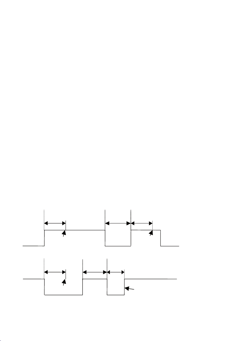
Digital Output
t
a
High level trigged input timing
≥
t
a
Trig
Trig
t
a
Low level trigged input timing
≥
t
a
Trig
No trig due to low
level shorter than t
a
t
a
<t
a
The digital output gives the following functionality:
1. Output Contact
The modem has a change over relay output (SPDT-contact). This output can be
controlled by a remote modem through Transparent I/O and Output service in the
Generic I/O function. The output can also be programmed to follow the local DCD
or DTR signals.
2. Remotely controlled
The output can be programmed to follow a remote modem data input. A remote unit
can also set/reset the output as well as transferring a sequence of “set- and resets” of
the output.
3. Follow DCD/Network
The output can be programmable to follow the local DCD or DTR signal.
Digital Input
The digital input gives the following functionality:
1. Static input
A static digital level trigged input high or low triggers the Generic I/O. With a level
trigged input only the first entry in the Generic I/O list can be trigged by the I/O input.
The input is trigged when the selected level has been stable for ta ms. A new trig will not
occur until the input has return to the opposite state an back again.
Page 11
11
6618-2202
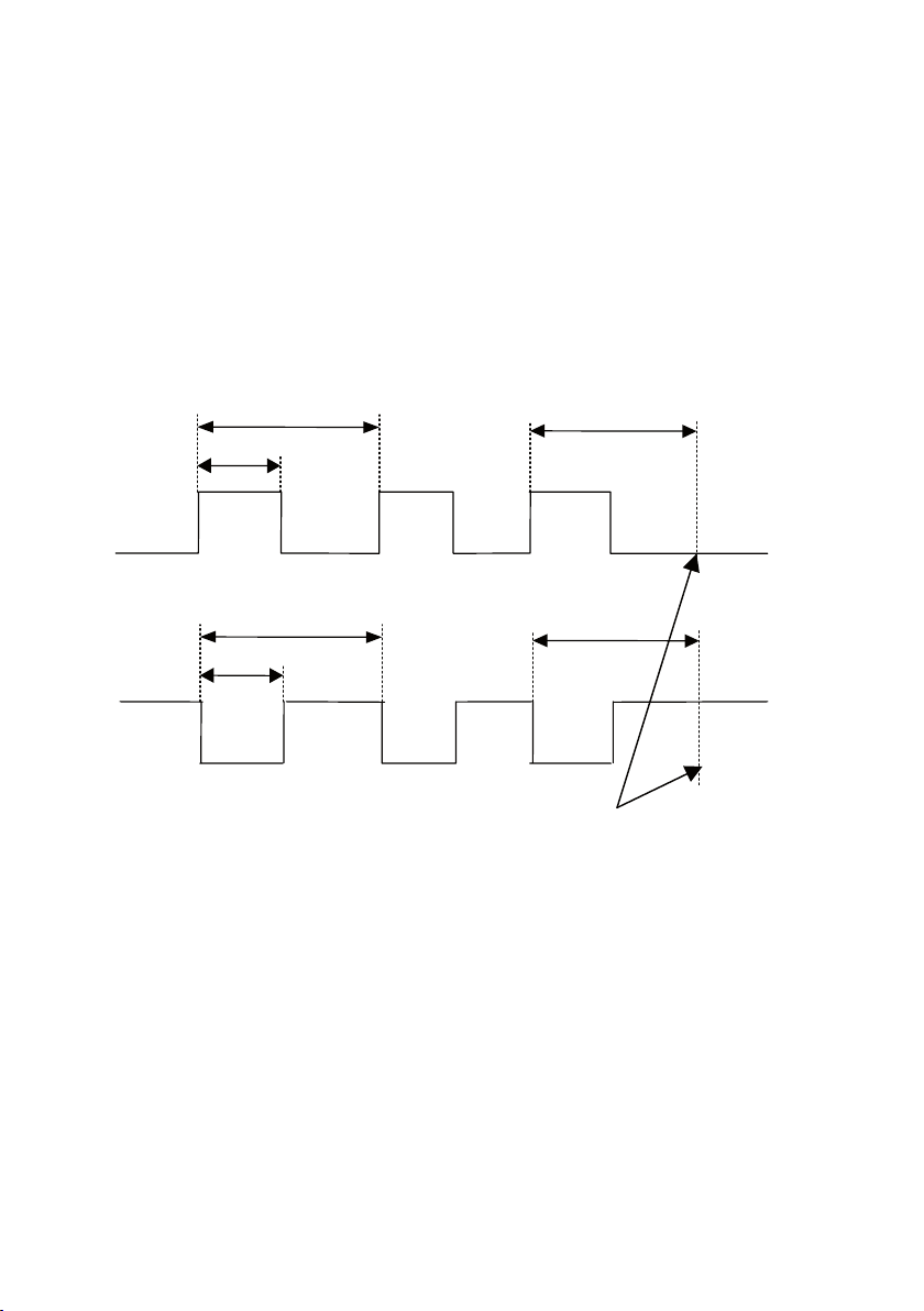
2. Pulsed Input
≥
t
a
≤
T
p
>Tp
≥
t
a
≤
T
p
>Tp
Positive edge trigged input timing
Negativ edge trigged input timing
Number of pulses counted
accumulated here
When input is set to edge trigged pulsed the number of pulses counted selects the entry
to be trigged.
For the pulsing of an input, some timings must be kept.
The input is filtered and pulses shorter than ta is discriminated. The time between pulses
must also be kept shorter than Tp. One other restriction on Tp is that Tp ≥ 2ta.
When time between pulses exceeds Tp the number of pulses are accumulated and an
entry selected by number of pulses counted.
The parameter ta is also used when output pulsing is selected.
The parameters ta and Tp are programmable from 10 ms to 2550 ms.
Page 12

12
6618-2202
Interface specifications
Power AV
Rated voltage 20 to 250 VDC
Operating voltage 18 to 300 VDC
Rated current
Rated frequency DC: –
Inrush current I2t 0.45 A2s
Startup current* 0.25 Apeak
Polarity Polarity independent
Isolation to All other ports 3 kVrms 50 Hz 1 min
Connection Detachable screw terminal
Connector size 0.2 – 2.5 mm2 (AWG 24-12)
Shielded cable Not required
Power LV
Rated voltage 12 to 48 VDC
Operating voltage 10 to 60 VDC
Rated current 150 mA @ 12 VDC
Rated frequency DC: –
Inrush current I2t 0.25 A2s
Startup current* 0.30 Apeak
Polarity Polarity independent
Isolation to All other ports 3 kVrms 50 Hz 1 min
Connection Detachable screw terminal
Connector size 0.2 – 2.5 mm2 (AWG 24-12)
Shielded cable Not required
* External supply current capability for proper startup
24 to 240 VAC
22 to 264 VAC
125 mA @ 18 VDC
15 mA @ 110 VDC
8 mA @ 250 VDC
120 mA @ 22 VAC
35 mA @ 95 VAC
28 mA @ 240 VAC
AC: 48 – 62 Hz
12 to 27 VAC
10 to 30 VAC 48 – 62 Hz
70 mA @ 24 VDC
40 mA @ 48 VDC
150 mA @ 12 VAC
70 mA @ 24 VAC
AC: 48 – 62 Hz
Page 13

13
6618-2202
Public Switched Telephone Network (PSTN)
Electrical specification Public Switched Telephone Network
Data rate 300 bit/s – 33.6 kbit/s
Protocol B103, B212, V21, V22, V22B, V23C, V23 HDX, V32, V32B, V34
Protection Installation Fault Tolerant (up to ±60 V)
Isolation to Power port 3 kVrms 50 Hz 1 min
Leased Line 2 kVrms 50 Hz 1 min
RS-232 2 kVrms 50 Hz 1 min
RS-485 2 kVrms 50 Hz 1 min
I/O 2 kVrms 50 Hz 1 min
Connection RJ-11C and Detachable screw terminal
Connector size Detachable screw terminal 0.2 – 2.5 mm2 (AWG 24 – 12)
Shielded cable Not required
Leased Line (LL)
Electrical specification 2- or 4-wire Leased Line
Data rate 300 bit/s – 33.6 kbit/s
Protocol B103, B212, V21, V22, V22B, V23C, V23 HDX, V32, V32B, V34
Transmission range PSTN 30 dB
Budget Leased Line max 40 dB
Protection Installation Fault Tolerant (up to ± 60 V)
Isolation to Power port 3 kVrms 50 Hz 1 min
Leased Line 2 kVrms 50 Hz 1 min
RS-232 2 kVrms 50 Hz 1 min
RS-485 2 kVrms 50 Hz 1 min
I/O 2 kVrms 50 Hz 1 min
Connection Detachable screw terminal
Connector size 0.2 – 2.5 mm2 (AWG 24 – 12)
Shielded cable Not required
Page 14

14
6618-2202
RS-422/485
Electrical specification EIA/TIA-485 ITU V.11
2-wire or 4-wire twisted pair
Data rate 300 bit/s – 115.2 kbit/s
Data format 7 or 8 data bits, Odd, even or none parity, 1 or 2 stop bits.
9-12 bit words
Protocol Transparent
Retiming Yes
Turn around time <10 µs (half duplex)
Transmission range ≤ 1200 m, depending on data rate and cable type (EIA RS-485)
Settings 120 W termination and failsafe biasing 680 W
Protection Installation Fault Tolerant (up to ±60 V)
Isolation to Power port 3 kVrms 50 Hz 1 min
PSTN Line 2 kVrms 50 Hz 1 min
Leased Line 2 kVrms 50 Hz 1 min
I/O 1.5 kVrms 50 Hz 1 min
Galvanic connection to RS-232
Connection Detachable screw terminal
Connector size 0.2 – 2.5 mm2 (AWG 24 – 12)
Shielded cable Not required*
Miscellaneous Do not connect RS-232 and RS-422/485 simultaneously
RS-232
Electrical specification EIA/TIA-232
Data rate 300 bit/s – 115.2 kbit/s
Data format 7 or 8 data bits, Odd, even or none parity, 1 or 2 stop bits.
9-12 bit words
Protocol Transparent
Retiming Yes
Transmission range Cable length ≤ 15 m
Isolation to Power port 3 kVrms 50 Hz 1 min
PSTN Line 2 kVrms 50 Hz 1 min
Leased Line 2 kVrms 50 Hz 1 min
I/O 1.5 kVrms 50 Hz 1 min
Galvanic connection to RS-485
Connection 9-pin D-sub female (DCE)
and Detachable screw terminal (DCE )
Connector size Detachable screw terminal 0.2 – 2.5 mm2 (AWG 24 – 12)
Shielded cable Not required*
Miscellaneous Do not connect RS-232 and RS-422/485 simultaneously
* Railway installation close to the rails.
For a cable located within 3 m and connected to this port, the use of shielded cable is recommended, this is
to minimise the risk of interference. The cable shield should be properly connected (360°) to an earthing point
within 1 m of this port. This earthing point should have a low impedance connection to the conductive enclosure of the apparatus cabinet, or similar, where the unit is built-in. This conductive enclosure should be connected to the earthing system of an installation and may be directly connected to the protective earth.
Page 15

15
6618-2202
Generic I/O interface Input
Electrical specification Opto isolated input
Input voltage range 0 – 60 VDC
Input current 5 mA @ 60 VDC
Input inactive Uin < 2.5 V
Input active Uin >5.0 V
Transmission range Cable length ≤ 15 m
Connection Detachable screw terminal (DCE )
Connector size 0.2 – 2.5 mm2 (AWG 24 – 12)
Isolation to Power port 3 kVrms 50 Hz 1 min
PSTN line 2 kVrms 50 Hz 1 min
Leased Line 2 kVrms 50 Hz 1 min
RS-232 2 kVrms 50 Hz 1 min
RS-485 2 kVrms 50 Hz 1 min
I/O output 2 kVrms 50 Hz 1 min
Shielded cable Not required*
Generic I/O interface Relay Output
Electrical specification One change over contact
Switching voltage Max 40 V AC/DC
Switching current Max 500 mA AC/DC
Electrical endurancee 5 x 10⁵ operations at 20 W / 20 VA Resistive load
Transmission range Cable length ≤ 15 m
Connection Detachable screw terminal (DCE )
Connector size 0.2 – 2.5 mm2 (AWG 24 – 12)
Isolation to Power port 3 kVrms 50 Hz 1 min
PSTN line 2 kVrms 50 Hz 1 min
Leased Line 2 kVrms 50 Hz 1 min
RS-232 1.5 kVrms 50 Hz 1 min
RS-485 1.5 kVrms 50 Hz 1 min
I/O input 2 kVrms 50 Hz 1 min
Shielded cable Not required*
* Railway installation close to the rails.
For a cable located within 3 m and connected to this port, the use of shielded cable is recommended, this is
to minimise the risk of interference. The cable shield should be properly connected (360°) to an earthing point
within 1 m of this port. This earthing point should have a low impedance connection to the conductive enclosure of the apparatus cabinet, or similar, where the unit is built-in. This conductive enclosure should be connected to the earthing system of an installation and may be directly connected to the protective earth.
Page 16

16
6618-2202
RS-232 (DCE)
Position
D-sub
Screw
terminal
Direction* Description
D-sub
description
No. 1 No. 4 Out Data Carrier Direct (DCD)
No. 2 No. 7 Out Received Data (RD)
No. 3 No. 8 In Transmitted Data (TD)
No. 4 No. 3 In Data Terminal Ready (DTR)
No. 5 No. 1 Not Connected Signal Ground (SG)
No. 6 No. 2 Out Data Set Ready (DSR)
1
6
2
7
3
8
4
9
5
No. 7 No. 6 In Request To Send (RTS)
No. 8 No. 5 Out Clear To Send (CTS)
No. 9 No. 9 Out Ring Indicator (RI)
* Direction relative to this unit.
Leased Line
Position Direction Description Product marking
No. 1 In/Out 2-wire Receive/ Transmit LL1
No. 2 In/Out 2-wire Receive/ Transmit LL2
PSTN
Position Product marking
RJ-11C
a – Not Connected
b In/Out PSTN Transmit/ Receive
c No. 2 In/Out PSTN Transmit/ Receive
d No. 1 In/Out PSTN Transmit/ Receive
e In/Out PSTN Transmit/ Receive
f – Not Connected
* Direction relative to this unit. ** The PSTN screw terminals are shared with 2-wire Leased Line.
Screw
terminal**
Direction* Description RJ-11C Screw terminal
Disconnects from “pin c”
when the modem goes
Off-Hook
LL2
LL1
Disconnects from “pin c”
when the modem goes
Off-Hook
Page 17

17
6618-2202
LED Indicators
(for details see page 22)
Power
Position Direction* Description Product marking
No. 1 In AC: Neutral
DC: –Voltage
No. 2 In AC: Line
DC: +Voltage
* Direction relative to this unit.
Page 18

18
6618-2202
RS-232 (DCE)
Position
D-sub
Screw
terminal
Direction* Description
No. 1 No. 4 Outd Data Carrier Direct (DCD)
No. 2 No. 7 Out Received Data (RD)
No. 3 No. 8 In Transmitted Data (TD)
No. 4 No. 3 In Data Terminal Ready (DTR)
No. 5 No. 1 Not Connected Signal Ground (SG)
No. 6 No. 2 Out Data Set Ready (DSR)
No. 7 No. 6 In Request To Send (RTS)
No. 8 No. 5 Out Clear To Send (CTS)
No. 9 No. 9 Out Ring Indicator (RI)
* Direction relative to this unit.
Leased Line
Position Direction* Description Product marking
No. 1 Out 4-wire Transmit LL1
In/Out 2-wire Receive/ Transmit
No. 2 Out 4-wireTransmit LL2
In/Out 2-wire Receive/ Transmit
No. 3 In 4-wire Receive LL3
In/Out 2-wire Receive/ Transmit at
No. 4 In 4-wire Receive LL4
In/Out 2-wire Receive/ Transmit at
Leased Line PSTN backup
Leased Line PSTN backup
D-sub
description
1
6
2
7
3
8
4
9
5
PSTN
Position Product marking
RJ-11C
a – Not Connected
b In/Out PSTN Transmit/ Receive
c No. 2 In/Out PSTN Transmit/ Receive
d No. 1 In/Out PSTN Transmit/ Receive
e In/Out PSTN Transmit/ Receive
f – Not Connected
* Direction relative to this unit. ** The PSTN screw terminals are shared with 2-wire Leased Line.
Screw
terminal**
Direction* Description RJ-11C Screw terminal
Disconnects from “pin c”
when the modem goes
Off-Hook
LL2
LL1
Disconnects from “pin c”
when the modem goes
Off-Hook
Page 19

19
6618-2202
LED Indicators
(for details see page 22)
Power
Position Direction* Description Product marking
No. 1 In AC: Neutral
DC: –Voltage
No. 2 In AC: Line
DC: +Voltage
* Direction relative to this unit.
RS-422/485
Position Direction* Description Product marking
No. 1 In R+ ( A’) Receive RS-422/485 4-wire R+
No. 2 In R– (B’) Receive RS-422/485 4-wire R–
No. 3 Out T+ (A) Transmit RS-422/485 4-wire T/R+
In/Out T+ (A/A’) Transmit/Receive RS-485 2-wire
No. 4 Out T– (B) Transmit RS-422/485 4-wire T/R–
In/Out T+ (A/A’) Transmit/Receive RS-485 2-wire
* Direction relative to this unit
I/O Input/Relay Output
Position Direction* Description Product marking
No. 1 In Input + +
No. 2 In Input – –
No. 1 In/Out Normal
closed contact
No. 2 In/Out Common
contact
No. 3 In/Out Normal
open contact
NC
C
NO
Page 20

20
6618-2202
LED Indicators
LED Status Description
TD
Transmit data
RD
Receive data
RTS
Request
to send
DCD
Data carrier
detect
DTR
Data terminal
ready
REL
Reliable mode
LINE OFF The modem is on-hook
PWR
Power
Only for TD-36 485
I/O IN OFF The I/O input is inactive
I/O OUT OFF The I/O output is inactive, C and NC connected
OFF No data
ON / FLASH The modem receiving data on the DTE interface
OFF No data
ON / FLASH The modem transmitting data on the DTE interface
OFF RTS signal is inactive
ON RTS signal is active
OFF DCD signal is inactive
ON DCD signal is active, modem has detected a carrier or the signal is
set to always ON
OFF DTR signal is inactive
ON DTR signal is active
OFF Reliable mode is OFF, direct or normal mode
ON Reliable mode is ON
FLASH Reliable mode with error correction and compression
ON The modem is off-hook with an established connection
FLASH Line backup interface in use
OFF The modem has no power
ON The modem is up and running
ON The I/O input is active
ON The I/O output is active, C and NO connected
Page 21

21
6618-2202
DIP-switch settings
S4 S3
S5S2S1
Before DIP-switch settings:
Prevent damage to internal electronics from electrostatic discharges (ESD)
by discharging your body to a grounding point (e.g. use of wrist strap).
NOTE DIP-switch alterations are only effective after a power on.
S1 DIP-switch
Stored values / Auto detect
ON
1 2 3 4 5 6 7 8
Use stored values
* 300 and 600 baud not supported
ON
1 2 3 4 5 6 7 8
Auto detect*
S1 DIP-switch
Selection of DTE speed
ON
1 2 3 4 5 6 7 8
ON
1 2 3 4 5 6 7 8
ON
1 2 3 4 5 6 7 8
ON
1 2 3 4 5 6 7 8
ON
1 2 3 4 5 6 7 8
300 bit/s
600 bit/s
1200 bit/s
2400 bit/s
4800 bit/s
ON
1 2 3 4 5 6 7 8
ON
1 2 3 4 5 6 7 8
ON
1 2 3 4 5 6 7 8
ON
1 2 3 4 5 6 7 8
ON
1 2 3 4 5 6 7 8
9600 bit/s
19.2 kbit/s
38.4 kbit/s
57.6 kbit/s
115.2 kbit/s
Page 22

22
6618-2202
S1 DIP-switch
Selection of DTE format
ON
1 2 3 4 5 6 7 8
ON
1 2 3 4 5 6 7 8
ON
1 2 3 4 5 6 7 8
ON
1 2 3 4 5 6 7 8
ON
1 2 3 4 5 6 7 8
ON
1 2 3 4 5 6 7 8
ON
1 2 3 4 5 6 7 8
ON
1 2 3 4 5 6 7 8
7E 1S
7O 1S
8N 1S
8E 1S
8O 1S
Direct mode 8E1 or 8O1. 8O1
in command mode
Direct mode 7E1 or 7O1. 8N1
in command mode
7N 2S
S2 DIP-switch
Leased Line Mode selection
ON
1 2 3 4 5 6 7 8
ON
1 2 3 4 5 6 7 8
Leased Line disable, PSTN enable
Leased Line answering
ON
1 2 3 4 5 6 7 8
ON
1 2 3 4 5 6 7 8
ON
1 2 3 4 5 6 7 8
ON
1 2 3 4 5 6 7 8
ON
1 2 3 4 5 6 7 8
ON
1 2 3 4 5 6 7 8
ON
1 2 3 4 5 6 7 8
ON
1 2 3 4 5 6 7 8
7E 2S
7O 2S
8N 2S
8E 2S
8O 2S
Direct mode 8E2 or 8O2. 8N2
in command mode
Direct mode 7E2 or 7O2.8N2
in command mode
Leased Line calling
S2 DIP-switch
DTE interface selection
ON
1 2 3 4 5 6 7 8
RS-422/485 disabled,
RS-232 enabled
S2 DIP-switch
RS-422/485
ON
1 2 3 4 5 6 7 8
RS-422/485, 2-wire
ON
1 2 3 4 5 6 7 8
ON
1 2 3 4 5 6 7 8
RS-422/485 enabled,
RS-232 disabled
RS-422/485, 4-wire
Page 23

23
6618-2202
S2 DIP-switch
Leased Line 2/4 wire selection
ON
1 2 3 4 5 6 7 8
Leased Line 2-wire
ON
1 2 3 4 5 6 7 8
Leased Line 4-wire
S2 DIP-switch
Selection PSTN backup of Leased Line
ON
1 2 3 4 5 6 7 8
Backup of Leased Line disabled
ON
1 2 3 4 5 6 7 8
Backup of Leased Line enabled
S2 DIP-switch
Selection of answering/calling mode for PSTN backed up Leased Line
ON
1 2 3 4 5 6 7 8
Answering
ON
1 2 3 4 5 6 7 8
Calling
S2 DIP-switch
Remote configuration control
ON
1 2 3 4 5 6 7 8
Use stored values
ON
1 2 3 4 5 6 7 8
Remote configuration disabled
S3 DIP-switch
Dial abort
ON
1 2 3 4 5 6 7 8
Use stored values
ON
1 2 3 4 5 6 7 8
Dial abort disabled (AT&A1)
S3 DIP-switch
Blind dialing
ON
1 2 3 4 5 6 7 8
Use stored values
S3 DIP-switch
Line mode setting
ON
1 2 3 4 5 6 7 8
ON
1 2 3 4 5 6 7 8
Use stored values
Buffer mode enabled (AT\N0)
ON
1 2 3 4 5 6 7 8
ON
1 2 3 4 5 6 7 8
ON
1 2 3 4 5 6 7 8
Enable blind dialing (ATX3)
Reliable mode enabled (AT\N2)
Direct Mode enabled (AT\N1)
Page 24

24
6618-2202
S3 DIP-switch
PLC parameter setting
ON
1 2 3 4 5 6 7 8
Use stored values
ON
1 2 3 4 5 6 7 8
PLC settings
(ATQ1E0&C1&K0&A1)
S3 DIP-switch
Flow control DTE interface
ON
1 2 3 4 5 6 7 8
Use stored value for AT&Kn
ON
1 2 3 4 5 6 7 8
RTS/CTS flow control enable
(AT&K3)
S3 DIP-switch
Leased Line termination
ON
1 2 3 4 5 6 7 8
ON
1 2 3 4 5 6 7 8
Termination disabled
Termination of Transmitter / Receiver
in 2-wire mode and Transmitter in
4-wire mode
ON
1 2 3 4 5 6 7 8
ON
1 2 3 4 5 6 7 8
Termination of Receiver
in 4-wire mode
Termination of both Transmitter
and Receiver in 4-wire mode
S4 DIP-switch
Set modem to factory default
ON
1 2 3 4 5 6 7 8
Use stored values
* Don’t leave S4:1 in ON position if not intending to restore factory setting at every power on.
ON
1 2 3 4 5 6 7 8
Restore factory default setting*
S4 DIP-switch
DCD, DTR and DSR control
ON
1 2 3 4 5 6 7 8
Use stored values
S4 DIP-switch
Data compression control
ON
1 2 3 4 5 6 7 8
Use stored values
S4 DIP-switch
Auto retrain control
ON
1 2 3 4 5 6 7 8
Use stored values
ON
1 2 3 4 5 6 7 8
ON
1 2 3 4 5 6 7 8
ON
1 2 3 4 5 6 7 8
DCD and DSR always on, DTR
ignored (AT&C0&D0&S0)
Data compression disabled
(AT%C0)
Auto retrain disabled (AT%E0)
Page 25

25
6618-2202
S4 DIP-switch
Selection of line speed and modulation
ON
1 2 3 4 5 6 7 8
ON
1 2 3 4 5 6 7 8
ON
1 2 3 4 5 6 7 8
ON
1 2 3 4 5 6 7 8
ON
1 2 3 4 5 6 7 8
ON
1 2 3 4 5 6 7 8
ON
1 2 3 4 5 6 7 8
ON
1 2 3 4 5 6 7 8
Use saved parameters defined by
AT+MS
V.21 300
V.23 1200 hdx
V.22 1200
V.22bis 2400
V.32bis 4800
V.32bis auto
V.32bis 9600
S5 DIP-switch
RS-422/485 termination
ON
No termination
1 2 3 4
ON
Termination of both T and R in 2-wire
connection
1 2 3 4
ON
1 2 3 4 5 6 7 8
ON
1 2 3 4 5 6 7 8
ON
1 2 3 4 5 6 7 8
ON
1 2 3 4 5 6 7 8
ON
1 2 3 4 5 6 7 8
ON
1 2 3 4 5 6 7 8
ON
1 2 3 4 5 6 7 8
ON
1 2 3 4
ON
1 2 3 4
V.34, 9600
V.32bis 14400
V.34 19200
V.34 24000
V.34 28 800
V.34 33600
Automatic line speed
Termination of R in 4-wire connection
Termination of both T and R in 4-wire
connection
Factory default
ON
1 2 3 4 5 6 7 8
ON
S1
1 2 3 4 5 6 7 8
S2
ON
1 2 3 4 5 6 7 8
S3
ON
1 2 3 4 5 6 7 8
ON
S4
1 2 3 4
S5
Page 26

26
6618-2202
V.23 2- / 4-wire HDX- / FDX-leased line settings for TD-36 485
S1 DIP-switch
Selection of DTE speed
ON
1 2 3 4 5 6 7 8
S1 DIP-switch
Selection of DTE-format
ON
1 2 3 4 5 6 7 8
ON
1 2 3 4 5 6 7 8
S2 DIP-switch
Leased line mode selection
ON
1 2 3 4 5 6 7 8
S2 DIP-switch
Leased line 2/4-wire selection
ON
1 2 3 4 5 6 7 8
1200 bit/s
8E1, 8O1, 8O1
in command mode
7E1, 7O1, 8N1, 8N1
in command mode
1200 bit/s leased line /mulidrop
2-wire leased line
ON
1 2 3 4 5 6 7 8
ON
1 2 3 4 5 6 7 8
ON
1 2 3 4 5 6 7 8
8E2, 8O2, 8N2
in command mode
7E2, 7O2, 8N2, 8N2
in command mode
4-wire leased line
S3 DIP-switch
Carrier active using RTS or incoming data
ON
1 2 3 4 5 6 7 8
Incoming data
S4 DIP-switch
V.23 line modulation
ON
1 2 3 4 5 6 7 8
V.23 1200 HDX/FDX
S4 DIP-switch
Permanent carrier control
ON
1 2 3 4 5 6 7 8
Disabled
ON
1 2 3 4 5 6 7 8
ON
1 2 3 4 5 6 7 8
RTS controlled
Enabled
Page 27

27
6618-2202
S3 DIP-switch
V.23 leased line termination*
ON
1 2 3 4 5 6 7 8
ON
1 2 3 4 5 6 7 8
Termination disabled
Termination of receiver
in 4-wire mode
* The leased line should be terminated at the end points.
ON
1 2 3 4 5 6 7 8
ON
1 2 3 4 5 6 7 8
Termination of transmitter /
receiver in 2-wire mode and
Transmitter in 4-wire mode
Termination of both transmitter /
receiver in 4-wire mode
Termination recommandations of Leased lines
and Dial-up connections
In some connections the communication line (Leased Line or PSTN) must be
terminated. The table below shows the right way to activate the termination
for different usages. As a standard, the receiver in multidrop systems at the end
points shall be terminated.
S3 DIP-switch
Termination recomendations for TD-36 485
ON
1 2 3 4 5 6 7 8
ON
1 2 3 4 5 6 7 8
ON
1 2 3 4 5 6 7 8
ON
1 2 3 4 5 6 7 8
PSTN
PSTN
Backup
2-wire
Leased Line
4-wire
Leased Line
ON
1 2 3 4 5 6 7 8
ON
1 2 3 4 5 6 7 8
ON
1 2 3 4 5 6 7 8
ON
1 2 3 4 5 6 7 8
Multidrop
V23 2-wire – endunit
Multidrop
V23 2-wire – dropunit
Multidrop
V23 4-wire – endunit
Multidrop
V23 4-wire – dropunit
Page 28

28
6618-2202
=Termination
T
D-36 485
Slave unit Slave unit Slave unit
T
D-36 485
Slave unit Slave unit Slave unit
Max 0.3 metre
=Termination
T+
T–
T+T- T+T- AB
R+
R–
T+
T–
R– R+ R+T– T– B’ A’ BAT+T+ R–
RS-422/485 general advice
4-wire termination
2-wire termination
Termination recommendations
The RS-422/485 line must be terminated. In the TD-36 485, the termination is combined
with fail-safe functionality. The termination is used to prevent undefined states when the
bus is in tri-state condition.
… Using 2-wire RS-485 both ends should be terminated.
… Using 4-wire RS-485 both pairs shall be terminated at both ends.
… Using 4-wire RS-422 it’s only necessary to terminate the receivers.
RS-422/485 connection pins can be differently named. For some equipment brands
the T+ corresponds to A, but other brands might use some other naming convention.
If a unit does not work it can help to swap A and B.
Page 29

29
6618-2202
CLICK!
Mounting
This unit should be mounted on 35 mm DIN-rail, which is
horizontally mounted inside an apparatus cabinet, or similar.
Snap on mounting, see figure.
Cooling
This unit uses convection cooling. To avoid
obstructing the airflow around the unit, use the
following spacing rules. Minimum spacing 25 mm
(1.0 inch) above /below and 10 mm (0.4 inches)
left /right the unit. Spacing is recommended for
the use of unit in full operating temperature
range and service life.
* Spacing (left/right) recommended for
full operating temperature range
10 mm *
(0.4 inches)
25 mm
25 mm
Removal
Press down the black support at the back of the unit
using a screwdriver, see figure.
Page 30

30
6618-2202
Windows configuration tool TD-Tool
The TD-Tool is a PC – application program with a graphical interface for easy configuration of the complex functions found on the encolsed CD or at the Westermo website.
Please refer to TD-Tool for a complete description of the functionality of the Windows
program.
AT-Commands
Please refer to the AT Commands Interface Guide found on the enclosed CD or at
the Westermo website for a complete list of all available AT-commands and a detailed
description of the serial AT-command interface.
Configuration
The TD-36 (485) can be configured both from the local DTE interface and remotely over
the PSTN network. Whether the local or remote interface is used the configuration can
be made with AT-commands or with a PC-based application configuration tool. Basic
configurations can also be made with DIP switches locally.Remote configuration
The TD-36 (485) can be configured from a remote modem. To configure a TD-36 (485)
any GSM, ISDN or PSTN modem can be used.
The modem used to configure is referred as the “local modem”.
Please make sure that the remote TD-36 (485) is connected to the PSTN network and is
powered up.
… Connect the local modem to it's media (ISDN, PSTN or GSM)
… Connect the PC's com-port to the DTE interface of the local modem.
… Connect the power supply.
… Start a terminal emulation program (i.e. Windows Hyper-Terminal).
… Configure the local modem data rate and word format.
… Set up a connection to the remote TD-36 (485) to be configured by using the
normal dial command: ATD<No><CR>. When connected send the remote escape
sequence <++++>. The called remote TD-36 (485) will acknowledges by requesting the remote password. Enter the correct password (default: no password, just
return). Next; configure the remote TD-36 (485) using AT-commands. The password for remote configuration is defined with AT*WRCP – Remote configuration
password.
… Configure the parameter on the remote TD-36 (485) from your terminal program
and save the settings with AT&W.
… Hang up the connection using the ATH command.
Page 31

31
6618-2202
Application examples
DTR
DSR
DCD
… TD-36 connected to TD-36 with DTR signal call
PSTN
Network
Configure the units
AT&F Set the unit to factory default
AT&W Store default settings
Set up the connection – The dialling modem
AT&Z0=nnn Store the number of the remote modem in the dialling TD-36
AT&S0 Set DSR signal always high (if this signal is used to trig the DTR)
AT&B1 Activates automatic DTR dialling if DTR switches from low (OFF)
AT&W Save settings
Switch DTR from
OFF to ON
to high (ON)
The modem will now dial the phone number stored in the first location of
the telephone number table (AT&Z0=<nnn>)
Set up the connection – The answering modem
ATA Enter the answer command when RING comes from the network or set up
NOTE: If no valid DTR signal can be provided by external application, the modems DSR signal can
be used to trig the transmission. Connect the DSR signal via a relay, or other potential
free contact, to the DTR signal. A 10 kohm pull down resistor should also be connected
between the DTR and a signal that is always low e.g. the DCD.
ATS0=1 to auto answer on 1 RING signal (or more than 1)
Relay
External
application
10 kohm
May be required in harsh environments.
Page 32

32
6618-2202
… Frequently used settings for PLC-systems
PSTN
Network
Most PLC-systems and other industrial applications where modems are used require the
same changes to the standard settings.
The most commonly encountered problems concern speed, parity and control signals
from the connected equipment.
Speed and parity are changed with the switches under the cover in block S1. If this action
does not solve the problem the modem’s answering codes and possible echoing of commands might be the source of the difficulty.
Below follows a list of commands that might resolve the problems. The commands may
of course be placed on one single command line if desired.
Configure the TD-36 connected to the PLC
AT&F Set the unit to factory default.
ATV0 Gives the answering codes in short format. (digits)
ATQ1 No result codes are sent on the RS-232/V.24 connection.
ATE0 Commands that are sent from the terminal/computer etc.
AT&C1 DCD will follow the carrier on the line.
AT&K0 No handshaking.
AT&A1 Character abort option OFF.
AT&W Store default settings.
Note: S3:5 may be used for this purpose.
are not echoed back to the RS-232/V.24 connection.
Page 33

33
6618-2202
… Leased Line connection using 2- or 4-wire
Leased Line
Leased Line connections can be set up using 2-wire (or 4-wire in TD-36 485).
When renting a 4-wire line from a telephone company one pair of cables for
transmission and one pair for reception are usually provided.
The maximum transmission distance depends on the attenuation of the line.
The maximum value is theoretically 30 dBm. To have a good error rate it is
recommended to keep the attenuation under 25 dB. When renting lines from a telephone
company a longer transmission distance is normally possible as the signals are probably
transmitted over PCM-lines, i.e.
fibre optic or other media with low attenuation.
To set the modem for leased line applications use the dip switches.
Configure the units
S2:1, 2 ON
S2:2 ON
S2:5 OFF Leased line 2-wire
S1 Sets speed and parity for the RS-232 port.
S4 Decides line-speed. Must be set in direct mode applications.
To make switch setting active the power must be cycled OFF ≥ ON.
Leased line calling
Leased line answering
Resistance, attunation and distance for different wires
Tele Cable Area Resistance for
double cable
Ø 0,5 mm* ≈ 0,2 mm² 175 W/km 1,1 dB/km 23 km 27 km
Ø 0,6 mm* ≈ 0,3 mm² 123 W/km 0,9 dB/km 28 km 33 km
Ø 0,7 mm* ≈ 0,4 mm² 93 W/km 0,8 dB/km 31 km 38 km
Ø 0,8 mm ≈ 0,5 mm² 73 W/km 0,7 dB/km 36 km 43 km
Ø 0,9 mm ≈ 0,64 mm² 59 W/km 0,6 dB/km 42 km 50 km
* Frequently used in the local network
Attunation Recommended
Max distance
(25 dB)
Max Distance
(30 dB)
Page 34

34
6618-2202
… TD-36 – Secure Call-back
The TD-36 is connected to a PLC which one want to restrict access to. The TD-36 can
support access control through the Secure Callback function. In this example password
and callback to a predefined number is chosen. The modem in the calling end is here
chosen to be a PSTN modem, but can be any of the PSTN, ISDN or GSM modem from
the Westermo product range.
The DTE serial speed between the PLC – TD-36 and TDW-33 – PC is assumed to be
9600 8N1 but can be chosen to fit the actual system requirement.
PSTN
Network
Configure the TD-36
AT&F Set the unit to factory default
AT+IPR=9600 DTE baudrate 9600
AT+ICF=3,4 Character framing 8 data, 1 stop, parity none
ATS0=1 Auto answer after first ring
ATQ1E0&C1&K0&A1 Suitable for PLC communication
AT&W Store default settings
AT*WCB=4 Callback enabled, Password and callback number stored
AT*WCBTAB=1,”+4670428000”,
”n3Y9kA6otYZu8”
AT*WCBTIME=10 Define delay time between hangup an callback
in one or more positions of wcbtab
Define callback number 1
When password 1 is entered number +4670428000 will
be called
The TD-36 will wait 10s after hangup to callback
to allow the analogue modem to hangup
Page 35

35
6618-2202
Configure the TDW-33
AT&F Set the unit to factory default
AT+IPR=9600 DTE baudrate 9600
AT+ICF=3,4 Character framing 8 data, 1 stop, parity none
ATS0=1 Auto answer after first ring
AT&W Store default settings
Set up the connection
The dialling modem
TDW-33
ATD0705123456 TD-36 answers the call and requests
CONNECT 9600 TD-36 verifies the password to the
NO CARRIER Wait 10 s The connection is broken and
CONNECT 9600 CONNECT 9600 Connection is established
The answering modem TD-36 Comment
Dial the number to TD-36
to TDW-33
Operator/system at
passwords stored and if true compare dissconnects.
TDW-33 enters
Password: n3Y9kA6otYZu8
TD-36 waits the programmed 10s
for TDW-33 to disconnect
TD-36 dials +4670428000 The number programmed cor-
responding to the password is
dialled, preferable it’s the number
to the TDW-33
between the PC at TDW-33
and the PLC at TD-36
Page 36

36
6618-2202
… TD-36 – Silent answering on predefined number
The TD-36 is connected to a power meter which is remotely monitored. The TD-36
shares the PSTN line with normal telephones which is preferred not to give a ring signal
when the meter is read.
The TD-36 is configured to answer calls on the Caller ID received, the valid numbers to
answer is programmed into the TD-36. There exists a number of standards for sending
Caller ID check which standard is used by your operator. The TD-36 supports the major
implementations of Caller ID. In this example the DTMF Caller ID version is used.
Note that some implementations doesn’t give the possibility to make a silent answer
since the Caller ID is sent between first and second ring signal.
The modem in the calling end is here chosen to be a PSTN modem, but can be any of
the PSTN, ISDN or GSM modem from Westermo product range.
PSTN
Network
Configure the TD-36 connected to the power meter
AT&F Set the unit to factory default
AT+IPR=9600 DTE baudrate 9600
AT+ICF=3,4 Character framing 8 data, 1 stop, parity none
ATS0=0 No auto answer on Ring signals
ATQ1E0&C1&K0&A1 Suitable for PLC communication
AT&W Save settings
AT*WACCTAB=1,”016428000”
AT*WACCTAB=2,”016480250”
AT*WCID=3,3 Set Caller ID to A-number answer with DTMF coded numbers
Set the valid A-numbers for automatic answering
Page 37

37
6618-2202
… TD-36 485 2-wire half duplex
Te rmination
TD-36 485
1
2
T/R+
T/R-
3
4
In this application the TD-36 485 is set to communicate with a number of units with
RS-485 interface.
The communication is 2 wire half duplex at 38.4 kbit/s, 8 data, parity even and 1 stop bit.
PSTN
Network
Configure the TD-36 485
AT&F Set the unit to factory default
AT&W Store default settings
S2:3 ON RS-422/485 enable RS-232 disable
S2:4 OFF Select 2-wire RS-485
S1:4 ON 38.4 kbit/s
S1:7 ON 8 data bits even parity 1 stop bit
S3:8 ON Termination / Failsafe active
To make switch setting active the power must be cycled OFF -> ON.
Page 38

38
6618-2202
… Remote output and transparent mode
Alarm output
SMS Sending
Connection
Alarm Bell
Timeout
Timeout
retrigger
Timeout
retrigger
Timeout
Alarm
system
Alarm
output
I/O
Input
5 − 48 V
Acknowlidge
output
TD-36 485
5
6
7
8
9
IDW-90
Acknowlidge
Button
Alarm
Bell
5 − 48 V
I/O
Input
5
6
7
8
9
In this application the TD-36 485 I/O is used to send a SMS and then make an transparent I/O connection. The transparent I/O is in this example set up to an IDW-90 ISDN
modem, but can be any of the Westermo remote product supporting Generic I/O
(IDW-90, TD-36 485 and GDW-12).
The TD-36 485 has a alarm signal connected to it’s I/O input, when this input is activated
by the external alarm contact an SMS defined by Entry 1 in the entry list is sent. When
the SMS is transferred Entry 2 is programmed to be trigged. Entry 2 is programmed to
set up an Transparent I/O connection to an ISDN-modem IDW-90. The status of the
alarm signal will be transferred to the remote IDW-90 and activate an Alarm bell.
At this time the SMS should be available on the operators mobile showing the reason
for the alarm. The operator can acknowledge the alarm, the acknowledge signal will
now be transferred back to the originating TD-36 485 and alarm system. The alarm
system will deactivate the alarm output causing the remote alarm bell to stop sounding.
The Transparent I/O connection will be terminated by a programmed timeout.
GSM
Network
PSTN
Network
ISDN
Network
Page 39

39
6618-2202
Configure the TD-36 485
AT&F Set the unit to factory default
AT&W Store default settings
AT*WIOP=10,50,2,3,0 Set I/O params
AT*WIOL=1,2,5,0,0,070428000,
Temp. high server room,
+4670500899,1
AT*WIOL=2,7,2,60,0,+4616480250 Define Transparent I/O on entry 2
Min pulse time = 100 ms (10)
Pulse repetition = 500 ms (150)
Trig type = Pulsed trigged (2)
Pulse trig type = POS, pos edge (3)
Output type = No output (0)
Define SMS message on entry 1
Entry = 1 (1)
Service = SMS (2)
Retry = NEXT_ALLWAYS (5)
Timeout = 0
Priority = 0 Data 1 = SMS receiver number (070428000)
Data 2 = SMS text (Temp. high server room)
Data 3 = Service center Adress (+4670500899)
Data 4 = SMS protocol UDP (1)
Entry = 2 (2)
Service = TRANS (7)
Retry = RETRY_3 (2)
Timeout = 600s (60)
Priority = 0
Data 1 = Phone number of the remote IDW-90
(+4616480250)
Configure the IDW-90
S3:1,3,4 OFF S3:2 ON V.110 configured for GSM
To make switch setting active the power must be cycled OFF -> ON.
Activate events – The sending modem
I/O input pulsed with one puls SMS message transferred
and transparent I/O established
Testing by simulating the event
AT*WIOT=1 Force sending of SMS-message at entry 1
AT*WIOT=2 Force the transparent I/O connection to be established
Page 40

40
6618-2202
… TD-36 485 sending text message with SMS by usage of Generic I/O
5 – 48 V
Trigging SMS no 2
Trigging SMS no 3
Configure a TD-36 485 to send different SMS depending
on the I/O input pulse train.
PSTN
Network
GSM
Network
Configure the TD-36 485
AT&F Set the unit to factory default
AT&W Store default settings
AT*WIOP=5,10,2,3,0 Set I/O params
AT*WIOL=2,2,0,0,0,”num1”,”text1”,”
providernum1”,1,”password1”
AT*WIOL=3,2,0,0,0,”num2”,”text2”,”
providernum2”,1,”password2”
Min pulse time = 50 ms (5)
Max pulse time = 100 ms (10)
Trig type = Pulsed trigged (2)
Pulse trig type = POS, pos edge (3)
Output type = No output (0)
Entry = 2 (2)
Service = SMS (2)
Retry = NO (0)
Timeout = 0
Priority = 0
Data 1 = SMS receiver number (num1)
Data 2 = SMS text (text1)
Data 3 = SMS provider number (providernum1)
Data 4 = SMS protocol type UDP (1)
Data 5 = Password if required by provider (password1)
Entry = 3 (3)
Service = SMS (2)
Retry = NO (0)
Timeout = 0
Priority = 0
Data 1 = SMS receiver number (num2)
Data 2 = SMS text (text2)
Data 3 = SMS provider number (providernum2)
Data 4 = SMS protocol UDP (1)
Data 5 = Password if required by provider (password2)
Page 41

41
6618-2202
Send message
I/O input pulsed with two pulses
I/O input pulsed with three
pulses
SMS message text1 transferred to receiver num1
SMS message text2 transferred to receiver num2
Testing by simulating the event
AT*WIOT=2 Force sending of SMS-message at entry 2
AT*WIOT=3 Force sending of SMS-message at entry 3
Page 42

42
6618-2202
Alarm
system
Alarm
output
I/O
Input
5 − 48 V
Acknowlidge
output
TD-36 485
5
6
7
8
9
IDW-90
Acknowledge
Button
Alarm
Bell
5 − 48 V
I/O
Input
5
6
7
8
9
… Remote output and transparent mode
Alarm output
SMS Sending
Connection
Alarm Bell
Timeout
Timeout
retrigger
Timeout
retrigger
Timeout
In this application the TD-36 485 I/O is used to send a SMS and then make a transparent I/O connection. The transparent I/O is in this example set up to an IDW-90 ISDN
modem, but can be any of the Westermo remote products supporting Generic I/O (IDW90 or TD-36 485).
The TD-36 485 has a alarm signal connected to it’s I/O-input, when this input is activated
by the external alarm contact an SMS defined by Entry 1 in the entry list is sent. When
the SMS is transferred Entry 2 is programmed to be trigged. Entry 2 is programmed to
set up a Transparent I/O connection to an ISDN-modem IDW-90. The status of the alarm
signal will be transferred to the remote IDW-90 and activate an Alarm bell. At this time
the SMS should be available on the operators mobile showing the reason for the alarm.
The operator can acknowledge the alarm, the acknowledge signal will now be transferred
back to the originating TD-36 485 and alarm system. The alarm system will deactivate the
alarm output causing the remote alarm bell to stop sounding. The Transparent I/O connection will be terminated by a programmed timeout.
GSM
Network
PSTN
Network
ISDN
Network
Page 43

43
6618-2202
Configure the TD-36 485
AT&F Set the unit to factory default
AT&W Store default settings
AT*WIOP=10,50,2,3,1 Set I/O params
AT*WIOL=1,2,5,0,0,”070428000”,
“Temp. high server
room”,”+4670500899”,1, “password”
AT*WIOL=2,7,2,60,0,+4616480250 Define Transparent I/O on entry 2
Configure the IDW-90
S3:1,3,4 OFF S3:2 ON V.110 configured for GSM
To make switch setting active the power must be cycled OFF -> ON.
Min pulse time = 100 ms (10)
Pulse repetition = 500 ms (150)
Trig type = Pulsed trigged (2)
Pulse trig type = POS, pos edge (3)
Output type = output enabled (1)
Define SMS message on entry 1
Entry = 1 (1)
Service = SMS (2)Retry = NEXT_ALLWAYS(5)
Timeout = 0
Priority = 0
Data 1 = SMS receiver number (070428000)
Data 2 = SMS text (Temp. high server room)
Data 3 = Service center Adress (+4670500899)
Data 4 = SMS protocol UDP (1)
Entry = 2 (2)
Service = TRANS (7)
Retry =RETRY_3 (2) ;Do 3 connection attempts
Timeout = 600s (60)
Priority = 0
Data 1 = Phone number of the remote IDW-90
(+4616480250)
Activate events – The sending modem
IO input pulsed with one puls SMS message transferred and transparent IO established
Testing by simulating the event
AT*WIOT=1 Force sending of SMS-message at entry 1
AT*WIOT=2 Force the transparent I/O connection to be established.
Page 44

Westermo • SE-640 40 Stora Sundby, Sweden
Tel +46 16 42 80 00 Fax +46 16 42 80 01
Sales Units
Westermo Data Communications
E-mail: info@westermo.com
www.westermo.com
China
sales.cn@westermo.com
www.cn.westermo.com
France
infos@westermo.fr
www.westermo.fr
Germany
info@westermo.de
www.westermo.de
For complete contact information, please visit our website at www.westermo.com/contact
REV.G 6618-2202 2013-11 Westermo Teleindustri AB, Sweden – A Beijer Electronics Group Company
North America
info@westermo.com
www.westermo.com
Singapore
sales@westermo.com.sg
www.westermo.com
Sweden
info.sverige@westermo.se
www.westermo.se
or scan the QR code with your mobile phone.
United Kingdom
sales@westermo.co.uk
www.westermo.co.uk
Other Offices
 Loading...