

Page 1
Advanced Industrial
Telemodem
V.34
INSTALLATION MANUAL
6610-2203
www.westermo.com
TD-34
LV/HV
©
Westermo Teleindustri AB • 2005
Galvanic
Isolation
Transient
Protection
Balanced
Transmission
CE
Approved
Page 2

2 6610-2203
Table of Contents
1. Introduction
................................................................................................................................................. 3
1.1 Functional description
............................................................................................................... 4
2. Safety ........................................................................................................................................................................ 5
2.1 Approvals
.................................................................................................................................................. 6
2.2 Declaration of conformity
................................................................................................. 7
3. Specifications TD-34 LV and TD-34 HV ........................................... 8–9
4. Maintenance ............................................................................................................................................. 10
5. Installation ................................................................................................................................................... 10
5.1 Mounting /Removal
................................................................................................................ 10
5.2 Connections
........................................................................................................................... 11–17
5.2.1 Interface RS-232 9-pos D-sub
.................................................................... 12
5.2.2 Interface RS-232, 9-pos screw terminal
....................................... 12
5.2.3 Interface RS-485/422, 4-pos screw terminal
.......................... 13
5.2.4 Interface Leased Line
........................................................................................... 13
5.2.5 Interface Alarms
.......................................................................................................... 13
5.2.6 Interface RJ-11, PSTN
.......................................................................................... 13
5.3 Configuration
....................................................................................................................... 14–16
5.3.1 DIP switch settings TD-34
.................................................................... 14–16
5.4 LED Status Indicators
........................................................................................................ 17
6. AT Commands .......................................................................................................................... 18–42
7. Result Codes .................................................................................................................................. 43–44
8. S-registers ........................................................................................................................................... 45–52
9. Glossary .................................................................................................................................................. 53–55
10. Dialback application 1 ........................................................................................................... 56
11. Dialback application 2 ........................................................................................................... 57
12. Remote Access application ......................................................................................... 58
13. Schneider PLC application .......................................................................................... 59
Page 3
36610-2203
1. Introduction
The TD-34 is Westermo’s current top of the range analogue Telephone Modem intended for
use under the most extreme conditions.The TD-34 is the result of Westermo’s experience
and knowledge in the area of Industrial Telecommunication over more that 25 years. High
noise environments, difficult configurations and customer-specific applications can easily be
solved using TD-34 product.The philosophy for the TD-34 is based on quality and function
rather than optimizing for price. Nothing has been left to chance when designing this modem.
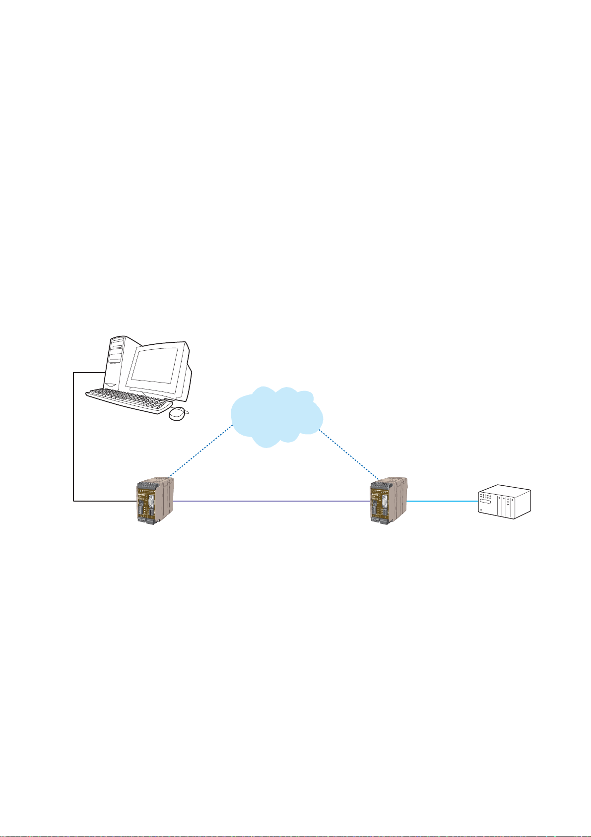
The TD-34 is an asynchronous modem with RS-232 and RS-485/422 interfaces built-in
as standard.The TD-34 can be used on standard PSTN “ Public Switched Telephone Network”
or Leased Lines consisting of either 2 or 4-wires for line connection.
The RS-485/422 interface can be configured as either end of line or intermediate using
2 or 4-wires.
The Opto-isolated Alarm interface on TD-34 may be used either for dial up based on a certain
event or as indication from the remote end. Indication of the state of the alarms is provided
on the front panel of the TD-34.
RS-232 2- or 4-wire leased line RS-232/422/485
TD-34TD-34
PSTN
Page 4

4 6610-2203
1.1 Functional description
The TD-34 has various interfaces that will cover most industrial applications.TD-34 is functionally complete industrial modem including alarm handling, leased line to PSTN redundancy,
Industrial Temperature Range, RS-232/422/485 interfaces and a power
supply interface with a wide input voltage range.All functional blocks are illustrated
in the figure below. A more detailed description can be found under chapter 3. Specifications
(page 8–9).
DP
CPU
Memory
ROM & RAM
MCU
Config.
DIP-switch
RS-232
RS-422/485
Leased
Line
Leased
Line
LED’s
+5V
0
IN
Isolated
power supply
Telephone
Line
Telephone
Line
Alarm in
Alarm out
Common
RS-232/V.24 RS-422/485
DAA
TTL
TTL
TTL
DAA
Page 5

56610-2203
2. Safety
General:
Before using this unit, read this manual completely and gather all information on the
unit. Make sure that you understand it fully. Check that your application does not
exceed the safe operating specifications for this unit.
Before installation, maintenance or modification work:
Prevent damage to internal electronics from electrostatic discharges (ESD)
by discharging your body to a grounding point (e.g. use of wrist strap).
Prevent access to hazardous voltages by disconnecting the unit from AC/DC
mains supply and all other electrical connections.
Installation:
This unit should only be installed by qualified personnel.
This unit should only be installed in a “restricted access area”, for example
a lockable cabinet where access is restricted to service personnel only.
This unit is intended for permanent connection to the AC/DC mains supply.
The power supply wiring must be sufficiently fused, and if necessary it must be possible to disconnect manually from the AC/DC mains supply. Ensure compliance to
national installation regulations.
Units with the rated voltage exceeding 42.4 V peak or 60 VDC, are defined as class I
equipment with a protective earthing conductor terminal.
Units with the rated voltage up to 42.4 V peak or 60 VDC, are defined as class III
equipment and shall be separated from hazardous voltage by double or reinforced
insulation.
This unit uses convection cooling.To avoid obstructing the air flow around the unit,
follow the spacing recommendations (see Installation section).
!
!
!
Page 6

6 6610-2203
For TD-34 in US:
This equipment complies with Part 68 of the FCC rules and the requirements adopted by the ACTA. On one outer side of this
equipment is a label that contains, among other information, a product identifier in the format US:AAAEQ##TXXXX. If
requested, this number must be provided to the telephone company.
This equipment uses the following USOC jacks: RJ11C
A plug and jack used to connect this equipment to the premises wiring and telephone network must comply with the applicable FCC Part 68 rules and requirements adopted by the ACTA. A compliant telephone cord and modular plug is provided
with this equipment. It is designed to be connected to a compatible modular jack that is also compliant. See installation
instruction for details.
REN=0.9B.
The REN is used to determine the number of devices that may be connected to a telephone line. Excessive RENs on a
telephone line may result in the devices not ringing in response to an incoming call. In most but not all areas, the sum of
RENs should not exceed five (5.0 ).To be certain of the number of devices that may be connected to a line, as determined
by the total RENs, contact the local telephone company.For products approved after July 23, 2001, the REN for this product
identifier that has the format US:AAAEQ##TXXXX.The digits represented by ## are the REN without a decimal point
(e.g , 03 is a REN of 0.3). For earlier products, the REN is separately shown on the label.
If this terminal equipment, TD-34, causes harm to the the telephone network, the Telephone Company will notify you in
advance that temporary discontinuance of service may be be required. But if advance notice isn’t practical, the telephone
company will notify the cutomer as soon as possible. Also, you will be advised of your right to file a complaint with the FCC
if you believe it is necessary.
The telephone company may make changes in its facilities, equipment, operations or procedures that could affect the operation of the equipment. If this happens the Telephone Company will provide advance notice in order for you to make necessary
modifications to maintain uninterrupted ser vice.
If trouble is experienced with this equipment, for repair or warranty information, please contact Gross Automation
(262)446-0000 (phone) / (262)446-0300 (fax) /info@grossautomation.com (e-mail). If the equipment is causing harm
to the telephone network, the Telephone Company may request that you disconnect the equipment until the problem is
resolved.
There are no user serviceable parts in this equipment.
Connection to party line service is subject to state tariffs. (Contact the state public utility commision, public service commision
or corporation commision for information.)
If your home has specially wired alarm equipment connected to the telephone line, ensure the installation of this TD-34 does
not disable your alarm equipment. If you have questions about what will disable alarm equipment please consult your telephone company or a qualified installer.
Caution: To reduce the risk of fire, use only No. 26 AWG or larger telecommunication line cord.
Attention: Pour réduire le risque d’incendie, utiliser uniquement des conducteur de télé-
communications 26 AWG ou de section supérieure.
2.1 Approvals
Conformity with the Directive 73/23/EEC (Low Voltage) has been assessed by application of
the standard EN 60 950.
Conformity with the Directive 89/336/EEC (Electromagnetic Compatibility) has been assessed
by application of the standards EN55024:1998, EN61000-6-2:1999 and
EN50082-1:1997.
Conformity with the Directive 99/5/EEC (Radio Equipment & Telecommunications Terminal
Equipment) has been assessed by application of the standards EN55024:1998, EN61000-62:1999, EN50082-1:1997,EN 60 950 and EN41003:1996.
The TD-34 conforms to UL STD 1950, CS-03, FCC Part 68 and
CAN/CSA STD 22.2 No 950-50.
Page 7

76610-2203
2.2 Declaration of conformity
Page 8

3. Specifications TD-34 LV and TD-34 HV
Model description TD-34 LV TD-34 HV
12–27 V AC ±10% 95–240 V AC ±10%
12–54 V DC ±10% 110–240 V DC ±10%
Frequency 48–62Hz 48–62 Hz
Fuse, F1 1.0 A F SMD 1.0 A S
Littelfuse Wickman
Power consumption 3 W 50 mA
8 6610-2203
Power supply
Connector RJ-11 & Screw terminal
Topology 2-wire on RJ-11 Pin3 & Pin4 bus internally connected
to LL1 & LL2 on screw terminal
Line Modulation ITU-T V34 ( up to 33.6 kbit/s ),V32bis,V32,V23,
V22bis,V22,V21, Bell212A, Bell103
Dial up Tone signals DTMF
Compression V42bis & MNP5
Error Correction V42 LAPM, MNP 2–4 & MNP-10
Isolation 1 500 Vrms to rest of electronics
PSTN Interface
Connector Screw terminal
Topology 2-wire on screw terminal LL3 & LL4
4-wire on screw terminal LL1, LL2, LL3 & LL4
Line Modulation ITU-T V34,V32bis,V32,V23 (1200/75),V22bis,V22,V21,
Bell212A, Bell103
Compression V42bis & MNP5
Error Correction V42 LAPM, MNP 2-4 & MNP-10
Isolation 1 500 Vrms to rest of electronics
Leased Line Interface
Page 9

96610-2203
Connector 9-pos D-sub and screw terminal
DTE Speed Up to 115.2 kbit/s
DTE Format Up to 11 bits
EIA RS-232-C/V24 Interface
Connector 2-wire (RS-485) 4-wire on 4-pos screw terminal
DTE Speed Up to 115.2 kbit/s
DTE Format Up to 11 bits
Special features Fail-safe, termination
EIA RS-422/485 Interface
Connector 3-position screw terminal AL1, AL2 & AL_COM
Supply Voltage AL1 10–60 V DC, 1 mA@10 V DC
Isolation AL1 1 500 Vrms to rest of electronics
Output AL2 Max 1 A, electromechanical relay
Isolation AL2 1 500 Vrms to rest of electronics
Alarm Interface
Powe r Ye s
PSTN Interface Ye s
Leased Line Interface Ye s
RS-485/422 Ye s
Transient protection
Indicators TD, RD, RTS, DTR, DCD, DSR, PWR, LINE,
AL1,AL2
Operating Temperature –40 to +70°C
Altitude Up to 4 000 m above sea level
Humidity 0–95% RH, without condensation
IP-Classification IP20
Weight, kg 0.4
Dimensions, mm 55x100x128 (WxHxD)
Mounting On 35 mm DIN-rail
Miscellaneous
Page 10
10 6610-2203
4. Maintenance
No maintenance is required, as long as the unit is used as intended within the specified conditions.
5. Installation
5.1 Mounting / Removal
Before mounting or removing the unit:
Prevent damage to internal electronics from electrostatic
discharges (ESD) by discharging your body to a grounding
point (e.g. use of wrist strap).
Prevent access to hazardous voltages by disconnecting the
unit from AC/DC mains supply and all other electrical
connections.
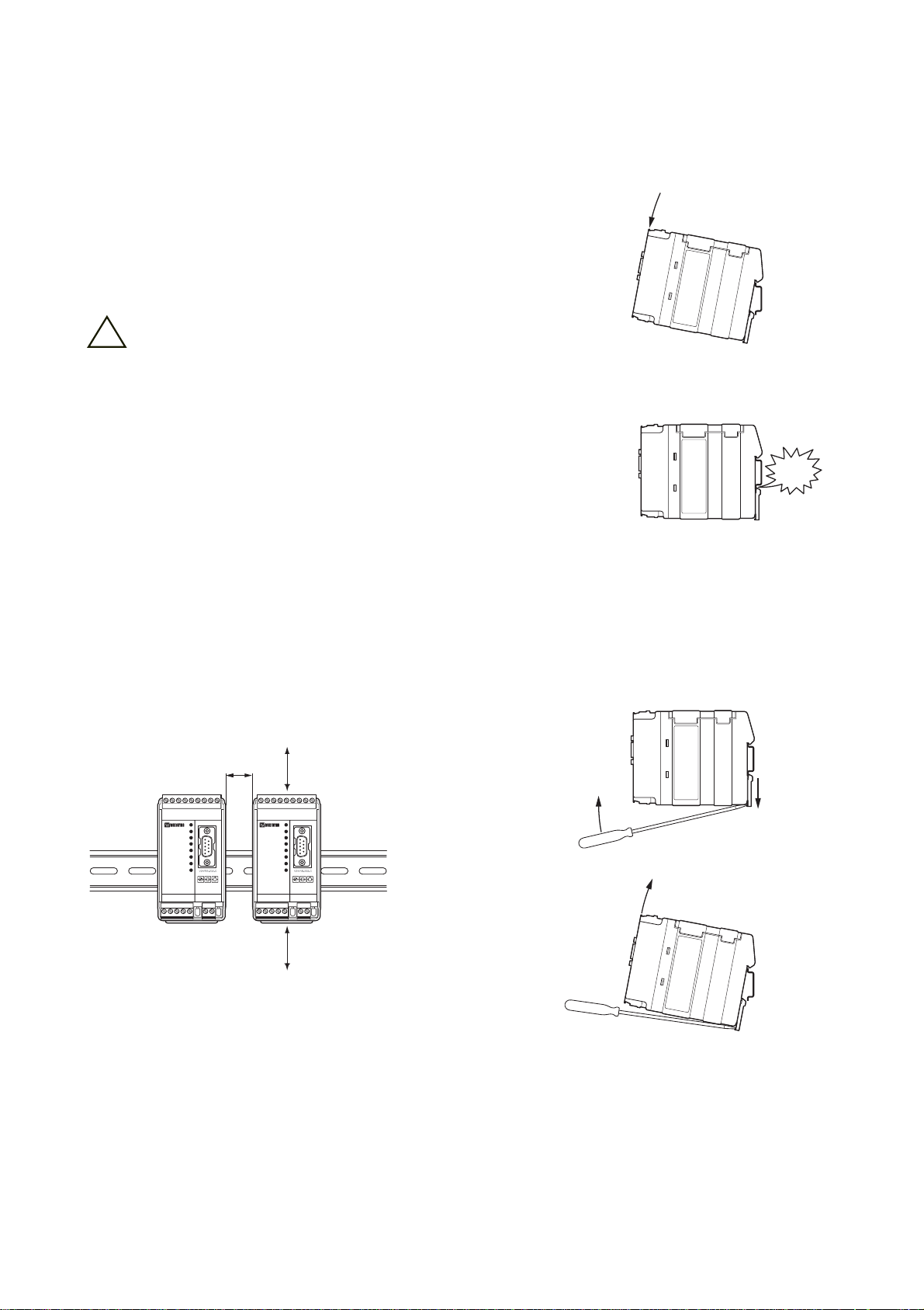
Mounting
This unit should be mounted on 35 mm DIN-rail which is horizontally mounted on a wall or
cabinet backplate.
This unit uses convection cooling.To avoid obstructing the airflow around the unit,
use the following spacing rules. Recommended spacing 25 mm (1.0 inch) above/below and 10
mm (0.4 inches) left/right the unit.
Snap on mounting, see figure
Removal
Press down the black support at the back of the unit using
a screwdriver, see figure.
10 mm *
(0.4 inches)
25 mm
25 mm
* Spacing (left/right) recommend-
ed for full operating temperature
range
!
CLICK!
Page 11

116610-2203
9-pos. D-sub
RS-232
Alarms
Leased
Line
Line
connection
RJ-11
Line
connection
422/485
Power
connection
LV/HV
9-pos. screw terminal
RS-232
5.2 Connections
TD-34 Tele Modem family consist of two products:TD-34 LV and TD-34 HV.
TD-34 LV has a 2-pos. power connector insensitive to polarity as shown by the symbol ≈ on
the front.
The PE wire “protective earth” is not connected internally in TD-34. but may be
connected for backwards compatibility.
Page 12

12 6610-2203
Direction 9-pos. Name Description
DCE-DTE D-sub
O 1 DCD Data Carrier Detect
O 2 RXD Receive Data
I 3 TXD Transmit Data
I 4 DTR Data Terminal Ready
– 5 SG Signal Ground
O 6 DSR Data Set Ready
I 7 RTS Request To Send
O 8 CTS Clear To Send
O 9 RI Ring Indicator
Direction 9-pos. Name Description
DCE-DTE screw terminal
– 1 SG Signal Ground
O 2 DSR Data Set Ready
I 3 DTR Data Terminal Ready
O 4 DCD Data Carrier Detect
O 5 CTS Clear To Send
I 6 RTS Request To Send
O 7 RXD Receive Data
I 8 TXD Transmit Data
– 9 RI Ring Indicator
5.2.1 Interface RS-232 9-pos D-sub
5.2.2 Interface RS-232, 9-pos screw terminal
5
4
3
2
1
9
8
7
6
987
6
543
2
1
Page 13
Direction 4-pos. Name Description
screw terminal
I/O 3 Tx+ (A/A’) Transmit (RS-422)
Transmit/Receive (RS-485)
I/O 4 Tx– (B/B’) Transmit (RS-422)
Transmit/Receive (RS-485)
I 1 Rx+ (A’) Receive (RS-422)
I 2 Rx– (B’) Receive (RS-422)
136610-2203
Direction Pos. no. Name Description
I/O 3 RING Transmit/Receive
I/O 4 TIP Transmit/Receive
I/O 2 RING* Transmit/Receive
I/O 5 TIP* Transmit/Receive
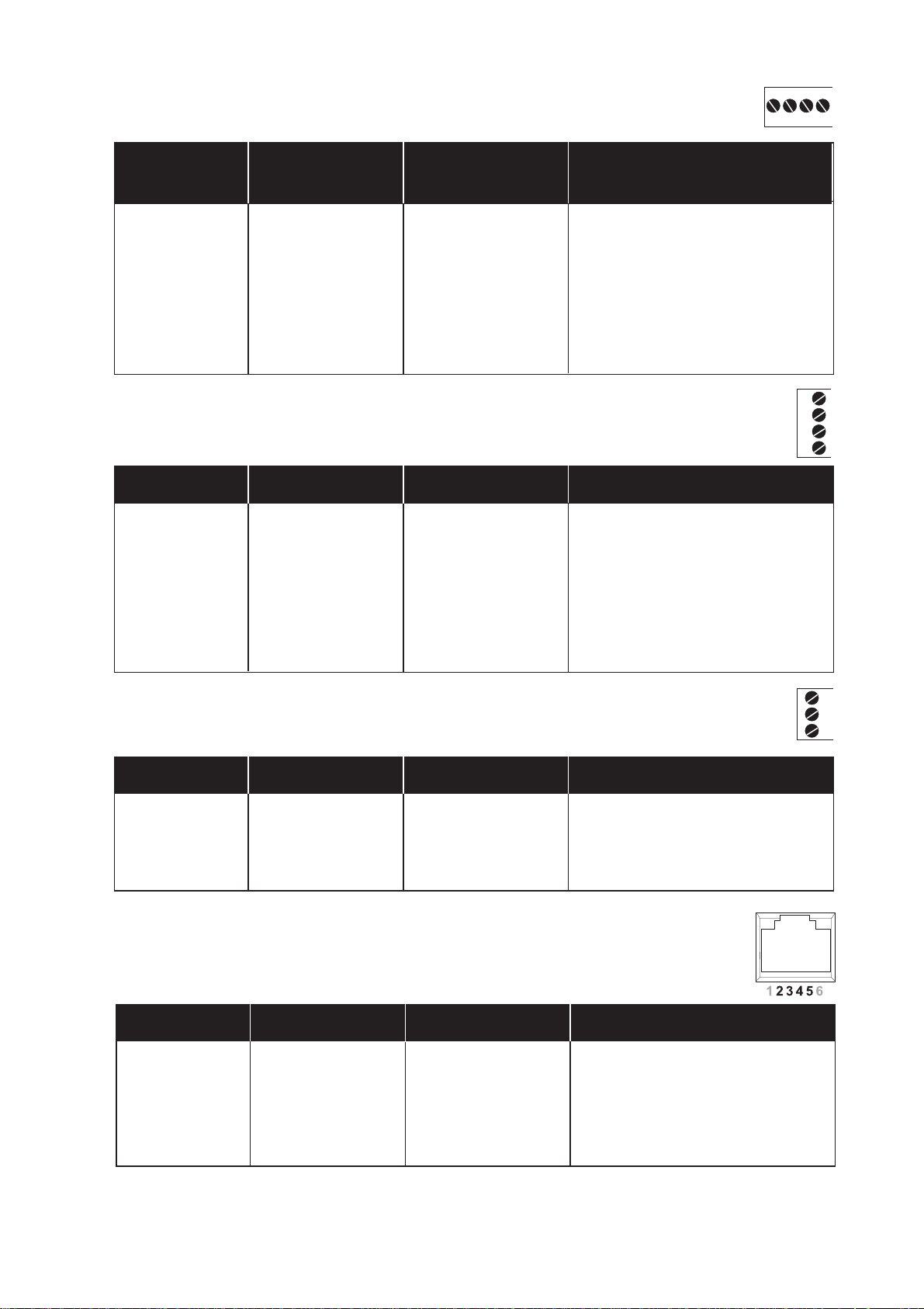
5.2.6 Interface RJ-11, PSTN
*) Modem is configurable by a DIP switch setting
Direction Pos. no. Name Description
O 1 LL1 Transmit (4-wire)
O 2 LL2 Transmit (4-wire)
I/O 3 LL3 Receive (4-wire)
Transmit/Receive (2-wire)
I/O 4 LL4 Receive (4-wire)
Transmit/Receive (2-wire)
5.2.4 Interface Leased Line
Direction Pos. no. Name Description
I 1 AL1 Alarm 1 Input
I 2 AL2 Alarm 2 Output
I 3 AL_COM Alarm Common
5.2.5 Interface Alarms
5.2.3 Interface RS-485/422, 4-pos screw terminal
3
2
1
12
3
4
4
3
2
1
Page 14

14 6610-2203
5.3 Configuration
TD-34 can be configured via AT-commands on the service interface, or by a remote modem (if
the TD-34 is set for remote configuration, see SW 4).
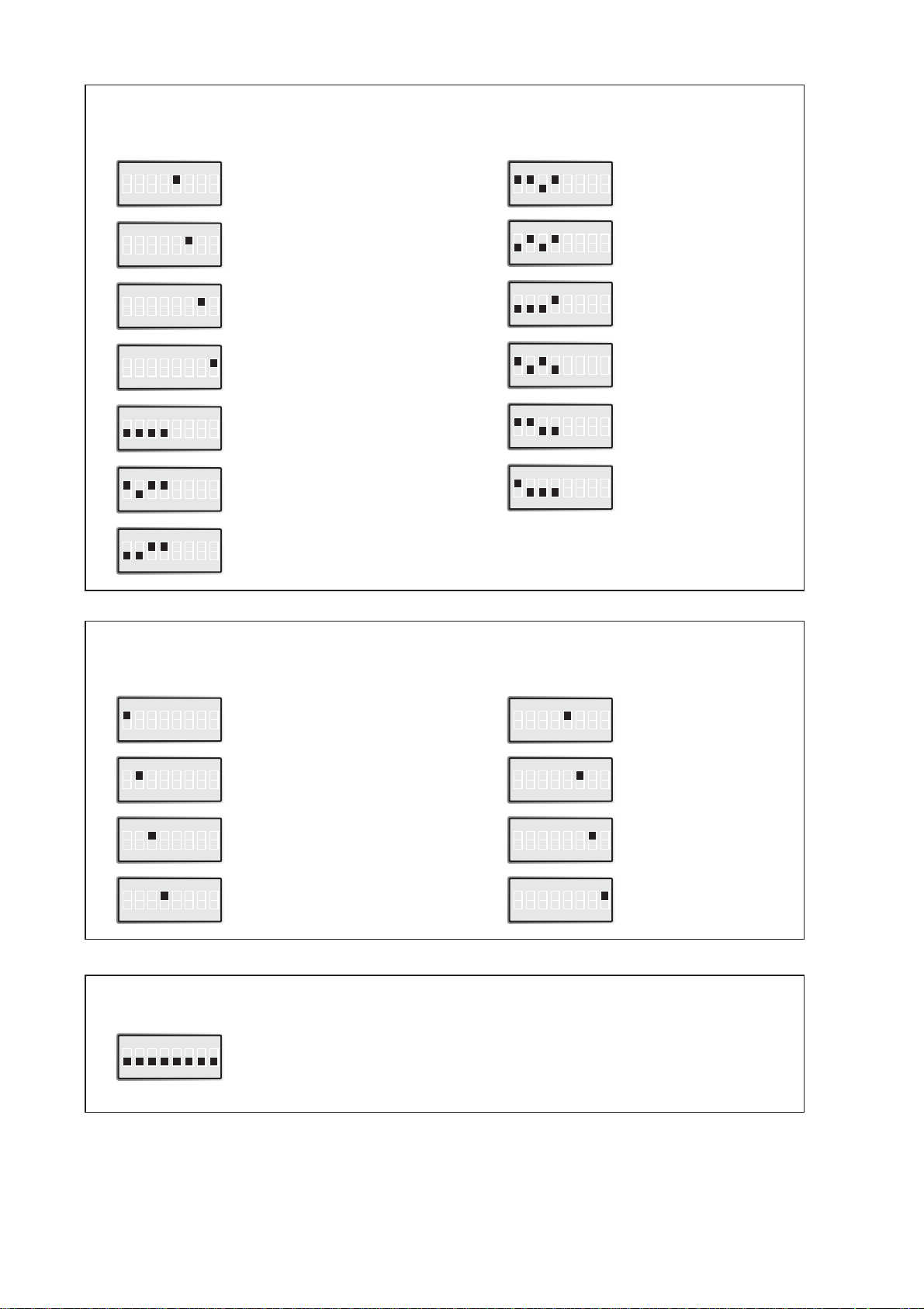
5.3.1 DIP-switch settings
DIP-switches are accessable under the lid on top/front of the unit. DIP-switches are
used to configure the unit.
Warning!
Prevent damage to internal electronics from electrostatic discharges (ESD) by
discharging your body to a grounding point (e.g. use of wrist strap), before the
lid on top/front of the unit is removed.
Warning! Do not open connected equipment.
Prevent access to hazardous voltages by disconnecting the unit from AC/DC mains
supply and all other electrical connections.
NOTE! The change of DIP-switch settings are valid only after a power on.
If configured by any other method during normal operation, this new
configuration override the DIP-switch settings. However, after a new
power on the DIP-switch settings have precedence.
!
!
Page 15

15
6610-2203
SW 1
DTE Speed and Formats
ON
12345678
ON
12345678
7E
ON
12345678
7O
ON
12345678
8N
ON
12345678
8E
ON
12345678
8O
ON
12345678
Direct Mode 8E or 8O
ON
12345678
Direct Mode 7E, 7O or 8N
ON
12345678
2 stop bits
ON
12345678
Auto detect
ON
12345678
300 bit/s
ON
12345678
600 bit/s
ON
12345678
1 200 bit/s
ON
12345678
2 400 bit/s
ON
12345678
4 800 bit/s
ON
12345678
9 600 bit/s
ON
12345678
19 200 bit/s
ON
12345678
38 400 bit/s
ON
12345678
57 600 bit/s
ON
12345678
115 200 bit/s
SW 2
RS-422/485 & Alarm Services
ON
12345678
Enable RS-485
ON
12345678
Enable RS-422
ON
12345678
Terminate
RS-422/485
ON
12345678
Enable I/O
7N
Page 16
16 6610-2203
SW 4
Special services
ON
12345678
Reliable mode disable \N0
ON
12345678
Remote configuration enable
ON
12345678
Dial-back PSTN enable
(2-wire leased line)
ON
12345678
Dial-back answer
ON
12345678
PLC mode enable
Q1E0&C1&K0&A1
ON
12345678
Abort disable
&A1
ON
12345678
Auto retrain disable
%E0
ON
12345678
Dial-back originate
SW 3
Line Mode & Modulation
ON
12345678
Leased line
(Dial-Up PSTN = Off)
ON
12345678
4-wire leased line mode
(2-wire leased line mode = Off)
ON
12345678
Leased line answer
(Originate = OFF)
ON
12345678
Not used
ON
12345678
Auto detect mode
ON
12345678
V.34, 33 600 bit/s
ON
12345678
V.34, 28 800 bit/s
ON
12345678
V.32, 9 600 bit/s
ON
12345678
V.32bis, 14 400 bit/s
ON
12345678
V.22bis, 2 400 bit/s
ON
12345678
V.22, 1 200 bit/s
ON
12345678
V.21, 300 bit/s
Factory settings
ON
12345678
SW1, SW2, SW3 and SW4
ON
12345678
V34, 19 200 bit/s
Page 17

176610-2203
5.4 LED Status Indicators
PWR Power Indication. Flashes if an error is detected
DTR Data Terminal Ready modem signal
RTS Request To Send modem signal
TD Transmitted Data: Displays data received from the local RS-232/V.24 port
RD Received Data: Displays data leaving the modem on the RS-232/V.24 port
DCD Data Carrier Detect modem signal
LINE Modem is off-hook. Flashes if the dial-back function is in use
AL1 Alarm input active
AL2 Alarm output active
Page 18

18 6610-2203
6. AT Commands
A – Answer
The modem will go off-hook and attempt to answer an incoming call if correct conditions are
met. Upon successful completion of answer handshake, the modem will go on-line in answer
mode.
The modem will enter the connect state after exchanging carrier with the remote modem.
If no carrier is detected within a period specified in register S7, the modem hangs up.
Any character entered during the connect sequence will abort the connection attempt.
Please also refer to AT&An
Syntax: ATA
Examples:
Result Codes: Please refer to Result codes (7)
&A – Ignore DTR character
The modem normally aborts the connection negotiation if a character is received from DTE
during the connection phase.This command gives the user the option to let the modem
ignore incoming characters.The parameter value, if valid, is written to S14 bit 4.
Syntax: AT&A<value>
<value> = 0 Enable abort (default)
= 1 Disable abort
Examples:
Result Codes: OK <value> = (0-1)
ERROR Otherwise
B – ITU-T or Bell
When the modem is configured to allow either option, the modem will select Bell or CCITT
modulation for a line speed connection of 300 or 1200 bit/s according to the parameter supplied.Any other line speed will use a CCITT modulation standard.The parameter value, if
valid, is written to S27 bit 6.
B0 Selects CCITT operation at 300 or 1200 bit/s during Call Establishment and a
subsequent connection. (Default)
B1 Selects BELL operation at 300 or 1200 bit/s during Call Establishment and a
subsequent connection.
\B – Transmit Break to Remote
In non-error correction mode, the modem will transmit a break signal to the remote modem
with a length in multiples of 100 ms according to parameter specified.
If a number in excess of 9 is entered, 9 is used.The command works in conjunction
with the \K command. In error correction mode, the modem will signal a break through the
active error correction protocol, giving no indication of the length.
\B1-\B9 Break length in 100 ms units. (Default = 3.) (Non-error corrected mode only.)
Page 19

196610-2203
%C – Enable/Disable Data Compression
Enables or disables data compression negotiation.The modem can only perform data
compression on an error corrected link.
Syntax: AT&%C<value>
<value> = 0 Disables data compression. Resets S46 bit 1
1 Enables MNP 5 data compression negotiation.
Resets S46 bit 1
2 Enables V.42 bis data compression. Sets S46 bit 1
3 Enables both V.42 bis and MNP 5 data
compression. Sets S46 bit 1. (Default)
&C – RLSD (DCD) control
The modem controls the RLSD output in accordance with the parameter supplied.
The parameter value, if valid, is written to S21 bit 5.
Syntax: AT&C<value>
<value> = 0 RLSD (DCD) remains ON at all times
= 1 RLSD (DCD) follows the state of the carrier (default)
Examples:
Result Codes: OK <value> = (0-1)
ERROR Otherwise
+CMGS – Send SMS message
This command send a SMS message to a specified number.
Syntax: AT+CMGS=<num>
AT+CMGS=?
<num> SMS message receiver number
Examples: AT+CMGS=12345
> 123
> ABC
CTRL^Z
OK
AT+CMGS=?
+CMGS : (0-16 CHAR)
OK
Result Codes: OK <num> = (0-16 CHAR)
ERROR Otherwise
Page 20

20 6610-2203
+CMGW – Store SMS in memory
This command sets SMS message and number in memory.
Syntax: AT+CMGW=<index>,<num>
AT+CMGW=?
AT+CMGW?
<index> Store SMS message in index [0,1]
<num> Store SMS number in index [0,1]
Examples: AT+CMGW=1,12345
> 123
> ABC
CTRL^Z
OK
AT+CMGW?
SMS NUM0=
SMS MSG0=
SMS NUM1=12345
SMS MSG1=123\rABC
OK
AT+CMGW=?
OK
Result Codes: OK <index>,<num> = (0-1), (0-16 CHAR)
ERROR Otherwise
+CMSS – Send SMS from memory
This command send a SMS message with number and data stored within memory.
Syntax: AT+CMSS=<index>,<num>
AT+CMSS=?
<index> Send SMS message from index [0,1]
<num> Send SMS with number instead of index [0,1] number
Examples: AT+CMSS=1
OK
AT+CMSS=1,123
OK
AT+CMSS=?
+CMSS : (0-1),(1-16 CHAR)
OK
Result Codes: OK <index>,<num> = (0-1), (0-16 CHAR)
ERROR Otherwise
Page 21

216610-2203
+CSCA – SMS provider and protocol
This command sets the provider and protocol parameters used for sending a SMS message.
Syntax: AT+CSCA=<provider>,<type>,<password>
AT+CSCA=?
AT+CSCA?
<provider> SMS service provider number
<type> SMS protocol type (0=NONE,1=UCP,2=TAP)
<password> SMS password (only for TAP protocol)
Examples: AT+CSCA=12345,1
OK
AT+CSCA?
+CSCA : PROVIDER=12345, PROTOCOL=UCP
OK
AT+CSCA=?
+CSCA : (0-16 CHAR), (0-2)
OK
Result Codes: OK <provider>,<type>,<password> = (0-16 CHAR),
(0-2), (0-8 CHAR)
ERROR Otherwise
+GCI – Country parameters
This extended syntax command selects and indicates the country of installation for the
modem.This parameter selects the settings for any operational parameters that need to
be adjusted for national regulations or telephone networks.
Syntax: AT+GCI=<value>
AT+GCI=?
AT+GCI?
<value> = B5 Selects country code for America.
= FD Selects country code for Europé.
Examples: AT+GCI=FD
OK
AT+GCI?
+GCI : FD
OK
AT+GCI= ?
+GCI : (B5,FD)
OK
Result Codes: OK <value> = (B5,FD)
ERROR Otherwise
Page 22

22 6610-2203
D – Dial
This command directs the modem to go on-line, dial according to the string entered and
attempt to establish a connection. If no dial string is supplied, the modem will go on-line and
attempt the handshake in originate mode.
NOTE:
If the ATD command is issued before the S1 register has cleared, the modem will respond
with the NO CARRIER result code.
The modem will behave as a data modem and will attempt to connect to another data
modem.The modem will have up to the period of time specified by register S6 to wait for
carrier and complete the handshake. If this time expires before the modem can complete the
handshake, the modem will go on-hook with the NO CARRIER response.This command will
be aborted in progress upon receipt of any DTE character before completion of the handshake.
Syntax: ATD<string>
<string>
Dial Modifiers
The valid dial string parameters are described below. Punctuation characters may be used
for clarity, with parenthesis, hyphen, and spaces being ignored.The valid dial string parameters are described below. Punctuation characters may be used for clarity, with parentheses, hyphen, and spaces being ignored.
0-9 DTMF digits 0 to 9.
* The ’star’ digit (tone dialing only).
# The ’gate’ digit (tone dialing only).
A-D DTMF digits A, B, C, and D. Some countries may prohibit sending of these
digits during dialing.
L Re-dial last number: the modem will re-dial the last valid telephone number.
The L must be immediately after the D with all the following characters
ignored).
R This command will be accepted, but not acted on.
S=n Dial the number stored in the directory (n = 0 to 3). (See &Z.)
! Flash: the modem will go on-hook for a time defined by the value of S29.
W Wait for dial tone: the modem will wait for dial tone before dialing the digits
following ”W“. If dial tone is not detected within the time specified by S6 or
S7, the modem will abort the rest of the sequence, return on-hook, and gen-
erate an error message.
@ Wait for silence: the modem will wait for at least 5 seconds of silence in the
call progress frequency band before continuing with the next dial string
parameter. If the modem does not detect these 5 seconds of silence before
the expiration of the call abort timer (S7), the modem will terminate the call
attempt with a NO ANSWER message. If busy detection is enabled, the
modem may terminate the call with the BUSY result code. If answer tone
arrives during execution of this parameter, the modem handshakes.
& Wait for credit card dialing tone before continuing with the dial string. If the
tone is not detected within the time specified by S6 or S7, the modem will
abort the rest of the sequence, return on-hook, and generate an error mes-
sage.
Page 23

236610-2203
, Dial pause: the modem will pause for a time specified by S8 before dialing the
digits following ”,”.
; Return to command state.Added to the end of a dial string, this causes the
modem to return to the command state after it processes the portion of the
dial string preceding the ”;”.This allows the user to issue additional AT commands while remaining off-hook.The additional AT commands may be placed
in the original command line following the ”;” and/or may be entered on subsequent command lines.The modem will enter call progress only after an
additional dial command is issued without the ”;” terminator. Use ”H” to
abort the dial in progress, and go back on-hook.
^ Toggles calling tone enable/disable: applicable to current dial attempt only.
( ) Ignored: may be used to format the dial string.
- Ignored: may be used to format the dial string.
<i> Invalid character: will be ignored.
<space> Ignored: may be used to format the dial string.
Examples:
Result Codes: Please refer to reference manual
&D – DTR control
This command interprets the ON to OFF transition of the DTR signal from the DTE in
accordance with the parameter supplied.The parameter value, if valid, is written to S21
bits 3 and 4.Also, see S25.
Syntax: AT&D<value>
<value> = 0 DTR drop is interpreted according to the setting as
follows: DTR is ignored (assumed ON).Allows operation with DTEs which do not provide DTR. (Default)
= 1 DTR drop is interpreted according to the setting as
follows: DTR drop is interpreted by the modem as if
the asynchronous escape sequence had been entered.
The modem returns to asynchronous command state
without disconnecting.
= 2 DTR drop is interpreted according to the setting as
follows: DTR drop causes the modem to hang up.
Auto-answer is inhibited.
= 3 DTR drop is interpreted according to the setting as
follows: DTR drop causes the modem to perform a
soft reset as if the Z command were received.The &Y
setting determines which profile is loaded.
Examples:
Result Codes: OK <value> = (0-3)
ERROR Otherwise
Page 24

24 6610-2203
E – Echo
The modem enables or disables the echo of characters to the DTE according to the
parameter supplied.The parameter value, if valid, is written to S14 bit 1.
Syntax: ATE<value>
<value> = 0 Disables command echo.
= 1 Enables command echo. (Default)
Examples:
Result Codes: OK <value> = (0-1)
ERROR Otherwise
%E – Enable/Disable Line Quality Monitor and Auto-Retrain or
Fallback/Fall Forward
Controls whether or not the modem will automatically monitor the line quality and request a
retrain (%E1) or fall back when line quality is insufficient or fall forward when line quality is
sufficient (%E2).The parameter value, if valid, is written to S41 bits 2 and 6.
If enabled, the modem attempts to retrain for a maximum of 30 seconds.
%E0 Disable line quality monitor and auto-retrain.
%E1 Enable line quality monitor and auto-retrain.
%E2 Enable line quality monitor and fallback/fall forward. (Default)
Fallback/Fall Forward.When %E2 is active, the modem monitors the line quality (EQM).When
line quality is insufficient, the modem will initiate a rate renegotiation to a lower speed within
the V.34/V.32 bis/V.32 (TD-33) modulation speeds. The modem will keep falling back within the
current modulation if necessary until the speed reaches 2 400 bit/s (V.34) or 4 800 bit/s (V.32).
Below this rate, the modem will only do retrains if EQM thresholds are exceeded. If the EQM
is sufficient for at least one minute, the modem will initiate a rate renegotiation to a higher
speed within the current modulation speeds.The rate renegotiation will be done without a
retrain if a V.32 bis connection is established.
Speeds attempted during fallback/fall forward are those shown to be available in the rate
sequences exchanged during the initial connection. Fallback/fall forward is available in error
correction and normal modes, but not in direct mode.
&F – Restore Factory Configuration (Profile)
The modem loads the factory default configuration (profile).The factory defaults are identified
for each command and in the S-Register descriptions.A configuration (profile) consists of a
subset of S-Registers.
Syntax: AT&F<value>
<value> = 0 Restore factory configuration 0.
= 1 Restore factory configuration 1
= 2 Restore Westermo extended configuration.
Examples:
Result Codes: OK <value> = (0-2)
ERROR Otherwise
Page 25

256610-2203
&G – Select Guard Tone
The modem generates the guard tone selected by this command according to the parameter
supplied (DPSK modulation modes only).The parameter value, if valid, is written to S23 bits 6
and 7.
&G0 Disables guard tone. (Default).
&G1 Disables guard tone.
&G2 Selects 1 800 Hz guard tone.
This command may not be permitted in some countries.
*G – Password control
This command controls whether or not the modem will handle Password and/or Call back
functionality.Value is written to S14 bit 6.
Syntax: AT*G<value>
<value> = 0 Disables password control (default)
= 1 Enables password control
Examples:
Result Codes: OK <value> = (0-1)
ERROR Otherwise
H – Hangup
This command initiates a hang up sequence.
Syntax: ATH<value>
<value> = 0 The modem will release the line if the modem is cur-
rently on-line. Country specific, modulation specific,
and error correction protocol specific (S38) processing
is handled outside of the H0 command.
= 1 If on-hook go off-hook for S7 time.
Examples:
Result Codes: OK <value> = (0-1)
ERROR Otherwise
I – Information
This command causes the modem to report the requested result according to the command
parameter.
Syntax: ATI<value>
<value> = 0-7 Please refer to reference manual
= 8 Switch settings
= 9 Software version numbers (MCU and CS)
Examples: ATI8
000 000 000 000
OK
ATI9
4100-8050
4100-8040
OK
Result Codes: OK <value> = (0-9)
ERROR Otherwise
Page 26

26 6610-2203
+ICF – Fixed DTE format
This command specifies the data format between the DTE and the modem.
Syntax: AT+ICF=<value>
AT+ICF=?
AT+ICF?
<value> Format (0-5,8-13)
Format:
Auto 7N2 7E1 7O1 8N1 8E1 8O1 7E2 7O2 8N2 8E2 8O2
Value: 0 4,4 5,1 5,0 3,4 2,1 2,0 4,1 4,2 1,4 1,1 1,2
Examples: AT+ICF=3
OK
AT+ ICF?
+ ICF : (3,4)
OK
AT+ ICF =?
+ ICF : (0-5),(8-13)
OK
Result Codes: OK<value> = (0-5),(8-13)
ERROR Otherwise
+IPR – Fixed DTE baud rate
This command specifies the data rate between the DTE and the modem.
Syntax: AT+IPR=<value>
AT+IPR=?
AT+IPR?
<value> Baud rate (300–230400)
Baud: 300, 600, 1200, 2400, 4800, 7200, 9600, 14400, 19200, 28800, 38400,
57600, 115200, 230400
0 (will give auto selection)
Examples: AT+IPR=9600
OK
AT+IPR?
+IPR : 9600
OK
AT+IPR=?
+IPR : (0, 300, 600, 1200, 2400, 4800, 7200, 9600, 19200, 28800, 38400,
57600, 115200, 230400)
OK
Result Codes: OK <value> = (0, 300–230400)
ERROR Otherwise
Page 27

276610-2203
\K – Break Control
Controls the response of the modem to a break received from the DTE or the remote
modem or the \B command according to the parameter supplied.The parameter value, if valid,
is written to S40 bits 3, 4, and 5.
The response is different in three separate states.
The first state is where the modem receives a break from the DTE when the modem is operating in data transfer mode:
\K0 Enter on-line command mode, no break sent to the remote modem.
\K1 Clear data buffers and send break to remote modem.
\K2 Same as 0.
\K3 Send break to remote modem immediately.
\K4 Same as 0.
\K5 Send break to remote modem in sequence with transmitted data. (Default)
The second case is where the modem is in the on-line command state
(waiting for AT commands) during a data connection,
and the \B is received in order to send a break to the remote modem:
\K0 Clear data buffers and send break to remote modem.
\K1 Clear data buffers and send break to remote modem. (Same as 0.)
\K2 Send break to remote modem immediately.
\K3 Send break to remote modem immediately. (Same as 2.)
\K4 Send break to remote modem in sequence with data.
\K5 Send break to remote modem in sequence with data. (Same as 4.) (Default)
The third case is where a break is received from a remote modem during a non-error
corrected connection:
\K0 Clears data buffers and sends break to the DTE.
\K1 Clears data buffers and sends break to the DTE. (Same as 0.)
\K2 Send a break immediately to DTE.
\K3 Send a break immediately to DTE. (Same as 2.)
\K4 Send a break in sequence with received data to DTE.
\K5 Send a break in sequence with received data to DTE. (Same as 4.) (Default)
&K – Flow Control
Defines the DTE/DCE Flow Control.The parameter is written to S39 bits 0,1, and 2.
&K0 Disables flow control (Default).
&K3 Enables RTS/CTS.
&K4 Enables XON/XOFF.
&K5 Enables transparent XON/XOFF.
-K – MNP Extended Services
Enables or disables conversion of a V.42 LAPM connection to an MNP 10 connection.
The parameter value, if valid, is written to S40 bits 0 and 1.
-K0 Disables V.42 LAPM to MNP 10 conversion. (Default)
-K1 Enables V.42 LAPM to MNP 10 conversion.
-K2 Enables V.42 LAPM to MNP 10 conversion; inhibits MNP Extended Services initiation
during V.42 LAPM answer mode detection phase.
Page 28

28 6610-2203
%L – Report Line Signal Level
Returns a value which indicates the received signal level.The value returned is a direct
indication of the receive level at the MDP, not at the telephone line connector.
For example, 009 = –9 dBm, 043 = –43 dBm, and so on.
L – Speaker Volume
Sets the speaker volume control.The parameter is written to S22 bits 0 and 1.
L0 Low Volume
L1 Low Volume (Default)
L2 Medium Volume.
L3 High Volume.
*L – Display Stored Passwords and Callback numbers
This commands displays stored Password and Callback numbers.
M – Speaker Control
Speaker Control command.The parameter is written to S22 bits 2 and 3.
M0 Speaker is always off
M1 Speaker is on during call establishment, but off when receiving a carrier. (Default)
M2 Speaker is always on.
M3 Speaker is off when receiving a carrier and during dialing, but on during answering.
Page 29

296610-2203
+MS – Select Modulation
This extended-format command selects the modulation and, optionally, enables or disables
automode, specifies the lowest and highest receive rates, and, specifies the highest transmit
rate using one to six subparameters.The command format is:
+MS=<carrier>,<automode>,<min_tx_rate>,<max_tx_rate>,<min_rx_rate>,<max_rx_rate>
Where
<carrier> = A string which specifies the preferred modulation (automode enabled) or the
modulation (automode disabled) to use in originating or answering a connection.The options
are:
<carrier> Modulation Possible Rates (bit/s)
V21 V.21 300
V22 V.22 1 200
V22B V.22 bis 2 400 or 1 200
V23C V.23 1 200
V32 V.32 9 600 or 4 800
V32B V.32 bis 14 400, 12 000, 9 600, 7 200, or 4 800
V34 V.34 33 600, 31 200, 28 800, 26 400, 24 000, 21 600, 19 200, 16 800, 14 400,
12 000, 9 600, 7 200, 4 800, or 2 400
B103 Bell 103 300
B212 Bell 212 1 200
<automode>
0 disable
1 enable
<min_xx_rate>, <max_xx_rate>
Min and max data rates depending on modulation used (see below).
Reporting Supported Options
The modem can send a string of information to the DTE consisting of supported options
using the following command:
+MS=?
or
For listing current configuration:
+MS?
Page 30

30 6610-2203
\N – Operating Mode
This command controls the preferred error correcting mode to be negotiated in a
subsequent data connection.
\N0 Selects normal speed buffered mode (disables error-correction mode). (Forces &Q6.)
\N1 Serial interface selected – Selects direct mode and is equivalent to &Q0 mode of
operation. (Forces &Q0.)
\N2 Selects reliable (error-correction) mode. The modem will first attempt a LAPM
connection and then an MNP connection. Failure to make a reliable connection
results in the modem hanging up. (Forces &Q5, S36=4, and S48=7.)
\N3 Selects auto reliable mode.This operates the same as \N2 except failure to make a
reliable connection results in the modem falling back to the speed buffered normal
mode. (Forces &Q5, S36=7, and S48=7.)
\N4 Selects LAPM error-correction mode. Failure to make an LAPM error-correction
connection results in the modem hanging up. (Forces &Q5 and S48=0.)
Note:The -K1 command can override the \N4 command.
\N5 Selects MNP error-correction mode. Failure to make an MNP error-correction
connection results in the modem hanging up. (Forces &Q5, S36=4, and S48=128.)
O – Online
This command determines how the modem will enter the on-line data mode. If the modem is
in the on-line command mode, it enters the on-line data mode with or without a retrain.
If the modem is in the off-line command mode (no connection), ERROR is reported.
Syntax: ATO<value>
<value> = 0 Enters on-line mode without retrain (Default)
= 1 Enters on-line mode with retrain
Examples:
Result Codes: OK <value> = (0-1)
ERROR Otherwise
*P – Store Password and Callback number
It is possible to store 2 different Passwords and Callback numbers in the modem.
This command works if command *G1 is used.
The command format is:
*P0:Password#0:Callbacknumber#0
*P1:Password#1:Callbacknumber#1
Password min. 6 characters max. 12 characters.
Callback number up to 18 characters.
If Password and Callback number is stored then the modem prompts the text ”PASSWORD:”
before releasing the connection and dialing back after a time given in S13.
If target is busy three retries will be executed.
If no Callback number is stored then the modem prompts the text ”PASSWORD:”
before switching into normal data transmission mode.
If no Password is stored then the modem prompts ”CALLBACK NUMBER:” before releasing
the connection and dialing back after a time given in S13.
Page 31

316610-2203
Q – Quiet
The command enables or disables the sending of result codes to the DTE according to the
parameter supplied.The parameter value, if valid, is written to S14 bit 2.
Syntax: ATQ<value>
<value> = 0 Quiet mode OFF (default)
= 1 Quiet mode ON
Examples:
Result Codes: OK <value> = (0-1)
ERROR Otherwise
&Q – Async Mode
This command is used to control the connection modes permitted. It is used in conjunction
with S36 and S48. (Also, see \N).
&Q0 Selects direct asynchronous operation.The value 000b is written to S27 bits 3, 1,
and 0, respectively.
&Q5 The modem will try to negotiate an error-corrected link.The modem can be config-
ured using S36 to determine whether a failure will result in the modem returning
on hook or will result in fallback to an asynchronous connection.The value 101b
is written to S27 bits 3, 1 and 0 respectively (Default).
&Q6 Selects asynchronous operation in normal mode (speed buffering).The value 110b
is written to S27 bits 3, 1 and 0, respectively.
%Q – Report Line Signal Quality
Reports the line signal quality. Returns the higher order byte of the EQM value. Based on the
EQM value, retrain or fallback/fall forward may be initiated if enabled by %E1 or %E2.
S – S-Register
Syntax: ATS<value>[<=num> | <?>]
<value> Register
<=num> Set value num
<?> Return register
Examples:
Result Codes: Please refer to Results ()
&S – DSR Override
This command selects how the modem will control DSR.The parameter value, if valid,
is written to S21 bit 6.
&S0 DSR will remain ON at all times. (Default)
&S1 DSR will become active after answer tone has been detected and inactive
after the carrier has been lost.
Page 32

32 6610-2203
V – Result format
This command selects the sending of short-form or long-form result codes to the DTE.
The parameter, if valid, is written to S14 bit 3.
Syntax: ATV<value>
<value> = 0 Short form result codes
= 1 Long form result codes (default)
Examples:
Result Codes: OK <value> = (0-1)
ERROR Otherwise
\V – Single Line Connect Message Enable
This command enables or disables the single line connect message format as follows:
\V0 Connect messages are controlled by the command settings X,W, and S95. (Default)
\V1 Connect messages are displayed in the single line format described below subject to
the command settings V (Verbose) and Q (Quiet). In Non-Verbose mode (V0), single
line connect messages are disabled and a single numeric result code is generated for
CONNECT DTE.
When single line connect messages are enabled, there are no CARRIER, PROTOCOL,
or COMPRESSION messages apart from the fields described below.
The single line connect message format is:
CONNECT
<DTE Speed></Modulation></Protocol></Compression></Line
Speed>/<Voice and Data>
Where:
<DTE Speed> = DTE speed, e.g., 57 600.
Modulation = “V34” for V.34 modulation.
“V32” for V.32 or V.32bis modulation.
Note: Modulation is omitted for all other modulations.
Protocol = “NONE” for no protocol.
“ALT” for Microcom Network Protocol.
“LAPM” for LAP-M protocol.
Compression = “CLASS5” for Microcom MNP5 compression.
“V42BIS” for V.42bis compression.
Note: Compression is omitted if protocol is NONE.
Line Speed = Asymmetric rates are displayed as /rate:TX/rate:RX, e.g., /1 200
TX/75 RX.
Symmetric rates are displayed as a single DCE rate, e.g., 14 400.
Voice and Data = Blank for Data mode only.
LAPM-SREJ = Selective reject.
Page 33

336610-2203
&V – System settings/statistics
&V0 – Display Current Configuration and Stored Profiles Reports the current (active)
configuration, the stored (user) profiles, and the first four stored telephone numbers.
The stored profiles and telephone numbers are not displayed if the NVRAM is not
operational as detected by the NVRAM test during reset processing.
ACTIVE PROFILE:
B0 E1 L1 M1 N1 QO T V1 W0 X4 Y0 &C0 &D0 &G2 &K3 &Q5 &R1 &S0 &T4
&X0 &Y0 S00:002 S01:000 S02:043 S03:013 S04:010 S05:008 S06:002 S07:030
S08:002 S09:006 S10:014 S11:255 S12:050 S18:000 S25:005 S26:001 S36:007
S37:000 S38:020 S46:138 S48:007 S95:000
STORED PROFILE 0:
B0 E1 L1 M1 N1 QO T V1 W0 X4 Y0 &C0 &D0 &G2 &K3 &Q5 &R1 &S0 &T4
&X0 S00:002 S02:043 S06:002 S07:030 S08:002 S09:006 S10:014 S11:095 S12:050
S18:000 S36:007 S37:000 S40:105 S41:003 S46:138 S95:000
STORED PROFILE 1:
B0 E1 L1 M1 N1 QO T V1 W0 X4 Y0 &C0 &D0 &G2 &K3 &Q5 &R1 &S0 &T4
&X0 S00:002 S02:043 S06:002 S07:030 S08:002 S09:006 S10:014 S11:095 S12:050
S18:000 S36:007 S37:000 S40:105 S41:003 S46:138 S95:000
TELEPHONE NUMBERS:
0 = 1 =
&V1 – Displays the last connection statistics in the following format
(shown with typical results):
TERMINATION REASON..........................LOCAL REQUEST
LAST TX rate
....................................33 600 BIT/S
HIGHEST TX rate
...............................33 600 BIT/S
LAST RX rate
....................................33 600 BIT/S
HIGHEST RX rate
...............................33 600 BIT/S
PROTOCOL
...........................................LAPM
COMPRESSION
......................................V42Bis
Line QUALITY
....................................033
Rx LEVEL
...........................................015
Highest Rx State
.............................67
Highest TX State
.............................67
EQM Sum
.............................................00C2
RBS Pattern
......................................FF
Rate Drop
.........................................FF
Digital Pad
......................................None
Local Rtrn Count
.............................00
Remote Rtrn Count
...........................00
Flex fail
RBS Pattern: Shows the number of least significant bits robbed per 6 bytes.
Digital Pad: Shows if a pad was encountered and if so, what was the digital loss.
Flex: Shows V.8bis information as follows:
First byte: Octet 13 (second byte of manufacturer id, 94 = K56flex)
Second byte: Octet 14 (Licensee code: 81 = Rockwell)
Third byte: Octet 15 (manufacturer's product capabilities)
Fourth byte: Octet 16 (K56flex version number)
Fifth byte: Octet 17 (Rockwell pump code version number)
Sixth byte: Octet 18 (x-law and controller version number)
Bit 4: 0 Controller version
Syntax: AT&V<value>
<value> = 0 System settings
= 1 Last connection statistics
Examples:
Result Codes: OK <value> = (0-1)
ERROR Otherwise
Page 34

34 6610-2203
W – Connect Message Control
This command controls the format of CONNECT messages.The parameter value, if valid, is
written to S31 bits 2 and 3.
W0 Upon connection, the modem reports only the DTE speed (e.g., CONNECT 19 200).
Subsequent responses are disabled. (Default)
W1 Upon connection, the modem reports the line speed, the error correction protocol,
and the DTE speed, respectively. Subsequent responses are disabled.
W2 Upon connection, the modem reports the DCE speed (e.g., CONNECT 14 400).
Subsequent responses are disabled.
&W – Store system settings
Saves the current (active) configuration (profile), including S-Registers, in one of the two user
profiles in NVRAM as denoted by the parameter value.This command will yield an ERROR
message if the NVRAM is not operational as detected by the NVRAM test.
The current configuration is comprised of a list of storable parameters illustrated in the
&V command.These settings are restored to the active configuration upon receiving an
Zn command or at power up (see &Yn command).
Syntax: AT&W<value>
<value> = 0 Store the current configuration as profile 0.
= 1 Store the current configuration as profile 1.
Examples:
Result Codes: OK <value> = (0-1)
ERROR Otherwise
Page 35

356610-2203
*WCID – Caller ID / A-Number
This command set and display Caller ID parameters and data.
In Caller ID mode 3 and 4 the modem will wait for incoming call and then display the incoming number as a format or unformat string. In Caller ID mode 5 the modem will wait for
incoming call and if the number match the A-Number stored in the modem, the modem will
answer the call.
Syntax: AT*WCID
AT*WCID=<mode>,<num>
AT*WCID=?
AT*WCID?
<mode> = 0 Disabled
= 1 CID format after ring signal (not supported)
= 2 CID unformat after ring signal (not supported)
= 3 CID format before ring signal
= 4 CID unformat before ring signal
= 5 A-Number to answer
<num> A-Number (16 char)
Examples: AT*WCID=1
OK
AT*WCID (After RING)
CALLER ID : 12345
OK
AT*WCID=5,12345 (Modem will answer if incoming number is 12345)
OK
AT*WCID=?
*WCID : MODE=5, ANUM=12345
OK
AT*WCID=?
*WCID: (0-5),(0-16 CHAR)
OK
Result Codes: OK <mode>,<num>=(0-5),(0-16 Characters)
ERROR Otherwise
Page 36

36 6610-2203
*WDB – Dialback
This command set and display the dialback parameters and data.
When the dialback function is configured and enabled the 2-wired leased line will have a PSTN
backup line. If the leased line connection is lost, the modem will try (number of retries) to
reconnect before it will try to connect (to the number specified) on the PSTN line. If the
reconnect time is set and the backup line is used, the modem will close the PSTN connection
after the specified number of minutes and then try to connect on the 2-wired leased line.
Syntax: AT*WDB=<num>,<retries>,<time>
AT*WDB=?
AT*WDB?
<num> Dialback number string (max 16 chars)
< retries > Number of connect fails (0-9, 3 Default)
< time > Time before reconnect (0-255, 0 Default = OFF)
Examples: AT*WDB =12345,3,1
OK
AT*WDB ?
*WDB: NUMBER=12345, RETRIES=3, TIME=1
OK
AT*WDB =?
*WDB: (0-16 CHAR),(0-9),(0-255)
OK
Result Codes: OK <num>,<retries>,<time>=(0-16 Characters),(0-9).(0-255)
ERROR Otherwise
Page 37

376610-2203
*WIO – General IO list
This command handle the alarm IO (input and output).
Syntax: AT*WIO=<value>
AT*WIO=?
AT*WIO?
AT*WIO!
<value> IO output relay state (0=OPEN, 1=SHORT)
Examples: AT*WIO=0
OK
AT*WIO?
*WIO : IN=0, OUT=0
OK
AT*WIO=?
*WIO: (0,1)
OK
AT*WIO!
IO TEST ('?' FOR HELP)
? - HELP
+/- - INC/DEC PULSE (10 MS)
H - SET OUTPUT HIGH
L - SET OUTPUT LOW
S - START/STOP PULSES
1..9 - PULSE BURST
V - VIEW IO DATA
Q - QUIT TEST
OK
Result Codes: OK <value> = (0,1)
ERROR Otherwise
Page 38

38 6610-2203
*WIOL – General IO list
This command set IO list entries with parameters and data.
Syntax:
AT*WIOL=<entry>,<service>,<flag>,<timeout>,<priority>,<data1>,<data2>
AT*WIOL=?
AT*WIOL?
<entry> IO entry number
<service> IO entry service(0=NONE, 1=DIAL, 2=SMS, 3=TEXT,
4=EMAIL, 5=OUT, 6=CMD, 7=TRANS)
<flag> IO retry
(0=NO, 1=RETRY, 2=RETRY_3, 3=NEXT_OK,
4=NEXT_ERR)
<timeout> IO timeout (0=NO, 1-255=MINUTES)
<priority> IO timeout (0=NO, 1=PRIORITY)
<data1> IO entry data field 1
<data2> IO entry data field 2
Examples: AT*WIOL =1,2,2,0,12345,ABCDEFG
OK
AT*WIOL?
# SERVICE FLAG TIME PRI DATA1 DATA2
1 DIAL NO 000 0 12345
2 SMS RETRY_3 000 1 12345
3 NONE NO 000 0
4 NONE NO 000 0
5 NONE NO 000 0
6 NONE NO 000 0
7 TEXT RETRY 005 1 123 ABC
8 NONE NO 000 0
OK
AT*WIOL=?
*WIOL : (1-8),(0-7),(0-4),(0-255),(0,1),(0-16 CHAR), (0-40 CHAR),
OK
Result Codes: OK <entry>,<service>,<flag>,<timeout>,<priority>,
<data1>,<data2> =(1-8),(0-7),(0-4),(0-255),(0,1),
(0-16 Characters) ,(0-40 Characters)
ERROR Otherwise
Page 39

396610-2203
*WIOD – General IO delete entry
This command delete an IO entry in the list.
Syntax: AT*WIOD=<index>[,<start,stop>]
AT*WIOD=?
<index> IO entry index
[,<start,stop>] IO entry start,stop index
Examples: AT*WIOD=2
OK
AT*WIOD=3,7
OK
AT*WIOD=?
*WIO: (1-8)[,(1-8)]
OK
Result Codes: OK <index>[,<start,stop>] = (1-8)[ (1-8,1-8)]
ERROR Otherwise
*WIOP – General IO parameters
This command set the IO parameters.
Syntax: AT*WIOP=<t0>,<t1>,<type>,<trig>,<norm>
AT*WIOP=?
AT*WIOP?
<t0> Min trig pulse time in 10 ms [0-255]
<t1> Max trig pulse time in 10 ms [0-255]
<type> Trig pulse type [0=NO, 1=LEVEL, 2=PULSE]
<trig> Pulse trig type [0=NO, 1=HIGH, 2=LOW, 3=POS, 4=NEG]
<norm> Normaly [0=NO, 1=OPEN, 2=SHORT, 3=DCD, 4=DTR]
Examples: AT*WIOP=5,10,1,1,3
OK
AT*WIOP=,,2,,
OK
AT*WIOP?
*WIO :TMIN=5,TMAX= 10, TYPE=2,TRIG=1, NORM=3
OK
Result Codes: OK <t0>,<t1>,<type>,<trig>,<norm> = (0-255), (1-255), (0-2),
(0-4), (0-4)
ERROR Otherwise:
*WRAE – End remote access
This command end the remote access session.
Syntax: AT*WRAE
Examples:
Result Codes: OK
Page 40

40 6610-2203
*WRAP – Remote access password
This command set the remote access password.
Syntax: AT*WRAP=<password>
AT*WRAP=?
AT*WRAP?
<password> Remote access password (6-16 char:s)
Examples: AT*WRAP=QWERTY
OK
AT*WRAP=?
*WRAP : (6-12 CHAR)
OK
Result Codes: OK <password>=(6-12 Characters)
ERROR Otherwise
*WSYNC – LL synch parameters
This command set the leased line synchronization timeout parameters.
Syntax: AT*WSYNC=<dial>,<ans>,<sync>
AT*WSYNC=?
AT*WSYNC?
<dial> LL sync dial timeout (0-255) in seconds
<ans> LL sync ans timeout (0-255) in seconds
<sync> LL sync timeout (0-255) in seconds
Examples: AT*WSYNC=50,50,50
OK
Result Codes: OK <dial>,<ans>,<sync> = (0-255), (0-255), (0-255)
ERROR Otherwise
Page 41

416610-2203
X – Extended Result Codes
This command selects which subset of the result messages will be used by the modem to
inform the DTE of the results of commands.
Blind dialing is enabled or disabled by country parameters. If the user wishes to enforce dial
tone detection, a "W" can be placed in the dial string (see D command). Note that the information below is based upon the default implementation of the X results table.
X0 Disables monitoring of busy tones unless forced otherwise by country requirements;
send only OK, CONNECT, RING, NO CARRIER, ERROR, and NO ANSWER result
codes. Blind dialing is enabled/disabled by country parameters. If busy tone detection
is enforced and busy tone is detected, NO CARRIER will be reported. If dial tone
detection is enforced or selected and dial tone is not detected, NO CARRIER will be
reported instead of NO DIAL TONE.The value 000b is written to S22 bits 6, 5, and 4,
respectively.
X1 Disables monitoring of busy tones unless forced otherwise by country requirements;
send only OK, CONNECT, RING, NO CARRIER, ERROR, NO ANSWER, and
CONNECT XXXX (XXXX = rate). Blind dialing enabled/disabled by country parameters. If busy tone detection is enforced and busy tone is detected, NO CARRIER will
be reported instead of BUSY. If dial tone detection is enforced or selected and dial
tone is not detected, NO CARRIER will be reported instead of NO DIAL TONE.
The value 100b is written to S22 bits 6, 5, and 4, respectively.
X2 Disables monitoring of busy tones unless forced otherwise by country requirements;
send only OK, CONNECT, RING, NO CARRIER, ERROR, NO DIALTONE, NO
ANSWER, and CONNECT XXXX. If busy tone detection is enforced and busy tone
is detected, NO CARRIER will be reported instead of BUSY. If dial tone detection is
enforced or selected and dial tone is not detected, NO DIAL TONE will be reported
instead of NO CARRIER.The value 101b is written to S22 bits 6, 5, and 4, respectively.
X3 Enables monitoring of busy tones; send only OK, CONNECT, RING, NO CARRIER,
ERROR, NO ANSWER, and CONNECT XXXX. Blind dialing is enabled/disabled by
country parameters. If dial tone detection is enforced and dial tone is not detected,
NO CARRIER will be reported.The value 110b is written to S22 bits 6, 5, and 4,
respectively.
X4 Enables monitoring of busy tones; send all messages.The value 111b is written to S22
bits 6, 5, and 4, respectively. (Default)
Page 42

42 6610-2203
Y – Long Space Disconnect
This command enables/disables the generation and response to long space disconnect.
The parameter value, if valid, is written to S21 bit 7.
Y0 Disables long space disconnect. (Default)
Y1 Enables long space disconnect. In non-error correction mode, the modem will send
a long space of four seconds prior to going on-hook. In non-error correction mode,
the modem will respond to the receipt of a long space (i.e., a break signal greater
than 1.6 seconds) by going on-hook.
&Y – Designate a Default Reset Profile
This command selects which user profile will be used after a hard reset.
&Y0 The modem will use profile 0.
&Y1 The modem will use profile 1.
Z – Software reset
The modem performs a soft reset and restores (recalls) the configuration profile according to
the parameter supplied. If no parameter is specified, zero is assumed.
Syntax: ATZ<value>
<value> = 0 Soft reset, profile 0
= 1 Soft reset, profile 1
Examples:
Result Codes: OK <value> = (0-1)
ERROR Otherwise
&Z=x – Store Telephone Number
The modem can store up to two telephone numbers and each telephone number dial string
can contain up to 34 digits.
&Zn=x n = 0 to 1 and x = dial string.
Page 43

436610-2203
7. Result Codes
0 OK A command line has been executed.
1 CONNECT For X command values specifying no speed reporting, the modem has connected to the line and
either the line speed is 300 bit/s and line speed is enabled, or the DTE speed is 300 bit/s and DTE speed report-
ing is enabled.
2 RING An incoming ring signal is detected on the line.
3 NO CARRIER Sent when attempting to establish a call if:
1. Ringback is detected and later ceases but no carrier is detected within the period of time determined by register S7, or
2. No ringback is detected within the period of time determined by register S7.
Also sent when the modem auto-disconnects due to loss of carrier.
For X0, sent for the following conditions:
1. If busy tone detection is enforced, busy or circuit busy has been detected.
2. If dial tone detection is enforced or selected, dial tone has not been detected.
4 ERROR Sent during an attempt to execute a command line if any of the following conditions occur:
1.The command line contains a syntax error.
2.The modem cannot execute a command contained in the command line, i.e., the command does
not exist or is not supported.
3.A command parameter within the command line is outside the permitted range.
For X0, X1, X2, and X3, this message is sent instead of DELAYED and BLACKLISTED.
5 CONNECT 1 200 The modem has connected to the line and either the line speed is 1 200 bit/s and DCE speed
reporting is enabled, or the DTE speed is 1 200 bit/s and DTE speed reporting is enabled.
6 NO DIALTONE For X2 and X4, the modem has been instructed to wait for dial tone during dialing but none is
received.
7 BUSY For X3 and X4, if busy tone detection is enforced, the busy (engaged) signal is detected on the line when
the modem is attempting to originate a call.
8 NO ANSWER The modem is attempting to originate a call if a continuous ringback signal is detected on the line
until the expiration of the timer S7.
9 CONNECT 0600 The modem has connected to the line, the DTE speed is 600 bit/s, and DTE speed reporting
is enabled.
10 CONNECT 2 400 The modem has connected to the line and either the line speed is 2 400 bit/s and DCE
speed reporting is enabled, or the DTE speed is 2 400 bit/s and DTE speed reporting is enabled.
11 CONNECT 4 800 The modem has connected to the line and either the line speed is 4 800 bit/s and DCE
speed reporting is enabled, or the DTE speed is 4 800 bit/s and DTE speed reporting is enabled.
12 CONNECT 9 600 The modem has connected to the line and either the line speed is 9 600 bit/s and DCE
speed reporting is enabled, or the DTE speed is 9 600 bit/s and DTE speed reporting is enabled.
13 CONNECT 7 200 The modem has connected to the line at 7 200 bit/s and DCE speed reporting is enabled.
14 CONNECT 12 000 The modem has connected to the line at 12 000 bit/s and DCE speed reporting is enabled.
15 CONNECT 14 400 The modem has connected to the line at 14 400 bit/s and DCE speed reporting is enabled.
16 CONNECT 19 200 The modem has connected to the line and either the line speed is 19 200 bit/s and DCE
speed reporting is enabled, or the DTE speed is 19 200 bit/s and DTE speed reporting is enabled.
17 CONNECT 38 400 The modem has connected to the line, the DTE speed is
38 400 bit/s, and DTE speed reporting is enabled.
18 CONNECT 57 600 The modem has connected to the line, the DTE speed is 57 600 bit/s, and DTE speed
reporting is enabled.
19 CONNECT 115 200 The modem has connected to the line, the DTE speed is 115 200 bit/s, and DTE speed
reporting is enabled.
22 CONNECT
75TX/1 200RX
The modem has established a V.23 originate connection and line speed reporting is enabled.
23 CONNECT
1 200TX/75RX
The modem has established a V.23 answer connection and line speed reporting is enabled.
24 DELAYED For X4, sent when a call fails to connect and the number dialed is considered ’delayed’ due to
country blacklisting requirements.
32 BLACKLISTED For X4, sent when a call fails to connect and the number dialed is considered ’blacklisted’.
40 CARRIER 300 The modem has connected to the line at 0–300 bit/s and carrier reporting is enabled.
(See S95 and Xn.)
44 CARRIER 1 200/75 The V.23 backward channel carrier is detected and carrier reporting is enabled.
(See S95 and Xn.)
45 CARRIER 75/1 200 The V.23 forward channel carrier is detected and carrier reporting is enabled.
(See S95 and Xn.)
46 CARRIER 1 200 The modem has connected to the line at 1200 bit/s and carrier reporting is enabled.
(See S95 and Xn.)
47 CARRIER 2 400 The modem has connected to the line at 2400 bit/s and carrier reporting is enabled.
(See S95 and Xn.)
Page 44

44 6610-2203
48 CARRIER 4 800 The modem has connected to the line at 4 800 bit/s and carrier reporting is enabled.
(See S95 and Xn.)
49 CARRIER 7 200 The modem has connected to the line at 7 200 bit/s and carrier reporting is enabled.
(See S95 and Xn.)
50 CARRIER 9 600 The modem has connected to the line at 9 600 bit/s and carrier reporting is enabled.
(See S95 and Xn.)
51 CARRIER 12 000 The modem has connected to the line at 12 000 bit/s and carrier reporting is enabled.
(See S95 and Xn.)
52 CARRIER 14 400 The modem has connected to the line at 14 400 bit/s and carrier reporting is enabled.
(See S95 and Xn.)
53 CARRIER 16 800 The modem has connected to the line at 16 800 bit/s and carrier reporting is enabled.
(See S95 and Xn.)
54 CARRIER 19 200 The modem has connected to the line at 19 200 bit/s and carrier reporting is enabled.
(See S95 and Xn.)
55 CARRIER 21 600 The modem has connected to the line at 21 600 bit/s and carrier reporting is enabled.
(See S95 and Xn.)
56 CARRIER 24 000 The modem has connected to the line at 24 000 bit/s and carrier reporting is enabled.
(See S95 and Xn.)
57 CARRIER 26 400 The modem has connected to the line at 26 400 bit/s and carrier reporting is enabled.
(See S95 and Xn.)
58 CARRIER 28 800 The modem has connected to the line at 28 800 bit/s and carrier reporting is enabled.
(See S95 and Xn.)
59 CONNECT 16 800 The modem has connected to the line, the DTE speed is 16 800 bit/s and DTE speed
reporting is enabled.
61 CONNECT 21 600 The modem has connected to the line, the DTE speed is 21 600 bit/s and DTE speed
reporting is enabled.
62 CONNECT 24 000 The modem has connected to the line, the DTE speed is 24 000 bit/s and DTE speed
reporting is enabled.
63 CONNECT 26 400 The modem has connected to the line, the DTE speed is 26 400 bit/s and DTE speed
reporting is enabled.
64 CONNECT 28 800 The modem has connected to the line and either the line speed is 28 800 bit/s and DCE
speed reporting is enabled, or the DTE speed is 28 800 bit/s and DTE speed reporting is enabled.
66 COMPRESSION:
CLASS 5
The modem has connected to the line in MNP Class 5 and COMPRESSION message reporting is enabled.
(See S95,Wn, and Xn.)
67 COMPRESSION:
V.42 bis
The modem has connected to the line in V.42 bis and COMPRESSION message reporting is enabled.
(See S95,Wn, and Xn.)
69 COMPRESSION:
NONE
The modem has connected to the line without data compression and COMPRESSION message reporting is
enabled. (See S95,Wn, and Xn.)
70 PROTOCOL: NONE The modem has connected to the line without any form of error correction and the
PROTOCOL message reporting has been enabled.
(See S95,Wn, and Xn.)
77 PROTOCOL: LAPM The modem has connected to the line in V.42 LAPM error correction mode and
PROTOCOL message reporting has been enabled.
(See S95,Wn, and Xn.)
78 CARRIER 31 200 The modem has connected to the line at 31 200 bit/s and carrier reporting is enabled.
(See S95 and Xn.)
79 CARRIER 33 600 The modem has connected to the line at 33 600 bit/s and carrier reporting is enabled.
(See S95 and Xn.)
80 PROTOCOL: ALT Sent when the modem has connected in the MNP mode of error correction, and
PROTOCOL message reporting has been enabled.
(See S95,Wn, and Xn.)
84 CONNECT 33 600 The modem has connected to the line, the DTE speed is 33 600 bit/s and the DTE speed
reporting is enabled.
91 CONNECT 31 200 The modem has connected to the line DTE speed is 31 200 bit/s and the modem is to
report the DTE speed upon connecting.
Page 45

456610-2203
8. S-registers
S0 – Number of Rings to Auto-Answer
S0 sets the number of the rings required before the modem automatically answers a call.
Setting this register to zero disables auto-answer mode.
Range: 0–255 rings
Default: 2
S1 – Ring Counter
S1 is incremented each time the modem detects a ring signal on the telephone line.
S1 is cleared if no rings occur over an eight second interval.
Range: 0–255 rings
Default: 0
S2 – Escape Character
S2 holds the decimal value of the ASCII character used as the escape character.
The default value corresponds to an ASCII ’+’.A value over 127 disables the escape process,
i.e., no escape character will be recognized.
Range: 0–255, ASCII decimal
Default: 43 (+)
S3 – Carriage Return Character
S3 sets the command line and result code terminator character.
Range: 0–127, ASCII decimal
Default: 13 (Carriage Return)
S4 – Line Feed Character
S4 sets the character recognized as a line feed.The Line Feed control character is output after
the Carriage Return control character if verbose result codes are used.
Range: 0–127, ASCII decimal
Default: 10 (Line Feed)
S5 – Backspace Character
S5 sets the character recognized as a backspace.The modem will not recognize the Backspace
character if it is set to a value that is greater than 32 ASCII.This character can be used to edit
a command line.When the echo command is enabled, the modem echoes back to the local
DTE the Backspace character, an ASCII space character and a second Backspace character; this
means a total of three characters are transmitted each time the modem processes the
Backspace character.
Range: 0–32, ASCII decimal
Default: 8 (Backspace)
Page 46

46 6610-2203
S6 – Wait Time before Blind Dialing or for Dial Tone
Sets the length of time, in seconds, that the modem will wait for dial tone when encountering
a “W” dial modifier before returning NO DIAL TONE result code.
The modem always pauses for a minimum of 2 seconds, even if the value of S6 is less than 2
seconds.
Range: 2–60 seconds
Default: 4
S7 – Wait Time for Carrier, Silence, or Dial Tone
S7operation is country dependent.
1. Sets the length of time, in seconds, that the modem will wait for carrier before hanging up.
The timer is started when the modem finishes dialing (originate), or 2 seconds after going
off-hook (answer). In originate mode, the timer is reset upon detection of answer tone if
allowed by country restrictions.
2. Sets the length of time, in seconds, that modem will wait for silence when encountering the
@ dial modifier before continuing with the next dial string parameter.
Range: 1–255 seconds
Default: 50
S8 – Pause Time For Dial Delay
S8 sets the time, in seconds, that the modem must pause when the “,” dial modifier is encountered in the dial string.
Range: 0–255 seconds
Default: 2
S9 – Carrier Detect Response Time
S9 is supported for backwards compatibility only. No value can be written. Responds with
default value.
Range: 6 tenths of a second
Default: 6 (0.6 second)
S10 – Lost Carrier To Hang Up Delay
S10 sets the length of time, in tenths of a second, that the modem waits before hanging up
after a loss of carrier.This allows for a temporary carrier loss without causing the local
modem to disconnect.When register S10 is set to 255, the modem functions as if a carrier is
always present.The actual interval the modem waits before disconnecting is the value in register S10 minus the value in register S9.
Therefore, the S10 value must be greater than the S9 value or else the modem disconnects
before it recognizes the carrier.
Range: 1–255 tenths of a second
Default: 14 (1.4 seconds)
S11 – DTMF Tone Duration
S11 operation is country dependent.
Range: 50–255 milliseconds
Default: 95 (95 milliseconds)
Page 47

476610-2203
S12 – Escape Prompt Delay (EPD)
S12 defines the maximum period, in fiftieths of a second, allowed between receipt of the last
character of the three escape character sequence from the DTE and sending of the OK result
code to the DTE. If any characters are detected during this time, the OK will not be sent.
Note that sending of the OK result code does not affect entry into command mode.
Range: 0–255 1/50 of a second
Default: 50 (1 second)
S13 – Callback delay time
S13 defines the time between the modem releasing the connection and dialing a stored callback number.
Range: 0–255 seconds
Default: 10 (10 seconds)
S14 – General Bit Mapped Options Status
S14 indicates the status of command options.
Default: 138 (8Ah) (10001010b)
Bit 0 This bit is ignored.
Bit 1 Command echo (En)
0 = Disabled (E0)
1 = Enabled (E1) (Default)
Bit 2 Quiet mode (Qn)
0 = Send result codes (Q0) (Default)
1 = Do not send result codes (Q1)
Bit 3 Result codes (Vn)
0 = Numeric (V0)
1 = Verbose (V1) (Default)
Bit 4 Reserved
Bit 5 Tone (T)
0 = Tone (T) (Default)
Bit 6 Password (*Gn)
0 = Disabled (*G0) (Default)
1 = Enabled (*G1)
Bit 7 Originate/Answer
0 = Answer
1 = Originate (Default)
Page 48

48 6610-2203
S21 – V.24/General Bit Mapped Options Status
S21 indicates the status of command options.
Default: 36 (24h) (00100100b)
Bit 0 Reserved (0)
Bit 1 Reserved (0)
Bit 2 CTS behavior (&Rn)
0 = CTS tracks RTS (&R0)
1 = CTS always on (&R1) (Default)
Bits 3–4 DTR behavior (&Dn)
0 = &D0 selected (Default)
1 = &D1 selected
2 = &D2 selected
3 = &D3 selected
Bit 5 RLSD (DCD) behavior (&Cn)
0 = &C0 selected
1 = &C1 selected (Default)
Bit 6 DSR behavior (&Sn)
0 = &S0 selected (Default)
1 = &S1 selected
Bit 7 Long space disconnect (Yn)
0 = Y0 (Default)
1 = Y1
S22 Speaker/Results Bit Mapped Options Status
S22 indicates the status of commands options.
Default: 117 (75h) (01110101b)
Bits 0–1 Speaker volume (Ln)
0 = Off(L0)
1 = Low(L1) (Default)
2 = Medium(L2)
3=High(L3)
Bits 2–3 Speaker Control (Mn)
0 = Disabled (M0)
1 = Off on carrier (M1) (Default)
2 = Always on (M2)
3= On during handshake
Bits 4-6 Limit result codes (Xn)
0 = X0
4 = X1
5 = X2
6 = X3
7 = X4 (Default)
Bit7 Reserved
Page 49

496610-2203
S25 – Delay To DTR
S25 sets the length of time that the modem will ignore DTR for taking the action specified by
&Dn. Its units are one hundredths of a second for other modes.
Range: 0–255 (0.01 seconds)
Default: 5 (0.05 seconds)
S29 – Flash Dial Modifier Time
S29 sets the length of time, in units of 10 ms, that the modem will go on-hook when it
encounters the flash (!) dial modifier in the dial string.The time can be limited as it is a country dependent parameter.
Range: 0–255 10 ms intervals
Default: 0 (0 ms)
S30 – Disconnect Inactivity Timer
S30 sets the length of time, in tens of seconds, that the modem will stay online before disconnecting when no data is sent or received. In error-correction mode, any data transmitted or
received will reset the timer. In other modes, any data transmitted will reset the timer.
Range: 0–255 tens of seconds (0–2 550 seconds)
Default: 0 (disabled)
S31 – Bit Mapped Options Status
S31 indicates bit mapped options status.
Bit 0 Single line connect message enable/disable (\Vn)
0 = Messages controlled by S95,Wn and Vn (\V0) (Default)
1 = Single line connect message (\V1)
Bit 1 Auto line speed detection (Nn)
0 = Disabled (N0)
1 = Enabled (N1) (Default)
Bits 2–3 Error correction progress messages (Wn)
0 = DTE speed only (W0)
1 = Full reporting (W1) (Default)
2 = DCE (line) speed only (W2)
Bits 4–5 Not used
0 = (Default)
Bits 6–7 Reserved (Default = 11b)
Page 50

50 6610-2203
S36 – LAPM Failure Control
Default: 7 (00000111b)
Bits 0–2 This value indicates what should happen upon a LAPM failure.These fallback options
are initiated immediately upon connection if S48=128. If an invalid number is entered, the number is accepted into the register, but S36 will act as if the default value has been entered.
0 = Modem disconnects.
1 = Modem stays on-line and a Direct mode connection is established.
2 = Reserved.
3 = Modem stays on-line and a Normal mode connection is established.
4 = An MNP connection is attempted and if it fails, the modem disconnects.
5 = An MNP connection is attempted and if it fails, a Direct mode connection is
established.
6 = Reserved.
7 = An MNP connection is attempted and if it fails, a Normal mode connection is estab-
lished. (Default)
Bits 3–7 Reserved
S38 – Delay Before Forced Hang Up
S38 specifies the delay between the modem’s receipt of the H command to disconnect
(or ON-to-OFF transition of DTR if the modem is programmed to follow the signal),
and the disconnect operation.Applicable to error-correction connection only.This register can
be used to ensure that data in the modem buffer is sent before the modem disconnects.
1. If S38 is set to a value between 0 and 254, the modem will wait that number of seconds for
the remote modem to acknowledge all data in the modem buffer before disconnecting. If
time expires before all data is sent, the NO CARRIER result code will be issued to indicate
that data has been lost. If all data is transmitted prior to time-out, the response to the H0
command will be OK.
2. If S38 is set to 255, the modem does not time-out and continues to attempt to deliver data
in the buffer until the connection is lost or the data is delivered.
Range: 0–255 seconds
Default: 20
S39 – Flow Control Bit Mapped Options Status
Default: 0
Bits 0–2 Status of command options
0 = No flow control (Default)
3 = RTS/CTS
4 = XON/XOFF
5 = Transparent XON
Bits 3–7 Reserved
Page 51

516610-2203
S40 – General Bit Mapped Options Status
S40 indicates the status of command options.
Default: 104 (68h) (01101000b)
Bits 0–1 MNP Extended Services (-Kn)
0 = Disable extended services (-K0) (Default)
1 = Enable extended services (-K1)
2 = Enable extended services (-K2)
Bit 2 Reserved
Bits 3–5 Break Handling (\Kn)
0 = \K0
1 = \K1
2 = \K2
3 = \K3
4 = \K4
5 = \K5 (Default)
Bits 6–7 Reserved
S41 – General Bit Mapped Options Status
S41 indicates the status of command options.
Default: 195 (C3h) (11000011b)
Bits 0–1 Compression selection (%Cn)
0 = Disabled (%C0)
1 = MNP 5 (%C1)
2 = V.42 bis (%C2)
3 = MNP 5 and V.42 bis (%C3) (Default)
Bits 2, 6 Auto retrain and fallback/fall forward (%En)
Bit 6 Bit 2
0 0 = Retrain and fallback/fall forward disabled (%E0)
0 1 = Retrain enabled (%E1)
1 0 = Fallback/fall forward enabled (%E2) (Default)
Bit 3 Reserved
Bits 4–5 Reserved
Bit 7 Reserved
S46 – Data Compression Control
S46 controls selection of compression.The following actions are executed for the given values:
Range: 136 or 138
Default: 138
S46=136 Execute error correction protocol with no compression.
S46=138 Execute error correction protocol with compression. (Default)
Page 52

52 6610-2203
S48 – V.42 Negotiation Action
The V.42 negotiation process determines the capabilities of the remote modem. However,
when the capabilities of the remote modem are known and negotiation is unnecessary, this
process can be bypassed if so desired.
Range: 0, 7, or 128 If an invalid number is entered, it is accepted into the S-Register, but S48
will act as if 128 has been entered.
Default: 7
S48=0 Disable negotiation; bypass the detection and negotiation phases; and proceed with
LAPM.
S48=7 Enable negotiation. (Default)
S48=128 Disable negotiation; bypass the detection and negotiation phases; and proceed at
once with the fallback action specified in S36. Can be used to force MNP.
S86 – Call Failure Reason Code
When the modem issues a NO CARRIER result code, a value is written to this S-Register to
help determine the reason for the failed connection. S86 records the first event that contributes to a NO CARRIER message. Range: 0–24, the cause codes are:
S86= 0 Normal disconnect, no error occurred.
S86= 4 Loss of carrier.
S86= 5 V.42 negotiation failed to detect an error-correction modem at the other end.
S86= 9 The modems could not find a common protocol.
S86=12 Normal disconnect initiated by the remote modem.
S86=13 Remote modem does not respond after 10 re-transmissions of the
same message.
S86=14 Protocol violation.
S91 – PSTN Transmit Attenuation Level
S91 sets the transmit attenuation level for the PSTN mode.
Range: 0 to 15
Default: 12
S95 – Extended Result Codes
A bit set to a 1 in this register will enable the corresponding result code regardless of the W
setting.
Default: 0
Bit 0 CONNECT result code indicates DCE speed instead of DTE speed.
Bit 1 Append/ARQ to CONNECT XXXX result code in error-correction mode
(XXXX = rate).
Bit 2 Enable +MCR: XXXX result code (XXXX = rate).
Bit 3 Enable +ER: XXXX result code (XXXX = protocol identifier).
Bit 4 Reserved.
Bit 5 Enable +DR: result code (XXXX = compression type).
Bit 6 Reserved.
Bit 7 Reserved.
Page 53

536610-2203
9. Glossary
ASCII
A binary code system which defines 128 characters using different combinations of 1s and 0s.ASCII
= American Standard Code for Information Interchange.
Asynchronous Data
Transmission where the characters are transmitted one at a time, starting with a start bit and ending
with a stop bit.About 90–95% of all serial data communications are asynchronous.
Baud
The number of data symbols transmitted every second. Often baud = bit/s. Sometimes a few data symbols can represent several bits since different coding are used to compress data.
Buffer
A memory for storing data for a short time, e.g. until the receiver is ready.
Byte
A byte is a number of data bits (1s or 0s) which forms a character. Most often a character consists
of 7 or 8 bits.
DCE
Describes which direction the signals in the RS-232/V.24 contact have. Modems are often DCE.
DCE = Data Communication Equipment.
DIN rail
An installation rail which is used in apparatus cubicles to set up different equipment on a simple way.
DIN = Deutsche Industri Norme.
DTE
Same as DCE but the signals are directed on opposite directions.Terminals, PC’s and printers are
most often DTE. DTE = Data Terminal Equipment.
Data Compression and Error Correction.
V.42 ITU-T’s error correction protocol incorporating LAPM. If the V.42 connection fails
then usually MNP will be tried.
LAPM Link Access Procedure for Modems.An error correction method used in transmis-
sions via PTT modems.
MNP Microcom Networking Protocol. Several methods for error correction and data
compression for PTT modems.
MNP 1: Asynchronous Protocol, half duplex.
MNP 2: Asynchronous Protocol, full duplex, Data is divided into blocks
(slower data rate).
MNP 3: Synchronous Protocol, full duplex. Data in blocks
(higher speeds with no errors).
MNP 4: Similar to 3, but with smaller data blocks allowing for faster data rates
with no errors.
MNP 5: Level 4 with data compression, gives about double the data rate.
MNP 10: Development of MNP5 with dynamic line monitoring and block size
adjustment, used on very bad lines (cellular phone connections).
ARQ Automatic Repeat reQuest.When incorrect data is detected a request to retransmit
the data is made to the remote modem.
V.42bis. Data Compression technique used by modems rather than MNP5, because it offers
better transmission on already compressed data.
Page 54

54 6610-2203
Data Rate
In modems this is often different to the baud rate. For instance the Data Rate of V.32bis is
14 400bit/s and the baud rate is 2 400 symbols/second.
Direct Mode
The Data to be transmitted is sent directly to the data pump (the modem circuit). No compression,
error correction or buffering occurs, allowing the data to be transmitted across the link unaltered
by the modem.
Duplex
Means that the communication is bi-directional. In half duplex, the devices take turns sending and
receiving. In full duplex, sending and receiving can take place simultaneously.
Hayes commands
A set of commands for controlling PTT modems. Often referred to as the AT command set, since all
commands are started with AT. Most modems support these commands, but there are variations and
commands that are specific for a certain modem.
ISP
Internet Service Provider.
LED
Light-Emitting Diode. A semi-conductor which emits light when it receives an electrical current.
In modems they are used as indicators for data and status signals.
Modem
Acronym of the words modulator and demodulator. Modulates or transforms the signal from
computer equipment into electrical or acoustic signals for transmission.The receiver has a
similar modem which retransforms the signal, demodulation.
Modem Modulation Standards
V.21 300 bit/s, similar to Bell 103
V.23 1 200/75 bit/s Split speed line
V.22 1 200 bit/s full duplex.
V.22bis 2 400 bit/s full duplex.
V.32 9 600 bit/s full duplex.
V.32bis 14 400 bit/s full duplex.
V.34 33 600 bit/s full duplex.
Modulation Techniques
DPSK
Differential Phase Shift Keying. Employed in data rates up to 4 800 bit/s.
FSK
Frequency Shift Keying. Used in the lowest data rate standards.
QAM
Quadrature Amplitude Modulation. A technique used for data rates up to 9 600 bit/s.
TCM
Trellis Coded Modulation. Used in the high speed modulations.
Page 55

556610-2203
NVRAM
Non Volatile Random Access Memory. Consists most often by an EEPROM (Electronically Eraseable
and Programmable memory). Used by the modem to store profile information and numbers even
when the unit has no power.
Normal Mode
A non error corrected connection, where data is buffered.
Off Hook
Like picking up the receiver. Connecting to a line.
On Hook
Like hanging up the receiver. Disconnecting.
PSTN
Public Switched Telephone Network, i.e. a normal telephone line on which other subscribers can be
called.
Parity
A mathematically derived bit which is added by the transmitter. The receiver checks it to detect any
error in transmission. Occurring parities are even, odd and none.
REN Number
The Ringer Equivalence Number (REN) is a way of measuring the load on the telephone line caused
by the connected equipment.
RS-232/V.24 Signals
TD
Transmitted Data. Data going from DTE to DCE.
RD
Received Data.The Data going from DCE to DTE.
RTS
Request To Send from DTE.
DSR
Data Set Ready.The DCE-equipment is powered and usable.
DTR
Data Terminal Ready.The DTE-equipment is powered and usable.
DCD
Data Carrier Detect.A signal from the DCE indicating that a carrier is present on the line.
Simplex
Uni-directional communication.
Start bit
Marks the start of a character at asynchronous communication.
Stop bit
One or more stop bits marks the end of a character at asynchronous communication. Systems that
require more than one stop bit may have problems during communication via modems, since
modems most often remove the second stop bit.
Page 56

56 6610-2203
10. Dialback applications 1
Equipment:
2 pcs TD-34, 2-wire leased line, PSTN simulator, PC with terminal program, power supplies.
Switch settings:
TD-34 #1 TD-34 #2
SW1 2, 3, 5, 6 ON 2, 3, 5, 6 ON
SW2 All OFF All OFF
SW3 5 ON 5, 7 ON
SW4 3, 5, (8) ON 3, 4, (8) ON
AT commands: AT*WDB,AT*WSYNC
Application:
Step 1: Configuration
Set switches on TD-34 #1 and #2
Set switch SW3:5 OFF on TD-34 #1 and #2
Power ON TD-34 #1 and #2
AT*WDB=4,1,1 on TD-34 #1
AT*WDB=,2,0 on TD-34 #2
Power OFF TD-34 #1 and #2
Set switch SW3:5 ON on TD-34 #1 and #2
Step 2: Dialback
Power ON TD-34 #1 and #2
Wait for DCD on TD-34 #1 and #2
Remove 2-wire leased line on TD-34 #2
Wait for PSTN connection
Insert 2-wire leased line on TD-34 #2
Wait for 2-wire leased line connection
#1 #4
PSTN
2-wire leased line
TD-34 #1
TD-34 #2
Page 57

576610-2203
11. Dialback applications 2
Equipment:
2 pcs TD-34, 1 pcs Modem, 2-wire leased line, PSTN simulator, PC with terminal program,
power supplies.
Switch settings:
TD-34 #1 TD-34 #2 Modem #3
SW1 2, 3, 5, 6 ON 2, 3, 5, 6 ON –
SW2 All OFF All OFF –
SW3 5 ON 5, 7 ON –
SW4 3, 5, (8) ON (8) ON –
AT commands: AT*WDB,AT*WSYNC
Application:
Step 1: Configuration
Set switches on TD-34 #1 and #2
Set switch SW3:5 OFF on TD-34 #1
Power ON TD-34 #1 and Moden #3
Set Modem #3 with 9600, 8N1, auto modulation
AT*WDB=4,1,0 on TD-34 #1
Power OFF TD-34 #1 and Modem #3
Set switch SW3:5 ON on TD-34 #1
Step 2: Dialback
Power ON TD-34 #1, #2 and Modem #3
Wait for DCD on TD-34 #1 and #2
Remove 2-wire leased line on TD-34 #2
Wait for PSTN connection (TD-34 # and Modem #3)
#1 #4
PSTN
2-wire leased line
TD-34 #1
TD-34 #2 Modem #3
Page 58

58 6610-2203
12. Remote Access application
Equipment:
2 pcs TD-34, PSTN simulator, PC with terminal program, power supplies.
Switch settings:
TD-34 #1 TD-34 #2
SW1 2, 3, 5, 6 ON 2, 3, 5, 6 ON
SW2 All OFF All OFF
SW3 All OFF All OFF
SW4 All OFF 2 ON
AT commands: AT*WRAP
Application:
Step 1: Configuration
Set switches on TD-34 #1 and #2
Power ON TD-34 #1 and #2
AT*WRAP=password on TD-34 #2
ATD4 on TD-34 #1 (make connection)
Set switch SW4:2 ON on TD-34 #1 and #2
Step 2: Remote access
Data mode
Remote access ’++++’ on TD-34 #1
Enter password (at promt) on TD-34 #1
Do remote commands on TD-34 #1
AT*WRAP on TD-34 #1 (end remote access)
#1 #4
PSTN
TD-34 #1
TD-34 #2
Page 59

596610-2203
13. Schneider PLC application
Equipment:
2 pcs TD-34, PSTN simulator, PC with PLC program (Schneider PL7 Pro V4.1),
Schneider PLC (TSX Micro), power supplies.
Switch settings:
TD-34 #1 TD-34 #2 Note
SW1 2, 3, 5, 7 ON 2, 3, 5, 7 ON 9600 bit/s, 8O1 format
SW2 All OFF 5, 7 ON –
SW3 4 ON 4 ON PSTN ITU-T V.32b modulation
SW4 3, 5, (8) ON (8) ON –
AT commands:
TD-34 #1 ATE0V1X3%C0%E0&D0&K0&Y1&W0
TD-34 #2 ATE0V1X3%C0%E0&D0&K0&Y1&W0
PL7 Pro V4.1 ATE0V1X3%C0%E0&D0&K0&Y1D4
Application:
Step 1: Configuration
Set switches on TD-34 #1 and #2
Start PLC program (chneider PL7 Pro V4.1)
Configure PLC program (please refer to manual)
Power On PLC (Schneider TSX Micro)
Power On TD-34 #1 and #2
Step 2: Application
Run PLC program (please refer to manual)
...
PC – IBM-compability
TD-34 #1
RS-232
9600 bit/s,
8O1
#1
V. 3 2 b
PSTN
#4
V. 3 2 b
TD-34 #2
9600 bit/s,
RS-485
8O1
Page 60

60 6610-2203
OWN COMMENTS
.....................................................................................................................................................................................................................
.....................................................................................................................................................................................................................
.....................................................................................................................................................................................................................
.....................................................................................................................................................................................................................
.....................................................................................................................................................................................................................
.....................................................................................................................................................................................................................
.....................................................................................................................................................................................................................
.....................................................................................................................................................................................................................
.....................................................................................................................................................................................................................
.....................................................................................................................................................................................................................
.....................................................................................................................................................................................................................
.....................................................................................................................................................................................................................
.....................................................................................................................................................................................................................
.....................................................................................................................................................................................................................
.....................................................................................................................................................................................................................
Page 61

Page 62

Page 63

Page 64

REV.B • 6610-2203 2005.04 Mälartryck AB, Eskilstuna, Sweden
Application examples
TD-34
TD-34
240 V AC
+12 V DC
PSTN
–40°C
+70°C
4000 m
Westermo Teleindustri AB • SE-640 40 Stora Sundby, Sweden
Phone +46 16 42 80 00 Fax +46 16 42 80 01
E-mail: info@westermo.se
Westermo Web site: www.westermo.com
Westermo Teleindustri AB have distributors in several
countries, contact us for further information.
Westermo Data Communications Ltd
Unit 14 Talisman Business Centre • Duncan Road
Park Gate, Southampton • SO31 7GA
Phone: +44(0)1489 580 585 • Fax.:+44(0)1489 580586
E-Mail: sales@westermo.co.uk
Westermo Data Communications GmbH
Goethestraße 67, 68753 Waghäusel
Tel.: +49(0)7254-95400-0 • Fax.:+49(0)7254-95400-9
E-Mail: info@westermo.de
Westermo Data Communications S.A.R.L.
9 Chemin de Chilly 91160 CHAMPLAN
Tél : +33 1 69 10 21 00 • Fax : +33 1 69 10 21 01
E-mail : infos@westermo.fr
Subsidiaries
 Loading...