

Westermo TD-33 Installation Manual
Tele Modem
V.90/K56flex™ or V.34
INSTALLATION MANUAL
6179-2201
www.westermo.se
TD33/V.90
TD-33
©
Westermo Teleindustri AB • 2000 • REV. A
Galvanic
Isolation
Transient
Protection
Balanced
Transmission
CE
Approved


36179-2201
Table of Contents
Introduction
..................................................................................................................................................................... 4
Safety
.......................................................................................................................................................................................... 4
Specifications
.................................................................................................................................................................. 5
Installation
.......................................................................................................................................................................... 6
RS-232/V.24 Connections
........................................................................................................................... 6
Line Connection
........................................................................................................................................................ 6
Typical TD-33 Line Connections
..................................................................................................... 6
DIP Switch Setup
..................................................................................................................................................... 7
LED Status Indicators
........................................................................................................................................ 7
AT Commands
............................................................................................................................................... 8–20
Result Codes
................................................................................................................................................. 21–23
S-Registers
......................................................................................................................................................... 24–31
Glossary
................................................................................................................................................................ 32–34

4 6179-2201
Introduction
Congratulations for purchasing TD-33, probably the most robust modem device available on the market. You have just got a high quality product, and with the excellent support from Westermo you will
certainly not be unsatisfied with this product.
The Westermo TD-33 is an industrialised dial-up line modem. This modem has been developed to be
used in industrial applications and has some features one would not expect to find on a normal modem.
Terminal data rates of up to 230.4 kbit/s can be handled using data compression and error correction.
The maximum line modulation speed is 56.0 kbit/s (TD-33/V.90 ) or 33.6 kbit/s (TD-33 ).
A watchdog facility continually monitors the power supply and internal hardware. In the event of a
problem the modem automatically resets. This feature has been included to make the unit more suitable for use in unmanned locations.
The TD-33 is available in two standard versions TD-33/V.90 including V.90 support and TD-33
containing up to V.34 support. The TD-33 is supplied by 12–36VDC.
The TD-33 has been designed with the engineer in mind, hence the extensive information on the
command set, S registers, DIP switches and error codes.
We have endeavoured to include all necessary information however if you need more please do not
hesitate to call us.
Safety
TD-33 EU and TD-33/V.90 EU comply with TBR-21.
The TD-33 shall only be connected to a power supply or type SELV.
Description of the above classifications are given in EN60950:1992
The TD-33 complies with EN-500081-1 & EN-500082-1

56179-2201
Specifications
Modulation ITU-T V.90 28.0 up to 56.0 kbit/s
K56flex™, 32.0 up to 56.0 kbit/s
ITU-T V.34, 2.4 up to 33.6 kbit/s
ITU-T V.32bis, 4.8 up to 14.4 kbit/s
ITU-T V.32, 4 800/9 600 bit/s
ITU-T v.23, 1 200 bit/s
ITU-T V.22bis, 2 400 bit/s
ITU-T V.22, Bell 212A, 1 200 bit/s
ITU-T V.21, Bell 103, 300 bit/s
Dial up Tone signals DTMF
Settings AT-commands & switches
Transmission Asynchronous
Transmission speed, DTE 300, 600, 1 200, 2 400, 4 800, 7 200, 9 600, 12.0k, 14.4k,
16.8k, 19.2k, 21.6k, 24.0k, 26.4k, 28.8k, 38.4k, 57.6k, 115.2k
& 230.4k bit/s
Compression V.42bis & MNP5
Characters Up to 11 bits
Error correction V.42 LAPM, MNP 2-4 & MNP 10
Interface EIA RS-232-C/V.24
Line interface RJ11
Line 2-wire for dial up connections
Power supply 12–36V DC
Power consumption 1.7 W at 12 V DC
Isolation Between line and rest of electronics 1500V
Fuse DC 1.0A
Temperature 0 to 60°C surrounding temperature
Humidity 0–95% RH, without condensation
Dimensions 55x100x128 mm (WxHxD)
Weight 0.2 kg
Indications TD, RD, DCD, DTR, RTS and PWR
Mounting On 35 mm DIN-rail
Misc. Loudspeaker, DTR Hotcall
6 6179-2201
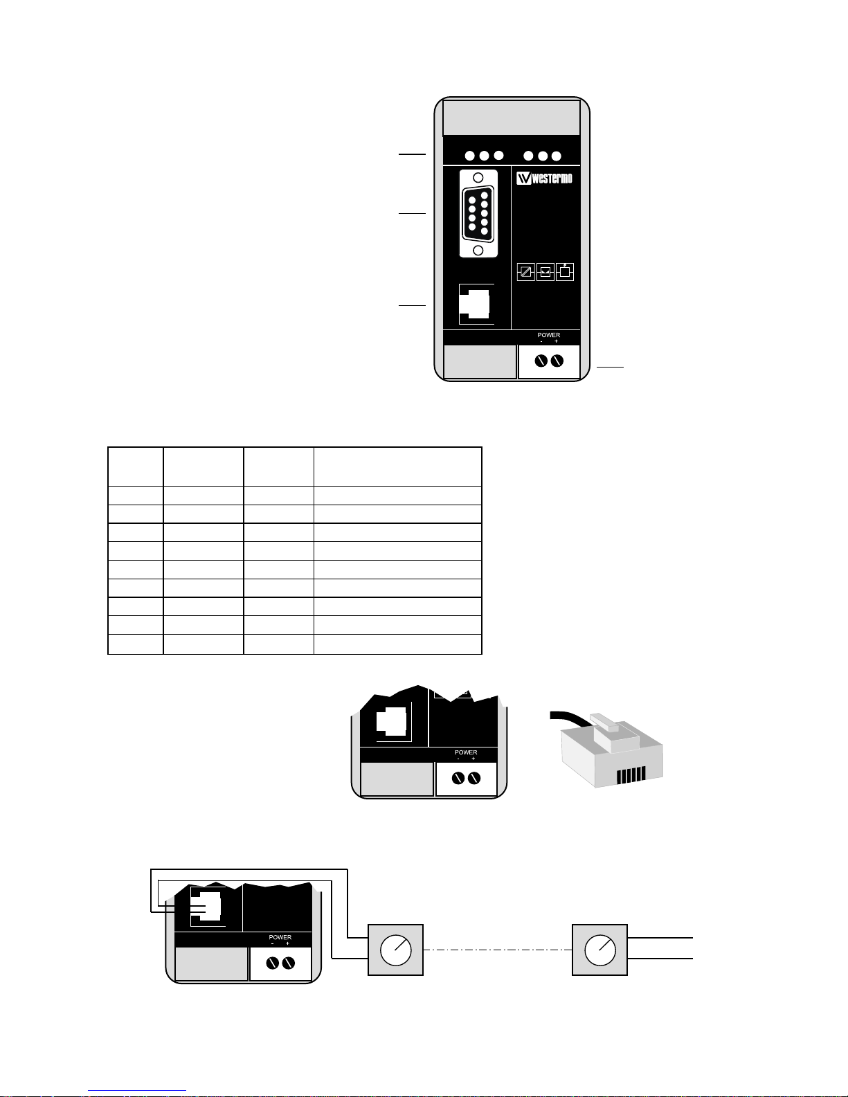
Installation
The modem should be connected in the following way:
Power connection is made
through screw-block at bottom
right corner. It is a 2-pole connector for 12–36 V DC supply.
Computers or other equipment
are connected through an 9-pole
D-sub RS-232/V.24 connection.
Do not use ribbon cable for
RS-232 connections.
LED’s
Power supply
Screw-block
9-pos
D-sub
RJ-11
Line
connection
TD-33
TEL.LINE
V24/RS-232-C
TD RD RTS DTR DCD PWR
TEL.LINE
TEL.LINE
▼ ▼ ▼
▼
9-pos. Direction Name Description
D-sub DCE-DTE
1 DCD Data carrier detect
2 RXD Receive data
3 TXD Transmit data
4 DTR Data terminal ready
5 - - - SG Signal ground
6 DSR Data Set Ready
7 RTS Request to send
8 CTS Clear to send
9 RI Ring indicator
RS-232/V.24 Connections
Pin outs for the 9-pole D-sub:
←
←
←
←
←
←
←
←
Line connection
The telephone line is connected
to the 2-pole RJ-11 connector.
2-wire lines are connected to the
two middle pins (3 & 4) in the
RJ-11 plug.
Typical TD-33 line connections
123456
RJ-11
plug
Telephone
Exchange
Telephone
Exchange
Dial up line 2-wire
3
4
76179-2201
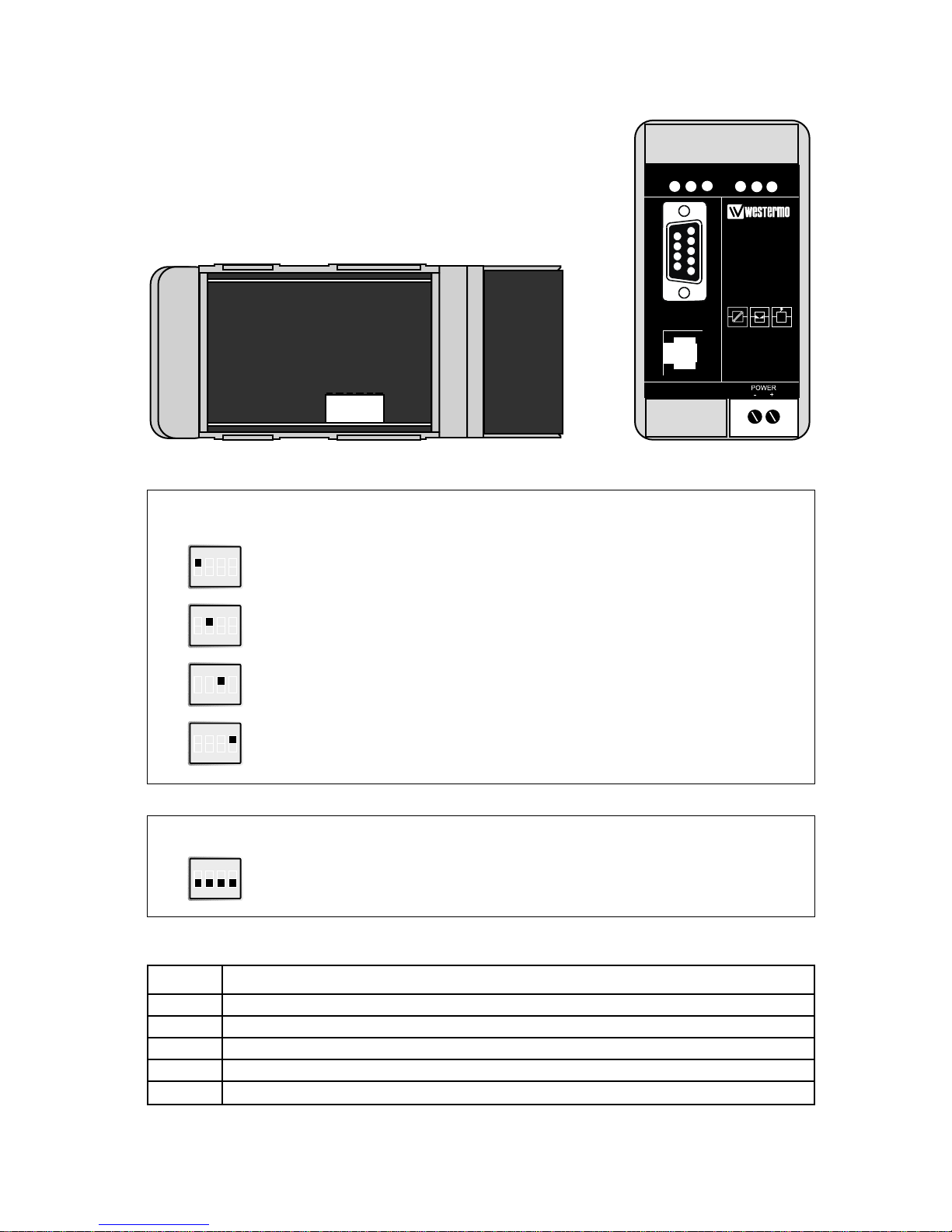
Switch 1
Factory Settings
DIP Switch Setup for Dial-up
Disconnect power before changing DIP-switches.
Use ESD-protection when changing switches.
The DIP-switches can be used to provide the following settings.
The DIP-Switches are underneath the top lid of the modem.
Non defined switches will be in off position.
ON
1234
ON
1234
TD-33
TEL.LINE
V24/RS-232-C
TD RD RTS DTR DCD PWR
S1:1-4
Software Watchdog Enable
ATQ1E0&C1&K0
PLC Mode (9 600 bit/s)
ON
1234
ON
1234
ATDS=0
DTR Hotcall Enable (9 600 bit/s)
ON
1234
Ignore DTE Characters
Related
AT-commands
LED Status Indicators
PWR Power Indication. Flashes if an error is detected
DTR Data Terminal Ready modem signal
RTS Request To Send modem signal
TD Transmitted Data: Displays data received from the local RS-232/V.24 port
RD Received Data: Displays data leaving the modem on the RS-232/V.24 port
DCD Data Carrier Detect modem signal

8 6179-2201
AT Commands
A – Answer
The modem will go off-hook and attempt to answer an incoming call if correct conditions
are met. Upon successful completion of answer handshake, the modem will go on-line in
answer mode.
The modem will enter the connect state after exchanging carrier with the remote modem.
If no carrier is detected within a period specified in register S7, the modem hangs up.
Any character entered during the connect sequence will abort the connection attempt.
Bn – ITU-T or Bell
When the modem is configured to allow either option, the modem will select Bell or
CCITT modulation for a line speed connection of 300 or 1200 bps according to the
parameter supplied. Any other line speed will use a CCITT modulation standard. The
parameter value, if valid, is written to S27 bit 6.
B0 Selects CCITT operation at 300 or 1200 bps during Call Establishment and a
subsequent connection. (Default)
B1 Selects BELL operation at 300 or 1200 bps during Call Establishment and a
subsequent connection.
\Bn – Transmit Break to Remote
In non-error correction mode, the modem will transmit a break signal to the remote
modem with a length in multiples of 100 ms according to parameter specified.
If a number in excess of 9 is entered, 9 is used. The command works in conjunction
with the \K command. In error correction mode, the modem will signal a break through
the active error correction protocol, giving no indication of the length.
\B1-\B9 Break length in 100 ms units. (Default = 3.) (Non-error corrected mode only.)
&Cn – RLSD (DCD) Option
The modem controls the RLSD output in accordance with the parameter supplied.
The parameter value, if valid, is written to S21 bit 5.
&C0 RLSD remains ON at all times.
&C1 RLSD follows the state of the carrier. (Default)
%C – Enable/Disable Data Compression
Enables or disables data compression negotiation. The modem can only perform data
compression on an error corrected link.
The parameter value, if valid, is written to S41 bits 0 and 1.
%C0 Disables data compression. Resets S46 bit 1.
%C1 Enables MNP 5 data compression negotiation. Resets S46 bit 1.
%C2 Enables V.42 bis data compression. Sets S46 bit 1.
%C3 Enables both V.42 bis and MNP 5 data compression. Sets S46 bit 1. (Default)

96179-2201
Dn – Dial
This command directs the modem to go on-line, dial according to the string entered and
attempt to establish a connection. If no dial string is supplied, the modem will go on-line
and attempt the handshake in originate mode.
NOTE:
If the ATD command is issued before the S1 register has cleared, the modem will respond
with the NO CARRIER result code.
The modem will behave as a data modem and will attempt to connect to another data
modem. The modem will have up to the period of time specified by register S6 to wait for
carrier and complete the handshake. If this time expires before the modem can complete
the handshake, the modem will go on-hook with the NO CARRIER response.This command will be aborted in progress upon receipt of any DTE character before completion of
the handshake.
Dial Modifiers
The valid dial string parameters are described below. Punctuation characters may be used
for clarity, with parentheses, hyphen, and spaces being ignored.
The valid dial string parameters are described below. Punctuation characters may be used
for clarity, with parentheses, hyphen, and spaces being ignored.
0-9 DTMF digits 0 to 9.
* The ’star’ digit (tone dialing only).
# The ’gate’ digit (tone dialing only).
A-D DTMF digits A, B, C, and D. Some countries may prohibit sending of these
digits during dialing.
L Re-dial last number: the modem will re-dial the last valid telephone number.
The L must be immediately after the D with all the following characters
ignored).
R This command will be accepted, but not acted on.
S=n Dial the number stored in the directory (n = 0 to 3). (See &Z.)
! Flash: the modem will go on-hook for a time defined by the value of S29.
W Wait for dial tone: the modem will wait for dial tone before dialing the digits
following ”W“. If dial tone is not detected within the time specified by S6
(EU), the modem will abort the rest of the sequence, return on-hook, and gener-
ate an error message.
@ Wait for silence: the modem will wait for at least 5 seconds of silence in the
call progress frequency band before continuing with the next dial string param-
eter. If the modem does not detect these 5 seconds of silence before the expira-
tion of the call abort timer (S7), the modem will terminate the call attempt with
a NO ANSWER message. If busy detection is enabled, the modem may termi-
nate the call with the BUSY result code. If answer tone arrives during execu-
tion of this parameter, the modem handshakes.
& Wait for credit card dialing tone before continuing with the dial string. If the
tone is not detected within the time specified by S6 (EU models), the modem
will abort the rest of the sequence, return on-hook, and generate an error mes-
sage.

10 6179-2201
, Dial pause: the modem will pause for a time specified by S8 before dialing the
digits following ”,”.
; Return to command state. Added to the end of a dial string, this causes the
modem to return to the command state after it processes the portion of the dial
string preceding the ”;”. This allows the user to issue additional AT commands
while remaining off-hook. The additional AT commands may be placed in the
original command line following the ”;” and/or may be entered on subsequent
command lines. The modem will enter call progress only after an additional
dial command is issued without the ”;” terminator. Use ”H” to abort the dial in
progress, and go back on-hook.
^ Toggles calling tone enable/disable: applicable to current dial attempt only.
( ) Ignored: may be used to format the dial string.
- Ignored: may be used to format the dial string.
<space> Ignored: may be used to format the dial string.
<i> Invalid character: will be ignored.
&Dn – DTR Option
This command interprets the ON to OFF transition of the DTR signal from the DTE in
accordance with the parameter supplied. The parameter value, if valid, is written to S21
bits 3 and 4. Also, see S25.
&D0, DTR drop is interpreted according to the current &Qn setting as follows: &Q0,
&Q5, &Q6 DTR is ignored (assumed ON). Allows operation with DTEs which
do not provide DTR. &Q1 DTR drop causes the modem to hang up. Auto-answer
is not affected. &Q2, &Q3 DTR drop causes the modem to hang up. Auto-answer
is inhibited.
&D1 DTR drop is interpreted according to the current &Qn setting as follows:
&Q0, &Q1, &Q5, &Q6 DTR drop is interpreted by the modem as if the asynchronous escape sequence had been entered. The modem returns to asynchronous
command state without disconnecting. &Q2, &Q3 DTR drop causes the modem
to hang up. Auto-answer is inhibited.
&D2 DTR drop is interpreted according to the current &Qn setting as follows:
&Q0 through &Q6 DTR drop causes the modem to hang up. Auto-answer is
inhibited. (Default)
&D3 DTR drop is interpreted according to the current &Qn setting as follows:
&Q0, &Q1, &Q5, &Q6 DTR drop causes the modem to perform a soft reset as if
the Z command were received. The &Y setting determines which profile is
loaded. &Q2, &Q3 DTR drop causes the modem to hang up. Auto-answer is
inhibited.
En – Command Echo
The modem enables or disables the echo of characters to the DTE according to the parameter supplied. The parameter value, if valid, is written to S14 bit 1.
E0 Disables command echo.
E1 Enables command echo. (Default)

116179-2201
%En – Enable/Disable Line Quality Monitor and AutoRetrain or Fallback/Fall Forward
Controls whether or not the modem will automatically monitor the line quality and request
a retrain (%E1) or fall back when line quality is insufficient or fall forward when line quality is sufficient (%E2). The parameter value, if valid, is written to S41 bits 2 and 6.
If enabled, the modem attempts to retrain for a maximum of 30 seconds.
%E0 Disable line quality monitor and auto-retrain.
%E1 Enable line quality monitor and auto-retrain.
%E2 Enable line quality monitor and fallback/fall forward. (Default)
Fallback/Fall Forward. When %E2 is active, the modem monitors the line quality (EQM).
When line quality is insufficient, the modem will initiate a rate renegotiation to a lower
speed within the V.34/V.32 bis/V.32 (TD-33) modulation speeds. The modem will keep
falling back within the current modulation if necessary until the speed reaches 2 400 bit/s
(V.34) or 4 800 bit/s (V.32). Below this rate, the modem will only do retrains if EQM
thresholds are exceeded. If the EQM is sufficient for at least one minute, the modem will
initiate a rate renegotiation to a higher speed within the current modulation speeds. The
rate renegotiations will be done without a retrain if a V.32 bis connection is established.
Speeds attempted during fallback/fall forward are those shown to be available in the rate
sequences exchanged during the initial connection. Fallback/fall forward is available in
error correction and normal modes, but not in direct mode.
&Fn – Restore Factory Configuration (Profile)
The modem loads the factory default configuration (profile). The factory defaults are
identified for each command and in the S-Register descriptions. A configuration (profile)
consists of a subset of S-Registers.
&F0 Restore factory configuration 0.
&F1 Restore factory configuration 1.
&Gn – Select Guard Tone
The modem generates the guard tone selected by this command according to the parameter supplied (DPSK modulation modes only). The parameter value, if valid, is written to
S23 bits 6 and 7.
&G0 Disables guard tone. (Default).
&G1 Disables guard tone.
&G2 Selects 1 800 Hz guard tone.
This command may not be permitted in some countries.
 Loading...