

Page 1
Tele modem
V.34
Telefonmodem
V.34
Modem Telephonique
V.34
6178-2010
www.westermo.se
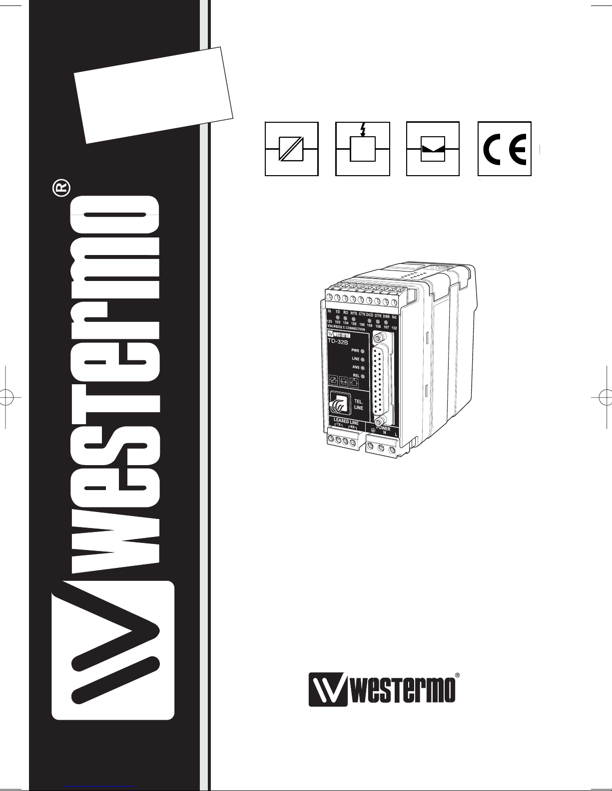
TD-32 B
Quickguide
Galvanic
Isolation
Transient
Protection
Balanced
Transmission
CE
Approved
REV.C • 6178-2010 2005.08 Mälartryck AB, Eskilstuna, Sweden
©
Westermo Teleindustri AB • 2005
Page 2

36178-2010
Introduction
The Westermo TD-32 B is an industrialised dial and leased line modem.This modem has been
developed to be used in industrial applications and has some features you would not expect to find
on a normal modem.Terminal data rates of up to 57.6 kbit/sec can be handled using data compresssion and error correction.The maximum line modulation speed is 14 400 bit/sec (V.32bis). Leased
line connections can be made on 2 or 4 wires.The modem can also be used on ordinary twisted
pair cables to provide long distance asynchronous communications.A watchdog facility continually
monitors the power supply and internal hardware as well as the operational software. In the event
of a problem the modem automatically resets.This feature has been included to make the unit more
suitable for use in unmanned locations.The TD-32 B is available in two standard versions for power
supply by 230 V AC or 12–36 V DC. Special 115 V AC and 36–60 V DC models are also available on
request.Westermo have implemented commands often left out of standard modems.Two examples
of these Westermo specific AT-commands are &D and &A (see AT-command description for further
information).The TD-32 B can handle 11 data bits and has a special 2 stop bit mode to allow the
unit to be used in applications many modems can’t handle.The TD-32 B has been designed with the
engineer in mind, hence the extensive information on the command set, S registers, DIP switched
and error codes.We have endeavoured to include all necessary information however if you need
more please do not hesitate to call us.
Safety
This equipment should only be installed by professional service personnel. If the unit is intended
for permanent connection to mains supply, there should be a readily accessible disconnect device
(circuit breaker) incorporated into the fixed wiring. Line connections on this equipment are designed
for connection to TNV circuits.The mains connection is classified as excessive voltage. Description
of the above classifications are given in EN60950:1992.
The TD-32 B DC shall only be installed to a power supply of the type SELV.
Installation
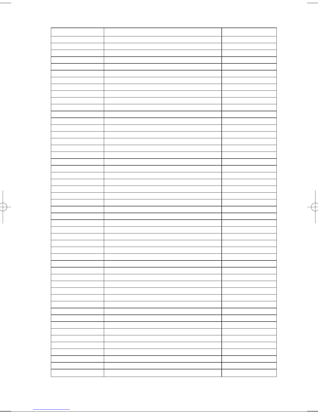
The modem should be connected in the following way:
Power connection is made through screwblock at bottom right corner ➅. For 115 V AC or 230 V AC
it is a 3-pole connector, and for 12–36 or 36–60 V DC a 2-pole connector. Computers or other
equipment are connected through an RS-232/V.24 connection.This connection can be made either
to the 25-pole D-sub ➄ or the 9-pole screw connector ➃. Do not use ribbon cable for RS-232
connections.The LED:s ➀ show the status of the serial DTE-side and general modem status.
Line connection
The telephone line is connected to the 6-pole RJ-12 connector ➁ or to the 4-pole screw block ➂ in
the bottom left side.When using the screw-block a strap plug supplied must be placed in the RJ-12
connector ➁. If this is not done the outgoing signal will not be connected to the screw-block ➂.
2-wire lines are connected to the two middle pins (3 & 4) in the RJ-12 plug ➁ or the TX screws ➂
(1 & 2).
4-wire lines are connected to the screw terminal ➂, transmitter to TX (1 & 2) and receiver to RX
(3 & 4).The pin numbers of the line connectors are described in picture.
DIP-switches
Disconnect power before changing DIP-switches!
Use ESD-protection when changing switches.The DIP-Switches are underneath the top lid of the
modem. Please refer to picture for placement of DIP-switches. Non defined switches will be in off
position. X-marked switches is “don’t care” for the described function.
Handshaking
The TD-32 B is delivered with a factory setting for “hardware handshake” with RTS-CTS which
means that if only TX, RX and GND are connected no data will be sent on the receiving modem’s
RS-232 connection unless RTS is high.The problem can be solved by placing a jumper between RTS
(screw terminal no 6) and for example DSR (screw terminal no 2) or by disabling the handshake
with the command AT&K0, or with switch 3:2 (switch settings).
A
B
C
Page 3
4 6178-2010
DIP-Switches
1234 567 8
0 = off 1 = on x = dont care
SW 1 Description Related
AT-commands
0 0 x x Standard dial-up
0 1 x x Leased Line,Answering ATE0Q1&C1&A1
1 1 x x Leased Line, Originating ATE0Q1&C1&A1
x x 1 x Do not abort if unwanted characters
are received during connection AT&A1
x x x 1 Escape sequence disabled
(all commands ignored in on-line mode) ATE0Q1&C1
SW 2
0 x x x x x x x 2-8 are not used
1 x x x x x x x For use of SW2:2 to 7
1 0 0 x x x x x Asynchronous communication
1 1 0 x x x x x Synchronous, external clock. Clock from D-Sub pin 24
1 0 1 x x x x x Synchronous, internal clock.
The modem generates the clock
1 1 1 x x x x x Synchronous slave. Clock from line
1 x x 1 x x x x DTR/DSR disconnected AT&S0&D0&C0
SW 3
0 x x x x x x x 4-wire line connection
1 x x x x x x x 2-wire line connection
x 1 x x x x x x Flow control off AT&K0
x x 1 x x x x x REL-mode disbled AT\N0
x x x 1 x x x x Speaker off ATM0
x x x x x 1 x x PLC settings ATQ1E0&C1&K0&A1
x x x x x x 1 x DCD follows the state of the line carrier AT&C1
x x x x x x x 1 Line monitor disabled and no re-training AT%E0
SW 4
0 0 0 0 x x x x Automatic detection of serial speed and format
1 0 0 0 x x x x 300 bit/s
0 1 0 0 x x x x 600 bit/s
1 1 0 0 x x x x 1 200 bit/s
0 0 1 0 x x x x 2 400 bit/s
1 0 1 0 x x x x 4 800 bit/s
0 1 1 0 x x x x 9 600 bit/s
1 1 1 0 x x x x 19 200 bit/s
0 0 0 1 x x x x 38 400 bit/s
1 0 0 1 x x x x 57 600 bit/s
x x x x 0 0 0 x 7 bits no parity [7N]
x x x x 1 0 0 x 7 bits even parity [7E]
x x x x 0 1 0 x 7 bits odd parity [7O]
x x x x 1 1 0 x 8 bits no parity [8N]
x x x x 0 0 1 x 8 bits even parity [8E]
x x x x 1 0 1 x 8 bits odd parity [8O]
x x x x 0 1 1 x Direct mode [8E] or [8O] in command mode AT\N1
x x x x 1 1 1 x Direct mode [7E] or [7O], [8N] in command mode AT\N1
x x x x x x x 1 2 stop bits
SW 5
0 0 0 0 x x x x Use saved parameters
1 0 0 0 x x x x V.21, 300 bit/s ATF1
0 0 1 0 x x x x V.22, 1 200 bit/s ATF4
1 0 1 0 x x x x V.22 bis 2 400 bit/s ATF5
0 1 1 0 x x x x V.32 bis 4 800 bit/s ATF6
1 1 1 0 x x x x V.32 bis 7 200 bit/s ATF7
0 0 0 1 x x x x V.32 bis 9 600 bit/s ATF8
1 0 0 1 x x x x V.32 bis 12 000 bit/s ATF9
0 1 0 1 x x x x V.32 bis 14 400 bit/s ATF10
1 1 0 1 x x x x V.34 19 200 bit/s ATF11
0 0 1 1 x x x x V.34 24 400 bit/s ATF12
1 0 1 1 x x x x V.34 28 800 bit/s ATF13
0 1 1 1 x x x x V.34 33 600 bit/s ATF14
1 1 1 1 0 x x x Auto detect mode V.32 bis ATF0
1 1 1 1 1 x x x Auto detect mode V.34
Page 4
56178-2010
Short summary of AT-commands
Command Description Range (n)
A/ Re-execute command –
A Answer –
\An Select maximum MNP block size 0–3
&An Interrupt connection negotiation 0–1
Bn Selecting ITU-T or Bell 0–1
&Bn DTR dial option 0–1
\Bn Transmit Break to remote 0–5
*B Display blacklisted phone numbers –
Cn Carrier control –
&Cn DCD option 0–1
%Cn Enable/Disable data compression 0–3
Dn Dialling command –
&Dn DTR option 0–3
*D Display delayed numbers –
En Command echo 0–1
%En Line quality and retest check 0–2
Fn Select modulation 0–2, 4–10
&F Restore factory configuration –
&Gn Guard tone 0–2
Hn Disconnection 0–1
*Hn MNP10 connection speed 0–2
In Identification report 0–9
&Kn Flow control 0, 3–5
\Kn Break control 0–5
–Kn MNP extended services 0–2
Ln Speaker volume 0–3
%L Signal level on line –
Mn Speaker control 0–3
&Mn Asynchronous/synchronous 0–3
)Mn “Cellular” MNP10 power level adjustment 0–2
+MS Modulation selection –
\Nn Operating mode 0–5
On Return to communication mode 0–5
Qn Result code control 0–1
&Qn Asynchronous/synchronous mode 0–6
%Q Line signal quality –
&Rn RTS/CTS options 0–1
Sn Read or write s-registers –
&Sn DSR control 0–1
&Tn Test and diagnostics 0–1
Vn Result code form 0–1
&Vn Display configuration 0–1
\Vn Result codes displayed in one row 0–1
Wn Connect message control 0–2
&Wn Save current configuration 0–1
Xn Extended result codes 0–4
&Xn Select synchronous clock source 0–2
&Yn Selection of default profile 0–1
Zn Soft reset and restore profile 0–1
&Zn Store telephone numbers 0–3
Page 5
6 6178-2010
Termination
2-wire
TD-32 B/485 (RS-422/485 interface)
As an option the TD-32 B can be supplied with an RS-422/485 interface. This product is referred to as the TD-32 B/485.
On the TD-32 B/485 the RS-232/V.24 connection on the screw terminal on upper front side of the unit has been replaced with an RS422/485 interface. All other features remain identical
between the standard TD-32 B and TD-32 B/485.
The TD-32 B/485 can still be connected to an RS-232/V.24 port using
the 25-pole D-sub. Please note that there is no galvanic isolation
between the RS-232 and the RS-422/485 ports so they should not be
connected simultaneously.
The RS-422/485 connections are made as shown below.
Please note that the selection of 2 or 4 wire and termination or no termination is done by linking between some of the screw terminals.
The default switch settings on a TD-32 B/485 is: SW3:1 and SW3:6
set to ON, the rest is OFF.
R+
RS 422/485
R-T+T-GND
PWR
TD
RD
RTS
DCD
LINE
ANS
REL
T4T2
V24/RS232-C
WIRE
2/4S1
1234567
8
9
B
TD-32 B/485
R+
RS 422/485
R-T+T-GND
PWR
TD
RD
RTS
DCD
LINE
T4T2
V24/RS232-C
WIRE
2/4S1
1234567
8
9
B
R+
RS 422/485
R-T+T-GND
PWR
TD
RD
RTS
DCD
LINE
T4T2
V24/RS232-C
WIRE
2/4S1
1234567
8
9
B
Termination
4-wire
4-wire
R+
RS 422/485
R-T+T-GND
PWR
TD
RD
RTS
DCD
LINE
T4T2
V24/RS232-C
WIRE
2/4S1
1234567
8
9
B
Connection
RS-485
R+
RS 422/485
R-T+T-GND
PWR
TD
RD
RTS
DCD
LINE
T4T2
V24/RS232-C
WIRE
2/4S1
1234567
8
9
B
Connection
RS-422
Page 6

76178-2010
Einleitung
Das Westermo TD-32 B ist ein industrielles Wahl- und Standleitungsmodem. Es wurde speziell für
industrielle Anwendungen entwickelt und besitzt einige Leistungsmerkmale die man bei einem normalen Modem vergeblich sucht.Terminal Übertragungsgeschwindigkeiten von bis zu 57.6 kbit/s können durch Datenkompression erreicht werden. Im Fernmeldenetz beträgt die maximale Übertragungsgeschwindigkeit 14 400 bit/s (V.32bis). Es kann auf 2-/4-Draht Standleitungen eingesetzt werden.
Das TD-32 B kann aber auch mit gewöhnlichen Twisted-Pair Leitungen für lange asynchrone
Datenverbindungen benutzt werden. Ein integrierter „Watchdog“ achtet auf die
Spannungsversorgung, die interne Hardware und die Software. Falls ein Problem auftreten sollte fährt
das Modem einen automatischen Reset. Diese Funktion wurde integriert damit das TD-32 B besser
für den unbemannten Betrieb geeignet ist. Das TD-32 B ist in zwei Standardversionen, bezogen auf
die Spannungsversorgung, erhältlich: 230 V AC und 12–36 V DC. Spezialversionen für 115 V AC und
36–60 V DC sind auf Anfrage erhältlich. Zwei Beispiele für spezielle Befehle die Westermo implementiert hat sind, die AT Befehle &D und &A (Siehe AT-Befehlssatz Beschreibung). Das TD-32 B arbeitet
auch mit 11 Datenbits und hat einen speziellen 2 Stopbit Modus für Applikationen bei denen andere
Modems versagen. Das TD-32 wurde entwickelt, mit Blick auf den, der es einsetzt.Aus diesem
Grunde haben wir versucht, alle notwendigen Informationen über den Befehlssatz, die S-Register,
DIP-Schalter und Fehlercodes in dieser Bedienungsanleitung unterzubringen. Sollten Sie weitere
Informationen benötigen, zögern Sie nicht uns anzurufen.
Sicherheitshinweise
Das Gerät sollte nur von geschulten Personen angeschlossen und in Betrieb genommen werden.
Wenn es dauernd an Spannung angeschlossen ist, sollte darauf geachtet werden, daß eine geeignete
Absicherung vorhanden ist. Alle Anschlüsse am Gerät wurden für TNV Stromkreise entwickelt.
Die 230 V Verbindung ist als Hochspannungsanschluß klassifiziert Nähere Informationen darüber
erhalten Sie unter EN60950:1992.
Das TD-32 sollte nur an SELV Spannungsversorgungen angeschlossen werden.
Installation
Das Modem wird wie folgt angeschlossen:
Die Spannungsversorgung wird über die Anschlußklemmen rechts unten am Modem angeschlossen
➅. Bei 115 V AC oder 230 V AC Geräten ist es ein 3-poliger Stecker, bei DC-Geräten ein 2-poliger.
Ein Computer oder ein anderes Gerät wird über RS-232-Anschluß, entweder mit der 9-poligen
Klemmenleiste ➃ an der Oberkante des Modems oder über dei 25-polige Sub-D-Buchse vorne am
Modem angeschlossen ➄. Bei Anschluß an die Sub-D-Buchse darf kein Flachbandkabel benutzt werden. Die LED’s ➀ zeigen den Status der seriellen Schnittstelle und die wichtigsten Modemdaten.
Leitungsanschluss
Die Fernmeldeleitung ist an die 6-polige RJ-12-Buchse ➁ auf der Gerätefront oder die 4-polige
Klemmenleiste ➂ unten links anzuschließen.Wenn der Anschluß über die Klemmenleiste erfolgen
soll, muß ein Brückenstecker in der RJ-12-Buchse gesteckt sein.Wird dies nicht beachtet, sind die
Schraubklemmen ➂ nicht mit der Telefonleitung verbunden. Zweidrahtleitungen werden an Pin 3
und 4 des RJ-12-Anschlusses ➁ oder mit den TX-Klemmen 1 & 2 an der Klemmenleiste ➂ ganz
links verbunden.Vierdrahtleitungen werden an der Klemmenleiste ➂ angeschlossen, und zwar
Sendeleitungen an TX (1 & 2), Empfangsleitungen an RX (3 & 4). Siehe Bild weiter unten.
DIP-Schalter
Vor dem Einstellen der DIP-Schalter die Versorgungsspannung abschalten.
Schutzmaßnahmen gegen elektrostatische Aufladung beachten.
Die DIP-Schalter befinden sich unter der Abdeckung oben am Modem
(1 = Ein, 0 = Aus, x = beliebige Stellung).
Nicht angegebene Schalter müssen in der Stellung 0 (Aus) sein.
Handshake
Das TD-32B ist werkseitig auf Hardware-Handshake mit RTS-CTS eingestellt. Das bedeutet, daß bei
alleinigem Anschluß von TX, RX und GND nur dann Daten von der RS-232-Schnittstelle des
Gegenmodems gesendet werden, wenn das RTS-Signal hoch ist. Dieses Problem kann dadurch behoben werden, daß man eine Brücke zwischen RTS (Klemme 6) und z.B. DSR (Klemme 2) anbringt
oder den Handshake mit dem Befehl AT&K0 deaktiviert oder DIP-Schalter SW3:2 setzt.
A
B
C
Page 7

8 6178-2010
DIP-Schalter
1234 567 8
0 = off 1 = on x = nicht benutzt
SW 1 Beschreibung Related
AT-commands
0 0 x x Standard Wählleitungen
0 1 x x Standleitungen,Antwortfunktion ATE0Q1&C1&A1
1 1 x x Standleitungen,Wählfunktion ATE0Q1&C1&A1
x x 1 x Keine Unterbrechung des Verbindungsaufbaus
bei eintreffenden Zeichen AT&A1
x x x 1 Escape Sequenz abgeschaltet (Befehle werden
während einer Verbindung ignoriert) ATE0Q1&C1
SW 2
0 x x x x x x x Schalter 2–8 nicht benutzt
1 x x x x x x x Schalter 2–8 werden angewendet
1 0 0 x x x x x Asynchrone Verbindungen
1 1 0 x x x x x Synchron, externer Takt Über Pin 24 des Sub-D
1 0 1 x x x x x Synchron, interner Takt. Das Modem
generiert den Takt
1 1 1 x x x x x Synchroner Slave.Takt von Leitung
1 x x 1 x x x x DTR/DSR abgeschaltet AT&S0&D0&C0
SW 3
0 x x x x x x x 4-Draht Verbindungen
1 x x x x x x x 2-Draht Verbindungen
x 1 x x x x x x Handshake aus AT&K0
x x 1 x x x x x REL-Modus abgeschaltet AT\N0
x x x 1 x x x x Lautsprecher immer aus ATM0
x x x x x 1 x x SPS-Einstellungen ATQ1E0&C1&K0&A1
x x x x x x 1 x DCD folgt dem Träger auf der Leitung AT&C1
x x x x x x x 1 Leitungsüberwachung und Rückschalten aus AT%E0
SW 4
0 0 0 0 x x x x Automatische Geschwindigkeits- und Formateinstellung
1 0 0 0 x x x x 300 bit/s
0 1 0 0 x x x x 600 bit/s
1 1 0 0 x x x x 1 200 bit/s
0 0 1 0 x x x x 2 400 bit/s
1 0 1 0 x x x x 4 800 bit/s
0 1 1 0 x x x x 9 600 bit/s
1 1 1 0 x x x x 19 200 bit/s
0 0 0 1 x x x x 38 400 bit/s
1 0 0 1 x x x x 57 600 bit/s
x x x x 0 0 0 x 7 bits no parity [7N]
x x x x 1 0 0 x 7 bits even parity [7E]
x x x x 0 1 0 x 7 bits odd parity [7O]
x x x x 1 1 0 x 8 bits no parity [8N]
x x x x 0 0 1 x 8 bits even parity [8E]
x x x x 1 0 1 x 8 bits odd parity [8O]
x x x x 0 1 1 x Direktmodus. [8E] or [8O] im Befehlsmodus AT\N1
x x x x 1 1 1 x Direktmodus. [7E] or [7O], [8N] im Befehlsmodus AT\N1
x x x x x x x 1 2 stop bits
SW 5
0 0 0 0 x x x x Use saved parameters
1 0 0 0 x x x x V.21, 300 bit/s ATF1
0 0 1 0 x x x x V.22, 1 200 bit/s ATF4
1 0 1 0 x x x x V.22 bis 2 400 bit/s ATF5
0 1 1 0 x x x x V.32 bis 4 800 bit/s ATF6
1 1 1 0 x x x x V.32 bis 7 200 bit/s ATF7
0 0 0 1 x x x x V.32 bis 9 600 bit/s ATF8
1 0 0 1 x x x x V.32 bis 12 000 bit/s ATF9
0 1 0 1 x x x x V.32 bis 14 400 bit/s ATF10
1 1 0 1 x x x x V.34 19 200 bit/s ATF11
0 0 1 1 x x x x V.34 24 400 bit/s ATF12
1 0 1 1 x x x x V.34 28 800 bit/s ATF13
0 1 1 1 x x x x V.34 33 600 bit/s ATF14
1 1 1 1 0 x x x Auto detect mode V.32 bis ATF0
1 1 1 1 1 x x x Auto detect mode V.34
Page 8

96178-2010
Kurzübersicht der AT-Befehle
Befehl Beschreibung Bereich
A/ Re-execute command –
A Answer –
\An Select maximum MNP block size 0–3
&An Interrupt connection negotiation 0–1
Bn Selecting ITU-T or Bell 0–1
&Bn DTR dial option 0–1
\Bn Transmit Break to remote 0–5
*B Display blacklisted phone numbers –
Cn Carrier control –
&Cn DCD option 0–1
%Cn Enable/Disable data compression 0–3
Dn Dialling command –
&Dn DTR option 0–3
*D Display delayed numbers –
En Command echo 0–1
%En Line quality and retest check 0–2
Fn Select modulation 0–2, 4–10
&F Restore factory configuration –
&Gn Guard tone 0–2
Hn Disconnection 0–1
*Hn MNP10 connection speed 0–2
In Identification report 0–9
&Kn Flow control 0, 3–5
\Kn Break control 0–5
–Kn MNP extended services 0–2
Ln Speaker volume 0–3
%L Signal level on line –
Mn Speaker control 0–3
&Mn Asynchronous/synchronous 0–3
)Mn “Cellular” MNP10 power level adjustment 0–2
+MS Modulation selection –
\Nn Operating mode 0–5
On Return to communication mode 0–5
Qn Result code control 0–1
&Qn Asynchronous/synchronous mode 0–6
%Q Line signal quality –
&Rn RTS/CTS options 0–1
Sn Read or write s-registers –
&Sn DSR control 0–1
&Tn Test and diagnostics 0–1
Vn Result code form 0–1
&Vn Display configuration 0–1
\Vn Result codes displayed in one row 0–1
Wn Connect message control 0–2
&Wn Save current configuration 0–1
Xn Extended result codes 0–4
&Xn Select synchronous clock source 0–2
&Yn Selection of default profile 0–1
Zn Soft reset and restore profile 0–1
&Zn Store telephone numbers 0–3
Page 9

10 6178-2010
2-Draht
Termination
TD-32/485 (RS-422/485 Schnittstelle)
Das TD-32 B ist auch optional mit einer RS-422/485 Schnittstelle
erhältlich. Dieses Modem trägt den Namen TD-32B/485.
Beim TD-32 B/485 wurde der Anschluß einer RS-232 Schnittstelle über
Schraubklemme gegen eine RS-422/485 Schnittstelle ausgetauscht. Alle
anderen Leistungsmerkmale des TD-32 B und TD-32 B/485 sind identisch.
Das TD-32 B/485 kann über den 25-poligen Sub-D Anschluß auch an
eine RS-232 Schnittstelle angeschlossen werden. Es existiert keine galvanische Trennung zwischen der RS-232 und der RS-422/485
Schnittstelle, da diese nie gleichzeitig benutzt werden sollen. Der
Anschluß einer RS-422/485 Schnittstelle wird unten beschrieben. Bitte
beachten Sie, daß die 2/4-Draht Einstellung und Termination über
Jumper geschieht, die an der Schraubklemme Pin 5-9 angeschlossen
werden.
Die Werkseinstellung der DIP-Schalter des TD-32B/485 ist: SW3:1
und SW3:6 auf ON, der Rest OFF.
R+
RS 422/485
R-T+T-GND
PWR
TD
RD
RTS
DCD
LINE
ANS
REL
T4T2
V24/RS232-C
WIRE
2/4S1
1234567
8
9
B
TD-32 B/485
R+
RS 422/485
R-T+T-GND
PWR
TD
RD
RTS
DCD
LINE
T4T2
V24/RS232-C
WIRE
2/4S1
1234567
8
9
B
R+
RS 422/485
R-T+T-GND
PWR
TD
RD
RTS
DCD
LINE
T4T2
V24/RS232-C
WIRE
2/4S1
1234567
8
9
B
4-Draht
Termination
4-Draht
R+
RS 422/485
R-T+T-GND
PWR
TD
RD
RTS
DCD
LINE
T4T2
V24/RS232-C
WIRE
2/4S1
1234567
8
9
B
RS-485
Anschluß
R+
RS 422/485
R-T+T-GND
PWR
TD
RD
RTS
DCD
LINE
T4T2
V24/RS232-C
WIRE
2/4S1
1234567
8
9
B
RS-422
Anschluß
Page 10

116178-2010
Inledning
Westermo TD-32 B är ett telemodem för fasta och uppringda förbindelser. Modemet har utvecklats
för att användas i industriella tillämpningar och har en del funktioner som normalt inte finns på
andra modem.Terminalhastigheter upp till 57,6 kbit/s kan hanteras med komprimering och felkorrigering. Den maximala linjehastigheten är 14 400 bit/s (V.32bis). Fast uppkopplad förbindelse kan ske
på 2-/4-tråd. Modemet kan också användas på vanliga tvinnade trådpar för att få till asynkron kommunikation över längre sträckor. En övervakningskrets kontrollerar hela tiden matningsdelen och den
övriga hårdvaran samt att programmet i processorn inte stannar. Om ett fel inträffar eller att matningsspänningen blir för låg, kommer modemet att återställas. Denna funktion är speciellt nyttig för
tillämpningar på obemannade platser.TD-32 B finns tillgänglig i två standardversioner med matningssspänning på 230 V AC eller 12–36 V DC. Specialversioner för 115 V AC eller 36–55 V DC kan också
levereras.Westermo har implementerat en del specialkommandon som i vanliga fall inte förekommer
i standardmodem. Exempelvis kommandot &D som ger möjlighet att göra uppringning med hårdvarusignal eller kommandot &A som förhindrar nedkoppling av uppkopplingsförsök, om det kommer in
tecken på serieporten.TD-32 B kan hantera 11 bitars data och även 2 stopp bitar, vilket gör att
modemet kan användas i många tillämpningar som andra modem inte klarar.TD-32 B har konstruerats med installatören i åtanke.Alla kommandon och inställningar finns dokumenterade i installationsmanualen, men tveka inte att kontakta oss för att få hjälp om den bifogade informationen inte är tillräcklig.
Säkerhet
Denna utrustning skall endast installeras av installatörer eller personer med nödvändig kännedom
om elsäkerhet. Om enheten ansluts till en fast installation skall strömförsörjningen kunna brytas med
en lätt åtkomlig strömbrytare. Utrustningen är utförd enligt standarden EN60950:1992.
TD-32 B DC skall endast anslutas till en strömförsörjning av typen SELV.
Installation
Modemet skall anslutas på följande sätt:
Matningsspänningen ansluts genom skruvplinten i nedre högra hörnet ➅. För 115V AC eller
230 V AC används en 3-polig anslutning och för 12–36 eller 36–55 V DC används en 2-polig.
Datorer eller annan utrustning ansluts via en RS-232/V.24 anslutning. Denna anslutning kan göras
antingen genom den 25-poliga D-suben ➄ eller den 9-poliga skruvplinten ➃.Använd inte bandkabel
för RS-232/V.24 anslutningarna. LED:arna ➀ visar generell modem status samt information om det
seriella interfacet.
Linjeanslutning
Telefonlinjen ansluts till den 6-poliga RJ-12 kontakten ➁ eller den 4-poliga skruvplinten ➂ nere till
vänster. När man använder skruvplinten, måste den medlevererade byglingskontakten sättas i RJ-12
anslutningen ➁. Om detta inte utförs, kommer inte linjesignalen att kopplas till kruvplintsanslutningen
➂. 2-trådiga linjer (både fast och uppringande) ansluts till de två mittersta pinnarna (3 & 4) i
RJ-12 anslutningen ➁ eller till TX skruvarna ➂ (1 & 2). 4-trådiga linjer ansluts till skruvplinten ➂,
sändaren ligger på TX (1 & 2) och mottagaren på RX (3 & 4). De olika linjeanslutningarna är beskrivna i figur B
Switch/Omkopplarinställning för fast-och uppringd linje
OBS! Koppla ur spänningen före DIP-switch ändringar och använd ESD-skydd vid omställning av switchar!
DIP-Switcharna (omkopplarna) finns under locket på toppen av modemet. Placering av switcharna
framgår av figur [C]. Icke definierade switchar skall vara i läge OFF. Switchar som är markerade med
X vid en specifik inställning påverkar inte den aktuella inställningen.
Handskakning
TD-32 B är från början inställd för hårdvaruhandskakning med RTS-CTS vilket innebär att om
endast TX, RX och GND är anslutet, kommer inte data att sändas ut på det mottagande modemets
RS-232/V.24 anslutning om inte RTS signalen ligger aktiv. Problemet går att lösa med en byglingstråd
mellan RTS (skruv 6) och DSR (skruv 2) i skruvplinten eller genom att stänga av handskakningen
med mjukvarukommandot AT&K0, eller med switch 3:2 (se switchinställningar).
A
B
C
Page 11

12 6178-2010
DIP-Switchar
1234 567 8
0 = off 1 = on x = används ej
SW 1 Beskrivning AT kommandon
0 0 x x Uppringd förbindelse
0 1 x x Fast uppkoppling, svarande ATE0Q1&C1&A1
1 1 x x Fast uppkoppling, uppringande ATE0Q1&C1&A1
x x 1 x Stänger av nedkoppling av förbindelse vid
data in på serieport vid uppkopplingsförsök AT&A1
x x x 1 Escape sekvensen inaktiv
(alla kommandon ignoreras i on-line mod) ATE0Q1&C1
SW 2
0 x x x x x x x 2–8 används ej
1 x x x x x x x För att använda SW2:2 till 7
1 0 0 x x x x x Asynkron kommunikation
1 1 0 x x x x x Synkron Extern Klocka från pin 24 i D-sub
1 0 1 x x x x x Synkron Intern, Modemet skapar klockan
1 1 1 x x x x x Synkron återkopplad. Klockan från linjen
1 x x 1 x x x x DTR/DSR bortkopplad AT&S0&D0&C0
SW 3
0 x x x x x x x 4-tråds linjekoppling
1 x x x x x x x 2-tråds linjekoppling
x 1 x x x x x x Flödeskontroll avstängd AT&K0
x x 1 x x x x x REL-mod frånslagen AT\N0
x x x 1 x x x x Högtalare alltid OFF ATM0
x x x x x 1 x x PLC inställningar ATQ1E0&C1&K0&A1
x x x x x x 1 x DCD inställningar AT&C1
x x x x x x x 1 Ingen linjeövervakning eller automatisk
omförhandling av linjen AT%E0
SW 4
0 0 0 0 x x x x Automatisk hastighet och formatinställning
1 0 0 0 x x x x 300 bit/s
0 1 0 0 x x x x 600 bit/s
1 1 0 0 x x x x 1 200 bit/s
0 0 1 0 x x x x 2 400 bit/s
1 0 1 0 x x x x 4 800 bit/s
0 1 1 0 x x x x 9 600 bit/s
1 1 1 0 x x x x 19 200 bit/s
0 0 0 1 x x x x 38 400 bit/s
1 0 0 1 x x x x 57 600 bit/s
x x x x 0 0 0 x 7 bitar, ingen paritet, [7N]
x x x x 1 0 0 x 7 bitar jämn paritet, [7E]
x x x x 0 1 0 x 7 bitar udda paritet, [7O]
x x x x 1 1 0 x 8 bitar ingen paritet, [8N]
x x x x 0 0 1 x 8 bitar jämn paritet, [8E]
x x x x 1 0 1 x 8 bitar udda paritet, [8O]
x x x x 0 1 1 x Direktmod [8E] eller [8O] i kommando mod AT\N1
x x x x 1 1 1 x Direktmod [7E], [7O] eller [8N] i kommando mod AT\N1
x x x x x x x 1 2 stoppbitar
SW 5
0 0 0 0 x x x x Använd sparade parametrar
1 0 0 0 x x x x V.21, 300 bit/s ATF1
0 0 1 0 x x x x V.22, 1 200 bit/s ATF4
1 0 1 0 x x x x V.22 bis 2 400 bit/s ATF5
0 1 1 0 x x x x V.32 bis 4 800 bit/s ATF6
1 1 1 0 x x x x V.32 bis 7 200 bit/s ATF7
0 0 0 1 x x x x V.32 bis 9 600 bit/s ATF8
1 0 0 1 x x x x V.32 bis 12 000 bit/s ATF9
0 1 0 1 x x x x V.32 bis 14 400 bit/s ATF10
1 1 0 1 x x x x V.34 19 200 bit/s ATF11
0 0 1 1 x x x x V.34 24 400 bit/s ATF12
1 0 1 1 x x x x V.34 28 800 bit/s ATF13
0 1 1 1 x x x x V.34 33 600 bit/s ATF14
1 1 1 1 0 x x x Automatisk linjehastighet V.32 bis ATF0
1 1 1 1 1 x x x Automatisk linjehastighet V.34
Page 12

136178-2010
Kort beskrivning av AT-kommandon
Kommando Beskrivning Parametrar
A/ Repetera senaste kommando –
A Svarar –
\An Maximal storlek på MNP block 0–3
&An Ignorera tecken under uppkoppling 0–1
Bn Val av CCITT eller BELL 0–1
&Bn Uppringning med DTR 0–1
\Bn ”Break” signal till fjärrmodem 0–5
*B Svartlistade telefonnummer –
Cn Bärvågskontroll –
&Cn Hantering av DCD 0–1
%Cn Datakomprimering 0–3
Dn Uppringningskommando –
&Dn DTR kontroll 0–3
*D Visa fördröjda telefonnummer –
En Eko av kommando 0–1
%En Linjekvalitets och återförsökstest 0–2
Fn Val av linjemoduleringsprincip 0–2, 4–10
&F Återställning till fabriksparametrar –
&Gn ”Guard tone” Skyddston 0–2
Hn Nedkoppling 0–1
*Hn MNP10 uppkopplingshastighet 0–2
In Identifikation 0–9
&Kn Flödeskontroll 0, 3–5
\Kn ”Break” kontroll 0–5
–Kn MNP utökade funktioner 0–2
Ln Högtalarvolym 0–3
%L Signalnivå på linjen –
Mn Högtalarkontroll 0–3
&Mn Asynkron/Synkron mod 0–3
)Mn MNP10 effektnivåjustering 0–2
+MS Val av modulation –
\Nn Arbetssätt 0–5
On Återgå till kommunikationsläge 0–5
Qn Resultatkodskontroll 0–1
&Qn Asynkron/Synkron mod 0–6
%Q Linjesignalkvalitet –
&Rn RTS/CTS kontroll 0–1
Sn S-register kontroll –
&Sn DSR kontroll 0–1
&Tn Test och diagnostik 0–1
Vn Resultatkodsformat 0–1
&Vn Aktiv och sparad konfiguration 0–1
\Vn Resultatkoder på en rad 0–1
Wn Uppkopplingsmeddelanden 0–2
&Wn Spara nuvarande inställningar 0–1
Xn Utökade resultatkoder 0–4
&Xn Val av synkron klocka 0–2
&Yn Val av parameterblock 0–1
Zn Mjukvarureset / återgå till sparad konfiguration 0–1
&Zn Spara telefonnummer 0–3
Page 13

14 6178-2010
Terminering
2-wire
TD-32 B/485 (RS-422/485 gränssnitt)
Som en option kan TD-32 B förses med RS-422/485 gränssnitt. Denna
produkt heter TD-32 B/485. På TD- 2 B/485 är RS-232/V.24 anslutningen i den övre skruvplinten ersatt med RS-422/485. Alla andra funktioner är identiska med en standard TD-32 B. TD-32 B/485 kan fortfarande
anslutas till en RS-232/V.24 port genom att använda den 25-poliga
D-sub kontakten. Observera att det inte finns någon galvanisk isolation
mellan RS-232/V.24 och RS-422/485 anslutningarna vilket gör att dessa
inte skall anslutas samtidigt. RS-422/485 anslutningarna görs som visas
här nedan. Val av 2- eller 4-tråds linjer och terminering eller icke terminering görs med byglingar mellan några av skruvplintarna. Switchinställning vid leverans från fabrik på en TD-32 B/485 är: 3:1 och 3:6
ON, resten OFF.
R+
RS 422/485
R-T+T-GND
PWR
TD
RD
RTS
DCD
LINE
ANS
REL
T4T2
V24/RS232-C
WIRE
2/4S1
1234567
8
9
B
TD-32 B/485
R+
RS 422/485
R-T+T-GND
PWR
TD
RD
RTS
DCD
LINE
T4T2
V24/RS232-C
WIRE
2/4S1
1234567
8
9
B
R+
RS 422/485
R-T+T-GND
PWR
TD
RD
RTS
DCD
LINE
T4T2
V24/RS232-C
WIRE
2/4S1
1234567
8
9
B
Terminering
4-tråd
4-tråd
R+
RS 422/485
R-T+T-GND
PWR
TD
RD
RTS
DCD
LINE
T4T2
V24/RS232-C
WIRE
2/4S1
1234567
8
9
B
Anslutning
RS-485
R+
RS 422/485
R-T+T-GND
PWR
TD
RD
RTS
DCD
LINE
T4T2
V24/RS232-C
WIRE
2/4S1
1234567
8
9
B
Anslutning
RS-422
Page 14

156178-2010
Introduction
Le modem Westermo TD-32B est un modem industriel pour réseaux commutés et lignes privées ou
spécialisées. Ce modem est conçu pour des applications industrielles exigeantes. Il est équipé de plusieurs fonctions qui n'existent pas dans un modem téléphonique standard (bureautique). La vitesse
de transmission est de 14.400 bits/sec (V32 bis) côté ligne, et jusqu'à 57,6 Kbits/sec (avec compression et correction d'erreur) côté terminal. La connexion sur lignes privées ou louées est configurable en mode 2 ou 4 fils. Le modem peut également être utilisé sur une paire de fils torsadés standard pour réaliser une liaison asynchrone sur des distances importantes. Le modem possède une
fonction "chien de garde" intégrée qui surveille l'alimentation, le processeur et sa tâche programme.
Si une anomalie de fonctionnement est détectée, le modem exécute un reset automatique. Cette
fonction a été intégrée pour le rendre mieux adapté aux installations automatiques isolées.
Le TD-32 B existe en version AC (230 V) et DC (12–36 V). Des versions spéciales 110 V AC et
36–55 V DC existent également.Westermo a implémenté plusieurs commandes qui n'existent pas en
général sur des modems classiques. Deux exemples parmi ces commandes spécifiques sont: &D (qui
lance un appel sortant sur détection d'un changement d'état TOR), et &A (qui élimine le risque d'une
coupure de ligne sur détection de caractères erronés). La description complète de ces commandes
figure dans le chapitre des commandes AT. Le TD-32 B peut gérer jusqu'à 11 bits de données et possède un mode spécial "2 bits de stop" qui permet de l'utiliser sur des applications ou les modems
standards sont incompatibles. Le TD-32 B a été développé dans un esprit de recherche de fonctionnalité technique étendue. Nous avons voulu fournir dans ce manuel toutes les informations nécessaires au sujet du jeu de commandes, des registres S ainsi que la configuration des interrupteurs DIP
et codes d'erreur. Si vous souhaitez d’autres informations, n'hésitez pas à nous contacter.
Sécurité
Le TD-32B doit être installé par des professionnels qualifiés. Si l'installation est prévue pour une
connexion permanente au réseau électrique, nous recommandons l'utilisation d'équipements de protection adaptée (disjoncteur) sur la ligne d'alimentation. Les connexions lignes sont conçues pour
être raccordés à des équipements TNV. La connexion secteur est classée comme tension élevée.
Toutes ces spécifications sont décrites dans la norme EN60950:1992.
Le TD-32 B DC ne doit être raccordé uniquement à une alimentation de type SELV
Installation
Le modem peut être raccordé de la manière suivante:
La connection d'alimentation se trouve sur le bornier à vis enfichable situé en bas à droite ➅.
Les versions 115 V AC ou 230 V AC possède un bornier 3 points, et les versions 12–36 ou
36–60 V DC ont un bornier 2 points. Les ordinateurs et autres équipements sont connectés par la
prise RS-232/V.24. Cette connexion est réalisée soit par le connecteur Sub-D 25 points ➄ ou bien
sur le bornier à vis enfichable 9 points ➃. Ne pas utiliser de câble plat pour la connexion RS-232.
Les LED ➀ de status indiquent l'état du modem et du port série DTE.
Connexion de la ligne
La ligne du modem téléphonique est connectée à la prise RJ-12 6 points ➁ ou au bornier à vis
4 points ➂ situés en bas à gauche. Quand la connexion est réalisée au travers du bornier à vis
4 points, il faut installer un bouchon de bouclage (inclus) dans la prise RJ-12 ➁. Si ce bouclage n’est
pas réalisé, aucun signal ne sera reçu sur le bornier à vis ➂. La ligne 2 fils est à connecter aux deux
broches du milieu (3 & 4) de la prise RJ-12 ➁ ou bien sur les vis TX (1 & 2) du bornier à vis ➂.
La ligne 4 fils est à connecter sur les points TX (1 & 2) et RX (3 & 4) du bornier à vis ➂. Le numéro
des bornes est indiqué sur la figure B.
Interrupteurs DIP
Débrancher l'alimentation avant de modifier les interrupteurs DIP. Utiliser une protection ESD.
Les interrupteurs DIP se trouvent au dessous du capot supérieur du modem. Se référer a la figure C
pour déteminer l'emplacement des interrupteurs DIP. Les interrupteurs non actifs seront en position
OFF. Les interrupteurs marqués X n'ont aucune action pour la fonction indiquée.
Contrôle de Flux
Le TD-32 B est fournit avec une gestion de contrôle de flux RTS/CTS (handshaking) configuré par
défaut sur matériel. Donc si vous connectez uniquement TX,RX et GND, aucune donnée ne sera
transmise sur la ligne RS-232 tant que RTS ne sera pas activé au niveau haut. Ce problème peut être
résolu en plaçant un strap entre RTS (bornier n°6) et par exemple DSR (bornier N°2) ou en désactivant le contrôle de flux avec la commande hayes AT&K0, ou bien avec l'interrupteur DIP3:2 (voir
configuration des interrupteurs DIP).
A
B
C
Page 15

16 6178-2010
Interrupteurs DIP
1234 567 8
0=OFF 1=ON X=inactif
SW 1 Description Commandes AT
associées
0 0 x x Réseau commuté standard
0 1 x x Ligne spécialisée,Appelé ATE0Q1&C1&A1
1 1 x x Ligne spécialisée,Appelant ATE0Q1&C1&A1
x x 1 x Ne raccroche pas si des caractères erronés
sont reçus à l'établissement de la connexion AT&A1
x x x 1 Séquence Escape désactivée (Toutes les
commandes sont ignorées dans le mode en ligne) ATE0Q1&C1
SW 2
0 x x x x x x x 2-8 désactivés
1 x x x x x x x Pour utilisés SW2:2 à 7
1 0 0 x x x x x Communication Asynchrone
1 1 0 x x x x x Horloge Synchrone externe. l'horloge
est reçue sur la borche 24 de la Sub-D
1 0 1 x x x x x Horloge Synchrone interne.
Le modem génère son horloge
1 1 1 x x x x x Esclave Synchrone. l'horloge provient de la ligne.
1 x x 1 x x x x DTR/DSR déconnectés AT&S0&D0&C0
SW 3
0 x x x x x x x Connexion 4 fils
1 x x x x x x x Connexion 2 fils
x 1 x x x x x x Contrôle de flux inactif AT&K0
x x 1 x x x x x Mode REL déconnecté AT\N0
x x x 1 x x x x Haut parleur inactif ATM0
x x x x x 1 x x Configuration PLC (API) ATQ1E0&C1&K0&A1
x x x x x x 1 x DCD suit l'état de la porteuse AT&C1
x x x x x x x 1 Moniteur de ligne désactivé pas de re-négociation AT%E0
SW 4
0 0 0 0 x x x x Détection automatique du format et vitesse ligne série
1 0 0 0 x x x x 300 bit/s
0 1 0 0 x x x x 600 bit/s
1 1 0 0 x x x x 1 200 bit/s
0 0 1 0 x x x x 2 400 bit/s
1 0 1 0 x x x x 4 800 bit/s
0 1 1 0 x x x x 9 600 bit/s
1 1 1 0 x x x x 19 200 bit/s
0 0 0 1 x x x x 38 400 bit/s
1 0 0 1 x x x x 57 600 bit/s
x x x x 0 0 0 x 7 bits pas de parité [7N]
x x x x 1 0 0 x 7 bits parité paire [7E]
x x x x 0 1 0 x 7 bits parité impaire [7O]
x x x x 1 1 0 x 8 bits pas de parité [8N]
x x x x 0 0 1 x 8 bits parité paire [8E]
x x x x 1 0 1 x 8 bits parité impaire [8O]
x x x x 0 1 1 x Mode direct [8E] ou [8O] en mode commande AT\N1
x x x x 1 1 1 x Mode direct [7E] ou [7O], [8N] en mode commande AT\N1
x x x x x x x 1 2 bits de STOP
SW 5
0 0 0 0 x x x x Utilise les paramètres sauvegardés
1 0 0 0 x x x x V.21, 300 bit/s ATF1
0 0 1 0 x x x x V.22, 1 200 bit/s ATF4
1 0 1 0 x x x x V.22 bis 2 400 bit/s ATF5
0 1 1 0 x x x x V.32 bis 4 800 bit/s ATF6
1 1 1 0 x x x x V.32 bis 7 200 bit/s ATF7
0 0 0 1 x x x x V.32 bis 9 600 bit/s ATF8
1 0 0 1 x x x x V.32 bis 12 000 bit/s ATF9
0 1 0 1 x x x x V.32 bis 14 400 bit/s ATF10
1 1 0 1 x x x x V.34 19 200 bit/s ATF11
0 0 1 1 x x x x V.34 24 400 bit/s ATF12
1 0 1 1 x x x x V.34 28 800 bit/s ATF13
0 1 1 1 x x x x V.34 33 600 bit/s ATF14
1 1 1 1 0 x x x Mode auto detect V.32 bis ATF0
1 1 1 1 1 x x x Mode auto detect V.34
Page 16

176178-2010
Résumé général des commandes AT
Commandes Description Valeur (n)
A/ Re-exécute la dernière commande –
A Answer (réponse) –
\An Sélection de la taille maxi du bloc MNP 0–3
&An Interruption de la négociation de connexion 0–1
Bn Sélection ITU-T ou Bell 0–1
&Bn Option numérotation par DTR 0–1
\Bn Transmission du Break au distant 0–5
*B Affiche la liste des numéros en liste noire –
Cn Contrôle porteuse –
&Cn Option DCD 0–1
%Cn Active/Désactive la compression de données 0–3
Dn Commande Dialling (numérotation) –
&Dn Option DTR 0–3
*D Affiche la liste des numéros différés –
En Commande Echo 0–1
%En Qualité de ligne et test recyclage 0–2
Fn Sélection de la modulation de ligne 0–2, 4–10
&F Restauration de la configuration usine –
&Gn Tonalité de garde 0–2
Hn Déconnexion (raccrochage) 0–1
*Hn Vitesse de connexion MNP10 0–2
In Rapport d'identification 0–9
&Kn Contrôle de flux 0, 3–5
\Kn Contrôle Break 0–5
–Kn Services étendus MNP 0–2
Ln Volume Haut-Parleur 0–3
%L Niveau du signal en ligne –
Mn Configuration du haut parleur 0–3
&Mn Synchrone/Asynchrone 0–3
)Mn Ajustement du niveau d'émission MNP10 0–2
+MS Sélection de la modulation –
\Nn Mode correction d'érreur 0–5
On Retour en mode communication 0–5
Qn Configuration du code résultat 0–1
&Qn Mode Synchrone/Asynchrone 0–6
%Q Qualité du signal de ligne –
&Rn Options RTS/CTS 0–1
Sn Ecriture ou lecture des registres S –
&Sn Contrôle DSR 0–1
&Tn Test et diagnostiques 0–1
Vn Forme du code résultat 0–1
&Vn Affichage de la configuration 0–1
\Vn Code résultat affiché sur une seule ligne 0–1
Wn Contrôle du message Connect 0–2
&Wn Sauvegarde de la configuration 0–1
Xn Codes résultats étendu 0–4
&Xn Sélection source de l'horloge synchrone 0–2
&Yn Sélection du profile par défaut 0–1
Zn Reset Soft et restauration du profile 0–1
&Zn Stockage du Numéro de téléphone 0–3
Page 17

18 6178-2010
Terminaison
2 fils
TD-32 B/485 (RS-422/485 interface)
Sur option, le TD-32 B peut être fourni avec une interface RS-422/
RS-485. Ce produit est référencé comme le TD-32 B/485.
Sur le TD-32 B/485, la connection RS-232/V.24 par bornier à vis sur la
partie supérieure du produit à été remplacé par l'interface RS-422/485.
Toutes les autres caractéristiques restent identiques entre le TD-32 B
standard et le TD-32 B/485.
Il est toujours possible de se connecter au port RS-232/V.24 du
TD-32 B/485 en utilisant uniquement le connecteur Sub-D 25 points. Il
est à remarquer qu'il n'y a pas d'isolation galvanique entre les ports
RS-232 et RS-422/485; il n'est donc pas possible de les connecter
simultanément.
Les connections RS-422/485 sont réalisées comme indiquées ci-dessous.
Il est à noter que la sélection du mode 2 fils ou 4 fils ainsi que l'activation ou non de la terminaison est faite en reliant certains borniers à vis.
La configuration par défaut des interrupteurs DIP sur un TD-32B/485
est la suivante: SW3:1 et SW3:6 sont sur ON, tous les autres interrupteurs sont sur OFF.
R+
RS 422/485
R-T+T-GND
PWR
TD
RD
RTS
DCD
LINE
ANS
REL
T4T2
V24/RS232-C
WIRE
2/4S1
1234567
8
9
B
TD-32 B/485
R+
RS 422/485
R-T+T-GND
PWR
TD
RD
RTS
DCD
LINE
T4T2
V24/RS232-C
WIRE
2/4S1
1234567
8
9
B
R+
RS 422/485
R-T+T-GND
PWR
TD
RD
RTS
DCD
LINE
T4T2
V24/RS232-C
WIRE
2/4S1
1234567
8
9
B
Terminaison
4 fils
4-fils
R+
RS 422/485
R-T+T-GND
PWR
TD
RD
RTS
DCD
LINE
T4T2
V24/RS232-C
WIRE
2/4S1
1234567
8
9
B
Connexion
RS-485
R+
RS 422/485
R-T+T-GND
PWR
TD
RD
RTS
DCD
LINE
T4T2
V24/RS232-C
WIRE
2/4S1
1234567
8
9
B
Connexion
RS-422
Page 18

1PE
28 I TXD
37 O RXD
46 I RTS
55 O CTS
62 O DSR
71 SG
84 O DCD
9 O
10 O
12 O DRS
15 O TXC
17 O RXC
20 3 I DTR
21 I RDL
22 O RI
23 I DRS
24 I EXC
25 O TI
RS-232/V.24 Connections / Anschluss / Anslutning / Connexion
25-pos. D-Sub Scew terminal Direction-DCE Name Description
25-pos. D-Sub Schraubklemme Direction-DCE Name Description
25-pol. D-Sub Skruvplint Riktning-DCE Namn Beskrivning
25-pin. D-Sub Bornier Direction-DCE Nom Description
Protective Earth
Schutzerde
Skyddsjord
Protection terre
Transmit Data
Senddaten
Data sändning
Emission de données
Receive Data
Empfangsdaten
Data mottagning
Réception de données
Request to send
Sendeaufforderung
Sändningsbegäran
Demande pour émettre
Clear to Send
Sendebereitschaft
Klart att sända
Prêt à émettre
Modem ready
Betriebsbereitschaft
Modem klart
Poste de données prêt
Signal ground
Signalerde
Signal jord
Masse
Data carrier detect
Empfangssignalpegel
Bärvågsdetektering
Détection de porteuse
Continuous high
Hohes Dauersignal
Ständigt hög
Toujours haut
Continuous low
Niedriges Dauersignal
Ständigt låg
Toujours bas
Speed indication (1200/2400)
Meldung der Ubertragungsgeschwindigkeit (1200/2400)
Data hastighetsindikering (1200/2400)
Indicateur de vitesse (1200/2400)
Synchronous TXD clock from modem
Synchroner Sendeschrittakt
Synkron sändarklocka från modem
Synchronisation horloge émission données
Synchronous RXD clock from modem
Synchroner Empfangsschrittakt
Synkron mottagarklocka från modem
Synchronisation horloge réception données
Data terminal ready
Sendebereitschaft
Data terminalen klar
Equipement terminal de données prêt
Request of remote digital loop back
Test: digitale Schleife
Förfrågan om digital fjärråterkoppling
Demande de boucle digitale déportées
Ring indicator
Ankommender Ruf
Ringsignalsindikering
Indicateur d’appel
Data speed detect (1200/2400)
Wahl der Ubertragungsgeschwindigkeit (1200/2400)
Datahastighetsval (1200/2400)
Sélection vitesse des données (1200/2400)
External synchronous clock
Externer Sendeschrittakt
Extern sändningsklocka
Horloge de synchronisation externe
Test indication signal
Testmeldesignal
Testindikeringssignal
Signal de test
I = In O = Out
Page 19

Modulation ITU-T V.34, 2 400–33 600 bit/s
Modulationsarten ITU-T V.32 bis, 4 800–14 400 bit/s
Modulation ITU-T V.32, 4 800–9 600 bit/s
Modulation ITU-T V.22 bis, 2 400 bit/s
ITU-T V.22 , Bell 212A, 1 200 bit/s
ITU-T V.21, Bell 103, 300 bit/s
Settings AT-Commands DIP-switches
Einstellungen AT-Kommandos DIP-Schalter
Inställningar AT-Kommandon Omkopplare
Configuration Commands AT DIP switches
Transmission Asynchronous & Synchronous
Transmission Asynchrone & Synchrone
Överföring Asynkron & Synkron
Transmission Asynchrone & Synchrone
Transmission speed DTE 300, 600,1 200, 2 400, 4 800, 9 600, 19 200, 38 400, 57 600 bit/s
Transmission speed DTE
Överföringshastighet DTE
Vitesse de transmission DTE
Compression V.42 bis / MNP5
Komprimierung
Kompression
Compression
Characters Up to 11 bits / bis zu 11 bits / Upp till 11 bitar / Jusqu’a 11 bits
Zeichenlänge
Tecken
Caractères
Error Correction V.42, MNP2-4, & MNP10
Fehlenkorrektur
Felkorrigering
Correction d'érreur
Interface EIA RS-232-C/V.24. RS-422/485 is an option / optional / finns som option /
Schnittstelle optionnel
Gränssnitt
Interface
Power Supply 230 V AC –10% +15%, 48–62 Hz (TD-32 B AC)
Stromversorgung 12–36 V DC (TD-32 B DC)
Strömförsörjning 115 V AC or/oder/eller/ou 36–60 V DC optional/optional/option/optionnel
Alimentation
Power Consumption 25 mA at/bei/vid/á 230 V AC, 200 mA at/bei/vid/á 12 V DC
Stromverbrauch
Effektförbrukning
Consommation
Isolation 1 500 V line, RS-232, power
Isolierung 1 500 V anschlussltg, RS-232 und Netz
Isolationsspänning 1 500 V Linje, RS-232, matning
Isolation 1 500 V Entre ligne, RS-232 connexion et alimentation
Fuse AC 100 mA, DC 1.6 A
Sicherung
Säkring
Fusible
Temperature, Humidity 5–50°C surrounding temperature / Umgebungstemperatur /
Betriebstemperaturen, omgivningstemperatur / température
Luftfeuchtigkeit ambiante, 0–95% RH without condensation / ohne Kondensation /
Temperaturområde, utan kondensation / sans condensation
Fuktighetsområde
Température ambiante, Humidité
Dimensions,Weight 55x100x128 (WxHxD) / (BxHxT) / (BxHxD) / (LxHxP),
Grösse, Gewicht 0,6 kg (TD-32 B AC) & 0,4 kg (TD-32 B DC)
Mått,Vikt
Dimensions, Poids
Indications PWR, LINE, ANS, REL,TD, RD, RTS, DCD, DTR, DSR
Leuchtdioden
Indikeringar
LED Statut
Specifications/Leistungsmerkmale/Specifikationer/Spécifications
Page 20

Telephone
Exchange
Telephone
Exchange
Dial up line 2-wire
Telephone
modem
4-position
screw terminal
RJ-12 connection
Telephone
Exchange
Telephone
Exchange
Dial up line 2-wire
Telephone
modem
3
4
4-position
screw terminal
Leased line 2-wire
4-position
screw terminal
Leased line 4-wire
Typical TD-32 B line connections
Typische Anschlußarten beim TD-32 B
Exempel på linjeanslutningar med TD-32 B
TD-32 B connexion de ligne (typique)
Page 21

➀
➃
➄
➅
➁
➂
1234567
8
9
B
▼ ▼
▼
▼
▼
▼
1 2 3 4
123456
A
B
C
1
:
6
Page 22

REV.C • 6178-2010 2005.08 Mälartryck AB, Eskilstuna, Sweden
Block diagram
RS-232
Interface
DSP
CPU
Memory
Watch-
dog
E
2
-
PROM
Dip-switch
Isolated power supply
L
E
D
S
Line
Interface
+5V
0V
-5V
V24/
RS-232
Telephone
Line/
Leased Line
Power
supply
▼
▼
▼
▼
▼
▼
▼
▼
▼
▼
▼
▼
▼
▼▼
▼
▼
▼
▼
▼
▼
▼
▼
▼
+5V
Westermo Teleindustri AB • SE-640 40 Stora Sundby, Sweden
Phone +46 16 42 80 00 Fax +46 16 42 80 01
E-mail: info@westermo.se • Westermo Web site: www.westermo.se
Westermo Teleindustri AB have distributors in several
countries, contact us for further information.
Westermo Data Communications Ltd
Talisman Business Centre • Duncan Road
Park Gate, Southampton • SO31 7GA
Phone: +44(0)1489 580 585 • Fax.:+44(0)1489 580586
E-Mail: sales@westermo.co.uk • Web:www.westermo.co.uk
Westermo Data Communications GmbH
Goethestraße 67, 68753 Waghäusel
Tel.: +49(0)7254-95400-0 • Fax.:+49(0)7254-95400-9
E-Mail: info@westermo.de • Web: www.westermo.de
Westermo Data Communications S.A.R.L.
9 Chemin de Chilly 91160 CHAMPLAN
Tél : +33 1 69 10 21 00 • Fax : +33 1 69 10 21 01
E-mail : infos@westermo.fr • Site WEB: www.westermo.fr
Subsidiaries
 Loading...