

Page 1
User Guide
6611-2002
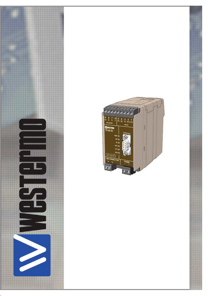
TD-29 DC
Westermo Teleindustri AB
©
FSK-modem
Multidrop 2-wire
www.westermo.com
Page 2

2
6611-2002
Legal information
The contents of this document are provided “as is”. Except as required by applicable
law, no warranties of any kind, either express or implied, including, but not limited to,
the implied warranties of merchantability and fitness for a particular purpose, are made
in relation to the accuracy and reliability or contents of this document. Westermo
reserves the right to revise this document or withdraw it at any time without prior
notice.
Under no circumstances shall Westermo be responsible for any loss of data or income
or any special, incidental, and consequential or indirect damages howsoever caused.
More information about Westermo can be found at the following Internet address:
http://www.westermo.com
Page 3
3
6611-2002
Safety
!
!
!
General:
Before using this unit, read this manual completely and gather all information on
the unit. Make sure that you understand it fully. Check that your application does
not exceed the safe operating specifications for this unit.
Before installation, maintenance or modification work:
Prevent damage to internal electronics from electrostatic discharges (ESD)
by discharging your body to a grounding point (e.g. use of wrist strap).
Prevent access to hazardous voltages by disconnecting the unit from DC
power supply and all other electrical connections.
Installation:
This unit should only be installed by qualified personnel.
This unit should only be installed in a “restricted access area”, for example a
lockable cabinet where access is restricted to service personnel only.
This unit is intended for permanent connection to the DC power supply.
The power supply wiring must be sufficiently fused, and if necessary it must be
possible to disconnect manually from the DC power supply. Ensure compliance to
national installation regulations.
Units with the rated voltage up to 42.4 V peak or 60 VDC, are defined as class III
equipment and shall be separated from hazardous voltage by double or reinforced
insulation.
This unit uses convection cooling. To avoid obstructing the air flow around the unit,
follow the spacing recommendations (see Installation section on page 13).
The TD-29 is designed to be used on dedicated lines and is not
approved to European standard CTR-15 (2-wire leased line).
Maintenance
No maintenance is required, as long as the unit is used as intended within the specified
conditions.
Agency approvals and standards compliance
Type Approval / Compliance
EMC
2004/108/EC, Electromagnetic compatibility
EN 61000-6-2, Immunity industrial environments
61000-6-4, Emission residential environments
Page 4
4
6611-2002
Declaration of Conformity
Westermo T eleindustri AB
Declaration of conformity
Org.nr/
Postadress/Postal address
Tel.
Telefax
Postgiro
Bankgiro Corp. identity number Registered office
S-640 40 Stora Sundby 016-428000 016-428001 52 72 79-4 5671-5550 556361-2604 Eskilstuna
Sweden Int+46 16428000 Int +46 16428001
The manufacturer
Westermo Teleindustri AB
SE-640 40 Stora Sundby, Sweden
Herewith declares that the product(s)
Type of product Model Art no
Multidrop FSK-modem TD-29 DC 3611-0001
is in conformity with the following EC directive(s).
No Short name
2004/108/EC Electromagnetic Compatibility (EMC)
2011/65/EU Restriction of the use of certain hazardous substances in electrical and
electronic equipment (RoHS)
References of standards applied for this EC declaration of conformity.
No Title Issue
EN 61000-6-2 Electromagnetic compatibility – Immunity for
industrial environments
2005
EN 61000-6-4 Electromagnetic compatibility – Emission for
industrial environments
2007
+A1:2011
The last two digits of the year in which the CE marking was affixed: 13
Pierre Öberg
Technical Manager
27
th
March 2013
Page 5
5
6611-2002
Description
The TD-29 is designed for communication on 2-wire copper cable (twisted pair).
Multidrop or point to point is possible.The TD-29 will support half duplex at baud rates
up to 19.2 kbit/s.
The TD-29 is easy to configure for different operating conditions with DIP-switches.
Character formats, baud rate, transmission level, DCD detection level and communication
interface are selectable. DTE-equipment can be connected through an RS-232 or
an RS-422/485 interface.The RS-232 connection can be made through either the DB-9
connector or screw terminal on the front of the unit.There are four baud rate settings.
When using the RS-232 interface the direction of communication can be controlled by
RTS handshake signal or incoming data.
When connecting in multidrop configuration the maximum bus length depends on the
number of units connected. (see below)
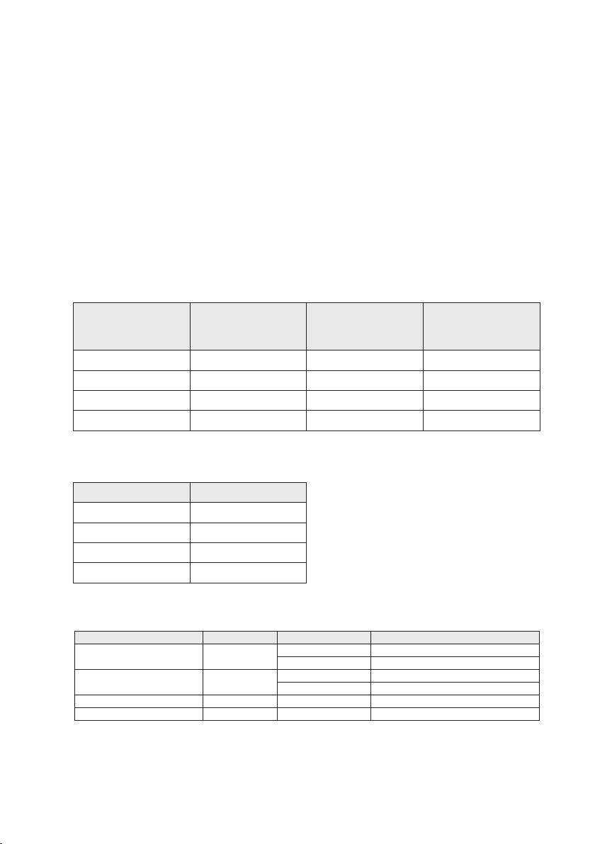
Maximum range and signal loss
Transmission speed
(bit/s)
2 400 16 1.5 0.2
4 800 14 1.7 0.2
9 600 11 2.1 0.3
19 200 9 2.5 0.4
Measured with Cat. 5 cable UTP 4x2x24AWG. Signal level >–24 dBm. The bus length depends on the line quality.
Turning time (RS-485)
Data rate bit/s Turning time µs
2 400 800
4 800 400
9 600 320
19 200 300
Range
point-to-point
(km)
Signal loss
(dB/km)
Loss per unit
(multidrop) (dB)
Environmental conditions
Environmental phenomena Basic standard Description Test levels
Temperatures Operating 5 to +50°C (41 to +122°F)*
Storage and transport –40 to +85°C (–40 to +185°F)
Humidity Operating 5 to 95 % relative humidity
Storage and transport 5 to 95 % relative humidity
Altitude Operating 2 000 m / 70 kPa
Service life Operating 10 year
Page 6

6
6611-2002
Interface specifications
Power TD-29 DC
Rated voltage 24 VDC
Operating voltage 12–36 VDC
Rated current 200 mA
Rated frequency –
Connection 2-pos. screw term.
Connector size 0.2–2.5 mm² (AWG 24-12)
RS-422/485
Electrical specification RS-422/485
Data rate 2 400 bit/s–19.2 kbit/s
Connection 5-position screw terminal
Connector size 0.2–2.5 mm² (AWG 24-12)
Circuit type TNV-1, twisted pair, shielding not required
RS-232
Electrical specification RS-232
Data rate 2 400 bit/s–19.2 kbit/s
Connection 9 position D-sub, DCE
Circuit type SELV, max 15 m length, shielding not required
Line interface
Electrical specification –
Data rate 2 400 bit/s–19.2 kbit/s
Connection 2 position screw terminal
Connector size 0,2–2,5 mm² (AWG 24-12)
Circuit type TNV-3
Page 7

7
6611-2002
Connections
RS-422/RS-485
4-pos screw terminal
(see next page)
LED indicators
(see below)
Line connection
(see next page)
RS-232
5-pos screw terminal
(see next page)
9-pos D-sub
RS-232
(see next page)
Power supply
(see next page)
LED Indicators
LED Status Description
PWR LED on
LED off
RD LED on
LED off
TD LED on
LED off
RTS LED on
LED off
DCD LED on
LED off
CTS LED on
LED off
Power on
Power off
Receive Line Data active
Transmit Line Data active
Receive Line Data inactive
Request To Send active
Request To Send inactive
Data Carrier Detect active
Data Carrier Detect inactive
Clear To Send active
Clear To Send inactive
Page 8

8
6611-2002
Interface RS-232
5
4
3
2
1
9
8
7
6
56789 4 3
2
1
56789 4 3
2
1
1
2
1
2
9-pos. D-sub
Pin. no.
1 – – –
2 4 Out RD/Received Data
3 3 In TD/Transmitted
4 – – –
5 5 – SG/Signal Ground
6 – Out DSR/Data Set Ready
7 2 In RTS/Request to Send
8 1 Out CTS/Clear to Send
9 – – –
9-pos.
Screw terminal
Direction Description
Data
Interface RS-422/485
9-pos.
Screw
Direction
terminal
9 In A' (R+) RS-422 Receiver
8 Out B' (R–) RS-422 Receiver
7 In/Out A (T+) RS-422/485
6 In/Out B (T–) RS-422/485
The definition of R+/R–, T+T– can vary between different manufacturers.
ITU-T V.11
Description
Description
Transmitter/Receiver
Transmitter/Receiver
Line interface
2-pos.
screw terminal
1 In/Out Transmitter/Receiver
2 In/Out (2-wire)
Direction Description
Power connection DC
Screw no. Description Power supply
1 – 0 V DC
2 + 12–36 VDC
Page 9

9
6611-2002
Configuration
S2:1–4
S1:1–8
1 2 3 4 5 6 7 8 9
!
!
DIP switch settings
DIP-switches are accessable under the lid on top of the unit. DIP-switches are used to
configure the modem.
Warning!
Prevent damage to internal electronics from electrostatic discharges (ESD)
by discharging your body to a grounding point (e.g. use of wrist strap),
before the lid on top of the modem is removed.
Warning! Do not open connected equipment.
Prevent access to hazardous voltages by disconnecting the unit from
DC power supply and all other electrical connections.
NOTE
When configuring via DIP-switches, the settings of DIP-switches configure the unit only
after a power reset. A setting configured by any other method during normal
operation, overrides the DIP-switch setting. However, at power up, the DIP-switch
settings have precedence over the setting configured by any other method.
Page 10

10
6611-2002
Switch block 1 – S1
Character format
ON
S1
1 2 3 4 5 6 7 8
ON
S1
1 2 3 4 5 6 7 8
10 bit/s
11 bit/s
Selection of Baud rate
ON
S1
1 2 3 4 5 6 7 8
ON
S1
1 2 3 4 5 6 7 8
ON
S1
1 2 3 4 5 6 7 8
ON
S1
1 2 3 4 5 6 7 8
2 400 bit/s
4 800 bit/s
9 600 bit/s
19.2 kbit/s
Termination of the line*
ON
S1
1 2 3 4 5 6 7 8
ON
S1
1 2 3 4 5 6 7 8
No
termination
Termination
Carrier active using
RTS or incoming data
ON
S1
1 2 3 4 5 6 7 8
ON
S1
1 2 3 4 5 6 7 8
Data
RTS
Selection of transmission level*
ON
S1 –9 dBm
1 2 3 4 5 6 7 8
ON
S1
1 2 3 4 5 6 7 8
5 dBm
* Load 600 Ω
Selection of
minimum detection level
ON
S1 –30 dBm
1 2 3 4 5 6 7 8
ON
S1
1 2 3 4 5 6 7 8
–20 dBm
* The line should be terminated at the end points.
S1: 8 not used
Switch block 2 – S2
Termination of RS-422*
ON
S2
1 2 3 4
ON
S2
1 2 3 4
No termination
Termination
* The line should be terminated at the end points. * The line should be terminated at the end points.
Factory setting
ON
S1
1 2 3 4 5 6 7 8
Termination of RS-485*
ON
S2
1 2 3 4
ON
S2
1 2 3 4
ON
S2
1 2 3 4
No termination
Termination
Page 11

11
6611-2002
Functional description
Amplifier S1:6
S1:7
CTSRD TD SG RT S
RTS LED
CTS LED
TD LED
RD
LED
DCD
LED
DSR CTS RTS TD RD SG B A B’ A’
Screw terminalD-Sub
1 2 3 4 5 6 7 82 3 5
0V
0V
F1
0V
+5V
–5V
0V
S2:4
S2:3
S2:2
S2:1
5V
0V
5V
0V
5V
6 7 8 9
MCU
FSK
Demodulator
Isolated
Power Supply
S1:4
0V
0V
PWR
LED
Line
switch
Line
Power Supply
Block diagram
RS-422/485 connection
4-wire 2-wire
TD-29 TD-29
Receiver
Transmitter
NC NC
Twisted pair
9
A’
8
B’
7
A
6
B
5
RS-422
equipment
A
Transmitter
B
Receiver A/A’
A’
Transmitter/
Receiver
B’
Twisted pair
7
6
B/B’ B/B’
5
A/A’
RS-485
equipment
Transmitter/
Receiver
Page 12

12
6611-2002
1�2�3�4�5�6�7�
8�
9�
POWER�
LINE CONNECTION�
PWR�
TD�
RD�
RTS�
V24/RS-232-C�
CTS�
1�2�3�4�
5�6�
7�8�
9�
T- �T+�R-�R+�
TD-29 DC�
RS-422/485�
SG�RD� TD�
DCD�
+�
–�
RS-232�
RTS�CTS�
1�2�3�4�5�6�7�
8�
9�
POWER�
LINE CONNECTION�
PWR�
TD�
RD�
RTS�
V24/RS-232-C�
CTS�
1�2�3�4�
5�6�
7�8�
9�
T- �T+�R-�R+�
TD-29 DC�
RS-422/485�
SG�RD� TD�
DCD�
+�
–�
RS-232�
RTS�CTS�
1�2�3�4�5�6�7�
8�
9�
POWER�
LINE CONNECTION�
PWR�
TD�
RD�
RTS�
V24/RS-232-C�
CTS�
1�2�3�4�
5�6�
7�8�
9�
T- �T+�R-�R+�
TD-29 DC�
RS-422/485�
SG�RD� TD�
DCD�
+�
–�
RS-232�
RTS�CTS�
1234567
8
9
POWER
LINE CONNECTION
PWR
TD
RD
RTS
V24/RS-232-C
CTS
1234
56
78
9
T-T+R-R+
TD-29 DC
RS-422/485
SG RD TD
DCD
+
–�
RS-232
RTS CTS
Line connection
2-position
detachable screw terminal
Multidrop half duplex with TD-29
Termination to be set with DIP-switches
Page 13

13
6611-2002
CLICK!
Mounting
This unit should be mounted on 35 mm DIN-rail, which is
horizontally mounted inside an apparatus cabinet, or similar.
Snap on mounting, see figure.
Cooling
This unit uses convection cooling. To avoid
obstructing the airflow around the unit, use the
following spacing rules. Minimum spacing 25 mm
(1.0 inch) above /below and 10 mm (0.4 inches)
left /right the unit. Spacing is recommended for
the use of unit in full operating temperature
range and service life.
* Spacing (left/right) recommended for
full operating temperature range
10 mm *
(0.4 inches)
25 mm
25 mm
Removal
Press down the black support at the back of the unit
using a screwdriver, see figure.
Page 14

Page 15

Page 16

Westermo • SE-640 40 Stora Sundby, Sweden
Tel +46 16 42 80 00 Fax +46 16 42 80 01
Sales Units
Westermo Data Communications
E-mail: info@westermo.com
www.westermo.com
China
sales.cn@westermo.com
www.cn.westermo.com
France
infos@westermo.fr
www.westermo.fr
Germany
info@westermo.de
www.westermo.de
For complete contact information, please visit our website at www.westermo.com/contact
REV.A 6611-2002 2013-03 Westermo Teleindustri AB, Sweden – A Beijer Electronics Group Company
North America
info@westermo.com
www.westermo.com
Singapore
sales@westermo.com.sg
www.westermo.com
Sweden
info.sverige@westermo.se
www.westermo.se
or scan the QR code with your mobile phone.
United Kingdom
sales@westermo.co.uk
www.westermo.co.uk
Other Offices
 Loading...