

Page 1

User Guide
6644-2214
SDW-500
SERIES
Westermo Teleindustri AB
©
Industrial Ethernet
5-port Switch
www.westermo.com
Page 2

Legal information
The contents of this document are provided “as is”. Except as required by applicable
law, no warranties of any kind, either express or implied, including, but not limited to,
the implied warranties of merchantability and fitness for a particular purpose, are made
in relation to the accuracy and reliability or contents of this document. Westermo
reserves the right to revise this document or withdraw it at any time without prior
notice.
Under no circumstances shall Westermo be responsible for any loss of data or income
or any special, incidental, and consequential or indirect damages howsoever caused.
More information about Westermo can be found at the following Internet address:
http://www.westermo.com
2
6644-2214
Page 3

Safety
!
!
!
Before installation:
Read this manual completely and gather all information on the unit. Make sure that
you understand it fully. Check that your application does not exceed the safe operating specifications for this unit.
This unit should only be installed by qualified personnel.
This unit should be built-in to an apparatus cabinet, or similar, where access is
restricted to service personnel only.
The power supply wiring must be sufficiently fused, and if necessary it must be
possible to disconnect manually from the power supply. Ensure compliance
to national installation regulations.
This unit uses convection cooling.To avoid obstructing the air flow around the
unit, follow the spacing recommendations (see Installation section).
Before mounting, using or removing this unit:
Prevent access to hazardous voltage by disconnecting the unit from power supply.
Warning! Do not open connected unit. Hazardous voltage may occur within this
unit when connected to power supply.
Class 1 Laser Product
Do not look directly into fibre optical fibre port or any connected fibre although
this unit is designed to meet the Class 1 Laser regulations.
Care recommendations
Follow the care recommendations below to maintain full operation of unit and to fulfil
the warranty obligations.
This unit must not be operating with removed covers or lids.
Do not attempt to disassemble the unit. There are no user serviceable parts inside.
Do not drop, knock or shake the unit, rough handling above the specification may cause
damage to internal circuit boards.
Do not use harsh chemicals, cleaning solvents or strong detergents to clean the unit.
Do not paint the unit. Paint can clog the unit and prevent proper operation.
Do not expose the unit to any kind of liquids (rain, beverages, etc). The unit is not water-
proof. Keep the unit within the specified humidity levels.
Do not use or store the unit in dusty, dirty areas, connectors as well as other mechanical
part may be damaged.
If the unit is not working properly, contact the place of purchase, nearest Westermo dis-
tributor office or Westermo Tech support.
Fibre connectors are supplied with plugs to avoid contamination inside the optical port.
As long as no optical fibre is mounted on the connector, e.g. for storage, service or
transportation, should the plug be applied.
6644-2214
3
Page 4
ATEX Information (Applicable for SDW-500 Ex series only)
General
This unit is intended for use in Zone 2 hazardous location only.
Marking
II 3 G
Ex nA IIC 140°C (T3) Gc
SPECIAL CONDITION
WARNING – DO NOT SEPARATE WHEN ENERGIZED
Indicate that this unit complies with relevant European standards that are
harmonised with the 94/9/EC Directive (ATEX).
II
3
G
Ex Indicates that this unit is in conformity with relevant European Ex standard(s).
nA
IIC Gas group, a typical gas i hydrogen.
140°C (T3)
Gc
SPECIAL
CONDITION
Equipment group II.
This unit can be installed in all places with an explosive gas atmosphere other
than mines susceptible to firedamp.
Equipment category 3.
A category is the classification according to the required level of protection.
This unit ensures the requisite level of protection during normal operation and
is intended for use in areas in which explosive atmosphere caused by gases,
vapours, mists, or dust mixtures are unlikely to occure or, if they do occure, are
likely to do so only infrequently and for a short periode only.
Indicates protection concerning explosive atmospheres caused by gases,
vapours or mists (G).
The type of protection used.
This unit is a non-sparking device "nA" which is constructed to minimize the
risk of occurence of arcs or sparks capable of creating an ignition hazard during
conditions of normal operation.
Maximum surface temperature assigned = 140°C with the next highest temperature class T3 (T3 = 200°C).
This unit is classified in accordance with its maximum surface temperature
(external and internal).
Equipment protection level Gc (EPL Gc)
Equipment for explosive gas atmospheres, having a "enhanced" level of protection, which is not a source of ignition in normal operation and which may have
some additional protection to ensure that it remains inactive as an ignition
source in the case of regular expected occurences. EPL Gc are analogous to
the ATEX Categories (Category 3 G = EPL Gc).
This unit has a special condition for safe use.
The special condition for safe use contains safety related information that is
necesarry for the correct installation and safe use.
4
6644-2214
Page 5

Ratings and safety control drawing
Ratings \ Model SDW-550EX
Power (12 – 48) VDC; 320 mA (12 – 48) VDC; 350 mA (12 – 48) VDC; 450 mA
Ambient temperature –25ºC ≤ Ta ≤ +70ºC –25ºC ≤ Ta ≤ +65ºC
Maximum surface
temperatur
Degree of protection IP 21
Installation spacing Minimum 25 mm above / below and minimum 10 mm left / right
SDW-532EX-2SM-LC15
Ratings \ Model
Power (12 – 48) VDC; 450 mA (12 – 48) VDC; 600 mA
Ambient temperature –25ºC ≤ Ta ≤ +60ºC
Maximum surface
temperatur
Degree of protection IP 21
Installation spacing Minimum 25 mm above / below and minimum 10 mm left / right
SDW-532EX-2MM-LC2
SDW-532EX-2SM-SC15
SDW-532EX-2SM-LC40
SDW-541EX-MM-LC2
SDW-541EX-SM-SC15
SDW-541EX-SM-LC40
140ºC (temperatur class T3)
SDW-532EX-2MM-SC2
SDW-532EX-2MM-ST2
140ºC (temperatur class T3)
SDW-541EX-MM-SC2
SDW-541EX-MM-ST2
SDW-541EX-SM-LC15
Ethernet TX – RJ 45
Position
1 In / Out / TD+
2 In / Out / TD–
3 In / Out / RD+
4 Not connected
5 Not connected
6 In / Out / RD–
7 Not connected
8 Not connected
Shield HF-connected
Galvanically isolated via signal transformers and capacitively isolated
to signal ground through 3 kV 470 pF capacitor.
Direction* /
descripton
Input / Output values
Per port:
U = ± 1 V (4μV/s)
I = ± 20 mA
Data rate:
10/100 Mbit/s
Ethernet FX – SC, ST or LC
Position
Rx In / Receive port
Tx Out / Transmit port
Direction* /
descripton
Input / Output values
Max optical power = 5 dBm
Power
Direction* /
descripton
Input / Output values
Uin = (9.6 – 57.6) VDC
Max Iin = 0.6 A @ 9.6 VDC
Max Pin = 6 W
The different models allows these
ports to be configured as either
copper RJ 45, optical SC, -ST or
-LC connection.
Position
1 In / COM
2 In / +VA
3 In / +VB
6644-2214
5
Page 6

SPECIAL CONDITION FOR SAFE USE
Ambient temperature:
This unit is designed for use in extreme ambient temperature conditions according to the following:
SDW-550: –25ºC ≤ Ta ≤ +70ºC
SDW-541: –25ºC ≤ Ta ≤ +65ºC
SDW-532: –25ºC ≤ Ta ≤ +60ºC
Installation in an apparatus cabinet:
This unit requires installation in an Ex certified apparatus cabinet suitable for the area of use and
providing a degree of protection of at least IP54.
Resistance to impact:
This unit requires installation in an apparatus cabinet where adequate resistance to impact is
provided by the apparatus cabinet. See "Installation in an apparatus cabinet" above for requirements
on the external apparatus cabinet.
Resistance to light:
This unit requires installation in an apparatus cabinet where it is protected from light
(for example daylight or light from luminaires).
See "Installation in an apparatus cabinet" above for requirements on the external apparatus cabinet.
Secureness of plugs:
When this unit is installed in an explosive atmospheres, all connectors must be mechanically secured
to prevent loosening.
Conductor temperature:
When this unit is installed in locations with high ambient temperature, special precautions shall be
taken upon the choice of external conductors and the temperature rating of the conductor(s).
Directive 94/9/EC alongside with other directives:
Directive 2004/108/EC (EMC) applies and to assure a safe performance of this unit under the scope
of Directive 94/9/EC, refer to the electromagnetic immunity level specified under "Type tests and
environmental conditions" in this manual.
Standards and date of compliance
EN 60079-0 and EN 60079-15
2011-04-15
6
6644-2214
Page 7

Note. Fibre Optic Handling
Fibre optic equipment needs special treatment. It is very sensitive to dust and dirt. If
the fibre will be disconnected from the modem the protective hood on the transmitter/
receiver must be connected. The protective hood must be kept on during transportation.
The fibre optic cable must also be handle the same way.
If this recommendation not will be followed it can jeopardise the warranty.
Cleaning of the optical connectors
In the event of contamination, the optical connectors should be cleaned by the use of
forced nitrogen and some kind of cleaning stick.
Recommended cleaning fluids:
• Methyl-, ethyl-, isopropyl- or isobutyl-alcohol
• Hexane
• Naphtha
Maintenance
No maintenance is required, as long as the unit is used as intended within the specified
conditions.
Agency approvals and standards compliance
Type Approval / Compliance
EMC EN 61000-6-2, Immunity industrial environments
EN 61000-6-31, Emission residential environments
EN 61000-6-42, Emission industrial environments
E-Mark, Road Vehicles, 10R-04 7216
Safety UL 60950-1, 1st Edition
3
Marine DNV Standard for Certification no. 2.4
Ex EN 60079-0 and EN 60079-15
Note
1
– Applicable only for 3644-000x and 3644-0015
2
– Applicable only for 3644-0019, 3644-002x and 3644-003x
3
– Applicable only for 3644-000x (SDW-550 och SDW-550 EC)
4
– Applicable only for 3644-0001, 3644-0022 , 3644-0023, 3644-0025,
3644-0032, 3644-0033, 3644-0035
(SDW-550, SDW-532-MM-LC15, SDW-532-MM-LC2, SDW-532-SM-LC40,
SDW-532-2SM-LC15, SDW-532-2SM-LC2, SDW-532-2SM-LC40)
5
– Applicable only for SDW-5xx Ex series
6 _ Applicable only for 3644-6001 (SDW-550 E-mark)
6
4
5
6644-2214
7
Page 8
Declaration of Conformity
Westermo Teleindustri AB
Declaration of conformity
Org.nr/
Postadress/Postal address
Tel.
Telefax
Postgiro
Bankgiro Corp. identity number Registered office
S-640 40 Stora Sundby 016-428000 016-428001 52 72 79-4 5671-5550 556361-2604 Eskilstuna
Sweden Int+46 16428000 Int+46 16428001
The manufacturer
Westermo Teleindustri AB
SE-640 40 Stora Sundby, Sweden
Herewith declares that the product(s)
Type of product Model Art no
Industrial Ethernet switch SDW-500 series 3644-0001, -0005, -0015, -0019, -0020,-0021, -
0022, -0023, -0024, -0025, -0030,-0031, -0032, 0033, -0034, -0035
SDW-500 EX series 3644-5001 ,-5020, -5021, -5022, -5023,-5024, -
5025, -5030, -5031, -5032, -5033,-5034, -5035
SDW-550 E-mark 3644-6001
is in conformity with the following EC directive(s).
No Short name
2004/108/EC Electromagnetic Compatibility (EMC)
94/9/EC 1 Equipment Explosive Atmospheres (ATEX)
2011/65/EU Restriction of the use of certain hazardous substances in electrical and electronic
equipment (RoHS)
References of standards applied for this EC declaration of conformity.
No Title Issue
EN 61000-6-2 Electromagnetic compatibility – Immunity for industrial
environments
2005
EN 61000-6-3 2 Electromagnetic compatibility – Emission for residential
environments
2007
EN 61000-6-4 3 Electromagnetic compatibility – Emission for industrial
environments
2007
EN 60079-0
1
Explosive atmospheres
Equipment – General requirements
2009
EN 60079-15
1
Electrical apparatus for explosive gas atmospheres –
Construction, test and marking of type of protection “n” electrical
apparatus
2005
The last two digits of the year in which the CE marking was affixed: 14
Pierre Öberg
Technical Manager
12
th
Mars 2014
1
Applicable for SDW-500 EX series.
2
Applicable for 3644-000x, 3644-0015 and 3644-6001
3
Applicable for 3644-0019, 3644-002x and 3644-003x.
8
6644-2214
Page 9

Environmental conditions
Isolation between interfaces
Power Interface to all other 2.8 kV DC 2.0 kV RMS @ 50 Hz and 60 s duration
TX signal Interface to all other 2.1 kV DC 1.5 kV RMS @ 50 Hz and 60 s duration
TX shield Interface to all other 1.5 kV DC 1.0 kV RMS @ 50 Hz and 60 s duration
Environmental
Temperature, operating –25 to +70°C (SDW-550),
Temperature, storage and transportation –25 to +70°C
Relative humidity, operating 5 to 95% (non-condensing)
Relative humidity,
storage and transportation
Altitude, operating 2000 m/70 kPa
Mechanical
Dimension (W x H x D) 35 x 121 x 119 mm
Weight 0.2 kg
Mounting DIN-rail
Degree of protection IP21
Configuration
Auto configured (auto-negotiation) or manually setting of speed and duplex of individual TX port,
by DIP-switches.
Port mirror function is possible to set with DIP-switch. With the port mirror function active
the switch will copy all outgoing traffic to port 1. This can be used to monitor all traffic going
out from the switch. Packets may be discarded if the total throughput exceeds the port speed
of port 1.
–25 to +65°C (SDW-541)
–25 to +60°C (SDW-532)
5 to 95% (condensation allowed outside packaging)
Fibre optic power budget
Model Multimode
Transmitted wavelength 1310 nm 1310 nm 1310 nm 1310 nm
Min. output power, transmitter –19 dBm –15 dBm –15 dBm –5 dBm
Max. output power, transmitter –12 dBm –8 dBm -8 dBm 0 dBm
Input sensitivity, receiver –31 dBm –34 dBm –31 dBm –34 dBm
Min. power budget 12 dBm 19 dBm 16 dBm 29 dBm
Max. power budget 19 dBm 26 dBm 23 dBm 34 dBm
Recommended fibre cable and
core / cladding diameter
MM-xx2
50/125
62.5/125
Singlemode
SM-SC15
9/125
10/125
Singlemode
SM-LC15
9/125
10/125
Singlemode
SM-LC40
9/125
10/125
Attenuation in connectors / splices
Type Normal attenuation
Connector 0.2 - 0.4 dBm
Fusion splice 0.1 dBm
Mechanical splice 0.2 dBm
6644-2214
9
Page 10

Description
The SDW-550 is an Industrial Ethernet 5-port switch.
All ports support auto-negotiation, but DIP-switches also allow speed and duplex
configuration of any individual TX port. It is also possible to set up one port to
monitor traffic to/from the switch.
The SDW-550 has been designed to meet high industrial specifications, providing
very high dependability in harsh environmental conditions.
Features:
… TX shields individually isolated
… Wide DC power range 12 – 48 VDC
… Wide temperature range
… Automatic MDI/MDI-X crossover
… LED indicators for Power, Speed, Duplex, Link and Traffic
… Port monitoring
… 35 mm DIN rail mounting
… Enable or disable of flow control
Example of applications are:
… 5-port switch
… Ethernet isolator, for STP networks
10
6644-2214
Page 11
Interface specifications
Power SDW-500 series
Rated voltage 12 –48 VDC, polarity protected
Operating voltage 9.6 – 57.6 VDC
Rated current @12 VDC power input
SDW-550 320 mA
SDW-541-MM-SC2 450 mA
SDW-541-MM-ST2 450 mA
SDW-541-SM-LC15 450 mA
SDW-541-SM-SC15 350 mA
SDW-541-SM-LC40 350 mA
SDW-541-MM-LC2 350 mA
SDW-532-2-MM-SC2 600 mA
SDW-532-2-MM-ST2 600 mA
SDW-532-2-SM-LC15 450 mA
SDW-532-2-SM-SC15 450 mA
SDW-532-2-SM-LC40 450 mA
SDW-532-2-MM-LC2 450 mA
SDW-532-MM-SC2-SM-SC15 450 mA
Rated frequency DC
Connection Detachable screw terminal
Connector size 0.2 – 2.5 mm² (AWG 24-12)
Ethernet TX
Electrical specification IEEE std 802.3. 2000 edition
Data rate 10 Mbit/s or 100 Mbit/s, manual or auto
Duplex Full or half, manual or auto
Connection SC, ST or LC
Circuit type Optical
Transmission range 100 m
Ethernet FX
Electrical specification IEEE std 802.3. 2000 edition
Data rate 10 Mbit/s or 100 Mbit/s, manual or auto
Duplex Full or half, manual or auto
Connection SC, ST or LC
Circuit type Optical
Transmission range 100 m
6644-2214
11
Page 12

Connections
Network
RJ-45 connection
Power connection
LED indicators
Network
Fibre connection
or RJ-45 connection
Available models:
… SDW-550 10/100Base-T/TX: 5 ports
… SDW-541 10/100Base-T/TX: 4 ports 100Base-FX: 1 port
… SDW-532 10/100Base-T/TX: 3 ports 100Base-FX: 2 ports
NOTE! SDW-532-MM-SC2-SM-SC15
Port 4: SC Single mode 15 km connector
Port 5: SC Multi mode 2 km connector
12
6644-2214
Page 13

Power
8
7
6
5
4
3
2
1
The SDW-500 series supports redundant power connection.
The positive input are +VA and +VB, the negative input
for both supplies are COM.
The power is drawn from
the input with the highest
voltage.
3-pos screw terminal
1 COM 0 V
2 +VA A: 9.6 – 57.6 VDC
3 +VB B: 9.6 – 57.6 VDC
Description Power
12 3
TX
Ethernet TX connection (RJ-45 connector), automatic MDI/MDI-X crossover.
Contact Signal Name Direction Description/Remark
1 TD+ In/Out Transmitted/Received data
2 TD– In/Out Transmitted/Received data
3 RD+ In/Out Transmitted/Received data
4 – – –
5 – – –
6 RD– In/Out Transmitted/Received data
7 – – –
8 – – –
Shield – – HF-connected
CAT 5 cable is recommended.
Unshielded (UTP) or shielded (STP) connector might be used.
FX SC Multi- or single mode (optional)
Ethernet FX connection.
1300 nm multi- or singlemode fibre tranceiver with SC-connector.
The dust protection plug shall be mounted when no fibre is connected.
FX ST Multi mode (optional)
Ethernet FX connection.
1300 nm multi mode fibre tranceiver with ST-connector.
The dust protection plugs shall be mounted when no fibre is connected.
FX LC Multi- or single mode (optional)
Ethernet FX connection.
1300 nm singlemode fibre transceiver with LC-connector.
The dust protection plug shall be mounted when no fibre is connected.
6644-2214
13
Page 14

LED indicators
At power on the PWR flashes during initialising.
Indicators (LED) Power (PWR)
Link (LINK) of every port
Speed (SPD) and duplex (DPX) of TX ports
LED Status Indication of
PWR ON Internal power, initialising OK
Slow flash Initialisation progressing
Fast flash Initialisation error
LINK OFF No Ethernet link
ON Good Ethernet link
Flash Ethernet data is transmitted or received, traffic indication
SPD OFF 10 Mbit/s
(TX only) ON 100 Mbit/s
DPX OFF Half duplex
(TX only) ON Full duplex
14
6644-2214
Page 15
DIP switch settings SDW-550
DIP-switches are accessible under the lid on top of the unit. DIP-switches are
used to configure the unit.
Warning!
!
Prevent damage to internal electronics from electrostatic discharges (ESD) by
discharging your body to a grounding point (e.g. use of wrist strap), before the
lid on top/front of the unit is removed.
Warning! Do not open connected equipment.
!
Prevent access to hazardous voltages by disconnecting the unit from AC/DC mains
supply and all other electrical connections.
NOTE
When configuration via DIP-switches, the settings of DIP-switches configure the unit only
after a reboot (power off/on).
To be observe when the DIP-switches will be configured
… Speed and duplex setting only valid when auto-negotiation is disabled.
… When monitoring selected all outgoing packets from the switch is also copied to the
port 1.
… Speed and duplex switch settings are ignored for FX ports.
… If auto-negotiation and auto MDI/MDI-X disabled all TX ports support MDI-X
configuration.
6644-2214
15
Page 16
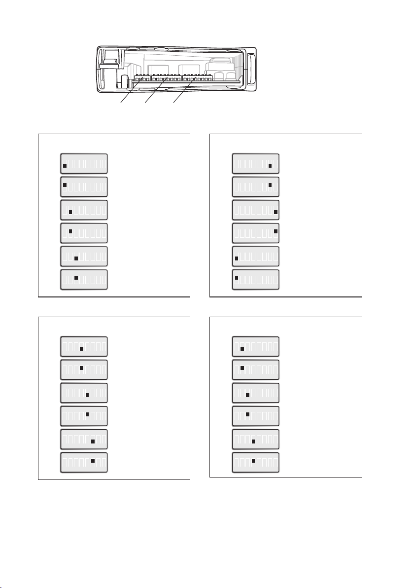
S3 S2
S1
ON
S1
1 2 3 4 5 6 7 8
ON
S1
1 2 3 4 5 6 7 8
ON
S1
1 2 3 4 5 6 7 8
ON
S1
1 2 3 4 5 6 7 8
ON
S1
1 2 3 4 5 6 7 8
ON
S1
1 2 3 4 5 6 7 8
ON
S1
1 2 3 4 5 6 7 8
ON
S1
1 2 3 4 5 6 7 8
ON
S1
1 2 3 4 5 6 7 8
ON
S1
1 2 3 4 5 6 7 8
ON
S1
1 2 3 4 5 6 7 8
ON
S1
1 2 3 4 5 6 7 8
Port 1 settings
Auto-negotiation and
auto MDI/MDI-X disabled
Auto-negotiation and
auto MDI/MDI-X enabled
10 Mbit/s speed selected
100 Mbit/s speed selected
Half duplex selected
Full duplex selected
Port 2 settings
Auto-negotiation and
auto MDI/MDI-X disabled
Auto-negotiation and
auto MDI/MDI-X enabled
10 Mbit/s speed selected
100 Mbit/s speed selected
Half duplex selected
Full duplex selected
ON
S1
1 2 3 4 5 6 7 8
ON
S1
1 2 3 4 5 6 7 8
ON
S1
1 2 3 4 5 6 7 8
ON
S1
1 2 3 4 5 6 7 8
ON
S2
1 2 3 4 5 6 7 8
ON
S2
1 2 3 4 5 6 7 8
ON
S2
1 2 3 4 5 6 7 8
ON
S2
1 2 3 4 5 6 7 8
ON
S2
1 2 3 4 5 6 7 8
ON
S2
1 2 3 4 5 6 7 8
ON
S2
1 2 3 4 5 6 7 8
ON
S2
1 2 3 4 5 6 7 8
Port 3 settings
Auto-negotiation and
auto MDI/MDI-X disabled
Auto-negotiation and
auto MDI/MDI-X enabled
10 Mbit/s speed selected
100 Mbit/s speed selected
Half duplex selected
Full duplex selected
Port 4 settings
Auto-negotiation and
auto MDI/MDI-X disabled
Auto-negotiation and
auto MDI/MDI-X enabled
10 Mbit/s speed selected
100 Mbit/s speed selected
Half duplex selected
Full duplex selected
16
6644-2214
Page 17

ON
S2
1 2 3 4 5 6 7 8
ON
S2
1 2 3 4 5 6 7 8
ON
S2
1 2 3 4 5 6 7 8
ON
S2
1 2 3 4 5 6 7 8
ON
S2
1 2 3 4 5 6 7 8
ON
S2
1 2 3 4 5 6 7 8
ON
S1
1 2 3 4 5 6 7 8
Port 5 settings
Auto-negotiation and
auto MDI/MDI-X disabled
Auto-negotiation and
auto MDI/MDI-X enabled
10 Mbit/s speed selected
100 Mbit/s speed selected
Half duplex selected
Full duplex selected
Port mirroring settings
ON
S2
1 2 3 4 5 6 7 8
ON
S2
1 2 3 4 5 6 7 8
Flow control selected
ON
S3
1 2 3 4
ON
S3
1 2 3 4
Flow control selected
No flow control selected
Factory settings
ON
S2 S3
1 2 3 4 5 6 7 8
No monitoring selected
Monitoring selected
ON
1 2 3 4
6644-2214
17
Page 18
DIP switch settings SDW-541 and SDW-532
DIP-switches are accessible under the lid on top of the unit. DIP-switches are
used to configure the unit.
Warning!
!
Prevent damage to internal electronics from electrostatic discharges (ESD) by
discharging your body to a grounding point (e.g. use of wrist strap), before the
lid on top/front of the unit is removed.
Warning! Do not open connected equipment.
!
Prevent access to hazardous voltages by disconnecting the unit from AC/DC mains
supply and all other electrical connections.
NOTE
When configuration via DIP-switches, the settings of DIP-switches configure the unit only
after a reboot (power off/on).
To be observe when the DIP-switches will be configured
… Speed and duplex setting only valid when auto-negotiation is disabled.
… When monitoring selected all outgoing packets from the switch is also copied to the
port 1.
… Speed and duplex switch settings are ignored for FX ports.
… If auto-negotiation and auto MDI/MDI-X disabled all TX ports support MDI-X
configuration.
18
6644-2214
Page 19

S1
S1
S2
S1
S1
S1
S1
S1
S1
S1
S1
S1
S1
S1
S1
S1
S1
S1
S2
S2
Port 1 settings
ON
1 2 3 4 5 6 7 8
ON
1 2 3 4 5 6 7 8
ON
1 2 3 4 5 6 7 8
ON
1 2 3 4 5 6 7 8
ON
1 2 3 4 5 6 7 8
ON
1 2 3 4 5 6 7 8
Port 2 settings
ON
1 2 3 4 5 6 7 8
ON
1 2 3 4 5 6 7 8
ON
1 2 3 4 5 6 7 8
ON
1 2 3 4 5 6 7 8
ON
1 2 3 4 5 6 7 8
ON
1 2 3 4 5 6 7 8
Port 3 settings
ON
1 2 3 4 5 6 7 8
ON
1 2 3 4 5 6 7 8
ON
1 2 3 4 5 6 7 8
ON
1 2 3 4 5 6 7 8
ON
1 2 3 4 5 6 7 8
ON
1 2 3 4 5 6 7 8
Auto-negotiation and
auto MDI/MDI-X disabled
Auto-negotiation and
auto MDI/MDI-X enabled
10 Mbit/s speed selected
100 Mbit/s speed selected
Half duplex selected
Full duplex selected
Auto-negotiation and
auto MDI/MDI-X disabled
Auto-negotiation and
auto MDI/MDI-X enabled
10 Mbit/s speed selected
100 Mbit/s speed selected
Half duplex selected
Full duplex selected
Auto-negotiation and
auto MDI/MDI-X disabled
Auto-negotiation and
auto MDI/MDI-X enabled
10 Mbit/s speed selected
100 Mbit/s speed selected
Half duplex selected
Full duplex selected
Port 4 settings*
ON
S2
1 2 3 4 5
ON
S2
1 2 3 4 5
ON
S2
1 2 3 4 5
ON
S2
1 2 3 4 5
ON
S2
1 2 3 4 5
ON
S2
1 2 3 4 5
* Setting of port 4 is only possible when using
SDW-541.
These settings are ignored when using SDW-532
Auto-negotiation and auto MDI/
MDI-X disabled
Auto-negotiation and auto MDI/
MDI-X enabled
10 Mbit/s speed selected
100 Mbit/s speed selected
Half duplex selected
Full duplex selected
Port mirroring settings
S2
S2
ON
1 2 3 4 5
ON
1 2 3 4 5
No monitoring selected
Monitoring selected
Factory settings
ON
S1 S2
1 2 3 4 5 6 7 8
ON
1 2 3 4 5
6644-2214
19
Page 20
Installation
!
CLICK!
Mounting / Removal
Before mounting or removing the unit:
Prevent damage to internal electronics from electrostatic discharges (ESD)
by discharging your body to a grounding point (e.g. use of wrist strap).
Prevent access to hazardous voltages by disconnecting the unit from AC/DC mains
supply and all other electrical connections.
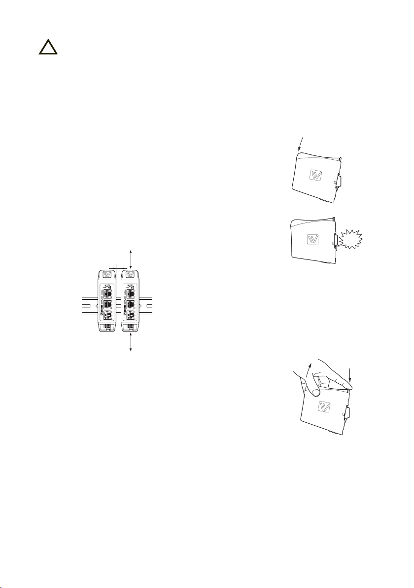
Mounting
This unit should be mounted on 35 mm DIN-rail which is horizontally mounted on a wall or cabinet backplate.
This unit uses convection cooling. To avoid obstructing the airflow
around the unit, use the following spacing rules.
Recommended spacing 25 mm (1.0 inch) above/below and 10 mm
(0.4 inches) left/right the unit.
Snap on mounting, see figure
10 mm *
(0.4 inches)
25 mm
* Spacing (left/right) recommended for
full operating temperature range
25 mm
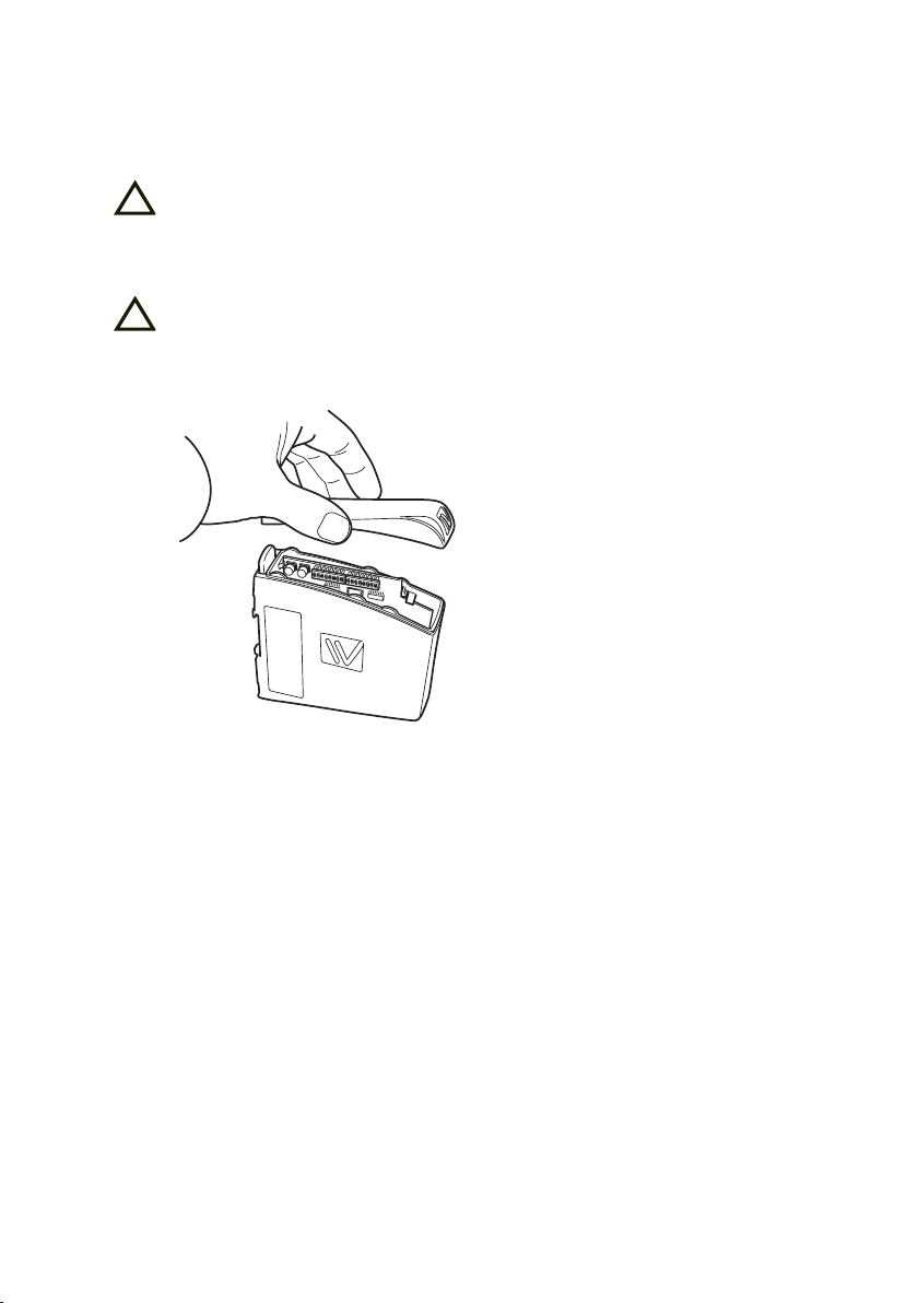
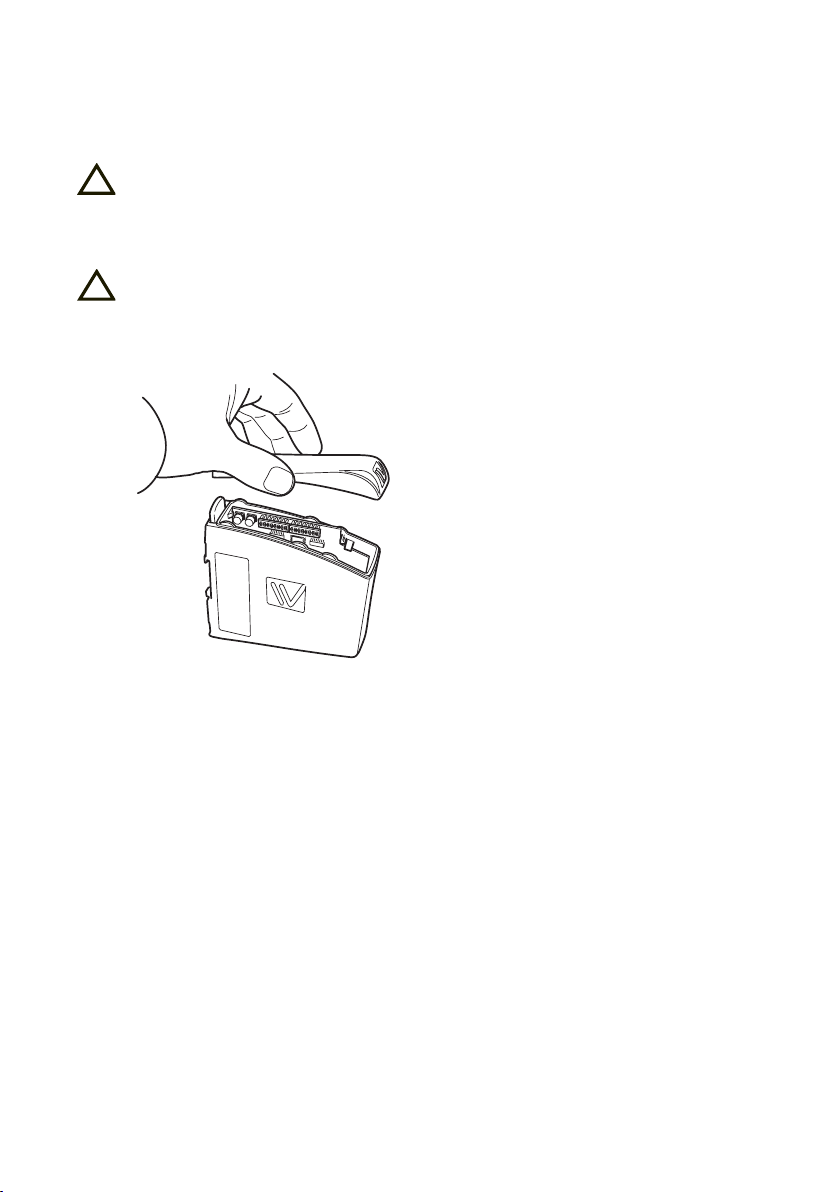
Removal
Press down the black support at the back of the unit, see figure.
20
6644-2214
Page 21

Page 22

Page 23

Page 24

Westermo • SE-640 40 Stora Sundby, Sweden
Tel +46 16 42 80 00 Fax +46 16 42 80 01
Sales Units
Westermo Data Communications
E-mail: info@westermo.com
www.westermo.com
China
sales.cn@westermo.com
www.cn.westermo.com
France
infos@westermo.fr
www.westermo.fr
Germany
info@westermo.de
www.westermo.de
For complete contact information, please visit our website at www.westermo.com/contact or scan the QR code
REV. D 6644-2214 2015-05 Westermo Teleindustri AB, Sweden – A Beijer Electronics Group Company
North America
info@westermo.com
www.westermo.com
Singapore
sales@westermo.com.sg
www.westermo.com
Sweden
info.sverige@westermo.se
www.westermo.se
United Kingdom
sales@westermo.co.uk
www.westermo.co.uk
Other Offices
 Loading...