

Westermo SDW-550 E-mark, SDW-541-MM-ST2, SDW-550B, SDW-532-MM-SC2-SM-SC15, SDW-541-MM-SC2 User Manual
...Page 1
©
Westermo Teleindustri AB
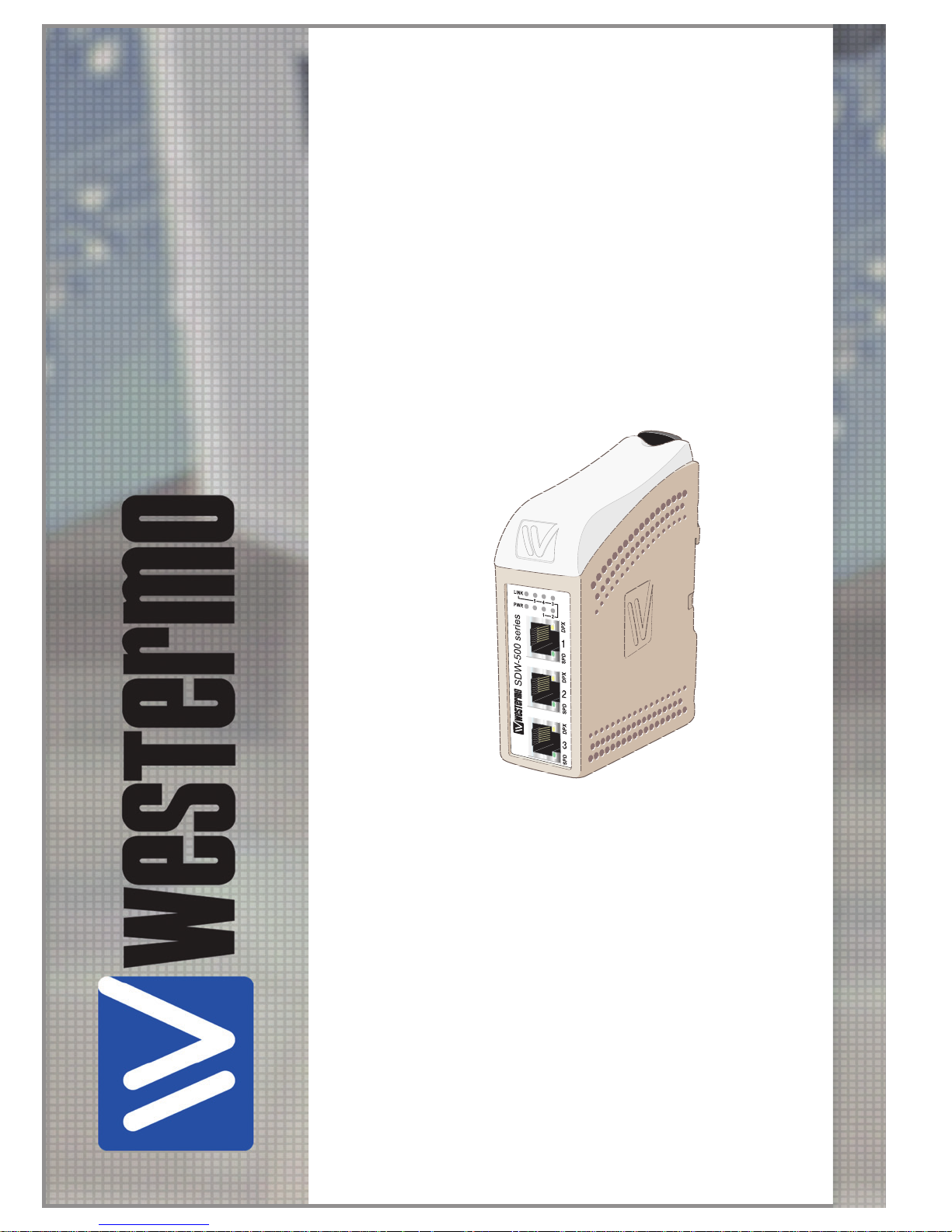
SDW-500
SERIES
User Guide
6644-2214
Industrial Ethernet
5-port Switch
www.westermo.com
Page 2

2
6644-2214
Legal information
The contents of this document are provided “as is”. Except as required by applicable
law, no warranties of any kind, either express or implied, including, but not limited to,
the implied warranties of merchantability and fitness for a particular purpose, are made
in relation to the accuracy and reliability or contents of this document. Westermo
reserves the right to revise this document or withdraw it at any time without prior
notice.
Under no circumstances shall Westermo be responsible for any loss of data or income
or any special, incidental, and consequential or indirect damages howsoever caused.
More information about Westermo can be found at the following Internet address:
http://www.westermo.com
Software tools
Related software tools are available in the folder software tools under
technical support on the Westermo website.
Page 3

3
6644-2214
Safety
Before installation:
Read this manual completely and gather all information on the unit. Make sure
that you understand it fully. Check that your application does not exceed the safe
operating specifications for this unit.
This unit should only be installed by qualified personnel.
This unit should be built-in to an apparatus cabinet, or similar, where access is
restricted to service personnel only.
The power supply wiring must be sufficiently fused, and if necessary it must be
possible to disconnect manually from the power supply. Ensure compliance to
national installation regulations.
This unit uses convection cooling.To avoid obstructing the air flow around the unit,
follow the spacing recommendations (see Installation section).
Before mounting, using or removing this unit:
Prevent access to hazardous voltage by disconnecting the unit from power supply.
Warning! Do not open connected unit. Hazardous voltage may occur within this
unit when connected to power supply.
Class 1 Laser Product
Do not look directly into fibre optical fibre port or any connected fibre although
this unit is designed to meet the Class 1 Laser regulations.
Care recommendations
Follow the care recommendations below to maintain full operation of unit and to fulfil
the warranty obligations.
This unit must not be operating with removed covers or lids.
Do not attempt to disassemble the unit. There are no user serviceable parts inside.
Do not drop, knock or shake the unit, rough handling above the specification may cause
damage to internal circuit boards.
Do not use harsh chemicals, cleaning solvents or strong detergents to clean the unit.
Do not paint the unit. Paint can clog the unit and prevent proper operation.
Do not expose the unit to any kind of liquids (rain, beverages, etc). The unit is not
waterproof. Keep the unit within the specified humidity levels.
Do not use or store the unit in dusty, dirty areas, connectors as well as other mechanical
part may be damaged.
If the unit is not working properly, contact the place of purchase, nearest Westermo
distributor office or Westermo Tech support.
Fibre connectors are supplied with plugs to avoid contamination inside the optical port.
As long as no optical fibre is mounted on the connector, e.g. for storage, service or
transportation, should the plug be applied.
!
!
!
Page 4

4
6644-2214
Note. Fibre Optic Handling
Fibre optic equipment needs special treatment. It is very sensitive to dust and dirt. If
the fibre will be disconnected from the modem the protective hood on the transmitter/
receiver must be connected. The protective hood must be kept on during transportation.
The fibre optic cable must also be handle the same way.
If this recommendation not will be followed it can jeopardise the warranty.
Cleaning of the optical connectors
In the event of contamination, the optical connectors should be cleaned by the use of
forced nitrogen and some kind of cleaning stick.
Recommended cleaning fluids:
• Methyl-, ethyl-, isopropyl- or isobutyl-alcohol
• Hexane
• Naphtha
Maintenance
No maintenance is required, as long as the unit is used as intended within the specified
conditions.
Page 5
5
6644-2214
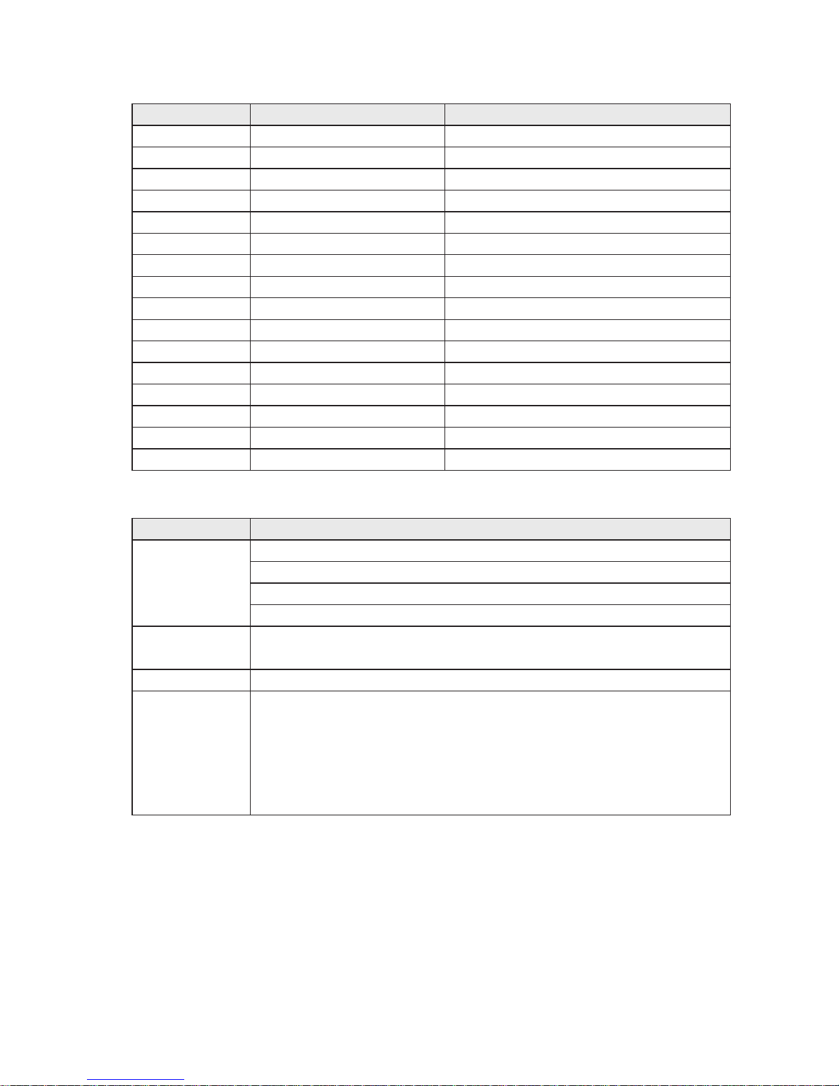
Agency approvals and standards compliance
Type Approval / Compliance
EMC EN 61000-6-2, Immunity industrial environments
EN 61000-6-31, Emission residential environments
EN 61000-6-42, Emission industrial environments
E-Mark, Road Vehicles, 10R-04 7216
3
Safety EN/IEC 60950-1, IT Equipment
UL 60950-1, IT Equipment 1st Edition
4
Marine DNV GL rules for classification – Ships and offshore units
5
Note 1 _ Applicable only for 3644-x001
2 _ Applicable only for 3644-0019, 3644-002x and 3644-003x
3
_ Applicable only for 3644-6001
4
– Applicable only for 3644-0001
5
– Applicable only for 3644-0001, 3644-0022 , 3644-0023, 3644-0025,
3644-0032, 3644-0033, 3644-0035
Article number, model and description
Article Model Description
3644-0001 SDW-550 10/100Base-T/TX: 5 ports
3644-6001 SDW-550 E-mark 10/100Base-T/TX: 5 ports
3644-0015 SDW-550B 10/100Base-T/TX: 5 ports
3644-0019 SDW-532-MM-SC2-SM-SC15 10/100Base-T/TX: 3 ports 100Base-FX: 2 port
3644-0020 SDW-541-MM-SC2 10/100Base-T/TX: 4 ports 100Base-FX: 1 port
3644-0021 SDW-541-MM-ST2 10/100Base-T/TX: 4 ports 100Base-FX: 1 port
3644-0022 SDW-541-SM-LC15 10/100Base-T/TX: 4 ports 100Base-FX: 1 port
3644-0023 SDW-541-MM-LC2 10/100Base-T/TX: 4 ports 100Base-FX: 1 port
3644-0024 SDW-541-SM-SC15 10/100Base-T/TX: 4 ports 100Base-FX: 1 port
3644-0025 SDW-541-SM-LC40 10/100Base-T/TX: 4 ports 100Base-FX: 1 port
3644-0030 SDW-532-MM-SC2 10/100Base-T/TX: 3 ports 100Base-FX: 2 port
3644-0031 SDW-532-MM-ST2 10/100Base-T/TX: 3 ports 100Base-FX: 2 port
3644-0032 SDW-532-SM-LC15 10/100Base-T/TX: 3 ports 100Base-FX: 2 port
3644-0033 SDW-532-MM-LC2 10/100Base-T/TX: 3 ports 100Base-FX: 2 port
3644-0034 SDW-532-SM-SC15 10/100Base-T/TX: 3 ports 100Base-FX: 2 port
3644-0035 SDW-532-SM-LC40 10/100Base-T/TX: 3 ports 100Base-FX: 2 port
Corrosive
environment
Notice:
This product has been successfully tested in a corrosion test according to
IEC 60068-2-60, method 3. This means that the product meets the requirements
to be placed in an environment classified as ISA-S71.04 class G3.
Note! If the product is placed in a corrosive environment, it is important that all
unused connector sockets are protected with a suitable plug in order to avoid
corrosion attacks on the gold plated pins in connectors.
Page 6
6
6644-2214
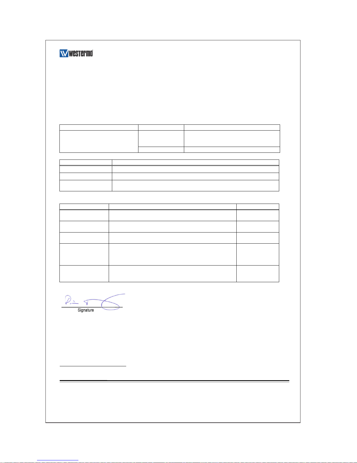
Declaration of Conformity
Westermo Teleindustri AB
Declaration of Conformity
Org.nr/
Postadress/Postal address
Tel.
Telefax
Postgiro
Bankgiro
Corp. identity number
Registered office
S-640 40 Stora Sundby
016-428000
016-428001
52 72 79-4
5671-5550
556361-2604
Eskilstuna
Sweden
Int+46 16428000
Int+46 16428001
The manufacturer
Westermo Teleindustri AB
SE-640 40 Stora Sundby, Sweden
Herewith declares that the product(s)
Type of product
Model
Art no
Industrial Ethernet switch
SDW-500 series
3644-0001, -0002, -0005, -0015, -0019, -0020,-
0021, -0022, -0023, -0024, -0025, -0030,-0031, -
0032, -0033, -0034, -0035
SDW-550 E-mark
3644-6001
is in conformity with the following EU directive(s).
No
Short name
2014/30/EU
Electromagnetic Compatibility (EMC)
2014/35/EU
Low Voltage Directive (LVD)
2011/65/EU
Restriction of the use of certain hazardous substances in electrical and electronic
equipment (RoHS)
References of standards applied for this EU declaration of conformity.
No
Title
Issue
EN 61000-6-2
Electromagnetic compatibility – Immunity for industrial
environments
2005
EN 61000-6-3
1
Electromagnetic compatibility – Emission for residential
environments
2007
EN 61000-6-4
2
Electromagnetic compatibility – Emission for industrial
environments
2007
EN 60950-1
Information technology equipment -- Safety -- General
requirements
2006
+A11:2009
+A1: 2010
+A12:2011
EN 50581
Technical documentation for the assessment of electrical and
electronic products with respect to the restriction of hazardous
substances
2012
The last two digits of the year in which the CE marking was affixed:
16
Pierre Öberg
Technical Manager
21stMarch 2016
1
Applicable for 3644-000x and 3644-6001
2
Applicable for 3644-0019, 3644-002x and 3644-003x.
Page 7

7
6644-2214
Environmental conditions
Isolation between interfaces
Power Interface to all other 2.8 kV DC 2.0 kV RMS @ 50 Hz and 60 s duration
TX signal Interface to all other 2.1 kV DC 1.5 kV RMS @ 50 Hz and 60 s duration
TX shield Interface to all other 1.5 kV DC 1.0 kV RMS @ 50 Hz and 60 s duration
Environmental
Temperature, operating –25 to +70°C (SDW-550),
–25 to +65°C (SDW-541)
–25 to +60°C (SDW-532)
Temperature, storage and transportation –25 to +70°C
Relative humidity, operating 5 to 95% (non-condensing)
Relative humidity,
storage and transportation
5 to 95% (condensation allowed outside packaging)
Altitude, operating 2000 m/70 kPa
Mechanical
Dimension (W x H x D) 35 x 121 x 119 mm
Weight 0.2 kg
Mounting DIN-rail
Degree of protection IP21
Configuration
Auto configured (auto-negotiation) or manually setting of speed and duplex of individual TX port,
by DIP-switches.
Port mirror function is possible to set with DIP-switch. With the port mirror function active the
switch will copy all outgoing traffic to port 1. This can be used to monitor all traffic going out
from the switch. Packets may be discarded if the total throughput exceeds the port speed of port
1.
Fibre optic power budget
Model Multimode
MM-xx2
Singlemode
SM-SC15
Singlemode
SM-LC15
Singlemode
SM-LC40
Transmitted wavelength 1310 nm 1310 nm 1310 nm 1310 nm
Min. output power, transmitter –19 dBm –15 dBm –15 dBm –5 dBm
Max. output power, transmitter –12 dBm –8 dBm -8 dBm 0 dBm
Input sensitivity, receiver –31 dBm –34 dBm –31 dBm –34 dBm
Min. power budget 12 dBm 19 dBm 16 dBm 29 dBm
Max. power budget 19 dBm 26 dBm 23 dBm 34 dBm
Recommended fibre cable and
core / cladding diameter
50/125
62.5/125
9/125
10/125
9/125
10/125
9/125
10/125
Attenuation in connectors / splices
Type Normal attenuation
Connector 0.2 - 0.4 dBm
Fusion splice 0.1 dBm
Mechanical splice 0.2 dBm
Page 8

8
6644-2214
Description
The SDW-550 is an Industrial Ethernet 5-port switch.
All ports support auto-negotiation, but DIP-switches also allow speed and duplex
configuration of any individual TX port. It is also possible to set up one port to monitor
traffic to/from the switch.
The SDW-550 has been designed to meet high industrial specifications, providing very
high dependability in harsh environmental conditions.
Features:
… TX shields individually isolated
… Wide DC power range 12 – 48 VDC
… Wide temperature range
… Automatic MDI/MDI-X crossover
… LED indicators for Power, Speed, Duplex, Link and Traffic
… Port monitoring
… 35 mm DIN rail mounting
… Enable or disable of flow control
Example of applications are:
… 5-port switch
… Ethernet isolator, for STP networks
Page 9

9
6644-2214
Interface specifications
Power SDW-500 series
Rated voltage 12 –48 VDC, polarity protected
Operating voltage 9.6 – 57.6 VDC
Rated current @12 VDC power input
SDW-550 320 mA
SDW-541-MM-SC2 450 mA
SDW-541-MM-ST2 450 mA
SDW-541-SM-LC15 450 mA
SDW-541-SM-SC15 350 mA
SDW-541-SM-LC40 350 mA
SDW-541-MM-LC2 350 mA
SDW-532-MM-SC2 600 mA
SDW-532-MM-ST2 600 mA
SDW-532-SM-LC15 450 mA
SDW-532-SM-SC15 450 mA
SDW-532-SM-LC40 450 mA
SDW-532-MM-LC2 450 mA
SDW-532-MM-SC2-SM-SC15 450 mA
Rated frequency DC
Connection Detachable screw terminal
Connector size 0.2 – 2.5 mm² (AWG 24-12)
Ethernet TX
Electrical specification IEEE std 802.3. 2000 edition
Data rate 10 Mbit/s or 100 Mbit/s, manual or auto
Duplex Full or half, manual or auto
Connection SC, ST or LC
Circuit type Optical
Transmission range 100 m
Ethernet FX
Electrical specification IEEE std 802.3. 2000 edition
Data rate 10 Mbit/s or 100 Mbit/s, manual or auto
Duplex Full or half, manual or auto
Connection SC, ST or LC
Circuit type Optical
Transmission range 100 m
Page 10

10
6644-2214
Connections
Power connection
Network
Fibre connection
or RJ-45 connection
Network
RJ-45 connection
LED indicators
Available models:
… SDW-550 10/100Base-T/TX: 5 ports
… SDW-541 10/100Base-T/TX: 4 ports 100Base-FX: 1 port
… SDW-532 10/100Base-T/TX: 3 ports 100Base-FX: 2 ports
NOTE! SDW-532-MM-SC2-SM-SC15
Port 4: SC Single mode 15 km connector
Port 5: SC Multi mode 2 km connector
Page 11

11
6644-2214
Power
The SDW-500 series supports redundant power connection.
The positive input are +VA and +VB, the negative input
for both supplies are COM.
The power is drawn from
the input with the highest
voltage.
FX SC Multi- or single mode (optional)
Ethernet FX connection.
1300 nm multi- or singlemode fibre tranceiver with SC-connector.
The dust protection plug shall be mounted when no fibre is connected.
TX
Ethernet TX connection (RJ-45 connector), automatic MDI/MDI-X crossover.
CAT 5 cable is recommended.
Unshielded (UTP) or shielded (STP) connector might be used.
8
7
6
5
4
3
2
1
FX LC Multi- or single mode (optional)
Ethernet FX connection.
1300 nm singlemode fibre transceiver with LC-connector.
The dust protection plug shall be mounted when no fibre is connected.
FX ST Multi mode (optional)
Ethernet FX connection.
1300 nm multi mode fibre tranceiver with ST-connector.
The dust protection plugs shall be mounted when no fibre is connected.
12 3
3-pos screw terminal
Description Power
1 COM 0 V
2 +VA A: 9.6 – 57.6 VDC
3 +VB B: 9.6 – 57.6 VDC
Contact Signal Name Direction Description/Remark
1 TD+ In/Out Transmitted/Received data
2 TD– In/Out Transmitted/Received data
3 RD+ In/Out Transmitted/Received data
4 – – –
5 – – –
6 RD– In/Out Transmitted/Received data
7 – – –
8 – – –
Shield – – HF-connected
Page 12

12
6644-2214
LED indicators
At power on the PWR flashes during initialising.
Indicators (LED) Power (PWR)
Link (LINK) of every port
Speed (SPD) and duplex (DPX) of TX ports
LED Status Indication of
PWR ON Internal power, initialising OK
Slow flash Initialisation progressing
Fast flash Initialisation error
LINK OFF No Ethernet link
ON Good Ethernet link
Flash Ethernet data is transmitted or received, traffic indication
SPD OFF 10 Mbit/s
(TX only) ON 100 Mbit/s
DPX OFF Half duplex
(TX only) ON Full duplex
Page 13

13
6644-2214
DIP switch settings SDW-550
DIP-switches are accessible under the lid on top of the unit. DIP-switches are used to
configure the unit.
Warning!
Prevent damage to internal electronics from electrostatic discharges (ESD) by
discharging your body to a grounding point (e.g. use of wrist strap), before the lid
on top/front of the unit is removed.
Warning! Do not open connected equipment.
Prevent access to hazardous voltages by disconnecting the unit from AC/DC mains
supply and all other electrical connections.
!
!
NOTE
When configuration via DIP-switches, the settings of DIP-switches configure the unit only
after a reboot (power off/on).
To be observe when the DIP-switches will be configured
… Speed and duplex setting only valid when auto-negotiation is disabled.
… When monitoring selected all outgoing packets from the switch is also copied to the
port 1.
… Speed and duplex switch settings are ignored for FX ports.
… If auto-negotiation and auto MDI/MDI-X disabled all TX ports support MDI-X
configuration.
Page 14

14
6644-2214
S3 S2
Port 3 settings
ON
1 2 3 4 5 6 7 8
S1
Auto-negotiation and
auto MDI/MDI-X disabled
ON
1 2 3 4 5 6 7 8
S1
Auto-negotiation and
auto MDI/MDI-X enabled
ON
1 2 3 4 5 6 7 8
S1
10 Mbit/s speed selected
ON
1 2 3 4 5 6 7 8
S1
100 Mbit/s speed selected
ON
1 2 3 4 5 6 7 8
S2
Half duplex selected
ON
1 2 3 4 5 6 7 8
S2
Full duplex selected
Port 1 settings
ON
1 2 3 4 5 6 7 8
S1
Auto-negotiation and
auto MDI/MDI-X disabled
ON
1 2 3 4 5 6 7 8
S1
Auto-negotiation and
auto MDI/MDI-X enabled
ON
1 2 3 4 5 6 7 8
S1
10 Mbit/s speed selected
ON
1 2 3 4 5 6 7 8
S1
100 Mbit/s speed selected
ON
1 2 3 4 5 6 7 8
S1
Half duplex selected
ON
1 2 3 4 5 6 7 8
S1
Full duplex selected
Port 2 settings
ON
1 2 3 4 5 6 7 8
S1
Auto-negotiation and
auto MDI/MDI-X disabled
ON
1 2 3 4 5 6 7 8
S1
Auto-negotiation and
auto MDI/MDI-X enabled
ON
1 2 3 4 5 6 7 8
S1
10 Mbit/s speed selected
ON
1 2 3 4 5 6 7 8
S1
100 Mbit/s speed selected
ON
1 2 3 4 5 6 7 8
S1
Half duplex selected
ON
1 2 3 4 5 6 7 8
S1
Full duplex selected
Port 4 settings
ON
1 2 3 4 5 6 7 8
S2
Auto-negotiation and
auto MDI/MDI-X disabled
ON
1 2 3 4 5 6 7 8
S2
Auto-negotiation and
auto MDI/MDI-X enabled
ON
1 2 3 4 5 6 7 8
S2
10 Mbit/s speed selected
ON
1 2 3 4 5 6 7 8
S2
100 Mbit/s speed selected
ON
1 2 3 4 5 6 7 8
S2
Half duplex selected
ON
1 2 3 4 5 6 7 8
S2
Full duplex selected
S1
Page 15

15
6644-2214
Port 5 settings
ON
1 2 3 4 5 6 7 8
S2
Auto-negotiation and
auto MDI/MDI-X disabled
ON
1 2 3 4 5 6 7 8
S2
Auto-negotiation and
auto MDI/MDI-X enabled
ON
1 2 3 4 5 6 7 8
S2
10 Mbit/s speed selected
ON
1 2 3 4 5 6 7 8
S2
100 Mbit/s speed selected
ON
1 2 3 4 5 6 7 8
S2
Half duplex selected
ON
1 2 3 4 5 6 7 8
S2
Full duplex selected
Port mirroring settings
ON
1 2 3 4 5 6 7 8
S2
No monitoring selected
ON
1 2 3 4 5 6 7 8
S2
Monitoring selected
Flow control selected
S3
Flow control selected
S3
No flow control selected
Factory settings
ON
1 2 3 4 5 6 7 8
S1
ON
1 2 3 4 5 6 7 8
S2 S3
ON
1 2 3 4
ON
1 2 3 4
ON
1 2 3 4
Page 16

16
6644-2214
DIP switch settings SDW-541 and SDW-532
DIP-switches are accessible under the lid on top of the unit. DIP-switches are used to
configure the unit.
Warning!
Prevent damage to internal electronics from electrostatic discharges (ESD) by
discharging your body to a grounding point (e.g. use of wrist strap), before the lid
on top/front of the unit is removed.
Warning! Do not open connected equipment.
Prevent access to hazardous voltages by disconnecting the unit from AC/DC mains
supply and all other electrical connections.
!
!
NOTE
When configuration via DIP-switches, the settings of DIP-switches configure the unit only
after a reboot (power off/on).
To be observe when the DIP-switches will be configured
… Speed and duplex setting only valid when auto-negotiation is disabled.
… When monitoring selected all outgoing packets from the switch is also copied to the
port 1.
… Speed and duplex switch settings are ignored for FX ports.
… If auto-negotiation and auto MDI/MDI-X disabled all TX ports support MDI-X
configuration.
Page 17

17
6644-2214
Port 3 settings
ON
1 2 3 4 5 6 7 8
S1
Auto-negotiation and
auto MDI/MDI-X disabled
ON
1 2 3 4 5 6 7 8
S1
Auto-negotiation and
auto MDI/MDI-X enabled
ON
1 2 3 4 5 6 7 8
S1
10 Mbit/s speed selected
ON
1 2 3 4 5 6 7 8
S1
100 Mbit/s speed selected
ON
1 2 3 4 5 6 7 8
S2
Half duplex selected
ON
1 2 3 4 5 6 7 8
S2
Full duplex selected
Port 1 settings
ON
1 2 3 4 5 6 7 8
S1
Auto-negotiation and
auto MDI/MDI-X disabled
ON
1 2 3 4 5 6 7 8
S1
Auto-negotiation and
auto MDI/MDI-X enabled
ON
1 2 3 4 5 6 7 8
S1
10 Mbit/s speed selected
ON
1 2 3 4 5 6 7 8
S1
100 Mbit/s speed selected
ON
1 2 3 4 5 6 7 8
S1
Half duplex selected
ON
1 2 3 4 5 6 7 8
S1
Full duplex selected
Port 2 settings
ON
1 2 3 4 5 6 7 8
S1
Auto-negotiation and
auto MDI/MDI-X disabled
ON
1 2 3 4 5 6 7 8
S1
Auto-negotiation and
auto MDI/MDI-X enabled
ON
1 2 3 4 5 6 7 8
S1
10 Mbit/s speed selected
ON
1 2 3 4 5 6 7 8
S1
100 Mbit/s speed selected
ON
1 2 3 4 5 6 7 8
S1
Half duplex selected
ON
1 2 3 4 5 6 7 8
S1
Full duplex selected
S1
S2
Port 4 settings*
S2
Auto-negotiation and auto MDI/
MDI-X disabled
S2
Auto-negotiation and auto MDI/
MDI-X enabled
S2
10 Mbit/s speed selected
S2
100 Mbit/s speed selected
S2
Half duplex selected
S2
Full duplex selected
Port mirroring settings
S2
No monitoring selected
S2
Monitoring selected
Factory settings
ON
1 2 3 4 5 6 7 8
S1 S2
ON
1 2 3 4 5
ON
1 2 3 4 5
ON
1 2 3 4 5
ON
1 2 3 4 5
ON
1 2 3 4 5
ON
1 2 3 4 5
ON
1 2 3 4 5
ON
1 2 3 4 5
ON
1 2 3 4 5
* Setting of port 4 is only possible when using
SDW-541.
These settings are ignored when using SDW-532
Page 18

18
6644-2214
Installation
Mounting / Removal
Before mounting or removing the unit:
Prevent damage to internal electronics from electrostatic discharges (ESD) by
discharging your body to a grounding point (e.g. use of wrist strap).
Prevent access to hazardous voltages by disconnecting the unit from AC/DC mains
supply and all other electrical connections.
Mounting
This unit should be mounted on 35 mm DIN-rail which is
horizontally mounted on a wall or cabinet backplate.
This unit uses convection cooling. To avoid obstructing the airflow
around the unit, use the following spacing rules. Recommended
spacing 25 mm (1.0 inch) above/below and 10 mm (0.4 inches)
left/right the unit.
Snap on mounting, see figure
Removal
Press down the black support at the back of the unit, see figure.
10 mm *
(0.4 inches)
!
25 mm
25 mm
* Spacing (left/right) recommended for
full operating temperature range
CLICK!
Page 19

19
6644-2214
Page 20

REV. G 6644-2214 2017-04 Westermo Teleindustri AB, Sweden
For complete contact information, please visit our website at www.westermo.com/contact or scan the QR code
China
sales.cn@westermo.com
www.cn.westermo.com
France
infos@westermo.fr
www.westermo.fr
Germany
info@westermo.de
www.westermo.de
North America
info@westermo.com
www.westermo.com
Singapore
sales@westermo.com.sg
www.westermo.com
Sweden
info.sverige@westermo.se
www.westermo.se
United Kingdom
sales@westermo.co.uk
www.westermo.co.uk
Other Offices
Sales Units
Westermo Data Communications
Westermo • SE-640 40 Stora Sundby, Sweden
Tel +46 16 42 80 00 Fax +46 16 42 80 01
E-mail: info@westermo.com
www.westermo.com
 Loading...