

Page 1
REV. B 6623-2270 2018-05 Westermo Teleindustri AB, Sweden
RT-310 / RT-320
User
Guide
Page 2

RT-310 / RT-320 User Guide
Page 2 (30)
Version History
Version Date Comments
A 2018-03 First version
B 2018-05 Table 1 Dimensions and weight updated
License and copyright for included Free/Libre Open Source Software
This product includes software developed by third parties, including Free/Libre Open Source Software (FLOSS).
The specific license terms and copyright associated with the software are included in each software package
respectively. Please visit the product homepage for more information.
Upon request, the applicable source code will be provided. A nominal fee may be charged to cover shipping and
media. Please direct any source code request to your normal sales or support channel.
Page 3

RT-310 / RT-320 User Guide
Page 3 (30)
Table of Contents
1 Foreword ......................................................................................................................................................... 5
1.1 References ................................................................................................................................................ 5
1.2 Abbreviations and Terms........................................................................................................................... 5
2 RT-310 / RT-320 Introduction ......................................................................................................................... 6
2.1 Supported Product Versions, Variants and SW ........................................................................................ 7
2.2 Important Safety Notes .............................................................................................................................. 8
2.3 RT-320 Delivery Content ........................................................................................................................... 9
2.4 RT-310 Delivery Content ........................................................................................................................... 9
2.5 Installation Countries ............................................................................................................................... 10
2.6 Regulatory Notices .................................................................................................................................. 10
2.6.1 United States (FCC) ......................................................................................................................... 10
2.6.2 Canada (IC) ...................................................................................................................................... 11
2.6.3 Certified Antennas for FCC and IC .................................................................................................. 11
2.7 Output power limitations .......................................................................................................................... 11
2.8 Product Identification and Vers ion Infor mation ....................................................................................... 12
3 Technical Features ....................................................................................................................................... 14
4 Installation ..................................................................................................................................................... 14
4.1 Installation Procedure, Overview ............................................................................................................. 14
4.2 Dimensions for Fixing Points ................................................................................................................... 15
4.2.1 Mechanical Overview ....................................................................................................................... 15
4.2.2 Mechanical Integration, Fixing Points and Connector Positions ...................................................... 17
4.3 Considerations When Mounting the Device ............................................................................................ 18
4.3.1 General Installation Considerations ................................................................................................. 18
4.3.2 Temperature Alarms ......................................................................................................................... 18
4.3.3 Ambient Operating Temperature Range .......................................................................................... 18
4.3.4 Installations at Very High Temperatures .......................................................................................... 19
4.4 Connecting the System Grounding ......................................................................................................... 21
4.5 Connecting the RF Antenna Interfaces ................................................................................................... 21
4.5.1 RF Antenna Interface Operation Modes .......................................................................................... 21
4.5.2 RF Antenna Connectors ................................................................................................................... 22
4.6 Connecting Ethernet Interface ................................................................................................................. 23
4.6.1 Ethernet Port Features ..................................................................................................................... 23
4.6.2 Ethernet Connector .......................................................................................................................... 24
4.6.3 PoE Connection (ETH2 only) ........................................................................................................... 24
4.6.4 PoE Power Feed Specifications ....................................................................................................... 24
4.7 Connecting the Power Feed .................................................................................................................... 25
4.7.1 Power Feed Connector .................................................................................................................... 25
4.7.2 Power Feed Specifications ............................................................................................................... 25
4.7.3 Power Consumption Examples ........................................................................................................ 26
5 Configuration and Use ................................................................................................................................. 27
5.1 LED Indicators During Power Up Sequence ........................................................................................... 27
5.2 Factory Reset Interface, Process for Factory Reset ............................................................................... 27
5.2.1 Factory Reset Adapter Specification ................................................................................................ 27
5.2.2 Factory Reset Proced ur e ................................................................................................................. 28
6 Maintenance .................................................................................................................................................. 29
6.1 Cleaning– Resistance to Chemicals ........................................................................................................ 29
6.2 Troubleshooting Based on Functional Behavior ..................................................................................... 30
6.3 Repair Work ............................................................................................................................................. 30
6.3.1 Exchange of the Product .................................................................................................................. 30
Page 4

RT-310 / RT-320 User Guide
Page 4 (30)
Figures and Tables
Figure 1 RT-320 Picture ............................................................................................................................................. 6
Figure 2 RT-310 / RT-320 Block diagram................................................................................................................... 6
Figure 3 RT-320 Product identification label position ............................................................................................... 12
Figure 4 RT-320 Product identification label example .............................................................................................. 12
Figure 5 RT-320 Product label ex ample ................................................................................................................... 13
Figure 6 Mechanical overview .................................................................................................................................. 15
Figure 7 Connectors ................................................................................................................................................. 17
Figure 8 Installation with blocked airflow shall be avoided ....................................................................................... 19
Figure 9 Installation with free airflow - good installation ........................................................................................... 19
Figure 10 Improved heat transfer based on fixing plate ........................................................................................... 20
Figure 11 Grounding contact .................................................................................................................................... 21
Figure 12 Antenna interfaces ................................................................................................................................... 22
Figure 13 Ethernet interfaces ................................................................................................................................... 23
Figure 14 RT-310/RT-320, power connector ............................................................................................................ 25
Figure 15 Power, operation, status and Ethernet LEDs ........................................................................................... 27
Figure 16 Factory reset plug X-coded ...................................................................................................................... 27
Table 1 Supported product versions, variants and SW .............................................................................................. 7
Table 2 Important safety notes ................................................................................................................................... 8
Table 3 RT-320 delivery content ................................................................................................................................ 9
Table 4 RT-310 delivery content ................................................................................................................................ 9
Table 5 Installation countries .................................................................................................................................... 10
Table 6: FCC and IC certified antennas ................................................................................................................... 11
Table 7: Output power limitations ............................................................................................................................. 11
Table 8 Product Identification Label ......................................................................................................................... 12
Table 9 Product label ................................................................................................................................................ 13
Table 10 Installation procedure ................................................................................................................................ 14
Table 11 Dimensions and weight ............................................................................................................................. 16
Table 12 Fixing points and connector positions ....................................................................................................... 17
Table 13 RF Antenna interface operation ................................................................................................................ 21
Table 14 Pinning: RF antenna connector ................................................................................................................. 22
Table 15 4.6.1 Ethernet port features ....................................................................................................................... 23
Table 16 Ethernet connector .................................................................................................................................... 24
Table 17 PoE connection ......................................................................................................................................... 24
Table 18 PoE power feed specifications .................................................................................................................. 24
Table 19 Pinning: PWR connector ........................................................................................................................... 25
Table 20 Power feed specifications .......................................................................................................................... 25
Table 21: 2.4 GHz power consumption .................................................................................................................... 26
Table 22: 5 GHz power consumption ....................................................................................................................... 26
Table 23 Factory reset procedure ............................................................................................................................ 28
Table 24 Exchange flow ........................................................................................................................................... 30
Page 5

RT-310 / RT-320 User Guide
Page 5 (30)
1 Foreword
This document describes the installation procedure of the RT-310 and RT-320 devices.
1.1 References
No. Title
[1] Software Management Guide
[2] RT-320 Datasheet
[3] RT-310 Datasheet
1.2 Abbreviations and Terms
Abbreviation Description
AP Access Point
BSSID Basic Service Set ID
EMC Electro Magnetic Compatibility
ETH Ethernet
FAI First Article Inspection
GW Gateway
HTTP Hyper Text Transfer Protocol
ID Identification
IP Internet Protocol
LED Light Emitting Diode
MAC Media Access Control
MMI Man-Machine Interface
PE Protective Earth
RSSI Receive Signal Strength Indicator
RX Receive
SN Serial Number
SNMP Simple Network Management Protocol
STA Station
TRE Trackside Radio Equipment
TX Transmit
WLAN Wireless Local Area Network
Page 6
RT-310 / RT-320 User Guide
Page 6 (30)
2 RT-310 / RT-320 Introduction
The RT-310 / RT-320 is a wireless communication product, developed for demanding industrial and railway
applications. It is a rad io de vice operating at 2.4 and 5 G H z WLAN bands, and configured either as Access Point
or Station.
The Westermo configuration management tool, WeConfig, can be used for discovery and basic configuration and
maintenance. The configuration can be done via SNMP or via WebGUI. The status information is available in local
LED status indicators, and through SNMP/WebGUI.
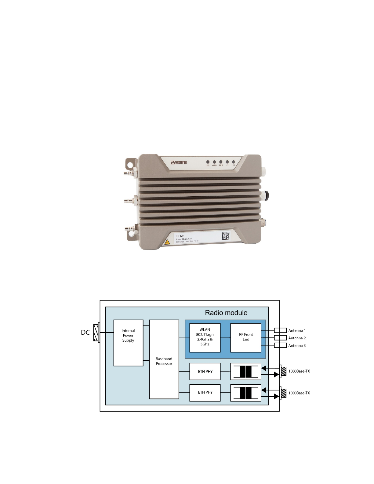
Figure 1 RT-320 Picture
The product functional block diagram is shown in Figure 2.
Figure 2 RT-310 / RT-320 Block diagram
Page 7

RT-310 / RT-320 User Guide
Page 7 (30)
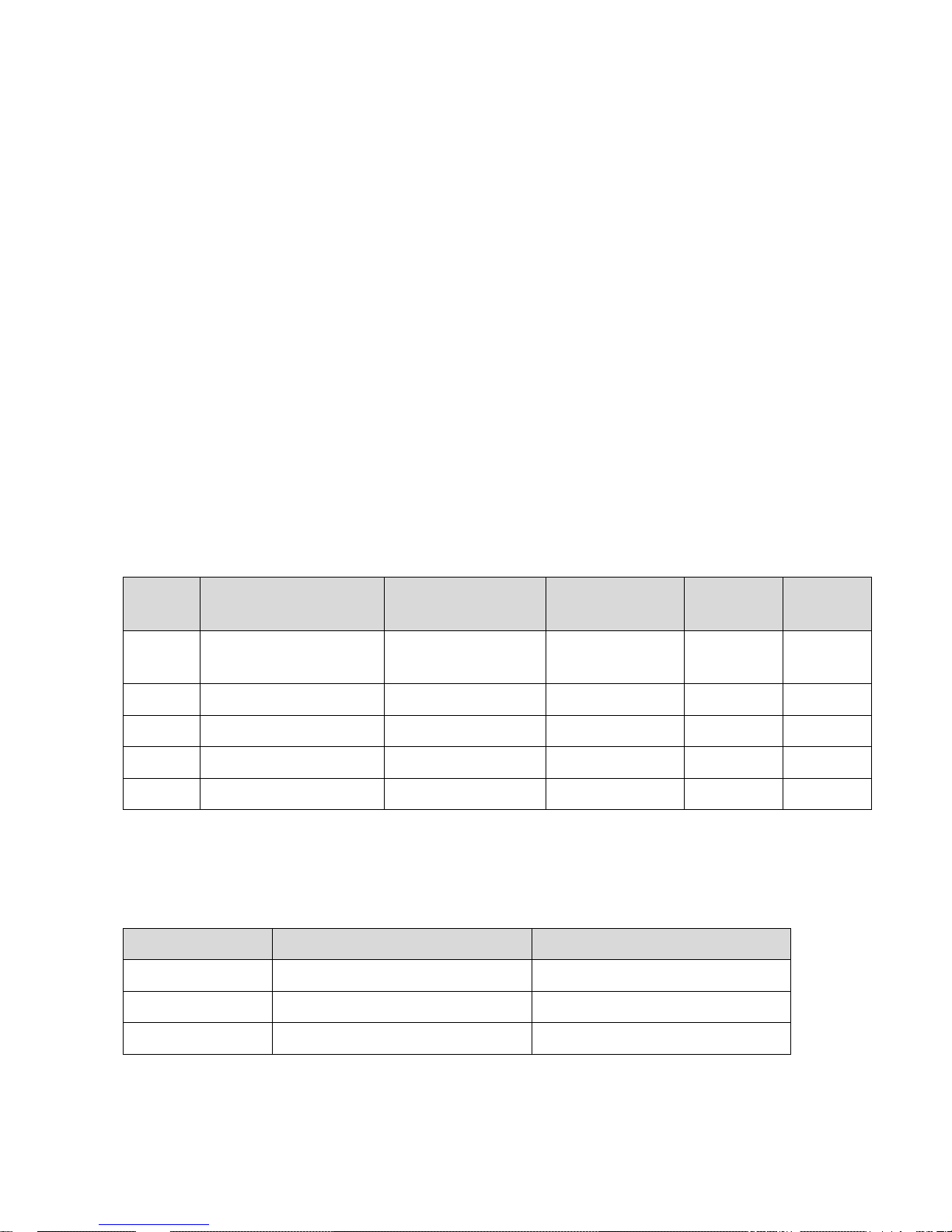
2.1 Supported Product Versions, Variants and SW
Supported product versions, variants and SW:
Specification Value Notes
Product Versions/ Variants RT-320
RT-310
Limited operating modes and output
power in comparison to RT-320,
please refer to product datasheet for
more details
Software Version V6.8 and higher
Table 2 Supported product versions, variants and SW
Page 8
RT-310 / RT-320 User Guide
Page 8 (30)
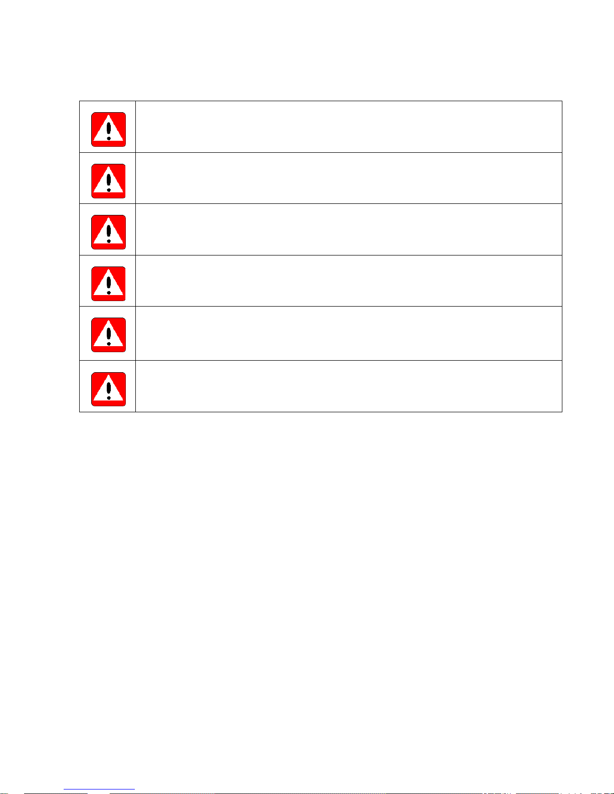
2.2 Important Safet y Notes
Danger!
Do not use damaged equipment and/or accessories such as damaged power cord.
Danger!
Never try to open the device. There are no serviceable parts inside.
Warning!
Product warranty gets void and any liability will be disclaimed when opening the device.
Warning!
Read this user guide carefully before mounting, installing and operating the device.
Warning!
Never unplug equipment from the electrical outlet by holding the cord only, always disc onnec t the
cable by applying force directly to the plug.
Warning!
Do not operate the device in any other environmental conditions than it is designed for.
Table 3 Important safety notes
Page 9

RT-310 / RT-320 User Guide
Page 9 (30)
2.3 RT-320 Delivery Content
The RT-320 delivery consists of following main components:
Description Number of Parts Notes
RT-320 1
Connector Dust Cap 6
Temporary protection of connectors:
• 2 plastic protection caps for Ethernet connectors
• 1 plastic protection cap for power connector
• 3 plastic protection caps for antenna connectors
Table 4 RT-320 delivery content
2.4 RT-310 Delivery Content
The RT-310 delivery consists of following main components:
Description Number of Parts Notes
RT-310 1
Connector Dust Cap 6
Temporary protection of connectors:
• 2 plastic protection caps for Ethernet connectors
• 1 plastic protection cap for power connector
• 3 plastic protection caps for antenna connectors
Table 5 RT-310 delivery content
Page 10

RT-310 / RT-320 User Guide
Page 10 (30)
2.5 Installation Countries
Installation country regulatory limits and operating parameters are controlled by Software Country Code
parameter. This product supports:
Country Code Operating Frequency Ranges Notes
Europe (EU) 2412 … 2472 MHz and
5180 … 5320 MHz,
5500 … 5700 MHz
Operation according to ETSI limitations
For detailed specification, refer to document [1]
United States
(USA)
2412 … 2472 MHz and
5180 … 5320 MHz,
5500 … 5700 MHz
5725 … 5850 MHz
Operation according to FCC limitations
For detailed specification, refer document [1]
Canada (CANADA) 2412 … 2472 MHz and
5180 … 5320 MHz,
5500 … 5700 MHz
5725 … 5850 MHz
Operation according to IC limitations
For detailed specification, refer to document [1]
Table 6 Installation countries
Note: Further Software releases might support additional country codes, for up-to-date country code specification
refer to document [1]
2.6 Regulatory Notices
Caution!
Any changes or modifications shall be approved by the party responsible for compliance. If not, users could void
the user's authority to operate the equipment.
Country code and antenna gain needs to be set properly for correct functionality in the installed country.
2.6.1 United States (FCC)
The enclosed device complies with Part 15 of the FCC Rules. Operation is subject to the following two conditions:
(i.) this device may not cause harmful interference and (ii.) this device must accept any interference received,
including interference that may cause undesired operation.
Contains FCC ID: 2AEJD-103902-DT50RF
RF Exposure requirements:
To satisfy FCC RF exposure requirements for mobile transmitting devices, a separation distance of 20 cm or more
should be maintained between the antenna of this device and persons during operation. To ensure compliance,
operations at closer distances than this are not recommended.
Antennas:
The device can operate with the antennas listed in 2.6.3.
Page 11
RT-310 / RT-320 User Guide
Page 11 (30)
2.6.2 Canada (IC)
This device complies with Industry Canada’s license-exempt RSSs. Operation is subject to the following two
conditions:
1. This device may not cause interference.
2. This device must accept any interference, including interference that may cause undesired operation of
the device.
Le présent appareil est conforme aux CNR d’Industrie Canada applicables aux appareils radio exempts de
licence. L’exploitation est autorisée aux deux conditions suivantes:
1. l’appareil ne doit pas produire de brouillage.
2. l’utilisateur de l’appareil doit accepter tout brouillage radioélectrique subi, même si le brouillage est
susceptible d’en compromettre le fonctionnement.
IC Certification Number of the implemented WLAN communication module: 9301A-103902DT50
Antennas:
The device can operate with the antennas listed in 2.6.3.
2.6.3 Certified Antennas for FCC and IC
The following antennas can be used with the device (the antenna type ID has to be set to the right value):
Type Part number Manufacturer Gain Chains Antenna
Type ID
Dipole F51-N Tekfun 2 GHz: 4.5 dBi max
5 GHz: 7 dBi max
1, 2, 3 04
Patch SPA 2400/75/8/0/V Huber & Suhner 2 GHz: 7.5 dBi max 1, 2, 3 05
Patch SPA-5600/40/14/0/V_2 Huber & Suhner 5 GHz: 14 dBi max 1, 2 06
Patch SPA-5600/65/9/0/MIMO Huber & Suhner 5 GHz: 9 dBi max 1, 2, 3 07
Shark SPA-5600/45/12/10/V Huber & Suhner 5 GHz: 12 dBi max 1, 2 08
Table 7: FCC and IC certified antennas
2.7 Output power limitations
The RT-310 and RT-320 have following output power limitations for ambient temperatures from -40°C to +70°C.
Active antennas Max. output power with DC supply Max. output power with PoE supply
1 22 dBm per chain 22 dBm per chain
2 22 dBm per chain 22 dBm per chain
3 22 dBm per chain 20 dBm per chain
Table 8: Output power limitations
Page 12
RT-310 / RT-320 User Guide
Page 12 (30)
2.8 Product Identification and Version Information
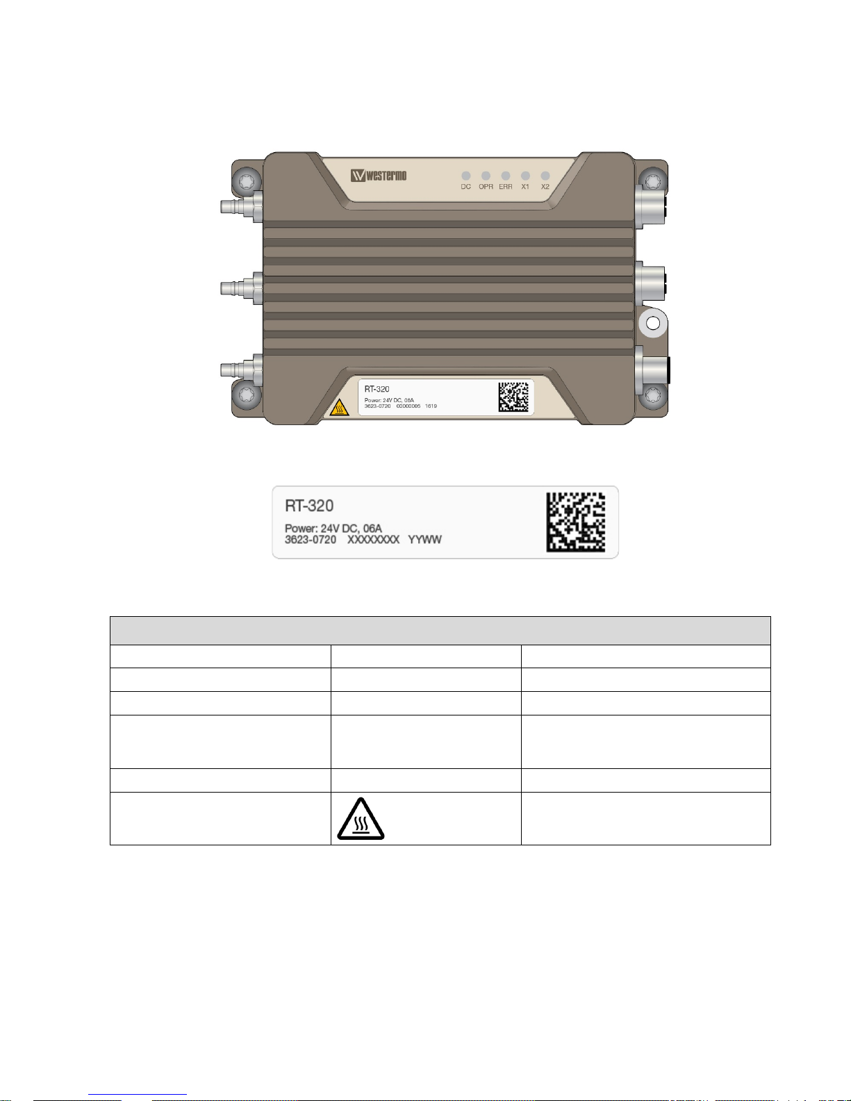
Product identification infor mation is available at the product label. The produc t label is fixed to the device.
Figure 3 RT-320 Product identification label position
Figure 4 RT-320 Product identification label example
Specification Value Notes
Product Name RT-320
Or respectively RT-310
Part Number 3623-0720
Or respectively 3623-0710
SN XXXXXXXX
Internal serial number
Manufacturing Date YYWW
The date format is:
YY = manufacturing year
WW = manufacturing week
BAR CODE SN information
Data matrix
Hot surfaces
Surface temperature can be above 60°C
Table 9 Product Identification Label
Page 13
RT-310 / RT-320 User Guide
Page 13 (30)
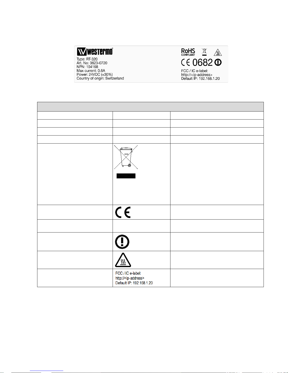
At the rear side of the product further product specific information is printed to a second label.
Figure 5 RT-320 Product label example
Specification Value Notes
Product Name RT-320
Or respectively RT-310
Part Number 3623-0720
Or respectively 3623-0710
Max current 0.6 A
Information on input current
Power
Information on input power feed
WEEE
This symbol, found on the product indicates
that this product should not be treated as
household waste when disposing of it.
Instead it must be handled over to an
applicable collection point for the recycling of
electrical and electronic equipment.
By ensuring this product is disposed correctly,
you will help prevent potential negative
consequences to the environment and human
health, which could be otherwise be caused
by inappropriate disposal of this product.
CE
CE mark
Notified body 0682
Identification number of the notified body
Cetecom ICT Services GmbH Germany
R&TTE directive
Class 2 radio equipment for which restrictions
apply to putting into service.
Hot surfaces
Surface temperature can be above 60°C.
FCC / IC e-label
Link to the FCC / IC e-label
Table 10 Product label
Page 14

RT-310 / RT-320 User Guide
Page 14 (30)
3 Technical Features
Technical features are described in reference documents [2] and [3].
4 Installation
4.1 Installatio n Procedure, Overview
Order of Installation Step Description
1. Fixing The product is fixed in operating environment, ensuring that the environment
complies with the installation environment constrains. See chapter 4.2
2. System Grounding The system grounding is ensured and verified based on customer installation.
See chapter 4.4
3. Antennas The antenna interfaces are installed based on customer requirements. See
chapter 4.5
4. Ethernet The Ethernet data interfaces are installed. See chapter 4.6
5. Power Feed Power feed cable is connected (the power may be already activated in the cable),
the power supply is switched on and verify that the LED indicators shows correct
power up procedure. See chapter 4.7
6. Configuration The configuration process is described in reference document [1] chapter:
Configuration.
Table 11 Installation procedure
Page 15
RT-310 / RT-320 User Guide
Page 15 (30)
4.2 Dimensions for Fixing Poi nt s
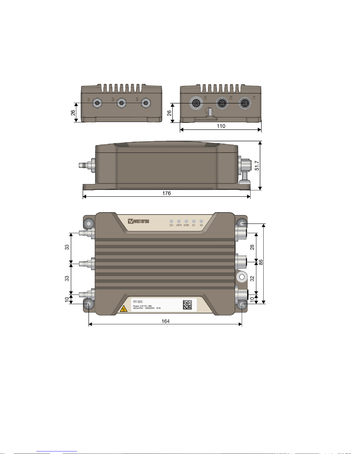
4.2.1 Mechanical Overview
Figure 6 Mechanical overview
Page 16

RT-310 / RT-320 User Guide
Page 16 (30)
Parameter Value Notes
Maximum dimensions
176 x 110 x 52 mm Length with antenna connectors
180mm
Maximum dimensions, with cables
but not including antennas
App 300 x 110 x 52 mm Space needed for installation
Location of the fixing points
In each corner With four M6 screws
Color
RAL 7006, beige grey Powder Coating
Protection
IP66
Weight
1.08 kg
Table 12 Dimensions and weight
Page 17
RT-310 / RT-320 User Guide
Page 17 (30)
4.2.2 Mechanical Integration, Fixing Points and Connector Positions
The product must be fixed with the four fixing points located at the corners of the product. M6 screws shall be
used for the fixation of the product. The screws shall be tightened with min. 3.0 Nm (fixing screw ISO 898/1,
quality class 8.8).
NOTICE: All four specified fixing points must be used for fixing. The fixing surface should be flat to have all fixing
points connected to the surface.
The product has a membrane vent at the connector side of the product for equalizing pressure changes.
NOTICE: The vent does not require any maintenance. Any manipulations at the vent are not allowed.
Specification Value
Fixing holes
positions
Fixing holes without threads, for 6mm screws: four pieces of slot holes, see: Figure 6
0 mm, 0 mm 164 mm, 0 mm
0 mm, 86 mm 164 mm, 86 mm
Connector
positions
DC POWER Antenna 1 Antenna 2 Antenna 3 1000Base-TX
ETH1
1000Base-TX
ETH2
See
Figure 7
Figure 14
See
Figure 7
Figure 12
See
Figure 7
Figure 12
See
Figure 7
Figure 12
See
Figure 7
Figure 13
See
Figure 7
Figure 13
Grounding See Figure 7, Figure 11
Table 13 Fixing points and connector positions
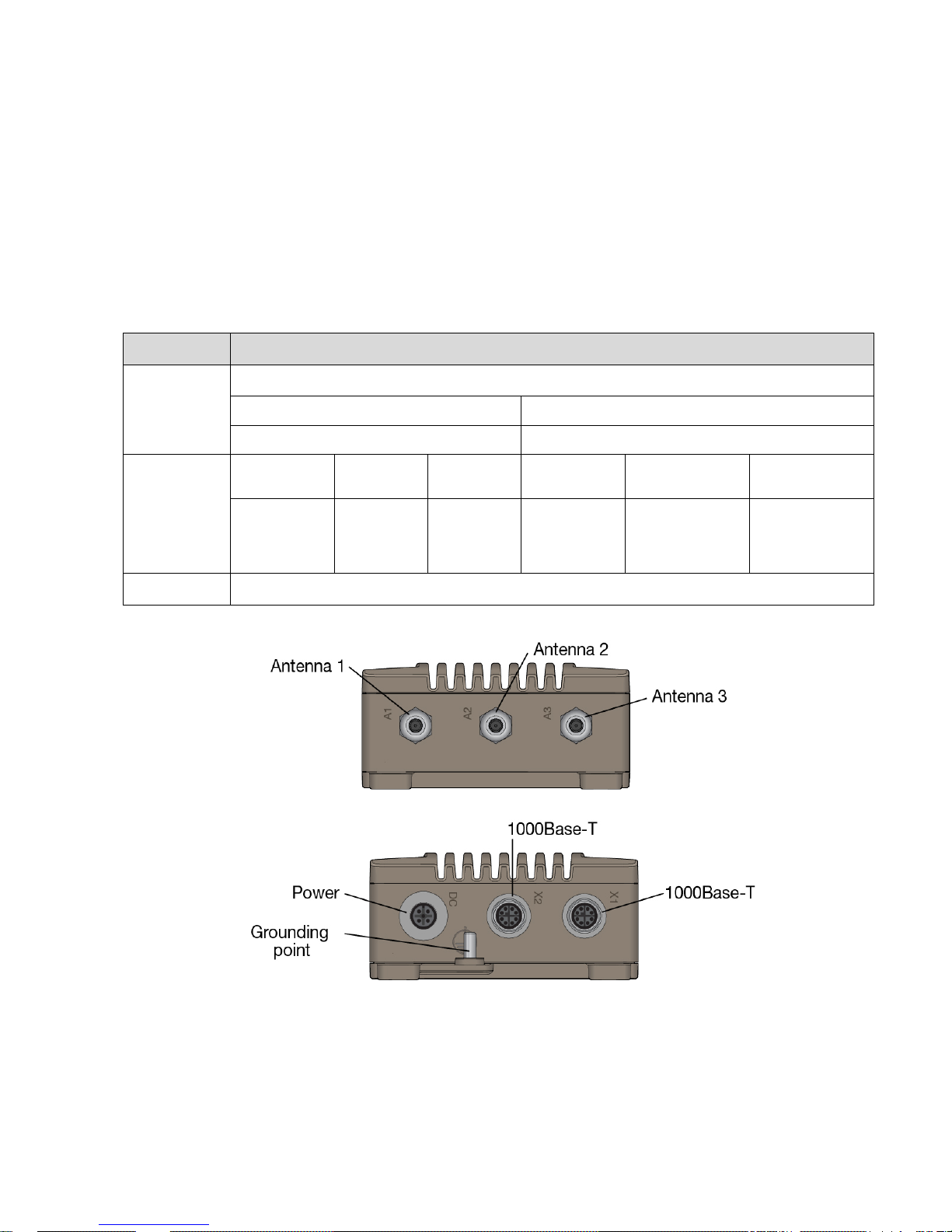
Figure 7 Connectors
Page 18

RT-310 / RT-320 User Guide
Page 18 (30)
4.3 Considerations When Mounting the Device
4.3.1 General Installation Considerations
When planning an installation at least the following points shall be considered:
• Indoor: protecting for dust (to ensure heat dissipation), vandalism, animals (rats, birds etc)
• Outdoor: protecting for sun (to optimize ambient temperature range), dust, dirt, vandalism etc.
4.3.2 Temperature Alarms
This product has integrated temperature sensors for monitoring the internal device temperature. The limits for the
sensors are set so, that operation without alarm is ensured for ambient temperatures as specified for the product
assuming correct installation.
NOTICE: The limits have been set so that some of the components are close to the limit of the specified
temperature range. For this reason the unit shall not be operated in conditions where the temperature alarm is
activated.
4.3.3 Ambient Operating Temperature Range
This product includes a vent allowing controlled air exchange due to temperature changes. Humidity is blocked by
the vent.
To ensure correct operation over the whole specified temperature range, certain aspects need to be considered.
The limits are defined for installations with free air flow in the installation environment.
It shall be noted that in real environment:
• Limited air flow is rising the device temperature and may lower the upper limit of the operating temperature
range
• Conducted heat exchange through metal surfaces at the product fixing point is improving the device heat
transfer and improving the operating conditions
• Temperature is dependent on the operational parameters, like RF output power, amount of traffic
• This product has internal temperature sensors that will issue alarms for too high or too low temperature. The
operating conditions shall be ensured so that the normal operation does not cause temperature alarms. Any
temperature alarms shall be immediately rectified. See reference document [1] for detailed specification of the
temperature sensors alarms.
Page 19
RT-310 / RT-320 User Guide
Page 19 (30)
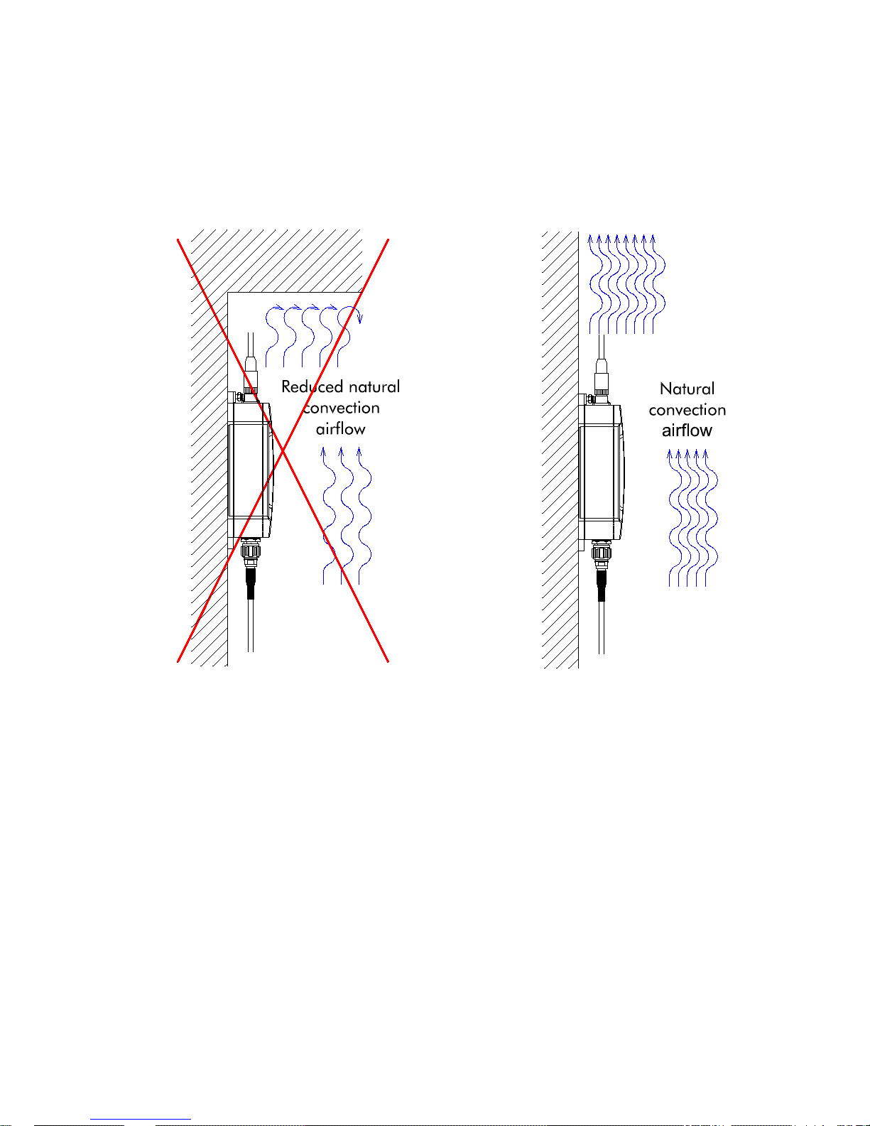
4.3.4 Installations at Very High Temperatures
For installations, where the product is operated close to its maximum specified ambient temperature (+55°C
<TAmbient < +70°C), it must be ensured that the natural convection is not blocked by objects close to the product.
Figure 8 Installation with blocked airflow shall be
avoided
Figure 9 Installation with free airflow - good
installation
Page 20
RT-310 / RT-320 User Guide
Page 20 (30)
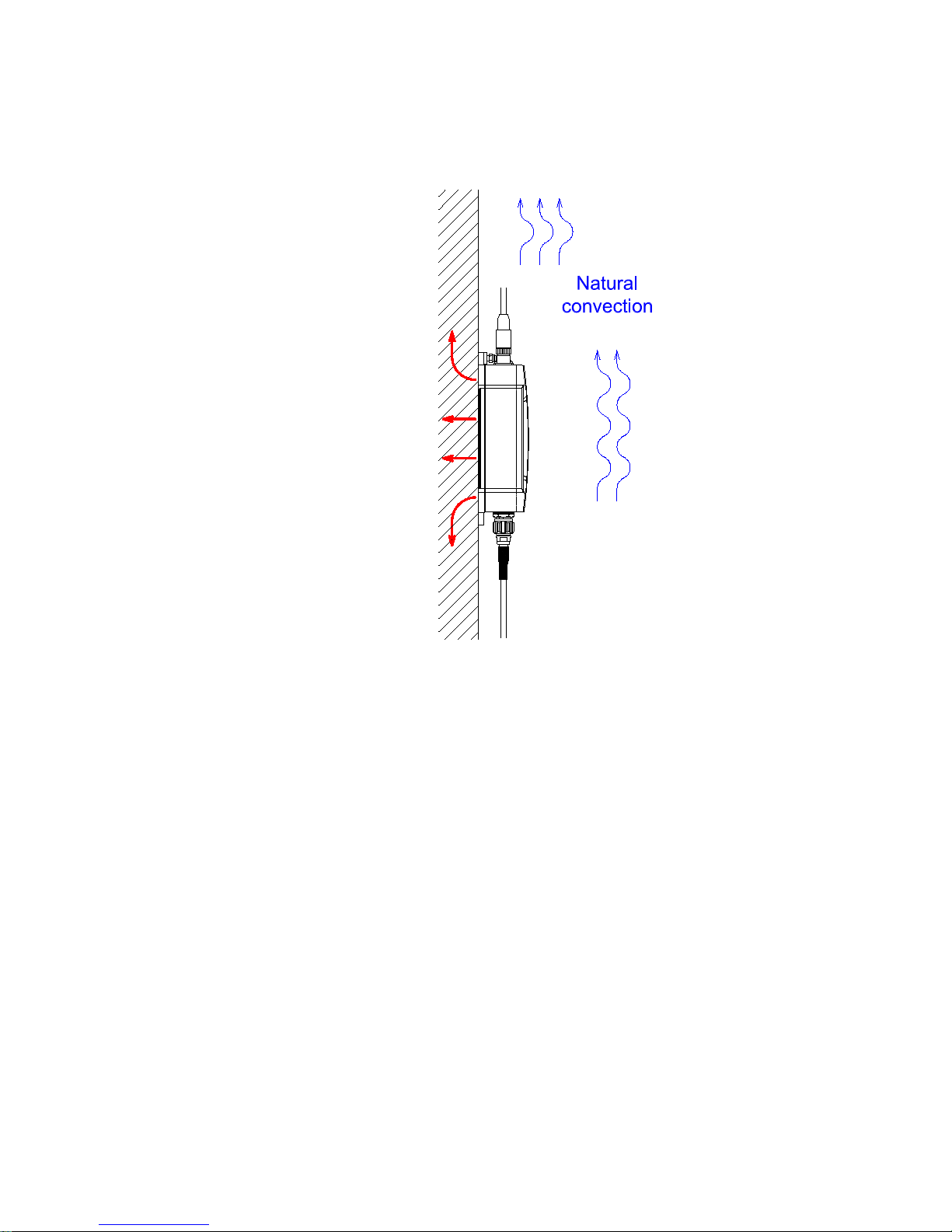
When operating the device at ambient temperatures above app. +60C it is recommended to mount the device to a
metallic base plate t o improve the heat dissipation. The base plate increases the surface to spread the heat.
Figure 10 Improved heat transfer based on fixing plate
Page 21
RT-310 / RT-320 User Guide
Page 21 (30)
4.4 Connecting the System Grounding
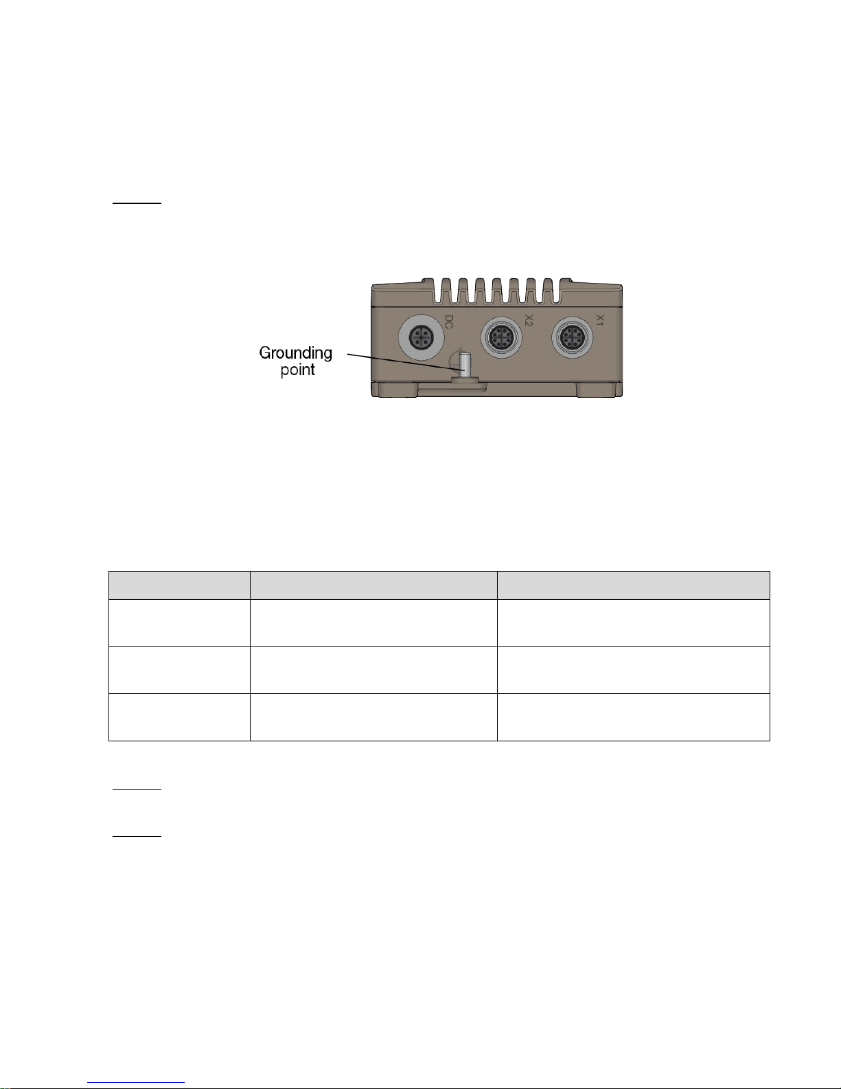
There is a single grounding connect ion po int in RT-310/ RT-320. An M5 grounding screw at the housing is used
for grounding (see Figure 11).
NOTICE: The grounding is organized by connecting the grounding to the ground contact in the casing. For the
grounding at the ground contact (M5 stud), a short wire with a cross section of at least 6.0 mm
2
shall be used.
The grounding wire is set below the rip-lock washer. The nut is fixed for good reliable grounding contact. The
tightening torque of the nut shall be 2.0 Nm.
Figure 11 Grounding contact
4.5 Connecting the RF Antenna Int e rf ace s
4.5.1 RF Antenna Interface Operation Modes
RT-310/RT-320 has three antenna interfaces. The antenna interfaces are operating independently of each other.
Antenna Function Operation Notes
A1 Antenna 1 is used for both transmitting
and receiving
The antenna A1 shall be used.
A2 Antenna 2 is used for both transmitting
and receiving
The antenna A2 can be enabled or disabled.
A3 Antenna 3 is used for both transmitting
and receiving
The antenna A3 can be enabled or disabled.
Table 14 RF Antenna interface operation
NOTICE: If antenna A2 and/or A3 will be NOT used in the customer application, the antenna connector MUST be
terminated with a 50 ohm termination.
NOTICE: The antenna interfaces are protected against lightning with special protection devices. To ensure correct
operation of these devices it is important, that the earth grounding contact is connected to protective earth as
described in chapter
4.4.
Page 22
RT-310 / RT-320 User Guide
Page 22 (30)
4.5.2 RF Antenna Connectors
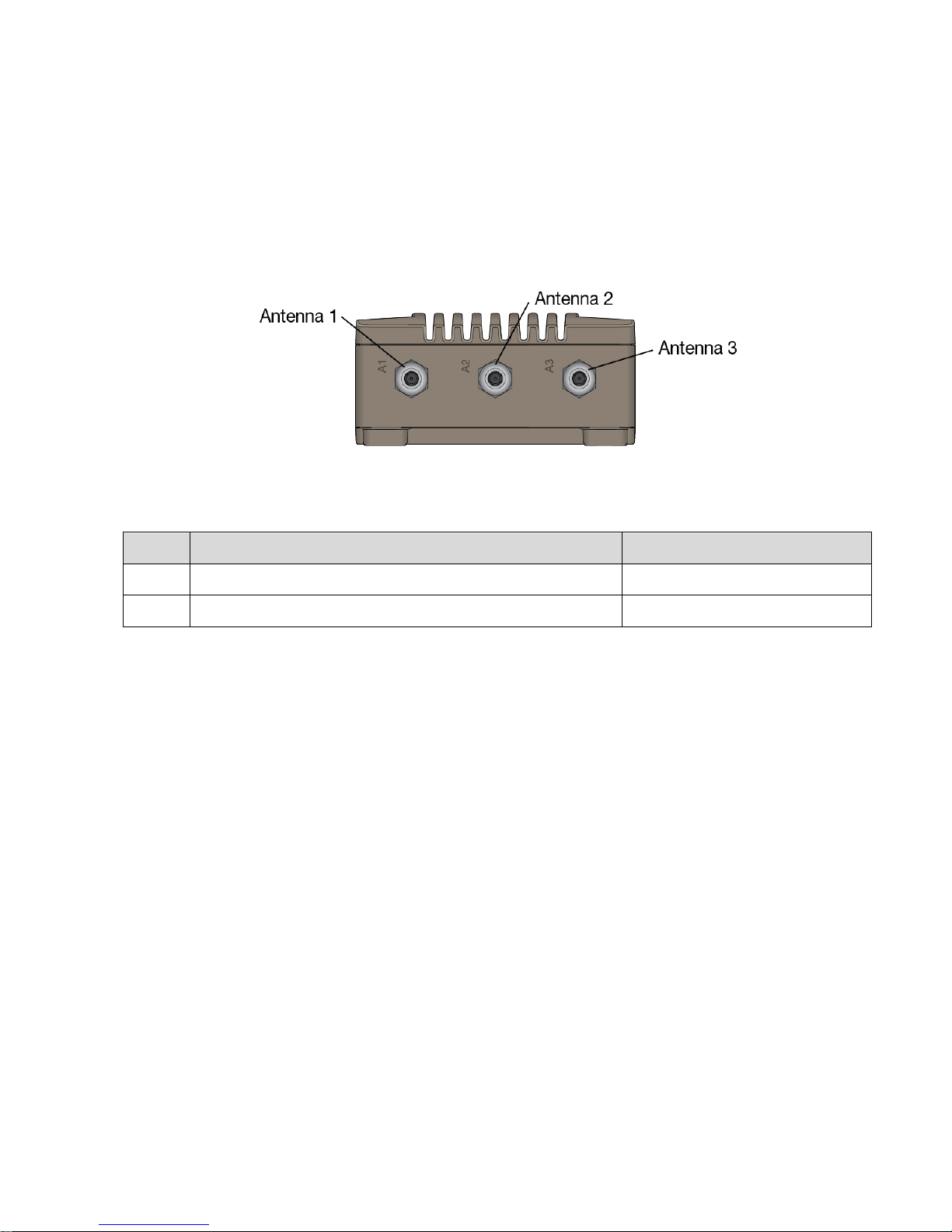
The antenna connectors are identified with the text markings A1 (Antenna 1), A2 (Antenna 2) and A3 (Antenna 3)
in the mechanics.
The antennas might be fixed in antenna connectors directly or using antenna cables fixed to the antenna
connectors.
Figure 12 Antenna interfaces
NOTICE: If one of the antennas is NOT used, the unused antenna connectors MUST be terminated with 50 ohm
termination.
Pin Signal Name, Function Notes
1 Center pin: RF signal Connector Type: QMA – Female
2 Connector body: RF ground
Table 15 Pinning: RF antenna connector
Page 23
RT-310 / RT-320 User Guide
Page 23 (30)
4.6 Connecting Ethernet Inter f a c e
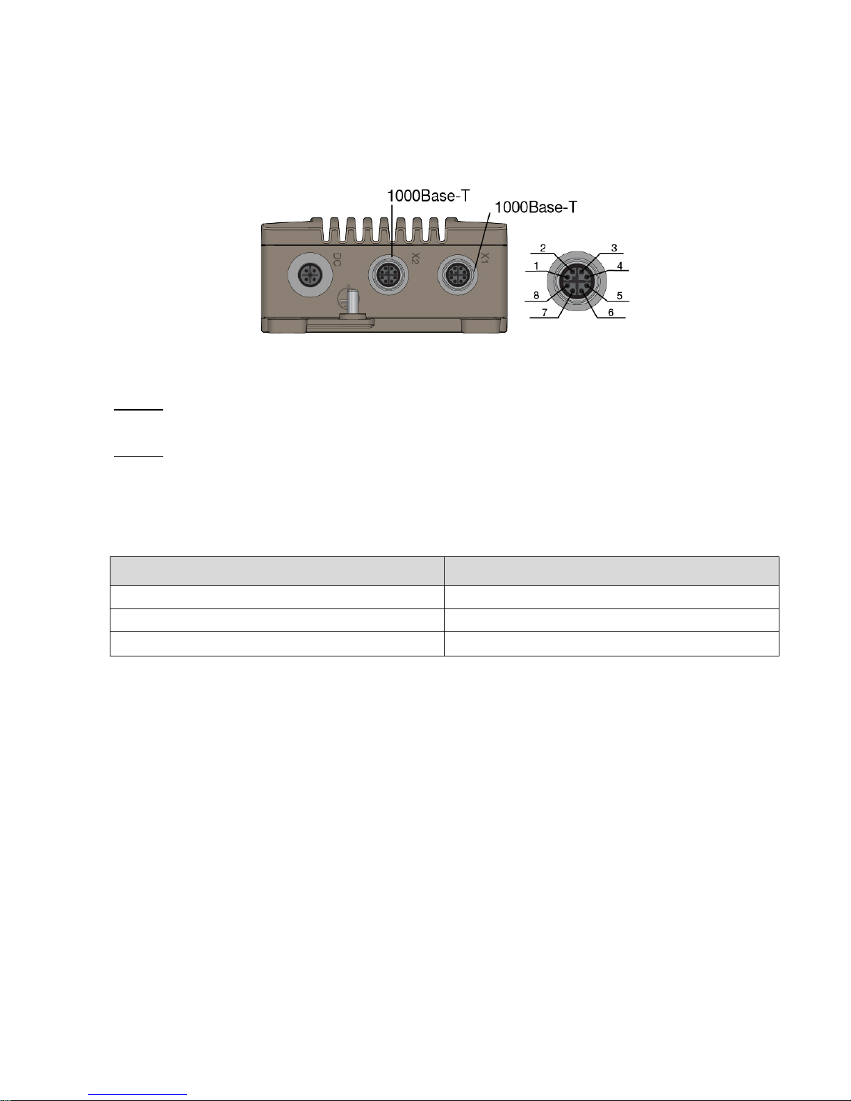
RT-310/RT-320 has two Ethernet interfac es. M12 industrial standard connector with keying is used. The Ethernet
connectors are identified with the text markings ETH1 (Ethernet 1) and ETH2 (Ethernet 2) in the mechanics.
Figure 13 Ethernet interfaces
The connectors should be assembled with correct torque (appr. 1.0 Nm, check connector manufacturer data)
NOTICE: Ethernet signals have a trans f ormer in the signal lines. There is no addition al l ine prot ec ti on f or Light ning
etc included at product hardware module.
NOTICE: The Ethernet Interface connector fulfills the IP66 protection when the cable plug or the dust cap is
connected. If the Ethernet function is not used in application, the protective dust cap must be closed.
4.6.1 Ethernet Port Features
The Ethernet port supports the following network standards:
Network Standard Description
10BASE-T Ethernet over two pairs of twisted wires
100BASE-TX Fast Ethernet over two pairs of twisted wires
1000BASE-TX Gigabit Ethernet ov er four pairs of twisted wires
Table 16 4.6.1 Ethernet port features
The Ethernet ports suppor t auto-negotiated 10 Mbps / 1 00 Mbps / 1000 Mbps operat ion. Automatic MDI/MDIX
crossover is supporte d for 10BASE-T, 100BASE-T, 1000BASE-T operation. F or final installation the use of autonegotiation is however not recommended.
Page 24
RT-310 / RT-320 User Guide
Page 24 (30)
4.6.2 Ethernet Connector
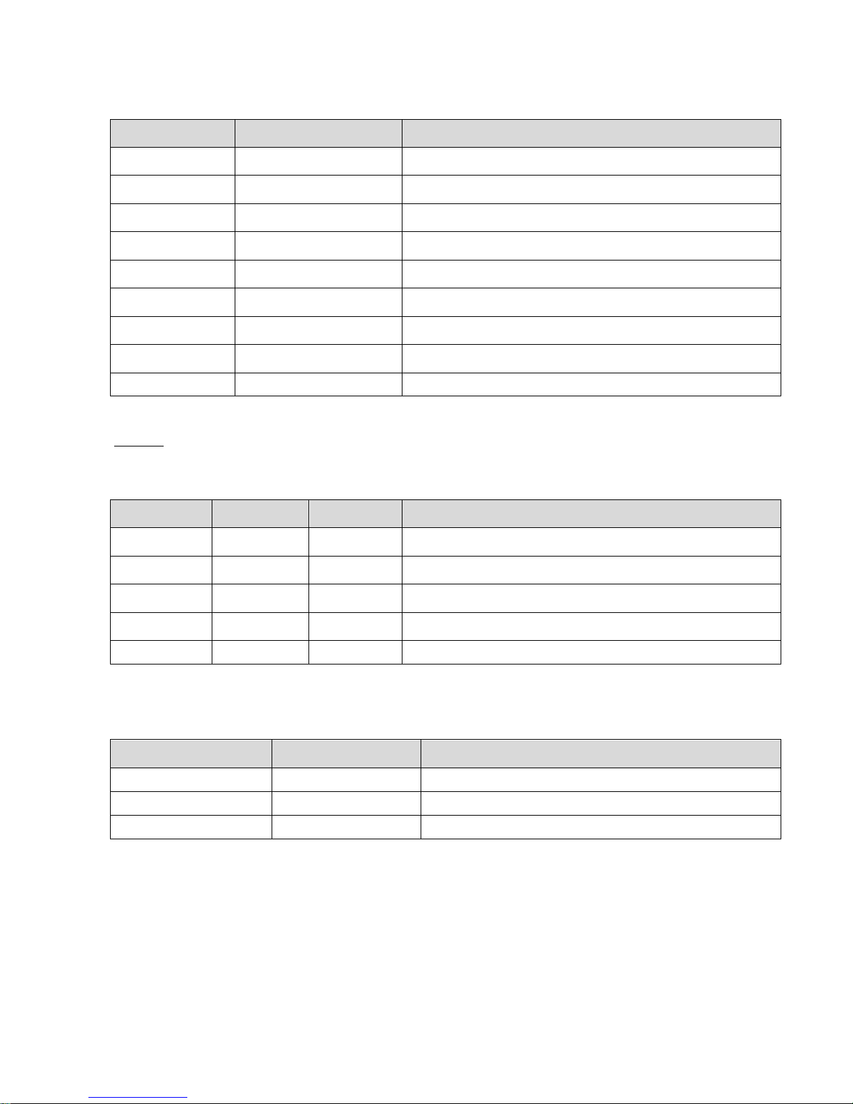
Connector Pin Signal name, Function Notes
1
MX1 +
Connector Type: Industrial ETHERNET M12-Socket “X”-coded
2
MX1 -
3
MX2 +
4
MX2 -
5
MX4 +
6
MX4 -
7
MX3 -
8
MX3 +
Housing Ground For possible cable protection/screening
Table 17 Ethernet connector
NOTICE: The pinning is compliant to IONA, Industrial Ethernet Planning and Installation Guide, Release 4.0.
4.6.3 PoE Connection (ETH2 only)
Connector Pin 1000 mode A 1000 mode B Notes
1, 2
DC+
Connector Type: Industrial ETHERNET M12-Socket “X”-coded
3, 4
DC-
5, 6
DC-
7, 8
DC+
Housing Ground Ground For possible cable protection/screening
Table 18 PoE connection
4.6.4 PoE Power Feed Specifications
Parameter Value Notes
Nominal Voltage 48 VDC
Voltage Range 37 VDC … 57 VDC
Power classification Class 3
Table 19 PoE power feed specifications
Page 25
RT-310 / RT-320 User Guide
Page 25 (30)
4.7 Connecting the Power Feed
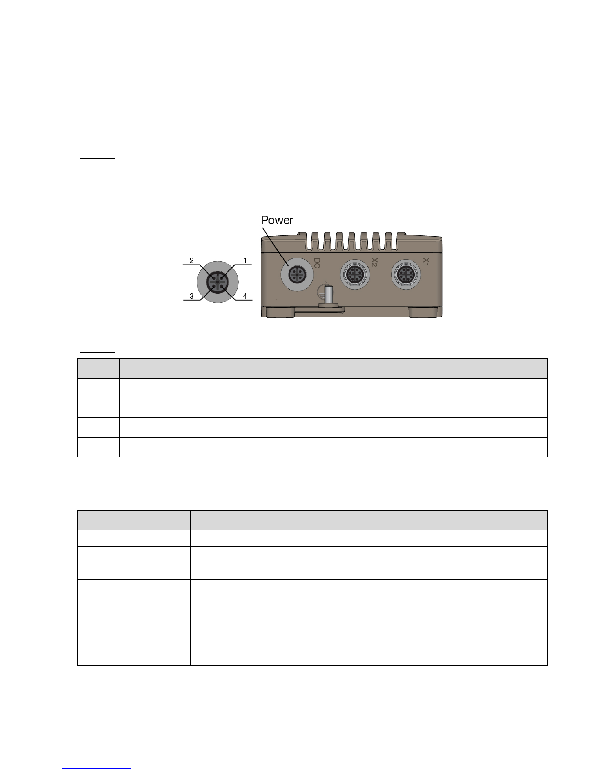
The power feed is connected to the POWER connector. The power supply interface is a galvanically isolated
interface; it is protected against surge and ESD. The power connector is keyed ensuring correct connector
position.
NOTICE: The Power Feed Cable is not part of delivery.
4.7.1 Power Feed Connector
Connector type: M12 A-coded 4-pin male connector according to IEC 61076-2-101.
Figure 14 RT-310/RT-320, power connector
NOTICE: Power connector pinning: clockwise 1, 4, 3, 2 starting from the coding mark.
Pin Signal Name, Function Notes
1
+VCC1 or -COM The supply voltage is applied, polarity free
2
Not used
3
-COM or +VCC2 The supply voltage is applied, polarity free
4
Not used
Table 20 Pinning: PWR connector
4.7.2 Power Feed Specifications
Parameter Value Notes
Nominal Voltage 24 VDC
Voltage Range 16.8 VDC to 33.6 VDC
Nominal current 0.6 A Guaranteed min/max operating voltage range
Power consumption App. 4 W
App. 9 W
Idle load
Full load
Selecting external
power connector and
power cable diameter Allowed wire cross
section
Min. 0.5 mm2 Cable Plug:
e.g. Phoenix Contact, SACC-M12FS-4CON-PG7-M
Table 21 Power feed specifications
Page 26
RT-310 / RT-320 User Guide
Page 26 (30)
4.7.3 Power Consumption Examples
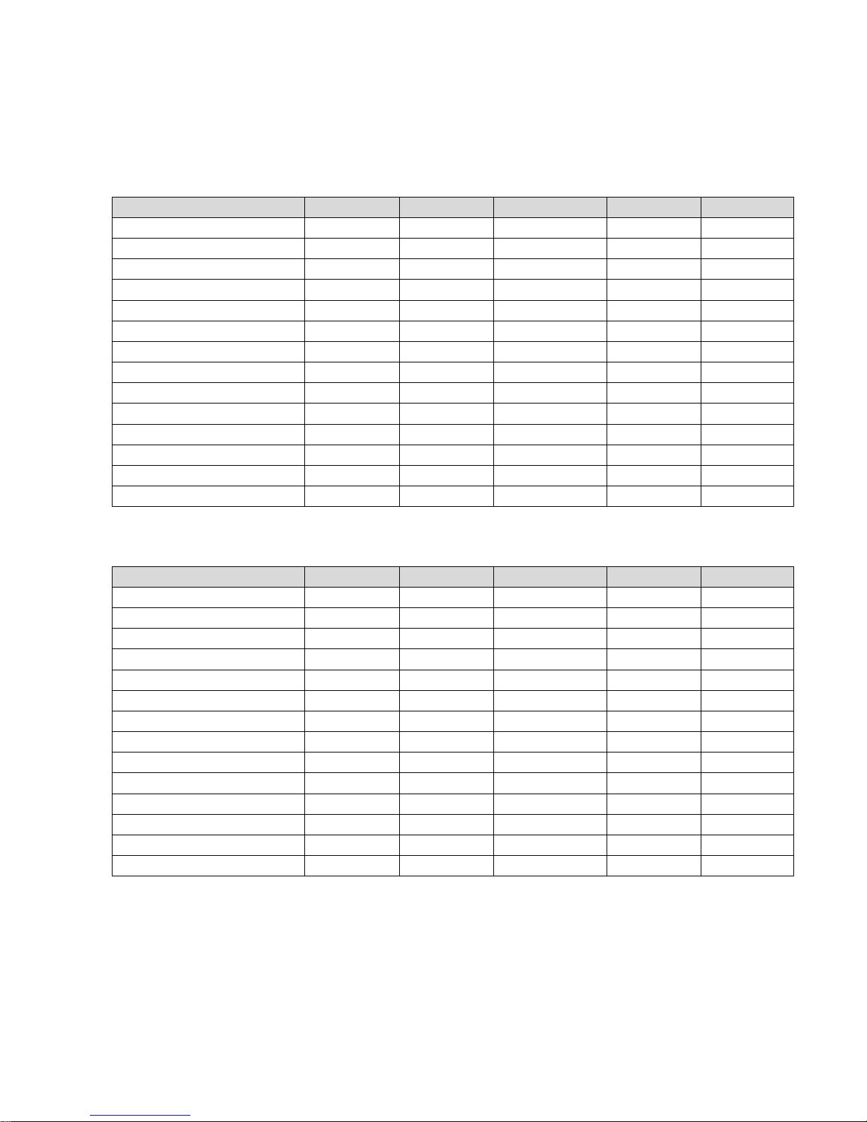
The power consumption is dependent on the operational parameters, like RF output power, amount of routed
traffic and the RX duty cycle.
Test case
Antennas
TX duty cycle
TX output
Amb. Temp.
Avg. Power
2.4 GHz idle
1x1, 2x2, 3x3
2%
1…3 x 22 dBm
-40°C
P = 3.80 W
2.4 GHz idle
1x1, 2x2, 3x3
2%
1…3 x 22 dBm
+70°C
P = 4.41 W
2.4 GHz TX50 SISO, -40
1x1
50%
1 x 22 dBm
-40°C
P = 4.53 W
2.4 GHz TX50 SISO +70
1x1
50%
1 x 22 dBm
+70°C
P = 5.09 W
2.4 GHz TX50 2x2 MIMO -40
2x2
50%
2 x 22 dBm
-40°C
P = 5.28 W
2.4 GHz TX50 2x2 MIMO +70
2x2
50%
2 x 22 dBm
+70°C
P = 5.96 W
2.4 GHz TX50 3x3 MIMO -40
3x3
50%
3 x 22 dBm
-40°C
P = 6.03 W
2.4 GHz TX50 3x3 MIMO +70
3x3
50%
3 x 22 dBm
+70°C
P = 6.83 W
2.4 GHz TX90 SISO, -40
1x1
90%
1 x 22 dBm
-40°C
P = 5.36 W
2.4 GHz TX90 SISO +70
1x1
90%
1 x 22 dBm
+70°C
P = 5.86 W
2.4 GHz TX90 2x2 MIMO -40
2x2
90%
2 x 22 dBm
-40°C
P = 6.95 W
2.4 GHz TX90 2x2 MIMO +70
2x2
90%
2 x 22 dBm
+70°C
P = 7.46 W
2.4 GHz TX90 3x3 MIMO -40
3x3
90%
3 x 22 dBm
-40°C
P = 8.54 W
2.4 GHz TX90 3x3 MIMO +70
3x3
90%
3 x 22 dBm
+70°C
P = 9.04 W
Table 22: 2.4 GHz power consumption
Test case
Antennas
TX duty cycle
TX output
Amb. Temp.
Avg. Power
2.4 GHz idle
1x1, 2x2, 3x3
2%
1…3 x 22 dBm
-40°C
P = 3.60 W
2.4 GHz idle
1x1, 2x2, 3x3
2%
1…3 x 22 dBm
+70°C
P = 4.27 W
2.4 GHz TX50 SISO, -40
1x1
50%
1 x 21 dBm
-40°C
P = 4.30 W
2.4 GHz TX50 SISO +70
1x1
50%
1 x 21 dBm
+70°C
P = 4.90 W
2.4 GHz TX50 2x2 MIMO -40
2x2
50%
2 x 21 dBm
-40°C
P = 5.05 W
2.4 GHz TX50 2x2 MIMO +70
2x2
50%
2 x 21 dBm
+70°C
P = 5.65 W
2.4 GHz TX50 3x3 MIMO -40
3x3
50%
3 x 21 dBm
-40°C
P = 5.80 W
2.4 GHz TX50 3x3 MIMO +70
3x3
50%
3 x 21 dBm
+70°C
P = 6.40 W
2.4 GHz TX90 SISO, -40
1x1
90%
1 x 21 dBm
-40°C
P = 5.02 W
2.4 GHz TX90 SISO +70
1x1
90%
1 x 21 dBm
+70°C
P = 5.68 W
2.4 GHz TX90 2x2 MIMO -40
2x2
90%
2 x 21 dBm
-40°C
P = 6.41 W
2.4 GHz TX90 2x2 MIMO +70
2x2
90%
2 x 21 dBm
+70°C
P = 7.06 W
2.4 GHz TX90 3x3 MIMO -40
3x3
90%
3 x 21 dBm
-40°C
P = 7.80 W
2.4 GHz TX90 3x3 MIMO +70
3x3
90%
3 x 21 dBm
+70°C
P = 8.44 W
Table 23: 5 GHz power consumption
Page 27
RT-310 / RT-320 User Guide
Page 27 (30)
5 Configuration and Use
The operation parameters in configuration files define the functionality. The complete configuration process is
described in reference document [1].
5.1 LED Indicators During Pow er Up Sequence
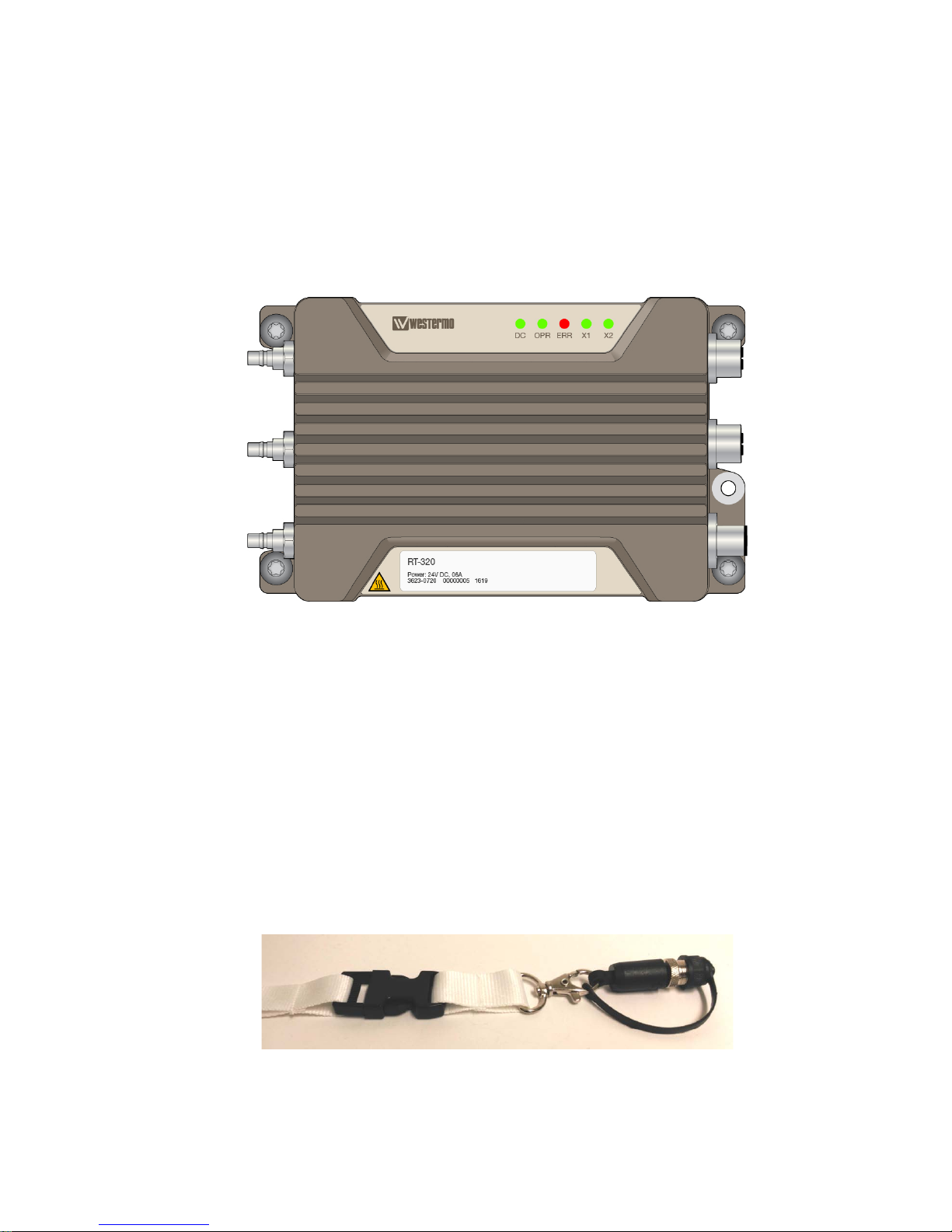
LED behavior during power-up sequence is described in reference document [1] in the chapter Status Indication.
Figure 15 Power, operation, status and Ethernet LEDs
5.2 Factory Reset Interface, Process for Factory Reset
A factory reset is not typically needed for installation. It is required if the device configuration is lost.
The factory reset functionality is included in both Ethernet port interfaces. The factory reset process is performed
using specific factory reset adapter.
5.2.1 Factory Reset Adapter Specification
The factory reset adapter is a special plug for the Ethernet interface that activates the factory reset signal.
There is a specific factory reset adapter available:
FACTORY RESET PLUG X -CODED
Part No.: 3623-0799
Figure 16 Factory reset plug X-coded
Page 28

RT-310 / RT-320 User Guide
Page 28 (30)
5.2.2 Factory Reset Procedure
The Factory Reset is performed with a factory reset adapter that is connected to one of the Ethernet ports during
the start-up.
Step Description
1. Plug the factory reset adapter to one of the Ethernet interfaces.
2. Power the device
3. Wait until factory reset adapter is detected. This is indicated by an ORANGE operation L ED in
combination with a RED status LED
4. Remove factory reset adapter within 15 seconds
5. A successful initiation of a factory Reset is indicated by an ORANGE BLINKING operation LED in
combination with a RED BLINKING failure LED
Table 24 Factory reset procedure
After successful factory reset, the dust cap must be closed to ensure the IP requirements.
Page 29

RT-310 / RT-320 User Guide
Page 29 (30)
6 Maintenance
Danger!
Never open the device. There are no serviceable parts inside!
6.1 Cleaning– Resistance to Chemicals
In case the product is cleaned with cleaning chemicals, the resistance to chemicals of the plastic parts needs to be
respected. The following plastic materials are used in the RT-310/ RT-320:
Ethernet Connector Dust Cap
Polyamide 66 (PA66)
Polyurethane (PUR)
Pressure Equalizer Vent
Polyamide 6 (PA6)
Polytetrafluoroethylene (PTFE)
Stickers
Autotex XE
Page 30

RT-310 / RT-320 User Guide
Page 30 (30)
6.2 Troubleshooting Based on Func t ional Behavior
Please read the troubleshooting instructions in reference document [1].
6.3 Repair Work
This product is exchanged as a whole unit. On product level no repair work is done in the field. Broken units need
to be returned to the supplier for repair.
6.3.1 Exchange of the Product
Order of Installation Step Description
1. Remove Cables
Remove cables in the following order:
• Power cable
• Antenna cable A1
• Antenna cable A2
• Antenna cable A3
• Ethernet cables
• Protective earth cable
2. Open Screw
The four M6 screws in each corner of the product must be opened
and removed completely
3. Exchange
Lift the product out of its position. Place a replacement unit to its
position
4. Fix Screws
The four M6 screws in each corner must be fixed again.
5. Connect Cables
Connect cables in the following order:
• Protective earth cable
• Antenna cable A1
• Antenna cable A2
• Antenna cable A3
• Ethernet cables
• Power cable
6. Configure
Download configuration to the product
Table 25 Exchange flow
 Loading...