

Page 1

User Guide
6641-2223
RedFox
RAIL
Westermo Teleindustri AB
©
Ethernet switch and router
approved for railway usage
www.westermo.com
Page 2

Software tools
Related software tools are available in the folder software tools under
technical support on the Westermo website.
License Information
This device contains public available software which is under the GPL lincense.
For more information see legal.pdf included with all firmware releases.
This product includes software developed by the OpenSSL Project for use in the
OpenSSL Toolkit, http://www.openssl.org
Legal information
The contents of this document are provided “as is”. Except as required by applicable
law, no warranties of any kind, either express or implied, including, but not limited to,
the implied warranties of merchantability and fitness for a particular purpose, are made
in relation to the accuracy and reliability or contents of this document. Westermo
reserves the right to revise this document or withdraw it at any time without prior
notice.
Under no circumstances shall Westermo be responsible for any loss of data or income
or any special, incidental, and consequential or indirect damages howsoever caused.
More information about Westermo can be found at the following Internet address:
http://www.westermo.com
2
6641-2223
Page 3

Safety
!
!
Before installation:
Read this manual completely and gather all information on the unit. Make sure that
you understand it fully. Check that your application does not exceed the safe operating specifications for this unit.
This unit should only be installed by qualified personnel.
This unit should be built-in to an apparatus cabinet, or similar, where access is
restricted to service personnel only. The power supply wiring must be sufficiently
fused, recom mended fuse: 4 A slow. It must be possible to manually disconnect
powe r.
Ensure compliance to national installation regulations.
This unit relies on convection heating. Make sure that it is installed so that the
ambient temperature is within the specified temperature range, e.g. by avoiding
obstruction of the airflow around the unit.
Before mounting, using or removing this unit:
Prevent access to hazardous voltage by disconnecting the unit from all power supply.
WARNING
Do not open connected unit. Hazardous voltage may occur within this unit when
connected to power supply.
Before powering-up, a protective earthing conductor must be connected to the
protective earthing terminal and have a cross-sectional area of at least 1.5 mm².
When this unit is operated at an ambient temperature above +55°C (+131°F),
+55°C (+131°F), the External Surface of Equipment may exceed Touch
Temperature Limit according to EN/IEC/UL 60950-1.
To reduce the risk of fire, use only No. 26 AWG or larger telecommunication line
cord.
Care recommendations
Follow the care recommendations below to maintain full operation of unit and to fulfill
the warranty obligations.
This unit must not be operating with removed covers or lids.
Do not attempt to disassemble the unit. There are not any user serviceable parts inside.
Do not drop, knock or shake the unit. Rough handling above the specification may cause
damage to internal circuit boards.
Do not use harsh chemicals, cleaning solvents or strong detergents to clean the unit.
Do not expose the unit to any kind of liquids (rain, beverages, paint etc), unless all
connectors and the ventilation membrane are sufficiently protected.
Do not use or store the unit in dusty or dirty areas, unless all connectors and the
ventilation membrane are sufficiently protected.
Do not cover or bring mechanical force to the ventilation membrane on the back
of the unit.
If the unit is not working properly, contact the place of purchase, nearest Westermo
distributor office or Westermo Tech support.
Maintenance
No maintenance is required, as long as the unit is used as intended within the specified
conditions.
6641-2223
3
Page 4

Agency approvals and standards compliance
Type Approval / Compliance
EMC EN 50121-3-2, Railway applications – EMC: Rolling stock – Apparatus
Railway applications, Approval/Compliance – EN 50155
Railway applications – Electronic equipment used on rolling stock
Safety EN 60950-1, IT equipment
4
6641-2223
Page 5
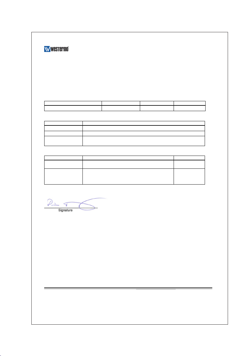
Declaration of Conformity
Org.nr/
Westermo Teleindustri AB
Declaration of conformity
The manufacturer
Herewith declares that the product(s)
Type of product Model Art no
EN 50155 Backbone Routing Switch RFR-212-FB 3641-1640
is in conformity with the following EC directive(s).
No Short name
2004/108/EC Electromagnetic Compatibility (EMC)
2006/95/EC Low voltage (LVD)
2011/65/EU Restriction of the use of certain hazardous substances in electrical and
References of standards applied for this EC declaration of conformity.
No Title Issue
EN 50121-3-2 Railway applications - Electromagnetic compatibility -- Rolling
EN 60950-1 Information technology equipment - Safety -- General
The last two digits of the year in which the CE marking was affixed: 13
Westermo Teleindustri AB
SE-640 40 Stora Sundby, Sweden
electronic equipment (RoHS)
stock - Apparatus
requirements
2006
2006
+A11:2009
+A1:2010
+A12:2011
Pierre Öberg
Technical Manager
3rd October 2013
Postadress/Postal address
S-640 40 Stora Sundby 016-428000 016-428001 52 72 79-4 5671-5550 556361-2604 Eskilstuna
Sweden Int+46 16428000 Int+46 16428001
Tel.
Telefax
Postgiro
Bankgiro Corp. identity number Registered office
6641-2223
5
Page 6
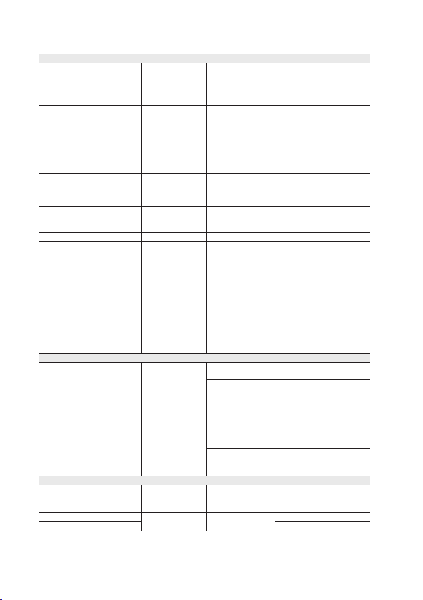
Type tests and environmental conditions
Electromagnetic Compatibility
Phenomena Standard Description Test Levels
ESD EN 61000-4-2 Enclosure contact
RF field AM modulated EN 61000-4-3 Enclosure RF immunity 20 V/m
Fast transients EN 61000-4-4 Signal port immunity ±2 kV
Surges EN 61000-4-5 Power port immunity ±2 kV (L-E)
EN 50155:2001 Power port immunity ±8.4 kV (L-E)
Conducted RF immunity EN 61000-4-6 Signal port immunity 10 V/m
Power frequency magnetic field EN 61000-4-8 Enclosure immunity 300 A/m
Pulsed magnetic field EN 61000-4-9 Enclosure immunity 300 A/m
Voltage interruption EN 50155 Residual voltage 0% 10 ms
Supply overvoltage and undervoltage EN 50155 Overvoltage 140%
Radiated emission EN 55011
Conducted emission EN 55011
Environmental
Temperature Operating –40 to +70°C
Humidity Operating 5 to 95% relative humidity
Altitude Operating 2 000 m / 70 kPa
Reliability prediction (MTBF) MIL-HDBK- 217F Operating 305,000 hours
Vibration IEC 60068-2-64 Operating Vertical 2.0 m/s² Transverse
Shock IEC 60068-2-27 Operating 10 g, 30 ms Half sine ±3 shocks
Packaging
Dimension W x H x D 175 x 100 x 144 mm
Weight 2295 g
Degree of protection IEC 529 Enclosure IP65
Cooling Convection
Mounting Rear panel wall mounting
Limits: EN 50121-3-2
Limits: EN 50121-3-2
IEEE 1478 Operating 20 g, 11 ms Saw tooth ±3 shocks
discharge immunity
Enclosure air discharge
immunity
Power port immunity ±2 kV
Power port immunity 10 V/m
Residual voltage 60%
Enclosure measurement 40 dBµV/m QP
Power port
measurement
Signal port
measurement
Storage & Transport –40 to +85°C
Storage & Transport 5 to 95% relative humidity
Non operating 11.4 m/s²
±6 kV
±8 kV
80 – 2700 MHz
±1 kV (L-L)
±8.4 kV (L-L)
0.15 – 80 MHz
0.15 – 80 MHz
0, 16.7, 50 Hz
100 ms & 1000 ms
100 ms
30 – 230 MHz
47 dBµV/m QP
230 – 1000 MHz
99 dBµV QP
0.15 – 5 MHz
93 dBµV QP
5 – 30 MHz
99 dBµV QP
0.15 – 5 MHz
93 dBµV QP
5 – 30 MHz
(–40 to +158°F)
(–40 to +185°F)
2.0 m/s² Longit. 2.0 m/s²
6
6641-2223
Page 7

Description
Functional description
RFR-212-FB is a switch developed for rail on board and industrial applications, approved
according to EN 50155. To meet the environmental requirements from rail and harsh
industrial applications the switch is equipped with rugged M12 Ethernet connectors and
full metal housing and it fulfills IP 65 ingress protection. The unique FRNT (Fast Recovery
of Network Topology) technology is the fastest protocol on the market to re-configure
a network in the event of any failure of a link or hardware. RFR-212-FB supports QoS
(Quality of Service) with four priority queues and strict priority scheduling as well as
HoL (Head of Line Blocking Prevention), in order to assure a deterministic behaviour
of the network. In the event of power loss or other switch failure, the RFR-212-FB is
equipped with dual by-pass relays which can maintain communication through the switch
of dual backbone links.
6641-2223
7
Page 8

Interface specifications
Power
Rated voltage 24 to 110 VDC
Operating voltage 16.8 to 143 VDC
(14.4 to 154 VDC for 100 ms)
Rated current
(using Westermo USB plug)
Inrush current 5 mA²s @ 24 VDC
Startup current
(Power source capability)
Polarity Reverse polarity protected
Redundant power input No
Isolation to All interfaces and chassis
Galvanic connection to None
Connection M12 A-coded male
Connector size 0.2 – 2.5 mm² (AWG 24 – 13)
Shielded cable Not required
Shielded cable Not required
Miscellaneous –
470 mA @ 24 VDC
130 mA @ 110 VDC
79 mA²s @ 110 VDC
600 mA @ 24 VDC
250 mA @ 110 VDC
M12 A-Coded Power Connector
Position Direction Description
1 U+ Positive supply voltage
2 – –
3 0 V 0 V
4 – –
Housing Shield Chassis of product (ground)
8
2 1
3 4
6641-2223
Page 9

Ethernet TX (both switch, router and coupler ports)
Electrical specification IEEE std 802.3. 2000 Edition
Data rate 10 Mbit/s or 100 Mbit/s, manual or auto
Protocol –
Duplex Full or half, manual or auto
Circuit type TNV-1
Transmission range 100 m (328 ft)
Isolation to All interfaces and chassis
Galvanic connection to None
Connection M12 D-coded
Shielded cable Yes
Conductive housing Yes
Miscellaneous –
FRNT reconfiguration time Typically below 20 ms
Number of ports 12
M12 D-coded, 10/100Base-TX
Position Direction Description
1 Out Transmit Data +
2 In Receive Data +
3 Out Transmit Data –
4 In Receive Data –
Housing Shield Chassis of product (ground)
6641-2223
9
Page 10

Configuration backup device
Electrical specification USB
Memory size 16 Mbyte
Protocol USB v1.1
Connection M12 A-coded female (on switch side)
Isolation to All interfaces, but not to chassis
Shielded cable NA
Miscellaneous –
USB / Configuration
Pin number Signal
No 1 DN
No 2 VBUS
No 3 NC
No 4 DP
No 5 GND
The agency approvals and standards compliance of the RFR-212-FB are valid with
the WESTERMO USB configuration plug 3641-0190 attached. Only WESTERMO USB
plugs are allowed for use together with this product.
10
6641-2223
Page 11

Location of Interface ports, LED's
USB / Configuration
LED indicators
Earth connect
LED indicators
Ethernet
LED indicators
6641-2223
Power
11
Page 12

LED indicators
LED Status Description
ON OFF Unit has no power.
GREEN All OK, no alarm condition.
RED Alarm condition, or until unit has started up.
BLINK Location indicator ("Here I am!"). Activated when connected to IPConfig Tool,
FRNT OFF FRNT disabled.
GREEN FRNT OK.
RED FRNT Error.
BLINK Unit configured as FRNT Focal Point.
RSTP OFF RSTP disabled.
GREEN RSTP enabled.
BLINK Unit selected as RSTP root switch.
USR 1 OFF (Configurable) VPN disabled.
GREEN (Configurable) Default: At least one VPN tunnel up and OK.
RED (Configurable) Default: All VPN tunnels down.
X1 to X12 OFF No Link.
GREEN Link established.
GREEN FLASH Data traffic indication.
YELLOW Port alarm and no link. Or if FRNT, RSTP or Link Aggregation mode,
(Alarm conditions are configurable, see ''WeOS Management Guide'').
or upon request from Web or CLI.
port is blocked.
12
6641-2223
Page 13

By-Pass functionality
The by-pass functionality in RFR-212-FB secures connection in case of power failure in
one of the switches. If a switch has power loss an internal relay in RFR-212-FB will bypass the switch and bridge two Ethernet ports.
By-pass interfaces
In case of power failure X9 will be by-passed to X11 and X10 will be by-passed to X12.
Internally the switch will bypass
X9.1
X9.2 X11.1
X9.3 X11.4
X9.4 X11.3
X10.1 X12.2
Connected to
X10.2 X12.1
X10.3 X12.4
X10.4 X12.3
Note! When by-passing a switch, approximately 5 m (16.4 ft) of the transmission range
(100 m, 328 ft) is consumed. As an example, if a network is intended to cope with a
single car blackout scenario and that two RFR-212-FB in that case will be by-passed, the
total cable distance through the blackout car to adjacent switches on each side of the
blackout car, should not exceed 90 m. (295 ft) Normally, RFR-212-FB can handle longer
distances, up to 150 m (492 ft), but this can not be guaranteed and has to be investigated
case by case. Cable length data is valid for cat5e cable.
X11.2
X9
X11
X12
Switch 1 Switch 2 Switch 3
X11
X12
X10
X9
X10
6641-2223
13
Page 14

Mounting
There are four 6 mm bore holes intended for mounting the unit. The unit can be mounted vertical or horizontal. Use four M5 screws with 12 mm washer on a flat and stable
surface.
Connection of cables
Recommended tightening torque for the M12 connectors: 0.6 Nm.
Removal
Disconnect all cables and unscrew the unit from the wall.
Time For Replacement < 15 minutes.
Cooling
This unit relies on convection cooling. Make sure that it is installed so that the ambient
temperature is within the specified temperature range, e.g. by avoiding obstruction of
the airflow around the unit.
14
6641-2223
Page 15

Dimensions
142 ±1 11 ±1
164 ±1
175 ±1
22 ±1
28 ±0,5
M5
2,5 ±0,5
100 ±1
56 ±0,5
6,5
-0
0,5
(4x)
0
24,5
15,5
31
46,5
62
77,5
93
0
18,4
36,8
55,2
22,4
11,5 ±0,5
3 ±0,5
133,0 ±1,5
144,5 ±1,5
ToDu
130225
Created
01
PaPu
Approved
Date
Rev
Designer
Description
Measurements are stated in millimeters.
6641-2223
15
Page 16

Getting Started
This product runs Westermo Operating System (WeOS) which provides several
management tools that can be used for configuration of the unit.
• IPConfig tool
This is a custom Westermo tool used for discovery of attached Westermo units.
• Web
Configuration of the unit using the web browser.
• CLI
Configuration of the unit via the Command Line Interface.
If the computer is located in the same subnet as the switch you can easily use a web
browser to configure the unit. Within the web you can configure most of the available
functions.
For advanced network settings and more diagnostic information, please use the CLI.
Detailed documentation is available in the chapter ”The Command Line Management
Tool” in the WeOS management guide.
Factory default IP address: 192.168.2.200
Netmask: 255.255.255.0
Gateway: Disabled
Note! If you are not sure about the subnet – consult your network administrator.
Configuration
Configure the unit from a web browser
The unit can easily be configured from a web browser.
Open the link http://192.168.2.200 in your web browser, and you will be prompted with
a Login screen, where the default settings for Username and Password are:
Username: admin
Password: westermo
Once you have logged in, you can use the extensive integrated help function describing
all configuration options. Two common task when configuring a new switch is to assign
appropriate IP settings, and to change the password of the admin account.
The password can be up to 64 characters long, and should consist of printable ASCII
characters (ASCII 33-126); 'Space' is not a valid password character.
Note! Version of IP Config tool must be 10.4 or higher.
16
6641-2223
Page 17

Referring documents
Type Description Document number
Management Guide Westermo OS management guide
6101-3201
Factory reset
It is possible to set the unit to factory default settings by using Ethernet M-12 cables.
1. Power off the switch and disconnect all Ethernet cables.
2. Connect the first Ethernet cable between Ethernet port X1 and Ethernet port X6.
Then connect the second Ethernet cable between Ethernet port X2 and Ethernet
port X5.
The ports need to be connected directly by an Ethernet cable, i.e., not via a hub or
switch. Use a straight cable – not a cross-over cable – when connecting the ports.
3. Power on the unit.
4. Wait for the unit to start up. Control that the ON LED is flashing red.
The ON LED flashing indicates that the unit is now ready to be reset to factory
default. You now have the choice to go ahead with the factory reset, or to skip
factory reset and boot as normal.
• Go ahead with factory reset:
Acknowledge that you wish to conduct the factory reset by unplugging one of the
Ethernet cables. The ON LED will stop flashing.
This initiates the factory reset process*, and the unit will restart with factory default
settings. When the switch has booted up, the ON LED will show a green light, and is
now ready to use.
• Skip the factory reset:
To skip the factory reset process, just wait for approximately 30 seconds
(after the ON LED starts flashing RED) without unplugging the Ethernet cables.
The switch will conduct a normal boot with the existing settings.
* Note Do not power off the unit while the factory reset process is in progress.
6641-2223
17
Page 18

Page 19

Page 20

Westermo • SE-640 40 Stora Sundby, Sweden
Tel +46 16 42 80 00 Fax +46 16 42 80 01
Sales Units
Westermo Data Communications
E-mail: info@westermo.com
www.westermo.com
China
sales.cn@westermo.com
www.cn.westermo.com
France
infos@westermo.fr
www.westermo.fr
Germany
info@westermo.de
www.westermo.de
For complete contact information, please visit our website at www.westermo.com/contact or scan the QR code
REV.B 6641-2223 2015-01 Westermo Teleindustri AB, Sweden – A Beijer Electronics Group Company
North America
info@westermo.com
www.westermo.com
Singapore
sales@westermo.com.sg
www.westermo.com
Sweden
info.sverige@westermo.se
www.westermo.se
United Kingdom
sales@westermo.co.uk
www.westermo.co.uk
Other Offices
 Loading...