

Westermo RedFox-5528-T28G-LV, RedFox-5528-E-T28G-LVa, RedFox-5528-T28G-HV, RedFox-5528-E-T28G-HVa, RedFox-5528-F4G-T24G-LV User Manual
...Page 1

www.westermo.com
WeOS
RedFox 5528 Series
Industrial routing switches
Page 2

Table of Contents
1. General Information ........................................................................ 3
1.1. Legal Information ................................................................... 3
1.2. About This Guide ................................................................... 3
1.3. Software Tools ...................................................................... 3
1.4. License and Copyright for Included FLOSS ................................. 3
1.5. WeOS Management Guide ...................................................... 3
2. Safety and Regulations ................................................................... 4
2.1. Warning Levels ..................................................................... 4
2.2. Safety Information ................................................................. 5
2.3. Care Recommendations ......................................................... 6
2.4. Maintenance ......................................................................... 7
2.5. Fibre Optics Handling ............................................................. 7
2.6. Cleaning Optical Connectors .................................................... 7
2.7. Product Disposal ................................................................... 7
2.8. Compliance Information .......................................................... 8
2.8.1. Agency Approvals and Standards Compliance .................... 8
2.8.2. FCC Part 15.105 Notice ................................................. 8
2.8.3. Corrosive Environment .................................................. 8
2.8.4. Simplified Declaration of Conformity .................................. 9
3. Product Description ...................................................................... 10
3.1. Product Description .............................................................. 10
3.2. Available Models ................................................................. 10
3.3. Hardware Overview ............................................................. 11
3.4. Connector Information .......................................................... 11
3.4.1. Power Input and I/O ..................................................... 11
3.4.2. I/O Connection ........................................................... 12
3.4.3. Console Port .............................................................. 13
3.4.4. SFP Transceivers ........................................................ 13
3.5. LED Indicators .................................................................... 14
3.6. Dimensions ........................................................................ 15
4. Installation .................................................................................. 16
4.1. Mounting ........................................................................... 16
4.1.1. Rack Mounting ........................................................... 16
4.1.2. Wall Mounting ............................................................ 16
4.2. Earth Connection ................................................................. 17
4.3. Cooling .............................................................................. 17
5. Specifications .............................................................................. 18
5.1. Interface Specifications ......................................................... 18
5.2. Type Tests and Environmental Conditions ................................. 21
6. Revision Notes ............................................................................ 24
2 RedFox 5528 Series
Page 3

1. General Information
1.1. Legal Information
The contents of this document are provided “as is”. Except as required by applicable law,
no warranties of any kind are made in relation to the accuracy and reliability or contents of
this document, either expressed or implied, including but not limited to the implied
warranties of merchantability and fitness for a particular purpose. Westermo reserves the
right to revise this document or withdraw it at any time without prior notice.
Under no circumstances shall Westermo be responsible for any loss of data or income or
any special, incidental, and consequential or indirect damages howsoever caused.
More information about Westermo can be found at www.westermo.com.
1.2. About This Guide
This guide is intended for installation engineers and users of the Westermo products.
It includes information on safety and regulations, a product description, installation
instructions and technical specifications.
1.3. Software Tools
Related software tools are available at www.westermo.com/support/software-tools.
1.4. License and Copyright for Included FLOSS
This product includes software developed by third parties, including Free/Libre Open
Source Software (FLOSS). The specific license terms and copyright associated with the
software are included in each software package respectively. Please visit the product web
page for more information.
Upon request, the applicable source code will be provided. A nominal fee may be charged
to cover shipping and media. Please direct any source code request to your normal sales or
support channel.
1.5. WeOS Management Guide
This product runs WeOS (Westermo Operating System). Instructions for quick start,
configuration, factory reset and use of USB port are found in the WeOS Management
Guide at www.westermo.com.
RedFox 5528 Series 3
Page 4
2. Safety and Regulations
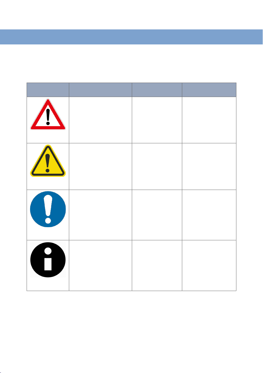
2.1. Warning Levels
Warning signs are provided to prevent personal injuries and/or damages to the product.
The following levels are used:
Level of warning
WARNING
CAUTION
NOTICE
Description Consequence
Indicates a potentially
hazardous situation
Indicates a potentially
hazardous situation
Provides information in order
to avoid misuse of the
product, confusion or
misunderstanding
Used for highlighting general,
but important information
personal injury
Possible death or major
injury
Minor or moderate
injury
No personal injury Minor damage to the
No personal injury Minor damage to the
Consequence
material damage
Major damage to the
product
Moderate damage to the
product
product
product
NOTE
Table 1. Warning levels
4 RedFox 5528 Series
Page 5
2.2. Safety Information
Before installation:
Read this manual completely and gather all information available on the product. Make sure
it is fully understood. Check that your application does not exceed the safe operating
specifications for the product.
This product should only be installed by qualified personnel.
This product should be built-in to an apparatus cabinet or similar, where access is
restricted to service personnel only.
The power supply wiring must be sufficiently fused, and if necessary, it must be possible to
disconnect it manually from all power supply. Ensure compliance to national installation
regulations.
This product relies on convection cooling. To avoid obstruction of the airflow around the
product, follow the spacing recommendations. See Cooling chapter.
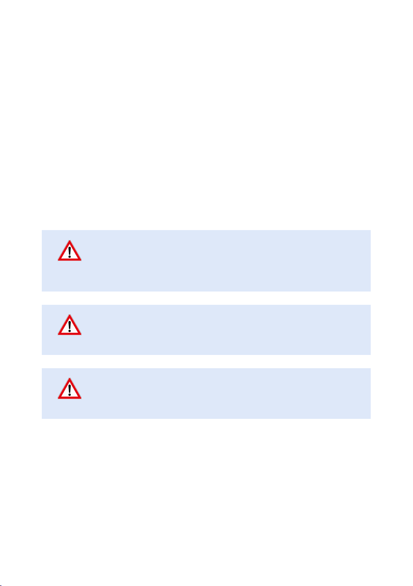
WARNING - PROTECTIVE EARTHING
Before powering up, a protective earthing conductor must be connected
to the protective earthing terminal and have a cross-sectional area of at
least 4 mm2.
WARNING - PREVENT ACCESS TO HAZARDOUS VOLTAGE
Before mounting, using or removing this product: Prevent access to
hazardous voltage by disconnecting the product from all power supply.
WARNING - HAZARDOUS VOLTAGE
Do not open the connected product. Hazardous voltage may occur within
this product when connected to power supply.
RedFox 5528 Series 5
Page 6

WARNING - PREVENT ACCESS TO HAZARDOUS VOLTAGE
1
2 3
CABLE
Apply the protective cap (delivered with the HV product) on the power
cable, according to the illustrated steps below. To prevent accidentally
pulling out wires, make sure the power cable and the wires are firmly
attached to the protective cap. For screw connectors, make sure the
screws are properly tightened, as well as routing the wires separately from
other wires.
CAUTION - CLASS 1 LASER PRODUCT
Do not look directly info a fibre optical port or any connected fibre,
although the product is designed to meet the Class 1 Laser regulations
and complies with 21 CFR 1040.10 and 1040.11.
CAUTION - CORROSIVE GASES
If the product is placed in a corrosive environment, it is important that all
unused connector sockets are protected with a suitable plug, in order to
avoid corrosion attacks on the gold plated connector pins.
NOTICE - REDUCE RISK OF FIRE
To reduce the risk of fire, use only No. 26 (e.g. 24 AWG) UL listed or
CSA certified Telecommunication Line Cord.
2.3. Care Recommendations
Follow the care recommendations below to maintain full operation of the product and to
fulfill the warranty obligations:
6 RedFox 5528 Series
Page 7

• Do not drop, knock or shake the product. Rough handling above the specification may
cause damage to internal circuit boards.
• Do not use harsh chemicals, cleaning solvents or strong detergents to clean the product.
• Do not paint the product. Paint can clog the product and prevent proper operation.
If the product is not working properly, contact the place of purchase, nearest Westermo
distributor office or Westermo Tech support.
2.4. Maintenance
No maintenance is required, as long as the product is used as intended within the specified
conditions.
2.5. Fibre Optics Handling
Fibre optics equipment need special treatment. It is very sensitive to dust and dirt. If the
fibre will be disconnected from the product, the protective hood on the transmitter/
receiver must be connected. The protective hood must be kept on during transportation.
The fibre optics cable must also be handle the same way.
If these recommendations are not followed, the warranty might be at risk.
2.6. Cleaning Optical Connectors
In the event of contamination, the optical connectors should only be cleansed with
recommended cleaning fluids and correct cleaning equipment. Recommended cleaning
fluids:
• Methyl, ethyl, isopropyl or isobotyl alcohol
• Hexane
• Naphtha
2.7. Product Disposal
This symbol means that the product shall not be treated as unsorted municipal waste when
disposing of it. It needs to be handed over to an applicable collection point for recycling
electrical and electronic equipment.
By ensuring the product is disposed of correctly, you will help to reduce hazardous
substances and prevent potential negative consequences to both environment and human
health, which could be caused by inappropriate disposal.
Figure 1. WEEE symbol for treatment of product disposal
RedFox 5528 Series 7
Page 8

2.8. Compliance Information
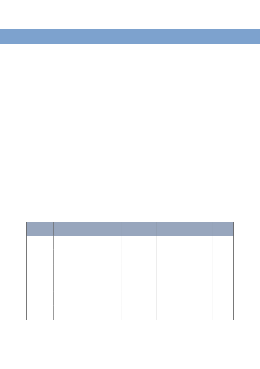
2.8.1. Agency Approvals and Standards Compliance
Type
EMC • EN 50121-4/IEC 62236-4, Railway signalling and telecommunications apparatus
Safety • EN/IEC/UL 60950-1, IT equipment
Approval/Compliance
• EN 61000-6-1, Immunity residential environments
• EN 61000-6-2, Immunity industrial environments
• EN 61000-6-3, Emission residential environments
• EN 61000-6-4, Emission industrial environments
Table 2. Agency approvals and standards compliance
2.8.2. FCC Part 15.105 Notice
This product has been tested and found to comply with the limits for a Class B digital
device, pursuant to Part 15 of the FCC Rules. These limits are designed to provide
reasonable protection against harmful interference in a residential installation. This product
generates, uses and can radiate radio frequency energy and, if not installed and used in
accordance with the instructions, may cause harmful interference to radio communications.
However, there is no guarantee that interference will not occur in a particular installation.
If this product does cause harmful interference to radio or television reception, which can
be determined by turning the product off and on, the user is encouraged to try to correct
the interference by one or more of the following measures:
• Reorient or relocate the receiving antenna
• Increase the separation between the unit and receiver
• Connect the product into an outlet on a circuit different from that to which the receiver
is connected
• Consult the dealer or an experienced radio/TV technician for help
2.8.3. Corrosive Environment
This product has been successfully tested in a corrosion test according to IEC 60068- 2-60,
method 3. This means that the product meets the requirements to be placed in an
environment classified as ISA-S71.04 class G3.
CAUTION - CORROSIVE GASES
If the product is placed in a corrosive environment, it is important that all
unused connector sockets are protected with a suitable plug, in order to
avoid corrosion attacks on the gold plated connector pins.
8 RedFox 5528 Series
Page 9

2.8.4. Simplified Declaration of Conformity
Hereby, Westermo declares that this product is in compliance with applicable EU
directives. The full EU declaration of conformity and other detailed information is available
at www.westermo.com/support/product-support.
Figure 2. The European conformity marking
RedFox 5528 Series
9
Page 10
3. Product Description
3.1. Product Description
The RedFox industrial rack is a high performance industrial Ethernet switch designed for
high network traffic applications. Various port configurations are available that can be
further customised with SFP transceivers. RedFox is powered by WeOS, the Westermo
network operating system.
RedFox-5528 is designed for 19” cabinet according to the ETSI standard, which makes it
suitable for use in control room networks as well as for cabinets installed along railway
trackside installations. RedFox-5528 is designed to run efficiently from a DC power supply
(not considered DC mains). The unit is also equipped with configurable I/O fault contact
that makes it ideal for easy installations and monitoring in industrial applications.
Only industrial grade components are used, which gives Redfox- high MTBF hours that
ensures a long service life. A wide operating temperature range of -40 to +74°C (-40 to
+165°F) can be achieved with no moving parts or cooling holes in the case. RedFox has
been tested both by Westermo and external test labs to meet many standards regarding
EMC, isolation, climate, vibration and shock, all to the highest levels suitable for heavy
industrial environments and rail trackside application.
WeOS has been developed to allow offer cross platform and future-proof solutions. WeOS
can deliver 20 ms ring recovery performance even for networks with video or EtherNet/IP
traffic. For more WeOS functionality, please see the WeOS datasheet.
3.2. Available Models
Art. no.
3641-4500
3641-4400
3641-4505
3641-4405
3641-4510
3641-4410
3641-4515
3641-4415
3641-4520
3641-4420
3641-4525
3641-4425
a
Selective sales approval, contact Westermo before ordering
Model No. of
RedFox-5528-T28G-LV
RedFox-5528-E-T28G-LV
RedFox-5528-T28G-HV
RedFox-5528-E-T28G-HV
RedFox-5528-F4G-T24G-LV
RedFox-5528-E- F4G-T24G-LV
RedFox-5528-F4G-T24G-HV
RedFox-5528-E-F4G-T24G-HV
RedFox-5528-F16G-T12G-LV
RedFox-5528-E-F16G-T12G-LV
RedFox-5528-F16G-T12G-HV
RedFox-5528-E-F16G-T12G-HV
a
a
copper ports
a
a
a
a
28 - 24-48
28 - 48-110
24 4 24-48
24 4 48-110
12 16 24-48
12 16 48-110
10 RedFox 5528 Series
No. of SFP
ports
HV
VDC
VDC
VDC
LV
VDC
VDC
VDC
Page 11
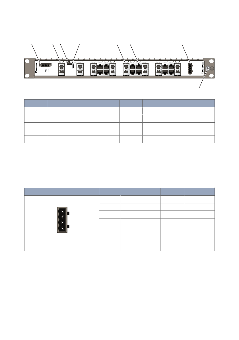
3.3. Hardware Overview
Digital in-
Digital in+
NONCC
Status
DC1
DC2
FRNT
RSTP/USR1
USR2
CONSOLE
SD
ON
321 4 5 6 7 8 9 10 11 12 13 14 15 16 17 16 19 20 21 22 23 24 25 26 27 28
+DC1
+DC2
COM
COM
POWER
I/O
2 41 5 7
8
3 6
1
2
3
4
No. Description No. Description
1 I/O connection 2 LED indicators
3 Console port 4 Micro SD
5 100/1000 Mbit/s SFP slots (number
depending on model)
6 10/100/1000 Mbit/s TX ports (number
depending on model)
7 Power Input 8 Protective earth
Figure 3. Location of interface ports and LED indicators, illustrated by a RedFox-5528-F16G-T12G
3.4. Connector Information
3.4.1. Power Input and I/O
Illustration
Position Product marking Direction Description
1 +DC1 Input Supply voltage
2 +DC2 Input Supply voltage
3 -COM Input Common
4 -COM Input Common
Table 3. Power input and I/O
RedFox 5528 Series 11
Page 12

WARNING - PREVENT ACCESS TO HAZARDOUS VOLTAGE
1
2 3
1
2
3
4
Digital in-
Digital in+
NO
NC
C
Status
5
CABLE
Apply the protective cap (delivered with the HV product) on the power
cable, according to the illustrated steps below. To prevent accidentally
pulling out wires, make sure the power cable and the wires are firmly
attached to the protective cap. For screw connectors, make sure the
screws are properly tightened, as well as routing the wires separately from
other wires.
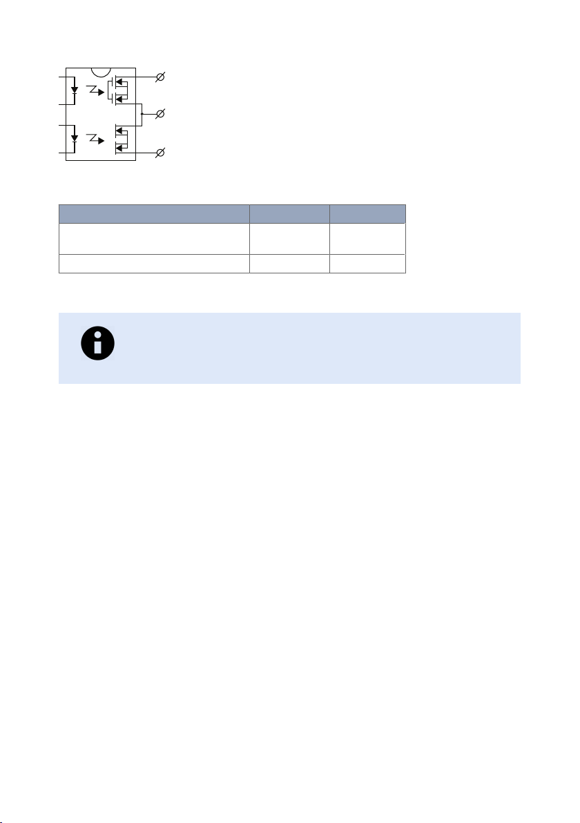
3.4.2. I/O Connection
Illustration
Pin no. Product marking Direction Description
1 Digital in- Input Digital in-
2 Digital in+ Digital in+
3 Status NO Output Alarm (status) relay contact
4 Status C
5 Status NC
Table 4. I/O connection
The Digital in is an opto-isolated digital input, which can be used to monitor external
events.
The Status output is a potential free, opto-isolated, alternation (Form-C) solid-state relay.
This can be configured to monitor various alarm events within the RFIR unit, see WeOS
Management Guide. An external load in series with an external DC or AC voltage source is
required for proper functionality.
12 RedFox 5528 Series
Page 13
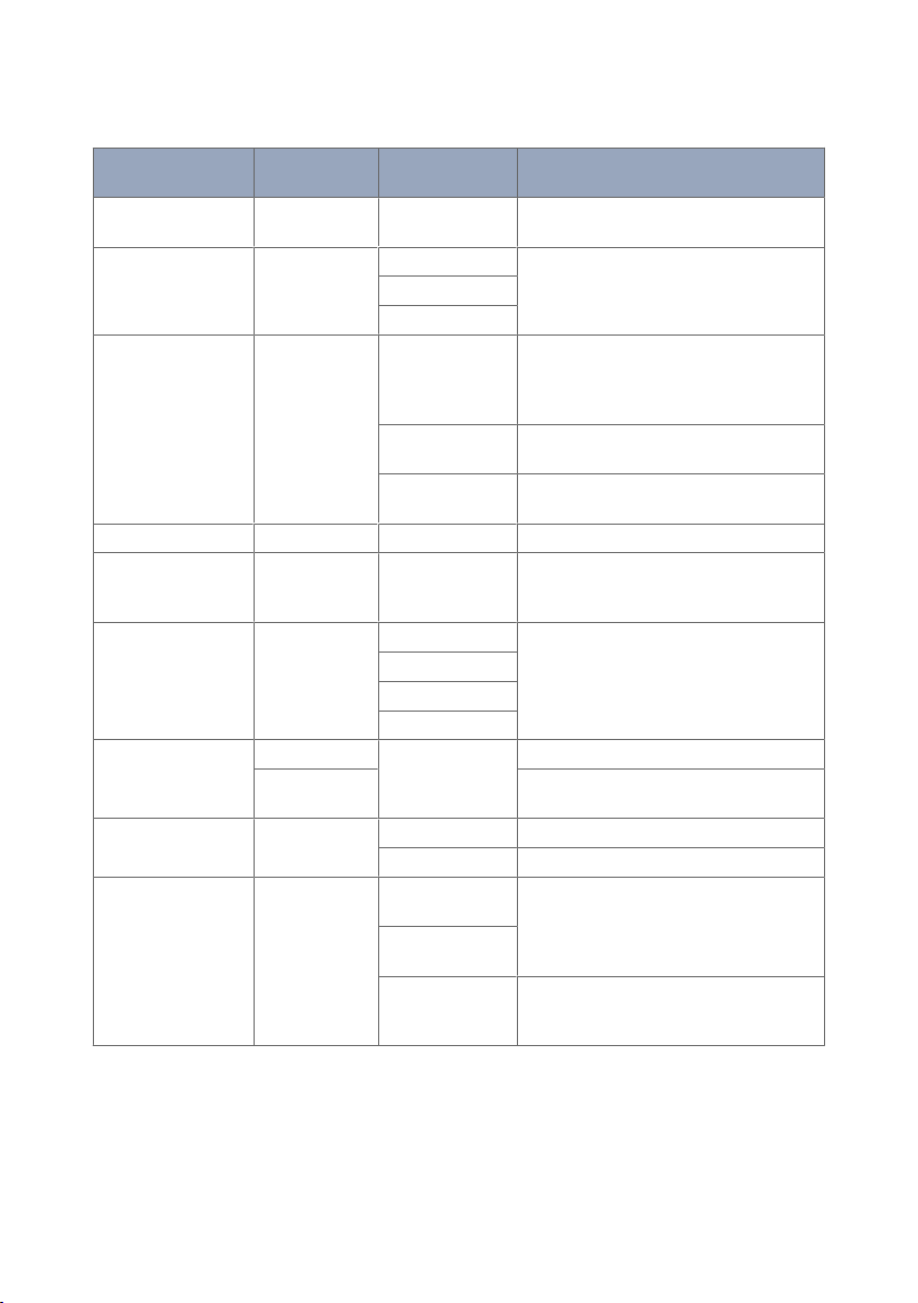
NC
C
NO
Normally Closed pole
Normally Open pole
Figure 4. Status output
Unit condition
Unpowered / pre-operational or Alarm
active
Operational and Alarm inactive CLOSED OPEN
Status NO- C Status NC-C
OPEN CLOSED
Table 5. Status output
NOTE
Digital In-, Digital In+ and Status NO/C are backward compatible with
RFIR-x19/27 products.
3.4.3. Console Port
The console port can be used to connect to the CLI (Command Line Interface). The
console connector is a micro USB cable that connects to a FTDI FT232R USB to serial
converter internally. For drivers, refer to www.ftdichip.com and download the appropriate
VCP driver
3.4.4. SFP Transceivers
The product supports Westermo labelled transceivers only. See Westermo's modular
transceivers datasheets 100 Mbit and 1 Gbit for supported SFP transceivers for the RedFox
series.
Each SFP slot can hold one SFP transceiver. For supported transceivers, see SFP datasheets.
See "Transceiver User Guide 6100-0000" for transceiver handling instructions.
RedFox 5528 Series 13
Page 14

3.5. LED Indicators
LED Status Description
ON OFF Product has no power
GREEN All OK, no alarm condition
RED Alarm condition, or until product has started
BLINK Location indicator ("Here I am!"). Activated
RSTP/
USR1
FRNT OFF FRNT disabled
DC1 OFF Product has no power
DC2 OFF Product has no power
USR2 Configurable, see WeOS Management Guide
TX/FX
ports
OFF RSTP disabled
GREEN RSTP enabled
BLINK Product selected as RSTP/STP root switch
USR1 Configurable, see WeOS Management Guide
GREEN FRNT OK
RED FRNT error
BLINK Product configured as FRNT focal point
GREEN Power OK on DC1
RED +DC1 input voltage is below operating
GREEN Power OK on DC2
RED +DC2 input voltage is below operating
OFF No link
GREEN Link established
GREEN
FLASH
YELLOW Port alarm and no link. Or if FRNT or RSTP
up. (Alarm conditions are configurable, see
WeOS Management Guide)
when connected to WeConfig tool, or upon
request from web or/and CLI. RED BLINK
during boot indicates pending cable factory
reset.
voltage limit
voltage limit
Data traffic indication
mode, port is blocked.
Table 6. LED indicators
14 RedFox 5528 Series
Page 15

3.6. Dimensions
32
480
462
469
43
Grounding Point Screw M5 x 0.8 mm - Roll tap true all
235
466
18 240
7,2 (4x)
440
411
4
7
DETAIL A
SCALE 1 : 1
Dimensions are stated in mm.
Figure 5. Dimensional drawing
Illustrated by RedFox-5528-F4G-T24G-HV/LV.
RedFox 5528 Series 15
Page 16

4. Installation
CONSOLE
Digital in-
Digital in+
NO
C
NC
Status
I/O
ON
DC1
DC2
FRNT
RSTP/USR1
USR2
24
23
22
21
20
19
18
17
16
15
14
13
12
11
10
9
8
7
6
5
4
3
2
1
28
27
26
25
+DC1
+DC2
COM
COM
POWER
4.1. Mounting
The RedFox Industrial Rack is designed for installation in 19" rack solutions according to
ETSI standard, with a shallow depth of 240 millimetres. RFIR can also be wall mounted as
an installation option.
4.1.1. Rack Mounting
The product can be mounted in all directions inside a 19" apparatus cabinet. Use M6x25 or
1/4x1".
Figure 6. Rack mounted product
4.1.2. Wall Mounting
The product can be wall mounted in all directions. Use maximum 6.4 mm or 1/4" screws.
16 RedFox 5528 Series
Page 17

CONSOLE
Digital in-
Digital in+
NO
C
NC
Status
I/O
SD
ON
DC1
DC2
FRNT
RSTP/USR1
USR2
24
23
22
21
20
19
18
17
16
15
14
13
12
11
10
9
8
7
6
5
4
3
2
1
28
27
26
25
+DC1
+DC2
COM
COM
POWER
Figure 7. Wall mounted product
Digital in-
Digital in+
NONCC
Status
DC1
DC2
FRNT
RSTP/USR1
USR2
CONSOLE
SD
ON
3214
567891011
12
13141516171619
20
212223
24 25 26 27 28
+DC1
+DC2
COM
COM
POWER
I/O
4.2. Earth Connection
For correct function, the earth connection needs to be properly connected to a solid
ground. See the figure below.
Figure 8. Earth connection
4.3. Cooling
For mounting in 19" apparatus cabinet without forced ventilation, a minimal spacing of 1U
according to IEC 60297 or 45 mm (1.75") above/below is recommended. With forced
ventilation, no minimal spacing is required as long as the temperature of the rear cooling
plates does not exceed +85ºC (+185ºF).
For wall mounting in an area without forced ventilation, a minimum spacing of 45 mm
(1.75") above/below and 10 mm (0.4") left/right is recommended. For areas with forced
ventilation, no minimal spacing is required as long as the temperature of the rear cooling
plates does not exceed +85ºC (+185ºF).
RedFox 5528 Series 17
Page 18

5. Specifications
5.1. Interface Specifications
DC, Power port
Rated voltage For LV models: 24-48 VDC
Operating voltage For LV models: 18-60 VDC
Rated current RedFox-5528-(E-)T28G-LV: 1.10 A at 24 VDC
Fuse rating
Component: U2 (LV), U1
(HV)
Rated frequency DC
Inrush current, I²t For all LV-models: 125 mA2s at 24 VDC
Startup current
Polarity Reverse polarity protected
Redundant power input Yes
Isolation All other ports
Connector Detachable screw terminal
Conductor cross section 0.2-2.5 mm² (AWG 24-12)
Stripping length cable 7 mm
Tightening torque, terminal
screw
b
For HV models: 48-110 VDC
For HV models: 36-154 VDC
0.54 A at 48 VDC
RedFox-5528-(E-)T28G-HV: 0.52 A at 48 VDC
RedFox-5528-(E-)F4G-T24G-LV: 1.20 A at 24 VDC
RedFox-5528-(E-)F4G-T24G-HV: 0.54 A at 48 VDC
RedFox-5528-(E-)F16G-T12G-LV: 1.30 A at 24 VDC
RedFox-5528-(E-)F16G-T12GHV:
All models
For all HV-models: 34 mA2s at 48 VDC
2x nominal current
0.5 - 0.6 Nm
a
0.24 A at 110 VDC
0.55 A at 48 VDC
0.24 A at 110 VDC
0.64 A at 48 VDC
0.65 A at 48 VDC
0.28 A at 110 VDC
4A(T)
82 mA2s at 48 VDC
33 mA2s at 110 VDC
18 RedFox 5528 Series
Page 19

DC, Power port
Shielded cable Not required
a
Denote time-delay fuse
b
Recommended external supply current capability for proper startup
I/O connection, Digital input
Isolation to All other ports
Connector Detachable screw terminal
Conductor cross section 0.14 - 1.5 mm² (AWG 28-16)
Stripping length cable 7 mm
Tightening torque, terminal
0.22 - 0.25 Nm
screw
Terminal torque, screw flange 0.3 Nm
Maximum voltage/current 60 VDC, IIN ≤ 2.9 mA at 60 VDC
Voltage levels Logic one: >8 VDC
Logic zero: <5 VDC
I/O connection, Relay output
Connect resistance Maximum 30 Ω
Isolation to All other ports
Connector Detachable screw terminal
Conductor cross section 0.14 - 1.5 mm² (AWG 28-16)
Stripping length cable 7 mm
Tightening torque, terminal
0.22 - 0.25 Nm
screw
Terminal torque, screw flange 0.3 Nm
Maximum voltage/current 60 VDC/80 mA
RedFox 5528 Series 19
Page 20

Ethernet TX
a
Electrical specification IEEE std 802.3
Data rate 10 Mbit/s, 100 Mbit/s, 1000 Mbit/s, manual or auto
Duplex Full or half, manual or auto
Circuit type TNV-1
Transmission range Up to 100 m with CAT5e cable or better
Isolation All other ports
Cabling Shielded cable CAT5e or better is recommended
Conductive chassis Yes
a
10/100/1000 Mbit/s ports are:
RedFox-5528-(E-)T28G-LV and HV: 1-28
RedFox-5528-(E-)F4G-24G-LV and HV: 5-28
RedFox-5528-(E-)F16G-T12G-LV and HV: 7-10, 15-18, 23-26
SFP ports
a
Optical/Electrical specification IEEE std 802.3
Data rate 100 Mbit/s, 1000 Mbit/s
b
Duplex Full or half, manual or auto
Transmission range Depending on transceiver
Connector SFP slot holding fibre transceiver
a
SFP ports are:
RedFox-5528-(E-)F4G-T24G-LV and HV: 1-4
RedFox-5528-(E-)F16G-T12G-LV and HV: 1-6, 11-14, 19-22, 27-28
b
100 Mbit/s or 1000 Mbit/s tranceiver supported
Console port
Electrical specification USB 2.0 device interface
Data rate Up to 480 Mbps (high-speed mode)
Circuit type SELV
Maximum supply current 100 mA
Connector USB Micro B connector in device mode
Micro SD
Electrical specification Secure Digital 2.0
Circuit type SELV
Maximum supply current 100 mA
Connector Micro SD connector
20 RedFox 5528 Series
Page 21
5.2. Type Tests and Environmental Conditions
Environmental
phenomena
ESD EN 61000-4-2 Enclosure Contact: ±6 kV
Fast transients EN 61000-4-4 Power port ± 2 kV
Surge EN 61000-4-5 Power port L-E: ± 1 kV, 12 Ω, 9 µF, 1.2/50 µs
Pulsed magnetic field EN 61000-4-9 Enclosure 300 A/m
Radiated RF
immunity
Conducted RF
immunity
Radiated RF emission CISPR 16-2-3 Enclosure Residential (30-6000 MHz)
Conducted RF
emission
Dielectric strength EN 60950-1 Power port to all
Basic
standard
EN 61000-4-3 Enclosure 20 V/m at (80 MHz to 2 GHz)
EN 61000-4-6 Power por t 10 V, 80% AM, 1 kHz; (0.15-80) MHz
ANSI C63,4 FCC Part 15 B, Class B
CISPR 16-2-1 Power por t Class B
Description
I/O ports
Earth por t
I/O port L-E: ± 2 kV, 42 Ω, 0.5 µF, 1.2/50 µs
Ethernet (shield
on cable)
Ethernet ports
Earth por t
I/O port
Ethernet ports EN 61000-6-3
other ports
Ethernet ports to
all other ports
Gbps Ethernet
ports to all other
ports
Test levels
Air: ±8 kV
L-E: ± 2 kV, 42 Ω, 0,5 µF, 1.2/50 µs
L-L: ± 0,5 kV, 2 Ω, 18 µF, 1.2/50 µs
L-L: ± 1 kV, 42 Ω, 0,5 µF, 1.2/50 µs
L-L: ± 1 kV, 42 Ω, 0.5 µF, 1.2/50 µs
L-E: ± 2 kV, 2 Ω, 1.2/50 µs
10 V/m at (2-6 GHz)
1 kHz sine, 80% AM
(30 MHz -25.5 GHz)
1500 VAC rms, 60 s
1500 VAC rms, 60 s
Table 7. EMC and electrical conditions
RedFox 5528 Series 21
Page 22

Environmental
phenomena
Basic
standard
Temperatures EN 60068-2-1
EN 60068-2-2
Description
Test levels
Operating -40 to +74°C (-40 to +165°F)
Storage and
-50 to +85°C (-58 to +185°F)
a
transport
Humidity EN 60068-2-30 Operating 5-95% relative humidity
Storage and
transport
Corrosive gases IEC
Operating Method 3, 21 days
b
60068-2-60
Altitude Operating 2000 m/70 kPa
Service life Operating 20 years according to IEC/TR 62380
MTBF MIL-HDBK
217F
RedFox-5528-F4G-T24G-HV: 381,000
hours
RedFox-5528-F4G-T24G-LV: 371,000
hours
RedFox-5528-F16G-T12G-HV: 397,000
hours
RedFox-5528-F16G-T12G-LV: 386,000
hours
RedFox-5528-T28G-HV: 366,000 hours
RedFox-5528-T28G-LV: 356,000 hours
Telcordia RedFox-5528-F4G-T24G-HV: 667,000
hours
RedFox-5528-F4G-T24G-LV: 643,000
hours
RedFox-5528-F16G-T12G-HV: 735,000
hours
RedFox-5528-F16G-T12G-LV: 706,000
hours
RedFox-5528-T28G-HV: 643,000 hours
RedFox-5528-T28G-LV: 620,000 hours
Vibration IEC 60068-2-6
Operational 2 g rms 5-500 Hz, 5 sweeps
(sine)
IEC
60068-2-64
(random)
Operational,
endurance test
12 dB/octave, 2-13.2 Hz, 0.011 g2/Hz,
13.2-100 Hz, 1.0 grms, 150 minutes per
axis
5-2000 Hz, rms 2.3 m/s2 ,1.5h
Shock IEC
Operational 30 g, 11 ms
60068-2-27
Enclosure EN 60950-1 Aluminum Fire enclosure
Weight 3.8 kg
Degree of protection EN 60529 Enclosure IP40
22 RedFox 5528 Series
Page 23

Environmental
phenomena
Basic
standard
Description
Test levels
Cooling Convection
a
Refer to "Safety and Regulations" chapter regarding touch temperature
b
Method 3, 21 days corresponds to Harsh Industrial Environment G3 which is defined in ANSI/ISA 17.04: 2015
Table 8. Environmental and mechanical conditions
RedFox 5528 Series 23
Page 24

6. Revision Notes
Revision
Rev. D 2019-06 Product name change throughout the user guide. USB port removed in
Rev. C 2018-10 2.2 New warning added, 2.7 Environmental protection updated to
Rev. B 2017-11 2.2 Safety information; Caution - Class 1 laser product updated, 2.3 Care
Rev. A 2017-07 First issue of the user guide
Date Change description
illustrations and information. "Unit" changed to "product".
1.3 Software tools updated, 2.1 Warning levels updated (Caution), 2.2
Safety information updated, 2.3 Care recommendations updated, 2.5 Fibre
optic handling updated, 2.7 Product disposal updated, 2.8.1 Agency
approvals and standard compliance updated, 2.8.4 Simplified declaration of
conformity updated, 3.1 Product description updated, 3.2 Available models
updated, 3.3 Hardware overview updated, 3.4.1 Power input and I/O
updated, 3.5 LED indicators updated, 3.6 Dimensions updated, 5.1
Interface specifications updated, 5.2 Type test and environmental
conditions updated
Product disposal, 2.8.1 Agency approvals updated, 2.8.3 Corrosive gases
upgraded to Caution instead of Notice, 2.8.4 DoC updated, 3.1 Text
updated, 3.4.1 Warning updated with illustrations, 3.4.4 Figure 3 deleted
(old), 5.1 Fuse rating updated
Recommendations updated, 2.8.3 new chapter added, 3.3 text added, 5.1
Interface Specifications updated - inrush current, SFP por ts, 5.2 Type Tests
and Environmental Conditions updated - Surge updated, Corrosive gased
added, Vibration updated, Radiated RF emission and Conducted RF
emission updated
24 RedFox 5528 Series
Page 25

RedFox 5528 Series
Page 26

RedFox 5528 Series
Page 27

RedFox 5528 Series
Page 28

Westermo • SE-635 35 Stora Sundby, Sweden
Tel +46 16 42 80 00 Fax +46 16 42 80 01
E-mail: info@westermo.com
www.westermo.com
6641-22820 REV D 2019 06 Westermo Network Technologies AB, Sweden
 Loading...