

Page 1
RedFox Series
WeOS
Wolverine Series
Lynx Series
Falcon Series
Viper Series
Westermo OS
6101-3201
Management Guide
©
Westermo Teleindustri AB
www.westermo.com
Page 2

Westermo OS Management Guide
Version 4.17.0-0
Legal information
The contents of this document are provided ”as is”. Except as required by applicable law, no warranties of any kind, either express or implied, including, but not
limited to, the implied warranties of merchantability and fitness for a particular
purpose, are made in relation to the accuracy and reliability or contents of this
document. Westermo reserves the right to revise this document or withdraw it at
any time without prior notice.
Under no circumstances shall Westermo be responsible for any loss of data or
income or any special, incidental, and consequential or indirect damages howsoever caused. More information about Westermo can be found at the following
Internet address: http://www.westermo.com
2
©
2015 Westermo Teleindustri AB
Page 3

Westermo OS Management Guide
Version 4.17.0-0
Contents
Legal information 2
Table of Contents 3
I Introduction to WeOS and its Management Methods 9
1 Introduction 10
1.1 Westermo and its WeOS products . . . . . . . . . . . . . . . . . . . . . 10
1.2 Getting Started . . . . . . . . . . . . . . . . . . . . . . . . . . . . . . . . . 10
1.3 Introduction to WeOS . . . . . . . . . . . . . . . . . . . . . . . . . . . . . 11
1.4 How to read this document . . . . . . . . . . . . . . . . . . . . . . . . . 11
1.5 Westermo products running WeOS . . . . . . . . . . . . . . . . . . . . 13
2 Quick Start 15
2.1 Starting the Switch for the First Time . . . . . . . . . . . . . . . . . . . 15
2.2 Modifying the IP Setting . . . . . . . . . . . . . . . . . . . . . . . . . . . 16
3 Overview of Management Methods 28
3.1 When to use the WeConfig tool . . . . . . . . . . . . . . . . . . . . . . . 29
3.2 When to use the Web . . . . . . . . . . . . . . . . . . . . . . . . . . . . . 29
3.3 When to use the CLI . . . . . . . . . . . . . . . . . . . . . . . . . . . . . . 30
4 Management via Web Interface 32
4.1 Document Conventions . . . . . . . . . . . . . . . . . . . . . . . . . . . . 33
4.2 Logging in . . . . . . . . . . . . . . . . . . . . . . . . . . . . . . . . . . . . 34
4.3 Navigation . . . . . . . . . . . . . . . . . . . . . . . . . . . . . . . . . . . . 36
4.4 System Overview . . . . . . . . . . . . . . . . . . . . . . . . . . . . . . . 39
5 Management via CLI 45
©
2015 Westermo Teleindustri AB 3
Page 4

Westermo OS Management Guide
Version 4.17.0-0
5.1 Overview of the WeOS CLI hierarchy . . . . . . . . . . . . . . . . . . . 45
5.2 Accessing the CLI . . . . . . . . . . . . . . . . . . . . . . . . . . . . . . . 47
5.3 Using the CLI . . . . . . . . . . . . . . . . . . . . . . . . . . . . . . . . . . 51
5.4 General CLI commands . . . . . . . . . . . . . . . . . . . . . . . . . . . . 57
6 WeOS SNMP Support 61
6.1 Introduction and feature overview . . . . . . . . . . . . . . . . . . . . . 61
6.2 Managing SNMP via the web interface . . . . . . . . . . . . . . . . . . 71
6.3 Manage SNMP Settings via the CLI . . . . . . . . . . . . . . . . . . . . 74
II Common Switch Services 78
7 General Switch Maintenance 79
7.1 Overview . . . . . . . . . . . . . . . . . . . . . . . . . . . . . . . . . . . . . 79
7.2 Maintenance via the Web Interface . . . . . . . . . . . . . . . . . . . . 115
7.3 Maintenance via the CLI . . . . . . . . . . . . . . . . . . . . . . . . . . . 129
8 Ethernet Port Management 163
8.1 Overview of Ethernet Port Management . . . . . . . . . . . . . . . . . 163
8.2 Managing port settings via the web interface . . . . . . . . . . . . . 178
8.3 Managing port settings via the CLI . . . . . . . . . . . . . . . . . . . . 181
9 Ethernet Statistics 191
9.1 Ethernet Statistics Overview . . . . . . . . . . . . . . . . . . . . . . . . 191
9.2 Statistics via the web interface . . . . . . . . . . . . . . . . . . . . . . . 197
9.3 Statistics via the CLI . . . . . . . . . . . . . . . . . . . . . . . . . . . . . . 202
10 SHDSL Port Management 204
10.1 Overview of SHDSL Port Management . . . . . . . . . . . . . . . . . . 204
10.2 Managing SHDSL ports via the web interface . . . . . . . . . . . . . 210
10.3 Managing SHDSL ports via the CLI . . . . . . . . . . . . . . . . . . . . 218
11 ADSL/VDSL Port Management 224
11.1 Overview of ADSL/VDSL Port Management . . . . . . . . . . . . . . . 224
11.2 Managing ADSL/VDSL ports via the web interface . . . . . . . . . . 238
11.3 Managing ADSL/VDSL ports via the CLI . . . . . . . . . . . . . . . . . 250
12 Power Over Ethernet (PoE) 255
12.1 Overview of Power over Ethernet (PoE) . . . . . . . . . . . . . . . . . 255
12.2 Managing PoE via the web interface . . . . . . . . . . . . . . . . . . . 259
12.3 Managing PoE via the CLI interface . . . . . . . . . . . . . . . . . . . . 263
4
©
2015 Westermo Teleindustri AB
Page 5

Westermo OS Management Guide
Version 4.17.0-0
13 Virtual LAN 268
13.1 VLAN Properties and Management Features . . . . . . . . . . . . . . 268
13.2 Port-based network access control . . . . . . . . . . . . . . . . . . . . 279
13.3 Managing VLAN settings via the web interface . . . . . . . . . . . . 284
13.4 Managing VLAN settings via the CLI . . . . . . . . . . . . . . . . . . . 294
14 FRNT 306
14.1 Overview of the FRNT protocol and its features . . . . . . . . . . . . 306
14.2 FRNT and RSTP coexistence . . . . . . . . . . . . . . . . . . . . . . . . . 309
14.3 Managing FRNT settings via the web interface . . . . . . . . . . . . . 311
14.4 Managing FRNT settings via the CLI . . . . . . . . . . . . . . . . . . . . 317
15 Ring Coupling and Dual Homing 320
15.1 Overview . . . . . . . . . . . . . . . . . . . . . . . . . . . . . . . . . . . . . 321
15.2 Managing via the Web . . . . . . . . . . . . . . . . . . . . . . . . . . . . 333
15.3 Managing via CLI . . . . . . . . . . . . . . . . . . . . . . . . . . . . . . . . 337
15.4 Feature Parameters . . . . . . . . . . . . . . . . . . . . . . . . . . . . . . 346
16 Spanning Tree Protocol - RSTP and STP 347
16.1 Overview of RSTP/STP features . . . . . . . . . . . . . . . . . . . . . . . 347
16.2 Managing RSTP via the web interface . . . . . . . . . . . . . . . . . . 353
16.3 Managing RSTP via the CLI . . . . . . . . . . . . . . . . . . . . . . . . . 357
17 Link Aggregation 362
17.1 Link Aggregation Support in WeOS . . . . . . . . . . . . . . . . . . . . 362
17.2 Managing Link Aggregation via the Web . . . . . . . . . . . . . . . . . 372
17.3 Managing Link Aggregation via CLI . . . . . . . . . . . . . . . . . . . . 376
18 Multicast in Switched Networks 381
18.1 Overview . . . . . . . . . . . . . . . . . . . . . . . . . . . . . . . . . . . . . 381
18.2 Managing IGMP in the Web Interface . . . . . . . . . . . . . . . . . . . 387
18.3 Managing IGMP in the CLI . . . . . . . . . . . . . . . . . . . . . . . . . . 389
19 General Network Settings 393
19.1 Overview . . . . . . . . . . . . . . . . . . . . . . . . . . . . . . . . . . . . . 393
19.2 Network interfaces . . . . . . . . . . . . . . . . . . . . . . . . . . . . . . . 394
19.3 General IP settings . . . . . . . . . . . . . . . . . . . . . . . . . . . . . . . 409
19.4 Managing network interfaces via the web . . . . . . . . . . . . . . . . 412
19.5 Managing general IP settings via the web . . . . . . . . . . . . . . . . 418
19.6 Managing network interfaces via the CLI . . . . . . . . . . . . . . . . 423
19.7 Managing general IP settings via the CLI . . . . . . . . . . . . . . . . 431
©
2015 Westermo Teleindustri AB 5
Page 6

Westermo OS Management Guide
Version 4.17.0-0
20 General System Settings 445
20.1 Managing switch identity via Web . . . . . . . . . . . . . . . . . . . . . 446
20.2 Managing switch identity information via CLI . . . . . . . . . . . . . . 448
21 Authentication, Authorisation and Accounting 453
21.1 Overview over AAA . . . . . . . . . . . . . . . . . . . . . . . . . . . . . . 454
21.2 Managing AAA via the web . . . . . . . . . . . . . . . . . . . . . . . . . 456
21.3 Managing AAA via the CLI . . . . . . . . . . . . . . . . . . . . . . . . . . 473
22 DHCP Server 487
22.1 Overview of DHCP Server Support in WeOS . . . . . . . . . . . . . . . 488
22.2 Configuring DHCP Server Settings via the Web . . . . . . . . . . . . 499
22.3 Configuring DHCP Server Settings via the CLI . . . . . . . . . . . . . 503
23 DHCP Relay Agent 514
23.1 Overview of DHCP Relay Agent Support . . . . . . . . . . . . . . . . . 515
23.2 Configuring DHCP Relay Agent via the Web . . . . . . . . . . . . . . . 526
23.3 Configuring DHCP Relay Agent via the CLI . . . . . . . . . . . . . . . 529
24 Alarm handling, LEDs and Digital I/O 535
24.1 Alarm handling features . . . . . . . . . . . . . . . . . . . . . . . . . . . 535
24.2 Managing Alarms via the Web . . . . . . . . . . . . . . . . . . . . . . . 547
24.3 Managing Alarms via the CLI . . . . . . . . . . . . . . . . . . . . . . . . 553
24.4 Digital I/O . . . . . . . . . . . . . . . . . . . . . . . . . . . . . . . . . . . . 576
24.5 LEDs . . . . . . . . . . . . . . . . . . . . . . . . . . . . . . . . . . . . . . . . 579
25 Logging Support 582
25.1 Logging Support in the web interface . . . . . . . . . . . . . . . . . . 583
25.2 Managing Logging Support via the CLI . . . . . . . . . . . . . . . . . . 584
III Router/Gateway Services 586
26 IP Routing in WeOS 587
26.1 Summary of WeOS Routing and Router Features . . . . . . . . . . . 587
26.2 Static unicast routes via Web . . . . . . . . . . . . . . . . . . . . . . . . 595
26.3 Enabling Routing, Managing Static Routing, etc., via CLI . . . . . . 598
27 Dynamic Routing with OSPF 600
27.1 Overview of OSPF features . . . . . . . . . . . . . . . . . . . . . . . . . 600
27.2 OSPF Web . . . . . . . . . . . . . . . . . . . . . . . . . . . . . . . . . . . . 614
27.3 Managing OSPF via the CLI . . . . . . . . . . . . . . . . . . . . . . . . . 618
6
©
2015 Westermo Teleindustri AB
Page 7

Westermo OS Management Guide
Version 4.17.0-0
28 Dynamic Routing with RIP 630
28.1 Overview of RIP Features . . . . . . . . . . . . . . . . . . . . . . . . . . . 630
28.2 RIP Web . . . . . . . . . . . . . . . . . . . . . . . . . . . . . . . . . . . . . . 636
28.3 Managing RIP via the CLI . . . . . . . . . . . . . . . . . . . . . . . . . . . 639
29 IP Multicast Routing 648
29.1 Summary of WeOS Multicast Routing Features . . . . . . . . . . . . . 648
29.2 Managing Multicast Routing via Web Interface . . . . . . . . . . . . . 652
29.3 Managing Multicast Routing via CLI . . . . . . . . . . . . . . . . . . . . 657
30 Virtual Router Redundancy (VRRP) 661
30.1 Introduction to WeOS VRRP support . . . . . . . . . . . . . . . . . . . . 662
30.2 Managing VRRP via the web interface . . . . . . . . . . . . . . . . . . 669
30.3 Managing VRRP via the CLI . . . . . . . . . . . . . . . . . . . . . . . . . 674
31 Firewall Management 682
31.1 Overview . . . . . . . . . . . . . . . . . . . . . . . . . . . . . . . . . . . . . 683
31.2 Firewall Management via the Web Interface . . . . . . . . . . . . . . 710
31.3 Firewall Management via the CLI . . . . . . . . . . . . . . . . . . . . . 733
IV Virtual Private Networks and Tunnels 747
32 Overview of WeOS VPN and Tunnel support 748
32.1 WeOS support for VPNs . . . . . . . . . . . . . . . . . . . . . . . . . . . . 748
32.2 Tunneling using PPP . . . . . . . . . . . . . . . . . . . . . . . . . . . . . . 749
32.3 Tunneling using GRE . . . . . . . . . . . . . . . . . . . . . . . . . . . . . . 749
33 PPP Connections 750
33.1 Overview of PPP Properties and Features . . . . . . . . . . . . . . . . 751
33.2 Managing PPP settings via the web interface . . . . . . . . . . . . . . 761
33.3 Managing PPP settings via the CLI . . . . . . . . . . . . . . . . . . . . . 767
34 GRE tunnels 778
34.1 Overview of GRE tunnel Properties and Management Features . . 778
34.2 Managing GRE settings via the web interface . . . . . . . . . . . . . 782
34.3 Managing GRE settings via the CLI . . . . . . . . . . . . . . . . . . . . 784
35 IPsec VPNs 788
35.1 Overview of IPsec VPN Management Features . . . . . . . . . . . . . 789
35.2 Managing VPN settings via the web interface . . . . . . . . . . . . . 809
35.3 Managing VPN settings via the CLI . . . . . . . . . . . . . . . . . . . . 819
©
2015 Westermo Teleindustri AB 7
Page 8

Westermo OS Management Guide
Version 4.17.0-0
36 SSL VPN 835
36.1 Overview of SSL VPN Management Features . . . . . . . . . . . . . . 835
36.2 Managing SSL VPN settings via the web interface . . . . . . . . . . 852
36.3 Managing SSL VPN settings via the CLI . . . . . . . . . . . . . . . . . 858
37 WeConnect 870
37.1 Installing WeConnect via the Web . . . . . . . . . . . . . . . . . . . . . 872
37.2 Installing WeConnect via the CLI . . . . . . . . . . . . . . . . . . . . . . 874
37.3 Troubleshooting . . . . . . . . . . . . . . . . . . . . . . . . . . . . . . . . . 876
V Serial Port Management and Applications 880
38 Serial Port Management 881
38.1 Overview of Serial Port Management . . . . . . . . . . . . . . . . . . . 882
38.2 Managing serial ports via the web interface . . . . . . . . . . . . . . 885
38.3 Managing serial ports via the CLI interface . . . . . . . . . . . . . . . 888
39 Serial Over IP 894
39.1 Overview of Serial Over IP . . . . . . . . . . . . . . . . . . . . . . . . . . 894
39.2 Managing Serial Over IP via the web interface . . . . . . . . . . . . . 906
39.3 Managing Serial Over IP via the CLI interface . . . . . . . . . . . . . 913
40 Modbus Gateway 929
40.1 Managing Modbus Gateway via the web interface . . . . . . . . . . 931
40.2 Managing Modbus Gateway via the CLI interface . . . . . . . . . . . 935
41 MicroLok II Gateway 947
41.1 Overview of MicroLok Gateway Properties and Management Fea-
tures . . . . . . . . . . . . . . . . . . . . . . . . . . . . . . . . . . . . . . . . 947
41.2 Managing MicroLok Gateway via the web interface . . . . . . . . . . 952
41.3 Managing MicroLok Gateway via the CLI interface . . . . . . . . . . 956
VI Appendixes 963
Acronyms and abbreviations 964
References 967
Index 971
8
©
2015 Westermo Teleindustri AB
Page 9

Part I
Westermo OS Management Guide
Version 4.17.0-0
Introduction to WeOS and its
Management Methods
©
2015 Westermo Teleindustri AB 9
Page 10

Westermo OS Management Guide
Chapter 1
Introduction
1.1 Westermo and its WeOS products
Version 4.17.0-0
Westermo provides an extensive set of network products for robust industrial
data communications, managed as well as unmanaged products. Westermo’s
products are found in diverse set of harsh environment applications, and where
robustness and reliability are vital properties.
This guide describes the extensive functionality of managed Westermo products
running the Westermo OS (WeOS).
1.2 Getting Started
Please see www.westermo.com for the latest updated version of this document –
the WeOS Management Guide. There you can also find product User Guides, and
other support information for your product.
The dedicated User Guide of your product includes information on how to get
started with WeOS on your specific product. That is a good place to start if you
wish to do the least possible configuration of your switch (i.e., assign appropriate
IP settings) before putting it into your network infrastructure.
If the User Guide of your specific product lacks a section on how to get started
with WeOS, please visit the chapter 2 (Quick Start) of this document.
10
©
2015 Westermo Teleindustri AB
Page 11

Westermo OS Management Guide
Version 4.17.0-0
1.3 Introduction to WeOS
Westermo OS (WeOS) is a network operating system delivering an extensive set
of functionality including layer-2 (basic switching, VLAN, IGMP snooping, etc.),
layer-3 (routing, firewall, NAT, etc.), and higher-level services (DHCP, DNS, etc.).
Furthermore, WeOS provides easy management via a Web interface, via the associated WeConfig tool, and via a USB stick. To satisfy even more advanced customer needs, WeOS provides flexible management via a command line interface
(CLI), as well as via SNMP.
WeOS provides two levels of functionality, WeOS Standard and WeOS Extended.
Products running WeOS Standard are outstanding layer-2 switches suitable to
build reliable LAN infrastructures. Products running WeOS Extended extends the
WeOS functionality by adding routing capabilities and a rich set of related higher
level services (NAT, firewall, VPN, etc.).
1.4 How to read this document
This guide is structured in the following parts:
Part I: This part gives general information on WeOS, and introduces the main
methods to manage a WeOS unit (WeConfig, Web, CLI and SNMP)1.
The information in Part I applies both to products running WeOS Standard
and WeOS Extended.
– Chapter 1 is this chapter.
– Chapter 2 describes how to get started with your WeOS product.
– Chapters 3 gives an overview of the different ways to manage a WeOS
unit. If you need recommendations of which method to use, please read
chapter 3.
– Chapters 4-5 present the WeOS Web and CLI support. Detailed informa-
tion for Web and CLI Management is provided in the later parts of the
document.
– Chapters 6 is the main source of information for WeOS SNMP support.
1
For information on how to configure a WeOS unit using a USB memory stick, see Chapter 7.
©
2015 Westermo Teleindustri AB 11
Page 12

Westermo OS Management Guide
Version 4.17.0-0
Part II: Each of the chapters in this part covers services and features in
common software levels Standard and Extended.
– Chapter 7 handles general maintenance task (firmware upgrade, config-
uration file handling, factory reset, etc.) and tools such as ping, traceroute, which be useful when troubleshooting your network.
– Chapters 8-12 cover management of Ethernet, SHDSL and xDSL (ADSL/VDSL)
ports.
– Chapters 13-18 concern various layer-2 services in WeOS (VLANs, layer-
2 redundancy (FRNT, RSTP, Link Aggregation), and IGMP Snooping).
– Chapter 19 covers network interface configuration including IP address,
netmask, etc., as well system wide network settings such as default
gateway and DNS.
– Chapter 20-25 handles various general settings (System Identity), AAA
services, DHCP (Server and Relay), and status maintenance (Alarm, Digital I/O, Front Panel LEDs, and logging).
Part III covers WeOS router/gateway services. These features are only appli-
cable to WeOS Extended products.
– Chapters 26-30 describes static and dynamic routing, and VRRP support
in WeOS.
– Chapter 31 concerns NAT and Firewall support.
Part IV covers WeOS VPN and tunneling services. These features are only
provided for WeOS Extended products.
– Chapters 32 gives an overview to VPN and tunneling services.
– Chapter 33 covers PPP support (PPP over serial port and PPPoE).
– Chapter 34 describes GRE tunneling support.
– Chapters 35 and 36 presents VPN support using IPsec and SSL (Open-
VPN).
Part V contains information on serial port configuration (chapter 38) and
applications. These features apply to WeOS products with serial ports, both
for WeOS Standard and WeOS Extended.
– Chapter 39 describes Serial Over IP and Modem Replacement function-
ality
12
©
2015 Westermo Teleindustri AB
Page 13
Westermo OS Management Guide
Version 4.17.0-0
– Chapter 40-41 cover Modbus Gateway and Microlok Gateway support.
1.5 Westermo products running WeOS
Below you find the list of Westermo products running WeOS, as well as references
to their respective User Guide:
Falcon: User Guide [41] (FDV-206-1D1S). (”Basis” platform)
Lynx: User Guides [46] (Lynx-L110/210) and [42] (Lynx-L106/206-F2G). (”Basis” platform)
Lynx-DSS: User Guides [43] (L108/208-F2G-S2), [44] (L105/205-S1), and
[45] (L106/206-S2). (”Basis” platform)
RedFox Industrial (RFI): User Guides [48] (”Corazon” platform) and [47] (”Atlas” platform)
RedFox Industrial Rack (RFIR): User Guide [49] (”Corazon” platform)
RedFox Rail (RFR): User Guide [50] (RFR-212-FB (”Corazon” platform), and
RFR-12-FB (”Atlas” platform)).
Wolverine: User Guides [37] (DDW-142), [38] (DDW-142-485), [39] (DDW-
225) and [40] (DDW-226). (”Basis” platform)
Viper: User Guides [51] (Viper-112/212 and Viper-112/212-T3G) and [52]
(Viper-112/212-P8 and Viper-112/212-T3G-P8) (”Basis” platform)
Note
Atlas, Basis and Corazon denote HW platforms used by different products.
Products utilising the same HW platform use the same kind of CPU, and have
the same amount of RAM and flash memory.
1.5.1 Product hardware details affecting WeOS functionality
The WeOS functionality described in the Management Guide generally applies to
all Westermo products running WeOS of the appropriate software level (Standard
or Extended). However, where functionality assumes the presence of certain
hardware (such as a USB port), those functions are limited to products including
©
2015 Westermo Teleindustri AB 13
Page 14

Westermo OS Management Guide
Version 4.17.0-0
that hardware. The table below provides a summary of hardware differences affecting the availability of certain WeOS functions. For a more definite description
of hardware specifications you are referred to the dedicated User Guide of each
product (see section 1.5).
Ethernet Ports
SHDSL Ports
xDSL Port
Serial Port(s)
Console port
Digital In/Out
USB Port
Failover Relay
PoE Ports
Falcon
FDV-206-1D1S X X X X X X
Lynx
L106/206-F2G X X X X
L110/210 X X X
Lynx-DSS
All Lynx-DSS models X X X X X
RedFox Industrial &
RedFox Industrial Rack
All RFI and RFIR models X X X X
RedFox Rail
All RFR models X X X
Viper
All ”non-PoE’ models X X X
All ”PoE” models X X X X
Wolverine
DDW-142 X X
DDW-142-485 X X
DDW-225 X X X X X
DDW-226 X X X X X X
2
2
X X X X
X X X X
1
1
Failover Relay is available on RedFox Rail models ”RFR-12 FB” and ”RFR-212 FB”. See the
related User Guide[50] for more information on failover relay functionality.
2
The DDW-142 and DDW-142-485 SHDSL ports have support for PAF (SHDSL link bonding).
14
©
2015 Westermo Teleindustri AB
Page 15

Westermo OS Management Guide
Version 4.17.0-0
Chapter 2
Quick Start
This section provides a guide to quickly get started with your switch. Only simple
configuration procedures will be covered1. The steps covered concern:
Get familiar with the factory default setting
Configuring an appropriate IP address
2.1 Starting the Switch for the First Time
When booting the switch for the first time the switch will use the factory default
setting.
The factory default setting makes the switch operate as a manageable layer-2
switch, where all Ethernet ports belong to the same virtual LAN (VLAN)2.
Manageable: The switch is manageable via any of the Ethernet ports. To
manage the switch via an Ethernet port you need to know the IP address of
the switch (see table 2.1). For switches equipped with a console port, the
switch can as well be managed via that port without knowing the IP address
of the switch.
1
For more advanced settings, we refer to the remaining chapters of this guide as well as the
online help provided via the Web configuration tool and the Command Line Interface (CLI).
2
On Falcon series of switches, all Ethernet ports belong to the default VLAN (VLAN 1), while the
xDSL port belongs to a separate VLAN (VLAN 1006). That is, by factory default Falcon operates as
a router. See chapter 11 for more details.
©
2015 Westermo Teleindustri AB 15
Page 16
Westermo OS Management Guide
Version 4.17.0-0
Single VLAN: By default all ports on the switch will belong to the same VLAN.
Thus, devices connected to different ports of the switch should be able to
communicate with each other right away. For more advanced setups, the
ports of the switch can be grouped into different VLANs. In the factory default setting all ports belong to VLAN 1.
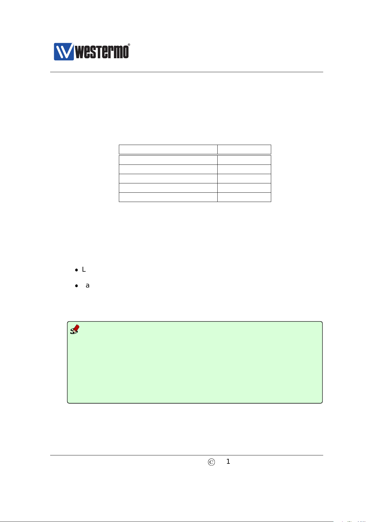
The default IP setting for the switch is as shown in table 2.1.
Address Netmask Gateway
Primary IP address Dynamic (DHCP) (Dynamic) (Dynamic)
Secondary IP address 192.168.2.200 255.255.255.0 Disabled
Table 2.1: Factory Default IP settings.
Thus, when you power up your WeOS unit with the factory configuration, you can
connect to it via two addresses:
The static IP address 192.168.2.200: This address is simplest to use if you
are setting up a single unit.
A dynamic address assigned by a DHCP server3(if present): This address
may be simplest to use if you want to connect and configure multiple new
WeOS units simultaneously.
Note
Before you put your switch into your production network you should change
its IP setting according to your network topology. How you change your IP
setting is described in the next section.
2.2 Modifying the IP Setting
The switch can be configured with a static IP setting, or it can get its IP address
dynamically via DHCP. The latter case is useful if you are running a DHCP server
on the same LAN as the switch will be located.
WeOS provides several management tools, which will be presented further in
later chapters of this guide. In this chapter we limit the scope to describe how
these tools can be used to update the IP settings of the switch.
3
In addition, the unit will autoconfigure itself with a link-local address in the 169.254.x.x range,
where ’x’ is in interval 0-255. See section 19.2.6 for more information.
16
©
2015 Westermo Teleindustri AB
Page 17

Westermo OS Management Guide
Version 4.17.0-0
WeConfig: is Westermo’s Network configuration management tool (NCM)
made for commissioning and maintenance of components in a network. It
replaces the former Westermo tool known as IPConfig. For further information on WeConfig’s features and how to use the tool, see the WeConfig User
Guide[54].
Web: Configuration of IP settings via the Web interface is described in sec-
tion 2.2.1.
CLI: Configuration of IP settings via the Command Line Interface (CLI) is
described in section 2.2.2.
Hint
If you are not sure what IP address your switch has, use the WeConfig tool,
or the CLI via console method (section 2.2.2.1). If neither of these methods
work, please visit section 7.1.3 for information on how to conduct a factory
reset.
©
2015 Westermo Teleindustri AB 17
Page 18
Westermo OS Management Guide
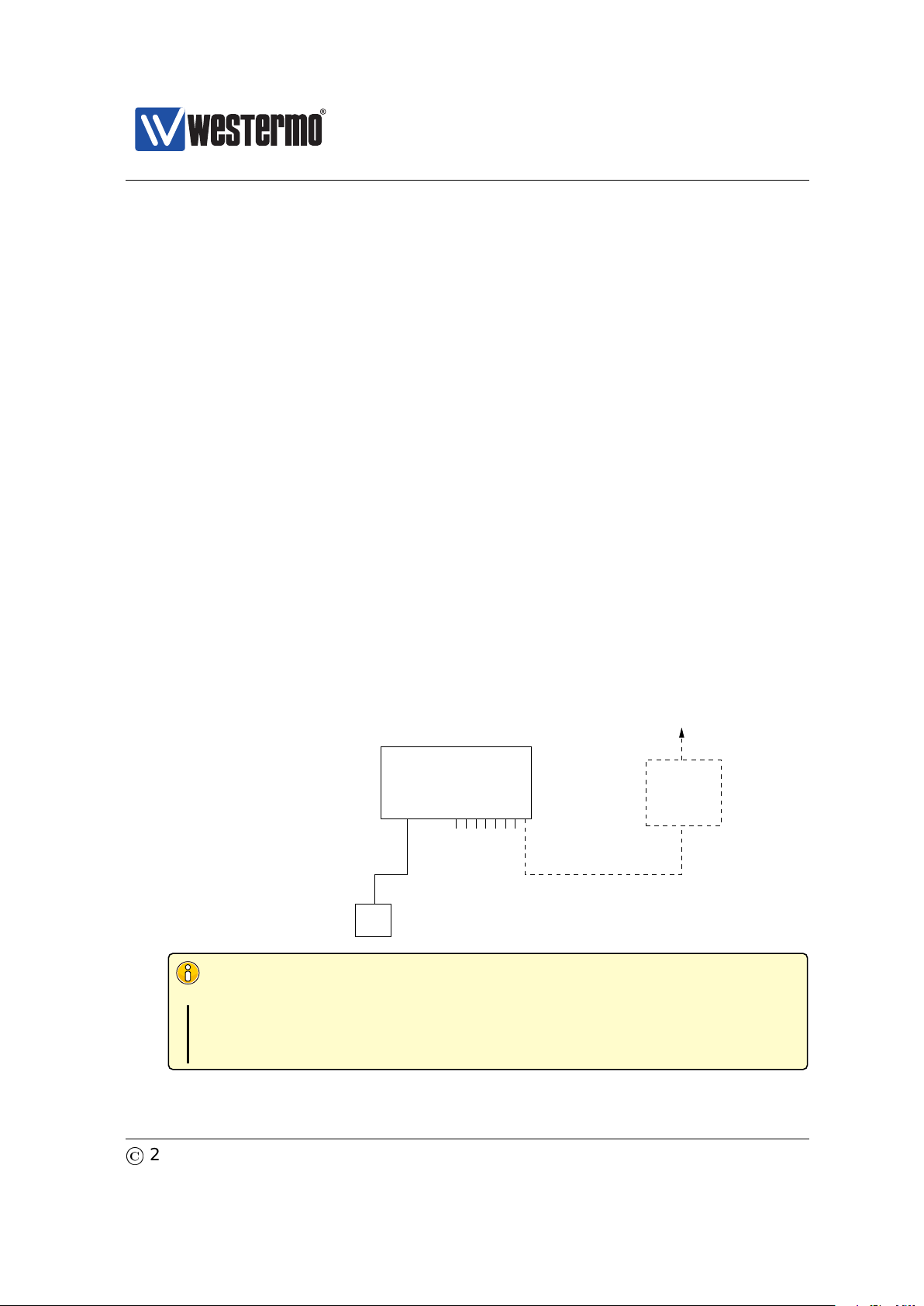
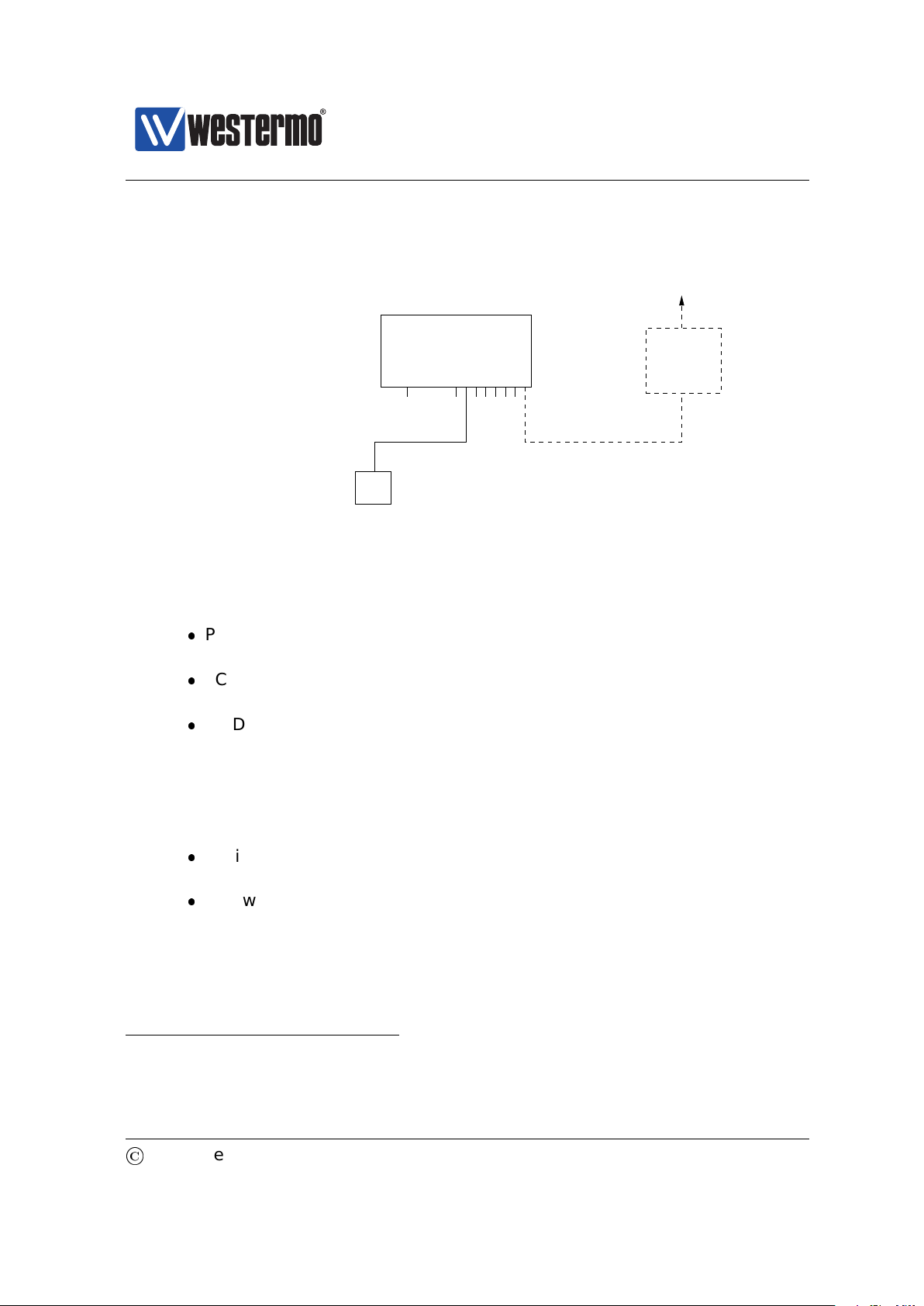
Router IP address:
192.168.55.1
PC
Host with Web browser.
PC IP address and netmask known, e.g.,
IP address 192.168.55.35 and netmask 255.255.255.0
To Internet or
company Intranet
Router
Ethernet portsConsole
Switch with default IP setting:
Default gateway: Disabled
IP address: 192.168.2.200
Netmask: 255.255.255.0
Should get the following settings:
IP address: 192.168.55.100
Netmask: 255.255.255.0
Default gateway: 192.168.55.1
WeOS switch
Version 4.17.0-0
2.2.1 Using the Web Interface to Update the Switch IP Settings
To configure the IP settings via web your switch is required to be located on the
same IP subnet as your PC.
In this example the switch shall be assigned the IP address 192.168.55.100, netmask 255.255.255.0 and default gateway 192.168.55.1. To achieve this you must
(temporarily) change the IP address of the PC in order to be able to communicate
with the switch.
The steps to configure the IP settings via the web interface are as follows:
1. Connect your PC to the switch: Connect your PC to the switch as shown in
the figure above.
2. Modifying IP Settings on PC: The IP settings on the PC must be updated to
match the default settings on the switch, i.e., the PC should be assigned an
IP address on the 192.168.2.0/24 network, e.g.,
PC IP address: 192.168.2.1
PC Netmask: 255.255.255.0
3. Access switch via web browser: Open your web browser and enter URL
http://192.168.2.200 in the browser’s address field. You will be asked to
enter a username and a password. Use the factory default account settings
shown below:
Login username: admin
18
Password: westermo
©
2015 Westermo Teleindustri AB
Page 19
Westermo OS Management Guide
Version 4.17.0-0
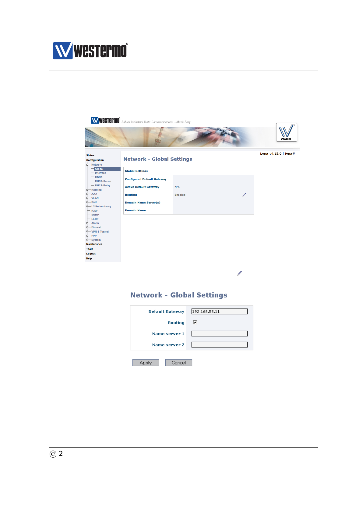
4. Open the Network configuration page: Click on the Configuration topmenu and then on the Network sub-menu and then the Global settings
menu.
5. Configure Default Gateway: Now click the edit icon ( ) in the Global Settings
frame. The following page should appear.
Fill in the appropriate address in the Default Gateway field. In this example,
the default gateway is 192.168.55.1. Click the Apply button. Your switch is
configured with a new default gateway.
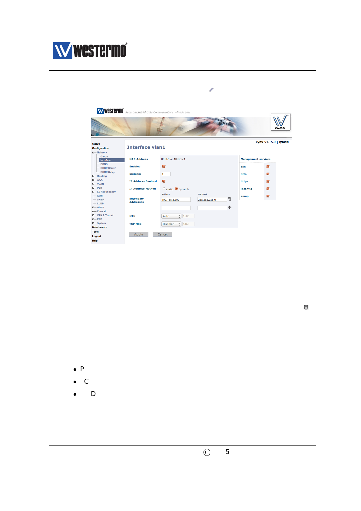
6. Open Interface Configuration Page: Click on the Configuration top-menu
and then on the Network sub-menu and then the Interface sub menu. In
©
2015 Westermo Teleindustri AB 19
Page 20
Westermo OS Management Guide
Version 4.17.0-0
the Interface page, click the edit icon ( ) on the row for the interface
named vlan1. The Interface Configuration Page will appear:
7. Configure Interface IP Settings: Enter the appropriate IP settings for your
switch. In this example we would:
(a) Set IP Address Method to static (radio button).
(b) Set Primary Address to 192.168.55.100 with 255.255.255.0 in the
Netmask field.
(c) Remove Secondary Address (192.168.2.200) using the trash icon ( ).
Click the Apply button and your switch is configured with a new IP address.
8. Reconfigure PC’s IP Settings: As the IP address is changed on the switch,
you cannot reach it from your PC any longer. To access the switch from the
PC, the PC’s IP settings must be changed again. In this case, we assume it
is changed back to its original settings:
PC IP address: 192.168.55.35
PC Netmask: 255.255.255.0
PC Default Gateway: 192.168.55.1
Further management of the switch can be performed via any of the available
management tools - WeConfig, Web, SSH/Telnet/CLI or SNMP.
20
©
2015 Westermo Teleindustri AB
Page 21
Westermo OS Management Guide
Router IP address:
192.168.55.1
PC
Host with terminal emulation program.
PC IP address and netmask known, e.g.,
IP address 192.168.55.35 and netmask 255.255.255.0
To Internet or
company Intranet
Router
Ethernet portsConsole
Switch with default IP setting:
Default gateway: Disabled
IP address: 192.168.2.200
Netmask: 255.255.255.0
Should get the following settings:
IP address: 192.168.55.100
Netmask: 255.255.255.0
Default gateway: 192.168.55.1
WeOS switch
Version 4.17.0-0
2.2.2 Using the CLI to Update the Switch IP Settings
The CLI can be accessed in three ways: via the console port (given that the switch
is equipped with a console port) or via the Ethernet ports using the Secure Shell
(SSH) or the Telnet protocol. Section 2.2.2.1 explains how to access the CLI via
the console port, and how to update the IP settings. Section 2.2.2.2 explains how
to access the CLI via SSH.
Access with Telnet is also possible, but this is not enabled by default on the
switch, and to use it you will first have to access it with one of the other methods
and enable this protocol for management. See Section 7.3.49 (CLI) for information on how to enable the Telnet service on the unit, and then Section 19.4 (Web)
or Section 19.6.6 for information on how to enable Telnet configuration via interface ”vlan1”.
2.2.2.1 Accessing the CLI via the console port
For WeOS switches equipped with a console port, this port can be used to change
IP address of the switch.
1. Connect your PC to the switch: Connect your PC to the switch as shown in
©
2015 Westermo Teleindustri AB 21
the figure below.
Important notice for WeOS Switches equipped with a console port
See the User Guide of your specific product (section 1.5) for information
on what Diagnostic Cable to use when connecting to the console port
of your specific product.
Page 22
Westermo OS Management Guide
Version 4.17.0-0
2. Terminal program: To communicate with the switch via the console port, you
need to use a terminal emulation program on your PC, such as Hypertermi-
nal. Ask your system administrator if you need help to install or configure
your terminal emulation program.
The following settings should be used when connecting to the console port:
Console Port Parameter Setting
Data rate 115200 bits/s
Data bits 8
Stop bits 1
Parity Off
Flow control Off
3. Activating the console: When the switch has finished booting, you will be
asked to press the Enter key on your keyboard to activate the console.
4. Logging in: Now you will be asked to enter a username and thereafter a
password. For a switch using the factory default settings, use the following
login username and password:
Login username: admin
Password: westermo
Below you see a sample printout when logging in on a WeOS switch. (The
password is not ”echoed” back to the screen.)
Example
example login: admin
Password:
.--.--.--.-----.-----.------.-----.-.--.--------.-----.
| | | | -__|__--|
\__/\__/|
Robust Industrial Data Communications -- Made Easy
\\/ Westermo WeOS v4.15.0 4.15.0 -- Jun 16 19:10 CEST 2014
Type: ’help’ for help with commands, ’exit’ to logout or leave a context.
example:/#>
_____._____
_ _
| |__| |
| -__|_| . . |
_____|__
| |__|__|__|
_
| http://www.westermo.com
_____
| info@westermo.se
5. Listing IP address: Use the CLI command ”show iface” to list information
about network interfaces.
22
©
2015 Westermo Teleindustri AB
Page 23

Westermo OS Management Guide
Version 4.17.0-0
Example
example:/#> show iface
Press Ctrl-C or Q(uit) to quit viewer, Space for next page, <CR> for next line.
Interface Name Oper Address/Length MTU MAC/PtP Address
---------------- ---- ------------------ ----- --------------------------lo UP 127.0.0.1/8 16436 N/A
vlan1 UP 192.168.2.200/24 1500 00:07:7c:10:de:e1
------------------------------------------------------------------------------
example:/#>
6. Changing IP address and netmask: To change the switch IP addressing mode
(”static” instead of ”DHCP”), set a static address and netmask, and to skip
secondary addresses, use CLI commands ”configure”, ”iface vlan1”,
”inet static”, ”address <IPV4ADDRESS/LEN>”, ”no address secondary”
and ”end” as shown below. This example is based on the setup in step 1,
and configures the switch with an address (192.168.55.100/24) on the same
IP subnet as the PC.
169.254.145.230/16
Example
example:/#> configure
example:/config/#> iface vlan1
example:/config/iface-vlan1/#> inet static
example:/config/iface-vlan1/#> address 192.168.55.100/24
example:/config/iface-vlan1/#> no address secondary
Remove all secondary IP addresses, are you sure (y/N)? y
Removing all secondary IPs!
example:/config/iface-vlan1/#> end
example:/config/#> end
Stopping DHCP Clients ...................................... [ OK ]
Configuration activated. Remember "copy run start" to save to flash (NVRAM).
example:/#> show iface
Press Ctrl-C or Q(uit) to quit viewer, Space for next page, <CR> for next line.
Interface Name Oper Address/Length MTU MAC/PtP Address
---------------- ---- ------------------ ----- --------------------------lo UP 127.0.0.1/8 16436 N/A
vlan1 UP 192.168.55.100/24 1500 00:07:7c:10:de:e1
------------------------------------------------------------------------------
example:/#>
7. Set default gateway IP address: The figure below shows the same network
setup, but with a router attached to the IP subnet.
With this setup you would like to configure a default gateway IP address
to allow management of the switch from outside the local network. This
©
2015 Westermo Teleindustri AB 23
Page 24
Westermo OS Management Guide
Version 4.17.0-0
can be achieved using CLI commands ”configure”, ”ip”, ”route default
192.168.55.1 <IPADDRESS>”, and ”end” as shown below.
Example
example:/#> configure
example:/config/#> ip
example:/config/ip/#> route default 192.168.55.1
example:/config/ip/#> end
example:/config/#> end
Configuration activated. Remember "copy run start" to save to flash (NVRAM).
example:/#>
8. Save configuration: Although the configuration changes has been activated,
the running configuration must be stored to the startup configuration. Otherwise the changes will be lost if the switch is rebooted.
Example
example:/#> copy running-config startup-config
example:/#>
9. You are now done setting the IP address, subnet mask and default gateway
of your switch. Logout from the CLI using the ”logout” command.
Further management of the switch can be performed via any of the available
management tools - WeConfig, Web, SSH/Telnet/CLI or SNMP.
2.2.2.2 Accessing the CLI via SSH
Configuring the IP settings via SSH/CLI is very similar to configuring them via the
console port. The major differences are:
The IP address of the PC must (temporarily) be changed in order to be able
to communicate with the switch, i.e., the PC should have an address on
network 192.168.2.0/24, e.g., 192.168.2.1/24.
After the IP settings have been changed on the switch, the PC is likely to
loose contact with the switch. The PC must therefore change its IP address
again, and login to the switch again in order to copy the running configuration to the startup configuration.
The steps to configure the IP settings via SSH/CLI are as follows:
1. Connect your PC to the switch: Connect your PC to the switch as shown in
the figure below. In this example we assume the switch will get IP address
24
©
2015 Westermo Teleindustri AB
Page 25
Westermo OS Management Guide
Router IP address:
192.168.55.1
PC
Host with SSHv2 client.
PC IP address and netmask known, e.g.,
IP address 192.168.55.35 and netmask 255.255.255.0
To Internet or
company Intranet
Router
Ethernet portsConsole
Switch with default IP setting:
Default gateway: Disabled
IP address: 192.168.2.200
Netmask: 255.255.255.0
Should get the following settings:
IP address: 192.168.55.100
Netmask: 255.255.255.0
Default gateway: 192.168.55.1
WeOS switch
Version 4.17.0-0
192.168.55.100, netmask 255.255.255.0 and default gateway 192.168.55.1.
2. Modifying IP Settings on PC: The IP settings on the PC must be updated to
match the default settings on the switch, i.e., the PC should be assigned an
IP address on the 192.168.2.0/24 network, e.g.,
3. Connecting and Logging in: When connecting via SSH you will be asked to
4
OpenSSH, http://www.openssh.com
5
Putty, http://www.chiark.greenend.org.uk/~sgtatham/putty/
©
2015 Westermo Teleindustri AB 25
PC IP address: 192.168.2.1
PC Netmask: 255.255.255.0
PC Default Gateway: Not needed
enter a username and thereafter a password. For a switch using the factory
default settings, use the following login username and password:
Login username: admin
Password: westermo
The procedure to connect may vary slightly depending on what SSH client
you are using. The example below show the connection procedure using
Unix OpenSSH4. (On Windows one can use Putty5.)
Page 26

Westermo OS Management Guide
Version 4.17.0-0
Example
user@pc:~$ ssh admin@192.168.2.200
The authenticity of host ’192.168.2.200 (192.168.2.200)’ can’t be established.
RSA key fingerprint is 6d:0c:f3:d3:28:d6:d8:43:bc:69:f8:d0:d6:a2:27:87.
Are you sure you want to continue connecting (yes/no)? yes
Warning: Permanently added ’192.168.2.200’ (RSA) to the list of known hosts.
admin@192.168.2.200’s password:
.--.--.--.-----.-----.------.-----.-.--.--------.-----.
| | | | -__|__--|
\__/\__/|
Robust Industrial Data Communications -- Made Easy
\\/ Westermo WeOS v4.15.0 4.15.0 -- Jun 16 19:10 CEST 2014
Type: ’help’ for help with commands, ’exit’ to logout or leave a context.
example:/#>
_____._____
4. Changing IP settings: The switch IP settings are changed with the same
commands as described when accessing the CLI via the console port (sec-
tion 2.2.2.1). In this example we assign IP address, netmask and default
gateway.
_ _
| |__| |
| -__|_| . . |
_____|__
| |__|__|__|
_
| http://www.westermo.com
_____
| info@westermo.se
Example
example:/#> configure
example:/config/#> iface vlan1
example:/config/iface-vlan1/#> inet static
example:/config/iface-vlan1/#> address 192.168.55.100/24
example:/config/iface-vlan1/#> no address secondary
Remove all secondary IP addresses, are you sure (y/N)? y
Removing all secondary IPs!
example:/config/iface-vlan1/#> end
example:/config/#> ip
example:/config/ip/#> route default 192.168.55.1
example:/config/ip/#> end
example:/config/#> end
The configuration is now changed, but not yet saved to the startup configuration. However, as the IP address is changed, the SSH connection will be
broken.
5. Logging in again to save configuration: To login again, the PC’s IP settings
must be changed again. In this case, we assume it is changed back to its
original settings:
PC IP address: 192.168.55.35
PC Netmask: 255.255.255.0
PC Default Gateway: 192.168.55.1
26
©
2015 Westermo Teleindustri AB
Page 27

Westermo OS Management Guide
Version 4.17.0-0
We can then login again to copy the running configuration to startup configuration.
Example
user@pc:~$ ssh admin@192.168.55.100
The authenticity of host ’192.168.55.100 (192.168.55.100)’ can’t be established.
RSA key fingerprint is 6d:0c:f3:d3:28:d6:d8:43:bc:69:f8:d0:d6:a2:27:87.
Are you sure you want to continue connecting (yes/no)? yes
Warning: Permanently added ’192.168.55.100’ (RSA) to the list of known hosts.
admin@192.168.55.100’s password:
.--.--.--.-----.-----.------.-----.-.--.--------.-----.
| | | | -__|__--|
\__/\__/|
Robust Industrial Data Communications -- Made Easy
\\/ Westermo WeOS v4.15.0 4.15.0 -- Jun 16 19:10 CEST 2014
Type: ’help’ for help with commands, ’exit’ to logout or leave a context.
example:/#> copy running-config startup-config
example:/#>
_____._____
You are now done setting the IP address, subnet mask and default gateway
of your switch. Logout from the CLI using the ”logout” command.
_ _
| |__| |
| -__|_| . . |
_____|__
| |__|__|__|
_
| http://www.westermo.com
_____
| info@westermo.se
Further management of the switch can be performed via any of the available
management tools - WeConfig, Web, SSH/CLI or SNMP.
©
2015 Westermo Teleindustri AB 27
Page 28

Westermo OS Management Guide
Version 4.17.0-0
Chapter 3
Overview of Management Methods
WeOS is managed and monitored using the following tools and interfaces:
WeConfig: is Westermo’s Network configuration management tool (NCM)
made for commissioning and maintenance of components in a network. It
replaces the former Westermo tool known as IPConfig. For further information on WeConfig’s features and how to use the tool, see the WeConfig User
Guide[54].
Web: The WeOS Web interface provides management of essential features.
The Web interface should satisfy the needs of all common use cases.
CLI: The WeOS Command Line Interface is an industry standard CLI, and
provides the most complete management support. The CLI is intended for
advanced users requiring fine grain control of the system.
In addition, WeOS provides device management via SNMP (v1/v2c/v3). A set of
standard MIBs and the WeOS private MIB are supported, as described in chap-
ter 6.
28
©
2015 Westermo Teleindustri AB
Page 29

Westermo OS Management Guide
Version 4.17.0-0
Task WeConfig Web CLI SNMP
Discover WeOS Devices X (X) (X)
Set Device IP Address X X X X
Upgrade firmware X X X
Common management tasks X X X
All management tasks X
Secure management X X X
In the following sections the properties of the WeConfig tool, the Web Interface,
and the CLI are presented further. These sections give information about what
management tool to use for a specific need. For more information on SNMP we
refer to chapter 6.
3.1 When to use the WeConfig tool
The Westermo configuration management tool, WeConfig, is used for basic configuration and maintenance of WeOS products. It is an ideal tool to upgrade
firmware and manage configuration files (backup and restore) of a large set of
WeOS devices. With WeConfig you to scan, discover and draw maps of the WeOS
devices in your network, and you can also conduct some basic configuration of
WeOS units, such as setting the IP address and the default gateway.
For further information on WeConfig’s features and how to use the tool, see the
WeConfig User Guide[54].
3.2 When to use the Web Interface
The Web interface would be the management interface of choice for most users.
The main advantages of the Web Interface are:
Easy to use: The Web management interface provides an easy to use method
to manage the switch.
All common features: The web interface includes support for all essential
management features, and should therefore meet the needs of most users.
Secure management: The web interface can be accessed via regular HTTP
and secure HTTP (HTTPS). Secure management is also possible via the CLI
(SSHv2) and and SNMP (SNMPv3).
©
2015 Westermo Teleindustri AB 29
Page 30
Westermo OS Management Guide
Version 4.17.0-0
Discover other Westermo Switches: The Web contains a discovery service
(IPconfig) similar to what WeConfig provides. (Note, you must still be able
to login to one switch in order to make use of this service.)
To use the Web interface, you must know the IP address of your switch. To find
out the switch IP address you may need to use the WeConfig tool1, but once you
know it you can do the rest of the management via the Web interface.
The Web interface is introduced in chapter 4.
3.3 When to use the Command Line Interface (CLI)
The WeOS CLI aims to serve advanced users. Furthermore, the CLI is the only
management tool which cannot be disabled.
Below we list the situations where the CLI is the most suitable management tool.
Complete set of management features: The CLI includes all the management features available on the switch. If you cannot accomplish your task
with any of the other management tools, the CLI may provide the feature
you need.
Discover other Westermo Switches: The CLI contains a discovery service
similar to what WeConfig provides, but more rudimentary.
Note
You must still be able to login to one switch in order to make use of this
service.
Secure management: To access the CLI you must either have physical access to the switch (console port), or use the Secure Shell (SSHv2) application
to access the CLI remotely. Secure management is also possible via the Web
interface (HTTPS) and SNMP (SNMPv3).
Configuration scripting: With a CLI it is possible to develop automatic configuration scripts, e.g., using the Expect automation and testing tool. Expect
extensions exist for many common scripting languages (Ruby, Perl, Tcl).
As with the Web interface, you must know the IP address of your switch before
you can access the CLI remotely via SSH (access via the console port is possible
1
For more information about finding the IP address of your switch we refer to the Getting Started
guide in chapter 2.
30
©
2015 Westermo Teleindustri AB
Page 31

Westermo OS Management Guide
Version 4.17.0-0
without knowing the switch IP address). To find out the switch IP address you may
need to use the WeConfig tool, but once you know it you can do the rest of the
management via SSH/CLI.
The WeOS CLI is introduced in chapter 5.
©
2015 Westermo Teleindustri AB 31
Page 32

Westermo OS Management Guide
Version 4.17.0-0
Chapter 4
Management via Web Interface
WeOS supports device management via web interface. Both HTTP and HTTPS
are supported. The design is optimised for style sheet and JavaScript2capable
web browsers. In addition, the design allows users to access the web interface
and all settings without a style sheet and JavaScript capable browser, but then
with less guidance and support from the user interface.
When using the Web Management Tool you have to be aware of the following:
Only one user can be logged in at a time (see section 4.2 for more information).
You are automatically logged out after ten (10) minutes of inactivity (see
section 4.2 for more information).
When you click Apply on a page, the settings on that page are immediately
activated.
When you click Apply on a page, all settings are stored in the startup configuration and therefore survive a reboot (see chapter 7 for more information).
Section 4.2 explains how to access the Web Management Tool and section 4.3
describes the web menu hierarchy. In section 4.3 the system overview web pages
are presented. Other pages and settings are described per topic in chapter 20
and following chapters.
1
1
For HTTPS server authentication, a self-signed certificate is used as of WeOS v4.17.0.
2
JavaScript is a trademark of Oracle Corporation.
32
©
2015 Westermo Teleindustri AB
Page 33

Westermo OS Management Guide
Version 4.17.0-0
4.1 Document Conventions
Specific conventions for the web part of this document.
Button Text Buttons are indicated by use of
bold type-writer style.
Menu path:
Top Item ⇒ Sub Item For each page the menu path to
the page is described with this
syntax. It means: First click the
Top Item menu item and in the
sub-menu revealed, click the Sub
Item menu item. See also sec-
tion 4.3.
Menu path:
Top Item ⇒ Sub Item ⇒ Button Text This is an extension to the Menu
path: Top Item ⇒ Sub Item ver-
sion described above. It tells you
to click a button with the text But-
ton Text on the page navigated to
by Top Item ⇒ Sub Item.
Top Item ⇒ Sub Item ⇒ (ctx) The button may be an icon. In this
case the icon is shown. Addition-
ally in parenthesis a sub-context
(ctx) may be described which will
identify a context on the page,
normally identified by its header.
©
2015 Westermo Teleindustri AB 33
Page 34

Westermo OS Management Guide
Version 4.17.0-0
4.2 Logging in
To access the switch through the web interface, enter the appropriate URL (e.g.,
the factory default IP-address http://192.168.2.200) in the address field of your
web-browser. You will then be presented to the login page where you fill in the
username and password, see figure 4.1.
Figure 4.1: Web login window
Currently there is only a single user account defined, the administrator user account. Note that it is the same user account used for login in CLI. Factory default
user account and password are as follows :
Login: admin
Password: westermo
Your web session will last for ten (10) minutes after your latest ”web action”.
Clicking a link or button at least every 10 minutes will let you keep the session
34
©
2015 Westermo Teleindustri AB
Page 35

Westermo OS Management Guide
Version 4.17.0-0
forever. The same goes for pages with an automatic refresh option, given that a
refresh interval of 10 minutes or shorter is selected.
Only one user at a time can be logged into the switch Web Management Tool. If a
new user tries to log in the currently logged in user will automatically be logged
out.
©
2015 Westermo Teleindustri AB 35
Page 36

Westermo OS Management Guide
Version 4.17.0-0
4.3 Navigation
After logging in you will be redirected to the start page, see fig. 4.2. In the page
header you find the menus used to navigate between different tasks. The menu
consists of two rows, the top-menu row, and the sub-menu. For some items you
will be presented to a third level sub-menu below the second level sub-menu. Its
function is analogously to the second level sub-menu .
To navigate in the menu, click on the top-menu to reveal the associated sub-
menu. Then click on the desired sub-menu item. For example, fig. 4.2 shows the
selection of top-menu Status and sub-menu Summary (i.e., Status ⇒ Summary).
Figure 4.2: Unit Summary - the first page after logging in.
The top-level menu structure is described below:
Status - This is where you find status information of the running system (port
status, protocol status, etc.)
Configuration - This is where you configure the unit
Maintenance - This is where you do firmware upgrades, configuration file
backups, view log files, manage port monitoring, etc.
36
©
2015 Westermo Teleindustri AB
Page 37

Westermo OS Management Guide
Version 4.17.0-0
Tools - Here you find various tools for trouble-shooting and other purposes
(e.g., ”ping”).
Pages where you can change settings generally contains an Apply and a Cancel
button, as shown in fig. 4.3. The semantics of the Apply and Cancel buttons are
provided below:
Apply Applies the changes on the current page. Changes are applied
immediately (i.e., no reboot needed), and are also stored in
the startup configuration.
Cancel Discards changes and either returns to an overview page for
the context, or reloads current page and thus shows the current settings.
Figure 4.3: Sample web page containing Apply and Cancel buttons.
Pages with lists of ports may have additional information to display, e.g. if the
port is included in a port aggregate or bonded with PAF. This is indicated by
the background behind the port label is highlighted as shown in fig. 4.4. When
hovering a highlighted port the additional information is displayed in a pop-up.
Inside a drop-down menu, the ports are also highlighted, but no pop-ups are
presented.
©
2015 Westermo Teleindustri AB 37
Page 38

Westermo OS Management Guide
Version 4.17.0-0
38
Figure 4.4: Sample web page with port information pop-up.
©
2015 Westermo Teleindustri AB
Page 39

Westermo OS Management Guide
Version 4.17.0-0
4.4 System Overview
There are two levels of system information, summary and detailed.
4.4.1 System Overview - Summary
Menu path: Status ⇒ Summary
Fig. 4.5 shows the first page you will be presented to after logging into the switch.
It provides a quick overview of the system, including a list of current alarms.
Figure 4.5: The basic system overview page.
Hostname An arbitrary name to identify this unit.
Location An arbitrary description to identify where the unit is
located.
ADSL/VDSL Status Current ADSL/VDSL connection status. Displays ne-
gotiation status, IP-address, up/down speed and DSL
uptime.
Continued on next page
©
2015 Westermo Teleindustri AB 39
Page 40

Westermo OS Management Guide
Version 4.17.0-0
Continued from previous page
Uptime The time passed since last reboot of the unit.
Date The current date and time. System time is config-
ured manually or set by using a NTP-server.
Running Services A list of services currently running on the unit.
Alarms Currently active port and FRNT alarms.
Link alarms are only shown for ports where link
alarm is enabled and when the link is down. FRNT
alarms are only shown for FRNT ports with link down.
Interfaces Displays the interfaces and their primary addresses.
40
©
2015 Westermo Teleindustri AB
Page 41

Westermo OS Management Guide
Version 4.17.0-0
4.4.2 System Overview - Detailed
Menu path: Status ⇒ System
To get more information about the switch you go to the detailed page shown in
fig. 4.6. This page contains more information on hardware (e.g. versions, article
number, etc.) and system status (e.g. memory usage and CPU load).
Hostname An arbitrary name to identify this unit.
Location An arbitrary description to identify unit location.
Contact An arbitrary description to identify a contact per-
son who has more information about management
of the unit and the network.
Uptime The time passed since last reboot of the unit.
Base MAC Address The base MAC address defines the starting point of
the MAC address range used within the unit. This is
a unique number assigned to each unit.
System Default
Gateway Address
Article Number The article number for the unit.
Main Firmware
Version
Build Details The build string of the currently running firmware.
Backup Firmware
Version
Main FPGA Version The version number of the FPGA software.
Boot Loader Version The version number of the boot loader software.
Serial Number The units serial number.
Product The product name.
Model The product model.
Type Description for the card in the specified slot.
Article No. The article number of the card in the specified slot.
Batch ID The batch identification of the card in the specified
Revision The revision of the card in the specified slot.
Enabled Redun-
dancy Protocol(s)
VLANs With IGMP A list of VLANs on which IGMP is enabled.
The operational default gateway for all VLANs on the
unit. Either retrieved dynamically or set statically.
The version number of the main firmware.
The version number of the backup firmware.
slot.
A list of the redundancy protocols currently enabled
on the unit.
Continued on next page
©
2015 Westermo Teleindustri AB 41
Page 42

Westermo OS Management Guide
Version 4.17.0-0
Continued from previous page
SNMP Shows if SNMP support is enable or disabled.
Alarms Currently active port and FRNT alarms.
Link alarms are only shown for ports where link
alarm is enabled and link is down.FRNT alarms are
only shown for FRNT ports where link alarm is enabled and when the link is down.
42
©
2015 Westermo Teleindustri AB
Page 43

Westermo OS Management Guide
Version 4.17.0-0
Figure 4.6: Detailed system overview page.
©
2015 Westermo Teleindustri AB 43
Page 44

Westermo OS Management Guide
Version 4.17.0-0
4.4.3 System Environment
Menu path: Status ⇒ Environment
To get more information about the system environment variables you go to the
environment page.
Temperature Shows system temperature i Celsius(C).
Load
Average
Memory
Usage (%)
DDM/DOM
SFPs
The load average is a standard Linux way of measuring system
load.
A snapshot of RAM (Random Access Memory) usage as percentage of total RAM.
1
Shows DDM/DOM diagnostics for each SFP.
The black bar for each graph represents the first value which
was read after boot up, and the blue bar is current value. The
DDM/DOM information will be polled for each SFP every twelfth
hour. Each graph will then be updated and can consist of up to
20 polled entries. By positioning the mouse over a graph, the
user will be presented with startup, max and min value. Please
note that each graph shows trend over time and not the absolute value, graphs for different SFP should not be compared.
1
DDM/DOM diagnostic information is only available for Westermo DDM SFPs, see the SFP
Transceiver Datasheet of your WeOS product (www.westermo.com).
44
©
2015 Westermo Teleindustri AB
Page 45

Westermo OS Management Guide
Version 4.17.0-0
Chapter 5
Management via Command
Line Interface (CLI)
This chapter introduces the command line interface (CLI) tool. Switches running
WeOS include a CLI similar to what is provided by other major vendors of network
equipment. The CLI provides a more complete set of management features than
the Web interface, the WeConfig tool or SNMP. Thus, when advanced management operations are required, the CLI is the management interface of choice.
The CLI can be accessed via the console port, or remotely via secure shell (SSHv2)
and Telnet1.
Section 5.1 introduces the CLI hierarchy and its various contexts. Section 5.2
explains how to access the CLI interface, and section 5.3 provides general information on how to use the CLI.
The last section (section 5.4) presents CLI commands available in all CLI contexts as well as their syntax. Other CLI commands are described per topic in the
chapters to follow.
5.1 Overview of the WeOS CLI hierarchy
The WeOS CLI is organised in a hierarchical structure. For management purposes,
the use of a hierarchical structure limits the available commands to those relevant for a certain topic. This in turn simplifies switch operation.
1
Telnet server is by default disabled, see also section 7.3.49.
©
2015 Westermo Teleindustri AB 45
Page 46

Westermo OS Management Guide
Global Configuration Context
Administrator Execution Context
Specific Execution Contexts
(RMON, Debug, ...)
Specific Configuration Contexts
Version 4.17.0-0
Figure 5.1: CLI hierarchy
Fig. 5.1 shows an overview of the CLI hierarchy. When the user logs in as ”admin”
the user will enter the CLI with ”administrator” privileges in Admin Exec context.
(In addition to the ”admin” user, future versions of WeOS are likely to support a
”guest” account with limited privileges.)
Admin Exec context In Admin Exec context the user can execute a set of gen-
eral monitoring and diagnostic functions, and also manage configuration
files and firmware versions. From Admin Exec context the user can enter a
set of specific execution contexts, e.g., to view RMON statistics.
Global Configuration context From the Admin Exec context the user can enter
the Global Configuration context. In Global Configuration the user can configure device parameters of global significance, such as hostname and loca-
tion of the device. From Global Configuration the user can reach contexts
specific to certain protocols or device entities such as port, vlan, interface,
and FRNT contexts.
A simple example on CLI usage is given below. There you can see how the CLI
prompt changes to match the current context.
Example
example:/#> configure
example:/config/#> vlan 100
example:/config/vlan-100/#> untagged 1,2
example:/config/vlan-100/#> end
example:/config/#> end
example:/#>
46
©
2015 Westermo Teleindustri AB
Page 47

Westermo OS Management Guide
Version 4.17.0-0
5.2 Accessing the command line interface
To login via the console port you need the username and password. Currently
there is only a single user account defined, the administrator user account. Factory default account and password:
Login: admin
Password: westermo
The same account is used for management via CLI and Web (see section 4). To
reset the administrator password to the default setting, see chapter 7.
5.2.1 Accessing CLI via console port
For WeOS switches equipped with a console port, that port can be used to access
the CLI. (For information on which WeOS devices that have a console port, see
section 1.5.1).
Console cable
See the User Guide of your specific product (section 1.5) for information on
what Diagnostic Cable to use when connecting to the console port of your
specific product.
Recommended Terminal Emulation programs:
Win32: PuTTY, http://www.chiark.greenend.org.uk/~sgtatham/putty/
UNIX: There are different terminal emulation programs for different Unix
dialects. On Linux minicom is recommended.
The following console port settings are used:
Data rate 115200 bits/s
Data bits 8
Stop bits 1
Parity None
Flow control None
The example in below shows how to login via the console port using the PuTTY application. Once you have installed and started PuTTY, configure the appropriate
©
2015 Westermo Teleindustri AB 47
Page 48

Westermo OS Management Guide
Version 4.17.0-0
Serial settings.
Hint
In this example, the switch is accessible via the logical port ”COM3”, but
the USB/serial adapter may be mapped to a different COM port on your PC.
Please check ”Ports (COM and LPT)” in the Windows ”Device Manager” to
get information on what COM port to specify.
When the appropriate serial settings have been configured, select the ”Session”
view. Select Serial as Connection type as shown in the figure below.
To start the serial connection, press the Open button. The figure below shows
the console prompt when logging in to the CLI via the console on a unit named
example.
48
©
2015 Westermo Teleindustri AB
Page 49

Westermo OS Management Guide
example login: admin
Password:
.--.--.--.-----.-----.------.-----.-.--.--------.-----.
| | | | -__|__--|
\__/\__/|
Robust Industrial Data Communications -- Made Easy
\\/ Westermo WeOS v4.15.0 4.15.0 -- Jun 16 19:10 CEST 2014
Type: ’help’ for help with commands, ’exit’ to logout or leave a context.
example:/#>
_____._____
_ _
| |__| |
| -__|_| . . |
_____|__
| |__|__|__|
_
| http://www.westermo.com
_____
| info@westermo.se
5.2.2 Accessing the CLI via SSH or Telnet
Version 4.17.0-0
To gain access to the CLI via SSH you need a SSH client, the switch IP address,
and the account information (username and password).
Recommended SSH Clients:
Win32: PuTTY, http://www.chiark.greenend.org.uk/~sgtatham/putty/
UNIX OpenSSH, http://www.openssh.com
The switch IP address can be found using the WeConfig tool, see the WeConfig
User Guide[54] (additional methods are listed in section 7.1.3).
The following example illustrates how to login to the switch using PuTTY from
a Windows based host system as user admin. In this example, the switch is a
WeOS switch with IP address 192.168.2.200 (the factory default IP address). See
section 5.2 for information about user accounts and passwords.
In the PuTTY session view, select SSH as Connection type, and enter the IP address of the switch (here 192.168.2.200).
©
2015 Westermo Teleindustri AB 49
Page 50

Westermo OS Management Guide
Version 4.17.0-0
Click the Open button to start the SSH session. You will be presented to a login
prompt (see below), and enter login admin and the associated password.
example login: admin
Password:
.--.--.--.-----.-----.------.-----.-.--.--------.-----.
| | | | -__|__--|
\__/\__/|
Robust Industrial Data Communications -- Made Easy
\\/ Westermo WeOS v4.15.0 4.15.0 -- Jun 16 19:10 CEST 2014
Type: ’help’ for help with commands, ’exit’ to logout or leave a context.
example:/#>
_____._____
_ _
| |__| |
| -__|_| . . |
_____|__
| |__|__|__|
_
| http://www.westermo.com
_____
| info@westermo.se
The CLI can be accessed remotely by using a Telnet client, in the same way
as using SSH. Of security reasons, use of Telnet is discouraged and therefore
disabled by default. In order to manage the unit via Telnet, you must first:
Enable the Telnet server via the CLI, see section 7.3.49.
Enable telnet management for the desired network interface(s) via the CLI
(see section 19.6.6).
50
©
2015 Westermo Teleindustri AB
Page 51

Westermo OS Management Guide
Version 4.17.0-0
5.3 Using the CLI
5.3.1 Starting out with the CLI
When first entering the CLI you end up in the Admin Exec context. In the Admin
Exec you can view system status information using various ”show” commands,
upgrade system firmware, etc., as well as other functions, which do not affect the
system configuration.
To be able to modify the switch configuration you should enter the Global Con-
figuration context, by using the ”configure” command as shown below. From
the Global Configuration you are able to configure system parameters such as its
”hostname” or its ”date”.
Example
example:/#> configure
example:/config/#>
As described in section 5.3.2 you can reach other, specific configuration contexts
from the Global Configuration context.
Example
example:/#> configure
example:/config/#> vlan 100
example:/config/vlan-100/#> untagged 1/1,1/2
example:/config/vlan-100/#> end
example:/config/#> end
example:/#>
To get help on what commands are available in the current context, use the
”help” command (see example in fig. 5.2). First the context specific configu-
ration commands are shown, followed by the commands to show the current
configuration settings. At the end, commands available in all contexts are shown
(see also section 5.4.).
©
2015 Westermo Teleindustri AB 51
Page 52

Westermo OS Management Guide
Version 4.17.0-0
Example
example:/config/vlan-100/#> help
Available Commands
==============================================================================
enable Enable, or disable this VLAN
name <ARG> Set name of VLAN
tagged <ARG> Set tagged ports
untagged <ARG> Set untagged ports
channel <ARG> Set VLAN channel interface
priority <ARG> Set VLAN priority, overrides port priority
igmp Enable, or disable IGMP Snooping
show enable Show if VLAN is active or not
show name Show name of VLAN
show tagged Show tagged ports
show untagged Show untagged ports
show channel Show VLAN channel interface
show priority Show VLAN priority setting
show igmp Show IGMP Snooping status
no <ARG> Prefix, used to disable services or settings.
do Shortcut to EXEC mode, e.g. do ping <IP>.
end Save settings and return to previous mode.
leave Save settings and return to EXEC mode.
abort Cancel all changes and leave this mode.
show <ARG> Show summary, or status.
repeat <ARG> Repeat next command every second, until Ctrl-C
help <ARG> This help text.
tutorial Brief introduction to the CLI
==============================================================================
<ARG> - Command takes argument(s), see help <command> for further information.
Short forms of commands are possible, see the tutorial for more help.
example:/config/vlan-100/#>
Figure 5.2: Use of the ”help” command to list available commands (here in the
VLAN context).
The ”help” command can also be used to get information on a specific command
as shown below.
Example
example:/config/vlan-100/#> help igmp
Syntax:
Description:
==============================================================================
The [no] keyword is when you want to disable a service or remove a property.
example:/config/vlan-100/#>
52
[no] igmp
Enable, or disable IGMP Snooping
©
2015 Westermo Teleindustri AB
Page 53

Westermo OS Management Guide
Version 4.17.0-0
The CLI supports basic TAB-completion, which can come in handy when you do
not know the exact command name, e.g., writing ”fi[TAB]” within the IP context
will expand to ”firewall”.
TAB-completion is only able to expand the full command when there is no ambiguity. Otherwise the available alternatives will be listed.
Example
example:/#> d[TAB]
do debug date dir delete
example:/#> d
Furthermore, when there is no ambiguity it is possible to use an abbreviation of
a command instead of the full command (i.e., without using TAB-completion).
Example
example:/#> con
example:/config/#>
5.3.2 Entering and leaving CLI contexts
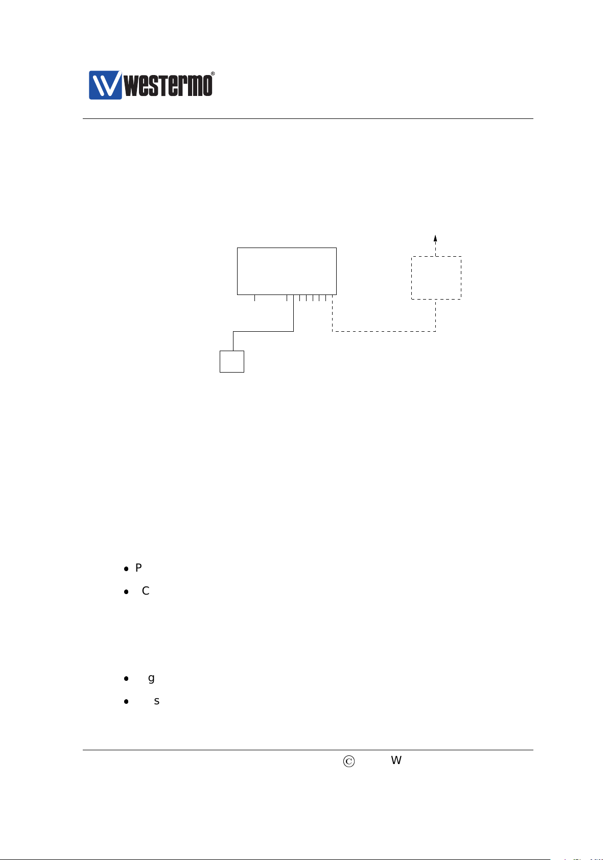
Fig. 5.3 gives a general overview of how to enter and leave the various context
in the CLI hierarchy. The commands to move between contexts are further discussed in the text below.
To enter Global Configuration context from Admin Exec context, the ”configure”
command is used. From Global Configuration context one can reach several specific configuration contexts, and the command to enter them is context specific,
e.g.,:
vlan <VID> Manage VLAN settings for VLAN with given VID.
port <PORT> Manage port settings for port with given PORT identifier.
interface <IFNAME> Manage settings for the given network interface.
By entering the Global Configuration context the user is able to interactively
change the device configuration, however, configuration changes will not take
effect until the user leaves the configuration contexts and returns to the Admin
Exec context via the ”end” or ”leave” commands.
When the user returns to Admin Exec context, the running-configuration of the
switch will be updated. To make the configuration changes permanent the running-
©
2015 Westermo Teleindustri AB 53
Page 54

Westermo OS Management Guide
Context
Port Configuration
endport <...>
monitor end
Context
Port Monitoring
vlan <...> end
General IP
Config. Context
Firewall/NAT
Config. Context
endfirewall
Login prompt (console/SSH)
Administrator Execution Context
Global Configuration Context
logout
leave
username & password end/logout
endconfigure
RMON
Context
endrmon
ip
end
VLAN Configuration
Context
Version 4.17.0-0
Figure 5.3: Moving between CLI contexts. Only a subset of the available contexts
is shown. Although not shown, the leave and logout commands can be used from
all contexts.
configuration should be saved to the startup-configuration using the ”copy” com-
mand, see also chapter 7.
It is also possible to leave the configuration contexts without updating the running-
configuration. The commands to leave a context are listed below. More information on these and other general CLI commands can be found in section 5.4.
end Confirms configuration changes conducted in this context and
returns to the context immediately above. If issued within the
Global Configuration context, the user returns to the Admin
Exec context and the running-configuration is updated.
leave Confirms configuration changes made and returns to Admin
Exec context. The running-configuration is updated.
Ctrl-Z An alias for leave. Ends your configuration session and returns
to Admin Exec context.
Continued on next page
54
©
2015 Westermo Teleindustri AB
Page 55

Westermo OS Management Guide
Version 4.17.0-0
Continued from previous page
abort Discards configuration changes conducted in this context and
returns to the context immediately above. If issued within the
Global Configuration context, the user returns to the Admin
Exec context without updating the running-configuration. If
issued in Admin Exec context it works the same as logout.
exit An alias for abort.
Ctrl-D An alias for abort. Blocked if any text is already input on the
command line.
logout Log out from the CLI. If conducted from within any of the con-
figuration contexts, all configuration changes are discarded
(i.e., the running configuration is not updated).
5.3.3 CLI command conventions
This section describes the CLI command conventions used within this guide. The
syntax for a sample set of CLI commands is shown below:
[no] default-gw <ADDRESS>
igmp-interval <12|30|70|150>
show iface [IFNAMELIST]
Convention Description
command syntax Command syntax is generally written in typewriter
style (fixed width)
”command syntax” Commands described in running text use bold type-
writer style enclosed by quotation marks.
UPPERCASE A variable parameter. Enter value according to the de-
scription that follows.
lowercase A keyword parameter. Enter value according to the
given syntax.
| Vertical bar. Used to separate alternative (mutually ex-
clusive) parameters.
< > Angle brackets. Encloses a mandatory parameter.
[ ] Squared brackets. Encloses an optional parameter.
Continued on next page
©
2015 Westermo Teleindustri AB 55
Page 56

Westermo OS Management Guide
Version 4.17.0-0
Continued from previous page
Convention Description
[< >] Angle brackets within squared brackets. Encloses a
mandatory parameter within an optional choice.
56
©
2015 Westermo Teleindustri AB
Page 57

Westermo OS Management Guide
Version 4.17.0-0
5.4 General CLI commands
The majority of the CLI commands are specific to a certain context, however,
there is a set of CLI commands available in all contexts. These commands are
explained further here. The ”configure” command used to enter the Global
Configuration context from the Admin Exec context, is also covered.
Command Section
no <COMMAND> Section 5.4.1
do Section 5.4.2
end Section 5.4.3
leave Section 5.4.4
abort Section 5.4.5
logout Section 5.4.6
repeat <COMMAND> Section 5.4.7
help [COMMAND] Section 5.4.8
tutorial Section 5.4.9
configure [terminal] Section 5.4.10
5.4.1 Negate/disable a setting
Syntax no <COMMAND>
Context All contexts
Usage Depending on context the ”no” command disables or resets a setting to
default.
Primarily used within configuration contexts to negate or disable a configuration setting, e.g., in port context ”no flow-control” disables flow control. For some commands, ”no” is used to reset to a default value, e.g., ”no
polling-interval” (NTP client context) sets the NTP polling-interval to its
default value (600 seconds).
The ”no” command can also be used to negate/disable certain commands
outside the configuration context, e.g., to disable debugging or port monitoring.
Default values Not applicable
©
2015 Westermo Teleindustri AB 57
Page 58

Westermo OS Management Guide
Version 4.17.0-0
5.4.2 Execute (do) command from Admin Exec context
Syntax do <COMMAND>
Context All contexts
Usage Use the ”do <COMMAND>” to execute a COMMAND available in Admin Exec
context from any context.
For example, when located in Global Configuration context, the user could
run ”do show running-config” to see the running configuration, or run
”do ping 192.168.1.1” to ”ping” IP address 192.168.1.1.
Default values Not applicable
5.4.3 End context
Syntax end
Context All contexts
Usage Leave this context and return to the context immediately above. If this
command is issued within any of the configuration contexts, the command
implies that the configuration changes conducted within that context are
confirmed. If the command is issued in the Global Configuration context,
the user returns to the Admin Exec context, and the running-configuration
is updated.
Default values Not applicable
5.4.4 Leave context
Syntax leave
Context All contexts
Usage Leave this context and return to the Admin Exec context. If this command
is issued within any of the configuration contexts, the command implies
that the configuration changes conducted are confirmed, and the running-
configuration is updated.
Default values Not applicable
58
©
2015 Westermo Teleindustri AB
Page 59

Westermo OS Management Guide
Version 4.17.0-0
5.4.5 Abort context
Syntax abort
Context All contexts
Usage Leave this context and return to the context immediately above. If this
command is issued within any of the configuration contexts, the command
implies that the configuration changes conducted within that context are
discarded. If the command is issued in the Global Configuration context,
the user returns to the Admin Exec context without updating the running-
configuration.
Default values Not applicable
5.4.6 Logout
Syntax logout
Context All contexts
Usage Logout from system. If this command is issued within any of the con-
figuration contexts, the command implies that the configuration changes
conducted are discarded, i.e., the running-configuration is not updated.
Default values Not applicable
5.4.7 Repeat a command
Syntax repeat <COMMAND>
Context Admin Exec context
Usage Repeat COMMAND every second until Ctrl-C is pressed.
Default values Not applicable
5.4.8 On-line help
Syntax help <COMMAND>
Context All contexts
©
2015 Westermo Teleindustri AB 59
Page 60

Westermo OS Management Guide
Version 4.17.0-0
Usage Show help information specific to a certain context, or a specific com-
mand.
Default values If no COMMAND is specified, help information related to the cur-
rent context is shown.
5.4.9 CLI tutorial
Syntax tutorial
Context All contexts
Usage Show CLI tutorial text.
Default values Not applicable
5.4.10 Entering Global Configuration Context
When a user logs in to the CLI the user will enter the Admin Exec context. In
Admin Exec context the user can view status information and have access to
tools such as ping and traceroute, but is not able to perform any configuration.
To configure the device, the user can use the configure command to enter the
Global Configuration context.
Syntax configure [terminal]
Context Admin Exec context
Usage Enter global Configuration Context.
The optional terminal argument is a compatibility keyword, for advanced
users. It disables all safe guards (yes-or-no questions), making it possible to
paste-in configuration files into the terminal.
Pasting in configuration files can also be done with the copy command as
copy con run to copy console to running-config.
Default values Interactive mode (i.e. the ”terminal” argument does not apply
by default)
60
©
2015 Westermo Teleindustri AB
Page 61

Westermo OS Management Guide
Version 4.17.0-0
Chapter 6
WeOS SNMP Support
The Simple Network Management Protocol (SNMP) provides a standardised method
to manage and monitor IP devices remotely. The WeOS SNMP agent supports
SNMP v1, v2c and v3.
6.1 Introduction and feature overview
Table 6.1 shows WeOS SNMP control features for the Web and CLI interfaces.
Further description of the SNMP support is presented in the sections 6.1.1-6.1.6.
If you are only interested in knowing how to manage SNMP features via the Web
or CLI, please visit sections 6.2 or 6.3 directly.
6.1.1 SNMP introduction
The Simple Network Management Protocol (SNMP) provides a standardised method
to manage and monitor IP devices remotely. In SNMP a manager station can manage a set of status and configuration objects via an SNMP agent on the management unit. The WeOS SNMP agent supports SNMP v1, v2c and v3.
An SNMP manager:
can send SNMP GET messages to poll status and configuration information
from an SNMP agent.
©
2015 Westermo Teleindustri AB 61
Page 62

Westermo OS Management Guide
Version 4.17.0-0
Feature Web CLI General
(Sec. 6.2) (Sec. 6.3) Description
General
Enable/disable SNMP X X
SNMPv1/v2c
Read Community X X Sec. 6.1.2
Write Community X X ”
Trap Community X X Sec. 6.1.2-6.1.3
Trap Host X X Sec. 6.1.3
SNMPv3
Read-Only SNMPv3 User X X Sec. 6.1.4
Read/Write SNMPv3 User X X ”
Table 6.1: WeOS control of SNMP features.
can send SNMP SET messages to the SNMP agent to modify the device settings (or issue commands such as ’reboot’).
can get notified by an agent when specific events occur, such as link down
event, via SNMP TRAP messages.
The objects manageable via SNMP are defined in a management information base
(MIB). The WeOS MIB support aims at providing SNMP management primarily via
standard MIBs to enable easy integration with existing SNMP management tools.
In addition, WeOS includes an enterprise MIB (private MIB) to provide access to
MIB objects not available via the standard MIBs.
6.1.2 SNMP Communities
An SNMP community is a relationship between the manager and managed station. It can be seen as a (very) basic authentication and authorisation mechanism
for SNMP v1 and v2c1. Three types of communities are supported:
Read community: The SNMP read community is used by a manager to read
SNMP MIB objects from a managed station.
Default read community: public
1
See section 6.1.4 for secure management using SNMPv3.
62
©
2015 Westermo Teleindustri AB
Page 63

Westermo OS Management Guide
SNMP
Manager
Station
Managed
Device
Agent
SNMP
MIB
Managed
Device
MIB
Agent
SNMP
Internet/Intranet
Version 4.17.0-0
Figure 6.1: Sample SNMP setup, where one manager station controls two devices
by communicating with SNMP agents running on the managed devices.
Write community: The SNMP write community can be used to write (and
read) SNMP MIB objects to (from) a managed station. Thus, if the agent has
its write community enabled, it is possible to configure the switch via SNMP.
The write community is typically named ”private”.
Default write community: Disabled
Trap community: The SNMP trap community is used when an agent wants
to send a notification to the manager (SNMP Trap). The trap community is
typically named ”public”.
Default trap community: trap
Warning
Using the well-known community strings ”public” and ”private” could pose
a serious security problem.
6.1.3 Trap Support
SNMP traps are only generated if there is at least one Trap Host (i.e., SNMP man-
agement station) defined. Up to three Trap Hosts can be defined. If two or more
Trap Hosts are configured, traps will be sent to all of them.
©
2015 Westermo Teleindustri AB 63
Page 64

Westermo OS Management Guide
Version 4.17.0-0
The WeOS SNMP trap support is integrated with the WeOS alarm handling system (see section 24.1). This means that you as an operator have fine-grained
control of which traps to send. All traps in the list below, except Coldstart and
lldpRemTablesChange, can be controlled via the alarm handling system.
Link Alarm: A trap is generated on link up or link down, given that Link Alarm
is enabled on that specific port (see sections 24.1.3 and 8.1.5).
Link Down OID: iso(1).org(3).dod(6).internet(1).snmpV2(6).snmpModules(3).
snmpMIB(1).snmpMIBObjects(1).snmpTraps(5).linkDown(3)
Link Up OID: iso(1).org(3).dod(6).internet(1).snmpV2(6).snmpModules(3).
snmpMIB(1).snmpMIBObjects(1).snmpTraps(5).linkUp(4)
Note
When a port is being reconfigured, link down and link up events are
likely to occur. If link-alarm is enabled on that port, a couple of SNMP
traps are likely to be generated as a side-effect of the port reconfiguration.
Cold Start: A trap is generated when a system comes up.
OID: iso(1).org(3).dod(6).internet(1).snmpV2(6).snmpModules(3).
snmpMIB(1).snmpMIBObjects(1).snmpTraps(5).coldStart(1)
LLDP Remote System Update: A trap is generated when a remote system
has updated.
OID: iso(1).std(0).iso8802(8802).ieee802dot1(1).ieee802dot1mibs(1).
lldpMIB(2).lldpNotifications(0).lldpNotificationPrefix(0).lldpRemTablesChange(1)
Digital-In: A trap is generated when the voltage level on the pins of a
digital-in sensor changes from high to low, or low to high.
Digital-In High OID: iso(1).org(3).dod(6).internet(1).private(4).
enterprises(1).westermo(16177).common(2).weos(1).notifications(6).
sensorNotifications(1).sensorNotificationPrefix(0).digitalInHigh(1)
Digital-In Low OID: iso(1).org(3).dod(6).internet(1).private(4).
enterprises(1).westermo(16177).common(2).weos(1).notifications(6).
sensorNotifications(1).sensorNotificationPrefix(0).digitalInLow(2)
Power Supply: A trap is generated when the voltage level on any of the
power feeds changes from high to low, or low to high.
64
©
2015 Westermo Teleindustri AB
Page 65

Westermo OS Management Guide
Version 4.17.0-0
Power Supply High OID: iso(1).org(3).dod(6).internet(1).private(4).
enterprises(1).westermo(16177).common(2).weos(1).notifications(6).
sensorNotifications(1).sensorNotificationPrefix(0).powerSupplyHigh(3)
Power Supply Low OID: iso(1).org(3).dod(6).internet(1).private(4).
enterprises(1).westermo(16177).common(2).weos(1).notifications(6).
sensorNotifications(1).sensorNotificationPrefix(0).powerSupplyLow(4)
Temperature: A trap is generated when the temperature measured by a
built-in temperature sensor reaches the configured rising or falling thresholds.
Temperature High OID: iso(1).org(3).dod(6).internet(1).private(4).
enterprises(1).westermo(16177).common(2).weos(1).notifications(6).
sensorNotifications(1).sensorNotificationPrefix(0).temperatureHigh(5)
Temperature Low OID: iso(1).org(3).dod(6).internet(1).private(4).
enterprises(1).westermo(16177).common(2).weos(1).notifications(6).
sensorNotifications(1).sensorNotificationPrefix(0).temperatureLow(6)
FRNT Ring Status: A trap is generated when a unit detects a change of
FRNT ring status, i.e., ring up (ring mode) or ring down (bus mode).
FRNT Ring Up OID: iso(1).org(3).dod(6).internet(1).private(4).
enterprises(1).westermo(16177).common(2).weos(1).notifications(6).
frntNotifications(2).frntNotificationPrefix(0).frntRingUp(1)
FRNT Ring Down OID: iso(1).org(3).dod(6).internet(1).private(4).
enterprises(1).westermo(16177).common(2).weos(1).notifications(6).
frntNotifications(2).frntNotificationPrefix(0).frntRingDown(2)
SNR-margin: On units with a SHDSL/xDSL port traps are generated when
the SNR margin falls below (or rises above) a configurable threshold.
OID: iso(1).org(3).dod(6).internet(1).mgmt(2).mib-2(1).transmission(10).
hdsl2ShdslMIB(48).hdsl2ShdslNotifications(0).hdsl2ShdslSNRMarginCrossing(2)
LFF Status: On units with SHDSL ports, a trap is generated when a unit
detects a change in the Link Fault Forward (LFF) status on a SHDSL port, i.e.,
if the remote end reports that its Ethernet port is up or down.
LFF Remote Up OID: iso(1).org(3).dod(6).internet(1).private(4).
enterprises(1).westermo(16177).common(2).weos(1).notifications(6).
lffNotifications(3).lffNotificationPrefix(0).lffRemoteUp(1)
©
2015 Westermo Teleindustri AB 65
Page 66

Westermo OS Management Guide
Version 4.17.0-0
LFF Remote Fail OID: iso(1).org(3).dod(6).internet(1).private(4).
enterprises(1).westermo(16177).common(2).weos(1).notifications(6).
lffNotifications(3).lffNotificationPrefix(0).lffRemoteFail(2)
PoE total power consumption: On units with Ethernet ports supporting
Power over Ethernet, traps are generated with the total consumed power
rises above (or falls below) a configurable threshold.
Power consumption above threshold OID: iso(1).org(3).dod(6).internet(1).
mgmt(2).mib-2(1).powerEthernetMIB(105).pethNotifications(0).
pethMainPowerUsageOnNotification(2)
Power consumption below threshold OID: iso(1).org(3).dod(6).internet(1).
mgmt(2).mib-2(1).powerEthernetMIB(105).pethNotifications(0).
pethMainPowerUsageOffNotification(3)
Summary Alarm Status: The summary alarm status (summaryAlarmSta-
tus) follows the status of the ON LED:
– when the ON LED turns red, the summaryAlarmStatus has value Warn-
ing (1).
– when the ON LED turns green, the summaryAlarmStatus has value OK
(2).
It is possible to get SNMP traps when the summary Alarm Status changes
state (see section 24.3.16 for information of how to enable summary alarm
traps). When enabled, a summaryAlarmOK trap is sent when the ON LED
turns green, and a summaryAlarmWarning trap is sent when it turns red.
Summary Alarm OK OID: iso(1).org(3).dod(6).internet(1).private(4).
enterprises(1).westermo(16177).common(2).weos(1).notifications(6).
genericNotifications(4).genericNotificationPrefix(0).summaryAlarmOK(1)
Summary Alarm Warning OID: iso(1).org(3).dod(6).internet(1).private(4).
enterprises(1).westermo(16177).common(2).weos(1).notifications(6).
genericNotifications(4).genericNotificationPrefix(0).summaryAlarmWarning(2)
The summary alarm status can be read at the following OID:
iso(1).org(3).dod(6).internet(1).private(4).enterprises(1).westermo(16177).
common(2).weos(1).system(5).eventSystem(2).summaryAlarmStatus(1)
66
©
2015 Westermo Teleindustri AB
Page 67

Westermo OS Management Guide
Version 4.17.0-0
6.1.4 Secure management using SNMPv3
To manage a unit securely via SNMP, SNMPv3 should be used. SNMPv3 provides
privacy and integrity (per packet authentication) to the SNMP messages.
SNMPv3 introduces the notion of a SNMPv3 user, as opposed to the community
concept used in SNMPv1/v2c. The following parameters can be configured for an
SNMPv3 user.
Read-Only or Read-Write access: Defines whether the user should have read
access to the SNMP variables, or be able to read and modify them.
Security Mode: Three security modes are available:
– noAuthnoPriv: No security (i.e., neither authentication, nor encryption)
– authNoPriv: Authentication, but no privacy.
– authPriv: Authentication and Encryption
Note
As of WeOS v4.17.0, the WeOS SNMP agent accepts SNMP requests of
security level authNoPriv also for SNMPv3 users created at level auth-
Priv. This feature is likely to be removed in future WeOS releases.
Encryption protocol: WeOS offers SNMPv3 data encryption using DES and
AES-128.
Authentication protocol: WeOS offers SNMPv3 data integrity using using
MD5 and SHA1.
Scope: A user can be restrained to only access a part of the MIB tree supported by the unit.
The encryption and authentication passwords are strings of 8-16 characters.
ASCII characters 33-126 except ’#’ (ASCII 35) are allowed.
A maximum of 8 SNMPv3 users can be defined, each with their own parameter
set.
6.1.4.1 SNMPv3 example
This example illustrates the configuration of an SNMPv3 user on the a WeOS
switch. The user alice is grated read-only access to the full MIB tree. Security
©
2015 Westermo Teleindustri AB 67
Page 68

Westermo OS Management Guide
Version 4.17.0-0
level authNoPriv is used where SHA1 is used as authentication protocol.
Example
example:/#> configure
example:/config/#> snmp-server
example:/config/snmp/#> rouser alice auth sha1 alicepwd
example:/config/snmp/#> leave
example:/#> cp running start
Section 6.1.6 lists recommended SNMP management software. Those tools have
graphical user interfaces and should be straight forward to use. For a simple
test you could also use the (Unix) Net-SNMP ”snmpwalk” command. (Here it
is assumed that the switch is accessible on IP address 192.168.2.200 and the
”walk” is limited to the mib-2 system’s group).
Example
mypc:~$ snmpwalk -v3 -u alice -l authNoPriv -a SHA -A alicepwd 192.168.2.200 system
SNMPv2-MIB::sysDescr.0 = STRING: Westermo RedFox Industrial, primary: v4.4.0, backup: v4.
bootloader: v2.01, fpga: v20080626
SNMPv2-MIB::sysObjectID.0 = OID: SNMPv2-SMI::enterprises.16177
DISMAN-EVENT-MIB::sysUpTimeInstance = Timeticks: (94018) 0:15:40.18
SNMPv2-MIB::sysContact.0 = STRING:
SNMPv2-MIB::sysName.0 = STRING: redfox
SNMPv2-MIB::sysLocation.0 = STRING:
SNMPv2-MIB::sysServices.0 = INTEGER: 79
SNMPv2-MIB::sysORLastChange.0 = Timeticks: (0) 0:00:00.00
mypc:~$
6.1.5 Supported MIBs
6.1.5.1 Standard MIBs
As of WeOS v4.17.0 the following standard MIBs are supported:
RFC1213 MIB-2: The original MIB-2 standard MIB.
RFC2863 Interface MIB: The ifXTable of the IF-MIB is supported.
RFC2819 RMON MIB: RMON Ethernet statistics (etherStatsTable) is supported.
RFC4188 Bridge MIB
RFC4318 RSTP MIB
RFC4363 Q-BRIDGE MIB: The dot1qVlan group and dot1qVlanStaticTable are
supported, enabling support for static VLAN configuration.
68
©
2015 Westermo Teleindustri AB
Page 69

Westermo OS Management Guide
Version 4.17.0-0
RFC4836 MAU MIB: The dot3IfMauBasicGroup and dot3IfMauAutoNegGroup
of the MAU MIB are supported.
RFC3635 Ether-like Interface MIB: The dot3StatsTable is supported, enabling
monitoring of various error counters for Ethernet ports.
RFC4133 Entity MIB: The entityPhysical group of the Entity MIB is supported.
It can be used to read unit serial number, firmware version, etc.
RFC3433 Entity Sensor MIB: The Entity Sensor MIB can be used to monitor
the status of unit sensors for temperature, power supply, and ”digital-in”,
etc.
RFC 4319 HDSL2/SHDSL MIB: On products with SHDSL ports, the
hdsl2ShdslSpanConfTable, hdsl2ShdslSpanStatusTable,
hdsl2ShdslInventoryTable and hdsl2ShdslSpanConfProfileTable are supported
(read-only).
RFC 3621 Power Ethernet MIB: The PoE MIB is supported on products with
PoE ports.
IEEE 802.1AB LLDP MIB
RFC2787 VRRPv2 MIB: The vrrpOperations group is supported (read-only).
RFC6527 VRRPv3 MIB: The vrrpv3Operations group is supported (read-only).
6.1.5.2 Private MIB
To use the WeOS private MIB, two Westermo specific MIB files should be loaded
into your SNMP management software (see section 6.1.6 for information on recommended management software):
WESTERMO-MIB: Defines the top level objects of the Westermo Private MIB
name space.
WESTERMO-WEOS-MIB: Defines the WeOS branch of the Westermo Private
MIB.
6.1.6 Recommended Management Software
The following SNMP managers are recommended:
©
2015 Westermo Teleindustri AB 69
Page 70

OidView from ByteSphere2.
MG-SOFT MIB Browser Pro. from MG-SOFT3.
SNMPc from Castlerock Computing4.
Westermo OS Management Guide
Version 4.17.0-0
2
http://www.oidview.com/oidview.html. OidView is a trademark of BYTESPHERE TECHNOLO-
GIES LLC.
3
http://www.mg-soft.com/mgMibBrowserPE.html.
4
http://www.castlerock.com/. SNMPc is a trademark of Castlerock Computing.
70
©
2015 Westermo Teleindustri AB
Page 71

Westermo OS Management Guide
Version 4.17.0-0
6.2 Managing SNMP via the web interface
Menu path: Configuration ⇒ SNMP
On the SNMP configuration page you will be presented to the current settings for
SNMP on your switch, see below. You may change the settings by editing the
page.
On the lower part of the page there is a list of SNMP v3 Users.
Enabled Check the box to enable SNMP. If you have a
JavaScript enabled browser the other settings
will not be displayed unless you check this box.
Read Community A community identifier for read access. Leave
blank to disable read community.
Write Community A community identifier for read/write access.
Leave blank to disable write community.
Trap Community A community identifier for traps. Defaults to
community identifier trap.
Trap Host Address 1/2/3 IP address of SNMP trap management station.
None, one , two or three addresses may be
filled in. Leave all blank to disable SNMP traps.
©
2015 Westermo Teleindustri AB 71
Page 72

Westermo OS Management Guide
Version 4.17.0-0
6.2.1 Manage SNMP v3 Users
On the lower part of the SNMP configuration page you will be presented to the
list of currently configured SNMP v3 users.
Figure 6.2: Listing of SNMP v3 users.
Type Access rights for the user.
rwuser User has read and write access.
rouser User has read access only.
Name A text string defining the user. Max 32 characters. Valid char-
acters are ASCII 33-126 except ’#’ (ASCII 35).
Auth Achieve message integrity protection by specifying MD5 or
SHA1 message authentication.
Auth.
Passphrase
Crypto Achieve message privacy by specifying DES or AES128 mes-
Crypto
Passphrase
OID Tree Limit access to a certain branch of the supported MIB. Defaults
The authentication password is a string of 8-16 characters.
ASCII characters 33-126 except ’#’ (ASCII 35) are allowed.
sage encryption.
The encryption password is a string of 8-16 characters. ASCII
characters 33-126 except ’#’ (ASCII 35) are allowed.
to the whole tree (’1.’)
Edit Click this icon to edit the SNMP v3 user in that table row.
Delete Click this icon to remove a the SNMP v3 user in that table row.
New User Click on this button to create a new SNMP v3 user.
When clicking the New User button, the SNMP v3 user edit page will be displayed.
72
©
2015 Westermo Teleindustri AB
Page 73

Westermo OS Management Guide
Version 4.17.0-0
Figure 6.3: New SNMP v3 user.
See table above for description of fields.
©
2015 Westermo Teleindustri AB 73
Page 74

Westermo OS Management Guide
Version 4.17.0-0
6.3 Manage SNMP Settings via the CLI
Command Default Section
SNMP Server Configuration
[no] snmp-server Enabled Section 6.3.1
[no] rocommunity <COMMUNITY> public Section 6.3.2
[no] rwcommunity <COMMUNITY> Disabled Section 6.3.3
[no] trapcommunity <COMMUNITY> trap Section 6.3.4
[no] host <IPADDR> Disabled Section 6.3.5
[no] rouser <USERNAME> Disabled Section 6.3.6
[auth <md5|sha1> <PASSPHRASE>
[crypto <des|aes128> <PASSPHRASE>]]
[OIDTREE]
[no] rwuser <USERNAME> Disabled Section 6.3.7
[auth <md5|sha1> <PASSPHRASE>
[crypto <des|aes128> <PASSPHRASE>]]
[OIDTREE]
SNMP Server Status
show snmp-server Section 6.3.8
6.3.1 Manage SNMP Server
Syntax [no] snmp-server
Context Global Configuration context.
Usage Enter SNMP Server Configuration context. If the SNMP server is disabled,
it will be enabled when issuing the ”snmp-server” command. Use ”no
snmp-server” to disable the SNMP server.
Use ”show snmp-server” to show all SNMP server settings. (Also available
as ”show” command within the snmp-server context.)
Default values Enabled.
74
©
2015 Westermo Teleindustri AB
Page 75

Westermo OS Management Guide
Version 4.17.0-0
6.3.2 Manage SNMP Read Community
Syntax [no] rocommunity <COMMUNITY_STRING>
Context SNMP Server Configuration context.
Usage Configure the SNMP Read Community string. Use ”no rocommunity” to
disable the SNMP Read Community.
Use ”show rocommunity” to show the SNMP Read Community setting.
Default values rocommunity public
6.3.3 Manage SNMP Write Community
Syntax [no] rwcommunity <COMMUNITY_STRING>
Context SNMP Server Configuration context.
Usage Configure the SNMP Write Community string. Use ”no rwcommunity” to
disable the SNMP Read Community.
Use ”show rwcommunity” to show the SNMP Write Community setting.
Default values Disabled.
6.3.4 Manage SNMP Trap Community
Syntax [no] trapcommunity <COMMUNITY_STRING>
Context SNMP Server Configuration context.
Usage Configure the SNMP Trap Community string. ”no trapcommunity” will
reset the trap community to the default string (”trapcommunity trap”).
Use ”show trapcommunity” to show the SNMP Trap Community setting.
Default values trap
6.3.5 Manage SNMP Trap Hosts
Syntax [no] host <IPV4ADDRESS>
©
2015 Westermo Teleindustri AB 75
Page 76

Westermo OS Management Guide
Version 4.17.0-0
Context SNMP Server Configuration context.
Usage Configure a SNMP Trap Host. Up to three trap hosts can be configured (is-
sue the ”trap-host” command multiple times with different IP addresses).
Use ”no host <IPV4ADDRESS>” to remove a trap-host and ”no host” to
remove all trap hosts.
Without any defined trap host, SNMP traps will not be sent.
Use ”show host” to show the configured SNMP Trap Hosts.
Default values Disabled.
6.3.6 Manage SNMPv3 Read-Only User
Syntax [no] rouser <USERNAME> [auth <md5|sha1> <PASSPHRASE> [crypto
<des|aes128> <PASSPHRASE>]] [OIDTREE]
Context SNMP Server Configuration context.
Usage Configure a SNMP read-only user.
USERNAME: A text string defining the user. Max 32 characters. Valid
characters are ASCII 33-126 except ’#’ (ASCII 35).
Authentication: Achieve message integrity protection by specifying MD5
or SHA1 message authentication. The authentication password is a string
of 8-16 characters. ASCII characters 33-126 except ’#’ (ASCII 35) are
allowed.
Encryption: Achieve message privacy by specifying DES or AES128
message encryption. The encryption password is a string of 8-16 characters. ASCII characters 33-126 except ’#’ (ASCII 35) are allowed.
OIDTREE: Limit access to a certain branch of the supported MIB. Defaults to the whole tree (’1.’)
Use ”no rouser <USERNAME>” to remove a specific read-only user, or ”no
rouser” to remove all read-only users.
Use ”show rouser” show settings for configured SNMPv3 read-only users.
Default values Disabled.
Examples
76
©
2015 Westermo Teleindustri AB
Page 77

Westermo OS Management Guide
Version 4.17.0-0
Authentication and encryption:
”rouser alice auth sha1 alicepwd1 crypto aes128 alicepwd2”
Authentication with access to dot1dBridge subtree:
”rouser bob auth md5 bobspwd1 1.3.6.1.2.1.17”
6.3.7 Manage SNMPv3 Read-Write User
Syntax [no] rwuser <USERNAME> [auth <md5|sha1> <PASSPHRASE> [crypto
<des|aes128> <PASSPHRASE>]] [OIDTREE]
Context SNMP Server Configuration context.
Usage Configure a SNMP read-write user. For more information, see section 6.3.6.
Use ”show rwuser” show settings for configured SNMPv3 read-write users.
Default values Disabled.
Examples See section 6.3.6.
6.3.8 Show SNMP server status
Syntax show snmp-server
Context Admin Exec context.
Usage Show whether SNMP server is running or not.
Examples
SNMP server enabled
Example
example:/#> show snmp-server
SNMP server running as PID: 540
example:/#>
SNMP server disabled (see ”no snmp-server” in section 6.3.1).
Example
example:/#> show snmp-server
No SNMP server currently running
example:/#>
©
2015 Westermo Teleindustri AB 77
Page 78

Westermo OS Management Guide
Part II
Version 4.17.0-0
Common Switch Services
78
©
2015 Westermo Teleindustri AB
Page 79

Westermo OS Management Guide
Version 4.17.0-0
Chapter 7
General Switch Maintenance
7.1 Overview
The table below summarises maintenance features available for the different
management tools. General descriptions of these features are presented in sec-
tions 7.1.1-7.1.10. If you are only interested in knowing how to manage mainte-
nance features via the Web or CLI, please visit sections 7.2 or 7.3 directly.
Feature Web CLI General Description
Firmware Upgrade
Upgrade primary firmware X X Section 7.1.1
Upgrade backup firmware X X -”-
Upgrade bootloader X -”-
View firmware versions X X -”-
Bootstrap Options
Configuration File Media X Section 7.1.2.2
BOOTP Bootstrap Settings X -”-
USB Bootstrap Settings X -”-
Login Account management
Set Admin Password X X Section 21.1.1
Recover from lost Admin Password Section 7.1.3
Continued on next page
©
2015 Westermo Teleindustri AB 79
Page 80

Westermo OS Management Guide
Version 4.17.0-0
Continued from previous page
Feature Web CLI General Description
Configuration Files and Reboot
Reset to Factory Default X X Section 7.1.3
Reboot X X Section 7.1.4
View Configuration Files (X) X -”-
Alternate Configuration Files X Sections 7.1.4 and 7.1.5
Configuration Backup X X Sections 7.1.4 and 7.1.5
Configuration Upload X X Sections 7.1.4 and 7.1.5
Auto-Backup and Restore (USB) X Section 7.1.6
Configuration Deployment (USB) Section 7.1.7
Virtual File System
Maintenance of Configuration X Section 7.1.5
Log and USB files (X) X -”-
Certificate and Key Management
Upload PKCS#12 Bundle X X Section 7.1.8
Upload PEM file X X -”-
Public Certificate X X -”-
Private Key X X -”-
CA Certificate X X -”-
Upload OpenVPN static key file X X -”-
Set (non-default) Label X -”-
Controlling Management Services
Enable/disable LLDP X X Section 7.1.9
Enable/disable Web X
Enable/disable IPConfig X
Enable/disable SSH X
Enable/disable Telnet X
Enable/disable SNMP X X (See chapter 6)
Maintenance and diagnostic tools
Ping X X Section 7.1.10
Traceroute X X -”-
Continued on next page
80
©
2015 Westermo Teleindustri AB
Page 81

Westermo OS Management Guide
Version 4.17.0-0
Continued from previous page
Feature Web CLI General Description
IPConfig Client X X -”-
Port Monitoring X X -”-
Wake-On-Lan X X -”-
SSH Client X
Telnet Client X
Tech Support X
Other maintenance features
Show System Environment Sensors X X
Show System Uptime X X
Show Memory Usage X X
Show Running Processes X
Show Flash Table X
Update Flash Table
1
X -”-
7.1.1 WeOS Firmware
A WeOS unit holds two types of firmware:
System firmware: The system firmware holds the operating system, which
is what we usually refers to when we say WeOS. For robustness purposes, a
WeOS unit typically holds two separate system firmware images.
– Primary firmware image: The primary firmware image (or primary im-
age) contains the system firmware image loaded by default by the bootloader.
– Backup firmware image: The backup firmware image (also known as
backup image or secondary image) contains the system firmware image loaded in case an error is encountered while loading the primary
image.
1
Ability to update the flash partition table is only available on early RedFox units (Industrial and
Rail), where the flash partition table needs to be modified before upgrading to WeOS 4.3.0 or later.
See section 7.1.11 for details.
©
2015 Westermo Teleindustri AB 81
Page 82

Westermo OS Management Guide
Version 4.17.0-0
Hint
It is strongly recommended to use the same system firmware version for the primary and backup image. Thereby you ensure that
the backup firmware interprets the configuration file the same way
the primary firmware does.
For information on how to keep the primary and backup firmware synchronised, see section 7.1.1.2.
Bootloader: The bootloader firmware (or simply ”bootloader”) is the basic
firmware run to bootstrap the system. The bootloader will in turn load the
system firmware (trying the primary image first).
It is possible to upgrade both the system firmware (primary and secondary image) and the bootloader firmware. As of WeOS v4.17.0, the system firmware can
be upgraded via the Web or via the CLI, while the bootloader is only possible to
upgrade via the CLI.
Warning
There is no general guarantee that an older system firmware can be loaded
into the switch, i.e., downgrade is not generally guaranteed to work. However, if the firmware is downgraded for example from version 4.16.0 to
4.15.1, it is recommended to reboot the switch once the old firmware has
been installed. When the switch comes up with the old firmware (here
4.15.1), copy the factory default configuration to the running configuration.
See section 7.1.4 for more information on configuration files.
7.1.1.1 Upgrading firmware and bootloader
Firmware and bootloader for WeOS products can be downloaded from www.westermo.
com.
The method to upgrade firmware and bootloader differs somewhat if the unit to
upgrade is running WeOS 4.13.1 (or later), as compared to units running releases
before 4.13.1.
Units running WeOS 4.13.1 or later: The WeOS firmware and bootloader can
be upgraded using a common ”pkg” file in WeOS 4.13.1 and later. This is
explained further in section 7.1.1.1.2.
82
©
2015 Westermo Teleindustri AB
Page 83

Westermo OS Management Guide
Version 4.17.0-0
Note
WeOS releases older than 4.13.1 (e.g., WeOS 4.13.0 or 4.11.2) are unable to handle ”pkg” files.
Units running releases earlier than WeOS 4.13.1: When upgrading WeOS
units running older versions than WeOS 4.13.1 (e.g., WeOS 4.13.0 or 4.11.2),
there are individual firmware and bootloader files per WeOS product. This is
described in section 7.1.1.1.1.
Hint
If your unit is running a WeOS, e.g., WeOS4.12.0, and you wish to
upgrade using a ”pkg” installation file (e.g., ”WeOS-4.14.0.pkg”) you
first need to upgrade to WeOS 4.13.1 using the old method in sec-
tion 7.1.1.1.1.
Hint
If the switch reports lack of free memory when trying to upgrade the
firmware, try to disable non-essential services on the switch.
7.1.1.1.1 Upgrading when running older firmware than WeOS 4.13.1
Before WeOS 4.13.1 the firmware installation file to use differed per product family. Similarly, there were different bootloader installation files per product. A
summary of name conventions is given in the table below:
Product Primary and Bootloader FW
secondary FW
RedFox rwXXXX.img xscale-redboot-YYY.bin
(e.g., rw4112.img) (e.g., xscale-2.03.bin)
Lynx and lwXXXX.img imx27-redboot-ZZZ.bin
Viper (e.g., lw4112.img) (e.g., imx27-redboot-4.11.bin)
Wolverine wwXXXX.img ”
(e.g., ww4112.img) ”
Falcon fwXXXX.img ”
(e.g., fw4112.img) ”
If you run a release older than 4.13.1, and wish to upgrade to 4.14.0 or later,
where only ”pkg” files are supported, you must first upgrade to 4.13.1 (or some
©
2015 Westermo Teleindustri AB 83
Page 84

Westermo OS Management Guide
Version 4.17.0-0
later 4.13.x release) using ”img” files1.
Hint
Although any 4.13.x release from 4.13.1 and later can be used as intermediate release when upgrading to pkg files, it is recommended that you use the
most recent 4.13.x release. See www.westermo.com for download of WeOS
4.13 releases.
Below there are examples showing how to upgrade the primary firmware to a
WeOS 4.13 release with support for ”pkg” files (here ”4.13.4” is used) and bootloader via a FTP server (or TFTP server) at 192.168.3.10 on a WeOS Lynx unit.
Upgrading primary firmware via CLI on a Lynx (before WeOS 4.13.1). Here
we upgrade to WeOS 4.13.4 from a FTP server at 192.168.3.10.
Example
example:/#> upgrade primary 192.168.3.10 lw4134.img ...
Upgrading bootloader via CLI on a Lynx (before WeOS 4.13.1). Here we
upgrade the bootloader to ”imx27-redboot-4.11.bin” from a FTP server at
192.168.3.10.
Example
example:/#> upgrade boot 192.168.3.10 imx27-redboot-4.11.bin ...
7.1.1.1.2 Upgrading when running WeOS 4.13.1 (or later) If you have
WeOS 4.13.1 or later installed, upgrading firmware or bootloader is simplified
in the sense that the same installation file (a ”pkg” file) is used for all types of
upgrades (bootfile or firmware) on any type of WeOS product.The table below
lists the firmware used upgrade system firmware and bootloader.
Product Family System Firmware Bootloader Firmware
(Primary/Secondary Image)
All WeOS products WeOS-X.X.X.pkg WeOS-X.X.X.pkg
(e.g., WeOS-4.17.0.pkg) (e.g., WeOS-4.17.0.pkg)
1
WeOS 4.13.1 and later 4.13.x releases are available both as ”img” and ”pkg” files, while only
”pkg” files are available from WeOS4.14.0 and onwards.
84
©
2015 Westermo Teleindustri AB
Page 85

Westermo OS Management Guide
Version 4.17.0-0
Thus, upgrading the primary (or secondary) system firmware image, or the bootloader will be done using the same (pkg) installation file.
Note
If you use TFTP for upgrading with ”pkg” files, make sure your TFTP server
supports large files as defined in RFC2347[22].
Note
Be aware that upgrade using TFTP may be much slower compared to the FTP
or HTTP methods. This is of particular concern if the link you are transfering
data through has high latency. Some examples are: ADSL/VDSL/SHDSL
links, 3G/4G links or accessing via VPN tunnel.
This is an effect of how the TFTP protocol works. Every data block
that is sent is ACKed by the other end, and the sender will wait for this ACK
before sending the next piece of data. FTP and HTTP use TCP for transfer,
and TCP has its sliding window algorithm that is much better suited for high
latency scenarios.
An example calculation of approximate transfer time for a high latency
link:
Let’s say the data is 50 Mbyte (PKG files are often larger than this) and the
latency, or round-trip-delay, is: 50 ms.
The standard TFTP block size is 512 bytes.
50 Mbyte divided in 512 byte sized blocks means 102400 blocks.
This translates to 5120 seconds at 50 ms per block, or 1 hour and 25
minutes!
Below you find CLI examples to illustrate upgrading firmware and bootloader
using ”pkg” files:
Upgrading firmware via CLI: Here we upgrade the primary firmware to ’WeOS
4.17.0 from a FTP server (or TFTP server) at 192.168.3.10.:
Example
example:/#> upgrade primary 192.168.3.10 WeOS-4.17.0.pkg
...
Upgrading bootloader via CLI: Here we upgrade to the bootloader from a FTP
server (or TFTP server) at 192.168.3.10.):
©
2015 Westermo Teleindustri AB 85
Page 86

Westermo OS Management Guide
Version 4.17.0-0
Example
example:/#> upgrade boot 192.168.3.10 WeOS-4.17.0.pkg
...
Note
If your unit has an older version than WeOS 4.13.1 (e.g., WeOS 4.12.1), you
are not able to upgrade using WeOS ”pkg” installation files directly. You
first need to upgrade to WeOS 4.13.1 (or a later 4.13.x release) using the
methods described in section 7.1.1.1.1.
7.1.1.2 Keeping Primary and Backup Firmware Synchronised
It is recommended to use the same version for primary and backup firmware.
This ensures that your unit will have same functionality if it boots on the backup
firmware as on the primary firmware.
Therefore, when upgrading the primary firmware, you are recommended to upgrade the backup firmware too. This section includes a 4-step example, where it
is assumed you wish to upgrade the primary firmware on a WeOS unit from WeOS
4.13.4 to WeOS 4.14.1, i.e., from image ”WeOS-4.13.4.pkg”2to ”WeOS-4.14.1.pkg”.
1. Prepare: (This step is not necessary if you did steps 3 and 4 during an earlier
upgrade, or if you have never upgraded your unit.)
Before upgrading the primary firmware, check that the backup firmware is
of the same version as the primary (here WeOS 4.13.4), and that the startup
configuration file is matching the firmware version.
(a) Startup Configuration file matching current firmware version (here WeOS
4.13.4): The simplest way to ensure that your startup configuration file
is in-line with the current firmware version is to click an Apply ”button” in the Web (e.g., Apply in the IGMP configuration page, see sec-
tion 18.2), or to run ”copy running-config startup-config” in the
CLI (see section 7.3.22).
Note
From WeOS 4.15.0 and onwards, this step is no longer necessary,
as the startup configuration will then automatically be updated inline with the current firmware version. See also section 7.1.4.
2
WeOS 4.13.1 and later 4.13.x releases are available both in ”pkg” and ”img” format.
86
©
2015 Westermo Teleindustri AB
Page 87

Westermo OS Management Guide
Version 4.17.0-0
(b) Verify that version of backup image is the same as the primary firmware:
To find out what firmware version you are using, see Detailed Sys-
tem Overview page in the Web (see section 4.4.2) or use the ”show
system-information” in the CLI (see section 7.3.2). In the example
below the primary firmware version is 4.13.4 and the backup is 4.9.2.
Example
example:/#> show system-information
System Information
===============================================================================
System Name : example
System Contact :
System Location :
System Timezone : Etc/UTC
Product Family : Lynx Model : L210
Architecture : mxc Base MAC Address : 00:07:7c:10:de:80
Article number : 3643-0105-007 Serial Number : 16975
Boot loader ver. : 4.11 Active firmware : Main
Main firmware ver. : 4.13.4 Backup firmware ver: 4.9.2
... (More info follows)
example:/#>
If the backup image is of a different version (as in the example above),
you should upgrade the backup firmware (to WeOS 4.13.4) before moving to step 2. To upgrade the backup firmware (to WeOS 4.13.4), either use the Web upgrade facility, see section 7.2.1, or use the CLI
”upgrade” command, see section 7.3.1. The example below shows an
upgrade of the backup firmware from a FTP/TFTP server at 192.168.3.10.
©
2015 Westermo Teleindustri AB 87
Page 88

Westermo OS Management Guide
Version 4.17.0-0
Example
example:/#> upgrade secondary 192.168.3.10 WeOS-4.13.4.pkg
==> Upgrade in progress, console disabled. Please stand by ... <==
Connecting to 192.168.3.10:21 (192.168.3.10:21)
WeOS-4.13.4.pkg 100% |
Checking download ...
Unpacking weos (from /upgrade/download)...
Setting up weos (4.13.4-1)...
Checking lw4134.img ...
Type: CramFS
ID: OK (Lnx2)
Size: OK
CRC: OK 0xDC73D8CD
Flashing /dev/mtd2 ...
100% - [====================================================================]
Updating RedBoot directory with new CRC ...
100% [====================================================================]
*******************************
| 57747k 0:00:00 ETA
Done.
example:/#>
2. Upgrade primary: To upgrade the primary firmware to WeOS 4.14.1, either
use the Web upgrade facility (see section 7.2.1), or use the CLI ”upgrade”
command from the CLI (see section 7.3.1). E.g., use ”upgrade primary
192.168.3.10 WeOS-4.14.1.pkg” to upgrade the primary firmware from a
FTP/TFTP server at 192.168.3.10. Compare with the example in step 1b.
Note
As you are running your unit on a primary firmware, upgrading the
primary firmware implies that the unit will automatically be rebooted
when the upgrade finishes.
3. Login and confirm configuration: At the end of the upgrade process, the
unit will reboot, using the new primary image if the upgrade procedure succeeded. After logging in again, do the following steps:
(a) Verify configuration: Verify that the unit works as expected, doing what-
ever tests you find necessary for your use case. If the unit does not
work as excepted, you should either consider downgrading to the previous version (here WeOS 4.13.4) or to inspect the running configuration
to find and correct the cause of your problems.
88
©
2015 Westermo Teleindustri AB
Page 89
Westermo OS Management Guide
Version 4.17.0-0
Note
If you decide to downgrade, it is recommended to do that before changing or saving startup configuration for the new version
(WeOS 4.14.1), as there are no general guarantees that the older
WeOS version can interpret a later configuration file in exact the
same way.
(b) Make Startup Configuration file match the new firmware version (here
WeOS 4.14.1): (This is similar to step 1a, but now for the new firmware.)
If the unit works as expected, store the configuration in-line with the
new firmware (WeOS 4.14.1). The simplest way is to click an Apply
”button” in the Web (e.g., Apply in the IGMP configuration page, see
section 18.2), or to run ”copy running-config startup-config” in
the CLI (see section 7.3.22).
Note
From WeOS 4.15.0 and onwards, this step is no longer necessary,
as the startup configuration will then automatically be updated inline with the current firmware version. See also section 7.1.4.
4. Upgrade backup firmware: The last step is to upgrade the backup firmware
to the new WeOS version (here 4.14.1). For this you can use the Web
upgrade facility, see section 7.2.1, or the CLI ”upgrade” command, e.g.,
”upgrade secondary 192.168.3.10 WeOS-4.14.1.pkg” to upgrade the secondary firmware from a FTP/TFTP server at 192.168.3.10. Compare with the
example in step 1b.
©
2015 Westermo Teleindustri AB 89
Page 90

Westermo OS Management Guide
Version 4.17.0-0
7.1.2 System bootstrap
During system bootstrap, the bootloader firmware is responsible for loading the
system firmware. This is described further in section 7.1.2.1.
As part of the bootstrap, the WeOS unit is also capable of conducting a cable factory reset (section 7.1.3.3. The configuration is typically read from flash (startup-
configuration file), but it is possible to retrieve the configuration from USB (sec-
tion 7.1.6-7.1.7), or via BOOTP. Options for controlling these and other bootstrap
related settings is covered in section 7.1.2.2.
7.1.2.1 Loading System Firmware (WeOS)
The bootloader attempts to load the primary system firmware image, with fallback to loading the secondary system firmware if fails to load the primary firmware.
As described further below, different WeOS products use different bootloaders
(Barebox, U-boot or RedBoot).
The Barebox bootloader enables you to stop the bootstrap process (from console
port, press Ctrl-C at system startup), and enter an interactive boot-menu.
Example
Barebox Boot Menu
Access to the Barebox boot-menu can be password protected (section 7.1.2.2).
From the boot-menu you can select which system firmware image (WeOS) to
load (primary or secondary image on flash), but you can also choose to download
a firmware remotely via TFTP into RAM, by entering the rescue-mode (System
Recovery).
1: Primary Partition
2: Secondary Partition
3: Network (BOOTP)
4: System Recovery
5: Shell
Note
As of WeOS v4.17.0, use of BOOTP in the Barebox boot-menu (alternative
”3.”) is a technology preview. Use of TFTP (rescue mode) or BOOTP is
limited to Ethernet ports with ”internal PHY”; SFP ports can for example not
be used.
90
©
2015 Westermo Teleindustri AB
Page 91

Westermo OS Management Guide
Version 4.17.0-0
Warning
Do not enter the bootloader shell (option ”3.”) unless you know what you
are doing. Use of the bootloader shell is unsupported and can result in a
broken unit.
If Barebox fails to load both the primary and secondary firmware, it will enter
the rescue-mode, which you can access via the console port. As when entering
rescue-mode from the regular boot-menu, you can download a new firmware into
RAM via TFTP. Once the unit has booted, you can login and conduct a regular
firmware upgrade (storing the firmware to flash).
In rescue-mode, Barebox also provides a rescue console service (UDP network
console), which is useful if you do not have access to a console cable, or if your
WeOS product lacks a console port. The rescue console can be accessed using
any tool that can open a UDP socket, e.g., netcat on a Unix system ”nc -u -p
6000 192.168.2.200 6000” if the default IP and UDP port numbers are used;
this assumes your PC has IP address 192.168.2.1. Section 7.1.2.2 gives more
information on configuration options related to the rescue console.
WeOS units run different types of bootloaders (Barebox, U-boot or RedBoot), and
the boot-menu and rescue-mode features described above only apply to Barebox. The following bootloaders are used by different the different WeOS product
platforms.
Atlas: Products based on the Atlas use the RedBoot bootloader
Basis: Products based on the Basis also use the RedBoot bootloader
Corazon: Products based on the Corazon use the U-boot or Barebox bootloader. Barebox is supported from WeOS 4.15.2, and is now the preferred
bootloader for Corazon products.
For information about what platform your product has, see section 4.4.2 (Web),
or section 7.3.2) (CLI), or see the product list in section 1.5.
If you wish to check what type of bootloader (Barebox, U-boot or RedBoot) your
unit runs, use the ”show partitions” command as described in section 7.3.55.
See section 7.1.1.1 for information on how to upgrade your bootloader.
7.1.2.2 Bootstrap options
Configuration Boot Media: WeOS supports two methods to retrieve configu-
©
2015 Westermo Teleindustri AB 91
Page 92

Westermo OS Management Guide
Version 4.17.0-0
ration file(s): from the on-board flash (default), from TFTP server (by use of
BOOTP), and there are also options to deploy or restore configuration from
a USB stick.
– Flash: By default the WeOS unit boots using configuration files (startup-
configuration, VPN certificates, etc.) from the (on-board) flash. The
configuration on flash is also used as fall-back when other methods fail.
– BOOTP: It is possible to bootstrap the configuration using BOOTP. For
this you need a DHCP/BOOTP Server (section 22), and a TFTP Server,
holding the unit’s configuration file. As of WeOS v4.17.0, it is only possible to use BOOTP/TFTP to download the WeOS configuration file (certificates for IPsec, etc., can not be downloaded).
Note
Bootstrapping the configuration file using BOOTP is only possible
over the WeOS unit’s Ethernet ports. DSL ports (SHDSL, ADSL,
VDSL) can not be used.
– USB: It is possible to retrieve the configuration from a USB stick3by
utilising WeOS USB Auto-Backup & Restore (section 7.1.6) or WeOS USB
Deployment (section 7.1.6) functions4. These services have precedence
over bootstrapping from Flash and BOOTP, but can be disabled (see USB
Bootstrap Settings below).
BOOTP Bootstrap Settings: When using BOOTP as configuration boot media,
you can specify the BOOTP timeout (default 5 minutes), i.e., the maximum
time to wait for the BOOTP/TFTP configuration file download to succeed.
Fall-back is to use configuration on on-board flash.
By default, the downloaded configuration file is only stored in RAM. You can
manually store it to flash (e.g., by ”cp running-config startup-config”),
but you can also configure the WeOS to store the file to startup-config on
flash automatically after download.
USB Bootstrap Settings: During bootstrap, a WeOS unit checks if there is a
USB stick attached in order to restore section 7.1.6) or deploy (section 7.1.6)
a configuration from the USB stick.
3
See section 1.5.1 for WeOS products with USB interfaces, and section 7.1.5.1 for list of USB
sticks verified for use with WeOS.
4
As a technology preview feature, there is also a boot media option referred to as ”boot from
USB”. See WeOS release notes for more information on WeOS technology previews in general and
for specific information on the ”boot from USB” function.
92
©
2015 Westermo Teleindustri AB
Page 93

Westermo OS Management Guide
Version 4.17.0-0
– Timings: There are two timings related to Bootstrap and USB services:
*
Delayed USB backup/restore and USB deploy: (Non-configurable) A
USB media not plugged in (or detected) when the device boots up
can still be used to backup/restore or deploy the device configuration up to 30 seconds after power on.
*
USB bootstrap timeout: (Configurable) The USB bootstrap timeout
halts boot for specified number of seconds, waiting for USB media
to settle and be detected by the device. Before the timeout has
elapsed and no media has been detected the device is unreachable
with all ports remaining in blocking. Default: Disabled (i.e., zero
delay)
Hint
Setting a ”USB bootstrap timeout” is useful to avoid a situation
where the unit first applies the configuration from on-board flash,
and afterwards detects the USB stick and applies USB restore or
deploy (”Delayed USB backup/restore and USB deploy”).
– Enable/Disable: USB bootstrap services can be disabled. Disabling USB
bootstrap services implies disabling USB Deployment and automatic
USB Backup & Restore features. Manual backup and restore to/from
a USB stick is still possible. Default: Enabled
Warning
USB bootstrap services are enabled by default for ease of use and
robustness. However, it gives users with physical access to the
switch the opportunity to modify or retrieve the configuration without logging in. If unauthorised personnel have physical access to
the unit it is recommended to disable USB bootstrap services for
security purposes.
Below is an example of how to disable USB Bootstrap services.
©
2015 Westermo Teleindustri AB 93
Page 94

Westermo OS Management Guide
Version 4.17.0-0
Example
example:/#> boot
example:/boot/#> usb
example:/boot/usb/#> no enable
example:/boot/usb/#> show
Status : Disabled
Timeout : Disabled
example:/boot/usb/#> leave
example:/#>
Barebox boot-menu options: Boot options related to the Barebox boot-menu
(boot-menu password, rescue console settings, etc.) are described in sec-
tions 7.3.15-7.3.20.
94
©
2015 Westermo Teleindustri AB
Page 95

Westermo OS Management Guide
Version 4.17.0-0
7.1.3 What to do if you cannot access your switch
Occasionally you may end up in a situation where you cannot access your switch:
Forgetting IP address: If you have forgotten what IP address you assigned to
your switch, you will no longer be able to access it remotely (Web, SSH, Telnet, SNMP). Section 7.1.3.1 presents different methods to find the IP address
of your switch.
Forgetting password: If you have forgotten the admin password you as-
signed to your switch, you should conduct either a factory reset or a pass-
word reset. Both alternatives require that you have physical access to the
switch.
– Factory Reset: By resetting the switch to the factory default setting the
whole5switch configuration (including the ”admin” password)) will be
reset to its default values. That is, the ”admin” password will be reset
to ”westermo”, thus enabling you to login again.
The way to accomplish a factory reset may differ if the switch has a console port (section 7.1.3.2) or if it lacks a console port (section 7.1.3.3).
– Password Reset: On switches with a console port there is a possibility to
reset the ”admin” password to its default value (”westermo”) without
affecting the rest of the configuration, see section 7.1.3.2.
Misconfiguration: You may also lose the ability to access your switch remotely (Web, SSH, Telnet, SNMP, WeConfig) due to misconfiguration, e.g.,
by disabling all Ethernet ports, or moving them to a VLAN where the switch
has no IP address assigned. This case can be resolved by logging into the
switch via the console port, and change the configuration appropriately via
the CLI (see chapter 5 on information of how to access the CLI via the console port).
However, if the switch does not have a console port, you may need to conduct a factory reset as described in section 7.1.3.3.
5
Only configuration files on unit flash will be affected. Files on an attached USB stick (if present)
will not be affected.
©
2015 Westermo Teleindustri AB 95
Page 96

Westermo OS Management Guide
Version 4.17.0-0
7.1.3.1 Discovering the IP address of your switch
The factory default IP setting enables you to access your switch via IP address
192.168.2.200, as well as via an address assigned via a DHCP server6(see ta-
ble 7.4).
Address Netmask Gateway
Primary IP address Dynamic (DHCP) (Dynamic) (Dynamic)
Secondary IP address 192.168.2.200 255.255.255.0 Disabled
Table 7.4: Factory Default IP settings.
If you have forgotten what IP address you assigned your switch there are several
methods to find it out:
1. WeConfig (from PC): The WeConfig tool is designed to scan for (Westermo)
switches on the local network. See the WeConfig User Guide[54] for details on how to use the WeConfig tool. This option is probably the simplest
method to find the IP address of a switch, but will not work if the IPConfig
service has been disabled on your switch (see section 7.3.46 for information
on how to enable/disable IPConfig on your switch).
2. IPConfig client (from switch): The WeOS CLI and the Web contain an IPConfig client scanning facility, thus if you are logged into a switch you are to
scan for neighbour switches. As in the previous step, switches can only be
discovered this way if they have the IPConfig service enabled.
3. Via console port: On switches equipped with a console port, the IP address of
the switch can be found using the switch Command Line Interface (CLI). See
chapter 5 for more information of how to use the CLI. (If you have forgotten
the admin password, please see section 7.1.3.2).
4. LLDP: If LLDP is enabled (section 7.1.9), WeOS announces its presence (including its IP address) in LLDP messages. Thus, an LLDP client (or simply a
network sniffer such as Wireshark7) can be used to discover the IP address
of the switch.
In case you are not able to discover the IP address by any of these methods,
conducting a factory reset will take the switch back to its original IP configuration
6
In addition, the unit will autoconfigure itself with a link-local address in the 169.254.x.x range,
where ’x’ is in interval 0-255. See section 19.2.6 for more information.
7
Wireshark network protocol analyser, http://www.wireshark.org.
96
©
2015 Westermo Teleindustri AB
Page 97

Westermo OS Management Guide
Version 4.17.0-0
(as shown in table 7.4). See sections 7.1.3.2 and 7.1.3.3 for information on how
to conduct a factory reset.
7.1.3.2 Password or Factory Reset via Console Port
For WeOS switches equipped with a console port, it is possible to conduct a factory reset or just a password reset using the special accounts (factory or pass-
word). For security reasons, these special accounts can only be used via the
console port. For security hardening purposes, these two special accounts can be
disabled in the device’s boot context, in the CLI (see sections 7.3.10 and 7.3.11).
Admin password reset: It is possible to recover from a lost admin password
by using the following login and password from the console port. The admin
password will be reset to its default value (westermo), and thereby enable
you to login to the switch again.
– Login: password
– Password: reset
Factory reset: It is possible to reset the switch to factory default settings by
using the following login and password from the console port. The whole
switch configuration (including the admin password) will be reset to its factory default setting.
– Login: factory
– Password: reset
7.1.3.3 Factory Reset without using Console Port
There is a mechanism to conduct a factory reset without using the console port
or being logged into the unit – this method is referred to as ”cable factory reset”.
Note
Depending on the type of product, cable factory reset is conducted by connecting one pair of Ethernet ports (single cable) or two pairs of Ethernet
ports (two cables) as shown in the table below.
8
8
Only configuration files on unit flash will be affected. Files on an attached USB stick (if present)
will not be affected.
©
2015 Westermo Teleindustri AB 97
Page 98

Westermo OS Management Guide
Version 4.17.0-0
1. Power off the switch and disconnect all Ethernet cables (including copper
and fiber cables) and DSL cables.
2. Connect one pair (or two pairs) of Ethernet ports as described in the table
below. The ports need to be connected directly, i.e., not via a hub or switch.
Use a straight cable - not cross-over cable - when connecting a port pair.
Product/Model Ethernet Port Pair 1 Ethernet Port Pair 2
Falcon
FDV-206-1D1S port 1 ⇔ port 4 port 2 ⇔ port 3
Lynx
L106/206-F2G port 3 ⇔ port 6 port 4 ⇔ port 5
L110/210 port 3 ⇔ port 10 port 6 ⇔ port 7
Lynx-DSS
L105/205-S1 port 1 ⇔ port 4 port 2 ⇔ port 3
L106/206-S2 port 1 ⇔ port 4 port 2 ⇔ port 3
L108/208-F2G-S2 port 3 ⇔ port 6 port 4 ⇔ port 5
RedFox Industrial
All RFI models port 1/1 ⇔ port 1/2 Not applicable
RedFox Industrial Rack
All RFIR models port 1 ⇔ port 2 Not applicable
RedFox Rail
RFR-12-FB port X1 ⇔ port X6 port X2 ⇔ port X5
Viper
All Viper-12 models port X1 ⇔ port X6 port X2 ⇔ port X5
Wolverine
DDW-142 port 1 ⇔ port 2 Not applicable
DDW-142-485 port 1 ⇔ port 2 Not applicable
DDW-225/226 port 2/1 ⇔ port 2/4 port 2/2 ⇔ port 2/3
3. Power on the unit.
4. Wait for the unit to start up. Control that the ON LED is flashing red. The
ON LED flashing indicates that the unit is now ready to be reset to factory
default. You now have the choice to go ahead with the factory reset, or to
skip factory reset and boot as normal.
Go ahead with factory reset: Acknowledge that you wish to conduct the
factory reset by unplugging (one of) the Ethernet cable(s). The ON LED
will stop flashing.
98
©
2015 Westermo Teleindustri AB
Page 99

Westermo OS Management Guide
Version 4.17.0-0
This initiates the factory reset process, and the unit will restart with
factory default settings.
Skip the factory reset: To skip the factory reset process, just wait for
approximately 30 seconds after the ON LED starts flashing RED without
unplugging (any of) the Ethernet cable(s). The switch will conduct a
normal boot with the existing settings.
7.1.4 Configuration Files and Reboot
The system keeps three special configuration files:
Startup Configuration: The configuration file used by the switch after system
boot or reboot. The startup configuration is stored in non-volatile memory
(flash)9.
Note
From WeOS 4.15.0 and onwards, the startup configuration is verified to
be in-line with the syntax of the current firmware version upon system
boot. If there are deviations (which may be the case after a firmware
upgrade), the startup configuration is automatically updated.
Running Configuration: The configuration currently used by the switch. The
running configuration is kept in volatile memory (RAM).
The running configuration is identical to the startup configuration when configuration changes are made via the Web interface, the WeConfig tool or
SNMP. That is, when using these methods to manage the switch, a change
in the running configuration is immediately copied to the startup configura-
tion.
In contrast, when managing the switch via the CLI, configuration changes
only affect the running configuration. Thus, to make CLI changes survive
a reboot, you must explicitly copy the running configuration to the startup
configuration.
Factory Default Configuration: The system keeps a factory default configuration file. The factory default file is kept in non-volatile memory (flash) and
cannot be overwritten. When the switch is shipped, and after factory reset,
9
As described in section 7.1.5, it is possible to keep several configuration files on flash. The
startup configuration file is actually a symbolic name for one of the stored configuration files.
©
2015 Westermo Teleindustri AB 99
Page 100

Westermo OS Management Guide
Version 4.17.0-0
the startup configuration file is identical to the factory default configuration
file.
In addition to these configuration files, it is possible (via CLI) to keep a set of additional configuration files on the switch, which enables easy swapping between
alternate configurations.
Warning
Configuring the switch via multiple management interfaces in parallel is discouraged, since it may lead to unexpected behaviour.
For example, consider the case when two users are accessing the switch at
the same time, one user via the CLI and another user via the Web interface:
Assume the ”CLI user” makes changes to the running configuration, but of
some reason do not wish to copy these changes to the startup configuration
(yet).
If the another user, the ”Web user”, applies a single change using the web
management tool, all the changes done to the running configuration (by the
”CLI user”) will be saved to the startup configuration. (Actually clicking the
Apply button, even without changing any values has the same affect.)
7.1.4.1 Account password when loading a configuration file
Configuration files contain information on user account and (hashed) passwords,
e.g., for the ”admin” account. Thus, when loading a configuration file to the
switch (i.e., overwriting the startup-configuration or running-configuration), the
account passwords will also be replaced according to the setting in the new configuration file.
Warning
To copy a new configuration file to the running-config or startup-config while
keeping the existing user names and passwords, the lines in the new configuration file containing the ”username” command should be removed before
installing the new configuration file.
If you unintentionally happen to loose the admin password because you copied
a configuration file including an unknown admin password, see section 7.1.3 for
information on how to regain access to the switch.
100
©
2015 Westermo Teleindustri AB
 Loading...