

Page 1

Installationsanvisning
User Guide
Installation Anleitung
Manuel D´installation
6153-2004
RD-48
HV/LV
Westermo Teleindustri AB
©
RS-422/485 Repeater
Répéteur RS-422/485
www.westermo.com
Page 2

Innehållsförteckning
1. Introduktion ............................................................................................................................................................... 3
2. Säkerhet .......................................................................................................................................................................... 3
3. Godkännanden ....................................................................................................................................................... 3
3.1 Tillverkardeklaration (Declaration of Conformity) ............................................... 56 – 57
4. Specifikationer .......................................................................................................................................................... 4
4.1 Anslutningar ......................................................................................................................................................... 4
4.2 Isolation mellan gränssnitt ....................................................................................................................... 4
4.3 Klimatisk miljö ................................................................................................................................................... 4
4.4 Mekaniska data .................................................................................................................................................. 5
5. Underhåll ....................................................................................................................................................................... 5
6. Installation ....................................................................................................................................................... 5 – 10
6.1 Montering/Demontering ............................................................................................................................ 5
6.2 Anslutningar ......................................................................................................................................................... 6
6.2.1 Matning (RD-48 HV) ........................................................................................................................... 7
6.2.2 Matning (RD-48 LV/RD-48 LV TEMP) .................................................................................... 7
6.2.3 Linje A RS-422/485 ............................................................................................................................... 7
6.2.3 Linje B RS-422/485 ............................................................................................................................... 7
6.3 Statusindikering ................................................................................................................................................ 7
6.3.1 Lysdioder ..................................................................................................................................................... 7
6.4 Switchinställningar ............................................................................................................................. 8 – 10
7. Funktionsbeskrivning ..................................................................................................................... 11 – 12
7.1 Driftsätt ................................................................................................................................................................ 11
7.2 Val av datahastighet och format ........................................................................................................ 12
7.3 Inställning av retiming ............................................................................................................................... 12
7.4 Inställning av anti-blocking .................................................................................................................... 12
7.5 Val av RS-422/485 struktur ................................................................................................................... 12
8. Blockdiagram .......................................................................................................................................................... 13
9. Applikationsexempel ..................................................................................................................................... 14
2
6153-2004
Page 3

1. Introduktion
RD-48 är en industriell repeater för RS-422/485 system. Den kan också användas
som omvandlare mellan 2- och 4-tråds system eller som isolator för att skydda
t ex PLC-system från transienter och överspänningar.
RS-422/485 standard stöder 32 noder på en sträcka av 1200 meter. RD-48 ökar detta
med ytterligare 31 noder och 1200 meter. RD-48 monteras på en standard 35 mm
DIN skena.
2. Säkerhet
Allmänt:
Innan enheten används, läs denna manual fullständigt och jämför med uppgifter på
enheten, samt säkerställ att du har förstått all information. Kontrollera att användandet av enheten i din installation inte kommer att överskrida specificerade säkerhet sprestanda för enheten.
Före installation, reparation, eller modifiering:
Potentialutjämna dig till en jordnings punkt (tex. genom att använda handledsband),
så att skada av intern elektronik på grund av elektrostatiska urladdningar (ESD)
förhindras.
Koppla ifrån enheten från AC/DC matningsnät samt alla andra elektriska anslutningar, så att åtkomst till farliga spänningar förhindras.
Installation:
Enheten är konstruerad för användning i professionella system. Enheten skall
installeras i utrymmen med begränsad åtkomst, tex. låsbart skåp med tillträde
endast för service personal.
Enheten är konstruerad för fast anslutning till AC/DC matningsnät och skall installeras av behörig personal.
Enhetens anslutning till matningsnätet skall vara tillräckligt avsäkrat, och om så
krävs skall det vara möjligt att manuellt koppla från enheten från matningsnätet.
Observera att nationella installations regler skall följas.
Enhet med märkspänning överskridande 42,4 V topp eller 60V DC, klassas som
skyddsjordad (klass I) utrustning.
Enhet med märkspänning underskridande 42,4 V topp eller 60V DC, klassas som
klass III utrustning och skall vara separerad från farlig spänning med dubbel eller
förstärkt isolation.
Enheten kyls genom konvektion. Följ föreskrivna monterings rekommendationer
för att förhindra störningar i kylande luftström kring enheten (se Installation).
3. Godkännanden
Uppfyllande av direktiv 2006/95/EC (lågspänningsdirektivet) har säkerställts genom
tillämpning av standard EN 60950-1.
Uppfyllande av direktiv 2004/108/EC (elektromagnetisk kompabilitet) har säkerställts
genom tillämpning av standard EN61000-6-2 (immunitet) och standard EN61000-6-4
(emission från utrustning i industrimiljö).
6153-2004
3
Page 4

4. Specifikationer
4.1 Anslutningar
Matningsanslutning
Modell RD-48 LV RD-48 LV TEMP RD-48 HV
Märkspänning 12–48 VDC 95–240 VAC
110–250 VDC
Arbetsspänning 9,6–57,6 VDC 85,5–264 VAC
88–300 VDC
Märkström 300 mA 50 mA
Märkfrekvens – 48–62 Hz
Polaritet Polaritets skyddad Polaritets oberoende
Anslutning 2-position skruvplint 3-position skruvplint
Anslutnings area 0,2 – 2,5 mm² (AWG 24-12)
Säkring Säkras externt
RS-422/485 gränssnitt – Linje A
Elektrisk specifikation RS-422/485
Datahastighet 300 bit/s – 1,5 Mbit/s
Anslutning 4-polig skruvplint
Anslutningsarea 0,2 – 2,5 mm² (AWG 24-12)
Kretstyp TNV-1
RS-422/485 gränssnitt – Linje B
Elektrisk specifikation RS-422/485
Datahastighet 300 bit/s – 1,5 Mbit/s
Anslutning 4-polig skruvplint
Anslutningsarea 0,2 – 2.5 mm² (AWG 24-12)
Kretstyp TNV-1
4.2 Isolation mellan gränssnitt
Matning (RD-48 HV) till alla andra 3,0 kV RMS @ 50 Hz och 60 s varaktighet
Matning (RD-48 LV) till alla andra 1,0 kV RMS @ 50 Hz och 60 s varaktighet
Linje-A till Linje-B 1,5 kV RMS @ 50 Hz och 60 s varaktighet
4.3 Klimatisk miljö
Temperatur, drift 5 till 55°C
–40 till 70°C (TEMP version)
Temperatur, lagring och transport –40 till 70°C
Relativ fuktighet, drift 5 till 95% (icke kondenserande)
Relativ fuktighet, lagring och transport 5 to 95% (kondensation på utsidan
av förpackningen tillåten)
4
6153-2004
Page 5

4.4 Mekaniska data
CLICK!
Dimension (B x H x D) 55 x 128 x 100 mm
Vikt 0,3 kg
Montering 35 mm DIN-skena
Kapsling IP 20 (IEC 529)
5. Underhåll
Inget krav på underhåll, så länge enheten används
på avsett sätt inom specificerade förutsättningar.
6. Installation
6.1 Montering/Demontering
Före montering eller demontering av enheten:
Potentialutjämna dig till en jordnings punkt (tex. genom att
använda handledsband), så att skada av intern elektronik på
grund av elektrostatiska urladdningar (ESD) förhindras.
Koppla ifrån enheten från AC/DC matningsnät samt alla andra
elektriska anslutningar, så att åtkomst till farliga spänningar förhindras.
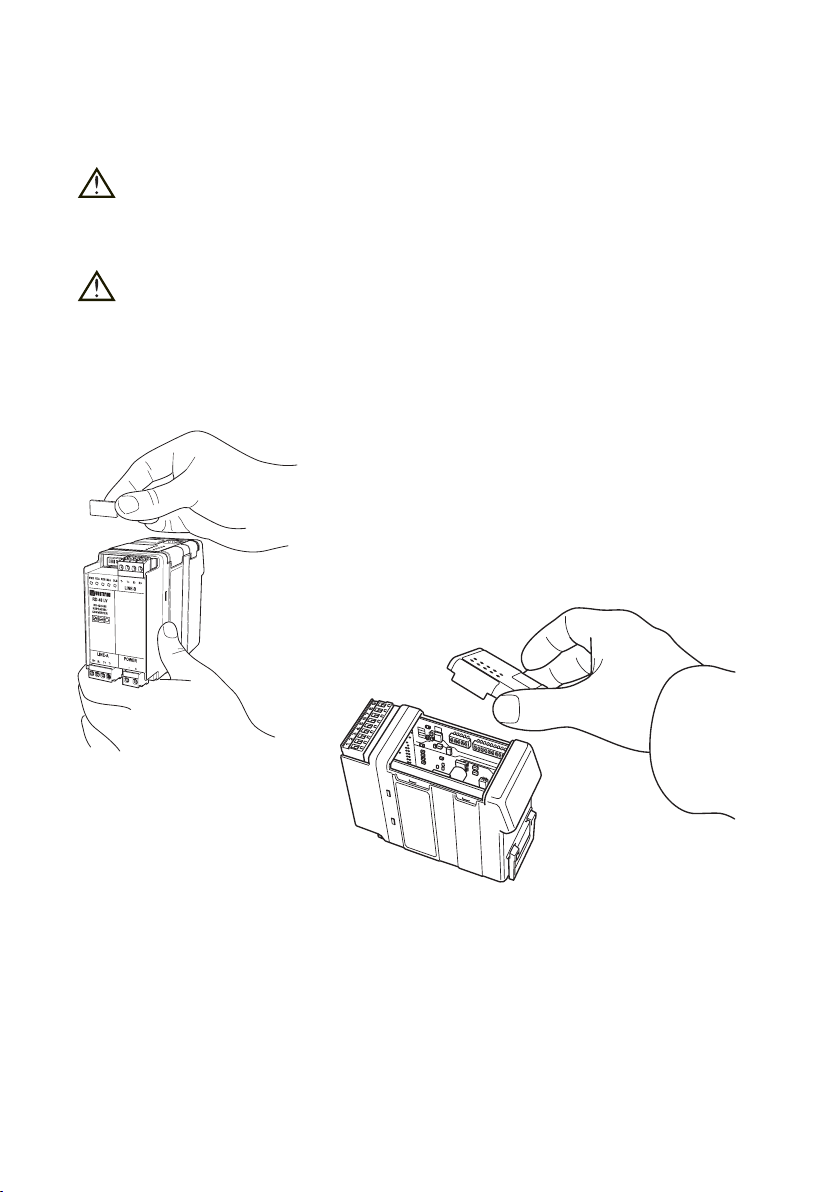
Montering
Enheten är avsedd att monteras på en 35 mm DIN skena vilken skall vara horisontellt
fastsatt, tex. på en vägg eller montageplåt i skåp.
Enheten kyls genom konvektion. För att förhindra störningar i kylande luftström kring
enheten krävs ett fritt utrymme på
25 mm ovan/nedan och 10 mm till vänster/höger om enheten.
Snäppfastsättning utan verktyg, se figur.
Min
10 mm
(0.4 inches)
25 mm
25 mm
Demontering
Pressa ner den svarta hållaren på enhetens nedre del
med hjälp av en skruvmejsel, se figur.
6153-2004
5
Page 6

6.2 Anslutningar
Line B gränssnitt
6
Line A gränssnitt
Matningsgränssnitt
6153-2004
Page 7

6.2.1 Matning (RD-48 HV)
N
L
1
2
5678943
2
1
5678943
2
1
3-polig skruvplint Beskrivning
L Spänning AC fas / Spänning DC
N Spänning AC nolla / Spänning DC
Spänning AC skyddsjord
6.2.2 Matning (RD-48 LV / RD-48 LV TEMP)
2-polig skruvplint Beskrivning
Nr. 1 Spänning DC –
Nr. 2 Spänning DC +
6.2.3 Linje A RS-422/485
4-polig skruvplint Beskrivning Beskrivning
Nr. 1 In R+ RS-422 mottagare
Nr. 2 In R– RS-422 mottagare
Nr. 3 In/Ut T+ RS-422/485 sändare/mottagare
Nr. 4 In/Ut T– RS-422/485 sändare/mottagare
6.2.4 Linje B RS-422/485
4-polig skruvplint Beskrivning Beskrivning
Nr. 1 In R+ RS-422 mottagare
Nr. 2 In R– RS-422 mottagare
Nr. 3 In/Ut T+ RS-422/485 sändare/mottagare
Nr. 4 In/Ut T– RS-422/485 sändare/mottagare
6.3 Statusindikering
6.3.1 Lysdioder
PWR LED till Matningsspänning korrekt
LED från Ingen matningsspänning
RDA LED till Mottagen data linje A
LED från Ingen data linje A
RDB LED till Mottagen data linje B
LED från Ingen data linje B
BLA LED till Blockering linje A
LED från Ingen blockering linje A
BLB LED till Blockering linje B
LED från Ingen blockering linje B
6153-2004
7
Page 8
6.4 Switchinställningar
DIP-switchar är tillgängliga under locket på toppen/fronten av modemet. DIP-switcharna
används för att konfigurera enheten.
Varning!
Potentialutjämna dig till en jordningspunkt (t ex genom att använda handledsband),
så att skada av intern elektronik på grund av elektrostatiska urladdningar (ESD)
förhindras, innan locket på modemets topp tas av.
Varning! Öppna ej ansluten enhet.
Koppla ifrån enheten från AC/DC matningsnät samt alla andra elektriska anslutningar, så att åtkomst till farliga spänningar förhindras.
8
6153-2004
Page 9

1234
S4:1-6
1
2
3
4
S1:1-6
S2:1-4
S3:1-6
Switchblock 1 – S1
Hastighet
ON
1 2 3 4 5 6
ON
1 2 3 4 5 6
ON
1 2 3 4 5 6
ON
1 2 3 4 5 6
ON
1 2 3 4 5 6
ON
1 2 3 4 5 6
ON
1 2 3 4 5 6
300 bit/s
1 200 bit/s
2 400 bit/s
4 800 bit/s
9 600 bit/s
19 200 bit/s
38 400 bit/s
Switchblock 2 – S2
Funktionsläge
ON
Retiming inaktiv
1 2 3 4
ON
Retiming aktiv
1 2 3 4
ON
Anti-blocking inaktiv
1 2 3 4
ON
Anti-blocking aktiv
1 2 3 4
ON
1 2 3 4 5 6
ON
1 2 3 4 5 6
ON
1 2 3 4 5 6
ON
1 2 3 4 5 6
ON
1 2 3 4 5 6
ON
1 2 3 4 5 6
ON
1 2 3 4 5 6
57 600 bit/s
93 750 bit/s
115,2 kbit/s
187,5 kbit/s
375 kbit/s
500 kbit/s
1 500 kbit/s
Linje A Linje B
ON
4-tråd
1 2 3 4
ON
1 2 3 4
2-tråd
Formatinställningar
ON
1 2 3 4 5 6
ON
1 2 3 4 5 6
ON
1 2 3 4 5 6
ON
1 2 3 4 5 6
Vändtid 1–2 bitar vid samtliga
hastigheter och format.
ON
1 2 3 4
ON
1 2 3 4
9 bitar
format
10 bitar
format
11 bitar
format
Synkront
format
4-tråd
2-tråd
6153-2004
9
Page 10

Switchblock 3 – S3
RS-422/485 inställning Linje-A
ON
1 2 3 4 5 6
ON
1 2 3 4 5 6
Inaktiv
fail-safe 4-tråd
Aktiv
fail-safe 4-tråd
ON
1 2 3 4 5 6
ON
1 2 3 4 5 6
Inaktiv
fail-safe 2-tråd
Aktiv
fail-safe 2-tråd
ON
1 2 3 4 5 6
ON
1 2 3 4 5 6
Ingen terminering
4-tråd
Terminering
4-tråd
ON
1 2 3 4 5 6
ON
1 2 3 4 5 6
Switchblock 4 –S4
RS-422/485 inställning Linje-B
ON
1 2 3 4 5 6
ON
1 2 3 4 5 6
ON
1 2 3 4 5 6
ON
1 2 3 4 5 6
Inaktiv
fail-safe 4-tråd
Aktiv
fail-safe 4-tråd
Ingen terminering
4-tråd
Terminering
4-tråd
ON
1 2 3 4 5 6
ON
1 2 3 4 5 6
ON
1 2 3 4 5 6
ON
1 2 3 4 5 6
Fabriksinställning
S1
S2
ON
1 2 3 4 5 6
ON
1 2 3 4
9 600 bit/s,
10 bitar format
Anti blocking aktiv,
Retiming inaktiv
Ingen terminering
2-tråd
Terminering
2-tråd
Inaktiv
fail-safe 2-tråd
Aktiv
fail-safe 2-tråd
Ingen terminering
2-tråd
Terminering
2-tråd
ON
S3
1 2 3 4 5 6
ON
S4
1 2 3 4 5 6
Ingen terminering,
inaktiv fail-safe
Ingen terminering,
inaktiv fail-safe
10
6153-2004
Page 11

7. Funktionsbeskrivning
1
2
3
4
LINE-A LINE-B
T+
T–
T+
T–
1
2
3
4
LINE-A LINE-B
T+
T–
T+
T–
R+ R+
R– R–
1
2
3
4
LINE-A LINE-B
T+
T–
T+
T–
R+
R–
7.1 Driftsätt
RS-485 repeater
Detta driftsätt används för att utöka
antalet laster eller längden på en 2-tråds
(RS-485) bus.
RS-422 repeater
Detta driftsätt används för att utöka antalet
laster eller längden på en 4-tråds (RS-422)
bus.
RS-422/485 converter
Detta driftsätt används för att omvandla
2-tråds (RS-485) till/från 4-tråds (RS-422)
kommunikation.
OBS! R+/R–, T+/T– definitionerna är ej standardiserade.
Det kan hjälpa att skifta polaritet om enheten inte fungerar.
6153-2004
11
Page 12

7.2 Val av datahastighet och format
Datahastighet och format används för att bestämma vändtiden på RS-422/485 bussen.
För att optimera funktionen måste datahastighet och format ställas in enligt det använda
protokollet.
Switcharna för datahastighet ställer in hastighet på både linje A och linje B.
Observera att RD-48 är en transparant enhet och att datahastigheten måste vara den
samma på båda sidor av enheten.
Med formatswitcharna väljer man format på både linje A och linje B. 9-, 10- eller 11-bitars
format används för asynkrona protokoll. Synkront format innebär att sändaren aktiveras i
11 bitar efter en detekterad data bit.
7.3 Inställning av retiming
Retiming är möjlig på de högre datahastigheterna (187,5 kbit/s och högre).
Retiming åter skapar databitarna till rätt bitlängd beroende på inställd hastighet.
Användandet av retiming gör det möjligt att koppla in ett större antal RD-48 i serie.
7.4 Inställning av anti-blocking
Anti- blocking funktionen säkrar kommunikationen på båda sidor om RD-48 repeatern.
Om linjen är konstant aktiv (blockerad) i mer än 50 ms kommer anti-blocking funktionen
att bryta förbindelsen på den sidan av repeatern. Detta gör det möjligt att kommunicera
mellan enheter på andra sidan av repeatern. När linjen blir återställd kommer repeatern
automatiskt att återuppta förbindelsen.
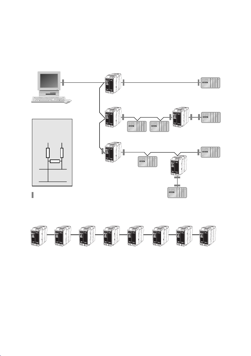
7.5 Val av RS-422/485 struktur
Ett standard RS-422/485 system skall alltid vara i form av en busstruktur. Om man
använder RD-48 är det möjligt att konstruera stjärnnät. Det är viktigt att terminera
RS-422/485 nät för att förhindra reflektioner och störningar i systemet, RD-48 är
beroende av detta för en korrekt funktion.
I ett standardnätverk skall fail-safe funktionen också vara inkopplad. Fail-safe tvingar mottagaren till en definierad nivå då inkopplad sändare är inaktiv. Detta gör systemet mindre
stör känsligt.
Vi rekommenderar inställning av terminering och fail-safe enligt applikationsexemplet.
12
6153-2004
Page 13

8. Blockdiagram
1
2
3
S4
4
5
6
S3
1
2
3
S3
Insulated
power
supply
6153-2004
13
Page 14

9. Applikationsexempel
RD-48
RD-48
RD-48
RD-48RD-48 RD-48 RD-48 RD-48 RD-48 RD-48 RD-48
RD-48
RD-48
+5V 0V
Linje
Terminering
och fail-safe
R–
R+
= Terminering och fail-safe
OBS! Maximalt 8 repeaters är möjligt att koppla i serie
1
2
3
4
1
2
3
4
1
2
3
4
1
2
3
4
1
2
3
4
1
2
3
4
1
2
3
4
1
2
3
4
1
2
3
4
1
2
3
4
1
2
3
4
1
2
3
4
1
2
3
4
En typisk applikation är om man behöver koppla nätet som ett stjärnnät.
Detta tillåter normalt inte RS-422/485. Ansluter man en RD-48 repeater
i varje grenkoppling (max 30 cm från bussen) kan förgreningarna förlängas
ända upp till 1200 m.
Observera terminering och fail-safe-inställningarna i nätet.
14
6153-2004
Page 15

Contents
1. Introduction ............................................................................................................................................................ 16
2. Safety ................................................................................................................................................................................ 16
3. Approvals ..................................................................................................................................................................... 16
3.1 Declaration of Conformity ....................................................................................................... 56 – 57
4. Specifications ......................................................................................................................................................... 17
4.1 Connections ...................................................................................................................................................... 17
4.2 Insulation between interfaces ............................................................................................................. 17
4.3 Climatic environment ............................................................................................................................... 17
4.4 Mechanics ............................................................................................................................................................ 18
5. Maintenance ............................................................................................................................................................ 18
6. Installation .................................................................................................................................................... 18 – 23
6.1 Mounting/Removal ....................................................................................................................................... 18
6.2 Connections ...................................................................................................................................................... 19
6.2.1 Power (RD-48 HV) ............................................................................................................................. 20
6.2.2 Power (RD-48 LV/RD-48 LV TEMP) ...................................................................................... 20
6.2.3 Line A RS-422/485 .............................................................................................................................. 20
6.2.4 Line B RS-422/485 .............................................................................................................................. 20
6.3 Indicators ............................................................................................................................................................. 20
6.3.1 LED indicators ...................................................................................................................................... 20
6.4 DIP switch settings ......................................................................................................................... 21 – 23
7. Functional description ................................................................................................................. 24 – 25
7.1 Operating modes .......................................................................................................................................... 24
7.2 Selection of data rate/format .............................................................................................................. 25
7.3 Setting and retiming .................................................................................................................................. 25
7.4 Setting and anti-blocking ........................................................................................................................ 25
7.5 Selection of RS-422/485 setting ......................................................................................................... 25
8. Block diagram ...................................................................................................................................................... 26
9. Application example .................................................................................................................................... 27
6153-2004
15
Page 16

1. Introduction
The RD-48, is an industrial repeater for RS-422/485 buses. It can also be used as
an converter between 2- and 4-wire systems or as an isolator to protect for example
a PLC from transients or overvoltage.
The standard RS-422/485 bus supports 32 nodes at a distance of 1200 meters.
The RD-48 gives you another 31 nodes and further max.1200 meters. The RD-48
is designed to be mounted on a standard 35 mm DIN-rail.
2. Safety
General:
Before using this unit, read this manual completely and gather all information on
the unit. Make sure that you understand it fully. Check that your application does
not exceed the safe operating specifications for this unit.
Before installation, maintenance or modification work:
Prevent damage to internal electronics from electrostatic discharges (ESD)
by discharging your body to a grounding point (e.g. use of wrist strap).
Prevent access to hazardous voltages by disconnecting the unit from AC/DC
mains supply and all other electrical connections.
Installation:
This unit should only be installed by qualified personnel.
This unit should only be installed in a “restricted access area”, for example
a lockable cabinet where access is restricted to service personnel only.
This unit is intended for permanent connection to the AC/DC mains supply.
The power supply wiring must be sufficiently fused, and if necessary it must be
possible to disconnect manually from the AC/DC mains supply. Ensure compliance
to national installation regulations.
Unit with the rated voltage exceeding 42.4 V peak or 60 VDC, is defined as class I
equipment with a protective earthing conductor terminal.
Unit with the rated voltage up to 42.4 V peak or 60 VDC, is defined as class III
equipment and shall be separated from hazardous voltage by double or reinforced
insulation.
This unit uses convection cooling. To avoid obstructing the air flow around the
unit, follow the spacing recommendations (see under chapter Installation).
3. Approvals
Conformity with the Directive 2006/95/EC (Low Voltage Directive) has been assessed by
application of the standard EN 60950-1.
Conformity with the Directive 2004/108/EC (Electromagnetic compatibility)
has been assessed by application of standards EN 61000-6-2 (industrial immunity)
and EN 61000-6-3 (residential emission).
16
6153-2004
Page 17

4. Specifications
4.1 Connections
Power interface
Model description RD-48 LV RD-48 LV TEMP RD-48 HV
Rated voltage 12–48 VDC 95–240 VAC
110–250 VDC
Operating voltage 9.6–57.6 VDC 85.5–264 VAC
88–300 VDC
Rated current 300 mA 50 mA
Rated frequency – 48–62 Hz
Polarity Reverse polarity protected Polarity independent
Connection 2-position screw terminal 3-position screw terminal
Connector size 0.2 – 2.5 mm² (AWG 24-12)
Fuse To be externally fused.
RS-422/485 interface – Line A
Electrical specification RS-422/485
Data rate 300 bit/s – 1.5 Mbit/s
Connection 4-position screw terminal
Connector size 0.2 – 2.5 mm² (AWG 24-12)
Circuit type TNV-1
RS-422/485 interface – Line B
Electrical specification RS-422/485
Data rate 300 bit/s – 1.5 Mbit/s
Connection 4-position screw terminal
Connector size 0.2 – 2.5mm² (AWG 24-12)
Circuit type TNV-1
4.2 Insulation between interfaces
Power (RD-48 HV) to all other 3.0 kV RMS @ 50Hz and 60 s duration
Power (RD-48 LV) to all other 1.0 kV RMS @ 50Hz and 60 s duration
Line-A to Line-B 1.5 kV RMS @ 50Hz and 60 s duration
4.3 Climatic environment
Temperature, operating 5 to 55°C
–40 to 70°C (TEMP version)
Temperature, storage and transportation –40 to 70°C
Relative humidity, operating 5 to 95% (non-condensing)
Relative humidity, storage and transportation 5 to 95% (condensation allowed
outside packaging)
6153-2004
17
Page 18

4.4 Mechanics
CLICK!
Dimension (W x H x D) 55 x 128 x 100 mm
Weight 0.3 kg
Mounting Snap on mounting to 35 mm DIN-rail
Degree of protection IP 20 (IEC 529)
5. Maintenance
No maintenance is required, as long as the unit is used as
intended within the specified conditions.
6. Installation
6.1 Mounting / Removal
Before mounting or removing the unit:
Prevent damage to internal electronics from electrostatic
discharges (ESD) by discharging your body to a grounding
point (e.g. use of wrist strap).
Prevent access to hazardous voltages by disconnecting
the unit from AC/DC mains supply and all other electrical
connections.
Mounting
This unit should be mounted on 35 mm DIN-rail which is horizontally mounted on a wall
or cabinet backplate.
This unit use convention cooling. To avoid obstructions to the airflow around the unit,
use the following spacing rules. Recommended spacing 25 mm (1.0 inch) above/below and
10 mm (0.4 inches) left/right the unit.
Snap on mounting, see figure
Min
10 mm
(0.4 inches)
25 mm
25 mm
Removal
Press down the black support at the back of the unit
using a screwdriver, see figure.
18
6153-2004
Page 19

6.2 Connections
Line B interface
6153-2004
Line A interface
Power interface
19
Page 20

6.2.1 Power (RD-48 HV)
N
L
1
2
5678943
2
1
5678943
2
1
3-pos screw terminal Description
L Power AC line / Power DC
N Power AC neutral / Power DC
Power AC protective earth
6.2.2 Power (RD-48 LV / RD-48 LV TEMP)
2-pos screw terminal Description
No. 1 Power DC –
No. 2 Power DC +
6.2.3 Line A RS-422/485
4-pos screw terminal Direction Description
No. 1 In R+ RS-422 receiver
No. 2 In R– RS-422 receiver
No. 3 In/Out T+ RS-422/485 transmitter/receiver
No. 4 In/Out T– RS-422/485 transmitter/receiver
6.2.4 Line B RS-422/485
4-pos screw terminal Direction Description
No. 1 In R+ RS-422 receiver
No. 2 In R– RS-422 receiver
No. 3 In/Out T+ RS-422/485 transmitter/receiver
No. 4 In/Out T– RS-422/485 transmitter/receiver
6.3 Indicators
6.3.1 LED indicators
PWR LED on Internal power correct
LED off No internal power
RDA LED on Received data line A
LED off No data line A
RDB LED on Received data line B
LED off No data line B
BLA LED on Blocking line A
LED off No blocking line A
BLB LED on Blocking line B
LED off No blocking line B
20
6153-2004
Page 21

6.4 DIP switch settings
DIP-switches is assessable under the lid on top/front of the unit. DIP-switches is used
to configure the modem.
Warning!
Prevent damage to internal electronics from electrostatic discharges (ESD) by
discharging your body to a grounding point (e.g. use of wrist strap), before the
lid on top of the modem is removed.
Warning! Do not open connected equipment.
Prevent access to hazardous voltages by disconnecting the unit from AC/DC mains
supply and all other electrical connections.
6153-2004
21
Page 22

Switch block 1 – S1
1234
S4:1-6
1
2
3
4
S1:1-6
S2:1-4
S3:1-6
Data rate
ON
1 2 3 4 5 6
ON
1 2 3 4 5 6
ON
1 2 3 4 5 6
ON
1 2 3 4 5 6
ON
1 2 3 4 5 6
ON
1 2 3 4 5 6
ON
1 2 3 4 5 6
Switch block 2 – S2
Operating mode
ON
1 2 3 4
ON
1 2 3 4
ON
1 2 3 4
ON
1 2 3 4
300 bit/s
1 200 bit/s
2 400 bit/s
4 800 bit/s
9 600 bit/s
19 200 bit/s
38 400 bit/s
Retiming inactive
Retiming active
Anti-blocking inactive
Anti-blocking active
ON
1 2 3 4 5 6
ON
1 2 3 4 5 6
ON
1 2 3 4 5 6
ON
1 2 3 4 5 6
ON
1 2 3 4 5 6
ON
1 2 3 4 5 6
ON
1 2 3 4 5 6
57 600 bit/s
93 750 bit/s
115,2 kbit/s
187,5 kbit/s
375 kbit/s
500 kbit/s
1 500 kbit/s
Line A Line B
ON
4-wire
1 2 3 4
ON
1 2 3 4
2-wire
Format settings
ON
1 2 3 4 5 6
ON
1 2 3 4 5 6
ON
1 2 3 4 5 6
ON
1 2 3 4 5 6
1–2 bits turning time at all
speed and format settings
9 bits
format
10 bits
format
11 bits
format
Synchronous
format
ON
1 2 3 4
ON
1 2 3 4
4-wire
2-wire
22
6153-2004
Page 23

Switch block 3 – S3
RS-422/485 setting Line-A
ON
1 2 3 4 5 6
ON
1 2 3 4 5 6
Inactive
fail-safe 4-wire
Active
fail-safe 4-wire
ON
1 2 3 4 5 6
ON
1 2 3 4 5 6
Inactive
fail-safe 2-wire
Active
fail-safe 2-wire
ON
1 2 3 4 5 6
ON
1 2 3 4 5 6
No termination
4-wire
Termination
4-wire
Switch block 4 – S4
RS-422/485 setting Line-B
ON
1 2 3 4 5 6
ON
1 2 3 4 5 6
ON
1 2 3 4 5 6
ON
1 2 3 4 5 6
Inactive
fail-safe 4-wire
Active
fail-safe 4-wire
No termination
4-wire
Termination
4-wire
Factory settings
S1
S2
ON
1 2 3 4 5 6
ON
1 2 3 4
9 600 bit/s,
10 bit format
Anti blocking active,
Retiming inactive
ON
1 2 3 4 5 6
ON
1 2 3 4 5 6
ON
1 2 3 4 5 6
ON
1 2 3 4 5 6
ON
1 2 3 4 5 6
ON
1 2 3 4 5 6
S3
S4
No termination
2-wire
Termination
2-wire
Inactive
fail-safe 2-wire
Active
fail-safe 2-wire
No termination
2-wire
Termination
2-wire
ON
1 2 3 4 5 6
ON
1 2 3 4 5 6
No terminataion,
inactive fail-safe
No terminataion,
inactive fail-safe
6153-2004
23
Page 24

7. Functional description
1
2
3
4
LINE-A LINE-B
T+
T–
T+
T–
1
2
3
4
LINE-A LINE-B
T+
T–
T+
T–
R+ R+
R– R–
1
2
3
4
LINE-A LINE-B
T+
T–
T+
T–
R+
R–
7.1 Operating modes
RS-485 repeater
This operating mode is used to extend /
increase number of loads on a 2-wire
(RS-485) bus.
RS-422 repeater
This operating mode is used to extend /
increase number of loads on a 4-wire
(RS-422) bus.
RS-422/485 converter
This operating mode is used to convert
between 2- (RS-485) and 4-wire (RS-422)
communication.
N.B! R+/R–, T+/T– definitions are not standard. It can help to switch polarity.
24
6153-2004
Page 25

7.2 Selection of datarate / format
The data rate and format settings is used to decide the turning time on the RS-422/485
bus. For optimum performance the data rate and format settings needs to be set up
according to the used protocol.
The data rate switches selects the operating speed on both line-A and line-B. Observe
that the RD-48 is a transparent unit and the data rate needs to be the same on both
sides of the unit.
The format switches selects the data format on both line-A and line-B. 9,10 or 11-bit
format is used for asynchronous protocols. Synchronous mode activates the transmitter
for 11 bits after a detected edge in data. This mode is used for synchronous protocols.
7.3 Setting of retiming
Retiming is possible on higher data rates (187.5 kbit/s and higher) and recreates the
data bits to exact bit length set up by the speed selection. The use of retiming makes
it possible to connect an increased number of RD-48 units on a line.
7.4 Setting of anti-blocking
The anti blocking function secures transmission on each side of the RD-48 repeater.
If the line is constant active (blocked) for more than 50 ms the anti blocking function
will disconnect this side of the repeater. This makes it possible to communicate between
units on the other side of the repeater. When the line is cleared the repeater will automatically reconnect the disconnected side.
7.5 Selection of RS-422/485 setting
When an RS-422/485 system is installed it should always form a bus structure. Using
the RD-48, it is possible to produce a star network of several busses. It is important to
terminate RS-422/485 equipment correctly. In standard networks the fail-safe function
should also be connected which is provided to push the unit to a defined state when
the RS-422/485 line becomes undefined. The RD-48 relies on this for operation.
We recommend connection of termination and fal-safe as shown in the application note.
6153-2004
25
Page 26

8. Block diagram
1
2
3
S4
4
5
6
S3
1
2
3
S3
Insulated
power
supply
26
6153-2004
Page 27
9. Application example
RD-48
RD-48
RD-48
RD-48RD-48 RD-48 RD-48 RD-48 RD-48 RD-48 RD-48
RD-48
RD-48
+5V 0V
Line
Termination
and fail-safe
R–
R+
= Termination and fail-safe
Note ! It is not possible to have more than 8 repeaters in serial connection
1
2
3
4
1
2
3
4
1
2
3
4
1
2
3
4
1
2
3
4
1
2
3
4
1
2
3
4
1
2
3
4
1
2
3
4
1
2
3
4
1
2
3
4
1
2
3
4
1
2
3
4
Normally star networks is not allowed in RS-422/485 applications. Using the RD-48
makes it possible to create branches up to 1200 m. Observe that the RD-48 should be
connected a maximum of 30 cm from the bus.
Observe setting of termination and fail-safe.
6153-2004
27
Page 28

Inhalt
1. Einleitung .................................................................................................................................................................... 31
2. Sicherheitshinweise ....................................................................................................................................... 31
3. Zulassungen ............................................................................................................................................................. 31
3.1 Konformitätserklärung (Declaration of Conformity) .......................................... 56 – 57
4. Technische Daten .............................................................................................................................................. 32
4.1 Anschlüsse ........................................................................................................................................................... 32
4.2 Isolation zwischen Schnittstellen ..................................................................................................... 32
4.3 Umgebungsbedingungen ......................................................................................................................... 32
4.4 Mechanische Daten ..................................................................................................................................... 33
5. Wartung ........................................................................................................................................................................ 33
6. Installation .................................................................................................................................................... 33 – 38
6.1 Installation/Deinstallation ...................................................................................................................... 33
6.2 Anschlüsse ........................................................................................................................................................... 34
6.2.1 Spannungsversorgung (RD-48 HV) ...................................................................................... 35
6.2.2 Spannungsversorgung (RD-48 LV/RD-48 LV TEMP) ................................................ 35
6.2.3 Leitungsanschluss A RS-422/485 ............................................................................................. 35
6.2.4 Leitungsanschluss B RS-422/485 ............................................................................................. 35
6.3 Anzeigen ............................................................................................................................................................... 35
6.3.1 LED Anzeigen ........................................................................................................................................ 35
6.4 DIP-Schalter Einstellung ............................................................................................................ 36 – 38
7. Funktionsbeschreibung ............................................................................................................... 39 – 40
7.1 Betriebsarten ................................................................................................................................................... 39
7.2 Einstellung Datenrate/Format ............................................................................................................ 40
7.3 Einstellung und Retiming ........................................................................................................................ 40
7.4 Einstellung und Antiblocking ................................................................................................................ 40
7.5 Einstellung RS-422/485 ............................................................................................................................. 40
8. Blockschaltbild ..................................................................................................................................................... 41
9. Applikationsbeispiele ................................................................................................................................... 43
30
6153-2004
Page 29

1. Einleitung
Der RD-48 ist ein industrieller Repeater für RS-422/485 Busnetze. Desweiteren kann er
als Konverter zwischen 2- und 4-Draht Systemen eingesetzt werden, und als Isolator zum
Schutz vor Transienten oder Überspannungen.
Der Standard RS-422/485 Bus unterstützt 32 Slaves bei einer Distanz von 1200 m.
Der RD-48 ermöglicht weitere 31 Slaves und max. 1200 m. Der RD-48 ist für die
Montage auf einer Standard 35 mm Hutschiene entwickelt.
2. Sicherheitshinweise
Allgemeines:
Vor dem Einsatz des Gerätes ist die Bedienungsanleitung vollständig zu lesen.
Überprüfen Sie, dass der Einsatz dieser Geräte keine Vorschriften verletzt, und den
Spezifikationen des Geräts entspricht.
Vor der Installation, Wartung oder Modifikation:
Vermeiden Sie Schaden an der Elektronik durch elektrostatische Aufladung (ESD)
indem Sie sich vorher an einem Erdpunkt entladen (z.B. Einsatz eines
Erdarmbandes).
Vermeiden Sie durch Abziehen der Spannungsversorgung, dass stromführende Teile
berührt werden können.
Installation:
Es sollte nur in einem gesicherten Umfeld betrieben werden, zu dem nur
Servicepersonal Zutritt hat.
Die Einheit ist zum permanenten Anschluss an AC/DC Spannungsversorgungen
gedacht und darf nur von geeignetem Personal installiert werden.
Die AC/DC Versorgungsleitungen sind ausreichend abzusichern, und eine manuelle
Unterbrechungsmöglichkeit ist bei Bedarf vorzusehen. Beachten Sie auch die
nationalen Vorschriften zu diesem Thema.
Ein Gerät welches mit mehr als 42.4V Spitze oder 60V DC arbeitet, ist als
Class I Gerät mit Schutzerde Anschluss ausgewiesen.
Ein Gerät welches mit weniger als 42.4V Spitze oder 60V DC arbeitet, ist als
Class III Gerät ausgewiesen, und sollte gegenüber Hochspannungen, durch
verdoppelte oder externe Isolationen, separiert werden.
Zur Kühlung des Gerätes wird die Außenluft benutzt, daher sollte die
Luftströmung um das Gerät nicht gestört sein. Siehe Installationshinweise.
3. Zulassungen
Die Konformität zur Direktive 2006/95/EC (Niederspannungs Richtlinien) wurde durch
das Einbinden des Standards EN 60950-1 erzielt.
Die Konformität mit der Richtlinie 2004/108/EC (Elektromagnetische Kompatibilität)
wurde durch Einbinden des Applikationsstandards EN 61000-6-2 (industrielle
Beeinflussung) und EN 61000-6-3 (industrielle Austrahlung) erzielt.
6153-2004
31
Page 30

4. Technische Daten
4.1 Anschlüsse
Spannungsversorgung
Modelbeschreibung RD-48 LV RD-48 LV TEMP RD-48 HV
Eingangsspannung 12–48 VDC 95–240 VAC
110–250 VDC
Betriebsspannung 9.6–57.6 VDC 85.5–264 VAC
88–300 VDC
Stromaufnahme 300 mA 50 mA
Frequenz – 48–62 Hz
Polarität Verpolungsschutz Polungsunabhängig
Anschluss 2-pol. Schraubklemme 3-pol. Schraubklemme
Anschlussgröße 0.2 – 2.5 mm² (AWG 24-12)
Sicherung Muss extern abgesichert werden
RS-422/485 Schnittstelle – Leitung A
Elektrische Daten RS-422/485
Übertragungsrate 300 – 1,5 Mbit/s
Anschluss 4 pol. Schraubklemme
Anschlusgrösse 0,2 – 2,5 mm² (AWG 24-12)
Anschlusstyp TNV-1
RS-422/485 Schnittstelle – Leitung B
Elektrische Daten RS-422/485
Übertragungsrate 300 – 1,5 Mbit/s
Anschluss 4 pol. Schraubklemme
Anschlusgrösse 0.2 – 2.5 mm² (AWG 24-12)
Anschlusstyp TNV-1
4.2 Isolation zwischen Schnittstellen
Spannung (RD-48 HV) zu allen 3,0 kV RMS @ 50 Hz und 60 s Dauer
Spannung (RD-48 LV) zu allen 1,0 kV RMS @ 50 Hz und 60 s Dauer
Leitung A zu Leitung B 1,5 kV RMS @ 50 Hz und 60 s Dauer
4.3 Klimatische Bedingungen
Betriebstemperatur 5 bis 55°C
–40 bis 70°C (TEMP version)
Lager- und Transporttemperatur –40 bis 70°C
Relative Luftfeuchtigkeit, Betrieb 5 bis 95% nicht kondensierend
Relative Luftfeuchtigkeit, Lager- und Transport 5 bis 95% kondensierend außerhalb
Verpackung
32
6153-2004
Page 31

4.4 Mechanisch
CLICK!
Abmessungen (BxHxT) 55 x 128 x 100 mm
Gewicht 0,3 kg
Montage Schnappbar auf 35 mm DIN-Hutschiene
Schutzklasse IP 20 (IEC 529)
5. Wartung
Es sind keine Wartungsarbeiten notwendig, solange das Gerät
innerhalb seiner Spezifikation eingesetzt wird.
6. Installation
6.1 Montage/Demontage
Vor der Montage oder Demontage des Geräts:
Vermeiden Sie Schaden an der Elektronik durch elektrostatische Aufladung (ESD) indem Sie sich vorher an
einem Erdpunkt entladen (z.B. Einsatz eines
Erdarmbandes).
Um ein Berühren spannungsführender Teile zu vermeiden,
ist das Gerät vor der Montage/Demontage von allen
Spannungsführenden Teilen abzuklemmen.
Montage
Das Gerät ist für die Montage auf einer horizontalen 35mm Hutschiene vorgesehen.
Zur Kühlung des Gerätes müssen bestimmte Mindestabstände eingehalten werden. Über
und unter dem Gerät min. 25mm (1.0 Inch) und links und rechts min. 10mm (0.4 Inches).
Aufschnapp Montage (Skizze)
Min
10 mm
(0.4 inches)
25 mm
25 mm
Demontage
Die schwarze Halterung auf der Unterseite mit einem
Schraubendreher nach unten ziehen und das Gerät nach
oben von der Hutschiene nehmen (Skizze).
6153-2004
33
Page 32

6.2 Anschlüsse
Leitungsschnittstelle B
Leitungsschnittstelle A
34
Spannungsanschluss
6153-2004
Page 33

6.2.1 Spannungsversorgung (RD-48 HV)
N
L
1
2
5678943
2
1
5678943
2
1
3-pol. Schraubklemme Beschreibung
L Phase
N Neutralleiter
Schutzerde
6.2.2 Spannungsversorgung (RD-48 LV / RD-48 LV TEMP)
2-pol. Schraubklemme Beschreibung
Nr. 1 – Spannung
Nr. 2 + Spannung
6.2.3 Leitungsschnittstelle A RS-422/485
4-pol. Schraubklemme Richtung Beschreibung
Nr. 1 In R+ RS-422 Empfänger
Nr. 2 In R– RS-422 Empfänger
Nr. 3 In/Out T+ RS-422/485 Sender/Empfänger
Nr. 4 In/Out T– RS-422/485 Sender/Empfänger
6.2.4 Leitungsschnittstelle B RS-422/485
4-pol. Schraubklemme Richtung Beschreibung
Nr. 1 In R+ RS-422 Empfänge
Nr. 2 In R– RS-422 Empfänge
Nr. 3 In/Out T+ RS-422/485 Sender/Empfänger
Nr. 4 In/Out T– RS-422/485 Sender/Empfänger
6.3 Anzeigen
6.3.1 LED Anzeigen
PWR LED An Spannungsversorgung OK
LED Aus Keine interne Spannung
RDA LED An Empfangene Daten an Leitung A
LED Aus Keine Daten an Leitung A
RDB LED An Empfangene Daten an Leitung B
LED Aus Keine Daten an Leitung B
BLA LED An Blocking auf Leitung A
LED Aus Kein Blocking auf Leitung A
BLB LED An Blocking auf Leitung B
LED Aus Kein Blocking auf Leitung B
6153-2004
35
Page 34

6.4 DIP-Schalter Einstellung
Die DIP-Schalter sind über die obere Abdeckung zugänglich. Über die DIP-Schalter kann
das Gerät konfiguriert werden.
WARNUNG!
Vermeiden Sie Schaden an der Elektronik durch elektrostatische Aufladung
(ESD) indem Sie sich vorher an einem Erdpunkt entladen
(z.B. Einsatz eines Erdarmbandes), bevor sie den Deckel abnehemen.
WARNUNG! Keine angeschlossenen Geräte öffnen.
Um ein Berühren spannungsführender Teile zu vermeiden, ist das Gerät vor der
Montage/Demontage von allen Spannungsführenden Teilen abzuklemmen.
36
6153-2004
Page 35

1234
S4:1-6
1
2
3
4
S1:1-6
S2:1-4
S3:1-6
DIP-Schalterblock 1 – S1
Übertragungsrate
ON
1 2 3 4 5 6
ON
1 2 3 4 5 6
ON
1 2 3 4 5 6
ON
1 2 3 4 5 6
ON
1 2 3 4 5 6
ON
1 2 3 4 5 6
ON
1 2 3 4 5 6
300 Bit/s
1 200 Bit/s
2 400 Bit/s
4 800 Bit/s
9 600 Bit/s
19 200 Bit/s
38 400 Bit/s
ON
1 2 3 4 5 6
ON
1 2 3 4 5 6
ON
1 2 3 4 5 6
ON
1 2 3 4 5 6
ON
1 2 3 4 5 6
ON
1 2 3 4 5 6
ON
1 2 3 4 5 6
DIP-Schalterblock 2 – S2
Betriebsart
ON
Retiming inaktiv
1 2 3 4
ON
Retiming aktiv
1 2 3 4
ON
Anti Blocking inaktiv
1 2 3 4
ON
Anti Blocking aktiv
1 2 3 4
Formateinstellung
57 600 Bit/s
93 750 Bit/s
115,2 Kbit/s
187,5 Kbit/s
375 Kbit/s
500 Kbit/s
1 500 Kbit/s
ON
1 2 3 4 5 6
ON
1 2 3 4 5 6
ON
1 2 3 4 5 6
ON
1 2 3 4 5 6
1-2 Bits Umschaltzeit bei allen
Geschwindigkeiten und
Formateinstellungen
9 Bits
Format
10 Bits
Format
11 Bits
Format
Synchronformat
Leitung A Leitung B
ON
1 2 3 4
ON
1 2 3 4
4-Draht
2-Draht
ON
1 2 3 4
ON
1 2 3 4
4-Draht
2-Draht
6153-2004
37
Page 36

DIP-Schalterblock 3 – S3
RS-422/485 Einstellungen Leitung A
ON
1 2 3 4 5 6
ON
1 2 3 4 5 6
4-Draht
Failsafe Deaktiviert
4-Draht
Failsafe Aktiviert
ON
1 2 3 4 5 6
ON
1 2 3 4 5 6
2-Draht
Failsafe Deaktiviert
2-Draht
Failsafe Aktiviert
ON
1 2 3 4 5 6
ON
1 2 3 4 5 6
Keine Termination
4-Draht
Termination
4-Draht
ON
1 2 3 4 5 6
ON
1 2 3 4 5 6
DIP-Schalterblock 4 – S4
RS-422/485 Einstellungen Leitung B
ON
1 2 3 4 5 6
ON
1 2 3 4 5 6
ON
1 2 3 4 5 6
ON
1 2 3 4 5 6
4-Draht
Failsafe Deaktiviert
4-Draht
Failsafe Aktiviert
Keine Termination
4-Draht
Termination
4-Draht
ON
1 2 3 4 5 6
ON
1 2 3 4 5 6
ON
1 2 3 4 5 6
ON
1 2 3 4 5 6
Werkseinstellung
S1
S2
ON
1 2 3 4 5 6
ON
1 2 3 4
9600Bit/s
10 Bit Format
Anti Blocking aktiv,
Retiming inaktiv
S3
S4
Keine Termination
2-Draht
Termination
2-Draht
2-Draht
Failsafe Deaktiviert
2-Draht
Failsafe Aktiviert
Keine Termination
2-Draht
Termination
2-Draht
ON
1 2 3 4 5 6
ON
1 2 3 4 5 6
Keine Termination,
Fail Safe inaktiv
Keine Termination,
Fail Safe inaktiv
38
6153-2004
Page 37

7. Funktionsbeschreibung
1
2
3
4
LINE-A LINE-B
T+
T–
T+
T–
1
2
3
4
LINE-A LINE-B
T+
T–
T+
T–
R+ R+
R– R–
1
2
3
4
LINE-A LINE-B
T+
T–
T+
T–
R+
R–
7.1 Betriebsarten
RS-485 Repeater
Zur Erweiterung der Leitungslänge
und Anzahl der Lasten auf einem 2-Draht
RS-485 Bus.
RS-422 Repeater
Zur Erweiterung der Leitungslänge
und Anzahl der Lasten auf einem 4-Draht
RS-422 Bus.
RS-422/485 Konverter
Wird benutzt, um zwischen 2-Draht RS-485
und 4-Draht RS-422 Netzen zu wandeln.
Hinweis: R+/R-, T+/T- sind keine Standards. Bei Problemen hilft es
oftmals die Polarität zu tauschen.
6153-2004
39
Page 38

7.2 Einstellung der Datenrate / Format
Durch diese Einstellung wird die Umschaltzeit des RS-485/422 Bus beeinflusst. Für einen
optimalen Betrieb muss die Datenrate und das Datenformat auf das benutzte Protokoll
angepasst werden.
Der DIP-Schalter für die Datenrate beeinflusst beide (A & B) Schnittstellen. Beachten Sie
bitte, dass der RD-48 ein transparenter Repeater ist, und daher die Datenrate auf beiden
Schnittstellen gleich sein muss.
Der Format Schalter stellt für beide Schnittstellen 9, 10 oder 11 Bit für asynchrone
Protokolle ein. Bei synchroner Betriebsart bleibt der Sender für 11 Bits nach einer
Flanke in den daten eingeschaltet. Dies wird nur bei synchronen Protokollen benutzt.
7.3 Retiming Einstellung
Retiming ist bei höheren (187.5Kbit/s oder höher) möglich und regeneriert die Datenbits
auf Ihre exakte Länge, anhand der datenraten Einstellung. Durch diese Funktion wird es
möglich, mehr RD-48 auf einer Leitung einzusetzen.
7.4 Anti Blocking Einstellung
Die Anti Blocking Funktion sichert die Übertragung auf beiden Seiten des RD-48
Repeaters. Ist die Leitung konstant auf High Pegel (blockiert) für mehr als 50 ms, so wird
durch die Anti Blocking Funktion diese Seite des Repeaters abgeschaltet. Dies sichert
eine Übertragung auf der anderen Schnittstelle des repeaters. Ist die Leitung wieder in
Ordnung, wird diese automatisch wieder eingeschaltet.
7.5 Einstellungen für RS-422/485
Wenn ein RS-422/485 System aufgebaut wird, sollte es immer Bus Struktur haben.
Durch den RD-48 ist es auch möglich, Sternnetze aufzubauen. Es ist auch wichtig,
bei RS-422/485 Geräten die richtige Termination zu setzen. In Standard Netzwerken sollte auch die Fail-Safe Funktion aktivier sein. Diese setzt den RD-48 in einen
definierten Zustand, wenn die RS-422/485 Leitung undefiniert wird. Für eine
einwandfreie Funktion benötigt der RD-48 dieses.
Wir empfehlen den Einsatz der Termination und des Fail-Safe,
wie in den Applikationsbeispielen gezeigt.
40
6153-2004
Page 39

8. Blockdiagramm
1
2
3
S4
4
5
6
S3
1
2
3
S3
Insulated
power
supply
6153-2004
41
Page 40

9. Applikationsbeispiel
12345LN
RD-48
LINE - A
RS-422/485
REPEATER/
CONVERTER
LINE - B
POWER
R+ R- T+ T-
54321
PWR
R+R-T+T-
12345LN
RD-48
LINE - A
RS-422/485
REPEATER/
CONVERTER
LINE - B
POWER
R+ R- T+ T-
54321PWR
R+R-T+T-
12345LN
RD-48
LINE - A
RS-422/485
REPEATER/
CONVERTER
LINE - B
POWER
R+ R- T+ T-
54321PWR
R+R-T+T-
12345LN
RD-48
LINE - A
RS-422/485
REPEATER/
CONVERTER
LINE - B
POWER
R+ R- T+ T-
54321PWR
R+R-T+T-
12345LN
RD-48
LINE - A
RS-422/485
REPEATER/
CONVERTER
LINE - B
POWER
R+ R- T+ T-
54321PWR
R+R-T+T-
RD-48
RD-48
RD-48
12345LN
RD-48
LINE - A
RS-422/485
REPEATER/
CONVERTER
LINE - B
POWER
R+ R- T+ T-
54321PWR
R+R-T+T-
RD-48
12345LN
RD-48
LINE - A
RS-422/485
REPEATER/
CONVERTER
LINE - B
POWER
R+ R- T+ T-
54321PWR
R+R-T+T-
RD-48
12345LN
RD-48
LINE - A
RS-422/485
REPEATER/
CONVERTER
LINE - B
POWER
R+ R- T+ T-
54321PWR
R+R-T+T-
RD-48
12345LN
RD-48
LINE - A
RS-422/485
REPEATER/
CONVERTER
LINE - B
POWER
R+ R- T+ T-
54321PWR
R+R-T+T-
RD-48
12345LN
RD-48
LINE - A
RS-422/485
REPEATER/
CONVERTER
LINE - B
POWER
R+ R- T+ T-
54321PWR
R+R-T+T-
RD-48
12345LN
RD-48
LINE - A
RS-422/485
REPEATER/
CONVERTER
LINE - B
POWER
R+ R- T+ T-
54321PWR
R+R-T+T-
RD-48
12345LN
RD-48
LINE - A
RS-422/485
REPEATER/
CONVERTER
LINE - B
POWER
R+ R- T+ T-
54321PWR
R+R-T+T-
RD-48
12345LN
RD-48
LINE - A
RS-422/485
REPEATER/
CONVERTER
LINE - B
POWER
R+ R- T+ T-
54321PWR
R+R-T+T-
RD-48
RD-48
RD-48
+5V 0V
Leitung
Termination
und fail-safe
R–
R+
= Termination
Hinweis! Es ist nicht möglich mehr als 8 Repeater in Reihe zu schalten
Sternnetzwerke sind in RS-422/485 Applikationen normalerweise nicht erlaubt. Durch
den RD-48 werden Übertragunge bis 1200m ermöglicht. Der RD-48 sollte nicht weiter
als 30cm vom Bus entfernt sein.
Termination und Fail-Safe beachten.
42
6153-2004
Page 41

Tables des matières
1. Introduction ............................................................................................................................................................ 44
2. Sécurité ......................................................................................................................................................................... 44
3. Homologation ....................................................................................................................................................... 44
3.1 Déclaration de conformité (Declaration of Conformity) ................................ 56 – 57
4. Spécifications ......................................................................................................................................................... 45
4.1 Connexions ........................................................................................................................................................ 45
4.2 Isolation entre interfaces ........................................................................................................................ 45
4.3 Environnement climatique .................................................................................................................... 45
4.4 Mécanique ........................................................................................................................................................... 46
5. Maintenance ............................................................................................................................................................ 46
6. Installation .................................................................................................................................................... 46 – 51
6.1 Fixation/Démontage ................................................................................................................................... 46
6.2 Connexions ........................................................................................................................................................ 47
6.2.1 Alimentation (RD-48 HV) ............................................................................................................ 48
6.2.2 Alimentation (RD-48 LV/RD-48LV TEMP) ....................................................................... 48
6.2.3 Ligne A RS-422/485 ........................................................................................................................... 48
6.2.4 Ligne B RS-422/485 ........................................................................................................................... 48
6.3 Indicateurs .......................................................................................................................................................... 48
6.3.1 Indicateurs de statut LED ........................................................................................................... 48
6.4 Configuration Interrupteurs DIP ......................................................................................... 49 – 51
7. Description fonctionnelle ......................................................................................................... 52 – 53
7.1 Modes de fonctionnement ..................................................................................................................... 52
7.2 Configuration vitesse et format ........................................................................................................ 53
7.3 Configuration et re-synchronisation .............................................................................................. 53
7.4 Configuration et anti-blocage ............................................................................................................. 53
7.5 Configuration de l’interface RS-422/485 ..................................................................................... 53
8. Diagramme simplifié ................................................................................................................................... 54
9. Exemple d’application ............................................................................................................................... 55
6153-2004
43
Page 42

1. Introduction
Le RD-48 est un répéteur industriel pour les bus RS-422/485. Il peut également être
utilisé comme un convertisseur entre des systèmes de communication 2 et 4 fils ou
bien comme isolateur contre les états transitoires et les surtensions.
Le standard RS-422/485 supporte 32 équipements sur une distance de 1200 mètres.
Le RD-48 vous procure une nouvelle section de 31 équipements sur 1200 mètres.
Le RD-48 est conçu pour être fixé sur un rail DIN 35 mm.
2. Sécurité
Généralités :
Lire le manuel en détails et s’assurer de la bonne compréhension de son
contenu avant de mettre en service cet équipement.
Vérifier que votre application n’excède pas les spécifications techniques de
fonctionnement de cet équipement.
Avant toute intervention sur ce matériel :
Afin d’éviter tout risque de destruction par décharges électrostatiques (OSD) des
éléments internes, référencez votre corps à la terre (Par ex : utiliser des bracelets
antistatiques).
Installation :
Cet équipement est conçu pour un usage industriel. Il doit être installé dans un
local technique dont l’accès est limité aux seules personnes autorisées.
Cet équipement est destiné à être alimenté en permanence par une source AC/
DC et ne peut être installé que par du personnel qualifié.
La source d’alimentation AC/DC doit comporter des protection électriques
adaptées et doit permettre autant que possible de débrancher manuellement
l’équipement.
S’assurer de la bonne conformité de l’installation avec la réglementation nationale
en vigueur.
Tout équipement ayant une tension d’alimentation dépassant 42,4V crête ou 60V
DC est un équipement de classe I et doit être raccordé à la terre.
Tout équipement ayant une tension d’alimentation allant jusqu’à 42,4V crête
ou 60V DC est un équipement de classe III et doit être séparé des tensions
dangereuses par une double isolation renforcée.
Cet équipement utilise une ventilation par convection. Veiller à laisser
suffisamment d’espace tout autour de celui-ci pour permettre une bonne
ventilation.
(Se reporter au chapitre installation).
3. Homologations
La conformité à la directive 2006/95/EC (Directive basse tension) à été obtenue par
application du standard EN 60950-1.
La conformité à la directive 2004/108/EC (Compatibilité Electromagnétique) à été
obtenue par l’application des standards EN 61000-6-2 (Immunité Industrielle) et EN
61000-6-3 (Emission résidentielle).
44
6153-2004
Page 43

4. Specifications
4.1 Connexions :
Interface Alimentation
Référence Modèle RD-48 LV RD-48 LV TEMP RD-48 HV
Tension 12–48 VDC 95–240 VAC
d’alimentation 110–250 VDC
Plage d’alimentation 9,6–57,6 VDC 85,5–264 VAC
88–300 VDC
Consommation 300 mA 50 mA
Fréquence – 48–62 Hz
Polarité Protection polarité inversée Indépendante
Connexion Bornier à vis 2 positions Bornier à vis 3 positions
Section conducteurs 0,2 – 2,5 mm² (AWG 24-12)
Fusible Doit être équipé d’une protection externe
Interface RS-422/485 – Ligne A
Spécifications électrique RS-422/485
Vitesse 300 bit/s – 1,5 Mbit/s
Connexion Bornier à vis 4 positions
Section conducteur 0,2 – 2,5 mm² (AWG 24-12)
Type de circuit TNV-1
Interface RS-422/485 – Ligne B
Spécifications électrique RS-422/485
Vitesse 300 bit/s – 1,5 Mbit/s
Connexion Bornier à vis 4 positions
Section conducteur 0,2 – 2,5 mm² (AWG 24-12)
Type de circuit TNV-1
4.2 Isolation entre interfaces
Alimentation (RD-48 HV) vers toutes autres : 3,0 kV RMS@ 50 Hz et durant 60 s
Alimentation (RD-48 LV) vers toutes autres : 1,0 kV RMS@ 50 Hz et durant 60 s
Ligne A vers Ligne B : 1,5 kV RMS@ 50 Hz et durant 60 s
4.3 Environnement climatique
Température de fonctionnement 5 à 55°C
–40 à 70°C (Version TEMP)
Température de transport et stockage –40 à 70°C
Humidité relative en fonctionnement 5 à 95% (Non condensée)
Humidité relative de transport et stockage 5 à 95% (condensation permise
à l’extérieur de l’emballage)
6153-2004
45
Page 44

4.4 Mécaniques
CLICK!
Dimensions 55 x 100 x 128 mm (LxHxP)
Poids 0.3 kg
Montage Verrouillage sur rail DIN de 35 mm
Degré de protection IP 20 (IEC 529)
5. Maintenance
Aucune intervention n’est nécessaire tant que l'équipement
est utilisé dans les conditions spécifiées.
6. Installation
6.1 Fixation / Démontage
Recommandations avant de fixer ou de démonter
l'équipement :
Afin d'éviter tout risque de destruction par décharges
électrostatiques (OSD)des éléments internes, Référencez
votre corps à la terre (Par ex:utiliser des bracelets
antistatiques).
Débrancher l'équipement de la source d'alimentation AC/
DC ainsi que toutes les autres connections pour éviter
tout risque d'électrocution.
Fixation
Cet équipement doit être installé sur un rail DIN 35mm fixé horizontalement sur un mur
ou dans une armoire technique.
Cet équipement utilise une ventilation par convexion. Laisser un dégagement suffisant
autour de l'équipement en suivant les instructions suivantes :
Zone de dégagement recommandée, Dessus/Dessous:25 mm.
Droite/Gauche:10 mm. Fixation par verrouillage (Voir Figure).
Min
10 mm
(0.4 inches)
25 mm
25 mm
Démontage
Tirer l'agrafe noire située au dos de l'équipement
vers le bas à l'aide d'un tournevis.(Voir Figure).
46
6153-2004
Page 45

6.2 Connexions
Interface Ligne B
6153-2004
Interface Ligne A
Interface Allimentation
47
Page 46

6.2.1 Alimentation (RD-48 HV)
N
L
1
2
5678943
2
1
5678943
2
1
Bornier à vis 3 positions Description
L (AC) Phase / (DC) Tension
N (AC) Neutre/ (DC) Tension
(AC) Terre de protection
6.2.2 Alimentation (RD-48 LV / RD-48 LV TEMP)
Bornier à vis 2 positions Description
N° 1 (DC) Tension –
N° 2 (DC) Tension +
6.2.3 Ligne A RS-422/485
Bornier à vis 4 positions Direction Description
1 Entrée R+ Réception RS-422
N°
2 Entrée R– Réception RS-422
N°
3 Entrée/Sortie T+ Emission/Réception RS-422/485
N°
4 Entrée/Sortie T– Emission/Réception RS-422/485
N°
6.2.4 Ligne B RS-422/485
Bornier à vis 4 positions Direction Description
1 Entrée R+ Réception RS-422
N°
2 Entrée R– Réception RS-422
N°
3 Entrée/Sortie T+ Emission/Réception RS-422/485
N°
N° 4 Entrée/Sortie T– Emission/Réception RS-422/485
6.3 Indicateurs
6.3.1 Indicateurs LED
PWR LED Allumée Alimentation équipement correcte
LED Eteinte Pas d’alimentation
RDA LED Allumée Réception de données sur la ligne A
LED Eteinte Aucune donnée reçue sur la ligne A
RDB LED Allumée Réception de données sur la ligne B
LED Eteinte Aucune donnée reçue sur la ligne B
BLA LED Allumée Ligne A bloquée
LED Eteinte Ligne A non bloquée
BLB LED Allumée Ligne B bloquée
LED Eteinte Ligne B non bloquée
48
6153-2004
Page 47

6.4 Interrupteurs DIP
Les Interrupteurs DIP se trouvent sous le capot supérieur de l'équipement.
Ils permettent la configuration du modem.
Attention!
Avant de démonter le capot du modem, référencez votre corps à la terre
(Par ex:utiliser des bracelets antistatiques).
Afin d'éviter tout risque de destruction par décharges électrostatiques
(OSD)des éléments internes.
Attention! Ne pas ouvrir un équipement sous tension.
Pour éviter tout risque d'électrocution.
débrancher l'équipement de la source d'alimentation AC/DC ainsi que toutes
les autres connections.
6153-2004
49
Page 48

Interrupteur DIP 1 : S1
1234
S4:1-6
1
2
3
4
S1:1-6
S2:1-4
S3:1-6
Vitesse Transmission
ON
1 2 3 4 5 6
ON
1 2 3 4 5 6
ON
1 2 3 4 5 6
ON
1 2 3 4 5 6
ON
1 2 3 4 5 6
ON
1 2 3 4 5 6
ON
1 2 3 4 5 6
300 bit/s
1 200 bit/s
2 400 bit/s
4 800 bit/s
9 600 bit/s
19 200 bit/s
38 400 bit/s
Interrupteur DIP 2 : S2
Modes Fonctionnels
ON
Re-synchronisation
ON
ON
Inactive
Re-synchronisation
Active
Antiblocage Inactif
Antiblocage Actif
1 2 3 4
ON
1 2 3 4
1 2 3 4
1 2 3 4
ON
1 2 3 4 5 6
ON
1 2 3 4 5 6
ON
1 2 3 4 5 6
ON
1 2 3 4 5 6
ON
1 2 3 4 5 6
ON
1 2 3 4 5 6
ON
1 2 3 4 5 6
57 600 bit/s
93 750 bit/s
115,2 kbit/s
187,5 kbit/s
375 kbit/s
500 kbit/s
1 500 kbit/s
Ligne A Ligne B
ON
4 Fils
1 2 3 4
ON
1 2 3 4
2 Fils
Configuration Format
ON
1 2 3 4 5 6
ON
1 2 3 4 5 6
ON
1 2 3 4 5 6
ON
1 2 3 4 5 6
Temps de retournement
1-2 bits pour toute vitesse
et format sélectionné.
ON
1 2 3 4
ON
1 2 3 4
Format
9 bits
Format
10 bits
Format
11 bits
Format
Synchrone
4 Fils
2 Fils
50
6153-2004
Page 49

Interrupteur DIP 3 :S3
Configuration RS-422/485 Ligne A
ON
1 2 3 4 5 6
ON
1 2 3 4 5 6
Niveau de Sécurité
4 fils Inactif
Niveau de Sécurité
4 Fils Actif
ON
1 2 3 4 5 6
ON
1 2 3 4 5 6
Niveau de Sécurité 2 Fils
Inactif
Niveau de sécurité 2 Fils
Actif
ON
1 2 3 4 5 6
ON
1 2 3 4 5 6
Terminaison 4 Fils
Inactive
Terminaison 4 Fils
Active
Interrupteur DIP 4 :S4
Configuration RS-422/485 Ligne B
ON
1 2 3 4 5 6
ON
1 2 3 4 5 6
ON
1 2 3 4 5 6
ON
1 2 3 4 5 6
Niveau de Sécurité 4 fils
Inactif
Niveau de sécurité 4 Fils
Actif
Terminaison 4 Fils
Inactive
Terminaison 4 Fils
Active
Configuration Usine
S1
S2
ON
1 2 3 4 5 6
ON
1 2 3 4
9 600 bit/s,
Format 10 bits
Antiblocage Actif
Re-synchronisation Inactif
ON
1 2 3 4 5 6
ON
1 2 3 4 5 6
ON
1 2 3 4 5 6
ON
1 2 3 4 5 6
ON
1 2 3 4 5 6
ON
1 2 3 4 5 6
ON
S3
1 2 3 4 5 6
ON
S4
1 2 3 4 5 6
Terminaison 2 Fils
Inactive
Terminaison 2 fils
Active
Niveau de Sécurité 2 Fils
Inactif
Niveau de sécurité 2 Fils
Actif
Terminaison 2 Fils
Inactive
Terminaison 2 fils
Active
Pas de terminaison
Niveau de sécurité Inactif
Pas de terminaison
Niveau de sécurité Inactif
6153-2004
51
Page 50

7. Description Fonctionnelle
1
2
3
4
LIGNE-A LIGNE-B
T+
T–
T+
T–
1
2
3
4
LIGNE-A LIGNE-B
T+
T–
T+
T–
R+ R+
R– R–
1
2
3
4
LIGNE-A LIGNE-B
T+
T–
T+
T–
R+
R–
7.1 Modes Fonctionnels
Répéteur RS-485
Ce mode permet d’étendre un bus RS-485
2 fils existant en ajoutant une nouvelle
section de 1200 m /31 équipements
Répéteur RS-422
Ce mode permet d’étendre un bus RS-422
4 fils existant en ajoutant une nouvelle
section de 1200 m /31 équipements
Convertisseur RS-422/485
Ce mode permet de raccorder un bus
RS-422 4 fils avec
Un bus RS-485 2 fils
N.B! Les définitions R+/R–, T+/T– ne sont pas standard. On peut résoudre
dans certains cas des problèmes de connexion si les équipements ne
fonctionnent pas en inversant les polarités.
52
6153-2004
Page 51

7.2 Configuration de la vitesse et du format
La configuration du débit des données et du format permet de déterminer le temps de
retournement du bus RS-422/485. Pour obtenir des performances optimales, il est important que la vitesse et le format des données soient conformes à ceux utilisés par le protocole de communications.
Les interrupteurs DIP vitesse de transmission configure le débit des données globalement
pour les lignes A et B. Il est à noter que le RD-48 est un équipement transparent et le
débit des données doit être identique sur les deux lignes de transmission.
Les interrupteurs DIP configurant le format des données en 9,10 et 11 bits globalement
pour les lignes A et B est utilisé pour la gestion de protocoles asynchrones. Le mode
synchrone configure l’émetteur en 11 bits dès détection du front montant des données.
Ce mode est utilisé pour des protocoles synchrones.
7.3 Configuration de la Re-synchronisation
La re-synchronisation est possible pour des débits de données élevés (187,5 Kbit/s et
plus). On va recréer ainsi les bits de données à la longueur exacte telle que défini par
la vitesse configurée. La re-synchronisation permet de connecter un nombre accrus
de RD-48 sur une même ligne.
7.4 Configuration de l’antiblocage
L’antiblocage permet de sécuriser les transmissions de chaque côté du répéteur RD-48.
Si la ligne de transmission est active en permanence (Bloquée) pendant plus de 50 ms la
fonction antiblocage va déconnecter la ligne correspondante du répéteur.
On permet ainsi la poursuite de la communication sur l’autre ligne du répéteur.
Lorsque la ligne en défaut est réinitialisée, le répéteur reconnecte automatiquement
la ligne correspondante.
7.5 Configuration de l’interface RS-422/485
Lorsque l’on utilise une interface RS-422/485 celle ci doit toujours être définie sous
la forme d’une structure bus.
L’utilisation du RD-48 permet de construire un réseau en forme d’étoile permettant
la connexion de structures bus multiples.
Un réseau RS-422/485 doit toujours être équipé de terminaisons correctement
installées.
La terminaison procure une fonction niveau de sécurité pour travailler correctement
avec tous les convertisseurs Westermo.
La fonction niveau de sécurité permet, dans le cas où l’état de la ligne RS-422/485 devient inconnu, de forcer le niveau de l’équipement à un état défini.
Le fonctionnement du RD-48 est basé sur ce concept.
Nous recommandons donc de terminer le récepteur comme indiqué dans l’exemple
d’application ci-dessous.
6153-2004
53
Page 52

8. Diagramme Simplifié
1
2
3
S4
4
5
6
S3
1
2
3
S3
Insulated
power
supply
54
6153-2004
Page 53

12345LN
RD-48
LINE - A
RS-422/485
REPEATER/
CONVERTER
LINE - B
POWER
R+ R- T+ T-
54321PWR
R+R-T+T-
12345LN
RD-48
LINE - A
RS-422/485
REPEATER/
CONVERTER
LINE - B
POWER
R+ R- T+ T-
54321PWR
R+R-T+T-
12345LN
RD-48
LINE - A
RS-422/485
REPEATER/
CONVERTER
LINE - B
POWER
R+ R- T+ T-
54321PWR
R+R-T+T-
12345LN
RD-48
LINE - A
RS-422/485
REPEATER/
CONVERTER
LINE - B
POWER
R+ R- T+ T-
54321PWR
R+R-T+T-
12345LN
RD-48
LINE - A
RS-422/485
REPEATER/
CONVERTER
LINE - B
POWER
R+ R- T+ T-
54321PWR
R+R-T+T-
RD-48
RD-48
RD-48
12345LN
RD-48
LINE - A
RS-422/485
REPEATER/
CONVERTER
LINE - B
POWER
R+ R- T+ T-
54321PWR
R+R-T+T-
RD-48
12345LN
RD-48
LINE - A
RS-422/485
REPEATER/
CONVERTER
LINE - B
POWER
R+ R- T+ T-
54321PWR
R+R-T+T-
RD-48
12345LN
RD-48
LINE - A
RS-422/485
REPEATER/
CONVERTER
LINE - B
POWER
R+ R- T+ T-
54321PWR
R+R-T+T-
RD-48
12345LN
RD-48
LINE - A
RS-422/485
REPEATER/
CONVERTER
LINE - B
POWER
R+ R- T+ T-
54321PWR
R+R-T+T-
RD-48
12345LN
RD-48
LINE - A
RS-422/485
REPEATER/
CONVERTER
LINE - B
POWER
R+ R- T+ T-
54321PWR
R+R-T+T-
RD-48
12345LN
RD-48
LINE - A
RS-422/485
REPEATER/
CONVERTER
LINE - B
POWER
R+ R- T+ T-
54321PWR
R+R-T+T-
RD-48
12345LN
RD-48
LINE - A
RS-422/485
REPEATER/
CONVERTER
LINE - B
POWER
R+ R- T+ T-
54321PWR
R+R-T+T-
RD-48
12345LN
RD-48
LINE - A
RS-422/485
REPEATER/
CONVERTER
LINE - B
POWER
R+ R- T+ T-
54321PWR
R+R-T+T-
RD-48
RD-48
RD-48
+5V 0V
Ligne
R–
R+
= Terminaison
Remarque : Il n’est pas possible de connecter plus de 8 répéteurs sur une connexion série.
9. Exemple d’application
Dans les applications RS-422/485 les réseaux en étoile ne sont pas autorisés.
L’utilisation du RD-48 permet de construire ce type de réseau en créant des branches
de 1200 m. Il est à remarquer que le RD-48 doit être connecté à une distance de 30 cm
maximum du bus.
6153-2004
55
Page 54

56
6153-2004
3.1 Declaration of Conformity LV
Westermo T eleindustri AB
Declaration of conformity
Org.nr/
Postadress/Postal address
Tel.
Telefax
Postgiro
Bankgiro Corp. identity number Registered office
S-640 40 Stora Sundby 016-428000 016-42800 1 52 72 79-4 5671-5550 556361-2604 Eskilstuna
Sweden Int+46 16428000 Int+4 6 16428001
The manufacturer
Westermo Teleindustri AB
SE-640 40 Stora Sundby, Sweden
Herewith declares that the product(s)
Type of product Model Art no
RS-422/485 Repeater RD-48 LV 3153-3001
is in conformity with the following EC directive(s).
No Short name
2004/108/EC Electromagnetic Compatibility (EMC)
2011/65/EU Restriction of the use of certain hazardous substances in electrical and
electronic equipment (RoHS)
References of standards applied for this EC declaration of conformity.
No Title Issue
EN 61000-6-1 Electromagnetic compatibility – Immunity for
residential environments
2007
EN 61000-6-2 Electromagnetic compatibility – Immunity for
industrial environments
2005
EN 61000-6-4 Electromagnetic compatibility – Emission for
industrial environments
2007
+A1:2011
EN 55024 Information technology equipment - Immunity 1998
+A1:2001
+A2:2003
EN 55022 Information technology equipment - Emission 2006
+A1:2007
The last two digits of the year in which the CE marking was affixed: 13
Pierre Öberg
Technical Manager
24
th
May 2013
Page 55

3.1 Declaration of Conformity HV
Westermo T eleindustri AB
Declaration of conformity
Org.nr/
Postadress/Postal address
Tel.
Telefax
Postgiro
Bankgiro Corp. identity number Registered office
S-640 40 Stora Sundby 016-428000 016-42800 1 52 72 79-4 5671-5550 556361-2604 Eskilstuna
Sweden Int+46 16428000 Int+4 6 16428001
The manufacturer
Westermo Teleindustri AB
SE-640 40 Stora Sundby, Sweden
Herewith declares that the product(s)
Type of product Model Art no
RS-422/485 Repeater
RD-48 HV 3153-3101
RD-48 HV Socomec 3153-3110
is in conformity with the following EC directive(s).
No Short name
2004/108/EC Electromagnetic Compatibility (EMC)
2006/95/EC Low Voltage (LVD)
2011/65/EU Restriction of the use of certain hazardous substances in electrical and
electronic equipment (RoHS)
References of standards applied for this EC declaration of conformity.
No Title Issue
EN 61000-6-1 Electromagnetic compatibility – Immunity for
residential environments
2007
EN 61000-6-2 Electromagnetic compatibility – Immunity for
industrial environments
2005
EN 61000-6-4 Electromagnetic compatibility – Emission for
industrial environments
2007
+A1:2011
EN 55024 Information technology equipment - Immunity 1998
+A1:2001
+A2:2003
EN 55022 Information technology equipment - Emission 2006
+A1:2007
EN 60950-1 Information technology equipment – Safety – General
requirements
2006
+A11:2009
+A1:2010
+A12:2011
The last two digits of the year in which the CE marking was affixed: 13
Pierre Öberg
Technical Manager
24th May 2013
6153-2004
57
Page 56

Westermo • SE-640 40 Stora Sundby, Sweden
Tel +46 16 42 80 00 Fax +46 16 42 80 01
Sales Units
Westermo Data Communications
E-mail: info@westermo.com
www.westermo.com
China
sales.cn@westermo.com
www.cn.westermo.com
France
infos@westermo.fr
www.westermo.fr
Germany
info@westermo.de
www.westermo.de
For complete contact information, please visit our website at www.westermo.com/contact
REV.F 6153-2004 2013-08 Westermo Teleindustri AB, Sweden – A Beijer Electronics Group Company
North America
info@westermo.com
www.westermo.com
Singapore
sales@westermo.com.sg
www.westermo.com
Sweden
info.sverige@westermo.se
www.westermo.se
or scan the QR code with your mobile phone.
United Kingdom
sales@westermo.co.uk
www.westermo.co.uk
Other Offices
 Loading...