

Page 1
PII-2G
Quick Installation Guide
Industrial 2-Port PoE Injector
www.westermo.com
Westermo Teleindustri AB
©
Page 2
Introduction
Thank you for purchasing PII-2G Power over Ethernet (PoE) Injector, the PII-2G is an
advanced and cost effective high power PoE injector, which applies power to Ethernet RJ-
45 data pairs for powered devices (PDs), PII-2G has the IEEE 802.3at and IEEE 802.3af
standard and industrial grade EMC standards as well as offering 2-channels Gigabit high
power connection. It is an ideal solution to upgrade legacy Gigabit Ethernet to Gigabit PoE
for use in the industrial applications where there are shortages of power, such as wireless
AP and video surveillance. The PII-2G powering method is according to alternative A, i.e. PII-
2G injects power through data pairs of 4-pair UTP cables. It is specied in the IEEE 802.3at
standard and ofcial denition - Alternative-A (Data Pair powering).
The quick installation guide will guide you through to make connection with PD devices,
powering the PII-2G, and installing the PII-2G.
Package Checking List
When unpacking the product box; the following items will be included in the unit box:
4PII-2G
4Quick Installation Guide
4One 4-pin removable terminal block connector
If the product is not complete or if any part is missing, or you have any enquires please
contact your local sales consultant.
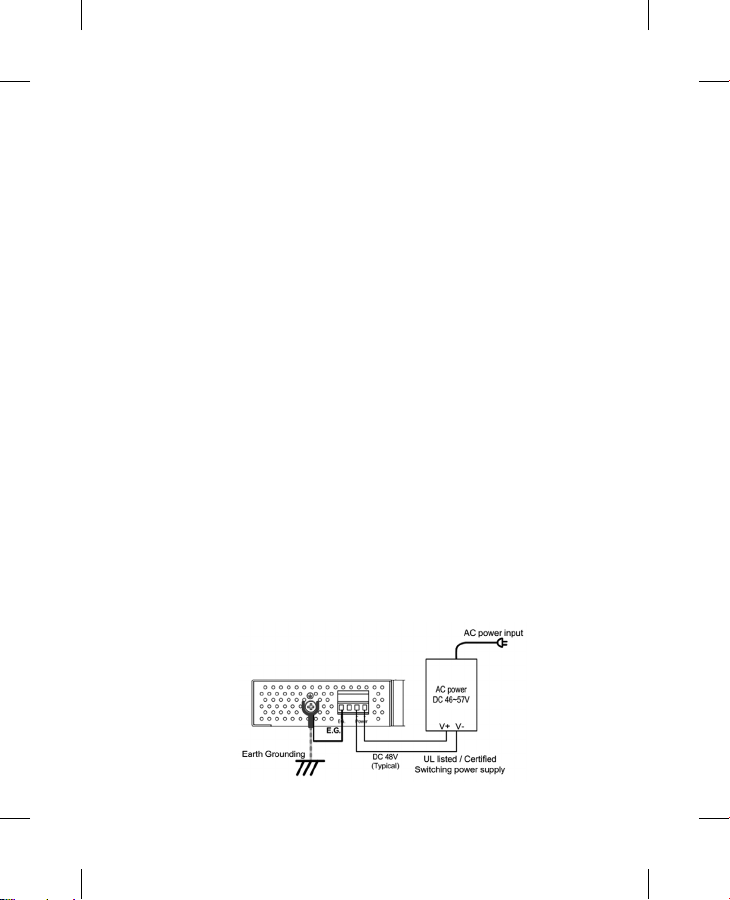
Powering the PII-2G
The PII-2G supports one 4-pin removable terminal block with wide power input – DC 46~57V,
one surge grounding connect. The wiring diagram of power connector with power supply as
displayed in the chart below.
Page 3
The E.G. pin must be connected with Earth Grounding Screw and which makes connection
to the Power System’s Earth Grounding. If the E.G. pin is not connected to Earth Grounding,
then the Surge / Spark protective function will not be enabled. Besides, the connection of E.G.
and Earth Grounding must remove before performing Hi-Pot or Insulation Testing. If not, the
Surge protection circuit will be damaged during the Hi-Pot / Insulation testing, and the testing
result will fail.
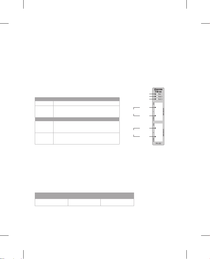
The Front Panel
The PII-2G supports 2-channels Gigabit high power connection,
and there are several LED to indicate the system power, PoE1
and PoE2. The data ow on each channel is shown individually.
LED Status
Pwr Green on: power i s applying
PoE
Port Description
PoE
Data In
Green on: PoE pow er is applying
Slow Blinkin g: PoE over current or cable sh ort
Green fast bli nking: over voltage or over temp erature
Connects to P D (WiFi AP, IP Camera)
Port trans mits Data and Power togethe r
Speed: 10/100/100 0Mbps connection
Connects to Et hernet Switch Device,
Port transmits data only
Speed: 10/100/100 0Mbps connection
Channel # 1
Channel # 2
Power LED
PoE LED
Data &
Power
Data
Data &
Power
Data
Power over Ethernet Connection
Each PoE channel supports 30W power budget with a compliance of IEEE 802.3af /
802.3at. If the PD device does not have power, please check PD’s powering method
whether it is in complies with IEEE 802.3af/at standard which has the same powering
mode as PII-2G.
If different pairs of the PD’s are used as feed in power, then the PoE connection will not be
constructed. As shown in the charts below the powering pair cables for you reference.
Model Powering c able pai r Note
PII-2G Alt ernative A 1,2,3,6 Data Pair powe ring
Note: If the PD can’t be powering by PII-2G, then it may not be fully compliant with the
IEEE802.3 PoE standard. It is recommended to use legacy power injector which feeds
power directly to the PD device.
Page 4
Einführung
Vielen Dank für den Kauf des PII-2G Power over Ethernet (PoE) Injektor. Der PII-2G ist
ein moderner und kostenefzienter Hochleistungs-PoE Injektor; Er versorgt das Powered
Device (PD) über die Ethernet RJ-45 Datenleitungs, gemäß den Power over Ethernet
Standards IEEE 802.3at und IEEE 802.3af. Er besitzt 2 PoE -Kanäle und ist besonders
für den drahtlosen Fernzugriff oder Videoüberwachungs- Anwendungen geeignet, bei
denen die Stromversorgung nur aufwendig oder gar nicht verlegt werden kann. Der PII-2G
Stromversorgungsmethode ist gemäss Alternative A nach IEEE 802.3at., d.h. den Strom wird
über die Datenleitungen des 4-paarigen UTP Kabels injiziert. In dieser Kurzanleitung (“Quick
Installation Guide”)wird gezeigt, wie die Verbindung zum PD Gerät gemacht wird, der PII-2G
mit Strom versorgt wird und wie der PII-2G installiert wird.
Packungsinhalt
Das Gerät wird mit den nachfolgenden Teilen geliefert:
4PII-2G
4Eine Kurzanleitung (Quick Installation Guide (QIG))
4Ein abnehmbarer 4-Pin Schraubklemmblock
Sollte ein Teil fehlen, kontaktieren Sie bitte Ihren lokalen Händler.
Stromversorgung des PII-2G
Der PII-2G bietet über den abnehmbaren 4-Pin Schraubklemmblock einen Weitbereich-
Spannungseingang von 46~57 VDC und einen Anschluss für die Masse. Die Verdrahtung
der Spannungsversorgung mit dem Klemmblock zeigt die unten abgebildete Skizze.
DE
Page 5

Der E.G. Pin muss mit Hilfe der Masse-Schraube fest mit der System-Masse (Erde)
verbunden werden. Wenn der E.G. Pin nicht mit der System-Masse verbunden ist, ist die
Schutzfunktion gegen Spannungsstoß / Funkenschlag nicht gegeben. Anmerkung: Die
Verbindung von E.G. und System Masse muss für Hi-Pot oder Isolations-Tests getrennt
werden. Wenn nicht, wird die Schutzfunktion durch den Hi-Pot / Isolations-Test beschädigt
und das Testergebnis negativ.
Die Frontseite
Der PII-2G bietet 2 PoE Injektor Kanäle mit mehreren LEDs zur
Anzeige der Spannungsversorgung, PoE1 und PoE2. Der Datenuss
ist pro Kanal individuell.
LED Status
Pwr Grün an: Strom eingeschaltet.
Grün an: PoE Str om eingeschaltet
PoE
Grün langs am blinkend: PoE Stromüber schreitung oder Kurzs chluss
Grün schnell blinkend: PoE-Strom- oder Temperatur- über schreitung
Port Beschreibung
Verbunden mit PD ( WiFi AP, IP Kamera).
PoE
Port über trägt Daten und Strom ge meinsam.
Geschwindigkeit: 10/100/1000Mbps Verbindung
Verbunden mit Ethernet Gerät. Port überträgt nur Daten.
Data In
Geschwindigkeit: 10/100/1000Mbps Verbindung
Channel # 1
Channel # 2
Power LED
PoE LED
Data &
Power
Data
Data &
Power
Data
Power over Ethernet Verbindung
Jeder PoE Kanal unterstützt max. 30W Leistung entsprechend der Norm IEEE 802.3af
/ 802.3at. Wenn das PD Gerät keinen Strom erhält, prüfen Sie die Methode der
Stromversorgung und ob sie dem IEEE 802.3af/ at Standard entspricht und ob das PD
Gerät die gleichen Stromleitungspaare benutzt wie der PII-2G.
Wenn das PD andere Leitungspaare zur Stromversorgung nutzt, wird die PoE-Verbindung
nicht hergestellt. Hier sind die genutzten Datenpaare gelistet:
Model Powering c able pai r Note
PII-2G Alt ernative A 1,2,3,6 Datenleitungs- Paar überträgt den Strom
Beachte: Wenn das PD vom PII-2G nicht mit Strom versorgt werden kann, ist es vielleicht
nicht voll kompatibel zum IEEE802.3 PoE Standard. In dem Fall wird eine konventionelle
direkte Spannungsversorgung empfohlen.
Page 6

Introduction
Le convertisseur PII-2G Power over Ethernet (PoE) Injecteur, propose une puissance élevée
au niveau des injecteurs PoE, l’alimentation s'applique sur les paires de données Ethernet
RJ-45 de rechange pour alimenter le périphérique (PD),
Il est conforme à la norme IEEE 802.3af et IEEE 802.3af Power over Ethernet standards. Il
dispose de 2 canaux d'injecteurs de type PoE et est très approprié pour les accès réseau
sans fil, les applications de vidéo surveillance où le raccordement et le câblage des
alimentations sont difciles.
Le type d'alimentation Alternative A, spécifié dans la norme IEEE 802.3at, est employé
par le PII-2G, ça veut dire que l'alimentation est injecté à travers des paires de données.
Dans ce guide d'installation rapide, il vous est proposé de réaliser une connexion avec un
périhérique (PD), son alimentation avec le PII-2G, et l’installation du PII-2G.
Contenu de la boite
Le pack contient les éléments suivants :
4PII-2G
4Un guide d'installation rapide
4Un connecteur bornier amovible à 4 broches
Si un élément est manquant, contacté votre représentant commercial local.
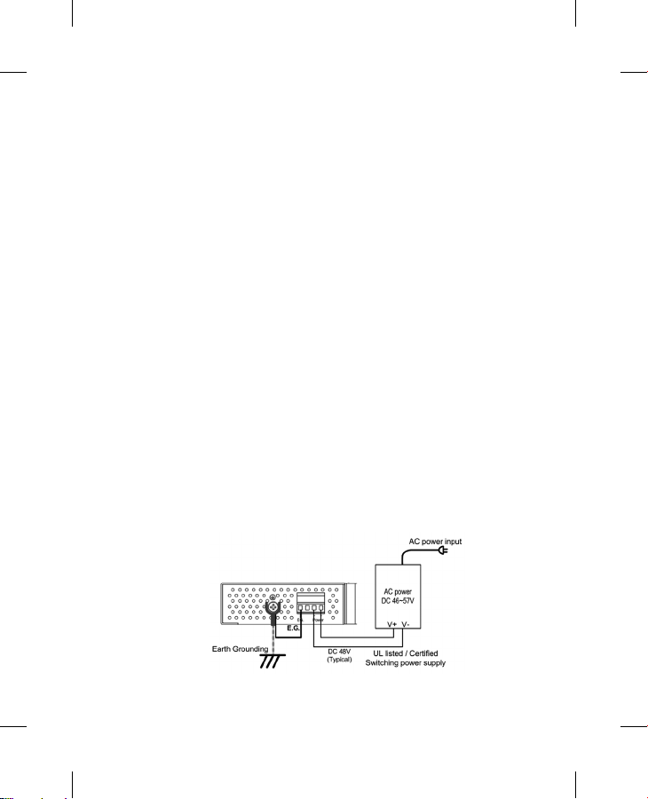
Alimentation du PII-2G
Le PII-2G est raccordé à l’alimentation par un bornier amovible à 4 broches avec une plage
d’entrée en tension - DC 46 ~ 57V. Une borne de terre est aussi disponible pour la protection
contre les surtensions. Le schéma de câblage du connecteur d'alimentation est présenté ci-
dessous.
FR
Page 7

Il faut faire attention au bon raccordement de la vis de masse du boitier E.G et à la mise à la
terre du système. Si cette connexion n’est pas correcte, la fonction de protection contre les
surcharges ne sera pas activée. En outre, la connexion EX et de mise à la terre doivent être
enlevées avant de procéder à un test d’isolement. Sinon, le circuit de protection contre les
surtensions pourrait être endommagé pendant cet essai d'isolement et le résultat négatif.
Face Avant
Le PII-2G prend en charge 2 canaux d'injecteurs PoE, et il y a plusieurs
LED pour indiquer l’alimentation de chaque système, PoE1 et PoE2. Le
débit de chaque canal de données est individuel.
LED Status
Pwr Green on: power i s applying
PoE
Port Description
PoE
Data In
Green on: PoE pow er is applying
Slow Blinkin g: PoE over current or cable sh ort
Green fast bli nking: over voltage or over temp erature
Connects to P D (WiFi AP, IP Camera)
Port trans mits Data and Power togethe r
Speed: 10/100/100 0Mbps connection
Connects to Et hernet Switch Device,
Port transmits data only
Speed: 10/100/100 0Mbps connection
Channel # 1
Channel # 2
Power LED
PoE LED
Data &
Power
Data
Data &
Power
Data
Power over Ethernet Connexion
Chaque canal PoE supporte une puissance de 30W, et est conforme à la norme IEEE
802.3af / 802.3at.
Si le périphérique device (PD) ne peut pas être mis sous tension, vérier si l’alimentation
utilisée est conforme à la norme IEEE 802.3af et si les mêmes paires que le PII-2G sont
utilisées.
Si le PD utilise différentes paires d'alimentation pour la puissance, la connexion PoE ne
sera pas possible. Voir les paires utilisées pour l’alimentation ci-dessous:
Model Powering c able pai r Note
PII-2G Alt ernative A 1,2,3,6 Data Pair powe ring
Remarque: Si le PD ne peut pas être alimenté par le PII-2G, alors il ne peut pas être
entièrement conforme à la norme PoE IEEE 802.3. Il est dans ce cas recommandé d’utiliser
une alimentation indépendante plus puissante pour alimenter l’injecteur directement.
Page 8

Introducción
Gracias por adquirir el inyector Power Over Ethernet (PoE) PII-2G. Se trata de un inyector
avanzado y económico de dos canales Gigabit que alimenta a los dispositivos PoE (PDs) de
alta potencia mediante los cables RJ45 de datos dicho conector, siguiendo los estándares
de grado industrial IEEE 802.3at y IEEE802.3af. Es una solución ideal para actualizar
sistemas Gigabit Ethernet a Gigabit PoE para su uso en entornos industriales donde no se
dispone de alimentación, como por ejemplo puntos de acceso wireless o de video-vigilancia.
El método de alimentación del PII-2G concuerda con la Alternative A, signica que el PII-2G
inyecta alimentación en los 4 pares de los cables UTP. Según lo especicado en el estandar
IEEE 802.3at y su denición ocial - Alternative A (alimentación en los cables de datos).
La guía de instalación rápida le ayudará a realizar las conexiones con los dispositivos PD y
le mostrará cómo alimentar e instalar el PII-2G.
Contenido del Embalaje
En el embalaje se incluyen los siguientes artículos:
4PII-2G
4Guía de instalación rápida (QIG)
4Conector extraíble de 4 pins
Si falta alguno de los componentes o tiene alguna consulta, por favor contacte con su
representante local.
Alimentando el PII-2G
El PII-2G soporta un amplio rango de tensión de entrada DC (46 a 57V) suministrados a
través de un terminal extraíble de 4 pins, aparte de una conexión adicional de masa. La
gura siguiente muestra el conexionado del PII-2G:
SP
Page 9

El pin E.G. debe conectarse con el terminal de tierra y a su vez con la tierra del sistema. Si
el pin E.G. no se conecta la protección contra transitorios no será efectiva. Por otra parte la
conexión E.G. debe ser retirada en el caso de pruebas de rigidez o de aislamiento. En caso
contrario el circuito de protección resultará averiado y el test fallido.
Panel Frontal
El PII-2G dispone de dos puertos Gigabit con PoE de alta
potencia. Existen varios indicadores led para mostrar el estado
de la alimentación, PoE1 y PoE2. El ujo de datos se muestra de
Channel # 1
Channel # 2
Power LED
PoE LED
Data &
Power
Data
Data &
Power
Data
forma independiente en cada canal.
LED Estado
Pwr Verde ON: El sistem a está alimentado
Verde ON: Se aplic a PoE
PoE
Intermitenc ia lenta: Sobrecorr iente PoE o cable cort icircuitado
Intermitencia rápida: sobrevoltaje o temperatura excesiva
Puerto Descripción
Conexión a PD ( Wifi AP, Cámara IP,..). El p uerto transmite
PoE
datos y aliment ación simultáneos.
Veloci dad: 10/100/100 0Mbps
Conexión al sw itch Ethernet, sólo se tr ansmiten datos.
Data In
Veloci dad: 10/100/100 0Mbps
Conexión Power over Ethernet
Cada canal PoE soporta hasta 30W bajo normativa IEEE 802.3af / 802.3at. Si el
dispositivo (PD) no recibe alimentación, por favor revise si cumple las especicaciones
IEEE 802.3af / 802.3at y si funciona de la misma forma que el PII-2G. Si se utilizan
distintos cables en el PD que los utilizados en el inyector PoE, la alimentación no se
establecerá. En la tabla siguiente se muestran los cables utilizados en cada modelo:
Modelo Cables con alimentación Nota
PII-2G Alt ernative A 1,2,3,6 Alimenta ción en cabl es de datos
Nota: Si el dispositivo (PD) no puede ser alimentado por el PII-2G, puede que no sea
totalmente compatible con el estándar IEEE 802.3. Se recomienda utilizar en este caso
los sistemas de inyección más antiguos que alimentan directamente al dispositivo.
Page 10

Page 11

Page 12

Westermo • SE-640 40 Stora Sundby, Sweden
Tel +46 16 42 80 00 Fax +46 16 42 80 01
E-mail: info@westermo.com
www.westermo.com
Sales Units
Westermo Data Communications
China
sales.cn@westermo.com
www.cn.westermo.com
France
infos@westermo.fr
www.westermo.fr
Germany
info@westermo.de
www.westermo.de
For complete contact information, please visit our website at www.westermo.com/contact
North America
info@westermo.com
www.westermo.com
Singapore
sales@westermo.com.sg
www.westermo.com
Sweden
info.sverige@westermo.se
www.westermo.se
or scan the QR code with your mobile phone.
United Kingdom
sales@westermo.co.uk
www.westermo.co.u
Other Offices
k
CPQ017N5310000 V1.0
2014-11 Westermo Teleindustri AB, Sweden – A Beijer Electronics Group Company
 Loading...