

Page 1
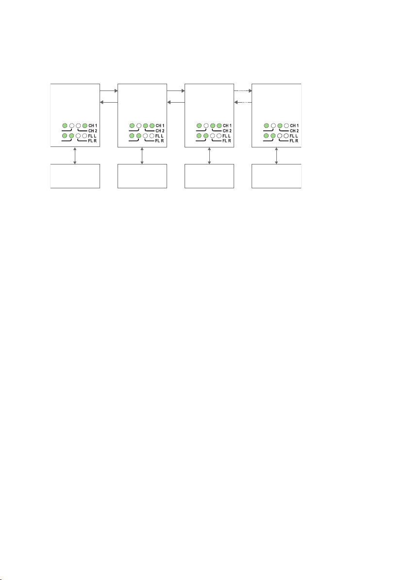
Management Guide
6651-2255
Westermo
ODW-730-F2
Westermo Teleindustri AB
©
Industrial Converter
RS-485 to Fibre Optic Link.
Repeater, line and redundant ring
www.westermo.com
Page 2

2
6651-2255
Content
Multidrop, Y-mode configuration ........................................................................................................................................... 3
Prepare the fibre optical network ......................................................................................................................................... 3
Data transport in multidrop, Y-mode configuration ........................................................................................... 4
Multidrop, V-mode configuration ........................................................................................................................................... 5
Prepare the fibre optical network ......................................................................................................................................... 5
Data transport in multidrop, V-mode configuration ........................................................................................... 6
Multidrop dual channel, Y-mode configuration ................................................................................................. 7
Prepare the fibre optical network ................................................................................................................................... 7–8
Data transport in multidrop, dual channel, Y-mode configuration ...................................................... 9
Multidrop, dual channel, V-mode configuration ............................................................................................ 10
Prepare the fibre optical network ............................................................................................................................ 10–11
Data transport in multidrop, dual channel, V-mode configuration ......................................... 12–13
Redundant ring, Y-mode configuration ...................................................................................................................... 14
Prepare the fibre optical network ...................................................................................................................................... 14
Data transport in redundant ring, Y-mode configuration ................................................................ 15–16
Redundant ring, V-mode configuration ..................................................................................................................... 17
Prepare the fibre optical network ............................................................................................................................ 17–18
Data transport in redundant ring, V-mode configuration ................................................................ 19–20
Redundant ring, dual channel, Y-mode configuration .......................................................................... 21
Prepare the fibre optical network ............................................................................................................................ 21–22
Data transport in redundant ring, dual channel, Y-mode configuration ........................... 23–25
Redundant ring, dual channel, V-mode configuration .......................................................................... 26
Prepare the fibre optical network ............................................................................................................................ 26–27
Data transport in redundant ring, dual channel, V-mode configuration ........................... 28–30
LED indication during optical link failure ............................................................................................................. 31
Calculating system processing delay ............................................................................................................................ 32
Reconfiguration time under faulty condition ................................................................................................. 33
About the interfaces ............................................................................................................................................................................ 34
Power terminal ......................................................................................................................................................................................... 34
Optical fibre interfaces .................................................................................................................................................................... 34
RS-485 interface ...................................................................................................................................................................................... 34
Status port ..................................................................................................................................................................................................... 34
Page 3
3
6651-2255
Multidrop, Y-mode configuration
RX2
TX2
End Unit
S2: 3 ON S2: 3 OFF S2: 3 OFF
Device 1
Communicates
with all other devices
Device 2
Communicates
with all other devices
Device 3
Communicates
with all other devices
Device n
Communicates
with all other devices
TX1
RX1
RX2
TX2
End Unit
S2: 3 ON
TX1
RX1
RX2
TX2
RS-485 RS-485 RS-485
Fibre
pair
Fibre
pair
Fibre
pair
RS-485
TX1
RX1
RX2
TX2
TX1
RX1
PWR
FP
TD
RD
PWR
FP
TD
RD
PWR
FP
TD
RD
PWR
FP
TD
RD
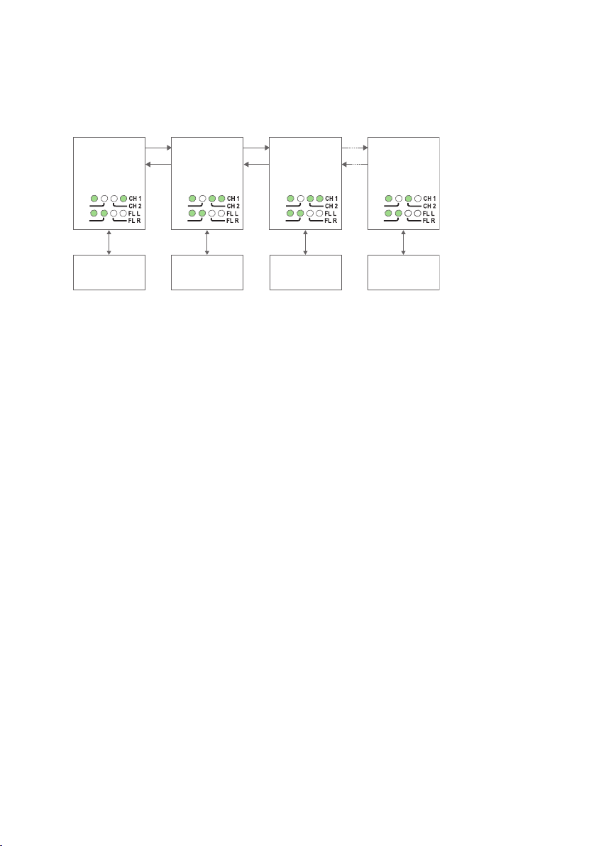
In Y-mode mode an ODW-730 network will behave as a 2-wire bus. I.e. all communication devices will “hear” the data sent out by other communication devices.
Prepare the fibre optical network
• Configure all ODW-730 units for the correct speed and data format using DIPswitches S1:1 – S1:7.
• Select RS-485 2 wire and 4-wire mode using DIP-switch S2:1 (OFF = 2-wire,
ON = 4-wire).
• Enable the RS-485 termination / fail-safe if required using DIP-switches S3:1 – S3:4
(S3:1 and S3:2 = 4-wire termination, S3:3 and S3:4 = 2-wire termination).
• The first and last ODW-730 units must be configured as Multidrop end units by setting DIP-switch S2:3 to the ON position. (End units only have one fibre pair each and
must know that this is a fact)
• Set DIP-switch and S2:6 as desired. See page 34 “Status port” for more information.
• Verify that DIP-switches S1:8, S2:2, S2:4, S2:5 and S2:8 are set in the OFF position.
• Connect the fibre pairs between the units. Always connect CH 1 from one unit to CH
2 on the next unit as shown in the picture above.
• Connect the power supply to all units and verify that all fibre links become active.
(CH 1 and CH 2 LED’s are on, FL L and FL R LED’s are off).
• Connect the communication devices to the corresponding ODW-730 unit.
• The network is now up and running.
Note: In an ODW-730 fibre optic network there will be some additional processing
delays that do not exist in an electrical bus. It is possible that the application must be
adjusted to accommodate these delays if using many ODW-730 units in a large network.
See page 32 “Calculating system processing delay” for more information on how to
determine the overall system delay time.
Page 4
4
6651-2255
Data transport in multidrop, Y-mode configuration
RX2
TX2
Device 1
Sending
Device 2
Receiving
Device 3
Receiving
Device n
Receiving
TX1
RX1
RX2
TX2
TX1
RX1
RX2
TX2
RS-485 RS-485 RS-485
Fibre
pair
Fibre
pair
Fibre
pair
RS-485
TX1
RX1
RX2
TX2
TX1
RX1
PWR
FP
TD
RD
PWR
FP
TD
RD
PWR
FP
TD
RD
PWR
FP
TD
RD
RX2
TX2
Device 1
Receiving
Device 2
Receiving
Device 3
Sending
Device n
Receiving
TX1
RX1
RX2
TX2
TX1
RX1
RX2
TX2
RS-485 RS-485 RS-485
Fibre
pair
Fibre
pair
Fibre
pair
RS-485
TX1
RX1
RX2
TX2
TX1
RX1
PWR
FP
TD
RD
PWR
FP
TD
RD
PWR
FP
TD
RD
PWR
FP
TD
RD
Data from comminication device 1 is received at the ODW-730 RS-485 port (as indicated by the TD LED), data bits are retimed according to the preset rate and sent out
on the optical fibre TX1. The next ODW-730 unit receives data at optical fibre RX2
(as indicated by the RD LED), and data is sent out on the RS-485 port. Data is also
repeated out on TX1 on to the next ODW-730 unit.
Data from some other communication device, for example device 3, is processed in the
same way and sent out on both optical fibres TX1 and TX2.
Page 5
5
6651-2255
Multidrop, V-mode configuration
RX2
TX2
End Unit
S1: 8 ON
S2: 3 ON
S1: 8 ON
S2: 3 OFF
S1: 8 ON
S2: 3 OFF
End Unit
S1: 8 ON
S2: 3 ON
Device 1
Communicates
with devices 2 througt n
Device 2
Communicates
with device 1 only
Device 3
Communicates
with device 1 only
Device n
Communicates
with device 1 only
TX1
RX1
RX2
TX2
TX1
RX1
RX2
TX2
RS-485 RS-485 RS-485
Fibre
pair
Fibre
pair
Fibre
pair
RS-485
TX1
RX1
RX2
TX2
TX1
RX1
PWR
FP
TD
RD
PWR
FP
TD
RD
PWR
FP
TD
RD
PWR
FP
TD
RD
In V-mode an ODW-730 network will behave as a 4-wire bus. Where the first ODW-730
(leftmost in the picture below) will able to communicate in full duplex with any other
unit, but other units are incapable of communicating with each other.
Prepare the fibre optical network
• Configure all ODW-730 units for the correct speed and data format using
DIP-switches S1:1 – S1:7.
• Select RS-485 2 wire and 4-wire mode using DIP-switch S2:1 (OFF = 2-wire,
ON = 4-wire).
• Enable the RS-485 termination / fail-safe if required using DIP-switches S3:1 – S3:4
(S3:1 and S3:2 = 4-wire termination, S3:3 and S3:4 = 2-wire termination)
• Set DIP-switch S1:8 in the ON position (V-mode) on all ODW-730 units.
• The first and last ODW-730 units must be configured as Multidrop end units by
setting DIP-switch S2:3 to the ON position. (End units only have one fibre pair
each and must know that this is a fact)
• Set DIP-switch S2:6 as desired. See page 34 “Status port” for more information.
• Verify that DIP-switches S2:2, S2:4, S2:5 and S2:8 are set in the OFF position.
• Connect the fibre pairs between the units. Always connect CH 1 from one unit to
CH 2 on the next unit as shown in the picture above.
• Connect the power supply to all units and verify that all fibre links become active.
(CH 1 and CH 2 LED’s are on, FL L and FL R LED’s are off).
• Connect the communication devices to the corresponding ODW-730 unit.
• The network is now up and running.
Note: In an ODW-730 fibre optic network there will be some additional processing
delays that do not exist in an electrical bus. It is possible that the application must be
adjusted to accommodate these delays if using many ODW-730 units in a large network.
See page 32 “Calculating system processing delay” for more information on how to
determine the overall system delay time.
Page 6
6
6651-2255
Data transport in multidrop, V-mode configuration
RX2
TX2
Device 1
Sending
Device 2
Receiving
Device 3
Receiving
Device n
Receiving
TX1
RX1
RX2
TX2
TX1
RX1
RX2
TX2
RS-485 RS-485 RS-485
Fibre
pair
Fibre
pair
Fibre
pair
RS-485
TX1
RX1
RX2
TX2
TX1
RX1
PWR
FP
TD
RD
PWR
FP
TD
RD
PWR
FP
TD
RD
PWR
FP
TD
RD
RX2
TX2
Device 1
Receiving
Device 2
Not sending or
receiving any data
Device 3
Sending
Device n
Not sending or
receiving any data
TX1
RX1
RX2
TX2
TX1
RX1
RX2
TX2
RS-485 RS-485 RS-485
Fibre
pair
Fibre
pair
Fibre
pair
RS-485
TX1
RX1
RX2
TX2
TX1
RX1
PWR
FP
TD
RD
PWR
FP
TD
RD
PWR
FP
TD
RD
PWR
FP
TD
RD
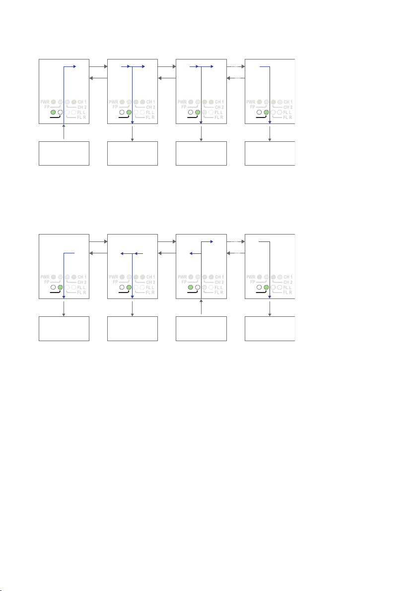
Data from comminication device 1 is received at the ODW-730 RS-485 port (as indicated by the TD LED), data bits are retimed according to the preset rate and sent out
on the optical fibre TX1. The next ODW-730 unit receives data at optical fibre RX2
(as indicated by the RD LED), and data is sent out on the RS-485 port. Data is also
repeated out on TX1 on to the next ODW-730 unit.
Data from some other communication device, for example device 3, is processed in the
same way and sent out on optical fibre TX2. Intermediate ODW-730 units will receive
this data at optical fibre RX1 and repeat it out on optical fibre TX2. But, intermediate
units will not send any data received at RX1 on to the RS-485 port. Only the first
ODW-730 (leftmost in the picture above) will have incomming data from optical fibre
RX1 sent out on the RS-485 port.
I.e. the first ODW-730 is able to communicate in full duplex with any other unit, but
other units are incapable of communicating with each other.
Page 7
7
6651-2255
Multidrop dual channel, Y-mode configuration
RX2
TX2
End Unit
S2: 3 ON
S2: 4 OFF
S2: 3 OFF
S2: 4 ON
S2: 3 OFF
S2: 4 OFF
End Unit
S1: 3 ON
S2: 4 ON
Device 1
Communicates
with device 3 on the
primary data channel
Device 2
Communicates
with device 4 on the
secondary data channel
Device 3
Communicates
with device 1 on the
primary data channel
Device 4
Communicates
with device 2 on the
secondary data channel
TX1
RX1
RX2
TX2
TX1
RX1
RX2
TX2
RS-485 RS-485 RS-485
Fibre
pair
Fibre
pair
Fibre
pair
RS-485
TX1
RX1
RX2
TX2
TX1
RX1
PWR
FP
TD
RD
PWR
FP
TD
RD
PWR
FP
TD
RD
PWR
FP
TD
RD
In dual channel mode it is possible to use two separate data streams in a single ODW730 network. However, all ODW-730’s must be set to the same speed and data format.
This, of course, limits the number of possible applications for a dual channel network.
In Y-mode mode an ODW-730 network will behave as a 2-wire bus. I.e. all communication devices will “hear” the data sent out by other communication devices.
Prepare the fibre optical network
• Configure all ODW-730 units for the correct speed and data format using DIPswitches S1:1 – S1:7. Again, notice that all ODW-730’s must be set to the same
speed and data format.
• Select RS-485 2 wire and 4-wire mode using DIP-switch S2:1 (OFF = 2-wire,
ON = 4-wire).
• Enable the RS-485 termination / fail-safe if required using DIP-switches S3:1 – S3:4
(S3:1 and S3:2 = 4-wire termination, S3:3 and S3:4 = 2-wire termination)
• The first and last ODW-730 units must be configured as Multidrop end units by
setting DIP-switch S2:3 to the ON position (End units only have one fibre pair
each and must know that this is a fact).
• All ODW-730 units that are to use the primary data channel (“blue” units in the
picture above) must have DIP-switch S2:4 set to the OFF position. Units that are
to use the secondary data channel (“orange” units in the picture above) must have
DIP-switch S2:4 set to the ON position.
• Set DIP-switch S2:6 as desired. See page 34 “Status port” for more information.
• Verify that DIP-switches S1:8, S2:1, S2:2, S2:5 and S2:8 are set in the OFF position.
• Connect the fibre pairs between the units. Always connect CH 1 from one unit to
CH 2 on the next unit as shown in the picture above.
• Connect the power supply to all units and verify that all fibre links become active.
(CH 1 and CH 2 LED’s are on, FL L and FL R LED’s are off).
• Connect the communication devices to the corresponding ODW-730 unit.
• The network is now up and running.
Page 8

8
6651-2255
Note: In an ODW-730 fibre optic network there will be some additional processing
delays that do not exist in an electrical bus. It is possible that the application must be
adjusted to accommodate these delays if using many ODW-730 units in a large network.
See page 32 “Calculating system processing delay” for more information on how to
determine the overall system delay time.
Page 9
9
6651-2255
Data transport in multidrop, dual channel, Y-mode configuration
RX2
TX2
Device 1
Sending data to
device 3 on the
primary channel
Device 2
Sending data to
device 4 on the
secondary channel
Device 3
Receiving data from
device 1 on the
primary channel
Device 4
Receiving data from
device 4 on the
secondary channel
TX1
RX1
RX2
TX2
TX1
RX1
RX2
TX2
RS-485 RS-485 RS-485
Fibre
pair
Fibre
pair
Fibre
pair
RS-485
TX1
RX1
RX2
TX2
TX1
RX1
PWR
FP
TD
RD
PWR
FP
TD
RD
PWR
FP
TD
RD
PWR
FP
TD
RD
RX2
TX2
Device 1
Receiving data from
device 3 on the
primary channel
Device 2
Receiving data from
device 4 on the
secondary channel
Device 3
Sending data to
device 1 on the
primary channel
Device 4
Sending data to
device 2 on the
secondary channel
TX1
RX1
RX2
TX2
TX1
RX1
RX2
TX2
RS-485 RS-485 RS-485
Fibre
pair
Fibre
pair
Fibre
pair
RS-485
TX1
RX1
RX2
TX2
TX1
RX1
PWR
FP
TD
RD
PWR
FP
TD
RD
PWR
FP
TD
RD
PWR
FP
TD
RD
The first ODW-730 unit recieives data from communications device 1 on the RS-485
port and sends it out on optical fibre TX1 using the primary data channel.
The second ODW-730 unit receives primary channel data on optical fibre RX2. Primary
channel data is repeated out on optical fibre TX1. The second ODW-730 unit also
receives data from communications device 2 on the RS-485 port. The RS-485 data is sent
out on both optical fibres TX1 and TX2 using the secondary data channel.
The third ODW-730 unit receives both primary and secondary channel data on optical
fibre RX2. Both primary and secondary data are repeated out on optical fibre TX1, but
only the primary channel data is sent out on the RS-485 port.
The fourth ODW-730 unit receives both primary and secondary channel data on optical
fibre RX2, but only the secondary channel data is sent out on the RS-485 port.
The fourth ODW-730 unit recieives data from communications device 4 on the RS-485
port and sends it out on optical fibre TX2 using the secondary data channel.
The third ODW-730 unit receives secondary channel data on optical fibre RX1.
Secondary channel data is repeated out on optical fibre TX2. The third ODW-730 unit
also receives data from communications device 3 on the RS-485 port. The RS-485 data is
sent out on both optical fibres TX1 and TX2 using the primary data channel.
The second ODW-730 unit receives both primary and secondary channel data on optical
fibre RX1. Both primary and secondary data are repeated out on optical fibre TX2, but
only the secondary channel data is sent out on the RS-485 port.
The first ODW-730 unit receives both primary and secondary channel data on optical
fibre RX1, but only the primary channel data is sent out on the RS-485 port.
Page 10
10
6651-2255
Multidrop, dual channel, V-mode configuration
RX2
TX2
Primary – End Unit
S1: 8 ON
S2: 3 ON
S2: 4 OFF
S1: 8 OFF
S2: 3 OFF
S2: 4 ON
S1: 8 ON
S2: 3 OFF
S2: 4 OFF
End Unit
S1: 8 ON
S2: 3 ON
S2: 4 ON
Device 1
Communicates
with device 3 and 4 on
the primary data channel
Device 2
Communicates
with device 5 on the
secondary data channel
Device 3
Communicates
with device 1 on the
primary data channel
Device 5
Communicates
with device 2 on the
secondary data channel
TX1
RX1
RX2
TX2
TX1
RX1
RX2
TX2
RS-485 RS-485 RS-485
Fibre
pair
Fibre
pair
Fibre
pair
RS-485
TX1
RX1
RX2
TX2
TX1
RX1
PWR
FP
TD
RD
PWR
FP
TD
RD
PWR
FP
TD
RD
S1: 8 ON
S2: 3 OFF
S2: 4 OFF
Device 4
Communicates
with device 1 on the
primary data channel
RS-485
Fibre
pair
RX2
TX2
TX1
RX1
PWR
FP
TD
RD
PWR
FP
TD
RD
In dual channel mode it is possible to use two separate data streams in a single ODW730 network. However, all ODW-730’s must be set to the same speed and data format.
This, of course, limits the number of possible applications for a dual channel network.
In V-mode an ODW-730 network will behave as a 4-wire bus. Where the first ODW-730
(leftmost in the picture below) will able to communicate in full duplex with any other
unit, but other units are incapable of communicating with each other.
Prepare the fibre optical network
• Configure all ODW-730 units for the correct speed and data format using DIPswitches S1:1 – S1:7. Again, notice that all ODW-730’s must be set to the same speed
and data format.
• Select RS-485 2 wire and 4-wire mode using DIP-switch S2:1 (OFF = 2-wire,
ON = 4-wire).
• Enable the RS-485 termination / fail-safe if required using DIP-switches S3:1 – S3:4
(S3:1 and S3:2 = 4-wire termination, S3:3 and S3:4 = 2-wire termination)
• The first and last ODW-730 units must be configured as Multidrop end units by
setting DIP-switch S2:3 to the ON position (End units only have one fibre pair
each and must know that this is a fact).
• All ODW-730 units that are to use the primary data channel (“blue” units in the
picture above) must have DIP-switch S2:4 set to the OFF position. Units that are
to use the secondary data channel (“orange” units in the picture above) must have
DIP-switch S2:4 set to the ON position.
• The first ODW-730 unit using the secondary data channel (second from left in
• Set DIP-switch S1:8 in the ON position (V-mode) on all other ODW-730 units.
• Set DIP-switch S2:6 as desired. See page 34 “Status port” for more information.
• Verify that DIP-switches S2:1, S2:2, S2:5 and S2:8 are set in the OFF position.
the picture above) must have DIP-switch S1:8 set to the OFF position (Y-mode).
The reason for this is that the data will be sent in the wrong direction if this unit
is also set for V-mode.
Page 11

11
6651-2255
• Connect the fibre pairs between the units. Always connect CH 1 from one unit to
CH 2 on the next unit as shown in the picture above.
• Connect the power supply to all units and verify that all fibre links become active.
(CH 1 and CH 2 LED’s are on, FL L and FL R LED’s are off).
• Connect the communication devices to the corresponding ODW-730 unit.
• The network is now up and running.
Note: In an ODW-730 fibre optic network there will be some additional processing
delays that do not exist in an electrical bus. It is possible that the application must be
adjusted to accommodate these delays if using many ODW-730 units in a large network.
See page 32 “Calculating system processing delay” for more information on how to
determine the overall system delay time.
Page 12

12
6651-2255
Data transport in multidrop, dual channel, V-mode configuration
RX2
TX2
Device 1
Sending data to
device 3 and 4 on the
primary channel
Device 2
Sending data to
device 5 on the
secondary channel
Device 3
Receiving data from
device 1 on the
primary channel
Device 5
Receiving data from
device 2 on the
secondary channel
TX1
RX1
RX2
TX2
TX1
RX1
RX2
TX2
RS-485 RS-485 RS-485
Fibre
pair
Fibre
pair
Fibre
pair
RS-485
TX1
RX1
RX2
TX2
TX1
RX1
PWR
FP
TD
RD
PWR
FP
TD
RD
PWR
FP
TD
RD
PWR
FP
TD
RD
Device 4
Receiving data from
device 1 on the
primary channel
RS-485
Fibre
pair
RX2
TX2
TX1
RX1
PWR
FP
TD
RD
The first ODW-730 unit recieives data from communications device 1 on the RS-485
port and sends it out on optical fibre TX1 using the primary data channel.
The second ODW-730 unit receives primary channel data on optical fibre RX2. Primary
channel data is repeated out on optical fibre TX1. The second ODW-730 unit also
receives data from communications device 2 on the RS-485 port. The RS-485 data is sent
out on optical fibre TX1 using the secondary data channel.
The third and fourth ODW-730 units receive both primary and secondary channel data
on optical fibre RX2. Both primary and secondary data are repeated out on optical fibre
TX1, but only the primary channel data is sent out on the RS-485 port.
The fifth ODW-730 unit receives both primary and secondary channel data on optical
fibre RX2, but only the secondary channel data is sent out on the RS-485 port.
Page 13

13
6651-2255
RX2
TX2
Device 1
Receiving data from
device 4 on the
primary channel
Device 2
Receiving data from
device 5 on the
secondary channel
Device 3
Not sending
or receiving any data
Device 5
Sending data to
device 2 on the
secondary channel
TX1
RX1
RX2
TX2
TX1
RX1
RX2
TX2
RS-485 RS-485 RS-485
Fibre
pair
Fibre
pair
Fibre
pair
RS-485
TX1
RX1
RX2
TX2
TX1
RX1
PWR
FP
TD
RD
PWR
FP
TD
RD
PWR
FP
TD
RD
PWR
FP
TD
RD
Device 4
Sending data to
device 1 on the
primary channel
RS-485
Fibre
pair
RX2
TX2
TX1
RX1
PWR
FP
TD
RD
The fifth ODW-730 unit recieives data from communications device 5 on the RS-485
port and sends it out on optical fibre TX2 using the secondary data channel.
The fourth ODW-730 unit receives secondary channel data on optical fibre RX1.
Secondary channel data is repeated out on optical fibre TX2. The fourth ODW-730 unit
also receives data from communications device 4 on the RS-485 port. The RS-485 data is
sent out on optical fibre TX2 using the primary data channel.
The third ODW-730 unit receives both primary and secondary channel data on optical
fibre RX1. Both primary and secondary data are repeated out on optical fibre TX2. None
of the data is sent out on the RS-485 port.
The second ODW-730 unit receives both primary and secondary channel data on optical
fibre RX1. Both primary and secondary data are repeated out on optical fibre TX2, but
only the secondary channel data is sent out on the RS-485 port.
The first ODW-730 unit receives both primary and secondary channel data on optical
fibre RX1, but only the primary channel data is sent out on the RS-485 port.
Page 14

14
6651-2255
RX2
TX2
Focal point
S2:2 ON
S2:3 ON
Ring member
S2:2 ON
S2:3 OFF
Ring member
S2:2 ON
S2:3 OFF
Ring member
S2:2 ON
S2:3 OFF
Device 1
Communicates
with all other devices
Device 2
Communicates
with all other devices
Redundant fibre pair. Not used under normal operation.
Device 3
Communicates
with all other devices
Device n
Communicates
with all other devices
TX1
RX1
RX2
TX2
TX1
RX1
RX2
TX2
RS-485 RS-485 RS-485
Fibre
pair
Fibre
pair
Fibre
pair
Fibre
pair
used
to
carry
data
FP LED
is on to
indicate
focal point
RS-485
TX1
RX1
RX2
TX2
TX1
RX1
PWR
FP
TD
RD
PWR
FP
TD
RD
PWR
FP
TD
RD
PWR
FP
TD
RD
Redundant ring, Y-mode configuration
In a redundant ring an extra fibre pair is used. This extra fibre pair is used to carry data
if one of the other fibre pairs breaks. In Y-mode mode an ODW-730 network will behave
as a 2-wire bus. I.e. all communication devices will “hear” the data sent out by other
communication devices.
Prepare the fibre optical network
• Configure all ODW-730 units for the correct speed and data format using DIPswitches S1:1 – S1:7.
• Select RS-485 2 wire and 4-wire mode using DIP-switch S2:1 (OFF = 2-wire,
ON = 4-wire).
• Enable the RS-485 termination / fail-safe if required using DIP-switches S3:1 – S3:4
(S3:1 and S3:2 = 4-wire termination, S3:3 and S3:4 = 2-wire termination)
• Set DIP-switch S2:2 in the ON position (redundant ring) on all ODW-730 units.
• One, and only one, of the ODW-730 units must be configured as a Ring Focal Point by
setting DIP-switch S2:3 to the ON position. (The Ring Focal Point acts as a logical end
point in the optical fibre ring, thus forming a bus type of structure)
• Set DIP-switch S2:6 as desired. See page 34 “Status port” for more information.
• Verify that DIP-switches S1:8, S2:4, S2:5 and S2:8 are set in the OFF position.
• Connect the fibre pairs between the units. Always connect CH 1 from one unit to CH
2 on the next unit as shown in the picture above.
• Connect the power supply to all units and verify that all fibre links become active.
(CH 1 and CH 2 LED’s are on, FL L and FL R LED’s are off).
• Connect the communication devices to the corresponding ODW-730 unit.
• The network is now up and running.
Note: In an ODW-730 fibre optic network there will be some additional processing
delays that do not exist in an electrical bus. It is possible that the application must be
adjusted to accommodate these delays if using many ODW-730 units in a large network.
See page 32 “Calculating system processing delay” for more information on how to
determine the overall system delay time.
Page 15

15
6651-2255
Data transport in redundant ring, Y-mode configuration
RX2
TX2
Device 1
Sending
Device 2
Receiving
Device 3
Receiving
Device n
Receiving
TX1
RX1
RX2
TX2
TX1
RX1
RX2
TX2
RS-485 RS-485 RS-485
Fibre
pair
Fibre
pair
Fibre
pair
Focal point
RS-485
TX1
RX1
RX2
TX2
TX1
RX1
PWR
FP
TD
RD
PWR
FP
TD
RD
PWR
FP
TD
RD
PWR
FP
TD
RD
RX2
TX2
Device 1
Receiving
Device 2
Receiving
Device 3
Sending
Device 4
Receiving
TX1
RX1
RX2
TX2
TX1
RX1
RX2
TX2
RS-485 RS-485 RS-485
Fibre
pair
Fibre
pair
Fibre
pair
Focal point
RS-485
TX1
RX1
RX2
TX2
TX1
RX1
PWR
FP
TD
RD
PWR
FP
TD
RD
PWR
FP
TD
RD
PWR
FP
TD
RD
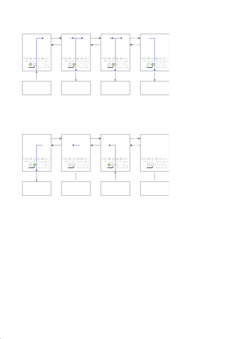
Data from comminication device 1 is received at the ODW-730 RS-485 port (as indicated by the TD LED), data bits are retimed according to the preset rate and sent out
on the optical fibre TX1. The next ODW-730 unit receives data at optical fibre RX2 (as
indicated by the RD LED), and data is sent out on the RS-485 port. Data is also repeated
out on TX1 on to the next ODW-730 unit.
Data from some other communication device, for example device 3, is processed in the
same way and sent out on both optical fibres TX1 and TX2. Notice that the Ring Focal
point never repeats incoming data.
Page 16

16
6651-2255
RX2
TX2
Device 1
Sending
Device 2
Receiving
Device 3
Reciving
Device 4
Receiving
TX1
RX1
RX2
TX2
TX1
RX1
RX2
TX2
RS-485 RS-485 RS-485
Fibre
pair
Faulty
segment
Fibre
pair
Focal point
RS-485
TX1
RX1
RX2
TX2
TX1
RX1
PWR
FP
TD
RD
PWR
FP
TD
RD
PWR
FP
TD
RD
PWR
FP
TD
RD
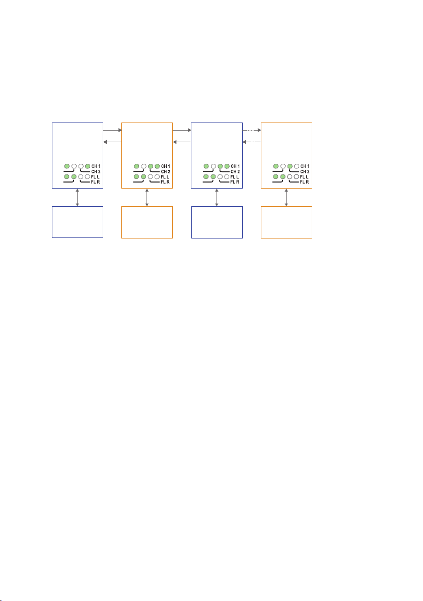
If an optical fibre segment fails, the ODW-730 Ring Focal Point will switch mode and
RX2
TX2
Device 1
Receiving
Device 2
Receiving
Device 3
Reciving
Device 4
Sending
TX1
RX1
RX2
TX2
TX1
RX1
RX2
TX2
RS-485 RS-485 RS-485
Fibre
pair
Faulty
segment
Fibre
pair
Focal point
RS-485
TX1
RX1
RX2
TX2
TX1
RX1
PWR
FP
TD
RD
PWR
FP
TD
RD
PWR
FP
TD
RD
PWR
FP
TD
RD
start sending out data on both optical fibre ports, TX1 and TX2, simultaneously.
The other ODW-730 units will continue to send data out on both optical fibres TX1
and TX2. Consequently, all communication devices will still be able to communicate with
each other. Notice that the Ring Focal Point is now repeating incoming data.
Page 17

17
6651-2255
RX2
TX2
Focal point
S1:8 ON
S2:2 ON
S2:3 ON
Ring member
S1:8 ON
S2:2 ON
S2:3 OFF
Ring member
S1:8 ON
S2:2 ON
S2:3 OFF
Ring member
S1:8 ON
S2:2 ON
S2:3 OFF
Device 1
Communicates
with all other devices
Device 2
Communicates
with device 1 only
Redundant fibre pair. Not used under normal operation.
Device 3
Communicates
with device 1 only
Device n
Communicates
with device 1 only
TX1
RX1
RX2
TX2
TX1
RX1
RX2
TX2
RS-485 RS-485 RS-485
Fibre
pair
Fibre
pair
Fibre
pair
Fibre
pair
used
to
carry
data
FP LED
is on to
indicate
focal point
RS-485
TX1
RX1
RX2
TX2
TX1
RX1
PWR
FP
TD
RD
PWR
FP
TD
RD
PWR
FP
TD
RD
PWR
FP
TD
RD
Redundant ring, V-mode configuration
In a redundant ring an extra fibre pair is used. This extra fibre pair is used to carry data
if one of the other fibre pairs breaks. In V-mode mode an ODW-730 network will behave
as a 4-wire bus. Where the first ODW-730 (leftmost in the picture below) will able to
communicate in full duplex with any other unit, but other units are incapable of communicating with each other.
Prepare the fibre optical network
• Configure all ODW-730 units for the correct speed and data format using DIPswitches S1:1 – S1:7.
• Select RS-485 2 wire and 4-wire mode using DIP-switch S2:1 (OFF = 2-wire,
ON = 4-wire).
• Enable the RS-485 termination / fail-safe if required using DIP-switches S3:1 – S3:4
(S3:1 and S3:2 = 4-wire termination, S3:3 and S3:4 = 2-wire termination)
• Set DIP-switch S1:8 in the ON position (V-mode) on all ODW-730 units.
• Set DIP-switch S2:2 in the ON position (redundant ring) on all ODW-730 units.
• One, and only one, of the ODW-730 units must be configured as a Ring Focal Point by
setting DIP-switch S2:3 to the ON position. (The Ring Focal Point acts as a logical end
point in the optical fibre ring, thus forming a bus type of structure)
• Set DIP-switch S2:6 as desired. See page 34 “Status port” for more information.
• Verify that DIP-switches S2:4, S2:5 and S2:8 are set in the OFF position.
• Connect the fibre pairs between the units. Always connect CH 1 from one unit to
CH 2 on the next unit as shown in the picture above.
• Connect the power supply to all units and verify that all fibre links become active.
(CH 1 and CH 2 LED’s are on, FL L and FL R LED’s are off).
• Connect the communication devices to the corresponding ODW-730 unit.
• The network is now up and running.
Note: In an ODW-730 fibre optic network there will be some additional processing
delays that do not exist in an electrical bus. It is possible that the application must be
Page 18

18
6651-2255
adjusted to accommodate these delays if using many ODW-730 units in a large network.
See page 32 “Calculating system processing delay” for more information on how to
determine the overall system delay time.
Page 19

19
6651-2255
Data transport in redundant ring, V-mode configuration
RX2
TX2
Device 1
Sending
Device 2
Receiving
Device 3
Receiving
Device n
Receiving
TX1
RX1
RX2
TX2
TX1
RX1
RX2
TX2
RS-485 RS-485 RS-485
Fibre
pair
Fibre
pair
Fibre
pair
Focal point
RS-485
TX1
RX1
RX2
TX2
TX1
RX1
PWR
FP
TD
RD
PWR
FP
TD
RD
PWR
FP
TD
RD
PWR
FP
TD
RD
RX2
TX2
Device 1
Receiving
Device 2
Not sending or
receiving any data
Device 3
Sending
Device n
Not sending or
receiving any data
TX1
RX1
RX2
TX2
TX1
RX1
RX2
TX2
RS-485 RS-485 RS-485
Fibre
pair
Fibre
pair
Fibre
pair
Focal point
RS-485
TX1
RX1
RX2
TX2
TX1
RX1
PWR
FP
TD
RD
PWR
FP
TD
RD
PWR
FP
TD
RD
PWR
FP
TD
RD
Data from comminication device 1 is received at the ODW-730 RS-485 port (as indicated by the TD LED), data bits are retimed according to the preset rate and sent out
on the optical fibre TX1. The next ODW-730 unit receives data at optical fibre RX2
(as indicated by the RD LED), and data is sent out on the RS-485 port. Data is also
repeated out on TX1 on to the next ODW-730 unit.
Data from some other communication device, for example device 3, is processed in the
same way and sent out on optical fibre TX2. Intermediate ODW-730 units will receive
this data at optical fibre RX1 and repeat it out on optical fibre TX2. But, intermediate units will not send any data received at RX1 on to the RS-485 port. Only the first
ODW-730 (leftmost in the picture above) will have incomming data from optical fibre
RX1 sent out on the RS-485 port.
I.e. the first ODW-730 is able to communicate in full duplex with any other unit, but
other units are incable of communicating with each other.
Notice that the Ring Focal Point never repeats incoming data.
Page 20

20
6651-2255
If an optical fibre segment fails, the ODW-730 Ring Focal Point will switch mode and
RX2
TX2
Device 1
Sending
Device 2
Receiving
Device 3
Reciving
Device n
Receiving
TX1
RX1
RX2
TX2
TX1
RX1
RX2
TX2
RS-485 RS-485 RS-485
Fibre
pair
Faulty
segment
Fibre
pair
Focal point
RS-485
TX1
RX1
RX2
TX2
TX1
RX1
PWR
FP
TD
RD
PWR
FP
TD
RD
PWR
FP
TD
RD
PWR
FP
TD
RD
RX2
TX2
Device 1
Receiving
Device 2
Not sending or
receiving any data
Device 3
Sending
Device n
Not sending or
receiving any data
TX1
RX1
RX2
TX2
TX1
RX1
RX2
TX2
RS-485 RS-485 RS-485
Fibre
pair
Faulty
segment
Fibre
pair
Focal point
RS-485
TX1
RX1
RX2
TX2
TX1
RX1
PWR
FP
TD
RD
PWR
FP
TD
RD
PWR
FP
TD
RD
PWR
FP
TD
RD
start sending out data on both optical fibre ports, TX1 and TX2, simultaneously.
ODW-730 units located to the “right” side of the failure will send data in the opposite
direction as before. Notice that still, it’s only the first ODW-730 that is able to communicate in full duplex with other units, and that other units are incable of communicating
with each other.
Page 21

21
6651-2255
RX2
TX2
Primary channel
Focal point
S2: 2 ON
S2: 3 ON
S2: 4 OFF
S2: 5 ON
Device 1
Communicates
with device 3 on the
primary data channel
TX1
RX1
RS-485
PWR
FP
TD
RD
RX2
TX2
Secondary channel
Focal point
S2: 2 ON
S2: 3 ON
S2: 4 ON
S2: 5 ON
Device 2
Communicates
with device 4 on the
secondary data channel
TX1
RX1
RS-485
PWR
FP
TD
RD
RX2
TX2
Primary channel
Ring member
S2: 2 ON
S2: 3 OFF
S2: 4 OFF
S2: 5 ON
Device 3
Communicates
with device 1 on the
primary data channel
TX1
RX1
RS-485
PWR
FP
TD
RD
RX2
TX2
Secondary channel
Ring member
S2: 2 ON
S2: 3 OFF
S2: 4 ON
S2: 5 ON
Device 4
Communicates
with device 2 on the
secondary data channel
TX1
RX1
RS-485
PWR
FP
TD
RD
Redundant fibre pair. Not used under normal operation.
Fibre
pair
Fibre
pair
Fibre
pair
FP LED
is on to
indicate
focal point
Redundant ring, dual channel, Y-mode configuration
In a redundant ring an extra fibre pair is used. This extra fibre pair is used to carry data if
one of the other fibre pairs breaks.
In dual channel mode it is possible to use two separate data streams in a single ODW730 network. However, all ODW-730’s must be set to the same speed and data format.
This, of course, limits the number of possible applications for a dual channel network.
In Y-mode mode an ODW-730 network will behave as a 2-wire bus. I.e. all communication devices will “hear” the data sent out by other communication devices.
Prepare the fibre optical network
• Configure all ODW-730 units for the correct speed and data format using DIPswitches S1:1 – S1:7. Again, notice that all ODW-730’s must be set to the same speed
and data format.
• Select RS-485 2 wire and 4-wire mode using DIP-switch S2:1 (OFF = 2-wire,
ON = 4-wire).
• Enable the RS-485 termination / fail-safe if required using DIP-switches S3:1 – S3:4
(S3:1 and S3:2 = 4-wire termination, S3:3 and S3:4 = 2-wire termination)
• Set DIP-switch S2:2 in the ON position (redundant ring) on all ODW-730 units.
• Set DIP-switch S2:5 in the ON position (dual channel system) on all ODW-730 units.
• All ODW-730 units that are to use the primary data channel (“blue” units in the
picture above) must have DIP-switch S2:4 set to the OFF position. Units that are to
use the secondary data channel (“orange” units in the picture above) must have DIPswitch S2:4 set to the ON position.
• One of the primary data channel and one of the secondary data channel ODW-730
units must be configured as a Ring Focal Point by setting DIP-switch S2:3 to the ON
position.
• Set DIP-switch S2:6 as desired. See page 34 “Status port” for more information.
• Verify that DIP-switches S1:8, S2:1 and S2:8 are set in the OFF position.
Page 22

22
6651-2255
• Connect the fibre pairs between the units. Always connect CH 1 from one unit to CH
2 on the next unit as shown in the picture above.
• Connect the power supply to all units and verify that all fibre links become active.
(CH 1 and CH 2 LED’s are on, FL L and FL R LED’s are off).
• Connect the communication devices to the corresponding ODW-730 unit.
• The network is now up and running.
Note: In an ODW-730 fibre optic network there will be some additional processing
delays that do not exist in an electrical bus. It is possible that the application must be
adjusted to accommodate these delays if using many ODW-730 units in a large network.
See page 32 “Calculating system processing delay” for more information on how to
determine the overall system delay time.
Page 23

23
6651-2255
Data transport in redundant ring, dual channel, Y-mode configuration
RX2
TX2
TX1
RX1
RX2
TX2
TX1
RX1
RX2
TX2
Fibre
pair
Fibre
pair
Fibre
pair
TX1
RX1
RX2
TX2
TX1
RX1
Primary channel
Focal point
Scondary channel
Focal point
Device 1
Sending data to
device 3 on the
primary channel
RS-485
Device 2
Sending data to
device 4 on the
secondary channel
RS-485
Device 3
Receiving data from
device 1 on the
primary channel
RS-485
Device 4
Receiving data from
device 2 on the
secondary channel
RS-485
PWR
FP
TD
RD
PWR
FP
TD
RD
PWR
FP
TD
RD
PWR
FP
TD
RD
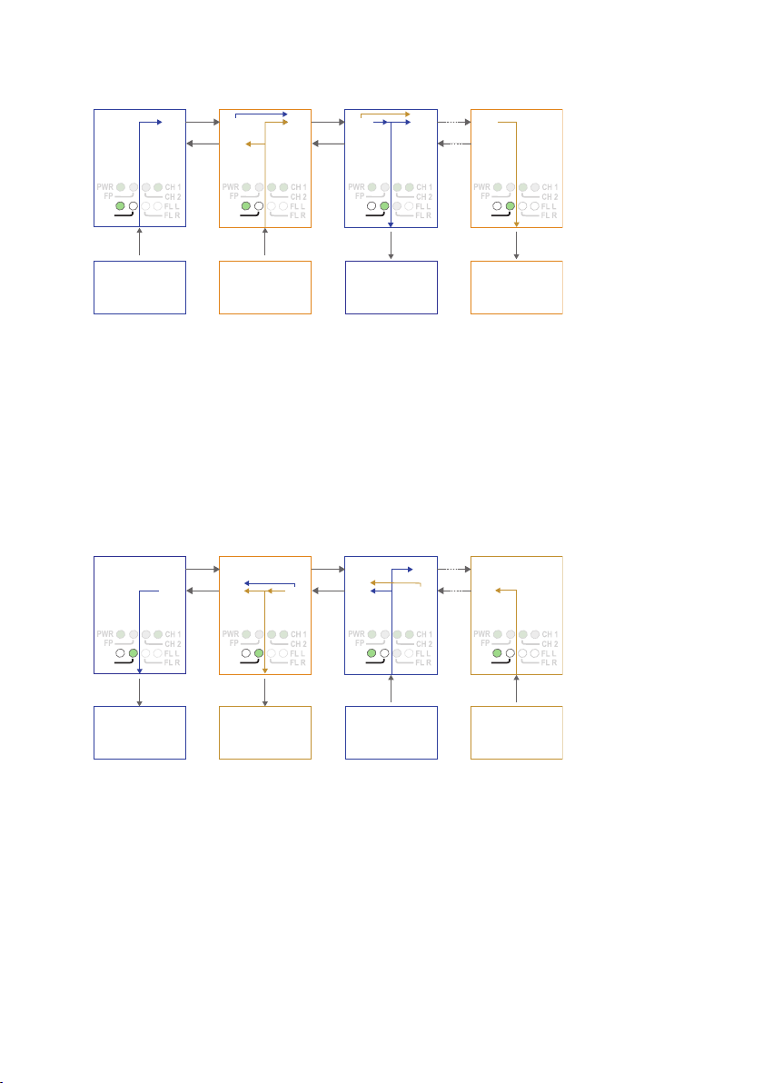
The first ODW-730 unit recieives data from communications device 1 on the RS-485
port and sends it out on optical fibre TX1 using the primary data channel.
The second ODW-730 unit receives primary channel data on optical fibre RX2. Primary
channel data is repeated out on optical fibre TX1. The second ODW-730 unit also
receives data from communications device 2 on the RS-485 port. The RS-485 data is sent
out on optical fibre TX1 using the secondary data channel.
The third ODW-730 unit receives both primary and secondary channel data on optical
fibre RX2. Both primary and secondary data are repeated out on optical fibre TX1, but
only the primary channel data is sent out on the RS-485 port.
The fourth ODW-730 unit receives both primary and secondary channel data on optical
fibre RX2. Both primary and secondary data are repeated out on optical fibre TX1, but
only the secondary channel data is sent out on the RS-485 port.
Page 24

24
6651-2255
RX2
TX2
TX1
RX1
RX2
TX2
TX1
RX1
RX2
TX2
Fibre
pair
Fibre
pair
Fibre
pair
TX1
RX1
RX2
TX2
TX1
RX1
Primary channel
Focal point
Scondary channel
Focal point
Device 1
Receiving data from
device 3 on the
primary channel
RS-485
Device 2
Receiving data from
device 4 on the
secondary channel
RS-485
Device 3
Sending data to
device 1 on the
primary channel
RS-485
Device 4
Sending data to
device 2 on the
secondary channel
RS-485
PWR
FP
TD
RD
PWR
FP
TD
RD
PWR
FP
TD
RD
PWR
FP
TD
RD
The fourth ODW-730 unit recieives data from communications device 4 on the RS-485
RX2
TX2
TX1
RX1
RX2
TX2
TX1
RX1
RX2
TX2
Fibre
pair
Faulty
segment
Fibre
pair
TX1
RX1
RX2
TX2
TX1
RX1
Primary channel
Focal point
Scondary channel
Focal point
Device 1
Sending data to
device 3 on the
primary channel
RS-485
Device 2
Sending data to
device 4 on the
secondary channel
RS-485
Device 3
Receiving data from
device 1 on the
primary channel
RS-485
Device 4
Receiving data from
device 2 on the
secondary channel
RS-485
PWR
FP
TD
RD
PWR
FP
TD
RD
PWR
FP
TD
RD
PWR
FP
TD
RD
port and sends it out on both optical fibres TX1 and TX2 using the secondary data channel.
The third ODW-730 unit receives secondary channel data on optical fibre RX1.
Secondary channel data is repeated out on optical fibre TX2. The third ODW-730 unit
also receives data from communications device 3 on the RS-485 port. The RS-485 data is
sent out on both optical fibres TX1 and TX2 using the primary data channel.
The second ODW-730 unit receives both primary and secondary channel data on optical
fibre RX1. Only the primary channel data is repeated out on optical fibre TX2, and only
the secondary channel data is sent out on the RS-485 port.
The first ODW-730 unit receives primary channel data on optical fibre RX1, and this data
is sent out on the RS-485 port.
Notice that the Ring Focal Points never repeat data coming in from optical fibre RX2.
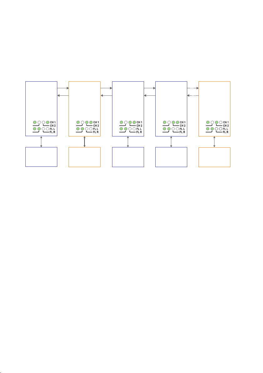
If an optical fibre segment fails, the ODW-730 Ring Focal Points will switch mode and
start sending out data on both optical fibre ports, TX1 and TX2, simultaneously.
Page 25

25
6651-2255
RX2
TX2
TX1
RX1
RX2
TX2
TX1
RX1
RX2
TX2
Fibre
pair
Fibre
pair
TX1
RX1
RX2
TX2
TX1
RX1
Primary channel
Focal point
Scondary channel
Focal point
Device 1
Receiving data from
device 3 on the
primary channel
RS-485
Device 2
Receiving data from
device 4 on the
secondary channel
RS-485
Device 3
Sending data to
device 1 on the
primary channel
RS-485
Device 4
Sending data to
device 2 on the
secondary channel
RS-485
PWR
FP
TD
RD
PWR
FP
TD
RD
PWR
FP
TD
RD
PWR
FP
TD
RD
Faulty
segment
The other ODW-730 units will continue to send data out in as many directions as possible. Consequently, all communication devices will still be able to communicate with each
other. Notice that the Ring Focal Points are now repeating incoming data from optical
fibre RX2.
Page 26

26
6651-2255
Redundant ring, dual channel, V-mode configuration
Redundant fibre pair. Not used under normal operation.
RX2
TX2
Device 1
Communicates with
device 3 on the
primary data channel
Device 2
Communicates with
device 4 on the
secondary data channel
Device 3
Communicates with
device 1 on the
primary data channel
Device 5
Communicates with
device 2 on the
secondary data channel
TX1
RX1
RX2
TX2
TX1
RX1
RX2
TX2
RS-485 RS-485 RS-485
Fibre
pair
Fibre
pair
Fibre
pair
RS-485
TX1
RX1
RX2
TX2
TX1
RX1
PWR
FP
TD
RD
PWR
FP
TD
RD
PWR
FP
TD
RD
Device 4
Communicates with
device 1 on the
primary data channel
RS-485
Fibre
pair
RX2
TX2
TX1
RX1
PWR
FP
TD
RD
PWR
FP
TD
RD
FP LED
is on to
indicate
focal point
Primary channel
Focal point
S1: 8 ON
S2: 2 ON
S2: 3 ON
S2: 4 OFF
S2: 5 ON
Secondary channel
Focal point
S1: 8 ON
S2: 2 ON
S2: 3 ON
S2: 4 ON
S2: 5 ON
Primary channel
Ring member
S1: 8 ON
S2: 2 ON
S2: 3 OFF
S2: 4 OFF
S2: 5 ON
Primary channel
Ring member
S1: 8 ON
S2: 2 ON
S2: 3 OFF
S2: 4 OFF
S2: 5 ON
Primary channel
Ring member
S1: 8 ON
S2: 2 ON
S2: 3 OFF
S2: 4 ON
S2: 5 ON
In a redundant ring an extra fibre pair is used. This extra fibre pair is used to carry data if
one of the other fibre pairs breaks.
In dual channel mode it is possible to use two separate data streams in a single ODW730 network. However, all ODW-730’s must be set to the same speed and data
format. This, of course, limits the number of possible applications for a dual channel
network.
In V-mode mode an ODW-730 network will behave as a 4-wire bus. Where the first
ODW-730 (leftmost in the picture below) will able to communicate in full duplex with
any other unit, but other units are incapable of communicating with each other.
Prepare the fibre optical network
• Configure all ODW-730 units for the correct speed and data format using DIPswitches S1:1 – S1:7. Again, notice that all ODW-730’s must be set to the same speed
and data format.
• Select RS-485 2 wire and 4-wire mode using DIP-switch S2:1 (OFF = 2-wire,
ON = 4-wire).
• Enable the RS-485 termination / fail-safe if required using DIP-switches S3:1 – S3:4
(S3:1 and S3:2 = 4-wire termination, S3:3 and S3:4 = 2-wire termination)
• Set DIP-switch S1:8 in the ON position (V-mode) on all ODW-730 units.
• Set DIP-switch S2:2 in the ON position (redundant ring) on all ODW-730 units.
• Set DIP-switch S2:5 in the ON position (dual channel system) on all ODW-730 units.
• All ODW-730 units that are to use the primary data channel (“blue” units in the
picture above) must have DIP-switch S2:4 set to the OFF position. Units that are to
use the secondary data channel (“orange” units in the picture above) must have DIPswitch S2:4 set to the ON position.
• One of the primary data channel and one of the secondary data channel ODW-730
units must be configured as a Ring Focal Point by setting DIP-switch S2:3 to the ON
position.
Page 27

27
6651-2255
• Set DIP-switch S2:6 as desired. See page 34 “Status port” for more information.
• Verify that DIP-switches S2:1 and S2:8 are set in the OFF position.
• Connect the fibre pairs between the units. Always connect CH 1 from one unit to CH
2 on the next unit as shown in the picture above.
• Connect the power supply to all units and verify that all fibre links become active.
(CH 1 and CH 2 LED’s are on, FL L and FL R LED’s are off).
• Connect the communication devices to the corresponding ODW-730 unit.
• The network is now up and running.
Note: In an ODW-730 fibre optic network there will be some additional processing
delays that do not exist in an electrical bus. It is possible that the application must be
adjusted to accommodate these delays if using many ODW-730 units in a large network.
See page 32 “Calculating system processing delay” for more information on how to
determine the overall system delay time.
Page 28

28
6651-2255
Data transport in redundant ring, dual channel, V-mode configuration
RX2
TX2
Device 1
Sending data to
device 3 and 4 on the
primary channel
Device 2
Sending data to
device 5 on the
secondary channel
Device 3
Receiving data from
device 1 on the
primary channel
Device 5
Receiving data from
device 2 on the
secondary channel
TX1
RX1
RX2
TX2
TX1
RX1
RX2
TX2
RS-485 RS-485 RS-485
Fibre
pair
Fibre
pair
Fibre
pair
RS-485
TX1
RX1
RX2
TX2
TX1
RX1
Device 4
Receiving data from
device 1 on the
primary channel
RS-485
Fibre
pair
RX2
TX2
TX1
RX1
PWR
FP
TD
RD
PWR
FP
TD
RD
PWR
FP
TD
RD
PWR
FP
TD
RD
PWR
FP
TD
RD
Primary channel
Focal point
Secondary channel
Focal point
The first ODW-730 unit recieives data from communications device 1 on the RS-485
port and sends it out on optical fibre TX1 using the primary data channel.
The second ODW-730 unit receives primary channel data on optical fibre RX2. Primary
channel data is repeated out on optical fibre TX1. The second ODW-730 unit also
receives data from communications device 2 on the RS-485 port. The RS-485 data is sent
out on optical fibre TX1 using the secondary data channel.
The third and fourth ODW-730 units receive both primary and secondary channel data
on optical fibre RX2. Both primary and secondary data are repeated out on optical fibre
TX1, but only the primary channel data is sent out on the RS-485 port.
The fifth ODW-730 unit receives both primary and secondary channel data on optical
fibre RX2, but only the secondary channel data is sent out on the RS-485 port.
Page 29

29
6651-2255
The fifth ODW-730 unit recieives data from communications device 5 on the RS-485
RX2
TX2
Device 1
Receiving data from
device 4 on the
primary channel
Device 2
Receiving data from
device 5 on the
secondary channel
Device 3
Not sending or
receiving any data
Device 5
Sending data to
device 2 on the
secondary channel
TX1
RX1
RX2
TX2
TX1
RX1
RX2
TX2
RS-485 RS-485 RS-485
Fibre
pair
Fibre
pair
Fibre
pair
RS-485
TX1
RX1
RX2
TX2
TX1
RX1
Device 4
Sending data to
device 1 on the
primary channel
RS-485
Fibre
pair
RX2
TX2
TX1
RX1
PWR
FP
TD
RD
PWR
FP
TD
RD
PWR
FP
TD
RD
PWR
FP
TD
RD
PWR
FP
TD
RD
Primary channel
Focal point
Secondary channel
Focal point
port and sends it out on optical fibre TX2 using the secondary data channel.
The fourth ODW-730 unit receives secondary channel data on optical fibre RX1.
Secondary channel data is repeated out on optical fibre TX2. The fourth ODW-730 unit
also receives data from communications device 4 on the RS-485 port. The RS-485 data is
sent out on optical fibre TX2 using the primary data channel.
The third ODW-730 unit receives both primary and secondary channel data on optical
fibre RX1. Both primary and secondary data are repeated out on optical fibre TX2. None
of the data is sent out on the RS-485 port.
The second ODW-730 unit receives both primary and secondary channel data on optical
fibre RX1. Both primary and secondary data are repeated out on optical fibre TX2, but
only the secondary channel data is sent out on the RS-485 port.
The first ODW-730 unit receives both primary and secondary channel data on optical
fibre RX1, but only the primary channel data is sent out on the RS-485 port.
Notice that the primary channel Ring Focal Point never repeats primary channel data
coming in from optical fibre RX2 and that the secondary channel Ring Focal Point never
repeats secondary channel data coming in from optical fibre RX2
Page 30

30
6651-2255
If an optical fibre segment fails, the ODW-730 Ring Focal Points will switch mode and
RX2
TX2
Device 1
Sending data to
device 3 and 4 on the
primary channel
Device 2
Sending data to
device 5 on the
secondary channel
Device 3
Receiving data from
device 1 on the
primary channel
Device 5
Receiving data from
device 2 on the
secondary channel
TX1
RX1
RX2
TX2
TX1
RX1
RX2
TX2
RS-485 RS-485 RS-485
Fibre
pair
Fibre
pair
Fibre
pair
RS-485
TX1
RX1
RX2
TX2
TX1
RX1
Device 4
Receiving data from
device 1 on the
primary channel
RS-485
RX2
TX2
TX1
RX1
PWR
FP
TD
RD
PWR
FP
TD
RD
PWR
FP
TD
RD
PWR
FP
TD
RD
PWR
FP
TD
RD
Faulty
segment
Primary channel
Focal point
Secondary channel
Focal point
RX2
TX2
Device 1
Receiving data from
device 4 on the
primary channel
Device 2
Receiving data from
device 5 on the
secondary channel
Device 3
Not sending or
receiving any data
Device 5
Sending data to
device 2 on the
secondary channel
TX1
RX1
RX2
TX2
TX1
RX1
RX2
TX2
RS-485 RS-485 RS-485
Fibre
pair
Fibre
pair
Fibre
pair
RS-485
TX1
RX1
RX2
TX2
TX1
RX1
Device 4
Sending data to
device 1 on the
primary channel
RS-485
RX2
TX2
TX1
RX1
PWR
FP
TD
RD
PWR
FP
TD
RD
PWR
FP
TD
RD
PWR
FP
TD
RD
PWR
FP
TD
RD
Faulty
segment
Primary channel
Focal point
Secondary channel
Focal point
start sending out data on both optical fibre ports, TX1 and TX2, simultaneously.
The third and fourth ODW-730 units will now switch direction so that data is sent out
on optical fibre TX1 instead of TX2. (Not shown in the picture above, is that the third
ODW will continue to send data out on TX2).
Consequently, communications device 1 is still able to communicate with device 3 and 4.
And communications device 2 is still able to communicate with device 5.
Page 31

31
6651-2255
LED indication during optical link failure
RX2
TX2
TX1
RX1
RS-485
PWR
FP
TD
RD
RX2
TX2
TX1
RX1
RS-485
PWR
FP
TD
RD
RX2
TX2
TX1
RX1
RS-485
PWR
FP
TD
RD
RX2
TX2
TX1
RX1
RS-485
PWR
FP
TD
RD
Fibre
pair
Fibre
pair
Fibre
pair
FL L
LED
is on
CH 1
LED
is off
CH 2
LED
is off
Faulty
segment
If an optical fibre segment fails, to determine wich fibre segment has failed, look at the
FL L, FL R, CH 1 and CH 2 LED’s as show in the picture above.
Page 32

32
6651-2255
Calculating system processing delay
Data exchange between commuinication devives via an ODW-730 fibre optic link,
will be delayed due to the length of the optical fibre and the signal processing within the
ODW-730. The signal processing delay is dependent on the data rate, and the fibre delay
is dependent on the total length of the optical fibre. The additional time resulting from
the optical fibre and ODW-730 is the Overall system delay.
Delay @ < 1.Mbit/s
Optical fibre length delay (typical) 5 µs/km
Signal processing, electrical to fibre (max) 1 tbit + 1 µs
Signal processing, fibre to electrical (max) 0.3 µs
Signal processing, fibre to fibre (max) 1.06 µs
Note: tbit = 1 / Baud rate (Baud rate in bit/s)
Example: Calculate the maximum processing delay in a network comprising of 10 com-
munication devices and 10 ODW-730 units, using a data rate of 115.2 kbit/s, with a total
fibre length of 40 km. A data exchange between the two communication devices located
at either end of the network.
1. Fibre: The total optical fibre length delay.
40 x 5 µs = 200 µs
2. Optical repeaters: The optical repeater delay x Number of optical repeaters
(excluding the ODW-730 units connected to the communication devices that are
exchanging data).
(10 – 2) x 1.06 µs = 8.48 µs.
3. Converter electrical to fibre: Signal processing delay inside the ODW-730 that is
sending data.
1 tbit + 1 µs = 1/115200 + 1 µs = 9.68 µs
4. Converter fibre to electrical: Signal processing delay inside the ODW-730 that is
receiving data.
0.3 µs
5. The system delay is calculated by summing the delays in item 1 to 4 above
and multiplying the result by two:
2 x (200 µs + 8.48 µs + 9.68 µs + 0.3 µs) = 437 µs
Page 33

33
6651-2255
Reconfiguration time under faulty condition
The reconfiguration time is determined by the time it takes to detect a faulty fibre segment plus the time it takes to transport an error status message through to the ODW730 Ring Focal Point unit. The time to transport an error status message to the Ring
Focal Point unit is dependent on how many units the error status message has to be
repeated through and the total fibre length delay.
The time to detect a faulty fibre segment is less or equal to 3 µs.
The time to repeat an error status message through any unit is 0.8 µs
During reconfiguration data may be corrupted or lost.
Example: Calculate the maximum reconfiguration time in a network comprising of
10 ODW-730 units and a total fibre length of 40 km.
1. Error detection: The time it takes to detect a faulty fibre segment.
Always 3 µs.
2. Fibre: The total optical fibre length delay.
40 x 5 µs = 200 µs
3. Optical repeaters: The optical repeater delay x Number of optical repeaters
(excluding the ODW-730 units connected to the communication devices that are
exchanging data).
(10 – 2) x 0.8 µs = 6.4 µs.
4. The reconfiguration time is calculated by summing the delays in item 1 to 3
above:
3 µs + 200 µs + 6.4 µs = 209.4 µs
Page 34

34
6651-2255
About the interfaces
Power terminal
The power terminal has two independent inputs, +VA and +VB, allowing redundancy
should either fail. The ODW-730 power supply is galvanically isolated from all other
internal electronics.
Optical fibre interfaces
ODW-730 uses Small From Factor Pluggable (SFP) transceivers that are in compliance
with the Multi-Sourcing Agreement (MSA). This means that a wide range of different fibre
tranceivers and connectors can be used.
RS-485 interface
A 4 position detachable screw terminal that can handle full duplex data rates up to
1.5 Mbit/s and can be set to either 2- or 4-wire RS-485 system.
When 4-wire RS-485 is selected, the terminals T/R+ and T/R– will always be set to
transmit and terminals R+ and R– will always receive data.
Manchester coded protocol can be tranferred with Synchroous mode.
Status port
The status port connects to an internal relay wich may be used to trigger an external
alarm if a fault condition occurs. During normal operation pins 1 and 2 are in contact
with each other, and pins 2 and 3 are isolated. During an optical link failure, or power
failure, pins 1 and 2 are isolated, and pins 2 and 3 are in contact with each other.
Optical link failures can be classified in to two categories, local or remote, as indicated by
the FL L and FL R LED’s. A local link failure is when an optical link is down at this
particular unit. A remote link failure is when an optical link is down at some other unit.
From the factory, the status port is set to trigger on both types of link failures.
However, by setting DIP-switch S2:6 to the ON position, the status port will only
trigger when a local link failure has occured.
Page 35

Page 36

Westermo • SE-640 40 Stora Sundby, Sweden
Tel +46 16 42 80 00 Fax +46 16 42 80 01
E-mail: info@westermo.com
www.westermo.com
Sales Units
Sweden
Westermo Data Communications
Svalgången 1, Vallbyinstitutet, 724 81 Västerås
Tel: +46 (0) 21 548 08 00 • Fax: (0) 21 35 18 50
info.sverige@westermo.se • www.westermo.se
United Kingdom
Westermo Data Communications
Talisman Business Centre
Duncan Road, Park Gate, Southampton. SO31 7GA
Tel: +44 (0) 1489 580 585 • Fax: +44 (0) 1489 580 586
sales@westermo.co.uk • www.westermo.co.uk
Germany
Westermo Data Communications
Goethe Strasse 67
DE-68753 Waghäusel
Tel: +49 (0) 7254 95400-0 • Fax: +49 (0) 7254-95400-9
info@westermo.de • www.westermo.de
Austria
Westermo Data Communications
Tel: +43 (0) 72030 3920 • Fax: +43 (0) 2235 86131
info@westermo.at • www.westermo.at
France
Westermo Data Communications
Bat. A, 9 Chemin de Chilly
FR-91160 Champlan
Tel: +33 1 69 10 21 00 • Fax: +33 1 69 10 21 01
infos@westermo.fr • www.westermo.fr
Singapore
Westermo Data Communications
2 Soon Wing Road #08-05,
Soon Wing Industrial Building
Singapore 347893
Tel: +65 6743 9801 • Fax: +65 6745 0670
sales@westermo.com.sg • www.westermo.com.sg
North America
Westermo Data Communications
939 N. Plum Grove Road, Suite F,
IL 60173 Schaumburg, USA
Tel: +1 847 619 6068 • Fax: +1 847 619 66 74
info@westermo.com • www.westermo.com
Taiwan
Westermo Data Communications
F2, No. 188, Pao-Chiao Rd. Shing-Tien City,
Taipei 23145
Tel: +886 2 8911 1710
sales.cn@westermo.com • www.cn.westermo.com
China
Westermo Data Communications
2F Building B
No.1618 Yishan Road
Shanghai 201103
Tel: +86 21 6145 0400 • Fax: +86 21 6145 0499
sales.cn@westermo.com • www.cn.westermo.com
Westermo Teleindustri AB have distributors in several countries, contact us for fur ther information.
REV.B 6651-2255 2012-11 Westermo Teleindustri AB, Sweden – A Beijer Electronics Group Company
 Loading...