

Page 1

OPERATORS
MANUAL
358
MARINE
Three,
388
DIESEL
Four,
ENGINES
428
Four
J'W
PUBLICATION
REVISION.
MARCH
NO.
3
2018
037435
'WESTERBEKE
j
WESTERBEKE
j
MYLES
WEB
SITE:
NMM4
----
~--
CORPORATION•
STANDISH
INDUSTRIAL
WWW.WESTERBEKE.COM
Member National Marine Manufacturers Association
150
JOHN
PARK•
HANCOCK
TAUNTON
MA
ROAD
02780
Page 2

A
WARNING
Exhaust
colorless
unconsciousness
exposure
•Dizziness
gasses
gas.
carbon
can
include:
•Nausea
·•Headache
•
Weakness
IF
YOU
BET
OUT
seek
medical
until it
and
DR
ANYONE
INTO
luls
been
,.t
THE
attention.
contain
carbon
Monoxide
and
death.
Sleepiness
ELSE
EXPERIENCE
FRESH
AIR
Shut
inspected
Monoxide,
is
poisonous
Symptoms
•
Throbbing
•Muscular
•Vomiting
•Inability
of
to
ANY
an
carbon
in
Twitching
OF
l•EBIATELY.
down
the
unit
and
repaired.
A
WARN/NB
WESTERBEKE
bulkhead
WESTERBEKE
CARBON
living/s/eepiilg
Tiiey
obtainable
DECAL
and
near
your
also
MONOXIDE
are
inexpensive
at
your
quarters
odorless
and
Temples
Think
niEsE
N
symptoms
and
is
should
engine
recommends
and
can
cause
Monoxide
Coherently
SYMPTOMS,
do
not
restart
provided
be
fixed
or
DETECTORS
of youi
and
easily
local
marine
persist,
by
to
a
generator.
installing
in
the
vessel.
store.
·
...
I .
CALIFORNIA
PROPOSITION
Marine
exhaust
are
known
to
cause
and
other
diesel
and
some
to
the
cancer,
reproductive
65
and
of
State
WARNING
gasoline
its
birth
engine
constituents
of
California
defects,
harm.
Page 3

SAFETY
INSTRUCTIONS
INTRODUCTION
Read
this
safety
manual
caused
by
failure
precautions.
take
the
personnel,
The
following
the
American
PREVENT
A
while
power.
II
Do
enclosures and covers in place.
II
Shut off electrical power before accessing electrical
equipment.
II
Use insulated mats whenever working on electrical
equipment.
II
Make sure your clothing and skin
(particularly shoes) when handling electrical equipment.
II
Remove wristwatch and all jewelry when working on
electrical equipment.
PREVENT
A
exhaust
Know
necessary
and
your
safety
Boat
ELECTRIC
WARNING:
engine
is
Lethal
voltage
not operate this machinery without electrical
BURNS -HOT
WARNING:
system
hat!
Ill Monitor engine antifreeze coolant level at the plastic
coolant recovery tank and periodically at the filler cap
location on the water jacketed exhaust manifold, but only
when the engine
A
WARNING:
1111
In
case of
before touching the engine or checking the coolant.
an
engine overheat, allow the engine
carefully.
to
follow
fundamental
when
dangerous
precautions
to
protect
Most
conditions
machinery.
instructions
and
Yacht
are
Council
in
(ABYC)
SHOCK
Do
not
touch
AC
electrical
running,
or
Is
present
when
connected
at
these
are
ENGINE
Oa
not
touch
hat
engine
components. A running
is
COLD.
Steam
can
cause
injury
accUlents
rules
are
and
exist
yourself,
your
compliance
standards.
connections
to
shore
connections!
dry,
not damp
parts
or
engine
gets
or
death!
to
and
with
cool
.
very
PREVENT
A
Ii
Prevent flash
sparks to occur near the carburetor, fuel line,
pump, or other potential sources
vapors. Use a suitable container to catch all
removing the fuel line, carburetor, or fuel
11\l
Do
Backfire can cause severe injury or death.
Ill
Do not smoke or permit
the fuel system. Keep the compartment and the
engine/generator clean and free
chances of
I'
Be aware - diesel fuel will burn.
PREVENT
A
injury
l!J
Follow re-fueling safety instructions.
hatches closed when fueling. Open and ventilate cabin
after fueling. Check below for fumes/vapor before
running the blower. Run the blower for four minutes
before starting your engine.
!kl
All fuel
when
ventilated area away from spark-producing equipment
and out
Ell
Do not
E?J
Shut off the
the fuel system.
spill.
sources
servicing.
the fuel system.
iJ
Do not alter or modify the
fJ Be sure all fuel supplies
11~
Be certain fuel line fittings are adequately tightened
free of leaks.
a Make sure a
properly maintained. Be familiar with its proper use.
Extinguishers rated ABC by the
for all applications encountered in this environment.
BURNS -FIRE
WARNING:
not operate with the air cleaner/silencer
fires.
fire.
Fire
can
cause
injury
Do not smoke or permit
of
flames
or sparks to occur near
of
debris to minimize the
Wipe up
all
spilled fuel and engine
or
spilled
death!
fuel
filters.
BURNS -EXPLOSION
WARNING:
or
death!
handling and storing fuels. Store fuel in a well-
fill
DO
of
Explosions
vapors
are
highly
of
the reach of children.
the fuel tank(s) while the engine
fuel
service
Take
NOT allow
fire
near
the
Ensure proper ventilation exists when servicing
fire
extinguisher is installed nearby and is
from
fuel
explosive.
valve
care in catching
any
smoking; open
fuel
system
fuel
have
Use
at
the engine
or engine
system.
a positive shutoff
NFPA
vapors
Keep
the vessel's
extreme
is
when
any
fuel
flames,
when
are appropriate
flames
fuel
removed.
can
runni.Qg.
or
filter,
fuel
or
fuel
when
oil.
cause
care
servicing
that might
or other
valve.
and
Engines
& Generators
i
Page 4

SAFETY
INSTRUCTIONS
ACCIDENTAL
A
WARNING:
or
death/
11
Turn
unit's
engine.
• Make certain all personnel are clear of the engine before
starting.
•
Make certain
re-installed before starting the engine.
BATTERY
A
WARNING:
or
death!
• Do not smoke or
being serviced. Lead acid batteries emit hydrogen, a
highly explosive
arcing or
equipment in the vicinity
during servicing.
• Never connect the negative(-) battery cable
positive (
Do not test the battery condition by shorting the terminals
together.
Ventilate
accumulation of explosive gases.
disturb
is being charged.
•
Avoid
burns or sparks
wristwatch, rings, and
battery.
the
• Always tum the battery charger off before disconnecting
the battery connections
and reconnect it last when servicing
BATTERY
A
WARNING:
severe
• When servicing the battery or checking the electrolyte
level, wear rubber gloves, a rubber
protection. Batteries contain sulfuric acid which is
destructive.
it off at once
into the eyes inadvertently when removing electrolyte
caps.
STARTING
OFF
the
battery
Accidental
DC
breaker
selector
all
covers, guards, and hatches are
starting
on the control
switch
to
OFF
can
cause
panel
before
injury
or tum
servicing
EXPLOSION
Battery
by
lit tobacco products. Shut
+) connection
Sparks could ignite battery gases or fuel
any
compartment containing batteries
the battery charger connections while the battery
contacting
explosion
allow
an open
gas,
which can be ignited
to
terminal
the
terminals with tools, etc., to prevent
that could cause
any
..
Remove the negative lead first
can
cause
flame
near the battery
by
o~
all
prevent electrical arcmg
to
of
the
starter solenoi?.
To
avoid
sparks,
!111
explosion.
other Jewelry before handling
the
battery.
injury
elec~cal
ele~lrical
the
to
Remo~e
ACID
Injury
SUifuric
or
death!
If
it comes in contact
with
water.
acid
Acid
in
batteries
with
may
can
apron,
and eye
your skin, wash
splash on the skin or
cause
the
the.
vapors.
prevent
do
not
TOXIC
El
Iii
EXHAUST
A
WARNING:
Ensure that the exhaust system is adequate
discharged from the engine. Check the exhaust system
regularly for leaks
water-injected
Be sure the unit and its surroundings are well ventilated.
Run blowers when running the
GASES
Carbon
and
elbow
is
monoxide
make
securely attached.
(CO}
is a deadly
sure the exhaust manifold/
geµerator set or engine.
to
gas!
expel
gases
a Do not run the generator set or engine unless the boat is
equipped with a functioning marine carbon monoxide
detector that complies with ABYC A-24. Consult your
boat builder or dealer for installation of approved
detectors.
Iii For additional information, refer
(educational information on Carbon Monoxide).
A
WARNING:
odorless
nausea
ID
11
l!I Although diesel engine exhaust
AVOID
A
or
lill
gas.
or
Do
not use copper tubing in diesel exhaust systems.
Diesel
fumes
systems.
copper tubing resulting in exhaust/water leakage.
Do not install exhaust outlet where exhaust can be
through portholes, vents, or air conditioners.
exhaust discharge outlet is near the waterline, water could
enter the exhaust discharge outlet
flow
of exhaust.
exhaust
gas
is present in diesel exhaust
symptoms or signs of carbon monoxide inhalation or
poisoning
Vomiting
Dizziness
Headache
Nausea Weakness and sleepiness
MOVING
WARNING:
death!
Do not service the engine while it is running.
situation
make operating adjustments, use extreme care
touching moving parts and hot exhaust system
components.
Carbon
Inhalation
monoxide
produces
death!
can rapidly destroy copper tubing in exhaust
Exhaust sulfur causes rapid deterioration of
Avoid
overloading the craft.
fumes
from gasoline engines, carbon monoxide
are:
Inability
Throbbing
Muscular twitching
PARTS
Rotating
arises
in which it is absolutely necessary
parts
to
ABYC
(CO}
Is
Ru-like
aµd
close or restrict
gases
are not
fumes.
Some of
to
think coherently
in
temples
can
cause
TH-22
an
Invisible
symptoms,
drawn
If
the engine
as
toxic
the
Injury
If
a
to
to
avoid
the
as
Engines & Generators
ii
Page 5

Ill
Do
not
wear
equipment;
rings,
.
moving
111
Make
Keep
places
111
Do
not
.
the
engine
11
Stay
when
be
caught
HAZARDOUS
A
WARNING:
avoid
necklaces
parts
sure
all attaching
protective
at
all
times.
check
is
clear
of the
the
engine
in
these
NOISE
loss!
11
Never
operate
111
Do
not
run
an
removed.
A
WARNING:
mentally
OPERATORS
·Many
in
your
notes
carefully,
procedures.
01
of
the
Operators
to
highlight
maintain
physically
MANUAL
preceding
SAFETY
loose clothing or jewelry
wearing
or
loose jackets,
bracelets
that
..
hardware
shields
and
guards
fluid
levels
or
the
operating.
drive
shaft
and
is
running;
rotating
High
noise
an
engine without its·muffler
engine
Oo
not
incapacitated by
safety
Manual
critical infonnation. Read your
your
equipment,
hair and clothing
parts.
l~vels
with
the air intake (silencer)
work
an
tips
and
along
with
when
shirts,
could
be
is
properly
in
their respective
drive
belt's
the
transmission
can
cause
machinery
fatigue!
warnings are'fepeated
other cautions
and
follow
servicing
sleeves,
caught
tightened.
tension
can
hearing
installed.
when
you
and
manual
all safety
INSTRUCTIONS
in
while
coupling
easily
are
ABYC,
.
~NSTAR.LING
Read
for safety
tions
ABYC
"Safety
Order
ABYC
613
Annapolis,
(
410)
·
www.abycinc.~rg
NFPA
"Fire Protection Standard for Motor Craft"
Order
NFPA
1 Batterymarch Park
P.O.
Quincy,
USCG (United States Coast
"CFR
Code of Federal Regulations
Order
U.S.
Washington,
NF
the
following
codes
when
(American
Standari:ls
From:
Third
Dtreet,
MD
990-4460
(National Fire Protection Association)
From:
Box
9101
MA
33
AND
From:
Government
PA
AND
USCG
PUBLICATIONS
MARINE
and
installing your UNIVERSAL
21403
02269-9101
CFR46"
D.C.
ENGINES
ABYC,
Boat
for Small Craft" ·
Suite
Printing Office
20404
NFPA
standards.
and
Yacht
10
Guard)
Follow
AND
and
USCG
their
Council)
FOR
GENERATORS
publications
recommenda-
engine
ENGINE
Preparations
ough
(ABYC)
sources
Sections
All
Regulations
AND
examination
standar.ds.
including
of
H-32
H-33
P-1
Installatiion of Exhaust Systems
and
P-4
Marine
E-11
TA
Batteries
installations
GENERATOR
to
install
an
engine should begin
of
the
American
These standards are a combination of
the
USCG
the
ABYC
standards of particular interest
Ventilation
Diesel
Auxilliary
AC & DC
(FCR).
for boats using diesel
Fuel
Systems
Engines
Inboard
must
Engines
Electrical Systems on Boats
and
Battery Chargers
comply
INSTALLATIONS
with a thor-
Boat
and
Yacht
and
the
NFPA.
fuel
for
Propulsion
and
Transmissions
with
the
Federal Code of
Council's
are:
Engines & Generators
iii
Page 6

When
installing WESTERBEKE engines
to
the
attention be paid
following
INSTALLATION
and
generators it
information:
is
important that strict
CODES
Strict federal regulations,
when
AND
REGULATIONS
installing engines
ABYC
guidelines,
and
generators in a marine environment.
and
safety codes must be complied with
SIPHON·BREAK
For installations where the exhaust manifold/water injected exhaust elbow
or
will
be below the vessel's waterline, provisions must be made
raw
break in the
minimum of
the
exhaust manifold
raw
water
If
you
have
to
the vessel's waterline under
water supply hose
20" above
damage
any
doubt about
to
injection
the
the
vessel's waterline.
engine
to
the
exhaust
Failure
port is at
and
the
position of
the
or
below
possible
vessel's various operating conditions, install a
flooding
the
water-injected exhaust elbow relative
siphon-break.
NOTE:
A siphon-break
operation.
engine
EXHAUST
The
Exhaust Hose
and
and
system
under
Failure
damage.
SYSTEM
exhaust system's hose
is
turns without the need of additional
turns.
In this regard, a single length of corrugated exhaust hose can be
MUST
any
sea conditions
requires
to
properly maintain a siphon-break
Consult
recommended. The use of
be
designed
periodic inspection and cleaning
the
siphon-break manufacturer for proper
MUST
be certified
fitting
to
and
prevent
at
the
any
angle of vessels
for
this
and
entry
type
of water into
elbow.
This hose must be looped a
to
the
load
of
can
marine
of hose allows for extreme bends
clamps
heel.
to
install a siphon-
use
a siphon-break
waterline
the
boat.
result
use.
Corrugated Marine
to
accomplish these bends
the
will
to
ensure
in
catastrophic
maintenance.
exhaust system
is
close
when
result
proper
used.
to
in
AVAILABLE
YOUR
DEALER
SIPHON~BR'EAK
wop·
The
FROM
WESTERBEKE
WITH
STAINLESS
A
detailed
engines
to
and
download
Marine
Installation
generators,
from
our
Manual
is
supplied
website
at
Engines & Generators
covering
with
www.westerbeke.com.
iv
each
gasoline
unit. A pdf
and
diesel,
is
available
Page 7

TABLE
OF
CONTENTS
Introduction
Warranty Procedures ...................................... 2
Serial Number Locations ............................... 3
Ordering Parts ................................................ 3
Parts
Identification
Transmission
Propeller Recommendations .........................
Fuel,
Engine
Oil Pressure ................................................... 6
· Coolant Recovery Tank ................................. 6
Preparations
Admiral
Captain
Starting/Stopping
Engine
The
Daily
Warning
Maintenance
Cooling
Changing Coolant ................. ~ ...................... 16 Torquing Cylinder Head Bolts
Thermostat ...................................................
Raw Water Intake Strainer ..........................
Raw Water Cooling Circuit .........................
Heat Exchanger ...........................................
Raw Water
Zinc Anode ..................................................
Air Intake/Silencer .......................................
Fuel
System
Fuel/Water
Fuel Filters ................................................... 20
Fuel Lift Pumps ...........................................
Fuel Injectors ...............................................
Fuel Injection Pump ....................................
Glow
.........................................................
............................................
Data
...............................................
Oil
and
for
Control
Control
Break-In
Operation
Lights,
Schedule
System
........................... : .......... ~ ...........
Pump .........................................
Coolant
Initial
Panel
.........................................
Panel
.........................................
Procedure
Procedure
...........................................
Alarms
..............................
Start-Up
.........................
.............................
...............................
and
Circuit
(Chart)
Breaker
.........................
.......................................................
Separator ................................... 20
Plugs ..................................................
2
.4
5
.5
6
7
8
9 Battery Care........................ . ...................... 30
1 o
11
12
....
13
14 Adjusting Idle Speed .............. ; ...................
16
17
18
18
18
18
19
19
20
20
21
21
21
Engine
Oil
Remote
Torque
Tachometer
Water
Starter
DC
Wiring
Wiring
Engine
HBW·ZF
HBW·ZF
JS
Borg
Metric
Specifications
Lay-Up
Suggested
Lubricating
Changing the
Changing the
Pressure
Testing Oil Pressure .....................................
........................................................
Oil
Filter
Specifications
............................................
Oil Filter ................................ 22
Oil ......................................... 22
(Optional)
.......................................
........................................................
Heater
Motor
Electrical
Alternator Troubleshooting ......................... 29
Schematic
Diagram
Troubleshooting
Coolant Temperature/Oil Pressure Gauges .34
Belt Tension and Maintenance .................... 35
Valve Clearance
Torquing Cylinder Head Bolts
Valve Clearance
and
BW
Warner
Coolers ................................................... 46
Oil
.....................................................
.....................................................
System
.........................................
..............................................
..................................................
....................................
(358)
(388/428)
Transmissions
Transmission
......................................
(Chart)
Transmissions
Transmission
Conversion/Hardware
....................................................
W35B Three ................................................ 48
W38B Four .................................................. 50
W 42B
Four
.................................................. 52
and
Recommissioning
Spare
Parts
.....................................
22
23
23
..............................
24
24
25
26
27
29
31
31
.32
.35
(358)
... : .....
.36
.........................
(388/428)
..........................
......
~
....................
..................................
................................
(Chart)
...........................
J ...... 36
..
...............
.37
37
38
.41
42
44
.47
48
54
.56
·
Engines & Generators
1
Page 8

This
WESTERBEKE
WESTERBEKE's
technology.
dependable
Thank
In
order
important
manual
ual
carefully
out.
nearest
This
provided
WESTERBEKE
equipment,
WESTERBEKE' S installation
We
performance
you
for
to
get
that
is
designed
and
Should
your
WESTERBEKE
is
your
operators
and a technical
contact
WARRANTY
Your
WESTERBEKE
folder.
If,
after
form
you
have
registering
writing
serial
Customer
your
with
model
number
Identification
Diesel
long
ye~
take
great
pride
of our engines
selecting
the
you
WESTERBEKE.
full
use
and
operate
observe
engine
dealer.
and
to
help
you
,illl
require
dealer
manual.
manual
If
you
your
WESTERBEKE dealer
PROCEDURES
Warranty
60
days
of submitting
not
received
warranty,
and
please
information,
commission
INTRODUCTION
Engine is a product of
of experience
in
the superior durability
benefit from your engine, it
main~n
do
this.
the
safety precautions
servicing, contact
for
assistance.
A parts catalog
is
available
are
planning
manual.
is
iftcluded in a separate
a customer identification
contact
including
date.
Card
and
it
Please
the
Warranty
the
and
advanced
generators.
correctly.
read
is
also
from
to
install
for
factory
the
engine's
this
through-
your
your
Registry
i::rus
this
·
card
in
and
is
man-
PRODUCT
Product software, (technical
brochures
WESTERBEKE
WESTERBEKE
CONTENT OF SUCH
RANTIES
THERETO,
COMPLETENESS THEREOF AND
BE
UABLE
INCURRED
OF
THE
WESTERBEKE
span
and
product software. The proguct software provided
WESTERBEKE
other suppliers, must
sively
not
only
representatives of WESTERBEKE or the supplier
be
consulted
product software being consulted
NOTES,
As
this
maintenance schedules,
engine,
CAUTIONS,
SOFTWARE
data,
and
catalogs), provided
are not within WESTERBEKE's
CANNOT BE RESPONSIBI.E
SOFTWARE,
OR
REPRESENTATIONS WITH RESPECT
INCLUDING
FOR
ANY
IN CONNECTION
FURNISHING
customers should
between
the
printings of WESTERBEKE product
unavoidable existence of earlier
products, whether
as
the
definitive authority
makes
good sense but
to
determine
CAUTIONS
manual takes
critical information
and
WARNINGS.
ACCURACY,
TYPE
OF
OR
USE
not
and
cannot
the
accuracy and
AND
WARNINGS
you
through
and
troubleshooting of your
will
parts lists,
from
sources other
MAKES
TIMEUNESS
WIU
IN
DAMAGE
WITH
OR
ARISING OUT
OF SUCH
keep
in
mind
WESTERBEKE
from
WESTERBEKE
be
relied
on
the
respective
is
imperative
by
the
customer.
the
operating
be highlighted
An
explanation
manuals,
FOR
NO
NO
OR
SOFTWARE.
upon
that
currentness
by
than
control.
THE
WAR-
OR
EVENT
INJURY
the
time
software
with
exclu-
product.
appropriate
in
question
of
procedures,
marine
NOTES,
follows:
or
It
the
Customer
MR.
MAIN
HOMETOWN,
Model
Expires
The
meric
ufacture
date
consists
acter
D=
and
manufacture.
Identification
ENGINE
STREET
358
Three.
10/15/02
WESTERBEKE
number
of
your
code
is
placed
of a character
indicates
1990s
),
the
the
second
OWNER
USA
Serial
engine serial number
that
can
assist in determining
WESTERBEKE
at
the
end of the engine serial number
followed
the
decade
(A=1960s, B=l970s,
first
number
and
third
numbers
#
_____
engine. The manufacturer's
by
three
represents
represent
is
numbers.
the
year
0402
an
the
C=1980s,
in.
the
alphanu-
date of
The
the
decade,
month
man-
char-
of
and
NOTE:
An
operating procedure essential
A
CAUTION:
obsllmnl,
your
engine.
A
WARNING:
lowed,
can
Procedures
can
result
result
which,
in
the
damage
ProcedufllS
in
personal
which,
injury
to
note.
if
not1strictly
or
destruction
if
not
properly
or
loss
of
of
fol·
life.
Engines & Generators
2
Page 9

INTRODUCTION
SERIAL
The
located
water
can
just
this
below,
technical
~VE1llt*t=Tl:I)
•
UNDER&TMBING
The
since
are
same
has
rods
Therefore,
preventive
important
nance
lubricating
ods
sediment,
important factor
high
diesel
The
however,
carburetor
component -the
function
NUMBER
engine's
on
a nameplate that
jacketed exhaust
also
be found stamped into
above
the
information
as
this
information and/or ordering parts.
MODEL
diesel
engine closely resembles
the.mechanism is essentially
arranged
general type
the
same type of
and
lubricating
to
maintenance
factors
of
the
filter
specified,
etc.)
detergent
engines.
diesel
engine
in
and
of
both.
LOCATION
model
designation and serial number are
is
mounted
manifold.
manual
will
above a closed crankcase. The crankshaft
a great extent, a diesel engine requires
fuel,
its
shut-off
on
the
provide a quick reference
SPEC
THE
as
a gasoline engine,
valves,
system.
are
proper ventilation
lubricating
elements
and
frequent
in
the
fuel
is
the consistent use of the same brand of
diesel
lubrication oil designed
does
metl1od
ignition systems are replaced
fuel
injection pump - which performs
lever.
illustration of the
W04
DIESEL
camshaft, pistons, connecting
as
a gasoline engine. The most
and
must be replaced at the time peri-
checking for contaminants
system is also essential. Another
differ from
of handling and firing
on
the side of
The engine's serial number
the
fiat
block surface located
Take
the
time
name
when
MA"'"
ENGINE
the
the
cooling systems. Fuel
the
,
gasoline engine,
same. The
and
the
·
and
proper mainte-
specifiCally
gasoline engine,
by
the
to
enter
plate
shown
seeking
SER.NO.
~ylinders
is
diesel engine
the
(water,
of
fuel.
The
a single
0
the
same
and
for
the
ORDERING
Whenever replacement parts
engine
the silver and black nameplate located
must
identify
descriptiqn
separately
packaged parts because will fit or
not
made
SPARES
Certain
WESTERBEKE
will
'J
assist
the
SPARE
sories;
PARTS
model
number and serial number
provide
us
with
this
your engine.
and
furriished
to
the
AND
spares
you
PARTS
see WESTERBEKE's
In
part number for each part
Parts
same specifications
ACCESSORIES
will
be needed
engine.
in
preparing
page
are
needed,
information
addition, include a
List).
Insist
to
support
Your
local
an
inventory of
in
this
manual.
ACCESSORIES
always
as
on
so
we
upon
generic
as
original
and
WESTERBEKE
For
provide
they
appear
the
manifold.
may
properly
complete
needed
WESTERBEKE
parts
spare
engine
part
(see
are
frequently
equipment.
maintain
parts.
acces-
brochure.
the
your
dealer
the
on
You
See
1-W-IWESTERBEKE
I Engines &
Generators
3
Page 10

PARTS
IDENTIFICATION
Connections
Secondary
Fuel Filter
W
Lube
428
Air Intake Silencer
Oil
Dipstick
FOUR
Top Engine Oil Fill
Lube Oil Filter
MARINE
DIESEL
DC Charging
Alternator
ENGINE
Shut-of!
Lever
Lube Oil
Drain Hose-
,Throttle lever
RIGHT
Top
Engine Oil Fill
SIDE
Fresh Water Fill
LEFT
SIDE.
Fuel Lift
pump
W
388
Air Intake Silencer
Lube Oil Filter
FOUR
Top
Oil Fill
Sender
MARINE
DIESEL
DC Charging
Alternator
Shut-off
Lever
Lube Oil
Drain Hose
Fresh Water
Circulating
Pump·
ENGINE
RIGHT
Top
Engine
Starter with Solenoid
SIDE
Oil Fill
Fresh Water Fill
LEFT
SIDE
90" Exhaust Elbow
Engines & Generators
4
Starter
with Solenoid
Page 11

Fresh Water
Bleed
Air
Fresh Water
Circulating
Pump
PARTS
Unit Data Plate
IDENTIFICATION
20AmpDC
Circuit Breaker
90'
Exhaust Elbow .
Heat Exchanger
LEFT
SIDE
Starter with Solenoid
W35BTHREE
MARINE
TRANSMISSION
(standard
JS
ALL
MODELS.
Transmission
DIESEL
DATA
ENGINE
General:
)
Standard
Propeller
Gear
Shaft
Fuel
Instrument
Connections
Zinc Anode
Transmission
Dipstick
JS Transmission
Ratio:
Rotation:
20 Amp DC Circuit Breaker
Lift Pump
Lube Oil Dipstick Oil Pressure
Case-hardened
gear.
Reversing
2.
47:
1.
Right
Hand.
helical
is
carried
gears
out
Sender
with
an
intermediate
by a servo
RIGHT
double
SIDE
reverse
disc
system.
DC
Charging
Alternator
Side
Oil
Fill
Shut-off
Lever
Lube
TransmiSsion
and
· .
Transmission
Propeller
Oil.
Grade.
Sump
Capacity:
Recommendations:
{;nginps
' 5
API
Spec.
CG-4,
CH4,
SAE
20W
or
SAE
Do
not
rnlx:9f8des
of
1 Quart ( 1 LitPr ).
428
FOUR
...
180.x
388THREE
358THREE
Propeller
at
full
&.
...
1611.x
...
16:0x10P.
should
allow
open
throttle
Generators
while
Cl-4,
30
exclusively.
oil
and
do
12P,
two
12P;
two
two
the
engine
underway.
SJ,
not
use
blade
blade
blade
to
reach
SL,
SM,
dr
multigrades
or
180
x10Pthree
or
t60ll1PPthree
or
160 x 8P,
its
full
better.
oils
three
rated
blade
blade.
blade.
RPM ( 3600
+I -100)
Page 12

DIESEL
FUEL,
ENGINE
OIL
AND
ENGINE
COOLANT
DIESEL
USE A DIESEL
(No.
Care
Use only clean diesel
in your
particles which might pass through the filter can damage
these
and keep it clean. The best fuel can be rendered
unsatisfactory by careless handling or improper storage
facilities.
engine's daily use
advisable:
Purchase a well-known brand of diesel fuel. The use of
additives
is
Kleen
diesel fuel when an Ultra Low Sulfur diesel is being used.
DO
Install and regularly service a good, visual-type fuel
filter/water separator between the fuel tank and the engine.
The
such filters.A
ENGINE
Use
SAE
for the engine model you have. The engine oil and filter must
be changed after the initial
Then follow the oil and filter change intervals
the
Westerbeke Corporation does not approve or disapprove of
the
break-in must.be performed using conventional oil. Oil
change intervals must be
SCHEDULE,
OIL
The engine's oil pressure, during operation, is indicated
by
normal operation, the oil pressure may range from
25
at
FUEL
FUEL
WITH
2-D
(SAE
J313)
Of
The
Fuel
fuel
injection pump is very critical; invisible dirt
finely
finished parts.
To
assure that the fuel going into the tank for your
is
to
combat BACTERIAL growth in the fuel tank
recommended such
+ cetane Boost
NOT
use
any additives containing ALCOHOL.
Raycor 500
10
MA
micron
CETANE
diesel
fuel
Supply
fuel!
clean and pure, the following practice
as
Bio-Bor and e such
to
help restore lubricity back into the
or 230 RMAM are good examples of
filter
RATING
according
The clearance of the components
It
is important
element
OF
#45
OR
to
ASTM
D975).
to
buy clean
as
Diesel
is
recommended.
OIL
a heavy duiy engine oil with an API classification and
as
specified
MAINTENANCE
use of synthetic oils.
in
the Specifications section of this manual
50 hours
SCHEDULE
If
synthetic oils are used, engine
as
in the MAINTENANCE
not extended because synthetic oils are
of
break-in operation.
as
specified in
in this manual.
PRESSURE
the
oil
pressure gauge on the instrument panel. During
psi (l.75 kg/cm
rated
rpm.
2
at idle upwards of 80 psi (5.6 kg/cm
)
HIGHER.
fuel,
is
used.
2
)
ENGINE
WESTERBEKE recommends a mixture of
and 50% distilled
chemicals that can corrode internal engine
The antifreeze performs double
run at proper temperatures
the engine
cooling circuit from rust
quality antifreeze that contains Supplemental
Additives (SCAs) that keep the antifreeze chemically
balanced, crucial
The distilled water and antifreeze should be premixed
being poured into the cooling circuit.
PURCHASING
Select a brand of antifreeze specified for diesel
Antifreeze specified for diesel engines contain a special
additive
cylinder walls. Prestone and Zerex
brands that offer antifreeze specifically for
engines. Select the pre-mix variety
will always be added
Change the antifreeze mixture according
MAJNTENANCE SCHEDULE in
COOLANT
water.
Distilled water
duty.
by
transferring heat
to
the coolant, and lubricates
and
corrosion. Look
to
long term protection.
is
It
allows
ANTIFREEZE
to
protect against cavitation erosion of
are
two
so
that
to
the cooling system
this
manual.
50%
free
surfaces.
and
protects
Cooling
nationally
the
the
when
to
the
antifreeze
from
the
the
engine
away
from
the
for a good
engines.
the
engine's
use
in
correct
needed.
MAINTENANCE
Change the engine coolant every
number of operating hours
protect and lubricate the engine have a limited
COOLANT
A coolant recovery tank kit
engine. or generator. The purpose of
allow for engine coolant expansion
engine operation, without the loss of coolant
introducing air into the cooling system. This kit
and must be installed before operating
NOTE:
located at or above
can
particular installation makes this
RECOVERY
This
tank,
be
located below
with
the
its
the
short
level
as
the
TANK
is
supplied
run
of
the
level
of
five
years
regardless
chemical additives
life.
with
each
this
recovery
and
contraction
and
is
the
engine.
of
plastic
hose,
engine's
the
necessary.
engine's
manifold,
manifold
tank
during
without
provided
is
to
before
known
diesel
mixture
of
the
that
is
to
best
but
it
if
the
NOTE:
A newly started, cold engine can have
reading
an
readings
engine and the load placed
TRANSMISSION
Refer
type of
up
to
60 psi
(4.2
oil pressure reading as
fvill vary dependinJ upon the temperature
FLUID
to
the TRANSMISSJON SECTJON
fluid
and quantity for each transmission
2
kglcm
low
as 25 psi ( 1.8
on
the engine.
).
A warmed engine can have
an
oil pressure
2
kg!cm
).
These
of
the
of
this manual for
model.
lwlWESTERBEKB
f
Eng/"9S
&
6,
Generators
Page 13

PREPARATIONS
FOR
INITIAL
START-UP
PRESTART
Before
longed
0
Check
at
0
Tum
examine
nants.
0
Check
NOTE:
transmission
O
Check
and
( +)
the
stud
0
Check
and
NOTE:
refer
0
Visually
parts,
the
0
Make
engine.
performance.
0
Make
0
Ensure
transmission.
0
Open
strainer.
INSPECTION
starting
layoff,
the
battery
your
check
the
engine
high
mark
on
the
fuel
the
the
transmission
Refer
to
the
DC
battery
cable connections. Make certain
cable
negative(-)
(this
location
the
coolant
at
the
manifold.
If
the
engine
to
the
COO
examine
disconnected
threaded
certain there
An
ample
sure
the
the
propeller shaft
the
through-hull
Inspect
engine
for
the first
the
following items:
oil
level.
Add
oil
on
the
dipstick.
supply,
then
check
fuel
filter/water
the
previous
fluid.
electrical system. Inspect
is
connected
cable
is.ll:agged).
level
has
UNG SYSTEM section
the
wires,
connections
is
supply
mounting
the
raw
separator bowl
fluid
level.
page for
to
the starter solenoid
is
connected
in
both
the
not yet been filled
engine. Look
and
unattached hoses. Check
and
engine attachments.
proper ventilation
is
necessary
installation
is
securely attached
and
prime the
water
supply.
time
or after a
to
maintain
the
fuel supply
fuel,
to
the
plastic recovery
for
loose or missing
for
is
secure.
raw
the
for
contami-
oil and
wire
connections ·
the
positive
engine ground
with
coolant,
of
this
manual.
around
the
proper engine
to
water intake
the
pro-
level
and
and
tank
PLASTIC
~--~
~...,.
GLOW
CONNECTION
RECOVERY
PLUG
TANK
Oil.FILL
CAP
DIPSTICK~
Engines &
~nerstors
7
Page 14

ADMIRAL
CONTROL
PANEL
DESCRIPTION
This
manually-operated control panel
KEY
switch
and
RPM gauge with
which
meter
in
1/10
ATURE
Fahrenheit, an
engine's
measures the engine's running time
hours.
The
panel
also includes a
gauge
which
indicates water temperature
OIL
PRESSURE gauge which measures the
oil
pressure
in
pounds per square inch, and a
control circuit VOLTAGE gauge which measures the
tem's
voltage.
switch
is
in
operation.
pushbuttons,
RPM
GAUGE:
TERS
REVOLUTIONS
PER
MINUTE
ENGINE
AND
RECALIBRATED
ACCURACY
REAR
OFTHE
is
turned
REGIS-
OF
CAN
FOR
FROM
PANEL.
one
THE
BE
THE
All
The
gauges
on
for
and
panel
are illuminated when the
remain illuminated while
also contains
PREHEAT
WATER
GRADUATED
ILLUMINATED
TURNED
TEMPERATURE
is
equipped with a
an
ELAPSED TIME
WATER
two
rubber-booted
and
one
for
START.
TEMPERATURE
ON.
IN
DEGREES
WHILE
THE
ENGINE'S
IS
170°
GAUGE:
THE
-190°
FAHRENHEIT
KEY
NORMAL
in
hours and
TEMPER-
in
degrees
DC
sys-
key
the
engine
THIS
GAUGE
AND
SWITCH
IS
OPERATING
F
(77° -88°C).
IS
IS
When
the
engine
is
the
water
temperature
temperature reading
power
was
turned off. The
when
the
key
switch
will
once
again
register
electrical
A
Admiral
necting
electrical
the
be
running.
on
engine's
separate
the
buzz.er
audible
and
should
po"'.er
is
alarm
buzzer
Panel.
The
buzzer
harness.
in a location
to
the
operator
The
buzzer
silence
oil
pressure
The
shut
down
with
gauge
will
continue
indicated
is
restored
installer
to
the
will
when
rises
Oil
ATED
ILLUMINATEDWl-ULE
ON.
PRESSURE
(2.1-4.2
by
the gauge
oil
pressure gauge
turned
off. The temperature
the
engine's true
to
the gauge.
with
harness
is
responsible
four-pin
installer
where
sound
PRESSllRE
THE
it
should
the
above
If\!
POUNgS
ENGINE'S
kg/cm').
is
will
it sound
when
engine has
15
RANGES
connection
also responsible
MUGE:
the key
temperature
is
supplied
be
dry
while
the
ignition
psi (1.1
THIS
PER
SQUARE
THE
NQl)fl.:'IAL
BElWEEN
switch
to
register
before
will
fall
with
for
electrically
on
the
for
and
where
the
engine
key
started
and
2
kg/cm
).
GAUGE
IS
INCH
KEY
(PSI)
SWITCH
OPERATING
30 -60
turned
off,
the
last
electrical
to
z.ero
gauge
when
every
con-
engine's
installing
it
will
is
is
turned
the
GRAOU·
AND
IS
TURNED
OIL
psi
IS
HOURMETER:
REGISTERS
TIME,
USED
THE
SCHEDULE.
PREHEAT
THE
POWER
THE
THIS
DC
BUTION.
START
STARTER'S
THIS
UNLESS
AT
~
ELAPSED
AND
SHOULD
AS A GUIDE
MAINTENANCE
BUTION:
CONTACTS
TO
THE
PREHEAT
IS
TRANSMITTED
POWER
IS
BUTION:
SOLENOID
BUTION
THE
PREHEAT
THE
SAME
BE
FOR
WHEN
IN
THE
PREHEAT
GLOW
PLUGS.
SOLENOID
ALSO
WILL
TIME.
TO
TRANSMITIEO
WHEN
PRESSED,
WHICH
NOT
BUTION
DEPRESSED,
SOLENOID
THE
"I"
ALSO
THE
OPERATE
TERMINAL
RECEIVES
ELECTRIC
TO
THE
ENERGIZES
CRANKS
ELECTRICALLY
IS
PRESSED
IT
CLOSES
SENDING
POWER
FUEL
START
THE
ENGINE.
AND
·
ON
AND
PUMP.
THE
HELD
'
'.---,,,r
,
AUTOMATIC
COOLANT
SUPPLIED
REACHES
ALARM
OIL
LOCATED
THE
FALL
ING
SIGNAL.
ALARM
TEMPERATURE
WITH
210°
WHICH
PRESSURE
OFF
ENGINE'S
TO
10
- 5
THE
ALARM.
~
SYSTEM
THE
INSTRUMENT
F
(99"C),
WILL
EMIT
ALARM:
THE
ENGINE'S
OIL
PRESSURE.
psi
(0.7 -0.4
IN
THIS
ALARM:
AN
THIS
AN
PANEL
SWITCH
A
CONTINUOUS
OIL
PRESSURE
OIL
GALLERY.
SHOULD
kg/cm'),
EVENT.
THE
ALARM
IFTHE
WILL
SIGNAL.
ALARM
THIS
THE
THE
SWITCH
ALARM
KEY
SWITCH:
SWITCH
ON
SUPPLIES
TO
THE
PANEL
SWITCH,
TERMINAL
CHARGING
AND
TO
BUZZER
A
PULSING
DC
VOLTMETER:
INDICATES
.BATIERY
SHOULb
BUZZER
HAS
ENGINE'S
CLOSE
SOUNDING
SWITCH
SWITCH
ENGINE'S
OIL
WILL
WILL
EMIT A PULSATING
THE
KEY
WHEN
TURNED
DC
POWER
INSTRUMENT
CLUSTER,
MONITORS
CLOSE
PREHEAT
EXCITATION
OF
THE
DC
ALTERNATOR
THE
ALARM
ENERGIZING
MODE.
THE
AMOUNT
IS
BEING
CHARGED.
SHOW
13V
TO
BEEN
COOLANT
THE
IS
PRESSURE
SOUND·
IT
IN
THE
14V.
Engines & Generators
8
Page 15

CAPTAIN
CONTROL
PANEL
DESCRIPTION
This manually-operated control panel
KEY switch, an RPM gauge, PREHEAT and START but-
tons,
an
lamps,
INSTRUMENT
one
for
ALTERNATOR
'JEST button and three indicator
OIL PRESSURE, and one for high ENGINE COOLANT
TEMPERATURE.
RPM
GAUGE:
MINUTE
REAR
OF
REGISTERS
OF
THE
PER
RECALIBRATED
THE
REVOLUTIONS
THE'ENGINE
FOR
ACCURACY
PANEL.
AND
FROM
CAN
BE
is
equipped with a
DISCHARGE, one for low
OIL
PRESSURE
ALARM
LIGHT
ALTERNATOR
ALARM
LIGHT
The panel also includes an alarm buzzer for low OIL
PRESSURE
or high COOLANT 'IEMPERATURE.
RPM gauge is illuminated when the KEY switch
The
is
turned on
and remains illuminated while the engine is in operation.
ALARM:
THE
BELOW
PULSATING
TEMPERATURE
210°F:(99°G}:
NOTE:
SOUNDING
PRESSURE
ALARM'WILLSdUND'IF
10.:.
5·psl'(0.7.:.
SIGNAL:
IN
IN
THE,
THIS:
ALARM
IS
NORMAL.
REACHES
0.4
THE
ALARM
THE
FRESHWATER
EVENT,
WILL·SOUND
ONCE
15
psi
kg/cni').
WILL
THE
WHEN
THE
(1.1
kg/cm'),
THE
INTHIS_
ALSO
COOLING
ALARM
THE
ENGINE
ENGINE'S'OIL
EVENfTHE
SOUND
IF
CIRCUIT
WILL
EMITA
KEY
SWITCH
STARTS
THE
AND
ALARM
WILL
TEST
PRESSED,
ALTERNATOR,
PRESSURE,
COOLANT
TU.RE
CutTS.
THE
OIL
THE
TURE
LIGHTS
ADDITION
ING
BUZZER.
PRESSURE
ALARM
THE
RISES
CONTINUOUS
THE
PRESSURE,
THE
FALLS
WILL
COOLANT
TO
IS
TURNED
ENGINE'S
SILENCE.
BUTTON:
WHEN
TESTS
THE
AND
TEMPERA·
CONTROL
WHEN
PRESSED,
ALTERNATOR,
WATER
AND
TEMPERA-
INDICATOR
ILLUMINATE
TO
SOUND-
ALARM
EMIT
A
SIGNAL.
ON.
THIS
OIL
THE
OIL
THE
CIR·
THE
IN
START
BUTION:
STARTER'S
BUTTON
PREHEAT
TIME.
SOLENOID
WILL
BUTTON
WATER
ALARM
WHEN
NOT
OPERATE
IS
WHICH
PRESSED
TEMPERATURE
LIGHT
PRESSED,
ENERGIZES
CRANKS
AND
HELD
THEENGINE.
ELECTRICALLY
THE
UNLESS
ATTHE
Engine_s &
THIS
THE
SAME
Generators
PREHEAT
THE
TRANSMITTED
BUTTON:
CONTACTS
POWER
TO
PREHEAT
SOLENOID
IS
ALSO
TRANSMITTED
THE
TO
----KEY
WHEN
IN
THE
PREHEAT
GLOW
PLUGS.
ALSO
THE
ELECTRIC
SWITCH:
SWITCH
SUPPLIES
INSTRUMENT
CLUSTER,
EXCITATION
.
DC
CHARGING
AND
TO
ENERGIZING
.MODE.
DEPRESSED,
SOLENOID
THE
"I"
RECEIVES
FUEL
TO
THE
START
THE
WHEN
TURNED
DC
POWER
PANEL
PREHEAT
TERMINAL
ALTERNATOR
THE
ALARM
IT
tN A PULSING
IT
CLOSES
SENDING
TERMINAL
POWER
AND
PUMP.
DC
BUTTON.
KEY
ON
TO
THE
SWITCH,
OF
BUZZER
ON
THE
THIS
IS
POWER
THE
9
Page 16

STARTING/STOPPING
PROCEDURE
THE
STARTING
The models in this manual have a 12V
assisted by a
weather starting. The air heater heats the engine
providing a rapid start with less wear on the starter.
The start
must be depressed for the time specified
Then, while keeping the
START button is depressed to crank the engine.
circuitiy is designed so that
Starting
1.
Place the transmission in neutral and advance the throttle
control to slightly open.
CAUTION:
in
neutral.
damage
vessels
2. Tum the KEY
3. Depress the
instrument panel will energize.
pulse and the electric fuel
Preheat button should be depressed in accordance with
the following chart:
SYSTEM
DC
electric starter
DC
air intake heater for both normal and cold
the
PREHEAT button
in
the preheat chart.
PREHEAT button engaged, the
Procedure
Make
certain
$,tarting
to
your
transmission,
nearby.
SWITCH
PREHEAT button and hold it.
in
the
gear
to the
pump
transmission
could
result
your
boat,
ON
position (2 o'clock).
The
alarm buzzer will
will energize.
intake air,
is
in
serious
and
The
The
.
Temperature/Preheat
Atmospheric
____
41°F(5°C)
41°F(5°C)
23°F(-5°C)
limit
NOTE:
The START button will not energize unless the
PREHEAT button
button activates the glow plugs
the
PREHEAT intennittently
plugs.
4. While still depressing the PREHEAT button, depress the
START button. This will engage the starter solenoid.
When the engine starts, release
preheat button.
oil pressure reaches
NOTE:
When starting:
A voltage drop will occur
when the preheat button
is
depressed.
Temperature
or
to
23°F
or
of
continuous
Preheating
higher
lower
is
The
.
---+---
(-5°C)
__
use
depressed. Depressing the PREHEAT
to
pulsing alarm will silence once the
5-10 psi.
Approx.
1--
Approx.
Approx.
30
seconds
in
the cylinder head so use
avoid overheating the glow
the
start switch and
10
seconds
15
seconds
20
seconds
before
Time
cranking
S. Should
CAUTION:
engine
filling
pump
cooling
enter
manifold
happening
shutoff,
cause
resulting
issue;
6. Once
oil pressure and battery charging voltage.
NOTE:
--
Starting
Make sure the lubricating oil is appropriate for the prevailing
temperature.
the Specifications section
The battery should
Use
Temperature/Preheat chart elsewhere in this section.
Stopping
To stop
place the transmission
a few moments to stabilize temperatures.
OFF
panel and engine, de-energizing the fuel
injection pump, stopping fuel flow from
engine.
Make certain the key switch
( 12 o'clock).
discharge.
operator
of
preventing the battery from discharging
key from the key switch after stopping the engine.
the
engine not start when the START button is
10
to
20
depressed for
30
wait
longer.
seconds; repeat the procedure above and preheat
Never
run
Prolonged
starting
with
is
pumping
system
the
draining
of
the
the
engine is running.
NOTE:
engine. Depressing the
second intervals will help stabilize the engine rpm until
the engine operating temperature reaches 170
(77
- 88°C)
When the engine is running
depressed, a charging load on the DC alternator will be
discernible.
a sufficient
can
raw
water.
raw
during
engine's
once
the
by
closing
the
the
excessive
from
raw
owner/operator
engine starts, check the instruments for proper
Never attempt
Some unstable running may occur
and
Under
Cold
Use
oil with an API an,
be
amount
seconds, release both buttons and
the starter
cranking
result
This
water
cranking.
cylinders
exhaust
the
exhaust
engine
water
to
a propeller load is applied
for
more than 30 seconds.
intervals
in
the
engine
may
happen
through
This
by
way
system
raw
water
muffler,
cranking.
entry
is
not a warrantable
should
engage the starter while
PREHEAT button for
keep
and
without
exhaust
because
the
raw
water
raw
water
of
the
exhaust
fills.
Prevent
supply
through-hull
and
correcting
Engine
this
in
mind.
in
a cold
10-15
to
the PREHEAT button
the
system
the
can
this
from
damage
the
- 190° F
the engine.
Conditions
SAE
rating as specified in
of
this manual.
fully charged to minimize voltage drop.
of
preheat to aid
in
starting. See the
the
Procedure
the
engine, bring the throttle to an idle
in
neutral. Allow the engme to idle for
position. This opens the
If
the key switch is left
An
engine alann buzzer is provided
of
this condition (key switch
DC
is
in the OFF position
circuit to the instrument
ON,
ON).
~ositio?
Tum
the key to the
~olenoid
1t
the battery will
on.the
and stoppmg the
to
warn the
The best method
is
to remove the
and
is
Engines & Generators
10
Page 17

DESCRIPTION
Although
hour
of test operations
assembly
ated
properly,
your
engine
and
serviced
Breaking-in a new
ton
rings
to
and
smoky
scored,
which
break-in
Your
conditioning
to
Perform
lowing:
1.
2.
period.
new
maximize
this
Start
the
DURE
that
all
charging)
Allow
fast
idle)
the
130-
·
your
engine
procedures
a break-in time
is
dependent
during its initial 50 hours of
engine basically involves seating
the
cylinder
operation indicate that
is
cause<!
engine requires approximately 50
operation
the performance
conditioning carefully, keeping
engine according
section.
systems (raw water pump, oil pressure, battery
the
Run
are functioning.
engine
until
the
140°F
ENGINE
has
experienced a minimum of one
at
the
factory
to make sure accurate
were
followed
upon
walls.
by
overloading the engine during
to
break
the engine at fast idle while checking
to
warm
water
temperature gauge
(55 -60°C)
and that the engine oper-
is
required. The service life of
how
the engine is operated
use.
Excessive
in
and
to
the
up
(preferably
range.
oil
the
cylinder
each moving part in order
service life of the engine.
STARTING
BREAK-IN
the
consumption
walls
hours
of initial
in
mind the
PROCE-
by
running at
moves
are
pis-
fol-
into
the
PROCEDURE
3.
While
using
the vessel, run the engine at
speeds
for
the first
idling.
4.
Avoid
rapid acceleration, especially with a cold
5.
Use
caution not
grey
or
black exhaust and the inability of
reach
its
full
6.
During
the next
varying
Avoid
engine speeds, with short runs at
prolonged idling during
CHEGKLIST
0 Monitor
D Check
0 Check
vibration
0
Confirm
When
When
When
NOTE:
break-in information
the
for
leaks of
for
abnormal noise such
and blow-back sounds.
exhaust smoke:
the
engine
the
engine is warm - almost smokeless.
the
engine
See
the
TRANSMISSION section
25
hours.
to
overload the engine. The presence of a
rated speed
25
hours,
control panel
fuel
is
cold - white smoke.
is
overloaded -some
on
your transmission.
Avoid
are
signs of
the
engine
this
gauges.
and engine
as
various
engine
prolonged periods of
engine.
the
engine
to
an
overload.
may
be
operated
full
rated
rpm.
break-in
oil.
knocking, friction,
black
of
this
period.
smoke
and
manual for
at
soot.
Engines & Generators
11
Page 18
THE
DAILY
OPERATION
CHECKLIST
Follow
this
check
list each
D Record
D
D Check
D Check
D Check
D Check
O Look
D Check
D Check
the
hounneter reading in your log (engine hours
relate to the maintenance schedule).
Visually
Periodically check the manifold coolant level.
turned
transmission
mounting
inspect the engine for
the
oil level (dipstick).
the
coolant level in the coolant recovery tank.
the
transmission
your
diesel
on.
for
clean
bowl.
for
loose
is
s~ure.
the
starting batteries (weekly).
D Check drive belts for wear and proper tension (weekly).
D Check
D Check that
secure.
the
raw
the
day
fluid
fuel
supply and that the fuel valve is
fuel
in
the
wires
at
the alternator and make sure
water pump
raw
water thru hull
before starting your
fuel,
oil, or water leaks.
level.
fuel filter/water separator
to
make sure its mounting
is
open.
engine.
.·
its
is
STARTING
NOTE:
manual
1.
~t
NOTE:
neutral
energizing
transmission
energize.
2.
Tum
3.
Depress
4.
While
fires,
5. Hold
and/or the alarm shuts
NOTE:
engine.
temperature
NOTE:
then
6.
Allow a few
fortable
rpm,
THE
See
STARTING/STOPPING
for
more
the
transmission
Hydraulically
safety
circuit
the
KEY
PREHEAT
pressing
release
PREHEAT
Some
This
Should
repeat
rpm (approximately
and
get
ENGINE
PROCEDURE
detai~ed
switch
is
START.
unstable
condition
is
the
minutes
underway.
instructions.
in
neutral, throttle advanced.
operated
through
passes.
in gear
to
the
ON
(10
PREHEAT,
until the oil pressure reaches
running
reached
the
engine
above
prpcedure,
for
tra:zsmissions
which
This
switch
so
the
starter solenoid
position
to
15
seconds).
push
off.
may
should
abate
and
loads
fail
to
the
engine
1000
START.
start,
the
is
(2
o'clock).
occur
as
are
r;ipplzed.
wait
and
PREHEAT
to
rpm),
have a .
staner
ope~
wh.en
will
As
the
in
a cold
non;ial
30
seconds,
warm
at a
then
teduce
in
this
solenoid
the
not
engine
15
psi
operating
longer.
·comthe
Engines & Generators
12
Page 19

WARNING
ALTERNATOR
The
Captain
with
a
red
The
Admiral
petfonnance
COOLANT
A coolant'temperature switch
housing.
coolant's
(99°C).
AIR
WARNINGS
Control
warning
Panel indicates alternator
light.
Control Panel uses a voltmeter
of
the
alternator.
TEMPERATURE
This
switch
wilt
activate a continuous
operating
BLEED
temperature reaches approximately 210°F
PETCOCK
LIGHTS,
SWITCH
is
located
low
to
monitor
on
the thermostat
alarm
.;·
ALARMS & CIRCUIT
LOW
OIL
PRESSURE
A
low
oil
discharge
·
the
if
the
oil
pres~ure.
(0.7
pressure alarm switch
gallery.
This switch's sensor monitors
Should the engine's oil pressure
- 0.4 kg/cm
.
2
),
this
---~(~
BREAKER
ALARM
s.witch
SWITCH
is
located off
will
activate a
the
engine's
fall
pUlsatinJ?
the
to
engine's
oil
10-
5
alann
~~
/'
osi
COD
LANT
TEMPERATURE
SWITCH
ENGIJIE
The
mounted
Excessive
the
breaker
because
this
After
engine.
CIR8UIT
DC
harness
manuaf reset circuit breaker (20 amps
current
instrument
to
trip.
the
should
occur,
repairing
.on
panel
In
opened
tlie
IRBAHIR
the
engine
is
protected
draw
or electrical overload anywhere
wiring or engine wiring will cause
this
event most engines will shut
breaker disconnects the fuel
check
and
repair the source
fault,
reset the breaker and restart
by
an
DC).
of
engine-
down
supply.
the
problem.
the
in
the
If
~--
·~--
i:'.
SPIN-ON
OIL
FILTER
...
--~·'
-
-·
Oil
PRESSURE
SEND
OR
,....,-···.
....
~~
'
'•0)
--.
20
AMP
CIRCUIT
BREAKER
~
N
•+..,.,
l
"
lwiWEB7ERBEKE
Engines & Generators
-
13
Page 20

A
WARNING:
and
gloves,
ctJntrol
panel,
"'l
111
NeviJI'
use
the
tum
aftempt
correct
11"
the
to
perform
tools
banery
MAINTENANCE
any
service
while
the
engine
for
each
job.
When
switch~
servicing/replacing
SCHEDULE
Is
running.
Wear
DC
components,
the
proper
tum
safety
o"
the
equipment
DC
circuit
Sllth
as
breaker
goggles
on
the
SCHEDULED
I
OAILYCHECK
Coolant
Engine
Fuel/Water
Fqel
Visual
Drive
'INITIAL
Engine
*Exhaust
Engine
and
•1Head Bolt Torque/ Adjust Valves
*Fuel
Engine
Transmission
Heat
MAINTENANCE
BEFORE
Level
Oil
Level
Separator
Supply
Inspection
Belts-
Oil
Throtlle,
Shutoff
RHer
Idle
Exchanger
50
HOURS
and
Riter
System
Lever
Speed
fluid
of
TransmisSion
Cables
START-UP
(owner
installed)
Engine
OF
OPERATION
EXPLANATION
Check
Oil
level
Check
hours
·
Use
properly
there
is
Check
securing
connections.
Inspect
Initial
engine
Initial
check
Check
Check
Check
Torque
Initial
change,
Refer
to
Initial
change,
Open
end
interval
OF
at
recovery
tank
should
indicate
for
water
ar~d
or
once a year.
filtered
adequate
fuel
for
fuel,
oil
and
v-clamp
is
Look
for
frayed
edges.
oil
and
at
50
that
the
Check
Bolts and
for
hours,
the
exhaust
integrity/mounting
all
connections
thefT
Specifications.
then
caps
and
your
area.
SCHEDULED
•.
if
between
dirt
112
diesel
for
water
tight
for
loose
filter
hoses
Adjust
every
at
300
clean
MAINTENANCE
empty,
check
MAX
in
fuel.
Drain
with
the
vessel's
and
exhaust
No
exhaust
bolts/hardware
Belts
must
change
at
then
every
are
properly
security
are
secure,
Valves
(cold)
250
hours
hours
or
out
debris.
at
manifold.
and
LOW
on
filter
if
necessary.
a
Cetane
rating
needs.
leaks.
leaks
be
50
250
or
once a season.
Change
Check
around
and
properly
hours
then
hours
or
attached
of
the
water
proper
travel
once a year.
zinc
correct
tensioned
Add
coolant
dlpstick.
Do
Replace
of
#45
or
higher.
that
the
the
elbow.
as
neede~.
change
both
once a year.
and
that
injected
anode
the
exhaust
and
lubricate
if
necessary.
if
needed.
not
overfill!
filter
every
Check
water
injected
Inspect
-------
every
250
Garetully
securing
elbow.
with
Determine
that
wiring
hours.
inspect
clamps
WD-40.
250
operating
exhaust
and
electrical
for
are
zinc
elbow
leaks.
tight.
service
I
EVERY
*Drive
(Fresh
Starting
"Electric
Zinc
Anode
I
EVERY
Air
Intake
Heat
Key
Swilt:h
*Drive
(Fresh
Starting
Electric
Raw
Engine
50
OPERATING
Belt
WaterJRaw
Batteries
fuel
Pump
100
OPERATING
Filter
Exchanger
(Instrument
Belts
Water/Raw
Batteries
Fuel
Pump
Water
Pump
Oil
and
Riter
Water
Water
HOURS
Pumps)
HOURS
Panel)
Pumps
OR
MONTHLY
OR
YEARLY
as
applicable)
Inspect
for
for
slipping,
Check
electrolyte
off
corrosion
Inspect,
no
Inspect
and
your
own
Inspect,
Clean
Inspect
and
anode
needs
Replace
zinc
Lubricate
Inspect
for
for
slipping,
Check
electrolyte
off
corrosion
Inspect,
no
Inspect
impeller,
Change
the
proper
tension
cracking
levels
if
needed.
leaks.
Connections
clean
zinc
inspection
and
replace
clean
zinc
replacing,
if
necessary.
with
"lockeze".
proper
tension
cracking
levels
if
needed.
leaks.
Connections
check
engine
oil
(3/8'
and
wear.
Make
sure
Apply
petroleum
anode.
Replace
schedule.
as
needed.
anode.
Note
you
should
(3/8"
and
wear.
Make
sure
Apply
drive
shaft
and
oil
filter
to
112"
deflection)
Adjust
tension
cables
are
clean
if
the
condition,
remove
to
112'
deflection)
Adjust
tension
cables
petroleum
are
clean
security.
(always
and
or
replace
and
connections
jelly
to
terminals
and
tight
Glean/replace
necessary.
then
the
end
and
or
replace
and
connections
jelly
to
terminals
and
tight.
Inspect
together)
adjust
if
needed.
as
needed.
are
in
good
for
corrosion
filter
Note
the
condition,
determine
cap
adjust
Clean/replace
there
and
as
are
for
is
your
clean
if
needed.
needed.
in
good
corrosion
filter
no
shaft
Replace
order.
element
then
own
out
the
Replace
order.
element
water
Check
belt
cover.
Clean
protection.
if
applicable.
determine
schedule.
debris.
Check
belt
cover.
Clean
protection.
if
applicable.
or
oil
sealle~ks.
If
zinc
Engines & Generators
14
Page 21

NOTE:
Use
the
engine
MAINTENANCE
hourmeter
gauge
to
log
your
SCHEDULE
engine
hours
or
record
your
engine
hours
running
time.
SCHEDULED
I I
EVERY
250
Transmission
Fuel
FiRer
and
Inlet
Fuel
Filter
DC
Alternator
*Electric
Fuel
*Vibration
*Exhaust
I
EVERY
*Fuel
*'Head
*Starter
*Preheat
*Engine/Shaft
~eat
Exchanger
ElbowJExhaust
500
Injectors
Coolant
System
Bolt
Motor
Raw
Water
Circuit
Crank
Case
Isolators/Engine
MAINTENANCE
OPERATING
D-Rings
Pump
OPERATING
Torque/Adjust
Pump
Alignment
Vent
HOURS
Mounts
System
HOU"S
Valves
OR
YEARLY
OR
YEARLY
EXPLANATION
Change
Remove
Remove
Check
mounting
Inspect,
Check
vibration
Inspect
Check
the
of
the
exhaust
chaffing.
NOTE:
An
Check
and
Drain,
flush
Torque Bolts and Adjust Valves (cold)
Check
motor
Remove
components
Lubricate
Check
compounds
Check
Clean
crank
Replace
fluid
at
300
and
replace
and
replace
no
leaks.
isolators,
zinc
anode
structural
system
No
exhaust
exhaust
adjust
and
solenoid
and
pinion
drive.
from
engine,
showing
when
re-assembling.
operation
on
threads.
security
of
case
filter
element
OF
SCHEDULED
operating
bracket,
Connections
replace
integrity
leak
injection
re-fill
motor
of
the
the
vent
hours.
fuel
filter
and
inlet
fuel
filter:
tighten
brackets
if
necessary.
of
attached
leaks.
Hoses
will
cause
opening
the
cooling
for
corrosion.
remove
cover
wear.
If
needed,
pre-heat.
shaft
coupling
components
as
needed.
MAINTENANCE
Lubricate
all
sealing
electrical
are
clean
and
the
water
to
the
and
exposure
pressure
system
and
Remove
and
located
control
0-rings.
connections.
and
tight.
mounting
injected
elbow.
All
muffler
are
to
diesel
and
with
appropriate
Remove
inspect
replace
impeller
and
clean
check
inside
cable
Clean/replace
hardware.
exhaust
connections
in
good
exhaust!
spray
conditions.
and
lubricate.
cam
and
and
the
glow
alignment.
the
rocker
elbow
serviceable
antifreeze
wear
hose
shaft
and
check
filter
Replace
casting.
should
Clean
plates.
gasket.
plugs.
cover
..
attachment.
element
as
needed.
Check
be
secure.
condition.
mix.
and
lubricate
Replace
Re-install
.
if
applicable.
the
integrity
No
the
any
with
anti-seize
starter
EVERY
1000
OPERATING
*Heat
Exchanger
Crankcase
*Fuel
*Transmission
*Starter
*Transmission
NOTE:
*WESTERBEKE
Ventilation
Injectors
Motor
Keep
the
Oil
Damper
engine
recommends
Valve
Cooler
Plate
surface
HOURS
(as
applicable)
clean.
this
OR OR
Dirt
and
service
EVERY
oil
will
be
performed
FIVE
inhibit
YEARS
Remove
antifreeze
the
engine's
by
an
knowledgeable
the
heat
and
Disassemble
Pressure
Remove
Remove,
Inspect
indicatloQ
the
ability
and
test
and
have
clean
damper
of
damper
to
remain
exchanger
flush
clean.
injectors/re-build
professionally
and
mechanic.
the
system.
Replace
lubricate
plate,
replace
spring
cool.
for
at
the
wear).
professional
as
needed.
1500
hours.
tested
and
cleaned.
drive.
if
necessary
cleaning
(damper
and
plate
pressure
chatter
testing.
at
idle
Change
speed
is
the
an
l-.Y'lWESTEFlSEKE
f Enttlnes & Generators
15
Page 22

DESCRIPTION
Westerbeke
for
fresh
bustion
which
water
parts,
from
exchanger,
water
fresh
ferred
tube
exhaust
other
coolant
transferred
fresh
each
allows
harmful
FRESH
NOTE:
ommended
fresh
Fresh
lating
then
heat
block
marine
water
cooling.
and
friction
circulates
coolant
and
the
fresh water
flows
water
to
the fresh
walls
system
words,
is
water
other.
the
deposits.
throughout
cools
the engine
similar
through
coolant
to the
where
the engine
cooled
heat
overboard
cool~nt
Using
cooling
WATER
Refer to the
antifreeze
water coolant.
water coolant
pump,
absorbing
passes
through
exchahger
via
where
the suction
diesel
is
the
in
flows
water
raw
by
and
only
water
COOLING
ENGINE
engines
Heat
transferred
the
engine
oil.
The
coolant
function
the
tubes
around
coolant
water
which
finally
is
cooled
raw~
water,
through
raw
fresh
passages
and
water mixture
is
pumped
heat
the
thermostat
it
is
cooled,
side
of
are
designed
produced
block,
heat
to
to
of
it
water
water
to
fresh
engine.
its
is
transferred
raw
water
an
automotive
the
heat
the
tubes;
is
conducted
is
then
is
discharged
by
fresh
and
the
the exhaust
circuits
coolant
to
stay
in
CIRGUIT
COOLANT
through
from
the
engine.
into
and
the
circulating
and
the
engine
water
'This
circulating
internal
by
means
exchanger
engine
through
pumped
overboard.
water
raw
water
are
independent of
within
clean
section
to
be
used
the
engine
The
the
manifold,
returned
pump.
CODLING
equipped
by com-
coolant
fresh
moving
externally
of a heat
radiator.
coolant,
system.
and
for the
to
Raw
while
heat trans-
the
into
the
In
this
carries
The
the
engine
free
from
rec-
as the
by
a circu-
coolant
to
the
the
engine
SYSTEM
the
When
the
engine
vented
by
the
closed
is
bypassed
manifold
thermostat
coolant
cooling
Coolant
A coolant
and
cant
ing
system.
engine
CHANGING
The
MAINTENANCE
become
.A
critical; a
traced
To
drain
and
Releasing
help
A
Wear
around
from
overheating).
gradually
to
flow
system.
Recovery
recovery
contraction
loss
of coolant
'This
manifold
COOLANT
engine's
coolant
contaminated,
GAUlflON:
substantial
back
the
engine
remove
the
the
coolant
the
coolant
WARNING:
protective
is
started cold, external
thermostat (although
the
thermostat
As
opens,
allowing
unrestricted
to
the
tank
tank
allows
during
engine operation,
and
without
tank
should
be
level
and
should
must
be
changed
SCHEDULE.
it
can
lead
Proper
cooling
number
to
cooling
coolant
flow.
system
coolant,
drain
drain
Beware
gloves.
Loosen
located
on
of
coolant.
some
to
prevent
the
engine
external
for engine coolant
introducing
located
be
easily
If~
to
overheating
system
of
engine
tl:ie
warms
full
flow
portion
without
air
at
or
accessible.
according
coolant
maintenance
failures
above
corrosion.
the
manifold
on
the
engine
the
heat
exchanger
the
hot
engine
flow
coolant
exhaust
up,
of
the
engine's
of
expansion
any
into
the
the
to
the
is
allowed
problems.
can
pressure
block.
will
also
coolant.
is
pre-
flow
the
the
signifi-
cool-
to
is
be
cap,
.EllGINE
Engines & Generators
COOIART
.
DRA!it
ENGINE
~
~
,./'~~
./
BLOCK
16
Page 23

COOLING
SYSTEM
Refilling
After
exchanger's coolant
coolant
the
NOTE:
When a steady
the
Monitor
the
sure
Remove
coolant
the
flow
After
Coolant
engine
needed.
RECOVERY
the
Coolant
replacing
manifold,
Open
petcock and fill
manifold
cap.
cap.
into
checking
TO
COOLANT
into
the
the
mix
Run
the
should
cool$
Clean
TANK
the
the
manifold
start
the
air-bleed petcock
flow
coolant
to
the
cap
on
to
halfway
the
engine
recovery
for
draw
down.
up
engine
bl9ck drain
petcock.
the
of
the
in
filler
the
leaks,
Add
any
Then pour clean, premixed
and
when
engine
and
coolant appears at
system
until
the
~anifold
neck
and
coolant recovery
between
and
observe the coolant expansion
tank.
stop
the engine
bade
into
'the cooling system
coolant
spilled
coolant. ·
KEEP
COOLANT
CLEAR
plug,
the
coolant
run
it
at
on
the
iieat
the
manifold
and
add
install
LOW
and
to
the
recovery tank if
THE
PASSAGE
dose
the
heat
is
visable
slow
idle.
exchanger.
the
petcock,
as
the
manifold
tank
and
MAX and replace
and
allow it
remains
needed.
fill
as
close
pres-
with
to
the
in
full.
Fill
cool.
Replacing
Remove
ing
as
ket,
apply a thin
before
screws
Run
the
there
the
shown.
pressirig
..
engine
are.no
the
cap
When
leaks
THERMOSTAT
ASSEMBLY
Thermostat
screws
and
disassemble
installing
coat of sealant
it into place. Do
and
check
at
the
the
for
normal temperatures
thermostat housing.
new
thermostat
on
both sides of
.not
over-tighten
the
thermostat
and
gas-
the
gasket
the
cap
and
·AIR
BLEED
PETCOCK
hous-
that
FROM
COOLANT
RECOVERY
NOTE:
pressure
good
the
closes
cap.
<;oolant
coolant
able
to
TANK
Periodically
cap.
condition.
vacuum
tightly.
Check
passage
within
to
expand
and
from
check.
Ensure
the
Check
valve
opens
Carry a spare
also
to
ensure
is clear
the
system
and
contract
the
coolant
THERMOSTAT
A
thermostat,
engine,
uously
engine
from
flowing
thermostat
As
~he
thermostat
replaced
located
near
controls
flows
is
engine
the
coolant temperature
through
first
to
is
easily.
the
started,
(some
coolant
prevent
warms
acces~ible
Carry a spare
COOLANT
EXPANSION
PRESSURE
/CAP
~
COOLANT
the
upper and lower rubber seals
to
ensure
and
the
so
is
recovery
the
closed
the
closed thermostat prevents coolant
the
exhaust manifold
up,
the
and
RETRACTION
condition
manifold at
is
by-passed
thermostat
can
thermostat
of
the
tank.
the
as
the coolant
cooling circuit When
through
from
gradually
be
checked, cleaned, or
and
manifold ·
front of
a hole
overheating).
opens.
gasket.
are
SEAL
the
contin-
the
in
The
in
the
N~111
...
J
"b/J,,,.
-
-~
RAW
WATER
The
raw
impeller
water source (ocean, lake, or river) through a
water
strainer.
through
the
heat exchanger
..
ing
fresh
into
the water-injected exhaust
ing
the exhaust gasses.
water
is
discharge pressure.
Raw
Water
The
raw
non-ferrous housing and a neoprene
has
flexible
within the impeller housing, producing
On
no
account should this pump be
lubricant
impeller
Raw
water
water)
is
are
not
raw
water
NOTE:
Should a failure occur with
(seals
and bearings), it may
chase a new
COOLING
water
flow
pump.
This pump draws water directly
The raw water passes
the
raw
water pump
water coolant. The raw water
discharged overboard
CIRCUIT
is
created
tubes}
by
a positive displacement
to
the
heat exchanger
where it cools the engine
elbow,
Tirls
mixture of exhaust
by
the engine's exhaust
from
is
mixing
then
Pump
water
pump
is a self-ptiming, rotary
impeller.
vanes which wipe against a
for
the
imp~ller.
and
impeller cover gasket
pump impeller failures occur
not present during engine operation. Such
warrantable,
flow
is present
pump and rebuild
There should
and
operators are cautioned
at
start-up.
be
more
the
curved
the
run
dry
always
(an
impeller
when
the
pumps internal
cost efficient
original
from
hose
the
strainer
discharged
with
gas
pump
The impeller
cam
pumping
as
water
be a
kit)
lubricant
to
pump
the
to
the
(through
circulat-
and
cool-
and
raw
gas
with
plate
action.
acts
spare
aboard.
(raw
failures
make
parts
to
pur-
as
a
spare.
raw
a
as
sure
a
w
WESTERBEKE
Engines & Generators
17
Page 24

COOLING
SYSTEM
Changing
Close
and,
with
impeller
Move
push
the
bling,
gasket.
Y®
-!
l.
the
the
raw
water
the
aid
out of
the
the
blades
impeller
apply a thin
Open
the
Raw
Water
intake
of
two
pump.
to
conform
into
the
coating
raw
water intake
Pump
Impeller
valve.
Remove
small
screwdrivers, carefully pry
Install
the
to
the
curved
pump's housing.
of lubricant
valve.
new
impeller
to
the impeller
the
cam
When
pump cover
and
gasket.
plate
and
assem-
and
'-
GASKET
NOTE:
Also
follow
the
above
the
aground.
If
the
engine temperature
normal
reading,
may
have
been
raw
waier through
..
the
cause
caught
the
~
procedure
gauge
may
be
up
in
the
cooling system.
after
having
ever·shows a higher
that silt,
strainer, slowing
leaves
or
the
run
than
grass
flow
hard
of
WASHEil~
STRAINER
FILTER
TYPICAL
RAW
WATER
owner
INTAKE
lnstalle~
STRAINER
.
A
CAUTION:
Impeller,
coollng
circuit.
exchanger.
Raw
Water
NOTE:
Always
.
the
strainer
A
clean
taw water
engine's
strainer
in
Perfonn
operation:
1.
2.
3.
4.
5.
6.
7.
cooling
when
the
glass
the
Close
Remove
Clean
Replace
Reassemble
Open
Run
the
they
Intake
install
will
making
should
following
the
raw
and
the
glass.
the
the
seacock.
engine
If
any
of
must
be
found
They
often
Strainer
the
strainer at or
always
be
intake
strainer
system.
clean
washer
and
Include a
your
be
clear.
maintenance after
water
seacock.
the
if
necessary.
install
and
check
the
vanes
have
to
prevent
can
be
found
below
self-priming.
is a vital
visual
periodic engine
strainer
the
for
filter.
strainer.
leaks.
bro~en
blockage
In
component of
inspection of
check.
every
the
the
waterline
100
off
the
In
the
heat
the
this
The water
hours of
so
·
HEAT
EXCHANGER.
The heat exchanger is a copper cylinder
number
the
engine is circulated around the copper
removes
of small copper tubes. Raw water
small copper tubes and the fresh water coolant
heat from
HEAT
EXCHANGER
PETCOCK·-
CLEAN
DEBRIS
the
fresh water coolant.
OUT
which
tubes.
is
pumped
The
ZINC
ANODE
encloses a
through
from
raw
water
HEAT
GASKET
the
EXCHANGER
Engines
18
&.
Generators
Page 25

Zinc
Anode
Two
zinc
anodes,
cooling
having
action
reducing
the
checked
required.
circuit
the
taking
the
system.
monthly
Spare
'
"
NEW
NOTE:
Electrolysis action is the result
installation and vessel location; not that
or pencils,
within
the
heat exchanger. The purpose
zinc
anodes
is
to
place
in
the
raw
effects
of electrolysis
The condition of
and
the
anodes
anodes
should be carried on board.
REPLAGE
are
located in the
sacrifice them
water cooling circuit,
on
other components of
the
zinc
ano~es
cleaned or replaced
COOLING
raw
to
electrolysis
should
Gl.EAN
of
each particular
of
the engine.
water
?f
thereby
be
as
&
.
REUSE
SYSTEM
If
the
zinc
anodes need replacement, hold
which the
ening
boss from possibly tearing off
removing the zinc,
poor condition, there are probably a lot of
the
clean the inside of
exchanger end gasket
aged
to
your engine model's heat exchanger
ber), 0-ring
NOTE:
do not require sealant. Sealant should not be used as it
insulate the zinc from the metal
ing preventing electrolysis action on
Heat
After approximately
and
motive radiator shop should be able
exchanger.)
NOTE:
that a heat exchanger cleaning be peiformed more·often than
every
zinc
anode is threaded with a wrench
the
anode with another
note
exchanger. Remove the end of
all
zinc debris.
when
removing the end
and
cover, and install a
The threads
Exchanger
pressure test
Operating in silty and/or tropical waters
1000 hours.
of
the zinc anodes are pipe threads
Service
1000
the
engine's heat
wrench.
the
exchanger
the condition of
Always
in
case the present
cover.
of
hours
of operation,
the
hex
boss
while
loos-
This
prevents
it
If
zinc
the
heat exchanger
have a spare
one
Replace
end
gasket part
new
zinc
the heat exchanger hous-
t~e
zinc.
exchanger.
to
clean
shell.
After
the
zinc
flakes
becomes
the
gasket
anode.
remove,
(A
local
and
test
may
the
is
within
and
the
require
into
hex
in
heat
dam-
(refer
num-
and
may
clean
auto-
heat
.
DESCRIPTION
A
marine
diesel
engine running at high speed will typically
consume
must
engine must
unrestricted air
intake
silencer
intake
element
has
engine.
more
the
engine
pulsing
needs
opening
in
little if
than
room
be
unrestricted.The intake silencer
flow
noise
little maintenance other that ensunng its
remains
the
silencer
any
air
born contaminates that can effect
AIR
6,000 cubic
be
into
typical of a diesel engine.
unobstructed.There
to
well
ventilated,
the
engine
service.
feet
of air per
the
while
lessening
The marine environment
INTAKE I SILENCER
hour.
Not
only
air
flow
into
the
allows
fo~
the
arr
TI:e
i~tak~
arr
is
no
filter
the
lwlWESTERBEKS
I
Engines & Generators
19
Page 26

FUEL
SYSTEM
DIESEL
Use No. 2D (SAE 1313) diesel fuel with a Cetane rating
45
FUEIJWATER
A primary fuel filter
installed between the fuel tank and the engine
water and other contaminant's from the fuel before they can
be carried to the fuel system on the engine.
A typical fuel filter/water separator is illustrated below. This
is the Raycor Model
separator type filter is not installed between the fuel supply
tank and engine-mounted fuel system, any water in the fuel
will affect the fuel pump, engine filter, and injection
equipment.
certain the fuel reaching the engine's injection equipment is
free
and maintaining a proper filtration/separation system.
FUEL
The fuel injection pump and the fuel injectors are precisely
manufactured and they must receive clean diesel fuel, free
from water and
fuel must pass through at least two fuel filters, a fuel water
separator and the engine's spin-on fuel filter. Visually inspect,
clean, and change these filters according
schedule in this manual.
ENGINE
Periodically check the fuel connections and the bowl for
leakage. Replace the filter element after the first
then follow the
FUEL
Periodically check the fuel connections to and out
and make sure that no leakage is present and that the fittings
are tight and secure. The DC ground connection
pump's mounting bolts should
the mounting bolt to ensure proper pump operation.
When energized
purge
of
FUEL
or
higher. Grade
of
diesel fuel
a~cording
to ASTM D975
SEPARATOR
of
the water separating type must
to
remove
500 MA. Keep
The owner/operator is responsible for making
of
impurities. This process is accomplished by installing
FUEL
FILTER
WATER
SEPERATOR
in
mind that
if
FILTERS
dirt. To ensure this flow
FUEL
FILTER
MAINTENANCE SCHEDULE.
LIFT
PUMP
air from the fuel system and provide a continuous flow
fuel
as
the engine is running.
(#039275)
be
thru
the preheat circuit, the fuel lift pump will
of
clean fuel, the
to
the maintenance
50 hours
.
of
at
one
clean and well secured by
of
be
a water
the pump
of
the
..
SOLID.STATE.
PN:
,-
030200
I
FILTER/ELEMENT
Changing/Cleaning
1.
. Shut off the fuel supply.
Unscrew the retaining ring and lower the
2.
filter bowl
not to spill fuel).
3. Clean the
element.
4. Replace the sealing
the bowl
ing ring onto the housing carefully so as not
to cross thread.
Open the fuel supply and run the engine to
5.
inspect for leaks.
SERVICING
(Earlier
Change the filter/element after the first
ating hours the follow the MAINTENANCE
SCHEDULE.
1.
Remove the cylinder base with an open end
wrench. Twist the base
to open.
2. Install a
gasket.
3. Reinstall the base by twisting it
the locking tabs.
away
bowl
to
the
FUEL
Models)
new
PN:
the
Filter
Element
from the housing )careful
· ·
and replace the filter
O'ring
and assemble
housing. Thread the retain-
LIFT
PUMP
filter/element and a
030548
w/GASKET
(#301385t
off
the locking tabs
new
back
r
FILTER
I
ELEMENT
50
L
L.
BOWL
oper-
onto
Engines & Generators
20
TWIST
BASE
ON
Page 27

FUEL
INJECTORS
In
case of severe vibrations and detonation
injectors checked and overhauled
injection service
loss
of positive
in
injector faults. Since fuel injectors must be serviced
clean
room enviroment; it is best
injector
Before.
base
· falling down into
out easily
the
free
The injector
washer.
replaced with a
installed.·
Injector
as
removing
of
the
injector side-to-side with the aid of the socket
it,
and
This washer should
to
Cylinder
center.
Poor fuel quality,
fuel
pressure to the injection pump
a spare should a problem occur.
$e
old injector, clean the area around
injector
and
then
is
held
lift it out.
seats
new
Head
to
help prevent any rust or debris
the
injector hole.
in
by
in
the cylinder head
washer when
Tightenlftg
by
to
carry at least
If
carbon build-up or
be
removed
the
Torque
noise,
an authorized
ccintaminants
the injector
on a copper
with
new
injector
40
± 4
ft-lb
FUEL
have
fuel
can
one
will
the
like,
wrench
sealing
the
injector
is
(5.5 ± 0.5
SYSTEM
the
and
result
in
a
extra
the
from
not
lift
work
to
and
kgf-m)
FUEL
INJECTION
The
fuel
injection
the
diesel
engine,
fuel
injection
owner-operator
requires
injection
ble
and
The
only
the
fuel
speed
servicing,
pump
repair
adjustment
inje,ction
(see
IDLE
pump
is
service
it.
ADJUSTMENTS).
PUMP
pump
is a very
requiring
cautioned not
remove it
pump
SPEED
the
has
been
facility.
the
servicing
is
the
ADJUSTMENT
important
u11nost
care
thoroughly
to
and
Do
adjustment for
bench-tested
attempt.ti:>
take
it
to
not
attempt
mechanic
.
component
in
handling.
service
an
authorized
to
·
should
engine
under
ENGINE
of
The
and
it.
Ifit
fuel
disassem-
make
idle
the
to
DESCRIPTION
The
glow
plugs
are
wired through the preheat solenoid.
When
PREHEAT
"click"
should
,
INSPECTION
To
inspect the plug, remove the electrical terminal connec-
tions,
then unscrew or unclamp each plug from the cylinder
head.
Thoroughly clean each plug's tip and
brush'a114.
soft
-oil
depo~ts.
burn
erosion;
is
pressed at the control panel this solenoid
on
and the glow plug should begin
threads
cleaning solution
While.cleaning, examine the tip for wear and
if
it has eroded too much, replace the plug.
to
remove all the carbon and
TESTING
An
accurate
Touch
other
plug
used
an
ammeter
A
ta
the
testing
way
to
test glow plugs is with an
one
prod
to
the
glow plug's wire connection, and the
to
the
body of the glow plug, as shown. A good
will
have a _1.0-1.2.
with
the
plug in or out
to
test the power drain 10-12 amps per plug).
WARNING:
touch.
Be
the
plugs.
ohm resistance. This method can
of
the engine.
These
glow
plugs
will
careful
not
ta
burn
your
ohmmeter.
You.
can also
became
lingers
GLOW
to
get
hot.
with a
glow
use
very
hat
when
PLUGS
be
·
A
WARNING:
·
th;in
30
Glow
Plug
Tightening
Do
not
st1eonds.
Torque
_·TESTING A GLOW
WITH
AN
OHMMETER
keep a glow
7
-11
ft-lb
(1.0
PLUG.
plug
on
tor
-1.5
m·kg)
TERMINAL
.END
TIP
more
Re-install the plugs
plugs should get
seconds.
circuit. When reinstalling
pound
If
the
on
the threads.
very
plugs
in
the engine
hot (at
don't heat
Jhe
and
the
terminal
up
glow plugs,
test
quickly,
them
end)
check
use
again.
within 7 to
.for a shon
anti-seize
The
l)
com-
Engines & Generators
21
TESTING A GLOW
USINP
A
TEST
LIGHT
PLUG
Page 28

ENGINE
LUBRICATING
OIL
LUBRICATION
Oil
SEN
OIL
FILTER---
OIL
PRESSURE
RELIEF
VALVE
OIL
PUMP/
ENGINE
1.
Draining the Oil Sump. Discharge the used oil through
the sump drain hose (attached to the front
while the engine is warm. Drain the used oil completely,
replace the hose in its bracket,
securely.
DIAGRAM
PRESSURE
DOR
____
___-
Oil
CHANGE
of
and"
replace the end cap
the engine)
OIL
SCREEN
2. Replacing the
ter, you may find it helpful and cleaner to punch a hole
the upper arid lower portion
oil from it into a container before removing
to lessen spillage. A small automotive filter wrench
should be helpful in removing the old oil filter.
NOTE:
Do not punch this hole without first loosening
.filter to make certain it can be removed.
Place some paper towels and a plastic bag around the
ter when unscrewing it to catch any oil left
(Oil or any other fluid on the engine reduces the engine's
cooling ability. Keep your engine clean.) Inspect the old
oil filter
sealing gasket comes off with the old oil
ber sealing gasket remains sealed against the filter
bracket, gently remove it.
SPIN
TURN
Oil Filter. When removing the used oil
of
the old filter to drain the
as
it
is
removed to make sure that the rubber
ON
FILTER
ON
HAND
TIGHT
it.
in
the
filter.
APPLY
WHEN
This helps
If
fil-
in
the
fil-
filter.
this rub-
CLEAN
ENGINE
INSTALLING
Oil
BMM
11/16
INCH
SOCKET
NOTE:
Thread size
114
NPT.
is
Always observe the used oil as it is removed. A
yellow/gray emulsion indicates the presence
the oil. Although this condition is rare, it does require
prompt attention to prevent serious damage. Call a qualified mechanic should water be present in the oil. Raw
water present in the oil can be the result
exhaust system attached to the engine and/or a siphoning
of
raw water through the raw water cooling circuit into
the exhaust, filling the engine. This problem
caused by the absence
location or lack
for
the lube oil drain hose capped end
~OIL
of
of
maintenance.
DRAIN
HOSE
of
water in
of
a fault in the
is
often
an anti-siphon valve, its poor
When installing the
gasket's sealing surface on the bracket free
apply a thin coat
on the new oil filter.
filter nipple on the oil filter bracket, and then tighten the
filter firmly by
NOTE:
Generic filters are
ial standards
parts might be entirely different from genuine parts.
Immediately after
engine to make sure the oil pressure is normal
there are no oil leaks around the new oil filter.
3. Filling
After refilling, run the engine for a few moments while
the
Oil
cap on the top
checking the oil pressure. Make sure there is no leakage
around the new oil filter
stop the engine. Then check the quantity of oil with the
lube oil dipstick. Fill to,
the dipstick, should the engine require additional oil.
new
oil filter element, wipe the filter
of
oil and
of
clean engine oil to the rubber gasket
Screw the filter onto the threaded
hand.· ·
not
recommended, as the mater-
or
diameters
of
important items on generic
an oil filter change and oil fill,
Sump.
Add
new oil through the oil filler
of
the engine
or
through the side oil
or
from the oil drain system,
but
not over the high mark
and
run
oil
the
that
fill.
and
on
Engines & Generators
22
Page 29
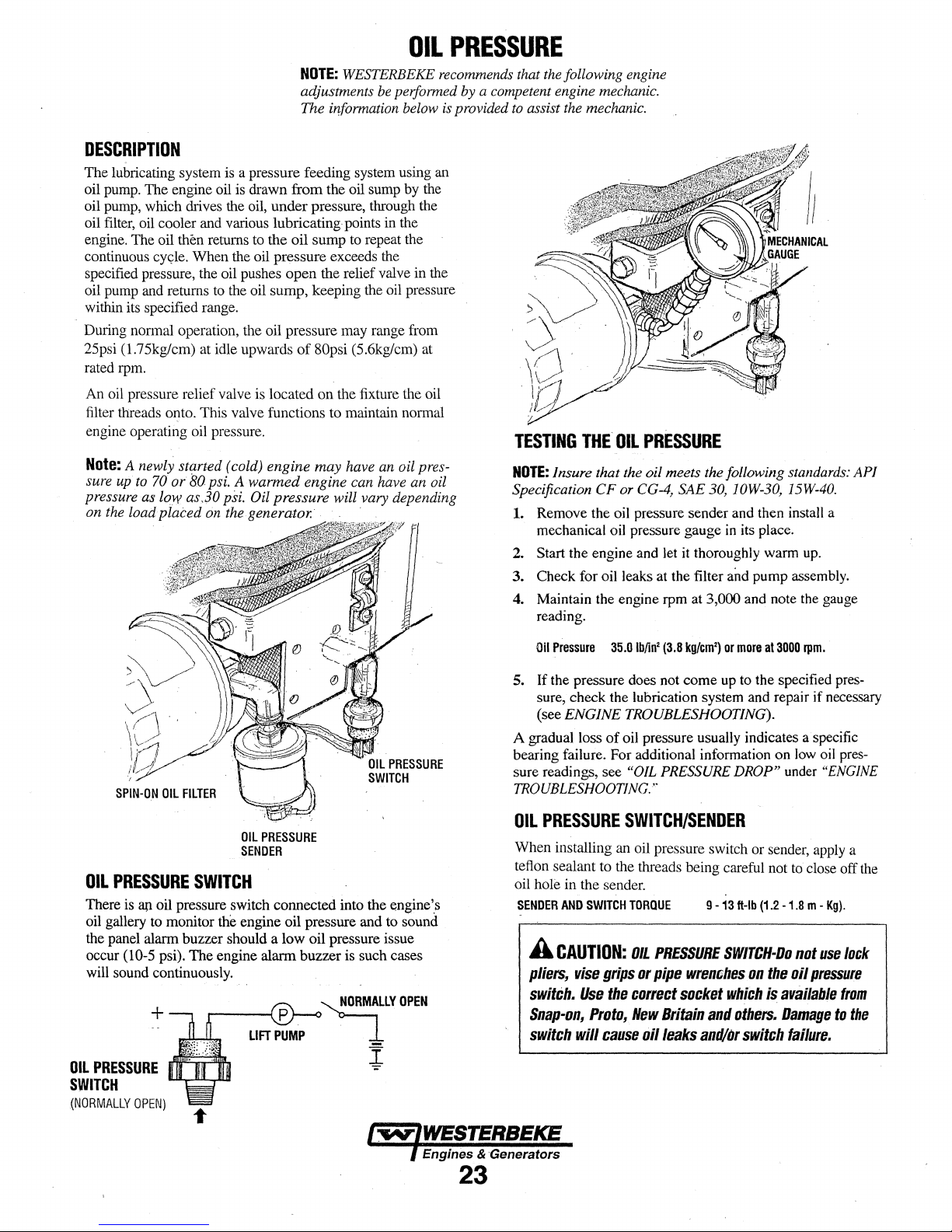
OIL
NOTE:
WESTERBEKE recommends that the following engine
adjustments be performed by a competent engine mechanic.
The information below is provided to assist the mechanic.
DESCRIPTION
The lubricating system is a pressure feeding system using an
oil pump. The engine oil
oil pump, which drives the oil,
oil filter, oil cooler and various lubricating points in the
engine. The oil
continuous
specified pressure, the oil pushes
oil pump and returns to the oil
within its specified range.
During normal operation, the oil pressure may range from
25psi (1.75kglcm) at idle upwards
rated rpm.
An oil pressure relief valve is located
filter threads onto. This valve functions to maintain normal
engine operating oil pressure.
Note:
A newly started (cold) engine
sure up to
pressure as
on
the
loadplaced
then returns to the
cy~le.
70
or
low as.30 psi. Oil pressure will vary depending
is drawn
When the oil pressure exceeds the
80
psi. A
on the generator. . . . .
from
under
oil
open
sump,
warmed
the oil sump by the
pressure, through the
sump to repeat the
the relief valve in the
keeping the oil pressure
of
80psi (5.6kg/cm) at
on
the fixture the oil
may
have an oil pres-
engine can have
an
oil
PRESSURE
TESTING
NOTE:
Specification
1.
2. Start the engine and let it thoroughly warm up.
3.
4. Maintain the engine
THE
Insure that the oil meets the following standards:
Remove the oil pressure sender and then install a
mechanical oil pressure gauge
Check for oil leaks at the filter and
reading.
CF
OIL
PRESSURE
or
CG-4,
SAE
rpm at 3,000 and note the gauge
30,
JOW-30,
in
its place.
pump
AP/
15W-40.
assembly.
SPIN-ON
OIL
PRESSURE
There is ap oil pressure switch
oil gallery to monitor the engine oil pressure and to sound
the panel alarm buzzer should a
occur
will sound continuously.
OIL
PRESSURE
SWITCH
(NORMALLY
OIL
(10-5 psi).
+
.......,........._.lllJll
OPEN)
FILTER
OIL
PRESSURE
SENDER
SWITCH
co1U1ected
low
The
engine alarm buzzer is such cases
into the e.ngine',s
oil pressure issue
~YOPEN
LIFT
PUMP
i
Oil
Pressure
5.
If
the pressure does not
sure, check the lubrication system and repair
(see
ENGINE TROUBLESHOOTING).
A gradual loss
bearing failure. For additional information
sure readings, see
TROUBLESHOOTING
OIL
PRESSURE
When installing an oil pressure switch or sender, apply a
tefion sealant
oil
hole
in
SENDER
AND
A
CAUTION:
pliers,
switch.
Snap-on,
switch
35.0
lb/in2
(3.8
kg/cm')
or
more
at
3000
come
up to the specified pres-
of
oil pressure usually indicates a specific
on
"OIL
PRESSURE
DROP"
under
...
SWITCH/SENDER
to
the threads being careful not to close off the
the sender.
SWITCH
vise
Use
Proto,
will
TORQUE
OIL
grips
or
the
correct
New
cause
PRESSURE
pipe
oil
wrenches
socket
Britain
leaks
and/or
9 -
13
ft-lb
(1.2
SWITCH·Oo
on
the
which
is
and
others.
switch
-1.8 m -
available
Damage
rpm.
if
necessary
low oil pres-
"ENGINE
Kg).
not
use
oil
pressure
tram
to
failure.
lock
the
Engines & ·Generators
23
Page 30

JNSTALLATION
Inns
popular
ler from
~ngine
NOTE:
tnstructions
tro
instBll,
WEsTBRBEKE's
tnstall
Contact
accessocy
the
engine
room
Refer
'simply
this
kit
yourWES'IERBEKE
to a more
bulkhead.
to
ENGINE
on
removing
remove the engine oil filter
remote oil filter kit
with
the oil filter
is
used
OIL
the
REMOTE
OIL
· (PN.032149)
to
relocate
the
convenient
CHANGE
oil
fil,ter.
facing
dealer
engine's
location
· ·
in
diis
111ll1'1U1Jlfor
and
as
shown.
down
as
illustrated.
for
more
infomlation.
such
thread
Always
FILTER
ROTE:
oil
as
fil-
an
on
incomct
A
iectly. .If
pass
from
failure. N there
Immediately
(OPTIONAL)
Westerbeke
i.nstall.ation
CAUTION:
valve
reaching
Pie
In
all
thB
the
and
is
.not
of
It
Is
flaws
Riter
engine
Is
no
check
responsible
the
Remote
vital
to
lnsf!lll
Jn
the
reverse
assembly
Gaoslng
all
pressaro
the
hose
for
engine
Oil
Filter.
the
direction,
will
prevent
an
lntemal
reading,
connections.
failure
oil
lines
the
the
engine
shutdown.
car-
ail
due
by-
to
·
lHE
OUT
CONNECTION
MUST
ATTACH
CONNECTION
REMOlE
TO
ATTllE
mL
FILTER.
Cylinder
Head
Crankshaft
HDIE
THE
IR
Pulley
APPLY A THIN
INSTALLING
THIS
TIGl!lEN
AN
ADDmllllAI.
CONTAC'IS
THE
Bolt
(See
MB
Nut
C;OllT.OI'
ctEAN
Kit
THREAD
BASE.
. •
(M10)
(M12)
the
Torauing
indicates
OIL
TO
THEO.RING
THE m ON,
AFTER
THEN
TllE
O.RJNO
3/4
TURN
TORQUE
Cylinder
Metric,
Bmm
WHEN
HANO
APPLY A THIN
GASKET
cqNTACTS
SPECIFICATIONS
lb-ft
47.0-57.9
83.2 -90.4
Head
Bolts
section
of
this
manual.)
thread
diameter.
108.5
-144.7
COAT
WHEN
INSTAWNQ,
'lHE
OF
CLEAN
DASE,
TIGHTEN
Kg-m
6.5 -8.0
11.5
15.0 -20.0
OIL
AFIER
IT
AN
-12.5
TD
lH£
RL'ltll
THE
ALTER
AODmDNAL
.
Main
Bearing
Cap
Nut
Connecting
Flywheel
Flywheel
Oil
Oil
Delivery
Nozzle
Nozzle
Glow
Bolt -with
Bolt -washer
Pan
Drain
Filter
Valve
Mounting
Holder
Plug
Rod
Plug
Holder
ard
Cap
Nut
separate
(injection
Bolt
Retaining
washers
attached
Nut
pump)
36.2 -39.7
23.1
-25.3
.
Engines & Generators
(or
tighten
83.2 -90.4
94.0-101.3
36.2-43.4
8.0 -9.4
firn11y
28.9
-36.2
10.8
-14.5
43.4 -57.9
10.8
-14.5
by
hand)
5.0-
5.5
3.2-3.5
11.5-12.5
13.0-14.0
5.0-
6.0
1.1
-1.3
4.0-5.0
1.5-
2.0
6.0 • 8.0
1.5-2.0
I
24
Page 31

TACHOMETER
TACHOMETER/HOUR
The
tachometer/hour meter used in propulsion engine instrument panels contains two separate electrical circuits with a
common ground.
other the tachometer. The hour
volts
alternator charging voltage supplied
on
the back
The
from
tachometer input terminal while the
the
alternator producing battery charging voltage
volts
The
a
fault
meter.
NOTE:
their battery (s) will stop charging. In such cases,
tachometer will stop functioning.
mast head
amperage
Hour
Check
terminals.
1.
Voltage
2.
Voltage
nections for fault. (Jump 12 volts
terminal to verify the operation.) .
Tachometer
Check
terminal and (-) terminal with the engine running.
1.
Voltage
tion
2.
AC
output voltage.
3.
Check for
4.
Check electrical connections
Tachometer
1.
Check for proper AC voltage between
2.
3.
Tachometer
1.
With a hand-held tach
pulley retaining nut
front crankshaft pulley rpm at idle.
of
the
tachometer circuit operates
one of the diodes in t!te alternator
DC.
following are procedures to follow
in
either
of
Many high output
or
running lights, this will result
draw.
meter
Inoperative
for
the proper DC voltage between ( +) and (-)
present - meter is defective - repair
not present - trace ( +) and (-) electrical con-
Inoperative
for
the proper AC voltage between tachometer input
present - attempt adjusting
access hole. No results, repair
voltage not present - check for proper alternator DC
AC
ground.
minal
to
alternator connection.
Sticking
nal
and (-) terminal.
Check for good ground connection between
minal and alternator.
Check that alternator is well grounded to engine block at
alternator pivot bolt.
Inaccurate
METER
One circuit operates the
meter
instrum~nt.
on
the two circuits in a tachometer/hour
DC
alternators when fully charged
To
voltage at tach terminal on alternator
from
on
the front
or
using a strobe type tach, read the
hour
meter and the
circuit operates on
to
the(+)
AC
voltage 6-8 volts, fed
and
supplied to the
engine
is running, and
13.0-14.8
when
troubleshooting
overcome
DC
meter
or
tachometer input ter-
of
this,
in
a small
or
to
meter
through calibra-
replace meter.
"tach
inp." termi-
meter(-)
the crankshaft
terminal
the
turn on a
replace.
( +)
DC
to
12
ter-
NOTE:
Current model tachometers use a coarse adjustment
dial to set the tachometer to the crankshaft pulley
calibrating screw
IDLE
SPEED
&
TACHOMETER
Checking
NOTE:
In a new installation having new instrument panels,
the tachometer may
engines rpm. This calibration should be checked in all new
installations.
1.
Warm
up
Remove
cloth and 'place a piece
pulley to facilitate use
2. Start and idle
3.
Aim
the light
confirm the engine speed.
tachometer reading. Adjust the tachometer in the panel
using the instrument coarse adjustment to calibrate the .
instrument reading to the closest
is showing.
bring the instrument to the exact reading as the photo_tach.
4. Adjust the idle speed
is
then
used
for
fine tuning.
LIGHT
CALIBRATION
ADJUSTMENT
CHECK
the
idle
speed
not
the engine to normal operating temperature.
any specks on the crankshaft pulley with a clean
the
engine.
of
the
Then
(New
Installation)
always be correctly calibrated to
of
suitable reflecting tape on the
of
a photoelectric. type tachometer.
tachometer onto the reflecting tape
Check
the instrument panel
R.P.M. that the photo tach
use the fine calibration adjustment
if
the engine speed is not within the
JUMPER
TACH
!NP
AG
VOLTAGE
rpms.
The
WIRE
(+)
to
spedfied value. • " i
!"
~
~
I
'"
;;;
-
;;
Oil
GAUG[
PlttSS.
WA.HR
Tt~P.
G.l.UGt
0~
e
g;
-
"
~
-
TERMINAL(l)
the
to
by
·
2.
Adjust the tachometer using an 2mm Allen head wrench
5/64 (2mm) through the calibration access hole in the rear
of
the
tachometer. Zero the tach and bring it to the rpm i
indicated by the strobe or hand tach (verify rpm at idle !
, , . I .
and
at
high speed). Ad1ust the tach as µeeded.
W'
WESTERBEKE--
Engines & Generators
25
"'
'"
- - - - - - - - - - - - - - - - - -
SHRl
SWJlCll
'"
'"
Pl\[·Sl.1.1\T
©
1
\
Page 32

WATER
HEATER
WATER
This engine is equipped with connections for the plumbing
engine coolant to transfer heat to an on-board water heater.
The water heater should be mounted in a convenient location
either in a high or low position in relation to the engine, so
that the connecting hoses from
run in a reasonably direct line without any loops which might
trap
HEATER
air.
INSTALLATIONS
the heater to the engine can
··
- ·
~'
./
,/
REMOVE
,,,~
BY-PASS
WHEN
WATER
THERE
HEATER
of
IS
NO
The pressure cap on the engine's manifold should be
installed
coolant. Finish filling the cooling system from the remote
tank after the system is filled and is free
good coolant circulation. During engine operation, checking
the engine's coolant should
not at the engine
heater to the remote expansion tank should be routed and
supported so it rises continuously from the heater to the tank,
enabling any air in the system to rise up to the tank and out
of
the system.
~OSECONNECTIONS
/Hoses
/
should.
rise.
continuously from their low. point at the
heater to the engine so that air will rise naturally from the
1
. heater
to
the engine.
then
an
air bleed petcock must
ting
on
the heater for bleeding air while filling the system.
If
trapped air is able to rise to the
be
installed at the higher
he~ter,
fit-
aftt~r
the engine's cooling system is filled with
of
be
done
at
the remote tank and
manif!)ld cap.
The
hose connection from the
REMOTE EXPANSION
TANK (
MAINTAIN
air and exhibits
WESTERBEKE)
COOLANT
LEVEL
NOTE:
If
any
portion
engines own
remote
expansion
circuit
to
become
tank
into
the
connections
single
engine's
nient
remote
fill
point.
the
remote
serves
recove1y
REMOVERETU
BEND.
for
line
up
return.
location
expansion
The plastic coolant recovery tank
expansion tank kit
the same function. Remove and store
tank
of
the
heating circuit rises above
pressure
heater
to
so
if it
cap,
then
tank
(Kit
#024177)
the
highest point.
circuit,
choosing
the
return.
Tee
the
tank's
location and the other back
Install
the
remote
the
coolant level can easily
tank
will
now
has
been
already installed.
a pressurized (aluminum)
must
be
installed
Tee
the
remote
expansion
the
higher
of
the
at
the
heater,
and plumb a
expansion tank
s'erve
as a check and system
is
installed, since this tank
WATER
in a conve-
be
checked.
is
not used when
the
plastic
HEATER
LOCATED
the
in
two
to
the
the
The
BELOW
THE
ENGINE
.WATER
HEATER
NOTE:
An air bleed petcock is located on
heat
exchanger.
coolant system
Open this petcock when filling
to
'allow air
Close tightly after all the air
' A
CAUTION:
wear
proper gloves.
Beware
in
the
is
of
LOCATED
exchanger
removed.
the hot
ABOVE
the
engine
THE
ENGINE
engine's
the
engine's
to
escape.
coolant
-
Engines & Generators
26
Page 33

DESCRIPTION
The
starting
system
and
starter
button.
When
the
starter
button
current
flows
and
energizes
energized
into
to
serves
flywheel.
To
pinion
is
engine
motor
Once
ping
contact
flow
magnetic
plw1ger
from
the
reach
to
prevent
gear
splined
may
itself.
the
the
with
of
electricity
its
coil
becomes
coil,
and
closes
the
starter
push
that
drunage
incorporates
to
the
starter
speed
the
started
button
activation
the
battery-to-start
is
:fields
and
is
released,
engagement
motor.
starter
to
of
the
its
includes
interrupted
with
the
battery,
on
the
iustrument
the
starter's
fill
electromagnet,
a set of
contacts
At
the
same
pinion
to
mesh
the
starter
motor
an
over-running.(one-way)
annature
rotation
is
the
struier
movement
shaft.
of
released,
solenoid.
cables
to
ceases
the
engine
the
the
The
the
also
starter
panel
solenoid
which
which
time,
the
with
when
The
rotation
pinion
but
current
plw1ger
by a coil
starter.
its
rotation.
pulls
the
flywheel.
SOLENOID
STARTER
.
motor,
solenoid,
is
depressed,
coil.
The
pulls
the
plunger
allow
high
current
plunger
the
the
not
flow
is'
spring,
This
starter
teeth
engiue
clutch
of
the
the
ceases,
pulled
weakens
As
the
drive
also
on
the
starts,
which
running
starter
stop-
out
of
and
the
the
solenoid
gear
·
MOTOR
PN.053295
SOLENOID
IGNITION
TERMINAL
TO
CONTROL
PANEL
the
To
test
of
the
small
Use a screwdriver,
ignition
the
solenoid.
If
the starter cranks, the fault
If
the
solenoid
motor
the
ignition
temrinal
tenninal
is
probably
circuit,
don't
to
the
clicks
faulty.
\
locate
studs
and
touch
positive
but nothing
the
is
wired
the
blade,
battery
lies
else
ignition(s)
to
the
to
jl,U11p
connection
with
the
happens,
tenninal
ignition
from
terminal
ignition
the
(it
is
circuit).
that
on
circuit
starter
one
MO
TO
ii
TYPICAL
STARTER
REFER
DIAGRAM
MOTOR
TO
THE
IN
WIRING
THIS
MANUAL
TROUBLESHOOTING
Prior
to
testing,
make
certain
the
ru1d
that
the
struiing
clean
and
tight
connections
To
check
the
never
more
than
the
wires
and
resistance.
Using a multimeter,
stud
If
you
on
the
read
Repair
strut
Pay
on
the
wiring,
10
tennmals
or
solenoid
12
volts,
system
particular
engine
block.
try
cranking
seconds
looking
replace
test
the
and
the starter
wiring
attention
at a
any
voltage
the
ships
batteries
co1mections
to
the
starter
time,
then
for
wann
trouble
between
engine
is
faulty.
the
for a few
run
spots
spots.
block
are
at
(terminals)
ground
your
that
the
positive
(grollild).
full
charge
wire
seconds,
hand
along
indicate
terminal
are
SOLENOID
IGNITION
TERMINAL
TO
CONTROL
.
PANEL
If
nothing at
Check
the
battery
connections.
A
WARNING:
fly
when
space
is
gasoline.
all
happens the
isolation
It
is
also
jumping
fI:ee
of potentially
switch
possible
There
will
terminals.
solenoid
and
inspect
that
the
solenoid
be
arching
Be
certain·the
explosive
isn't
getting
the
wiring
is
defective.
and
sparks
engine
fumes,
current.
will
especially
Engines & Generators
27
Page 34

IGNITION
TERMINAL
Test
again
screwdriver
screwdriver
would
cause a short.
A
WARNING:
starting
screwdriver.
by
jumping
blade
blade
current
the
firmly
to
touch
There
should
two
large
between
the
solenoid
will
be
flawing
terminal
the
be
studs.
studs.
Do
o~
starter
arching
thru
STARTER
Hold
the
not
allow
the
casing,
this
as
the
full
the
blade
of
the
MOTOR
SERVICE
Westerbeke
serviced
If
replacing
certified
standards.
TO
1.
Disconnect
2.
If
starter
3.
Label
wires
4.
Remove
5.
Remove
will
uses a standard
or
rebuilt
the
starter
for
marine
If
in
doubt,
REMOVE
the
necessary,
motor.
and
to
have
remove
disconnect
touch,
the
starter
the
starter
to
be
at
any
motor,
use.
Automotive
contact
FOR
SERVICE
negative
any
tape
over
mounting
from
turned
ma1ine
starter
starter
motor
make
certain
your
WESTERBEKE
battery
cable.
components
the
wiring
from
the
terminals).
bolts.
the
engine.
to a different
motor
automotive
the
starters
do
to
gain
the
h1
some
angle
which
service
new
not
full
starter.
cases
to
clear
can
be
center.
motor
is
meet
USCG
dealer.
access
to
the
(Do
not
allow
the
starter
obstructions.
If
the
starter
If
the
starter
If
no
arching
NOTE:
Starter
the
pre-engaged
engages
screwdriver
motor
provide
magnetic
the
the
without
the
field
solenoid
spins,
fails
occurred.
motors
model,
starter
to
bypass
engaging
power
for
are
bad.
the
to
motor
to
the
the
solenoid
spin,
the
There
are
either
the
solenoid.also
to
the
solenoid
the
flywheel.
solenoid.
arm
to
motor
is
the
flywheel
move
is
faulty.
is
no
juice
inertia
tjpe
on
such a starter
Turn
Hopefully
even
though
probably
reaching
or
pre-engaged.
moves
an
of
the
engine.
the
starter
it
will
the
faulty.
the
solenoid.
arm
that
Using
will
run
switch
create
contacts
In
a
the
on
to
enough
inside
Engines & Generators
28
Page 35

DC
ELECTRICAL
ALTERNATOR
The
charging system consists
with
a voltage regulator, an engine DC\viring harness, a
mounted DC circuit breaker and a,battery with connecting
cables.
Because
electronic voltage regulator is very compact and
internally or
of
on
the back
the use
of
a DC belt driven alternator
of
integrated circuits (IC's), the
of
the alternator.
~
is
mounted
SYSTEM
1.
Start the engine.
2. After the engine has run for a
starting battery voltage at
multimeter set on DC volts.
a.
If
the voltage
tor is working; omit Steps 3
to "Checking the Service Battery"
b.
If
the voltage remains around
exists with either the alternator or
continue with Steps 3 through
is
the
increasing
few
minutes,
battery
terminals
toward
14
tlu-ough 8 and
on
12
volts, a
the
8.
measure
volts,
the
go
the
next
problem
charging
using
alterna-
directly
page.
circuit;
the
a
#10
RED
,AT
STARTER
51A
ALTERNATOR
Refer
to
the
this
manual
and
their
wiring
112
BLACK
the
alternator
or
the
staJ.ting
TO
AT
STARTER
can
be~ome
has
or
with the alternator.
voltage regulator
battery is not discharged
If
the-alternator is charging the
cooled
if
a problem
very
down.
If
is
faulty,
it
is
GROUND
ALTERNATOR
A
WARNING:
hot.
Do.not
Use
this
exists
with
detennined that the alternator
have
a qualified technician check it.
The alternator charging circuit charges the starting battery
and
the service battery. An isolator with a diode, a solenoid
or
a battery selector switch is usually mounted in the circuit
to
isolate the
along
with the service battery.
starting battery but not the service battery, the problem
the
service battery's charging circuit and not with the altema·
tor.
Testing
TROUBLESHOOTING
A failed alternator
touch
until
troubleshooting section to detennine
the charging circuit
batte1ies
the
Alternator
so
BATTERY
CONNECTOR
WIRING
for
the
alternator
connections.
is
in
MULTIMETER-~e
(SHOWN)
DIAGRAMS
IN
models
TESTING
THE
STARTING
BATTERY/ALTERNATOR
(ENGINE
3.
Turn
Ensure that the battery
connections are tight and
A
charging
switch
4.
If
a battery selector switch
ensure that it is on the correct
5.
Tum
6.
Check the battery voltage.
tion, the reading should be
RUNNING)
off the engine. Inspect
CAUTION:
circuit,
when
tlie
' .
on
the ignition switch, but
Lenninals
To
avoid
never
engine
.
-::-
all
clean.
damage
shut
oft
is
running!
is
in
setting.
If
the battery
12
to
mm
COM
GROUND
wiring,
and
and
the
engine
to
the
the
engine
the charging
do
not start
is
13
volts.
connections.
ground
battery
battery
circuit,
the
engine.
in
good
condi-
A
CAUTION:
that
everyone
sheaves
A
DC
applications.
isolate
before
made
and
WARNING:
and
AC
DC
performing
without'a
Before
is
clear
belts
circuits
Always
and
AC
proper
starting
of
moving
during
test
procedures.
When
testing
are
often
mixed
disconnect a shore
converters,
DC
testing.
and
No
knowledge
the
parts!
with a multimeter:
AC
engine
Keep
together
shut
down
tests
of
AC
circuits.
make
away
in
marine
power
cord,
the
should.be
certain
from
TESTING
engine
ALTERNATOR
(IGNITION
Engines & Generators
29
THE
VOLTAGE
ON -ENGINE
OFF)
-
'GROUND
Page 36

7.
Now
check
minal
(B+)
the
alternator
tor
is
in
the
neither
of.the
between
connections -look
the
the
voltage
and
ground.
will
be
circuit
above
alternator
between
If
the circuit
the
same
as
the
alternator voltage
is
true,
a problem
and
the
battery.
for
an
opening
DC
ELECTRICAL
the alternator output
is
good,
the
voltage
the
battery,
in
MULTIMETER
will
exists
Check
the
charging
or
be
in
all
if
an
zero.
the
circuit
the
cra:5]
ter-
isola-
If
circuit.
at
SYSTEM
Checking
Check the voltage of the service battery.
have a voltage between
running. If
charging circuit. Troubleshoot the service
circuit
isolator, battery switch,
the
Service
not,
there is a problem
by
checking the wiring
Battery
13
and
14
volts
in
and
and
the battery itself.
the
connections,
TI:ris
when
service
battery
battery
the
engine
battery
charging
the
should
is
solenoid,
TESTING
BATTERY/ALTERNATOR
(ENGINE
8.
Start
alternator
The
should
is
service
NOTE:
voltmeter to ensure
at the
tery voltage
Ij
wiring
THE
STARTING
RUNNING}
the
engine
again.
oµtput
and
voltage
over-
12
reading for a properly operating alternator
be
between
or
under-charging,
facility.
Before removing the alternator
EXC
volts is not present
and
13.5
tha.t
tenninal if the previous test showed only bat-
at
the B output terminal.
look
for
·
Check the voltage between the
ground.
arid
14.5
volts.
If
your alternator
have it repaired at a reliable
for
repair, use a
12 volts
at
breaks and
the
DC
excitation
EXC
tennina~
poor
connections. •
trace the
is
present
MULTIMETER
GROUND
A
CAUTION:
diodes,
when
do
perfonnlng
·e
not
use a high
00J
COM
To
avoid
tests
damaging
voltage
on
the
alternator
TESTING
BATTERY
THE
(ENGINE
the
alternator
tester
(I.e. a megger}
charging
SERVICE
RUNNING)
circuit.
12
VOLT
DC
The
engine
shown
on
diagrams
electrical
A
CAUTION:
circuit,
the
engine
however,.
engine's
CONTROL
has
a
12
the
wiring
when
troubleshooting or when servicing the
system.
To
never
shut
Is
running.
to
avoid
electrical circuit. ·
CIRCUIT
volt
DC electrical control circuit that
diagrams that
avoid
damage
off
the
Shut
electrical
engine
off
the
shorts
follow.
to
battery switch
engine
BAnERY
The
recommended
starting
Cranking
12
volt
Amps
"dedicated"
DC
control
(CCA) rated.
battery used
circuit should be
the
when
Refer
battery
working
for
is
to
these
DC
charging
while
battery switch,
on
the
the
engine's
800..1000
Cold
Engines & Generators
Battery
Review the manufacturer's recommendations
establish a systematic maintenance schedule
starting batteries
Care
and
house batteries.
D Monitor your voltmeter for proper charging
operation. ·
D Check the electrolyte level
hydrometer.
D
Use
only
distilled water
level.
to
and
bring
D Make certain that battery cable connections
tight
to
the battery posts
D .l(eep your batteries clean
A
WARNIN.G:
cause
severe
protective
Sulfuric
bums
gear.
on
acid
skin
(and
and
and
to
free
In
damage
30
and
then
for
your
engine's
during
engine
specific gravity
~lecb:olytes
your engine).
of corrosion.
lead
batteries
clothing.
with
to a proper
are
clean
can
Wear
a
and
Page 37

PROPULSION
•
0
11
:
'J
~
- r ·---,
....
-------i,,-•~1-,..------..~\!:'.!.·1----~---
._---11------,-r--,,~-~--~
8A!
KIT
,._
IGH
Sf.UT
(
Sot.
I I
1 I ·
•
r-+--1-+------•
PRtME.lT
SlARJlR
•
r.;-M
--·-··-
.t.LTtRIUl'OJl
GLOW'LUGS
CURiltHl
·-··OwK(iUs["o1
O,P,
S£HD[A
l
HT
run
..
PUKP
sol.
-·•·
11
MUI I
ADMIRAL
PANEL
TACHOfol(TCR
S
GHO
ENGINE
rmrrs:
I.
THIS
PRODUCT
SlARTER.
SNIJ't
DOWN.
[NGIN[
ARE
l-
UI
OR·OH
OISCQMN[Cl
WITH A CONTINUOUS
SWfTCU
SUOULD
l.
TH[
Pl!Ht
L
HIE
GRAY
'''LT.
DlV
U
tt.t
GIA
CNOl
US(DJ
MAl(
CONN[ClOR~
ON
THU
tll
ORN
tH.CHl 4
WIRING
IS
f>kOrcc1co
[<((SSIY£
ThE
SUILD[Rl~fR
IN'SU.ll£0
SWITCH
Stt0ULO
THC
SAlltRT
RATING Of
HOT
8(
\llltE
Ill
Pl.UG ?
WJR[
AT
PUIG
UC
PINK
RED
Ui]*
SID[
-..:
CURR[Wl
TO
PR(Y[llT
8£
lit
UStO
IS
2 IS
R[GUlATOll
t~Ol
totATIOHI
SCHEMATIC
BY
..
MANUAL
RES['t
8£
OR
AND
ANO
-
IHE
SUR(
en•tEH
8£TWE£H
AHD
8R(AI
SHOUtO
SHOUlO
CIRCU-lf
BR[U[R
'IH/rT
THC
WH[N
voe
THC
bE
BE
n.tcnttt.Al
LEAVING
c IRCUIT •
Will
"MUST
lffSUll(D
AN
[M[RG(NC'r
llS
ro
MAK(
UNUst:D
utruuo
IU
c•USC
C-OffUCl
AMPS n 11
8Sitl
#039144
UR.EAM[CI
10
TRIP
TM(
IHSTRUJt(lfT
8AfT[RY
AflO
lH(
Will
S(RV[
INSutATCD.
IHSULA.TfO.
LOCUC:O
••o
me
PAH[l,
OEYtC[S
SUJff[R
80-'L
nus
CAPTAHI
AOMUtAl
NOR
[RGI~[
Wlfl1NG,
ANO
TO
A SWITCH
ruNCTION
PA.ff((
PAtf[l
TM{
WILL
ANO
~{,f.'f'AlU
,.
nus
onn.
OHL
y.
l 18
ACU
fl·.J
STAltl
SW.
"
L-----f--'{S
51
STANDARD
SSC.
828,
l'f·lt
lf
hC"OM[TtR
ND
LAMP
HST
SW.
CAPTAIN
03
PANEL
AMP.
ALTERNATOR
AL
lERNAToR
638,
&JC.
1088.
&
108~.
&4A.
...
,
ON
718.
THE
UCtTUf(f~
uncu
•
18
RCD
ii 10
ORN
11 ( GRA
MAL[
•u
OH
LESTER
CONlf[ClOR
nus
SIDt
ft!IH ~
ALT
114
100
..
,
•
BRN
AMP
8LU
ALT ©
R[D
Wltl
DLU
Non: .
WIR[
lo
U['
roR 8Al1£RY
U1'GRAD[O
41UTCRMCHT
to
AN
8 GAUGt
WILL H[(O
r110M
JO
GAUGE
REGULATOR
tM~OL
lOCATIOMI
.
Page 38

WIRING
DIAGRAM
@denotes
#03906
oil
pressure ala'"!. c;ircuit resistor
off
preheat solenoid I terminal.
,-----
1
SEE
NOTE
Z
I I
i~1
I
I
-'
·1
I
I
+lufJ
~~
.lillW
When connecting the instrument harness
to the engine harness use Di-Electric grease.
at
the connection.
harness plugs tightly with a Tywrap.
the
After
connecting, fasten
I
i~---
I
I
I
I
I
I
I
...
'--------------------------------~
#39144
sz
:
..
ptt;.•
; - .
p
+
ALARM
C
.Ull[R
ADMIRAL
PANEL
--j
I
I
I
I
I
I
I
I
I
I
I
I
I
I
I
I
.__~·~·~·~·~••:....-~~~~~~~~~~-'
I
114
PNK
llfT
••
PUMP
~
.
~
m
.
.
r--
'
I
I
I
I
I
I
I
-
.
I
f
f
I
I
I
I
I
I
I
~
t
I
I
l - - - - - - - - - - - -
...................
CAPTAIN
·PANEL
ALT.
L
..
....
OJ'.
LAMP
TACHOMETl!ll
......
-- -- -
0
II
ORN
tll
8Llt
•1a-
au
.ia
BL!l.
=~'-'"••..;Ill=·-~~=-=~--~~-~-~---~--~
32
I
I
I
i
I
I
I
I
I
I
I
·I
I
I
I
I
_,
Page 39

ENGINE
TROUBLESHOOTING
The following troubleshooting table describes certain problems
relating to engine service, the probable causes
of
these problems,
and the reconunendations to overcome these problems.
No
panel
Indications;
not
working
PREHEAT
START
engagement.
Engine
start.
Engine
Battery
Battery
(key
button
button
cranks,
can't
be
runs
down.
not
charging
Problem
fuel
switch
is
depressed).
is
depressed,
but
does
stopped.
pump
is
ON
not
and
no
is
starter
1.
Battery
20-amp
2.
3.
Loose
Connection
1.
(Hydraulic
Gear
2.
Faulty
3.
Faulty
4.
5.
Loose
Low
6.
1.
Faulty
Preheat
2.
Low
3.
Disconnected
1.
Oil
pressure
1.
High
2.
Low
3.
Poor
4.
DC
alternator
5.
(tachometer
DC
alternator
1.
2.
Alternator
Probable
switch
not
circuit
breaker
connections
to
solenoid
Transmission)
shift
not
in
switch.
solenoid.
battery
connections.
battery.
fueling
system.
solenoid
battery
power.
fuel
switch.
resistance
resistance
battery
connections.
not
not
drive.
Cause
on.
tripped.
between
faulty.
neutral.
faulty.
shut-off
leak
to
ground.
leak.
charging
operating).
NOTE:
The engines electrical system is protected by a 20
ampere manual reset circuit breaker located on a bracket.
The preheat solenoid
is
mounted on the same bracket.
Verification/Remedy
1.
Check
switch
and/or
battery
connections.
2.
Reset
breaker;
if
breaker
trips
again,
shorts
to
and
secure
(see
NEUTRAL
at
the
Bleed
filters
start
lever.
lights
pressure
(0 -.25
Remove
rise
battery
belt
tension,
of
the
DC
output
terminal.
check
ground.
with
solenoid
air
from
and
bleed
batteries.
Pull
lever
are
activated
switch.
amp)
connections
to
locate
for
loose
test
alternator
should
with
voltmeter.
the
panel
cable.
circuit
3.
Check
Check
1.
2.
Gear
WARNER
3.
Check
4.
Check
terminal.
5.
Check
6.
Check
1.
Check
1a.
Check
1b.
Fuel
fuel
2.
Check
3.
Switch
3a.
Replace
1.
Check
the
1.
Observe
is
2.
Check
lines.
after
3.
Check
4.
Check
corrosion
5.
Check
SERVICE
1.
Perform
2.
Check
for
volts
and
check
the
plug
connection
connection.
shift
must
TRANSMISSIONS)
switch
with
that
12
volts
battery
connections.
battery
charge
that
fuel
valves
for
air
in
filters
clogged.
system.
solenoid.
to
combine
batteries.
connection
fuel.
if
gauges
not
running.
Test
wiring.
Insert
(Do
not
start
short
is
located.
all
wires
cable
connections
connections,
MANUAL.
DC
voltage
drive
belt
loose
connections.
are
present
circuit
be
in
neutral
ohmmeter.
are
present
state.
are
fuel
system.
Replace
house
at
shut-off
and
panel
the
sensitive
engine.)
for
temperature
check
check
tension;
Check
at
the
for
open.
and
oil
at
alternator
Exe.
preheat
solenoid
tie
wrap.
SWITCH
activation
fuel
system.
air
from
back
to
close
when
meter
in
and
the
fault.
connections,
alternator.
turn
freely.
Ensure
under
off
engine
battery
replace
See
Check
12
lw,WESTERBEKE
~nalnss
& Generators
33
Page 40

Engine
slows
Engine
overheats/alarm
.
Engine
alarm
Engine
(Low
or
Exhaust
alarm
High
smoke
Problem
and
stops.
sound
pulsates.
sounds
continuously.
Volumn)
problems
sounds.
ENGINE
Probable
1.
Fuel
lift
pump
failure.
Oil
switche
2.
3.
4.
5.
1.
2.
1.
2.
1.
1.
2.
3.
or
Fuel
20
Water
Raw
Coolant
Loss
Oil
Faulty
Blue
White
Black
and/or
disconnected.
starvation.
Amp
circuit
breaker
in
fuel.
water
not
circulating.
not
circulating.
of
oil.
pressure
switch.
Resistor.
smoke.
smoke.
smoke.
TROUBLESHOOTING
Cause
wiring
tripping.
loose
1.
Fuel
pump
2.
Inspect
Inspect
3.
Check
4.
Check
Ensure
cause
5.
Pump
bleed
1.
Raw
2.
Obstruction
2a.
Thermostat -remove
Replace
2b.
Loss
for
2c.
Broken
2d.
Air
bleed
1.
Check
oil
2.
Replace
1.
Resistor
1.
Incorrect
1a.
Crankcase
through
2.
Engine
2a.
Faulty
3.
Improper
3a.
Fuel
insufficient
exhaust
3b.
Improperly
3c.
Lack
ventilation.
3d.
Overload.
Verification/Remedy
lift
pump
should
with
spare.
wiring
for
switche
fuel
for
breaker
tripping.
water
fuel
water
of
coolant -check
leaks.
or
leak
in
air.
dipstick,
drain
is
injector
burn
of
short
for
proper
supply,
fuel
high
DC
amperage
is
not
from
fuel
system.
pump
failure.
at
raw
water
thermostat.
loose
belts -tighten/replace.
system;
run
Add
coolant
look
connection.
pressure
Preheat
of
engine
is
overfilled
exhaust).
cold.
or
incorrect
of
fuel.
air
for
proper
check
timed
injectors
for
hose
oil
off.
grade
the
running
grade
incomplete
system;
air -check
make a distinct
circuits
operation.
valves,
overly
tank(s);
Check
intake
and
test
hoses,
engine
as
needed.
oil
leaks
switch.
solenoid 1 terminal
oil.
with
engine
injector
due
to
combustion
air
intake).
or
air
intake
ticking
and
loose
connections.
fuel
lift
pump.
draw
during
sensitive
change
impeller -replace.
or
in
and
high
valves,
and
operation.
to
heat
filters
raw
water
hot
water.
hose
clamps,
open
the
pressure
at
oil
filter
and
(1 K ohm
oil
(oil
is
timing.
back-pressure
(check
or
poor
air
filter.
Check
sound.
Replace
which
would
and
filter.
drain
plug,
cap
at
value).
blowing
out
in
exhaust
for
restrictions
compression.
for
proper
etc.
to
or
in
TROUBLESHOOTING
If
the gauge reading is other than what is normally indicated
by the gauge when the instmment panel is energized, the first
DC
step is to check for 12.volts
and the Negative (B-) terminals
Assuming that there is 12 volts as required, leave the
instrument panel energized and perform the following steps:
1.
Disconnect the sender wire
gauge reads zero, which
situation.
2. Remove the wire attached to the sender terminal at the
sender and connect it to ground.
full scale, which is the normal reading for this situation.
between the ignition (B+)
of
the gauge.
at
the gauge and see
is
the normal reading for this
See
COOLANT
if
the gauge reads
TEMPERATURE
if
the
lw,WESTEllBEKE
Enalnss
34
AND
OIL
If
both
of
the above gauge tests are positive, the gauge is
undoubtedly
PRESSURE
OK
and the problem lies either with the
GAUGES
conductor from the sender to the gauge or with the sender.
If
either
of
the above gauge tests are negative, the gauge is
be
probably defective and should
Assuming the gauge is
OK, check the conductor from the
replaced.
sender to the sender terminal at the gauge for continuity.
Check that the engine block is connected to the ground.
/,.
Generators
Page 41

ENGINE
ADJUSTMENTS
ADJUSTING
1.
Loosen the locknut on the idle adjustment bolt
fuel injection pump.
2.
Adjust the bolt so that the throttle control lever will hold
the engine at a quiet idle.
3. Tighten the locknut.
4. Race the engine several times to ensure the idle speed
remains as set.
NOTE:
tachometer
a
mechanical
crankshaft.
STOP
CONTROL
THE
IDLE
SPEED
Should
the
engine
rpm
readings
as
shown
or strobe-type tachometer at
See
TACHOMETER.
ENGINE
STOP
CABLE
POSfTION
STOP
.
ENGINE
CABLE
CONTROL
DOWN.
be
in
question, verify
at
the instrument panel with
the
THE
ADJUSTMENT
SET.
ADJUSTMENT
SO
THAT
WILL
THE
SHUT
THE
on
the
engine
HIGH
.
the
SPEED
rs
FACTORY
3/8'
TO
1/2'
DEFLECTION
Adjusting
1.
Loosen the alternator adjusting strap bolt and the base
mounting bolt.
2. With the belt loose, inspect for wear, cracks and frayed
edges.
3. Pivot the alternator
or
4. Tighten the base mounting bolt and the adjusting strap
bolt.· ·
5. Run the engine for about 5 minutes, then shut down and
recheck the belt tensions.
~WARNING:
drive
Belt
Tension
on
the base mouhting bolt to the left
right as required, to loosen
Never
attempt
belt's
tension
l(lhi/e
the
or
tighten.
to
check
engine
or
adjust
is
.in
operation.
the
RECOMMENDED
Model
35BffHREE
38B/FOUR
43B/FOUR
NOTE:
What ever style propeller
load
the
engine
RPM
of
3600 + 0 -
in
forward gear for
RPM
RANGE
Idle
RPM
800-1000
750-
900
750-
900 2500 - 3000 3500 - 3600
it MUST allow
100
the
Cruise
25002500-
is
being
the
engine
at full open tlirottle while underway
correct propeller load on then
engine.
Max.
3500-
To
properly
RPM
its
3600
rated
RPM
3000 3500 - 3600
3000
used.
to
Peach
lwlWEBTERBEKS
) Engines &
BELT
INSPECTION/MAINTENANCE
Proper inspection, service and maintenance
is important for the efficient operation
Drive Belts under MAINTENANCE
(see
Drive belts must
will not provide proper alternator charging and will
eventually damage the alternator. Drive belts that are too
tight will pull the alternator out
alternator to
tension can also cause rapid wear
service life
presence
in high operating temperatures and tachometer variations.
The drive belt is properly adjusted
no less than 3/8 inch (lOmm) and no more than
(12mm) as the belt is depressed with the thumb at the
midpoint between the two pulleys on the longest span
belt. A spare belt
of
be
wear
out prematurely. Excessive drive belt
of
the coolant pump's bearing. A slack belt or the
oil on the belt can cause belt slipping, resulting
or
G~n.,ratOi'S
35
of
the drive belts
of
your engine
SCHEDULE).
properly .tensioned. Loose drive belts
of
alignment and/or cause the
of
the .belt and reduce the
if
the belt can be deflected
l/2
inch
of
belts should always
be
carried on board.
·
the
Page 42

ENGINE
NOTE:
WESTERBEKE recommends that the following engine adjust-
ments be performed by a competent engine mechanic.
below is provided to assist the mechanic.
Torquing
Tighten the cylinder head bolts according to the sequence
shown. Make
Before applying the specified torque to the bolt, loosen it
1/4 procedure according to the numbered sequence shown.
NOTE:
Cylinder
sure the engine is cold when this is done.
112
of
a turn and then apply the torque. Follow this
MJO
Head Bolts require a 14mm socket.
M12 Head Bolts require a 17mm socket.
~Qad
Bolts
(W
358
Three
Engine
ADJUSTMENTS
The information
#4, #5, #6, #7, #8, #9, #10 and
Bolts
between 83.2 - 90.4 lb-ft (11.5
Bolts #1, #2, and #3 are tightened between
(6.5
- 8.0 kg-m) wet.
Q<;
ENGINE
•
FRONT
02
#11
- 12.5 kg-m) wet.
0
7
4
0
01
are tightened
47.~
- 57.8 lb-ft
0
5
6
0
03
0
11
8
0
VALVE
358
Adjust
are
engine, (1-3-2). Tightening
specified
pages).
1. Pull off the
2. Adjust the valve clearances at
3. Align the timing mark
4. Next the No.3 cylinder, turn the crankshaft clockwise
CLEARANCE
THREE
adjusted
take
for each
stroke. Remember the engines firing order is 1-3-2. You
may find that tuning the engine's crankshaft is more
easily accomplished when the engine's glow plugs are
removed before the crankshaft is rotated.
mark pulley indicated for cylinder #1 (the one nest to the
three injection timing marks). In this position, the No.I
cylinder is at its top
compression stroke. Check both the intake and exhaust
valve
specified clearance, adjust by means
screws. Remember to align the timing marks properly,
not the valve may
on the position
valves for this cylinder
240° so the TDC mark for the No.3 cylinder
crankshaft pulley is approximately at the position shown
in the illustration. Adjust the intake and exhaust valves for
cylinder No.3. Be sure to check the valves for this cylinder as they both should
5. Last is
240° to position the
approximately at the positfon shown in the illustration:
Adjust the intake and exhaust valves for cylinder No.2.
Be sure to check the valves for this cylinder as
should
Adjust
(0.25
mm)
valve stem.
ENGINE
the
valve clearance
by
torque
off
the rocker cover bolts and the rocker cover.
cylinder when they are on their compression
clearances for this cylinder.
~e
No.2 cylinder, turn the crankshaft clockwise
be
closed.
each
valve's
feeler gauge between
ADJUSTMENT
when
the
engine is cold. Valves
the
cylinder
before
air breather pipe from the rocker cover and
be
of
the cam lobe.
clearance
in
the
firing
order
of
the
the
cylinder
adjusting
TDC
on
the gear case with the timing
Timing mark while dead center
pushed
me
up
as
they both should be closed.
be
closed.
mark on the crankshaft pulley
by
head
bolts to
the
valves (see previous
(Top Dead Center)
If
the· valves have no
of
the adjusting
by the piston, depending
Be
sure to check the
on
the front
theyboth
inserting
the
rocker
a·
0.010
arm
and
in
the
on
the
if
its
TDC
MARK
CYLINDER.
NO
VALVE
.2
CLEARANCE
ADJUSTMENT
l-w-IWEB7ERBEKE
l
EnalntJS
&
Generators
36.·
Page 43

ENGINE
NOTE:
WESTERBEKE recommends that the following engine adjustments be peiformed by a competent engine mechanic.
below is provided to assist the mechanic.
ADJUSTMENTS
The
information
Torauing
W
388
Tighten the cylinder head bolts according to the sequence
·
shown in the illustration. Make sure the engine is cold when
this
loosen it
: this procedure according
Bolts
between 83.2
Bolts
(6.5 -8.0
VALVE
W
388
Adjust
Tightening
before
1.
Pull
2.
for
3.
4. After adjusting the valves for cylinder No.I, rotate the
5.
6.
Cylinder
FOUR
is
done. Before applying the specified torgue to the bolt,
1/4
to
#5,
#6, #7, #8,
- 90.4 lb-ft (11.5 - 12.5 kg-m)wet.
#1, #2, #3
kg-m) wet.
CLEARANCE
FOUR
the
valve
the
adjusting
off the air breather pipe from the rocker cover and
take off the rocker cover bolts and the rocker cover
Adjust the valve clearances at TDC
each cylinder when they are on their compression
stroke. Remember the engines firing order is 1-3-4-2. The
engine's valves must be adjusted in this order while the
valves are closed.
crankshaft
engine's glow plugs are removed before the crankshaft is
rotated.
Rotate the engine in the normal direction of rotation
placing the
stroke. The TDC mark on the crankshaft pulley should be
in
line with the pointer on the front
and
Now
No.1.
front crankshaft pulley clockwise
on
shown for cylinder No.3. Now adjust the intake and
exhaust valves for cylinder No.3.
Rotate the crankshaft pulley clockwise another 180° and
adjust the valve clearances for the intake and exhaust
valves for cylinder No.4. '
Rotate the crankshaft pulley clockwise another 180° and
adjust the valve clearances for the intake and exhaust
valves for cylinder No.2.
is
the valves for the No.1 cylinder should be closed.
adjust the intake and exhaust valves for cylinder
the pulley is positioned approximately in the position
Head
Bolts
Engine
1/,2
·and
and W 428
of a tum and then apply the torque. follow
to
the numbered sequence
#11,
#12. #13 and #14 are tightened
#4 are tightened between 47.0 - 57.8 lb-ft
FOUR
.
engine
Shown.
ADJUSTMENT
AND
W
428
FOUR
ENGINE
clearance when the engine
cylinder head bolts
the
valves.
You
may find that tuning the engine's
more easily accomplished when the
No.1
cylinder at the top
to
180° so the TDC mark
is
cold.
the specified
(Top
Dead Center)
of
its compression
of
the gear case cover
torque
..
ENGINE
•
FRONT
ROTATION
TDC
POSITION
CYLINDERS
N0.2 & N0.3
\
\
MARK
3
0
FOR
VALVE
0
7·
9
0
TDC
CYLINDERS
CLEARANCE
0
5
6
0
1
:o
MARK
POSITION
N0.1 & N0.4
ADJUSTMENT
(j
10
8
O'
2
0
FOR
0
12,.
14
0
4
0
Adjust
(0.25
valve
each
valve's clearance by inserting a 0.010 in
mm)
feeler
gauge
between the rocker arm
stem.
and
the
Engines & Generators
37
Page 44

HBW~Zf
MARINE
DESCRIPTION
The information below is specific to the
the
TRANSMISSION
applies
to
all models.
CONNECTION
HBW recommend a flexible connection between the
transmission gearbox and the propeller shaft
flexibly mounted, in order to compensate for·angular
ddiection:;.
bearing
tiken by
specified under SPECTFICATIONS
However, the output shaft should
additional loads. Special care should
torsional vibration.
certain to observe the manufacturers instructions.
Even with the engine solidly mounted, the use
coupling or
gearbox bearings caused by hull distortions, especially in
wooden boats or where the distance between transmission
output
The installation
is
not required, since the propeller tlu·ust will be
tl1e
transmission bearing, provided the value
"DRIVESAVER" will reduce stress in the
flange and stem gland is less than about
TROUBLESHOOTING
OF
GEAR
BOX
of
a special propeller tlu-ust
When
using a universal joint shaft, make
ZF
WITH
PROPELLER
is
not exceeded.
be
protected from
be
taken to prevent
Transmissions,
SECTION
if
the engine
of
flexible
SOOmrn.
ZF
15M
TRANSMISSIONS
NOTE:
When installing the transmission, make certain that
shifting is not impeded
Bowden cable
sheaves, too small a bending radius, etc.
support
threaded holes located above the shift cover on top
gear housing. Refer to the WESTERBEKE parts
is
CONTROL
The transm.ission is suitable for single lever remote
Upon loosening the retaining screw, the actuating lever
be moved to any position required for the control elements
(cable or rod linkage). Make ce1tain that the shift lever
not contact the actuating lever cover plate: the minimum
distance between lever and cover should be
The control cable or rod should be arranged
the actuating shift lever when in the neutral position. The
neutral position
should coincide with the neutral position of this lever.
The shifting travel, as measured at the pivot point of
actuating lever, between the neutral position and end
positions A
30mm
A greater amount
detrimental and is recommended. However, if the lever
travel
is
which, in tum, would mean premature wear, excessive heat
generation and clutch plate failure. This would be indicated
by slow clutch engagement or no engagement
NOTE
Check
or
for
shift control cable connections, use the
CABLES
and
for the inner pivot point.
shorter, proper clutch engagement might
for
by
rod linkage,
of
the operating lever on the control console
B should
of
shift lever travel
proper lever travel at least each season.
FORWARD
restricted movability
by
unsuitably positioned guide
be
at least
35mm
is
in
NEUTRAL
N
A
of
In order
list.
0.5mm.
at
right
for the outer
no
way
at
the
to
mount a
two
of
the
control.
can
does
angle
the
be
impeded
all.
REVERSE
B
to
and
MAXIMUM
INCLINATION
A
CAUTION:
the
actuating
shift
lever
this
mechanism
transmission
The
lever
travel
is
warranty
position
is
factory-adjusted
from..
in
any
neutral
way
will
be
of
the
position A and
tampered
rioid.
mechanism
to
ensure
B.
with,
the
behind
equal
If
SHIFT
--
LEVER
05mm
MINIMUM
0
COVER
1=
DISTANCE
Page 45

HBW-ZF
MARINE
TRANSMISSIONS
INITIAL
All
with
reasons
Fill
(DEXRON
to
just insert the
into
not
Check
also
hoses,
OPERATION
HBW
marine transmissions are test-run on a test stand
the
engine at
the
the
gearbox with Automatic Transmission Fluid
the
index mark on the dipstick.
the
case after
forget
the
for
leaks
make
and
the
factory prior
fluid
is
drained before shipment.
II or DEXRON III). The
dipstick,,
sealing ring under the hexhead
a visual inspection of the coupling, oil cooler and
shift cables.
do
the
fluid
and
change the
DIPSTICK
not screw it
level is checked and tighten. Do
to
To
fluid
NOTE:
.
opening
CHECKING
'FLUID
FLJJID
f!lm~1
FLUID
ORAi~~
I
FLUID
CHANGE
Change
operation,
year or when
Removing
Push
the
allows,
from
drain
washer.
the
recheck
DRAIN
NOTE
drain plug sealing washer. The drain
this sealing washer.
the
fluid
for
the
first
time after about
then every 250 operating hours or at least once a
you
change engine oil.
the
fluid
a suction
bottom of
the
into
used
PLUG
pump
hose down through the dipstick hole
the
housing and suck out the
use
the transmission drain). Remove the drain plug
bottom of
a container, then reinstall the plug with
Wipe
fluid.
the
TORQUE
the
transmission and allow
down
the
transmission and properly dispose of
After running the engine, shut down
fluid
level.
20 -25
fl/lbs
: When changing the fluid, take care
delivery. For safety
fluid
level should be
check the
in.
after the
Keep
LEVEL
plug
fluid
level,
Screw the dipstick
of
the
dipstick.
first
25
hours,
vent
cleqr.
iTRANSMISSION
OPERATING
.
25
hours
fluid.
(If
space
the
fluid
its
sealing
and
nQt
to lose the
will leak without
of
to
up
to
OPERATING
The maximum permissible
230°
{110°).
time.
Il
CAUTION:
too
high,
LOCKING
Locking
required:
tion of travel for this purpose. Never put the gear shift
position corresponding to the direction
WHEN
Rotation of the propeller without load, such
being sailed, being towed, or anchored in a
operation
ing
the
mission
DAILY
D Check the transmission
D Visually check the gear shift linkage
D Start the engine in neutral, allowing a
idle to warm the
D Shift into
NOTE
: Too low
from the transmission
the idle
For additional information refer
Transmission Section:
AND
TRANSMISSION TROUBLESHOOTING.
General
Gear
Nole:
of
gear
Only a few
Lubricating
Propeller
Direction
TEMPERATURE
ATF
temperature should not
This temperature can only be reached for a
If
the
transmission
stop
the
engine
immediately
THE
PROPELLER
of
the propeller shaft by
use
the gear shift lever position opposite your
UNDER
battery), will have
SAIL
OR
BEING
of
the engine with the propeller stopped (for
no
detrimental effects on
fluid
and
an
additional brake
of
travel of the
TOWED
OPERATION
fluid.
and
fluid.
gear.
an
idle
speed
will produce a chattering noise
gear
and
damper plate. In such cases
speed
should
be increased
to
the following text
SHAFT
ZF
TRANSMISSIONS
ratio
(optional)
There
are a variety
ratios
available.
are
listed.
Fluid
Shaft
of
Rotation
COUPLINGS, MAINTENANCE
SPECIFICATIONS
(ZF
Standard
hardened
servo-operated
ZF
15MA
ZF
10MA
ZF
12MA
ZF
15MIV
ATF
-
Right-hand
listed
Transmission)
helical
(1.88:1
(1.79:1)
(2.63:1)
(2.13:1
Type A or
rotation
gears,
multiple
or
or
Dexron -II
temperature
check
as
when
river,
as
well
the
transmission.
few
minutes
Case-
with
a
disc
clutch.
2.63:1)
2.72:1)
or
Ill
for
above
models
the
is
in
boat.
the
in
exceed
short
is
not
direc-
the
boat
as
chargtrans-
at
this
is
Il
WARNING:
engine
is
dipstick
Never
running.
hole.
This
pull
Hot
fluid
could
out
the
will
cause
splash
severe
dipstick
from
burns.
while
the
the
lw/WEST'ERBEKS
Em1lnes & Generators
39
Page 46

HBW-ZF
MARINE
TRANSMISSIONS
OPERATING
A
CAUTION:
too
high,
transmission
Normal operating temperature
should be in the range
A maximum temperature of 266° F
reached
Make certain there
to
provide good ventilation and cooling.
TRANSMISSION
Coolers are standard equipment for the ZF
ZF 15M, ZF 15MA,
The cooler is a separate part
prevents any possibilities of coolant diluting the transmission
fluid.
However, the continued
will,
in
leaks.
A transmission cooler may last ten years or more but,
some circumstances, depending on operating hours, tropical
waters, maintenance, etc. it might only last half that
WESTERBEKE
TEMPERATURE
If
the
transmission
stop
the
engine
immediately
fluid.
of
122° F (50°
for
a short
time.
is
enough space around the transmission
COOLER
ZF
15MIV,
time, erode the inside
reconunends having a spare cooler
fluid
temperature
and
check
of
the transmission
C)
to
(130°
C)
and the ZF 25M.
of
the transmission which
flow
of
coolant thru the cooler
of
the cooler causing external ·
fluid
212° F (100°
may
be.
lOM,
ZF
is
the
C).
only
12M,
in
time.
aboard.
MAINTENANCE
Transmission maintenance is minimal.
housing clean, check the fluid level
routine, and change
Periodically inspect the transmission
and corrosion. Make certain the air vent
checking the fluid level look
(fluid will appear
Lay-up/Wi~terize
Storage requires special care. Follow these
D Drain water
with a proper mixture of antifreeze
NOTE:
This
engine
raw
D Clean up the transmission
(use heat resistant paint).
0 Fill the transmission with
prevent internal corrosion (extended storage
months or
the
fluid
as
strawberry cream).
from
the
transmission
operation
water
more).
will normally
cooling
every 300 operating
for
system
and
Dextron
0 Loosen attaching hardware from the
flange and propeller shaft coupling
removing the boat from the
and spray
with
lubricant.
D Inspect the gear shift cable, linkage,
Look for corrosion of the end
the conduit, and bending of the actuator
all
moving parts.
Keep
as
part of your regular
and
signs of water contamination
oil
coolant.
occur
is
properly
touch
III
flange
water.
Separate the
fittir,igs,
the
exterior
hours.
the cooler
is
clear and
procedures:
cooler
and
when
winterized.
up
unpainted
ATF
fluid
only,
ti.:ansmission
before
and
attachments.
cracks
qr
rods.
Lubricate
for
leaks
when
replace
the
areas
to
twelve
output
flanges
cuts
in
.PERIODICALLY
EROSION
AND
INSPECT
LEAKAGE
FOR
NOTE:
If
the
transmission
(twelve
fluid to prevent
before putting
months
is
or
more),
it
internal
the
corrosion.
engine
back
ZF
MARJNE
ZF Industries
Marine
3131SW42nd Street
Fort Lauderdale,
Tel.:
(954) 581-4040
Fax: (954) 581-4077
Website:
to
be
stored
for a long
should
be
topped
off
with
Reduce
into
service
the
fluid
GEAR
US
Headquarters
FL
33312
WWW.ZF-MARINE.COM
time
level
Engines & Generators
40
Page 47

HBW • ZF
TRANSMISSION
TROUBLESHOOTING
CONTROL
The majority
improper clutch engagement (manual transmissions)
CABLES
of
transmission difficulties arise as a result
of
or
problems with control cables (hydraulic transmissions)
rather than from problems with the transmission itself.
If
you experience operating problems with the transmission,
shut the engine down.
First
che~k
the transmission-fluid ·
level, then have a helper move the cockpit shift lever through
the full range - from neutral to full forward, back to neu-
tral, into full reverse, and back to neutral
observe the actuating lever
on
the transmission.
- while you
If
the remote
is stiff to operate, break the cable loose at the transmission
and
try again.
If
it is still stiff, check the cable for kinks or
excessively tight bends, and check any linkage for binding.
Problem
Transmission
Fails
to
move
Transmission
fails
to
propel
Delay
of
gear
only
after
an
increase
Transmission
Chattering
mainly
Boat
Oil
transmission
at
low
fails
to
Leakage.
attain
gears
cannot
into
gear.
shifts
into
the
engagement
noise
engine
gear,
boat.
in
speed.
becomes
noise,
speed.
specified
be
shifted.
but
or
engages
louder.
max.
speed.
1.
Actuating
2.
Shifting
unattached.
3.
Shift
1.
Output
2.
Propeller
Output
3.
Output
propeller
1.
Actuating
equal
2.
Actuating
Actuating
3.
1.
Damage
to
wear
ment
Beginning
2.
mission
without
transmission,
The
engine
1.
vibrations
a
"chattering"
1.
Operating
2.
Operating
1.
Corrosion
Damage
Misalignment
2.
Probable
lever
is
cable
is
Cable
lever
is
binding
coupling
shaft
is
coupling
coupling
shaft
are
lever
travel
to
N
to
A.
lever
travel
lever
is
starting
or
fatigue,
between
engine
damage
due
to
torsional
fluid,
overload,
or
or
propeller
in
the
noise
temperature
without
at
radial
sealing
of
Cause
loose.
broken,
radius
against
is
not
turning.
not
turning.
is
turning.
and
turning.
N
is
binding
on
flexible
possibly
and
of
bearings
excessive
drive
unit
in
cooling.
sealing
ring.
output
bent
or
is
too
severe.
cover
to
B
not
.
insufficient.
against
coupling
due
to
transmission.
in
vibrations,
wrong
alignment
engine
generates
which
the
transmission.
is
high.
ring
and
flanges.
A new cable and perhaps a new linkage mechanism may be
needed. While the cable is loose, shift the transmission in and
out
of
gear using the lever
on
the side
of
the transmission to
make sure there's no binding inside the case.
If
the transmission passes these tests, crank the engine and
it
have a helper put
the propeller shaft;
needs professional attention.
thrust, check
the shaft or,
it
isn't
stuck in the
NOTE:
If
you suspect a major problem in your transmission,
immediately contact your WESTERBEKE dealer
in forward and reverse while you observe
if
if
to
you
see
the shaft
you
have
"no
isn't
turning, the transmission
If
it
still
does tum
have
a propeller on the end
but
a folding or feathering propeller, that
pitch" position.
there's no
or
an
of
authorized marine transmission facility.
Verification/Remedy
1.
Tighten
damping
bolt
on
actuating
lever.
2.
Check
the
cable,
reattach
or
replace.
.
plate.
cover
misalign-
trans-
running
output.
torsional
produces
shaft.
plate.
due
of
3.
Detach
Clearance
1.
Transmission
2.
The
coupling
on
the
propeller
pins
and
3.
Inspect
A
folding
propeller
1.
Adjust
See
ACTUATING
2.
Check
shift
DIAGRAM.
3.
Check
clearance,
1.
Check
alignment,
inspect
engine.
2.
Transmission
1.
Mount a flexible
between
a
higher
2.
Inspect
transmission.
1.
Wrong
2.
Check
1.
Transmission
2.
Check
the
shift
cable
should
needs
bolts
shaft.
coupling
the
propeller;
propeller
may
cover
plate
lever
the
damper
Replace
it
needs
coupling
the
engine
stiffness
the
damper
type
of
fluid.
cooler.
Inspect
needs
alignment.
and
operate
be
0.02
in
(0.5mm).
professional
are
sheared
Tighten
bolts
it
may
be
in
"no
until
the
LEVER
cable
length.
adjust
inspect
plate
necessary.
professional
and
factor
plate
Replace
Use
coolant
professional
Must
attention.
or
or
replace
as
necessary.
may
be
!llissing
be
jammed. A variable
pitch"
lever
is
TEXT
AND
See
if
necessary.
flexible
coupling.
between
with
another
transmission; a coupling
might
be
between
if
necessary.
ATF
Dextron
hoses
be
within
the
lever
by
the
coupling
set
screws,
or
damaged.
position.
exact
mid-position.
DIAGRAM.
ACTUATING
It
the
attention.
sufficient.
the
attention.
0.003
noise
transmission
stiffness
engine
Ill,
check
and
coolant
in
(0.08mm).
hand.
is
slipping
pitch
LEVER
factor
with
and
the
fluid
flow.
keys,
persists,
and
the
level.
Engine.s
41
& Generators
Page 48

JS
AND
BW
DESCRIPTION
The
transmission's gear ratio
transmission turns a righthand propeller when engaged in
forward
harde.ned
The
system.
with
each
transmission.
internal
preservative, providing reliable protection against corrosion
for
The
transmission
on
exclusively.
transmission.
may
gear.
The JS/BW transmits its power with case-
helical
gears
reversing process
For safety reasons,
lubricating for shipiperit. Before leaving
transmission is thoroughly tested with oil in the
This testing, among other things, provides
parts with a coating of oil. This oil acts
at
least one year if
transmission
the
dipstick with
have
is
up
to
Multigrade
DO
an
API
an
or near the
SAE
NOT mix grades of
specification of
is
2.47 to
and in reverse, an intermediate
is
carried out by a servo double disc
the
transmission
the
transmission is properly stored.
immersion-lubricated type. Fill the
top
20W
or SAE 30W engine oil
oils
are not
1.
This manual
is
NOT filled
the
factory,
as
a
of
the machined notch cut
to
be used
oil!
CF,
CG-4, CH-4 or CI-4.
in
this
Lubricating oils
gear.
all
LUBRICATION
The
oil
capacity for
quart
(1.0
liter). Check the oil level daily after
been
warmed
maintained
when
housing.
stick
in
place.
Change
operation
minimum.
drain
will
NEUTRAL for approximately
may
opening
temperature must
at the
the
dipstick is completely inserted into the transmission
Make sure that
are
in good shape. These 0-rings will keep the dipstick
the
transmission
and
The transmission has a 6 mm Allen Hex wrench
plug
for draining
drain
from
also
be removed
so the oil
the
transmission is approximately 1.0
and
stopped. The oil level should be
top
of
the
machined fiat
the
two
0-ring gaskets
oil
after the first
thereafter every
the transmission, run the engine in
by
may
not
exceed
250
the
oil.
To
make sure most of the oil
10
attaching a pump onto
be sucked out. The operating oil
250"F
on
25
hours of engine
hours or once per year,
to
15
minutes. This oil
(120°
C).
the
engine has
the dipstick
on
the dip-
the
dipstick
CONTROLS
The
only
controls required
single
level remote controled cable. The cable should be
attached
supplied
remote
when
the
into
position
1-1/2
the
positions.
to
the
gear box lever using the cable bracket
with the unit. Both the gear box lever and the
control lever must be in the NEUTRAL position
the
cable
is
attached
remote
cable
an
FORWARD or into REVERSE from the NEUTRAL
without running out of cable. Allow approximately
inches
of cable throw
transmission's gear box lever
equal
to
operate the transmission is a
to
the gear box lever. This allows
throw
distance
from
the NEUTRAL position on
to
to
shift
each of the
the
two
drive
gear box
TRANSMISSION
If
the throw distance (or travel) of the remote cable is
short, the gear box lever cannot fully engage
into
FORWARD or REVERSE.
transmission's internal clutches will wear prematurely
the transmission may over heat and eventually
Excessive throw distance in the remote control level
detrimental
remote control lever should align with the NEUTRAL
ing on
NEUTRAL.
JS
AND
GEAR
SHIFT.
CABLE
to
the transmission. Note that the position of
its
bracket when the transmission
BW
GEAR
BOX
SHIFT
SHIFTING
To
shift the transmission fron
exert a
heavy
push to the remote control lever. A gentle
may
not carry enough force to actually shift the transmission's internal gears. A gentle throw is signalled
mission not engaging into the desired drive. Make sure
remote
season. Shift the transmiss10n while the engine is running
co~trol
1200 rpm or below.
A
CAUTION:
gear
box
this
plate
transmission
ensure
Loosening
transmission
lever
and
equal
of
lever
cover
the
has
throw
this
warranty.
is
l~b?cated
NEVER
remove
from
actuating level
been
flnely
distance
cover's
In
this situation, the
LEVER
NEUTFl'AL
NEUTRAL
at least once each
or
loosen
transmission.
Inside
adjusted
of
Internal
capscrews
voids
is
really in
irito
the
The
of
at
the
mechanisms.
too
the
transmission
and
fail.
is
FORWARD
by
the
operating
two-bolt
position
the
factory
the
not
the
mark-
thro~
trans-
the
at
of
to
1-W-IWl:STERBEICE
I EnalllllS & Generators
42
Page 49

JS
AND
BW
TRANSMISSION
SAILING
The JS and
position while sailing. Leaving the transmission in
NEUTRAL
vessel by allowing the propeller is able to freewheel (spin).
However,
while under sail, place the transmission into
OPERATION
BW
transmissions can be left in its
while sailing alleviates unnecessary drag on the
if
one wishes to stop the propeller/shaft rotation
REVERSE.
COOLING
The transmission is raw water-cooled. Raw water enters the
transmission through a stainless steel inlet pipe located at the
base
of
the bell housing. This water helps to cool the
transmission's lubricating oil.
SHIFT
BELL
HOUSING
AW
WATER
COOLING
Oil
J.S.
and
B.W.
TRANSMISSIONS
6mm
NEUTRAL
LEVER
·COUPLING
DRAIN
PLUG
ALLEN
HD.
SERVICE
If
any seal on the transmission shows signs
the transmission looked
dealer. This problem, especially concerning the rear seal,
often contributed to an improper alignment
transmission's coupling and the propeller shaft's coupling.
Disassembly
recommended.
should
center.
be
of
the transmission in the field is not
If
done
by
at
by
a qualified WESTERBEKE
an
overhaul
an authorized WESTERBEKE service
or
repair is needed, the work
of
leaking, have
of
the
is
MAINTENANCE
Transmission maintenance is minimal. Keep the exterior
housing clean, check the fluid level as part
routine, and change the fluid every
Periodically inspect the transmission and the cooler for leaks
and corrosion.
checking the fluid level look for signs
(fluid will appear as strawberry cream).
Make
certain the air vent is clear and when
300 operating hours.
of
your regular
of
water contamination
Lay-up/Winterize
Storage requires special care. Fol.low these procedures:
NOTE:
This operation will usually occur when the engine
water water cooling system is properly winterized. ·
D Clean up the transmission and touch-up any unpainted
areas (use heat resistant paint).
0 Fill the transmission with
internal corrosion. (Extended storage only, 12 months or
more).
SAE
30
engine oil to prevent
0 Loosen attaching hardware from the transmission output
flange and propeller shaft coupling flange before
removing the
and spray with lubricant.
boat
from the water. Seperate the flanges
0 Inspect the gear shift cable, linkage, and attachments.
of
Look for corrosion
the conduit, and bending
all moving parts.
the end fittings, cracks or cuts in
of
the actuator rods. Lubricate
raw
JS
AND
BW
TRANSMISSIONS
General
Gear
Ratio
(Standard)
Propeller
(Direction
Propeller
Lubricating
Transmission
Capacity
Shaft
of
Rotation)
Oil
Sump
Case-hardened
intermediate
by
servo
double
2.47: 1
Right
handed -standard
See
propeller
SAE
20W/20
not
mix
grades
grades).
1
qts
(1
AP/,
liters)
SPECIFICATIONS
helical
gears
with
an
reverse
gear.
Reversing
disc
system
transmission.
recommendation
or
SAE
30
of
oil
or
CF,
CG-4,
chart
exclusively
use
multi
or
SJ.
(Do
lwlWESIFBSBKE
l
out
Englnt111
43
NOTE:
If
the transmission is to be stored
(twelve months
prevent internal corrosion. Reduce the oil level before putting
the engine back into service.
&'
GeneMtors
or
more), it s.hould be topped
for
a long time
off
with oil
to
Page 50

BORG
WARNER
VELVET
DRIVE
TRANSMISSION
BORG
WARNER
VELVET
DRIVE
OIL
COOLER
OPTIONAL
TRANSMISSION / 388/FOUR
SHIPMENT
For safety reasons, the transmission
mission fluid during shipment and the selector lever is temporarily attached to the actuating shaft.
Before leaving the WESTERBEKE plant, each transmission
undergoes a test run, with Dexron III
TI1e
residual fluid remaining in the transmission after draining acts
corrosion for at least one year if properly stored.
TRANSMISSION
Check the transmission fluid level on the dipstick.
transmission has not been filled,
tinue to use this fluid. During the first 25 hours
keep a lookout for any leakage at the bell housing, output
shaft and transmission cooler. This fluid should be changed
after the first
ing hours thereafter and/or at winter lay-up.
as
a preservative and provides protection against
25
hours and approximately every 300 operat-
ACAUTION:
and
the
correct
starting
the
engine.
FLUID
Be
certain
size
cooler
is
not filled with trans-
ATF
fill
with Dexron
the
transmission
is
properly
transmission fluid.
If
the
llI
and con-
of
operation,
is
filled
installed
before
AND
SHIFT
The gear shift control mechanism and linkage must position
the actuating lever on the transmission exactly in Forward
(F), Neutral (N), and Reverse (R) shifting positions. A detent
to center the lever in each position. The gear shift positions at
LEVER
ball located behind the transmission lever must work freely
the helm must be coordinated with those
actuating lever through shift mechanism adjustments. An
improperly adjusted shift mechanism can cause damage
the transmission.
actuating lever should
ensure proper operation.
Shifting
Place the gear shift in Neutral before starting the engine.
Shifting from one selector position to another selector
tion may be made at any time below 1000 rpm and in any
order.
speed. Start the engine and set the throttle at idle speed;
allow the transmission fluid to warm up for a few minutes.
Into
Shifts should
428/FOUR
POSITION
of
the Velvet Drive
The
shifting mechanism and transmission
be
free
of
dirt and well lubricated to
Gear
be
made at the lowest practical engine
to
posi-
Neutral
Move the gear shift lever to the middle position.
feel the detent. This centers the actuating lever on the trans-
mission. With the control in
completely interrupted and the output shaft
sion does not tum.
NOTE:
Some transmissions are equipped with a neutral safety
Unless the transmission actuating lever
switch.
aligned
in
neutral, the engine starter will not activate.
tl1is
position, hydraulic power is
You
of
the transmis-
is
peifectly
should
Forward
Move the gear shift lever to the forward position.
feel the detent. The actuating lever on the transmission
the forward position. The output shaft and the propeller shaft
move the boat in a forward direction.
You
should
is
in
Reverse
Move the gear shift lever to the reverse position.
The
feel the detent.
the reverse position. The output shaft and the propeller
should move the boat in a reverse direction (astern).
NOTE:
Moving the transmission actuating lever from Neutral
Position to Forward is always toward the engine. Reverse
always away from the engine. rf'boat moves backwards with
the gear
engine! This problem may be a result
of
sh(f't
the actuating lever by the gear shift lever.
actuating lever on the transmission
control in the forward position, shut
of
incorrect movement
You
off
should
is
in
is
the
JW"{WESTERBEKE
Engines & Generators
44
Page 51

BORG
WARNER
VELVET
DRIVE
TRANSMISSION
FORWARD
DAILY
OPERATION
NEUTRAL
TRANSMISSION
ACTUATING
N
LEVER
POSITIONS
N
REVERSE
0 Check the transmission fluid.
0 Visually check the gear shift linkage and transmission.
0 Start the engine
for the fluid to warm.
NOTE:
Too
noise
from
such
cases
in
neutral. Allow a few minutes at idle
low
an
idle
speed will produce a chattering
the
transmission gear and damper plate.
the
idle
speed should be
increased.
In
0 Shift into gear.
A
CAUTION:Shifting
damage
back
transmission
ta
ta
idle
the
when
and
engine
gears
damper
shifting
the
damper
above
plate.
gears
plate.
will
1000
rpm
Pulling
save
wear
can
the
cause
throttle
an
the
INSPECTION
0 Visually check for oil leaks at the hydraulic connections.
Check for wear on the hydraulic lines and replace
worn.
if
0 Lubricate the detent ball and shift cable attachments.
0 Inspect the shift linkage.
0 Inspect the transmission bolts; retorque
if
necessary.
0 Clean
0 Refill the transmission with
off
the transmission and properly disp6se
used fluid.
DEXRON
quantity will vary depending
and the installation angle. Fill through the dipstick hole.
on
III ATF. The
the transmission model
of
the
0 Check the dipstick for the proper fluid level.
D Replace the oil filler cap and dipstick. (Press the dipstick
into place and
0 Run the engine, shutdown
Il
WARNING:
engine
is
hale.
This
Oil
Capacity
Approximately 2.5 quarts (2.36 liters) will fill most
transmissions
variables have a direct relationship to the oil capacity.
Additional oil will
cooler lines.
in the quantity
MAKE
RUBBER
SCREWED
TIGHT
HANDLE
tum
clockwise until finger-tight.)
and
recheck the fluid level.
Never
pull
out
the
dipstick
running.
could
The
CERTAIN
TO
Hat
fluid
will
splash
cause
sever.e
burns.
to
the oil level fill mark on the dipstick. Many
be
required to fill the oil cooler and the
angle
of
installation will make a difference
of
oil required to fill the transmission.
THE
SEAL
IS
THE
--
.....
_1111111;"
while
from
the
the
dipstick
MAX
A
CAUTION:
transmission
ball
positions.
CHANGING
After the initial 50 hour change, the transmission fluid should
be changed at every
winter haul-out. However, the fluid must be changed whenever it becomes contaminated, changes color,
cid.
Clutch
failure
will
shift
lever
does
not
THE
TRANSMISSION
300 operating hours thereafter
occur
fully
0 Remove the oil filler cap and dipstick.
0 Remove the oil cooler return line and allow the oil to
drain into a container.
0 Reconnect the oil cooler return line.
0 Use a suction pump to remove the transmission oil
through the filler cap/dipstick hole.
if
the
engage
FLUID
or
the
detent
or
at
smells ran-
Eng'lfles
45
Oil
Temperature
A maximum oil temperature
recommended. Discontinue operation anytime sump oil
temperature exceeds
PRESSURE
An optional mechanical pressure gauge can
the control panel to constantly monitor the pressure
transmission fluid. A normal reading at
gear should indicate 95
constant.
&'Generators
GAUGE
230°F (110°C).
of
190°F (88°C) is
be
installed at
2000 rpm in forward
- 120 lb-in2 (6.7 - 8.4 kg-cm
of
.
the
2
) and be
Page 52

BORG
·
MAINTENANCE
Transmission maintenance is minimal. Keep the exterior
housing clean, check the fluid level as part
routine, and change the fluid every
Periodically inspect the transmission and the cooler for leaks
and corrosion. Make certain the
checking the fluid level look for signs
(fluid will appear as
str~wberry
WARNER
of
300 operating hours.
air vent is clear and when
of
water contamination
cream).
VELVET
your regular
Lay-up/Winterize
Storage requires special care. Follow these procedures:
0 Drain the water from the transmission oil cooler and
replace it with a proper mixture
NOTE:
This
operation will usually occur when
raw
water cooling system
of
antifreeze coolant.
is
properly winterized.
the
engine
DRIVE
WARRANTY
Service manuals are available from your BORG
dealer.
For
BORG
placed
ation
Therefore torque loads
made at low engine speeds.
caused by a shock load, any warranty claim will
TRANSMISSION·
NOTES
assistance, contact:
Richmond and Velvet Drive
1208
Old
Norris Road
Liberty,
Tel.:
SC
29657
(800) 583-4327
WARNER
on
or
fully reversing
is aware
its gears as the result
of
the shock loads that can be
of
of
the propeller blades while shifting.
and
directional changes should be
If
it
mechanical propeller oper-
is found that a failure was
WARNER
be
denied.
D Clean up the transmission and touch-up unpainted areas
(use heat resistant paint).
0 Fill the transmission with
internal corrosion.
Dexron
III ATF fluid to prevent
0 Loosen attaching hardware from the transmission
output flange and propeller shaft coupling flange before
removing the boat from the water. Separate the flanges
and spray with lubricant.
0 Inspect the gear shift cable, linkage,
of
Look for corrosion
the conduit, and bending
all moving parts.
NOTE:
If
the
transmission
(twelve
fluid
OIL
The continued flow
time, erode the inside
occur. These internal cooler leaks will cause one
lowing two problems:
1.
2. The raw water will leak into the transmission fluid caus-
Either case requires an immediate response:
1. Install a new oil cooler.
2. Refill the transmission with
months
to
prevent internal corrosion. Reduce
before
putting
COOLERS
Transmission fluid will leak into the flow
and be discharged overboard through the engine exhaust.
A
loss
of
transmission fluid will cause the transmission
fail.
ing an increase in transmission fluid. This contaminated
fluid will appear as strawberry cream.
will
eventually
the end fittings, cracks
of
the actuator rods. Lubricate
is
to
or
more),
it
should be topped
the
engine back into service.
of
raw water through the cooler will, in
of
the cooler causing cross leaks to
fail.
DEXRON III
and
be
stored for a
attachments.
or
long
off
the
fluid level
of
of
raw water
The
transmission
ATF.
cuts in
time
with
the fol-
to
A
CAUTION:
occ11r
at
resulting
BORG
WARNER
related
If
TRANSMISSION TROUBLESHOOTING in this manual.
If
needs to
take several fluid changes to get rid
Check your dipstick each time until it appears as pure
transmission fluid. Change the
out the fluid lines that connect to the cooler.
If
need the attention
A transmission cooler may last ten years
some circumstances, depending on operating hours, tropical
waters, maintenance, etc.
WESTERBEKE recommends having a spare cooler aboard.
torsional
any problems
water has contaminated the fluid, the transmission fluid
be
the transmission fails to shift properly,
System-related
low
engine
speeds
in
damage
to
is
not
responsible
the
vibration
occur
with the transmission, see
cleaned out and replaced with fresh fluid.
of
a qualified transmission service facility.
noises
or
vibrations
which
can
cause
gear
engine
and/or
transmission.
for
total
system·
of
this
type.
of
the contamination.
transmission filter and clean
it
will most likely
or
more but, in
it
might only last half that time.
can
rattle
It
will
46
Page 53

STANDARD
AND
METRIC
CONVERSION
DATA
PRESSURE
Pounds
Per
Inches
of
Mercury
Inches
of
Mercury
Inches
of
Water
Inches
of
Water
Inches
of
Water
TORQUE
Pounds-Force
.
Pounds-Force
VELOCITY
Miles
Per
Hour
POWER
Horsepower
FUEL
CONSUMPTION
Miles
Per
Hour.
Kilometers
Miles
Kilometers
Per
Per
Gatlons
Per
Sq.
In
(psi)
(Hg)
(Hg)
(H20)
(H20J
(H20)
Inches
Feet
(ft-lb)
(MPH)
(Hp)
x
IMP
Liter
US
Liter
BOLT
Bolt
strength
Customary
(strongest).
i.e.; a grade
x
6.895
x
.4912
x
3.377
x
.07355
x
.03613
x
.248
(in-lb)
x
x
1.609
.745
=Kilowatts
(MPG)
{Km/L}
(MPG)
{Km/L)
HEAD
MARKINGS
classes
(Inch)
The
seven
=
Kilopascals
=psi x
=
=Inches
=psi x
=
Kilopascals
x
.113
1.356
=
Kilometers
x
.354
x
2.352
x
.425
x
2.352
are
bolts
marl<s
correspond
bolt
will
2.036
Kilopascals
of
Mercury
27.684
(kPa)
=Newton
=Newton
(Kw)
Meters
x
1.34
•
=
Kilometers
=
IMP
MPG
=
Kilometers
=
us
MPG
embossed
on
are
iden!ifed'by
to
display
five
(kPa)
x
=Hg
(kPa}
x
=
H20
x
4.026
Meters
(Nm)
Per
Hour
=MPH
Per
Per
the
head
markings
two
marks
embossed
.145
=
psi
.2961
=
Hg
x
13.783
=
H.o
=
H20
(Nm)
x
8.85
,.jn-lb
x
.738
=ft-lb
(KPH)
x
.621
=
MPH
.
Liter
(Km/L}
.
·
Liter
(Km/L)
STANDARD
of
each
bolt.
two
to
grade
than
the
eight
actual
less
marks.
LENGTH·DISTANCE
Inches
Feet
Miles
VOLUME
Cubic
Imperial
Imperial
Imperial
Imperial
Imperial
Fluid
US
US
US
MASS~WEIGHT
Ounces
liounds
TEMPERATURE
Degree
Degree
HARDWARE
Metric
boll
strongest.
grade,
(in)
(ft) x
x 1.609 =
Inches
Pints
Quarts
Gallons
Quarts
Gallons
Ounces
Pints
{US
Quarts
Gallons
(oz)
(lb),x
Fahrenheit
Celsius
class
f\umbers
x
.305
(US
(US
25.4
(in')
x
x
=Millimeters
=
Meters
Kilometers
x
16.387
(IMP
pt)
(IMP
qt}
{IMP
{IMP.
(IMP
29.573
pt)
x
.473
qt)
x .946 =
gal)
x
28.35
=Grams
.454
=Kilograms
(°F) = (°C
(°C)
=
identify
(m)
x
.568
x
gal)
qt}
x 1
gal)
=
Milliliters
=
3.785
(°F
bolts
(mm)
x
3.281
(km)
x
=Cubic
=Liters
1.137
=Liters
x
4.546
..
201
=US
x
1.201
Uters(L)
Liters
=Liters
(il)
(kg)
X
1.8)
-
32) x .56
by
their
x
.0394
=
Inches
=
Feet
.0621
=
Miles
Centlm~ters
(L)
=
Liters
Quarts
=
US
x
.034
x
2.113
(l} x
(L)
x
.035
x
2.205
+
32
strength
x
1.76
(L)
x.88
(L)
(US
Gallons
=
Ounces
=
Pints
1.057
=
x
.264
=Ounces
=Pounds
with
10.9
x
.061
=
IMP
=
x
.22
qt)
(US
Quarts
=
Gallons
lhe
IMP
=
x
gal)
=in
pt
qt
IMP
.833
3
x
gal
=IMP
.833
=
qt
IMP
gal
NOTES:
1.
2.
3.
STANDARD
Capsl'9W
Body
1/4·
20
·28
5/16-18
•
24
318·16
-24
7/16-14
·20
1/2-13
-20
9/16-12
•
18
518·
11
·18
314"
10
-1!i
718·
-14
1 • 8
-14
Fornmla
Size
9
(Inches) • (Thread}
NOTE:
radeS
~
U
.....
Use
the
torque
These
torques
Reduce
torques
BOLT & NUT
SAEGrade5
To111ue
R·Lb(Nm)
8(11)
10(14)
.
17
(23)
19(26)
31
(42)
35(47)
49
55
75
85(115)
110
120(163)
150
170(231)
270(366)
295
395
435
590
660
(895)
to.
convert
~rade7
..,,IQ
'
values
listed
are
by
(66)
(75)
(102)
(149)
(203)
(400)
(536)
(590)
(800)
Ft-Lbs
below
based
on
clean,
30%
or
more,
TORQUE
SAE
Grade
Torque
R·Lb(Nm)
10(14)
19
34
55
85
120(163)
167
280(380)
440
660
to
Nm
(Newton
Grade8
L
'"
When
sp80ific
torque
dry
threads.
when
threading
SPECIFICATIONS
6-7
SAE
To111ue
R-lb(Nm)
(26)
(46)
(75)
(115)
(226)
(597)
(895)
105
120
155
170
210
240
375(508)
420
605
675
910
900(1342)
Meters)
values
Reduce
torque
capscrews
Grades
12
(16)
14(19)
24(33)
Tl(37)
44(60).
49(66)
70
(95}
78
(106)
v
(142)
,,
(163)
(210)
(231)
(285)
(325)
(569)
(820)
{915)
(1234)
multiply Ft-Lbs
are
not
available.
by
10%
into
when
aluminum.
METRIC
Bott
Dia.
wrench
M3
5.5mm
M4
?mm
M5
8mm
Ma · 10mm
13mm
M9
M10
16mm
M12
18mm
M14
21mm
M16
24mm
27mm
M18
M20
30mm
M22
33mm
M24
36mm
41
M27
M30
46mm
M33
51
M36
55mm
by
1.356.
engine
BOLT & NUT
Grade4.6 Grade4.8
Size
fHb(Nm)
0.3
0.8
81
118
159
203
mm
295
402
mm
546
700(950}
oil
is·11sed.
(0.5)
(1.1)
1.5
(2.5
3
(4)
7
(9.5)
_14(19)
26(35)
37(50)
59(80)
(110)
(160)
(215)
(275)
(400)
(545)
(740)
TORQUE
R-Lb(Nm)
774
992
SPECIFICATIONS
0.5
(0.7)
1
(1.5)
2(3)
4
(5.5)
10(13)
18
(25)
33(45)
55
(75)_
85
(115)
118(160)
166
(225)
225
(305)
288
(390)
417
(565)
568
(770)
(1050)
(1345)
Grade
8.8 • 9.8
Ft-Lb(Nm)
1
(1.3)
2(3)
4.5
7.5
(1CI)
is
(25)
37
(50)
63
(85)
103
(140)
159(215)
225
(305)
321
(435)
435
(590)
553
(750)
811
(1100)
1103
(1495)
1500
(2035)
1925
(2610}
(6}
Grade
10.9
FHb(Nm}
1.5(2)
3(4.5)
6.5
(9)
11
(15)
35
(26)
55
(75)
97
(130)
151
(205)
232
(315)
321
(435)
457
(620)
620
(840)
789
(1070)
1154
(1565)
1571
(2130)
2139
(2900)
2744
(3720)
Engines
47
& Generators
Page 54

W
358
·
SPECIFICATIONS
THREE
MARINE
DIESEL
E'NGJNE
Engine Type
Governor
Valve
Mechanism
Combustioa
Bore
Piston Displacement
Firing
Direction
Maximum
Compression Ratio
Compression Pressure
·Valve Seat
Chamber
& Stroke
Order
of
Rotation
Torque
Angle
(at
2300
rpm)
Diesel, four-cycle, three-cylinder, fresh water -cooled, vertical,
in-line (32
Mechanical, centrifugal
Overhead
Swirl
3.07 x 3.07 inches (78 x
68.23 cubic inches
1-3-2
Clockwise,
.
41 lbs-ft (5.67 kgs-m)
23:
455 psi (32
Intake 45°
Exhaust
chamber
1
45°
hp
at
when
kg/cm
3600
type
viewed
2
rpm,
(l.118
)
at
320
maximum)
weight
78
mm)
liters)
from
rpm
type
tl;le
front· ·
Valve Clearance
(engine cold)
Inclination
Dry Weight
Fuel Consumption
Idle Speed
RPM
Cruise
LUBRICATION
General
Oil Filter
Sump Capacity (includes filter)
Operating Oil Pressure
SYSTEM
Intake 0.010 inches (0.25
Exhaust 0.010 inches (0.25
Height: 21.25 inches (539.75
Width: 18.37 inches (466.60
Length:
Continuous 14°
Temporary 25° (not to
368 lbs (166.9 kgs)
1.2 U.S.
800 - 1000
2500 - 3000
Forced lubrication by
Paper element, spin-on type
4.22 U.S. qts (4 liters)
50 - 80 psi (3.5 - 5.6
30.10 inches (764.54
exceed
gph
(4.54 lph)
rpm
rpm
running
Maximum
gear
kg/cm
mm)
mm)
mm)
mm)
Max.
mm)
30
min.)
at
2500
rpm
(approximate)
load,
RPM.
pump
2
)'
Oil pressure will vary with engine R.P.M.
3500 - 3600
RPM
Oil Grade
API
Specification
48
CF,
CG4,,
CF-4,
CH-4,
or
Cl-4
or
better.
SAE
10W-40,
or
15W-40
Page 55

W
358
ELECTRICAL SYSTEM
SPECIFICATIONS
THREE
MARINE
DIESEL
ENGINE
Starting Battery
Battery Capacity
Starting Aid
Starter Motor
DC No-Load
Cold Cranking Current
Alternator
Regulator
FUEL SYSTEM
Fuel
Injection Pump
· Injection Timing
Nozzle
Injection
Current
Starting Pressure
12-Volt, (-)negative ground
400-600 C.C.A.
12-Volt sheathed type glow plug
12-Volt, 1.2 KW, solenoid, actuated shift
60 Amps at 11.5 volts (6500 rpm, min.)
190 Amps at
12-Volt DC, 50 Amps
Internal regulator, built into alternator
Open flow, totally self-bleeding
No.20
grade
Nippondenso (Bosch M type)
23° ± 0.5° BTDC (Static)
Throttle type
2275 psi
(SAE
of
diesel
(160 kg/cm
12
volts
J313)
#45
according
Cetane
to
2
)
or
ASTM
higher
0975.
14.1
Volts
DC+/-
.3
Volts
Lift
Pump
(with filter element)
Fuel Filter (on engine)
Air Cleaner
Air Flow (engine combustion)
COOLING SYSTEM
General Fresh water-cooled block, thermostatically-controlled with
Operating Temperature
Fresh Water Pump Centrifugal type, metal impeller,
Sea Water Pump Positive displacement, rubber impeller, gear-driven
Sea Water Flow,
(measured before discharging into
exhaust elbow)
System Capacity (fresh water) 6
at
3600 rpm
12-Volt DC; lift capacity 6 ft (1.8
Canister type, with replaceable element
Metal screen type - cleanable
71
cfm (2.0 cmm)
sea water exchanger system
150-170°F · ( 66-77°C)
10
gpm (37.8 lpm) approximate
U.S.
qts (5.68 liters)
rn)
belt~driven
49
Page 56

W
SPECIFICATIONS
388
FOUR
MARINE
DiESEL
ENGINE
Engine Type
Governor
Valve Mechanism
Combustion Chamber
Bore & Stroke
Piston
Displacement
Order
Firing
Direction
Maximum Torque (at 2400 rpm)
Compression Ratio
Compression Pressure
Valve Seat Angle
Valve Clearance
(engine cold)
of
Rotation
Diesel, four-cycle, four-cylinder, fresh water-cooled,
vertical, in-line
Mechanical, centrifugal weight type
Overhead
Swirl chamber
2.87 x 3.v1 inches (73 x 78 mm)
79.64 cubic inches (1.305 liters)
(37
hp
type
at
3600 rpm,
maximum)
1-J-4-2
Clockwise,
53
lbs-ft (7.33 kgs-m)
23:
455 psi (32 kg/cm
Intake 45°
Exhaust 45°
Intake 0.0098 inches (0.25
Exhaust 0.0098 inches (0.25 mm)
when
viewed from the front
1
2
at
320
)
rpm
mm)
Dimensions
Inclination
Dry Weight
Consumption
Fuel
Idle Speed
RPM
Cruise
LUBRICATION SYSTEM
General
Oil Filter
Sump Capacity (includes filter)
Operating
Oil
Oil Pressure
Grade
Height:
Width: 18.37 inches (466.60 mm) Max.
Length: 33.77 inches (857.76
Continuous 14°
Temporary 25° (not to exceed 30 min.)
419 lbs ( 190 kgs)
1.6 U.S. gph (6.05 lph) running at 2500
750 - 950 rpm
2500 - 3000 rpm
Maximum
Forced lubrication
Paper element, spin-on tye
4.75 U.S. qts (4.5 liters)
50 - 80 psi (3.5 - 5.6 kg/cm
API
23.70 inches (601.98
load,
RPM.
Specification
CF,
3500 -3600
by
gear
CG-4,.
pump
2
CF-4,
)
CH-4,
mm)
mm)
RPM
or
Cl-4
rpm
(approximate)
or
better.
50
Page 57

W
SPECIFICATIONS
388
FOUR
MARINE
DIESEL
ENGINE
FUEL SYSTEM
Fuel
Injection Pump
Injection Timing·
Nozzle
Injection Starting Pressure
Lift Pump
Fuel Filter (on engine)
Air Cleaner
Air Flow (engine combustion)
COOLING
General Fresh water cooled block, thermostatically-controlled with
Operating Temperature
Fresh Water Pump Centrifugal type, metal impeller, belt-driven
SYSTEM
Open flow, totally self-bleeding
No.2D ( SAE
grade
Nippondenso (Bosch M type)
23° ± 0.5°
Throttle type
227
12-Volt DC; lift capacity 6 ft (1.8 m)
Canister
Metal screen type -
82.9
sea
150-1701°F
J313 )
#45
Cetane
of
diesel
according
BIDC
5 psi (160 kg/cm
type: with replaceable element
din
(2.34 cmm) .
water exchanger system.
(
(Static)
66-77.
to
ASTM
2
)
cleanable
0
C)
or
0975.
higher
Sea Water Pump Positive displacement, rubber impeller, gear-driven
Sea Water Flow;
(measured before discharging into
exhaust elbow)
System Capacity (fresh water) 7 U.S. qts (6.6 liters)
ELECTRICAL
·Starting Battery
Battery Capacity
Starting Aid
Starter Motor
I?C No-Load Current
Cold .Cranking Current
Alternator 12-VoltDC,
Regulator
at
3600 rpm
SYSTEM
10 gpm (37.8 lpm) approximate
12-Volt,
400-
12-Volt sheathed type glow plug
12-Volt,
60 Amps at 11.5 Volts (6500 rpm, min.)
190 Amps at
Internal regulator, built into alternator
(-)
negative ground
660
C.C.A.
1.2
KW, solenoid, actuated shift
12
Volts
50
Amps
·14.1
Volts
DC
+/-
.3
Volts
.Engln~s
.
~
51
Gfm.e_rators
Page 58

W
428
SPECIFICATIONS
FOUR
MARINE
DIESEL
ENGINE
Engine Type
Governor
Valve Mechanism
Combustion Chamber
Bore
& Stroke
Piston Displacement
Firing
Order
Direction
Maximum Torque (at
Compression Ratio
Compress~on
Valve
Valve Clearance
(engine cold)
of
Rotation
Pressure
Seat Angle
2500 rpm)
Diesel, four-cycle, four-cylinder, fresh water-cooled,
vertical in-line (42 hp at 3600 rpm, maximum)
Mechanical, centrifugal weight type
Overhead
Swirl chamber type
3.07 x 3.07 inches (78 x 78 mm)
90.93 cubic inches
(l.49
liters)
t-:5-4-2
Clockwise, when viewed from the front
56 lb-ft (7. 74 kg-m)
23:
l
2
455 psi (32 kg/cm
Intake 45°
Exhaust 45"
Intake 0.0098 inches (0.25 mm)
Exhaust 0.0098 inches (0.25 mm)
)
at
320
rpm
Dimensions
Inclination
Dry Weight
Fuel Consumption
Speed
Idle
Cruise RPM
Maximum
LUBRICATION
load
RPM.
SYSTEM
General
Oil Filter
Sump Capacity (includes filter)
Operating Oil Pressure
Height:
·width: 18.37 inches (466.60 mm)
Length:
Continuous
Temporary 25°
419 lbs (190 kgs)
1.8 U.S. gph (6.81 lph) running
750 - 95Drpm
2500 - 3000 rpm
Forced lubrication
Paper element,
4.75
50 - 80 psi (3.5 - 5.6 kg/cm
23.70 inches (601.98 mm)
33.77 inches
14°
(not
3500 -3600
U.S.
qts (4.5 liters)
RPM.
spin7on type
(857.76
to exceed 30 min.)
by
gear pump
mm)
at
2
)
2500 rpm (approximate)
Oil Grade
NOTE:
Oil Pressure will vary with engine RPM.
API
Specification
SAE
10W-40,
CF,
or
15W-40.
CG-4,.
CF-4,
CH-4,
52
or
Cl-4
or
better.
Page 59

W
428
.
SPECIFICATIONS
FOUR
MARINE
DIESEL
ENGINE
FUEL SYSTEM
Fuel
Injection Pump
NoZ7le
Injection Starting Pressure
Lift Pump,
Fuel Filter (on engine)
Air Cleaner
lfir
Flow (engine combustion)
COOLING SYSTEM
General Fresh water cooled block, thermostatically-controlled with
Operating Temperature
Fresh Water Pun;ip Centrifugal
. Open flow, totally self-bleeding
Np.20(St.E
grade
Nippondenso (Bosch M type)
Throttle
2275 psi (160 kg/cm
12Nolt
Canister type, with replaceable element
Metal screen type - cleanable
94.0 cfm (2.66 cmm)
sea water exchanger system
150-170i;(.66~77:c
~313)
of
diesel
type·
DC; lift capacity 6
#Mi
aecording
~
type,
metal impeller, belt-driven
Cetane
to
2
)
or
ASTM
ft
(1.8
higher
0975.
m)
{Wet).
Sea Water'Pump Positive· displacement, rubber impeller, gear-driven
Sea Water Flow,
(l!leasured before discharging into
exhaust elbow) .
System
~ap~ciiy
ELECTRICAL
Starting Battery
Battery Capacity
Starting Aid
Starter Motor
DC No-Load Current
Cold Cranking Current
Altemator
Regulator
at
3600 rpm
(fresh
SYSTEM
10
gpm (37.8 lpm) approximate
w.f!,ter)
. 7 U.S. qts (6.6 liters)
12-Volt, (-)negative ground
400-
12-Volt sheathed type glow plug
12-Volt,
60 Amps at 11.5 Volts (6500 rpm, min.)
190 Amps at
12-Volt DC,
Internal regulator, built into alternator
600
C.C.A.
1.2
KW, solenoid, actuated shift
12
Volts
50 Amps
14.1
Volts
DC·+/-
.3
Volts
Engines
53
& Generators
Page 60

LAY·UP & RECOMMISSIONING
GENERAL
Many
owners
·
including
off-season
to
accomplish lay-up preparation themselves.
The
procedures
own
lay-up
check list if others
These
during
maintenance
If
you
your
local servicing
provide
Propeller
The
transmission
be
opened
out of
storage
severe
the
boat
shaft
has
apply
to
not
in
period
Fresh
A
50-50
recommended
This
solution
antifreeze,
solution
Shoul<;l
amount
mixture.
and
mixture
cooling
Lubrication
With
the
sump.
with
new
ENGINE
oil
changing procedure.
oil
pressure
A
in
the
combustion
chemicals
internal
rely
on
their boatyards
engines
procedures should afford your engine protection
a lay-up
have
assistance.
the
water or
in
strain
is
actually
small boats that
use,
of
time.
Water
solution of antifreeze
to
more
from
Operate
system.
and
generators, for lay-up during
or
for
long
periods of
which
follow
and
recommissioning, or
do
the
procedures.
and
also
help familiarize
needs
of your
any
questions regarding lay-up procedures, call
Shaft
Coupling
and
up and
the
moved
the cradle. The flexibility of
on
the
taken
out or put
been
unless
they
Cooling
for
use
may
require
depending
make
sure
antifreeze
Jhe.
engine
the
of
the
antifreeze concentration
Now
engine.
dealer;
he
propeller half couplings should
bolts removed
from
propeller shaft or coupling or both,
in
bent
by
are
hauled out of
have
been
Circuit
in
the
coolant system
a higher concentration of
on
the
area's winter climate. Check
the
antifreeze protection
be
needed,
block
engine
to
recheck
to
inactivity.
will allow
you
will
be
more
[Propulsion
when
land
to
the
water.
these strains. This
dry for a considerable
and
distilled water
drain
and add a more
ensure a
the
antifreeze solution's
System
engine
warm,
drain
all
the
engine
Remove
CAUTION:
and
replace the
oil.
Use
the
correct grade
LUBRICATING
and
make
Do
sump
over
the
deposits
which
can
parts.
oil
OIL
pages
Run
the engine
sure there are
not
leave
the
lay-up
period.
combine
reduce
to
the
filter
of
in
no
engine's
produce
life
prepare their craft,
the
Others prefer
you
to
perform your
may
use
them
you
with
the
than
willing
Engine]
always
the
boat
is
hauled
water,
and
during
the
boat often puts a
In
some cases,
does
the
water
when
is
at
all
times.
is
adequate.
an
appropriate
concentrated
complete
and
oil. Refer to
this
and
leaks.
Lubricating
of
circulation
throughout
oil
fill
manual for
check for proper
old
from
the
engine
the
strength.
the
sump
the
oil
and
harmful
your
engine's
as
a
to
while
the
not
the
oil
the
oil
Fuel
Top
or
stabilizer should be
gasoline/water separator
and
fuel.
Fuel
Top
additives
mix
Additives.
should be added at
condition
used
separator
primary
sediment
Change
fuel
·
for 5 -
system.
the
needed.
allow
equipment
Raw
Close
hose
gallon
check
the engine
any
zinc
Start
fresh
stop
solution slightly stronger
protection
Start
through
the
water circuit from
as
Remove
antifreeze mixture
Examine
a cover gasket.
until recommissioning, but replace
Cylinder
Spray
arrester removed,
oil will stall out the engine
spark plugs for winter protection.
System
off your fuel
higher. A fuel
make
System
off your fuel tanks
with
are
system,
10
fuel
movement of
Water
the
from
bucket of clean
the
zinc
anode
the
water through
the
the
engine.
providing corrosion protection.
fogging oil
[Gasoline]
tanks
with
unleaded
conditioner
added.
certain there
and
are
such
Change
clean
no
leaks.
[Diesel]
with
No.
should be added prior
the
fuel
being added
such
as
Bio-bor
this
the
fuel.
Care
compatible
used
fuel
bowl.
the
fuel
as
minutes
Check for
system during
Operating
on
with
in
the
system. Change
filter/water separator clean
filter
elements
needed. Start
to
malre
any
the
the
the
engine.
Cooling
through-hull
the
seacock. Place
zinc
anode
found
and
clean or replace it
debris from inside the heat exchanger
is
located. Clean
engine and
engine and
in
engine
the
raw
This antifreeze mixture
the
the
your
area.
and
water
freezing
impeller
will
impeller.
Do
not
allow
the
refill
allow
from
Lubrication
into
while
and
and
time
to
control bacteria
should be taken
the
primary
the
sure
leaks that
this
servicing,
engine
for
treated fuel
Circuit
seacock.
the
fresh
water.
in
the
the
the
raw
system.
the bucket
than
neeµed
all
of
system.
during
your
accompany
Acquire a
replace
[Gasoline]
the open air
the
engine
and
gasoline
as
Sta-Bil
the
element
the
metal
Clean
20
diesel
to
topping off
fuel
still
Diesel
Kleen + Cetane
fuel
the
on
the
engine
engine
no
air
is
may
have
correcting
5 -
10
through
Remove
end of
Before
primary
as
required,
raw
water
water
When
the
with
for
this
nJi.xture
Once
the
should
the
winter
raw
water
it,
so
replacement,
the
impeller
the
cover
intake,
is
running.
coat
the
of
gasoline
bowl.
up
any
fuel.
to
in
the
growth
that
the
filter/water
element
the
separator
and
and
allow
left
in
been
minutes
the
the
raw
this
hose
starting
heat
and
strainer.
pump
bucket
an
antifreeze
winter
to
bucket
protect
lay-up,
pump
catch
if
(into
and
with
valves,
89
octane
in
your
Re-install
spilled
Fuel
ensure
they
tank.
Boost
and
additives
in
your
bleed
the
it
to
run
the
fuel
created
them
as
will
help
injection
water
intake
into a five
the
engine,
exchanger
also
clean
where
the
to
draw
the
is
empty,
freeze
be
drawn
is
empty,
the
raw
as
(some
it
in a bucket).
needed,
the
pump)
gasket.
the
flame
The
fogging
cylinders
in
on
stop
well
and
and
54
Page 61

LAY·UP
&
RECOMMISSIONING
Cylinder
If
you anticipate a long lay-up period (12 months or more)
WESTERBEKE recommends removal
access to the cylinders. Squirt light Marvel Mystery oil into the
cylinder walls. Rotate the engine crankshaft
revolutions and re-install the glow plugs.
If
your engine does not have glow plugs, the injectors will have
to be removed.
the injectors and return fuel line as needed.
Intake
Clean the filter screen in the flame arrester, and place a clean
cloth lightly soaked in lube oil around the flame arrester to
block any opening. Also place an oil-soaked cloth in the
through-hull exhaust port, Make a note to remove cloths prior
to start-up!
Starter
Lubrication and cleaning
if
access to the starter permits its easy removal. Make sure the
battery connections are shut off before attempting to remove
the starter. Take care in properly replacing any electrical
connections removed from the starter.
Lubrication
Be
sure
Manifold
[Gasoline]
Motor
[Diesel]
of
the glow plugs for
by
hand two
to have replacement sealing washers for
of
the starter drive pinion is advisable,
Batteries
If
batteries are to be left
make sure that they are fully charged, and will remain that way,
to prevent them from freezing.
batteries will not remain fully charged,
subjected to severe environmental conditions, remove the
batteries and store them in a warmer, more compatible
environment.
A
WARNING:
highly-explosive
arcing
or a lighted
smoke
or
allow
serviced.
to
Drive
Loosen the alternator, water pump and governor drive belts.
Inspect and re-tighten at recommissioning Clean off loose
paint and corrosion, prime and repaint.
Spare
Lay-up time provides a good opportunity to inspect your
Westerbeke
coolant hoses need replacement. Check your basic spares kit
and order items not on hand, or replace those items used tluring
the lay-up, such as filters and zinc anodes. Refer to the
PARTS
Shut
prevent
Belts
Parts
engirte to see
section
electrical
of
on
Lead
acid
gas,
which
cigarette,
an
open
flame
off
all
electrical
arcing
if
this manual.
board during the lay-up period,
If
there is any doubt that the
or
that they will be
batteries
can
during
external items such as drive belts
emit
be
ignited
cigar,
or
near
the
equipment
servicing.
hydrogen,
by
electrical
pipe.
Do
battery
in
the
a
not
being
vicinity
SPARE
Transmission
Check
or
Wipe off grime and grease and touch
Protect the coupling and the output flange with an
anti-corrosion coating. Check that the transmission vent
open. For additional information, refer to the
TRANSMISSION SECTION.
[Propulsion
change the fluid
Engine]
in
the transmission as required
up
any unpainted areas.
Recommissioning
The recommissioning
seasonal lay-up generally follows the same procedures
those described
section regarding preparation for starting and normal starts.
However, some
counteracted before starting the engine.
1. Remove the oil-soaked cloths from
2. Remove the
discard the old gasket. Install the raw water pump impeller
removed during lay-up (or a replacement,
Install the raw water pump cover with a new cover gasket.
3.
Reinstall the batteries that were removed during the
lay-up, and reconnect the battery cables, making sure the
terminals are clean and
Check to make sure that
A
CAUTION:
eye
protection
batteries
can
cigarette,
flame
electrical
arcing
4. Remove the spark plugs, wipe clean, re-gap, and install to
5.
6. Start the engine
or
emit
be
ignited
cigar,
near
the
equipment
during
proper tightness
Check the condition
circuit and clean
that
it
is not necessary to flush the antifreeze/fresh water
solution from the
engine is put into operation, the system will self-flush in a
short period
advisable, as either an end
service, to inspect the area where the zinc is located in the
heat exchanger
area.
in the
PREPARATIONS
manual.
of
your
Westerbeke engine after a
in
the PREPARATIONS
of
the lay-up procedures will need to be
raw
water pump cover and gasket and
that the conneetioas are tight.
the
batteries are fully charged.
Wear
rubber
gloves, a rubber
.when
servicing
hydrogen, a highly
by
electrical
or
pipe.
battery
Do
being
in
the
arcing
not
serviced.
vicinity
FOR
t)l.e
intake manifold.
batteries.
explosive
or a lighted
smoke
or
Shut
to
p.:·event
STARTING
if
required).
apron,
Lead
gas,
allow
off
servicing.
[gasoline].
of
the zinc anode in the raw water
or
replace the anode as needed. Note
raw
water coolant system. When the
of
time with no adverse affects.
of
season or recommissioning
and
clear any and all zinc debris from that
in
accordance with procedures described
FOR
STARTING
section
is
as
and
acid
which
an
open
all
electrical
It
is
of
this
Engines.&.
55'
Oenerstors
Page 62

CONTACT
YOUR
SUGGESTED
WESTERBEKE
WESTERBEKE
DEALER
SPARE
MARINE
FOR
DIESEL
SUGGESTIONS
PARTS
ENGINES
AND
ADDITIONAL
INFORMATION
RAW
WATER
PUMP:
IMPELLER/GASKET
FUEL
FILTER
..
WATER
SE~ERATOR
FILTER
HARDWARE
KIT
WESTERBEKE
each
Kit
Kit
packaged
"A"
"B"
in a
includes
is
for
more
A
Kit
Impeller
Heat
Exch~nger
Fuel Filter with Gasket
Oil Filter
Drive Belt
Zinc
Anodes
also
offers
rugged
the
basic
extensive
~t
FUEL
PUMP
two
Spare Parts
hinged toolbox.
spares.
off-shore·
Gasket
LIFT.
cruising.
SPARE
Kits,
WESTERBEKERECOMMENOS
ENGINE
AND A GALLON
PARTS
Engines & Generators
KITS
OIL
(YOUR
OF
BRANO)
PREMIXED
CARRYING
FOR
AN
OIL
COOLANT.
B
Kit
Impeller
Water
Thermostat
ZintAnodes
Complete
Heat Exchanger Gasket
Injector
Fuel Filter with Gasket
Oil Filter
Drive Belt
Kit
Pump
Kit
Gasket
ENOUGH
CHANGE
Repair
Kit
.
Kit
SPARE
(5
QTS.)
56
Page 63

Page 64

WESTERBEKE
WESTERBEKECORPORA TION • 150
MYLES STANDISH INDUSTRIAL
WEBSITE: WWW. WESTERBEKE.COM
PARK•
JOHN
HANCOCK
TAUNTON MA 02780
ROAD
412018-1245
 Loading...