

Page 1

OPERATOR'S MANUAL
WESTERBEKE
BTG - 9
KW
Marine Gasoline
Generator Set
Publication # 36710
Edition One
June 1987
jr~
'WESTERBEKE
j
WESTERBEKE
•
150
JOHN HANCOCK
CORPORATION • MYLES
ROAD,
TAUNTON,
STANDISH
MA
02780-7319
INDUSTRIAL
U.S.A.
PARK
Page 2

Gasoline with an ETHANOL content
higher than 10% (E10) is not allowed
and may void warranty.
Engines & Generators
Page 3

The
following
manual
emphasize
dangerous
equipment.
Read
before
ment.
can
to
Fuels,
electrical
parts
result
death.
carefully.
Always
least
oasoline-fueled
line
•
•
to
call
conditions
to
WARNING
CAUTION
the
attempting
exist
protect
are
five
fumes
Prevent
Shut
accessing
Use
on
electrical
Make
(particularly
surfaces
cal
Remove
working
Dc
not
to
through a ship-to-shore
transfer
AC
generator
Be
extremely
electrical
can
Exhaust
Ensure
adequate
from
system
sure
attached
Be
sure
ings
This
manual
manual
Know
when
and
personnel
exhaust
equipment,
potential
in
serious
Follow
operate
minutes
are
Electric
off
electrical
insulated
sure
dry
equipment.
wristwatch
on
connect
vessel's
switch.
cause
injury
~
that
to
the
regularly
exhaust
and
the
are
well-ventilated.
symbols
attention
potentially
the
operator
This
sy~bol
manual
serlOUS
loss
sonnel
to
take
clothing
components.
to
of
symbol
of
equipment.
carefully
to
dangerous
necessary
and
gases,
hazards
personal
recommended
bilge
enoine;
present
~
electric
mats
equipment.
shoes;,
when
electrical
utility
AC
may
resul~.
careful
or
~
!£tiE
the
exhaust
expel
engine.
for
manifolds
no
warping
unit
appear
warn
personal
life.
to
possible
operate
equIpment.
and
moving
blowers
before
ensure
before
equ1pment.
whenever
is
handling
and
equ1pment.
circuits,
Damaoe
when
death.
gases
Check
leaks
and
SAFETY PRECAUTIONS
in
this
to
and
or
to
the
is
used
in
of
is
used
caution
and
thoroughly
the
condi t ions
precautions
batteries,
that
injury
procedures
starting
starting.
power
dry,
and
keep
jewelry
shore
double-throw
to
workinc
High
.
system
discharged
are
exists.
its
surround-
the
possible
inJury
and
securely
or
in
the
per-
damage
equlp-
and
hot
could
or
for
at
no
not
electri-
vessel's
exhaust
a
oaso-
before
working
damp
sk1n
when
power
except
on
vol~age
is
make
Use
•
Enoine
expros
Do
running.
Do
the
Keep
the
Be
positive
Be
adequately
leaks.
Make
installed
maintained.
proper
ABC
all
environment.
Use
•
'b"atterles.
Wear
and
batteries.
Leac
c
be
c
Dc
near
off
vicinity
arcing
Avoid
•
Do
make
hot
Do
ry
loose
rings,
might
Make
properly
tive
all
Do
belt
t1ng.
Do
tally
fatigue.
Extreme
Fuel.
ioner
not
fill
not
smoke
eng1ne
combustible
uni
t.
sure
certain
sure
use.
by
the
applications
Extreme
rubber
eye
acid
hiohlv-explosive
1clniced
11ghted
not
smoke
batten'
all
electr
dur1ng
~
not
operating
care
exhaust
not
when
be
sure
shields
times
not
tension
not
or
service
wear
servicing
jackets,
necklaces,
.•
check
work
running;
treme
Care
(A
fire
fuel
or
or
the
all
fuel
shutoff
fuel
tightened
a
fire
nearby
Be
NFPA
Care
gloves,
protection
batteries
b\'
cig~rette,
or
beino
ical
to
servicing.
Parts.
if
absolutely
to
avoid
system
loos~
caught
all
attaching
tightened
and
fluid
while
on
physically
When
c'onstant
exists.)
tank
use
open
fuel
tank.
materials
supplies
valve.
line
and
extinouisher
and
familiar
Extinguishers
ar e appropr
encountered
When
Servicing
a
rubber
when
emit
oas,
electrical
cigar,
allo'"
an
serviced.
equipment
prevent
unit
while
adjustments,
moving
components.
clothing
equipment;
shirts
or
bracelets
in
moving
and
guards
levels
unit
equipment
incapacitated
Handllne
danger
with
flame
away
fittinos
free
ii
properly
with
iate
serv1cing
hvdrooen,
wh-ich -
arC1nc
or
open
electrical
unit
necessary
use
parts
or
or
sleeves,
parts.
hardware
keep
protec-
in
place
or
is
when
engine
have
rated
in
apron,
pipe.
flame
in
jewel-
avoid
driveopera-
men-
near
from
are
its
for
this
can
or
Snut
the
exand
that
at
by
of
of
is
is
to
is
a
Page 4

IMPORTANT
Product
technical
and
instruct
than
accordingly,
courtesy
THE
software
data,
parts
price
ions
Westerbeke,
and
CONTENT
and
is
service.
REPRESENTATIONS
TIMELINESS
LIABLE
CONNECTION
SUCH
For
SOFTWARE.
example,
Westerbeke's
blocks,
cal
components,
ported
Westerbeke
Westerbeke's
may
by
be
Wester
notice
supplier's
OR
FOR
WITH,
fuel
by
their
m'ust
outdated
beke'
in
advance,
software
ANY
components
products
systems
own
PRODUCT
of
SOFTWARE
all
kinds,
operator's
lists
speci
is
fica t ions
not
provided
WESTERBEKE
OF
SUCH
WITH
SOFTWARE,
RESPECT THERETO, INCLUDING
COMPLETENESS
TYPE
OR
OF
ARISING
and
and
and
pumps
and
manufacturers
depend
on
product
and
no
longer
s
supplier
s,
are
until
DISCLAIMER
such
and
workshop
(and
other
prov
within
to
Westerbeke
THEREOF,
DAMAGES
OUT
OF,
sub-assemblies
supplied
components,
other
products)
with
such
software
software.
accurate.
of
wh
frequently
after
such
as
brochur
manuals,
related
ided
from
Westerbeke's
customers
CANNOT
MAKES
AND
OR
THE
by
BE
NO
WILL
INJURY
FURNISHING
others
transmissions,
are
their
for
Such
software,
Routine
ich
Wester
not
changes
es,
parts
information),
source
control
RESPONSIBLE
WARRANTIES
THE
IN
NO
INCURRED
incorporated
(such
generally
own
software,
the
changes
beke
rarely
reflected
take
place.
dr
awing
lists
s
other
and,
only
as
FOR
ACCURACY,
EVENT
OR
USE
into
as
engine
electri-
sup-
and
design
however,
made
has
in
the
s,
a
OR
BE
IN
OF
of
Westerbeke
between
unavoidable
software
Westerbeke
fea
tur
es
tation.
In
summation,
ducts,
and
whether
cannot
authority
sense,
but
Westerbeke
mine
the
consulted
customers
pr
intings
existence
ed
i t
products
that
be
on
the
is
or
accuracy
by
the
of
ions
fr
equen
product
from
Westerbeke
relied
respective
imperative
the
supplier
and
customer.
should
Westerbeke
of
in
the
include
tly
do
software
upon
that
in
currency
also
earlier,
field.
customer-requested
not
provided
or
exclusively
product.
appropriate
question
of
keep
product
non-current
include
other
the
in
mind
software,
Addi t ionally,
complete
with
Westerbeke
suppliers,
as
It
not
only
representatives
be
consulted
product
the
Westerbeke
the
definitive
makes
software
time
and
special
documen-
must
to
deter-
being
span
the
most
pro-
not
good
of
Page 5
FOREWORD
Thank
at
Read
you
Westerbeke
this
throughout.
procedures,
ment
procedures
equipment
of
efficiency,
in
return.
Should
dealer
to
your
for
provide
performance.
If,
your
below)
writing
within
unit,
registering
with
commission
for
selecting
are
manual
Operating
installation
safely
and
unit
assistance.
the
60
days
you
have
Model
date.
pleased
carefully
are
and
included
properly,
expect
require
support
of
not
your
information,
a
Westerbeke
to
have
and
procedures,
checks,
dependable
special
The
Westerbeke
necessary
submitting
received
warranty,
you
observe
system
herein
maintain
attention,
the
a
including
marine
as
a
customer.
all
safety
periodic
descriptions
so
that
the
performance
Service
to
ensure
Warranty
Customer
please
the
product
precautions
preventive
you
equipment
and
contact
Organization
long-term
Registration
Identification
contact
unit
serial
for
and
can
at
long
your
the
your
use.
included
maintenance
minor
operate
a
high
service
Westerbeke
is
dependable
Form
Card
factory
number
We
adjust-
your
level
life
trained
for
(see
in
and
from: J.H. Westerbeke Corp.
Avon
Industrial
Avon, MA 02322
Park
•
r'~jr
CUSTOMER IDENTIFICATION
Mail
To:
~
Adam
85
Smith
Maple
Alden,
ModeJ_
B'TG
Expires
WESTERBEKE
AV(JfoINOUS'kll"L
rutx
I>A/iiI,
~/"'''''.'~A¥
lel',~~"3~_"CA&1
AV(h
10.1,1.023.'1.
•
Street
IN
12234
9KW
7/7/88
Ser.#1234C706
'I.
,~",~
wfsrc~p
~
,'()(
~
Page 6

Title
TABLE
OF
CONTENTS
GENERAL
GENERAL
SYSTEM
TUNE-UP
INSTALLATION
BT
GENERATOR
OPERATION
SERVICE
ENGINE
DC
CIRCUIT DESCRIPTION
GENERAL
AND
..••••••••.•••••.••••••.••••..
SPECIFICATIONS
SPECIFICATIONS
SPECIFICATIONS
••••••••.••••••••.•••••
.•••••••••••.•••••••••••
•.••••.•••.•..••••.••.•..•.
AND
MAINTENANCE
ADJUSTMENT
•••••••••••••••.•••
INFORMATION
CARE
OF
THE
GENERATOR
ENGINE TROUBLESHOOTING
•••••••••••••••
••••.•••.••.••.
••••••••••..••
.•••.••••••••
•••••••••••.•.
••••...•.
••.•••••••.••.
1
3
4
6
7
18
25
28
32
36
38
40
TIGHTENING
TORQUES
••••••.••••••••.••
42
Page 7

Introduction
GENERAL
This
information
working
planned
the
equipment
step
manual
rna
prog
ram
to
satisfactory
to
order.
in
tenance
life.
contains
assist
Study
will
Proper
result
included.
Understanding
The
to
a
points
gasoline
an
belt-driven,
and
camshaft-driven,
automobile
and
the
Gasoline
engine
engine.
overhead
condenser
thermostatically-controlled
changer
To a great
~equires
would
factors
tilation
system,
system.
extent,
the
give
the
contributing
and
and
the
same
preventive
gasoline
maintenance
generator
the
the
prog r am
repair;
driving
type
a
the
gasoline
to
equipment
operator
and
follow
is
in
better
diagnosis
consequently,
Powered
the
The
cylinders
camshaft.
distributor
pressure
water-cooled
maintenance
engine
the
of
long
the
end.
to
included
equipment
of
Generator
AC
generator
type
engine
in
his
life
fuel
operating
maintain
the
instructions
in
a
problem
are
The
engine
which
lubrication
engine
used
that
automobile.
of
system,
procedures
the
equipment
th
is
manual;
per
formance
is
the
a
troubleshooting
is
in
many
vertical
utilizes
is
horizontally-mounted
block
to
drive
any
responsible
The
the
unit
ignition
carefully.
most
and
system,
the
most
are
system,
as
in
adher
and
important
ways
in-line,
a
with
AC
generator
important
proper
well
proper
ing
longer
table
similar
with
breaker
and
an
ex-
operator
ven-
cooling
as
A
to
is
a
Order
When
tory
serial
of
in
Note
front
ing
contacting
about
number
the
exhaust
order
that
of
Parts
your
to
identify
component
the
flywheel/generator
right
eng
the
Westerbeke
a
This
satisfied
Care
resulted
many
turer
That
ine
left
final
thousands
part
sides
and
side
run
is
done
at
in
cannot
facing
engines
owner.
the
is
your
Westerbeke
Westerbeke
as
they
manifold/coolant
your
locations
engine
or
are
determined
in
is
at
your
and
under
to
various
ensure
A
record
factory
a
Westerbeke
of
hours
control
up
to
the
dealer,
unit,
appear
on
unit.
in
which
is
transmission
by
the
same
left,
dir
the
generator
load
conditions
dependable
of
this
during
assembly,
gasoline
of
dependable
the
treatment
owner/operator.
always
the
nameplate
tank).
the
manual
the
pulley/drive
end
the
engine;
ection
right
sets
are
operation,
test
engine-driven
service.
the
parts
provide
This
is
the
as
side
thoroughly
before
is
maintained
and
unit
distributor,
the
(located
information
are
referenced
rear
imagine
the
at
front
your
leaving
long
thorough
generator
However,
receives
model
on
belt
end.)
straddling
of
right.
checked
service,
at
the
testing,
in
or
number
the
is
necessary
end.
the
and
the
factory.
capable
the
the
the
fac-
surface
from
(The
Left
eng
ine:
given
factory.
and
have
manufac-
field.
and
the
and
the
a
of
1
Page 8
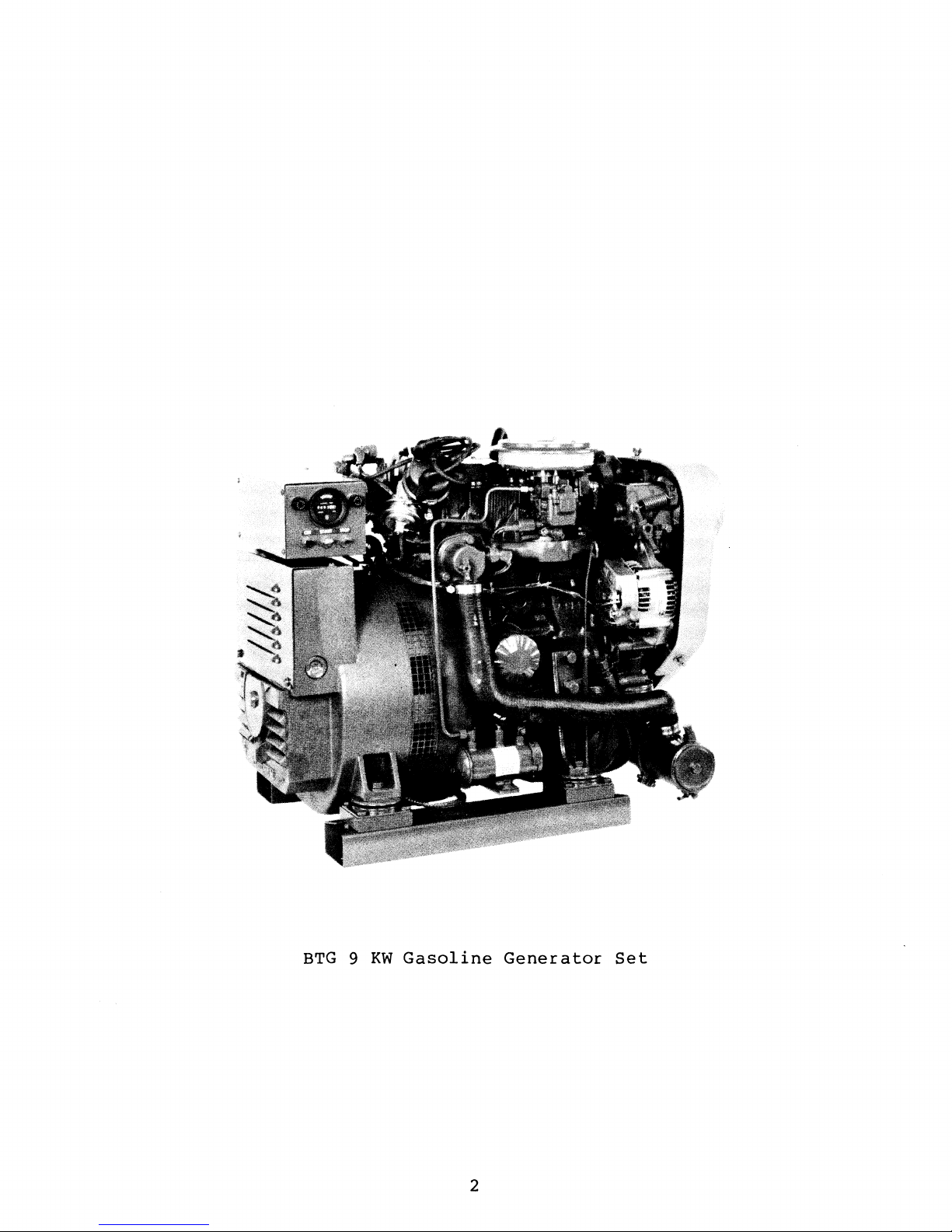
BTG 9 KW
Gasoline
Generator
2
Set
Page 9

GENERAL
MARINE
SPECIFICATIONS
BTG 9 KW
GASOLINE
GENERATOR
SET
Engine
Type
Combustion
Valve
Bor
Piston
Firing
Mechanism
e &
Stroke
Displacement
Order
Direction
Compression
Compression
Valve
Timing
Chamber
of
Rotation
Ratio
Pressure
Gasoline,
in-line
Multi-sphere
Overhead
2.99
60.6
x
2.87
cubic
1-2-3
Clockwise,
9.5:1
177.8
Intake
Intake
Exhaust
Exhaust
psi
Opens
Closes
Opens
Closes
4-cycle,
type
camshaft,
inches
inches
when
(12.5
19·
51·
51·
19·
3-cylinder,
belt-driven
(76 X 73
(0.993
viewed
kg/cm2),
BTDC
ABDC
BBDC
ATDC
liter)
from
at
mm)
the
350
vertical,
front
rpm
Valve
Valve
(eng
Eng
Seat
Clearance
ine
ine
Speed
Dimensions
Weight
Sea
Water
(measured
from
Fuel
heat
Consumption
Angle
warm)
Flow,
at
discharge
exchanger)
at
1800
rpm
Intake
Exhaust
Intake
Exhaust
1800
rpm
governor)
Height:
Width:
Length:
386
lb
4.5
-
1.5
gph
output
45·
45·
0.0079
0.0079
(belt-driven
23.38
18.69
28.25
(175.0
5.0
(5.68
kg)
gpm
lph)
(approximate)
inch
inch
inches
inches
inches
(17.03
(0.20
(0.20
mechanical
(593.85
(474.73
(717.55
-
18.92
at
full
mm)
rom)
rom)
rom)
mm)
lpm)
rated
3
Page 10

SYSTEMS
SPECIFICATIONS
FUEL
SYSTEM
Fuel
Carburetor
Governor
Lift
Air
pump
Cleaner
COOLING
General
Operating
Fresh
Water
SYSTEM
temperature
Pump
Unleaded
(minimum
Down-draft,
Mechanical
12-Volt
lift
Metal
Fresh
or
leaded
octane
single-barrel
type,
electric;
capacity
screen
water-cooled
6
type
89)
ft
gasoline
belt-driven
-
block,
thermostatically-controlled
with
130-lS0·F
Centrifugal
impeller,
sea
water
(55·
exchanger
-
type,
belt-driven
66·C)
metal
(1.8
m)
cleanable
system
Sea
Water
Sea
Water
(measured
Pump
Flow,
at
exchanger)
System
(fresh
Capacity
water)
LUBRICATION
General
Oil
Filter
Sump
(filter
Oil
(engine
Capacity
not
Pressure,
hot)
at
discharge
SYSTEM
included)
at
1800
1800
rpm
from
rpm
heat
positive
impeller,
4.75
5.7
-
qts
5.0
Pressure
chain-driven
Full
flow,
type.
3.0
qts
50 -70
(2.841
psi
displacement
belt-driven
gpm
(5.39
type
(17.98
liters)
with
through
paper
liters)
(3.5
-
rubber
-
trochoid
balance
element,
4.9
18.92
spin-on
kg/cm
Ipm)
pump,
shafts
2
)
Oil
Grade
API
4
spec
SD
or
SE
Page 11
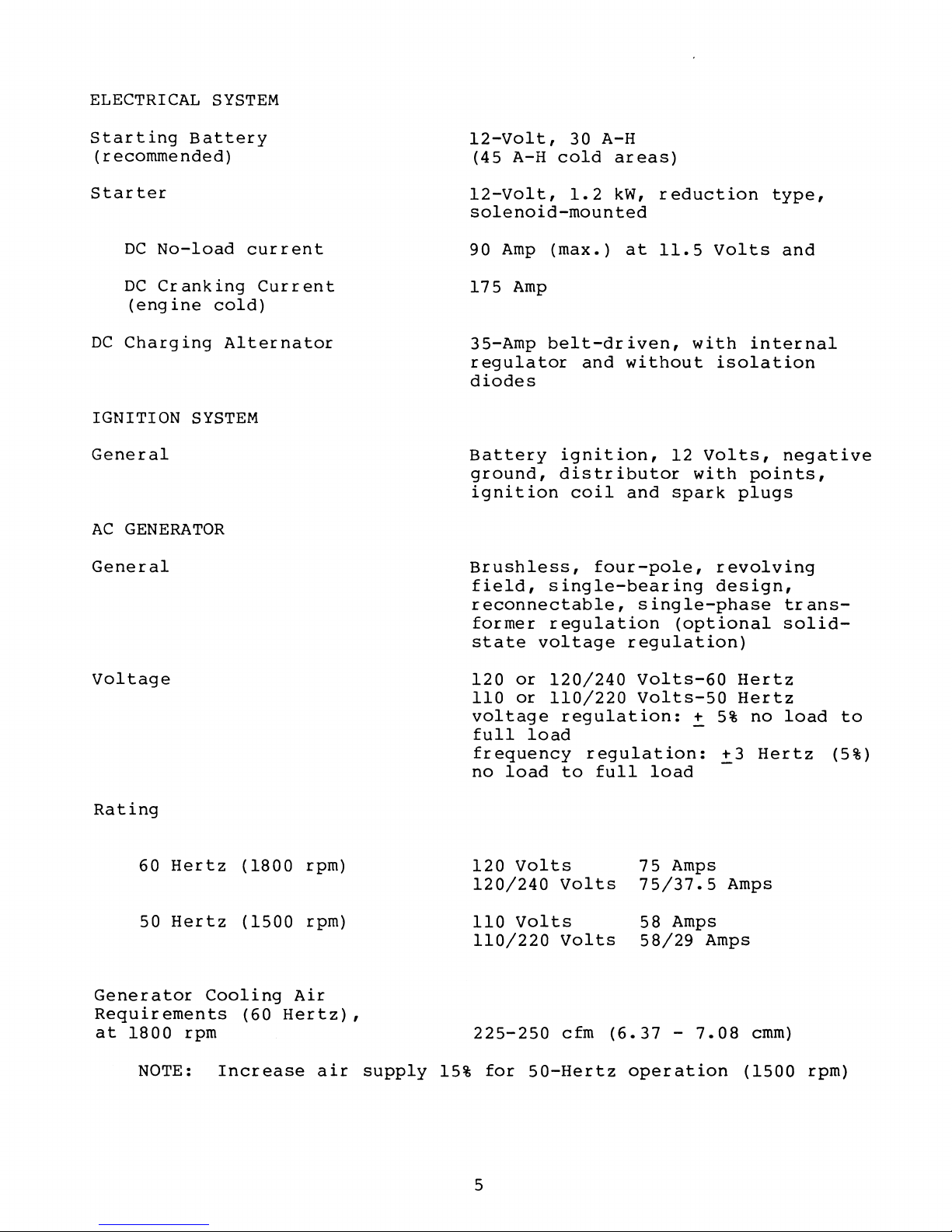
ELECTRICAL
SYSTEM
Starting
Battery
(recommended)
Starter
DC
No-load
DC
Cranking
(eng
ine
DC
Charging
IGNITION
SYSTEM
General
AC
GENERATOR
General
current
Current
cold)
Alternator
l2-Volt,
(45
A-H
l2-Volt,
30
cold
1.2
A-H
solenoid-mounted
90
Amp
175
35-Amp
regulator
(max.)
Amp
belt-driven,
and
diodes
Battery
ground,
ignition
Brushless,
field,
ignition,
distributor
coil
four-pole,
single-bearing
reconnectable,
former
state
regulation
voltage
areas)
kW,
reduction
at
11.5
without
12
and
spark
single-phase
(optional
regulation)
Volts
with
isolation
Volts,
with
revolving
design,
type,
and
internal
negative
points,
plugs
trans-
solid-
Voltage
Rating
60
Hertz
50
Hertz
Generator
Requirements
at
1800
rpm
NOTE:
(1800
(1500
Cooling
(60
Increase
rpm)
rpm)
Air
Hertz),
air
supply
120
110
voltage
full
frequency
no
120
120/240
110
110/220
225-250
15%
load
for
or
120/240
or
110/220
regulation:
load
to
Volts
Volts
Volts
Volts
cfm
50-Hertz
Volts-60
Volts-50
regulation:
full
load
75
75/37.5
58
58/29
(6.37
operation
+
-
Amps
Amps
Amps
-
7.08
Hertz
Hertz
5%
+3
Amps
no
Hertz
cmm)
(1500
load
rpm)
to
(5%)
5
Page 12

Engine
Requirements,
at
Combustion
1800
rpm
(60
Air
Hertz),
32
cfm
(0.906
cmm)
TUNE-UP
Spark P lug
Contact
Dwell
Condenser
Valve
(warm
Timing,
SPECIFICATIONS
Point
Angle
Clearance
eng
at
Gap
Clearance
Capacity
ine)
1800
rpm
0.028
0.016
58'
-
0.27
Intake
Exhaust
14
•
+
-
.036
-
.020
-
66'
microfarad
0.0079
0.0079
l'
BTDC
inch
inch
inch
inch
(0.7
(0.4
(0.20
(0.20
rom)
0.9
-
mm)
0.5
-
rom)
mm)
6
Page 13

General
INSTALLATION
Proper
are
of
Factor
for
exhaust
exhaust
and
electrical
Factors
and
cussed
location
prime
s
the
access
in
importance.
in
the
generator
system
and
in
expel
the
for
this
and
installation
installation
for
to
properly
exhaust
connections.
location
serv
icing
manual.
proper
gas;
that
and
of
that
must
cooling
discharge
cooling
must
repair
the
be
raw
be
considered
s.
generator
considered
and
engine
cooling
water
These
set
water,
supply;
are
factor
in
the
are
ventilation
combustion
quiet
fuel
proper
s
will
vessel
air;
supply;
support
be
dis-
the
There
properly
Location
The
location
areas,
It
should
and
repairs.
as
well.
fresh
Hot
The
to
generator
platform
support
fastened
are
four
secure
and
be
cooling
to
away
properly
The
on
the
it
1/2-inch
the
generator
should
from
Access
location
air
for
discharge
which
generator
at
all
bolt
be
being
ventilated
for
the
the
angles
holes
such
splashed
major
must
generator
air
must
generator
and
of
to
that
be
vessel
(1/2"
in
its
it
by
and
repairs
properly
be
is
securely
7
Mounting
each
mounting
is
..9!..,y,
bilge
accessible
should
end
and
removed
mounted
operation.
Holes)
generator
platform.
above
water
or
be
ventilated
for
from
should
hold
the
water
for
given
engine
the
mounting
low-lying
from
minor
consideration
to
provide
combustion.
generator
be
strong
mounting
rail
vapor
above.
servicing
the
area.
enough
rails
to
Page 14
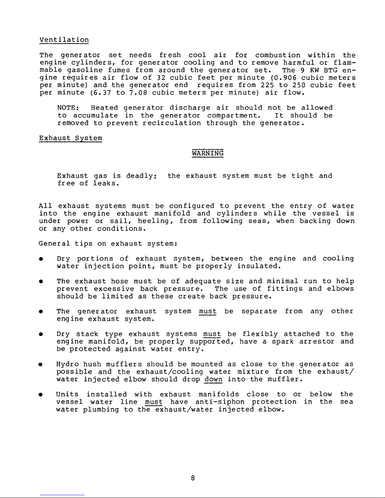
ventilation
The
engine
mable
gine
per
per
Exhaust
All
into
under
or
generator
requires
minute)
minute
NOTE:
to
removed
Exhaust
free
exhaust
any
cylinders,
gasoline
accumulate
System
of
the
engine
power
other
set
fumes
air
and
the
(6.37
Heated
to
gas
leaks.
systems
or
conditions.
to
prevent
is
exhaust
sail,
needs
for
generator
from
flow
generator
of
generator
7.08
in
the
recirculation
deadlY1
must
heeling,
fresh
around
32
cubic
end
cubic
discharge
generator
the
be
configured
manifold
cool
cooling
the
feet
requires
meters
WARNING
exhaust
and
from
air
generator
per
air
compartment.
through
following
for
and
to
per
minute
from
minute)
should
system
to
prevent
cylinders
combustion
remove
set.
225
air
the
generator.
must
while
seas,
The
(0.906
to
not
It
be
the
when
harmful
9
cubic
250
flow.
be
allowed
should
tight
entry
the
backing
within
or
KW
BTG
cubic
be
and
of
vessel
the
flam-
en-
meters
feet
water
is
down
General
•
Dry
water
•
The
prevent
should
•
The
engine
•
Dry
engine
be
•
Hydro
possible
water
units
•
vessel
water
tips
portions
exhaust
gener
stack
protected
on
injection
excessive
be
exhaust
manifold,
hush
injected
installed
water
plumbing
exhaust
hose
limited
ator
type
against
mufflers
and
system:
of
exhaust
point,
must
back
as
exhaust
system.
exhaust
be
should
the
exhaust/cooling
elbow
with
line
to
must
the
system,
must
be
pressure.
these
properly
water
should
exhaust
exhaust/water
be
of
adequate
create
system
systems
entry.
be
drop
have
between
properly
The
back
~
~
supported,
mounted
water
down
manifolds
anti-siphon
injected
insulated.
size
use
pressure.
be
separate
be
flexibly
have
as
close
mixture
into
the
and
close
engine
minimal
of
fittings
a
spark
to
the
muffler.
protection
elbow.
from
attached
the
from
to
and
run
and
any
arrestor
generator
the
or
below
in
cooling
to
help
elbows
other
to
the
and
exhaust/
the
the
sea
as
8
Page 15
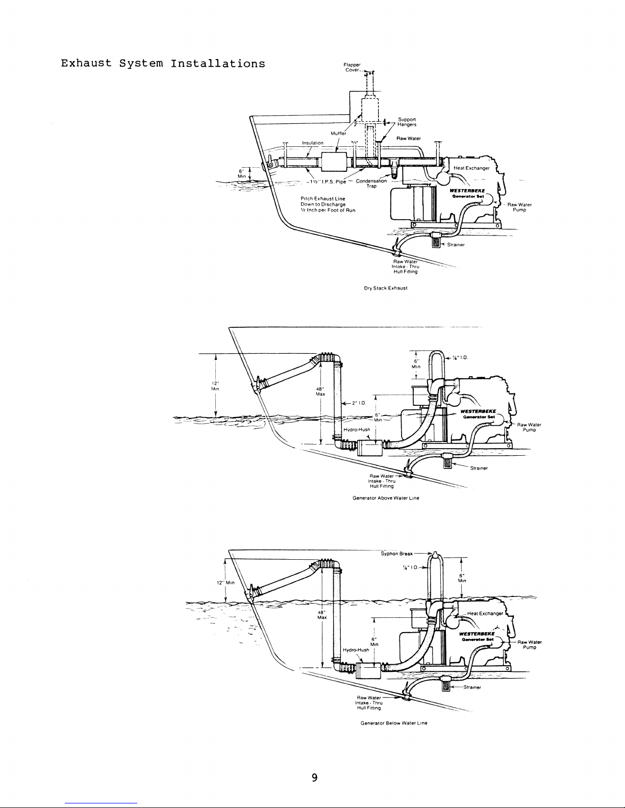
Exhaust
System
Installations
Flapper
Cover_~.f
'1
! I
Dry
Slack
SUPpor1
Hangers
Exhaust
-
RawWaler
Pump
Generator Above Water
Lme
AawWater
Pump
AawWater
Pump
9
Generator
Below
Water
Lme
Page 16

CAUTION
Overcranking
amounts
Exhaust
discharge
cranking.
and
starting
Fuel
System
Gasoline
potential
promptly
The
tank
fuel
and
Anti-Siphon
siphoning
tank
a
when
fitting
connection
designed
then
supply
not
action
there
loosens
and
and
with
of
cooling
gas
pressure
accumulated
Shut
open
and
correct.
leakage
cause
and
ensure
to
teed
off
Protection
that
is
to
the
installed
no
off
thru-hull
once
started.
in
of
the
generator
the
is
permits
a
break
create
connection
to
engine
water
may
water
or
around
fire
the
compartment
supply
the
or
a
protect
pumped
not
during
water
Investigate
WARNING
the
and/or
should
to
term
fuel
applied
to
rupture
leak
to
the
against
start
in
always
generator
explosion.
be
another
continue
in
in
the
engine.
results
to
periods
supply
is
properly
from
engine.
to
the
fuel
line
fuel
the
exhaust
be
until
reason
compartment
its
the
to
flow
supply
between
Fuel
siphoning.
in
sufficient
of
unit
(s)
Repair
ventilated.
own
means
out
systems
excessive
system.
excessive
starts
for
hard
is
leaks
pickup
of
preventing
of
the
line,
the
fuel
----
to
a
in
or
must
the
fuel
when
tank
be
The
illustrations
publication
layouts
NOTE:
shut-off
line
The
fuel
vibration
inches.
A
filter/water
between
water
and/or
The
that
must
from
engine
fuel
water
not
with
is
line
and
Use
the
tank
Fuel
anti-siphon
Anti-siphon
valves
routed
should
chafing.
as
separator
fuel
the
fuel,
failure.
vent
cannot
be
shown
System
must
below
few
connections
tank
should
enter
allowed
on
Compliance
be
routed
The
is
and
both
be
the
the
following
protection.
devices
be
installed
the
top
and
line
recommended
eng
ine,
of
which
routed,
fuel
to
tank
accumulate
Guideline),
or
level
supported
should
in
the
to
are
and
(s)
page
(taken
show
electrically-operated
when
of
be
supply
for
remove
prime
the
through
the
the
fuel
to
supported
line
use
harmful
causes
discharge
in
fuel
prevent
in
the
the
the
from
basic
distribution
tank.
every
as
possible.
fuel
debr
of
fuel
located,
vent.
vent
Coast
fuel
leaks
12 -14
system,
is
system
so
Moisture
Guard
system
fuel
from
and
that
line.
10
Page 17

Basic
Fuel
[UE
~
T AN
System
FUEL
~
TO
Layouts
LINE
ALWAYS
P--DLE!!",V_E_L_-==....:!!:..=.=!",,"=,_
NO
with
ABOVE
....
ANTI·SIPHON
Anti-Siphon
FUEL
TANK
TOP
LEVEL
_=~~=-====:=.~~:.-:-
DEVICE
OPERATED
VALVE
__
OR
NEEDED
Protection
-::-='::=:-:=:-=-=~~-:-d
ELECTRICALLY
ANTI·SIPHON DEVICE
VALVE
FUEL
TANK
TOP
~
ANTI·SIPHON
STOP
GOES BELOW
ANTI·SIPHON DEVICE
0-,.---- OPERATED
FUEL
liNE
BELOW
OR
ELECTRICALLY
AT
FUEL
TANK
WITHDRAWAL
LEVEL
FUEL
VALVE
DEVICE
AT
FUEL
OR
POINT WHERE
TANK
OR
ELECTRICALLY
FUEL
STOP
VALVE
------;p
FUEL
FUEL
TANK
TOP
OPERATED FUEL STOP
FITTING
LINE
BELOW
TOP
LEVEL
ELECTRICALLY
FUEL
DISTRIBUTION
TOP
LEVEL
TANK
TOP
LEVEL
ANTI·SIPHON
J OPERATED
FUEL
TANK
OPERATED
LEVEL
FUEL
LINE
DEVICE
FUEL
OR ELECTR
STOP
VALVE
--I
ICALL
Y
11
Page 18

Fuel
system
alcohols)
in
the
components
blended
component
must
fuels.--pailure
failure
and
be
compatible
possible
to
ensure
injury
with
oxygenate
compatibility
to
the
user.
(butanes,
will
result
The
pump
use
is
discouraged.
on
debris
ing
pressure
Cooling
The
generator
exchanger.
pumped
the
exhaust
engine
The
and
it
sea
sea
through
ting.
brought
water
the
strainer
pump.
thru-hull
and
be
to
wire-reinforced
collapse
water
tion.
pump
Sea
mounted
so
as
to
of
the
under
System
into
fresh
water
water
This
through
fitting
the
from
water
at
be
check
eng
ine
their
for
engine
Sea
water
the
exchanger
discharge,
water
pump
should
a
flush-type
sea
and
Hoses
sea
the
during
or
below
always
valves
Check
to
seats,
check
valves
is
system.
is
be
water
a
visual-type
then
routed
to
water
suction
generator
strainers
the
self-primed.
in
place
valves
draw
defeating
fresh
is
used
by
carrying
belt-driven
supplied
hull
should
delivered
from
the
strainer
pump,
to
of
should
water
of
may
fuel
will
through
contribute
water-cooled
as
the
a
sea
with
to
fit-
be
sea
to
the
should
prevent
the
sea
opera-
be
line
the
tax
their
exchange
water
it
Longest Span
solenoid-type
the
ability
them.
purpose.
to
by
an
pump
the
Belt Tension
3/8-1/2 Inch
Deflection
and
heat
at
shut-off
of
the
Also,
Too
vapor
lock
engine-mounted
cooling
medium
then
removed
fuel
they
high
shutdowns.
injected
valves
can
a
crack-
and
from
lift
trap
heat
is
into
the
Do
not
hull
supply
fitting
to
pressure
fitting,
underway,
the
sea
water
the
generator
Flush-type,
be
located
angles
The
of
use
plumbing
restrictive
use
the
while
can
boat
of
the
CAUTION
a
scoop-type
for
generator.
against
the
push
pump
impeller
exhaust
clear,
on
the
operation.
common-type
sea
inside
the
this
vessel
water
thru-hull
hull
water
diameter.
thru-
sea
water
Water
and
system,
so
as
street
circuit.
type
is
past
in
to
fittings
to
12
filling
be
below
elbows
These
Machined
it
are
the
is
fittings
and
the
engine
recommended
waterline
not
recommended
generally
are
as
and
during
have
preferred.
well.
should
all
a
very
for
Page 19

Automatic
Shutdown
High
An
open
Exhaust
exhaust
the
perature,
switch
22S·F
High
A
high
stat
the
ture
19S·F
Low
A
low
opens
(107·C).
Water
water
housing
generator
reach
(approximate).
Oil
oil
gallery
maintaining
shut
the
Exhaust
Temperature
temperature
ignition
indicating
at
260
Temperature
temperature
to
sense
should
approximately
Pressure
Shutdown
pressure
and
is
the
closed
electr
generator
Back-Pressure
switch
circuit
a
-
270·F
the
shutdown
down
Shutdown
should
lack
of
(127
Shutdown
switch
fresh
water
engine
20S·
Switch
when
ical
when
eng
run
engine
is
proper
Switch
is
fresh
F
switch
ine
located
(96·C)
circuit.
Switch
the
sea
-
l32·C)
(normally
located
coolant
water
+
-
(normally
is
oil
pressure
oil
(normally
on
the
switch
water
and
in
temperature
coolant
S·.
open)
located
This
pressure
exhaust
sense
coolant
resets
closed)
the
This
reaches
switch
drops
closed)
excessive
at
area
of
operating
switch
in
the
to
elbow
and
flow.
approximately
the
thermo-
and
shut
tempera-
resets
engine
10
-
IS
will
open
10 -IS
will
tem-
This
down
at
oil
psi,
and
psi.
Exhaust
prior
vice.
cessive
back-pressure
to
(Refer
back-pressure
performance
Measure
elbow
back-pressure
with
Back-pressure
over
39
at
1-1/2
3
inches
4·
C},
psi
inches
Excessive
by
small
muffler,
pockets
exhaust
Oil
Drain
An
oil
end
drained
the
or
system.
sump
secured
from
hose
tainer.
pump
added,
putting
to
the
and
generator
generator
(manometer)
of
mercury
of
water
22
ounces
(967
kg/m2).
back-pressure
diameter
sharp
high
bends,
volume
drain
by
a
this
from
The
the
hose
for
should
a
generator
illustration.)
will
power
at
under
(0.104
column
per
square
can
exhaust
fittings,
of
hose
is
bracket
hose
by
suppor t br
cap
fitting
easier
be
into
affect
output.
the
full
should
kg/cm2),
(0.099)
be
hose,
water
installed
at
the
removing
acket
is
checked
ser-
Ex-
engine
exhaust
load.
not
kg/cm
inch
caused
small
water
in
the
on
front
the
and
1/4-NPT
removal
be
2
or
the
of
cap
lower
engine
the
and
ing
and
of
engine.
the
the
can
oil,
Mercury
Manometer
with
the
discharge
hose
be
extended,
if
/,Exhaust
\
discharge
Oil
in
to
desired.
Exhaust
Elbow
may
end
a
con-
or
be
of
a
13
Page 20

DC
Electrical
Connections
A common
generator,
stud.
Connect
for
this
To
failure,
engine
Grounding
The
Guard
connected
engine
prevents
and
Optional
tor
generator
regulation
smaller
must
ground
next
It
is
recommended
battery
connection.
avoid
do
is
between
grounded
accidental
electrical
be
the
Remote
for
to
positive
an
overcharg
not
running.
set
must
33CFR-183
the
starter
same
Start/Stop
negative
the
starter,
that
(+)
ing
disconnect
be
grounded
generator
motor
passage
conductors
size
as
(-)
the
to
CAUTION
which
circuit.
of
the
Panel
DC
is
in
the
battery
the
condition,
the
DC
to
specifies
set
cranking
largest
and
and
common
Instrument
found
form
starter
battery
comply
the
This
current
to
battery
at
of
ground
solenoid
and
poss
with
that
vessel's
conductor
the
the
bellhousing
a
threaded
be
connected
ible
source
United
a common
through
engines.
cable.
Panel
terminal
equipment
while
States
conductor
main
(common
propulsion
fuel
This
of
the
grounding
here.
tagged
the
Coast
be
ground)
systems
conduc-
An
optional
switches
will
is
engine
connected
panel.
start/stop
galley.
An
an
engine
can
panel
tored
*
sizes
glow
depressed
optional
engine
be
and
and
35698
for
remote
and
starts
(Refer
operating
wired
and * 36397
a
when
to
(a
to
the
panel
instrument
oil
pressure
to
mounted
the
switches
specific
the
start/stop
green
ON
engage
signal
terminal
to
wir
can
hourmeter
the
terminal
at
for
wire
be
the
RUN
indicator
switch
the
to
ing
diagrams
mounted
panel
gauge,
and
location
operated.
proper
lengths.)
panel
is
starter,
release
blocks
is
water
start/stop
blocks
connection
is
available,
light.
depressed,
and
the
START
in
the
*
35706
in
areas
available
temperature
in
where
(Refer
on
This
dim
then
generator-mounted
and * 36397.)
such
control
the
the
to
poin
when
glow
switch).
as
which
gauge,
switches.
generator-mounted
instruments
the
DC
ts
and
which
RUN
indicator
the
br
ight
This
the
wheel
is
supplied
DC
wir
ing
recommended
are
START
when
panel
This
house
voltmeter,
This
can
be
schematics
mounted
light
switch
the
is
control
remote
or
with
panel
control
moni-
wir
e
14
Page 21

I-'
\J1
OPTIONAL
R,MOn
STAhT
PANIL(RtJ\R
VI'W)
PN
33703
,-
--
-----
- - -
---
---
--
----
-----------1
I
I
I
I
I
I
I
I
I
I
I
I
I
I
I
I w
I 0..
I
0:
l-
V>
0:
::l
0..
i
D
W
0:
L_
MINIMLJ~1
WIBE
GALJCES
[)
,~
STOP
'>TAR!
'IlRtU/W/PUf,
snllP,
""IG
lit.O
~
[il
-\
tilfHO
IN/PIJH
"TR
IPC
<r
~
n.
~
k.W
Be
?I'·'
,
a
l£
,.J
I-
G.SKWBC
119K~.JBT
<;1::1:.
D~,'G.354Y:lH.SEE
l.A/C
36397
0:
'"
.1
'12
HL!wlR,O
-
16
PURPL
I:
STRIPE
;1
1
.~
"'2
R£O/W/PUf,ru
...
TO
T2·1
,
19A/-IP STARTiNG
T4-1
I
6 AMP
RUNNING
I
1
0
T4
_
2
I
l-----.:J..±J:~npLt:__________..
TO
T2-2
:
£'
AMP
I
I
0
~
I
I
T4-3
,
I
I
I
IQ
G
I
14-4
I
,
,
I
€}-
___
~~~BLACK
__
•
TO
T2-5
T~-5
I 2
AMP
I
,
,
I
-----------------------~
121\t-If'
STARTI'!!>
Rl2
,(El/\
...
JI~F.r
~ThlPl
..
TO
1 I 2
l~
AMP
!::>TA.RTIt~G
L.------.:
b
ANP
rtUt<.,
~I
~;;G:------------------;;·c-J=
2HrH'-;J7T.\"J/npC-;U"'''-;SC;T'''k-;'I-;-E~''
TO
T
1-1
Ii
TO
T B I 2
II
TOTB32
II
TO
TH
3 5
TO
TB3
3
TO
TBI
I
WIRE
LENGTH
FROrol
GENERATOR TO
PANEUFTI
WIRE
r=)~~
~~~~0~()'o~~-I{~~~{t~'-~40t-~/iI50-~6S
-
GAUGE
---
--
----
----
----------
IAWGI
14
12
12
10
10
9 8
,""
..
mulw
E
SfEPBEI(.
E CCrlF'OPATICJN
~:~'.~'.~'=
---A-VQ!L-~!:!lA;,""Ot:···
JU
-
,''-- NTS -:;:;;;:;;..-;;-;;------
___
________
__
.L
.........
'"''
WIRING
DIAG
R<MOTE START
~_
h·~:~'~J~~~-:~-l~~~O
6
IL--
__
_
::0
CD
8
rt
CD
rn
rt
IlJ
1"1
rt
'i:I
IlJ
;J
CD
I-'
::E;
.....
1"1
.....
;J
lO
o
.....
IlJ
lO
1"1
IlJ
S
::tI=
W
VI
-...J
o
0'1
Page 22

I-'
m
!!.!!ill:!&.
~
r-·~-,§'\
-IOvIiN
~
BATTERY
~~
T~~,~.
bIlTO~ItD
;t·.,
..
BlOO'
I
)1/
STARTER
~
.-
f.I'KU,T
b~[A"ER
,-----~
G;'ttn-o
,
I"NIT,ON
COIL
·'.Pvll./"'HT
~TII.
j[:~
~~~~,
<
fr(~-,·-j
, :
Ol~
PAt:.,S I
')
:.-
:."l1,Tl-llilUTOR
~
~[.!.j~E~
__
J
4----,
i
*'\T-EA~
OPTIONI\L
BALLAST
RESI!:>TOQ
I TEMP I
ir'Of:j
OPTIONAL
"141'l'1I
r
~f1
,.
(Hlll<E;(l,\f,.flJ
"'L~_JJ
,.
~lJL[N<JlO
(,
&.hH)
'rE.
~,J
t L
; .
'U'"
~~~~'Hl~S
il
~:
~
I I 1
.....
~~,
"."
--+t-+-~-I-~~-"
~~~~~ST 1 ~--_---,
~
LI+--+_
fOR
(J)"N(CTlON!>
TO
"'040T[
~r"'lIr
..... U
A(MOl( , ..
!>TIlUHlNr
P'II'Iu.!>,'j,1:t
UII-.moG"
}!iIOto ~ .¥.I,,'J8
·'4P,,1I.
T8-3
TB-2
""1"
~
• ....
61.
"'';'(lllltDSII-,P,
·,,,p"i;
~
"~
IItU/~u~
~'~,P!
r+-
r--
..
E~J
:ll)
I~
l,Ci]
HI,",OVE
THI';,
JIJMl-'lR
'WHE'"
II
.
"-
il~~'~'
L-_-"'..::"":~'''';~'''''"-''''''''"'"'-'
+-HI---+------~-+~.Lr)l
I 2 1 B I
.'4
R(OI~'1,J1<
'.T~I~1
.
_-'
'"",,
~:ttJ
?~,"':,~';'lU
~~
~_j
11
~_
.
L
·'4~,
[)
~ll~DC
:n''''.11
~w
:(:(8
. :
~t!!=:MA!l£
[)t"t>RA~
_________
~l~~;
~~{-.--------
t '
----'Cf)';{--·-----~
""I~/'
"
! ,
flU,,"
t .... ,
....
I"."I-;;::::;:;C;o TI''''''"'
.... L ......
'
~
N·
;;;
.-1;:;-""1
"'
......
,.ri
't':
:.'"~
:
";
'"V-I\" --..
-I----.bP.
,",v---":\:
----.0.)1
r
x.
____
_
@--@
+·-e'~"~
':>TOl>
!oW.
FU",-[
l
15A
S8
HC.U~Ml1ER
STMH
SW
ru';o[
I
"
UU
SWITCH
~i
-]
"~!J:~~.
--~-
-0;:~-
tot.UA;T
II(!.I!.TOJI
1 S
COOL
~ ~1~l~I~L~!~
~"~l4':~l
:~'-"'"-
12
~~-:v~:;--·-i
0-
t-~:=-=
, I
~RII
• I
Pl.ur.~
lfJ-
r
t-··
-~--L
__
J
TI"'i~
-""-
'<~E:-----
fI:!l~l!.""
';:H-----
I.
WESHkuEKE"
GASULINE MARINE
GENEH.ATUR~
AS SHIPf.'ELJ
HUlM
HIE
FA(;TUky
AND
!:xClUStvE
OF
OPTIONAL
Ht-MOlt
IN~TRlJMEIH
(JH
ClJNTHOI
PANELS
l)JMI'lY
WITH us. COAST
GUARD
..
B(;F1-I183,
ACl:ES::iOHY
INSTkUMI:::Nl
ANO
WNTROl
PANHS
DvNUT
NECESSAlmy
SO
COMPLY
AND
"'~E
INHNOtD
TO
BE
INSTALLED
A~OVE
DECto;
ANO'lsm
AHD
FROM
GA::.OllN[
SuuRCES"IN
ACCuHuANCE
WITH
33CfR
183.41014
IT IS THE
I~ESPUNSlbILiTY
Uf
THE BOAT
MANUFACTuHl:n
TO
ItlSUH[
THAT
THE
INSTALLATION
Of
TIU:.~E
GENrf(ATOr~S,ANO
OPTIONAIl.Y,
TliEIU
REMOTI:. INSTHUMl:.NT
lit;
CONTROL
PANEl.S
CQMPL Y
WITH
3.KFH
HB.
c..THIS PROOUCT IS PH.Un.CTEU
BY
A MANUAL
H[StT
Clr~ClIIT
BlUAKlR
lOCATED
Nt:AH
HIE
SlARTER
ANO
AS
ClOSE.
,),~
PQS-::'IBI E
TO
TItl
SUUHCt
OF
CURr~lNT.
[){C[~SIVE
CuRk£fH
URAIN
ArlYWIiER[
IN
THE
INSrHlJ~llNT
PilNEL
,WI~ING
OR
cN&INl
Will
CAU::.E
THE
B~lAKEH
TO
11~1P.
INTHIS
lV[NT
Ttit. I:.N(,INE
WilL
StlLJT
LoOWN
BECAUSE THE
OPENI:.U
8RlAKEH
Will
j)lScONtH:CI
THI:.
fUE.l
SUPPL.Y.
lHl:REFUHE
THE
BUILDfR
laWNER
MUST
BE
SURE
IHAl
fin.
INSTHU"",ENT
t'ANEL
,WIRING
ANU ENGtNE
ARE
INsrALU:D
TO
PRt.VI:.NT
CuNTACl
BrTwUN
£1
FCIHICAl
UEvlCES
AND
SALT
WATER.
3.AN
ON
Off
SWITCH
MUST
BE
IWiTAl1
t:D
TO UISC;ONNI (;1
HIE
STARIEH
FROM
THE
I:JATT£RY
IN
AN
fMEH(.[NCY
ANU WHEN
HAVIN(3
ltit
&OAT.
TWHVI:
VOLT STARTI:.HS
TYl-llCAllY
UfoIAW
~OO
TO
j(){J
At-IFJS
WHEN
CflMIKIN(.,. 1 liE
DUI-lA1IOt4
Of
INDI
....
IUUAL
CRANt(INll
{.;Y(,LES
SHOUlD
NOT
EXCI:.E:D
jO
~rCONDS. A ~WlrCIi
WITtI
A C(,NTiNUlJS
kATIN
...
OF
I7~AMP~
AT
12VULTS
Wilt
NOIIMALLY
~U-/
....
E:.
1HtS
HJNClIUN,BIJT
A
~WITCH
MUST
NOT
~E
USED
TO
'MAI\E" THE
CIHCUIT.
4.SENDER::i
AHE
SUPl'lIE:.O WITH
OPliONAl
INSTIHJME:NT
j'ANH.
[
~1
..
~P.\\'·~"!l"l'''~
__
..
__
INTS
"~WIR'NG
O,.GJ:::k:;,J.
---_ ..
~~J~~1Jif..
Ci<J!iRill
________________
u_~___
IO.~~
36397
g
~
.....
M
.....
::s
U)
0
.....
III
I.C
M
~
=tI=
W
m
W
\0
-....J
Page 23

......
-...J
9KW
BT
SEE
DWG.36397
TO
T81-
2
TO
TB3-2
TO
T82-1
TO
T82-2
TO
T83-S
TO
T81-1
TO
T63-3
'r
It P[I(>i 0
9KW
fe"oIl"'loIAL _ .Jl}
,.. ,
PI
()PClAie-
'>
GAGe
t..JIllill!oIC,
..lJ
REMOTE
INSTRUI'IENT
PANEL
(REAR
VIE,,j)
ASS'Y
PN
33/02
r
--
- -
--
-
-----
---
- - -
--
- -
-----------
-------------1
I
I
I
I
I
I
I
I
I
4KW
BC
I
REo/W/PURPLf
STRIPE
r--
In.
~
STOP
r-$
~
ot-
L---
START
~
~2REo
I
Lj"1/w/PUR
ON
STRIPE
"12 Yi:L
'wi
n
EoSTRIPE
6.!)KW
BC
I
.12REo/W/PURPLE
SEE
0\'/6.
3!)<;39 STRIPE
. 'tZREO/W/PUR
T4-1
'12REO/w/pUR
"mlPe
I
TO
T2-1 19AMP
STAR
6 AMP
RUN
"16
PURPLE
OIL
PRtSSuRE
~
-16
Bl
ACK
'16
PURPL
E
~
I
"14PURPLE
T4-2
il6PURPLE
---f.----+--+----1
TO
T2-2
2AMP
'16
BL
ACK
,----
I
~16LT.BLUE
I
"14LT.&LUE
T4)/
TO
T2-3
~
'"
u
«
--'
II' T4-4 I
~I
TOT2-4.
I
14
TAN
EIEI
.'16TAN
TO
T2-5'
:
"14BLACK
I
s
T4-
e
,t/
"16BLACK
I 2AMP
I
I
TO
TI-I'
:'12 puR/wiRED 19AMP STARTING
STRIPE 6
AMP
RUNNING
TO
T1-2.
1"12
vEL/wiRED
12
AMP STARTiNG
STRIPE
I
H
&
T3-2
~
8
D·I
~
I~
--'
IL---..J
HOURS
"IG
PURPLE
r 0
-~
.~
VOLTS
+
w
--'
a.
<r
::>
a.
<D
.-
L
__
_
---
-.---
----
-
--------------------
-
___ ------
___
--1
WESTERElEKE
CORPORATION
MINIMUM
WIRE
GAUGES
- -
WIRE
LENGTH
FROM
GENERATOR
TO
PANEL
(FTl
AVON
MA
02322
A.-
~~~~E
':!"
"t
:~~'~i;l}fi:
"i"
35698
(AWGI
~
(D
5
rt
(D
H
::;l
Ul
rt
1"'1
C
:3
(D
::;l
rt
to
III
::;l
(D
......
~
.....
1"'1
.....
::;l
I.C
t:1
.....
III
I.C
1"'1
~
=It:
W
l.n
0'1
\0
(Xl
Page 24
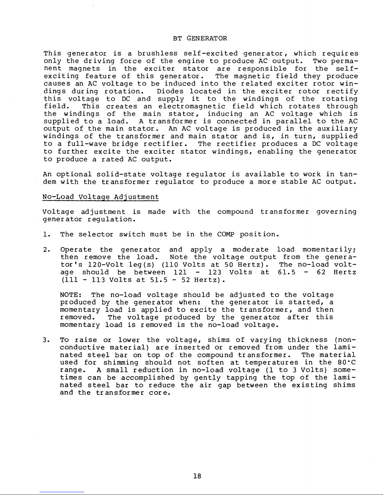
BT
GENERATOR
This
only
nent
generator
the
magnets
exciting
causes
dings
this
voltage
field.
the
windings
supplied
output
windings
to
a
full-wave
to
further
to
produce
An
optional
dem
with
No-Load
Voltage
generator
1.
The
driving
feature
an
AC
during
This
to
of
the
of
excite
a
the
Voltage
adjustment
regulation.
selector
is
a
force
in
the
of
voltage
rotation.
to
DC
creates
of
the
a
load.
main
the
transformer
bridge
the
rated
AC
solid-state
transformer
Adjustment
switch
brushless
of
exciter
this
to
and
an
main
A
stator.
rectifier.
exciter
output.
is
self-excited
the
engine
stator
generator.
be
induced
Diodes
supply
electromagnetic
stator,
transformer
An
AC
and
stator
voltage
regulator
regulator
made
must
with
be
in
into
located
it
is
voltage
main
The
to
the
the
to
produce
are
The
the
in
to
the
field
inducing
connected
is
stator
rectifier
windings,
is
produce
compound
COMP
generator,
AC
responsible
magnetic
related
the
exciter
windings
which
an
in
produced
and
is,
produces
enabling
available
a
more
tr
position.
output.
field
exciter
of
rotates
AC
voltage
parallel
in
in
to
stable
ansformer
which
for
they
rotor
the
the
turn,
a
the
work
requires
Two
perma-
the
self-
produce
rotor
rectify
rotating
through
which
to
the
auxiliary
supplied
DC
voltage
generator
in
AC
output.
governing
win-
is
AC
tan-
2.
NOTE:
momentary
momentary
3.
To
conductive
nated
range.
nated
and
Operate
then
tor's
age
(Ill
remove
120-Volt
should
-
produced
removed.
raise
steel
used
times
for
can
steel
the
the
generator
the
be
113
Volts
The
no-load
by
the
load
The
load
or
lower
material)
bar
shimming
A
small
be
accomplished
bar
transformer
load.
leg
(s)
between
at
voltage
generator
is
applied
voltage
is
removed
the
on
top
should
reduction
to
reduce
core.
(110
51.5
are
and
apply
Note
Volts
121
-
52
should
when:
to
excite
produced
is
the
voltage,
inserted
of
the
not
in
by
the
the
voltage
at
123
Hertz).
be
the
by
no-load
shims
or
compound
soften
no-load
gently
air
gap
a
moderate
50
Hertz).
Volts
adjusted
generator
the
transformer,
the
generator
of
removed
transformer.
at
voltage
tapping
between
load
output
The
at
61.5
to
is
voltage.
varying
from
temperatures
(1
to
the
top
the
momentarily;
from
no-load
the
voltage
started,
and
after
thickness
under
The
in
3
Volts)
of
existing
the
62
then
this
the
the
genera-
volt-
Hertz
a
(non-
lami-
material
the
80·C
somelamishims
18
Page 25

Greer,
'fl.....
N~
2 A
Blue
Terminal
1201240V
YelloV'.
o
a=n
0 7 9
60
80
~
3 0
100
L·
BloCK
COf"\nections
60hz
Blacio\
o-L,
Blue
I Selector
~
~
VOltage AaJustmen:
+--+---Transtormer
Compound
Under
age
and
forces
operation
output.
4.
To
bolts
transformer.
load
lower
Illustration shows terminals
connected for
60
transformer regulation
no
by
the
created
remove
from
voltage
the
Hertz on compound
120/240
circumstances
increasing
transformer
within
may
the
close
laminated
the
compound
The
and,
no-load
volt
attempt
the
gap
core
the
steel
addition
conversely,
voltage.
CAUTION
to
between
without
the
air
transformer
gap
bar,
transformer
of
shim
the
Opllonal
Voltage
Regulator
Blue
& White ' I
Wh
G &
reen
Yellow & White ~ C-Black
increase
the
the
use
and
reduce
remove
and
thickness
removal
t
Regulator
Plug
'C":'-Blue
- "
..
,1
Ite
/ Yellow & Black
~
~~
- I Red & White
the
no-load
laminated
of
shims.
dur
ing
no-load
the
lift
two
the
will
of
shim
& White
& White
steel
Magnetic
generator
voltage
upper
bar
raise
thickness
volt-
bar
securing
from
the
the
no-
will
Varying
load
shim
voltage
thickness
by
4
by
.001
to 6 Volts.
inch
19
(0.025
mm)
will
change
the
no-
Page 26
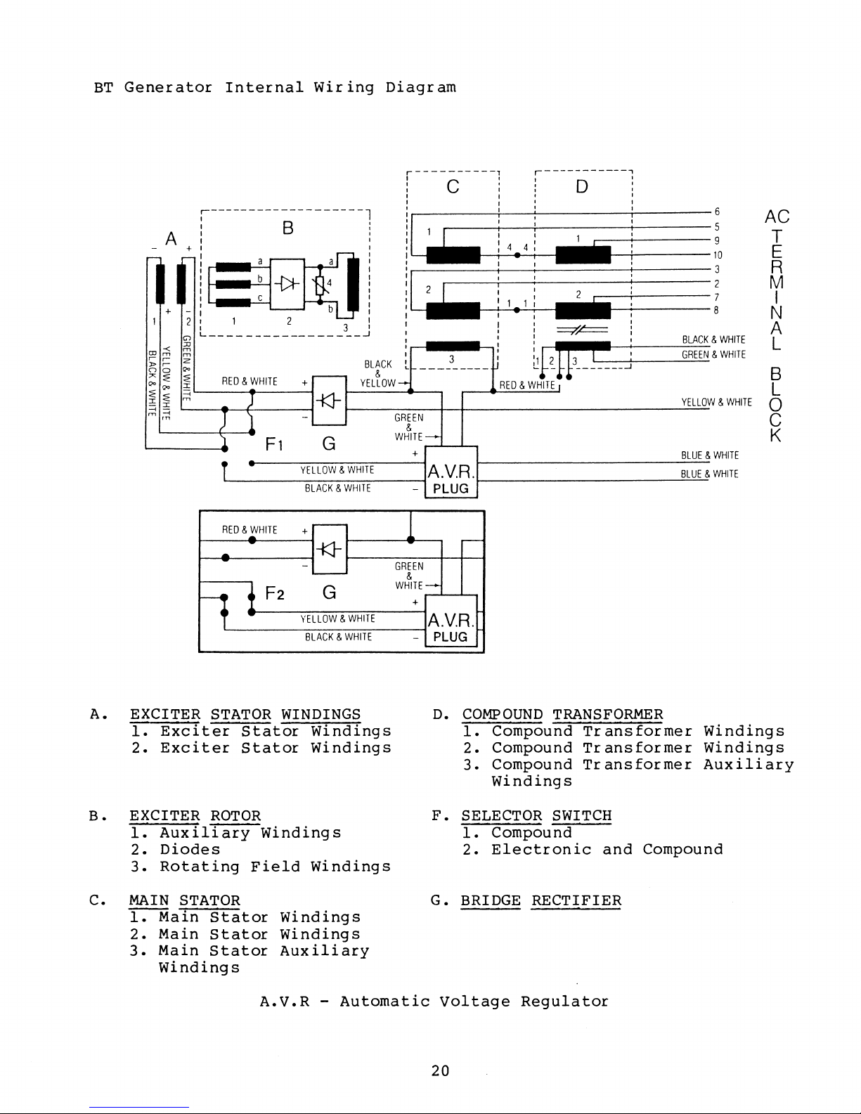
BT
Generator
Internal
Wiring
Diagram
A
+
1-
1
-
+
1
2
~
:JJ
m
m
"';;;
, ,
;z
:»,
Qo
00
~
""~
QoQo
I
::::;
~~
m
~I
--<
-
m--<
'"
,-------------------1
B !
_a
-{)t-
a
4
1==:
-
1
L
_________________
RED & WHITE
)
-
)
'1
1
t
RED & !HITE
...
!
1
F1
F2
b
2
+r--
-
'---
*
3 I
G
YELLOW & WHITE
BLACK & WHITE
+-
-
-
*
G
YELLOW & WHITE
BLACK & WHITE
yELLOW
I
I
I
I
I
I
I
I
I
I
I
I
J
BLACK
&
r----------,
: C I : 0 :
I
I "
I I I 6
I
l~
I
I
I
I
I
I
L
.....
GREEN
&
WHITE-
3 I
_________
+
A.V.R.
-
PLUG
1
GREEN
&
WHITE-
+
~
r-----------,
I'
I
I
i
11
i
I • I
I
I
I
I
I
0
RED & WHITE
...
I
I
=TF=
I
~f~
tI3--L---J
I
.
i
I
I
I
I
I
BLACK
GREEN
YELLO
BLUE
BLUE
A.V.R.
-
PLUG
&
WHITE
&
WHITE
W &
WHITE
&
WHITE
&
WHITE
AC
T
E
R
M
I
N
A
L
B
L
o
C
K
A.
EXCITER STATOR WINDINGS
1.
B.
C.
Exciter
2.
Exciter
EXCITER
1.
Auxiliary
2.
Diodes
3.
Rotating
MAIN
1.
2.
3.
STATOR
Main
Main
Main
Stator
Stator
ROTOR
Field
Stator
Stator
Stator
Windings
Windings
Windings
Auxiliary
Windings
A.V.R
Windings
Windings
Windings
-
Automatic
D.
COMPOUND
1.
Compound
2.
Compound
3.
Compound
Windings
F.
SELECTOR SWITCH
1.
Compound
2.
Electronic
G.
BRIDGE
Voltage
RECTIFIER
Regulator
20
TRANSFORMER
Transformer
Transformer
Transformer
and
Compound
Windings
Windings
Auxiliary
Page 27

Optional
An
optional
for
use
switch
with
vol
the
tage
Installation
1.
The
case.
to
mount
2.
Connect
lator
voltage
solid-state
with
is
moved
standard
output.
regulator
Use
the
board.
the
the
Regulator
9
KW
to
the
compound
is
(2)
M4
regulator
6-prong
voltage
BTG
generator.
ELEC
mounted
x
0.7-mm
generator
regulator
position,
transformer
using
screws,
board.
plug
When
regulator
existing
15
to
(board
installed,
the
regulator
tapped
rom
long,
the
:jj:
34410)
and
to
regulate
holes
with
receptacle
is
the
works
in
lock
on
available
regulation
together
generator
generator
washers,
the
regu-
NOTE:
in
3.
Before
voltage
selector
Voltage
4.
With
tor
potentiometer
(110
within
Generator
Frequency
To
change
1.
Connect
following
The
one
generator
switch
Volts,
Frequency
is
generator
plug
direction.
moving
produced
in
COMP
Adjustment.
into
to
51.5
+5
percent
a
direct
the
the
is
keyed
Check
the
selector
by
the
position,
no-load
the
set
-
ELEC
no-load
52
Hertz).
from
result
1800
1500
frequency:
AC
output
illustrations
to
engage
this
and
switch
generator
by
following
voltage
position.
voltage
no-load
of
engine/generator
RPM
- 60
RPM -50
leads
on
the
insert
to
is
properly
at
Generator
to
full-load.
Hertz
Hertz
to
the
preceding
regulator
correctly.
ELEC,
properly
the
procedures
adjusted,
Adjust
120
Volts,
voltage
the
ensure
adjusted,
the
speed:
AC
page.
receptacle
the
for
move
regulator
61.5
output
terminal
no-load
with
No-Load
the
-
62
should
the
selec-
board
Hertz
be
block,
2.
3.
Adjust
to
the
Engine
dr
iven
paragraph
Adjust
explained
the
voltage
speed
governor.
under
no-load
in
engine
selected.
is
ENGINE ADJUSTMENT,
earlier
speed
increased
voltage
paragraph,
(See
to
or
Governor
output
obtain
decreased
to
No-Load
21
the
frequency
by
and
later
in
corresponding
Voltage
adjusting
Governor
this
manual.)
Adjustment.
corresponding
the
Adj
belt-
ustment
frequency,
as
Page 28

Load
Connections
The
of
generator
the
louvered
vol
tage
figure
The
generator
120/240
three-wire,
section
NOTE: When
an
on
cover
according
When
loads
as
the
are
balanced
(llO-Volt)
duce
a
legs.
unloaded
depend
leg.
form
Heavy
as
generator
on
the
and
unloaded
generator.
cover
connect
on
the
VAC
three-wire,
or
for
ratings.
eng
ine
the
AC
on
the
generator
applied
as
output
voltage
The
on
leg
voltage
will
the
loads
above
end.
rotating
stator
data
An
on
the
ions
following
is
single-phase,
220
VAC
changing
speed
output
back
to
the
to
possible.
legs
difference
go
amount
applied
and
The
field
plate
AC
gives
wiring
generator
is
prov
page.
at
two-wire,
the
adjustment
terminal
end
AC
wiring
is
wired
the
120-Volt
while
on
the
up.
also
of
The
load
produce
noise
as
its
120-Volt
ided
60
Hertz~
frequency
of
the
A
load
none
between
loaded
severity
to
one
results
magnetic
(llO-Volt)
voltage,
decal
end.
on
reconnectable
at
50
must
block,
generator,
diagram.
for
120/240
(llO-volt)
applied
is
the
leg
applied
leg
a
rattling/growling
from
is
A
the
or
110
Hertz.
produced
be
made
located
applied
two
will
of
to
will
the
field
output
current
affixed
diagram
decal
VAC
and
under
also
Volts
legs,
to
one
to
120-Volt
go
this
voltage
the
cause
unbalanced
passes
windings.
and
to
and
120
two-wire,
Refer
by
the
the
must
(110/220
these
of
the
down
one
the
frequency
the
inside
of
the
is
simi
VAC
to
specifications
generator,
connections
the
louvered
be
loads
the
other,
(llO-Volt)
and
difference
120-Volt
generator
noise
effect
through
various
lar
two-wire
110/220
changed
Volts)
must
two
120-Volt
will
that
(llO-Volt)
to
from
produced
the
rating
of
the
to
the
VAC
and
pro-
output
on
the
will
per-
the
loaded
AC
or
be
NOTE:
ammeters
A
AC
AC
being
circuit
load.
output
taken
and
considerations.
It
is
(optional)
breaker
This
react
recommended
off
each
should
circuit
to
so
that
leg
of
be
installed
breaker
overloads
that
the
the
should
quickly,
the
operator
generator.
between
be
installer
can
the
rated
subject
observe
generator
for
to
provide
the
the
generator's
motor
AC
load
and
starting
the
22
Page 29
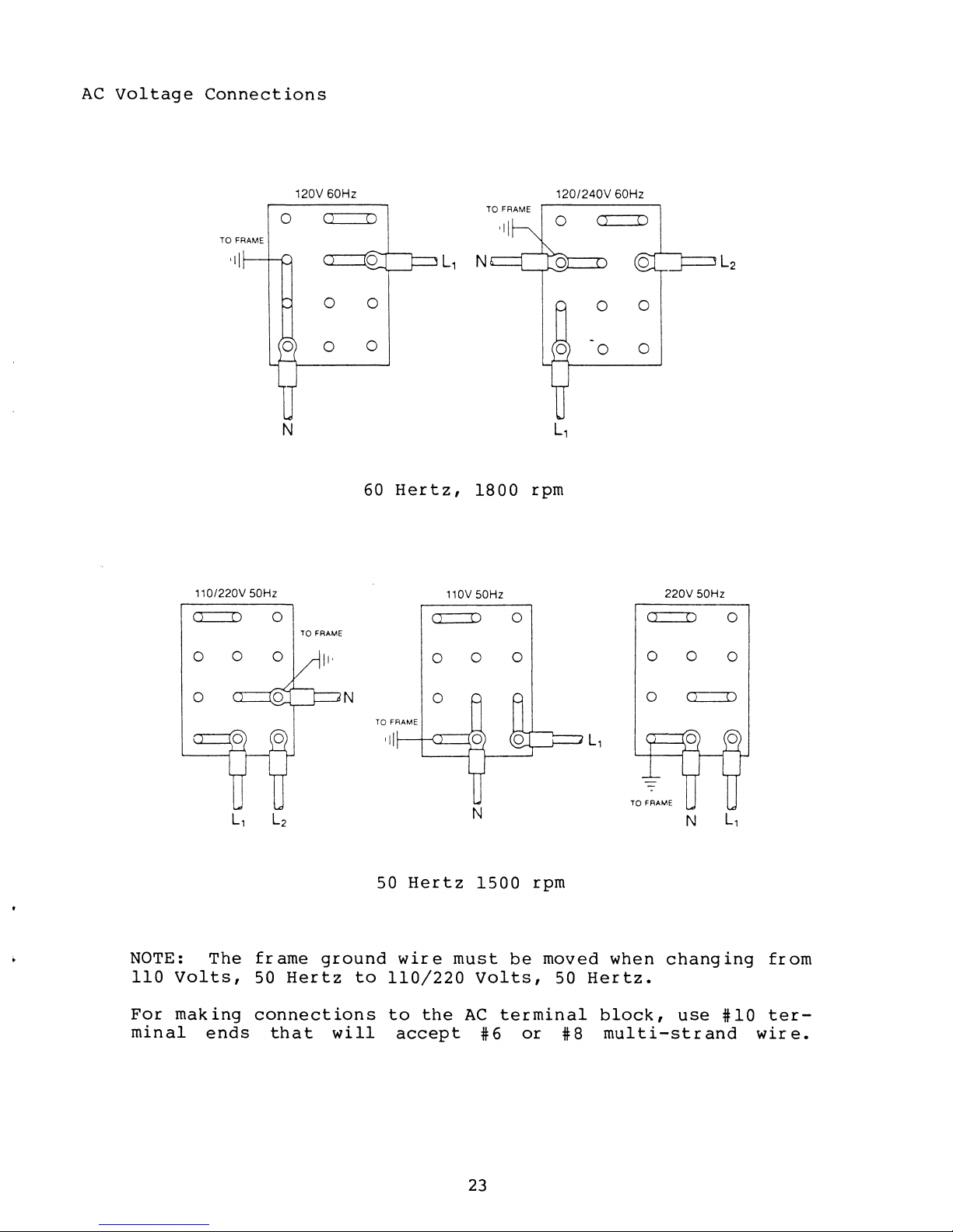
AC
voltage
Connections
TO
FRAME
'1\
, ,O/220V 50Hz
o
120V 60Hz
0
0 0
N
o
TO
<l
0
FRAME
n
0
0
60
Hertz,
o
L,
nov
TO
FRAME
120/240V
60Hz
()
N
0
0
L,
1800
50Hz
0
rpm
o o
o
o 0
L2
220V 50Hz
o
NOTE:
110
Volts,
For
minal
o
The
making
ends
--,-----<L
.. _ ..
frame
50
Hertz
connections
that
J---
N
ground
will
50
to
Hertz
wire
110/220
to
the
accept
N
1500
must
Volts,
AC
#6
--'---~-
rpm
be
moved
50
terminal
or
#8
o
L,
when
changing
Hertz.
block,
multi-strand
N
use
L,
#10
from
ter-
wire.
23
Page 30

Shore
Power
Connections
If
the
installer
must
be
done
tion-off
simultaneous
Damage
generator
~
( N
connects
by
means
transfer
connection
to
the
generator
output
Generator
___
A~_--,
G1
G2
. -
I
I
I
I
L-----/-(1)
I
_____
I
I
I
I
I
'---+------f-\!5
.---~\~7
'--------f--+-----f--I.9
I
I
I
I
I
I
switch
of
of
shore
the
shown
shore
power
SHORE
below.
power
to
the
vessel's
POWER/OFF/SHIPS
Use
to
generator
of
this
AC
GEN,
switch
output.
circuit,
center
this
posi-
prevents
CAUTION
can
result
are
connected.
NOTE: Diagram shows connections for
wire,
120-volt system. For three-wire
system
use
hot
//--
......
,
I +-_
\~
\
II
"'~-"':G:c..:~::';';:':::"~
~\
2/
"-
/--"
/ \
8 \
r64/--+~
'-
/
~_/
.---,
/
'\
\ Neutral
'f-+--+-~=--'N
______
dotted lines for
leg.
--I
'-----'L1
if
I
I
I
I
I
I
I
I
I
L-"L2
--ill'
utility
two-
the
other
Ship's Load
shore
Shlp-to-Shore
PN 32008
PN
PN
power
SWitch
32009
32010
and
•
S1
N )
y
Shore Power
24
Page 31
OPERATION
Prior
•
•
•
•
•
•
•
•
Engine
to
Lubricating
Coolant
Fuel
Sea
to
water
Battery
Generator
Exhaust
Belt
tensions
Oil
Use a good
Refer
to
capacity.
which
Fresh
the
Water
starting
oil
(fresh
engine
connections
connections
AC
connections
grade
the
Use
unit
will
Do
Coolant
the
generator,
level
water)
electrical
(governor/fresh
of
oil
API
specification
the
proper
be
operating.
not
use
check
connections
water
Spec.
section
SAE
number
CAUTION
oils
designated
SD
the
pump)
or
SE,
of
for
API
following:
preferably
this
the
manual
ambient
Spec
DS.
SE.
for
oil
temperature
sump
at
To
coolant,
engine
via
F
ill
water
inum
antifr
This
broken
ture
cooling.
avoid
the
the
and
cooling
eeze
is
to
up
will
NOTE:
filler
to
recovery
serious
never
is
hot.
remote
fr
esh
water
antifreeze.
system
and
water
ensure
and
will
provide
Ensure
neck
remove
Coolant
coolant
components
befor
that
not
freeze
the
area
tank.
injury
cooling
Use
an
e
any
gelatin-like
clog
passage
is
clear
WARNING
from
engine
should
recovery
system
antifreeze
(Alumi
placing
the
cooling
protection,
between
before
escaping
manifold
always
tank.
with
that
Guard).
in
the
globules
reduce
the
attaching
filler
be
a
eng
system
manifold
steam
added
50-50%
is
compatible
ine'
in
exchanger.
corrosion
connecting
or
scalding
cap
to
when
the
mixtur
Thoroughly
s
cooling
the
antifreeze
and
fitting
the
system
e
of
with
mix
system.
This
and
hose
alum-
aid
fr
mix-
esh
the
are
in
25
Page 32

A
coolant
supplied
be
installed
pansion
creating
the
used
coolant.
cooling
for
recovery
with
to
and
or
introducing
system.
monitor
tank
each
contraction
engine
allow
ing
(*24977)
coolant
It
should
and
and
without
air
adding
is
must
ex-
into
be
NOTE:
through
it
via
manifold
recovery
Fuel
-
Use
gasoline
clean,
Do
Vapors
explosion.
Gasoline
eventual
ide,
will
not
a
the
filtered
may
a
If
leak
be
necessary
filler
and
tank.
be
used
fill
and
engine
poisonous
death.
coolant
in
then
unleaded
when
the
spilled
is
the
to
cap
refill
unleaded
fuel
fuel
exhaust
gas
lost
system,
refill
on
the
the
gasoline
tank
gasses
that
is
not
WARNING
while
may
WARNING
ignite
can
line
available.
the
contain
cause
when
generator
causing
deadly
available.
is
a
fir
carbon
unconsciousness
Regular
running.
e
and/or
monox-
and
The
symptoms
Headache
•
Dizziness
•
Relaxed,
•
Vomiting
•
Muscle
•
Throbbing
•
If
any
generator,
~overed,
and
Regular
quired
leaks.
of
inspect
to
of
sleepy
spasms
at
these
immediately
shut
inspection
down
the
prevent
carbon
feeling
temples
the
symptoms
exhaust
and/or
monoxide
get
the
system
of
the
poisoning
are
out
generator,
for
generator
correct
26
experienced
into
the
ventilate
leaks.
potentially
are:
while
fresh
exhaust
operating
air.
the
system
deadly
the
When
compartment,
re-
is
re-
exhaust
Page 33

Starting
ventilate
attempting
tially
Starting
1.
2.
Depress
Depress
the
sufficient
Check
NOTE:
load.
Break-In
Run
Avoid
to
the
help
light
generator
Repeated
piston
the
to
explosive
sequence:
the
START
exhaust
Allow
Apply
generator
seat
the
loads
50
percent
light
rings,
generator
start
fumes
ON
the
START
switch
oil
discharge
the
only
at
engine
for
loads
resulting
compartment
the
engine.
from
switch
only.
pressure
generator
light
varying
piston
the
or
more
during
in
the
and
switch.
for
loads
loads
first
during
break-in
blow-by
The
generator
hold.
When
Allow
and
sea
to
warm
during
for
rings
100
and
for
a
minimum
ventilating
compartment
(No
load
the
a
then
water
up
before
warm-up.
the
properly.
hours
this
can
time
cause
high
on
engine
few
release
coolant
first
of
period.
improper
oil
of
5
minutes
blowers
remove
and
generator).
starts,
seconds
the
flow.
applying
25
hours
operation.
seating
consumption.
bilge.
to
ON
a
of
before
poten-
release
establish
switch.
heavy
operation
Load
of
the
the
Stopping
1.
Remove
to
2.
Depress
stopped
Generator
the
dissipate
STOP
rotating,
load
heat
switch
and
and
then
allow
stabilize
and
release.
generator
hold
operating
until
to
run
generator
unloaded
temperature.
has
completely
for
5
minutes
27
Page 34

SERVICE
AND
MAINTENANCE
Regular
the
service
Table
visually
Check
Check
Check
Clean
Check
Change
Check
Torque
Check
Clean
Check
Check
Check
Check
Check
Check
Check
Check
inspection
of
Scheduled
inspect
lube
oil
coolant
fuel
air
spark
valve
lube
supply
screen
plugs
oil
clearance
cylinder
AC
connections
and
lube
exhaust
starting
fuel
belts
zinc
sea
filters
and
anode
water
governor
timing
life
of
unit
level
level
and
head
governor
system
battery
belt
in
pump
adjustment
belt
and
servicing
the
unit
Maintenance
(flame
arrestor)
filter
bolts
linkage
tension
heat
exchanger
and
of
the
reduces
engine
repair
Daily
X
X
X
X
X
and
costs
50
Hrs.
X-I
X-I
X-I
X-I
X-I
x-I
X-I
X-I
X-I
X-I
X-I
X-I
X-I
generator
and
100
Hrs.
X
X
X
X
X
X
X
X
increases
down
300
time.
500
Hrs. Hrs.
X
X
X
X
X
X
(X-I:
NOTE:
Engine
Check
oil
Lube
lube
level
regularly.
Select
the
operation.
Temperature
Engine oil
Initial
Replace
Oil
oil
at
Use a
proper
the
50-hour
break-in
timing
level
full
good
prior
mark
brand
SAE-numbered
Ie')
W)
-30
-20
.":"}'}:'
.
i·5W~20>
.·.'."-30.
<:
<"
check)
belt
on
-20
........................................................
•.........•........
after
to
each
the
of
oil
-10
o
<.}........
··········/·····.····:·.·'OW;;
day's
dipstick.
oil
that
for
20
........
...
<[
••
::.)}:_.;~}
······;.:··?
..
·.···\/ti.·.:.:30·}·
<t·}·
...
··
".
···
1500
hours
use.
Change
meets
the
temperature
o
...::::::
..
40<>
.........
··•···
...
10
40
... ) ..
···:.:···V···2OWf··.:.:.<.o
60
}:i\
....... { ..
:(}:.3iJ/.......:.::....}.:/
•••••.....•
....
..:·····
...................
...............
}/,
...
:·
.....
of
Maintain
API
Spec.
20
m>
}}
..............
<
•.
~.!IO<
·?
...... \ .....
?:>
....
>Y//lOW;4
operation.
oil
and
condition
30 40
80
<<'IT/§ill.~.21.
....
><>
i>::i22l7.8;.:;
......
the
SC
100
··.<
filter
or
•.
...........
·····•·•·•·•··
sump
SO.
..
········
......
of
50
120
.
28
Page 35

Electric
Fuel
Pump
The
pump
eng
supplies
carburetor
A
cleanable
tained
Shut
engine
system.
fuel
men
smoking,
other
fuel
Ensure
servicing
Remove
a
wrench
it
loose
Clean
the
the
the
base
base
installed.
ine-moun
during
in
its
off
when
ts.
sources
system
the
on
the
from
screen
gasket
cover
ted
fuel
filter
base.
WARNING
fuel
when
Take
opening
Do
open
proper
the
base
hex
the
as
(:It
is
electr
to
engine
screen
service
servicing
care
filter
not
flames,
of
fire
when
ventilation
fuel
system.
cover
nut
and
bayonet
needed.
34706)
removed
ic
the
engine
operation.
is
valve
to
catch
allow
sparks
near
servicing.
by
placing
twisting
fittings.
Replace
each
and
fuel
con-
at
fuel
ele-
any
or
the
when
time
re-
Filter
Screen
Magnet
Sealing Gasket
Spark
Check
To
service
gap
Spark
Spark
Plugs
NOTE: Remove
plugs
plugs
with
for
spark
or
replace,
plug
plug
gap:
torque:
and
engine
damage
plugs,
as
needed.
0.028
10.8
install
cold.
and/or
-
(0.07
-
(1 • 5 -
clean
0.036
-
0.9
15.9
2.
spark
wear.
and
inch
mm)
Ib-ft
2 kg -m)
Wear and
Adhesion
of
Carbon
Burnt
Condition
Damage and
Deterioration
Damage
29
Page 36

Cooling
System
Monitor
scale
are
mixture.
ponents.
Maintain
sea
belt's
water
longest
tighten
tightening.
Check
the
flexible
Check
and
An
the
inner
excessively-worn
improper
Cylinder
Tighten
should
before
be
tightening
system
evident,
Use
proper
pump,
as
it
impeller
and
not
sea
wear
cooling.
Head
cylinder
cold.
coolant
flush
antifreeze
belt
three-eighths
span.
is
cracking.
water
plate.
and
Valves
head
Loosen
in
(50/50
and
that
tension
Replace
possible
in
the
pump
pump
bolts
the
sequence
clean
sea
for
will
each
antifreeeze
system
is
compatible
on
the
to
one-half
if
cracked
to
bend
water
wear
not
in
the
bolt
shown.
and
fresh
water
or
the
pump.
on
the
pump
efficiently,
sequence
one-eighth
mixture)
replenish
with
inch
deflection
fr
ayed.
governor
Ensure
front
and,
the
aluminum
circulating
shaft
the
cover,
shown.
to
one-quar
if
rust
antifreeze
engine
pump
along
Do
not
by
vanes
cam
resulting
The
ter
overover-
plate
eng
or
com-
and
the
are
in
ine
tur
n
®
.,
"0
"en
_
C
o -
.t
Tightening
® ®
Sequence
I
Head
bolt
tightening
32
-
(5.0
43.4
-
6.0
torque:
lb-ft
kg-m)
30
Page 37

Valve
time
clearance
bolts
are
should
torqued.
be
checked
and
adjusted,
if
necessary,
each
Valve
Valve
1.
2.
Clearance
(Hot)
(Cold)
Adjustment
Rotate
No.
intake
for
Rotate
Locate
stroke
1
No.
piston
and
the
the
and
cylinder
~rl
Crank angle . j
When No.1 piston
end of compression stroke.
When No.1 piston
tops of intake and end of
exhaust strokes.
the
2
cylinder
and
is
set at
is
set at
0.0079
0.0071
exhaust
beginning
Adjustment
Procedure
crankshaft
at
crankshaft
piston
the
IN
EX
IN
EX
inch
inch
the
top
valves
and
in
of
exhaust
I
I
0
I
0 0
(Both
(0.20
(0.18
in
the
in
No.
intake.
2
0\
io
normal
of
for
intake
its
1
valve
3
0
intake
rom)
rom)
its
No.1
normal
cylinder
Adjust
for
and
exhaust):
direction
compression
cylinder,
valve
for
direction
at
the
No.
3
cylinder.
No.3
the
intake
of
stroke.
the
of
end
rotation,
exhaust
cylinder.
rotation
of
valve
Adjust
valve
its
for
placing
the
for
360·.
exhaust
No.
2
31
Page 38

ENGINE ADJUSTMENT
Ignition
Attach
shaft
and
pulley
mark
referencing
Start
Check
ing
the
timing
with
Adjust
turning
on
the
tighten
NOTE:
according
Check
Timing
a
timing
timing
same.
these
engine;
with
no
load
timing
distributor
crankshaft
the
distributor
Check
generator
as
to
light
Use
two
an
on
needed
to
notch.
of
white
points
allow
ignition
the
generator
in
the
pulley
hold-down
eng
ine
the
procedure
performance
No.
it
by
desired
in
speed
1
spark
Locate
or
yellow
with
to
warm
timing
loosening
alignment
and
under
timing
the
up
light.
(61.5
direction
bolt.
adjust
given
plug
pointer
marking
timing
and
stabilize
-
62.0
distributor
with
later
load.
Timing Pointer
and
mark
crayon
light.
Ensure
Hertz).
to
place
the
timing
governor
in
the
on
front
helps
engine
engine
hold-down
the
pointer.
as
this
section.
front
gear
greatly
speed.
is
bolt
timing
needed,
crank-
case-
in
operat-
and
mark
Then
---
32
Page 39

Electric
Choke
The
choke
Some
electr
automatically
hunting
choke,
To
housing
before
The
choke
Adjust
rotating
clockwise
factory
The
choke
bient
ic
choke
will
with
avoid
no-load
burns
while
making
is
adjusted
the
for
the
to
choke
cover
set
an
may
temperature
once
be
on
choke
by
the
average
need
of
uses
a
l2-Volt
the
present
the
generator.
on
fingers
engine
is
adjustments.
with
loosening
clockwise
choke
of
rich.
70·F
readjustment
the
area
engine
when
WARNING
or
operating.
the
engine
the
to
(2l·C)
at
in
heating
starts
the
hands,
three
set
The
room
engine
which
and
generator
off
and
cover-secur
the
choke
choke
temperature.
commissioning
the
element
is
running.
do
not
Allow
at
is
initially
engine
which
is
touch
eng
room
lean
opens
started
ine
temperature.
ing
screws
and
set
for
is
to
and
the
to
counter-
the
operate.
choke
cool
at
the
on
and
the
am-
NOTE:
lower
Choke
right,
index
inboard
mark
side.
is
located
33
on
the
choke
cover:
Page 40

Carburetor
1.
Idle
Adjustment
Mixture
Jet
Disconnect
and
mixture
back
skips
turn.
NOTE:
engine
2.
Run
This
The
to
prove
Governor
The
governor
generator
voltage
The
fr
equency
governor
(Generator
reduce
screw
again;
Idle
Oil
shut-down
Mixture
mixture
idle
improve
engine
and
load.
output
ou
Data
the
engine
screw:
out
mixture
pressure
Jet
jet
mixture
eng
performance
Governor
maintains
The
of
the
will
tput
maintain
from
Plate).
throttle
speed
turn
linkage
with
screw
(counterclockwise)
turn
screw
should
clockwise
be
switch
due
to
low
(1800
is
jet
ine
rpm)
presized
adjustment
per
formance;
as
Adjustment
engine
engine
speed
generator.
engine
no-load
arm
the
idle
clockwise
slowly
satisfactory.
will
oil
at
need
pressure
the
can
the
well.
speed
determines
speed
to
full
from
stop
(in)
to
factory
be
made
governor
under
to
within
rated
the
governor
screw.
(in)
until
until
engine
one-quarter
be
jumped
at
idle.
and
in
adjustment
varying
the
frequency
3
load
Adjust
to
is
not
the
Hertz
of
control
the
engine
smooths
to
one-half
prevent
adjustable.
1800
rpm
conditions
and
of
generator
the
gener
idle
skips;
then
range
can
effects
ator
arm
im-
of
Operate
perature
NOTE:
manually
put
There
are
illustration.
1.
Increase/Decrease
This
to
set
the
arm
and
adjusted
throttle
engine
the
generator
before
voltage
three
)
adjusting
the
eng
ine.
between
throttle
full
is
attempting
If
the
adjust
before
adjusting
no-load
the
lever
to
open
not
running).
set
governor
the
proceeding
Speed
screw
speed
(The
governor
should
hold
when
to
an
linkage
points
is
used
linkage
arm
the
the
En-
bring
the
adjustment.
is
severely
at
no
with
on
of
be
engine
load
the
Carburetor Throttle Lever
to
the
adjustment.
governor.
up
out
of
obtain
Increase/Decrease Speed
to
operating
adjustment,
a
safe
(Refer
out-
to
tem-
the
34
Page 41

sure
are
this
properly
graphite
2.
Hunting/Regulation
If
variation
great,
hub.
The
increase/decrease
I f
the
the
spring
3.
Bumper
linkage
lube
adjust
governor
away
Screw
lubr
to
in
this
moves
icated.
the
engine
eyescrew
surges
from
freely
inside
speed
speed
under
the
(Disconnect
of
between
to
screw
lever
and
the
draw
load,
hub.
that
joint.)
the
may
the
the
no
load
spring
need
adjust
(Check
ball
ball
to
this
speed
and
closer
be
joint
connectors
joint
full
load
to
adjusted
eyescrew
adjustment.)
and
the
as
to
apply
is
lever
well.
move
too
This
Never
engine's
quency.
Governor
Per
iOdically
and
throttle
movement
throttle
Remove
by
popping
and
lubr
reassemble.
Governor
oil.
Do
Change
To
change
drain
all
liters)
screw
adjust
no-load
Maintenance
lubr
lever
of
this
operation.
governor
the
icate
oil
capacity
not
overfill
governor
oil,
oil.
of
SAE
is
the
ica
linkage
linkage
linkage
linkage
oil
remove
Reinstall
10W-30
used
bumper
speed;
te
link
with
end
socket
- 3
the
every
governor
engine
screw
ag e
a
graphite
arm
from
carburetor
of
ounces
governor.
500
on
engine
oil.
to
this
arm
the
and
(89
hours
from
remove
so
that
will
attaching
is
ball
arm
milliliters)
of
engine,
and
Replace
a
it
increase
lubricant
important
throttle
connector
ball
operation.
fill
fill
no-load
will
poin
or
for
with
remove
with
plug.
cause
the
ts
equivalent.
proper
arm
on
these
gr
of
SAE
oil
3
ounces
surge
an
operating
at
gover
and
governor
arms.
aphi
te
10W-30
fill
increase
nor
governor/
lube
engine
plug
(89
milli-
only.
in
fre-
arm
Free
arm
Clean
and
and
Governor
if
it
drive
becomes
Do
not
on
governor
belt
worn
or
overtighten
or
should
a
shows
the
bent
be
maintained
signs
CAUTION
governor
governor
of
shaft
35
in
cracking.
drive
will
good
belt.
condition.
Premature
result.
Replace
wear
Page 42

DC
CIRCUIT
GASOLINE
DESCRIPTION:
MARINE
GENERATOR
BTG 9 KW
SET
Safety
This
States
be
sibility
remote
compliance
these
Electrical
The
which
starter
Start
35-Amp
alternator
14.5
Wi
thin
there
is
Information
circuit
Coast
made
requirements
generator
includes
battery
DC
Volts,
is
a
manually-resettable
is
designed
Guard
to
it
by
the
to
assure
start
is
alternator.
7
inches
a
panels
with
System
internally-grounded
does
0 -
circuit
the
is
a
self-contained
charging
not
35
and
Standards
installer
that
could
Characteristics
started
have
Amps.
of
breaker
or
above
is
Its
the
the
remote
Coast
be
by
accomplished
voltage
isolation
battery
circuit
manufactured
(33
CFR
or
user.
installation
instrument
Guard
the
cause
a
conventional,
positive-engaging
to
the
regulator
diodes.
connection
which
protects
breaker.
PART
It
of
Standards.
of
injury.
engine
through
all
in
183).
is
the
panels
block.
is
DC
to
compliance
No
modifications
the
installer's
generator
are
Failure
separate
starter
a
belt-driven,
self-contained
voltage
the
subsequent
starter
with
set
installed
to
cranking
solenoid.
output
wiring.
United
may
respon-
and
12-Volt,
and
is
solenoid
any
observe
motor
The
the
13
This
1
in
-
Three
and
design
environment.
Two
the
panel
The
is
There
approximately
the
1/40th
battery.
unnecessary
operation.
months,
which
An
generator
LED
the
the
manually-operated
stop
in
panel-mounted
running
circuit.
choke
conventional,
is
ignition
of
stop
provides
optional
which
LED
LED
is
then
the
an
an
As
from
gener
the
B+
is
automatic
overspeed
2175
system.
Amp)
this
to
If
this
remote
brightens
to
alert
continues
ator
interests
fuses
circuit
with
rpm,
at
only
be
concerned
the
slight
12
Volts
a
remote
the
momentary
set.
of
are
through
and
electrically-operated.
contact
shutdown
shuts
This
all
times,
amounts
generator
drain
to
the
start
location.
at
approximately
operator
indicating
No
simplicity
installed
the
points.
which,
off
shutdown
once
to
about
with
panel
this
set
by
generator
to
that
toggle
control
and
to
protective
when
the
generator
consumes
the
18
slight
were
turning
is
available
Remote
600
release
the
switches
relays
reliability
protect
switches,
it
generator
Amp-hours
discharge
to
be
off
set.
start
engine
the
the
generator
are
are
the
The
senses
set
25
milliamps
is
unattended
main
for
panels
rpm.
starter
used
present
in
starter
and
ignition
engine
by
grounding
connected
in
a
month,
during
battery
controlling
include
The
toggle
set
is
to
in
the
marine
circuit,
the
remote
system
speed
(.025
to
normal
for
switch
a
green
purpose
switch;
running.
start
the
out
its
it
many
the
at
or
is
of
36
Page 43

An
optional
start
ing
gauge,
start-stop
for
water
con
troIs.
oil
pressure
control
temperature
remote
instrument
This
gauge,
switches,
and
panel
oil
panel
battery
and
senders
pressure.
also
is
available
includes
voltmeter,
to
be
a
water
operating
installed
which
on
includes
temper
ature
hourmeter,
the
engine
Circuit
The
during
toggle
While
switch
swi
tch
Description
two-pole
starting.
switch.
continuing
and
is
starting
generator
START
switch
Continue
tinue
holding
pressure
viding
imposs
unless
While
and
the
ible
ON
operating,
wi
11 g round
approximately
Should
the
overspeed
This
is
done
proceeding
switch
T-l
coil
itself
connection
ON
to
bypass
oper
ated
at
the
is
running.
when
depressing
the
is
sufficient
normal
to
energ
switch
2175
generator
circuit
by
simply
with
is
switch
The
second
to
hold
to
generator
the
green
the
ON
switch
B+
path
ize
is
depressed.
the
overspeed
the
ignition
rpm.
~
the
normal
faulty
and
bypasses
pole
the
the
protective
cause
set,
If
starting
LED
ON
switch.
after
to
close
to
the
shut
be
starter
down
reset
depressing
starting
and
check
resetting
for
the
provides
ON
switch
the
starter
release
brightens.
releasing
the
the
ignition
This
shutdown
system
from
in
the
spark
shutdown
at
a
It
oil
wh
ile
protects
if
order
STOP
procedure.
will
at
protective
a
source
to
provide
to
crank
the
START
remote
is
only
the
pressure
system.
the
the
module
it
sense
an
overspeed
to
switch
not
plugs.
shutdown
of
switches,
location,
necessary
START
safety
gener
ator
starter
monitors
s
restart
momentarily
If
correct
B+
to
B+
to
the
eng
switch
switch
switch,
Note
motor
engine
eng
ine
condition,
the
the
it,
switches
the
the
the
ine.
when
release
to
until
that
is
running,
gears.
speed
generator.
and
overspeed
lift
START
START
START
If
the
the
con-
oil
pro-
it
is
speed
at
the
then
the
It
is
very
installed
shutdown
be
a
cause
nor
fail
To
stop
the
normally-closed
must
panels
remote
the
installed.
be
depressed
may
start/stop
eng
ine
be
con
Refer
important
and
functioning.
module
of
injury
and
cause
generator,
B+
path
(opened)
connected
panel
trol
to
which
panel
the
WARNING
that
would
should
the
generator
depress
to
the
ON
until
to
the
the
schematic.
when
engine
the
Any
overspeed
tampering
cause
the
generator
the
and
generator
generator
A
either
DC
wiring
37
it
to
run
STOP
START
jumper
of
shutdown
with
to
malfunction,
belt-driven
away.
switch
switches.
comes
set
to a stop.
as
wire
the
opt
schematic.
the
which
The
illustrated
must
be
ional
always
overspeed
could
gover-
opens
STOP
Remote
removed
panels
be
switch
start
in
is
the
the
from
in-
Page 44
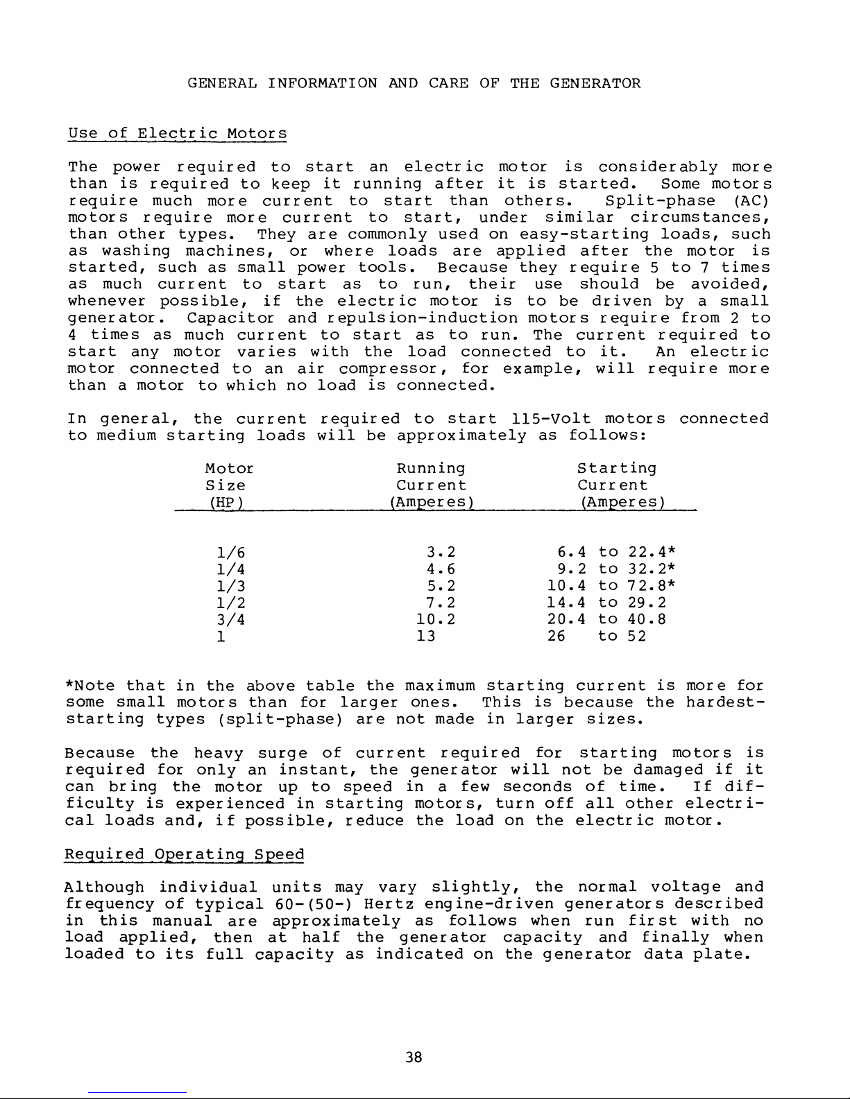
Use
of
GENERAL
Electric
INFORMATION
Motors
AND
CARE
OF
THE
GENERATOR
The
than
power
is
require
motors
than
as
other
washing
started,
as
much
whenever
generator.
4
times
s
tart
motor
than
In
to
any
connected
a
general,
medium
required
required
much
require
types.
such
current
possible,
as
mo
motor
starting
to
more
more
machines,
as
small
to
Capacitor
much
tor
current
var
to
to
which
the
current
Motor
Size
(HP)
1/6
1/4
1/3
1/2
3/4
1
to
start
keep
current
current
They
are
or
power
start
if
the
and
ie s with
an
air
no
loads
an
electr
it
running
to
to
commonly
where
tools.
as
electr
start
loads
to
start,
run,
ic
after
used
Because
motor
repulsion-induction
to
start
the
as
load
compressor,
load
required
will
is
connected.
to
be
approximately
Running
Current
(Amperes
3.2
4.6
S.2
7.2
10.2
13
ic
motor
it
than
under
on
are
applied
their
is
to
run.
connected
for
start
)
is
is
started.
others.
similar
easy-starting
they
require
use
to
be
motors
The
to
example,
11S-Volt
follows:
as
6.4
9.2
10.4
14.4
20.4
26
considerably
Split-phase
circumstances,
after
should
driven
require
current
it.
will
motor
Starting
Current
(Amperes)
to
22.4*
to
32.2*
to
72.8*
to
29.2
to
40.8
to
S2
Some
loads,
the
5
to
be
by
from
required
An
require
s
connected
more
motors
(AC)
such
motor
7
times
avoided,
a
small
2
electr
more
is
to
to
ic
*Note
some
starting
Because
required
can
ficulty
cal
Required
Although
frequency
in
load
loaded
that
small
bring
loads
this
applied,
in
motors
types
the
for
the
is
experienced
and,
Operating
individual
of
manual
to
its
the
above
than
(split-phase)
heavy
only
an
motor
if
possible,
Speed
typical
are
then
full
surge
instant,
up
units
60-(SO-)
approximately
at
capacity
table
for
to
in
half
larger
are
of
current
speed
starting
reduce
may
Hertz
the
as
the
maximum
ones.
not
the
generator
in
motors,
the
vary
as
generator
indicated
38
starting
This
made
in
larger
required
will
a
few
seconds
turn
load
on
slightly,
engine-driven
follows
capacity
on
the
current
is
because
for
not
off
the
electric
the
normal
generators
when
generator
sizes.
starting
be
of
time.
all
other
run
and
is
the
motors
damaged
motor.
voltage
described
first
finally
data
more
hardest-
if
If
dif-
electri-
with
when
plate.
for
is
it
and
no
Page 45

Load
Applied
4-Pole
Speed
(rpm)
Frequency
(Hertz)
Generator
l20V
(110)
plants
Voltage
240V
Plants
(220)
The
output
operation
If
an
AC
load,
check
Preventive
Maintenance
•
•
Keep
Ensure
ing
the
AC
chaffing.
None
Half
Full
voltage
of
the
voltmeter
it
with
Maintenance
on
the
generator
all
connections
voltage
1830
(1530)
1800
(1500)
1755
(1455
)
should
generating
or
ammeter
a
portable
generator
clean,
are
62
(52
60
(50)
59
(49
be
checked
plant
is
meter
is
dry
are
clean
properly
)
(112
(110)
)
(100)
and
not
and
minimal.
and
well-ventilated.
and
supported
122
)
120
110
periodically
the
appliances
installed
amprobe.
tight
244
(224
240
(220)
220
(200
to
and
and
)
)
to
it
supplies.
monitor
that
protected
ensure
voltage
cables
proper
and
carry-
against
•
The
maintenance
replace
General
A
complete
Generator
through
rear
armature
is
it.
Troubleshooting
is
your
and
local
illustrated
furnished
bearing
required.
dealer.
in
is
If
text
the
lubricated
the
bearing
on
troubleshooting
Technical
and
sealed;
becomes
Manual
that
therefore,
rough
the
is
or
noisy,
9
KW
available
no
BTG
39
Page 46

ENGINE TROUBLESHOOTING
Engine
to
start
Engine
cranks
does
Trouble
but
not
crank
fails
1.
2.
3.
4.
5.
6.
7.
8.
9.
10.
11.
12.
1.
2.
3.
4.
5.
6.
7.
possible
Out
Engine
Filters
of
fuel
flooded
clogged
fuel
voltage
drop
switch
Worn
Bad
or
faulty
ignition
High-tension
(system
wet)
Automatic
Fuel
pump
clogged
Filter
Faulty
and
(Lift
Engine
Battery
Sea
Loose
Voltage
in
overspeed
start)
Tl
circuit
low
water
battery
drop
solenoid
Bad
starter
Faulty
Engine
START
DC
tripped
Cause
at
spark
coil
leads
shutdown
inoperative,
carburetor
coil
connection)
breaker
or
dead
in
cylinders
connection
at
terminal
solenoid
switch
circuit
by
contaminated
(+)
on
plugs
grounding
switch
clogged
switch
starter
breaker
overspeed
faulty
filter
(reset
tripped
Engine
shuts
Backfire
starts,
down
through
runs
carburetor
and
1.
2.
3.
4.
5.
6.
7.
1.
2.
3.
4.
5.
6.
Faulty
switch
Faulty
and
start,
switch
Faulty
Faulty
Engine
Dirty
Low
fuel
oil
Ignition
Engine
Choke
Plug
stuck
wires
order
Distributor
Dirty
air
automatic
overspeed
lift
will
fuel
STOP
not
pump
switch
circuit
filters
level
in
timing
flooding
closed
wrong -check
cap
cleaner
shutdown
switch
Tl
coil
reset.)
breaker
sump
wrong
cracked
(reset
if
tripping
firing
40
Page 47

ENGINE
TROUBLESHOOTING
(continued)
Engine
Engine
Engine
Trouble
overheating
hunting
misfires
Possible
1.
2.
3.
4.
5.
6.
7.
8.
1.
2.
3.
4.
5.
6.
7.
8.
1.
2.
3.
4.
5.
6.
Cause
Coolant
loss
(Pressure
Belts
Sea
Sea
Faulty
loose
water
water
hose
Thermostat
Exchanger
Faulty
gauge
thermometer)
Throttle
Dirty
fuel
Defective
Governor
Valves
out
Generator
Cracked
Faulty
distributor
high-tension
Ignition
Spark
Valve
Dirty
Dirty
Poor
plug
clearance
carburetor
air
quality
test
pump
pump
or
system)
broken
impeller
worn
stuck
clogged
(check
linkage
filter
fuel
out
pump
of
of
adjustment
overloaded
timing
worn
cleaner
fuel
faulty
closed
with
binding
adjustment
leads
wrong
incorrect
High
Low
oil
No
DC
battery
Black
Blue
oil
pressure
pressure
charge
exhaust
exhaust
to
start
smoke
smoke
1.
Faulty
2.
Relief
3.
Dirty
1.
Low
2.
Faulty
3.
Wrong
4.
Stuck
5.
Faulty
1.
Connections
loose
2.
Faulty
3.
No
IG
1.
Dirty
2.
Choke
3.
Carburetor
1.
Worn
2.
Worn
3.
Lube
4.
Crankcase
gauge
valve
or
wrong
oil
level
gauge
SAE
relief
oil
or
faulty
alternator
excitation
terminal
air
stuck
or
misadjusted
or
unseated
oil
diluted
stuck
SAE
oil
valve
pump
to
alternator
to
intake
closed
flooding
breather
oil
alternator
valves
piston
hose
rings
clogged
41
Page 48

TABLE
OF
TIGHTENING
TORQUES
Cylinder
Main
Connecting
Front
Flywheel
Rocker
Spark
Exhaust
to
Camshaft
Oil
Banjo
bearing
crankshaft
cover
plugs
cylinder
pan
bolt-oil
head
rod
retaining
and
intake
head
timing
bolts
hold-down
caps
bearing
pulley
cap
nuts
manifold
belt
drain
bolts
pulley
hose
bolts
cap
36.2
39.0
15.2
65.2
28.9
5.8
10.8
7.2
21.7
2.9
18.1
lb-ft
-
-
-
-
-
- 8
-
-
-
-
-
43.4
47.7
21.0
72.4
36.2
.7
15.9
11.
32.5
5.1
25.3
6
5.0
5.4
2.1
9.0
4.0
0.8
1.5
1.0
3.0
0.4
2.5
kg-m
-
-
-
-
-
-
-
-
-
-
-
6.0
6.6
2.9
10.0
5.0
1.2
2.2
1.6
4.5
0.7
3.5
Oil
pump
Rear
Balance
Timing
Oil
Balance
Distributor
Distributor
Backplate
Generator
Drive
oil
pump
disc
to
seal
shaft
belt
drive
shaft
engine
tensioner
housing
to
to
block
drive
to
block
retainer
thrust
shaft
gear
rotor
cover
distributor
disc
plate
gear
to
to
shaft
block
housing
flywheel
10.8
7.2
7.2
21.7
7.2
7.2
2.9
10.8
7.2
14.5
28.9
-
-
-
-
-
-
-
-
-
-
-
15.9
11.
10.8
30.5
11.
11.
5.1
15.9
11.
21.7
39.8
6
6
6
6
1.5
1.0
1.0
3.0
1.0
1.0
0.4
1.5
1.0
2.0
4.0
2.2
-
1.6
-
1.5
-
4.5
-
1.6
-
1.6
-
0.7
-
2.2
-
1.6
-
3.0
-
5.5
-
42
Page 49

TABLE
OF
STANDARD
HARDWARE
TIGHTENING
TORQUES
unless
torque
Grade
Grade
Gr
ade
stated
values
4T
6mm
8mm
10mm
10mm
12mm
12mm
12mm
13mm
14mm
14mm
16mm
16mm
6T
6mm
8mm
10mm
10mm
12mm
12mm
12mm
7T,
6mm
8mm
10mm
10mm
12mm
12mm
12mm
13mm
14mm
14mm
16mm
16mm
when
bolt/nut
bolt/nut
bolt/nut
bolt/nut
bolt/nut
bolt/nut
bolt/nut
bolt/nut
bolt/nut
bolt/nut
bolt/nut
bolt/nut
bolt/nut
bolt/nut
bolt/nut
bolt/nut
bolt/nut
bolt/nut
bolt/nut
and
8T
bolt/nut
bolt/nut
bolt/nut
bolt/nut
bolt/nut
bolt/nut
bolt/nut
bolt/nut
bolt/nut
bolt/nut
bolt/nut
bolt/nut
otherwise
tightening
8.8
for
pitch
1
1.
1.
1.5
1.
1.5
1.
1.5
1.5
2
1.5
2
1
1.
1.
1.5
1.25(ISO)
1.5
1.
1
1.
1.
1.5
1.
1.5
1.
1.5
1.5
2
1.5
2
specific
a
standard
25
25
25
(ISO)
75
25
25
75
25
25
25
(ISO)
75
assembly,
hardware.
2.9
7.2
13.7
13.0
25.3
25.3
21.7
32.5
36.2
34.0
54.2
51.
4.3
10.8
21.
7
19.5
36.2
36.2
34.7
5.8
14.5
2B.9
26.B
54.2
50.6
43.4
57.9
72.3
6B.7 -101.
10B.5
101.
Ib-ft
4
3 -
-
-
-
-
-
-
-
-
-
-
-
-
-
-
-
-
-
-
-
-
-
-
-
-
-
-
-
-
-
5.1
11.6
22.4
21.
39.8
39.8
36.2
50.6
57.9
55.7
79.6
76.7
6.5
15.9
32.5
30.4
57.9
50.6
49.2
8.7
21.
39.8
37.6
75.9
65.1
61.5
86.8
108.5
166.4
159.1
use
7
7
3
following
the
kg-m
0.4
-
1.0
-
1.9
-
1.
8 -
3.5
-
3.5
-
3.0
-
4.5
-
5.0
-
4.7
-
7.5
-
11.
7.1 -10.6
0.6
-
1.
5 -
3.0
-
2.7
-
5.0
-
5.0
-
4.8
-
0.8
-
2.0
-
4.0
-
3.7
-
7.5
-
10.5
7.0
-
-
6.0
8.0 -12.0
10.0
15.0
14.0
-
15.0
9.5 -14.0
-
-
0.7
1.6
3.1
3.0
5.5
5.5
5.0
7.0
8.0
7.7
0
0.9
2.2
4.5
4.2
8.0
7.0
6.8
1.2
3.0
5.5
5.2
9.0
8.5
23.0
22.0
Gr
ade
5
1/4
1/4
5/16
5/16
3/8
3/8
7/16
7/16
1/2
1/2
capscrew
UNC
UNF
UNC
UNF
UNC
UNF
UNC
UNF
UNC
UNF
11
1B
21
28
30
44
50
68
73
9
11
13
20
23
33
35
49
55
73
80
1.2
1.
2.5
2.9
3.7
4.1
6.1
6.9
9.4
10.1
5 -
-
-
-
-
-
-
-
-
-
1.5
1.8
2.8
3.2
4.6
4.8
6.8
7.
10.1
11.1
6
 Loading...