

Page 1

OPERATORS
. -
-
8~:5;!Kw.
..
BTG
·,
50Hz
MANUAL
·6.8Kw
BTG
50Hz
8.5Kw
12.5Kw
15.0Kw
MARINE
BTGA
BTG
BTG
GASOLINE
~,.._.
rWESTERBEKE
J
J
MYLES
WEBSITE:
am.,_.
NAIHA
......
6,0Hz
60Hz
6.8Kw
10.0Kw
60Hz . 12.0Kw
GENERATORS
PUBLICATION
REVISIONS
-MARCH2018
WESTERBEKE
STANDISH
WWW.WESTERBEKE.COM
Member
CORPORATION
INDUSTRIAL
Ntditmal
.
#035909
•150JOHN
PARK • TAUNTON
Marine
MllnufacturersAssoclaJion
HANCOCK
MA
02TBo
BTGA
BTG
BTG
ROAD
50Hz
50Hz
50Hz
Page 2

CALIFORNIA
PROPOSITION
WARNING
Exhaust
gasoline
its
the
cancer,
reproductive
Exhaust
colorless
unconsciousness
exposure
•Dizziness
gas
from
engines
constituents)
state
of
California
birth
defects,
harm.
gasses
gas.
can
contain
carbon
and
include:
•NaiiSea.
•Headache
•
Weakness
IF
YOU
SET
seek
until
OR
ANYONE
OUT
INTO
medical
it
bas
and
Sleepiness
THE
attention.
been
inspected
65
diesel
and
(and
some
of
are
known
to
to
cause
and
other
A
WARNING:
Carbon
Monoxide
death.
ELSE
FRESH
Monoxide,
is
poisonoiiS
SympfDms
•
•
•
•Inability
EXPERIENCE
AIR
IMMEDIAmY.
Shut
down
and
repaired.
of
Throbbing
Muscular
Vomiting
ANY
the
unit
an
odorless
and
Carbon
in
Temples
Twitching
to
Think
OF
THESE
If
symptiJ!US
and
do
and
can
cause
Monoxide
Coherently
SYMPTOMS,
persist,
not
restart
A
WARNING
should
be
generator.
WESTERBEKE
MONOXIDE
of
your
vessel.
obtainable
DECAL
is
provided
fixed
to a bulkhead
also
recommends
DETECTORS
They
at
your
in
are
local
by
WESTERBEKE
near
your
installing
the
living/sleeping
inexpensive
marine
store.
engine
CARBON
and
easily
and
or
quarters
Page 3

Gasoline
with
an ETHANOL
content
higher
· and
than
may
10°/o (E10)
void
warranty.
is
not
allowed
AJ~
~
•WESTERBEKE™
Engines &
Generators
Page 4

Blank
page
Page 5

SAFETY
INSTRUCTIONS
'INTRODUCTION
Read
this
safety
manuol
caused by foilure
precautions.
. toke the
perso~eJ.~
As
the.dftmer
and
advisories
Is
in
·
stimdatd8;
in
the
potential
l'1lfiln1enarlce
to
the
:PREVENT
A
wblle
power.l.etha/
1111
Do not operate
enclosures and
111
Shut off electrical
equipment
111
Use ilisulated mats whenever working on electrical
equipment
111
Make
(particularly shoes) when
Ill
Remove wristwatch and all
electrlca1
PREVENT
A
exhallst
Know
necessary
your
or
ope(8toF,
provided
af1g11menfwitft
hovrevel;
followilg
E!rKI
ar;:tual
pages.
aCiMlies.
QWRef/operator.
ELECTRIC
WARNING:
engine
is
voltage
sure your clothing and skin are dry, not damp
equipment
BURNS-
WARNING:
system
hot!
111
Monitor engine antifreeze coolant level at the plastic
coolant recovery
location on the water jacketed exhaust manifold, but only
when the engine
A
WARNING:
1111
In case
before touching
of
an
engine overheat, allow the engine
carefully.
to
follow
fundamental
when
dangerous
precautions
machinBr!:
always~
for
your
the~
safety
riSks
The
responsNlyforthe
risks
for
comp(tanCe
and
other
Most
accidents
rules
conditions
to
protect
_
..
_ _
the
and
Yacht
limited
with
following
all
belong
c:onvenience.
Boat
are
not
conditions
SHOCK
Do
not.
trlllt:h
Ai:
electrical
ruDlling,
tbis
covers
components. A tullning
or
when
oolmecteil
is
present
machinery without electrical
in
,power
HOT
Do
llot-tDut:h
tank and periodically
is
COLD.
Steam
can
the
engine or checking the coolant.
at
th~
place.
before accessing electrical
handling electrical equipment
jewelry
when working on
ENGINE
hot
engl11e
cause
injury
and
exist
yourself,
,safe#¥
1his
safely
Cormcil
to
the
lnfonnation
ldenfilication
safety~~
eXClusiVely·
CtJIIIIectitms
tD
shore
titJDllections!
parts
or
engine
gets
at
the filler cap
or
death!
are
and
your
roles
information
(
ABYC)
of
very
to
cool
PREVENT
I A
111
Prevent
sparks to
pump, or other potential
vapors.
removing the fuel
111
Do not operate with the
Backfire can
Ill
Do
the fuel system.
engine/generator clean and free of
chan~
1111
Be
PREVENT
. A
injury
1111
•Follow
hatches closed when fueling. Open
after fueling.
running
before
111
All
when
ventilated area away from spark-producing equipment
and
-
Ill Do not fill the fuel tank(s) while the engine is running.
111
Shut'·off
the
spill. DO NOT allow any
SQl.n"ceS
servicing.
the fuel system.
Ill Do not alter
Ill
Be sure all fuel supplies have a positive shutoff
Ill
Be certain fuel line fittings are adequately tightened
free
1111
Make sure a fire extinguisher is installed nearby and is
properly maintained. Be
Extinguishers rated ABC by
for all applications encountered
BURNS-
WAJIIIIIIG:
:6ash
fires. Do not smoke or permit
occur near the carburetor, fuel line,
Use a suitable container to
cause
not smoke or permit flames or sparks to occur near
of
fire;
aware-
diesel fuel
BURNS-
WARNING:
or
death!
n>-fueling
Check
the
blower. Run
starting
fuel
vapors
handling and storing fuels. Store fuel in a well-
out
of
the reach
the
fuel
fue~
system.
of
fire near
Ensure proper ventilation
or
of leaks.
FIRE
F/rB
..........
line, carburetor, or fuel filters.
air
severe injury or death.
Keep
the
Wipe
up all spilled fuel and engine oil.
will
/tljtlry
Dr-
sources
of
spilled
catch
cleaner/silemcer
compamnent and the
debris
burn.
EXPLOSION
ExploslollS
safety
your engine. · ·
are
highly
service valve at the engine
Thke care
the
modify the fuel system.
from
fuel
'llllfJOI'S
instructi.OJ:!S.
below for fumes/vapor before
the
blow~
explosive.
of
children.
in
ca~b4J.g
smoKing,
fuel
system or
familiar with its
the
Keep the vessel's
and
for
Use
any fuel that
open
engine
exists
NFPA
in
~
flames
filter,
fuel
or fuel
all fuel when
removed.
to minimize
t:a11
t:aiiSII
ventilate
four minutes
extreme
are
environment
cabin
care
when
servicing
flames, or other
when
when servicing
valve.
proper
use.
apptopriate
or
fuel
the
might
and
Engines & Generators
i
Page 6

SAFETY
INSTRUCTIONS
ACCIDENTAL
A
WARNING:
or
death!
•
Thm
unit's
engine.
•
Make
starting.
•
Make
re-installed before starting the engine.
BAnERY
A
WARNING:
or
death!
• Do not smoke or
being serviced. Lead
highly explosive
arcing
equipment in the
during
• Never connect
positive ( +) connection terminal of the starter solenoi?.
Do
not
together.
Ventilate
accumulation of explosive
disturb the battery charger connections
is
being charged.
•
Avoid
burns or sparks that could cause
wristwatch, rings,
the
battery.
•
Always
the
battery connections
and
BATTERY
A
WARNING:
severe
• When servicing
level,
protection. Batteries contain sulfuric
destructive.
it off at once
into the
caps.
STARTING
Accidental
OFF
the
DC
breaker on the control panel or
battery
selector
certain all personnel
certain
all
covers,
switch
guards,
starting
to
are
can
OFF
before
clear of the engine before
and hatches
EXPLOSION
Battery
or
by
lit tobacco products. Shut off
servicing.
the
test the battery condition by shorting
Sparks could ignite battery
any
compartment containing batteries
contacting
turn
the
reconnect it last
explosion
allow
an
acid
gas,
which can be ignited
vicinity
battery charger off before disconnecting
to
negative(-) battery cable
the
terminals with
and
any
..
Remove the
when
can
open
flame
batteries emit
prevent electrical
gases.
To
an
explosion. Remove
other jewelry before handling
servicing the
ACID
injury
or
death!
wear rubber
If
it
with
eyes
inadvertently when removing electrolyte
Sulfuric
the
acid
in
batteries
battery or checking the electrolyte
gloves,
comes
water.
a rubber
in
contact with your
Acid
may
apron,
splash
cause
servicing
are
cause
near the battery
hydrogen,
by
all
to
the
gases
or
avoid
sparks,
while
tools,
etc.,
negative
battery.
can
and
acid
which
skin,
on
injury
tum
the
the.
Injury
a
ele~cal
electncal
arcing
the
termmals
fuel
vapors.
to
prevent
do
not
the battery
to
prevent
lead
first
cause
eye
is
wash
the
skin or
TOXIC
• Ensure that the exhaust system
•
•
EXHAUST
A
WARNING:
discharged from
regularly
water-injected
Be
sure
the
Run
blowers when running
Do
not
run the generator set or engine unless the boat
equipped with a functioning marine carbon
detector that complies
boat builder or dealer
detectors.
• For additional information, refer
(educational information
A
WARNING:
odorless
nausea
•
• Do
•
AVOID
A
or
•
gas.
or
Do
not
use
Diesel
fumes
systems.
copper tubing resulting in exhaust/water leakage.
not
install exhaust outlet where exhaust can be
through portholes, vents, or air conditioners.
exhaust discharge outlet
enter
the
flow
of exhaust.
Although
exhaust
gas
is
present in
symptoms
poisoning
Vomiting
Dizziness
Headache
Nausea
MOVING
WARNING:
death!
Do
not
service
situation arises in
make
operating adjustments, use extreme care
touching moving parts
components.
GASES
Carbon
the
for
leaks and
elbow
unit
and
Carbon
Inhalation
monoxide
engine.
make
is
securely
its surroundings
with
for
installation of
on
monoxide
produces
(CO}
Is a deadly
is
adequate to
Check
the
exhaust
sure
the exhaust manifold/
attached.
are
the
generator set or
ABYC
A-24.
to
ABYC
Carbon
Monoxide).
(CD}
is
flu·llke
death!
copper tubing in diesel exhaust
can
rapidly
destroy
Exhaust sulfur causes rapid deterioration of
is
exhaust
fumes
discharge
Avoid
overloading
diesel engine exhaust
from
gasoline
diesel
exhaust
or
signs
of
carbon
are:
Inability
Throbbing in temples
Muscular twitching
Weakness
copper
near the waterline, water
outlet and
engines,
monoXlde
close
the
gases
are
carbon
fume~.
S?me
to
think coherently
and sleepiness
PARTS
Rotating
the
engine
which
parts
can
cause
while
it
is
it
is
absolutely necessary
and
hot exhaust system
running.
gas!
expel
system
well
ventilated.
engine.
monoxide
Consult
approved
an
your
TH-22
invisible
symptoms,
systems.
tubing
in
exhaust
If
the
or restrict
craft.
not
as
toxic
monoxide
of.
the
mhalation
injury
If
a
to
avoid
gases
is
drawn
engine
could
the
as
or
to
Engines & Generators
ii
Page 7

1!11
Do
not
wear
loose
clothing
equipment;
jackets,
could
1:1
Make
Keep
places
19
Do
not
the
engine
!1il
Do
not
the
exhaust
generator
death
4kW:«\RNING:
I(J~!
II
Never
1'1
Do
not
flame
1!11
Do
not
open
A
WARNING:
mentally
tie
shirts,
be
caught
sure
all
protective
at
all
times.
check
is
operating.
allow
any
discharge
is
operating.
can
occur.
operate
run
the
arrester
run
engines
{when
installed).
or
physically
back
sleeves,
in
moving
attaching
shields
fluid
levels
swimming
High
an
engine
engine
removed.
Do
not
or
jewelry when servicing
long
hair
and
rings,
necklaces
parts.
hardware
and
guards
or
the
drive
or
activity
opening
Carbon
noise
with
for long
work
for
Monoxide
levels
without
the
periods
on
air
machinery
incapacitated
SAFETY
avoid
wearing
or bracelets
is
properly tightened.
in
their respective
belt's tension
around or
the
generator
can
cause
its
muffler installed.
intake (silencer)
with their enclosures
by
fatigue!
loose
while
poisoning
hearing
when
you
INSTRUCTIONS
that
while
near
or
or
ABYC,
INSTALLING
Read
for
tions
AB:YC
"Standards
Craft"
Order
the
Order
Order
are
NFPA
the
following ABYC, NFPA and
safety codes
.when
installing your engine.
(American Boat and Yacht
and
from:
ABYC
613 Third Street,
Aprtapolis,
www.abycinc.org
NFPA-
"Pleasure and Commercial Motor Craft"
National Fire Protection Association
Battery Match
Quincy,
USCfl(Uritted
"regulatedions
Code of Regulations"
U.S. Government Printing Office
Washington,
No.302 (National Fire Protection
from:
MA 02269
from:
AND
USCG
PUBLICATIONS
ENGINES
and
Technical Information
MD
Park
are under titles
D.C.
AND
GENERATORS
standards. Follow their
St1ite
10
21403
States Coast Guard)
CFR33
20404
USCG
Council)
Reports
and
FOR
publications
recommenda-
for
Small
Association)
CFR46
of
the
OPERATORS
Many
of
in
your
notes
to
carefully,
procedures.
GASOLINE
Preparations
begin
with
Yacht
Council's
a
combination
Sections
H-2
Ventilation
·
H-24
Gasoline
P-1
Installation
for
P-4
;M:arine
EllAC
All
installations
Regulations
www.abycinc.org
MANUAL
the
preceding
Operators
highlight
maintain
ENGINE
to
install
a
thorough
(ABYC)
of
of the
ABYC
.for
Fuel'
of
Propulsion
Inboard
and
DC
Electrical
must
(FCR).
critical
sources
safety
tips
and
warnings are repeated
Manual
along
with
other
<;autions
information. Read
your
equipment, and follow
AND
GENERATOR
a gasoline
examination of the American Boat
standards of particular interest
Boats
Systems
Exhaust
and
Auxiliary Engines
Engines
comply
engine
standards. These standards
tnc~uding
using Gasoline
Systems
Systems
the
and
Transmissions
on
with
the
yoU:r
INSTALLATIONS
or generator should
USCG and
Boats
Federal Code of
manual
all
safety
and
are·
the
and
from
NFPA.
are:
Engines
iii
& Generators
Page 8

When
installing
attention be paid to the
WESTERBEKE
INSTALLATION
following
engines
information:
and
generators
it
is
important that strict
CODES
Strict
when
AND
federal
installing
REGULATIONS
regulations,
engines
and
SIPHON-BREAK
For installations
or
will
be below the vessel's
break in the
minimum
the exhaust manifold
raw
water
If
you
have
to
the
vessel's waterline under
siphon-break.
NOTE:
A
siphon-break
operation.
engine
damage.
EXHAUST
The exhaust system's hose
Exhaust
and
and
system
under
Hose
turns
turns.
MUST
any
where
the
raw
water supply hose
of
20"
above
the
injection
damage
Failure
any
doubt about
Consult
to
the
requires
to
properly
SYSTEM
is
recommended.
without
the
Iieed
In
this
regard, a single length of corrugated exhaust hose
be
designed
sea conditions
ABYC
guidelines,
generators
exhaust manifold/water injected exhaust
waterline,
to
vessel's waterline.
port
is
engine
and
the
position of
the
vessel's various operating conditions,
periodic inspection and
maintain a siphon-break
the
siphon-break
MUST
of additional
and
to
prevent
at
The
any
be
use
angle of
and
in
a marine
provisions
the
exhaust
Failure
at or
below
possible
certified for
the
flooding
the
water-injected exhaust elbow relative ·
manufacturer
of
this
type
fitting
and
entry of
vessels
safety
codes
environment.
must
be
elbow.
This
to
use
the load
of
cleaning
can
for proper
marine
use.
of hose
clamps
water
into
heel.
must be complied
made
a siphon-break
waterline
the
result
allows
to
the
elbow
is
close to
to
install a siphon-
hose
must
be looped a
when
wiU
result in
boat.
instaU
to
ensure
proper
in
catastrophic
maintenance.
Corrugated Marine
for
extreme bends
accomplish these
can
be
used.
exhaust system
with
a
bends
The
•.
AVAILABLE
YOUR
WESTERBEKE
'DEALER
:·s/PHON4fREAiWirif
LOOP'
FROM
STAINLESS
A
detailed
engines
to
and
download
Marine
Installation
generators,
from
our
Manual
is
supplied
website
Engines & Generators
with
at
www.westerbeke.com.
iv
covering
each
gasoline
unit. A pdf
and
diesel,
is
available
Page 9

TABLE
Parts
Identification
Introduction
Fuel,
Engine
Control
Operating
Generator
The
Alarms
Maintenance
Fuel
Cooling
Engine
Remote
Carburetor
Engine
Alternator
Engine
Lay-up
Wiring
Generator
BT
12
BT
Voltage
BT
BTGJBTGA
Panels
Dally
Routine
and
System
Fuel Lift Pumps .....................................................
Gasoline/Water Separator ...................................... 12
System
Changing Coolant .................................................. 13
Heat Exchanger ..................................................... 14
Replacing the Thermostat ...................................... 14
Raw Water Intake Strainer .................................... 15
Raw Water Pump ................................................... 15
Lubricating
Changing the Oil Filter .......................................... 16
011
Adjustments
Electric Choke ....................................................... 19
Engine Compression .............................................. 19
Ignition Wires ........................................................ 19
Valve Clearance ..................................................... 20
Pressure ........................................................... 20
Oil
Spark Plugs ............................................................ 21
Drive Belt Adjustment. .......................................... 21
Govemor ................................................................
12
Volt
Troubleshooting
and
Diagrams
Generator
Stud
Internal
Single
Regulator
Generator
BTG
12.5Kw
BTG
15.0Kw
Metric
Conversion
OF
CONTENTS
....................................................
................................................................
011,
and
Engine
Coolant
........................
............................................................
Instructions
Break·ln
................................................
Procedure
...................................
.......................................................
Circuit
Breakers
Schedule
.............................................
......................................
..............................................................
.........................................................
Oil
..............................................
Filter
......................................................
Adjustments
...........................................
..................................................
Testing
DC
....................................................
Circuit .................................................
............................................
Recommissioning
and
Schematics
Information
..............................................
Description
Wiring
Phase
Wiring
Adjustments
Troubleshooting
8.5Kw
Speclfications
Specifications
Speclficatlons
Data
.................................
.......................
.........................................
Schematic
Schematic
.........................
..........................
...............................
............................
..............................
........................................
........................................
..............................................
2
4
s
6
7
8
8
9
10
12
12
13
t6
17
18
19
22
23
23
25
.27
28-3S
36
37
38
39
40
41-50
S1
53
ss
57
Engines & Generators
1
Page 10
J.D.
RAW
WATER
FRONT
PLATE
PUMP
STARTER
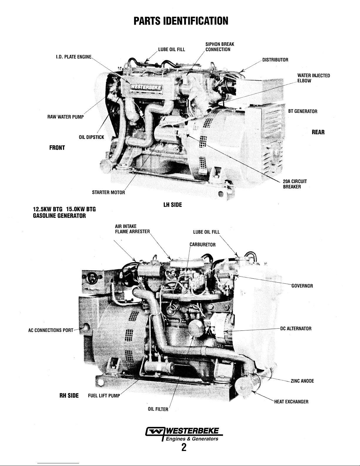
PARTS
IDENTIFICATION
LUBE
OIL
FILL
SIPHON
BREAK
CONNECTION
DISTRIBUTOR
BT
20A
CIRCUIT
BREAKER
WATER
INJECTED
ELBOW
GENERATOR
REAR
12.5KW
BTG
GASOLINE
AC
CONNECTIONS
15.0KW
BTG
GENERATOR
PORT
AIR
INTAKE
FLAME
LH
SIDE
LUBE
OIL
FILL
RH
SIDE
OIL
FILTER
Engines & Generators
2
HEAT
EXCHANGER
ANODE
Page 11

FRONT
HEAT
EXCHANGER
PARTS
OIL
DIPSTICK
IDENTIFICATION
SIPHON
BREAK
CONNECTION
WATER
INJECTED
DISTRIBUTOR
GENERATOR
COMPONENTS
.20A
CIRCUIT
BREAKER
REAR
AC
CONNECTIONS
PORT
STARTER
MOTOR
LH
SIDE
AIR
INTAKE
FLAME
ARRESTER
8,5KWBTG
GASOLINE
OIL
GENERATOR
FILL
ANODE
FUEL
LIFT
PUMP
LUBE
OIL
DRAIN
RHSIDE
Page 12

INTRODUCTION
ORDERING
Whenever
generator
include a complete
part
needed
insist
or
generic
cations
NOTES,
As
this
maintenance
tor,
critical
CAUTIONS,
NOTE:
A
observed,
tile
A
followed,
NOTE:
.
by
WESfERBEKE.
the
engine
SPARES
Certain
your
SUGGESTED
as
proper
the
way.
spares
on-board
PARTS
replacement
and
engine
(see
upon
WESTERBEKE
parts
are
as
original equipment
CAUTIONS
manual
An
takes
schedules,
information
and
operating
CAUTION:
can
engine
01
WARNING:
can
A carbon
room.
AND
spare parts will be
WESTERBEKE
SPARE
fuel
and
WESTERBEKE
and
accessories
inventory of
parts
are
needed,
model
and
serial
part
description
the
separately
frequently
AND
you
through
and
will be
WARNINGS.
procedure
Prot:edures,
teSUif
in
the
generator.
Procedures,
result
in
personal
monoxide
Affix
this
and
furnished
packaged
not
made
WARNINGS
the
troubleshooting
highlighted
An
explanation
essential
which
damage
·
which
injury
warning
decal
decal
in a visable
ACCESSORIES
needed
to
generator
PARTS).
oil
filter
the
brochure
or
Often
can
be
difficult
will
provide
to
proper
WESTERBEKE
engine
assist
always
numbers.
part
number
Parts
Catalog).
parts
because
to
the
same
operating
of your
by
NOTES,
to
note.
U
not
strictly
01
destruction
if
not
01loss
has
support
and
when
even
simple
to
obtain
you
with a suggested
you
in
provide
In
addition,
for
each
will
specifi-
procedures,
genera-
follows:
of
properly
of
life.
been
provided
location
maintain
cruising
items
along
preparing
parts.
the
Also
fit
in
(see
such
an
PROTECnNG
Care
at
the
have
resulted
many
thousands
manufacturer
installed
operated
buyer/owner-operator.
NOTE:
Six
•
Proper
• An
ejJicient
an anti-siphon break to prevent water from entering the
engine.
•
Changing
ing hours.
Proper
•
nents according
manuol.
•
Use
clean,
•
Winterize
Recommissioning" section in this manual.
UNDERSTANDING
The
gasoline
ways
similar
are
verticle
overhead
a
solid-state
camshaft-driven.
lubrication
which
is
generator's
that is
required
important
ventilation,
cooling
CARBON MONOXIDE DETECTOR
YOUR
factory
in a
cannot
in
the
vessel
and
serviced
important
engine
weU-designed
the engine oil
maintenance
filtered
your engine according
engine
to a gasoline
in-line,
GamShaft
distributor
system,
thennostatically-controlled.
engine
factors
maintenance
system
INVESTMENT
during
assembly
WES1ERBEKE
of hours of
and
to
and
which
The
and a fresh
requires
of a
to
and
dependable
control
how
or
the
manner
in
the
field.
steps
to
ensure
generator installation
exhaust system that
and
oil
of
all engine
the maintenance schedule in
unleaiJed
THE
driving
the
which
engine
gasoline
the
the
fueL
GASOLINE
an
AC
automobile
engine's
is
chain-driven.
is
horizontally
incorporates
water-cooled
the
same
automobile
generator's
of
the
fuel
generator
and
thorough
generator
or
where
in
This
long
filters every 100
capable
service.
the
generator
which
the
is
up
to
generator
and
and
generator
to
the "Lay-up and
GENERATOR
generator
cylinder
preventive
longevity
system,
backend.
engine.
The
a
To
a large
engine.
is
The
head
mounted
pressure
engine
are
ignition
testing
However
unit
the
olignment.
includes
in
many
cylinders
has
engine
degree,
maintenance
The
proper
of
the
is
is
life:
operat-
compo•
this
an
utilizes
and
type
block
the
most
system,
WESTERBEKE
monoxide
quarters. Carbon
ean
be
deadly.
The presence
exhaust
system,
or
If
Ventilate
locate the
Engines & Generators
leak
from
from
a neighboring
the dectector
4
highly
recommends
detector in the vessels living and sleeping
monoxide even in small amounts,
of
carbon
monoxide
from
the
main
engfu.e
the
the
area,
source
exhaust
signals
of
discharge location on the
vessel.
the presence
move
into a fresh air location and
the
carbon
mounting a carbon
indicates a possible
or generator, it's
of
carbon
monoxide
and arrest it.
monoxide.
exhaust
vessel
Page 13

FUEL,
ENGINE
OIL
AND
ENGINE
COOLANT
GASOLINE
A
CAUTION:
rating
of
harm
to
your
Care
Of
The
Use
only
clean fuel! The clearance of the
your
fuel
iqjection pump is very critical; invisible dirt
particles which might pass through the
these
finely
and
keep
it clean. The best fuel
unsatisfactory
facilities.
engine's
advisable:
Purchase a
Install
metal bowl type filter/water separator
and
ENGINE
Use a heavy duty
Specificati~
eilgine
break~in
change
SCHEDULE in this
To
daily
and
tile
engine.
OIL
on
and filter after the
operation.
intervalS
Only
use
unleaded
89
or
higher.
engine
Fuel
finished
by
assure that the fuel going into the
use
well~known
regularly service a
Section
'as
Leaded
and
fuel
violate
your
Supply
parts. It is important
can
be
careless handling or improper
is
clean
and
pure,
the
brand
of
fuel.
good,
Coast
engine
on
as
called for in the
of
this manual.
initial-
50 hours
Then
follow the olland filter
specified in MAINTENANCE
manual.
fuel
with
will
cause
warranty.
components
fllter
can damage
to
buy
rendered
following
Guard
between
~the
of
an
octane
serious
clean
storage
tank
for your
practice
approved
the
fuel
in
fuel,
tank
is
ENGINE
WESTERBEKB
50%
that
The
to
the
cooling circuit
antifreeze that
that
term
The
poured into
NOTE:
ontij'ree~
A proper
engine coolant to temperatures
COOLANT
A coolant
The
coolant
without
the
COOLANT
recommends a mixture
distilled
can
antifreeze perfonns double
run at proper temperatures by transferring heat
engine
keep
protection.
water and antifreeze should
purpose
cooling
water.
corrode
Use
internal
to
the
coolant. It also
from
contains
the
antifreeze
the
cooling
the
new
that is now
50/50
mixture
environmentally-friendly~
RECOVERY
recovery
expansion
the
tank
of
this
and contraction
loss
of coolant and
system.
Distilled water is
engine
surfaces.
duty.
lubricates
rust and
corrosion.
supplemental
chemically
circuit
available.
as
recommended
of
be
TANK
kit
is
supplied with
recovery
tank
without
of
free
It
allows
Use a
cooling
balanced,
premixed
will protect
-40"F
is
to
allow
during
engine
introducing air
50%
antifreeze
from
the
chemicals
the
engine
away
and
protects
good
quality
additives
crucial
before
long
lasting~
each
generator.
for
engine
operation,
from
the
{SCAs)
to
long
being
the
into
and
Westerbeke
disapprove the use
oils
are
using conveirtional
be
as listed in the MAINTENANCE SCHEDULE
section
oils
are
NOTE: The
previous statements regarding synthetic on.
Corporation does not approve
of
synthetic oils.
used, engine break-in ... ust
oil.
on
change
of
this
manua1
used.
information above supersedes all
and
not
extended
or
If
~thetic
be
perfor.tn!'d
~tervals
__
must
if
sYnthetic
Engines & Generators
5
Page 14

CONTROL
PANELS
DESCRIPTION
The
generator mounted control_panelis equipped
ON switch
switch (red).
The ON switch provides power to the start circuit
switch by-passes
until the oil pressure reaches
The
cranks
switch
The
switch must
The panel also has two
• A 15 amp slow bluw fuse protects
•An
any optional
REMOTE
An optional remote start/stop panel is available
controlling the generator from a remote location.
This panel
previously described. Also included is a green
which glows once the engine/generator
rpm's. The purpose
release the START switch. It is also
engine/generator
(black),
START switch energizes the start solenoid/starter which
the
engine.
is
depressed and held at the
STOP
switch
8 amp fuse protects the
START/STOP
has
a START switch(white)
the
protective
This
switch
will
turn off the engine/generator,
be
depressed until the stop sequence
fuses
rembte
start/stop
the same ON, START, and STOP
of
the LED is
is running. ·
oil
pressure
5 - I 0 psi.
will
not operate
same
to protect
engine
or
instrument
PANR
to
time.
the
the
start
operating
(OPTIONAL)
has
alert the
an
indication that the
and
a
shutdown
unless
DC
circUit:
circuit.
circuit
panel.
for
LED
reached
operator
with
an
STOP
This
switch
the on
.This
is
complete.
·
Ond
functions
light
600
to
..
REMOTE
An
includes
DC charging voltmeter, operating
switches.
INSTRUMENT
optiol)al
remote instrument
a water temperature gauge,
·
REMOTE
The
installed
an
oil pressure
located
installed in the thermostat housing
is
adjace~~
on
the-thi:eads
each
wiring
The
is
for the water temperature
between
removed. Refer
DIAGRAM
NOTE:
installers
standards
INSTRUMENT
remote instrument
on
the engine
gauge
on
the engine.
to the oil pressure switch.
of
sender
are
tied off
harD.ess),
blue wire
iS
tenninal board connections
in this
When
installing
responsibility
33
CFR
both
PANEL
PANEL
panel
block,
sender.
The
water temperature sender is
senders.
next
(OPTIONAL)
panel
is
available
oil
pressure
hourmeter,
and
INSTALLAnON
has two sending units to
a water
Plugged ports for each
to
temperature
and
the oil pressure sender
Use
sealing
Electrical connections
the senders location ( in
· · · . . .
.'for
the
oil
to.
the.
manual.
part
j»:essure
sender.
REMOTE
the
optional
to
comply
183.
sender
and.
If
there
is a jumper
T-1
and
T-2,
INSTRUMENT
rembte
panels,
with
the
U.S.
which
gauge,
start/stop
be
sender
are
compound
for
the tan
it
should
WIRING
it
is
Coast
Guard
and
the
wire
be
the
. Engines & Generators
6
Page 15

OPERATING
INSTRUCTIONS
PRESTART
Before starting your generator for the first time
longed layoff, check the following items:
a Check the engine oil level:
the full mark on the dipstick.
INSPECTION
add
or
after a pro-
oil to maintain the level at
a Check the fuel supply and examine the fuel filter/separator
bowls for contaminants.
a Check the
and battery cable connections.
DC
electrical system. Inspect wire connections
a Check the coolant level in both the plastic recovery tank
and at the manifold.
NOTE:
After the
the
engine's cooling
recovery
the
cooling system
after
the
tank will be
replace
Before subsequent
manifold should
tank
the purged
may
tank.
engine
drawn
need
initial
Open
has
be
to
be
running
system
will
the
air bleed petcock
is
purged
of
cooled,
into
air.
operation
topped
the
filled
the
engine's
off,
to
of
the
generator,
be
purged
air.
After shutdown and
coolant
of
the
and
the
cooling
generator,
the
MAX
level.
from
coolant
to
the
to
ensure
the
system
the
the
air
coolant
that
recovery
to
engine's
recovery
.
in
a Check load leads for correct connections as specified in
the wiring diagrams.
a Examine the air inlet and outlet for air flow obstructions.
a Be sure no other generator or utility power
the load lines.
is
connected to
a Be sure that in power systems with a neutral line that the
neutral is properly grounded (or ungrounded) as the system
requires, and that generator neutral is properly connected
to the load neutral.
or open neutral can supply the wrong line-to-neutral volt-
age on unbalanced loads.
A
CAUTION:
recommended
motors,
to
speed
be
switched
and,
precaution
pated
operation
cold
engine
In single phase systems
When
starting
that all
In
will
from
AC
OFF
cold
climates,
prevent
of
the
stalling.
until
damage
AC
the
loads,
especially
the
engine
starts
caused
machinery
an
incomplete
generator,
large
has
to
warm
by
unanticl·
and
will
it
Is
come
up
up.
This
prevent
a
STARTING
A
for a
·
ventilating
fumes
1. Depress
this
2. Depress
starts,
the
NOTE:
the
oil pressure shutdown circuit allowing
pressure to rise enough
maintain the ignition circuit
3.
Release
Once
ator
ature
If
an
gauges for
NOTE:
This condition should smooth out
and when the generator loads are applied
THE
GENERATOR
WARNING:
minimum
from
the
primes
the
release
ON
switch
Keeping
the
The
engine
and
allow
(130°-150°
optional instrument panel is installed, monitor the
normal
Some unstable running may occur
Ventilate
of
five
blowers
the
generator
ON
switch and hold it down (5-15 seconds),
carburetor. Continue to depress ON.
START (white), when the generator
the
START
a few seconds longer.
the
ON
ON
switch.
is running apply a light load to the gener-
the engine
F/
55°-56°C) before applying heavy loads.
readings.
the
generator
minutes
remove
prior
any
explosive
compartment
switch. Continue to engage
switch,
depressed by-passes
to
close the switch and
to
warm up to operating temper-
as
to
starting.
the engine warms
compartment
The
gasoline
and
bilges.
the
oil
in
a cold
engine.
up
A
CAUTION:
the
engine
exhaust
pump
cooling
enter
with
is
pumping
system
the
manifold
from
happening
through~hull
co«ecting
Engine
damage
wa«antable
in
mind.
STOPPING
1. Remove the
generator to run for an added 3 to 5 minutes (this stabilizes
its
qperating temperature).
2.
Depress the
When the generator stops, release the
3.
NOTE:
In
an
the stop
panel.
switch,
Prolonged
starting
raw
can
water.
raw
during
enginets
once
the
cylinders
the
exhaust
by
closing
shutoff~
cause
draining
of
resulting
Issue:
the
THE
GENERATOR
AC
loads from the generator and allow the
STOP
(red) switch.
emergency,
remove
cranking
result
This
water
through
cranking.
by
system
the
the
excessive
from
in
may
way
raw
the
raw
intervals
filling
happen
the
This
of
fills.
water
exhaust
water
owner/operator
if
the
generator will not
the 8 amp
fuse
the
because
raw
raw
water
the
exhaust
Prevent
supply
muffler,
engine
entry
should
STOP
in
the
without
engine
water
can
this
cranking.
Is
not
keep
switch.
stop
control
the
and·
a
this
using
Engines & Generators
7
Page 16

DESCRIPTION
Although your engine
test
hour of
assembly procedures
operated properly, a break-in
life of
operated and serviced
Breaking-in a
piston
and
scored,
break
Your
conditioning operation
to
maximize the perlormance
Perlorm
following:
Start the engine according
section. Run the engine
water
reach
AFTER
Once the generator
tion
between
operations
your
engine
new
rings
to
smoky
operation
which
is
-in
period.
new
engine requires approximately 50 hours of initial
this
conditioning
pump,
oil pressure, battery
its
full
rated speed
START-UP
and
then encourage a
20% and
has
at
were
is
dependent
during
engine basically
the cylinder
indicate
caused
by
to
while
has
been
60%
of
experienced a minimum of one
the
followed
break
carefully,
are
fast
GENERATOR
factory
to
make
sure accurate
and
that the engine
time
is
required. The service
upon
how
the engine
its
initial hours of
involves
walls.
Excessive oil consumption
that
the cylinder walls are
overloading
in
each
and
service life
keeping
to
the
STARTING
checking that all systems
charging)·
signs
of
an
started,
check for proper opera-
warm-up.
full
load for
the
use.
seating the
the
engine during
moving part
of
the engine.
in
mind the
PROCEDURE
are
functioning.
overload.
Run
the generator
first
10
in
hours.
BREAK·IN
is
the
order
PROCEDURE
the
After
load
can
periodically
Avoid
overload
smoky
exhaust
Monitor
it within the generators'
1800
rpm
control of the generators
drawn
current
NOTE:
Be
current
amperage
amperage.
GENERATOR
Once
the generator
(raw
governor adjustments
the engine's break-in
(see
period
ENGINE
also
be required in conjunction
ment
(see
first
10
hours of
be increased
vary
the
current being
to
produce
aware
drawn
draw
See
to
the
load.
at all
times.
with
reduced output
rating.
60
from
the
generator.
of
motor
required for
can be 3
GENERATOR
ADJUSTMENTS
has
been
required
period
ENGINE
ADJUSTMENTS. A
GENERATOR
SPEED
the
generators
the
full-load
An
overload
drawn
Since
hertz,
or
engine
break
starting
starting
to 5 times
INFORMATION
placed
for
(first
(HERIZ)ADJUSTMENTunder
no-load
with
INFORMATION).
operation,
rated
output,
is
signaled
voltage
from
at
loads
motors.
normal
engine speed (hertz) during
50
and
frequency.
the
generator
the
generator operates
1500
to
produce
-in
is
governed
and
the
high
This
starting
running
in
in
operation,
hours)
voltage
the
engine's speed adjust-
there
or
after
adjustment
the
then
this
by
a
and
50
hertz,
by
the
manual.
may
this
keep
at
be
may
THE
CHECK
Follow
• Check that all generator circuit breakers (power panel)
•
•
• Check the oil
• Check the coolant
• Check your
• Check the starting
• Check the drive belt
CHECK WITH
• Check for abnormal noise
•
LIST
this
checklist each
the off position before
Record
the hourmeter
to the maintenance
Visually
blow-back sounds.
Confirm
When
When the engine
When
inspect the engine
exhaust
the
engine
the engine
level
fuel
THE
schedule).
(dipstick).
level
supply.
batteries
ENGINE
smoke:
is
cold
is
is
day
before starting your
starting.
reading
for
warm -almost
overloaded -some
in
your log (engine hours
for
fuel,
oil,
in
the
coolant recovery tank.
(weekly).
wear
and
proper tension
RUNNING.
such
as
knocking, vibration
-White
Smoke.
Smokeless.
or water leaks.
Black
DAILY
generator.
(weekly).
Smoke.
are
relate
an:tf
ROUTINE
NOTE:
Some unstable
This
condition should
is
reached and loads
in
A
CAUTION:
periods
generator.
of
time
running
abate
are
Do
not
without
may
as
normal
applied.
operate
.a
load
occur in a cold
operating
the
generator
being
placed
engine.
temperature
for
long
on
the
8
Page 17

ALARMS
AND
CIRCUIT
BREAKER
SAFETY
The engine
switches.
without
~ng
TROUBLESHOOTING
The
switches:
High
An exhaust temperatllre switch is located on the exhaust
elbow.
the
sensor indicate an excessive exhaust temperature
quate.supply
This
resets
HIGH
SHUTDOWN
is
protected
Should a shutdown
SWITCHES
by
three
occur,
finding and correcting the cause.
Engine
starts,
runs
and
then
section
of this
following
Exhaust
DC
switch opens at
at
1s
a description of these
Temperature
Normally closed, this switch will
voltage (shutting off
of
raw water
approximately
··~
'
SWitch
the
causes
260-270"F
225'"F
(107°C).
EXHAUST
automatic
shutdown
do not attempt to restart
Refer
to
the
shuts
down
in
the
ENGINE
manual.
autoJIUltic
open
engine) should
high exhaust temperatures).
(127-132°C).
shutdown
and interrupt
the
switch's
(an inade-
This switch
TEMPERATURE.
SWITCH
MOUNTED
EXHAUS(ELBOW
AT
THE
·head-
LOW
OIL
PRESSURE
Allow
oil
pressure
gallery.
sure.
(0.4-
.
Engine
Tlie
manual
draw
wiring
event
breaker
and
fault,
This
switch's sensor
Should
generator's engine is protected
or electrical overload
repair
the
kg/cD).
engine
the
sourc;e
2
Breaker
0.7
Circuit
reset circuit breaker (20
or
the generator will-shut
interrupts
reset the breaker and restart the generator.
ALARM
!llarm
switch
engine's oil pressure
),
this
switch
wiring-
will cause
the
DC
circuiUf
of
the
SWITCH
is
located off
monitors
will
activate a pulsating alann.
amps
anywtrere
the
down
because
problem.
the
the engine's
fall
to
5-10
by
an
engine
DC).
Excessive current
in
the
inst:rum.ent
breaker
this
After repairing
the
shoUld
to
opened
occur,
engine's oil
oil
pres-
psi
'DIL
AlARM
DIL
PRESSURE
mol!Jlted
panel
trip.
•
In
this
check
the
PRESSURE
SWITCH
SWITCH
COOLAIT.TEMPERATURE
A coolant temperature
housing.
coolant's 6peta.ting
210"F
This switch will activate a continuous
(9~C).
switch·
temperature
SWITCH
is
located
reaches
. .
THERMOSTAT
ALARM
SWITCH
on
tbe>thermostat
alarm
aPproximately
ASSEMBLY
if
the
OVEilSPUD
BOARD
High
RPM
Shutdown
An overspeed
generators
engine's speed
correcting the
tarily
DIAGRAMS
NOTE: When troubleshooting a possible faulty
switch. For test purposes to by-pass the switch.
Move
DO NOT purposely by-pass a faulty switch so
to
be
create a potential
engine
depressing the
in this
connection
able
to
operate the generator. This could
SWitch
switch
in
by
grounding
reaches
problem,
stop
manual.
T4
safetY
the
DC
circuit
out
2175
rpm(approximately).
this switch
switch.
onto
hazard.
Refer
TS.
shuts off
the
ignition
can
be reset by
to
the
WIRJNG
TERMINAL
th~
system
if
After
momeq'-
as
the
l"'fAriWESTERBEKE
Engines:& Generators
9
Page 18

A
WARNING:
running.
use
the
correct
servicing
NOTE:
Many
more
difficult and
MAINTENANCE
Never
Wear
any
of
of
the
attempt
the
proper
tools
for
the
engine's
following maintenance jobs
may
require
to
safety
equipment
each
job.
BC
electrical
the
expert knowledge
perform
Disconnect
SCHEDULE
any
service
such
the
equipment.
are
as
goggles
battery
simple
of
a service
while
the
and
terminals
but others
mechanic.
engine
gloves,
are
is
and
when
SCHEDULED
MAINTENANCE
Fuel
Supply
Fuel/Water
Engine
Coolant
Drive
Visual
Spark
Generator
Fuel
Starting
(and
Engine
Re-torque
*Adjust
Clearances
Air
Exhaust
Engine
Inlet
Separator
Oil
Level
Level
Belts
Inspection
Plugs
(if
Filter
(Lift
Batteries
House
Batteries)
Oil
Cylinder
the
Valve
Screen
(Flame
System
Hoses
Fuel
Filter
applicable)
Pump)
of
Engine
Head
Arrester)
CHECK
EACH
DAY
D
D
D
D
D
weekly
D
D
weekly
HOURS
OF
OPERATION
50
100
250
500
750
1000 1250
NOTE:
Please
keep
engine
surface
clean.
and
oil
will
inhibit
the
engine's
ability
to
remain
cool.
D
D
D D
D D
D 0 0 D D D D
D
D D D D D
D
D D D D D D D
D D D
D D D
D
D D D
0 D
D D
D
D D 0 D
D
0 0
Dirt
0
EXPLANATION
Unleaded
higher.
Check
if
Oil
dipstick.
Check
Add
Inspect
and
Check
and
Check
Check
Check
with
(if
Inspect
Every
and
excessive
Initial
change
retorque
Initial
Clean
Initial
for
exhaust
on
Check
spongy.
gasoline
for
water
and
necessary).
level
should
indicate
at
recovery
coolant
if
needed.
for
proper
adjust
if
needed.
for
fuel,
oil
electrical
applicable)
make
leaks.
inside
Hose
Replace every 250 operating hours.
connections.
for
loose
gap;
inspect
that
AC
connections
no
chafing -see
for
for
fuel
50
operating
sure
corrosion.
engine
oil & filter
both
every
at
50
adjustment
at
50
hours,
check
at
Check
elbow
passages;
that
all
should
be
Check
leaks.
connections
hrs.,
50
for
connections
and
OF
SCHEDULED
MAINTENANCE
with
octane
rating
dirt
in
fuel
(drain/replace
between
tank;
if
empty,
tension
(3/8"
to
Check
belt
edges
and
water
leaks.
Keep
bolts & nuts
belt
tension.
for
burning
and
are
clean
GENERATOR
addition
information.
Check
wire
hours
check
electrolyte
are
very
change
at
100
hours.
them
every
500
at
50
hrs.,
then
every
then
every
100
hrs.,
then
every
siphon
brake
operation.
carbon
and/or
clean
andreplace
are
tight.
hard & tight.
tighten
Replace
all
hose
of
FULL
check
1/2"
Inspect
corrosion.
and
INFORMATION
connections.
tight.
50
hours.
hours.
250
corrosion
clamps.
89
or
filter
and
LOW
at
manifold.
deflection)
for
wear.
wiring
tight.
secure
levels
Clean
hrs.,
then
500
hrs.
hrs.
Inspect
Check
buildup
as
necessary.
if
soft
or
on
off
the
continued
Engines & Generatnrs
10
Page 19

NOTE:
Use
engine
hours
MAINTENANCE
the
engine
by
running
hourmeter
time.
gauge
to
SCHEDULE
log
your
engine
hours
or
record
your
SCHEDULED
MAINTENANCE
Heat
Exchanger
Raw
Water
Pump
Coolant
System
*Starter
Distributor
*Engine
*Exhaust
Motor
Cylinder
Compression
Valve
Clearance
Elbow
and
CHECK
EACH
DAY
50
0
0
HOURS
OF
OPERATION
100
250
500
0 0 0 0 0
0
0 0
0 0
0
0
0 0
0
750
1000
1250
0
0
EXPLANATION
MAINTENANCE
Clean
or
replace
anode.
cap
and
clean
out
debris.
for
professional
Remove
for
wear,
Lubricate
Drain,
flush,
appropriate
Check
solenoid
and
lubricate.
pinion
drive.
Check
ignition
distributor
Incorrect
performance.
timing
Test
exhaust
casting
WARNING: A defective
carbon
cleaning
the
pump
replace
both
when
and
antifreeze
and
Clean
timing.
cap
and
valve
clearance
Check
and
adjust
elbow
is
corroded
monoxide
cover
if
needed.
re-assembling.
refill
cooling
motor
and
rotor.
compression
valve
for
or
leakage.
OF
SCHEDULED
Open
heat
exchanger
remove
every 1 000
and
pressure
and
inspect
Also
replace
system
mix.
for
corrosion.
lubricate
Check
will
clearances.
casting
deteriorated.
exhaust
the
condition
result
in
pressure
integrity.
elbow
testing.
the
impeller
the
with
starter
of
poor
Replace
can
end
hours
gasket
Remove
motor
engine
and
if
cause
Carburetor
Screen
*WESTERBEKE
Filter
recommends
this
service
0
be
performed
by
an
0 0 0
0
authorized
mechanic.
Clean
at
first
50
hours
and
every
250
hours.
Engines & Generators
11
Page 20

GASOUNE
Use
-,.leaded
follow
companionways
ventilate
NOTE:
The
detector/alarm
GASOLINfJWATER
A primary
installed between the
water and other contamirulnts from the
be
carried
Most
instaliers
the installation
that contaminants in the fuel can
These
through'') to meet
bowls have drain valves to use
impurities,
89
.octane
U.S.
Coast
Guard regulations,
to
prevent fumes
after
fueling,
engine
torrtpartment should
properly
SEPARATOR
:fuel
filter of the water separating type must be
fuel·
to
the
fuel
syStem
~lude
~kage
gas
~e filiers must have
0
U;S.
or higher
installed
tank
,on
a type of
as
they
Coa8t
Guard
gasoline.
from
and:
and
the engine to
the
engine.
filter/water~
are
well
cause.
metal
when
FUEL
When
fueling,
clare.
off all
hatcQes
enteij11g
have
working,
AfiJ
bowls
requirements.
checking for water and
a
gasqline
FILTER
fuel
before they
aware
(not
·the
· · ·
of
and
boat,
and·
.
fuine
remove
can
with
the
problems
..
see-
Tbe'metai·
SYSTEM
The
pump
filter
also
clean
off the magnet [the magnet
from
the
fuel].
base hex nut with a
~ggasket
AwARN•G:
CDIIIIBI:fioJJS
Malee
Sllre
fuel
system
.FUR
UFT
should
be cleaned
The
pump base
wrench.
Fuel
is a fire
proper
t:DIRptments.
bazanl
relltilation
PUMP
can
When
leakage
and
every
250
removes
be
removed
reaSsembling,
at the fuel
should
exiSts
WJ.flnerel
operating
metal
by
twisting
rephice
PIIIIIP
be
t:DITBI:ted.
simnt:ing
hoi!rS;
particles
the
the
or its
#14PURPLE
PRESTART
·
BIJ7TON
GASOUNE/WATER
SEPERATOR & RlTER
·C~
The carburetor is a single barrel
by
metalic choke. Refer to
for more information. ·
RJa
UFI'
PUMP
Periodically check the fuel connections
and make sure that no leakage is present and that
are tight and
pump's mounting bolts should be clean and well
the
mo~ting
The start sequence energizes
the
pump operates, it creates
ticking is heard, check for
Also checkthat the ground wire is properly connected
ground.
NOTE: At initial start-up or when re-commissioning the engine,
it maybe necessary to prime the engine's fuel system.
depress and hold the
electric fuel pump which will pump fuel through the engine's
fuel system and
4-6 seconds then proceed to start the engine.
secure.
The DC ground connection at
bolt to ensure proper
ON switch. This will activate the engine's
fill
the carburetor's fuel bowl. Do this for
downdraft
CARBURETOR
to
pump
the
fuel
lift pump
an
audible ticking
12
volts
at
the
type
with
an
electric
ADJUSI'MENTS .
and out of
operation.
pump
the
the
fittings
one
of the
secured
as
the
piston
sound.
If
connections.
to
To
pump
by
in
no
do this
Periodically check
pump
and
make sure that no leakage
fittings
are tight
one of the pump's mounting bolts
secured.l:zy
operations.
the
fuel connections
and
secure. The DC
the mounting bolt to ensure proper
is
ground
should
to
and
present
connection
be clean
out of
and
that
and
pump
the
the
at
well
IW'IWESIERBEKE
f
Engirtf!S
&_Generators
12
Page 21

COOLING
SYSTEM
DESCRIPTION
Westerbeke marine engines are designed and equipped for
fresh water cooling. Heat produced in the engine by
tion and friction
circulates throughout the engine.
coolant cools the engine block,
the engine
fresh water coolant to raw water
exchanger, similar in function
water
flows
fresh water coolant
ferred to the fresh water coolant is conducted through the
tube walls
exhaust system where finally it
other words, the engine is cooled by fresh water coolant, this
coolant is cooled
transferred heat overboard through the exhaust system. The
fresh water coolant and raw water circuits are independent of
each
other.
allows the cooling water passages
. harmful deposits.
FRESH
NOTE:
WATER
Refer to
recommended
fresh
water
Fresh water coolant is pumped through the engine
lating pump, absorbing heat from the engine. The coolant
then passes through the thermostat into the manifold, to the
heat exchanger where it
block via the suction side
engine
is
the
closed thermostat (although some coolant
bypassed around the thermostat to prevent the exhaust
fold from overheating). As the engine warms up, the thermostat gradually opens, allowing
coolant
cooling system.
to
Coolant
A coolant recovery tank allows for engine coolant expansion
and contraction during engine operation, without
cant loss of coolant
ing system. This tank should
engine manifold level and should be easily accessible.
NOTE:
Periodically
sure
cap.
good
condition
closes
tightly.
is
transferred
oil.
The heat is transferred externally from the
through the tubes of the heat exchanger while
flows
to
the
raw
water which is then pumped into the
by
raw water, and the raw water carries
Using
only
COOUNG
the
ENGINE
antifreeze
to
fresh water coolant which
11ris
circulating fresh water
its internal moving parts, and
by
means
of
to
an
automotive·radiator.
around
tl_le
tubes; engine
is
discharged overboard. In
fresh water coolant within the engine
to
stay clean and free
CIRCUIT
COOLANT
and water
section for
mixture
to
coolant.
is cooled, and returned to the engine
of
the circulating pump. When the
started cold, external coolant
full
flow
unrestricted
Recovery
and
check
Ensure
that
and
check that the
Carry a spare
to
the
Tank
without introducing air into the cool-
be
the
condition
the
upper
cap.
flow
is prevented
flow
of
the engine's
e~temal
located at or above the
and
vacuum
portion of the
of
the
lower rubber
valve
combus-
a.
heat
heat
the
be
used
by
flow
is
any
manifold
seals
opens
trans-
from
as
a circu-
mani-
signifi-
pres-
are
and
Raw
the
the
by
in
CHANGING
The engine's coolant must be changed according to the
MAINTENANCE
become contaminated,
A
oritit:al; a substantiallllllllber
trat:ed
Drain the engine coolant by loosening the drain plug
engine block and opening the
the system with fresh
NOTE:
be
used
A
Wear
Refilling
After replacing the engine block drain plug, close the heat
exchanger's coolant petcock. Then run the engine at idle and
slowly pour clean, premixed coolant into the manifold.
NOTE:
When a steady
the
petcock
Monitor
the manifold
sure
cap.
Remove the cap
coolant mix
the cap.
flow
into the recovery tank.
After checking for leaks, stop the engine and allow it
Coolant should
engine cools
needed.
TO
COOLANT
RECOVERY
COOLANT
SCHEDULE.
it
CAUTION:
bat:k
The
drain
to
help
WARNING:
pmtet:tive
Open
the
Run
Clean
TANK
Proper
to
DDD/ing
water,
petcock
drain
engine
Beware
gloves.
the
Coolant
the air-bleed petcock
flow
of
coolant
and fill
the
sy$tem
coolant in the manifold and add
to the filler neck and install the manifold pres-
on
the coolant recovery tank and
to
halfway between
the engine and observe the coolant expansion
draw
back into the cooling system
down.
Add coolant
up
any spilled coolant.
If
the coolant is allowed
can lead to overheating problems.
cooling
sysflllll
on
syst11111
of
maintenanoe
engine
failures
DDIIDSion.
ma,tifold pressure cap. Flush
then start the refill process.
the
heat
exchanger
coolant.
of
the
bot
engine
on
the
heat
appears
until
at
the
the
manifold
LOW
and MAX and replace
to
the recovery tank
COOLANT
EXPANSION
t:an
should
coolant.
exchanger.
petcock,
remains
as
needed. Fill
fill
as
be
on
also
close
with
to
the
if
to
is
the
full.
cool.
l"ffiN'lWESTERBEICE
l Engines & Generators
PRESSURE
/
CAP
Page 22

COOLING
HEAT
EXCHANGER
Cool
raw
water
flows
through the inner
exchanger.
the
which
The engine coolant
engine
The engine coolant
qther;
harmful deposits
Heat
After approximately
and
motive
exchanger).
NOTE:
As the engine coolant passes
heat of
the
internal engine is conducted
is
then
pumped
and
the circuit repeats itself.
this
keeps
Exchanger
pressure test the engine's heat
radiator shop should be able
Operating
into
the
exhaust
(now
cooled)
and
raw
water are independent of each
the
engine's water
found
in
raw
water.
Service
1000
hours of operation, remove,
in
silty and/or tropical
that a heat exchanger cleaning be peifonned
every
1000 hours.
THERMOSTAT
A thermostat controls
continuously flows
the
engine is first started the closed thermostat prevents
from
coolant
thermostat to prevent
ing).
As the engine
The thermostat is accessible and can be checked, cleaned,
replaced easily. Carry a spare thermostat
Replacing
To
avoid spilling
manifold level [REFER TO CHANGING COOLANTj.
Remove the cap
housing
gasket, apply a thin
gasket before pressing it into
cap screws. Replace
engine and check for
no
leaks at
flowing (some coolant
the
as
-shown.
the
the
coolant temperature
through
warms
the closed cooling circuit.
the
exhaust
up,
the thermostat gradually
Thermostat
coolant,
screws
thermostat housing.
drain the coolant
and disassemble the thermostat
When
installing
coat
of sealant on
pi~.
the
coolant in the manifold.
normal
temperatures and that there are
tubes
around
system
flows
back
passages
exchanger.
to
clean
waters
is
by-passed
manifold
and
the
new
both
Do
not over-tighten
of the heat
these tubes
to
the
raw
water
and
discharged.
though the
clean
from
the
clean
(A local
and test the
more
as
from over-heat-
gasket.
down
thermostat
sides of the
auto-
may
require
often
the coolant
When
around the
opens.
below
and
Run
the
heat
then
or
the
the
SYSTEM
ZINC
ANODE
A zinc anode (or pencil)
circuit within
anode
in
the
of electrolysis
condition
the
anode cleaned or replaced,
should
NOTE:
and
vessel
HEAT
If
the
wj:rich
loosening the anode
hex
boss
zinc
is in poor condition,
flakes
exchanger and clean the
have
a spare heat exchanger
one
becomes damaged
Replace the gasket (refer
exchanger end gasket part
install
the
heat
is
to
sacrifice itself
raw
water cooling
on
other
of
the zinc
be
carried onboard.
Electrolyiis is
location,
EXCHANGER
D-RING
zinc
anodes need
the zinc anode
from
possibly
within the
a new zinc
exchanger.
anode.
is
located
exchanger.
to
electrolysis
circuit,
components
anode
should be checked
the
result
not
that
of
END
GASKET
replacement,
is
threaded with a
with
another
tearing
there
Remove
inside
end
when
removing the end
to
your
number),
in
the
raw
water cooling
The purpose of
action
thereby reducing
of the
system.
as
required. Spare
of
each particular
the
engine.
hold
the
wrench
wrench. This
off the exchanger
are
probably a lot of
the
end
of
of all zinc
gasket in case
engine model's
debris.
0-ring and
the
zinc
taking place
the
effects
The
monthly
and
anodes
installf:ztion
hex
boss
into
while
prevents
shell.
If the
zinc
the
heat
Always
the
present
cover.
l1eat
cover,
and
,·
the
THERMOSTAT
ASSEMBLY
COOLANT
TEMPERATURE
ALARM
SWITCH
14
NOTE:
The
not
require
insulate
housing
threads
the zinc from the
preventing
sealant
of
the
Sealant
electrolysis
zinc
should
metal
anodes
are pipe
not
be use4
of
the heat exchanger
action on
NEW
the
ZINC
ANODES
threads
as
it
zinc.
REPLACE
and
may
CLEAN
&
do
OFF
REUSE
Page 23

RAW
WATER
NOTE:
Always install the strainer at or below
the
strainer
A
clean
engine's cooling
strainer
in
the
glass
Perform
operation:
1.
Close the
2.
Remove
3.
Clean
4.
Replace
5.
Reassemble
6.
Open
7.
Run
NOTE:
Also follow
aground.
If
the
engine
normal
may
raw
reading,
have
water through the cooling system
INTAKE
will
always
raw
water intake strainer
system.
when
making your periodic engine
should be
the
following maintenance after
raw
and
clean the strainer
the
glass.
the
sealing washer if
and
the
seacock.
the
engine and check for
temperatUre
the
been caught
STRAINER
be
self-priming.
Include a visual inspection of
clear.
water seacock.
install the
the
above procedure after having
gapge ever
cause
may
up
in
the strainer, slowing
COOLING
the
waterline
is a vital
filter.
necessary.
strainer.
leaks~
be that silt, leaves or grass
component of the
check.
every
100
shows
a
highe~
this
The water
hours
run
than
the
flo~
so
of
hard
of
SYSTEM
RAW
WATER
The
raw
non-ferrous housing
has
flexible blades
within
the impeller housing, producing
On
no account should this
always
be
(an
impeller
when
lubricant
operation.
are
cautioned
up.
The
broken
or tom impeller blades.
SCHEDULE.
NOTE:
Should a failure occur with
(seals
and
chase
a new pump and rebuild
Changing
Close the raw water intake valve.
and,
with
impeller out of the
Move
the
push
the
bling,
apply a
gasket.
Open the raw water intake valve.
Run
the
check for water discharge at
flow
indicates
PUMP
water
pump
is
a self-priming, rotary
and
a Neoprene
which
wipe against a curved
a spare impeller and impeller cover gasket
kit).
Raw
water pump impeller
(raw
water)
Such failures are
to
make
sure raw water
raw
water pump should
bearings), it
the
the
aid of
blades
impeller into
thin
engine
the
may
Raw
Water
two
small screwdrivers, carefully
pump.
Install the
to
conform
the
pump's housing.
coating of lubricant
and
check for leaks
pump
has
impeller.
the
JlUr!JP_
be run
is
not present during
not
warrantable,
flow
be
inspected periodically
See
MAINTENANCE
the
pump
be
more
cost efficient
the
original pump
Pump
to
the
not primed itself
Remove
the
curved
stem
Impeller
new
to
around
tube.
pump
The
impeller
cam
pumping
d:rJ.
There
failures
engine
and
operators
is
present at
:SO
internal
to
as a spare.
the
pump
impeller
cam
the impeller
plate
When
assem-
the
pump.
Absence
properly.
and
with
plate
action.
should
aboard
occur
start-
parts
pur-
cover
pry
gasket.
and
and
Also
of
water
a
for
the
·
RAW
WATER
TYPICAL
INTAKE
[OWNER
INSTALLED)
STRAINER
15·
A
CAUTION:
impellei;
the
they
cooling
exchanger
It
any
must
circuit.
of
be
located
They
the
vanes
often
have
to
prevent
can
be
broken
blockage
found
in
off
the
the
in
heat
Page 24
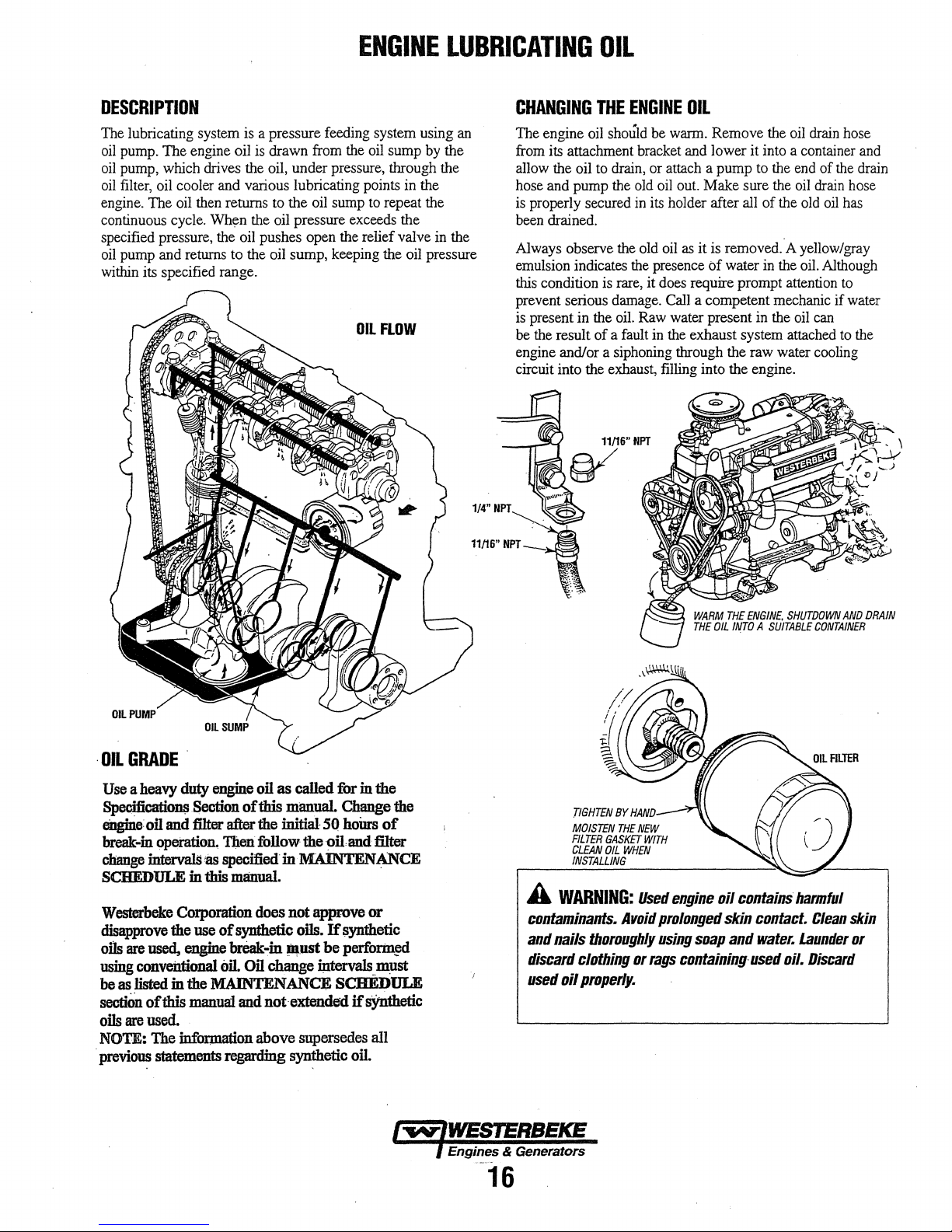
ENGINE
LUBRICATING
OIL
DESCRIPTION
The lubricating system is a pressure feeding system using an
oil
pump. The engine oil is drawn from the oil sump by the
oil
pump, which drives the oil, under pressure, through the
oil
filter, oil cooler and various lubricating points in the
engine. The oil then returns
continuous cycle. When the oil pressure exceeds the
specified pressure, the oil pushes open the relief valve in the
oil pump and returns to the oil sump, keeping the oil pressure
within its specified range.
to the oil sump
to
OIL
repeat the
FLOW
CHANGING
The engine oil should be warm. Remove the oil drain hose
from its attachment bracket and lower it into a container and
allow the oil
hose and pump the old oil out. Make sure the
is properly secured in its holder after all of the old
been drained.
Always observe the old oil
emulsion indicates the presence
this condition is rare, it does require prompt attention
prevent serious damage. Call a competent mechanic if water
is present in the oil. Raw water present in the oil can
be the result
engine and/or a siphoning through the raw water cooling
circuit into the exhaust, filling into the engine.
THE
ENGINE
to
drain, or attach a pump to the end of the drain
of
a fault
OIL
oil
as
it is removed. A yellow/gray
of
water
in
the oil. Although
in
the exhaust system attached
drain hose
oil
has
to
to
the
OIL
PUMP
·OIL
GRADE
Use a heavy
Specificatio~
eiJgine
break-in
change
SCHEDULE in this
Westerbeke
disapprove
oils
are
using
be
as
listed in the MAINTENANCE SCHEDULE
section
oils
are
NOTE:
previous
duty
engine
oil as called for in the
Section
oll
and
filter after the initial 50
operation.
intervals as specified in
of
this manual Change the
'f4en follow the
MAINTENANCE
manual.
Corporation does not approve or
the use
used,
conveiltional
of
this
used.
The
statements regarding synthetic
of
synthetic oils.
engine
oil.
manual
break-in
and
~ust
Oil
change intervals.must
not·extended ifsjtnthetic
information above supersedes all
oil
If
be perforin!ld
honrs
of
and filter
synthetic
oil.
TIGHTEN
MOISTEN
FILTER
GASKET
CLEAN
OIL
INSTALLING
A
WARNING:
contaminants.
and
nails
thoroughly
discard
used
clothing or
oil
properly.
BY
HAND
THE
NEW
WHEN
Used
Avoid
WITH
engine
prolonged
using
rags
containing
oil
soap
contains
skin
contact.
and
water.
used
harmful
Clean
Launder
oil.
Discard
skin
or
16
Page 25
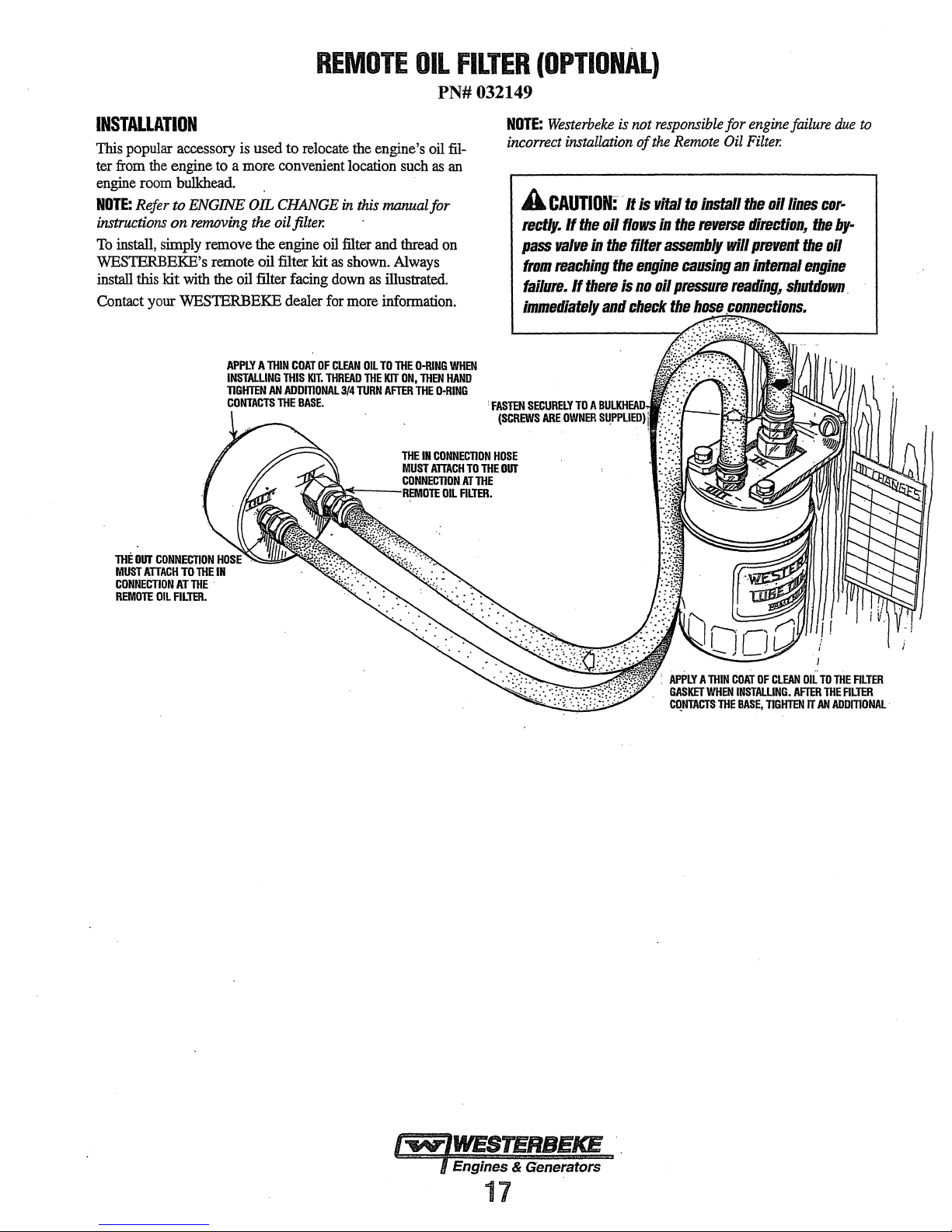
INSTALLATION
This
popular accessory
ter
from
the
engine
engine
room
bulkhead.
NOTE:
Refer to ENGINE OIL
instructions
To
install, simply remove the engine
on
removing
WESTERBEKE's remote oil filter kit
install
this kit
with
Contact your WESTERBEKE dealer
is
used to
to
a more convenient location
relocate
CHANGE
the oil
filter.
the oil filter facing
REMOTE
the
in
this
oil
filter and thread
as
shown.
down
as
for
more
OIL
engine's
manual for
information.
oil
such
as
Always
illustrated.
FILTER
PN#032149
NOTE:
filan
on
incorrect
A
rectly.
pass
from
failure.
immediately
(OPTIONAL)
Westerbeke
installation
CAUTION:
If
valve
reaching
If
the
in
there
is
oil
the
the
and
not
of
·It
is
flows
filter
engine
is
no
check
responsible
the
Remote
vital
to
In
the
reverse
assembly
causing
oil
pressure
the
hose
for
engine
Oil
Filter.
Install
the
oil
direction~
will
prevent
an
intemal
reading,
coniJletJ!tlolirs.
failure
due
lines
cor-
the
by-
the
oil
engine
shutdown.
to
THE
OUT
CONNECTION
MUST
ATTACH
OIL
TO
AT
ALTER.
CONNECTION
REMOTE
THE
THE
IN
APPLY A THIN
INSTALLING
TIGHTEN
CONTACTS
THIS
AN
ADDmONAL3/4
THE
COAT
KIT.
BASE.
OF
CLEAN
THREAD
OIL
TO
THE
TURN
THE
KIT
ON,
AFTER
D-RING
THEN
HAND
THE
D-RING
WHEN
APPLY A THIN
GASKET
WHEN
CQNTACTS
THE
COAT
OF
CLEAN
INSTALLING.
BASE,
AFTER
TIGHTEN
I
OIL
TO
THE
THE
IT
AN
AODmONAL
ALTER
FILTER
·
Engines & Generators
17
Page 26

CARBUREtOR
ADJUSTMENTS
CARBURETOR
The
carburetor
cleanable
The
electric
opens
the choke automatically
remains
generator
load
on
Air
ScreeD/Flame
The
air
releasing
of
operation,
screen
in
is a single
metal
screen
choke
uses
running.
the
is
started, is
generator.
Some
on
(The
Arrester
screen/flame
the hold-down
every 100
a water soluble cleaner such
arrester
barrel,
down-draft
air
intake
filter/spark
a 12-volt heating
once
the engine
hunting
hours
choke,
choke
can
clamp.
will occur
and is
is
factory
easily
Clean after
from
then
element
when
rumring
be
removed
the
on.
as
GUNK.
type
with
arrester.
which
starts
the
without
set).
first
Clean
a
and
by
50
hours
the air
Carburetor
Clean
then.clean
the
screen
there
Idle Mixture
a
Ajustment
Screw the jet
out
Note:
induce a sooty
Yz
this
are
to 1
An
Filter
Screen
filte~
element after the
~d
mspect
every 250
1f
necessary.
no
leaks.
Jet
is
performed with the generator not operating.
in
turn.
idle
mixture
exhaust
Tighten
slowly until you
jet adjusted
discharge
first
50
hours
operating
the
plug
feel
too
at
hours.
and
it seat. Then back it
far off
engine
start-up
of
make
its
seat
operation,
Replace
certain
can
and
shut-
down.
FROM
FUEL
FILTER
SEE
ELECTRIC
IN
THIS
MANUAL
ENGINE
ADJUSTMENTS
UNDER
IDLE
MIXTURE
JET
Engines & Generators
·fa
·
Page 27

NOTE:
WESTERBEKE
ments
be
below
is
ENGI.NE
recommends
performed
provided
by a competent
to
assist the
ADJUSTMENTS
that
the
engine
mechanic.
following
mechanic.
·
engine
The
information
adjust-
ELECTRIC
The electric choke
CHOKE
uses a 12
volt heating element
opens the choke automatically when
The choke is
the
choke
rotating the cover clockwise
counterclockwise
set at the factory
. temperature. The
commissioning
engine is operating
on
the underside of
HIGH
Cheek the ignition
compartment
adjusted
by
loosening
to
for
choke
for
the
in.
TENSION
CORDS
wires
heat
can
with
the
engine off
the three cover-securing
to
LEAN the
RICH
the
choke. The
an
average of
may
need readjustment at engine
ambient temperature of
The
choke reference
the
choke
cover.
(IGNmON
every 500 operating
deteriorate
Check the resistance of each wire.
because the wire connection inside
separated or the insulator
the wires from the spark plugs,
cap, then pull
THE
RESISTANCE
the
cap
VALUE
may
off the spark
IS
410
OHM
be
grasp
PER
TESTING
RESISTANCE
the
engine
and
70"F
(21
WIRES)
the
wires.
Do
not pull
the
cap
damaged.
and
plug.
INCH.
starts.
cooled.
screws
choke
and
choke
°C)
room
the
mark
hours
on
may
become
When
twist the
which
Adjust
and
is initially
area the
is
·located
as
engine
the
wire
removing
molded
IGNITION
1.
Attach a timing light
front crankshaft
the
Each timing mark represents
2.
· Start the engine
operating
3. Using the timing
ccim:kshaft
ignition timing scale embossed
cover.
distributor
TIMING
8.5.~¥!
12.5Kw
15.0Kw
ENGINE
Iiit
compression, warm
Remove the spark
(screws into a
Crank the
ignition
maximum reading
Measure
nMING
timing
scale embossed
and
temperature:
light,
pulley with'theproper
Do this
SPECIACATIONS
13°
13"
18"
by
body.
BTDC
BTOC
BTOC
loosening
Refer
±
±
±
COMPRESSION
becomes
necessary
pl!J.g
engine
(close
coil. Allow
the
compression·
the
plugs
hole)
the
and
to
the
#1
spark plug
on
groove
the
and
engine's
2°.
warm
the
engine
align
the
timing
timing
on
the
and
slowly
to
the timing specifications:
t•
al1800
rpm
1"
al1800
rpm
1"
al1800
rpm
TEST
to
check the
engine and shut it
and install a
with a gauge.
off the
compression
~ord.
pressure for
raw
engines
water)
gauge
the
front
to
engine's
compression
each
that the pressure differential for each cylinder
· specifications.
and
timing
cover.
its
normal
groove
mark
rotating
cylinder
down.
and
to
reach a
cylinder.
is
mark
mark
in
the
on
the
front
the
adapter
unplug
within
the
on
front
the
Ensure
the
COMPRESSION
LIMIT
OF
If
a cylinder's
the limit, add a small
PRESSURE
DIFFERENCE
plug hole and repeat
pressure, the
damaged.
piston
If
the added
pressure suspect poor
wear.
Reinstall
raw
water
thru
/'"WV"IWESTERBEKE
) Engines
!It
·Generators
19
AT
300
UMIT
AT
300
BETWEEN
compression
CYliNDERS
or pressure
amount
the
test.
ring and/or cylinder
oil
does
valve
the
plugs,
ignition
seacock.
RPM
RPM
of engine
If
the
I}Ot
contact,
170
128
2.8
differential
oil
oil
causes
increase
valve
wireS,
LBJIN'
[12.0
LB/IN'
[9.0
LBJIN'
[2.0
through
an
wall
may
compression
seizure,
and
coil.
Kg-cnr]
Kg·cm2]
Kg·cm2]
is
below
the spark
increase
be
worn
or
valve
Open the
of
or
Page 28

NOTE:
ments
be
below
is
ENGINE
WESTERBEKE
performed
provided
to
by
assist
ADJUSTMENTS
recommends
a
competent
the
that
engine
mechanic.
the
following
mechanic.
engine
The
information
adjust-
VALVE
After
valve
NOTE:
engines
CLEARANCE
the
initial break-in period (approximately 50
clearances should
Retorque
valves
the
cylinder head
(see
TORQUING
BOLTS).
1.
Remove
2.
Position the No.I piston at
compression
valves.
crankshaft
valves.
CLEARANCES:
the rocker cover and gasket
stroke
While
facing
360"
clockwise and adjust the remaining
VALVE
CAM
SIDE
ADJUSTMENT
be
adjusted.
bolts
before
THE
CYUNDER
Top
Dead
Center ('IDC) of its
and adjust the
the
front of
SIDE
INTAKE
EXHAUST
INTAKE
EXHAUST
#1
and
the
engine, rotate
0.010
in
.0012
in
0.007
in
0.009
in
hours),
adjusting
HEAD
#3
exhaust
(0.25mm)
(0.30mm)
(0.18mm)
(0.23mm)
the
the
the
CYLINDER
BOLTPAnERN
TORQUING
After the initial break-in period (approximately 50 hours),
cylinder head
Loosen the cylinder head bolts one half turn in
shown.
the sequence shown
rocker cover stud
HEAD
THE
CRINDER
bolts
should be re-torques. ·
(The engine should
beiow.
securely.
1
HEAD
BOLTS
be
cold). Then tighten the
One
bolt at a time. Tighten
the
order
bolts
the
8
the
in
3.
Replace the
ROCKER
rocker
COVER
VALVE
CLEARANCE
cover and rocker cover
TIGHTENING
TORQUE:
2.6-4.0
VALVE
CLEARANCE
CYLINDER
5&-59
OIL
The
by
the
normal
· 60 psi (2.8 and 4.2
NOTE:
reading
an
oil
Ft-lb
gasket.
(4.11-6.0
Kg-m)
readings
engine
TESTING
To
test the
install a mechanical oil pressure
warming
and read
Oil
Pressure
Sender
1-..IWESTERBEKE
· l Engines & Generators
HEAD
BOLTS
Ft-lb
(7.8-8.2
TIGHTENING
Kg-m)
TORQUE:
PRESSURE
6
engine's
oil
pressure,
oil pressure gauge on the instrument panel. During
operation,
A newly
up
pressure
will
and
up
the
and
Switch
the
started.
to
60
psi
reading
vary
the
TP.l'M.·
OIL
PRESSURE
oil
pressure, remove the oil pressure sender,
the
engine, set
oil pressure
35.0
lblin'
Torgue
during
operation,
oil pressure will range between 40
kglcm2).
cold
engine
can
(4.2
kglcrrf). A warmed
as
low
as
35
depending
(3.8
upon
the
gauge.
kg/em')
9
-13
gauge
engine
or
more
ft-lb
the
· ·
(1.2
is
have
an oil
engine
psi (25
kg/em:).
temperature
in
it's
speed
at
at
1800
rpm.
·1.8 m ·kg).
indicated
place.
1800
and
pressure
can
have
These
of
the
then
After
rpm
20
Page 29

ENGINE
ADJUSTMENTS
SPARK
The spark plugs should be cleaned and regapped after the
first
thereafter
SPARK
SPARK
NOTE:
the spark
of
PLUGS
50
hour break-in period, then inspected every 250 hours
and
replaced as needed.
A
WARNING:
the
engine
removing
PLUG
GAP:
PLUG
TORQUE:
Loctite Anti-Seize applied to the threaded
plugs
the spark
Do
not
is
hot.
Allow
remove
the
the
engine
spark
to
cool
plugs
before
them.
0.031- ±
will retard corrosion, making future removal
plugs
10
-151b·ft
easier.
0.0002
(1.5
in.
(0.8-0.05
-2.31
mm).
kg-m).
while
ponion
INSPECTING
THE
SPARK
PLUGS
of
DRIVE
The drive belts must be properly tensioned. Excessive drive
belt tension
service life
and engine coolant pump. A
on the
temperatures and the failure
1.
BELT
ADJUSTMENT
can
cause rapid
of
the bearing and the alternator, raw water pump,
belt
can cause belt slipping, resulting
To adjust the alternator and the engine coolant belts,
loosen the alternator mounting bolts and pivot
alternator as needed. Retighten the bolts.
2.
To
adjust the raw water pump belt, loosen the mounting
bolts and slide the pump up and
the
Retighten
NOTE:
When the belts are loose, inspect
frayed edges,
3. The drive belts are properly adjusted
no less than 3/8 inch (lOmm) and
(12mm) as the belt
midpoint between the two pulleys
the belt.
4. Operate the engine for about 5 minutes, then shut down
the engine and recheck the belts tension.
NOTE:
Maintain a 22 lb pressure to the belt's outer face
proper
ried on board.
bolts.
and
belt
operation. Spare belts should always be car-
wear
ofthe
belts and reduce the
slack
belt
or
the presence
in
high operating
of
the
same
components.
down
as needed.
for
wear, cracks and
replace if necessary.
if
it can be deflected
no
more than 1/2 inch
is
depressed with the thumb at the
on
the longest span
the
of
oil
for
of
CHECK
FOR
CARBON
BURNING
AND
A
WARNING:
drive
belt's
tension
Never
while
attempt
the
engine
to
check
or
is
in
operation.
adjust
a
21
Page 30

ENGINE
NOTE:
WESTERBEKE recommends that the following
engine adjustments be
mechanic. The information below is provided to assist the
ADJUSTMENTS
peiformed
by a competent engine
ENGINE
SPEED
(HERTZ)
ADJUSTMENT
Governor
The belt-driven, mechanically operated governor maintains
the engine's rpm under various load conditions. Engine speed
determines
Governor
Operate the generator to bring the unit up to operating tem-
perature before adjusting the governor.
NOTE:
adjust the linkage
before proceeding with the adjustment.
There are three adjusting points on the governor (see illustration).
1.
Increase/Decrease Speed Adjustment. This adjusting bolt
sets the no-load speed
the governor and the throttle lever should be
hold the throttle
ball joint
position (when the engine .is not running). Make sure this
linkage moves freely and that the ball joint connectors are
properly lubricated. Use graphite
Disconnect the ball joint and apply graphite lube to the
inside
2. Hunting/Regulation Adjustment.
engine speed between no-load and full-load
adjust this eye bolt to draw the spring closer to the lever
hub. The increase/decrease speed bolt
adjusted as well.
If
move the spring away from the lever hub (check speed
adjustment).
Bumper
3.
a no-load surge
into the governor so far that it
the hertz and voltage output
of
the generator.
Adjustments
If
the governor is severely
at
no-load to obtain a safe output voltage
just
slightly closed; about the width
at
the linkage arms
of
the joint.
the governor surges under load, adjust this eye bolt to
Screw Adjustment. This screw is used to remove
ONLY. NEVER
out
of
adjustment, manually
of
the engine. The linkage between
adjusted to
end
towards the closed
lube for this purpose.
If
the variation in
is
too
great,
may
need to be
tum
the bumper screw
incre~es
the no-load speed.
of
the
Governor
1. Periodically lubricate the linkage arm attaching points at
2. Governor oil capacity - 3 ounces
3. Change the governor oil every
4. Periodically adjust the governor belt tension (see DRIVE
SPEED
Maintenance
the governor arm and throttle lever. Use a graphite lubricant or equivalent.
NOTE:
Free movement
proper governor/throttle operation.
NOTE:
Do not overfill the governor.
To change the oil, remove the governor from the engine,
remove the oil fill and the fill level plug, and drain all the
oil. Reinstall on the engine and
engine oil. Replace the plugs.
BELTS ADJUSTMENT). Since belts stretch slightly, this
stretching will, to some degree, affect the govenor's
action.
LINKAGE
HUNTING
REGULATION
ADJUSTMENT
ADJUSTMENT
of
this linkage arm is important
10/30 engine oil.
250 hours
till with 3 ounces
of
operation.
of
10/30
for
22
NOTE:
Synthetic oil is recommended
for use
in the governor.
Page 31

DESCRIPTION
The
charging system consists
regulator,
cuit
the
regulator
back of
an
engine DC wiring harness, a mounted DC cir-
breaker
use
and a battery with connecting cables. Because of
of integrated circuits (IC's), the electronic voltage
is
very
compact and
the
alternator.
ALTERNATOR
of
an
alternator
is
mounted internally or
with
a voltage
on
the
TESTING
1.
Start
the Engine.
2.
After a
few
minutes
tery
voltage at the battery terminals using a multi-meter
set
on
DC volts.
The
voltage should be increasing toward
the
alternator
of
running measure
is working. Tum
to
Step 4 .
rnm
the
14
starting
volts.
If
bat-
it
is,
TROUBLESHOOnNG
A
WARNING:
hot.
Do
not
This
troubleshooting section is
exists with the charging circuit or with the
determined that the alternator or voltage
best to
have
The
alternator charging circuit charges the
the
service
battery.
battery selector switch
late the batteries so the service battery
with
the service battery.
ing
battery
service
battery
Testing
A
that
sheaves
A
DC
applfcatiiJIIS.
Isolate
before
made
the
WARNING:
everyone
and
WARNING:
and
AC
DC
performing
without
A failed
touch
a qualified technician check it out
An
but
not the service battery,
charging circuit and not with
altemator
until
the
alternator
isolator with a
is
usually mounted
If
the alternator
to
determine
can
has
n:gulator
diode,
is
not discharged along
is
the
Alternator
Before
is
clear
belts
during
MOLT/METERS
circuits
and
are
Always
AC
converters
DC
pmper
starting
of
moving
often
disconnect
testing.
knowledge
the
parts!
test
pmcedures.
AND
mixed
and
No
of
engine
DC
together
shore
shut
AC
tests
AC
bectJIIIe
alternator.
starting
in
charging
problem
Keep
CIRCUITS:
power
down
circuits.
very
csoled
dswn.
if
a problem
is
bad,
battery and
a solenoid, or a
the
circuit
the start-
is
in the
the
alternator.
make
away
in
marine
cords,
generators
should
be
If
it is
it
to
iso-
certain
ffDIII
is
0
MULTIMETER
COM
'
TESTING
BATIERY • ALTERNATOR
(ENGINE
3.
If
the starting battery voltage remains around
after the engine
problem exists with the alternator
a.
Thm
off the engine. Inspect all wiring and
Ensure that the battery terminals and the engine
connections are tight and clean.
A
CAUTION:
charging
switch
when
b.
If
a battery selector switch is
ensure that it is
c.
Tum
on
d. Check
condition the reading should
THE
STARTING
RUNNING)
is
started and run for a
To
avoid
damage
circuit,
the ignition switch, but
the
never
shut
the
engine
on
battery voltage.
is
the correct setting.
running!
If
or
to
off
the
in
the charging
do
your battery
be
12
12
few
minutes, a
the charging
connections.
the
battery
engine
battery
not start the
is
in
to
13
volts.
volts
circuit.
ground
.
circuit,
engine.
good
TESTING
BATTERY
EN_GINE
THE
VOLTAGE
NOT
I...,.,.IWESTERBEICE
l Engines & Generators
23
RUNNING
-::-
GROUND
~--tMULTIMETER
Page 32

7.
Now
check
the
voltage between the alternator output
minal
(B+)
and
ground.
at
the
alternator
isolator is
1.0
exists
Check all the connections - look for
charging circuit.
in
the circuit the alternator voltage will be
volts
lower.
If
in
the circuit between the alternator
If
the circuit is
will
be
the
same
neither of the above
DC
good,
as
the
battery,
is
true,
and
an
opening in
MULTIMETER
ELECTRICAL
ter-
the
voltage
or if
an
.5
-
a problem
the
battery.
the
· ( 14.0]
SYSTEM
Checking
Check the voltage of
have a voltage between
running.
charging circuit. Troubleshoot the service battery charging
circuit
by
isolator, battery switch, and
the
If
not,
checking
Service
the
there
is
the
Battery
service battery. 1bis battery should
13 and 14 volts when the engine
a problem in the service battery
wiring and connections,
the
battery itself.
the
solenoid,
is
G
COM
.,
TESTING
BATTERY/ALTERNATOR
(ENGINE
8. Start the engine again. Check the voltage between
alternator output and ground.
The voltage reading for a properly operating alternator.
should be between
is
over- or under-charging, have it repaired at a reliable
service facility.
NOTE:
voltmeter
at the
tery
present
fo.r
breaks and poor connections.
THE
STARTING
RUNNING)
Before removing
to
ensure that
EXC terminal if
voltage at
the
at
the
EXC terminal, trace the
13.5 and 14.5 volts.
the
alternator for
12
volts DC excitation is present
the
previous test showed only
B output terminal.
ae::::=---'
If
your alternator
repair;
If
12
volts
wiring
and look
is
ENGINE
GROUND
the
use
a
bat-
not
MULTIMETER
GROUND
A
CAUTION:
diodes,
when
do
performing
To
not
use a high
avoid
tests
damaging
voltage
on
the
alternator
SERVICE
TESTING
BATTERY
THE
{ENGINE
the
alternator
tester
(i.e. a megger}
charging
BATTERY
SERVICE
RUNNING)
circuit.
.
12
VOLT
Dt;
The engine
shown
diagrams
elec1Jical
A
circuit,
the
however,
engine's
bas
on
the-
wiring diagrams that
when·
system. ·
CAUTION:
never
engine
is
to
avoid
electrical circuit.
BATTERY
The
nritlimlllll
the engine's
Cranking
12
Amps
CONTROL
a 12 volt DC ·electrical control circuit that is
troubleshooting or
To
shut
mnning.
:rel:P]Jlll).ended
volt DC control circuit is
(CCA).
CIRCUIT
avoid
damage
off
the
engine
Shut
electrical
follow.
Refer to these
when
servicing the DC
to
the
battery
battery
off
the
engine
shorts
when
capacity of the battery used in
600-
charging
switch
battery
working
900
while
switch,
on
the
Cold.
Battery
Re\dew the manufacturer's recommendations and then
establish a systematic maintenance schedule for your
engine's
0 Monitor your voltmeter
0 Check the electrolyte level and specific gravity
0 Use only distilled water
0 Make
0
A
cause
protective
Care
starting batteries and house batteries.
for
proper chargipg
engine operation.
hydrometer.
to
bring electrolytes to a proper
level.
certain
that battery cable connections
tight to the batteiy posts (and
Keep
your batteries clean and
WARNING:
severe
burns
gear.
SUlfuric
on
skin
acid
and
to
in
your engine).
free
of
corrosion.
lead
batteries
damage
clothing.
during
with
are
clean
can
a ·
and
Wear
24
Page 33

ENGINE
The
following troubleshooting tables are based upon certain
engine problem indicators and the most likely causes
problems.
When
troubleshooting indicates an electrical problem, see the
ELECTRICAL SYSTEM WIRING DIAGRAM, as these may
reveal other possible causes
listed below.
of
the problem which are not
TROUBLESHOOTING
of
the
NOTE:
The engines control system (electrical system) is
protected by a 8 Ampere manual fuse located on the control
panel.
The generator has an
panel which should be in the
troubleshooting.
AC
circuit breaker
off
position when peiforming
at
the control
PROBLEM
Engine
crank.
Engine
but
then
down.
Engine
but
does
up
to
speed.
does
starts,
shuts
starts,
not
not
runs
runs
come
PROBABLE
1.
Voltage
drop
at
starter
terminal.
2.
Engine
circuit
breaker
3.
8
amp
fuse/holder
4.
Battery
is
low
or
5.
Loose
battery
connections.
Faulty
wire
6.
7.
Faulty
8.
Faulty
9.
Faulty
10.
Raw
1.
Faulty
(oil
temperature).
2.
Faulty
Dirty
3.
4.
Low oil level in sump.
5.
Faulty fuel pump.
1.
Governor out
2.
Governor linkage binding.
connection.
start
switch.
starter
starter
water
filled
shutdown
pressure,
overspeed
fuel/water
relay.
solenoid.
coolant
3. Faulty fuel pump.
4.
Restricted fuel supply.
5.
Throttle plate binding.
6.
AC
generator issues.
7.
Air intake restricted.
8. Exhaust restricted.
9.
Air in fuel system.
CAUSE
solenoid
has
is
faulty.
dead.
cylinders.
switch.
or
exhaust
switch.
separator
of
adjustment.
tripped.
filter.
PROBLEM
Engine
cranks
fails
to
start.
Engine
hunts.
Engine
misfires.
Engine
backfires.
.l
Engine Overheats
but
PROBABLE
1.
Out
of
fuel.
2.
Engine
is
Bad
ignition
3.
Faulty
4.
5.
6.
spark
Unplugged
Faulty
etectricalconnection.
1. Governor
CAUSE
flooded.
coil.
plug.
distributor
needs
2. Faulty governor.
3. Faulty fuel pump.
Generator overloaded.
4.
5.
Valves
need
adjustment.
1.
Poor
quality
fuel.
2.
Incorrect
3.
Dirty
4.
Cracked
Faulty
5.
Spark
6.
High
7.
Valve
8.
1.
Spark
Incorrect
2.
3.
Engine
4.
Dirty
5.
Cracked
6.
High
1.
Coolant
cooling
2.
Faulty
Belts
3.
Raw
4.
5.
Faulty
timing.
flame
arrester.
distributor
ignition
wires.
plugs
are
exhaust
back-pressure.
clearances
plug
wires
timing.
is
flooded.
flame
arrester.
distributor
exhaust
back-pressure.
loss.
Pressure
system.
raw
water
are
loose
or
water
pump
thermostat.
cap.
worn.
are
are
cap.
Refill.
pump
broken.
worn.
wire.
adjustment.
incorrect.
connected
test
impeller.
wrong.
25
Page 34

ENGINE
TROUBLESHOOTING
PROBLEM
Low
oil
pressure.
High
oil
pressure.
No
DC
charge
starting
battery.
Blue
exhaust
discharged
engine.
to
smoke
from
the
the
PROBABLE
1.
Low
oil
level.
Wrong
2.
3.
4.
5.
6.
7.
1.
2.
1.
2.
1.
2.
3.
4.
5.
SAE
Faulty
or
wrong
Relief
valve
Faulty
oil
Faulty
engine
Faulty
oil
Dirty
oil
or
engine.
Relief
valve
DC alternator connections.
Faulty
Lube
oil
is
·High
lube
Crankcase
Valves
are
incorrectly.
Piston
rings
or
unseated.Black
type
is
stuck.
pump.
bearings.
filter.
wrong
is
stuck.
DC
alternator.
diluted.
oil
level.
breather
worn
are
CAUSE
oil
type
SAE
or
adjusted
worn
exhaust
in
the
oil
filter.
type
hose
engine.
oil
in
is
clogged.
smoke
the
PROBLEM
Black
exhaust
discharged
engine.
Poor
performance
at
generator
smoke
from
speed.
the
1.
Dirty
flame
Idle
mixture
2.
Valves
3.
adjusted.
4.
Piston
Contaminates
1.
Faulty
2.
PROBABLE
are
rings
fuel
CAUSE
arrester.
jet
too
rich.
worn
or
incorrectry
are
worn
or
in
fuel
system.
pump/contaminated.
unseated.
26
Page 35

LAY-UP
&
RECOMMISSIONING
General
Many owners rely on their boatyards to prepare their craft,
including engines and generators, for lay-up during the off-
season or for long periods
accomplish lay-up preparation themselves.
The procedures which follow will allow you to perform your
own lay-up and recommissioning,
if
others do the procedures.
These procedures should provide protection for your
engine/generator during a lay-up and also help familiarize
you with its maintenance needs.
If you have any questions regarding lay-up procedures, call
your local servicing dealer. He will be more than willing
provide assistance.
Propeller
The transmission and propeller half couplings should always
be opened up and the bolts removed when the boat is hauled
out
of
storage in the cradle. The flexibility of the boat oftens puts a
severe strain
the boat is taken out or put in the water. In some cases, the
shaft has actually been bent by these strains. This does not
apply to small boats that are hauled out
not in use, unless they have been
period
Fresh
A 50-50 solution
mended for
This solution may require a higher concentration
depending on the area's winter climate. Check the solution to
make sure the antifreeze protection is adequate.
Should more antifreeze be needed, drain an appropriate amount
from the engine block and add a more concentrated mixture.
Operate the engine to ensure a complete circulation and mixture
system. Then recheck the antifreeze solution's strength.
Lubrication
With the engine warm, drain all the engine oil from the oil
sump. Remove and replace the oil filter and fill the sump
with new oil.
Shaft
the water or moved from land to water, and during
on
the propeller shaft or coupling
of
time.
Water
of
the antifreeze concentration throughout the cooling
Cooling
of
use
in the fresh water cooling system at all times.
System
Use
ENGINE LUBRICATING
"engine oil change".
Run the engine and check for proper oil pressure and make
sure there are
no
leaks.
of
inactivity. Others prefer to
or
will serve as a checklist
Coupling
[Propulsion
dry for a considerable
Engine]
or
of
the water when
both, while
Circuit
antifreeze and distilled water is recom-
of
antifreeze,
the correct grade
OIL
of
oil. Refer to the
pages in this manual for
to
Fuel
System
Top off your fuel tanks with unleaded gasoline
or higher. A fuel conditioner such as
stabilizer should be added. Change the element in your
gasoline/water separator and clean the metal bowl.
Re-install and make certain there are no leaks. Clean
up any spilled fuel.
Fuel
System
Top off your fuel tanks with No.2 diesel fuel. Fuel additives
such
as
control algae and condition the fuel. Care should be taken
that the additives used are compatible with the primary fuel
filter/water seperator used in the system. Change the element
in your primary fuel filter/water seperator,
has one, and clean the seperator sediment bowl.
Change the fuel filter elements on the engine and bleed the
fuel system, as needed. Start the engine and allow it to run
5 -
10
for
system. Check for any leaks that may have been created in
the fuel system during this servicing, correcting them
needed. Operating the engine for 5 - 10 minutes will help
allow movement
equipment
Raw
Water
Close the through-hull fitting. Remove the raw water intake
hose from the fitting.
gallon bucket
check the zinc anode found in the primary heat exchanger
the engine and clean
any zinc debis from inside the heat exchanger where the zinc
anode is located. Clean the raw water strainer.
Start the engine and allow the raw water pump to draw the
fresh water through the system. When the bucket is empty,
stop the engine and refill the bucket with an antifreeze
solution slightly stronger than needed for winter freeze
protection in your area.
Start the engine and allow all
through the raw water system.
the engine. This antifreeze mixture should protect the raw
water circuit from freezing during the winter lay-up,
as providing corrosion protection.
Remove the impeller from your raw water pump (some
antifreeze mixture will accompany it, so catch
Examine the impeller. Get a replacement,
cover gasket.
until recommissioning, but replace the cover and gasket.
[Gasoline]
of
STABIL
[
Diese~
BIOBOR and
minutes to make sure no air is left in the fuel
on
STABIL
of
the treated fuel through the injection
the engine.
Cooling
Place the end
of
clean fresh water. Before starting the engine,
or
Do
not replace the impeller (into the pump)
should be added at this time to
Circuit
of
replace it as required and also clean
of
this mixture to be drawn
Once the bucket is empty, stop
gasoline
if
the fuel system
this hose into a five
it
if
needed, and a
89
octane
as
as
well
in a bucket).
on
A
CAUTION:
oil
in
the
combustion
chemicals
internal
parts.
sump
deposits
which
Do
over
can
not
leave
the
lay-up
combine
reduce
the
engine's
period.
to
produce
the
life
Engine
harmful
of
your
old
engine
oil
and
engine's
Intake
Place a clean cloth, lightly soaked in lubricating oil, in the
opening
shove the cloth out
recommissioning, and
you may need assistance
note to remove the cloth prior to start-up. The thru-hull
exhaust port can be blocked in the same manner.
Manifold
of
the intake manifold to block the opening. Do
and
Thru-Hull
of
sight.
(If
an
attempt is made to start the engine,
of
the servicing dealer). Make a
Exhaust
it is not visable at
27
not
Page 36

I
I
I
bl
I
~
I
I
IZ
VDC
I
~-~
GlROJiO
~
.M.EAiill
~
0
=
.
.
ll
0
llARliE.
TO~LOCK
WIRING
DC
....
-------·
IWHEB
IE!!f
I
ll!iJl.ll
I
I I
I
r~·
I
I
0!._T!2H!Ll
L---
WIRING
DIAGRAM
Page 1 of2
~
~<;>
PISTf!IBUTQR
I
I
I
I
I
I
---b;
~
DIAGRAM
#37190
II
OIJI
•
....
.,
..
llAftlt
~
-.:::Jo
Ql~
fl!E~~Yl!E
.....----{
~
-.:::Jo
~
-=-=
~
~
•I
'"'1-
l':riJF:
JJ
w I I
~
I I
1
:
Q I L
:
PRESSYBE
llJill.l!.
~
; L - - - - -
.
:;
.
;
114
PUll
AITCRNATOR
·~
~c
ll
E~CJ
~
y
.
114
r
I'Uit
114
I'Uil
1
:
~P.!I~A..!:_I
,,.
; .
Q!.QJiE.
0
0
0
~
=
L I
EI
~
eut!e
.
~
~
.
~
114
R£0/PUit
~
112
RED
114
RED/PUR
114
TB3
U5708
U$111-G
TO
114
REMOTE
I.
REMOTE
flRH
RED/P'UR
135UI.
THIS
.,.
•14
llol
PUR
11
Sf
AU
JUMPER
I"AifELS.
REO
R£D
'WHEM
114
l'ELIRED
"'I
11·:1·:1·~1·~1~
FOR
CONNECT I ON$
AND
ft£MOTE I IISTRUMENT I"AMELS.
SEE
DRAWINGS
c
.
.·
r£t40V£
~
~
;
tU
TAll
~
.
l~~
~
~~----
~
~
t;;::
TB2
.,
.. REO/PUll
Ill
I'UII
tl4
PUR
114
TEL/JI£1)
Ill
RU/I'UII
IU
YELtltEO
112
REO
ll4,lllf:O/PUR
I
T:l
I"''IV'IWESTERBEKE
I Engines & Generators
IILIC
l
IU
r-
!--
~~~~~T~I
~~I
OIIERSf'EED
CltCin
®
28
.,
..
114
au:
lit
114
liZ
~
0
~
w
;
~·
RED/PUR
liED
YEL/IIE.D
Y£L/IED
tte
114
114 TEL/liED
SWITCH.
11'2 lt£D
0
'l:...
!ILK
...
PUR
~
114
PUll
....
~
ON .
.,
...
£~~
_.,...,
lQJf--JI•
'U"
YIAill
l.E.Me...
~
STOP
SWITCH
FUSE 2
15
ANP 5.8.
I
~
METER
START
SWITCH
FUSE I
8 ANP
I
;;
a!-
:
~
~H
r~-~0~~~~
T_l
·.
_TZ
OVERSP!lED
fOit!GIIfAL
SWITCH
OVEII$P£EI)
8
TS
$'11'1TCK
I!
I!
.
:
-H .
COIHifCTI0M$1
®
I
Page 37

WIRING
DC
:-+-:
12
v~>c
r
:
BATTERY
I
SWITCH
!
~
._
______________________
SCHEMATIC
WIRING
DIAGRAM
Page2of2
STARTER
SOLENOID
r--
~~~r-------~
L...
-·--·
#49167
#37190
-~
STARTER
TB3-4
15
I
F2
AMP~SB
EXHAUST
SWITCH
WATER
TEMP TEMP
SWITCH
~
~
0
~
:?
:?
~
0
w
~
~
OVERSPEED
(ORIGINAL
SWITCH
OVE.RSPEED
NOTI;S:
1.
WESTERBEKE
CWSJ'(E
COAST
NECESSARILY
ISOLATED FROM
IT
IS
TrlE
TION
COMPLY
2. THIS PRODUCT IS ?ROTECTED BY A MANUAL RESET CIRCUIT BREAKER LOCATED NEAR THE
STARTER
ANYWHERE
TRIP. IN THIS EVENT,
DISCONNECT
lliE
TWEEN ELECTRICAL DEVICES AND SEA WATER.
3.
AN
ON-OFF SWITCH
TERY IN AN EMERGENCY AND
CALLY DRAW
CYCLES SHOULD
175 AMPS AT 12 VOLTS
BE USED TO MAKE
4•
~E_I!C!E_5S.A.F!.IUiiUPPWED
- 'INSTRUMENT
GASOUNE
OF OPTIONAL REMOTE INSTRUMENT OR CONTROL PANELS COMPLY WITH U.S.
GUARD 33CFR-183. ACCESSORY INSTRUMENT AND CONTROL PANELS
SO
COMPLY AND ARE INTENDED
GASOUNE
F!ESPONSIBIUTY
OF
TriES_£ GENEP.ATORS, AND OPTIONALLY
wrrH
33CFR·183. . '
AND AS CLOSE AS POSSIBLE TO
IN
THE !JI!STRUMENT PANEL., WIRING OR ENGINE WILL CAUSE THE BREAKER TO
THE
INSTRUMENT PANEL., WIRING AND ENGINE ARE INSTAI.l.ED
THE FUEL. SUPPLY. THEREFORE, THE BUILDER/OWNER MUST
MUST
200TO
300 AMPS WHEN;¢j:t;e;NKING.
NOT
EXCEED 30 SECONDS. A SWITCH
WILL
THE
PANEL
®
~
0
~
~ ~
~
m
~
0
SWITCH
CONtfEC,TIO!lS)
MARINE GENERATORS AS SHIPPED FROM
SOURCES IN ACCORDANCE WITH 33CFR-183.410(B).
OF
lliE
BOAT MANUFACTURER TO ENSURE
ENGINE WILL SHUT DOWN BECAUSE THE OPEN BREAKER WILL
BE
INSTALLED
WHEN
NORMALLY SERVE
CIRCUIT.
WITH AN OPTIONAL
+
HOUR
METER
TO
BE INSTALLED ABOVE
lliEIR
THE
SOURCE
TO
DISCONNECT THE STARTER FROM
LEAVING THE BOAT. TWELVE VOLT STARTERS TYPI·
THE'
lliiS
OVERS
PEED
SWITCH
REMOTE INSTRUMENT PANELS
OF
CURRENT, EXCESSIVE DRAIN
DURATION
WITH
FUNCTION, BUT A SWITCH MUST NOT
'----------..._...,t--!IGHirio·.h--___.
[:t
lliE
lliE
BE
OIL
___
--------
DO
DECK AND
INSTALI.A-
SURE
lliE
TBZ-1
TBZ-2
lliE
FACTORY AND EX-
lliAT
TO
PREVENT CONTACT
OF
INDIVIDUAL CRANKING
A CONTINUOUS RATING OF
PRESS. · .
~E_t!_O~R-;;y~'l-
·
NOT
lliAT
BE·
BAT-
01 L
PRESS.
SWITCH
I I
L---
_I
~T.!_O~':._
._
./
_-
WATER
SEN.OER
_______
/-
__
f'j~
TEMP • ..._..,
~TJ.O~I._
TESTING
FOR
OVERSPEED SWITCH:
Original: Move
Current:
Move T5 onto T4.
.
_
A FAULTY
Tl
onto T2.
Engines & Generators
29
Page 38

a
a
.!!
~
c
..
-
-
VDC
GROUIO
TO
1/
0
BLOCK
I
I
I
BATTER~~lf
SWITCK
4'J
I
~
12
~~-
WIRING
DIAGRAM
DCWIRING DIAGRAM #044628 (TWO RELAYS)
Page 1
tnt
ORN
IU
BIUl
of2
ALTERNATOR
~
Ill
R£DIPUR
:
I
~~
: y
.
D
DISTRIBUTOR
OIL
PRESSURE
~IIIR£DIPUR
r
~JC-~
I
OIL
PRESSURE
I
liJiQll
L-----"!!~~1
5!A
QiQJ!.E.
-=" O
ALTERNATOR
35
AMP
tto
oaa
EXHAUST
~
~
~
TEMP
116
PRESTO! I IF
ISRDIPUR
112Rf'D
II&
tAN
IU
TB3
BRit
114
PUR
U4
f'UR
Ill
REO/PUR
Ill
\'Et.
YEL
Itt
REDIPI!'Il
114
BL•
......
t:J
112
TEL/RED
U2
Y[L/RE:t==ll.P
Ill
BLit
.....
GP
"'"l
0
SWITCH
FUSE 2
15
METER
SWITCH
STOP
ANP
HOUR
START
5.B.
<'
i
;;
·0
~
e
~
i
I!
~
51
AMP
AI
T
~
!!
D
~
.,
...
o
~__...:::
114
PUR
=c::J...lj)
~
U4
RtDIPUR
~~~~~~~~~~-~~~.
OVERSPEED
CIRCIJT
tr4
RED
Engines & Generators
30
FUSE 1
8 ANP
ON
SWITCH
OVERSPEED
SWITCH
t0li:1611Al OVE'ASP£[0
SWITCH.
CQNfti[Cl'IOlCSl
Page 39

NOTE:
.
should
·
circuft
staitBr
an
emergency
leaving
volt
engine
typically
amps
switCh
rating
VDC
this
function,
must
"make"
An
on-off
be
installed
to
disconnect
from
the
boat
starters
draw
when
with
a
of
175
will
normally
never
be
the
starter
switch
in
this
the
the
battery
and
when
Twelve
200
to
300
cranking.
A
continuous
amps
at
12
serve
but a switCh
used
to
circuit.
in
WIRING
DIAGRAM
DC WIRING DIAGRAM #044628 (TWO RELAYS)
12
BATTERY
I
SWITCH
voc
Page 2 of
Olf.,
PRESSURE
SENDER
(OPTIOHAU
TB2·nB2·2
'-6----
2
WATER
TEMP
SEHDE
IOPTIONAL l
STARTER
-----
HOUR.
ETER
CARBURETOR
CHOKE
FUEL
PUMP
TBI-2
''
"'i!Ei'4oT't
·p:iifiH 'c'Oii'iilc'r'IONS
TB3·2
''
··-··-··-
TESTING
OVERSPEED SWITCH:
Original and
Move T5 onto T4
NOTES:
1.
WESttRBEKE
CLUSIVE OF OPTIONAL
COAST GUARD 33CFR-183. ACCESSORY INSTRUMENT
NECESSARILY SO
ISOLATED
IT
IS
TriE
TION
COMPLY~
2.
ntiS
STARttR
ANYWHERE
TRIP. IN
DISCONNECTntE
ntE
TWEEN ELECTRICAL DEVICES AND SEA WATER.
3;
AN
ON..OFF SWITCH MUST BE INSTALLED TO DISCONNECT
ttRY
CALLY DRAW 200 TO 300 AMPS WHEN ¢RANKING; THE DURATION OF INDIVIDUAL CRANKING
CYCLES SHOULD NOT EXCEED
175 AMPS AT
BE USED TO MAKE
4,
SENDERS.A.F.IE
INSTRUMENT
GASOUNE MARINE GENERATORS AS SHIPPED FROM
Ff.IOM
RESPONSIBIUTY
OF
ntESE
PRODUcT IS
AND AS C!.OSE AS POSSIBLE
IN
ntiS
INSTRUMENT PANEL. WIRING AND ENGINE ARE INSTALLED TO PREVENT CONTACT BE-
IN
AN
EMERGENCY AND WHEN
12
REMOtt
INSTRUMENT
·cOMPLY
GASOUNE SOURCES IN ACCORDANCE WITH 33CFR-183.410(B).
GE,...ERATORS, AND OPTIONAU.Y
33Cf:R-183.
PROttCttD
ntE
EVENT, THE ENGINE WILL SHUT DOWN BECAUSE
VOLTS WILL NORMALLY SERVE THIS FUNCTION. BUT A SWITCH MUST NOT
SUPPUEO
PANEL
AND ARE INTENDED
OFntE
BOAT MANUFACTURER TO ENSURE
BY A MANUAL RESET CIRCUIT BREAKER
INSTRUMENT PANEL, WIRING OR ENGINE WILL CAUSE
FUEL SUPPLY.
TH!=
CIRCUIT,
Wlnt
ntEREFORE,
cLEAVING
30
SECONDS. A SWITCH WITH A CONTINUOUS RATING
AN
OPTIONAL
TO
OR
CONTROL PANELS COMPLY WITH U.S.
AND CONTROL PANELS
TO
BE INSTALLED ABOVE
ntEIR
ntE
SOURCE
OF
ntE
BUILDER/OWNER MUST BE
ntE
BOAT. TWELVE VOLT
ntE
FACTORY
REMOtt
ntATntE
INSTRUMENT PANELS,
CURRENT. EXCESSIVE DRAIN
ntE.STARttR
LOCAttD
ntE
OPEN BREAKER WILL
ntE
DECK AND
ntE
BREAKER TO
SURE
FROM
STARttRS
AND
DO
INSTALLA·
NEAR
ntE
EX-
NOT
ntE
THAT
BAT-
TYPI·
OF
..
FOR
Current
,,
TB2·5:
-.
A FAULTY
Engin®
£ Generators
31
Page 40

BLANK PAGE
32
Page 41

BLANK PAGE
Engines & Generators
33
Page 42

B.&
Kw
er
t2.5Kw
er
I!J K\J BT
SEE
0\../G.
37190
9K\I
BT
SEE
DWG.
3G397
--
I
TO
T81·2
gt
:fCi
s·
(A:»t:
i
TO
TB3·211
TOT2·2
~Qo
f
TO
T62·111
TO
T2·3
iiJ
e.
0
ill
TOTB2·2
TO
T2·4
TO
TB3·S
TO
T2·S
*16PURPLE
*IS
PURPLE
•rG
BLACk
I
'"
14
L T.lll.U E
••c.
PIIRPLE
..:
!t
iil
\0
~
VOLTS
w
;t
0:
i?
\1)
..
-
AI
==
Ct
...
rn
=
Ct
~
~
~
·i
g
...
:D
;e
~
z
*
rn
w
r-
Cll
E
=
CD
-
:D
-
z
"'
Cl
ii
=
==
Page 43

REMOTE
STOP/START
PANEL
WIRING
DIAGRAM
DIAGRAM # 35706
r------------..----------------------1
OPTIONAl.
I
I l
l
I
I
l
t
I
t
I
I
I
I
I
I
I
~~
w
Cl..
zr
t;
0:
~
~
I
STOP
""t2RED/W/PUR STRIPE
i
~
0
w
0:
"'
.
....
I
I
'-------
REMOTE START PANEL(REAR VlE.W) P.N.33703
*tG
REO
~12
'.~~~··
H w I
-:(((_
-~-
"---
START
'"'12
YEL/W/RED
STRIPE
------------------------~
12
AMP
STARTING
19
AMP
STARTING
AMP RUNNING
G
'--
ON
...
lf_l.;..;G....;.PU..:;..;.;R.-PL::.E::.-----t--lt-Jt:"\~
:;.>:<;:
'\....~2REO
[IN/PUR
STRti'E
~
a..
~
~
i3'
o:
~
!;;
?
'----t---iH.c...~~
L--
.c...t--1r"t-'-2-:-:R::"E:":'D/7:W:'-;/PIJ:=R=P=L£~+
T4-~ l l9A~P
.c...~+-+-<t..;.14...;...;..P.;;.U.:.;R.:..P:I.E::.__+
~T4-2
- -
""~~+--..;;..;;;;..;.;_
f-G
T4-5
"'12 VEL/w/REO
.a
12
I
8.5
I
1 ISKWBT
I 4
I
l
AMP
STARTING
RUNNING
I 6
'i
l 2
AMP
I
I
I
I
I
I
I
I
I
I
I
I
1
*14
BLACK
1
j
I
I
I
I
REOJW{PUR
___
2AMP
ST~
STRIPE
G.S
SEE
D..;;W;.;:G:!.:.
KW
BC
KW
9C 9
3:..:S:.;:4:..::3:.::9~S~E:::E'-"D::.:W::..G~.~36:::.3:::;9::.:7:..__
TO
TZ-l
TO
TZ-Z
TO
T2-5
TO
T 1-2
TI-l
TO
KW
~N~
SEE OWG.37190
KW
BT
TO
TBI-Z
TO
TB3-2
TO
TB3-S
TO
TB3-3
TO
TBI-l
BT
Terminal$ 0-16'
TBt-1
to
T93-1
TB1-2
to
T93-2
TB2-1
to
T94-1
TB2-2
to
T94-2
TB2-31o TB4-3
TB2-4to
TB4-4
TB2-5
to
TB4-3
MINIMUM WIRE
WIRE LENGTH FROM GENERATOR TO REMOTE PANEL
1~20'
#12 #10
14 12
14
14
14
14
14
14 12
14
14
14
14
GAUGES
20-25'
#10
12
14
14
14
14
(AWG)
25-32' 32-40'
#8
10
10
14
14
14 14
14 14
#8
10
10
14
14
Engines & Generators
35
40-SO'
#6
8
8
14
14
14
14
so-as·
#6
8
8
14
14
14
14
Page 44

USE
OF
ELECTRIC
The
power
required
than
is
required
require
much
(AC)
motors
circumstances,
easy-starting
applied
Because
run,
their
motor
is
repulsion-induction
current
varies
with
to
an
air
motor
to
In
general,
to
medium
MOTOR
(HP)
*NOTE:
more
for
this
is
that
larger
sizes.
Because
required
can
bring
experienced
and,
if
possible,
REQUIRED
Run
the
ator's
capacity,
on
the
checked
plant
and
meter
is
portable
NOTE:
tains
AC
generators
volt
AC hot leg for
good
motor
to
keep
more
require
than
loads,
after
the
motor
they
require 5 to 7 times
use
should
to
be
driven
to
start
as
to·run.
the
load
compressor,
which
no
the
current
starting
SIZE
1/6
1/4
113
112
314
1
In
the
above
some
small
the
hardest
the
heavy
for
only
an
the
motor
in
starting
reduce
OPERATING
generator
and
generator's
periodically
the
appliances
not
installed
meter
and
When
the
equipment
AC
terminal
starting
MOTORS
to
start
an
it
running
current
to
more
current
other
types.
such
as
washing
is
started,
be
avoided,
by
a
small
motors
require
The
connected
for
example,
load
is
connected
required
loads
will
AMPS
RUNNING
(AMPERES)
3.2
4.6
5.2
7.2
10.2
13
table
the
motors
starting
surge
of
current
instant,
up
to
speed
motors,
the
load
first
with
finally
loaded
data
plate.
to
ensure
it
supplies.
to
monitor
amprobe.
vessel
in
which
of
120
volts
block
the
vessels
response
electric
motor
after
it
start
them
to
start,
They
are
machines,
such
as
as
much
whenever
generator.
from 2 to 4 times
current
required
to
it
An
will
require
to
start
115-
be
approximately
FOR
maximum
than
for
larger
types
(split-phase)
needed
the
generator
in a few
turn
off
on
the
SPEED
no
load
applied,
to
its
The
output
proper
operation
If
voltage
the
generator
only,
it
be
configured
distribution
from
the
GENERATOR
is
considerably
is
started
than
under
commonly
small
current
possible,
Capacitor
electric
Amps
will
seconds.
all
other
electric
full
voltage
an
AC
and
is
recommended
generator.
others.
similar
or
where
power
to
start
motor
more
Volt
motors
as
AMPS
(AMPERES)
6.4
9.2to
10.4
14.4
20.4
for
ones.
for
starting
not
electrical
motor.
then
capacity
should
of
voltmeter
load,
is
to
provide
panel.
Some
motors
Split-phase
used
on
loads
tools.
to
start
as
if
the
electric
and
as
much
any
motor
connected
current
connected
follows:
FOR
STARTING
to
22.4*
32.2*
to
72.8*
to
29.2*
to
40.8*
26to
52
Starting
The
reason
are
not
made
motors
be
damaged
If
difficulty
loads
at
half
the
as
indicated
be
the
generating
or
check
it
installed
that
one
This
will
INFORMATION
more
are
-
to
than
a
is
for
in
is
if
it
is
gener-
amp-
with
a
con-
the
120
ensure
GENERATOR
Frequency
by
the
following:
•
When
output
•
When
output
Therefore,
drive
engine's
of
the
AC
GENERATOR
•
Maintaining
Connections
corroded,
salts,
up.
heating
•
For
petroleum
all
• In
inspected
overlleated
•
The
checked
for
not
cracking.
generator
identified
the
•
The
maintenance
noisy
•
Examine
of
motion
Repair
and
Carbon
WESTERBEKE
detector
even
The
from
exhaust
entering
If
carbon
air
FREQUENCY
is a direct
the
frequency
the
frequency
to
output
generator
generator
change
speed
connections
result of
the
must
MAINTENANCE
reasonable
of
terminal
and
insulation
dust,
engine
Clogged
unusually
surfaces
addition
drive
any
be
head
the
ventilation
and
reduce
severe
based
to
reduce
to
periodic
for
tightness
terminals
discs
on
periodically
evidence
allowed
rear
or
shaft
cause
to
The
bolts
shaft
must
by
6
radial
armature
is
required
rough-sounding,
the
bearing
should
is
detectable,
must
be
major
made
Monoxide
in
the
vessel's
in
small
amounts,
presence
the
and
of
engine
hose,
or
your
boat.
monoxide
correct
carbon
or
that
the
ADJUSTMENT
engine/generator
is
run
at
3600
rpm,
is
60
Hertz.
is
run
at
3000
rpm,
is
50
Hertz.
generator's
be
exhaust,
life
conditions,
coatings
rusting
and
single
if
of
incipient
become
which
be
marks,
bearing
at
be
detected
inspect
quickly
damage
frequency,
changed
at
the
generator.
cleanliness
boards
and
surfaces
carbon,
openings
of
windings.
should
and
cleaning,
of
all
connections,
loose
or
bearing
possible
for
cracking
rusty
fasten
hardened
one
is
lubricated
However,
have
it
periodic
when
the
or
to
the
generator.
along
is
important
rectifiers
may
start
etc.
may
thin
rust-inhibiting
be
sprayed
corrosion.
the
generator
damaged
generator's
tightness
because
the
drive
steel
at
each
if
the
replaced
intervals.
force
bearing
major
Detector--------,
recommends
generator
fumes
is
problem
mounting a carbon
living
quarters.
is
deadly.
monoxide
or
from
from a nearby
present,
ventilate
immediately!
indicates
the
speed,
as
indicated
the
AC
voltage
the
AC
voltage
the
generator's
with a reconfiguring
may
become
conducting
are
allowed
cause
excessive
or
evidence
wires.
should
of
failure.
rust
may
disc
SAE
grade
of
the 6 comers
and
sealed;
bearing
No
is
applied
and
shaft
components
Carbon
an
exhaust
vessel
the
area
if
to
build
brushed
should
Discs
side
be
of
be
screws
should
accelerate
to
the
8,
no
becomes
movement
If side
for
wear.
will
monoxide
over
and
monoxide,
exhaust
leak
elbow/
are
with
clean
of
rub
Engines & Generators
36
Page 45

BT
GENERATOR
This
generator is a
which
requires only
duce
AC
output The copper
stator
are responsible
erator.
The magnetic
be
induced into the related
tion.
Diodes located in the exciter rotor rectify this
DC
and supply it to
creates
an electromagnetic
windings
supplied
parallel
produced
main
tifier.
the
a
rated
available
produce
of
to
to
the
in the auxiliary
stator
The rectifier produces a
exciter stator windings,
AC
to work in tandem
a more stable
four-pole,
the
for
field
the
the
main
stator,
a load. A step
AC
output
and
is, in
turn,
output
An
optional solid-state
AC
brushless,
driving
and
the
self-exciting
produced
exciter
windings
field
inducing
down
of
the
windings
supplied
DC
enabling
with
output
force
of
laminated
causes
rotor
of
the
which
an
transformer
main
stator.
of
the
to a full-wave
voltage
the
the
transformer
self-excited
the
engine
iron
feature
an
AC
windings
rotating
rotates
through
AC
voltage
is
connected
An
AC
transformer
to
further
generator
voltage
generator
to
pro-
in
the exciter
of
this
voltage
during
voltage
field.
This
the
which
voltage
and
bridge
excite
to
produce
regulator
regulator
SINGLE/THREE
·
..
gen-
to
rota-
in
rec-
to
is
is
the
is
to
Acircui~·bt:eaker
.tors.
lbis
circuit breaker will automatically disconnect
ator
power
bieaker can
tor
to
ensure no power
NOTE:
This
add-on
kit
WESTERBEK.E
is installed on all WESTERBEKE
iri
~ase
be
manually shut off
circuit breaker is available
for
earlier model
dealer.
CIRCUIT
PHASE
of
an electrical overload. The
when
servicing.
is
coming into the boat.
as a WESTERBEKE
generations;
BREAKER
PART
NUMBERS
15KW·42710
12KW·42709
contact
genera-
circuit
the
genera-
your
gener-
AC
TERMINAL
BOARD
BT
GENERATOR
SINGLE
PHASE
[&STUD]
ELEClRONIC
VOLTAGE
BA
,..,.,fWESI"ERBEKE
Engines & Generators
37
BTGENaiATOR
THREE
[12
PHASE
STUD]
Page 46

BT
GENERATOR
NOTE:
Refer
to
the
text
ORANGE
and
12
STUD
diagrams
INTERNAL
for
the
proper method
WIRING
of
testing
for
resistance
SCHEMATIC
and
continuity.
6
5
9
10
3
2
7
8
A
EXCITER
B
AUXILIARY
DIODES
ROTATING
POSt
RESISTOR)
C
MAIN
STATOR
MAIN
STATOR
0
COMPOUND
COMPOUND
AUXILIARY
G
BRIDGE
ACTERMINAL
BOARD
GREEN
COMPONENT
STATOR
(6)
RECTIFIER
WINDINGS
ROTOR
FIELD
WINDINGS
WINDINGS
WINDINGS
WINDINGS
AUXIL1ARY
TRANSFORMER
TRANSFORMER
YELLOW
RESISTANCE
10.0Q
(A,B,C)_1.0-1.2Q
:11Q/infinite
7.0-S.OQ
infinite
20-22Q
WINDINGS_1.5-1.8Q
WINDINGS_.019-.021Q
____
_
.
VALUES
[OHMS]
BT
GENERATOR
SINGLE
PHASE
12
COMPOUND
TRANSFORMER
STUD
BRIDGE
RECTIFIER
TRANSFORMER
CONNECTION
1-2+3
[VOLTAGE
CONNECTION)
HERTZ
38
:JUNC:TION
TERMINAL
1 & 4
Page 47

BT
GENERATOR/SINGLE
RED
.__
___
L-...,.VEL="'""Low...------~-
=.._---IA.VP..
PLUG
.,_-------==---
PHASE
SO
eye.
60
Hz
TERMINAL
A.
EXCITER
A·1
(Selector
B.
EXCITER
1.
Auxiliary
2.
Diodes
3.
Rotating
4.
Posi
C.
MAIN
1.
Main
2.
Main
3.
Main
STATOR
and
A-2
in
ROTOR
(6}
Resistor
STATOR
Stator
Stator
Stator
WINDINGS
Exciter
Stator
COMP
position)
and
FIELD
Windings
Field
Windings
Windings
Windings
Auxiliary
1&
Windings
(a-b-c)
Windings
2 ·
AVR
PWG
BLUE
/WHITE
(fO HEIII7NOUS 8AII)
BT
GENERATOR/SINGLE
10KW·15KW
I...J""'--1--'"'-'
BLACXIWHITE
(fO
GENERATORS
D.
Q-4-
8111)G£
RECTIFIER)
COMPOUND
1.
Compound
2.
Compound
3.
Compound
Resistance
easily
for
D-3
by
locating
shown
on
winding
resistance
component's
G.
BRmGE
A.
V;R.
Optional
l&U.OIIV
(TO
SELECTOR
PHASE
TRANSFORMER
Transformer
Transformer
Transformer
readings
the
the
RECnFIER
and
components
the
color
above
schematic.
values
electrical
Automatic
/WHRE
SWITCH)
Windings
Windings
Auxiliary
voltage
in
the
coded
checks
exciter
wires
When
be
sure
to
connections.
Voltage
CIRCUIT
Windings
can
be
circuit
at
the
connection
checking
lift
both
of
Regulator
BREAKER
accessed
A,
G,
C·3
and
points
the
Plug
(6
Prong).
39
Page 48

VOLTAGE
REGULATOR
ADJUSTMENTS
Description
The voltage regulator
optimum AC alternator performance. It
complete protection circuitry to guard against operating
conditions that could
is
an
advanced design which ensures
is equipped
be
detrimental
to
the
AC
with
alternator.
Volts
This potentiometer is used to adjust output voltage. At proper
· engine operating
±1%
from a no-load condition
·and from power factor
ations up to -6%.
Prior
to
starting the engini, turn the
mers (using a mini phillips screwdriver)
clockwise (Minimum) direction until
stops.
Thrn
the AMP and HERTZ trimmers completely clockwise
(Maximum) in the same
With the alternator running at no-load, at normal speed,
with
VOLT
age
will oscillate. Slowly rotate the
The
vpltage output
lize.
Increase the voltage
tion, only the green LED will stay
speed
the output voltage should be
to
a full rated generator output
1.0 -0.8
adjust at minimum, it is possible that output
of
the alternator will increase
with engine drive speed
VOLT
you
manner.
VOLT
to
the desired
value.
lit
and
fully
feel
adju8t
held
STAB
trim-
in a
coun,ter
them hit'their
clockwise.
and
stabi-
In
this situa-
vari-
and
Stability
This potentiometer permits variation·
response to generator load changes so
pensation and obtain a minimum recovery time
voltage output ·
In order
·running
Thrn the
starts
terclockwise until the voltage is stable within 1 or 2 tenths of
a
to
adjust the regulator stability
at no-load and the output must
STAB
adjuSt
slowly clockwise until-the voltage
to
fluctuate. At this point rotate the
volt.
VOLTAGE
of
the
regulator's
as
to
limit overcom-
the
alternator must
be
monitored.
STAB
REGULATOR
DIAGRAM
to
the
adjust
normal
coun-
at
volt-
be
Amp·Hertz
These
two
adjustments are
protection circuits in the voltage regulator
by the illumination
1.
Delay~
2.
Low
Both systems have
adjusted using the respective potentiometer. Each
circuits are able to cause an adequate reduction in excitor
voltage
overheating.
The overload protection system
temporary overloading
motor start-up or other similar load surge demands. The
lator also has a third LED (green), that
tor operation
with the generator.
Setting
In
order to set the AMP overload protection, the
must
1. Load
the
hertz
Rotate the
2.
its
put
should come on.
3. Slowly
output
age
yellow LED
.4. Return
and
Sqol.ild
NOTE:
remove
Setting
NOTE:
jumper
two
setting,
1.
To
·
lower
(54
2. Rotate the Hertz adjustment counterclockwise slowly until
the
the
3. Increase the engine speed to its normal speed (frequency).
The
put will return to normal.
With
tion
overload protection (yellow
speed protection
an
to
safeguard the excitor windings and prevent their
to
indicate correct operation
the
Overload
be
loaded to its full output rating. ·
the
alternator to its rating, then decrease the speed of
engine by 10.10% (54 Hertz
on
50 hertz units).
AMP
stop. Wait about 15-20 seconds after which the
of
the alternator should drop and the yellow LED light
·rntate
the
~ltage
output at the start of the adjustment. At this point the
to
the alternator voltage will rise to its normal value.
When
the
the
If
the unit
strap
60
Hertz
the
adjust the underspeed
the engine speed
hertz
alternator's
same time the red "LED" light comes
red ''LED" light will
the above adjustments made, the regulator should func-
normally.
increases
light should come
nominal speed,
this not happen, repeat the adjustment.
changing
60
hertz jumper bar
Underspeed
is
operating
is
in
place
tenninals.
alternator should
on
60
hertz
AC
used
in conjunction with the
that
are indicated
of
a colored LED lights.
LED).
(red
LED).
intervention threshold which can
has a delay which permits
of
the generator
during
glows
during genera-
of
the
times such
regulator
of
the two
two
be
as
regu-
Protection
alternatOr
on
60 hertz units,
adjustment counterclockwise until it hits
·
AMP adjustment clockwise until the
to
approximately 97%
on..
th~
yellow
LED
will turn off ·
from
60
hertz
to
50
hertz
from
the
regulator
45
AC
of
the
operation,
board.
out-
volt-
Protection
at
60
Hertz
ensure
tluJt the
on
the
regulator
In
order
to
be
running
(low
frequency)
at
90%
units,
45
hertz
output voltage starts
go
out and the
adjust
of
board
the
at
no-load.
protection circuit,
its
normal
on
50
hertz
to
AC
between
the
underspeed
running speed-
units.
decrease and at
on.
voltage
out~
.
I.,.,.,IWESI'ERBEICE
-.
(Engines &
c;lenerators
40
Page 49

BT
GENERATOR
The
following troubleshooting chart is designed
insight
into problems
brushless
ulation.
trols,
between
lems
ity
Owing to
troubleshooting
cause and effect
are
covered
Keep
in
mind that a
is
required for
that
lethal
extreme
Only a few
NOTE:
caution is
When
generators operating on compound transformer
voltages
basic
fault
which
may be encountered with
the
simplicity
is
relatively
in
the
text of this manual
basic
this
troubleshooting,
are
present in the circuitry; therefore,
essential
tools
are
finding, troubleshoot components in the order indicated below.
of
the equipment and
easy,
is
understood. Most potential
fundamental
when troubleshooting a
necessary for diagnosis and
once
the
knowledge
and
always
TROUBLESHOOTING
to
give
the
BT
reg-
con-
relationship
prob-
of
electric-
remember
generator.
repair.
These
are
hand tools:
meter
capable
sion
required
Before
the
problem as possible,
nessing
problem
than
equipment fault.
initial
trip
bridge
of
these
died
early and
of
in
attempting
the
problem.
which is related
to
the problem equipment,
rectifier, so that if
easily replaceable
reading
reading
any
efficiently.
CHART
an
ampprobe
less
than
one
component
repairs,
In
Bring
get a clear
preferably
some
cases,
to
the
method of
basic
the
problem
parts,
repair
the
and a quality
ohm
due
winding
from
this
problem
an
an
may
tools
such
should
operation
as:
resistances.
explanation of
individual
bring
with
diodes
be
.can
volt-ohm-
to
the
preci-
wit-
to
light a
rather
you
and
found
in
be
reme-
on
the
one
1.
LOW
VOLTAGE
F.
Selector
B.
Rotor
Components
8·2
Exciter
8·3
Rotor
8·1
.
Exciteor
A.
(1-1
+2)
2.
RESIDUAL
A.
(1-1+2)
G.
Bridge
D·3.Transformer
C·3.Main
F..
Stator
Selector
A
+ - I I
COMPONENT
REFER
TO
THE
60·100
VOLTS
AC
Switch
Rotor
Diodes
Field
Windings
Rotor
Windings
Exciter
Stator
Windings
VOLTAGE · EXCITER
Exciter
Stator
Rectifier
Auxiliary
Auxiliary
Switch
CIRCUIT
Windings
Windings
Windings
a,b,
c
FAULTY
· 3.
r-------------------,
I 8 :
I I
I I
+I
I I
I :
I I
I I
I I
I I
1 I
2 : 1 2 3 l
~-----------------J
I
CHECKS
INTERNAL
NO
AC
C.
B·4.Posi
B·2.Diodes
D.
8·3.Rotor
r----------1
I c . . D I
I I I I ,
I I
: 1 t 1
~~
!Q;;
I.
I j I
I I : I
: 3 I
'----------
WIRING
VOLTAGE
(1
+2)
Exciter
Resistor
(4-6
(1
+2)
Compound
Field
DIAGRAMS
OUTPUT · MAIN
Stator
Windings
open/shortened)
Transformer
Windings
;----------;
1 1
! )
I I
1•1
!
!
.J
~-;--1
l
...
1--"'-:
--7',.1'--
1
1 2 I
l!. -
_3 --- .J
STATOR/ROTOR
Windings
50
Hz
TERMINAL
-8
1
r--<1~---:
I
COMPONENTS/TRANSFORMER
60
Hz
TERMINAL
3
GREEN
F/
YELLOW
BlACK
I
i
'
.__
___
L-~YE=l~LO~W~------------~
G
BLACK
BLACK
--=.:=----!
RED
GREEN
+
.-L-.a-,
A.V.R.I----------:B::::LU:::.E--1
PLUG
BLACK
r---------------~~~
41
BLUE
SO eye.
Page 50

BT
GENERATOR
TROUBLESHOOTING/SINGLE
PHASE
4
TESTING
BRIDGE
4. Leaving
touch point #5 with
the needle should
5. Place
and the negative (-)
should not register
deflection indicates
connections and the
deflection.
If
defective and should
NOTE:
results
Component
A. Exciter Stator
A-1
A-1
A-2 12.9 ohm
C.
Main Stator
C-1
C-2 0.089
Auxiliary Wmdings
C-3 0.85ohm
A
- + I I
11·~·
+ - I b 1
1
2~
~~
~i
SHEEN
YELLow
9LACK
the
negative
the
positive ( +) lead of
the rectifier fails
Different
from
the
Resistance
&A-2
49.4
ohm
0.089
ohm
ohm
~-----------------,
I B .
I :
I I
I I
! : * 4 l
1 2 3 l
~-----------------~
RED
RED
==---
·--.
F~
'
I '
; I
I
~
"
1-
YELLOW
occur.
any
any
style/model
above
11.5
ohm
G
+
~
-
~
vruow
1
I
-
THE
RECnFIER
(-)
ohmmeter lead
the
positive (
the
lead
on
point #3. The ohmmeter
deflection
infinite
resistance). Reverse these
ohmmeter
be
should
of
the previous tests
replaced.
meters
tests.
Values
B. Excitor Rotor/Field
B-1
B-2
D.
Compound
D-1
D-2 0.007 ohm
Auxiliary Wmdings
D-3 5.02ohm
r---------~
; C i : D !
I I I I
I
I
II
I
I
I
I
.
I
I 3 I
.
~
i
-
AC
1§
::::
~
BLACK
BlACK
on
point #4,
+)
lead.
No
ohmmeter
of
on
the needle (no
again
may
produce
1.05
ohm,
8.9
ohm
'l:'ramformer
0.007
ohm
I
2 I
!
I 1
I
I
I
I
·-------.J
11~1~1011
VB.UJN
-
+
1A.V.R.1
-
H
PLUG
deflection
point
#1
register
(1 -4)
it
no
is
opposite
~--------~
•
I
l
I
I
3=#==
I
I
LF-
&
REP
BLACK
2
~-
~~
I I
1.1
IIEP
GREEN
of
~-
~
E. A.C. Terminal Board
G. Bridge Rectifier (early models)
The
model code number
housing
on
a flat surface above the rear generator carrier
F.
Selector Switch
H. Optional AVR
is
found
stamped in the generator
bearing.
NOTE:
These
two
model
BT
rated
lower
than
the
the
generator
drive
engine
COMPONENT
Exciter
1.
WindingsA-1
is
rated
since
horsepower
RESISTANCE
Stator
Windings
andA-2
generators
capabilities
according
produces
are
of
the
generator.
to
the
capabilities
kilowatts.
CHECKS
Resistance readings for exciter windings A-1 and
with the selector switch in the
between the positive (
the bridge
rectifier (G). Neither of these two leads should
+) and
have the continuity to the generator
2.
WmdingA-1
COMP
negative
case/ground.
Resistance readings for exciter windings A-1 with the
selector switch
wire and the black at
yellow
in
the ELEC position is taken between the
the
A.V.R plug (G).
3. Wmding A-2
Resistance readings for exciter winding A-2 with the
selector switch
green wire lifted off the
rectifier
terminal
NOTE:
The
white
has
been
changed
colors,
however,
in
the ELEC position
negative
(G) and
of
the
red wires lifted off the positive (
the bridge rectifier (G).
striped
wiring
to
solid
colors
remain
the
same.
on
on
(-)
terminal
earlier
current
is
E
6
•2
•5
W2
•6
•7
Vl
•3
•B
.
BLUE
(TO
HERI'ZNOil'S
~
i
RED
I
WHilE
(TO
IIERIZNOI3'S
BI.UElYIIIITE
(TO
PIN
III'IEIIM.
JWIIITE
BAll)
BI.ACKJWHITE
(TO
llliiDGE
BT
GENERATOR
INTEliNAL
WIRING
SCHEMAnC
(WJOPTIONAL
NOTE:Striped
model
·
matchup
AVR)
wires
generators.
to
the
current solid color
were
The
i
I
I
.
I
.
.
I
I
I
I
_,
l!!
~
..
BLUE
BLUE
5
8
7
&Oj
J
50c)IC.
used
on
models
However;
of
the
A-
2
position are taken
(-) leads lifted off
taken between the
of
the
bridge
+)
model
generators
generators,
BAR)
RECfiFIER)
used
colors will
the
BLAcK/WIIIrE
(TO
SELECTOR
YEU.OW
IWMITE
(TO
SELECTOR
on
early
,however,
wires.
SWITCH)
SWITCII)
42
Page 51

BT
GENERATOR
Testing
1.
Residual
Residual
The amount
generator
the problem/fault may lie.
Voltage
This voltage is the
from
magnetism in the exciter stator
measured between the AC Neutral and Hot leg(s) with
no-load on the generator running at
The presence
following generator components
INFERNAL
a. Exciter Rotor
b.
Rotating Field (B-3);
c.
Main
Stator
d. Compound Transformer
The fault lies in one or more
in the exciter circuit:
Voltage
of
no-load voltage produced by the
can
be an indicator
10-14
volts
AC
AC
of
residual voltage is an indication that the
WIRING
SCHEMATICS.
(B-1
(C-1
& C-2); and
of
where
voltage produced
field.
60
are
OK.
a,
b,
& c) & (B-2);
(D-1
& D-2).
of
the following components
in
by
hertz.
the generator
the generator
This voltage
Refer to
a. Exciter Stator (A-1 & A-2)
b.
Bridge Rectifier (G)
c. Selector Switch (F)
d. Main Stator Auxiliary Wmdings (C-3)
e.
Compound 'Ii'ansformer Auxiliary Winding (D-3)
2.
Twelve
ings
(12) volt
should cause the generator to produce between 140 -
150 volts AC between each hot lead and the neutral (12
volts
DC is applied between the lifted(+) and(-)
the bridge rectifier, + to + and - to Correct voltage produCed with twelve volts DC excitation
indicates the fault is in one or more
components b, d or e. · . .
If
the generator does not produce 140 -
then include a and
DC
excitation
c.
of
the exciter stator wind-
).
of
the
.. · ··
above
· · · · ·
150
volts
··
I
I
I
I
BATIERY
CONNECTION.~-;-~-
/'·../
:~.:
:f_
I
I
TESTING
BRIDGE
THE
RECTIFIER
leads
listed
··
AC,
TROUBLESHOOTING
3.
The
absence
fault
with the main stator windings
the
compound transformer windings
Apply
as
explained m paragraph
and/or compound transformer
will
is
cause the generator engine to
shorted windings to eventually
excitation is continued.
4.
Voltage
output
rotorf!ield !3-1, B-2 or B-3. Excitation
explained m paragraph 2 should produce a
voltage
to
the original low output.
BRIDGE
The
bridge rectifier is supplied
windings
transformer
terminals
lows:
11
Diodes
in
supply
it to the windings of the exciter stator to induce a
through
of
· ·
measured
fier
during engine operation is
8 -
Failure
of
produced
sent..
due to the magnetism
cause
the generator to produce residual
Testing
for
Faults
(Meter
.
1.
Set the ohmmeter
needle to zero.
2. Connect the positive ( +) lead
#4. Taking the ohmmeter's negative(-) lead, momentarily
con~t
register no deflection for
3.
Remove the positive (
the
lead, momentarily
mete~'s
showmg a passage of meter
the
of
at)y
voltage from
1~
vol~
DC
excitation to the exciter stator
2.
output greater
(25-
100 volts) indicates a
output and,
than
when
removed, the
RECTIFIER
in the generator stator (C-3)
{D-3).
The
AC
voltage
of
the rectifier during engine operation
120Volts
N/LFIL
-
20
volts
AC
11
the rectifier convert
which the exciter rotor
across the(+)
120 Volts
NIL FIL NIL
15
:volts
the bridge rectifier
by the exciter stator
the
Bridge
with
used: Simpson
points #1, #2, #3, and #5.
negative
needle should deflect
rectifier.
and(-)
AC
Rectifier
an
Ohmmeter
260
scale
+)
(-)
lead
to
touch
8 -
in
at 70°F
on RXl ( +
lead
point #4
the
C-1
A fault
windings
load
produce
residual
fault
AC
voltage
and
measured
120/240
NILFIL
- 20
volts
this
AC
revolves.
terminals
as
follows:
1201240
F/L
15
volts
will
result
windings.
the exciter
(21
from
any
of
the
from
and,
points
#1,
when
voltage
generator indicates a
and
C-2
and/or
D-1
and
D-2.
windings
in
the
main
stator
such
as
a short
down
and
the
smoke
as
the
and
less
than
rated
in
the
exciter
of
the generator
partial
rise
voltage
will
return
from
the
auxiliary
the compound
across
the
AC
is
as
fol-
AC
voltage
to
DC
and
The
DC
voltage
of
the bridge
AC
in
a weak
A weak
stator,
voltage.
field
field
which
recti-
being
is
will
oq
DC)
and
set
the
the
ohmmeter to point
The
ohmmeter
points
point
with.
#2,
and
each
through
#4
touched.
and
the
positive
#3.
point
the
should
connect
The
is
touched,
diodes
as
in
field
pre-
(
+)
ohm-
in
NOTE:
Current
configured
BT
Generators
use
d«ferently, connections
a bridge
are
the
rectifier
that is
same.
1..,.,-IWESTERBEKE
l Engine$ & Generators ·
43
Page 52

BT
GENERATOR
TROUBLESHOOTING/SINGLE
PHASE
Main
Stator
1.
Group
lifted lead #4 from the insulated terminal below the transformer and lead
Lead #5 should be lifted from the terminal block in order
to totally isolate the stator windings
2.
Group
lifted lead
former and lead #3 lifted from the
order to totally isolate the stator windings
lead
NOTE:
lifted stator
connections
Main
Stator
3.
Main
for these windings are measured between the black
double lead connection lifted
bridge rectifier (G) and the red
Voltage/Hertz connection bar.
NOTE:
these
Main
Stator
Windings
#1. The resistance value is measured between the
#6
lifted from the AC terminal block.
of
group #1, .
#2. The resistance value is measured between the
#1
from
the
insulated terminal below the trans-
AC
terminal block. In
of
group #2,
#2
should be lifted from the terminal block.
No
continuity should
leads
and
of
the
two
Windings
Stator
No
winding
Auxiliary
20 -22
Auxiliary Windings. The resistan<;e values
continuity should be found between either
groups
Windings
the
groups.
Ohms
or
to
1.5 -1.8
be
found between any
case
ground or between
off
the AC terminal
#3
lead lifted off the
the
generator
Ohms
case.
of
of
the
the
the
of
3. Transformer Auxiliary Windings. Resistance is
measured between the yellow wire lifted
minal block
switch in the ELEC position and the
the Voltage/Hertz connection bar.
#2 and #3 red leads that
the
windings to totally isolate these windings. There should
be no continuity found from either
to
the case/ground or to either
Selector
This switch
optional
position.
NOTE:
With
windings
stator
bridge
rectifier
Bridge
The illustration below shows the color coded wires at the two
AC terminals and the color coded wires at
temunals.
NOTE:
When
correct polarity connection on
of
the bridge rectifier (G) with the selector
come
of
Switch
is
is normally set in the COMP position.
AVR
is installed, the switch is toggled to the ELEC
the
selector switch
are
and
Rectifier
removing
divided,
the
Wiring
or_
in
ELEC position
one
group
other
group
through
reinstalling connections, maintain
the
( +)
off
the AC ter-
#1
red
lead lifted off
Off this
from the auxiliary
the transformer groups.
same
bar, lift
of
these connections
the
is
excited
and
through
the
A.
V.R.
the
( +) and (-) DC
(-) DC
terminals.
If
an
exciter
the
Compound
1.
Group
lead
transformer and lead
2.
Group
lead
transformer and lead
NOTE:
these lifted
Transformer
1. Resistance value is measured between lifted
#4
from the red insulated terminal stud below the
2. Resistance value is measured between lifted
#1 from the red insulated terminal stud below the
No
continuity should be found between either
leads
BLUE
or to
BlUE
#8
lifted
off
the AC terminal block.
#7
lifted
off
the AC terminal block.
the
generator case/ground.
of
GREEN
BlUE
RED
(TO
HER1Z
YEllOW
{TO
SELECT.OR
I
BLACK
(TO
SElECTOR
SWfTCH)
SWITCH)
NOTE:Striped
model generators.
matchup to
BAR)
wires
the
were
The
current
44
used
on
colors
will
solid color
early
,however;
wires.
YEllOW
BLACK
SELECTOR
SMTCH
Page 53

BT
GENERATOR
TROUBLESHOOTING
Exciter
1.
Auxiliary
2.
Rotor/Field
Auxiliary windings group
tenninal points
winding
illustration and count off the porcelain knobs from the 12
o'clock point either left or right to locate terminal points
a,
b and
of tenninal points A &
need
to
appears.
fault.
There should
of
the three tenninal points and the rotor shaft/case
ground.
Windings
Rotating Field Windings. Refer to the illustration above
of
the exciter
noted as
striped wires.
ohmmeter between
connections
ing appears.
verify the resistance reading. With
lifted, there should
This would indicate a short to ground with.these field
windings.
on
the
groups. Position the exciter rotor as shown in the
c.
Measure the resistance value between the pairs
unsolder
If
this
the
these
occurs,
be
1.0
·1.2
REDJWHITE
rotor.
( +)
and ( -)
Measure
need
not
If
this
a,
b and
c.
Locate the
exciter rotor for these auxiliary
B,
B & C, and C & A. There is no
connections unless a faulty reading
unsolder and verify the winding
no
continuity found between any
Ohms
(Rm)
The
field
winding connections are
connections
the resistance value with your
these
two connection points. These
be
unsoldered unless a faulty read-
occurs unsolder the connection
be
no
continUity
of
the red & white
these
connections
to the rotor shaft.
three
and
11
OHMS
THROUGH
INFINITE
BLOCKING'-'
NOTE:
meter
the
4.
When
age
glow
S.
----11
Attempting
will
auxilit:iry
leads are put across the diode, as illustrated,
passes through the diode allowing the headlight
bri~tly.
Reverse
block voltage passing through it, and the headlight should
not
glow,
a. Should the
directions, the diode is open internally.
b.
Should the
directions, the diode is shorted internally.
In both a and b
Check the resistance values
and
the integrity ofthe resistors connected between the
field
windings.
.--,--------.
give
erroneous
winding's
the
leads across the diode.
or it
may
bulb
bulb
above,
THE
DIODE
-110HMS.
1-+<J--·
INANITE--+-
to
check
·
diodes
.readings
connections.
glow
faintly.
not
glow
with leads connected in
glow
with leads connected
the diode should
of
RESISTANCE
1------
in
place
on
the
The
be
the rotating
High
beam
is
veJY
with
an
diodes
diode should
in
replaced.
field
12V
faint.
12VBAmRY
VALUE
ohm-
due
to
volt-
to
both
both
windings
bulb
3.
Diodes.
rectify the
auxiliary windings
voltage to
The
a common
some jumper
battery.
A short
the above without
diode
Six
diOdes
or
to
check it
diodes
AC
voltage
the
rotating
can
be
automotive
leads
an
open
with
are
mounted on the exciter rotor; they
produced by the
to
DC
voltages and supply this DC
field
windings.
easily
checked in place with the use
12-volt high
and
the generator's 12 volt starting
in
a diode can easily be found with
having
to unsolder and isolate each
an
ohmmeter.
beam
three
groups
of
of
headlight bulb,
j.....,.IWESJERBEKE
l Engines & Generators
45
6. Rotating Field
between the two red & white wires connected
and
(-) tenninals
7. Posi-resistor. Infinite readings between both yellow leads
lifte4
from the ( +) and (-) terminals
A short in the posi-resistor will cause a loss of the rotating
field.
W"mdings
of
AC
output voltage will drop
7.0-8.0 ohm. Readings
the exciter rotor as shown.
on
the exciter
to
zer~.
to
the ( +)
taken
rotor,
Page 54

BT
GENERATOR
TROUBLESHOOTING/SINGLE
PHASE
No-Load
Voltage adjustment
being governed by
1. The selector switch
2.
3. To raise
VOLTAGE/HERTZ
If
do
Bar.
AC
The
Hertz terminal that the generator will
The
Voltage/Hertz Connection Bars
diagrams below). To ensure a proper connection follow the
blue/white
connect to
for
NOTE:
and
to
lator
produce
(REPOSffiON
FOR
TO
TERMINAL
Voltage
Adjustment
is
made with the generator regulation
the
compound transfonner.
must be in the COMP position.
To
confirm no-load voltage, start the generator
a momentary (moderate) load to excite the transfonner.
The voltage produced by the generator after the momen-
tary load is removed is no-load voltage. Note the voltage
output from the generators
hertz).
The
no-load voltage should
volts at 61.5-62 hertz (232- 236 volts at 51.5-52 hertz).
or
lower the voltage, shims
(non-conductive material) are placed or removed from
under the steel laminated bar on top
The
transfonner.
soften
at
temperatures in the 176° F (80° C) range. A
small reduction
times be accomplished
laminated steel
ing shims
material used for shimming should not
in
no-load voltage
bar
to
and
the
transfonner core.
CONNECTION
there is
no
automatic voltage regulator (AVR) installed,
not change the wiring on the Voltage/Hertz Connection
SimQJy
terminal for
60Hz.
if
correspond
CURRENT
50Hz)
60Hz
reconfigQre the AC voltage connections at the
the
hertz
blue
or
blue/white lead should be connected
order
of
the numbered connections on some
or
blue lead to the
the
correct terminal: stud 6(V1) for
See the BT
When
the
optional
the
Blue/White
will
sense incorrect voltage and
abnormally
to
the
(Blue)
Hertz
high
MODELS
THIS
WiRE
•
120 volt leg(s) (230 volt
be
between 121-124
of
varying thickness
of
the compound
(1
to 3 volts) can some
by
gently tapping
reduce the gap between the exist
BAR
chang~
be
set to produce.
may
be
reversed (as in the
AC
terminal block,
WIRING
VOLTAGE/HERTZ
SCHEMATIC.
voltage
lead
the
unit
output
regulator
is
not
correctly
is
operating
cause
voltage.
CONNECTION
BLUfJWHITE
and
the
top
to
it
50
Hz, 5(W2)
is
installed
positioned
at,
the
generator
EARLY
MODELS
apply
50
of
the
the
should
the
regu-
BAR
to
115V
1
'
50Hz
® ®
23DV50Hz
® ®
120V60Hz
• • • •
BT
Generator
NOTE:
The
from
I I 0
hertz.
For
terminal
copper
wire
connection.
neutral stud
Generator
1. Frequency is a direct result
1800
1500
2. To change generator frequency follow the steps below.
a. Connect the
following the correct diagram above
b.
If
lead to correspond to the hertz selected
Voltage/Hertz Connection Bar.
c.
Start the engine, monitor voltage and adjust engine noload speed. Adjust diesel units by the linkage between
the throttle arm
on the injection pump.
60
50
d.
After the no-load hertz adjustment is made, the no-load
voltage may need
generator was producing the correct no-load voltage
the previous hertz setting,
changed hertz setting.
In the event
ness under the laminated steel bar
60
50
e.
Load the generator to the rated amperage output
corresponding to the hertz speed
Rated Loaded
60 hertz: loaded speed, 58.5-59.0 hertz
50
The
(amps)
60 hertz: 108-110 volts
50
Six
Stud
AC
frame
volts
output
ends
sized for
The
and
for I/4
ground
and
leads
I I
01220
wire
from
inch
the
amperage
frame ground
the
generator
Voltage
must
volts 50
the
AC
studs that will accept multi-strand
wire
frame.
Connections
be
moved
hertz
to
terminal
rating
from
connects
Frequency
of
engine/generator speed:
rpm=
60
hertz;
rpm=
50
hertz.
AC
output leads to the AC terminal block,
..
an AVR is installed, reposition the blue or blue/whlte
and
fuel solenoid or the throttle
hertz: no-load speed, 61.5-62.0 hertz.
hertz: no-load speed, 51.5-52.0 hertz.
to
be readjusted.
it
it
needs adjustment, adjust the shim thick-
hertz: no-load voltage, 121-124 volts
hertz: no-load voltage, 232-236 volts,
Speed
hertz: loaded speed, 48.5-49.0 hertz
lowest acceptable voltage at full rated output
hertz: 205-210 volts
would
In
be
of
the
of
the generator.
120/240V
• •
when
changing
230
volts
50
block,
use
the
hot lead
between
on
most cases,
correct at the
the
the
lever
if
transfonner.
60Hz
the
at
46
Page 55

f.
Should
excitation
repositioning
Connection
and
increase the
order.
NOTE:
justment
these
tions being
motor
result
~LIJE
(TO
HERtz
BAR)
the
voltage
can
be
connections
Bar.
yellow/white)
loaded
No-load
adjustments
type
of
voltage
with
the
placed
loads).
overload,
BT
GENERATOR
drop
below
the
proper rate, loaded
increased
Repositioning
from
compound
to
on
Loss
will
to
raise this voltage
on
the
V?ltage!Hertz
the
two
leads (red/white
{1)
to
(2)
or (3) terminals will
voltage out progressively in that
may
be
effected needing
transformer.
compensate for overload condi-
the
generator/engine (inductive-
of
generator hertz/speed, the
cause a drop
Do not
"in
voltage output.
by
read-
use
TROUBLESHOOTING
•~~=j...___.....
6 5 4 4 8
~.
L1230V50Hz
L1120V60Hz
YELLOW
(TO
SELECTOR
SWITCH)
A.V.R.
NOTE:
The
frame
ground
must be moved when
from
115V/50Hz
The
frame groundwire
between
generator frame.
the
to
neutral
Plug
wire
changing
230V/50Hz.
connects
stud
and
the
(TO
BRIDGE
RECnFIER)
and
Connections
AC
TERMINAL
L1115V
50Hz
6 8
L'~~s=~
N
Terminal
Wiring connections
quency are illustrated
NOTE:
below
BOARD·
0
9
0
CONNECTIONS
L1230V50Hz
0
7
9
0
0
Block
Connections 1
the
compound
Wiring
L1120V60Hz
Connections
needed
to
obtain proper voltage
in
the
diagrams above.
and 4 are
transformer.
[12
STUD]
located on
two
4
red
terminals
L2
and
240V
fre-
60Hz
N
• •
·
NOTE:
For
ouput leads from
.
accept
multi-strand copper
the
wire
AC
terminal block
sized for
47
use
the
average rating
terminal
from
A
JUMPER
the
hot
IS
LOAD
1/4"studs that
lead
connection
REQUIRED
BETWEEN
CONNECTIONS.
~ndsfor
• •
Page 56

BT
GENERATOR
NOTE:
AC
generator troubleshooting must be performed with the engine operatin
TROUBLESHOOTING/3
PHASE
at
60Hz.
NO
AC
VOLTAGE
RESIDUAL
NO
LOAD
LOW
AC
VOLTAGE
NO
LOAD
HIGH
AC
150
VAC
UNSTABLE
FAULT
OUTPUT
VOLTAGE
15 -20
VOLTS
60 • 100
OUTPUT
OR
HIGHER.
VOLTAGE
AT
NO
PRODUCED
AC.
OUTPUT
VAC.
VOLTAGE
AT
OUTPUT.
LOAD.
AT
1.
Short
main
2.
Shorted
on
exciter
3.
Four
open
1.
Blown 6 AMP
auxiliary
2.
Faulty
1.
Open
exciter
·
2.
Shorted
1.
F,aulty
1.
STB
needs
PROBABLE
or
open
in
the
stator
winding.
pozi·resistor
rotor.
or
more
shorted
diodes
on
exciter
fuse
circuit
AVR.
voltage
regulator
or
shorted
diodes
rotor 1 to 3 diodes.
exciter
rotor
winding.
voltage
regulator.
pod
on
regulator
adjustment.
or
rotor.
in.
CAUSE
4.
Open
stator
5.
Open
field
3.
Shorted
stator
3.
Faulty
2.
Faulty
in
exciter
winding.
in
rotating
winding.
or
open
auxiliary
voltage
voltage
main
winding.
regulator.
regulator.
AC
VOLTAGE
60
- 100
DROP
UNDER
LOAD
VOLTS
AC.
r-------------.
I I
A
EXCITER
STATOR
~
0
::l
..,
>-
_________
L-
.J
E
VOLTAGE
1.
Diode(s)
breaking
applied
REGULATOR
on
exciter
down
when
(inductive)
BLVE
rotor
load
1-3
is
diodes.
Q
.....
a:
RED
GREEN
·48
VEL
LOW
Page 57

BT
GENERATOR
3
PHASE
TWELVE
INTERNAL
WIRE
RECONNECTABLE
WIRING
r------------.,
I I
I A
I I
1 1 I DsrATOR l
I
I I I
I 1 I C I
1
L-1-
~
....
....
w
>-
EXCITER
STATOR
r----
:
exPITER
I
+ I 5
I
I
I
I I
I
I
L-----r----------~
-I--
..
bl
c•
I
:
~
I
I
- -
--
ROTOR
(6)
*
DIODES
-----,
FIELD
I.
J
~
~------,
12:...----+-11--1-{----------.11
110
:
s--...:.,_~----1-:-~---
I 6
I
I
:------~~~
2
I
4
I
I
I I
....
~
I , I
I I
L
_____
I
~-------1
l
_j
---------.1
E
VOlTAGE
REGULATOR
Q
w
a:
II
6.3AMP
F
FUSE
GREEN
9
7
3
/
A.
EXCITER
B.
EXCITER
C.
ROTATING
STATOR
ROTOR
FIELD
(17.9
obm)
WINDINGS
(2.49
OHM)
Resistance
abc
(0.6 ohm)
YELLOW
Values
D.
MAIN
AUXILIARY
E.
f.
AUXILIARY
STATOR-WINDINGS
WINDING
VOLTAGE REGULATOR
CIRCUIT
(1.2
FUSE
(0.05
OHM)
OHM)
49
Page 58

BT
GENERATOR
TROUBLESHOOTING
CHART
Low
voltage
adjustment
Low
voltage
further
as a load
Vettage
OK
Voltage
unstable.
Low
voltage
and
loss
of
No
loss
of
High
voltage
correct
voltage
(115
·120
High
voltage
Low
voltage
growling
nofse
engine
speed
Generator
is 0 volts
at
Low
voltage
load
is
applied,
Problem
at
NIL
and
from
regulator
at
NIL
is
at
NIL
and
(70
volts)
voliage
engine
speed
(125-
when
volts).
at
NIL
{0
- 5
from
when
does
not
NIL
(1
0 -
voltage
F/L.
potentiometer.
and
voltage
applied.
low
at
at
NIL
as
load
and
135
volts)
loaded
and
F/L.
volts)
at
generator
load
is
excite;
20
volts)
drops.
No
drops
F/L.
with
is
appfied.
hertz.
at
NIL
NIL
with
and
applied.
voltage
at
NIL,
with
loss
is
when
.
of
1.
Regulator
2.
Exciter
1.
Diode(s)
2.
Auxiliary
rotor
1.
Auxiliary
2.
Exciter
A-2
is
3.
Auxiliary
1.
Detective
2.
Engine
3.
Electrical
1.
Selector
1.
Generator's
1.
Generator's
2.
Short
windings
1.
Main
2.
Compound
D-1,
1.
Generator's
2.
Short
transformer.
1.
Oiodes(s)
Probable
board
stator
winding
in
exciter
windings
shorted
(B-2).
windings
stator
compound
open
windings
regulator
is
hunting.
connections.
switch
engine
engine
in
compound
D-3.
stator
windings
transformer
0-2.
engine
in
the
main
in
rotating
cause
defective.
A-1
rotor
shorted
in
exciter
in
the
exciter
D-3
·or
board.
Engine's
in
wrong
speed
speed
transformer
shorted
windings
speed
stator
windings
exciter
open.
(B-2).
rotor.
winding
G-3
open.
rpm
fluctuating.
position.
(rpm)
high
(rpm)
high.
auxiliary
C-1,
is
slow.
(B-2)
at
NIL
C-2.
shorted
or
shorted.
1.
Replace
transformer;
A.
V.R.
2.
Check
their
connections.
1.
Check
2.
Check
1.
Check
2.
Check
3.
Check
1.
Check
exciter
regulator
2.
Check
3.
Check
..
1.
Place
selector
1.
Check
_1.
Check
2.
Check
1.
Check
and
connections.
2.
Check
1.
Adjust
2.
Check
1.
Check
this
section.
Verification/Remedy
the
regulator
board.
then
switch
values
in
the
values
values
and
and
of
DC
operation
and
secure
in
and
adjust
and
adjust
and
connections
-
and
resistance
and
resistance
speed
as
shown
B-2
in
the
to
of
exciter
voltage
Operate
COMP
potentiometer.
resistance
the
diodes
the
resistance
the
resistance
the
continuity
the
continuity
the
stability
stator
windings.
board.
the
engine
fur
clean
switch
NIL
speed
NIL
rpm
continuity
continuity
continuity
the
engine's
the
diodes
B-1
and
Adjust
NIL
ELEC
and
C-3
and
0·3
rotor.
and
continuity
and
continuity
the
connection
the
connection
from
the
and
the
connections.
See
ENGINE
-
position.
NIL
voltage.
N/L·voltage.
of
values
values
and
adjust
in
this
manual.
rotating
exciter
voltage
adjust
with
windings
to
ground.
to
ground.
of
the
winding.
of
the
winding.
the
regulator
unit
on
COMP.
fuel
system.
ADJUSTMENTS
D·3
windings.
of
C-1,
C:.2
of
0-1,
D-2
NIL
voltage.
as
explained
With
and
to
Replace
windings
windings.
·
the
the
.
in
2.
3.
4.
Low
voltage
at
NIL
and
FIL
(50-
70
Voltage
correct
at
NIL.
but
not
at
loss
of
engine
rpm
(hertz).
Voltage
correct
at
NIL
loss
of
voltage
High
voltage
from
at
regulator
and
at
F{L.
NIL
with
potentiometer.
FIL
no
adjustment
volts).
with
1.
2.
1.
2.
3.
4.
1.
1.
Bridge
rectifier
Auxiliary
windings
Auxiliary
windings
Exciter
stator
Generator's
Generator
Rotating
Generator's
Low
Diode
Regulator
overload.
diode
power
in
exciter
engine
load
board
defective.
B-1
0-3
windings
speed
failing.
engine
speed
factor.
rotor
detective.
shorted.
and/or
(A)
are
(rpm)
is
low.
B-2
shorted.
G-3
open.
open.
is
too
50
low.
.
2.
Follow
3.
Check
the
4.
Check
the
connections.
1.
Check
the
2.
Check
the
the
engine's
1.
Monitor
2.
Check
3.
Check
4.
Check
regulator
1.
Check
1.
Replace
transformer;
A.
V.R.
test
procedure
continuity
continuity
continuity
NIL
the
the
the
the
board.
the
the
potentiometer.
rpm
and
rpm.
load.
diode.
electronic
type
of
load
diodes
in
regulator
then
switch
and
and
and
governor
the
for
the
resistance
resistance
resistance
adjust
applied.
exciter
board.
to
ELEC
bridge
reetifiet
values.
values
values
the
NIL
operation.
Consider
rotor.
Adjust
NIL
and
of
windings
of
the
voltage.
use
of
voltage
adjust
with
windings.
Check
optional
with
and
and
adjust
Page 59

BTGJBTGA
8.5KW
SPECIFICATIONS
Engine
Type
Engine
Speed
Governor
Combustion
Bore & Stroke
Piston
Firing
Direction
Maximum
Compression
Compression
(Umlt
between
Chamber
Displacement
Order
·
of
Rotation
Torque
of
difference
cylinders)
Dimensions
Weight
Fuel
Consumption
lncHnation
Valve
liming
Valve
Seat
Angle
Valve
Clearance
General
Distributor
Spark
Plug
Thread
Spark
Plug
Type
Carburetor
(STD
Ratio
Pressure
Size
type)
SPECIFICATIONS
Gasoline,
four-cycle,
cooled,
vertical
mechanism.
1800
rpm
1500
Hoof,
Multi-sphere
@
rpm
@
flyball
2.76 x 2.74
3.03 x 2.74
965.4
cubic
1-3-4-2
Clockwise,
51.31b-ft
(7.1
9.2:1
170
psi
(12
(2.8
psi
[2.0
Height:
23.63
Width:
18.75
Length:
31.50
5131bs
(232.7
1.4
U.S.gph
(approximate)
Continuous
Temporary
Intake
Opens
Intake
Closes
Exhaust
Opens
Exhaust
Closes
Intake~
Exhaust45°
Intake
0.0098
Exhaust
0.0098
in-tine
(18.5
60
Hertz
50
Hertz
type,
type
inches
inches
inches
when
kg-m)
kg!cmt)
kg/cmt])
inches
inches
inches
kgs)
(6.0
15•
20°
(not
15°
44°
SSO
inches
two-cylinder,
overhead
hp
at
1800
5%
speed
(70
x
69.6
(77
x
69.6
(1.0711ters)
viewed
from
at
1800
at
300
(600.20
(476.25
(800.10
LPH)
at
full
to
exceed
BTDC
ABDC
BBDC
6°
ATDC
(0.25mm)
inches
(0.25mm)
IGNITION
Battery
ignition,
12
distributor
COil
and
spark
Solid
stata
igniter
14mm x 1.25
Westerbeke
Down
draft
approved
with
plugs
type
pitch
part
type,
flame
volts,
Igniter,
with
signal
number
single
arrester
mobile
barrel
fresh
valve
rpm
regulation
mm)
mm)
the
front
rpm
rpm
mm)
mm)
mm)
rated
20
min.)
negative
pick-up,
generator
033805
with
water-
max.)
BTG
BTGA
.
output
ground,
ignition
and
USCG
LUBRICATION
Pressure
type
by
Trochoid
pump,
spin-on
or better.
IOW-40
chain-driven
type
General
Oil
Alter
Sump
Capacity
(not
including
Operating
(engine
hot)
Oil
Grade
filter)
Oil
Pressure
by
crankShaft
Full
flow,
paper
3.9
u.s.
qts
25-35
psi
API Category
.
SAE
30W,
element,
(3.7
liters)
(1.7 -2.50
SJ,
SL,
IOW-30
kg!cm•)
SM
or
FUEL
General
Fuel
Lift
Pump
Fuel
Screen
(engine)
Conventional
pump
UnleadCd
·Ethanol blend
12
volt
Reusable
carburetor
fuel
Air
Cleaner
Air
Row
(engine
combustion
'
General
Operating
Sea
Fresh
Water
Water
Sea
Water
System
(fresh
Temperature
Pump
Pump
Row
Capacity
water)
Metal
35
COOLING
Fresh
controHed
130-.1SOO F (55-SSO
Centrifugal
Positive
belt-driven.
6.7
(measured
5
qts
carburetor
89
DC,
lift
screen
and
pump)
screen
type
cfm
(1.0
cmm)
water-cooled
with
type,
displacement,
gpm
(25.31pm)
before
elbow)
(4.7
Hters)
type
with
Octane or better.
El
0
maximum.
capacity
6 fl
(1.8m)
type
(one
at
one
--cleanable
heat
inlet
in
base
of
early
block.
therrnostatically-
exchanger.
C)
metal
impeller,
rubber
at
1800
rpm
discharging
fuel
lift
to
style
belt-driven.
impeller,
into
the
exhaust
ELECTRICAL
Starting
Battery
DC
Battery
Starter
DC
No-load
.
DC
Cranking
Battery
Gapaci1y
Charger
Current
Current
12-volt negative
400-600
C.C.A.
90-125
(ampere-lltiUI'S}.
l2VDC 50
12-Volt,
mounted
90
175
Amp
-
200
amp
1.2
Kw,
(max)
amps
at
ground
rated
minimum
rated alternator
reduction
lype,
11.5
volts
(cold
engine)
solenoid
I~IWESIE1iBEKE
l
EngineS.&
Generators
51
Page 60

BTGJBTGA
8.5KW
AC
General
Voltage
Voltage
Regulation
Frequency
Rating
60Hz(1800rpm)
50
AC
(Volts
Hz
(1500
Circuit
Regulation
AC)
rpm)
Breaker
Brushless,
Pre-lubricated,
Reconnectable,
regulation
regulator)
120
.
220
SPECIFICATIONS
GENERATOR
.four
pole,
revoMng
bearing
phase
state
hertz
load.
to
full
amps
of
the
generators
voltage
field.
design.
transformer
voltage
load.
rated
(optional
or
1201240
Volts -50
:t:
5%
no
load
:t:
3 Hertz
120voHs
120/240
volts
220voHs
To
be
rated
amperage
single
single
voHs -60
Hertz
to
full
(5%)
no
70amps
70135
31
at
120%
OutPut
solid
load
amps
and
Generator
NOTE:
Air
Cooling
Increase
Engine
Combustion
Requirements,
(60
Hertz)
at
Spark
Plug
Gap
liming
air
supply
1800
rpm
TUNE-UP
200 -225
cfm
50
Hertz
(1.0
(5.7 -6.4
(60
operation
cmm)
Hz)
Air
requirements
15%
for
35
cfm
SPECIFICATIONS
0.031
:t:
0.002
inches
18"
:t:
1 •
BTDC
at
1800
cmm)
at
(1500
(0.80
rpm
1800
rpm)
:t:
rpm
0.05mm)
Engines & Generators
52
.
Page 61

BTG
12.5
KW
SPECIFICATIONS
Engine
Type
Engine
Speed
Governor
Combustion
Bore & Stroke
Piston
Rring
Direction
Maximum
Compression
Compression
(Umit
between
Dimensions
Weight
Fuel
Inclination
Valve
Valve
Valve
General
Distributor
Spark
Spark
Carburetor
Chamber
Displacement
Order
of
Rotation
Torque
of
difference
cylinders)
Consumption
liming
Seat
Angle
Clearance
Plug
Thread
Plug
Type
(STD
Ratio
Pressure
Size
type)
SPECIFICATIONS
Gasoline,
four-cycle,
cooled,
vertical
mechanism.
1800
rpm@
1500
rpm @ 50
Hoof,
flyball
Multi-sphere
3.03 x 2.74
79.1
cubic
1-3-4-2
Clockwise,
63.6
lb-ft
(8.8
9.2:1
170
psi
(12
(2.8
psi
[2.0
Height:
23.63
Width:
18.75
Length:
33.63
5331b's
{241.7
1.6
U.S.gph
(approximate)
Continuous
TemporarY
Intake
Opens
Intake
Closes
Exhaust
Opens
Exhaust
Closes
Intake
45o
Exhaust45°
Intake
0.0098
Exhaust
0.0098
in-line
{22.5
60
Hertz
Hertz
type,
type
inches
inches
when
viewed
kg-m)
kg/cm
kg/cm
inches
inches
inches
kgs)
(6.0
LPH)
15°
25°
(not
15°
44°
53°
46°
inches
inches
four-cylinder,
overhead
hp
at
1800
5%
speed
(77 x 69.6
(1.2961iters)
from
at
1800
2
at
300
)
2
])
(600.10
(476.25
{854.20
at
full
to
exceed
BTDC
ABDC
BBDC
ATDC
(0.25mm)
(0.25mm)
IGNITION
BatterY
ignition,
12
volts,
distributor
coil
and
spark
Solid
state
igniter
14mm x 1.25
·
Westerbeke
Down
draft
approved
with
plugs
type
pitch
part
type,
flame
igniter,
with
signal
number
single
arrester
negative
mobile
033805
barrel
fresh
valve
rpm
max.)
regulation
mm)
the
front
rpm
rpm
mm)
mm)
mm)
rated
output
20
min.)
ground,
pick-up,
generator
with
USCG
water-
ignition
and
General
Oil
Riter
Sump
(not
including
Operating
(engine
Oil
Grade
General
Fuel
UftPump
Fuel
Screen
Air
Cleaner
Air
Row
(engine
General
Operating
Fresh
Water
Sea
Water
Sea
Water
System
(fresh
water)
· .
Starting
BatterY
DC
BatterY
Starter
DC
No-Load
DC
Cranking
Capacity
filter)
Oil
Pressure
hot)
(engine)
combustion
Temperature
Pump
Pump
Row
Capacity
BatterY
Capacity
Charger
Current
Current
LUBRICATION
Pressure
type
by
Trochoid
liters)
kg/cm
spin-on
SM
or
lOW-40
pump,
2
)
by
crankshaft
Full
flow,
paper
element,
3.9
U.S.
qts
(3.7
25-35
psi
(1.7 -2.50
API Category SJ, SL,
~AE
30W, IOW-30
FUEL
Conventional
pump
Unleaded 89 Octane
Ethanol blend EIO maximum.
12
volt
Reusable
carburetor
fuel
Metal
41.1
DC,
screen
pump)
screen
elm
(1.16
and
carburetor
lift
type -cleanable
or
capacity
type
(one
one
in
base
cmm)
type
better:
6ft
(1.8m)
at
of
COOLING
Fresh
water-cooled
controlled
130-150° F
Centrifugal
Positive
displacement,
belt-driven.
6.7
gpm
(25.31pm)
(measured
elbow)
5
qts
(4.71iters)
ELECTRICAL
12-volt negative ground
400-600 C.C.A. rated minimum
90
-125
(ampere-hours)
12VDC
SO
12-Volt,
1.3
mounted
90
Amp
(max)
175-
200
block,
with
(55
type,
before
heat
thermostatically-
exchanger.
-66°
C)
metal
impeller,
rubber
at
1800
discharging
. .
amp rated alternator
Kw,
reduction
type,
at
11.5
volts
amps
(cold
engine).
chain-driven
type
or
better.
with
fuel
inlet
to
early
style
belt-driven.
impeller,
rpm
into
the
solenoid
lift
exhaust
Engines & Generators
53
Page 62

BTG
12.5KW
General
Voltage
Voltage
Frequency
Rating
60Hz
50
Hz
AC
Circuit
Regulation
Regulation
(VoHs
AC)
(1800
rpm)
(1500
rpm)
Breaker
SYSTEM
AC
GENERATOR
Brushless,
Pre-lubricated,
Reconnectable,
regulation
regulator)
120
or
220
Volts -50
± 5%
± 3 Hertz (5%)
120
volts
120/240
220
volts
To
be
amperage
SPECIFICATIONS
four
pole,
single
single
(optional
120/240
volts -60
Hertz
no
load
to
full
no
1
04
volts
104/52
47amps
rated
at
120%
output
and
revolving
bearing
phase
solid
state
hertz
load.
load
to
full
amps
amps
of
the
voltage
field.
design.
transformer
voltage
load.
generator's
rated
Generator
NOTE:
Engine
Air
(60
Cooling
Increase
Combustion
Requirements,
Hertz)
at
Spark
Plug
Timing
air
supply
1800
rpm
TUNE-UP
Gap
220
cfm
(6.23
50
cfm
Hertz
(1.16
cmm)
(60
Hz)
operation
cmm)
Air
requirements
15%
for
41.1
SPECIFICATIONS
0.031 ± 0.002
13"
BTDC ± 1"
inches
(0.80 ± 0.05mm)
at
1800
at
1800
(1500
rpm
rpm
rpm)
Engines & Generators
54
Page 63

BTG
15.0KW
SPECIFICATIONS
Engine
Type
Engine
Speed
Governor
Combustion
Bore & Stroke
Piston
Rring
Direction
Maximum
Compression
Compression
(Limit
between
Dimensions
Weight
Fuel
Inclination
Valve
Valve
Valve
General
Distributor
Spark
Spark
carburetor
Chamber
Displacement
Order
of
Rotation
Torque
of
difference
cylinders)
Consumption
Timing
Seat
Angle
Clearance
Plug
Thread
Plug
Type
(STD
Ratio
Pressure
Size
type)
SPECIFICATIONS
Gasoline,
four-cycle,
cooled,
vertical
mechanism.
1800
rpm @ 60
1500
rpm @ 50
Hoof,
flyball
Multi-sphere
3.03 x 3.15
90.0
cubic
1-3-4-2
Clockwise,
76.61b-ft
(10.6
9.0:1
170
psi
(12
(2.8
psi
[2.0
Height
23.63
Width:
18.75
Length:
33.63
560
lbs
(254
1.9
U.S.gph
(approximate)
Continuous
Temporary
Intake
Opens
Intake
Closes
Exhaust
Opens
Exhaust
Closes
Intake
45°
Exhaust
45°
Intake
0.0098
Exhaust
0.0098
in-line
(27
hp
Hertz
Hertz
type,
type
inches
inches
when
kg-m}
kg/cm
kglcm•n
inches
inches
inches
kgs}
(7.2
15°
25°
(notto
15°
58°
58°
15°
inches
inches
two-cylinder,
overhead
at
1800
5%
speed
(77
x
80
(1.481iters)
viewed
from
at
1800
2
)
at
300
(600.10
(476.25
(854.20
LPH)
at
full
exceed
BTDC
ABDC
BBDC
ATDC
(0.25mm)
(0.25mm)
IGNITION
Battery
ignition,
12
voHs,
distributor
coil
Solid
igniter
14mm x 1.25
Westerbeke
Down
approved
and
state
draft
with
spark
type
type,
flame
plugs
pitch
part
igniter,
with
signal
number
single
arrester
negative
mobile
033805
barrel
fresh
valve
rpm
max.)
regulation
mm)
the
front
rpm
rpm
mm)
mm)
mm}
rated
output
20
min.)
ground,
pick-up,
generator
with
USCG
water-
ignition
and
General
Oil
Riter
Sump
capacity
(not
including
Operating
(engine
hot)
Oil
Grade
General
Fuel
Lift
Pump
Fuel
Screen
Air
Cleaner
Air
Row
(engine
combustion
General
Operating
Fresh
Water
Sea
Water
Sea
Water
System
Capacity
(fresh
water)
Starting
Battery
Capacity
DC
Battery
Starter
DC
No-Load
DC
Cranking
filter)
Oil
Pressure
(engine)
Temperature
Pump
Pump
Row
Battery
Charger
Current
Current
LUBRICATION
Pressure
type
by
paper
qts
(3.71iters)
(1.
7 -
SJ,
lOW-30
Trochoid
element,
2.50
kg/cm
SL,
SM
or
by
crankshaft
Full
flow,
3.9
U.S.
25-35
API
Category
SAE
30W,
psi
FUEL
Conventional
pump
Unleaded
Eth!ffiol
12
volt
Reusable
carburetor
fuel
Metal
47
cfm
89
blend
DC,
screen
and
pump)
screen
(1.3
carburetor
Octane or better.
EIO
maximum.
lift
capacity
type
(one
one
in
base
type -cleanable
cmm)
COOLING
Fresh
water-cooled
controlled
130-150° F
Centrifugal
Positive
displacement
belt-driven.
7
gpm
(26.51pm)
(measured
elbow)
7
qts
(6.61iters)
with
(55
type,
before
block,
heat
exchanger.
-66°
metal
at
1800
discharging
'ELECTRICAL
12-volt negative ground
400-600
C.C.A.
rated minimum
90-125
(ampere-hours)
12VDC
50
amp
rated alternator
12-Volt,
1.2
Kw,
(max)
amps
reduction
at
11.5volts
(cold
engine).
mounted
90Amp
175-200
pump,
chain-driven
spin-on
type
2
)
or better.
IOW-40
type
with
fuel
6ft
(1.8m)
at
inlet
to
of
early
style
thermostatically-
C)
impeller,
belt-driven.
rubber
impeller,
rpm
into
the
type,
solenoid
lift
exhaust
,
,_
Engine_!]
55
& Generators
Page 64

BTG
General
Voltage
Regulation
Voltage
Frequency
Rating
(Volts
60Hz
(1800
50
Hz
(1500
AC
Circuit
15.0
Regulation
AC)
rpm)
rpm)
Breaker
KW
AC
SPECIFICATIONS
GENERATOR
Brushless,
Pre-lubricated,
Reconnectable,
regulation
regulator)
120
220
±
±3
120
120/240
220
To
amperage
or
120/240
Volts -50
5%
no
Hertz
volts
volts
be
rated
four
(optional
load
(5%)
volts
at
output
pole,
single
single
solid
volts -60
Hertz
to
full
no
load
124
124/62
60amps
120%
and
revolving
bearing
design.
phase
transformer
state
hertz
load.
to
full
amps
amps
of
the
generator's
voltage
field.
voltage
load.
rated
Generator
NOTE:
Engine
Air
(60
Spark
Timing
Cooling
Increase
Combustion
Requirements,
Hertz)
at
Plug
air
supply
1800
rpm
TUNE-UP
Gap
250-
275
cfm
(7.0-
Air
requirements
15%
for
47
cfm
50
Hertz
(1.3
(60
operation
cmm)
7.8
Hz)
SPECIFICATIONS
0.031 ± 0.002
18° ± 1°
inches
BTDC
at
1800
cmm)
at
1800
rpm
(1500
rpm)
(0.80 ± 0.05mm)
rpm
I~IWESTERBEKE
I Engines & Generators
56
Page 65
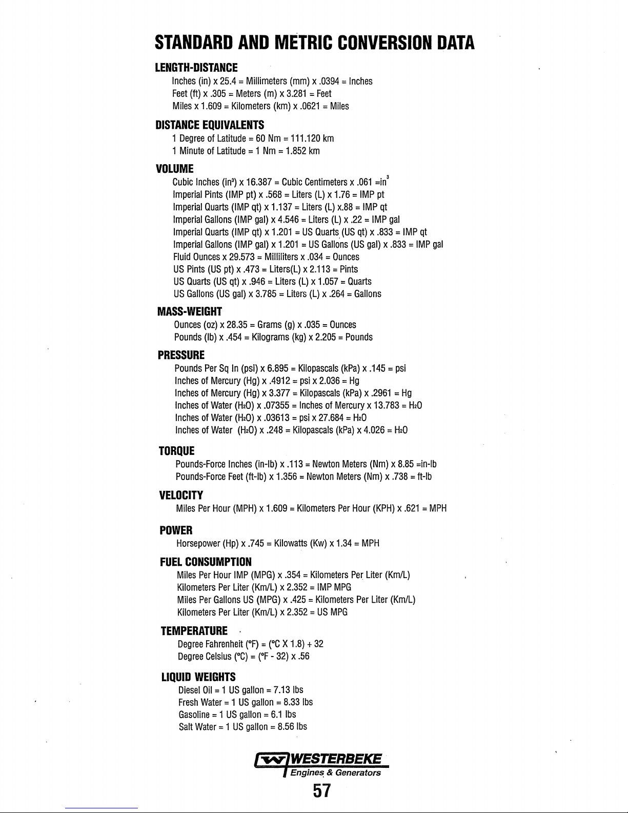
STANDARD
AND
LENGTH-DISTANCE
Inches
(in)
x
25.4
=
Millimeters
Feet
(ft)
x
.305
=Meters
Miles
x
1.609
=Kilometers
METRIC
(mm)
x
.0394
(m)
x
3.281
=Feet
(km)
x
.0621
CONVERSION
=
Inches
=Miles
DATA
DISTANCE
EQUIVALENTS
1
Degree
of
1
Minute
of
VOLUME
Cubic
Inches
Imperial
Imperial
Imperial
Imperial
MASS·
Imperial
Fluid
Ounces
US
Pints
US
Quarts
US
Gallons
WEIGHT
Ounces
Pounds
Pints
Quarts
Gallons
Quarts
Gallons
(US
(oz)
(lb)
PRESSURE
Pounds
Per
Inches
of
Inches
of
Inches
of
Inches
of
Inches
of
Latitude
Latitude
3
(in
) x
(IMP
(IMP
(IMP
(IMP
(IMP
x
29.573
pt)
x
(US
qt)
(US
gal)
x
28.35
x
.454
Sq
In
Mercury
Mercury
Water
(H20)
Water
(H20)
Water
(H20)
=
60
Nm
= 1
Nm
=
16.387
=Cubic
pt)
x
.568
qt)
x
1.137
gal)
x
4.546
qt)
x
1.201
gal)
x
1.201
=
Milliliters
.473
=
Liters(L)
x
.946
= liters
x
3.785
=Liters
=Grams
=Kilograms
(psi)
x
6.895
(Hg)
x
.4912
(Hg)
x
3.377
x
.07355
x
.03613
x
.248
=
111.120
1.852
km
Centimeters
=
Liters
=Liters
=
Liters
=
US
=
US
x
.034
x
2.113
(L)
x
(L)
(g)
x
.035
(kg)
x
=
Kilopascals
=psi
x
=
Kilopascals
=Inches
=psi
x
=
Kilopascals
km
(L)
x
1.76
(L)
x.88
(L)
Quarts
Gallons
=
Ounces
=Pints
1.057
=
x
.264
=Ounces
2.205
=Pounds
2.036
of
Mercury
27.684
(kPa)
x
.061
=
IMP
=IMP
x
.22
=
(US
qt)
(US
gal)
Quarts
=Gallons
(kPa)
x
=
Hg
(kPa)
x
x
=
H20
x
4.026
3
=in
pt
qt
IMP
x
.833
x
.145
.2961
13.783
gal
=
.833
=psi
=
=
H20
IMP
=
Hg
=
H20
qt
IMP
gal
TORQUE
Pounds-Force
Pounds-Force
Inches
Feet
VELOCITY
Miles
Per
Hour
(MPH)
POWER
Horsepower
FUEL
CONSUMPTION
Miles
Kilometers
Miles
Kilometers
Per
Per
(Hp)
Hour
IMP
Per
Liter
Gallons
Per
Liter
TEMPERATURE
Degree
Fahrenheit
Degree
Celsius
(°C) = (°F-
LIQUID
WEIGHTS
Diesel
Oil= 1 US
Fresh
Water
= 1
Gasoline= 1 US
Salt
Water= 1 US
(in-lb)
(ft-lb)
x
x
.745
(MPG)
(Km/L)
US
(MPG)
(Km/L)
·
(°F) = (°C
gallon=
US
gallon
gallon=
gallon
x
.113
x
1.356
=
1.609
=
Kilometers
=Kilowatts
x
.354
x
2.352
x
.425
x
2.352
X
1.8) + 32
32) x .56
7.13
lbs
=
8.33
6.1
lbs
=
8.56
lbs
=Newton
Newton
(Kw)
x
=
Kilometers
=
IMP
=
Kilometers
=
US
MPG
lbs
Meters
Meters
Per
Hour
1.34
=MPH
Per
MPG
(Nm)
Per
(Nm)
(KPH)
Liter
Liter
x
8.85
x
.738
x
.621
(Km/L)
(Km/L)
=in-lb
=
tt-lb
=MPH
57
Page 66

ENGLISH
TO
METRIC
CONVERSION
CHART
Multiolv Temoerature
Decree
Fahrenl'leit
Multiolv Acceleration
FooUSecond
lnch/secondl(lnJsec
Multiply Torque By
Pound-inch
Pound-foot llb·ftl
Multiolv Power
Horsepower
MultloiY Pressure
Inches
of water lin. H
Pounds/souare
Multiolv Enerav
British Thermal Unit
Foot-oound
kilowatt-hour
ll/lultiolv
Foot
candle lfc\
Multiolv Fuel Performance
Miles/oat
Gallons/mile
Multiolv Velocitv
Miles/hour lmile/hrl
("A
2
(ftlse~
2
)
llb·in.l
Cho)
or
Stress
0)
in.
(lb/in.
or
Work
(Btu)
(ft.Jb)
(kW·hr)
Uaht
CmDe/aall
Caat/milel
2
)
Bv
(°F·32) + 1.8
Bv
0.3048
0.0254
0.11298
1.3558
Bv
0.746
BY
02491
6.895
Bv
1055
1.3558
3,600,000.
3.6 X 10⁶
Bv
1.0764
By
0.4251
2.3527
Bv
1.6093
or
To
_gef
eguivalent number of:
Decree
Celsius
•c)
To
_g_et
eaulvalent number of:
Meter/secondl(m!s:zl_
Meter/secondl
To
get
equivalent number of:
Newton-meters
Newton-meters
To
_g_et
eauivalent number of:
Kilowatts
To
get equivalent number of:
Kdooascals
Kilopascals
To~
eauivalent number of:
Joules_{Jl
Joules
Joules
To aet eauivalent number of:
Lumens/meter'l(lmlm2)
To get
eg_uivalent
Kilometerslliter
Liter/kilometer
To aet eauivaleot number of:
Kilometers/hout
(~
= one
(mls:zl_
CN·ml
CN·ml
(kWl
(kPa)
(!<P§t.
(J)
W/s)
number of:
_{J<mfl)
1Llkn!l
(km/hr)
Multiolv Lenath
Inch
lin.)
Foot Itt\
Yard
lvdl
Mile lmile)
Multiolv Area
lnch2lin.2l
2
Cin.
2)
lnch
Foot2lft2l .
Vard2lvd2l
Multiolv Volume
lnch'lin. 3l
3
_,_-.
Ton
Ton
\
iaali
llbl
ltonl
(ton)
Force
Cozl
Quart latl
·Gallon
ll/lultiolv Mass
..
·-.
-
Pound
MuttiDtv
Kiloaram (kal
Ounce
Pound llbl
lnch!lin.
lnch3Cin. 3l
Vafd3Cvd3l
·-··
Bv
25.4
0.3048
0.9144
1.609
Bv To
6452
6.45
0.0929
0.8361
Bv
16387
16.367
0.0164
0.9464
··3.785
0.7646
Bv
0.4536
90"7.18
0.907
Bv
9.807
02780
4.448
To_g_et
E)guivalent
Miffimeters
Meters_(ml
Meters
Kilometers
_get
eauivalent number of:
Millimeters2lmm2l
Centimetersllcm2l
number of:
_(mml
(mJ
(km)
Mete~~:zt
Meters2(m2l
To_g_et
eauivalent number of:
Millimeters3(mm3l
Centimeters:!(_
Meters3Cm
To aet eauivalent number of:
KiiQgfams
Kifoarams
Tonne
To
aet eauivalent number of:
Newtons
Newtons
Newtons
Liters
Ut~
Liters
em~
CU
(L)
3
Cka)
(kg)
ft)
CNl
. (Nl.
CNl
)
58
Page 67

Page 68

1097WMDW-11/2005
 Loading...