

Page 1

OPERATOR'S MANUAL
&
INSTALLATION GUIDE
WESTERBEKE
KW
BTDA 15.0
BTDA 12.0
- 60 Hertz
KW
- 50 Hertz
,~
MARINE
GENERATOR SET
Publication #038663
August 1990
DIESEL
Edition One
WESJ'ERBEKE
WESTERBEKECORPQRATJON
AVON INDUSTRIAL PARK,
AVON,,vA
02322.
T£L.:(5"")588-77oo
Page 2

Page 3

SAFETY PRECAUTIONS
The following symbols appear
to
attention
dangerous to the operator.
and emphasize conditions potentially
in
this manual to call
nWARNINGjI
The above symbol
possible serious personal injury or loss of
The above symbol
personnel of possible damage to equipment.
Read
the manual carefully and thoroughly before attempting
dangerous conditions can exist and take necessary
precautions to protect personnel and equipment.
Fuels, exhaust gases, batteries, electrical equipment,
and moving and hot parts
could
recommended procedures carefully.
Always operate bilge blowers for at least five minutes
before starting a gasoline-fueled engine; ensure no
gasoline fumes are present before starting.
• prevent Electric Shock
to
resutt in serious personal injury or death. Follow
Shut off electric power before accessing electrical
equipment.
Use
insulated mats whenever working on electrical
equipment.
is
used in the manual to warn of
life.
ICAUTIONI
is
used in the manual to caution
operate the equipment. Know when
are
potential hazards that
•
Use
Extreme Care When Handling Engine
(A
constant danger
Do not fill fuel tank(s) while the engine
Do
not smoke or use
or the fuel tank.
•
Do
Not Atter or Modify the
Be
sure all fuel supplies have a positive shut-off
valve.
Be
certain fuel line fittings are adequately tightened
and free of leaks.
Make sure a fire extinguisher
is
properly maintained.
use. Extinguishers rated
propriate for
environment.
• Use Extreme Care When Servicing Batteries
Wear rubber gloves, a rubber apron, and eye
protection when servicing batteries.
Lead acid batteries emit hydrogen, a
plosive gas, which can be ignited by electrical
cing or by a lighted cigarette, cigar, or pipe.
smoke or allow
serviced.
vicinity to prevent electrical arcing during servicing.
Shut off all electrical equipment
of
explosion
an
open flame near the engine
Fuel
Be
ABC
all
applications encountered
an
open flame near the battery being
or
fire exists)
is
running.
System
is
installed nearby and
familiar with its proper
by the NFPA
highly-ex-
Fuel
are ap-
in
Do
in
this
ar-
not
the
is
Make sure your clothing
ly
shoes), and keep your skin surfaces dry when
handling electrical equipment.
Remove wristwatch and jewelry when working on
electrical equipment.
Do
not connect utility shore power to vessel's
Circuits, except through a ship-to-shore doublethrow transfer switch. Damage to vessel's
erator may resutt H this
Be
extremely careful when working on electrical
components. High voltage can cause injury or
death.
• Exhaust Gases
Ensure that the exhaust system is adequate to expel
gases discharged from the engine.
system regularly for leaks and make sure the
haust manifolds
ing exists.
Be
sure the unit and its surroundings
tilated.
Are
are
dry, not damp (particular-
AC
is
not done.
Toxic
Check exhaust
securely attached and no warp-
are
well-ven-
AC
gen-
ex-
• Ayoid
MOYing
Do
not service the unit while the unit is running;
situation arises
to make operating adjustments, use extreme care
to avoid moving parts and hot exhaust system
ponents.
Do
not wear loose clothing or jewelry when servicing
equipment; avoid wearing loose jackets, shirts or
sleeves, rings, necklaces, or bracelets that might
caught in moving parts.
Make sure
tightened. Keep protective shields and guards in
their respective place
Do
not check fluid levels or the drive-belt's tension
while the unit
Do
not work on the equipment when mentally or
physically incapacitated by fatigue.
parts
in
which it is absolutely necessary
all attaching hardware is properly
at
all
times.
is
operating.
if
com-
be
a
15.0KWBTDA
1
Westerbeke Generators
Page 4

FOREWORD
Thank you for selecting a Westerbeke marine product for your use.
We
at Westerbeke
are
pleased to have you as a customer.
Read this manual carefully and observe all of the safety precautions indicated. Operating
procedures, periodic preventive maintenance procedures, installation checks, system descriptions
and minor adjustment procedures are included so you can operate your equipment safely and
properly, maintain the equipment at a high level of efficiency, and expect dependable performance
and long service life in return.
Product Software Disclaimer
all
Product software of
kind; such as brochures, drawings, technical data, operator's and
workshop manuals, parts lists and parts price lists, and other information, instructions and
specifications provided from
and; accordingly,
is
Sources
provided
Westerbeke cannot be responsible
or
representations with respect thereto, Including the accuracy, timeliness
In
thereof, and will
connection with,
no event be liable for any type of damages
or
arising out of, the furnishing or use
other than Westerbeke,
to
Westerbeke customers only as a courtesy and service.
for
the
content
of
is
not wtthin Westerbeke's control
such software, makes no warranties
or
completeness
or
Injury Incurred
of
such software.
For example, components and subassemblies incorporated in Westerbeke's products and supplied
as
by others (such
engine blocks, fuel systems and components, transmissions, electrical
components, pumps and other products) are generally supported by their manufacturers with
their own software, and Westerbeke must depend on such software for the design of Westerbeke's
own product software.
by
changes made
Westerbeke's suppliers, of which Westerbeke rarely has notice in advance,
Such software may
be
outdated and no longer accurate. Routine
are frequently not reflected in the supplier's software until after such changes take place.
In
Westerbeke customers should also keep in mind the time span between printings of Westerbeke
product software and the unavoidable existence of earlier, non-current, Westerbeke software
editions in the field. Additionally, most Westerbeke products include customer-requested special
features that frequently do not include complete documentation.
In
summation, product software provided with Westerbeke products, whether from Westerbeke
or other suppliers, must not and cannot be relied upon exclusively as the definitive authority
on the respective product.
It not only makes good sense but
representatives of Westerbeke or the supplier
and currency of the product software being
Westerbeke Generators 2
is
imperative that appropriate
in
question be consulted to determine the accuracy
consulted by the customer.
15.0KWBTDA
Page 5

Warranty Procedures
Should your unit require special attention, contact your Westerbeke dealer for assistance. The
Westerbeke Service Organization
is
trained to provide the support necessary to ensure long-term
dependable performance.
If,
within
received a Customer Identification Card (figure
60
days of submitting the Warranty Registration Form for your unit, you have not
1.2)
registering your warranty, please contact
the factory in writing with model information, including the unit's serial number and commission
date.
tno:
IEST£RBEKE
AVOM
nON,
Mall
CORPORHIOII
INDU$TlUAL
IIA
02122
To:
PARk
CUSTOMER IDENTIFICATION
.~
loIaph
Str
..
U 12234
III
'lbA
1nll9
t
Alolu.
140
.... 1 IS
hpi
....
Unit
1.0.
Plate
For
future
repair or warranty
erence,
service,
ref-
Westerbeke
suggests that you fill
the blank spaces in figure
1.3
with the infor-
mation
from
your
machine.
figure 1.2: Customer Indentification
in
•
figure 1.3: Unit I.D. Plate
Card
15.0KW BTDA
3
Westerbeke Generators
Page 6

Table
Of
Contents
Section
SAFTEY PRECAUTIONS
FOREWORD
PRODUCT SOFlWARE DISCLAIMER
WARRANTY PROCEDURES
GENERAL INFORMATION
PROTECTING YOUR INVESTMENT
15.0
BTDA GENERAL SPECIFICATIONS
15.0
BTDA SYSTEM SPECIFICATIONS
INSTALLATION CHECKS
EXHAUST SYSTEM
RAW WATER INTAKE SYSTEM
COOLING SYSTEM
-
14
Page
1
2
2
3
11
12
13
• 16
18
23
27
28
ENGINE CONTROL
REMOTE
REMOTE PANEL
WIRING DIAGRAM # 36474
PREPARATIONS FOR STARTING
STARTING
STOPPING PROCEDURE
FUEL
LUBRICATION SYSTEM
DC CONTROL CIRCUIT
WIRING DIAGRAM #36411
COOLING SYSTEM (FRESH WATER/RAW WATER)
BT
OPTIONAL VOLTAGE REGULATOR
OPERATION
PROCEDURE
SYSTEM
GENERATOR
PANEL
29
30
31
34
35
38
40
45
47
51
56
62
Weslerbeke Generators
4
15.0KW BTDA
Page 7

Table
Of
Contents
(continued)
Section
SHORE POWER CONNECTIONS
3 PHASE BT GENERATOR
3
PHASE VOLTAGE REGULATOR
ENGINE TROUBLESHOOTING
GENERATOR TROUBLESHOOTING
PERIODIC MAINTENANCE
TABLE
TIGHTENING TORQUES
LAY-UP
SPARE PARTS
OF
STANDARD HARDWARE
AND RECOMMISSIONING/WINTERIZING
-
AND ADJUSTMENTS
Page
64
68
69
74
77
78
64
86
90
1S.0KW BTDA
S
Westerbeke Generators
Page 8

RIGHT SIDE OF GENERATOR
AC
Water
Exhaust
Injected
Elbow
Exhaust
Manifold
Fresh
Water
Fill
Cap
Lube
Oil
Fill
Cap
Water
\
Temperature
Sender
DC
Charging
Alternator
Belt
Guard
Westerbeke Generators
6
15.0KW
BTDA
Page 9

LEFT SIDE
OF
GENERATOR
Water
Fuel
Fuel
Raw
Fuel Pressure Gauge
Temperature
Switch
Filter
Water
Pu
Oil
Pressure
___
~.
Sender
Lube
Oil
.------~
Oil Pressure Switch
Dipstick
..
---
Lube
Preheat
Oil
Solenoid
Filter
Starter
Control Panel
Generator
C
Battery
Ground
with
Solenoid
Switch
Data
Plate
Connection
15.0KW BTDA
7
Westerbeke Generators
Page 10

(This
page intentionally left blank)
15.1
Westerbeke Generators
8
15.0KW
BTDA
Page 11

(This page intentionally left blank)
15.0KW
BTDA
9
Westerbeke Generators
Page 12

(This page intentionally left blank)
Westerbeke Generators
10
15.0KW
BTDA
Page 13

15.0KW BTDA MARINE DIESEL GENERATOR SET GENERAL INFORMATION
Introduction
This manual contains equipment operating procedures and information to help the operator
maintain the marine equipment
carefully. A planned maintenance program
will
resuH
in
better equipment performance and longer equipment
problem
is
the most important step to satisfactory repair; therefore, a troubleshooting table
in
proper working order. Study and follow the instructions
is
included in this manual. Adhering to the program
me.
Proper diagnosis of a
is
included.
Service And Parts Manuals
For in-depth maintenance and repair, the service manual for the
15.0KW
BTDA
can be purchased
from your local dealer.
Product Description
The diesel engine closely resembles the gasoline engine since the mechanism is essentially
the same. The cylinders
are
arranged above a closed crankcase; the crankshaft
is
of the same
general type as that of a gasoline engine; and the diesel engine has the same type of valves,
camshaft, pistons, connecting rods, and lubricating system.
Therefore, to a great extent, a diesel engine requires the same preventive maintenance
gasoline engine. The most important factors
are
proper ventilation and proper maintenance of
as
the fuel, lubricating and cooling systems. Replacement of fuel and lubricating filter elements at
is
the time periods specified
manatory, and frequent checking for contamination (that
sediment, or algae) in the fuel system
is
also essential. Another important factor
is,
is
the use
water,
of the same brand of high detergent diesel lubricating oil designed specifically for diesel engines.
Be
careful not to put gasoline in the diesel fuel tank(s). Gasoline does not have the same
lubricating qualities
as
diesel fuel; consequently, gasoline in the fuel lines will damage components
in the fuel injection pump and fuel injectors.
The diesel engine differs from the gasoline engine; however, in that the functions of the
carburetor and ignition system
are
performed by the fuel injection pump and the fuel injectors.
Ignition results from a higher compression ratio which eliminates the need for spark plugs, but
neccitates the use of a heavier block.
a
15.0KW BTDA
11
Westerbeke Generators
Page 14

Protecting Your Investment
The five most important steps to insure
1.
Proper Installation.
In
particular, the use of
intrusion into the engine via the exhaust
2.
Avoid overcranking. This
3.
Change the lubricating
4.
Maintain the cooling system.
5.
Winterizing your Westerbeke product.
can
fill the engine with
oil.
long engine
elbow
Ine
are:
an
anti siphon break to preclude
is
essential.
raw
water.
raw
water
Ordering Parts
Whenever you require
(I.e.
15.0
~
BTDA)
the data
plates located on the exhaust manifold and on the generator end.
us with this information so
replacement parts, always provide the generator model number designation
, engine serial number, and generator serial number as they appear on
You
~
provide
we
may
properly identify your generator set.
In
addition, include a
complete part description and part number for each part needed (see the separately furnished
Parts List).
or generic parts
Also,
be
sure to insist upon Westerbeke factory packaged parts because "will fit"
are
frequently not made to the same specifications as original equipment.
Note that component
is
the pulley/drive
are determined by the engine; imagine
as the front of the engine: the
Westerbeke generator sets
locations in the manual are referenced from the front of the engine which
bett
end.
(The
flywheel/generator end
is
the rear end.) Left and right sides
straddling the engine and facing in the same direction
left side
are
thoroughly checked and given a final run under various load
is
at your
left,
the right side at your right.
conditions before leaving the factory. Test running the generator ensures dependable operation,
long service
Care at the factory during
life,
and a satisfied owner.
assembly and thorough testing has resulted in a Westerbeke diesel
engine-driven generator capable of many thousands of hours of dependable service. However,
the manufacturer cannot
in
which the unit
is
operated and serviced
control the installation of the generator in the vessel or the manner
in
the field. That part
is
up to the buyer/owner-operator.
Westerbeke Generators
12
15.0KW BTDA
Page 15

15.0 KW BTDA General Specifications
Engine Type
Governor
Combustion Chamber
Bore
& Stroke
Piston Displacement
Firing
Order
Direction of Rotation
Maximum Torque
(at
Compression Ratio
Compression Pressure
lim~
Valve
Timing
1800
rpm)
Diesel,
four·cycle, four-cylinder, fresh water-cooled,
vertical in-line overhead valve mechanism
(30
hp
at
1800 rpm maximum).
Mechanical type (integral of the injection pump)
Swirl type
3.50 x 3.50 inches (88.9 x
134.8 cubic inches (2.209
89
mm)
I~ers)
1-3-4-2
Clockwise, when viewed from the front
148
Ib-It
(20.46 kg-m)
21:1
2
47'
)
at 200 rpm
2
)
BTDC
ABDC
427 psi
384
(30
kg/cm
psi (27.0 kg/cm
Intake Opens 17"
Intake Closes
Valve
Seat Angle
Valve
Clearance
(engine cold)
Engine
Speed
Dimensions
Weight
Fuel
Consumption
Inclination
Exhaust
Exhaust Closes
Intake
Exhaust
Intake 0.012 inches
Exhaust 0.012 inches (0.3
1800 rpm
1500 rpm
Opens 51'
45'
30'
60
Hertz
50
Hertz
13'
BBDC
ATDC
(0.3
mm)
mm)
Height: 25.74 inches (653.8
Width: 21.19 inches (538.2
mm)
Length: 39.63 inches (1006.6
765
Ibs
(347
kgs)
1.8
gph (6.81Iph) at full rated output
(approximate)
15'
Continuous
Temporary 20'
(not to exceed 20 min.)
mm)
mm)
15.0KW
BTDA
13 Westerbeke Generators
Page 16

15.0 KW
BTDA
Fuel System
General
Fuel
Fuel
Injection Pump
Fuel Injection Timing
System Specifications
Open flow,
No.
2 diesel oil (cetane rating of 45 or higher)
Distributor Type
0"
TDC
sen
priming·
(VE)
Diesel
(Top Dead Center)
one bleed point
KiKi
Nozzle
Fuel
Filter PN#024363
cleaner
Air
Air Flow (engine combustion)
Cooling System
General
Operating Temperature
Fresh Water Pump
Raw
Water Pump
Raw
Water
Flow,
at
1800 rpm
(measured before discharging
into exhaust
System Capacity
elbow)
(fresh water)
Throttle
type
Spin-on (Replaceable)
screen type - cleanable
Metal
cfm
(1.9
70.0
cmm)
Fresh water-cooled block, thermostatically-controlled
wtth heat exchanger.
170 - 190" F (77 - 88'
C)
Centrifugal type, metal impeller, bett-driven
Positive displacement, rubber impeller, gear-driven.
6.0 gpm (22.7
10.0 qts
Ipm)
(Itters)
Lubrication
General
Oil
Filter PN# 035828
Sump Capacity (not including filter)
Operating
Oil
Grade
Westerbeke Generators
System
Oil
Pressure (engine hot)
Pressure fed system
Full
flow,
paper element, spin-on type
5.3
U.S.
qts
(5.0
50 -65
API
psi
service
(3.5
CC -CD
14
Itters)
plus filter/cooler assembly
- 4.57 kg/cm
2
)
15.0KWBTDA
Page 17

15.0
KW
BTDA System Specifications (continued)
Electrical System
Starting Battery
Battery Capacity
DC
Charging Alternator
12·Vott,
125
51
(-)
negative ground
ampere·Hours
Amp rated, belt·driven
Starter
Starting Aid
DC
No·Load Current
DC
Cranking Current
AC
Generator
General
12·Volt,
reduction
Glow plugs, sheathed type
± 2 % of rated Amps
280
Amps (engine cold)
Brushless, four·pole, revolving field.
Pre·lubricated, single·bearing
design.
Reconnectable, single·phase transformer
regulation (optional solid·state voltage regulation).
Voltage120
220 Votts •
or 120/240 Volts •
50
Hertz.
60
Hertz
Voltage regulation: ±5% no load to full load.
Frequency regulation:
±3
Hertz
(5%)
no load
to full load.
Rating (Volts
AC)
15.0KW BTDA
60
Hertz (1800
50
Hertz
Generator Cooling
(60
Hertz) at 1800 rpm
(1500
rpm)
rpm)
Air
Requirements
NOTE: Increase air supply
Engine Combustion Air Requirements
(60
Hertz),
at
1800
rpm
120 Volts125 Amps
120/240 Volts125/62.5 Amps
220 Volts60 Amps
225
• 250 cfm (6.37 • 7.08
15%
for
50
Hertz operation (1500 rpm).
70
cfm
(1.89
cmm)
15
cmm)
Westerbeke Generators
Page 18

15.0
KW
BTDA System Specifications (continued)
Tune-up Specifications
Injector Pressure
Engine Timing
Governor
Generator Compartment
Ambient Temperature
NOTE:
generator compartment ambient temperature below 104°
Forced ventilation should be provided
1920 +
Static timed - drop valve method
0.180 ± .005 inches
0°
1 mm of cam lift using measuring device for
injection pump.
Hydraulic mechanical type in the injection pump
104° F (40"
T.O.C.
71
- 0 psi
or
#1 cylinder.
C)
Maximum
as
(135
+ 5 - 0 kg/cm2)
BTDC
needed to maintain
F.
Westerbeke Generators
16
15.0KW BTDA
Page 19

General
the boats on which Westerbeke generators are installed vary in design, installation
Since
procedures will vary according to your boat's specific design. The intent of this section
not to advise boatyards or installers
However, the owner/operator must
on
procedures already well-developed and well-understood.
realize there are details of the installation which require
is
periodic checks to ensure the best operating conditions for the equipment and safe operating
conditions for the
in
the vessel
personnel
are
of prime importance.
Factors in the installation that must
on
board. Proper location and installation of the diesel generator
be
considered
are:
(1)
ventilation; to aid in cooling the
generator end, to provide air for engine combustion and to remove heat produced by the
(2)
the
AC
e)(haust
expel exhausl
and
engine while operating,
and to quiet the exhaust and to
electrical connections; both
supply of properly filtered fuel to the fuel pump
system; to properly discharge
gas,
(3)
the cooling water supply,
DC,
and
(5)
a fuel system that will provide
on
the engine.
~AOTIONI
raw
cooling water
an
unrestricted
(4)
the
Fill The Engine With
For safety reasons, the generator's engine
oil
for shipment. Before leaving the factory, however, each generator
is
thoroughly tested
set
things, provides
all
WITh
oil in
internal parts with a coating of
011
Before Starting
is
not filled with lubricating
ITS
engine. This testing, among other
oil.
This oil acts
as
a preservative, providing reliable protection against corrosion for at least
one year ~ the generator
is
properly stored.
Do
not overfill.
Inspection of Equipment
is
The generator
equipment
shipped from the factory securely mounted and properly crated. Accessory
is
shipped
in
a separate small
box,
usually packed wtthin the generator's crate.
Before accepting shipment of the generator set from the transportation company, the crate
should
you
delivery receipt.
sure that the proper notation
are your protection against
be
opened and the contents inspected for concealed damage.
If
damage
is
noted,
should require the delivery agent sign "Received in damaged condition" on the proper
Also,
check the contents of the shipment against the packing list and make
is
made ~ any discrepancies exist. These noted discrepancies
loss
or
damage. Claims concerning loss or damage must
be
made to the carrier, not to Westerbeke Corporation.
15.0KW BTDA
17
Westerbeke Generators
Page 20

Generator Mounting - Location
complete generator
The
un~
is
mounted on lightweight rails by means of four flexible isolatro
mouints that help prevent the transfer of vibration from the generator to the
generator mounting
several 1/2 inch boh holes so bohs can
be
employed to properly
rail
ahs
secure the generator to its mounting platform.
rails.
Eachj
figure 3.3:
The mounting location
water and water from above cannot splash or drip
engine and generator
repairs
to provide fresh
~nerator
Mounting
/llJ.lS1
be
/llJ.lS1
be
dry, above low-lying vapor
accessible for minor servicing and repairs. Access for major
should be given consideration
cooling air for the generator end, for engine combustion needs, and to remove
as
on
the generator or drive engine.
well.
The generator set
areas,
and
/llJ.lS1
in
heat produced by the engine while operating. The generator set needs fresh
location
generator
be strong enough to support the generator during
in
the vessel ~ is
area.
The platform on which the generator and its mounting rails are located
installed. Hot generator discharge air
all
angles of vessel operation.
/llJ.lS1
1/2-
MOUNTING
HOLES
an
area where bilge
The
drive
be properly ventilated
cool air
be removed from the
in
whatever
/llJ.lS1
15.0KW BTDA
18
Westerbeke Generators
Page 21

Generator Mounting - Rigging and Lifting
The generator
is
fitted with lifting eyes. Rope or chain slings capable of supporting the generator's
weight should be attached to the eyes and the generator lifted by means of tackle attached
to these slings. The lifting eyes have been designed to carry the full weight of the generator;
therefore, auxiliary slings are not required or desired.
ICAUTION!
Sling Lifting Angle Must Not Exceed 10 Degrees
Slings must not be so short as to place signfficant stress
eyes.
Strain placed on the generator's lifting eyes by the lifting sling must not be in
excess
of
10
degrees from !he vertical plain.
10'
SLING LIFTING
ANGlE
EXCEED
MUST
10'
LIFTING
NOT
on
the generator's lifting
EYE
ENGIME
figure 3.4: Lifting Angle
The general rule in moving generators
and firmly fixed in place. Move the engine a little at a time and see that
ported. Eliminate the possibility of accidents by avoiding haste.
tts
by
crankshaft pulley.
In
certain sttuations
tions other than the horizontal posttion. Certain sttuations exist
is
to see that all equipment used
Do
tt
may
be necessary to lift the engine in posi-
by
is
amply strong
tt
is
firmly sup-
not lift the generator
which the engine must
be lowered endwise through a small hatchway which cannot be made larger. Under these
conditions,
ff
the opening of the hatchway
is
extremely small,
tt
is
possible to reduce, to
some extent, the outside dimensions of the generator by removing external components
such
as
the cooling system's piping, the heat exchanger, certain filters, the mounting rails
and other obstructive equipment. This accessory equipment should be removed by a
competent mechanic and special care should be taken to avoid damage to any exposed parts.
In
addition, be careful to prevent dirt from entering any opening created by the removal of
equipment. Removed parts should be returned to their respective position once the
ator
is
in
tts
In
case
installation
tt
becomes necessary to hoist the generator front -end upwards or generator-end upwards,
area.
Replace gaskets
as
needed for the parts that were removed.
gener-
the attachment of lifting slings must be done carefully to avoid the possibility of damaging the
parts
on
which the weight of the slings may bear. Special rigging work
is
best done by someone
experienced and competent in handling heavy machinery.
Westerbeke Generators
19
15.0KWBTDA
Page 22

Ventilation
is
The ventilation requirements of the generator sets include the following: combustion air
quired for the engine cylinder; cooling air
is
required for the generator end and also for
re-
removing the head produced by the generator's engine during operation; and ventilating air
is
required
the generator
Keep
to
clear the bilges below the generator, as well
is
located, of potentially toxic and flammable diesel vapors.
in
mind that hot air rises, so heated air should be removed from the upper area of the
as
the compartment in which
generator compartment and cool fresh air should be directed to the lower areas of the
compartment. Ventilation should be accomplished with the aid of blowers especially when the
is
vessel
not underway. Refer to the
the airflow requirements of the
System
Fuel
ge,!1erator
"SYSTEM
set.
SPECIFICATIONS" section of this manual for
The generator
aJ.lW.
have
~s
own fuel supply line; in other words,
~
aJ.lW.
have
~s
own fuel
tank pickup tube and primary filter/water separator. Do not tee off another engine's fuel
supply. The fuel system should
installed
in
such a manner
as
to
allow the engine-
be
mounted fuel pump to pump and maintain a positive inlet pressure to the injection pump
all
under
operating conditions,1 1/2 - 2 p.s.i.. The minimum size of the fuel supply line
and fuel return line is 1/4 inch, inside diameter, and there should be a primary fuel filter/
water separator installed between the fuel tank and the fuel pump.
on
stalled
the engine, between the fuel pump and the injection pump; this filter has a
Only one fuel filter
is
replaceable filter element.
The fuel tank's fuel pickup tube should
be
strainers should
incorporated in the fuel pickup tube.
clear and unobstructed.
No
screens or gauze
be
Make sure that the fuel supply and return lines are secruely anchored to prevent chafing
all
and that
system has a positive shut-off valve; know
fittings are sufficiently tightened to prevent leaking. Also, make sure your fuel
ns
locaton and how ~ operates.
NOTE:
in
Do
not use spring-loaded check valves
lieu
of mechanical shut-off valves. This type valve can create fuel
in
the fuel supply line
starvation problems for the engine's fuel system.
Fuel
tanks that
connection at the tank extending down into the tank
are
located below the engine's fuel system level must have their fuel return
in
the same manner as the pickup tube;
otherwise, air will replace fuel Siphoning out of the engine's fuel system through the return.
in-
Make sure the fuel tank filler
awash. The fuel tank's vent should be routed so
Be
sure there
Be
familiar with its use.
applications
Westerbeke Generators
is
properly sealed to prevent water entry should it become
as
to prevent water enter
is
a fire extinguisher installed near the unit and that it
An
in
this environment.
extinguisher
w~h
the
NFPA
rating of
20
ABC
as
well.
is
properly maintained.
is
appropriate for
15.0KW BTDA
all
Page 23

011
Drain Hose
An
oil sump drain hose is installed on the engine wtth the discharge end secured by a
bracket at the front of the engine.
cap and the discharge end of the hose from the support bracket and lowering the hose
into a container. The hose cap
tended. or have a pup added, for easier removal of the old
Oil
fttting
may
is
1/4 inch
be
drained from this hose by removing the
NPT
(National Pipe Tap) and can
oil,
if desired.
be
ex-
Connecting Pressure Sensing Devices
Oil
pressure sensing devices, such
engine's oil gallery wtth the use of extended nipples or tees. The reason
continued engine vibration
If
these fittings fail during engine operation, lubricating oil will be lost and internal engine
damage will
When additional sensing devices such
function on engine
the oil gallery using an appropriated grade of lubricating oil hose. Any fittings used to con-
nect the hose to the gallery
be
not
Electrical System
The electrical system should
down with clamps or plastic ties and that
enough to prevent chafing from vibration.
are tight and that they are made to the appropriate terminals.
DC
Electrical Connections
resutt.
oil pressure, these devices
used for this application.
causes fatigue of the ftttings used to
mug
be
checked to make sure all wiring harnesses are properly tied
to
011
Gallerlos
as
senders and swttches, must not be connected to
is
simply that
make
such a connection.
as
swttched or sensors need to
mug
be bulkhead-mounted and connected to
be of steel or malleable iron composttion. Brass must
all
wiring harnesses
Check to make sure
are
all
be
installed that
spaced at intervals close
engine harness connections
an
A common ground for the negative
of the generator, next to the starter,
tery ground should be connected
Connect the battery's positive
tion.
15.0KWBTDA
(+) connection to the starter solenoid tagged for this connec·
To
avoid
an
overcharging condition, and a possible equipment failure
do not disconnect the
(-)
DC
terminal connection
in
the form of a threaded grounding stud.
at
this stud.
is
found at the bellhousing
fAOTIONI
DC
battery source while the engine
21
The
bat-
is
running.
Westerbeke Generators
Page 24

Generator
Make sure that the
correct and in acordance with the specific
this
leads
(AC
Output)
AC
output connections within the generator's
AC
Load Connections diagram found later in
manual.
are
(See
the "BT
protected against chafing as they exit the generator housing
GENERATOR"
section of this manual.) Make sure the
AC
terminal block
IWARNiNGI
Do not smoke or allow an open flame near batteries. Lead acid batteries emit
hydrogen, a
Batteries
highly-explosive
gas.
are
AC
Make sure the positive
the starting solenoid. The negative
ground stud tagged at the rear of the engine
(+) battery connection
(-)
is
connected to the battery connection of
battery connection should be connected to the
block.
!WARNiNGJ
Protect Yourself When Servicing The Battery
When servicing the battery of checking the
rubber apron, and eye protection. Battery acid may
eyes inadvertently when removing the
Check the battery's electrolyte level and specific gravity to ensure maximum engine
starting efficiency. Make sure the battery's terminals
electorlyte
electrolyte caps.
level,
wear rubber gloves, a
splash on the skin or into the
are
clean and tight.
Westerbeke Generators
22
15.0KW BTDA
Page 25

Exhaust System
Carbon monoxide is a dangerous
and
monoxide inhalation or poisoning
• Dizziness • Vomiting
• Intense Headache • Muscular Twitching
• Weakness and Sleepiness • Throbbing
Carbon monoxide gas Is deadlyl
is
potentially lethal. Some
tNAANiNGI
gas
that can cause unconsciousness
of
the symptoms or signs of carbon
are
listed below.
in
Temples
The generator should have its own separate exhaust installed so that the entry of
into the engine's exhaust
or while the vessel is under sail or power
rolling or pitching. Special atlention
secure, tight and free
The
raw
water supply through-hull sea cock fittings
scoop types or weed less scoop types must not
of
raw
water through the cooling system filling
When a water lift type exhaust system is used (figure
mounted
downward into the exhaust muffler. Loops
exhaust elbow and the water lift muffler should
as close to the engine as practical.
manHold
of
leaks.
and cylinders is prevented while the engine is
in
~
which case the vessel
be
taken to
be
the
make
~
be
of
used,
as they tend to encourage siphoning
exhaust.
may
experience heeling,
certain the exhaust system is
the flush-hull type. High-speed
3.13.4), the exhaust muffler should be
The
exhaust discharge should always drop
in
the exhaust hose between the water-injected
be
avoided,
as
these
will
trap and hold water.
raw
nOl
water
running,
figure 3.13.4: Water Lift Exhaust System
Westerbeke Generators
23
15.0KWBTDA
Page 26

u.n.",
II"
...
UUI_
IU'"
"I('
UI(
figure 3.13.5: Siphon Break
For installations where the exhaust manHold/water-injected exhaust elbow
below the vessel's water line, provisions
ID~tallatioD
~
be
is
close
to
or
made to install a siphon-break or a vent
in the raw water supply hose to the water-injected exhaust elbow. (figure 3.13.5) This
stops the
flow of
exhaust and
~
be looped above the water line. This siphon-break or vent
the water line during
used,
~
empty of water when the engine
to
prevent siphoning.
Dry
stack-type exhaust systems (figure 3.13.6)
exhaust
manHold
supported and
must be made for discharging the engine's
raw
water that runs through the
engine cylinders when the engine
raw
water cooling system from filling the
is
shut down. This
raw
water supply hose
~
always be above
all angles of vessel operation to prevent siphoning. The vent, when
have its vent hose or tube routed so it can remain above the water line and
is
shut down. This allows air to enter through this vent
must
be attached to the generator engine's
by means of a flexible connector pipe. This system
~
be properly
insulated to prevent water from entering into the engine's cylinders. Provisions
raw
cooling water .
..........
c.
c
....
c.
~
i I
15.0KWBTDA
"Z.C.
....
~~3
-
figure 3.13.6: Dry Stack Exhaust
c_
••••
,
pc.
LJ.C
•••
~E
..
•••
•
c.
_ ..
e.
J
.....
c ,.
....
ue
..
........
"Jrra
.. e
_
f'
.........
•• • S.C
a.c.
""""=="===~~~~~~~!:.=c.
24
~oc..7;;J--
........
_
)
..
e •
•••
Westerbeke Generators
Page 27

Exhaust Elbow Installation
The Westerbeke Corporation offers a 7Z' exhaust elbow
can install on your engine's exhaust
the exhaust
elbow purchased for your generator.
manHold.
Refer to the instruction below when installing
NOTE: Fabricated exhaust elbows or risers attached to the exhaust
manHold
1.
Coat only one side
shall not exceed 8 Ibs when unsupported.
of
the exhaust
gasket with "High Tack" (Manufactured
by Permatex Company, Brooklyn,
N.Y.)
adhesive sealant. Place this coated surface against the exhaust manHold's
ex-
haust port flange (the gasket should
stick to the flange without falling off).
2. Place the clamp over the elbow's
flange.
against the exhaust manHold's flange
Place your exhaust elbow
so
the exhaust manHold's flange rests
snug against the exhaust elbow's flange
with the gasket centered between the
two. Now
slip the exhaust clamp over
both flanges.
as
well
as
an
exhaust riser you
#38374
Elbow
3.14:
3.
A Tighten the clamp just enough
figure
so the exhaust elbow can remain attached to the
B.
The exhaust elbow discharge
~
be
directed downward
Exhaust Elbow Installation
manHold
and still be rotated.
so
the mixture of
water and exhaust gases will flow/fall downward into the exhaust muffler which must be
positioned
hose connected between the exhaust
and possibly allow water to flow back into the engine during starting or
4. Adjust the
is
acquired.
5. Carefully tighten the clamp between 2 to 3
below the exhaust elbow. There should be no loops or rises in the exhaust
elbow by rotating
elbow and the muffler,
it
until the desired alignment with the exhaust piping
Ib-It,
or 24 to 35 Ib-in, or 0.27 to
as
these would trap water
at
shut down.
0.41 kg-m.
r.:;AOTIONj
3 Lb·Ft Torque Umlt
Approach the 3 Ib-It torque limit with caution. The clamp's threads will
H more than 3 Ib-It
break
If
a leak exists, correct it immediately .
is
applied to the clamp.
raw
. Westerbeke Generators
25
15.0KW BTDA
Page 28

Exhaust Back-Pressure
The exhaust discharge hose
and minimal run to prevent excessive exhaust
pressure. Exhaust back-pressure should
before a generator
Excessive back-pressure will affect the engine's
formance which affects generator
To measure
manometer, a pressure gauge, or a water column.
boatyard or marine mechanic should have a manometer
or a pressure gauge.
have a tapped hole in
be
drilled and tapped for a 1/8 inch
dry area of the elbow.
Measure the engine's back-pressure at the exhaust
elbow while the generator
Refer
to the pressure specifications listed below. \
A water column can be made
tube and taping one end of the tube along a
yardstick and fitting the other end of the tube
a 1/8 inch
NPT
is
for
back-pressure, use a mercury
(National
must be of adequate size
back-
be
checked
put into service (figure 3.15.1)
per-
AC
power output.
A
If the generator set does not
~s
exhaust elbow, one
NPT
f~ing
is
under a full-load.
by
taking a clear plastic figure 3.15.1: Exhaust Elbow Connections
Pipe
Tap) pipe fitting.
II!!.&:
in
the
w~h
..
..
"
"
H Exhaust
,n
..
~
~I
-Insulation
Exhaust
Elbow
Mercury
Manometer
Measure the engine's back-pressure in the dry
area of the exhaust elbow while the generator
under a full-load.
NOTE: Dimension A (figure 3.15.5)
cannot exceed 27 inches of water.
Back
pressure,
ment, should not exceed the following specifica-
tions:
2 inches of mercury
27 inches of water in a water column
15.6 ounces psi
1.0
1.11
psi
kg/cm
as
measured by a gauge instru-
2
"--.
is
1/8
NPT Plug
\
15.0KW BTDA
26
Westerbeke Generators
Page 29

Exhaust System Failures
an
When the engine's raw water is fed into
exhaust system so that the full stream of this water
strikes a surface, errosion takes place. This errosion may cause premature failures. The proper
design of either a water jacketed or water injected
raw
requires that the
not directly strike a surface.
be
as
low
as
possible, which can be achieved
water inlet be posttioned so that the entering stream of
In
addition, the veloctty of the entering
"wet" exhaust system to prevent this problem
raw
water does
raw
water stream should
by
having inlet fittings as big in diameter
as
possible.
is
The best protection against carbon monoxide poisoning
a daily inspection of the complete
exhaust system. Check for leaks -around manifolds, gaskets, and welds. Make sure exhaust
lines are not heating surrounding areas excessively.
If
situation immediately.
you notice a change
shut down the unit immediately and
in
the sound or appearance of the exhaust system,
have
the system inspected and repaired at once
excessive heat
is
present, correct the
by
If
qualified mechanic.
Make sure there are no unnecessary objects suspended from any portion of the exhaust lines.
Exhaust risers installed off the exhaust manifold should not exceed 8
Ibs in total weight when
rigidly constructed. Excessive weight could cause deflection or distortion of the manifold resulting
in
damage and/or internal leaks. Inspect insulated portions of the exhaust system to ensure
there
is
no deterioration of the insulation.
a
ICAUtloN)
Do Not Overcrankl
resu~
Prolonged cranking intervals without the engine starting can
raw
filling the exhaust system with
raw
because the
water pump
water cooling system during cranking. This
engine's cylinders by
way
of the exhaust
system fills. Prevent this from happening by closing the
water coolant. This may happen
is
pumping
raw
water through the
raw
water can enter the
manHold
once the exhaust
raw
water supply
through-hull shut-off, drain the exhaust muffler, and correct the cause
for the excessive engine cranking needed to obtain a start. Engine
raw
water entry
this in mind.
Raw Water
damage resulting from this type of
The owner/operator should
keep
Intake System
Make sure the intake system (raw water cooling system)
are
the hull inlet, sea cock and strainer
at
least one size greater than the inlet thread of the sea water pump. The strainer should
be
of the type that may be withdrawn for cleaning while the vessel
be mounted below the water line to ensure
unobstructed. Sea cocks and strainers should be
self-priming. Inspect the
is
IlQ1
a warranted.
is
in
proper order. Check that
is
at
raw
make sure there are no collapsed sections, which would restrict water flow. Make sure
The
there are no air leaks at any of the connections.
as
tioned at the vessel water line or below so
to
sea water strainer should
be
self primed.
in
raw
sea and should
water lines to
be
posi-
Westerbeke Generators
27
15.0KWBTDA
Page 30

Cooling System
The
generator's engine
water is used
by
a raw water pump and is then injected into the exhaust discharge, carrying
as
the heat exchange's cooling
removed from the engine's fresh water
Raw
water should be supplied to the
using a wire-reinforced hose between the through-hull fitting and the
raw
water should be directed through a visual-type raw water strainer and then delivered to
the pump. Hoses routed from the through-hull
pump should be wire-reinforced to prevent the hose from
operation (suction from the pump
should be mounted
is
fresh water-cooled
cooling
raw
may
collapse a non-reinforced hose).
at
or below the water line to
by
an
engine-mounted heat exchanger.
medium.
Raw
water is pumped into the exchanger
wtth
system.
water pump through a flush-type through-hull fttting
raw
water pump. This
fitting to the strainer and to the raw water
collapsing during the generator's
Raw
water strainers
make
sure the raw water line remains primed
alter shutdown.
!(?AOTlO~
Do
Not Use A Scoop-type Through·hull Fitting
Do not use a scoop-type through-hull fitting
raw water to the generator. Water pressure against this type
while the vessel
is
under
way,
can
push raw water past the raw water
pump's impeller into the generator's exhaust system, filling
as
well.
engine
Flush-type,
and should be located
during
all
angles of boat operation.
clear,
on
the hull so
through-hull fittings
as
a means
of
supplying
tt
are
recommended
as
to be below the waterline
fitting,
and the
tt
the heat
Raw
The use of common-type street elbows
These generally have very restrictive inside diameters. Machined fittings
Coolant Recovery Tank, Recommended
A coolant recovery tank
kh
is supplied
each Westerbeke diesel engine.
of
this recovery tank is to allow for engine
coolant expansion and contraction, during
gine operation, whhout the loss
and
wtthout introducing air into the cooling
The
of
is
not recommended for plumbing the
Installation
whh
purpose
en-
coolant
are
raw
water circutt.
preferred.
system.
be
in
wtth
installed
a loca-
a 30
UN
... , ......
This coolant recovery tank should
at,
or above, engine manifold
tt
can
tion where
where coolant
be easily monhored and
can
be easily added if needed
level,
(figure 3.19). A stainless steel mounting brack-
et
is
supplied
inch length
wtth
each
ktt
along
of
clear plastic hose and clamps
to connect the hose between the engine's
manifold
of
fitting to the hose spud
on
the base
the recovery tank. figure 3.19: Coolant Recovery Tank Installation
"
15.0KW BTDA
28
Westerbeke Generators
Page 31

OPERATIONS
o
PREHEAT
o
~
START
@
~
o o
figure 4.1: Engine Mounted Instrument Panel
Engine Mounted Instrument Panel
The manually-operated series of Westerbeke generators are equipped with toggle switches and
optional remote panels. The Engine Mounted
in
which indicate water temperature
(OIL
PSI).
per square inch
control circuit voltage
and in 1/10 hours. The water temperature,
the
ELAPSED
TIME
meter
This panel
(VOLTS)
is
degrees
and the generator's running time
not illuminated.
Instrument Panel (figure 4.1) includes two gauges
Fahrenhe~
is
also equipped with two meters which indicate
oil
pressure gauges and
(WATER
OF)
and oil pressure
(ELAPSED
DC
volt meter are illuminated;
TIME)
in
pounds
in
HOURS
DC
15KW BTDA
1.
PREHEAT: The PREHEAT
fuel pump, bypasses the engine's oil pressure
This switch
2.
START: The START
the engine. This switch
and held at the same time.
3.
STOP: Power
switch deactivates the fuel solenoid and shuts off fuel to the engine, causing the engine
to stop.
also energizes the START
is
provided to the fuel solenoid through the
NOTE: When the engine
gauge and the oil pressure gauge will continue to register the last
temperature and oil pressure readings indicated by the gauges before
the electrical power was turned off. The temperature gauge and oil
pressure gauge will return to zero once electrical power
sw~ch
switCh,
will
energizes the engine's glow plugs, activates the electric
sw~ch,
sw~ch.
when pressed, energizes the starter's solenoid which cranks
not operate electrically unless the PREHEAT switch
is
manually shut down, the water temperature
29 Westerbeke Generators
and activates the fuel run solenoid.
STOP
is
switch. Opening this
is
restored.
pressed
Page 32

Remote Control Instrument Panel
The remote
on the engine-mounted Start/Stop panel (page
When starting at a remote location, the green
at approximately
starting of the generator may not be audible from the remote location.
Start/Stop panel (figure 4.2) has three switches that serve the same functions
29).
LED
600
rpm. This indicates when the START
0
GENERATOR
0
RELEASE
STARTER
PREHEAT
PRESS
"'"
1ST
•....
®
!.
-.::
,'.
It has a green
comes on when the generator
sw~ch
"''''-,
..
,--.
®
STOP
START
:
....
- I
®,,~'
. .
,-..,/
.
LED
can
0
2ND
as
light and no guages.
is
running
be released since the
Westerbeke Generators
0
WESTERBEKE
figure 4.2. Remote Control Instrument Panel
30
0
15KWBTDA
Page 33

Instrument Panel Wiring
For
starting and stopping the generator at a remote iocation, three similar switches
The PREHEAT and START switches are connected in parallel with the engine mounted panel's
switches and serve the same functions. The STOP switch is connected in series with the local
panel's STOP switch and serves the same function. The generator may be stopped and started
from either engine mounted or remote positions.
are
used.
Remote
,
'
:
I I
~
__________
L
figure 4.3: Remote Control Insrument Panel Wiring Diagram
Control
r---------------------- --------------
Slop
Switch
114
Rr.d
_
________
19'10
StA
rt.
Switch
#14
P.N.
Panel
Red
21. 91. 3
(Rear
122
Rr.d
Blk
,v14
___________
_
View)
~5
"uuI'
15
~
@--',:..:'''' • ...;G:.;'.::n:.....+-i:::::::::Jc:::::t:::r-______
ii
N
N
..
G
Red
Led
I
j
...
.Ul1p
",l
3 amps
.1
amps
1
"uup
UIl
55
nmp
15
amps
3
amps
__________
52
amp
15
amps
::J
amps
urgt:>
...
rlille
runnina
prt'ht'!tl.-L
9UTI:C
startln£
runnini
surce
Iiltartinl:
running
Oll
!Ottlrl
on
on
Red
Green
Purple
Red
st.nTt
~h!:e_
start
TBl-l
TBI-GND
TR2-2
TBl-2
TBl-4
Figure 4.3 illustrates the
control panel and a remote Start/Stop
Refer to the control circuit wiring diagram #036411 when installing the remote Start/Stop panel.
Refer
used between the engine control panel and the remote Start/Stop
coded
upon distance run and amperage flow through the wire during start.
15KWBTDA
to the
DC
wire sIzIng chart (figure
as
shown to comply with
DC
wifIng connections to
Panel.
4.4)
ABYC
standards and be sure to select the wire size dependent
31 Westerbeke Generators
on page
be
made between the engine mounted
31
when selecting the wire size to
Panel.
Use
the wire color
be
Page 34

A.
::oocleTY
D.C. Wire Sizing Chari
Stranded Conductors For
UT
AUTOmOTIVe
t::nglneers I ype
Ul;
wore
::Olzlng
10% Voltage Drop
wore
l;nan
12
Volt
tI.
Circuits
NaTIOnal
t::leClTlCal
l;ooe
I ype
wore
191<291'9><27
1
j
I 86.7 140
29
2336 13702
130
43.3
17.3
16 14
,
Maximum Length Of Conductor In Feet From Power Source To
210
65 105 165
52 84 132
70
60
46.7
42
28
21
I
1
¥Vire
Size 18
tanding
116X30
ircular
Mill Area
ircuit
Current
nAMPS
1537
I
1.
i 174 260 285
2.
: 87
3.
i 58
4.
143.7
34.7
5.
6.
I
7.
i 24.7 37
8. t 21.7 32.7 52.7 82.7
9.
i 19.3 28.7
10. i 17.3 26
15.
20.
30.
I
40.
j
SO.
I
!
55.
60.
75.
90.
I
10
12
19><23
19><25
5833
9343
330
220 94.6
110
94
73.3 116 186
66
44
33
22
8 6
19><21
49><23
14810 25910
4
I
149><21
37360
i
262
I
210
. 57
175
279
ISO
240
131
210
105 j
70
52.7 83.7
35
26.3
21
300
168 271 28.3 45.3
112 180
56
42 67.3 107
33.7
30.7 49
285
135
211 22.7
90.3 142
54 85.3
77.7
45
71.3
36
57
47.3
2583 4107
16
14 12
19
19
19
6530
142
227
151
71
47.3 75.3 120
40.7 64.7
35.3 56.3
31.7
19
240
113 180
57
143
103 j
89.6
79.6
SO.3
72
30
48
36
24
10
19 19
10380
16510
285
232
190
303
163
260
143
227
127
202
114
182 289
76
121 193 306
57
38
60.7
28.3
45.3
23 36.3
8 6
262SO
Load And
91
96.3
57.7
33
52.3
38.3
4
61
37
41740
I
321
145
230
153 243
115
72
92 148 184
83.3 133
48
76.3
61
51
2 1
I
127 127
66370
Return
182
121 153
97.3 123
81
183690
306
230
167
102
The vottage drop for specific conductor lengths may
Voltage drop
When a
drop
circu~,
at
the electrical device
circuit.
figure 4.4: D.C. Wire
Westerbeke Generators
be
calculated by the formula:
load in amperes
=
conductor length
=
conductor circular
=
in
mil
feet
area
=
lQZ:ixl
CM
X
L.
where:
I
L
CM
including the ground return, uses several different size conductors, the vottage
is
the
sum
of the drops calculated for each size segment of the
..
S,ZlOg
Chart
32
15KW BTDA
Page 35

Description of Starting System
Westerbeke diesel engines use electric starters assisted by glow plugs for both normal and
cold weather starting. The figure below shows a cross-sectional view of one
is
plug
located
When the glow
assists
in
This system
PREHEAT button
in
the combustion chamber so that
plug
is
energized
igniting the
is
fuel.
The
common to Westerbeke Diesels.
must
be
depressed for the time specified in the Preheat Table (figure 4.7.1).
by
resu~
~s
tip
is
in the injector nozzle's spray path.
the PREHEAT button, the plug glows
is
a rapid start with less wear
The
start circuitry
is
Then, while keeping the PREHEAT button engaged, the START button
cylinder. The glow
red
at
the tip and
on
the starter.
designed so that the
is
depressed to crank
the engine.
GLOW
PLUG
15KW BTDA
figure
4.5:
Combustion Chamber
NOTE: The START switch will not energize unless the PREHEAT button
is
depressed.
the cylinder head are activated.
When
depressing the preheat switch, The glow plugs
Use
the preheat intermittently to avoid
overheating the glow plugs.
33
Westerbeke Generators
in
Page 36

Preparation For Starting
stilPS
Take the
described below
shutdown or layup.
in
starting your engine for the first time or after a prolonged
Fill your engine with
may have
ing).
oil
with
and
an
affect on the dipstick read-
Select readily available lubricating
an
API
specification of
an
SAE
number suitable for the
oil
up to or near the
CC
or
CD
upper
lim~
on the dipstick (the installation angle
temperature in your operating area. For
the quantity of oil needed in your engine,
refer to the
tion of this
"System Specification: sec-
manual.
Upper Limit
(Normal
Fill the fuel tank with a good grade of
No.
2 diesel fuel and prime the fuel
Limit
system up to the engine. When returning
fuel
is
free of
is
bled and the engine
Each
un~
air,
the engine's fuel system
is
ready to start.
is
supplied with a coolant recovery
k~
(#24977)
as
standard equipment which must
be installed and the following applies:
A.
Remove the pressure cap from the engine's exhaust manifold and slowly fill the engine's
cooling system with a mixture of water and antnreeze suitable for your temperature zone.
Operate the engine and observe the
the base of the filler neck.
F),
make sure there
Once the engine reaches
is
no problem
coolant level in the
w~h
coolant flow through the manifold. Top off the
manUold.
~s
operating temperature (170 -
Maintain this level to
cooling system and install the pressure cap.
190'
B.
Make sure the plastic recovery tank
28), in a location where
be
mounted at manifold level or above. For installations that require
tank can be mounted
C.
Add coolant to the plastic coolant recovery tank once you have topped off the exhaust
manffold fold right to the filler neck top.
NOTE: This
should
pressurize the system and inspect for the cause.
and air expelled, fill the
recovery tank daily and add
the
Make sure the Installation Checks
"Installations and Installation Checks" section of this manual.
Westerbeke Generators
be
manifold
is
properly mounted near the unit (figure 3.19, page
~
can
be
monitored and filled easily. The recovery tank should
below the exhaust manffold's
is
a closed type cooling system and little or no coolant
lost from the system.
If
excessive coolant
level.
W~h
is
lost, artifically
the manifold filled
coolant recovery tank han full. Monitor this
coolant as needed. Periodically check that
is
full when cold.
have
been made
34 15KWBTDA
in
accordance with those specified
it,
the plastic recovery
in
the
Page 37

Starting Procedure
1.
Depress and hold the preheat switch. Preheat according to the following chart:
Atmospheric Temperature
5°
41° F
+
F (+
41°
+
23° F (-5°
+
Lim~
of continuous use 30 seconds
figure 4.7.1: Preheat Table
2.
While still depressing the
runs,
engine
an
for
release the
additional 2 - 3 seconds. This allows the engine to build up enough oil pressure
(+
5°
C)
C)
,?)
START
to close the oil pressure shutdown
NOTE: Should the engine not start when the START
10 - 12 seconds,
for
the previous procedure. Never
seconds
at
a time.
Preheating Time
or higher Approx. 10 sec.
to + 23° F
(-
5°
C)
Approx. 20
sec.
or lower Approx 30 sec.
before cranking.
PREHEAT
sw~ch,
depress the START switch.
switch but continue to hold the PREHEAT
release
sw~ch
both
and allow the engine to continue to
sw~ch
sw~ches
run
the starter motor for more than 30
and wait 30 seconds; repeat
is
depressed
As
soon
sw~ch
depressed
run.
as
the
Once the engine starts, allow ~ to
engine's instruments are checked for proper
attempt to engage the starter while the engine
15KWBTDA
3. Check
all
the instruments on the panel for proper operation and make sure
discharges with the exhaust discharge once the engine starts.
run
for a few minutes to warm up and stabilize while the
oil
pressure and battery charging voltage. Never
is
running.
NOTE:
condition should smooth out
the
Some unstable running
130 - 150° F (55 -
56°
may
occur
in
a cold engine, but this
as
the operating temperature moves into
C)
range.
35
raw
water
Westerbeke Generators
Page 38

Proper glow plug function
vo~meter
by a
drop (figure 4.7.7) when
the PREHEAT switch
drop will be
vo~age
defective
slight but discernible.
drop is noted,
glow plugs or a
is
indicated
is
depressed. This
tt
may
indicate
fau~
preheat
If
circutt (check for loose connections).
no
figure 4.7.7: Voltage Drop From
I
CAUTION
Prolonged cranking can damage
I
the
englnel
Prolonged cranking intervals wtthout the engine starting can
wtth
raw
filling the engine mounted exhaust system
may happen because the
raw
the
water cooling system during cranking. This
the engine's cylinders by
raw
water pump
way
of the exhaust manffold once the exhaust
system fills. Prevent this from happening by
is
pumping
closing the raw water supply
water coolant. This
raw
raw
through-hull shut-off, drain the exhaust muffler, and correct the cause
for the excessive engine cranking needed to obtain a start. Engine
raw
water entry is not a warrantable
Remote
Starting Procedure
The remote
damage resulting from this type of
issue; the owner/operator
should keep this in mind.
Start/Stop panel (figure 4.2) has three switches that serve the same functions
on the engine-mounted Start/Stop panel (figure 4.1). it has a green
LED
When starting at a remote location, the green
600
rpm.
at approximately
starting of the generator may not be
This indicates when the START switch
audible from the remote location.
comes on when the generator is running
Glow
Plug
resu~
in
water through
water can enter
LED
light and no gauges.
can
be released since the
as
A.
When the preheat switch
illuminate. When the start
light will dim. When the engine starts the
START switch. Continue to hold the PREHEAT depressed for a
pressure to build up and close the oil pressure safety switch that will be in the series
path for
B. After the generator is started and the starter switch is released, the generator's starter will
not crank
supplies voltage
Westerbeke Generators
is
depressed
swttch
12V
B + to the fuel run solenoid
is
at
the remote Start/Stop panel the
LED
light will
depressed and the starter cranks the engine this
LED
light will brighten signaling to release the
few
seconds to allow
until someone again operates the PREHEAT swttch first because this switch
10
the START swttch.
36
15KW
LED
oil
BTDA
Page 39

Starting Under Normal Conditions
Follow
the procedure below for normal starting of the generator:
1.
Make sure there
is
sufficient fuel
on
board. Keep fuel tank(s)
as
full as possible. Check
the fuel filters and water separators for the presence of contaminants and/or water. Drain
and
clean them as needed.
2. Check the coolant
NOTE:
cooling system
a
level
in
the plastic recovery tank. Add coolant solution
Excessiv~
loss of coolant from the plastic recovery tank indicates
leak.
as
Check the entire cooling system and pressurize
needed.
the system using a common automotive radiator pressure tester to
3.
Check the
locate the
be refilled
manual.
this
oil
level
leak.
In
cases of excessive coolant loss, the system must
as
outlined under the "Preparation For Starting" section of
in
the engine sump and look for fuel leaks, particularly H signs of such
leaks are found on the bottom of the engine or below the engine.
in
Start the generator
accordance with the "Starting Procedure" instructions
and allow the engine's operating temperature to reach into the 140 -
placing a load
on
it.
in
150·
F range before
this manual
Starting Under Cold Conditions
Under
listed below when operating your engine
Lubricating
ratings for the prevailing atmospheric temperature. Refer
of this
Voltage
minimize voltage drop across the battery terminals.
The
Enough -
whenever the temperature of the intake air
not rise enough. Refer to the preheat chart found in the "Starting Procedure" section of this
manual.
15KWBTDA
extremely cold temperatures, the following conditions can occur. Follow the instructions
in
cold weather.
Oil
Turns
Viscous - Make certain that the lubricating oil used conforms with the
to
the "Lubrication System" section
manual for
Across
Temperature of
an
atmospheric/oil viscosity specification table.
the
Battery Terminal Drops - Make certain that the battery
the
Intake
Air is Low and
the
Compression Temperature does not Rise
is
fully charged to
Allow the glow plugs to operate sufficiently to aid in starting during the preheat period
is
low and when the compression temperature does
37
Westerbeke Generators
Page 40

Stopping Procedure
AC
1. Remove the
electrical load from the generator and allow the generator to run for 3 to
5 minutes to stabilize its operating temperatures.
2. Depress the STOP switch (figure 4.1) and hold It until
the
generator Is completely
stopped.
3. Now
release the STOP switch.
Remote Stopping Procedure
To stop the generator, depress the STOP switch (figure 4.2) which opens the normally closed
B+
path for
generator comes to a
set
as
the
panel connection terminal board. (Refer to the wiring diagram in the "Electrical System"
vo~age
to the engine's run circuit. The STOP switch must be held open until the
complete stop. Remote start panels may be connected to the generator
indicated. A jumper has to be removed between the
TB
1-1
and
TB
1-2 connections at
section of this manual for remote Start/Stop panel connections.)
Automatic Shutdown
High
Exhaust
An
exhaust temperature switch
indicate
inadequate
at
260 - 270
Temperature Shutdown Switch (normally closed)
is
located
an
excessive exhaust temperature, the switch will open and shut the generator off (an
on
the exhaust elbow. Should the switch's sensor
supply of raw water coolant causes high exhaust temperatures). This switch opens
0
F (127 -
13~
C)
and resets at approximately 225
0
F (10]0
C).
High
Water
Temperature Shutdown Switch (normally closed)
A high water temperature switch
coolant's operating temperature reach approximately
shut the generator
Low Oil Pressure Shutdown Switch (normally open)
A low oil pressure shutdown switch
monitors the engine's
switch will open and interrupt the run circut, shutting down the generator drive engine.
Westerbeke Generators
is
off.
This switch resets
located on the thermostat housing. Should the fresh water
0
205
at
1950 F (10]0
is
located off the engine's oil gallery. The switch's sensor
F (96
C).
0
C),
oil pressure. Should the engine's oil pressure fall to
38
the switch will open and
10
- 15 psi, the
15KWBTDA
Page 41

Engine Break-In Procedure
Atthough your engine has experienced a minimum of one hour of test operations to make sure
accurate assembly procedures were
time is required. The service life of your engine is dependent upon how the engine
followed and that the engine operated properly, a break-in
is
operated
and serviced during its initial hours of use.
50
Your new engine requires approximately
each moving part in order to maximize the performance and service
this conditioning carefully, keeping
1.
Start the engine according to the "Starting Procedure" section.
checking that
2.
Start the generator and allow the engine to warm up untii the freshwater temperature gauge
moves into the
3.
Use
caution not to overload the generator. The presence of a gray or black exhaust with
all systen:s (raw water pump,
130" - 150" F range.
in
mind the following:
hours of initial conditioning operation to break
life
of the engine.
Run
the engine whiie
oii
pressure, battery charging)
are
functioning.
in
Perform
loss of engine rpm (hertz) are signs of a possible overload.
4.
Run
the generator
to 3/4 of its rated capacity. For the remainder of the break-in period, the generator
at
1/2 of its rated capacity for the first 10 hours then increase the load
may
be run at different load intervals.
Breaking-in a new engine
basically involves seating the piston rings to the cylinder
walls.
Excessive oil consumption and smoky operation may indicate that the rings have not properly
is
seated. Which
caused by overloading the generator or operating the generator with little
no load during the break-in period. (This can be confirmed with a compression test and
or
an
oil sample analysis.)
As
indicated above, operate the generator with a moderate load during the
(On
period.
one hand don't baby the engine, but on the other hand, don't abuse
50
hour break-in
it.)
1SKW BTDA
39
Westerbeke Generators
Page 42

Fuel System
SYSTEMS
Figure
5.1
shows the 15.0
Priming
have a fuel
emergency
mounted on
anl5
filter
use.
the
KW
self
The main
engine.
BTDA's
bleel5ing!
with
bane
fuel system.
All
priming
priming
engines
pump
source
coverec5
in
is
the
the
electric
by
beac5
this
casting
lift
JU.nual
for
pump
figure
5.1:
Diesel Fuel
Use
No.
2 diesel fuel
oil since these fuels do not
In
cold weather particularly, water vapor
the fuel
tank.
Westerbeke Generators
Fuel System
WITh
Keep'
fuel tank(s) full and completely free of dirt and water.
a cetane rating
have
the same lubricating properties as
of
45
or higher. Never
is
produced
by
use
kerosene or home heating
No.
2 diesel
condensation when air
fuel.
is
present
in
40 15.0KWBTDA
Page 43

Fuel Fllter/Water Separators
A primary
fuel filter of the water separating type must
be installed between the fuel tank and the engine.
This
is
to remove water and other contaminants from
fuel before they can be carried to the fuel system
the
on the engine.
/IN
Most
installers include with the generator installation
, .
, ,
package a type of fitter/water separator for they are
aware of the problems contaminants in the fuel
cause -
all
of which are not warrantable through
can
Westerbeke.
A typical
figure 5.3. This
fuel filter/water separator
is
the Raycor Model
in mind that ~ a water separator type filter
is
illustrated in
500MA.
Keep
is
not
installed between the fuel supply tank and enginemounted fuel system, any water in the fuel will affect figure
fuel pump, engine filter, and injection equipment.
the
is
The owner/operator
is
equipment
free of impurities. This process
responsible for making certain the fuel reaching the engine's injection
is
accomplished by installing and maintaining a
5.3:
Fuel
Filter/Water Separator
proper filtration/separation system.
In
addition, any gasoline in the fuel system will damage the engine's fuel injection pump
as
assembly and injectors
gasoline does not have the same lubricating qualities as diesel
fuel.
Priming the Fuel System (One Bleed Point)
on
The
in the
engine fuel system
on
engine fuel system to open for the removal of
the housing for the spin on
hex/slotted head screw that should
area of the
fuel filter. Energizing the preheat switch for 10-20 seconds or by using the palm
is
nearly se" bleeding.
fuel fitter mounted
be
opened 1-2 turns
(See
figure
on
the engine. This bleed point
to
5.8).
There
air.
This bleed screw
remove air from the upper housing
is
one bleed point
is
located on
is
an
11
mm
of one's hand to slowly depress and release the primer pump on the top of the filter housing
will force air
in
this area out through this bleed point. Once
all
air
is
expelled tighten the bleed
screw.
NOTE:
to bleed air from the
elements (glow plugs)
Do
not over tighten this screw.
fitter assembly, keep
are
being energized. Take care not to overheat
When
using the preheat function
in
mind that the preheat
them.
Once the
fuel filter assembly
is
bled of air and the bleed screw tightened again, depress the
preheat switch 10-20 seconds or slowly pump the primer on the fuel filter housing to force any
in
the system between the filter housing and the injection pump out of the system and
air
back to the
fuel tank through the return.
15.0KWBTDA
41
Westerbeke Generators
Page 44

Replacing
the
Fuel Filter Element
The spin-on type fuel
fitter (figure 5.8) mounted on the engine
(PN
#024343), should be
changed aiter the initial 50 hours of operation and then every 200 hours of engine operation
therafter. This
the
fitter housing taking care to catch any diesel fuel that may spill while removing
fitter is easily removed with the
the replacement filter aiter placing some diesel fuel
screw the filter
on
to the fitter housing, tightening it securely 1/2 to 3/4 turn more once the
sealing gasket contacts the housing. To bleed air from the fitter housing, see
System".
Fuel
NOTE:
minor fuel system
Keep a fuel system hardware kit onboard to use in correcting
leak_s
and for maintenance needs.
aid
of
an
oil fitter wrench. Unscrew the fitter from
on
the sealing ring of the fitter. Carefully
it.
·Prlmlng
Install
The
Fuel Lift Pump
The engine mounted fuel pump filter element should be changed initially aiter the fisrt
50
hours
of engine operation and then every 200 hours or at least once a season.
Remove the fuel
base using a 17mm open
end wrench. Take care in
catching the filter element
pump's
Supply
(out)
V
DC
(+)
Cannection
and fuel within the pump.
Install new element and
sealing washer for the base.
Ensure that the magnet
located
in
the center of the
is
base, and then reinstall the
locking base onto the
ing pins
at
the base of the
secur-
pump.
Westerbeke Generators
figure 5.6: Fuel Lin Pump
I
WARNiNG
I
Fuel Leakage Is A Fire Hazard
Fuel leakage at the fuel pump or its connections is a fire hazard and
should be corrected. Make sure proper ventilation exists whenever
servicing fuel system components.
42
15.0KWBTDA
Page 45

Fuel Injection Pump
The fuel injection pump (figure
engine and, therefore,
pump has been
calls for the utmost caution
thoroughly bench·tested and should not be tampered with.
5.7)
is
one
of
the most important components of the diesel
in
handling. Furthermore, the fuel injection
Speed (hertz) and timing adjustment are the only adjustments the servicing dealer can perform
on the injection pump. Other types
adjustments or repairs
~
be performed by a qualified
of
injection service shop.
figure
To
free from impurities and maintain a good fikration and water separation system between the
fuel tank and engine. Service this system regularly: the injection pump
own.
15.0KW BTDA
5.7:
Fuel
Injection Pump
NOTE: When servicing the injection pump, the injection shop must be
told that the pump is being used
to
shop will have
attached
to
remove a timing shim located behind the oval cover
the lower side
governor spring with a propulsion spring. Once the injector pump
set up
to
propulsion specifications, the generator governor spring
(PN#024585) and the timing shim
in
a generator application. The injection
of
the injection pump and replace the
(PN#032021) are reinstalled
in
is
the
injection pump and the pump remounted on the engine. Then set the
throttle for proper engine no-load speed. (Hertz)
obtain long and satisfactory service from the injection pump, always use fuel which
it
saves
will be your
43
Westerbeke Generators
is
Page 46

Fuel Pressure Gauge
A fuel pressure gauge (figure 5.8)
incorporated
on
the engine-mounted fuel system. The
is
fuel pressure gauge is located on the outlet side of the engine-mounted fuel filter. The primary
is
purpose of this fuel pressure gauge
supplies the engine's fuel injection pump will maintain a
minimum) to the injection pump no matter what the load
the fuel filter
is.
to help the installer ensure that the fuel system that
poshive inlet pressure (of 1.5
is
on the generator and how clean
psi,
NOTE: A positive inlet pressure of 1.5
supply should allow 2.5 to 3.5 psi to
The absence of positive pressure
excessive fuel
from the
quently
be
flow restriction in the fuel piping
fuel tank to the engine. This
cured with larger lines and fewer and
usually indicates
can
fre-
pSI
IS
minimum.
be
present .
.-----------------------~
Fuel
Pressure
larger fittings. When the combination of distance
fitter
is
and lifting height for the primary
for the
fuel lift pump on the engine to overcome
and maintain a positive pressure, then
booster
fuel pump and/or fuel day tank
Otherwise poor operating performance will
too great
an
auxiliary
is
required.
resutt.
Typical symptoms of the generator's engine run-
ning without positive fuel pressure at the inlet of
the injection pump are listed below.
A.
the presence of white exhaust smoke and
fuel-laden exhaust.
figure
B.
A rough running engine.
5.8:
C. Skipping and/or backfiring noises coming from the exhaust.
An
ideal fuel
Maual
Gauge
Primer
Fuel Pressure Gauge And Fuel Filter
D.
Loss of engine power and
E.
The inability of the engine to carry the generator's load.
The problems outlined above will
and to the injector nozzles. This type of damage and that
rpm.
eventually cause internal wear damage to the injection pump
resutting from fuel contamination are
not warrantable issues.
NOTE: For fuel tanks that are located below the fuel lift pump, extend
the return line below the minimum fuel level in the tank. This will prevent
airation problems due to fuel syphoning out of the system through the
as
return, which causes operating problems such
A-E.
Weslerbeke Generators 44 15.0KW BTDA
Page 47

Lubrication System
For engine lubrication, use lubricating
according to the
or higher
Engine
Use
oil
SAE
(CD)
all
an oil having a viscosity best
10W-30
API
specijications into service grades
grades, made by well-known manufacturers
Viscosity
(SAE
w~h
minim~m
Number)
su~ed
viscosity change under different temperatures
Atmospheric Temperature
68" F (20"
F
41"
F(5"
41"
figure 5.10. Engme Od
(5"
C)
C)
- 68" F
C)
- or lower
VISCOSity
or higher
(20"
oil
designated for diesel service. These oils are classified
CA,
ce,
CC
and
CD.
The use of
is
recommended.
to the atmospheric temperature. Use of
an
is
suggested.
all-season
Viscosity
SAE
30 or 10W-30
C)
SAE
SAE
20
or 10W-30
10W-30
CC
011
The
instrument panel (figure 4.1). During normal operation, the
and
15.0KWBTDA
NOTE:
than
Do
30
not use
in
the engine.
an
engine lubricating
Pressure
engine's oil pressure, during operation,
55
psi.
NOTE:
upwards of
as
A newly started, cold engine can have
60
psi.
A warmed engine can have
low
as
35
psi.
These readings will vary depending upon the temperature
of the engine and the load placed
45
oil
w~h
an
SAE
number greater
is
indicated by the oil pressure gauge on the
oil
pressure will range between
an
oil pressure reading
an
oil pressure reading
on
the generator.
Westerbeke Generators
35
Page 48

Engine
1.
011
Change (to Include filter)
Draining the
Oil
Sump
Discharge the old oil through the sump drain hose
to
(attached
is
still warm. Drain the old oil completely, replace the
in
hose
Always observe the old
the front of the engine) while the engine
tts
bracket, and replace the
oil
as
tt
end
cap securely.
is
removed. A yellow/gray
emulsion indicates the presence of water in the
Although this condition
to
attention
in the
prevent serious damage.
oil,
call a competent mechanic.
in the oil can be the
is
rare,
resutt
it
does require prompt
If
water
is
Raw
water present
of
improper maintenance
of the exhaust system attached to the engine and/or
raw
siphoning through the
water cooling circutt into the ligure
engine, due to improper installation or overcranking.
oil.
present
5.12.1:
Sump
Drain
Hose
2. Replacement of the
When removing the used oil filter, you
Oil
Fitter
may
find
tt
helpful
and cleaner to punch a hole in the upper and lower
portion of the old
fitter to drain the oil from
container before removing
tt.
This helps to lessen spillage.
tt
into a
A small style automotive filter wrench should be helpful
in
removing the old oil filter. Place some paper towels
and a plastic bag around the filter when unscrewing
to catch any
on
the engine reduces the engine's cooling ability.
Please
as
tt
is
gasket came off with the old oil filter.
oil
left in the filter.
(Oil
or any other fluid
keep your engine clean.) Inspect the old oil fitter
removed to make sure that the rubber sealing
If
this rubber
sealing gasket remains sealed against the engine block,
gently remove
requires no cleaning inside, so
When installing the new
tt.
The replaceable cartridge·type oil fitter
tt
may
be
disposed of properly.
oil
filter element, wipe the filter gasket's sealing surface
tt
ligure
5.12.2:
Oil Filter
engine block free of oil and apply a thin coat of clean engine oil to the rubber gasket
the new
oil
filter. Screw the filter onto the threaded oil filter stub, and then tighten the fitter
firmly by hand.
NOTE: Generic fitters are not recommended, as the material standards
ttems
on
or diameters of important
different from genuine parts. Immediately after
fill,
oil
there
run the engine to
are
no oil leaks around the new oil filter.
make
sure the
generic parts might be entirely
an
oil
fitter change and
oil
pressure
is
normal and that
3. Filling the Oil Sump
Change
on
the
on
Westerbeke Generators
46
15.0KWBTDA
Page 49

5
Add new oil through the
side of the engine. After
generator for a
few
engine's oil pressure. Make sure there
around the new oil fitter or from the
and stop the generator. Then check the quantity
oil
WITh
the lube oil dipstick.
the high mark
require
additional
on
oil.
oil
filler cap
refilling the
on
the top or
oil,
run
the
moments while checking the
is
no leakage
oil
drain system,
of
Fill
to, but not
over,
the dipstick, should the engine
Top
Oil
fill
Roeker
Oil
Dipstick
lower
figure 5.13.1: Oil Levels
C."er
'-_c--;::I
DC Electrical System
The
DC
circuIT
the generator dirve engine. The
#036411 for the
on the 15.0
model,
as
BTDA-614
circuIT
shown
on
(12.0BTDA-514)
is
best understood by reviewing the
figure
5.18.
functions to start, operate and stop
DC
schematic
The engine mounted
DC
control panel
has
three switches used
in
the starting and stop-
ping of the drive engine. Four gauges are mounted in the panel that show oil pressure,
DC
water temperature,
DC
The engine
circuITs.
basic
wiring
Preheat, start and
charging vottage and
is
designed to
run
be
circuIT.
an
hour meter to record operating time.
as
simple and straight forward as possible with 3
15.0KWBTDA 47 Westerbeke Generators
Page 50

Engine 12-VoH
DC
Control ClrcuH
The Westcrbeke
shown on wiring diagram
electrical components on the engine.
Know the functioning of the three switches in this
tion and fautts these switches
in
found
paragraph 4.13 to understand the oprating characteristics of the three switches.
Never Shut Off the Engine Battery Switch While
15.0 W
To
avoid damage to the battery charging circuit, never shut off the
engine battery switch while the engine
battery switch, however, to avoid electrical shorts when working
engine's electrical circuit.
BTDA
#036411.
generator has a 12-vott
can
Refer
pose
to this diagram when troubleshooting or servicing
in
this circuit. Refer to • Automatic Shutdown" text
I
CAUTION
DC
electrical run/control circuit, as
DC
circuit to better understand the opera-
I
the
Engine Is Running
is
running. Shut off the engine
on
the
Battery Specification
The minimum recommended capacity of the battery used in the engine's 12-volt
is
circuit
Westerbeke Generators
100 - 150 ampere-hours (minimum).
NOTE: Cold cranking amerage reqiurments
48
are
250 - 280 amps.
DC
control
15.0KWBTDA
Page 51

15.0
..
KW
•
.'
BTOA
...
!.t
..
DC
Control Circuit Wiring Diagram #036411
page 1
~
<r
t'
~G'
(~
(~
of
2
r---"~'------.
..
-
n~~T':'
J;i'-
..,
"""'.,
"'l
Oo~
""'SWIll
"""
9
<>-
~
•
.1
.'
I
I
i!
~
"
• i
!
,
figure
15.0KWBTDA
5.17;
DC
Control Circuit Wiring Diagram #036411, Part 1
49
Westerbeke Generators
Page 52

'.
15.0 KW BTDA DC Control Circuit Wiring Diagram #036411
Page 2
of
2
YDC
"
· ,
• 'SEE
i
!NOTtZ
:
~
_______________
" ,
: ):C.8.
~
.!IOA
~
i
[MEAGENCY
j STOP
:
, ,
· ,
,
, ,
,
SW.
ISTOP Sill.
-
SCHEMATIC
...
-J
~-.-
,
r
, ,
,
'PREHEAT
,
,
J
•
_.,
..
t,'T.
raw.
Sill.
DIAGRAM
STa"T SOLENOID
~F~"~
,
0,".""-
.
~
:
):
t J
____
C.F.
101
\o'.T.SW.
--{M~
.,
""
STARTER
G
.,
...
UZ-!
LIFT
fUn.
0
__
~
"'MIl'
p
SO~EHOIO
figure 5.18:
Westerbeke Generators
DC
Control Circuit Wiring Diagram #036411, Part 2
NOTE: This product
located near the starter and as close
possible. Excessive current draw anywhere in the instrument panel wiring
or engine will cause the breaker to trip.
will shut down because the opened breaker disconnects the fuel supply.
Therefore the builder/owner must
wiring and engine are installed to prevent contact between electrical
devices and
NOTE:
the starter from the battery in
boat. Twelve
when cranking. The duration of individual cranking cycles should not
exceed
VDC will normally serve this function, but a swnch must never be
12
used to
raw
An
on-off switch should
vott diesel engine starters typically draw 200 to 300 amps
30 seconds. A swnch
"make" the starter circuit.
water.
is
protected by a manual reset circun breaker
to
the source of current
In
this event most generators
be
sure that the instrument panel
be
installed in this circun to disconnect
an
emergency and when leaving the
wnh
a continuous rating of 175 amps at
50 15.0KW BTDA
as
Page 53
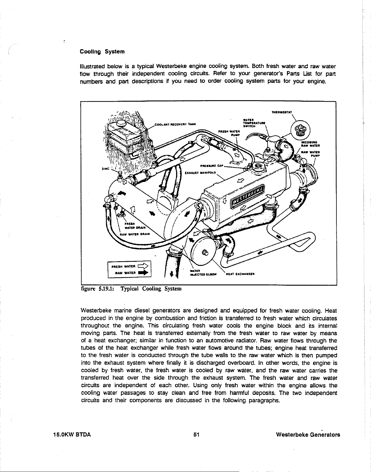
Cooling System
below
is
Illustrated
a typical Westerbeke engine cooling system. Both fresh water and
flow through their independent cooling circuits. Refer to your generator's
numbers and part descriptions
H you need to order cooling system parts for your engine.
'"IUtMOITA1
Parts
raw
water
Ust for part
15.0KW
,,,UH
WATEA
¢'
R
..
WWATU
figure
5.19.1:
Westerbeke marine diesel generators
produced
in
the engine by combustion and friction
throughout the engine. This circulating fresh water
.....
Typical Cooling
System
are
deSigned and equipped for fresh water cooling. Heat
is
transferred to fresh water which circulates
cools the engine block and its internal
moving parts. The heat is transferred externally from the fresh water to raw water by means
of
a heat exchanger; similar
of
tubes
the heat exchanger while fresh water flows around the tubes; engine heat transferred
to the fresh water is conducted through the tube walls to the
into the exhaust system where finally
cooled by fresh water, the fresh water
in
function to
an
automotive radiator.
it
is
discharged overboard.
is
cooled by
raw
water,
Raw
water flows through the
raw
water which
In
other words, the engine is
is
then pumped
and the raw water carries the
transferred heat over the side through the exhaust system. The fresh water and raw water
of
circuits are independent
each other. Using only fresh water within the engine allows the
cooling water passages to stay clean and free from harmful deposits. The two independent
are
circuits and their components
BTDA
discussed
51
in
the following paragraphs.
Westerbeke Generators
Page 54

Coolant from the engine, when heated during engine operation, will expand, lifting the spring-loaded
manifold pressure cap, and enter the recovery tank by way of the hose connecting the recovery
tank to the manifold.
is
When the engine
by the contraction of the engine coolant, allowing some of the coolant in the recovery tank to
be drawn back into the engine's cooling system, free of air and
that the passage (figure 5.19.4) between the
the manifold is clear so coolant can flow in either direction.
shut down and cools, a small check valve in the pressure cap
wtthout
90"
fitting on the mannold and the filler neck
loss.
Periodically check
is
opened
in
FUNCTION
From Coolant Tank
to
Coollnt Tank
figure 5.19.4: Manifold Pressure
OF
COOLANT RETRACTION
MANIFOLD
Cap
PRESSURE
CAP
Westerbeke Generators
52
15.0KWBTDA
Page 55

Fresh Water Circuit
Fresh water is pumped through the engine by a
be~-driven
from the engine. The fresh water coolant circulates through the engine's block absorbing
circulating pump, absorbing heat
heat,
then passes through the thermostat into the exhaust manifold, to the heat exchanger where it
is cooled, and then
circulating pump. When the engine is started cold, external fresh water flow
the closed thermostat (although some fresh water flow
prevent the exhaust manifold from overheating).
is
returned to the engine block through the suction side of the fresh water
is
prevented by
is
bypassed around the thermostat to
As
the engine warms up, the thermostat
gradually opens, allowing the engine's fresh water coolant to flow unrestricted to the external
portion of the cooling system.
Fresh Water Pump Drive Belt Tension
Generator models come equipped with
the engine.
('Out of sight out of mind.' The bett guard
guards that cover over the beit(s)
is
not installed for that purpose.)
on
the front of
be~
Operators are advised that the inspection, service, and maintenance spoken of below should
be followed.
M'ARNiNGI
Never attempt to adjust the drive
operation.
Check Water Pump Belt Drive Tensionl
Excessive water pump drive
beit and reduce the service life of the fresh water pump's bearings.
Excessive slack or the presence of oil
slipping resulting in high operating temperatures.
beWs
tension while the engine
PAOTIONI
be~
tension can cause rapid wear of the
on
the beit can cause beit
is
in
The water pump drive
3/8 inch and no more than 1/2 inch
thumb at the midpoint between the two pulleys on the longest span of the
drive beit should be carried on board
Fresh Water Coolant (Antifreeze) Mixture.
A freshwater and antifreeze mixture should
when it freezes, expands sufficiently to split the heat exchanger and crack the engine block.
A water/antifreeze mixture of proper concentration will prevent freezing.
Use
hard or foul water. Use of hard water or water containing impurities will lead to the collection
of scale in the engine and heat exchanger which will reduce the cooling system's efficiency.
15.0KWBTDA
bett
is
properly adjusted
(10
..
soft water with few impurities, such
if
mm,
the beit can
12
mm)
as the beit
be
deflected no less than
is
depressed with the
beit. A spare
be
used year-round
as
tap water (potable water) or rainwater. Never use
53
in
the cooling system.
Westerbeke Generators
Water,
Page 56

Antifreeze of poor quality or wtthout rust inhibttors will cause corrosion wtthin the cooling system.
Always use antifreeze which is compatible
wtth aluminum cooling system components and is
made by a reliable manufacturer. Never mix different brands of antifreeze. Make sure that the
cooling system of the engine is well cleaned before adding antifreeze. Recommended antifreeze
for year round use
In
order to control the concentration of the mixture. mix the antifreeze and freshwater thoroughly
is
ZEREX or PRESTONE wtth rust inhibttors.
before adding it to the cooling system.
ANTIFREEZE
CONCENTRATION
DATA
Antifreeze
%
13
23
(-5)
23
14
(-to) (-IS)
Concentration
Freezing
Temperature
• F
("
C)
NOTE: An antifreeze concentration should
a temperature which is about 10" F
(5"
30
35
45
5 -4
be
selected on the basis of
C)
lower than the actual
-22
(-20) (-30)
(-40)
60
50
-40 -58
(-58)
atmospheric temperature expected.
the
Filling
1.
Remove the pressure cap from the manifold.
Fresh Water System
2. Pour a clean. antifreeze mixture into the manifold and allow enough time for the coolant
to fill the fresh water cooling system.
3. Start the engine and allow it to come up to its operating temperature. Monttor the coolant
in the manifold and add antifreeze coolant as air is expelled. Once all air is expelled from
the system. fill the manifold to the filler neck and install the pressure cap.
4. Remove the plastic cap from the plastic coolant recovery tank and fill the tank wtth coolant
halfway between the ADD mark and the
5.
Run
the engine and observe the coolant's expansion flow into the plastic recovery tank.
6. Check for leaks between the pressure cap/filler neck and the plastic recovery tank. Stop
the engine and allow it to cool. Coolant should
as the engine's temperature comes down. Check the coolant passage in the filler neck to
ensure
7. Add coolant to the recovery tank. as required. to top off the fresh water coolant system
and periodically check to see that the manifold
cap when the engine is cold.
Westerbeke Generators
MAX
mark.
Replace the plastic cap.
be
drawn back into the cooling system
it
is
open
to
flow. Clean it
wtth
a heavy piece of wire. This
is
full of coolant by removing the pressure
54
is
passage • A".
15.0KW BTDA
Page 57

Thermostat
are
Generally, thermostats
as
closes
the engine's temperature rises and falls. The second type has a bypass mechanism.
of two types.
Usually, this is a disc on the bottom of the thermostat which moves downward to close off
internal bypass passage within the head. Since
n.
The
hole
is
punched through
a bypass to prevent the exhaust manifold from overheating
during the engine's warm-up. Replacement thermostats
One
is
simply a choking device which opens and
1980,
each type of thermostat has a hole
crumt
have this design characteristic.
an
Raw Water Circuit
raw
The
water flow
The pump draws raw water directly from the ocean through the sea cock and
and passes the water to the heat exchanger's
is
created
by
a gear-driven, positive displacement, neoprene impeller pump.
raw
water strainer
raw
water inlet. The
raw
water passes through
the heat exchanger's tubes, from which heat from the fresh water system that circulates around
is
these tubes
absorbed, and then the
overboard through the water-injected wet exhaust system.
the area inside of the heat exchanger where the zinc anode is
raw
water
is
discharged from the cooling system
Be
sure to clean zinc debris from
posnioned as this debris lays
in front of these tube ends and blocks them.
Zinc Anode
is
A zinc anode, or pencil,
located
The purpose of the zinc anode
raw
water cooling
the system. The
or replaced
circuIT,
condITion
as
required. Spare anodes should
thereby reducing the effects of electrolysis on other components of
of the zinc anode should be checked monthly and the anode cleaned
in
the
is
to sacrifice
raw
water cooling
ITseH
be
circuIT
wIThin
the heat exchanger.
to electrolysis action taking place in the
carried on board.
If
the zinc pencil needs replacement, hold
the hex boss into which the zinc pencil
threaded with a wrench while loosening the
anode with another wrench. This prevents
the hex boss from possibly tearing off the
exchanger shell. After removing the zinc,
note the condition of
condition, there
flakes within the exchanger.
of the heat exchanger and clean the inside
of
exchanger end gasket in case the present
one becomes damaged when removing the
end cover. Replace the gasket (refer to your figure 5.25: Zinc Anode
engine model's heat exchanger end gasket
part number), cover, and
15.0KWBTDA
IT.
If
the zinc
are
probably a lot of zinc
all
zinc debris. Always have a spare heat
Remove
is
the end
install a new zinc pencil.
is
in poor
55
NEW
RNOOE
REPLRCE
CLERN
REPlACE
DR
REPlACE
Westerbeke Generators
Page 58

Raw Water Pump
raw
The
water pump is a seff-priming, gear-driven, rotary pump with a non-ferrous housing and
a neoprene impeller. The impeller has flexible vanes which wipe against a curved cam plate
wnhin the impeller housing, producing the pumping action. On no account should this pump
be
run
dry. There should always be a spare impeller and impeller cover gasket aboard
impeller
(raw water)
warrantable and the operator
make sure
Know your pump, know
kn).
Impeller failures occur when lubricant
is
not present. Such failures
is
cautioned to
raw
water flow
is
present at start-up.
ns
location
on
the engine
are
and know how to change the impeller in
Remove the cover and with the
screwdrivers, (figure
5_26),
aid-
of two small
carefully pry the
peller out of the pump. Install the impeller
posnioning the hub shot to align with the
in
the drive shaft. Move the blades to conform
n.
not
im-
by
key
.......
".
(an
to the curved cam plate and push the impeller
into the pump's housing. Replace the gasket
and install the cover.
figure 5.26: Raw Water Pump
BT Generator
en
...
c.u.<
This generator is a four-pole, brushless, self-excited generator which requires only the driving
force of the engine to produce
are
responsible for the seff-exciting feature of this generator. The magnetic field produced
an
AC
causes
voltage to be induced into the related exciter rotor windings during rotation.
Diodes located in the exciter rotor rectify this
AC
output. The copper and laminated iron in the exciter stator
voltage to
DC
and supply it to the windings of
the rotating field. This creates and electromagnetic field which rotates through the windings of
the main stator, inducing
is
connected in parallel to the
the auxiliary windings of the transformer and main stator and
bridge rectifier. The rectifier products a
enabling the generator to produce a rated
an
AC
voltage which
AC
output of the main stator.
is
supplied to a load. A step down transformer
An
AC
voltage
is,
in turn, supplied to a full-wave
DC
voltage to further excite the exciter stator windings,
AC
output. (figure
5_28)
is
produced in
Westerbeke Generators
56
15.0KWBTDA
Page 59

A
+
1-
r---------------~
-:
; t
'AEd:
11
________ : ______
'-
__
---,
:
___
L-----,-t----=_,I
,1-
F.
-.r.:-"C"'RE"."'"L-=1-1"l
I*Lij
G
-'+,
**
I
__
\
YELLDW
+
r--------,
I C I I 0 I
,.--------,
Il,! ; • ;, i
i I 2 I
1
I I 1 I I
I 3 I I
J
t
______
BLA.C'r RED B
Y>
V,..LOW
__
-l_t--
+
!!
J
______
2 :
3-=r""~
L!l!,~!--
___
U
--'
JIILI:
I
J
BLUE
IILUK
•
•
•
3
2
?
A'
T
E
R
M
J
•
A
l
B
l
0
,
,
®
S
T
U
0
G
+
~
______
,--
Fe I
\~
J~
J I
A.
EXCITER
A-1
and
(Selector in
C.
MAIN
STATOR
1.
Main Stator Windings
2.
Main Stator Windings
3. Main Stator Auxiliary Windings
F.
SELECTOR SWITCH
F-1
SWITch
F-2
SWITch
~_~!*
CJe.1!:J:N
'YELLOW
Bl..ACX
STATOR WINDINGS 1 & 2
A-2
Exciter Stator Windings
COMP
in Compound Position
in
Electronic and Compound
PosITion
BUC>
!V"-LOW
~
I
posITion)
I
+
!A.V.Rt
PIUI
Bl
(To
(To
...
(To O ...
b/V.a
.....
/While
Pi
..
,8 T ...
a>..
Berta/YolL.
B.
1.
2.
Block)
Bar)
L~.J;;;:"'----4Y
EXCITER
Auxiliary Windings
Diodes
ROTOR
(6)
......
(
__
r;;'-,"
Black/.hit.
A.V.R. PLUG
(A
Yen·
IT
..
- B -
..
S.ledol'
..
C)
3. Rotating Field Windings
4. Pozi Resistor
D.
COMPOUND TRANSFORMER
1.
Compound Transformer Windings
2.
Compound Transformer Windings
3. Compound Transformer Auxiliary Windngs
with
Vottage/Hertz Connection Bar
G.
BRIDGE
RECTIFIER
WIRING
)
I_hU.
Swncb)
figure 5.28: BT Generator Internal Wirmg Schemabc
Westerbeke Generators
57
15.0KWBTDA
Page 60

No-Load Voltage Adjustment
Vottage adjustment is made with the generator regulation being governed by the compound
transformer.
1.
The selector switch
2.
Operate the generator, apply a moderate load momentarily and remove
output from the generator's 120
be
between 121-124 volts
lIJJill
be
in
the COMP position.
vott
leg(S)
at
61.5 -
62
(220
vott
50
hertz). The no-load vottage should
hertz (222-228 votts at 51.5 -
it.
Note the vottage
52
hertz).
NOTE: The no-load
off. Measure the
transformer.
The
load is removed
the specified range, sut down the engine and adjust the
3.
To raise or lower the vottage, shims of varying thickness (non-conductive material) are
vottage should be adjusted with the engine shut
vottage alter applying a momentary load to excite the
-vottage produced by the generator alter this momentary
is
no-load vottage.
If
this vottage does not fall within
vottage.
placed or removed from under the steel laminated bar on top of the compound transformer.
The material used for shimming should not soften
range. A small reduction in no-load vottage
(1
at temperatures in the 176" F
to 3 votts) can sometimes
be
accomplished
by gently tapping the top of the laminated steel bar to reduce the gap between the existing
shims and the transformer core.
"llu/.hal
Black/Whlh
La.ln.ted
St,,1
...
(80"
C)
figure
15.0KW BTDA
5.29:
Grlln/Whlt_
YoIt'gI/H,rh:
Connection aar
Generator Wiring
and
Adjustments
58
11
.nd
U
Westerbeke Generators
Page 61

Changing The Frequency
1.
Locate the
2.
Refer to (figure 5.29.).
3.
For
50
For
60
Vo~age/Hertz
Hz
operation wire in accordance wtth figure 5.30
Hz
operation wire in accordance
Of
Operation
Connection
Bar.
wtth
figure 5.30
A.
B.
figure
Place
connect
Wire
5.30
Place
connect
this
*6
I
To
AC
terminal
block
A:
50
this
wire
with
to
wire
"5
I
To
terminal
block
Hz Operation
wire
with
to
wire
AC
"5
"3
"6
*2
"1
Vo\lage/Hertz Connection Bar
figure 5.30
Westerbeke Generators
Wire
"6
I I
To
AC
terminal
block
B:
60
Hz
Operation
"5
To
terminal
block
AC
59
*3
Vo\tage/Hertz Connection
Bar
15.0KWBTDA
Page 62

llOV
0 0
"
II~
6 7
,
N
50Hz
0
"
I.,
220V
IIr
0 0
2 0
(Q
•
Kl
~
50HZ
~
7
~
I
L,
120V
60Hz
II
0
2
0
7
•
3 8 3
0
N
Ll
120/240V
~
0
6
0
Ll
60Hz
0
1
9
I
~
111
-
N
figure 5.30.2: BT Generator
NOTE : The frame ground wire must be moved when changing output
vottage or frequency. For making connections to the
AC
Voltage Connections
AC
terminal block,
use 1/4 inch studs that will accept mutti-strand copper wire sized for
the amperage rating from the hot lead connection for terminal ends.
The frame ground wire
is
white or white with a green strip.
It
connects
between the neutral stud and the generator frame.
4.
Frequency is a direct resutt of engine/generator speed: 1
=
50
hertz.
5. To change generator frequency:
A.
Connect the
AC
output leads to the
AC
terminal block (figure 5.30.2). Select the correct
BOO
rpm =
60
hertz; 1500 rpm
ground stud.
B.
Reposition the wire
(figure
C.
Start the engine, monitor vottage and adjust engine no-load speed. Adjust the throttle
arm
5.30
or the throttle stop screw to produce engine speed desired. (figure 5.36.1
A or
on
the vottage/hertz connection bar to correspond to the hertz selected.
5.30
B)
Frequency range:
60
50
hertz:
hertz:
no-load frequency range
no-ioad frequency range
61.5 - 62.0 hertz.
51.5 - 52.0 hertz.
15.0KW BTDA
D.
After the no-load hertz adjustment
In
most cases, if the generator was producing the correct no-ioad vottage
hertz setting,
In
the event
it
would be correct at the changed hertz setting.
it
needs adjustment, adjust the shim thickness under the laminated steel
bar of the transformer. (figure
Frequency range:
60
hertz:
50
hertz:
is
made, the no-load vottage may need to be readjusted
5.29)
no-ioad
vottage, 121-124 votts.
no-load vottage, 111-114 votts.
222-22B volts.
60
at
the previous
Westerbeke Generators
..
Page 63

E.
Load the generator to the rated output amperage corresponding to the frequency selected.
Rated Loaded frequency Range:
60
hertz: full load frequency range 58.5 - 59.0 hertz
50
hertz: full load frequency range 48.5 - 49.0 hertz
Minimum voltage acceptable at full rated output (amps)
60
hertz: 108 votts
50
hertz: 205 votts
Should the vottage drop below the minimum, excttation can be increased to raise this
vottage by repOSitioning connections on the Vottage/Hertz Connection
the two leads from
5.30.7).
(Z)
to M or
(Xl
will change the full load output vottage. (figure
Bar.
Reposttioning
r
,
,
Wire
"6
I
To
AC
terminal
block
5.30.3: Increasing Full Load Output Voltage
figure
#5
I
To
terminal
block
I I
"3
AC
_____
Connect
"2,
or
until
~ePtable
"2
to
wire
-1,
-:3
progressively
output
voltage
limits,
"1
VoltageiHertz Connection Bar
Is
Weslerbeke Generators
NOTE: No·load voltage may be effected requiring readjustment wtth the
nol
compound transformer. Do
for overload conditions being placed
tive-motor type loads). Loss of generator hertz/speed, as a
overload, will cause a drop
use these adjustments to compensate
on
the generator/engine (induc-
in
vottage output.
61
resutt of
15.0KW BTDA
Page 64

Optional Voltage Regulator
An
optional solid-state vottage regulator (board #34410)
generators. When installed, and the
regulator works together with the standard compound transformer regulator to regulate the
generator's
1 exciter windings, and the transformer provides excitation to the group 2 exciter windings.
Installation
1.
The regulator
M4
2.
Connect the 6-prong generator plug to the receptacle on the regulator board.
vottage output.
x 0.7
-mm
is
mounted using existing tapped holes in the generator's case. Use two
screws, each 15 mm long, with lock washers to mount the regulator board.
In
the
regulation switch is moved to the
ELEC
mode, the regulator provides excitation to the group
is
available for use with the
ELEC
BT
series
position, the
(2)
NOTE: The
direction.
3. Before moving the selector switch to the
the generator when
be
should
5.30.2.
4.
Move the selection switch into the
to set
- 52.0 Hertz). The regulator board
and
adjusted down to between 114 - 118 volts following the procedures of paragraph
NO·Load voltage at 120 - 122 votts at 61.5 - 62.0 Hertz. (220 -
should maintain voltage output within
plug
is
keyed to engage the regulator receptacle in one
Check this and insert
in
the COMP position will have to be adjusted. The NO·Load vottage
ELEC
is
operating in parellel with the compound transformer
it
correctly.
ELEC
position the NO·Load vottage produced by
position. Adjust the regulator board potentiometer
224
±5
percent from NO·Load to FULL·Load.
votts at
51.5
15.0KW
BTDA
62
Westerbeke Generators
Page 65

Engine Speed/Generator Hertz Adjustment
Engine speed
62.0 hertz
is
adjusted by poshioning the throttle lever against the adjustable throttle stop screw, lock wiring
is
maintained by the governor mechanism inside the fuel injection pump (61.5 -
at no-load and 58.5 -
59.0
hertz
at
full rated generator output). Engine no-load speed
h at that poshion, and tensioning the throttle stop screw against the throttle lever and securing
h
whh
its lock nut.
Throttle
L.".r._-J~,~e~~~
figure 5.36.1: Engine Speed/Generator Hertz Adjustment
Viewing figure
and moving the throttle lever to the left lowers engine speed (hertz).
Westerbeke Generators
for Diesel Models with Distributor
5.36.1
- Moving the throttle lever to the right increases engine speed (hertz)
63
Injection
Type Injection Pumps
Pump
15.0KW BTDA
Page 66

Shore Power Connections (60 Hertz)
If
the installer connects shore power to the vessel's
of the
figure 5.38
to generator output.
SHORE POWER/OFF/SHIPS
to
the
OFF
posnion. This swnch prevents
GEN
•.
Set the transfer swnch shown in figure 5.37 and
CAUTION
Do Not Connect Generator Output And Shore Power At The Same Tlmel
Damage to the generator can
output
is
make sure
are
connected
not covered under the warranty; n is the installer's responsibility to
all
AC
at
connections are correct,
resu~
the same time. This type of generator damage
AC
circun, this must be done by means
simu~aneous
tl
utiltty shore power and generator
connection of shore power
Generator
]:
..
"
z
51
Shore
-,10
-\@@'
t
N I
,
Power
NOTE:
The
diagram
two-wir.,
three-wlr.
for
the
/ "
~_
, /
,
~r--+-=~~~N
~:::'.:;o~.:;:n"':=--
________ -lll'
shows
120-Volt
system
other
hot
system.
us.
legs.
--,
I
I
I
I
I
I
I
I
I
L..-
.....
'----i~L1
Neutral
connections
dotted
L2
For
line.
Ship's
LOAD
for
Ship-To-Shore
(3
Pole)
PN
32008
40
Amps/Pole
PN
32008
80
Amps/Pole
PN
32010
126
PN
32133
200
Switch
Amps/Pole
Amps/Pole
15,OKWBTDA
figure
5.37:
120V/60Hz
Two
Wire Configuration
64
Westerbeke Generators
Page 67

Switching Shore Power
Shut
Of
Heavy Loads Before Switching Shore To Generator Power
Heavy motor loads should be shut off before switching shore power to
generator power or vice-versa because
switching with heavy
components
Generator
G1
A
( H
to
Generator Power
AC
in
the generator.
NOTE:
The
•
generato,. with •
boat
ICAUTIONI
loads
diagram
two-wire.
system.
vottage surges induced by
may
cause damage to the exciter circuit
shows
120-Volt
connectlona
.ystem
thr
••
-wlre, 120-Volt
from
'or
the
/ "-
4 \
,
:E-t--j--.,
2 V
, /
L---I~L2
L-----I~L1
,
:E-r--+~~~~H
10
~=r=o=:n::::=--_+-
J
Neutral
(White)
____
;;;
i;
..
z
.---"G)
r--+--'<@)
~
j
~
\S2S1H
Shore
v
Power
figure 5.38: 120V/60Hz Three Wire Configuration
-lil'
Ship's
LOAD
Shlp-To-Shor.
(3
Pol.)
PH
32008
40
Amps/Pole
PH
32008
80
Amps/Pole
PH
32010
125
Amps/Pole
PH
32133
200
Amps/Pole
Switch
Westerbeke Generators
65
15.0KW
BTDA
Page 68

Shlp-to-Shore Wiring Connections 220 Volt
BT
Generator
50
Hertz
Generator
Generator
Ground
220V
E9
o 0 0
o
o 0
Terminal
50Hz
0
E:])
L1
Generator/Shore
.:.:
()
co
iii
Block
Switch
...
-,
/
1
3 2 I
,
,_
Ship-To-Shore
,
~
L1
~\
/
.....
PN
PN
PN
PN
Switch
32008
32009
32010
32133
Ship's
LOAD
figure
Note the repositioning of the white ground lead on the terminal block to the generator case,
1S,OKWBTDA
5.39:
l
L1
Shore
220V
220V/50Hz
--
/ "
'-------/-,
(Neutral)
,.......~..:....:.....:...:::....._7
NJ
T
-=
s
, /
.....
_
Shore
Ground
~'""~I
--
••
N
6 I
....
-
Power
50Hz
Two
Wire Configuration
66
Ship's
Ground
Westerbeke Generators
Page 69

Shlp-to-Shore Wiring Connections 110 Volt 50 Hertz
,---
Generator
BT
Generator
....
>----+-\10
Generator
Terminal
110V
50Hz
02
O.
3 8 0
15
70
0
N
Ground
'---I"'i
r-----~--------~3
Block
L1
Ship-To-Shore
Generator/Shore
Switch
/
,
~
'-\\~)
--~~
@/
,
/
PN
PN
PN
PN
Switch
32008
32009
32010
32133
L1
Ship's
LOAD
figure
5.40:
Note the
Westerbeke Generators
repos~ioning
I
L1
Shore
110V
nOV/50Hz
,-
/ "
L-----..J...(:s~)
(Neutral> )
,-----;-{7
, /
6 I
Shore
-
NJ
T
Ground
Power
50Hz
Two
Wire Configuration
of the white ground lead
67
on
the terminal block to the generator case.
N
-
Ground
Ship's
15.0KWBTDA
Page 70

3 Phase BT Generator Wiring
r-------.,
I
I
I
I
I
L.
A
EXCITER
.---+-------,
I I B I
+.
:
1
:1
I
-
I 1
-
I I
L
___
-----
I
.:~:
:: -1* 4
I
I 2
+
_______
....
F
3:
b I
r------,
Ie
:
STATOR
!
rl---!!-
!
:
:
:
:
I
..J
I
I
•
---
•
,
•
,
•
•
I
I
......
·>I55>··--1
:
:
:
:
:
I
I
•
FUSE
8.3"".
FOSE
20
A.
#'
S=OD
-1*
12
A "
e
1l
:
:
'n
B "
:
7 k
...
• L
:
4 B
:
: g
, "
E
+
~
m
~
A.
EXCITER
1. Exciter Stator Windings
C.
MAIN
STATOR
1.
Auxiliary Windings
2-7. Main Stator Windings
3. Auxiliary Windings
E.
DC
CONTROLLER
figure 5.50: 3 Phase BT Internal Wiring Schematic
UDJ
J
REGULATOR
lIE
I
jT
0
~
(DC
Charging Circuit)
(AC
to Regulator)
B.
D.
F.
ROTOR
1. Auxiliary Exciter Windings
2. Diodes (6)
3. Main Rotor Windings
4.
Pozi
Resistor
BRIDGE
VOLTAGE
RECTIFIER
REGULATOR
BOARD
(A
- B -
C)
Westerbeke Generators
68 15.0KW BTDA
Page 71

3 Phase Voltage Regulator Adjustments
And
Protection Circuitry Adjustments
vottage regulator PN#038466
The
ternator performacne.
operating conditions that could be detrimental to the
It
is equipped with complete protection circuitry to guard against
is
of
an
advanced design which ensures optimum
~j
o 0
:l
'c
C
C
I
~
0
DoD
n
1"1"
Paten
LED'S
Red
Green
Yellow
tiolTIeters
Hz.
Axnp.
Stab.
Volt
AC
atternator.
IV
AC
al-
~]~6
Il
~'
;;'
~
~J
@
~J
mr©
0
5
4
3
2
1
0
B
+
-
J80
BII:.
figure 5.60.: BT 3 Phase Voltage Regulator
15,OKW BTDA
69
Westerbeke Generators
Page 72

Adjustments To 3 Phase Regulator
Volts
This potentiometer is used to adjust output
output
vo~age
and from
Stability
should
powe~
factor 1.0 -
be
held
at
± 1 % from a no load condition
O.B
with engine drive speed variations of up to
vo~age.
At proper engine operating speed, the
to
full rated generator output
-6%.
This potentiometer permits variatiol) of the regulator's response to generator load changes so
as to limit overcompensation and obtain a minimum recovery time to the normal vottage output.
Amp - Hertz
are
These two adjustments
regulator that are indicated by the illumination of a colored
1.
Delayed overload protection (yellow
2.
Low speed protection (red
Each system has
an
used in conjunction with the two protection circuits in the vottage
LED.
LED)
LED)
intervention threshold which
can
be adjusted using a potentiometer. Each
of the two circuits reduces excitor vottage to safeguard the excitor windings and prevent
overheating.
The overload protection system has a delay which permits temporary overloading of the generator
during times such
has a third
LED
the regulator with the generator.
Westerbeke Generators
as
motor stan up or other similar load surge demands. The regulator also
(green), that glows during generator operation to indicate correct operation of
70
15.0KWBTDA
Page 73

Regulator Sensing 3 Phase
WYE
and Delta Configurations
I
\
\
PARALLEL WYE (STAR)
10
12
8
4
1
L-L
208
L-H
120
L"L
!SID VAC
LooN
110
SERIES DELTA
L-L
L2,L3-H
L-L
L2.L3-H
240YAC
120YAC
nOYAe
HOYAt
3,
,.
39
"
9
5
1
60
60HZ
50
50
HZ
HZ
HZ
11
6
2 3
VAC
VAt
VAC
The
7
:Sf
eo
" eo
:til
50
'9
50
9
5
1
HZ
HZ
HZ
HZ
L1
L2
L3
N
1
SERIES WYE
12
8 6
4
L-L
460
L
-N
26$
L-l
380
LooN
220
(STAR)
11
10
a:::::D
7
a:::::D
2 3
a:::::D
VAC
3,
VAC " 60
VAC
39
VAC " 50HZ
60HZ
50HZ
~
V
~
V
1
~
HZ
L1
L2
Q)
L3
N
regulator is equipped with seven numbered terminals and related brass jumpers. Figure
5.70.1 shows the connection points and jumpers for the 3 phase configuration of the generator.
The
sensing leads connect between pin
#2
and
#0
on
the vonage regulator board.
NOTE: Series
Dena
board between terminal
requires the installation of a jumper
#1
Band
and pin
O.
#2
on
the
AC
terminal block and connection
on
the regulator
L1
L2
L3
N
15.0KWBTDA
170-27DV.rv
+
EXCITE~
--~
--~
~
I SOH:.
D
figure 5.70.2: Voltage Regulator - 3 Phase
71
D
80-180V.,...,
--~
180Hz.
--~
Westerbeke Generators
Page 74

Motor Starting Requirements
an
The power required to start
it
keep
others. Split-phase
than other types. They
machines, or where loads
tools. Because they require 5 to 7 times
should
generator. Capacitor and repulsion-induction motors require from 2 to 4 times as much
current to start
connected to
require more current than
In
loads will
running after
be
avoided, whenever possible,
it.
general, the current required to start 115-volt motors connected to medium starting
be
approximately as follows:
it
is
started. Some motors require much more current to start than
(AC)
motors require more current to start, under similar Circumstances,
are
as
to
run.
An
electric motor connected to
electric motor
commonly used on easy-starting loads, such as washing
are
applied after the motor
if
The current required to start any motor varies with the load
a_
motor to which no load
is
considerably more than is required to
is
started, such as small power
as
much current to start
the electric motor
an
air compressor, for example, will
is
connected.
as
to
run,
their use
is
to be driven by a small
MOTOR
figure
6.0.2:
NOTE:
for some small motors than for larger ones. The reason for this
the hardest starting types (split-phase)
Because the heavy surge of current needed for starting motors
instant, the generator will not
few seconds.
and, H possible, reduce the load
loads
SIZE
(HP)
110
1/4
1/"
1/,
"/4
1
Startmg Loads
In
the above table the maximum "Amps for Starting"
be
damaged H
If
difficulty
is
experienced
AMPS FOR AMPS FOR
RUNNING
(Amperes) (Amperes)
3.2
4.6 9.2 to
5.2
I."
lU."
1;;
are
not made
IT
can bring the motor up to speed in a
in
starting motors, turn off
on
the electric motor.
in
larger sizes.
STARTING
6.4
to 22.4'
10.4
to
14.4 to
"U.4
to 4U.1l
,0
to
is
more
is
that
is
required for only
all
other electrical
32.2'
{".Il·
"!!."
52
an
Westerbeke Generators
72
15.0KWBTDA
Page 75

Required Operating Parameters
Although individual units may vary slightly, the normal voltage and frequency of typical
engine-driven generators described
Run
the generator
loaded to
Load
tts
at
first with no load applied, then at haff the generator's capacity, and finally
full capactty
4 ",ole
as
Speed Frequency
in
this manual
are
shown below.
indicated on the generator's data plate.
vonage
120V (110)
Applied (rpm) (Hertz)
None
Half 1800
Full
figure
7_0.1:
Voltage
The output voltage should
and the appliances
and
1830
(1530)
(1500)
1755
(1455)
Frequency
tt
supplies.
-
be
checked periodically to ensure proper operation of the generator
62
(52)
60
(50)
59
(49)
122 240
(112) (224)
120
(110) (220)
110
(100)
60-(50-)hertz
vonage
240V(220)
240
220
(200)
If
an
AC
voltmeter or ammeter
is
not installed to monitor voltage and load, check with a portable
meter.
NOTE: When the vessel in which the generator
equipment of 120 volts only,
AC
terminal block
be
configured to provide one 120 volt
it
is
for the vessel's distribution panel. This will ensure good motor starting
response from the generator.
Preventive Maintenance (Generator)
1.
Keep the generator clean, dry and well-ventilated.
2.
Make
sure
all
connections
are
clean and tight and that cables carrying
properly supported and protected against chafing.
3.
The rear armature bearing
If
the bearing becomes rough or noisy, replace
4.
Do
not overload.
5.
On
starting
up,
allow the engine to warm up with no load. Then apply the load
is
lubricated and sealed; therefore, no maintenance
is
installed contains
AC
recommended that the generator's
AC
hot leg
AC
n.
vo~age
is
required.
in
steps.
are
15.0KW BTDA
73
Westerbeke Generators
Page 76

Troubleshooting
Engine Troubleshooting
tables which follow indicate troubleshooting procedures based upon certain problem
The
indicators, the probable causes of the problems, and the recommendations to overcome
these problems.
Note that the engine's
manual reset circuit breaker located
forward of the generator's
is
de-energized when the emergency
control panel
PREHEAT switch
panel indications, fuel not
no
solenoid, electric
and preheat solenoid not
energized. tripped. trips again, check preheat
~TART
no starter engagement.
is
depressed. Shutting down the engine.
Problem Probable Cause
switch
is
control system (electrical system) is protected by a 20-Ampere
on
a bracket on the right side of the engine, just
Elnd
plate.
The
fuel solenoid mounted in the injection pump
is
depressed:
fuel pump
depressed:
STOP
1.
Battery
20-Amp
2.
1.
Connection to solenoid
faulty.
Faulty
2.
Faulty solenoid.
3.
switch located on the rear of the engine
Verification/Remedy
on.
START
SWITch
circuIT
breaker
SWITch.
1.
Check switch and/or
battery connections.
2.
Reset breaker; if breaker
solenoid circuit and check
circuIT
1.
Check connection.
2.
Check switch
for shorts to ground.
3. Check that
present at starter solenoid
connection.
12
WITh
Votts
ohmmeter
are
START
panel indications
start solenoid
fuel solenoid not
functioning.
Westerbeke Generators
switch
is
depressed:
OK;
OK;
4.
Loose battery
connection.
Low
5.
1.
2.
batteries.
Poor
connections to
fuel solenoid.
Defective fuel solenoid.
74
4.
Check battery connection.
5.
Check battery charge state.
1.
Check connections.
2.
Check that
present
on the injection pump.
Remove solenoid
pump and test separately.
12
Votts
at
the fuel solenoid
from
15.0KWBTDA
are
the
Page 77

Problem
No ignition: cranks,
but does not start;
fuel solenoid energized.
Failure to stop.
Probable Cause
1.
F aully fueling system.
1.
STOP
switch failure.
2.
Fuel solenoid
will not de-energize.
Verification/Remedy
1.
Check for fuel to generator
engine.
2.
Check for air in fuel system.
Bleed point on filter.
3.
Fuel lift pump faully.
I ers c
ogge.
ep
filters and allow system to
seH-bleed
only the
1.
Stop engine by depressing
emergency
by depressing
PREHEAT
STOP
switch
engine or manually moving
lever
the shut off
on
injection pump side. Test
switch with ohmmeter.
2a.
Manually unplug the 12 Volt
connection to the solenoid
at the injection pump.
ac"
switch.)
on
the
Engine stops.
1.
Low oil pressure or
overheated.
2.
Low
oil
pressure
switch opens.
3. High temperature
switchs open at too
low a temperature.
(water temperature)
(exhaust temperature)
4.
2D-Amp
circuit breaker
tripping.
2b. Loosen high pressure
injector
lines at each
injector.
Beware of
1.
Check
and sea water
2.
Check for satisfactory
fuel spray.
oil
level;
check fresh
cooling.
operation with switch
bypassed.
Check with ohmmeter.
3. Check for satisfactory
operation with switch
bypassed. Check with
ohmmeter.
4. Check for high
DC
amperage draw during
operation. Ensure switch
not overly sensitive to heat
which
would cause tripping.
an
is
15.0KW
BTDA
75
Westerbeke Generators
Page 78

"roo,em
rooaDle \,;ause Verttlc8tton/nemeay
..
Engine stops.
(cont.)
Battery not charging.
Battery runs down.
Emergency
5.
switch or
in
panel defective,
opening fuel
solenoid
Switches and/or wiring.
6.
STOP
STOP
run
circuIT.
-
1.
A~ernator
Oil
1.
D.C.
pressure switch.
SWITch
Check operation
5.
WITh
an ohmmeter.
Inspect
6.
all
of
wiring for
switch
short circuits and loose
connections.
Inspect
switches for proper
operation.
1
a.
Check drive
Be
sure
be~
tension.
a~ernator
turns
freely.
b.
Check for loose connections.
1
c.
Check output
1
1
d.
Ensure 12 Volts are present
at
the R terminal
Observe if gauges and
1.
panel lights
when engine
WITh
are
activated
is
not running.
vo~meter.
Test the oil pressure switch.
Weslerbeke Generators
High resistance leak
2.
2.
to ground. sensitive
3.
Low
Alternator.
4.
resistance
76
leak.
3. Check
4.
Check wiring. Insert
(0-.25
Amp)
meter
in
battery
start engine.)
lines.
(Do
Remove
not
connections and replace
is
all
wires for
located.
rise
to locate
at
after short
temperature
fau~.
the
Disconnect alternator
output, after a good battery
charging.
remove
If
leakage stops,
a~ernator
and
bench test.
Repair or replace.
15.0KWBTDA
Page 79

Generator Troubleshooting
complete and illustrated text
A
Technical Manual which
the
Troubleshooting Water Temperature and
If
the gauge reading
panel
is
energized, the first step
the Negative
Assuming there
following steps.
the
1.
Disconnect the sender wire
normal reading for this situation.
2.
Disconnect the ground connection at the gauge and see
which
(B-)
is
the normal reading for this situation.
is
other than what
terminals of the gauge.
are
12
votts as required, leave the instrument panel energized and perform
on
troubleshooting the
is
available through your local dealer.
011
Pressure Gauges
is
normally indicated by the gauge when the instrument
is
to check for 12 votts
at
the gauge and see
BT
series of generators
DC
between the ignition (B+) and
ff
the gauge reads zero, which
ff
the gauge reads full scale,
is
furnished in
is
the
If both of the above gauge tests
either with the conductor from the sender to the gauge or with the sender.
lies
If
either of the above gauge tests
be
replaced.
Assuming the gauge
the gauge for continuity.
Check that the engine
terminals and
ground side will not necessarily
ff
is
OK,
block
the battery
check the conductor from the sender to the sender terminal
is
is
are
positive, the gauge
are
negative, the gauge
connected to the ground. Some starters
connected to the starter (both plus and minus terminals), the
be
connected to the block.
is
undoubtedly
is
probably defective and should
OK
and the problem
have
isolated ground
at
15.0KW BTDA
77
Westerbeke Generators
Page 80

PERIODIC MAINTENANCE and ADJUSTMENTS
This section contains a scheduled preventive maintenance program and several adjustment
9.3 procedures the owner/operator can perform
tools and instruments.
9.3.1
Preventive Maintenance
in
9.3.2 Perform the preventive maintenance
accordance with the schedules listed in the following
paragraphs. Adherence to these schedules will ensure the equipment
~
will
possible condition and that
(*) are recommended to be. performed
perform to expectations. Those items marked by an asterisk
by
Dally (before each use)
1.
Check the oil sump
Do
not overfill
2.
Check the coolant level in the plastic recovery tank. Maintain this level
level marked
ADD.
level.
Maintain the oil level
Periodically, check the coolant
to the top of the filler neck.
w~hout
the
benef~
of sophisticated and expensive
is
maintained in the best
an authorized dealer or distributor.
at
or near upper level mark on dipstick.
level
in the manifold.
at
or above the
It
should be filled
3.
Visually inspect the unit; check for loose
betts,
chafed or broken wires, loose brackets and
fittings, damaged hoses, loose clamps, and other equipment not properly secured.
4.
Check the fuel supply.
5.
Check the primary filter/water separator. Drain and service as required.
separator is optional, but strongly recommended
engine from fuel contaminants
6.
Check the generator's gauges or lights for proper oil pressure, operating temperature,
staning battery charging
is
engine
7.
Check the generator's output meters (when installed) for proper
operating.
Fill
tank(s) with a good grade of No. 2 diesel fuel.
as
damage to fuel equipment
is
not warrantable.)
vottage and
pos~ive
fuel pressure to injection pump once the
(A
primary fitter/water
AC
voltage and output
frequency.
Monthly
1.
Check the condition of the zinc anode in the heat exchanger's sea water
Keep
replace the anode, as required.
the area inside the heat exchanger clean of zinc
circu~.
anode debris.
2.
Check siphon break operation when insttalled. Clean or replace
as
needed.
on
the
Clean or
15.0KW BTDA
78
Westerbeke Generators
Page 81

Servicing After Initial 50 Hours of Operation
1.
Change the engine's lubrication oil and oil
2.
Replace the fuel filter element
filter element and clean the
in
the engine-mounted secondary fuel
fi~er/water
fi~er.
sedimentor, n a separator has been installed, and
n the model type permhs cleaning.
*3. Torque the cylinder head hold down bolts.
*4. Adjust valve clearances.
5.
Adjust the water pump drive
6.
Check electrical connections at the generator. Ensure they
chaffe.
7.
Adjust the engine's no-load speed, n required (hertz) and make any
adjustments that maybe needed.
adjustments during or after the generator's break-in.
be~
tension, n required.
Please
note that these adjustments are not warrantable
fi~er.
Change the fuel
are
tight and not subject to
vo~age
regulator
Servicing After Every
1.
Change the engine's lubrication oil and
2.
Adjust the water pump drive
Servicing After Every
1.
Replace the fuel filter element in the engine-mounted secondary fuel filter.
Servicing After Every
100 Hours of Operation
oil
filter.
be~
tension, n required.
250 Hours of Operation
500 Hours of Operation
*1. Torque the cylinder head bolts.
*2. Adjust the valve clearances.
3.
Drain, flush, and refill the fresh water cooling system. A block drain plug is found
right side of the engine block adjustment to the backplate. Drain pet cocks are located
on
the lower side of the heat exchanger.
on
the
*4. Check the condition of the starter motor drive pinion; lubricate the pinion.
Westerbeke Generators
79
15.0KWBTDA
Page 82

5.
Check the resistance of the glow plugs (.4 to
engine and
glowplug
reinstalling.
6.
Check the internal condition of the water injected exhaust elbow. Inspect the exhaust and
water passages. Remove any carbon and/or corrosion build
required.
7.
Check the
housing. Replace worn parts,
them, as needed.
clean the carbon build up from the pencil end. Apply 12-Votts
to
ensure proper functioning. Use antiseize compound on the threads when
raw
water pump for internal wear. Examine the pump's cover,
as
needed. Check for leaks at seals or gaskets and repair
.6
ohm). Remove the glow plugs from the
DC
across the
up.
Clean or replace
cam,
and internal
as
NOTE:
competent mechanic.
Servicing After Every
of Operation
*1. Remove and check
Injector spray pressure:
1920 psi ± 71psi
(135
Eliminate undesirable injection
conditions including after dripping.
*2. Check the engine's compression
pressure. Remove each
and check each
pression pressure. The engine's cranking speed
Standard
427 psi
(30
kg/cm2)
Items highlighted by
800 Hours
fuel injectors.
2
kg/cm
±
5.0
kg/cm
cylinder's com-
2
glow plug figure
an
)
Minimum
384
psi
(27
kg/cm2) (Maximum difference between cylinders:
asterisk
9.8.1:
(*)
should be performed by a
Fuel
Injector Spray Pattern
is
at
280
rpm.
43 psi [3.0 kg/cm2])
POOR
GOOD
DC
*3. Check the
*4. Check the tightness of bolts, nuts, and clamps. Check
clean connections and that no chaffing of the wires
15.0KW BTDA 80 Westerbeke Generators
Charging Circuit for proper operation.
AC
is
occuring.
and
DC
wiring to ensure tight
Page 83

Servicing After Every 1000 Hours of Operation
Remove,
should be able to clean and test the heat exchanger.)
Torquing Cylinder Head Bolts
clean, and pressure test the primary heat exchanger.
NOTE: Operating in
exchanger cleaning
silty and/or tropical waters may require that a heat
be
performed more olten than every 1000 hours.
.
Tighten the cylinder head
Make sure the engine
~
then tighten
in the sequence. Tighten the
between
bo~s
is
cold when this
80
to
85
Ib-It
RS
according to the sequence shown in the illustration below.
is
done, and loosen one head bold one-han turn and
(11.0
to 11.7 kgim). Then proceed to the next head
(rocker cover stud) securely.
4
1
5
(A
local automotive radiator shop
boH
15
<erentl
figure 9.10.1: Cylinder Head Bolt Pattern
11
2
Westerbeke Generators
81
15.0KW BTDA
Page 84

Valve Clearance Adjustment
NOTE: Retorque the cylinder head botts before adjusting the engine's
valves.
Adjust the valve clearance when the engine
cylinder in the firing order of the engine. Tighten the cylinder head
by
bolts to the specified torque before adjusting the valves.
Pull
off the air breather
the
pipe from
rocker
cover, and take off the
rocker cover
botts and
the rocker cover to ex-
pose the rocker shaft and
valve assembly.
I
CAUTION
I
Adjust valves properly
is
'Wb.en
No. 1 c,.llnder
1.
cold. Valves are adjusted
at.
top
d.ead
cent.er
Position the
TOP Dead
at
(TOC)
stroke and adjust the
1,
2,
3 and 6 valves (see
the
illustration
on
ITS
No.
1 piston
Center
compression
#
to
the
right).
PosITion
at
TOC
the
of
No.
its
4 piston
compres-
sion stroke and adjust
the
#
4,
5,
7 and 8 val- figure
ves.
The valves are num-
bered 1 to 8 from the
front of the engine to the
back.
Adjust
each
valve's
clearance by inserting a
0.012 inch (0.3 mm)
feeler gauge between the
rocker arm and the
stem.
Make
sure to ad-
all
just
inches (0.3
engine
valves to 0.012
mm)
is
cold.
valve
while the
9.11.4:
I
L_I
Valve
When
No.4-cylinder
Adjustment
Sequence
1.
at
t.op
st.", C"p
dead
oenter
15.0KW
BTDA
figure
9.11.6:
82
Westerbeke Generators
Page 85

Injection Pump Timing
is
This Information
found in the engine technical manual and should only be performed
competent mechanic familiar with Diesel
Adjustments (Generator)
KiKi
injection equipment.
by
a
Once the diesel generator set has been placed
for engine speed (hertz) during the engine's break-in period (first
A no-load voltage adjustment may also
in
operation, there may be adjustments required
50
hours) or after this period.
be
required in conjunction with the engine's speed
adjustment. These are not warrantable adjustments as they relate to normal break-in and
maintenance.
!CAUTIONI
Switch
When starting the generator,
should be
sw~ched
cold climates, starts to warm
caused by unanticipated operation of
cold engine from stalling.
Off
AC
Load Before Starting Generator
all
AC
loads, especially large motors,
off until the engine has come up to speed and, in
up.
This precaution will prevent damage
AC
machinery and will prevent a
Westerbeke Generators
83
15.0KW
BTDA
Page 86

Table
Of
Standard Hardware
Tightening
Torques
Unless stated otherwise for a specific assembly, use the following torque values when tightening
standard hardware.
..
'3rade
4T
6mm
Ilmm
1
Omm
lUmm
12mm
l"mm
12mm
13mm
14mm
14mm
16mm
bmm
lIcn
bo~
head/nut 1.0 2.9 -
Don
bo~
head/nut 1.25 13.7 - 22.4
Don
bo~
~,,,ut
.«0
.!>
1.25
(ISO)
0011
bo~
DOlt
bo~
Don
bo~
oOIT
head/nut
,"
,"
"
1.75
1.5 32.5 - 50.6
1.5
2.U
1.5
"u
lo-n
5.1
1.«
- 11.0
3.~
-
«.7
25.3
"".~ -3~.1:>
21.7
36.2
34.U
39.B
36.2
- 57.9
-
"".1
54.2 79.6
"'.4
-
(1.(
Kg-m
0.4 - 0.7
U
-
1."
3.1
1.9
1.B
-
".U
3.5
- 5.5
3."
- 0.0
3.0 5.0
4."
5.0 -
.U
-
B.O
4.7 - 7.7
7.5 -
11.0
(.1 -
lU
. .,
~rade
6T
6mm bolt head/nut
Ilmn
10mm
lUmm
0011
bo~
ooIT
~
I.
12mm bolt head/nut 1.25
,,,mm
DOll
neaa/nUl
12mm
~rade
6mm
I:>mm
1
lUmn
7T,
8T and 8.8
bo~
0011
Omm
bo~
head/nut
head/nut 1.0
bolt
""aUI
nut 1.25
0011
~
12mm bolt head/nut 1.25
l«mn
Dan
12mm bolt head/nut 1.75
13mm
14mm
14mn
16mm
10mn
Don
bo~
,,~gvo
DOll
~m~
bo~
""aUI
~Oll
neaa/n~
"ut
nut
1.0 4.3 - 6.5
1
U.I:>
-
-
-
-
-
-
•
".~
3UA
"U.O
49.2
B.7
"'.f
39.B
;;I.t
75.9
0".
61.5
1l0.1l
.""
1.25 21.7 32.5
1."
(ISO)
1."
1
"."
36.2 - 57.9
"0.«
1.75 34.7
5.B
1.""
14."·
2B.9
1.0
(ISO)
1.0
"b.1:>
54.2 •
50.6 -
43.4
1.5 .57.H -
0.6 -
1."
3.0
".f
5.0
".U -
4.B
O.B
2.U·
4.0·
3.f·
7.5
6.0
I:>.U • ''',U
I.U·
0.9
- 2.2
4.5
-
4."
B.O
(.U
6.B
- 1.2
3.U
5.5
5.2
10.5
~.U
B.5
1.5 72.3 108.5 10.0 • 15.0
".U
1.5
".U
.,1>.1 • H; .3
10B.5 166.4
lUl.;;
• 1
,,~.
H.5
• 14.0
15.0 - 23.0
14.U
.
~.U
15.0KW BTDA
B4
Westerbeke
Generators
Page 87

Grade 5 capscrew
!'lIen
lo-n
K~-m
1/4
UNC
1/"
UN.-
5/16
UNC
"flO
UN~
3/8
UNC
"It!
UNI
7/16
utilc
fllb
UN.-
1/2
UNC
1/2
UN~
~ngine
pylinder
~yllnaer
ponnecting rod cap
JVlaln
~amshaft
",amsn a gear
die gear
nlecllOn pump anve
"'ocker arm assembly
Imlng gear case
iming gear cover
Hear
Oil
UII
Water pump
c..;ranKsnan
emperature gauge unit
UI
f3low plug
nlectlon nozzle
njection pipe flare nut
ntaKe
xhaust manifold
"xhaust elbow (to exhaust manifold)
ClaCK
njector spray Pressure
pylinder Compression Pressure
Tightening Torque Table
head
neaa cover
oeannQ
Oli
pan
pipe
pressure
mam
plate
cap
thrust plate
seal cap
(UII
pump)
ulley
sWltcn
010
Qear
9.0 -
11.0
18.0 -20.0
<!l.U
28.0 -
"u.u -"".u
44.0 -
ou.u
68.0 - 73.0
/".u
Ft-IO I\g-m
80 -
50
IlU
12
""
17
ai
80
1,
12
11
12
145
12
18 -
1,
12
,4
135
30
85
;j
"
54
-
1:l5
17
-
"1
23
-
51
- 85 11.0
11
17
15
-
5 -
0
9 -
!oj
7 -
9
9
17
-
1 III
13
-
1~
11
,
22
1
17
-
,,,,
+ 5 kg/cm
kg/m2 at
2
200
11.0
-
I".U
<!;;.U
-
33.0
49.0
-
OO.U
t!u.u
-
+
(1920
rpm (427
71/0
psO
11.0
'I.U
20.0
psO
u."
6.9
1.6
b."
2.3
4.u
1.b
1.6
1.5
0.7
U.t!
1.6
1.2
1.2
1.0
1.0
2.5
1.b
1.6
,"
1.2 -
1.0 - .t!
2.5 -
-
<!.9
3.7 -
4.
-
6.1
-
0.9
-
9.4 - 10.1
o
lU.
11.7
-
U.4"
7.5
-
,
1./
2.4
-
t.U
3.2
-
.U
11.7
-
<!.4
2.4
-
<!.U
-
1.2
-
1.,
2.4
-
,,,.u
1.8
-
,
.Il
-
1.5
-
,.4
3.0
-
2.4
2.4
-
"".U
1.5
2.8
".,
4.6
4.1l
6.8
f.O
11.1
Westerbeke Generators
85
15.0KWBTDA
Page 88

LAY-UP
General
rely
Many owners
for lay-up during the off-season or for long periods of inactivity.
lay-up preparation themselves.
on their boatyards to prepare their craft, including engines and generators,
AND RECOMMISSIONING
Others prefer to accomplish
The procedures which follow
as
or to use
These procedures should afford your engine protection during a lay-up and also help familiarize
you with the maintenance
If you have any questions regarding lay-up procedures, call your local servicing dealer;
be
more than willing to provide assistance.
Fresh Water
50·50 solution of antifreeze and fresh water is recommended for use in the fresh water
A
cooling system
depending on the area's winter climate. Check the solution to make sure the antifreeze protection
is
adequate.
Should more antifreeze
add a more concentrated mixture.
mixture of the
solution's strength.
Lubrication System
WITh
the engine
oil
filter. (Place some paper towels and a plastic bag around the filter to catch the oil during
ITS
removal.)
a check list
Cooling System
at
all
times. This solution may require a higher concentration of antffreeze,
antffreeze concentration throughout the cooling system. Now recheck the antifreeze
warm,
will allow you to perform your own lay-up and recommissioning,
ff
others do the procedures.
n~eds
be
drain
of your engine.
needed, drain
Operate the engine to ensure a complete circulation and
all
the lubricating oil from the oil sump. Remove and replace the
an
appropriate amount from the engine block and
he
will
When installing the new oil filter,
gasket at the base of the filter.
(Refer to the
of
no leaks.
15.0KW BTDA
CC
be
sure to apply a small amount of
Fill
the sump
"System Specifications" section of this manual.)
or
CD.
Run
the generator and check for proper oil pressure and make
Remove
Do
not
leave
the engine's old lubricating oil in the sump over the lay-up
oil
period. Lubricating
harmful chemicals which can reduce the life of your engine's internal
parts.
and combustion
WITh
I
CAUTION
011
During Lay-Up
the correct amount of oil for your engine.
Use
I
depOSITS
combine to produce
86
oil
an oil with
Westerbeke Generators
on the rubber sealing
an
API
specification
sure
there are
Page 89

Fuel System
Top off your fuel tanks with
be added
additives used are
the
clean the separator sediment bowl.
Change the fuel filter element on the engine and bleed the fuel system, as needed. Start the
engine and
Check for any leaks that may have been created in the fuel system during this servicing,
correcting them as needed. Operating the engine for
of the treated
Raw Water
Close
the end of this hose into a 5-gallon bucket of clean fresh water. Before starting the engine,
check the zinc anode found in the primary heat exchanger on the engine and
as
a
anode
Start
the bucket
stronger than needed for winter freeze protection in your area.
at
this time to control algae and condaion the fuel. Care should
compatible wah the primary fiher/water separator used in the system. Change
element in your primary fuel Mer/water separator, H the fuel system contains
allow it to run for 5 - 10 minutes to make sure no air
fuel through the injection equipment
Circuit
the through-hull sea cock.
required, and also clean any zinc debris from inside the heat exchanger where the zinc
is
located. Clean the raw water strainer, H one
the engine and allow the raw water pump to draw fresh water through the system. When
is
empty, stop the engine and refill the bucket with
No.2
diesel fuel.
Remove
the
Fuel
additives such as Sta-Bil and BioBor should
be
taken that the
is
left
in
the fuel system.
5-10
minutes will help allow movement
on
the engine
raw
water intake hose from the sea cock. Place
clean or replace
is
installed, in the inside of the hull.
an
antifreeze solution slightly
one,
and
Start the engine and allow all of this mixture to
the bucket
circuit from freezing during the winter
Remove the
catch it in a bucket). Examine the
gasket.
cover and gasket.
Intake Manifold and Through-Hull Exhaust
Place a clean cloth, lightly soaked in lubricating
block the opening.
an
and
Make a note to remove the cloth prior to start-up. The through-hull exhaust port can be blocked
in the same manner.
is
empty, stop the engine. This antifreeze mixture should protect the
lay-up,
impeller from your
Do
not replace the impeller (into the pump) until recommissioning, but replace the
Do
not shove the cloth out of sight.
attempt is made to start the engine, you may need the assistance of a servicing dealer.)
raw
water pump (some antifreeze mixture will accompany
impeller. Acquire a replacement,
be
drawn through the
as
well
as
providing corrosion protection.
oil,
in the opening of the intake manifold to
(If
raw
water system. Once
if
needed, and a cover
it
is
not visible at recommissioning,
raw
water
it,
so
Westerbeke Generators
87
15.0KWBTDA
Page 90

Generator End
Remove the louvered cover on the generator end. Check
block
and those running to the bridge
connections appear corroded, they
all
AC
leads are properly cleaned and reconnected. Make sure
rectHier
making sure they are secure. Should these
should be removed, cleaned, and reconnected. Make sure
all
wire connections on the
all
AC
leads
AC
are
terminal
properly
supported and not chafing as they exit the generator housing.
Starter
Molor
Lubrication and cleaning of the starter drive pinion is advisable, H access to the starter permits
its easy
removal. Make sure the battery connections
are
shut off before attempting to remove
the starter. Take care in properly replacing any electrical connections removed from the starter.
Cylinder Lubrication
It
is
not necessary to remove the glow plugs from the cylinder head to squirt light lubricating
oil
into the cylinders for the few months of normal lay-up. However,
lay-up
light oil
period (12 months or more),
in
the cylinders will prevent the piston rings from sticking to the cylinder walls. Make
we
recommended that this procedure be performed. The
ff
you anticipate a longer
sure you apply a light coat of anti-sieze on the threads of the glow plugs when reinstalling.
Spares
Lay-up time provides a good opportunity to inspect your Westerbeke engine
items such as drive
order items not
zinc anodes. Refer to the
Batteries
If
batteries are to be left on board during the lay-up period, make sure they are fully charged,
and
batteries will not remain fully charged, or that they will be subjected to severe environmental
conditions, remove the batteries and store them in a warmer, more compatible environment.
15.0KWBTDA
be~s
or coolant hoses need replacement. Check your basic spares kit and
on
hand, or replace those items used during the lay-up, such
"SPARE
PARTS"
section of this manual.
will remain that way, to prevent them from freezing.
88
to
see
ff
external
as
Mers
If
there exists any doubt that the
Westerbeke Generators
and
Page 91

Recommissioning
The recommissioning of your Westerbeke engine after a seasonal lay-up generally follows the
same procedures as those presented in the "Preparations For Starting" section regarding
preparation for starting and normal starts. However, some of the lay-up procedures will need
to be counteracted before starting the engine.
1.
Remove the oil-soaked cloths from the intake manifold and from the through-hull exhaust
port.
2. Remove the
water pump impeller removed- during lay-up (or replacement,
water pump cover
3. Reinstall the batteries that were removed during the lay-up, and reconnect the battery
cables, making sure the terminals are clean and that the connections are tight. Check to
make sure that the batteries
4. Check the condition of the zinc anode
anode as needed. Note that
from the
self-flush
an
end of season or recommissioning service to inspect the area that the zinc
in
the heat exchanger and clear any and
at
raw
water pump cover and gasket and discard the old gasket. Install the
IT
required). Install the raw
wtth a new cover gasket.
are
fully-charged.
I
WARNING
Wear rubber gloves, a rubber apron, and eye protection when servicing
batteries. Lead acid batteries
be
which can
or pipe. Do not smoke or allow
serviced.
electrical arcing during servicing.
raw
water coolant system. When the engine
in
a short period of time with no adverse affects. It
igntted
Shut off
by
all
electrical equipment in the vicintty to prevent
it
is
emtt
electrical arcing' or a lighted cigarette, cigar,
an
in
not necessary to flush the antifreeze/fresh water solution
I
hydrogen, a highly-explosive gas,
open flame near the battery being
the
raw
water circutt and clean or replace the
is
put into operation, the system will
is
adviseable to, as either
all
zinc debris from that area.
is
located
raw
5.
Start the engine
of this manual.
Westerbeke Generators
in
accordance with procedures in the "Preparations For Starting" section
89
15.0KWBTDA
Page 92

SPARE
PARTS
Since a possibility exists
port other than your home port, certain spare parts should be kept on board to help minimize
delays
spare parts. Usted below are those spare parts that should be carried on board at
in
your voyage. Please refer to your engine's Parts Ust for part numbers when ordering
Impeller
1. An
PIN
2. A Fuel System Hardware
PIN
3. A Secondary
PIN
4.
A Water Pump
PIN
5. Hose Clamps.
Select
K'n.
033104
032050
Fuel
024363
011672
from parts list
in
which the engine may need to be serviced at sea or while in a
Filter Element.
Bett.
ali times.
Ktt.
6.
7. A few Zinc Anodes and Heat Exchanger End Plate Gaskets.
8.
15.0KWBTDA
A Spare Oil Fitter wtth a Spare Quart of Diesel Service Engine Oil along with a Galion of
Premixed
PIN
PIN
PIN
An
PIN 033348
Antnreeze.
035828
011885 Zinc
022851 Gasket
Oil Pressure Swttch.
90
Westerbeke Generators
Page 93

Other parts (listed below), whose life expectancy cannot be accurately predetermined, should
be carried on board (in addition to those listed above) especially
on
long ocean voyages.
Fuel
1.
Injectors.
PIN
032743
H the vessel is to be taken
2. Glow Plugs.
PIN
024353
3. Cooling System Hoses.
Select from parts list
4.
A Starter.
PIN
030593
5.
A 20 Amp
PIN
DC
024683
Circutt Breaker.
6.
An
7. A
Electric
PIN
Raw
PIN
Fuel
024831
Water Pump.
016423
Pump.
8. Banery Terminal Connectors.
Installer part
9. A Bridge
PIN
The spare parts listed directly above
long ocean voyages.
have completed long ocean voyages
RectHier.
030809
You
may wish to
are
those
ask
as
to what spare parts they carried on board and what
we
recommend be carried on board during
other boat owners who have similar boats and who
parts were needed at specific times on the voyage. From the list provided directly above and
from these inquiries, you can determine what spare parts may be needed.
In
addition, H you
are planning a long ocean voyage, consult your local Westerbeke dealer for a listing of the
Westerbeke dealers located on your route.
Westerbeke Generators
91
1S.0KW BTDA
Page 94

 Loading...