

Page 1

ATOMIC 4
OPERATION
AND
MAINTENANCE
MANUAL
PART
NUMBER
200156
jJ~
'WESTERBEKE
~
WESTERBEKECORPORATION
MYLES
150
STANDISH
JOHN HANCOCK
INDUSTRIAL
ROAD,
TAUNTON,
PARK
MA
02780-7319
Page 2

ATOMIC 4
OPERATION
AND
MAINTENANCE
MANUAL
PART
NUMBER
200156
jJ~
'WESTERBEKE
~
WESTERBEKECORPORATION
MYLES
150
STANDISH
JOHN HANCOCK
INDUSTRIAL
ROAD,
TAUNTON,
PARK
MA
02780-7319
Page 3

INSTALLATION, OPERATION
and
MAINTENANCE INSTRUCTIONS
for
UNIVERSAL
BLUE
JACKET
UNIMITE
.
TARPON
PRODUCT
SELLER
DEFECTS
DATE
SELLER
COMPONENTS
PART
THE
SHIPPING
WHICH,
WORKMANSHIP.
IS
MADE
THIS
REPAIRED
TO
MISUSE,
OR
OPERATING
OR
ANY
THE
AUTHORIZED
THE
ALL
INDIRECT
COMMERCIAL
WARRANTY
WARRANTS
IN
MATERIAL
OF
SHIPMENT
UPON
OF
MANUFACTURE
WARRANTY
IMPLIED,
PARTICULAR
DESCRIPTION
REMEDIES
OTHER
EXAMINATION,
PURCHASED
SELLERS
POINT
IN
ITS
ARE
TO
OR
ALTERED
NEGLIGENCE
HAS
AND
TO
HEREINABOVE
REMEDIES
OR
CONSEQUENTIAL
NATURE.
MARINE
TWIN,
FOUR,
(SIX),
ALL
PRODUCTS
OR
WHEN
BY
EQUIPMENT
THEREOF.
(BUT
NOT
JUDGMENT,
IF
REQUESTED
BE
RETURNED
BECOMES
IN
BEEN
MAKE
PURPOSE,
ON
CHANGE
NO
THE
THIS
PROVIDED
ATOMIC
ARROW
KNIGHT
MARINE
WORKMANSHIP
GIVEN
AND
SELLER
WILL
SELLER
INSTALL)
SHALL
BY
TRANSPORTATION
VOID
IF
ANY
WAY
OR
ACCIDENT
DISREGARDED.
WARRANTY
AND
FACE
WARRANTY
AFFORDED
DAMAGES
(SIX),
BIG
KING
ENGINE
AND
PARTS
FOR A PERIOD
NORMAL
WHEN
DISCLOSE
SELLER,
ARTICLE
THERE
HEREOF.
BY
AND
OWNED
AS
COMPLETE
BE
COVERED
WILL
ANY
OR
WHEN
OR
OF
ARE
IN
TO
LAW.
WHERE
ENGINES
FOUR,
(SIX),
PART
WHEN
WE
MERCHANTABILITY
NO
THE
SELLER
UTILITY
BLUEFIN
LITTLE
V-8
MODELS
WARRANTY
OF
ITS
O~~
PROPER
BY
REPAIR
DEFECTS
PARTS
CLAIMED
THE
MAKE
NO
WARRANTIES
EMPLOYEE
ANY
PURCHASER
THE
USAGE
THE
ORIGINAL
UNITS
BY
THE
OR
OR
PARTS
IN
FOR
PREPAID
TO
ARTICLE
INSTRUCTIONS
NO
OTHER
WAY
OR
SHALL
LOSS
(SIX),
MANUFACTURE
OF
ONE
AND
STANDARD
REPLACE
OF
EITHER
WHICH A WARRANTY
TO
BE
HAS
OR
GRANT
ARE
NOT
SUSTAINED
FOUR,
KING
AS
USED
ITS
OUR
DEFECTIVE
WARRANTY,
OR
WHICH
REPRESENTATIVE
BE
SUPER-FOUR,
MARLIN
(SIX),
V-8 and
AGAINST
(1)
YEAR
DETERMINED
PURCHASER.
AS
WARRANTY
F.O.B.
MANUFACTURE
MATERIAL
FACTORY.
BEEN
FOR
OF
FITNESS
EXTEND
ANY
OTHER
EXCLUSIVE
LIABLE
FROM
BY
AN
INTEGRAL
ORIGINAL
OR
CLAIM
HAS
BEEN
SUBJECT
INSTALLING
EXPRESS
FOR
BEYOND
WARRANTY.
OF
FOR
IS
OF
A
OF
IS
PRODUCT
THE
TIME
OR
ADD
CHANGES.
IMPROVEMENTS
MANUFACTURER
WITHOUT
SIMILAR
RESERVES
TAKING
IMPROVEMENTS
RESPONSIBILITY
THE
ON
RIGHT
ANY
TO
MAKE
OR
OBLIGATION
ENGINES
PRODUCT
DELIVERED
IMPROVEMENTS
TO
MAKE
SIMILAR
PRIOR
TO
AT
CHANGES
THOSE
ANY
Page 4

WARRANTY
REGISTRATION
ENCLOSED
MUST
V-DRIVE
BECOMES
24
HOURS
WARRANTY
THE
THE
1.
WITH
CONTAIN
AND
EFFECTIVE.
AFTER
EXCLUSIONS
FOLLOWING
WARRANTY:
REPAIRS
RACING
SET
2.
TUNEUP
COMPONENTS
3.
DAMAGE
CHARGES,
4.
DAMAGES
5.
EXPENSES
SPECIAL
EACH
THE
REVERSE
RECEIPT
SERVICES
DUE
AND
FORTH
OR
OR
STORAGE
OR
RELATED
ADDITIVES.
ENGINE
OWNER'S
GEARS
THIS
TO
IS A WARRANTY
NAME,
AND
WARRANTY
OF
THE
AND
EQUIPMENTS
NEGLECT,
INSTALLATIONS
IN
THE
INSTRUCTION
ADJUSTMENT
DUE
TO
LOSS
TO
EXPENSES
CONTAMINATION.
PERSONAL
FEES,
LOSSES
RELATED
TO
REPLACEMENT
ADDRESS,
RETURNED
REGISTRATION
ENGINE.
MISUSE,
THAT
DO
MANUAL.
NEEDED
PROPERTY,
FUEL
AND
TO
HANDLING
REGISTRATION
SERIAL
TO
MEDALIST
NUMBER
MUST
WILL
NOT
BE
IMPROPER
NOT
TELEPHONE
OF
LUBRICANTS,
APPLICATION,
MEET
FOR
CLEANING
LOSS
MINIMUM
OF
CALLS.
AND
SHIPPING.
CARD.
OF
BEFORE
TAKE
THIS
THE
THE
PLACE
REIMBURSED
ACCIDENT,
STANDARDS
OF
FUEL
REVENUE,
TOWING
ANTI-FREEZE
CARD
ENGINE,
WARRANTY
WITHIN
UNDER
AS
SYSTEM
OR
6.
FAILURE
7.
ALL
SUCH
8.
WARRANTY
THE
WARRANTY
PRIOR
MENT
1.
2.
3.
AUTHORIZATION
AUTHORIZATION
OR
OVERHAULING
COMPLETE
CYLINDER
I~INE
DUE
TO
NOT
FOLLOWING
TRANSPORTATION
AS
FREIGHT,
ITEMS
CHP~GES
TRAVEL
RETURNED
SHIPPER.
IS
REQUIRED
OF
THE
ENGINE
HEADS
REVERSE
ASSEMBLY
OR
ENGINE
GEAR
WILL
TIME,
TO
THE
FROM
FOLLOWING
BLOCK.
OR
V-DRIVE.
RECOMMENDED
BE
THE
AND
TOLLS.
FACTORY
THE
FACTORY
IS
NECESSARY:
MAINTENANCE
OBLIGATION
COLLECT
WILL
\~ERE
SCHEDULES.
OF
THE
OWNER,
BE
BILLED
COMPLETE
TO
REPLACE-
Page 5

Page 6

TABLE
OF
CONTENTS
Paragraph
1
2
3
4
5
1
2
3
GENERAL
Title
Introduction
Factory
Treatment
Engine
Engine
Preparation
Installing
Installing
Preparation
Rotation
Identification
of
Engine
for
the
Engine
SECTION
INFORMATION
for
Shipment
on
Arrival
SECTION
INSTALLATION
Installation
Propeller
Stringers
Shaft
and
I
II
Beds
1
1
1
2
2
4
5
7
4
5
6
7
8
9
10
11
12
13
Aligning
Exhaust
Cooling
Th~rmostat
Fuel
Electrical
Finishing
V-Drive
Special
Engine
the
Piping
Water
and
System
System
the
Installation
Equipment
Scale
Engine
System
By-Pass
Job
Drawings
SECTION
OPERATION
Valve
8
9
9
10
11
12
12
13
16
21
III
1
2
Preliminary
Starting
Checks
Electric
Starting
i
Models
33
33
Page 7

TABLE
OF
CONTENTS
(Cont.)
Paragraph
3
4
5
6
7
8
9
10
1
Title
Stopping
Break-In
Starting
Starting
Operation
Operation
Cold
Preparing
General
Weather
Engine
Magneto Models
FUel
Oil-Kerosene
of
Standard
of
Hydraulic
Operation
Engine
for
SECTION
THEORY
Theory
of
OF
Operation
Models
Reversing
Reversing
Storage
OPERATION
IV
Gear
Gear
34
36
)6
J7
37
38
2
3
4
5
6
7
1
2
3
4
5
Theory
Lubrication
Fuel
Cooling
Reversing
Reduction
General
Pre-operational
Fifty
One
One
of
Ignition
System
System
System
Gears
Gears
Hour Cbeck
HUndred Hour Check
Hundred
Fifty
Systems
SECTION
PERIODIC
Check
Hour Cbeck
38
39
4·1
41
42
V
SERVICE
43
43
44
44
44
6
7
8
Twice a
Once
Three
a
Season
Season
Thousand Hour Check
Cbeck
Check
44
44
45
ii
Page 8

TABLE
OF
CONTENTS
(Cont.)
Paragraph
1
2
3
4
5
6
7
8
9
10
Title
Distributor
Timing
General
starter
Magneto
Carburetor
Valve
Reversing
Reversing
Reversing
Procedure
Maintenance
Maintenance
Maintenance
~appet
SECTION
MAINTENANCE
Maintenance
~mintenance
Adjustment
Gear
Gear
Gear
Adjustment
Adjustment
Adjustment
VI
-
Joes
-
Paragon
-
Paragon
Models
Manual
Hydraulic
Page
45
46
47
48
49
50
54
54
54
55
11
12
13
14
15
16
1
Sta-Nu-Tral
Oil
Pressure
Spark
Fuel
Maintenance
Repair
Trouble
Major
Plug
Pump
Maintenance
Parts
Shooting
Repairs
Manual
Regulator
Maintenance
of
Kit
Transmission
V-Drive
SECTION
TROUBLE
Procedures
SECTION
REPAIR
Adjustment
Units
VII
SHOOTING
VIII
56
56
57
58
59
60
60
64
2
Conclusion
Index
SECTION
INDEX
iii
64
IX
Page 9

Fig.
No.
LIST
Description
OF
ILLUSTRATIONS
Page
1
2
3
4
5
6
7
8
9
10
11
12
Location
Method
Shaft
Method
Photo
Photo
Engine
Photo
Method
Suggested
Methods
Typical
of
Log
of
of
of
Bed
of
of
of
Underwater
Locating
Drilling
Drilling
Engine
Construction
Exhaust
Cooling
Battery
of
Engine
Shaft
Location
Gear
Shaft
Shaft
Operation
Stringers
Piping
Water
Installation
Temperature
Hole
Hole
Discharge
Control
4
5
5
6
6
7
7
9
9
9
10
13
13
14
15
16
17
18
19
20
21
22
23
- 59
Wedge
Drill
Typical
Typical
Photo
Photo
5-Uni,t
Wiring
Wiring
Wiring
Installation
Sizes
Block
Bed,
V-Drive
of
of
Instrument
Diagram Diagram Diagram -
Details
Stringer
Typical
3-Unit
Drawings
and
Layout
V-Drive
Instrument
Panel
3-Unit
5-Unit
Std.
Panel
fanel
12
iV
Steering
Installation
Panel
Volt
and
Set-Up
12
Volt
24
Amp.
21
13
14
14
15
15
17
17
18
19
20
- 32
Page 10

Fig.
No.
LIST
Description
OF
ILLUSTRATIONS
(Cont.)
60
61
62
63
64
65
66
68
69
70
71
72
Distributor
Sanding
Bendix
Magneto - American Bosch
Magneto Carburetor
Carburetor
Carburetor
Carburetor
Valve
Reverse
Reverse
Drive
Tappet -Adjustment
Body
Distributor
Fairbanks-Morse
-
63M
and
-
61M
Series
-
Adjustments
-
Adjustments
Gear Gear -
Adjustment
Cam
Adjustment
Brushes
263M
Series
-
Joes
-
Model
Joes
Model
45
47
49
49
50
52
52
53
53
54
55
55
73
74
75
76
77
Sta-Nu-Tral
Reverse
Oil
Oil
Fuel
Gear Pressure
Pressure
Pump
-
Reverse
Adjustment
Regulator
Regulator
Gear
-
Paragon
-
Adjustment
-
Adjustment
56
57
57
57
59
v
Page 11

Table
No.
Description
LI
ST
OF
TABLES
1
2
3
4
5
6
7
8
9
10
11
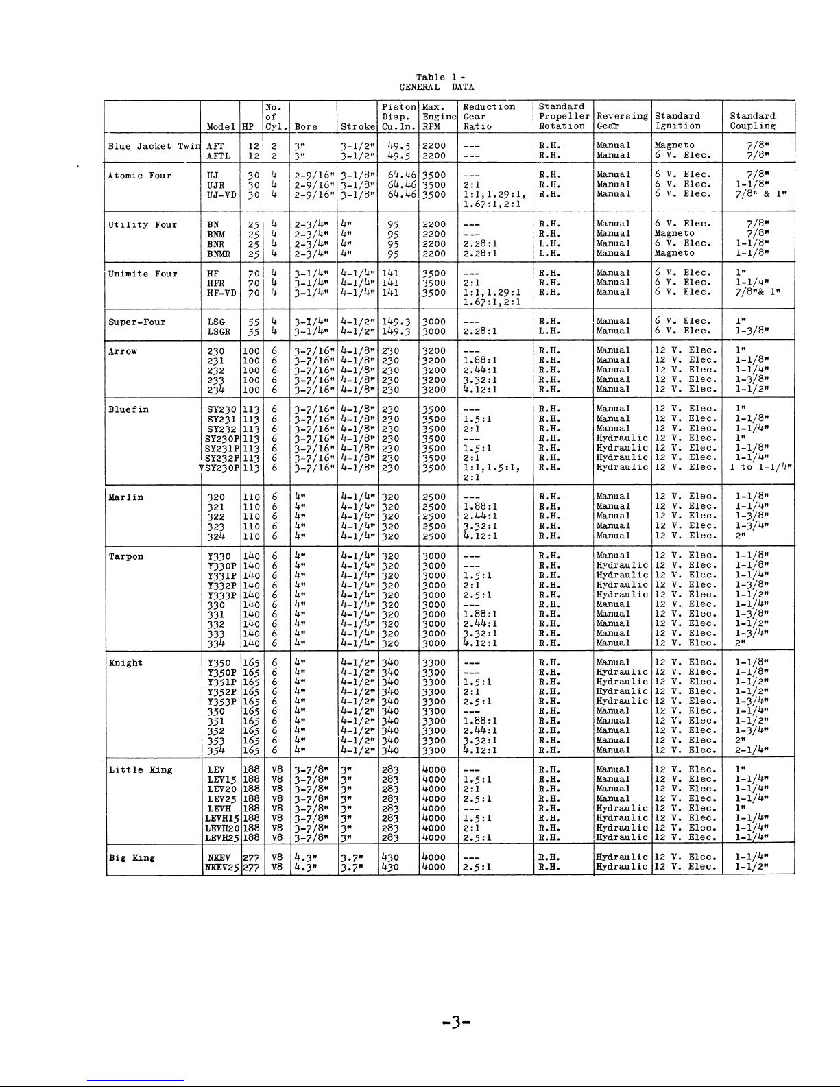
General
Installation
Electric
Lubrication
Fuel
Trouble
Valve
Torque
Bearing
Spark
Valve
Engine
Oil
Shooting
and
~Vrench
Data
Plug
Timing
Data
Data
System
Specifications
Piston
Data
Wire
Requirement
Procedures
Data
Tensions
Sizes
Data
3
16
17
35
36
60
65
65
65
58
65
vi
Page 12
SECT
ION
I
1.
INTRODUCTION
This
instructions
oper'ation
rent
and
title
the
the
differences
dels
tain
a.
radically
bile.
far
of
ceived
marine
model
clusively
provements
continually
is
100%
b.
service
in
advancements.
water
to
and
clean-out
metals;
verse
coolers;
of
c.
clusive
marine
come
you become
wi
signed
and
instruction
and
production
former
page.
book
models
to
will
Marine
This
back
the
Universal
engine.
after
tbe
Mar
To
provide
use,
jackets,
all
at
even
and
non-corroding
Universal
to
th
your
economical
NORSEMAll.
generally
listed.
which
be
engine
from
fact
as
and
for
and
world's
ine
that
Universal
cylinders
temperature;
plate;
built-in,
reduction
and
features
engines
appreciate
familiar
Universal.
to
assure
GENERAL
book
for
the
maintenance
models
models
Instructions
pertain
When
occur,
the
referred
1898 when
built
Through
model was
marine
refinements
added.
Engines.
for
mar
These
gear-type
engines
the
instructions
requirements
those
was
Motor Company
the
Today
largest
the
ine
engines
has
pioneered
with
in
equal
corros
not
construction.
not
--
features
more
and
long,
service
gives
installation,
of
model
to
of
recognized
the
first
tbe
designed,
service,
more
include
water
water
ion-res
attached,
gears;
water
have
found
Each one
afloat.
general
of
all
UNIVERSAL
listed
througbout
to
specific
or
directly.
differ
the
automo-
founders
100%
years,
bave
Universal
builder
severe
encounter
larger
supplied
quantities
jacket
istant
many
in
you
and
more
experienced
dependable
cur-
on
all
of
mo-
per-
as
con-
as
ex-
im-
been
of
many
re-
oil
pumps
ex-
other
will
as
is
de-
INFORMATION
d.
in
Yet
goes
be
purpose
"wby"
maintenance.
care
tisfaction.
2.
a.
run
to
for
pressure,
which
ting
All
and
is
b.
from
and
marine
c.
drawn
spark
resisting
and
corrosion
shipment
d.
crates
the
and
operation.
3.
Before
make a
engine
New
is
-1-
nuts
Every
building
metals
necessary.
FACTORY
Each
on
full
adjustments
are
shipped.
Run-in
the
the
Special
cylinder
Heavy
engine
TREATMENT
gaskets
wise
modern
on,
will
oil
will
satisfactorily
plug
ready
and
certain
of
this
and
assure
PREPARATION
Universal
its
own
throttle.
leaks,
and
assure
undisturbed
lubricating
oil
engine
paint.
into
openings,
coating
within
and
frame
insure
installing
complete
for
damaged
to
bolts
facility
these
will
It
"bow"
A
power from
pan,
rust
the
walls.
storage.
the
in
for
OF
tend
check
marine
wear,
adjustments
is,
book
of
reasonable
your
built
Each
water
all
otber
the
are
made
all
painted
preventive
engine
to
the
shipping
customer
excellent
installation
ENGINE
inspection
to
all
for
is
and
tberefore,
to
show you
operation
amount
complete
FOR
engine
idle
is
leaks,
conditions
engine
when
when
openings
valves,
or
tigbtness.
installed.
during
the
oil
is
with
through
gives
This
engine
skids
receiving
condition
ON
ARRIVAL
a new
loose
compress
accessible
employed
engines.
as
time
will
the
the
and
of
sa-
SHIP}lliNT
is
speed
checked
oil
opera-
test
engine
drained
sealed
special
oil,
the
a
rust
pistons
prevents
durin€
and
and
engine
of
the
parts.
so
it
The
Page 13
is
wise
nuts
and
various
the
engine
t
ion
which
4.
ENGINE
to
check
bolts
tags
and
contain
should
ROTATION
all
for
tightness.
decals
important
be
carefully
accessible
attached
informa-
noted.
The
to
use
left
rotation
all
of
series
left
5.
hand
ENGINE
hand
propellers.
engines
the
six
and
and
in
every
propeller.
IDENTIFICATION
are
available
eight
case
utilize
Opposite
in
cylinder
a
Engines
rotation
in
all
only
the
two
reduction
Utility
These
type
the
reduction
rotation
designated
use
a
types
exceptions,
Four
two
and
models
right
and
gear
gear
Super-Four
utilize
gears
and
they
as
standard
hand
ratios
and
models
which
propeller
with
these
of
series.
external
change
therefore
are
the
Each
engine
indicating
nation
serial
the
ial
and
number.
model
number
designation
identification
is,
therefore,
you
use
time
your
this
you
request
engine
bears
the
the
engine
individual
The
constitutes
of
very
identification
information
or
order
a name
model
desig-
engine's
combination
and
the
positive
the
engine.
essential
parts.
plate
of
ser-
It
that
every
about
-2-
Page 14
Blue
Jacket
Atomic Four
Ut
il
i
ty
Four
Unimite
Super-Four
Arrow
Bluefin
Marlin
Tarpon
Knight
Little
Big
Four
King
King
Twil
Model
AFT
AFTL
UJ
UJR
UJ-VD
--
BN
BNM
BNR
BNMR
HF
HFR
HF-VD
LSG
LSGR
230
231
232
233
234
SY230
SY231
SY232
SY230P
SY231P
SY232P
VSY230P
320
321
322
323
324
Y330
Y330P
Y331P
Y332P
Y333P
330
331
332
333
334
Y350
Y350P
Y351P
Y352P
Y353P
350
351
352
353
354
LEV
LEV15
LEV20
LEV25
LEVH
LEVH15
LEVH20
LEVH25
NXEV
NKEV25
No.
of
Cyl.
HP
12
2
12 2
4
30
4
30
4
30
_._
..
_.
------
4
25
4
25
4
25
4
25
4
70
4
70
1+
70
4
55
4
55
6
100
100 6
100 6
6
100
100 6
6
113
6
113
6
113
6
113
6
113
6
113
6
113
110
6
6
110
6
110
6
110
110 6
140 6
6
140
140 6
140 6
140 6
6
140
140
6
140 6
140
6
6
140
6
165
6
165
6
165
6
165
6
165
6
165
6
165
6
165
6
165
6
165
188
V8
188
v8
188
v8
188
va
188 v8
188 v8
188
v8
188 v8
v8
277
v8
277
Bore
3"
3"
2-9/16"
2-9/16"
2-9/16"
r-------
2-3/4"
2-3/4"
4
2-3/
2-3/4"
3-1/4"
3-1/4"
3-1/4"
4" 4-1/2"
3-1/
3-1/4
3-7/16"
3-7/16"
3-7/16"
3-7/16"
3-7/16"
3-7/16"
3-7/16"
3-7/16"
3-7/16"
3-7/16"
3-7/16"
3-7/16"
4"
4"
4"
4"
4"
4"
4"
4"
4"
4"
4"
4"
4"
4"
4"
4"
4"
4"
4"
4"
4"
4"
4"
4"
4"
3-7/8"
3-7/8"
3-7/8"
3-7/8"
3-7/8"
3-7/8"
8
3-7/
3-7i8"
4.3"
4.3"
"
11
"
Stroke
3-1/2"
3-1/2"
3-1/8"
3-1/8"
3-1/8"
4"
4"
4"
4"
4-1/4"
4-1/4"
4-1/4"
4-1/2"
4-1/8"
4-1/8"
4-1/8"
4-1/8"
4-1/8"
4-1/8"
4-1/8"
4-1/8"
4-1/8"
4-1/8"
4-1/8"
4-1/8"
4-1/4"
4-1/4"
4-1/4"
4-1/4"
4-1/4"
4-1/4"
4-1/4"
4-1/4"
4-1/4"
4-1/4"
4-1/4"
4-1/4"
4-1/4"
4-1/4"
4-1/4"
4-1/2"
4-1/2"
4-1/2"
4-1/2"
4-1/2"
4-1/2"
4-1/2"
4-1/2"
4-1/2"
4-1/2"
3"
3"
3"
3"
3"
3"
3"
3"
3.7"
3.7"
Table
GENERAL
Piston
Max.
Disp.
Engine Gear
RPM
Cu.
In.
2200
49.5
2200
49.5
6'+.46
3500
64.46
3500
64.46
3500
2200
95
2200
95
2200
95
2200
95
141
3500
141
3500
141
3500
149.3
3000
3000
149~3
3200
230
230 3200
3200
230
230 3200
3200
230
230
3500
230
3500
230 3500
230
3500
230 3500
230
3500
230 3500
320 2500
320 2500
2500
320
2500
320
2500
320
3000
320
3000
320
3000
320
3000
320
3000
320
3000
320
3000
320
3000
320
320 3000
3000
320
340
3300
340
3300
340
3300
340
3300
340
3300
340 3300
340
3300
340
3300
340
3300
340 3300
4000
283
4000
283
4000
283
4000
283
4000
283
4000
283
4000
283
4000
283
4000
430
4000
430
1DATA
Reduction
Ratie..
---
---
---
2:1
1 : 1 ,
1.
67:
---
---
2.28:1
2.28:1
---
2:1
1:1,1.29:1
1.67:1,2:1
---
2.28:1
---
1.88:1
2.44:1
3·32:1
4.12:
---
1.5:
2:1
---
1.5:1
2:1
1:1,1.5:1,
2:1
---
1.88:1
2.44:1
3.32:1
4.12:1
---
---
1.5:
2:1
2.5:
---
1.88:
2.44:1
3.32:1
4.12:
---
---
1.5:1
2:1
2.5:1
-.,..-
1.88:1
2.44:1
3.32:1
4.12:1
---
1.5:1
2:1
2.5:1
---
1.5:
2:1
2.5:
---
2.5:1
1.29
1,2:
1
1
1
1
1
1
1
1
: 1 ,
1
Standard
Propeller
Rotat
ion
R.H.
R.H.
R.H.
R.H.
il.H.
R.H.
R.H.
L.H.
L.H.
R.H.
R.H.
R.H.
R.H.
L.H.
R.H.
R.H.
R.H.
R.H.
R.H.
R.H.
R.H.
R.H.
R.H.
R.H.
R.H.
R.H.
R.H.
R.H.
R.H.
R.H.
R.H.
R.H.
R.H.
R.H.
R.H.
R.H.
R.H.
R.H.
R.H.
R.H.
R.H.
R.H.
R.H.
R.H.
R.H.
R.H.
R.H.
R.H.
R.H.
R.H.
R.H.
R.H.
R.H.
R.H.
R.H.
R.H.
R.H.
R.H.
R.H.
R.H.
R.H.
Reversing
Gea1:'
Manual Magneto
Manual
Manual 6
Manual 6
Manual 6
Manual 6
Manual
Manual 6
Manual
Manual 6
Manual 6
Manual
Manual 6
Manual
Manual
Manual
Manual 12
Manual
Manual 12
Manual
Manual
Manual
Hydraulic
Hydraulic
Hydraulic
Hydraulic
Manual
Manual
Manual
Manual 12
Manual
Manual
Hydraulic
Hydraulic
Hydraulic
Hydraulic
Manual
Manual 12
Manual
Manual
Manual 12
Manual
Hydraulic
Hydraulic
Hydraulic
Hydraulic
Manual 12
Manual
Manual 12
Manual
Manual
Manual
Manual 12
Manual 12
Manual
Hydraulic
Hydraulic
Hydraulic
Hydraulic
Hydraulic
Hydraulic
Standard
Ignition
6
V.
Elec.
Elec.
V.
V.
Elec.
V.
Elec.
V.
Elec.
Magneto
Elec.
V.
Magneto
V.
Elec.
V.
Elec.
6
V.
Elec.
Elec.
V.
6
V.
Elec.
12
V.
12
V.
V.
12
V.
V.
12
V.
12
V.
12
V.
12
V.
12
V.
12
V.
12
V.
12
V.
12
V.
12
V.
V.
12
V.
12
V.
12
V.
12
V.
12
V.
12
V.
V.
12
V.
12
V.
12
V.
V.
12
V.
12
V.
12
V.
12
V.
12
V.
V.
12
V.
V.
12
V.
12
V.
12
V.
V.
V.
12
V.
12
V.
12
V.
12
V.
12
V.
12
V.
12
V.
Elec.
Elee.
Elee.
Elee.
Elee.
Elee.
Elee.
Elec.
Elec.
Elec.
Elec.
Elee.
Elec.
Elee.
Elec.
Elec.
Elec.
Elee.
Elec.
Elee.
Elee.
Elec.
Elee.
Elec.
Elec.
Elee.
Elee.
Elec.
Elec.
Elce.
Elec.
Elec.
Elec.
Elee.
Elee.
Elec.
Elec.
Elee.
Elee.
Elee.
Elee.
Elee.
Elee.
Elee.
Elee.
Elee.
Elee.
Standard
Coupling
7/8"
7/8"
7/8"
1-1/8"
7/8"
& 1"
7/8"
7/8"
1-1/8"
1-1/8"
1"
11
1-1/4
7/8"& 1"
1"
1-3/8"
1"
1-1/8"
1-1/4"
1-3/8"
1-1/2"
1"
1-1/8"
1-114"
1"
1-1/8"
1-1/4"
1
to
1-1/4"
1-1/8"
1-1/4"
1-3/8"
1-3/4"
2"
1-1/8"
1-1/8"
1-1/4"
1-3/8"
1-1/2"
1-1/4"
1-3/8"
1-1/2"
1-3/4"
2"
1-1/8"
1-1/8"
1-1/2"
1-1/2"
1-3/4"
1-1/4"
1-1/2"
1-3/4"
2"
2-1/4"
1"
1-1/4"
1-1/4"
1-1/4"
1"
1-1/4"
1-1/4"
1-1/4"
1-1/4"
1-1/2"
-3-
Page 15

1.
PREPARING
Remember
of
installing
under
Provide
too,
amount
all
to
the
As
until
three
small
sion
should
abaft
the
will
the
tion
boats,extra
along
Tbe
determining
of
things
tbis
The
the
between
tom
Clearance
tbe
tban
of
and
that
to
blocking
support
people
the
first
tbe
feet
boats,
will
be
tbe
transom.
give
same
free
tbe
next
the
of
propeller
shaft
must
can
be
width
propeller,
the
the
4",
the
propeller
plenty
time
FOR
that
around
the
a
considerable
must
this
working
step,
bull
off
a
be
placed
bow
adequate
of
obstruction.
blocking
keel.
step
tbe
be
establisbed.(See
of
propeller
boat
between
and
INSTALLATION
as
much
an
engine
the
boat
of
room. Remember,
boat
tbe
three-point
sufficient.
and
Tbis
leave
in
tbe
sbould
room
and
be
weight
in
shore
is
floor.
about
at
type
support
tbe
location
hole.
considered
rudder,
and
(minimum
tbe
to
witbout
Fig.l
of
Underwater
SECT
INSTALLATION
of
the
work
takes
as
the
weight
strong
plus
the
up
approximately
each
of
tbe
stern
sbould
procedure
A number
the
and
2").
rudder
not
allow
Location
place
inside.
engine
enough
that
boat.
the
boat
For most
suspen-
Blocking
six
corner
On
and
clearance
first
feet
blocking
and
sec-
larger
be
used
angle
before
Fig.l)
size
tbe
bot-
be
less
removal
Gear
and
of
of
at
is
of
of
and
re-
ION
moving
tory.
sary
tbe
recommended
angles
are
bole
simple.
down
convenient
drawing
engine,rudder
proper
propeller
cardboard
marked.
diameter,
divided
example,
be
and
and
engine
accurate
balf
centerline
sbould
piece
given
With
similes
ance
tbe
til
lines
propeller,
wbere
keel
of
cbecked
cient
bottom
of
recommended
14
II
engine
If
full
available,
represented
4"
6"
the
accounted
engine
tbe
carefully
tbe
tbe
degrees
the
rudder
It
is,
of
to
know
of
and
It
a
full-sized
places.
Tbe
by
a 12 x 12
wide
wide
cutout
reproduction
of
the
be
of
paper
on
tbe
in
centerline
up
with
this
engine
to
clearan~e
of
tbe
engine
the
and
maximum
engine
scale
establishing
is
only
spot
full-size
and
need
with
length
and.
tbe
tbe
for
for
engine
clearly
drawn
engine
rudder
place
is
tbe
and
line
be
sure
boat
operating
in
is
more
course,
exact
tbe
drawings
locating
and
Tbe
only
tbe
number
by a piece
should
witb
using
and
for,
then
tbe
passes
noted.
is
between
does
most
manufacturer's
and
operation.
necessary
profile
place
cutouts
propeller
cutout
be
center
sbould
widtb,
of
propeller
a
three-blade
a
two-blade.
with
marked.
care
tbe
scale
and
propeller
proper
the
moved
of
centerline
spot
then
there
and
tbat
not
engines).
satisfac-
also
location
of
the
an
blades.
be
of
the
dimensions
..
tbe
and
througb
The
it
exceed
angle
neces-
mInImum
the
tbe
angle
to
in
over
of
in
for
oblong
carefully
equal
tbe
12"
a
fairly
the
on a
drawing.
clearcutout
about
of
position
carefully
is
suffi-
and
tbe
of
boat
sbaft
is
lay
some
this
the
their
the
of
tbe
pitcb
For
would
long
prop
Tbe
lower
sbaft
This
large
fac-
of
un-
shaft
tbe
angle
tbe
tbe
angle
tbe
(5
to
The
-4-
Page 16

~~~-
A
-----
justed
clearances
wheel
the
accurately
passes
fully
in
_ -
----:c--
-::
__
-::;.::----=---
matter
these
'\
I .
\
~prNOFNtIG'N&
6~~()W~r
bottom
the
hole.
2.
to
obtain
and
clearance
position
determined,
each
of
marked
the
boat.
to
lay
marks
of
the
(1,2,3
position
INSTALLING
crankcase
for
of
the
the
and
the
It
a
boat
and
THE
proper
propeller
and
the
engine.
string
the
sticks
jig
is
is
placed
then
straightedge
on
Fig.2)
which
angle
of
will
the
PROPELLER
has
place
care-
a
simple
along
to
shaft
SHAFT
fly-
When
been
it
back
the
give
Fig.2
engine
raising
the
:Method
must
or
angle.
fore-or-aft
determined
If
full
are
method
lay
the
spot
gine
ly
r i
it
is
To
this,and
nail
where
will
strip
the
stern
feet
Narrow
the
foot
angles
the
the
is
a
s
ide
and
A
string
board
to
the
of
the
scale
not
available,
of
a
length
center
well
10cation.(See
prop
roughly
another
the
be
located.
(C)
stern,
and
below
strips
top
strip,
along
to
sticks
boat.
full
of
the
laid
which
one
fl~1heel.
of
be
lowering
Do
not
from
location.
drawings
locating
of
of
the
beyond
this
str
parallel
at
a
strip
flywheel
so
that
follows
projects
the
are
its
length
it,
so
just
This
sized
boat,
flat
is
on
then
represents
represent
Locating
lined
move
its
Sbaft
up
it
or
the
previously
of
eitber
changing
the
another
this
1 x 4
transom
the
Fig.2).
ip
right
(B)
Fasten
it
the
at
bottom
nou
spot
lumber
forward
determined
Tempora-
(A)
in
place
to
the
angle
at
the
of
the
a
passes
angle
least
of
the
fastened
approximately
and
at
that
touch
jig,
pattern
can
the
stretched
the
the
which
of
now
be
floor.
bottom
actually
the
from
the
ing
The
the
string
locat
Hole
by
engine
boat
simple
is
to
from
to
en-
so
keel.
to
it,
point
engine
second
outside
of
the
three
boat.
to
every
right
ends
of
of
in-
removed
the
transom
ion
is
ad-
a
A wedge
will
fit
inboard
be
fashioned
mabogany
easy
lent
should
shaft
angle
of
of
to
marine
be
log
corresponding
the
the
shaft
thickness
with
the
should
thick.
wedge
keel
shaft
In
wedge
keel
may
since
log.
this
should
and
alongside
as
snugly
should
is
now
between
shaft
log.
from
is
recommended
Fig.
work
3
with
material.
as
wide
to
be
used
shaft
hole
log.
of
the
angle
be
approximately
In
some
cases,
exceed
it
must
event,
the
be
tbeedges
the
keel
as
possible.
also
be
notched
constructed
the
keel
This
any
hardwood,
since
Shaft
and
Log
is
This
and
as
long
and
with
minus
(See
wedge
but
Fig.3)
will
the
the
the
width
be
as
wide
underside
shaped
to
shaped
and
fit
The wedge
out
which
and
wedge
an
excel-
wedge
as
cut
at
the
angle
the
angle
thin
1/2
width
of
as
of
fit
to
the
to
the
may
but
it
the
The
vary
edge
inch
the
the
the
the
fit
hull
fit
is
an
of
-5-
Page 17

any
ribs
wedge
over
Use a
between
fasten
scre'ws,
scre'~Ts
with
Fig.4
After
pare
hole.
is
the
good
the
securely
being
'where
the
Method
the
for
Preparation
consists
hardwood
guides
in
started
angle
These
of
blocks
grained
wi
11
do.
They
2"
thick,
which
then
locat
might
screwed
ion
grade
wedge
careful
they
shaft
log
of
wedge
the
of
drilling
the
blocks
getting
properly
drilling
should
hardwood
should
5"
wide
interfere.
into
of
the
shaft
bedding
and
the
to
the
to
place
will
not
mounting
--:::::-
- - - - I<£EL
Drilling
is
in
Shaft
place,
of
for
this
construction
which
and
the
will
shaft
keeping
fairly
be
of
maple
be
approximately
and
10"
The
position
hole.
compound
keel
keel
and
with
these
interfere
screws.
Hole
pre-
the
shaft
step
of
two
act
hole
the
accurate.
straight-
or
oak
long.
as
A
drill
shaft
provide
of
drill
drill
long
enough
blocks
penter's
since
the
grain
a
wandering
be
found
shank,it
on a
stee
passed
and
the
moved
blocks
Now
lay
and
over
cases,
out
the
tom
of
notch
to
allow
a
gasket
gasket
the
shaft
1/8
diameter
PI' opel'
may
a
clean
to
and
the
auger
the
"wore"
end
hole.
with
can
be
1
I'
ad.
completely
bottom
and
the
unscrewed
the
shaft
the
it
will
wedge
the
shaft
slight
for
ly
later
from
mat
er
ial
log
inch
larger
should
be
c-learance.
be
used
hole
pass
which
and
has
through
keel. A standard
is
not
recommended
tends
using
a
it
may
If
a
drill
sufficiently
extended
~;ll.en
the
through
block,
two
temporary
from
shaft
be
necessary
to
conform
log
it
the
on
hole.
log.
larger
than
alignment.Fashion
1/16"
and
and
wedge.
rubber
place
than
used
Any
a
shank
the
to
follow
result
cannot
by
welding
dr
i 11
the
can
be
drilling
boat.
the
wedge
In
to
chisel
to
the
Make
necessary
or
1/32"
it
between
the
to
type
will
two
car-
in
long
has
keel
re-
some
bot-
this
One
and
of
the
with
hole
the
proximate
emerge.
tened
cut
the
keep
a
to
notch
shank
drill
Fig
of
5)
the
block
and
bottom
so
drilling
the
guide
6"
~
5)
is
boat
the
to
as
from
cut
of
at
these
fastened
lines
position
th9
of
position
The
the
to
drilling
block
this
in
the
the
blocks
so
other
the
face
inside
be
angle.
can
this
drill
to
that
up
is
boat
of
at
right
angle
be
starting
block
will
proper
(See
the
the
approximately
of
the
fastened
at
the
hole
the
block
of
the
In
fastened
to
support
angle.
Fig.
inside
center
shaft
the
ap-
will
fas-
boat
angles
order
accurate,
block.
fit
the
the
(See
4
of
to
is
to
to
3"
A
Fig.5
Insert
shaft
over
log
approximately
halo
sides
a
good
shaft
enough
and
Next
-6-
hole
the
so
in
of
log
well
slip
Photo
the
hole,
that
the
the
marine
in
to
pass
into
the
of
Drilling
propeller
and
uith
position
the
propeller
in
the
shaft
shaft
sealer
place
through
the
keel.
shaft
the
log.
log
and
with
strut
Operation
shaft
shaft
the
center
Coat
gasket
fasten
screws
the
in
shaft
shaft
of
'wedge
over
the
log
is
the
both
with
the
long
the
Page 18

shaft
peller
firmly
shaft
of
the
to
the
tighten
wedges,
in
the
justment
its
hold-down
justing
and
shaft
move
with
against
is
approximately
bear
keel
ing
at
down.
center
shaft
of
the
nuts
securely.
it
the
hole.
this
Using
the
hole.
strut
screws
along
the
base
keel
in
Screw
point
small
propeller
Make
and
and
the
until
the
the
but
final
angle
pro-
pressed
the
center
strut
do
not
wooden
shaft
ad-
tighten
ad-
gine
on
the
at
8-"
members
to
--
beds.
hull
intervals
them.
_ _
They
ribs
by
.Lunning
:~d
braces
N[ fll,4fr
ENG!
IN-LINE PANGERS
should
and
be
notching
at
CENT[R
-
rest
firmly
cross-braced
into
right
and
-l-;;;FT
angles
stringers
TO
JlANGER
lJUrANCe
2"
by
3.
INSTALLING ENGINE STRINGERS
BEDS
Engine
stalled
tudinal
two-thirds
and
fastened.
these
the
placed
mount
Fig.6
are
constructed
maple
som
of
tance
distance
of
of
to
hull
ing
not
to
the
the
the
stringers
(See
members
the
them
In
members
plans
to
take
centers.
Photo
in
and
should
at
least
engine
between
between
engine
material
Fig.6).
the
most
will
and
an
of
place,
of
8"
them
plus
should
should
length
engine
modern
be
usually
engine
If
these
Engine
they
by
run
from
three
location.
should
mounting
one
to
be
These
now
run
at
of
the
bed
included
with
str
Stringers
should
2"
oak
the
feet
The
be
thickness
used
AND
be
in-
longi-
least
hull,
will
hulls,
will
22~"
ingers
tran-
forward
dis-
the
centers
for
en-
be
in
be
be
or
_-t
)}/I/FT
TO
IIANGER \
PlfTANC£
Fig.7
should
These
to
that
be
underside
The
of
These
to
the
rial
at
the
shaft
hanger
gers
or
these
mined
shaft
through
stuffing
piece
in
engine
A
piece
then
string
engine
a
simple
cross-braces
the
will
cut
next
the
are
10"
engine.
needed
which
depth
line,
are
offset
engine
of
place
placed
_ EtJu1tJE JHAf
~
_-
- -
OFF5ET
Engine
be
drift-bolted
shape
be
to
fit
of
step
engine
pieces
longer
will
the
engine
of
-
that
parallel
in
by
removing
and
the
box
stock
somewhat
location.
of
engine
in
the
is
to
matter
r CEtJ
_ - -
~f~;'i~
---:--
,--
- -- - -
NANGI:RJ
Bed
of
the
under
the
the
engine.
is
the
bed.
of
than
The
width
depend
the
and
engine
the
is,
to
height.
beds
stretching
strut,
and
fastening
tacked
bed
on
edge
position
be
mounted.
to
TER
- -1 JJlAFTTOIIAIVGEk
8£0
--
..J.--
tJl/TAIVCE
--
----.
vonstruction
together.
should
hull
the
contour
conform
and
engine
of
construction
is
(See
2"
the
to
Fig.
hardwood
length
of
the
on
the
be
mounted,
below
type
whether
the
is
the
shaft
shaft
The
easily
of
engine
the
height
deterpropeller
a
string
hole
it
temporarily
forward
of
material
alongside
~here
It
is
measure
those
must
the
7).
8
of
mate-
angle
the
han-
line
of
and
to
the
is
the
the
then
down
n
a
-7-
Page 19

from
the
the
center
position
figures
given
drawing.
parallel
shaft,
are
gle
then
as
the
the
distance
the
forward
are
offset,
bed
the
the
of
After
is
shaft
is
string
str
ing
the
the
completed,
cut
ing
distance
engine
the
and
coupling
engine
boat
place
in
ling
as
must
and
with
close
half
possible.
one,
a
on
each
the
is
an
can
pole
the
engine
large
"A
be
this
securely
engine
end
I!
frame
used.
by a trucl{
In
any
case,
taken
cure
that
and
strength
rope
could
and
With
place,
place
inside
place,
~4C"
then
length
the
inch
serted
or
slipped
result
a
very
the
slide
under
of
fasten
clamps.
bored
of
stringers
carriage
in
string,
of
of
the
If
the
to
the
top
simply
string
of
the
and
the
in
steps
with
to
the
to
pattern
replace
fasten
in
place
now
temporarily
the
alignment
on
the
If
the
can
be
of
the
in
place.
or
help
wi
Or
equipped
extreme
all
hitches
all
to
tackle
hold
in
discouraged
engine
the
the
stringers.
them
Four
equally
the
engine
the
holes
which
the
shaft,
hangers
on
the
engine
mounting
centerline
of
the
cut
at
and
mounting
rear
top
mounting
of
at
the
top
from
the
of
mounting
of
the
distance
the
the
the
on
the
be
lifted
propeller
propeller
engine
done
to
the
and
with
pole
bodily
If
is
not
th a block
the
job
with
care
of
the
load.
knot
a
at
very
securely
the
engine
engine
temporarily
1/2"
spaced
bed,
and
bed.
bolts
are
and
represents
to
using
lugs
engine
the
same
below
lugs.
the
the
angle
each
centerline
engine
propeller
propeller
shaft.
into
blocked
coupling
to
the
shaft
is
a
by
fastening
lifting
two
lifting
the
available,
and
can
be
a
must
used
are
sufficient
A
this
leaky
boatman.
blocked
beds
and
i~'hen
holes
along
through
One-half
then
securely
the
the
scale
are
of
the
beds
an-
it
the
lugs
engine
of
from
equal-
lugs.
bed
The
the
in
coup-
as
small
eye
men
on
engine
tackle
done
winch.
be
se-
broken
point
boat
in
in
on
the
in
with
are
the
in-
If
tightened.
nuts.
The
hold-down
the
top
In
some
to
drill
turbing
engine
holes
than
must
us
the
fastening
Use
position
bolts
surface
cases,
these
the
engine;
be
ing a dr
lag
the
Three-eighths-inch
will
engine
Insert
with
screw
turns
4.
The
the
with
gine
faces
propeller
within
feeler
around
ded
the
no
narrow
between
around
alignment
looseness
Each
tighten
check
time
ture
Do
faces
springing
the
bolt
together
around
the
shaft
check
box
location
project
beds
the
washers
them
of
being
ALIGNING
blocking
engine
the
propeller
will
under
two
feeler
time a shim
will
performance.
not
engine
the
engine
or
be
of
the
.003
gauge
the
the
faces
gauge
str
ips
the
the
of
all
alignment.
attempt
of
the
the
two
and
the
in
should
for
tightness
slight
or
engine
to
THE
and
coupling
of
two
two
circle.
can
hold-down
payoff
is
propeller
angle.
washers
of
is
now
of
the
it
will
holes
removed.
ill
1/8
screws
to
engine
lag
three
will
inches
be
hold-down
under
the
within
tight.
ENGINE
can
now
be
the
engine
shaft.
in
alignment
two
is
faces
engine
are
of
faces
then
anyone
coupling
propeller
in
halves
remove
neutral,
turn
misalignment
halves
an
inch
us~d,
in
is
available,
paper
at
Any
be
of
is
added
Extra
in
to
bring
perfect
of
the
easily.
in
under
the
marked
engine
be
possible
without
in
others,
Drill
inch
be
used
in
screws
into
sufficient.
heads
three
removed.
lined
when
are
or
parallel
less.
checking
and
shims
hangers
alignment.
can
be
four
variation
felt
the
or
removed,
bolts
care
terms
the
together
shaft.
alignment,
the
coupling
wedges
shaft.
the
propeller
the
stuffing
in
all
engine
beds.
dis-
the
these
smaller
for
place.
which
the
bolts
and
or
four
from
The
enthe
of
the
all
ad-
until
four
placed
points
by
the
strips.
and
re-
at
this
of
fu-
two
,~rhen
from
~ith
If
not,
strut
on
up
A
If
of
by
-8-
Page 20

ENGINE
ENlJ
With
engine
aligned,
with
power,
haust.
be
extent
used,
cation
fuel,
and
now
installed
on
location
of
personal
stern
things
exhaust.
should
workmanlike
practices
5.
EXHAUST
Exhaust
a~
large
haust
or
galv2nized
piping
as
mp.nifold.
installed
it
must
'1ater,
provisions
these
will
the
model
of
the
instrument
preference
In
be
manner
adhered
PIPIKG
should
the
opening
Either
pipe
and
now
be
and
made
elements
depend
of
engine
the
gas
as
any
case
installed
and
certain
to.
be
copper
may
properly
supplied
electrical
for
are
to
tank,
panel
to
side
these
at
least
on
the
be
used.
ex-
to
some
being
lo-
and
or
in
a
good
ex-
tubing
If
to
direct
engine
so
the
low
quiets
into
doing,
hot
the
the
exhaust
daI.lg~r
installation,
be
oTJserved.
enter
belm'!
opening
made
away
visions
cooling
Fig.
the
warping
There
cooled
't7ill
pose~
labor
the
the
and
to
direct
from
are
water
9
Hethod
exhaust
the
are
elbows
serve
~nd
of
fabricating
Hm1ever, a
by
welding
exhaust
exhaust
the
uater
the
~anifold.
line
oanifold
'7i
cooling_
the
two
purposes
point
,,-,.:haust.
two
First,
exhaust
bottoD
some
the
manifold.
necessary
from
manifold
hot
exhaust
several
on
both
are
worth
subst i tute
a
steel
at
least
11
be
(See
uater
exhaust
are
line
is
and
In
this
precautions
the
no
less
of
the
provision
the
flm'!
to
backing
of
Cooling
Discharge
and
valves.
types
the
market
of
the
their
a
substitute.
can
elbow
4" bel0'\7
in
such
directed
Fig.
from
line.
served:
cooled
the
~7ater
type
'"Jater
than
manifold
oust
of
't"later
Tbese
prevent
up
\~'ater
perhaps
of
water·
'7hicb
above
cost
be
into
a
T,;rf:'.Y
avray
9)
the
In
be-
of
must
must
5"
be
pro-
into
pur-
in
made
the
the
that
from
Fig.
elbows
they
A
short
Fig.
close
the
exhaust
the
8
are
should
piece
8)
placed
to
the
exhaust
line
engine.
Photo
of
nece'ssary
never
of
in
engine
and
prevent
due
It
is
Exhaust
exceed
steam
the
will
to
common
Piping
in
the
45
degrees.
hose
exhaust
help
fracture
vibration
practice
1
ine,
(See
line
quiet
of
of
6.
COOLIh'G
1~Tater
piping
standard
short
be
and
scoop
the
piece
used
the
should
water
installation
are
equipped
-9-
r,'ATER
copper
of
between
engine.
be
intake
permits.
with
SYSTEM
can
best
tubing.
flexible
the
The
located
on
reversing
be
hose
intake
water
as
the
Some
done
Again,
should
piping
intake
close
engine
engines
and
with
a
to
as
re-
Page 21

Fig.IO
Suggested
Battery
Installation
Installation
a
simple
3/4"
inside
witb
bedding
drilled
the
di~cnsion
The
tbe
bull
ing
pipe
thick
of
four
compound.
tbrougb
same
diameter
scoop
h~le
and
fastened
compound
on
the
tightened.
of
process.
block"
tbe
wood
of
tbe
pipe
from
is
tbe
is
inside
the
A 3"
is
fastened
bottom
screws
A
the
as
water
then
bottom
in
placed
and
water
of
and
bole
block
the
scoop
inserted
place.
tbe
scoop
square
to
tbe
set
is
and
outside
pipe.
of
A
around
locknut
is
by
tbe
bull
in
then
bull
in
tbe
seal-
the
duct
ion
cooled,
turer
water
piped
gears
in
wbicb
recommends
enter
from
at
tbere
tbat
tbis
to
are
case
tbat
tbe
also
tbe
tbe
point
engine.
water
manufac-
cooling
and
be
7.
THER£.fOSTAT
Host
witb
water
sea,
gine
often
water
to
circulates
and
board.
gine
the
temperature
temperature
water,
piping
tbe
discbarges
In
tbis
pump
AND
engines
pump
it
type
of
capacity
WATER
BY-PASS
are
that
simply
directly
through
it
of
system,
is
determined
the
and
OUTLET
TO
SUCTION
OF
WATER
VALVE
installed
from
the
all
incoming
the
degree
TO
SIDE
PUMP
dravls
the
en-
over-
en-
by
Fig.
11
Methods
BY-PASS
LINE
-{
HULL~'
of
Engine
-10-
Temperature
RETURN
BELOW
Control
+
CONNECTION
WATERLINE
~
BE
Page 22

of
restriction
the
piping.
find
as
t
system
ating
valve
the
case
sation
life.
tion
through
as
Fig.
engine
low
ions.
crankcase,
oil
temperature
shown
11.
as
We
because
temperature
sticking,
with
and
We
recommend a
the
in
temperature
of
water
overboard.
In
the
by-pass
warm
diverted
line
engine.
warm
engine
Control
by-pass
either
water
back
to
be
By
water
temperature.
of
line
a
thermostat
the
piping
valve
of
and
If
wiil
warm
raise
a
thermostat
water
its
automatically
the
warm
back
when
gine
to
the
the
temperature
thermostat
the
and
amount
will
maintain
about
1500 F.
to
It
is
operating
900 F.
do
not
in
recommend
the
sludge
dilution
cylinder
shortened
of
use
Do
by
of a by-pass
the
piping
not
attempt
restricting
either
syetem
leaving
into
recirculated
varying
fed
back
water
hand
passing
is
accomplished
control
installed
diagrams.
divert
back
operat
divert
water
pump
engine
will
leaving
of
recirculated
for
is
react
divert
engine
flow
quite
temperatures
these
usually
is
conducive
formation
wall
valve
nominal
1500F.
diagrams
into
the
a
quantity
the
the
pump
through
the
to
the
can
be
through
valve
as
Opening
a
larger
into
ing
temperature.
is
used
nearly
recirculation
cold.
nears
1500 F.
to
only
enough
temperature
offered
common
installa-
this
low
of
type
oper-
crank-
conden-
spring
opera-
obtained
system
to
control
the
flow
pump
engine
is
suction
the
amount
pump
the
controlled.
the
with
or
shown
the
amount
the
engine
it
will
all
the
engine
When
enthe
decrease
water
to
by
to
to
in
of
or
of
of
a
in
of
at
the
valve.
On
installations
control
issuing
after
of
water
primed
stopped
is
found.
On
installations
only
times
the
operat
the
charge
valve,
from
the
indicates
and
until
a
trickle
only
exhaust
ing
thermostat
more
thermostat
small
and
til
quantity
keep
the
the
engine
temperature.
engine
on
the
steadies
8.
FUEL
A
marine
be
used
structed
always
temperature
to
SYSTE1f
type
in
with
and a filler
to
the
bottom
fire
such
in
this
the
occur
a
tank
filling
can
be
something
The
gasoline
also
and
just
tom.
larger
by
enters
passes
a
This
the
short
in
fuel
water
the
engine
the
the
exhaust
is
engine
source
using a thermostat,
of
water
steam
unt
il
the
temperature
will
water
is
designed
of
water
exhaust
reaches
\~ben
keep
a
constant
gasoline
all
installations,
internal
pipe
of
which
the
during
only
that
tube
snuffed
over
the
outlet
at
the
down
through
distance
pipe
size
should
than
pump on
using
should
started.
the
pump
of
and
will
issue
engine
at
,."hich
open
overboard.
to
to
pipe
start
a
ing
close
gauge
value.
tank
baffle
goes
tank.
the
filling
vapor
will
out
by
neck
of
from
top
of
the
off
be
that
the
engine.
the
pipe
be
has
hand
noted
soon
A
lack
not
should
trouble
some-
from
reaches
time
to
dis-
The
allow
pass
cool
un-
operating
a
cold
watch
until
should
con-
plates
nearl~'
Should
trapped
burn
anc
placing
the
tube.
the
tank
the
tank
tank
the
bot-
slightly
required
be
a
it
it
a
of
to
Generally,
faster
ture
control
range
valve.
be
adjusted
perature
of
the
cessary
the
warm
than
The
hand
at
engine.
to
continually
thermostat
up
and
over
will
control
to
give
the
usual
It
closer
the
the
should
will
tempera-
engine
hand
control
valve
adequate
running
not
re-adjust
give
speed
should
tem-
speed
be
ne-
The
overflow
the
tube
as
able
in
line
and
-11-
tank
will
tube
tank
of
size.
directly
through-hull
most
of
cases
the
tank
also
coming
at
least
This
as
possible
just
hull.
vapors
have
off
half-inch
tube
should
fitting,
below
Overflow
will
a
vent
the
top
copper
be
to
a
suit-
located
the
sheer
gasoline
thereby
and
of
run
be
Page 23

discharged
Connection
engine
tubing
engine
of
in
the
ment
leaks
the
9.
ELECTRICAL
should
of a size
manufacturer.
flexible
line
to
occurring
metal
harmlessly
from
be
line
at
the
the
fuel
tubing.
SYSTEM
over
the
made
tank
with
the
to
recommended
A
short
should
point
pump
due
to
be
of
to
fatigue
side.
the
copper
by
the
sect
ion
placed
attachprevent
of
with
most
types
controls
remote
through
lically
With
the
peller
shaft,
proper
of
the
engines
of
controls
may
lever,
a
system
through
engine
is
then
care
being
clearances
boat
and
or
available.
be
operated
either
of
rods
piping.
installed,
fastened
taken
from
the
rudder.
one
of
several
from a
mechanically
or
hydrau-
the
to
to
maintain
the
bottom
These
pro-
the
The
wir
importance
ing
aboard a boat
emphasized.
clean,
'There
sary,
tight,
solder
the
mechanically
Use
only
to
prevent
should
to
be
kept
mInImIze
circuits.
A
battery
close
securely
to
fastened
of a size
the
battery.
should
be
periodic
in
the
battery
All
wiring
a
fashion
injury.
should
be
minimize
cuit
rying
ing.
10.
The
stalled
at
sure
should
~ith
with
Gear
by
and
of
capacity
(See
FINISHING
instrument
at
the
control
and
be
the
the
unit.
shifting
using
the
of
adequate
All
connections
and
connections
connection
secure
rosin
flux
corrosion.
as
short
voltage
box
should
the
to
engine
prevent
Any
cover
readily
checking
(See
should
as
to
prevent
Wires
of
a
for
large
voltage
sufficient
to
prevent
Table
J)
THE
JOB
panel
any
convenient
station.
water
temperature
connected
instructions
can
be
shifting
cannot
free
should
before
when
All
as
drop
be
as
to
the
shifting
removable
of
water
Fig.
be
run
all
enough
drop
in
current
may
in
accomplished
lever
and
safe
be
over-
must
from
are
be
be
oil.
neces-
made
soldering
soldering
wiring
possible
in
the
built
as
possible,
boat
and
of
on
the
box
for
level
10).
in
such
mechanical
circuits
size
the
to
circar-
overheat-
be
in-
location
Oil
pres-
gauges
accordance
that
come
supplied
After
all
gine
gine
keep
it
ments
box
is
It
an
the
connections
should
box.
in
may
be
or
with
desirable.
must
internal
roughly
of
gasoline
fore,
be
at
with
sufficient
provided
full
the
higher
must
square
is
H.P.
gines
After
and
be
inches
sufficient
and
up
complet
with
alignment
propeller
once
more.
started
for
and
be
proper
that
the
run
and
and
signs
water
closely
operation.
everything
boat
at
slow
adjusting
the
tion.
engine
be
enclosed
In
designing
mind
the
necessary
repairs
removable
also
be
combustion
14
parts
when
to
allow
efficiency.
size
the
the
of
horsepower
ventilating
of
for
15
square
to
150
H.P.
ion
the
boat
of
the
shaft
The
engine
and
all
connections
of
leaks.
temperature
watched
should
be
speed.
is
boat
is
now
is
installed
completed,
possibility
to
make
in
the
top
kept
of
in
air
operating.
ventilation
it
This
the
engine;
the
ventilating
engines
inches
of
the
in
installat
the
engine
should
may
Oil
gauges
for
signs
After
is
operating
taken
Final
done
on
ready
the
in
an
this
adjustfuture.
and
mind
engine
to
one
There-
to
operate
will
greater
area.
up
for'
water,
to
be
checked
then
checked
pressure
should
of
making
properl
on a
checking
this
for
opera-
and
en-
enbox,
that
sides
that
uses
part
must
vary
the
Five
area
to
25
en-
ion
the
the
be
im-
sure
short
trip
A
-12-
Page 24

11.
V-DRIVE
In
recent
had a great
outboard
is
the
demand
the
other
with
water
mand
has
sufficient
skiers.
for
been
horsepower
ling
has
board
\ \
-
\\\\~--~C~R~A~NK~S~H~~~~~I
\ \
\ \
\ \
INSIDE
EDGE
Dr
TRANSOM
twin
been
engine
\\'\~I--------~~----~--~~~~~~~~--~
'II,
INSTALLATION
years
influence
type
hulls.
for
a
requirement
power
In
many
additional
met
by
the
outboard
motors.
the
installation
~ith
AFT
LINE
7"
ENGINE
SHAFT
KEEL
two
factors
on
One
greater
for
for
cases
power
use
of a higher
or
by
A
second
V-drive.
FROM
HORIZ,
ANGLE
24"
have
power
of
speed
for
these
and
engines
towing
the
de-
and
speed
instal-
solution
of
an
in-
-y-------
KEEL
In
this
leveled
six
mining
case,
from
feet
the
angle.
Location
termining
steps.
before
the
Any
will
keel
distances
termination
means
is
the
of
easiest
-Lc
® f
the
the
forward
shaft
of
tbe
its
angle
of
tbe
work.
bas
been
involved
of
a
simple,
I I
r--=13f~
keel
transom
to
bole
sbaft
methods
leveled
are
the
shaft
full-size
(See
should
aid
in
location
hole
are
tbe
described
However,
short,
Fig.
.+
3°
J~
WEDGE
MATERIAL -MAHOGANY
DIMENSIONS
to
about
deter-
and
since
and
angle
sketch
12).
be
and
de-
next
the
de-
by
In
Fig.
These
to
of
most
and
V-drive
be
mounted
tbe
outboard
are
12
boat.
being
houseboat
Tbe
installation
differs
from
conventional
the
the
wheel
Tbe
drive
The
tices
engines
engine
reverse
toward
installation
engine
general
will
altbougb
dimensions
Preparation
drive
engine
mounting
tbe
each
step
same
case.
is
the
Typical
Sbaft
engines
in
tbe
Tbey
are
bulls
used
hulls
successfully
up
to
of a V-drive
the
drive
is
installation
engine
mounted
position,
the
stern
of
will
be
described
principles
serve
for
tbe
may
vary.
for
mounting
is
like
conventional
steps
As
blocking
are
before,
up
Location
are
designed
extreme
suitable
17'
and
32'
in
in
aft
witb
a
of
tbe
typical
tbe
and
most
angles
that
engines
followed
the
of
the
stern
for
over
in
lengtb.
engine
of
that
and
in
fly-
boat.
Vberea
prac-
V-drive
and
the
V-
for
and
in
first
boat.
a
KEEL
Fig.
making
lines
feet
tween
of
the
tbe
on
sbaft
keel
mounting
prop
ing
angle
to
the
angle
turer's
tual
in
Fig.
this
are
long,
tbem
keel.
sketch,
center,
equal
angle
sbaft
down
to
and
the
engine
is
obtained
scale
measurement
12).
drawn from
intersects
THICKNESS
1'/2"
15/
"
s
,'/
.....
, 7/8"
2"
13
sketch,
dralm
with
the
equalling
A
line
indicat
at
to
the
(7
line
is
through
crankshaft
sbaft
d.rawings
A
third
the
point
the
top
F
''Ia''
-
1'/."
1'/8"
, "
'le"
Wedge
"//6
91,&
7/"
5/
'11,"
Sizes
two
H
"
"
"
....
parallel
approximately
distance
the
thickness
is
then
ing
the
an
angle
recommended
0
in
Fig.
now
the
12).
drawn
keel
line
angle.
from
of·the
tbe
of
the
or
engine
line
shaft
the
manufacfrom
is
keel,
six
be-
drawn
crank-
to
the
engine
The
slant-
at
an
equal
This
ac-
(24
tben
line
at
0
-:!.J-
Page 25

STERN
KEEL
OF
BOAT
BLOCK
"A"
an
angle
tbe
angle
used
this
(14
line
0
determines
0
(3
in
Fig.
The
location
now
from
by
ing
rudder
meter
the
after
wbicb
prop
be
tbe
the
dimensions
used,
and
and
bottom
end
will
sbaft
MATERIAL -MAPLE
to
the
shaft
of
tbe
in
Fig.
makes
tbe
with
angle
12).
of
the
determined.
transom
will
of
clearance
propeller,
propeller
of
the
boat.
of
the
be
at
that
where
the
OR
OAK
,.---
__
---,-L
I "ND
1--,0,,---1
DETAIL
line
sbaft
12).
tbe
of
shaft
Its
be
the
prope
clearance
propeller
T
I-
OF
BLOCK
Fig.
14
equal
log
The
keel
wedge
bole
distance
controlled
rudder
between
ller
Locate
pointrigbt
5·:..j
"B"
Drill
to
angle
tben
needed
can
betbe
dia-
the
hub
on
the
angle
to
be
to
BLOCK
MATERIAL
MAPLE
,
"8"
OR OAK
-=
\\4
~
-
===Lt
~'Z"--l
DETAIL
Block
distance
to
tbe
to
balf
inches.
balf
ward
from
line.
rigbt
now
transom.
to
tbe
passes
tbe
A wedge
tween
previously
OF
Details
from
bottom
tbe
Mark a
tbe
tbe
stern
tbe
after
Draw a
angles
represents
Meas"uing
spot
tbrough
location
can
tbe
~.
-j
I L
I
t&
zZI
[±]
f-5~
BLOCK
widtb
"A"
tbe
of
prop
spot
along
end
line
to
tbe
the
where
tbe
of
tbe
now
be
shaft
described.
prop
the
keel
diameter
four
of
the
the
of
from
tbis
keel.
inside
from
tbe
keel
shaft
cut
log
Fig.
sbaft
incbes
rudder
sbaft
tbe
This
tbis
shaft
will
hole.
to
and
center
is
equal
plus
prop
point
of
point
fit
keel
13
gives
two
plus
to-
line
hub
at
line
tbe
line
give
be-
as
Fig.
15
Typical
Bed,
Stringer
-14-
and
Steering
Set-up
Page 26

dimensions
for
varying
Afte~
installation
preparations
ling
the
dimensions
blocks
for
of
typical
keel
can
shaft
and
hole.
angles
installation
thickness.
of
the
be
made
Fig.14
for
)0
wedges
wedge,
for
dril-
gives
drilling
requiring
two-thirds
are
now
curely
rudder
installed
stringers.
is
shoun
The
gas
the
installed
to
the
A
typical
in
Fig.
tank
comes
length
and
transom,
and
15.
next.
of
the
fastened
and
braced
to
installation
In
hull
sethe
the
most
Fig.16
_______
a
Typical
V-Drive
Layout
___________________________
MAINTAIN
TO
REPACK
STllfflNG
THIS
DIMENSION
SHAFT
BOX
49.~¥-
~.~-
\1-
LOG
TOPVlfW
BfLLCRAIIIK
_
a
shaft
blocks
which
angle
are
will
of
available
greatly
17
step.
Following
the
strut
shaft
and
previous
log,
coupling
propeller
stalled.
Engine
stringers
running
0
Pre-drilled
•
in
most
simplify
instructions,
may
now
at
cases,
this
shaft,
be
in-
least
Fig.
V-drive
installed
transom
same
conventional
equally
From
the
engines.
structed,
-15-
17
safety
this
same
Photo
of
Installation
installations,
between
as
shown
features
installation
well
in
this
pOint,
as
for
conventional
The
engine
engine
Typical
the
the
engine
in
Fig.
described
case.
installation
beds
blocked
V-Drive
tank
and
16.
The
for
apply
drive
are
in
con-
place
is
is
Page 27

temporarily,
under
marking
engine
tened
stalled
the
is
in
of
place
and
alignment.
The
scoop,
strument
can
cribed
installation
fuel
panel,
now
be
for
Shifting
ventional
reverse
with
mote
pipe
that
in
the
gear
any
commercially
shifting
or
rod
the
V-dr
reverse
of a direct
the
remote
verse
of
the
forward,
beds
engine
the
mounting
then
removed,
and
brought
of
lines,
battery
accomplished
conventional
is
controlled
manner
by
lever
lever
stock.
ive
engine
position,
connection
lever
will
normal.
it
is
nec~ssary
slid
and
into
clamped
bolts.
beds
the
engine
into
water
oil
lines,
and
engines.
in
connecting
on
the
available
by
means
Due
to
is
the
will
operate
That
place
for
The
fas-
in-
proper
intake
in-
exhaust
as
des-
a
con-
the
engine
re-
of
the
fact
installed
result
be
that
in
is,
to
to
pull
a
re-
go
Because
treme
stern,
closed
in
front
back
of
must
to
and
tion
acting
the
be
provide
adequate
and
After
the
engine
should
operated
tion,
tional
12.
SPECIAL
Two
types
available
An
instrument
unit
of
and
type
an
oil
ignition
of
installation
the
by
building
of
the
engine
as
the
engine
used
box.
in
designing
access
ventilation
safety.
installation
and
be
rechecked
to
assure
as
in
the
installations.
EQUIP}ffiNT
of
instrument
as
special
panel
is
available
pressure
switch.
engine
a
with
forward
for
shaft
and
ease
case
of
gauge,
This
at
the
can
be
seat
over
the
bulkhead
However,
this
maintenance
for
opera-
is
complete,
alignment
all
controls
of
opera-
of
conven-
panels
equipment.
the
and
threeconsists
ammeter,
instrument
exen-
or
seat
care
seat
are
Table
~
____________
-,~
____
<=~I=N=S~T=A=L=L~ATION
Max. Compartment
Model
B=,"Na='"I~=:-=----J-=a----:ck:-e-t-:-T='-V-::-in-+A='liAe---
Atomic Four 14
Utility
Super-Four
Unimite
Arrow
Bluefin
Marl.in
Tarpon
Knight
Little
Big
back
the
may
tor,
on
lever
confuse
but
ventional
lever
to
astern
in
the
show
bell
how
crank.
Four
Four 14
King 16
King I 16
*Cast
the
lever,
is
pushed
the
can
be
method
go
ahead,
by
introducing
linkage.
this
can
Engine
0
0
12
0
12
0
0
12
0
12
0
12
0
12
0
12
0
0
in
manifold
and
to
forward.
experienced
changed
of
to
forward
and
a
bell
Figs.
be
16
done,
Ventilator
Si5e
~q.
5
sq.
5
sq.
5
sq.
5
sq.
15
sq.
15
sq.
20
sq.
20
sq.
20
sq.
20
sq.
25
sq.
reverse,
This
opera-
the
con-
on
back
to
crank
and
using
H!~:
in.
in.
in.
in.
in.
in.
in.
in.
in.
in.
in.
the
go
17
a
2
DATA
IExhaust!Cooling
I
Pipe
I_J'.!E~_
~~~i-2,d{/2ii----
1-1/4" I 3/8"
1-1/4"!
2" 13/8" I
2" 13/8" I
2-1/2"
2-1/2"
2-1/2"
3" 13/4"
3"
2-1/2"
3"
panel
instruments
brass.
panel
pressure
tachometer
meter.
for
the
are
shown
1
1/4.
13/4" I
113/411
3/4"
13/4"
2-3/4"
12
- 1" *
i I
is
See
consists
See
three
System
Size
----1-~7~11~·
I
1/2"
1/2"
I
1/2"
1/2"
3/4"
I
3/4"
3/4"
3/4"
3/4"
__
*
I'
Fuel
Intake
Pump
Copper
Tu~il~~ze
I
I
5/16"
5/16"
5/16"
5/16"
3/8"
3/8"
3/8"
3/8"
3/8"
3/8"
1/2"
I
cadmium-plated
are
Fig.
gauge,
head,
Fig.
and
in
Fig.
of
constructed
18.
an
heat
and
19.
Wiring
five-unit
20
and
The
ammeter,
engine
and
the
five-unit
oil
indicator,
hour
diagrams
panels
Fig.
21.
of
-16-
Page 28
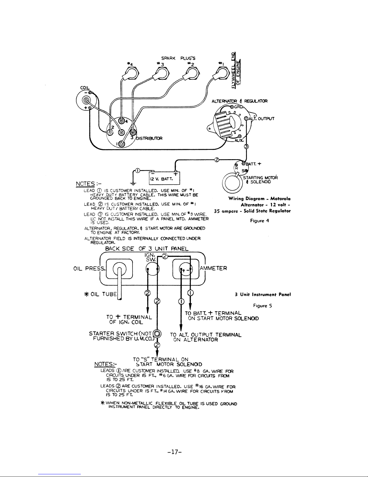
-4
SPARK PLUG'S
#3
#2
NOTES
:-
LEAD
CD
IS
HEAVY
DUTy BATTERY CASLE.
GROUNDED
LEAD @ IS
HEAVY
LEAD
ALTERNATOR,
ALTERNATOR
OUT
(3'\
IS
OC
NOT
IS
USE~.
TO
ENGINE
REGULATOR.
CUSTOMER
BACK
CUSTOMER
{ BATTERY CABLE.
Cu:;TOMER INSTALLED. USE
IN:;TALL THIS WIRE IF A PANEL
REGULATOR, ~ START.
AT
FACTORY.
FIELD
BACK SIDE
((---
OIL
PRESS.
*OIL
TUBE
TO T TERMINAL
OF
IGN. COIL
STARTER SWITCH (NOT a
FURNISHED BY
INSTALLED. USE MIN.
TO
ENGINE.
INSTALLED. USE MIN.
IS
INTERNALLY
OF 3
THIS
MOTOR
CONNECTED
UNIT
I~N~
r-®~==+--.
~
U.
M.CO.
OF
MIN.
ARE
MUST
OF
MTD.
"I
BE
OF
MI
#8
WIRE.
AMMETER
GROUNDED
UNDER
WIRE
A\NEL
( 1 I
TO
BATT.
ON
TO
ALT.
OUTPUT TERMINAL
ON
ALTERNATOR
35
"\
AMMETER
+ TERMINAL
START
MOTOR
Wiring
ampere
Diagram -Motorola
Alternator -12
- Solid
State
Figure
3
Unit
Instrument
Figure
SOLENOID
volt -
Regulator
4
Panel
5
NOTES:- S
LEADS
CD
lIRE
CIRCUITS
15
TO
25
<Zl
LEADS
*
ARE
CIRCUITS UNDER IS
IS
TO
25
WHEN
NON-METALLIC
INSTRUMENT
TO
CUSTOMER
UNCER
FT.
CUSTOMER
FT.
~NEL
"S"
TERMINAL
TART
15
FT.,
FT
DIRECTLY
MOTOR
INSTALLED. USE
*6
INSTALLED,
••
#14
FLEXIBLE
ON
SOLENOID
GA.
\MRE ~ ClRCUTS
USE
GA.
WIRE
OIL
TO
ENGINE.
-17-
#8
GA. WIRE
#16
GA.
FOR
TUBE IS USED
WIRE FOR
CIRCUITS
~
FR(J.1
FROM
GROUND
Page 29

Figure 8
TO ALT. OUTPUT TERM.
TO DIST.HTERM.
,GROUND
~P~RATURE
.,
TO + TERM.
TO·S"TERM.
BAT
TO
ENGINE
AT
COIL
TO
ENG.
BOCK
01
L PRESSURE SENDER BLUE
OF
IGN.
COIL
OF
START
+
TERM
ON START MOTOR..sQL
HARNESS
Figure 9
TO ALT. OUTPUT
,TO DIST.HTERM.
GROUND
~
~
OIL PRESSURE
Tt:
TERM.
TO
·S"TERM.
TO
BAT
+ TERM ON START
ENGINE
TERM.
AT
COIL
TO
ENG.
BLOCK
TEMPERATURE
OF
IGN
COIL
OF
START
HARNESS
ON
SENDER
MOTOR
ON
SENDER
SENDER
MOTOR
ALT
PURPLE
SOL.
ALT
PURPLE
SOL.
MOTOR
ORG.
GRAY
BLACK
TAN
WHITE
RED
~
CONNECTOR
AT
ENGINE
f...lI::Ull..
CONNECTOR
AT
PANf!
Electric Instrument Panel with Tachometer
ORG.
GRAY
BLACK
TAN
BLUE
WHITE
SOL
RED
~
CONNECTOR
AT
ENGINE
f...lI::Ull..
CONNECTOR
AT
PANEl
INST. PANEL
GRAY
TAPED
DO
BLACK
LESi
NOT U
GROUNDED
BACK
OF PANEL
AMMETER
TO
AMMETER
~
INST PANEL
THRU TACH.
IS
MT.
GROU"-OEP
RK.
Electric Instrument Panel less Tachometer
-18-
INST. PANEL
Page 30

I
....
-.0
I
NOTE:
BACK
SmEOF 5 UNIT
PANEL
"I>.'
SIZE
WIRE
"B"
SIZE
----
WIRE
=0'
liEGULATOfl
MUST
E'E
I/()I
JNTED
\EP,!CALL\
WITH TERMINALS
D0W",
REGULATOh
L-
________
~~
GEN.
IiGl..
hD.
() I
,"
ALTERNATCI'-
GENERATOF
12-V,-ro
AMp,
GROUNDED
TO
ENGINE
AI
FAC~ORY
FOR NEGATIVE GR0UND SYSTEM
REcur·il-'£~'IJJ::r
HINIMt:M
/Ii'I!'tE
SIZE
FOR
CO:SKECTING
rtLTERNATuR & REGl'LATuR
Total
Length
uf
11I~IISi2.e
I
"BuSize
Circuit
In
Jo"eet
...
lire
'.-11re
151
or
less
118
1116
15'
to
25'
.6
TfIT4
"C-;-E - IMPORTANT
BATTERY
Af'.,1)
REGULATOR MUST
81=:
GROUNDED
T0
Ef\'G
INE
BY
CI.:'STVMER
BEFORE OPERATING
THE
ENGINE.
Fig.
21
Wiring
Diagram -Leece
Neville
Alternator -lZ
Volt,
60
Amp
BACK
SIDE
~UNlT
PANEe
r \
o
TACHOMETER
TO
'*'
HEAT
GROUNDED
TO
"
~
ENG.
BY
CUSTOMER
______
...J
....
S
.,"
B
IS.
IZE
A SIZE WIRE
,\G~WON
u
W'RE
~
DISTRIFIlj
ror.
VOLTAGE
REGULATOR
MOUNT
SEPARATE
FROM
ENG.
AND IN
VERTICAL POSITION
GROUND'
l~
"-
TERMINAL
=",
,\:-ARM,
TERMINAL
GROUND
10)
'f.'
SIZE
WIRE
ENG.
AT
FACTORY
NOTE: IMPORTANT
WIRE
It CAI:ll.E
SIZES
FOR
12
V.
CIRCUIT
GA.NO,
LENGTH
GENERATOR
12
6'OR
LESS
10
6'TO
10'
Il
!CiTO
15'
6
15'
TO
25'
5
2.5'TO
~O'
STARTING
0
6
OR
LESS
CIRCUIT
I
00
6'TO 7 1/2'
CUG
7
V2'
TO
10'
,HORN
10
LIGHTING
10
MAX
OF
FOUR
21·C.P.
LAMPS
PER
CIRCUIT
UGNITION
12
NITH
I COIL
REPOLARIZI~G
~
After
reconnectin~
leads
and
before
startin~
the
engine,
momentari
ty
connect
a jump
lead
between
the
"BAT"
terminal
of
the
reeulator
and
the
IIAII
terminal
of
the
eenerator.
This
allows
a momentary
sur~t'
of
current
to
flow
through
the
2enerator,
correctly
polarizin.2
it.
Reversed
polarity
may
result
1n
vibratine
arcinsz: and burntn@:
of
the
cutout
relay
contact
points.
BATTERY
...
t\D
REGUl...ATOR
r.llST
BE
GRLtUt\DED
TO
EKGI:SE
BY
Cl!ST0H£R
BEFIJRE
OPERAT
ING
THE
ENGI~E.
~hen
non-metalic
flexible
oil
tube
or
heat
indicator
connection
is
used,
ground
enp.ine
d1.rect
to
instrument
pane
1.
RecolTlTlended minimum
wire
size
for
connectin~
generator
and
re2.ulator
IS'
to
2S' I #6
liB"
size
wire
016
lifli
12
VOLT IGNITION WIRING
DIAGRAM
\\ITH
5
UNIT
PANEL
FOR
NEC-;ATlliE
GROUND
SYSTEM
Fig.
21-A
Wiring
Diagram -Auto-Lite
Generator
- 12
volt,
12
amp.
Page 31

I,zj
......
(Jq
•
I\)
I\)
~
......
I;
......
t:!
(Jq
~
......
I;»
(Jq
I;
~
I
en
I\)
d-
O
P-
I
•
.....
I\)
~
0
.....
d-
I;»
t:!
P-
.....
I\)
<l
0
.....
d-
I\)
+:-
>
e
It::!
•
THE
ELECTRICAL
SYSTEM
OF
ENGINE
MUST
HAVE
NEGATIVE
GROUNDED
BATTERY
WHEN
12
VOLT
24
AMP.
GENERATOR
IS
USED.
REGULATOR
FURNISHED
WITH
STANDARD
12
VOLT
GENERATOR
CAN
BE
EITHER
POSITIVE
OR
NEGATIVE
GROUND.
FIELD
TERMINAL
GROUND
TERMINAL
'-ARMATURE
TERMINAL
-
--
REGULATOR
IS
TO
BE
MOUNTED
SEPARATE
FROM
ENGINE
AND
PREFERABLY
IN A
VERTICAL
POSITION
------
-
----,
GR.
TO
-
--
- - --.
ENGINE
1
--,
I
I
I I
r-
I I ,
L
-l-Ji'--
, I
L_
1
__
I
I
I
•
II
POSe
Ail.
__
J
STRIP
WIRING
DIAGRAM
FOR
STANDARD
12
VOLT
BATTERY
CHARGING
GENERATOR
(AUTO-LITE)
NEG.
12
VOLT
BATTERY
WIRING
DIAGRAM
FOR
12
VOLT
24
AMP.
HIGH
CHARGE
RATE
GENERATOR
AS
USED
ON
UJ
AND
BN
(DELCO-REMY)
-
-
REPOLARIZING
GENERATOR
After
reconnecting
leads
and
before
starting
the
engine,
momentarily
connect
a
jumper
lead
between
the
"BAT"
terminal
of
the
regulator
and
the
"A"
termi-
nal
of
the
generator.
This
allows
a
momentary
surge
of
current
to
flow
through
the
generator,
correctly
polarizing
it.
Reversed
polarity
may
result
in
vibrating,
arcing
and
burning
of
the
cutout
relay
contact
points
•
Page 32

INSTALLATION
DRAWl
NGS
------~----------------~BLUE
BORE
S
K["fWAY
~
Fig.
23
I 2
lZ2 :
II ~ :
3a
! I
l
16
L a
JACKET
FOR ~ BOLT
i
~
----------------------------ATOMIC
i
i.
8!J:.j.
8~'"
FOUR
t-----I7"*
-8li--+----
TWIN
SERIES----------------~------
i PIPE
TAP
WATER
OUTLET
1"<
I 1
~
~~
3y
..
13~
-?I~-
3~
13
-
..
16
SERIESi--------------------------
----I
IS
BORE
i-
KtYWAY
'~
i X i
Fig.
--4-----
~-----Z6!---------------l
'7
51&---'
1
DIRECT
DRIVE
25
Fig.
1--
~.-
~---
I i
I i
~
I
24
17
*
-------
sli
----~
~-
. - .
a.f6-~
5f~-'"
(I
I
w.o.
IEXI1.
1--,
.r
-21-
Page 33

----------------------~ATOMIC
FOUR
SERIES
(Cont.)----------------------
AQUA-PAX
V-DRIVE
1:1,
--------------------------UTILITY
1.29:1,
1.67:1
Fig.
FOUR
27
&
2:1
RATIO
SERIES--------------------------
tPIPE
WATER
Fig.
TAP
OUTLET
26
-rP1Pr
TAP
_TtR
OUTLET
REDUCTION
DRIVE
-22-
DIRECT
Fig.
.)4~
28
3
DRIVE
Page 34

----------------------------SUPER-FOUR
SERIES---------------------------
DIRECT DRIVE
RIGID
MOUNTINGS
DIRECT DRIVE
RUBBER
MOUNTINGS
Fig.
30
Fig.
29
~
,
~~
~~
H
Y
fh
HI.
'
_
!r
3
.3IJ..-+--'-::~
L
-3
~
'---I~~-------'--12l--
I
REDUCTION DRIVE
RUBBER
MOUNTINGS
Fig.
32
--"'~
__
47------
- ..i..
REDUCTION DRIVE
RIGID
:
_,
'""
~I
__
-
-Il--
i
--~
MOUNTINGS
Fig.
31
-23-
Page 35

-----------------------UNIMITE
FOUR
SERIES--------------------------
2:1
REDUCTION
RUBBER
MOUNTINGS
Fig.
34
DRIVE
DIRECT
RUBBER
Fig.
DRIVE
MOUNTINGS
33
,CENTER
~'
H
I,
OF
-2"L._,.
1:
-24-
GRAVITY
j
I
AQUA-PAK
DRIVE & ALL
RUBBER
MOUNTINGS
Fig.
V-DRIVE
REDUCTION
35
RATIOS
Page 36

---------------------------------ARROW
8~Hl~8------------------
____________
__
Fig.
36
~llHA.UST
FOI1
2i
EITHEI1
TU&IN6
011
~NO
2Fp.
SIZE
STA-NU-TRAL
,---.----
-~~---
"'5
!--~-~
GEAR -DIRECT
DRIVE
Fig.
37
Fig.
ST.!-NU-TRAL
38
GEAR
II--~/
ST.!-NU-TRAL
1.88:1
/EXHAUST
FOR
2!
I i
54~--------
REDUCTION
EITHeR
TLJeINb
END
011
2Fp.
GEAR -2.44:1
-25-
5IZE
-~------
----~-----,
RATIO
----42~--
---~541--~-------
REDUCTION
RATIO
Page 37

------------------------------BLUEFIN
SERIES-----------------------------
EXHAUST
3 TUBING,
EITHER END
2~
PIPE
OR
FOR
TUBE
1.5:1
1.5:1
&
.8~O
I.S:I
&
2:1
OFFSET
RED.
I
1.3
2:1
2:1
OFFSET
RED.
DIRECT
MANUAL
i
OIA.
,
21
/ A
I!
~
/'
i
MIN.
BORE I
Ij
MAX.
BORE
f-.-----
REVERSING
<to
EXHAUST
BOLTS
-RUBBER
MOUNTS
OIA.
BOLTS
-SOLID
MOUNTS
CRANKSHAFT
41&.-----
DIRECT
HYDRAULIC
DRIVE
DRIVE
REVERSING
GEAR
EXHAUST
3 TUBING, 2-2'
GEAR
EITHER END
PIPE
OR
Fig.
FOR
TUBE-.------''-<d--,.-,~
I '
39
li~~;
,
12jb
I I
I I
I
I
\
~'MIN.
I~
MAX.
l-lIl-t::::j:::::::;;f--
BORE
BORE
Fig.
40
WATER
V-DRIVE
INLET I
~---------40&16--------------4
HYDRAULIC
GEAR -ALL
RATIOS
-26-
----~c_=~~=_:;:_:_7
RATIO
1.00
TO
1.46
TO
3.00TO I
Fig.
41
I
I
Page 38

-----------------------------MARLIN
SERIES-----------------------------
Fig.
42
~111--"~-i--:#-~
lOx
!
K~V
eNG!tL~WffiUI'!we(11-~2l
~!US;oP"'I~
STA-NU-TRAL
JaOx.\ m
1!0.5
KeV
"'4-~-
JiOalK~V
,
~--------~A
REVERSE
----46i----------------------~
GEAR,
1.88:1
REDUCTION
GEAR
Fig.
43
Fig.
STA-NU-TRAL
44
------se~
REVERSE
GEAR,
STA-NU-TRAL
-------------------------------1
2.44:1
~--------------------~5ge-------------------~
REVERSE
REDUCTION
~-------45i-----------------------~
GEAR,
3.32:1
GEAR
REDUCTION
GEAR
-27-
Page 39

------------------------------TARPON
SERIES-----------------------------
Fig.
I~
45
i
DIA.
/ADIA.IOLTS
~
Direct
EXHAUST
BOLTS
- RUBBER
CRANKSHAFT
MOUNTS
-SOLID
MOUNTS
Dr
ive
MANUAL
EXHAUST
REVERS
EXHAUST
fITH~R
END
ING
FOR
! MIN.
Ii
MAX.
GEAR
L"l\::::t:::t-
BORE
BORE
Fig.
46
L=----4~,-----------
1.05
OFFSET
1.5:1
RED.
1.5:1
HYDRAULIC
&
Direct
2:1
Drive
REVERSING
-28-
GEAR
Page 40

-----------------------------.KNIGHT
SERIES-----------------------------
._
•.
: I
I ) I H I
,60
, I
7~
I _ ~ _____
16
2~
4~'
~
. t
~J.:...::_-~R~A\.!!!N~K§.!SH~AfT~_=t,:;=j=-=r=~'R\l!_.-=:.:..J___I+_h___.
.... ' ..
.,: ....... :
ii'
, I
.
~
Fig.
____
~FOR
.-
'---
.---
i DIA.
/IDIA.IOLTS
RUBBER
___
"'I:<i.=EX="=AU=S""'T
BOLTS
-
RUBBER
4~----
flHAUST
0R
21
EXHAUST
ADIA.
BOLTS
-SOLID
MOUNTS
~---------4~----------------~
Direct
47
_____
MOUNTS
-SOLID
MOUNTS
41
I 9 4
MOUNTS
--"",,~
---31~----
f
-+_
~
71t •
Drive
MANUAL
3
REVERS
EITHf.R END
PIPE
OR
FOR
TUBE -
t~+--+::::
lr-':'-~
lJif
17
j
+-II-,------~
ING
1.05
OFFSET
1.5:1
GEAR
RED.\
\
1.6
,
'.~.I'
..
2:1
OFFSET
RED.
•
Direct
Fig.
48
Drive
HYDRAULIC
~--Z5~------~
~-----zzt----~
WATER
~---24§-------~
Fig.
49
V-DRIVE -HYDRAULIC
INLET
1.5:1
REVERSING
&
2:1
GEAR
~------lO~-+-+-~---~--
~-------44tl~-------~
GEAR -ALL
RATIOS
-29-
Page 41

----------------------~,LITTLE
nNUA.L
KING -V-B
REVERSING
SERIES------------------------
GEAR
Fig.
DIRECT
50
DRIVE
REDUCTION
Fig.
DRIVE,
51
1.5:1
RATIO
Fig.
REDUCTION
52
DRIVE,
2:1
RATIO
Fig.
REDUCTION
53
DRIVE,
2.5:1
RATIO
-30-
Page 42

------------------------LITTLE
KING
HYDRAULIC
SERIES
(Cont.)----------------------
REVERSING
GEAR
Fig.
DIRECT
54
DRIVE
'~
RED0CTION
Fig.
DRIVE,
55
1.5:1
RATIO
Fig.
REDUCTION
56
DRIVE,
2:1
HATI(
-31-
REDUCTION
Fig.
DRIVE,
57
2.5:1
RATIO
Page 43

------------------------~BIG
KING
- V-8
SERIES-------------------------
.
I.",·,
.~
..
. • , •.
".t
AA"'~
Fig.
DIRECT
HYDRAULIC
58
DRIVE
REVERSING
' ... -
-
-1-
------
~,~
....
"'"
--
-1
- 1
.'!>1.~
....
GEAR
-32-
REDUCTION
HYDRAULIC
DRIYJ<~,
2.~;:
REVERSING
1
P.ATIO
GEAR
Page 44
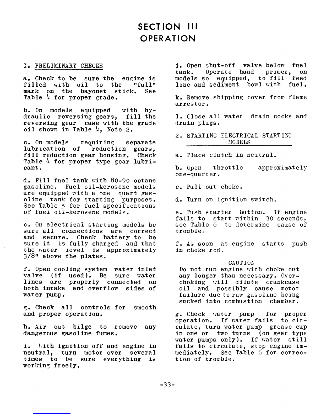
1.
PRELIMINARY
a.
Check
filled
mark
Table
b.
draulic
reversing
oil
c.
lubrication
fill
Table
cant.
do
gasoline.
are
oline
See
of
€c
sure
and
sure
the
3/8"
f.
valve
lines
both
water
g.
and
h.
dangerous
i.
neutral,
times
working
on
4
On
shown
On
models
reduction
4
Fill
equipped
Table
fuel
On
electrical
all
secure.
it
water
above
Open
intake
pump.
Check
proper
Air
With
to
be
with
for
models
reversing
for
fuel
tank
oil-kerosene
is
cooling
(if
are
all
out
ignition
to
freely.
oil
the
proper
gear
in
Table
of
proper
tank
Fuel
with
for
5
for
connections
Check
fully
level
the
used).
properly
and
operation.
bilge
gasoline
turn
be
CHECKS
sure
bayonet
equipped
case
requiring
gear
oil-kerosene
starting
fuel
plates~
system
controls
motor
sure
the
to
the
grade.
gears,
with
4,
Note
reduction
housing.
type
with
a
starting
charged
is
overflow
off
80-90
one
specifications
models.
are
battery
approximately
Be
connected
to
fumes.
and
over
everything
stick.
gear
water
sure
for
remove
engine
"full"
with
fill
the
grade
2.
separate
gears,
Check
lubr
octane
models
quart
purposes
models
correct
to
and
water
sides
smooth
engine
several
SECT
ION
III
OPERATION
j.
Open
tank.
is
See
hythe
i-
gas-
&
be
be
that
inlet
on
of
any
in
is
models
line
k.
Remove
arrestor.
1.
Close
drain
2.
STARTING ELECTRICAL STARTING
a.
Place
b.
Open
one-quarter.
c.
Full
d.
Turn
e.
Push
fails
see
trouble.
f.
As
in
choke
Do
any
choking
oil
failure
sucked
g.
Check
operation.
culate,
in
one
water
fails
mediately.
tion
so
and
plugs.
to
Table
soon
not
longer
and
or
pumps
to
of
shut-off
Operate
equipped,
sediment
shipping
all
water
clutch
throttle
out
on
starter
run
turn
trouble.
choke.
ignition
start
6
to
as
rod.
engine
than
will
possibly
due
to
into
combustion
water
If
water
two
only).
Circulate,
See
valve
hand
bowl
cover
drain
MODELS
in
neutral.
switch.
button.
~ithin
determine
engine
CAUTION
with
necessary.
dilute
raw
gasoline
pump
water
pump
turns
stop
Table
below
primer,
to
fill
with
from
cocks
approximately
If
30
seconds
cause
starts
choke
Over-
crankcase
cause
fails
(on
If
6
water
motor
being
chamber.
for
to
grease
gear
engine
for
correc-
fuel
on
feed
fuel.
flame
and
engine
r
of
push
out
proper
cir-
cup
type
still
im-
-33-
Page 45
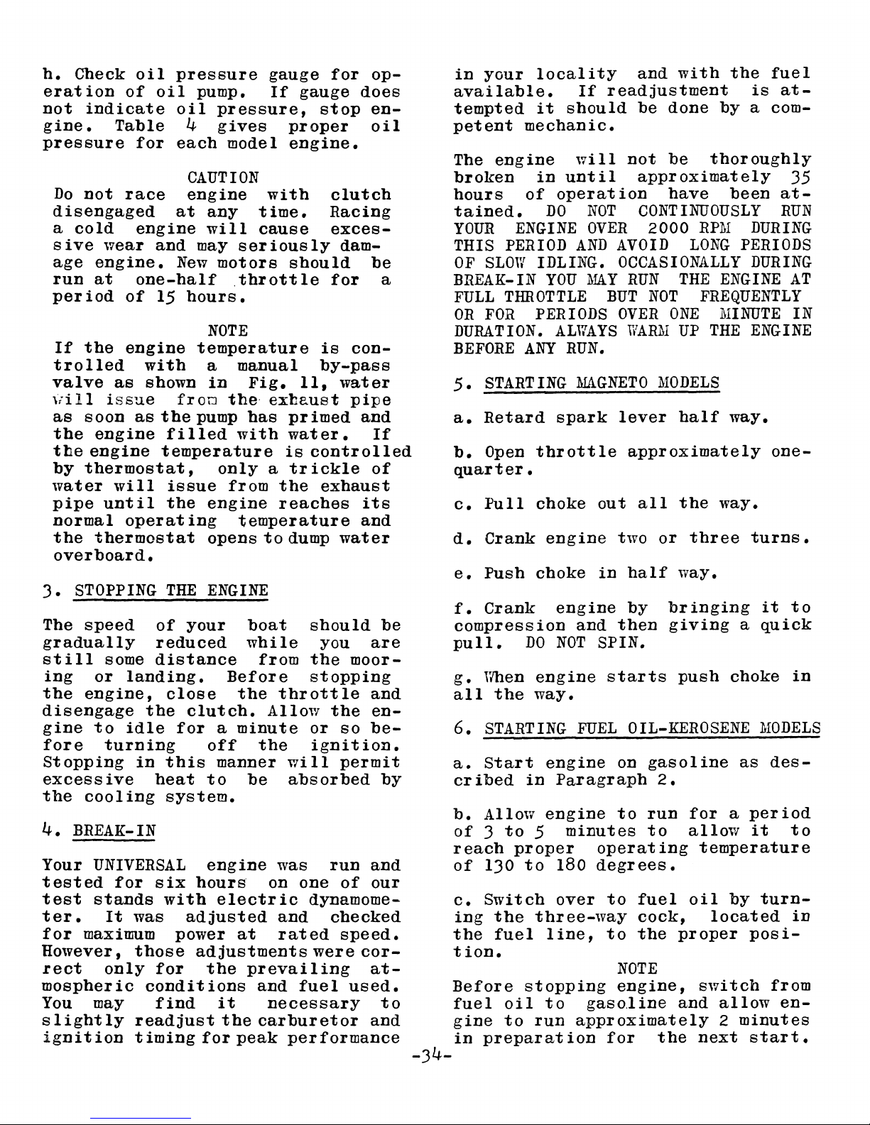
h.
Check
eration
not
pressure
3.
still
the
disengage
the
4.
Your
tested
test
ter.
for
However,
rect
mospheric
You
slightly
indicate
gine.
Do
disengaged
a
sive
age
run
period
If
trolled
valve
\iill
as
the
tile
by
water
pipe
normal
the
overboard.
The
gradually
ing
gine
fore
Stopping
excessive
BREAK-IN
igni t ion
Table
not
cold
wear
engine.
at
the
as
issue
soon
engine
engine
thermostat,
will
until
thermostat
STOPPING
speed
some
or
engine,
to
turning
cooling
UNIVERSAL
for
stands
It
maximum
only
may
oil
pressure
of
oil
pump.
oil
4
for
each
CAUTION
race
engine
one-half
of
engine
with
as
operating
landing.
idle
in
was
those
readjust
timing
engine
at
and
may
New
15
hours.
temperature
shown
froD
the
pump
filled
temperature
issue
the
THE
of
your
reduced
distance
close
the
clutch.
for
this
heat
system.
six
hours
with
adjusted
power
adjustments
for
conditions
find
gauge
If
pressure,
gives
model
with
any
will
NOTE
a manual
in
engine
opens
ENGINE
off
to
engine
the
for
time.
cause
seriously
motors
.throttle
Fig.
the
exbaust
has
with
only
a
manner
electric
it
the
a
from
Before
minute
peak
the
reaches
temperature
to
boat
while
from
the
throttle
Allow
the
be
was
on one
and
at
rated
prevailing
and
necessary
carburetor
for
gauge
stop
proper
engine.
clutch
Racing
exces-
dam-
should
for
is
con-
by-pass
11,
water
pipe
primed
water.
is
controlled
trickle
exhaust
dump
will
absorbed
per
water
should
you
the
moor-
stopping
the
or
so
ignition.
permit
run
of
dynamome-
checked
speed.
were
fuel
used.
formance
op-
does
enoil
be
a
and
If
of
its
and
be
are
and
en-
be-
by
and
our
cor-
at-
to
and
in
available.
tempted
petent
The
broken
hours
tained.
YOUR
THIS
OF
BREAK-IN
FULL
OR
DURATION.
BEFORE
5.
a.
b.
quarter.
c.
d.
e.
f.
compression
pull.
g.
all
6.
a.
cribed
b.
of 3 to
reach
of
c.
ing
the
tion.
Before
fuel
gine
in
-34-
your
SLOW
FOR
STARTING
Retard
Open
Full
Crank
Push
Crank
When
STARTING
Start
Allow
130
Switch
preparation
locality
it
should
mechanic.
engine
in
until
of
operation
DO
ENGINE
PERIOD
IDLING.
YOU
THROTTLE
PERIODS
ALWAYS
ANY
RUN.
spark
throttle
choke
engine
choke
engine
DO
NOT
engine
the
way.
engine
in
Paragraph
engine
5
minutes
proper
to
180
over
the
three-way
fuel
oil
to
line,
stopping
to
run
and
with
If
readjustment
be
done
will
AND
MAGNETO
and
FUEL
approximately
not
be
approximately
have
NOT
OVER
:MAY
gaso.line
CONTINUOUSLY
2000
AVOID
OCCASIONALLY
RUN
BUT
OVER
WARM
lever
approximately
out
two
in
half
by
then
SPIN.
starts
OIL-KEROSENE
on
to
operating
degrees.
to
to
NOTE
engine,
for
THE
NOT
ONE
UP
MODELS
half
all
the
or
way.
bringing
giving
push
gasoline
2.
run
to
fuel
cock,
the
proper
and
the
LONG
three
for
allow
oil
the
fuel
is
at-
by
a com-
thoroughly
35
been
RPM
ENGINE
FREQUENTLY
MINUTE
THE
way.
way.
choke
a
temperature
by
located
switch
allow
2
next
at-
RUN
DURING
PERIODS
DURING
AT
IN
ENGINE
one-
turns.
it
to
a
quick
in
MODELS
as
des-
period
it
to
turn-
in
posi-
from
en-
minutes
start.
Page 46

LUBRICATION
Table
4
REQUIREMENTS
MODEL
NAME
Blue
Jacket
Atomic
Utility
Super-Four
Unimite
Arrow
Bluefin
Marlin
Tarpon
Knight
Little
Big
Four
King
King
The
engines
gears),
gine
same
and
cated.
Twin
Four
Four
reduction
are
oil
S.A.E.
do
not
with
lubricated
supply
number
have
Surrounding
Air
Over
Maximum
gears
Temp.
90
S.A.E.
S.A.E.
S.A.E.
S.A.E.
S.A.E.
S.A.E.
S.A.
S.A.E.
S.A.E.
S.A.E.
S.A.E.
S.A.E.
Note
of
manual
and,
of
to
be
S.A.E.
0
and
F.
Service
JO
JO
40
40
JO
JO
E.
JO
JO
JO
JO
JO
JO
1
these
type
from
therefore,
oil
as
separately
VISCOSITY
ENGINE
Average
engines
reversing
the
the
CRANKCASE
Surrounding
Air
Temp.
J2
to
90
Service
S.A.E.
S.A.E.
S.A.E.
S.A.E.
S.A.E.
S.A.E.
S.A.E.
S.A.E.
S.A.E.
S.A.E.
S.A.E.
S.A.E.
(on
main
en-
use
the
engine,
lubri-
NUMBERS
OIL
0
F.
JO
JO
JO
JO
JO
JO
JO
JQ
JO
JO
JO
JO
FOR
Surrounding
Air
Temp.
Below
Average
J2
S.A.E.
S.A.E.
S.A.E.
S.A.E.
S.A.E.
S.A.E.
S.A.E.
S.A.E.
S.A.E.
S.A.E.
S.A.E.
S.A.E.
We
do
high
These
ricating
thorough
impossible.
with
We
recommend
mineral
the
break-in
Engine
0
F.
Service
(Hot
20
20
20
20
20
JO JO
JO
JO
JO
JO JO
JO
)0
not
recommend
detergent
oils
have
qualities
break-in
oil
This
to
of
period.
respect
Average
p..ressure
Engine)
Lbs.
JO
45
45
45
JO
JO
JO
JO
Note
the
oils
such
is
seating
the
use
S.A.E.
Oil
J
use
during
extremely
that
is
difficult
particularly
of
of
JO
Herringbone
Reduct
Lubricant
Viscosity
.Separately
Lubricated
---
See
S.A.E.
S.A.E.
See
See
See
See
See
See
See
See
of
heavy-duty,
break-in.
good
correct
piston
a
weight
ion
Note
90
90
Note
Note
Notes
Note
Notes
Notes
Notes
Note
lub-
if
true
rings.
straight
during
Gear
S.A.E.
Number
#1
to
to
#1
#1
#1
#1
#1
#1
#1
#2
and
not
140
140
&
&
&
&
#2
#2
#2
#2
The
hydraulic
self-contained
engine
from
same
of
extreme
unusual
ditions,
if
is
When
ing
tion
system
The
cally
located
of
Oil
the
engine
S.A.E.
good
type
used.
engines
gear
gear
oil
the
level
marks
oil
quality
foaming
installation
"A"
and
of
level
by
means
on
hydraulic
reversing
pressure
oil
number
it
will
automatic
have
reduction
is
lubricated
the
hydraulic
should
the
shOi.lld
on
the
Note
2
and
independent
system
pressure
oil
non-foaming
is
encountered
or
further
both
be
of
the
side
at
reversing
be
maintained
bayonet
gear
is
(sealed
system).
as
in
the
operating
reduce
transmission
hydraulic
gear,
reversing
checked
bayonet
the
the
from
the
forward
gear
dipstick.
entirely
of
engine
type.
due
foaming
revers-
reducoiling
gear.
periodidipstick
housing.
between
the
off
Use
con-
oil
end
If
to
Most
standard
for
system
is a straight
tives
The
deSignated
line
service.
vice
and
service
Avoid
fically
can.
oil
the
Check
ing
prevent
to
Amounts
engine
engine
oil
which
an
and
heavy-duty,
engine
should
an
used
using
state
Watch
pan
and
mark.
the
and
the
of
model
is
companies
system
an
oil
oil
designated
mineral
intended
MS
and
service
An
oil
be
oil
deSignated
thereafter.
any
oil
the
the'
always
oil
level
several
overfilling.
full
mark
oil
and
mounted.
required
have
of
rating
is
intended.
oil
for
high
detergent
DG
for
and
designated
used
oil
CAUTION
times
the
during
that
service
level
keep
stick
while
Keep
on
angle
now
the
for
without
light
severe
general
for
does
rating
gauge
the
before
the
vary
at
adopted
ML
service.
oils
for
break-in
MS
not
oil
filling
oil
oil
with
which
service
In
this
service
addi-
are
gaso-
diesel
ML
ser-
and
specion
the
in
the
up
start-
level
stick.
the
the
a
DG
to
to
-35-
Page 47

Table
5
7.
OPERATION
Several
used
types
on
operation,
all
cases.
tion
a.
position
IV,
Moving
(toward
transmission
b.
Moving
position
places
the
drive.
c.
Moving
position
neutral
to
the
8.
OPERATION
a.
The
and
propeller
hydraulic
basically
multiple
with
disc
a
planetary
NO.
CYLINDERS
2
4
6
V-8
V-8
V-8
OF
OF
LEV
SEVH
NKEV
STANDARD
GEAR
of
reversing
UNIVERSAL
however,
See
Paragraph
for
detailed
the
lever
engine)
in
forward
the
lever
(away from
transmission
the
lever
puts
the
no power
shaft.
OF
HYDRAULIC
GEARS
reversing
a
hydraulically
clutch
hydraulically
reversing
STANDARD
1-2
1-2-4-3
1-5-3-6-2-4
1-2-7-5-6-3-4-8
1-2-7-5-6-3-4-8
1-5-6-3-4-2-7-8
REVERSING
gears
engines.
is
the
same
6,
operation.
to
the
forward
places
drive.
to
the
the
to
transmission
is
in
gear
engine)
in
reverse
the
center
delivered
REVERSING
gear
operated
comb.ination
operated
train.
FIRING
are
The
in
Sec-
the
stern
in
is
The
ORDER
ROT.
gear
top
IV
(1)
cover,
the
(2)
position
in
()
or
mission
b.
is
the
almost
ment
This
speeds.
necessary
tain
In
at
preferably
range.
engine
the
OPPOSITE
1-4-2-6-3-5
1-8-1+-3-6-5-7
1-8-4-3-6-5-7-2
1-8-7-2-4-.3-6-5
positions
cover.
for
detailed
Moving
to
See
the
the
transmission
Moving
places
reverse
Moving
"N"
The
such
drive.
the
position
in
neutral.
design
that
forward
instantaneous
of
the
shifting
condition
For
to
good
fact,
low
shifting
it
speeds,
in
Shifting
speeds
boat,
engine
are
Paragraph
operation.
lever,
"F"
the
lever
places
of
the
and
exists
this
race
is
advisable
below
the
will
ROT.
-2
stamped
6,
on
the
position
in
forward
lever
the
the
operation
reverse
reason
the
characteristics.
800
at
avoid
reversing
to
transmission
to
the
the
reversing
drives
with
the
control
even
it
engine
1400
to
conservative
damage
on
Section
places
drive.
the
center,
trans-
gear
of
both
move-
lever.
at
is
to
to
shift
RPM,
1000
gear,
the
top
"R"
is
low
not
ob-
and
RPM
to
-)6-
Page 48

shafting
the
shock
engine
9.
COLD
Special
when
operating
weather
tion
and
engine.
are
a.
listed
Keep
prevent
starting
b.
Be
sure
free
in
c.
See
d.
run,
of
the
Substitute
Table
When
drain
block,
before
Starting
pump
drive
sure
frozen
shaft
the
thawed
start
the
and
of
speeds.
WEATHER
precautions
to
insure
to
Some
below:
battery
freezing
power.
fuel
water
fuel
system
4.
engine
all
water
the
water
an
will
or
water
out
engine.
propeller
rapid
OPERATION
engines
efficient
prevent
items
to
fully
and
lines
to
prevent
due
lighter
is
stopped
water
pump,
has
engine
probably
damage
pump
before
caused
shifting
must be
damage
be
considered
charged
to
get
and
to
engine
from
and
water
time
to
with
the
is
thoroughly
attempting
at
high
taken
in
cold
opera-
to
the
maximum
tanks
are
stoppage
freezing.
oil.
after
cylinder
lines
freeze.
the
water
break
the
gears.
by
to
a
Be
to
b.
Manifold
Open
and
c.
drain
drain
Water
Pump
Water pumps
ceptible
The
pump
A
drain
tom
of
der
engines
pumps
d.
Lubrication
The
oil
should
minated
acid
not
cause
quarts
pumped
the
motor
Doing
film
rust
e.
Cylinders
Remove
or
two
should
plug
the
and
pan
be
oils
present
of
through
by
so
of
oil
preventative.
the
ounces
combustion
to
give
cylinder
the
sure
cing
lubr
walls,
engine
of
distribution
spark
cocks
watet
to
pump
are
to
in
from
are
particularly
damage from
be
carefully
is
provided
housing.
equipped
drain
System
and
lubrication
drained
so
that
in
the
corrosion.
new,
clean
the
hand
will
or
distribute
which
spark
plugs
of
chamber
icat
ion
over
a few
plugs.
exhaust
the
loosen
of
old
old
Two
oil
system
electric
will
new
and
of
to
oil
each
piston
valves.
before
manifold
manifold.
freezing.
drained.
on
the
Six
cylin-
wi
th
Jabsco
end
system
or
conta-
moisture
oil
or
should
by
turning
starter.
a
act
and
pour
into
cylinder
rings,
times
repla-
sus-
bot-
cover.
or
will
three
be
clean
as
a
one
the
Turn
to
be
e.
Extra
may
be
vaporization
cold
f.
to
fore
10.
starts.
Give
warm
subjecting
PREPARING
Neglect
winter
and
costly
be
carefully
plete
a.
Cylinder
Open
block.
choking
required
the
up
in
preparing
storage
damage. The
protect
all
drain
Leave
in
engine
both
ENGINE
may
covered
ion
Block
drain
or
to
get
the
sufficient
water
it
to
lead
from
cocks
cocks
external
sufficient
manifold
and
heavy
FOR
STORAGE
an
engine
to
engine
to
give
rain
and
on
open.
heat
for
time
oil
be-
loads.
for
annoying
shoulu
com-
snow.
cylinder
-37-
f.
Valves
Remove
oil
valves
oil.
seal
g.
See
and
breather
Distributor
that
well
should
trance
h.
Starting
The
start
against
pinion
clean
light
well
be
sealed
and
the
valve
and
Replace
the
lubricated.
be
ta~en
of
moisture
Motor
ing
motor must
rain
and
and
oil.
and
screw
covered
The
lubricated.
to
Tappets
tappet
tappets
tappet
tube
end
distributor
to
prevent
during
snow. The
shaft
with
bearings
The
motor
prevent
covers
with
clean
covers
with
tape.
is
clean
Special
the
storage.
be
protected
starter
should
a
film
should.be
should
corrosion
and
and
care
en-
be
of
of
Page 49

commutator
the
commutator.
i.
Generator
Oil
bearings.
to
prevent
and
brushes.
Seal
corrosion.
Do
moisture
not
tight
oil
~.
Battery
Remove
dry
place.
cbarged
cbecked
cbarging
long
be
to
battery
clean
prevent
battery
and
Battery
wben
placed
periodically.
may
be
life.
and
coated
corrosion.
store
sbould
in
storage
desirable
Terminals
witb
in a warm
be
fully
and
Occasional
to
pro-
sbould
vaseline
1.
GENERAL
a.
UNIVERSAL
water
in-head
dels
ent
of
of
b.
of
fuels
cylinders,
the
While
engine
steps
power
to
cycle.
intake,
cooled,
THEORY
engines
"L"
engines.
the
engine
and
may
the
engine
remains
operating,
goes
through
complete
These
compression,
haust.
(1)
Intake
As
the
cylinder,
Stroke
piston
tbe
travels
intake
Vacuum formed on
inder
ment
mixture
the
cylinder
(2)
As
intake
and
between
the
(3)
When
top
started
spark
explode.
caused
of
the
from
intake
by
piston
tbe
manifold,
compression
Compression
the
tbe
cylinder
Power
the
of
piston
and
fuel
the
Stroke
piston
its
exbaust
mixture
top
head.
stroke
down, a
causes
tbe
This
carburetor,
Stroke
explosion
THEORY
OF
OPERATION
are
four
bead
While
may
basic
top
the
travels
of
has
fuel
and
various
·use
vary
in
tbe
a
four
four
one
working
steps
power
down
valve
of
downward move-
draws
and
chamber.
up,
valves
is
compressed
the
piston
reached
and
has
properly
mixture
drives
SECTION
cycle,
valve-
mo-
differ-
number
operation
same.
cycle
separate
or
are:
and
ex-
in
the
opens.
the
cyl-
tbe
fuel
through
into
tbe
both
close
and
the
just
timed
tbe
to
OF
IV
OPERATION
piston
by
by
cranksbaft
(4)
The
wben
upward
the
burned
combustion
baust
system.
c.
of
After
stroke,
with
tinues
operation.
2.
The
Utility
equipped
system.
in
volt,
ignition
a.
(1)
the
coil,
plugs.
down
the
sudden
means
Exhaust
fourth
the
travel.
exhaust
gases
manifold
The
exbaust
one
complete
completion
the
the
as
THEORY
Blue
Jacket
Models
All
this
book
battery
system.
Battery
Ignition
The
ignition
battery,
ignition
and
of
to
Stroke
and
piston
are
chamber,
cycle
intake
long
OF
IGNITION
with
other
have
Operated
the
power
tbrust
is
connecting
the
propeller
last
stroke
again
During
valve
opens
forced
into
and
stroke
out
marks
operating
of
repeats,
stroke
as
the
SYSTEMS
Model
BNM
a
and
~agneto
models
either
operated
Electrical
System
system
distributor,
switch,
developed
transmitted
rod
sbaft.
occurs
starts
tbis
period
and
out
of
tbe
tbe
exbaust
the
cycle.
the
exhaust
starting
and
engine
AFT
is
and
BNMR
ignition
described
a 6
electrical
consists
ignition
and
spark
and
its
the
tbe
ex-
end
con-
in
tbe
are
or
of
12
-38-
Page 50

(2)
Two
and
secondary,
system.
cui t cons
voltage
coil
winding
secondary
sists
the
cap,
of
coil,
high
plugs.
(J)
In
operation,
battery
ing
of
the
the
breaker
tor.
of
flow
thus
and
Periodic
the
of
causing
collapse
around
coil.
field
the
high
cuts
ignition
voltage
Current
igni t ion
the
in
to
(4)
distributor
the
distributor
the
spark
Arcing
points
by
the
around
,coil
denser
the
is
connected
separate
make
The
primary
ists
of
distributor
and
high
the
tension
secondary
distributor
tension
passes
to
ignition
pOints
opening
breaker
current
to
an
of
the
the
primary
This
fluctuating
the
secondary
coil,
to
from
coil
the
is
then
plug.
across
of
the
distributor
collapsing
primary
reduced
circuits,
up
the
low
tension
the
battery,
points,
condenser.
circuit
wiring,
current
the
primary
coil,
of
the
and
points
start
alternate
magnetic
winding
causing
be
induced
secondary
passed
rotor
cap
the
magnetic
winding
by
use
across
primary
ignition
primary
winding
rotor
and
from
through
distribu-
closing
causes
and
build-up
of
magnetic
winding
a
in
of
through
to
contacts
and
finally
low
voltage
caused
of
of a con-
the
points.
cir-
low
The
con-
of
and
spark
the
wind-
the
stop,
field
the
of
very
it.
the
field
the
(2)
The
high
used
on
UNIVERSAL
secondary
great
number
superimposed
ing.
circuited
device,
the
the
has
is
due
the
energy
The
during
field
energy
reached
opened,
to
the
magnetic
of
primary
by
in
discharged
and
due
to
secondary
crease
sulting
turns,
in
voltage
high-tension
distributed
(J)
Because
a magneto
engine
is
available
engine
gine
is
would
voltage
the
spark
vent
netos
this
used
pulse
couple
and
at
its
speed
starting
varies
speed,
speeds,
hand
sometimes
sufficient
plug
from
coupling
the
the
period.
tension
winding,
of
turns
upon
the
means
the
the
armature
in
the
a maximum,
and
at
the
rotat
ion
field
the
primary
through
the
ratio
a
results.
to
the
the
spark
directly
an
increase
at
high
such
cranked,
fail
gap.
occurring,
are
equipped
which
magneto
same
of
time,
rotation
type
magneto
engines
comprIsIng
of
fine
primary
winding
of
an
auxiliary
is
building
coil.
primary
this
same
of
the
is
removed.
circuit
circuit
instant,
armature,
winding
the
secondary,
of
primary
considerable
The
current
spark
is
plugs.
intensity
with
of
speeds.
as
to
In
when
the
to
spark
order
the
magneto
produce
to
the
with
serves
to
the
engine,
accelerate
during
has
a
a
wire,
wind-
short
uP.
of
When
The
is
to
inre-
then
of
the
energy
At low
en-
a
across
premag-
an
im-
to
the
b.
Magneto
(1)
Magnetos
tion
are
of
are
of
usually
energy
used
engines
tion
of
cylinder
construction
magnetic
rotate
within
breaker
which
serves
current
Ignition
are
the
electric
used
required
on some
to
furnish
the
models
compressed
chambers.
comprise
field,
that
and a distr
to
carry
to
the
spark
Systems
a
special
where
is
energy
The
armatures,
field,
ibut
plug.
applica-
generator
the
output
small.
of
UNIVERSAL
for
gases
elements
a
permanent
a
circuit
ing
mechanism
the
generated
and
They
igni-
in
the
which
of
J.
All
with
system.
a.
(1)
system
necessary
gine
accessories
of
those
lubrication
-J9-
LUBRICATION
UNIVERSAL
a
Full
The
full
Pressure
full
pressure
pressure
effectively
moving
with
the
mounted on
the
engine.
models
which
of
SYSTEM
engines
Lubrication
lubricates
parts
exception
See
require
reduction
are
equipped
lubrication
System
lubrication
of
the
of
those
the
outside
Table
4
separate
gears.
all
en-
for
Page 51

(2)
The
cated
in
through
forced
and
holes
to
camshaft
in
cylinder
lubrication.
cylinder
for
the
valve
plied
a
to
drilled
crankshaft.
gears
their
(J)
sure
oil
are
own
All
models
system
pressure
adjusted
See
Table
(4)
Six
and
and.
the
Super-Four
ped
with
oil
pump
aDd
cooled
cooling
on
Super-Foul'
cooler
rectly
in
the
system.
short
from
event
clogged.
4.
FUEL
The
tank,
fuel
(except
fuel
on
carburetor,
intake
tank
the
tor
through
the
chamber
a.
(1)
~o
line
to
speeds.
type
manifold.
enters
strainer
where
valves,
Fuel
The
supply
from
meet
and
the
of
Pump
purpose
engine
This
gear
an
the
all
driven
oil
intake
main,
bearings;
the
wall,
Drilled
block
tappets.
the
reversing
hole
Hydraulic
separately
oil
supply.
are
regulator
for
proper
4
for
eight
oil
coolers.
is
circulated
by
water
models)
circuits
the
SYSTEM
system
line,
Blue
flame
the
and
it
is
intake
and
the
an
adequate
the
tank
pump
is
operated
oil
base,
screen.
connecting
connecting
piston
and
holes
provide
gear
in
the
lubricated
using
the
equipped
which
oil
proper
setting.
cylinder
models
Oil
to
trom
A
by-pass
built
the
pump
the
to
the
cooler
consists
strainer,
Jacket
Twin
arrestor~
Gasoline
fuel
into
pump
the
vaporized
manifold,
into
the
cylinder.
of
the
fuel
amount
to
the
requirements
is
of
the
by
pump,
draws
Oil
rod
through
rods
wrist
in
pin
the
lubrication
Oil
is
sup-
through
end
of
the
reversing
from
full
pres-
with
may
pressure.
models
are
equip-
from
the
the
the
cooler
engine
(except
into
oil
oil
the
di-
line
becomes
of
fuel
pump
models),
and
from
the
through
carbure-
and
drawn
through
combustion
pump
of
gaso-
carburetor
at
all
diaphragm
a
plunger
looil
is
jet
for
an
be
is
working
camshaft.
(2)
As
the
reached,
causing
a vacuum
The vacuum
tank,
into
The
pressed
through
the
return
diaphragm
gasoline
into
(J)
the
float
the
ther
With
needle
is
this
the
but
rather
the
in
buretor
take
thus
engine
b.
The
to
the
After
carburetor
mechanism
needle
passage
the
valve
created
back
rocker
is
taken
than
diaphragm.
the
fuel
demands,
longer
maintained
operating
Carburetor
function
furnish
gasoline
the
proper
ting
conditions,
throttle.
gasoline
all
speeds,
into
with
small
air.
preheated
before
through
c.
A
flame
inlet
the
by
backfiring
A
special
being
the
Flame
Arrestor
arrestor
of
possibility
off
the
an
high
plunger
eccentric
point
above
draws
gasoline
the
fuel
chamber
stroke
releases
spring,
through
the
carburetor
several
diaphragm
bowl
rises,
valve
of
and
fuel
carburetor
closed,
on
the
diaphragm.
pressure
on
arm movement
up
by
being
As
pressure
chamber
the
strokes"
in
conditionG.
of
the
the
correct
and
air
to
proport
To
is
accurately
ion
accomplish
atomized
particles,
The
fuel
in
the
drawn
intake
into
valve.
attached
the
carburetor
of
fire
through
element,
of
the
is
forced
the
diaphragm.
inlet
of
valve
the
expelling
outlet
bowl.
fills
thus
stopping
from
bowl
the
filled
back
the
diaphragm~
continues,
the
transmitted
because
diaphragm
Fuel
accordance
carburetor
mixture
the
for
engine
all
idling
thiS,
metered
or
broken
and
is
vaporized
intake
the
to
eliminates
being
the
carburetor.
consisting
on
the
cam
is
down,
from
the
and
pump.
the
com-
valve
strokes,
and
its
seating
fur-
pump.
and
pressure
i~7i
th
linkage,
to
reduces
of
car-
will
flow
is
with
is
of
in
opera-
to
full
the
at
up
mixed
and
manifold
cylinder
the
air
caused
of
-40-
Page 52

curved
and
through
5.
a.
plates,
prevents
the
COOLING
All
engines
positive
pump.
gine
type.
have
site
tained
b.
and
from
Six
pumps
Two
bronze
type
on
In
the
Super-Four,
pump
manifold,
In
the
flow
block,
All
same
cooler,
plete
four
engine
heat
then
c.
See
case
is
from
to
six
cylinder
flow
to
pass,
to
size),
riser
overboarde
special
complicated
manual
furnished
engineo
d.
Where
either
temperature
ing
amounts
be
recirculated.
6.
REVERSING
Four
tems
types
are
used
covered
Three
of
operated,
draulic
a.
Joes
(1)
is
system.
Model
The
Joes
currently
dissipates
fire
from
arrestor.
SYSTEM
are
equipped
displacement
and
and
in
special
eight
are
four
gear
each
Twin,
rubber
cylinder
pumps. The
case
order.
Atomic,
the
to
block,
then
head,
overboard.
of
the
pump
to
then
engines
which
is:
manifold
then
six
into
holes
then
on
intake
diagram
water
flow
with
manual
control
of
discharge
See
GEARS
of
reversing
on
UNIVERSAL
by
these
these
and
the
are
fourth
Reversing
model
reversing
being
the
extending
with
type
cylinder
impeller
engines
can
be
Utility
water
to
flow
head,
Unimite,
manifold,
overboard.
have
pump
for
block
to
one com-
through
(depending
to
head,
manifold,
of
rather
in
special
each
or
automatic
is
used,
water
Fig.
11.
gear
engines
instructions.
mechanically
is
Gear
used
on
heat
water
en-
oppo-
ob-
is
to
the
to
the
oil
on
to
and
v-8
vary-
will
sys-
a
hy-
gear
the
a
Super-Four
(2)
The
forward
a
double
propeller
tion
are
propeller
engine
engine
the
(3)
moved
the
surfaces
are
functions
tween
(4)
discs
mortised
drives
end,
shaft
gears
When
the
forward
plungers,
together.
then
locked
as
the
motor
Reverse
throwing
leases
on
This
the
the
clamps
the
When
the
the
brake
cam
camshaft
cam
roll
the
outside
the
passes
casing
revolving,
propeller
at
80 -
(5)
is
placed
and
the
permits
b.
Paragon
(1)
used
gines
those
88%
To
place
reverse,
reverse
the
Paragon
on
all
except
models
hydraulically
gears
(2)
mitted
gear
to
verse
(3)
or
Sta-Nu-Tral
Power from
through
and
the
the
forward
drive
The
forward
series
.d.r
friction
end
are
of
steel
into
a
split
and
to
it.
reversing
the
clamping
a
and
drive
the
lever
forward
band
that
and
brake
case
the
in
the
of
the
in
midway
which
and
gearing
Model
reversing
current
the
which
the
reverse
clutch
gear.
engines
ive
on
this
clut9h.
a
series
and
bronze
the
and
casing.
cone
frictionally
gear
toggles
all
All
moving
and
the
solid
coupling
propeller
is
back.
drive
by
means
through
operates
cam
band
and
from
is
thus
gearing
reverse
motor
neutral,
bety/een
releases
forward
to
run
Reversing
production
Super-Four
are
equipped
operated
manual
engine
the
engine
idler
or
clutch
only.
unit
On
the
of
fricwhich
engine
clamps
On
and
the
the
locks
lever
force
home
friction
parts
whole
unit
be-
shafts.
obtained
This
and
of
a
rethrows
a
camG
slot
between
shoe.
This
prevents
revolving.
held
drives
from
the
direction
speed~
the
leve=
forward
both
drives
idle~
and
Gears
gears
are
enand
with
reversing
gears.
is
trans-
sleeve
pinions
to
the
re-
consists
is
is
by
in
of
-41-
Page 53

a
ser
ies
of
ones
and
This
together
ated
to
toggles
collar
In
drum
wi
and
ward
with
(4)
a
an
the
supported
the
support
housing.
is
ing
of
band.
prevents
the
This
rotated
to
of
prevents
same
(5)
placed
drum
free
mitted
peller
c.Paragon
(1)
gear
operated
combination
operated
train.
and
system.
(2)
held
on
the
group
by
three
clutch
assembly
the
forward
and
th
the
in
the
clutch
respect
The
reverse
brake
operating
moved
the
the
band
band
band
flanges
toggle
band
tightly
planet
causes
crankshaft.
forward
time.
When
in
and
to
turn
from
shaft.
The
Paragon
is
The
independent
Power
by
are
crankshaft.
to
in
both
forward
basically
fr
ict
ion
in
the
tailshaft
of
discs
a
pressure
toggle
adjustment
moved
on
position
clutch
reverse
plates
to
each
clutch
around
mechanism
to
the
drum. The
and
rotation
feet
When
the
levers
rotation
pinions
the
the
Hydraulic
multiple
planetary
for
which
in
the
rear,
pull
together,
around
the
the
the
with
unit
opposite
and
being
operating
center
and
no power
engine
hydraulic
is
of
the
discs , alternate
reverse
clutch
can
by
the
assembly
When
posit
are
other.
the
the
operating
the
the
of
or
tailshaft
The
reverse
actuated
position
clutch
Reversing
a
hydraulically
disc
a
hydraulically
reversing
self-contained
the
operation
gear
carrier.
be
clamped
plate
arms
plate.
the
the
idle
attached
the
yoke
tailshaft.
the
entire
rotates
in
neutral
ion
the
free
for
prevented
zest
reverse
band
clamping
drum.
arrangement
to
to
consists
drum
clamping
band
on
clamp-
open
drum
pinions.
direction
clutches
at
lever
plates
is
trans-
the
reversing
clutch
engine
of
drum
operThese
and
forturn
of
with
is
by
the
gear
lever
ends
the
This
and
to
be
the
is
the
are
pro-
Gears
in
gear
oil
the
reversing
transmission
side
driven
while
the
is
valve
(3)
controlled
on
determines
is
verse
(4)
moving
forward
control
directs
pump
cylinder.
the
and
the
boat
(5)
engaged
to
operates
it
from
in
tion
planetary
the
direction,
astern.
(6)
of
pressure
the
In
drains
any
out
tract
reverse
7.
Some
are
the
continuously
the
oil
pump
delivered
and
The
operation
the
top
delivered
mechanism.
The
forward
the
position.
valve
the
to
the
forward
so
turns
proper
ahead.
The
the
in
its
propeller
Neutral,
the
addition
oil
and
REDUCTION
equipped
reverse
by
reverse
turn
the
pump
cylinder.
clamps
control
forward
in
in
the
disengaging
drives.
models
gears
reversing
engine-
the
to
control
by a control
cover.
whether
to
shifting
pressure
The
forward
multiple
the
direction
moving
the
directs
the
gear
thus
oil
or
the
both
either
pistons
GEARS
of
is
oil
pump
is
oil
the
valve.
of
the
the
clutch
This
so
that
forward
propeller
band
the
control
to
the
The
brake
train
shaft
moving
or
center
lever
from
reverse
control
cylinders
cylinder
UNIVERSAL
with
provided
mounted
gear
by
running.
under'pressure
pressure
Moving
forward
oil
piston
piston
to
shift
position.
valve
the
reverse
reverse
and
in
prevents
entering
completely
both
reduction
case
the
the
system
valve
actuating
is
lever
operates
disc
is
pressure
mounted
the
engaged
to
it
in
from
squeezes
shaft
move
similarly
ing
so
band
so
the
reverse
the
position,
cylinders.
valve
so
is
drained
forward
engines
by
the
in-
and
engine
From
relief
is
lever
oil
or
re-
by
the
the
turn
the
in
its
clutch
in
the
lever
This
that
oil
piston
posi-
on
the
turns
boat
any
either
opens
that
re-
and
gears
-42-
Page 54

in
ratios
J..j,.12:1.
with
in
a.
(I)
of
on
ported
cover
rigidly
ball
various
l'able
Helical
The
reduct
a
helical
the
reverse
in
and
supported
bearings
housing.
is
determined
in
pInIon
centerline
in
pitch
the
internal
is
keyed
shaft
It
and
is
supported
bearing
reverse
alignment
maintained
the
one on
at
the
forward
(2)
The
bolted
shaft
ball
gear
dial
The
double
to
rigidly
bearings.
and
load
propeller
row
varying
Reduction
model
1.
Reduction
ion
drive
gear
the
reduction
an
internal
in
The
reduction
by
the
and
internal
offset
radii
of
gears.
to
the
held
in
in
the
gear
of
the
by
this
the
engine
end
internal
a
flanged
mounted
The
carrying
is
a
thrust
unit
from
gears
engines
Gears
gear
unit
pinion
tailshaft
helical
on
large
the
reduction
number
is
the
the
The
reverse
place
in
a
large
adaptor
housing.
pinion
ball
of
the
helical
reduction
on two
one
most
single
bearing
capable
1.5:1
supplied
are
shown
cons
mounted
gear
front
capacity
gear
of
ratio
teeth
gears.
difference
pinion
pinion
gear
tail-
by a nut.
plate
Correct
gear
bearing
sleeve
tai
lshaft.
gear
large
next
of
row
of
to
the
unit.
taking
to
ists
supgear
gear
The
and
gear
ball
and
is
and
gear
is
gear
the
ra-
is
a
the
heavy
in
addition
posed
(3)
The
keyed
gear
lock
shaft
nut.
ling
double
(4)
A
into
the
retainer
face
of
ling.
tion
the
the
(5)
gear
and
is
b.
The
gear
entrance
reduction
On
is
on
provided.
Universal
Universul
sists
small
gear
tailsbaft,
which
below
the
by
type
and
in
lower
heavy
a
continuous
of
smooth.
by
the
propelter
to
the
The
iR
supported
ron
ring
propeller
rubs
the
This
oil
some
oiled
others
of
two
gear
floats
it.
spline
duty
drive
axial
to
the
helical
end
and
held
propeller
ball
type
bearing.
oil
on
propeller
prevents
from
of
water
gear.
models
by
crankcase
separate
See
l-{eduction
reduction
herringbone
press
fit
and
OD
Both
the
shaft
ball
bath
is
propeller
radial
gear.
shaft
of
coupling
the
in
shaft
by
seal
thrust
the
polished
thrust
loss
the
housing
or
the
lubrication
Table
4.
Drive
on
the
a
larger
the
spline
drive
are
bear
ings.
of
positive,
thrust
load
reduction
place
by
coup-
the
large
pressed
bearing
sur-
coup-
of
reduc-
and
dirt
into
reduction
pressure
drive
con-
gears,
reverse
gear
shaft
shaft
and
supported
Running
oil,
this
quiet,
ic-
is
a
a
1.
GENERAL
Periodic
will
do much
operating
lar
inspection
lowing
Paragraph
~aintenanc0
high
standar(lR
bility,
maintenance
to
at
top
the
proce&lres
2
through
costs
und
performance
keep
efficiency.
of
the
8
Rnd
of
quietness,
PERIODIC
procedures
your
engine
will
engine
listed
reduce
uphold
reI
built
SECTION
Regu-
fol-
in
the
ia-
into
-43-
V
SERVICE
every
2.
a.
sary,
full
Sec
UNIVERSAL
PHE-OPERATIONAL
Check"
engine
Add
mark
TobIe
oil
on
h
engine.
oil
to
the
for
CHECK
level.
bring
bayonet
proper
If
neces-
it
up
to
stick.
~eight
the
oil.
Page 55

b.
Table
draulic
see
fill
oiled
level
c.
On
on
bayonet
On
engines
reduction
and
4
for
engines
that
with
reversing
oil
engine.
d.
Turn
one
good
(Bronze
e.
With
grease
turn.
grade
gear
engine
pressure.
f.
With
temperature.
with
perature
160
salt
equipped
a
by
block.
temperature
degrees
water
rough
placing
should
with
determination
Engine
temperature
ing a hand
of
15
to
30
if
necessary
engine
level
stick.
same
If
necessary
waterproof
water
engine
On
F.
0
140
).
a
a
hand
should
which
on
the
seconds.
having
gears,
refill.
requirements.
equipped
gears,
is
at
If
necessary
grade
oil
cup on
refill
pumps
operating
operating,
engines
indicators,
be
between
(Fresh
If
water
engine
temperature
can
on
the
operate
will
block
allo~
for
separately
check
oil
See
with
hy-
check
full
mark
re-
used
water
pump
with
grease.
only).
check
oil
check
equipped
tem-
130
and
0
160
is
not
gauge,
be
made
engine
at
hold-
a
per
iod
to
in
-
a
sediment.
b.
Inspect
sure
free
wash
restor
air
from
with
is
pass~ges
oil.
thoroughly
placing.
c.
Check
Paragraphs
5.
ONE
a.
Check
See
Paragraph
b.
Remove,
plugs.
c.
Tighten
6.
TWICE A SEASON
a.
Apply one
oil
to
in
distr
b.
Apply
light
top
of
governor
tr
ibutor
adjustment
8
HUNDRED
valve
See
Paragraph
all
the
ibutor.
two
engine
the
weight
rotor.
flame
If
kerosene.
and
9,
FIFTY
tappet
7,
Section
clean,
nuts
CHECK
drop
breaker
or
oil
to
breaker
pivots
arrestor
are
dirty
Be'
dry
of
clutch.
Section
HOUR
adjustment.
and
reset
13,
Section
and
of
light
arm
three
the
felt
cam
of
to
be
clean
remove
sure
before
and
and
ar-
re-
See
VI.
CHECK
VI.
spark
VI.
capscrews.
engine
hinge
drops
and
the
in
to
pin
of
the
the
dis-
3.
FIFTY
a.
Using
from
grade
b.
Inspect
any
c.
Oil
five
d.
Add
ium
cup.
e.
Clean
4.
ONE
a.
pump
HOUR
sump pump, remove
crankcase.
oil
as
oil
accumulation
generator,
drops
engine
three
of
or
oil
fuel
HUNDRED
Remove
and
glass
clean
CHECK
Refill
specified
cooler
of
using
light
engine
four
to
distributor
pump
strainer.
HOUR
CHECK
bowl from
out
with
in
Table
and
grit
or
three
oil.
drops
accumulated
all
oil
a good
remove
dirt.
of
med-
oil
fuel
4.
to
c.
Clean
d.
Tighten
engine
e.
Check
the
to
Paragraph
f.
Check
See
Paragraph
g.
Clean
magneto
graphs
h.
Oil
wicks
Sect
7.
ONCE A SEASON
a.
Clean
on
ion
breaker
1
and
or
magneto.
VI.
generator
engine
all
lag
bed.
engine
4,
Section
carburetor
6,
and
adjust
points.
5,
Section
replace
thoroughly.
bolts
alignment.
II.
adjustment.
Section
distributor,
VI.
cam
See
lubricating
Paragraph
CHECK
commutator.
hold.ing
VI.
See
See
Para-
5,
See
Page 56

Paragraph
b.
Check
brushes
See
Paragraphs
c.
Adjust
sary.
d.
See
Remove
3,
generator
for
wear.
valve
Paragraph
and
Section
3
and
tappets
clean
VI.
and
If
worn
4,
Section
7,
Section
muffler.
starter
replace.
if
neces-
VI.
VI.
e.
Lubricate
magneto.
B.
THREE
At
the
end
of
operation
completely
should
ground,
the
be
engine
and
See
Paragraph
THOUSAND
of
three
the
overhauled.
checked
piston
thoroughly
rings
repack
5,
HOUR
thousand
engine
for
wear,
replaced,
cleaned.
bearings
Section
CHECK
should
All
bearings
on
VI.
hours
be
valves
and
1.
DISTRIBUTOR
a.
Removal
(1)
Unsnap
the
cap
Remove
(2)
the
(3)
screw
engine
(4)
tributor
to
same
the
Loosen
base
Remove
which
block.
Note
facilitate
relative
the
to
cap.
of
the
in
1~INTENANCE
two
the
the
the
the
holds
position
relation
replacement
position.
springs
distributor
clamping
distributor.
timing
the
to
screw
adjusting
clamp
of
the
the
SECTION
VI
MAINTENANCE
of
O.OIB
60
(1).
(2)
Badly
holding
body.
at
to
the
dis-
engine,
in
the
should
points
aligned.
slightly
bend
breaker
to
be
replaced.
be
sure
Bend
to
0.022
worn
align
arm
inch.
or
pitted
When
they
stationary
are
points.
()).
z.
See
replacing
properly
arm
Fig.
points
(2)
Do
not
(5)
Remove
b.
Inspection
(1)
cracked,
for
defective
(2)
tetrachloride.
c.
(1)
discoloration
pitted
fine
Inspect
excessive
Clean
Adjustment
Points
point
distributor
broken,
parts.
all
which
should
file
the
burning.
and
Points
distributor
or
parts
Replacement
show
and
be
and
are
cleaned
reset
worn
only
from
parts
Replace
with
a
not
for
engine.
for
and
all
carbon
of
slight
badly
with
a
gap
a
-45-
Fig.60
d.
Adjustment
(1)
contact
bold
surfaces.
(2)
tacts
be
Hook a
at
Read
separate.
between
end
right
the
17
Distributor
of
Breaker
Tension
spring
of
the
angles
scale
Scale
and
20
scale
breaker
to
just
reading
ounces.
Arm
the
as
Body
Spring
to
arm
contact
the
should
the
and
con-
Page 57

(3)
If
the
within
the
of
slide
out
(4)
check
e.
Sinco
quires
be
vice
the
terminal
the
spring
the
as
necessary.
Tighten
tension.
G0vernor
setting
special
done
only
man
end
or
tory.
f.
Replacement
(1)
Replace
same
relative
'when removedo
(2)
Replace
screw,
g.
(1)
oil
See
(2)
gine
the
(3)
gine
but
do
lubricati.on
Place
on
Fig.
Place
oil
the
one
breaker
60
three
on
breaker
Place
oil
three
on
pivots.
(4)
Add
three
oil
to
the
oiler
the
distributor
2.
TIMING
a.
The
UNIVERSAL
ing
list
of
No. I
y.'hole
PROCEDURE
first
engine
to
cyl
procedure
scale
above
post,
reading
limits,
holding
(Fig.
of
the
terminal
Adjustment
of
the
equipment,
by
an
experienced
by
the
on
Engine
the
distributor
position
the
not
drop
timing
tighten.
of
arm
(6).
drops
the
felt
cam.
the
step
determine
inder
drops
to
base.
model
is
See
governor
five
on
is
upon
based.
60
(4)
spring
post
governor
it
Universal
as
adjusting
light
hinge
of
light
in
the
Fig.
of
60
light
drops
the
outside
to
locate
in
the
the
,-,'hich
is
not
loosen
the
end
and
in
or
and
re-
re-
should
serfac-
in
the
it
was
engine
pin.
en-
top
of
(5).
en-
ueight
of
light
of
your
folloYl-
location
the
Engine
Blue
Atomic
Ut
il i ty
Hodel
Jacket
Four
Super-Four
Unimite
ArrOl'.'
Bluefin
r.lar 1
in
Tarpon
Knight
Litt
Ie
King
Big
King
b.
Remove
cyl
inder.
c.
Place
plug
crank
hole
engine
pressure
d.
Dcter
No. 1
varies
Blue
in
til
ing
Atomic
mal
~yllndpT
froP'
.TacJ{ct
normal
marking
line
Four
cranking
cranking
dov,n.
Utility
until
pin
Super-Four
flywheel
mark
on
located
cedure.
All
Others
to
mntch
wheel
e.
Loosen
lifton
drive
housing.
up
~e~r.
Twin
Four
Four
spark
thumb
in
i8
evident.
l
r
:
inl111·(
1i;(,del
cranking
of
- TUIn
pin
Four
is
flywheel.
straight
-
All
up
distributor
to
Set
Flywheel
Reverse
Flywheel
plug
over
cylinder
over
until
top
compression
to
Twin
is
lined
cylinder
flywheel
direction
is
Same
horizontal.
Necessary
cover
up
have
on
flywheel
disengage
distributor
loct.;,ticD
No. 1
" "
il
" "
"
"
"
"
II
" "
from
No. I
compression
;-leal]
model
Turn
direction
up
Ylith
block.
straight
as
to
to
see
:Mark
by
above
timing
so
distributor
of
Cylinder
End
"
Gear
"
"
"
"
"
End
No. I
spark
head
center
stroke
thus:
flywheel
part-
in
nor-
until
up
above
remove
timing
should
pro-
marks
and
fly-
it
can
so
that
End
"
"
"
It
It
and
of
un-
and
but
be
be
-46-
Page 58

rotor
case
re-engaged.
unt
ning
f.
in
timed.
g.
tributor
wire
rectly
tributor
is
inserted
the
go
rect
h.
must
i.
throttle
tor
tighten
having
best
points
when
i 1
breaker
to
Tighten
position.
Replace
goes
above
aimed.
proper
ing
from
ion.
Final
be
With
and
adjusted
open.
uJade '\"lith
rotate
matching
to
distributor
Rotate
po
clamp
Engine
distributor
body.
into
the
body
The
in
sett
engine
setting,
at
at
rest
the
rotation
No.
1
ing
that
with
slot
ints
holding
the
distributor
for
running
to
in
distributor
drive
distributor
are
just
distr
is
now
cap
No. I
flat
which
of
in a clockwise
engine
loosen
maximum
point.
timing
spark
connection
on
the
the
wires
of
firing
peak
a
efficiency
running.
at
distribu-
RP11,
marks
timing
gear
body
begin-
ibutor
roughly
on
displug
di-
the
dis-
rotor
are
cap
order
di-
a
fixed
re-
Engines
are
light.
is
in
fully
housing.
(3)
wheel,
ing
move
wheel
generator
(4)
pump, remove
belt,
(5)
move
(6)
(7)
holders.
(8)
bet'ween
rection
properly
commutator.
(9)
dust
pull
On
model::
remove
generator
bol
t8
ho
housing,
away
On
models
and
hinge
Loosen
head
Remove
Place
Draw a
Blo"l
and
band.
brushes
the
of
seat
out
replace
clamping
neu
piece
generator
belt
belt,
pulley
l!ling
belt
belt
brushes
the
the
See
accumulated
generator
and
from
driven
bolt.
from
brushes
of
brush
brush
Fig.
head
driven
remove
carefully
housing.
adjusting
and
to
shaft,
screw
brush
00
holder
against
61.
band.
auay
from
nut
from
in
sandpaper
in
hold-
to
water
screw,
and
holder.
brush
the
sand
from
fly-
flypull
re-
re-
di-
to
the
and
3.
GENERATOR
Generators
are
nonventilated,
shunt
periodic
replacement
of
should
major
generator
Universal
a.
If
or
their
be
(1)
(2)
bolts
t
iwing
types.
lubrication
the
Replacement
brushes
have
replaced.
commutator,
be
nature
worn
original
Disconnect
On
gear
holding
gear
lUAINTENANCE
used
required.
should
factory
should
tra
on
With
of
brushes
is
of
to
length,
generator
driven
in
UNIVERSAL
be
for
Brushes
become
less
generator
hous
engines
three
the
and
no
If
encountered
nodels,
ing,
brush
exception
occasional
and
sent
repair.
than
cleaning
maintenance
trouble
to
oil
soaked,
one-half
they
uiring.
to
and
and
of
of
a
the
the
should
remove
the
car
e-
I
Fig.61
(IO)Replace
(11)
position
belt
Sanding
On
belt
tension.
generator
driven
of
generator
Distributor
on
models
for
Brushes
engine.
adjust
proper
-~'7-
Page 59

b.
Lubrication
The
generator
every
three
gine
end
100
to
oil
of
oil.
c.
Cleaning
(1)
Remove
as
described
through
(2)
Loosen
move
(J)
(4)
headband.
Remove
Hold a
against
mature
(5)
place
until
Blm'l
brushes
headband,
engine.
should
hours
five
in
the
of
drops
the
generator.
Commutator
generator
in
(5)
above.
clamping
brushes
piece
commutator
commutator
out
sand
in
and
install
be
lubricated
operation.
of
light
oil
cups
Do
not
from
subparagraph
screw
from
of
00
and
and
holders.
sandpaper
rotate
is
clean.
dust,
holders,
generator
Place
en-
at
each
over
engine
a
(1)
and
re-
ar-
re-
replace
on
(-1)
Disconnect
(2)
Remove
motor
(J)
(4)
slide
(5)
If
to
Remove
Loosen
head
Remove
brush
holder,
lead
is
line,
loop
(6)
bevel
(7)
on
Install
of
Draw a
between
direction
properly
the
commutator.
(8)
Blowout
place
motor
bolts
fl~vheel
~otor
the
band
brushes
lead
remove
soldered
unsolder
the
field
new
brush
piece
the
brushes
of
seat
sand
on
start
ing
holding
housing.
from
clamping
off
motor.
is
riveted
the
rivet.
to
and
coil
brushes.
fits
the
of
the
brush
the
See
and
engine.
motor
starting
housing.
screw
from
holders.
to
If
field
bend
open
lead.
Be
commutator.
00
sandpaper
and
in
holder
brush
Fig.
61.
dust
wir
ing.
and
brush
brush
coil
the
sure
the
to
against
and
re-
4.
STARTER
With
the
lubrication
ment
of
brushes
commutator,
used
quire
Every
with
an
the
fl~vheel
engine
gine
on
UNIVERSAL
very
starting
a
Bendix
automatic
starting
and
starts.
inspected
parts
major
starting
the
a.
If
brushes
or
have
of
should
replaced.
nature
motor
UNIVERSAL
Replacement
worn
their
be
MOTOR
MAINTENANCE
exception
and
occasional
and
the
little
motor
drive
clutch
motor
when
the
disengages
This
once
each
is
should
factory
of
have
to
become
less
original
replaced.
of
periodic
replace-
cleaning
starting
engines
will
maintenance
is
equipped
which
that
uith
motor
the
cranks
when
drive
season
If
trouble
should
and
encountered
be
sent
for
repair.
Brushes
oil
than
one-half
length,
of
the
motors
re-
0
acts
as
engages
engine
the
the
en-
be
worn
of
a
the
to
soaked
they
b.
Cleaning
(1)
Remove
gine
and
holders
graph
(2)
a
Hold a
against
armature
(J)
Blowout
brushes
and
install
gine.
c.
Bendix
(1)
Remove
gine,
as
described
(2)
Remove
ing
screws.
(J)
Pull
from
the
of
starting
remove
as
described
(1)
through
piece
the
until
in
holders,
Drive
starting
remove
the
arcature
mot
or.
Commutator
motor
brushes
(4).
of
commutator
commutator
sand
starting
above.
and
replace
liaintenance
motor from
head
band
pinion
and
pinion
from
from
in
subpara-
00
sandpaper
and
is
dust,
headband,
motor
and
brushes
housing
housing
en-
brush
rotate
clean
replace
on
en-
en-
hold-
c
-48-
Page 60

Fig.62
(4)
Press
pinion
(5)
scre~
on
Bendix
(6)
housing.
Remove
(screw
end
from
Inspect
distortion.
parts.
(7)
Reassemble
d.
Lubrication
of
.the
the
nearest
shaft),
the
all
Replace
Bendix
armature
Bendix
shaft.
parts
and
install
Drive
out
head
armature
and
slide
See
for
all
on
of
the
spring
the
Fig.
wear
62.
and
defective
engine.
or
it
from
b.
Inspection
(1)
Loosen
the
end
careful
betueen
body.
(2)
Remove
the
end
(J)
Inspect
ken
parts.
caps
(4)
(5)
the
c.
(1)
of
for
Replace
Clean
magneto
Adjustment
Inspect
pitting
only
fine
point
burned,
the
cap
not
the
the
cap.
Check
cracks
all
all
with
or
slightly
file.
replace.
engine.
and
Cleaning
the
screws
from
to
damage
end
cap
distributor
magneto
end
and
worn
exposed
carbon
of
POints,
Bosch
the
points
burning.
burned,
If
and
the
magneto.
the
and
the
for
worn
and
distributor
burned
or
broken
portions
tetrachloride.
American
for
If
points
dress
points
are
~emove
Be
gasket
magneto
cap
from
or
bro-
areas.
parts.
of
evidence
are
with
badly
The
unit
service
are
little
the
motor
and
the
oil.
oil
the
Some
holes
shaft.
light
t
ion
placed
ficient.
5.
MAGNETO
a.
Removal
(1)
Pull
the
magneto
(2)
Remove
the
magneto
()
Pull
a1vay
from
requirements
light
lubrication.
should
bronze
models
on
the
Three
oil
every
in
this
MAINTENANCE
the
ignition
distributor
the
two
to
the
the
magneto
the
and
it
Once
be
bearings
are
commutator
or
four
100
hours
oil
~ires
capscrews
mounting
in a direction
drive
shaft
of
this
requires
each
very
season
disassembled
soaked
equipped
with
end
drops
of
opera-
hole
is
suf-
free
cap.
holding
bracket.
and
lift
in
of
of
of
I
Z
Fig.6J
(2)
Turn
the
cam
point
(J)
Loosen
(4)
Turn
screw
0.015".
of
(2)
shoe
the
Tighten
:Magneto -
the
magneto
rides
cam.
the
locking
the
until
eccentric
the
the
American
shaft
on
the
screw
adjusting
points
are
locking
,
Bosch
until
highest
(I).
open
screw.
-49-
Page 61

d.
Adjustment
Fairbanks-Uorse
(1)
Inspect
of
pitting
(2)
If
place.
with
(3)
(1
(4)
the
point
(5)
slot
arm.
the
fine
Loosen
and
Turn
cam
of
Insert
(3)
Turn
two
ration
obtained.
screws.
the
or
points
If
pitting
point
the
2).
the
shoe
the
cam.
a scre,\7
underneath
the
projections
at
the
Tighten
of
POints,
points
burning.
are
badly
is
file.
two
locking
magneto
rests
on
scre'\7dr
points
for
pitted,
minor,
shaft
the
dr
iver
the
iver
until
of
the
evidence
dress
screws
until
highest
in
breaker
against
a
sepa-
0.015"
locking
re-
the
is
(2)
Further
neto
by
mended.
g.
Timing,
(1)
Remove
end
cap.
(2)
Turn
the
oPPosite
normal
the
end
center
(3)
Crank
No. 1
position.
by
a mark
(4)
Mount
(5)
Loosen
justable
shaft
until
ginning
lubrication
the
American
the
the
rotation
of
the
of
cable
the
at
is
This
on
the
the
drive
the
to
open.
operator
Bosch
distributor
distributor
direction
until
shaft
outlet
engine
the
top
point
the
flywheel.
magneto on
impulse
and
turn
points
of
the
is
not
shaft
from
the
arrow
points
No.1.
until
dead
is
indicated
the
coupling
the
are
just
mag-
recom-
plate
in
its
on
to
the
piston
center
engine.
ad-
magneto
be-
Fig.64
e.
Lubrication,
(1)
Place
on
the
cam
(2)
Lubrication
the
magneto
for
disassembly
attempted
:t:.
Lubr
icat
Uagneto
(Fig.
two
drops
wick
requires
by
the
ion,
(Fig.
-
Fairbanks-1Iorse
American
Bosch
63)
of
light
(3).
of
the
remainder
and
special
should
tools
not
operator.
FairbanIcs-1.Iorse
64)
oil
of
be
(6)
Tighten
and
replace
h.
Timing,
(1)
Remove
(2)
Turn
the
distributor
the
of
(3)
(4)
1
ter
projection
the
end
Replace
Crank
cylinder
position.
indicated
(5)
l.fount
gine.
the
Be
setting
cessary
connector
properly
the
the
impulse
end
Fairbanks-Morse
the
distributor
the
magneto
rotor
on
cap.
the
distributor
the
engine
is
at
the
This
by
a mark on
the
magneto
careful
of
the
loosen
and
the
turn
aligned.
cap.
shaft
lines
the
unt
inner
il
top
position
the
on
not
to
magneto.
impulse
it
until
coupling
cap.
until
up
with
wall
cap.
the
No.
dead
cen-
flywheel.
the
en-
disturb
If
ne-
coupling
it
is
is
(1)
If
the
cam
Y.'ick
hard,
replace
with
(4)
new
uick.
is
dry
and
-50-
6.
CARBURETOR
All
UNIVERSAL
I.JA
INTENANCE
l;arine
Engines
Page 62

covered
supplied
safety
cept
V-8
by
with
non-drip
the
V-8
instruction
exception
justments,
buretor
by
recommended.
which
following
mended
sent
repair
a.
(1)
are
adjustments,
that
to
the
or
replacement.
Adjustment
Screw,
Idle
Before
justments
made,
ted
time
for
to
the
a
reach
ture.
(2)
With
tion,
screw
See
Fig.
throttle
adjust
for
65
these
instructions
Zenith
carburetors,
models
books.)
of
the
maintenance
the
not
operator
If
difficulties
correctable
the
UNIVERSAL
of
Throttle
Needle
:Main
any
to
engine
Jet
of
the
should
sufficient
operating
in
the
desired
and
66.
marine
(See
special
With
following
of
the
it
is
carburetor
factory
Stop
Valve
the
and
above
carburetor
be
length
tempera-
idling
throttle
idling
speed.
type
ad-
car-
is
not
arise
by
recom-
adare
opera-
posi-
stop
are
exthe
the
be
for
of
(9)
Hold
place
(10)
Return
position
valve
the
and
tighten
and
slightly
performance.
b.
Carburetor
The
carburetors
inder
the
idling
Each
bowl
collector
A
should
If
other
should
We
fuel
gasoline
pump
and
gasoline
Zenith
and
has a large
shaped
with
properly
be
left
the
fuel
impurities,
not
recommend
strainer
line
and
condensation.
adjusting
the
the
throttle
readjust
for
used
marine
updraft
high-speed
air
bottom
automatic
adjusted
alone.
is
free
clog
up
or
that
be
inserted
between
carburetor
screw
packing
idle
best
on
six
engines
type
with
adjustments.
entrance
acts
as a drip
drain.
carburetor
from
the
carburetor
give
a
large
the
to
trap
nut.
to
idle
needle
idling
cyl-
are
both
whose
dirt
trouble.
size
in
the
fuel
dirt
in
or
(3)
in
the
as
Turn
and
engine
this
permit.
(4)
screw
Readjust
for
speed.
(5)
Open
one-third.
(6)
Loosen
main
(7)
screw
jet
Turn
in
noticeably
(8)
Turn
screw
out
smoothly
tle
position
the
out
until
is
idle
steady
throttle
the
desired
the
throttle
the
packing
adjustment.
the
main
until
the
reduced.
the
main
until
and
as
fast
will
needle
the
and
position
throttle
engine
approximately
nut
jet
adjustment
engine
jet
the
adjustment
engine
as
this
permit.
valve
speed
as
idling
on
speed
throt-
of
fast
will
stop
the
is
runs
Since
under
a
more
conditions,
easy
to-
adjust
facilitate
buretor
ling
jet
choke "C"
screw
When
sure
clean
and
1;'arm
fore
With
ling
and
that
smoothly
tle
idling
"D"
adjusting
that
and
that
the
the
engine
attempting
the
engine
jet
left
until
will
and
setting
adjustment
marine
or
it
adjustment
it
is
"A",
and
as
shown
the
free
choke "C"
"A"
let
as
will
engine
less
is
the
fitted
high
idling
in
your
flame
of
up
the
idling
slowly
the
setting
the
fast
permit.
screw
operates
steady
comparatively
carburetor.
of
the
with
speed
an
jet
adjustment
Fig.
68.
carburetor,
arrestor
obstructions,
is
wide
thoroughly
adjustment.
turn
to
the
the
is
engine
as
that
throt-
Adjust
"D"
to
load
To
car-
id-
"Btl,
be
is
open.
be-
idright
found
idle
the
the
-51-
Page 63

IDLE ADJUSTING
NEEDLE
IDlE
MAIN
JET
ADJUST
Fig.65
desired
idling
adjustment
iVi
th
the
water,
mately
jet
power
open
75%.
"B"
and
slowlyuntil
and
at
its
throttle
The
carburetor
rectly
tion
adjusted
and
speeds.
ture
ture
parent
octane
result
tion
scored
do
in
Knight
4979
fixed
to
to
economy
is
as
a
effect
rating
in a tendency
(ping),
or
not
an
lean
attempt
engines
to
6346
main
discourage
lean
but
rimental
Carburetor
speed
of
idling
boat
under
the
Turn
in
until
RPM.
the
engine
higbest
setting.
should
maximum
A
slightly
preferable
lean
mixture
'of
of
burned
'Worn
cyl
out
the
at
with
were
jet
carburetor
tbe
out
the
which
to
the
-
63~1
and
Series
and
repeat
jet
"A".
way on smooth
throttle
the
high
the
Now
engine
open
runs
RPM
for
now
for
smooth
pouer
rich
to
a
fuel
lean
has
reducing
the
fuel
toward
valves
inders.
Therefore,
fuel
fuel
economy.
serial
equipped
general
fuel
is
actually
mixture
engine.
263~I
the
approxi-
speed
loses
the
jet
smoothly
this
be
cor-
opera-
at
all
mixmix-
the
ap-
the
and
can
detona-
and
mixture
number
with
a
intended
tendency
for
det-
Standard
Fig.66
jet
jet
size
size
Carburetor
is
should
applications.,
ator
may
to
At
float
head
main
ine
reached
jet
cylinder
desires
try
44.
the
jets
but
bottom
bowl
brass
jet
is
carburetors.
by
itself
is a soall,
uith
screwdriver
and
driver
the
instC'Jll
using
jet
or
carburetor.
number
the
This
120,
that
is
jet.
carburet
has
is
a
rf>,ther
justment.
care
than
in
with
adjusting
buretor.
The
pC'Jrt
model
number
will
No. 42
be
However,
very
varying
not
scalIer
ot"
will
plug
be
';7bere a ve.'.rial>le
usually
The mein
removing
a
slot
the
at
jet
care
the
!Jowl
casting.
stamped
01'
,
part
t'rlo-hole
sensitive
It
't1ill
the
former
of
be
found
-
61~
Series
(2.1
correct
fine
the
mm.)
for
if
the
tuning
from
than
size
41.
car'buretor
This
all
oper-
found a hexagon
found
on
mar-
jet
this
shoulder
one
threeds
brass
end.
't"/ith
Dot
on
the
plug.
threaded
e~d
ne~ove
F:,
SC1'e\1-
to
damage
in
,The
end
The
the
size
number 9005
idle
require
tbe
Knight
each
stawped
system
in
ad-
more
idle
jet
car-
carburetor
on
the
he
41
is
a
of
-52-
Page 64

small,
,to
the
The
on
the
may
round
car!Juretor.
Zenith
l.Iodel
require
throttle
the
Fig.
'7hat
plate
goes
full
69.)
sensit
positioning
slightly
POSition,
tribution
~~
l!Iar!ced
and
speed
carburetor
gines
tested
replacement
to
be
adjusted
l7ith
the
the
not
the
throttle
69.
on
the
running
the
the
engine
stop
contact
throttle
In
the
throttle
stop
throttle
position'
this
pin.
at
brass
carburetor
250,
adjustment
plate
throttle
This
carburetor
ive
past
it
will
in
the
~anifold
decrease
at
full
is
correctly
at
carburetors
in
carburetor
ready
screw
"A"
the
lever
position
Now
full
very
disc
155 II.
stop
scre'w
position
to
the
in
the
upset
in
throttle.
the
factory,
the
field.
to
run,
until
stop
pin
"c"
as
sho~m
lever
with
throttle,
slowly
riveted
supplied
P.
Knight
of
"An
is
some-
thrott
that
if
vertical
fuel
and
engine
set
on
'"/ill
attached
loosen
it
f'B"
at
the
in
the
cast
should
the
engine
and
the
at
(See
Ie
it
dis-
cause
p017er
The
en-
but
have
and
does
with
full
Fig.
lug
touch
close
care-
fully
observe
tachometer.
a
steady
is
retarded,
needed
Ho~ever,
in
increases
falls
tarded,
to
plate
position
gine
off
the
correctly
as
follo'rls:
that
RP:U
and
disturbing
Screw
just
the
it
as
would
ment
't7as
but
able
Always
fire
your
connect
touches
engine
uill
noted
be
or
made
this
in
take
hazards
fuel
the
still
before
preferable
setting
many
batteries;
flashlights,
switches
or
generator.
the
If
the
decrease
the
adjusting
if
the
to
a
as
the
stop
position
will
stop
the
stop
the
and
attain
with
is
the
not
installations.
every
when
system.
operate
or
turn
reaction
tachometer
as
the
stop
screw
the
tachometer
maximum
throttle
screw
must
the
Find
the
give
the
engine
throttle
screw
stop
check
in
pin.
to
its
the
adjustment.
if
the
of
the
engine
possible
precaution
working
Be
sure
do
not
over
of
the
shows
throttle
is
not
carburetor.
first
and
is
be
then
re-
used
throttle
thrott
maximum
en-
without
setting.
until
Restart
see
that
peak
RPU
adjust-
stop
screw
running,
or
advis-
against
around
to
dis-
turn
electric
the
starter
Ie
it
It
on
Fig.68
Carburetor
-
Adjustoents
-53-
THROTTlE
FULL
Fig.69
LEVER
THROTTLE
POSITION
Carburetor
"C"
IN
~_J
-
Adjustments
Page 65

7.
VALVE
a.
Valve
be
made
center
with
b.
Two
screrls
locking
locking
ing
screw
the
~ust
nut
tightened
co~pleted.
TAPPET
tappet
with
of
the
both
valves
t-YPBS
ar-e-used:
type
nut
in
adjustment,
be
held
loosened
in
after
ADJUSTIlENT
adjustments
the
piston
compression
closed.
of
one
and
for
holding
place.
place
the
See
Fig.
tappet
is
the
Before
this
and
the
when
adjustment
70.
on
top
adjust
of
the
other
the
adjust-
locking
adjusting
it
ere
to
dead
stroke
ing
selfhas
a
malring
nut
is
re-
is
plate.
(2)
Loosen
the
clip
the
gear
can
be
lif+-j
Fig.
(3)
'r:ise
71.
Turn
one
Overtightening
verse
shift
(4)
Place
tighten
screw.
the
(3)
in
case
the
gear
notch.
gear
lever
the
screw
the
(2)
notcQes
housing
out
of
case
CAUTION
may
drum
clip
is
to
moved.
in
17hich
until
the
cover
cause
break
the
cut
the
notch.
clock-
re-
when
notch
holds
in
clip
See
and
Fig.70
(1)
Bemove
the
carburetor
Be
careful
plate
(2)
ton
posit
(3)
gasl{et.
Cran!r:
is
ion.
Adjust
clearance
(4)
Replace
gasket
neVl
.
8.
gaslcet
cement.
REVERS
c...
Forl7C'ord
(1)
~emove
Valve
the
the
in
shown
is
damaged,
us
H:rG
JOBS
dr i ve
the
Tappet
valve
side
not
to
damage
engine
the
top
the
in
the
valve
ing a good
GEAR
ADJUST1.1ENT,
I.1ODEL
Adjustoent
reversing
-
f...djustoent
cover
of
the
until
dead
tappets
Table
cover.
replace
grade
plate
the
the
7.
gear
on
engine.
valve
pis-
center
to
the
If
the
with
gasket
cover
a
(5)
Repeat
clutch
drive
(6)
cover
b.
(1)
of
Replace
plate.
neverse
TIeoove
pl2-te.
(2)
Remove
adjusting
(3)
Full
reverse
rests
(4)
drum
in
at
on cam
Tighten
uill
reverse
full
Do
not
the
of
the
Fig.
9.
REVERSING
P f
a.
Forward
(1)
TIemove
plate.
does
the
Drive
the
cotter
nut
operating
position
not
pO't7er.
adjust
cam
notch
72 •
...
RAGOH
Drive
the
the
process
not
engine.
the
Adjustoent
reversing
(1).
at
point
adjusting
revolve
position
CAUTION
so
roll
cannot
GEAR
1,1J:
..
NUAL
Adjustment
reversing
until
slip
under
reversing
gear
pin
and
slack
See
Fig.
71.
lever
until
(A),
cam
Fig.
nut
'l,7ith
and
tightly
the
the
that
ride
at
point
(C),
ADJUSTI.1ENT,
I.IODEL
gear
the
full
gear
cover
off
toward
roll
72.
until
lever
engine
out
cover
-54-
Page 66

(2)
the
in
the
74
(A
(3)
vise
site
(4)
sure
enters
(5)
the
engine
Back
end
adjusting
and
Turn
until
the
Tighten
that
the
Repeat
clutch
at
out
is
B).
the
next
the
notch
the
does
full
lockscreu
free
adjusting
the
lockscreu
notch
the
end
in
above
not
power.
of
the
collar.
collar
in
the
lockscrew
of
the
process
slip
(1)
Detch
See
is
collar.
the
collar.
with
until
cut
Fig.
clock-
oppo-
being
scrm.,
until
the
to
the
74
(A.
(4)
Tighten
until
gear
case
adjusting
half
pensate
(5)
Replace
adjusting
10.
REVERSING
IIYDRAULIC
The
hydraulic
reverse
and
the
turn
for
B).
the
brake
from
bolt
past
Vlear
the
bolt.
position.
adjusting
band
revolving.
approxi@ately
this
on
point
the
locking
GEAR
ADJUSTLillNT,
REVERSING
reversing
C.441
ROLL
See
bolt
prevents
Turn
to
brake
wire
GEAR
gear
Fig.
onecom-
band.
on
is
(2)
the
the
the
de-
Fig.71
Reverse
Gear
Joes
b.
(1)
Reverse
Remove
Drive
the
Adjustment
reversing
plate.
(2)
Remove
the
adjusting
(3)
With
slowly,
the
the
move
locking
bolt.
engine
the
operating
-
Adjustment
Hodel
gear
wire
turning
cover
from
over
lever
-
-55-
/?EVERJ£
Fig.72
signed
no
adjustments
the
clutch
piston
by
moving
brake
verse
band
piston
compensate
NEt/TIML
Reverse
Adjustment
so
that
are
plates
compensates
further
lining
moves
fol'
this
in
normal
near,
for
foruard.
wears,
further
'wear.
Gear
-
-
Joos
necessary.
ttie
this
dovlD
Cam
Hodel
service
As
forvlard
,veal'
As
the
the
re-
to
Page 67

II.
STA-NU-TRAL
The
adjustments
Sta-~u-Tral
should
are
mote
used
cannot
be
made
especially
control
for
shifting
feel
clutch.
Tee
transmission
type
,
'with
which
multiple-disc
gine
lever
vhether
clutch
oil.
"B",
is
Tension
or
not
required.
l1ANUAL
that
manual
periodically.
important
type
of
and
the
tension
is
of
is
clutch
of
Fig.
7),
adjust~ent
TRANSI.IlSSION
follo~
for
transmission
't7here
eqniIrnent
the
operator
on
the
planetary
incorporated
running
the
in
reverse
determines
of
the
They
re-
is
the
a
en-
the
the
reverse
drurr.
forward
1\'i
th
or
band
the
reverse
neutral
evenly
position
Gbout
gear
in
the
the
the
re-
Adjustment
motion
cover
Place
is
of
shifting
position
pin
plate
desired
Repeat
"A"
gear
gear
a
"A"
joining
Try
drum.
clocm7ise
seats
the
in
and
is
hole
result
performance
adjustment
17hen
set
adjusting
reverse
positionc
adjust
lever
1~'ben
lock
This
factory
the
stop
remains
this
stop
adjustment
and
field.
of
the
as
follows:
reverse
fork
and
pullout
after
clutch
threaded
Rotate
direction
itself
in
the
shifting
has
is
satisfactory.
clutch
lever
Slack
off
screw
in
result
has
scre't7 17ith
is
rarely
clutch
gear
in
the
spring-loaded
plate
of
assembly.
i~to
the
in
the
end
the
clutch
lever
been
until
for
"B"
in
locknut
fiG"
until
reverse
been
locknut.
is
made
required
in
for't'Jard
Remove
housing.
reverse
reverse
reverse
plate
until
next
plate.
to
see
obtained.
clutch
reverse,
reverse
"F"and
reverse
position.
obtained,
NOTE:
at
top
This
in
pin
ad-
if
the
in
Fig.7)
verse
sure
you
band
the
drum,
sli~htly
the
12.
The
at
and
be
should
as
band
contact
should
easily
band
it
anchor
OIL
PRESSUTIE
oil
the
factory
further
necessary.
becoue
follm'!fJ:
Sta-Ku-Tral
should
be
't",ith
be
able
is
can
by
bolt
uith
dragging
adjusting
be
the
raised
"H".
REGULATOR
ADJUSTIJEHT
pressure
reguletor
for
adjustlllent
£o~ever,
necessary,
-
Reverse
free
the
drum,
to
against
the
proper
if
of
pres-
Uniggle"
fingers.
or
10TIered
nuts
is
pressure
should
adjustment
proceed
Gear
i.e.,
the
If
the
on
set
ilot
Next,
lever
slack
dm1n
there
"E".
made,
Anchor
nhile
in
off
on
adjusting
is
tben
tighten
bolt
still
the
locknut
c
1/16"
this
"H"
holding;
reverse
screu
gap
edjustoent
locknut
is
used
n
"c
under
"Cu.
reverse
position,
and
nDn
screu
until
'\,asher
has
to
center
been
-56-
(l)
nun
reached
(2)
Loosen
locking
inside
enGines.
()}
ilold
the
oper~ting
nut.
oil
the
the
p2D
See
en~ine
p7essure
See
FiGe 76.
locking
until
te~percture.
it
£eGuletor
Fie;.
on
75.
si~
nut
Loc2.ted
cylinder
t:::!.'ld
tUl'l1
~ms
Page 68

Fig.
L
7
!-
Reverse
Gear - Adjustr:Jent -
Paragon
the
or
pressure
out
sho-rm
(4)
Hold
place
ti6hten
Fig.75
until
in
uith
the
Table
the
a
locking
Oil
regulat
the
4
proper
is
reached.
regulating
screwdriver
nut.
Fressure
Adjustment
ing
scre'rl
pressure
screw
aegulator
in
in
and
-
I)
•
Spark
and
the
for
gives
CROW
SPARK
plugs
cleaned
gap
proper
tIle
\
FOOT
WRENCH
PLUG
l.lA
INTENANCE
should
from
bet~'leen
time
the
clearance.
proper
size
be
inspected
to
time
electrodes
Table
spark
ano
se1
Ie
plug
-57-
Oil
Pressure
Adjustment
negulator
-
Page 69

and
gap
covered
14.
FUEL
a.
DiE
assembly
(1)
Disconnect
move
(2)
pump
Loosen
sediment
(3)
Remove
(4)
Remove
to
bottom
(5)
Remove
caps.
(6)
Remove
holding
plunger,
(7)
cover
to
cover
b.
(1)
Remove
to
damage
from pump
Inspect
Inspect
holes.
(2)
Inspect
breaks
setting
by
these
Pma'
(See
from
bowl
screen
screws
of
springs
spring
cam
and
pump
diaphragm
ion
and
punctures.
for
instructions.
1IA.INTENANCE
Fig.77)
fuel
lines
engine.
nut
and
holding
remove
and
gasket.
holding
pump.
and
clips
lever
remove
screws
body.
to
pin.
holding
Be
when
body.
screen
for
diaphragm
each
engine
and
bale
bowl.
primer
retaining
from
diaphragm
careful
separating
tears
for
cracks,
re-
to
pin,
pump
not
and
(3)
Check
(4)
Check
worn
c.
(1)
parts.
Replacement
Replace
damaged
diaphragm
cam
or
(2) A special
is
available
factory.
d.
Assembly
(1)
place
(2)
plunger
(3)
(1I)
sure
perly
Put
on pump
Insert
to
Replace
Replace
springs
seated
cover.
(5)
Replace
screws
diaphragm
(6)
sediment
(7)
and
evenly
lies
Replace
bowl.
Replace
reconnect
roll
of
Parts
all
show
signs
fuel
parts
pump
from
diaphragm
body.
pin
securing
cam
lever.
retaining
primer
are
on
pump
retaining
cover.
and
in
check
flat
screen,
fuel
fuel
pump
lines.
return
and
cam
of
the
assembly
clips
pump
place
Tighten
and
smooth.
gasket
springs.
arm
'7hich
are
wear.
repair
Universal
diaphragm
on
pin.
cover.
and
pro-
plugs
to
be
sure
on
engine
for
kit
in
Be
in
all
and
ENGINE
Blu e Jacket
Atomic
Utility
Unimite
Super-Four
Arrow ,J
Bluefin
Marlin
Tarpon
Knight
Little
Big
Four
King
King
:Four
four
Tw
in
Table
SPARK
NUMBER
(Champion)
D-16M
J-8
D-16M
J-8
D-16M
-7
J-7
J-7
J-7
J-7
UJ-6M
F-IIY
PLUG
-58-
10
DATA
SIZE
18
1418
14
18
14
141414
14
1414
rrun.
mm.
rrun.
mm.
rrun.
mm.
rrun.
rrun.
mm.
rrun.
rrun.
rrun.
GAP
SETTING
.025
.035
.030
.035
.030
.030
.030
.030
.030
.030
.028
.033 -.038
Page 70

/NL£T
JCPEEN
15.
n~INTENANCE
a.
General
(1)
The
Universal
incorporated
mite,
and
of
coupled
shaft
(2)
is
the
The
Bluefin
designed
engine.
to
and
contained,
cooled
unit.
complished
the
main
gine.
(3)
The
unit
and
the
and
very
exception
the
maintenance
circulation.
OF
into
and
as
The
the
engine
coupling.
V-Drive
non-adjustable,
i7ater
by
direct
water
supply
requires
little
of
proper
V-DRIVE UNITS
V-Drive
the
Atomic,
Knight
an
integral
unit
unit
by
is
a
is
unit
models,
directly
spline
a
'vater-
cooling
connection
of
the
no
adjustment
maintenance
lubrication
of
proper
Fig.??
Unipart
self-
is
uith
uater
is
ac-
to
en-
PRIMER
LEVER
Fuel
b.
Lubrication
(1)
the
Use
gear
New
factory
cant.
carefully
engine.
(2)
After
operation,
to
full
Clean
refilling.
(3)
hours
Fump
The
unit
full
a
mark
good
lubricant.
units
mark
magnetic
Change
of
operation.
"'4---!-~
must
on
the
grade
CAUTION
shipped
do
not
F-ill
and
lJefore
the
first
drain
on
the
drain
lubricant
Jf
DIMEN!
be
kept
bayonet
EP-90
contain
check
unit
bQyonet
BOWL
filled
universal
from
lubri-
starting
50
and
plug
every
sticko
the
unit
hours
refill
stick.
before
to
of
500
-59-
Page 71

16.
REPAITI
A
factory
!cit
is
engines
tions.
have
:i:.lot
been
or
based
PARTS
pack~ged
C1vailable
covered
Parts
included
selected
Company
on
years
KIT
repair
for
by
these
by
Service
of
experience
all
models
instruc-
in
the
the
Universal
Department
parts
of
kit
in
engine
tains
l]C'.,intenance. The
parts
replaceoent
operction.
':Tapped
and
oetel
packed
box
storage.
most
through
.c:ach
L.
d
in
deSigned
likely
normal
part
is
17aterproof
a
convenient
for
kit
to
require
engine
carefully
,n'apping
size
lasting
con-
Any
gasoline
three
operation:
ply,
good
these
only
will
uninterrupted
compress
is
intermittently,
result.
shooting"
Trouble
Starter
will
engine
main
an
ion.
not
The
information
not
crank
engine
factors
unfailing
,".llen
present
following
TROUBLE
depends
for
fuel
ignition,
anyone
or
engine
"trouble
is
designed
TROUBLE
Probable
Discharged
Corroded
SECTION
upon
proper
sup-
and
of
present
failure
Table
SHOOTING
Cause
battery
battery
terminals
VII
SHOOTING
to
help
overcome
causes
proper
bable
likely
one
correction
at a tiDe
inated
6
PROCEDURES
Correction
Charge
Clean
the
some
of
operation.
Causes"are
order
and
before
or
terminals
operator
of
engine
of
that
going
replace
the
most
failure
In
Table
listed
occurrence.
should
possibility
on
battery
locate
in
the
be
attcopted
to
the
and
probable
or
im-
6
"Pro-
most
Only
eliUlnext.
Loose
circuit
Defective
Starter
or
worn
Jammed
Defective
Starter
does
Engine
(Defective
motor
not
will
turns
crank
not
fuel
engine
start
system)
but
Partially
Defective
of
too
Broken
Empty
Flooded
connection
starting
motor
Bendix
starter
discharged
wiring
low
capacity
Bendix
fuel
engine
drive
tank
in
switch
brushes
gear
motor
or
starting
dirty
battery
wiring
-60-
Check
Replace
Clean
Sec.
VI.
Loosen
Replace
Charge
Check
spots.
size
wire.
Remove
See
Par.
tank
Fill
for
5
Remove
several
and
tighten
switch
replace
or
starter
motor
replace
or
wiring
See
starter
4,
with
fuel
spark
times.
for
Table
Sec.
oil
plugs
all
brushes.
motor
battery
worn
),
Sec.
motor
VI.
proper
models
and
Replace
connections
See
to
free
acid
or
for
I
and
repair
fuel.
See
crank
plugs.
Par.
ge,ar
eaten
proper
drive.
Table
engine
4,
Page 72

.-------------r-----------------,---
f-T_r_o_u_b_l_e
Engine
___________
will
(Defective
not
fuel
(Cont.
start
system)
)
+-_p_r_o_b_a_b_l_e_C_a_u_s_e
Water
Table
G
TROUBLE SHOOTING PROCEDURES
in
____________
fuel
(Cont.)
system
.--
-.-L
~
T f
lilj(·...;
pr
----
-----------.-----.---.--
.;1)
r_r~:,·'
i
/J
II
II
II
t
I'
r
I'
dnd
IJI",r
"l;·~'~.
,"I'
,.
-----
"",
I , .
l~·r.
1<
----
'
,tt
I t
1<£:fi11
!
lIt"
II
i
i t It
it
II
k ,
Engine
(Defective
will
system)
not
ignition
start
Inoperative
choke
valve
Improperly
tor
Clogged
fective
NOTE:
fuel
fuel
On
proper
--'1---I-g--n-i--t-i-(-)n--s-v.--'
defective
Fouled
or
Improperly
ted
(listributor
fcctive
ignition
conelenser.
coil.
or
stickin~
adjusted
lines
pump
fuel
oil-kerosene
pOSition
1-'
t-c-h-'-'-o-f-r-'-' -,
broken
set,
worn
point".
t'lu'("J..:
cabl(:
carbure-
Ad,ju"t
n.
or
de-
for
-o-r--TTI~-;~II
spark
or
plugs,
pit-!
Il,,-
Defective
1l1""UIJlW('t
sciJu'
,;(~dimpnt
repl,,,'"
lIIoelel.~,
startiIl'!
t)()r('(~l;tlrl,
!!ilp.
Remove
I
and
Crank
jump
open.
1,
after
con"en",er.
not
II'
fuel
(,Io\\
I1l'tTlO\'f)
hoI"
Sec.
pre~Ant,
\~t
1\1', J lrd..:a:...:."/·,
1'1')1'
!1J'1)}Wr
CaI'IJIIJ'LtlJ.I.'.
1'11<:[
<lIW";
i;-;
fl'.~t~l.\
1)(:"11'/'
OIl
flll
Jt.lIJ~·"";
Sec
c('nt,~r
!I"t
"l'ankl'd,
bOIl/.
ilJ'tl'.r
1'111TI1'.
,111"'<:-1111,\
'!",-,il1n,'.
--;
\\ 1 t
(,11
U!ll!
I!.irt.\
Par.
witllin
(;n'!inf'.
bet\\(;eIl
Cl(~nn
YI.
wire
an"
If
adjllstment
11'
replace
dTlII
0IH:fit
t
itlll.
lill"
'It
1'1"11
(Oll'uJl
11'1'11,,1
t·l(~(IlliTl!.t,
,..",,:
I)
r
Ul.-llI'1'L
I)C,iJlt-.,
l~),
wir._,
lies
Cl(:al]
and
a.t1just
spark
of
"park
("Il'/)'U",ld.
C1',,('1y
l'u{:L
:-till
1'111'.
l'j,
1'''[10
~t;('.
\1.
from
d.i"tl'ibutol'
inch
,,1mI'll
block
paints.
iii
]loints,
still
ignition
('ilok('
!'()l'
(lI'
nl'
"park
weak
is
!'[)d
\1
ill
II
Lill~"~
<II",,.;
rUIJ(tjr
:OIel'.
\'1.
i,·
III
('l'ucj..:.'{:d
i[J]}}l'l)Ilf']'
motor
"hould
when
poi.Tlt"
SCI;
or
yellow
replace
weak
coil.
(lj
"11-
;tlld
Iwt
\11'
('iIi'
block-.
1'a1'.
01'
Wet,
crackeel,
c1istributor
Improperly
pitted
(Magneto
Improperly
ted
timer
coil.
(Battery
(Timer
Improper
set,
magneto
models
set,
pOints.
in
models
timing
or
good
broken
worn,
breaker
only)
worn,
Defective
condition)
only)
or
JJoints
or
pit
WiJJe
in"i(le
with
cl"<1n
or
broken
neees::-;ary.
Rcmo\'e
J/H
spark
block
is
just
"park
inch
should
when
wPHk
breaker
VI.
HCIIIOYC
l/H
>,park
block
"et
present
coil.
Check
VI
5,
inch
timer
for
Sec.
"park
,,1101Ild
when
anc1
electrical
JJ<.ll'ts.
of
ur
of
points.
when
set
VI
snrfaces
cloth.
plug
eng
jump
engine
not
points.
plug
engine
jump
engine
engine
timing.
for
Inspect
Replace
wire
inc
block.
betv.~en
is
present,
wire
block.
between
is
If
ignition
magneto
of
d.istributor
and
cranked.
See
and
cranked.
srark
is
cranked,
See
models.
for
part,.,
Clean
wire
clean
Par.
A
wire
Par.
cracked
where
hold
anel
If
and
1,
hold
clean
and
Clean
still
1,
models,
within
sharp
spark
ad-
Sec.
within
sharp
is
replace
Sec.
Pal'.
(lry
and
not
I'
!
I
I'
I
I
i
I
I
-61-
Page 73

TROUBLE
Table
SHOOTING
(Cont.
6
PROCEDURES
)
Trouble
Engine
(Poor
otber
Excessive
perature
Engine
low
No
oil
will
not
compression
causes)
engine
temperature
pressure
start
tem-
and
too
Probable
Air
leak
fold
Loose
Loosely
Damaged
Worn
or
No
Broken
Defective
spark
or
damaged
water
Cause
around
plugs
seating
cylinder
broken
cylinder
circulation
or
stuck
gauge
intake
valves
head
piston
walls
thermostat
or
tube
mani-
gasket
rings
Correction
Check
intake
tighten
place
Check
ket
plugs
Check
warped
and
Par.
Check
gine
replace
Replace
cylinders
Check
stricted
broken
worn
pump
Replace
Replace
for
g~.
all
and
and
for
insufficient
7,
for
is
for
or
drive.
-----------------f
leak
by
connections.
manifold
__
:~cts.
plugs
tightness.
gaskets.
broken
stems,
Sec.
leaks
cranked.
gasket.
broken
for
clogged
inlets
or
stuck
damaged
thermostat
gauge
and
for
or
carbon
tappet
VI.
around
If a leak
and
"out
and
thermostat.
water
or
tube
squirting
Replace
worn
of
water
If
leak
if
necessary
proper
weak
and
clearance.
gasket
rings.
round"
lines
outlets.
pump
oil
is
seating,
all
valve
gum
is
Look
or
around
found,
re-
damaged
springs,
deposits,
when
found,
Check
and
"taper"
and
re-
Check
for
water
gas-
See
en-
for
Low
Oil
oil
pressure
pressure
too
high
No
oil
Dirt
in
valve
Defective
in
oil
pump
drive
Too
light
Oil
leak
Weak
or
lief
valve
Worn
oil
Worn
or
Too
heavy
Stuck
Dirt
pressure
or
in
engine
pressure
oil
body
in
spring
pump
body
pump,
or
pressure
bearings
lines
broken
loose
obstruction
relief
leak
broken
oil
pressure
oil
relief
in
oil
line
valve
lines
re-
Refill
Table
Clean
Check
worn
line
Replace
Table
Inspect
connections.
Replace
Replace
Replace
Drain
proper
Clean
Drain
bent
place
with
4.
valve
oil
or
broken
connections.
with
4.
all
spring.
pump
bearings
oil
weight.
or
and
or
flattened
where
proper
pump
proper
oil
and
replace
clean
necessary.
and
parts.
lines.
replace
See
valve
oil
oil
grade
oil
pump
Tighten
weight
with
Table
system.
lines
oil.
drive
oil.
Tighten
oil
4.
Check
and
all
of
See
for
oil
See
all
for
re-
-62-
Page 74

Trouble
Sludge
Loss
Loss
Vibration
Pre-ignit
Misfiring
Backfiring
in
of
(Engine)
of
(Boat
equipment)
oil
RPM
RPM
or
associated
ion
TROUBLE
Probable
Infrequent
Water
Dirty
Obstructed
leak
ter
fuel
of
adjustment
Fouled
plugs,distributor
of
adjustment,
timing
Valve
ment,warped
worn
lubricating
cylinder
Damaged
Bent
Misalignment
Too
ing
Dirty
Misfiring
Loose
tion
Propeller
or
Propeller
of
Defective
Improper
Engine
Engine
Defective
properly
tor
wirine:
Insufficient
engine
strainer
tank
Poorly
Cause
in
oil
oil
in
fuel
or
air
pump
or
tappets
piston
head
propeller
rudder
tight
gland
boat
foundation
bolts
bent
true
timing
carbon
overheating
adjusted
pOints,
due
or
vent.
adjusted
oil
filter
fuel
cleaner,defective
or
broken
stuffing
bottom
or
shaft
bent
spark
spark
to
Water
Table
SHOOTING
(Cont.
changes
line,
line,dirty
carburetor
spark
points
or
incorrect
out
or
rings,too
oil
or
blocked
of
burned
or
gasket
box
pre-ignition
or
out
or
pitch
plugs
plugs,
distribu-
defective
fuel
reaching
dirty
in
distributor
6
PROCEDURES
)
air
fil-
out
adjust-
valves,
heavy
leaking
pack-
foundaof
line
out
im-
lines,
fuel
fuel.
out
Correction
Drain
Drain
check
gasket
Replace
Correction
covered
portions
Correction
covered
portions
Correction
covered
portions
See
ignition
Check
celain,
out
tive
See
Remove
carbon
See
portion
See
start"
See
start"
See
start"
and
and
for
and
correction
all
of
adjustment.
plugs
Par.
cylinder
correction
correction
portions
correction
portions
correction
port
refill
refill.
cracked
cracked
filter
of
under
of
this
of
under
of
this
of
under
of
this
spark
burned
or
1, 2 and
of
this
ions
with
proper
If
trouble
block,
head
these
"Engine
these
"Engine
these
"Engin~
clean
difficulties
table
difficulties
table
difficulties
table
under
electrodes
under
under
under
under
plugs
Replace
5,
head
table.
of
this
of
this
of
this
misfiring
and
Sec.
and
"Engine
"Engine
"Engine
"Engine
will
will
will
for
defective
not
not
not
broken
or
all
reset.
VI.
clean
will
table
will
table.
will
table.
weight
persists,
electrodes
Overheating"
is
start"
is
start"
is
start"
and
por-
defec-
out
not
not
not
oil
head
pre-
-63-
Page 75

1.
MAJOR
a.
It
is
operator
complex
the
maintenance
struction
major
sary,
by
or
nature
the
an
authorized
shipped
factory.
tor
prefer
Tables
7
clearances
tings
these
making
b.
for
instructions
these
Only
specially
gines,
parts
for
engines
available
from
from
Universal
the
ordering
the
cluded
following
(1)
Model
the
engine.
(2)
Part
tion
with
and
REPAIRS
not
perform
than
book.
engine
direct
However,
to
make
througb
and
all
repairs.
genuine
designed
should
all
up
to
for
Universal
parts
the
and
number
sketch
recommended
any
those
section
should
should
repairs
covered
If
repairs
become
of
be
Universal
to
the
should
his
own
9
list
torque
wrench
models
as
an
Universal
for
be
used.
models
21
of
years
immediate
dealers
or
factory.
it
is
essent
information
order.
serial
or
of
number
full
part.
SECT
that
more
under
this
of
neces-
serviced
dealer
Universal
the
opera-
repairs,
proper
set-
covered
aid
parts,
marine
Repair
Universal
old
shipment
directly
l'lhen
ial
that
be
of
descrip-
ION
REPAIR
the
in-
a
by
in
en-
are
in-
V
III
(3)
Method
parcel
rail
is
line
freight.
desired,
or
closest
2.
CONCLUSION
a.
OUr
interest
diminish
our
ways
give
within
tions
to
product.
be
you
the
and
assist
faction.
to
us
if
of
any
assistance.
will
will
manner
every
talking
b.
do
care
of
be
be
easily
UNIVERSAL
advertisement
We
feel
your
part
and
your
engine.
impossible,
using
good
careful
first
sign
correction
cur,
ness
the
of
your
increased.
of
post,
express,
If
give
railroad
freight
after
Our
made
good.
satisfactory
limits
are
you
you
Do
in
not
feel
promptly
advised
understood.
that
and
judgment
and
quality
attention
of
trouble,
of
troubles
length
engine
shipment
freight
name
and
station.
in
you
you
have
claims
of
our
ready
at
obtaining
hesitate
that
Your
answered
with
owner
to
and a friend.
you
are
that
in
Do
not
remember
lubricants,
to
and
of
life
will
desired:
truck,
shipment
of
truck
specify
does
purchased
will
l~re
agree
service
specifica-
all
times
satis-
to
we
can
inquiries
and
care
ile
want
be a living,
willing
you
will
the
running
expect
that
detect
by
prompt
as
they
and
useful-
be
greatly
or
not
al-
to
come
be
you
in
a
to
use
the
by
by
the
oc-
MODEL
Blue
Atomic
Utility
Super
Unimite
Arrow
Bluefin
Marlin
Tarpon
Knight
Little
Big
Jacket
Four
Four
King
King
Twin
Four
Four
CRANKSHAFT
MAIN
1.748
1.9880
1.498
1.9985
1.
988 -
2
.L~98
2.498
2.498
2.498 -2.497
2.498
2.2978
2.899
JOURNAL
BFARING
+.000/-.001
+.0005/-.0000
-
1.497
+.0005/-.0005
1.
-
2.4·97
2.497
-
2.497
-
2.497
-
2.2988
-
2.900
-
-64-
987
SIZE
CONNECTING
1.748
1.5625
1.498 -1.499
1.9985
1.
1.988 -1.987
1.988 -1.987
1.988 -1.987
1.988 -1.987
1.988 -1.987
1.999
2.599
+.000/-.001
7 48 -
-
-
+.0000/-.0005
+.0005/-.0005
1.
7 47
2.000
2.600
ROD
Page 76
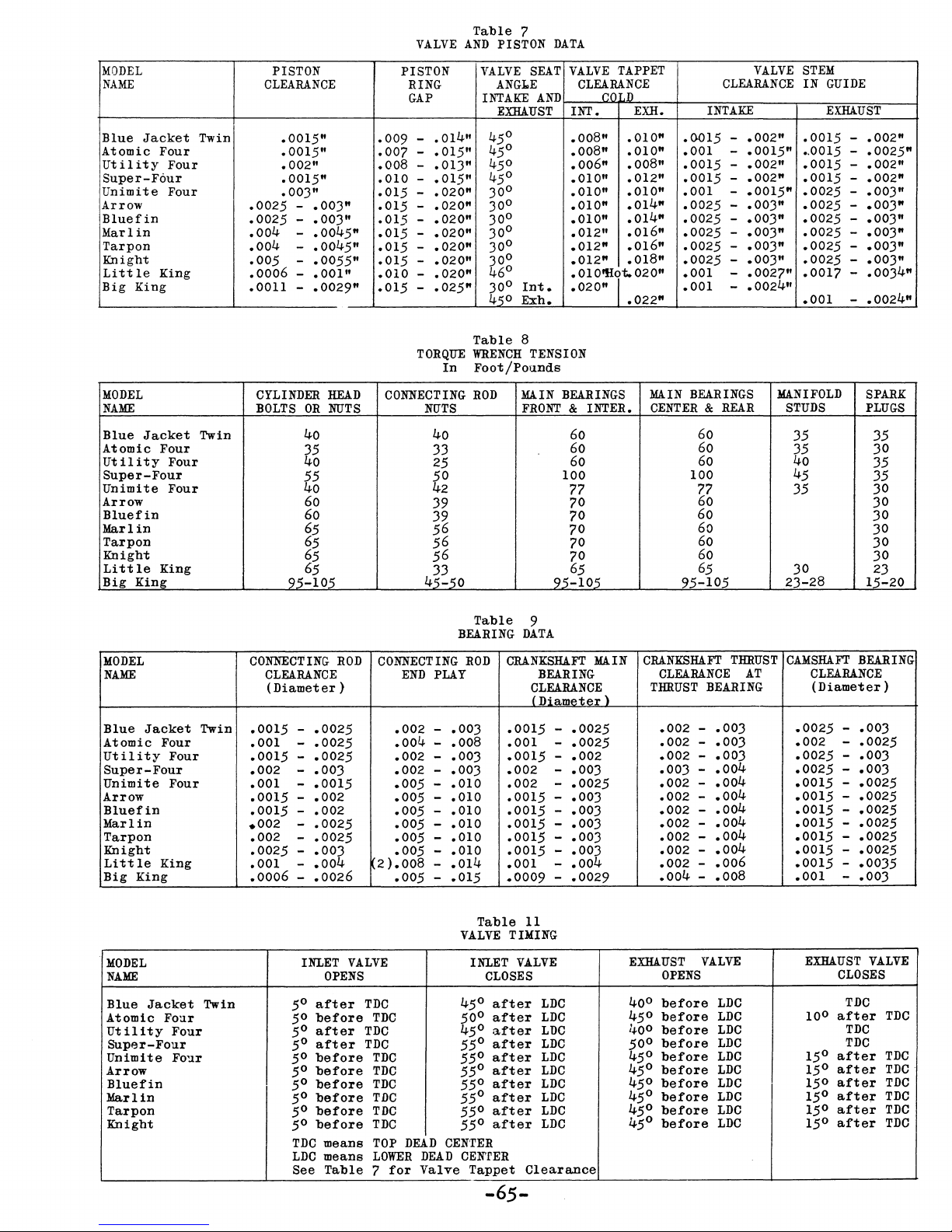
MODEL
NAME
Blue
Jacket
Atomic Four
Utility
Four
Super-Four
Unimite
Four
Arrow
Bluefin
Marlin
Tarpon
Knight
Little
Big
King
King
Twin
PISTON
CLEARANCE
.0015"
.0015"
.002"
.0015"
.003"
.0025 -.003"
.0025 -.003"
.004
.004
.005
.0006 -.001"
.0011 -.0029"
-
-
-
.0045"
.0045"
.0055"
VALVE
PISTON
RING
GAP
-
-
-
-
-
-
-
-
-
-
.014"
.015"
.015"
.020"
.020"
.020"
.020"
.020"
.020"
.025"
.009
.007
.008 -.013"
.010
.015
.015
.015
.015
.015
.015
.010 -.020"
•
015
Table
AND
VALVE
INTAKE
45
45
45
45
30
30
30
30
30
30
46
30
45
7
PISTON
ANGl.E
EXHAUST
0
0
0
0
0
0
0
0
0
0
0
0
0
SEAT
AND
Int
Exh.
DATA
•
VALVE
INT.
.008" .010"
.008"
.006"
.010"
.010"
.010"
.010"
.012"
.012"
.012"
.010'!llt.020"
.020"
TAPPET
CLEARANCE
(!C
I,D
EXH.
.010"
.008"
.012"
.010"
.014"
.014"
.016"
.016"
.018"
.022"
VALVE
CLEARANCE
INTAKE
-
-
-
-
-
-
-
-
-
-
.002"
.0015"
.002"
.002"
.0015"
.003"
.003"
.003"
.0027"
.0024"
.0015
.001
.0015
.0015
.001
.0025
.0025
.0025 -.003"
.0025 -.003"
.0025
.001
.001
STEM
IN
GUIDE
EXHAUST
.0015
•.
0015
.0015
.0015 -.002"
.0025 -.003"
.0025 -.003"
.0025 -.003"
.0025 -.003"
.0025 -.003"
.0025 -.003"
.0017 -.0034"
.001
-
-
-
-
.002"
.0025"
.002"
.0024"
MODEL
NAME
Blue
Jacket
Atomic Four
Ut
ility
Four
Super-Four
Unimi
te
Four
Arrow
Bluefin
Marlin
Tarpon
Knight
Little
Big
King
King
MODEL
NAME
Blue
Jacket
Atomic Four
Utility
Four
Super-Four
Unimite
Four
Arrow
Bluefin
Marlin
Tarpon
Knight
L1
tt
Ie
Big
King
King
Twin
Twin
CYLINDER
BOLTS
OR
40
HEAD
NUTS
a~
55
40
60
60
65
65
65
65
95-105
CONNECTING
CLEARANCE
(Diameter)
-
-
-
-
-
-
-
-
-
-
-
-
.0025
.0025
.0025
.003
.0015
.002
.002
.0025
.0025
.Ooa
.00
.0026
.0015
.001
.0015
.002
.001
.0015
.0015
.002
.002
.0025
.001
.0006
ROD
CONNECTING
2
TORQUE
In
CONNECl'ING
NUTS
40
33
25
50
42
39
39
56
56
56
33
45:"'50
BEARING
END
PLAY
.002
.004
.002
.002
.005
.005
.005
.005
.005
.005
).008
.005
.003
.008 .001
.003
-
-
.003
.010
.010
.010
.010
.010
.010
.014
.015
-
Table
WRENCH
8
TENSION
Foot/Pounds
ROD
MAIN
FRONT & INTER.
Table
9
DATA
CRANK8W.Fl'
ROD
CLEARANCE
iDiamp.tp.r\
.0015
.0015
.002
.002
.0015
.0015 -.003
.0015
.0015
.0015
.001
.0009
BEARINGS
60
60
60
100
77
70
70
70
70
70
65
95-105
BEARING
.0025
-
-
.0025
.002
-
-
.003
-
.0025
.003
.003
.003
.003
-
-
.004
.0029
-
MAIN
MAIN
BEAR
INGS
CENTER & REAR
60
60
60
100
77
60
60
60
60
60
65
95-105
CRANKSH!Fl'
THRUST
CLEARANCE
THRUST
BEARING
.002 -.003
.002 -.003
.002
.003
.002
.002
.002
.002
.002
.002
.002
.004
-
-
-
-
-
-
-
-
-
-
.003
.004
.004
.004
.004
.004
.004
.004
.006
.008
MANIFOLD
AT
STUDS
35 35
35
40
45
35
30
23-28
CAMSH!Fl'
BEARING
CLEARANCE
(Diameter)
-
-
-
-
-
-
-
-
-
-
-
.003
.0025
.003
.003
.0025
.0025
.0025
.0025
.0025
.0035
.003
.0025
.002
.0025
.0025
.0015
.0015
.0015 -.0025
.0015
.0015
.0015
.0015
.001
SPARK
PLUGS
30
35
35
30
30
30
30
30
30
23
15:"20
MODEL
INLET
NAME
50
Blue
Jacket
Atomic Four
Utility
Four
Super-Four
Unimite
Four
Arrow
Bluefin
Marlin
Tarpon
Knight
Twin
50
5°
50
50
50
5°
50
50
50
after
before
after
after
before
before
before
before
before
before
TDC
LDC
See
VALVE
OPENS
TDC
TDC
TDC
TDC
TDC
TDC
TDC
TDC
TDC
l'DC
means
means
TOP
LOWER
Table 7 for
DEAD
DEAD
Valve
Table
VALVE
INLET
CLOSES
0
45
oo
a
50
55°
0
55
55°
55°
55°
55°
55°
CENTER
CENrER
Tappet
-65-
TIMING
after
after
after
after
after
after
after
after
after
after
11
VALVE
LDC
LDC
LDC
LDC
LDC
LDC
LDC
LDC
LDC
LDC
Clearance
EXHAUST
OPENS
0
40
before
before
45°
0
40
before
0
before
50
0
before
45
before
45°
0
before
45
before
45°
before
45°
before
45°
VALVE
LDC
LDC
LDC
LDC
LDC
LDC
LDC
LDC
LDC
LDC
EXHAUST
CLOSES
TDC
0
after
10
TDC
TDC
after
15°
after
15°
after
15°
after
15°
after
15°
after
15°
VALVE
TDC
TDC
TDC
TDC
TDC
TDC
TDC
Page 77

SECTION
INDEX
IX
Page
Aligning
Bearing
Break-in
Carburetor
Cold
Weather -Operation
Cooling
Cooling
Crankshaft
Distributor
Electrical
Engine
Engine
Engine
Identification
Models -General
Rotation
the
Engine
Data
(Table
9)
Maintenance
Sy
stem
Water
System -Installation
Data
Maintenance
System -Installation
Data
of
(Table
of
1)
8
65
34
50
37
41
9
64
45
12
2
3
2
Engine
Stringers
Exhaust
Fifty
Hour
Finishing
Firing
Fuel
Fuel
Fuel
Order
Pump
System -Installation
System -Theory
Generator
Ignition
Installation
Installation
&
Beds -Installation
Piping
-
Installation
Check
Engine
Installation
(Table
5)
Maintenance
of
Maintenance
System -Theory
Data
-
(Table
Preparation
of
2)
for
of
of
7
9
44
12
36
58
11
40
47
38
16
4
-66-
Page 78

INDEX
(Cont.)
Page
Instrument
Introduction
Lubrication
lubrication
Magneto
Major
Oil
Once a
One
One
Periodic
Preliminary
Pre-Operational
Repairs
Pressure
Hundred
Hundred
Panels
Chart
System
Maintenance
Season
Hour
Fifty
Service
Checks -
(Table
Regulator
Check
Check
Hour
-
General
Cbeck
4)
Adjustment
Check
Operation
17
1
35
39
49
64
56
44
44
44
43
33
43
Preparation
Preparation
Propeller
Reduction
Repair
Repolarizing
Reverse
Reverse
Reverse
Reverse
Reverse
Reverse
Parts
Gear
Gear
Gear
Gear
Gear
Gears -Theory
for
Shipment
for
Storage
Shaft
Gears -Theory
-
Installation
Kits
Generator
Adjustment
Adjustment
Adjustment
Operation
Operation
-
- Manual
of
-
Factory
of
Operation
(Fig.
-
Joes
-
Paragon
-
Paragon
Hydraulic
Operation
22)
of
Hydraulic
Manual
1
37
5
42
60
20
54
55
54
36
36
41
Scale
Spark
Drawings -Engines
Plug
Data
(Table
10)
21
58
-67-
Page 79

INDEX
(Cont.)
Spark
Special
Plug
Equipment
Sta-Nu-Tral
Starter
Maintenance
Starting
Starting
Starting
Stopping
Theory
of
Thermostat
Three
Timing
Torque
Thousand
Procedure
Wrench
Maintenance
Manual
-
Electric
-
Fuel
Oil
- Magneto
Engine
Operation
&
By-Pass
Hour
-
Tensions
Gear
Ignition
and
Kerosene
Models
Models
Models
Valve -Installation
Check
Ignition
(Table
8)
of
57
16
56
48
33
34
34
34
38
10
45
46
65
Treatment
Trouble
of
Shooting
Twice a Season
V-Drive
V-Drive
Valve
Valve
Valve
Wire
Wiring
Wiring
Wiring
Wiring
Installation
Unit -Maintenance
and
Piston
Tappet
Timing
Sizes
Diagram -5-unit
Diagram -3-unit
Diagram
Diagram -12
Engine
on
Check
Data
Adjustment
(Table
11)
Electrical
- 60 Ampere
Volt
Arrival
(Table
System
Panel
Panel
Alternator
Generator
7)
(Table
(Fig.
(Fig.
3)
20)
20-A)
(Fig.
(Fig.
21)
21-A)
1
60
44
13
59
65
54
65
17
18
18
19
19
Wiring
Diagram -12
Volt
24 Amp.
Shunt
(Fig.
Generator
22)
-68-
Standard
and
20
Page 80

 Loading...