

Page 1

'
OPERATORS
MARINE
SINGLE
·
8.0
.DIESEL
•
60Hz_.6.0.
-t £ R
"
((,
}
~·
0 . q
litp"''
AND
THREE
II
~
_,.
"'
..,
MANUAL
GENERATORS
PHASE
·50Hz
BJD
.
·
:10.0
11
..
0 • 60Hz_8.·8
.
1·2
..
5 ·
. PUBLICATION
• 60Hz_7.5.•
·50Hz
60Hz_...
~ ~
..
~
-,>,.,,
. 9.4 ·
NO:
36146 l
Rt:V.
~
50Hz
50Hz
5 - JULY 2018
~.-
BtD·
BTD
.
BTO.{Al
~,~~-·TEBBE/fe
-·
. . . .
.Af.W
-··-
.
;j
..
Wf4STERSEKE
MYLES
STANDISH
WEBSITE:
WWW.WESTERBEKE.COM
CORPOIMTfON • 150
INDUSTRIAL
PAIJK • TAUNTON
JOHN
HANCOCK
MA
ROAD
02780
Page 2

..
CALIFORNIA
PROPOSITION
·65
WARNING
Marine
exhaust
are
knovin
to
cause
and
other
Exhaust
colorless
unconsclousnll$$
exposure
•Dizziness
•
•Headache
•
gasses
gas.
can
Nausea
Weakness
and
contain
Carbon
and
Include:
Sleep/nBS$
diesel
and
gasoUn(t
and
some
of
to
the
State
cancer,
birth
reproductive
A
wARNING
Carbon
Monoxide
dealfl~
Symptoms
•
•
•·
•lfllfbility
engine
Its
constituents
of
California
defects,
harm.
Monoxide,
Is
poisonous
of
Throbbing
Muscular
Vomiting
to
an
odorless
and
Carbon.Monoxlde
In
Temples
'fiNitcbing
Think
and
can
cause
Coherently
IF
YOU
OR
ANJ'ONE
(JET
OUT
INTO
seek
medical
until
it
bas
A
WARNING
should
generator.
WESTERBEKE
MONOXIDE
are
Inexpensive
hardware·
DECAL
be
fixed
to a bulkhead
also
DETECTORS
and
store.
ELSE
THE
FRESH
'
attention.
been
inspected
Is
provided
recommends
near
the
easily
obtainable
EXPERIENC~JINY
AIR
IMM.
'EDIA.
Shut
down
and
repaired.
by
WESTERB£KE
near
your
engine
installing
engine
room.
at
OF
TELY.If
tile unit
CARBON
your
and
and
or
They
local
THESE
SYMPTOMS,
symptoms
dq
not
restart
persist,
Page 3
SAFETY
INSTRUCTIONS
INTRODUCTION
Read
this
safety manual carefully.
caused
by failure
precautions.
take
the
necessary
personne4
PREVENT
A.WARIINS:
11/lite
engine
,_,.I.Biflal
•
Do
not
enclosures
•
Shut
off electrical power before accessing electrical
equipment '
•
Use
insulated mats whenever working
equipment
•
Make
sure
(particularly shoes)
•
Remove
electrical equipment.
PREVENT
A
WARNING:
exbaust
system
to
follow
/UUJW
when
dangerous
precautions
and
your
machinery.
ELECTRIC
i$mllllillg,
SHOCK
•
lllltiDul:b
rmttagels
operate
this
machi:nety
and
CO'VetS
your clothing and
when~
wristwatch and
BURNS-
HOT
Dllllllt,.
t:llllfiDIIIIII A fllllllillg
fut«/limental
iw
,_,at
in place;
hot!
• 'Monitor engine antifreeze
coolant recovery tank and periodicaJly at
on the
water
location
when
the engine
I
AwAIIIIIIIII:
• In
case
of
an engme overheat,
before touching the engine. or checldng the coolant·
jacketed
is
COLD.
___
Most
eonditions
to
protect)ourseff,
AC
elllt:ttit:al
whtilt
t:IJii1iel:tl1t
without electrical
skin
are
an
jewehy
ENG.
bOI
engine
coolant
level at the
exhaUst
.,.,_
allOw
accidents
rules
t11ese
t:tHaJt:tltiDsl.
on
electrical
dry,
electrical equipment.
when
parts
fiii!J/De
the
manifold, hilt only
tb.e
erigine
are
and
exist
and
your
t:III8Cfi1Rls
ttJ
$htJte
not
damp
working on
Ill
gets
very
plastic
filler cap
to
cool
PREVENT
• Prevent
sparks
pump,
vapors.
removing
•
Do
Backfire can cause severe injuty or death.
•
Do
the
engine/generator clean
chances of
• Be aware-diesel fuel
·
PREVENT
A
I
_ ill/lilt
• Follow re·fuclmg safety instructions. Keep the vessel's
batches
after fueling. Check below for fumes/vapor before
running
prior
vessel
•
All
when
ventilated
and out
•
Do
• Shut off the fuel service valve at
the fuel system.
spill. DO
sources
servicing.
the fuel system. ·
•
Do
•
Be
• Be certain fuel·line fittings
• Make
BURNS-
flash
to
occur
or other potential sources of spilled fuel or
Use a suitable container
tb.e
not operate
not
smoke
fuel system.
fire.
BURNS-
WAIIIIIIIG:
or
tlealb!
closed
tb.e
blower.
to starting, following the
builder.
fuel
vapors
handling
area
of
tb.e
not fill the fuel tank(s) while the engine is running.
NOf
of
fire
Ensure
not alter or modify the fuel
sure
an
fuel
free ofleaks. ·
sure
a
fire
properly maintained. Be familiar with its
Extinguishers
for
an
applications encountered in this
FIRE
fires.
Do
not smoke or permit
near
tb.e
carburetor,
fuel line, carburetor,
With
the air
cleaner/sUencer
or
permit
flames
Keep
the compartment
and
free
Wipe
up
an
spilled
Will
burn.
EXPLOSION
--.
when
are
highly
and
away
reach
'Thke
allow any smoking,
near
the
proper
supplies
extinguisher
rated
from
fueling.
Run
~g
from
of
ABC by the
Open
the
engine
rec()1TIJ'Tleililatiin
explosive.
fuels. Store fuel in a well-
spark-prQducing
children. ·
care in·catcbing
fuel
system
ventilation
sys•
have a
are
is
:ftam.es
fuel
line,
filter,
to
catch
all fuel
oi:
fuel
filters.
removed.
or
sparks
to
occur
and
the
of
debris to mininri1.e
fuel
and
engine
fuel
vapiiiS.
t:a11
and ventilate cabin
compartment blower
Use extreme care
equipment
the
engine when servicing
any
fuel that might
open
flames,
or
engine
when
exists
when
posi~ve
adequately tightened
installed
NFPA
shutoff
nea.tby
proper
are
appropriate
environment.
or
fuel
fuel
when
near
cause
of the
or
··
serVicing
valve.
and
use.
the
oiL
other
and
is
·
1-w'IWEBTERBEKE
l Engines & Generators
i
•'
.
Page 4

SAFETY
INSTRUCTIONS
ACCIDENTAL
A
WARNING:
or
death!
11
Disconnect the battery cables before servicing the engine/
generator. Remove
it
last.
11
Make certain all personnel are clear of the engine before
starting.
11
Make certain all
re-installed before starting the engine.
BAmRY
A
WARNING:
or
death!
11
Do not smoke
being serviced. Lead acid batteries emit
highly explosive
arcing or by lit tobacco products.
equipment
dming servicing.
11
Never connect the negative
positive ( +) connection terminal of the starter
Do
not test the battery condition by shorting the tenmnals
together.
Ventilate any compartment containing batteries
accumulation
disturb the battery charger connections while the battery
is being charged.
11
Avoid
burns or
wristwatch, rings,
the battery.
11
Always turn the battery charger off before disconnecting
the battery connections. Remove the negative lead
and reconnect
BATTERY
A
WARNING:
severe
11
When servicing the battery
level wear rubber gloves, a rubber apron,
pron;;ction.
destructive.
it off
into
the
caps.
STARTING
Accidental
the
covers,
starting
negative lead first and reconnect
guards,
can
and
hatches are
cause
injury
EXPLOSION
Battery
or
in the vicinity to prevent electrical arcing
Sparks could ignite battery gases or fuel vapors.
of
contacting
sparks that could cause
it
explosion
allow
an open
gas,
which can be ignited
explosive gases.
the
tenninals with tools, etc.,
and any
last when servicing the battery.
can
cause
injury
flame
near the battery
hydrogcm,
by
Shut off all electrical
(-)
battery
cable to the
solenoi~
To
avoid sparks, do not
an
explosion. Remove
other jewelry before handling
electrical
to
ACID
Sulfuric
injury
or
death!
Batteries contain
If
it
at
once with
eyes inadvertently when removing electrolyte
acid
in
batteries
or
checking the electrolyte
sulfuri~
comes in contact
water.
Acid
may
can
cause
and eye
acid
wbic~
With
your skin, wash
splash on the skin or
to
a
prevent
prevent
first
is
TOXIC
11
11
11
11
. A
11
II
11
AVOID
11
EXHAUST
A
WARNING:
Ensure that the exhaust system is adequate to expel
discharged from the engine. Check
regularly for leaks and
water-injected elbow
Be sure the unit and its surroundings are well ventilated.
Run
blowers when running the generator set
Do not
run
equipped with a functioning marine carbon monoxide
detector that complies with ABYC A-24. Consult your
boat builder or dealer for installation of approved
detectors.
For additional information, refer to ABYC 1H-22
(educational information on Carbon Monoxide).
WARNING:
odorless
nausea
gas.
or
death!
Do
not use copper tubing in diesel exhaust systems.
Diesel fumes
systems.
copper tubing resulting in exhaust/water leakage. .
Do
not install exhaust outlet where
through portholes, vents, or
exhaust discharge outlet is near the waterline, water could
enter the exhaust discharge outlet and close or restrict the
flow
of
exhaust:
Although diesel engine
exhaust fumes from gasoline engines, carbon monoxide
gas
is
present in diesel exhaust fumes. Some
symptoms or signs of carbon monoxide inhalation or
poisoning
Vomiting
Dizziness
Headache
Nausea Weakness and sleepiness
MOVING
A
WARNING:
or
death!
Do not service the engine while
situation arises
make operating adjustments,
touching moving parts and hot exhaust system
components.
GASES
Carbon
the generator set or engine unless
Inhalation
can rapidly
Exhaust sulfur causes rapid deterioration
are:
monoxide
make
is
securely attached. ·
carbon
monoxide
produces
destroy
Avoid
overloading the craft.
exhaust
Inability to
Throbbing
. Muscular twitching
(CD)
the
sure
the
(CD)
flu-like
copper
emanst
air
conditioners.
gases
think
in temples
is a deadly
exhaust system
exhaust manifold/
or
engine.
the
is
an
invisible
symptoms,
tubing
in
can be
If
the
are not as toxic
of
the
coherently
PARTS
Rotating
in which it is absolutely necessary to
parts
use
can
cause
it
is running.
extreme care
injury
If
to
boat
a
gas!
ga8es
is
exhaust
of
<kawn
engine
as
avoid
Engines & Generators
ii
Page 5

• Do
not
wear loose clotbing or
equipment;
rings,
moving
• Make sure all
Keep
places
• Do not check
the
engine
•
Stay
when
be
~ught
HAZARDOUS
A
WARNI.
I
.
IIISS!
• ·
Never
• Do not run an
removed.
A
WARNING:
IIIINifally
OPERATORS
Many
of
in
your Operators
notes to highlight critical information.
carefiill.y,
procedures.
avoid
wearing
necklaces
parts. ' ..
protective
at
clear
the engine
or bracelets that
attaching
shields
all
times.
fluid
levels
is operating.
of
the
drive
shaft and the transmission
is
running;
in these rotating parts.
NOISE
NG:
lligb
lltlise
operate
111
phpit:aiJy
an
engine without
engine
with the air intake (silencer)
liD""' wmi'llll
i11capat;/tatBII
MANUAL
the
preceding
maintain
safety tips
Manuai
your
equipment,
jewe]ry
loose
hardware is properly
and
guards
or the
drive
hair and clothing can easily
levels t:all t:allSB
mat:hillett
and
along with
SAFETY
when servicing
jackets~
and
shirts,
could
be caught in
in
their respective
belt's tension
.
itS
nmffler
installed.
..
by
fatigue/
warnings
other
cautions
Read
your
follow all safety
sleeves,
tightened.
hearbig
are~
manual
INSTRUCTIONS
while
coupling
,
atB
and
ABYC,
INSTALUNG
Read
for
tions
ABYC
"Safety Standards
Order
A_BYC
'613
Annapolis.
(410)
www.abycinc.org.
NFPA
''Fire Protection Standard for Motor Craft"
Order
NFPA
lB~Park:
P.O.
·
Quincy,
USCG (United States
"CFR
Code
Order
U.S.
WashingtoJt.
NFPA
the
following
safety
Codes
when
installing your
(American Boat
from;
ThirdDtreet, Suite
MD 21403
990-4460
(National FJie
From:
Box
9101
MA
33
AND
of
Federal
From:
Government Printing Office
AND
.USCG
MARINE
and
()2269.:.9101
CFR46"
Regtilations
D.C. 20404
ENGINES
ABYC,
standards.
and
for Small Craft"
10
Protection
Coast
PUBUCADO.
AID
GENERATORS
NFPA
and
USCG
Follow
UNIVERSAL
Yacht
Guard)
their
engine
Council)
Association)
FOR
publications
recommenda-
ENGINE
Preparations
ough examination
(ABYC)
sources including the USCG
Sections
All
Regulations (FCR).
AND
GENERATOR
to
install
standards.
of
the
ABYC
H-32Ventilati.on
H-33
Diesel
P-1
Instal1atiion
and
Auxilliary
P-4
Marine
E-ll
AC & DC
TA Batteries
installations
must comply with the Federal Code of
an
engine.should begin with a
of
the American Boat and
These
standards
standards of particular interest
for boats
Fuel
Systems
of
Exhaust
Engines
Inboard
Elec1rlcal
and
Battery
Engines
INSTALLAnONS
Yacht
Council's
are
a combination of
and
the NFPA
using
diesel fuel
Systems
and
Systems on Boats
Chargers
for
Propulsion
Transmissions
thor-
are:
j...,.,.IWESTERBEKE
f Engines & Generators
iii
Page 6

When
iilstalling
attention·
WEST.BRBEKE
be
paid
to
the
following
INSTALLATION
engines
information:
and
generators
· ·
it
is
important
that
strict
CODES
· S~
when
AND·-ULATIONS
federal
reguiations,
installing
engines
ABYC
and
SIPHON-BREAK
For
installations
or
-Will
be
break
in
minimum
the
ex1uzust
raw
water damage
If
you
have
to
the
vessel's
rtphon..bretilc.
NO'I'E:
A.
operation.
engine
dimiilge~'
EXHAUST-SYSTEM
The
exhaust'
Exhaust~
and-~
and
toms.
system
MU$'1'·
under
any
where
the~
beloW
die
·v-essers
the
raw
water
supply
of
20''
abo'Ve
the
manifr!ld injection port
to
tk;e
~anti
~y
doubt
about
waterline
· · · · ·
sq,hoti-b~k
Failure_
CiJMiift
under
reqili.rns
tp_properly_
the
...
system's
without
In
tbis
sea
hase
is
recommended..
the
need
~~
a
single
be
designed·to
conditions·
aixl
.
guid8nnes,
generators
manifold/water
waterlirie,
hose
to
the
vessel's
water~
is
pQssibk
the
position
the
~·s
Periofl!.c
mabitain
sijihmi-break
MUS'J;
be
certified
The
use
of
additional
lengtb
prevent
at
-any
the
angle
and
sa.fety
codes
in a
marine
environment.'
inject.Cd
proViSiOnS
exhaust
lit
or
of the
flwJection
a
siphon-break
manufacturer
of
fitting
of
.entry
iniist
~
elbow.
This
Failare to
below
jl.ooding.
water
various
use a Biphon-bretilc
the 'to¢
of
the
..
injected
operating
and
cleaning
can
for
for
marine
use.
this
tYPe
of
hose
and.
clamps to
corrugated~
of
waterlnto the
of
vessels
heel.
ml¥Jt
be
cornpU~
exhaust
maae
waterline
'io
hose
elb9w
is
'llisfiill a
must
be
will
resrilt in
!Joat.
exhaust
conditi~
result
proper
Conugated
allows for
accomplish
hose
elbow
inBtall
to
ensure
p10per
in
catastrophic
riuiintenance.
Marine
eXtreme
these beMs .
can
be
used
exhaust
system
with
close
to
'SipliOii-
looped
when
~ve
a
bends
The
a
AVAILAB~FROM
:aWES'IEM.EKE
SIPHON-BJ:iEAK
LOOP'
WITH
STAiNLESS
A
detailed
engines
to
download
Marlne.lnstallatiiJD
and
Manual
generators,
frail
oar
wibsite
Is
supplied
at
v.ritb
\VViW.westerbeke.com.
IW'IWESTERBEKE
l Engines & Generators
iv
covering
each
gBSQiine
unit A pdf
and
diesel,
is
available
·
Page 7

TABLE
Parts
Identification
Introduction
Diesel
Generator
Preparations
Safety
.........................................................
Fuel,
Engine
Control
for
Shutdown
Starting/Stopping
Generator
Break-In
Maintenance
Cooling
Air
Fuel
Engine
DC
Starter
Engine
Valve
System
Raw Water
Intake Strainer .............................................
Heat Exchanger .......................................... .14
Thermostat ...................................................
Zinc Anode .................................................. 16
Intake
Fuel Filters ...................................................
Fuel Lift Pump .............................................
Silencer
System
.......................................................
Lubricating
Oil Change ................................................... 19
Oil Pressure ................................................. 19
Electrical
Alternator .....................................................
Motor
Testing .................. , ...................................... 22
Disassembly ................................................. 23
Adjustments
Glow Plugs .................................................. 24
Injector ......................................................... 24
Throttle Control/Generator Frequency ........ 25
Drive Belt Adjustment.. ............................... 25
Clearance
11.0 BTD and 12.5 BTD(A) ........................ 26
8.0 and 10.0
............................................
Oil
and
.Panels
Initial
Switches
Procedure
Procedure
Schedule
Engine
....................................
Start-Up
and
...............................
......................................
Coolant.
.........................
Sensors
.............
.........................
..................................................
Pumps .......................................
............................................
Oil
.......................................
System
.........................................
.....................................................
...........................................
and
Timing
BTD
........................................ 27
.............................
OF
CONTENTS
.2
3
......
5 10.0 Kw
6 11.0 Kw
7 12.5 Kw BTD(A) ......................................... 34
8
9
.1
o
11
13
14
14
15
16
17
17
18
19
20
20
22
24
26
Specifications
8.0 Kw
BT
Generator 6 and
Voltage Regulator ........................................ 38
BT
Troubleshooting Chart ........................... 38
Internal
Resistance Values ........................................ 39
Generator
No
Load .......................................................
Full Load .....................................................
Generator Frequency ..................................
6 Stud
Internal
Resistance Values ....................................... .42
Internal
3
Phase,
AC
Voltage
Shore
w ..
Power
o·
1nng
#34651 - 8
#36412#36412#36412
#36412
#41479-
#41479
#43853#43853
#43944#43944
Remote
Power
Lay-Up
Take
and
Suggested
.......................................................
BTD
................................................ 28
BTD
.............................................. 30
BTD
.............................................. 32
12
Stud
..............................
Wiring
Wiring
Wiring
sagrams
Oil
Schematic
Voltage
AC
Adjustment
Connections ..............................
Schematic
(12
Stud)
...............
........................
(&Stud)
.................
Diagram
12
Wire,
Connections
Reconnectable
Transfer
Switch
...................
BE 3 Phase
................
...........................
...................................................
BT
.............................................
No Relays ..................................... 47
Schematic No Relays ................... 48
-Two
- Schematic Two Relays ................. 50
- Schematic .....................................
-Schematic
-
Fill
Recommissioning
Spare
Relays .................................. .49
BTD
and BTD(A) .......................
BTD and BTDA ........................... 53
..................................... 54
BTDA Diagram ............................ 55
BTDA
Schematic ......................... 56
...................................................
Off
System
.....................................
...........................
Parts
......................................
.
37
.39
.40
40
40
.41
.41
.42
.43
44
.45
.
46
.51
52
57
58
59
61
Engines & Generators
1
Page 8

·
PARTS
IDE.NTIFIC.ATIO
N.
/ALL
MODELS
The Control Panel faces aft on some of these models
_with the .emergency Stop
Swi~ch
on the back .
CONTRO
L
PANEL
.
OIL Fi
ll
AC
CONNECTION
OUTLET
DRIVE
BEl
COVER
REA
R
THERMOSTA
Ti
ASSEMBLY
RAW
WATER
PUMP
FRONT
RIGHT
SIDE
MANIFOLD
PRESSURE
CAP
COOLANT
FILL
,_
,-~ _
OIL
SUMP
2
AIR
INTAKE
SILENCER
-
DC
ALTERNAT
OR
FUEL-RUN
SOLENOID
OIL
PRESSURE
SWITCH
OIL
DRAIN
HOSE
FRONT
GENERATOR
EMERGENCY
STOP
SWITCH
ART
SOLENOID
Page 9

This
WESTERBEKE
WESTERBEKE's
technology.
dependable
Thank
In
order
is
important
manual
manual
throughout.
your
This
is
an
Manual
ordered
Dealer
We
performance
you
for
to
get
that
is
designed
carefully
Should
nearest
WESTERBEK;E
is
your
operators
Installation
is
available
in
book
WARRANTY
Your
WESTERBEKE
product
documentation
Registration
Corporation
register
Customer
registering.
your
date
Customer
Card
or
your
products
Identification
If
'you
product
available.
model
Identification
Diesel
Generator
long
years
of
take
great
pride
of our
engines
selecting
the
WESTERBEKE.
full
use
and
benefit from your
you
operate
and
to
help
you
do
and
observe
your
Manual
in
fonn
from a WESTERBEKEIUNIVERSAL
generator
manual.
and
Parts
pdf form
all
dealer for
Along
on
is
experience
in
the
superior durability
and
maintain
this.
Please~
the
safety
require
assistance.
wi~
Information. A Serv1ce
our
website
PROCEDURES
go
Warranty
you
can
to
our
warranty
do
not,
number,
package.
card
Statement
There is a
fill
out
and
mail
website:~.westerbeke.com
on
line.
You
in
the
mail
within
please
contact
the
serial
number
Card
I.....,.IWESTERSEKE
J Engines & Generators
Customer
MR.
MAIN
HOMETOWN,
Model
Expires
NOTES,
As
maintenance
engine,
CAUTIONS,
NOTE:
A
observed,
your
Identification
GENERATOR
STREET
______
USA
_____
CAUTIONS
this
manual
An
takes
schedules,
critical.infonnation
and
operating
CAUTION:
can
result
engine.
OWNER
_
_
AND
WARNIN~S
you
through
and
troubleshooting
will
WARNINGS.
procedure
Procedures,
In
the
essential
damage
Serial#
the
operating
be
highlighted
An
explanation
which
or
____
to
if
not strictly
destruction
INTRODUCTION
a product of
and
advanced
generators.
generator
it
correctly.
re8.d
this
precautions
servicing,
this
is
included
Warranty
to
should
factory
and
of
note.
contact
manual,
or
can
Westerbeke
rece1ve
60
days
and
in
service
procedures,
your
marine
by
NOTES,
follows:
of
This
.there
be
in
~d
of
have
_
and
the
·
it
.
a
PRODUCT
Pioduct
brochures
WESTERBEKE
WESTERBEKE
CONTENT
WARRANTIES
THEREJ'O,
COMPLETENESS
BE
UABLE
iNCURRED
.
OF
THE
WESTERBEKE
time
software
WESTERBEKE
provided
WESTERl3EKE
be
relied
the
respective
but
is
WESTER.BEKE
to
determine
product
SOFTWARE
software,
FURNISHING
span
between
and
with
upon·
imperative
software being consulted
(tech
and
catalogs),
are not
CANNOT
OF
SUCH
OR
REPRESENTATIONS
INCLUDING
THEREOF
FOR
ANY
IN
CONNECTION
customers
printings of
the
l.inavoidable
manuals.
WESTERBEKE
or other suppliers,
exclusfvely
product.
the
It
that appropriate
or
the
accuracy
data,
provided
within
SOFIWARE,
TYPE
OR
not qnly
supplier
paltS,
lists,
manuals,
from
sources
WESTERBEKE's
BE
RESPONSIBLE
MAKES
WITH
ACCURACY;
AND
OF
USE
should
WESTERBEKE
existence
In
summation,
products, whether
as
the
and currentness of
TIMEliNESS
WIU
IN
DAMAGE
WITH
OR
ARISING
OF
SUCH
also
keep
of
earlier
product
must
not
definitive
makes
representatives
in
questi,on
by
good
the
customer.
authority
other
than
control.
FOR
THE
NO
RESPECI'
NO
EVENT
OR
INJURY
OUT
SOFIWARE.
in
mind
the
product
·
software
from
and
cannot
on
sense
of .
be
consulted
the
. ·
OR
.
PROTECTING.Y~UR.INVESTMENT
Care
at
'f:4e
factory
during assembly and
have
resiuted
maiJy
manufiicturer
install~·
operaftd
buyer/owner.:.Operator.
NOTE:
•
Proper
• An efficient
ananf:t.siphon
engine.
w
Changing
mainte~UZ'nce
•
Proper
n.eitts
manuaL
a
Use
•·
Wmterize
Recommis~rtin~'
in a WESTERBEKE
thousands of hours of dependable
cannot
control how or where the
in the vessel
'and
serviced
SiX
imp~'(tant
engine
or
in
steps
and
generator
·
the mannerin
the
well-designt!fd
breafc
to prevent waterfrom
· .
the
engine oil and
sclledule.
maintettillibe
i:Zecording
to
of
the
· · ·
cledli;:filter{!d
your engine
#2 dieaelfnet.
ticcoramg
section
field.
to
ensure
ex1uiust
oil
all
engine and
m.ai:tttenance
in
~orough
generat9r
This
long
instDllaiion
capable
~ervice;
which
is
up
to
generator
and.
systt!fm
fi1ters1
(lCcording
generator
schedule
to
the
~'LD.y·tzp
this
manual.
testing
However
generator
the
unit
the
life:
alignment.
that
includes
entering
in
this
atul
of
the
is
is
the
..
io
tlie
colf!.PO•
A
WARNING:
followed,
can
result
Procedures,
in
personal
which
injury
if
not
or
loss
properly
of
life.
Engines & Generators
3
Page 10

INTRODUCTION
SERIAL
The
nameplate
a
eJiliaust
The
the
the
~tion
NUMBER
engine's
engine's serial number
engine
side
below
model
mounted
manifold.
block
oil
flU
opening. Take time
on
the
LOCATION
and
serial number are lqcated. on
on
the side ofthe water jacketed
is
also found stamped
on
a flat surface just above the
to
enter this infonn-
illustrated nameplate.
in
NOTE:
A
carbon
monoxide
by
WESTSRBEKE.
engine
room.
UNDERSTANDING
The
diesel
engine closely resembles
since
the
mechanism
are
arranged
the
same
diesel
cbnnecting
Therefore,
same
most important factors
maintenance
Replacement
time
periods
contanlination (that is,
system
of
the
designed
The diesel engine does differ fromthe gasoline
however,
carburetor
their
place
which
above a closed
general
type
engine
has
the
rods
and lubricating
to
a great extent, a diesel engine
preventive
is
same
performs
maintenance
of
the
of fuel and lubricating
specifi~d
also
essential.
brand
of
specifically
in
its
methodof.han.~g
and
ignition systems
is
a single component-
the
warning
Affix
this
decal
THE
DIESEL
is
essentially the same
crankcase; the crankshaft
as
that of a gasoline
same
types
of valves,
system.
as
a gasoline
are
proper ventilation
fuel,
·lubricating
is a
must,
and frequent
water,
sediment, etc.) in
Another important
high
detergent
for
diesel
engines.
ttre
function of
both.
decal
has
in a visible
ENGINE
the
gasoline
..
The
engine;
camshaft,
requires
engine.
and
arid
cooling
filter
elements at
factor
diesel
lubrication
and
firing
done
away
the
fuel
injection
been
provided
position
engine,
cylinders
and
the
The
proper
systems.
checking
the
fuel
is
the
engine,
of
fuel.
with
and
pump
in
the
is
of
the
pistons,
the
for
use
oil
The
in
-
An
identification
displays
CARBON
WES1ERBEKE
detector
even
The
from
elbow/exhaust
entering
If
air
the
engine
MONOXIDE
in
the
vessels
in small amounts,
presence
the
carbon
and
engine·
your
monoxide
correct
of
hose,
boat.
the
plate
on
the
model
and
DETECTOR
recommends
living
is
carbon
monoxide
or
generator
or
the
is
present,
problem
top
of the engine
serial
number.
mounting
quarters.
deadly.
or
fumes
immediately!
Carbon
indicates
from
the
from
.
ventilate the
a carbon
an
exhaust
a nearby
area
air
intake
also
monoxide
mono:xide,
exhaust leak
vessel
are
with
clean
ORDERING
Whenever
provide
and
generator serial number
black
provide
your
description
separately furnished Parts
WESTERBEKE
parts
original
SPARES
Certain spares
WESTERBEKE
dealer
See
the
Generator
INSTALLATION
The
Westerbeke
supplied
PARTS
replacement/service parts
the
generator
name
plate located
us
with
generator set.
and
are
frequently
equipment.
AND
will
assist you in preparing
SPARE
Accessories,
. . .
model
this
information so
In
addition,
part number for each part
packaged parts because will
not made
ACCESSORIES
will
be
needed
generator.
PARTS
page in this
MANUAL
Installation
with
this
unit.
see the
number,
as
they
appear on
on
the generator
we
include a complete
List).
Also insist
to
the
same
to
support
Your
local WES'IERBEKE
an
manual.
ACCESSORIES
Manual
are
needed,
engine serial
rnay
and
inventory of spare
publication
always
number,
the
silver
end.
You
must
properly
part
needed
(see
upon
fit
or
generic
specifications
maintain
For
Engine
brochure.
#043268
GENERATOR
10
and
identify
the
as
your
parts.
and
is
DECAL
Engines&. Generators
4
Page 11

DIESEL
FUEL,
ENGINE
OIL
AND
ENGINE
COOLANT
DIESEL
Use a diesel
SAE J 313
dies~!
Care
Use
in
dirt
secondary
is
fuel
improper
the
following
Purchase a well-known
combat
mended
'Klee~1
diesel
Install
fiHeriwater
The
such
ENGINE
Use a good brand of engine oil, with
and
manual. Change the engine oil and oil
hours of engine break-in operation and
of
Westerbeke Corporation does not
the use of synthetic
break-in
change intervals must
SCHEDULE
if
NOTE:
statements regarding synthetic
FUEL
fuel
that
meets
the
requirements
and
fuel
Of
The
only
clean
your
engines
particles
important
can
be
storage
tank
for
practice
BACTERIAL
such
+
Cetane
fuel
and
Raycor
filters. A 10
has a Cetane
according
Fuel
diesel
fuel
which
filters
can
to
buy
rendered
facilities.
your
engine's
as
Bio-Bor
Boost
when
an
regularly
separator
500
MA
micron
injection
might
clean
is
Ultra
service a good,
rating of
to
ASTM
0975.
Supply
fuel!
The
clearance
pump
pass
through
damage
unsatisfactory
advisable:
between
or
fuel,
To
daily
brand
growth
and
to
help
Low
230
filter
these
and
assure
use
of
fuel.
on
an
additive
restore
Sulfur
the
RMAM
element
the
OIL
SAE
as
stated in the
operation thereafter.
must be performed using conventional
section
synthetic oil is
The
infonnation above supersedes all previous
SPECIFICATIONS
oil.
If
synthetic oil
be
as
of
this manual and not
used.
listed
oil.
#45
is
finely
keep
by
that
is
clean
The
fuel
diesel
visual-type
fuel
are
approve
in
of
No.
2-D
or
higher
grade
of
the
components
very
critical;
invisible
the
primary
machined
it
clean.
careless
the
use
tank
such
lubricity
tank
and
.good
is
recommended.
an
API
filter
then
is
used,
the
MAINTENANCE
and
parts.
The
best
handling
fuel
going
and
pure,
the
of
additives
is
recqm-
as
Diesel
back
intO
is
being
used.
fuel
the
engine.
examples
classification
section of this
after the initial 50
every
100
or
disapprove of
engine
oil.
Oil
to
be extended
of
It
or
into
to
the
of
hours
ENGINE
WESTERBEKE
and
chemicals
The
run
engine
circuit
antifreeze
(SCAs)
to
The
being
NOTE:
antifreeze
PURCHASING
Select a brand
Antifreeze
additive
cylinder
brands.
engines.
mixture
needed.
MAINTENANCE
COOLANT
50%
distilled
that
antifreeze
at
proper
to
the
from
that
that
long
term
distilled
poured
Look
that
speci11~d
to
protect
walls.
that
offer
Select
will
Change
recommends a mixture
water.
Distilled
can
corrode
performs
temperatures
coolant,
rust
contains
keep
protection.
water
into
for
the
is
double
and
and
corrosion.
Supplemental
the
antifreeze
and
antifreeze
the
cooling
new
environmentally-friendly
1ww
available.
ANTIFREEZE
of
antifreeze
for
diesel
against
Prestone
the
always
·and
antifreeze
pre-mixed
be
added
the
antifreeze
SCHEDULE
MAINTENANCE
Change
number
protect
COOLANT
TI1e
contraction
without
provided
water
operating
the
engine
of
operating
and
lubricate
RECOVERY
coolant
recovery
of
the
introducing
with
fresh
coolant
conversion
the
engine.
coolant
hours
the
allows
engines
air
into
water
engine
kit
water
internal
duty.
by
transferring
lubricates
Look
chemically
should
circuit.
specified
engines
cavitation
Zerex
specifically
variety
to
the
mixture
in
every
five
as
the
chemical
have a limited
TANK
for
the
coolant
the
system.
cooled
models
and
must
of
50%
is
free
engine
surfaces.
It
allows
heat
and
protects
for a good
Cooling
balanced,
be
premixed
for
diesel
contains a special
erosion
'of
are
two
nationally
for
use
in
so that
the
cooling
system
according
this
manual.
years
regardless
additives
expansion
during
engine
This·recovery
and
with
be
installed
antifreeze
from
the
the
engine
away
from
the
cooling
quality
Additives
crucial
before
long
lasting
engines.
the
engine's
known
(fiesel
cO!TeC:t
when
to
the
of
that
life.
and
operation
tank
the
fresh
before
to
the
'
the
is
NOTE:
T7lis
located
at
can
be
located
particular
Engines & Generators
5
tank,
with
or
above
the
below
installation
its
sh01t
level
the
level
makes
of
this
run
the
of
of
plastic
engine's
the
engine's
necessary.
hose,
is
manifold,
manifold
best
but
if
it
the
Page 12

GENERATOR
CONTROL
PANELS
DESCRIPTION
Thls
manually
diesel
generators
engine
control
All
three
following
PREHEAT:
preheating
bypassing
turns
on
the
excitation.
When
the
·panel
lights,
activate.
START:
The
energizes
While
the
START
switch
begins
to
PREHEAt
pressure
reaches 5 -
STOPPING:
switch a
switches to the
nates this
engine.
To
stop the engine, simply depress the STOPswitch. The
DC
path
the
relay
should be held depressed until
completely.
NOTE:
When
gauge
and
last
temperature
will
retwn
OF
SWITCHES
controlled
is
panel
switches are momentary contact type
functions:
TI1e
PREHEAT
the
engine
the
engine
fuel
solenoid
PREHEAT
gauges
START
the
starter solenoid and activates the starter
PREHEAT
engages·
fire,
the
switch
The STOP toggle switch is a nonnally closed
DC
path through the three automatic shutdown
K2
DC
path to the
to
the
K2
and
the engine shuts
the
engine
the
oil
and oil press
to
zero
,series
of WES1ERBEKE marine
equipped with toggle switches
and,
optionally, at remote
toggle switch serves two purposes:
for
easy starting and defeating of
oil
pressure switch. The defeat function
..
instrument power
switch
is
depressed,
and
meters
and
fuel solenoid
toggle switch closes the
switch
is
still depressed, depressing
the start solenoid. When.the engine
START
pressure
switch should be released. The .
should
not
be released until
10
psi.
run relay. Opening this switch termi-
K2
run relay shutting
run relay is terminated, de-energizing
down.
The STOP switch
the
generator shuts
is
shut
down,
the water temperature
gauge will continue
we
readings displayed.
once
electrical power
and
the
Kl
is
restored.
panels.
and
alternator
voltmeter,
will
relay that
the
down
to
on
the
serve
..
oil
the
down
register
They
the
the
the
EMERGENCY
stop switch
is
normally closed.
will
open the
panel and shut the engine down.
switch is not toggled
petforming maintenance.
DESCRIPTION
Coolant
Engine coolant (water) temperature should normally
175°
to
Engine
Oil pressure (psi)
load but should
DC
Voltmeter
Indicates the amount
13.5V
STOP:
on
the
DC
circuit
OF
Temperature
195° F (80°
Oil
Pressure
may
range between between 30
to
14.4V.
The EMERGENCY.
side of
the
control
box.
When
depressed, it
to
the
control
As
~he
it
can
be
used
when
GAUGES
to
90°
C).
fluctuate depending
the
battery is being charged should
.
on
to
the
60
psi.
Hourmeter
Registers elapsed time and is used
petform scheduled maintenance.
REMOTE
For remote operation of
switches are
connected
serve the same functions
switch
serves
WIRING
PANEL
used.
The PREHEAT
in
parallel
is
in
series with
the
same function. There
DIAGRAM
with
in
the
the gauge panel's switches
as
the
this
as
a guide for
generator system,
and
START
in
the
gauge panel.
gauge panel's STOP switch
is
a REMOTE
manual.
when
the
same
switches
The
START/STOP
GENERATOR
:J%
~l~
RELEASE
STARTER
::
PREHEAT
•
MUST
PRESS.
1ST.
-
tO
e
·wESTERBEKE.
NOTE:
For
additional information
STARTING/STOPPING PROCEDURE, DC
DIAGRAMS and TROUBLESHOOTING
ty
.
STOP
START
~').
(
,f~~
on
Control
PRESS
2ND
,
.....
,:
Panels.
WIRING
GAUGES.
indicate
generator
show
to
three
are
and
STOP
and
Refer
to:
£Engines
6
& Generators
Page 13

PREPARATIONS
FOR
INITIAL
START-UP
PRESTART
This section of
ration,initial starting, break-in, starting
stopping procedures.
the
conditions indicated
will
set
Before starting your generator set
prolonged layoff, check
0 Check the engine
at
0 Check the
tor bowls·for contaminants.
INSPECTION
the
manual
provides the operator
Follow
and
your
give reliable performance
the
following
oil
level.
the high mark
on
the dipstick.
fuel
supply and examine
(warm
the procedures
WESTERBEKE
and
long
for
the
first
items:
Add oil
to
the
0 Check the DC electrical system. Inspect
and
battery cable connections. Make certain the(+)
tery cable is connected
negative (-) cable is connected
the
coolant
the
manifold.
is
(this location
0 Check
and
at
0 Visually examine
parts, disconnected
threaded connections.
0 Check load
the
wiring diagrams.
leads
0 Examine air inlet
0 Be sure
to
0
Be
the
system requires,
connected
3-phase systems
ply
loads.
no
other generator or utility power
load lines.
sure that
neutral is properly grounded (or
the
in
power systems
to
the
wrong
line-to"neutral voltage
0 Make sure the mounting installation
0 Make sure that
the
to.
the starter
tagged).
level
in
both
the
unit.
Look
wires,
unattached
for
correct connection
and
outlet
and
that the generator
load neutral.
an
incomplete or
generator
solenoid
to
the
the
plastic
for
loose or
for
air
flow
with a neutral
ungrounded)
In
single
open
on
is
is
properly
hoses,
with
or
cold)
as
presented
service
time
maintain
fuel
filter/separa-
wire
connections
and-the
engine
ground
recovery
missing
and
as
specified
obstructions.
is
connected
line
neutral
phase
and
neutral
unbalanced
secure.
grounded.
prepa-
and
for
generator
life.
or
after a
the
level
bat-
stud
tank
check
in
that
as
the
is
properly
some
can
sup-
A
CAUTION:
recommended
be
switched
and,
in
cold
will
prevent
of
the
AC
When
that
all
OFF
until
climates,
damage
machinery
starting
AC
loads,
the
engine
starts
caused
and
will
the
generator,
especially
has
come
to
warm
up.
by
unanticipated
prevent a cold
stalling.
GENERATOR
The speed
however, it is advisable to verify.
60 hertz The engine no-load speed is set
50
hertz The engine no-load speed is set at
The speed of the generator engine
however
adjusted
·VOLTAGE
actual service load or test load
the load
adjusted to suitable
your authorized WESTERBEKE service
VOLTAGE
of
the generator engine is adjusted at the factory,
At rated amperage hertz output may decrease
58.5-
59.0 Hz.
At rated amperage hertz output may decrease
48.5 - 49.0 Hz.
is
adjusted
it
is
advisable
to
optimum
ADJUSTMENT
to
be
used
to
values
in
service.
values
verify.
The voltages
no-load and full-load (refer
in
this manual). If possible,
of
the same power factor
If
the
voltage cannot
and
a fault seems evident,
dealer.
it
large
up
to
This
precaution
operation
engine
at
61.5 - 62
51.5
at
the
are
is
motors,
speed
from
Hz.
to
Hz.
to
factory,
easily
to
apply
as
be
contact
RECAP
DIPSTICK~
GLOW
PLU
CONNECTION
SIDE
Engines & Generators
7
OIL
FILL
CAP
OIL
FILL
CAP
Page 14

SAFETY
SHUTDOWN
SWITCHES
AND
SENSORS
SAFETY
The engine is protected
switches. Should shutdown
without
SHUTDOWN
finding and
correcting
SWITCHES
by
three automatic shutdown
occur,
do
not attempt
the
cause.
Refer
to
to
restart
the
heading "Engine Stops" in the TROUBLESHOOTING
section
The following
switches:
High
An exhaust temperature switchis located on
injected exhaust
The switch's contact open at 260°
The switch's contacts:elose when the temperature lowersto
of
this
manual.
is
a description
Exhaust
If
the
contacts open
DCruncircuitisinterrupted and
approximately
Temperature
elbow.
due
225°F (l07°C).
EXHAU$1
TEMPERAfURE
(HIGH)
of
Its
contacts are normally closed.
to
a high coolant temperature, the
SWITCH
these automatic shutdown
Switch
the
water
the
unit shuts
"270°F(l27°
down.
-127°C).
Low
Oil
Pressure
A
low
oil
pressure switch
gallery adjacent
open when
monitors the engine's oil pressure. Oil pressure closes
contacts. Should the engine's
contacts open interrupting the
down.
the
Switch
is
located off the engine's
to
the oil
filter.
Its contacts
engine is in a static state, this switch's sensor
oil
pressure
DC
run circuit shutting the unit
OIL
PRESSURE
SENDOR
are
fall
to
normally
5-l 0 psi, the
oil
the
Engine
A high engine coolant temperature switch located
thermostat housing.
contacts open
circuit
contact
contacts close when the coolant
195°F (107°C).
Coolant
due
is
interrupted and
open
at
approximately 210°F (99°C). The switch's
Temperature
Its
contacts
to
a high coolant temperature,
the
SWitch
are
norma1ly
unit shuts down.
tem.perature.lowers
closed.
The
THERMOSTAT
ASSEMBLY
on
the
If
the
DC
switch's
to
the
run
Engine
The engine's DC circuitis protected
230 amp DC breaker. Should amperage in excess of 20 amps
by
engine's
Investigate
This
The·
shown
DC
Circuit
draw
through the breaker caused by an issue
DC
circuit, it will open and shut
the
is·
done by pushing the red
wiring
connections
in
the
WIRING
Breaker
issue and then manually reset
b1.1tton
ENGINE
DC
BREAKER
CIRCUIT
to
·these
components
DIAGRAMS
in
b}'~'l
engine mounted
the
in.
.
this
manual.
with
the
unit down.
the
breaker.
are
/"W'JWESTERBEICE
. · E'ngfnes & Generators
' 8
Page 15

STARTING/STOPPING
PROCEDURE
THE
STARTING
Westerbeke
glow
plugs
illustration
der.
The
glow
that
its
tip
glow
plug
glows
red at the
is
a rapid start
This
system
circuitry
depressed
while
button
NOTE:
HEAT
activates
HEAT
START:
the
Upon
release
5 -
low
will
is
keeping
is
depressed
The
switch
the
intermittently
GLOW
While
START
engine
the
10
psi.
oil
pressure
remain
SYSTEM
diesel
generators use electric starters assisted
for
both
below
shows
plug
is
in
the
injector nozzle's
is
energized
tip
with
is
common
designed
for
the
time
the
PREHEAT
START
switch
is
depressed.
glow
plugs
still depressing
switch.
starting,
PREHEAT
Then
as
protective
energized
normal
and cold weather starting. The
a cross-sectional
is
located
in
the
by
the
PREHEAT
and
assists
in
igniting
less
wear
on
the
to
WESTERBEKE diesels.
so
that
the
PREHEAT
specified
to
crank
in
button engaged,
the
engine.
will not
energize
Depressing
in
the
cylinder
to
avoid
overheating
the
PREHEAT
This
will
engage
release the
switch until the oil pressure reaches
long
as
and
START
the
high water temperature
circuits
continue
view
of
combustion chamber
spray
path.
When
button,
the
the
fuel.
starter.
button
the
preheat
the
do
not
to
run.
NOTE:
A
voltage
when
is
depressed.
unless
the
PREHEAT
head
so
the
glow
switch, depress
starter
switch.
activate,
When
drop
the
preheat
chart.
the
the
use
solenoid.
Do
starting:
will
by
one
cylin-
so
the
plug
The
result
The
start
must
be
Then,
START
PRE-
switch
the
PRE-
plugs.
not
and
the
engine
occur
~witch
Failure
Should
depressed
wait
longer.
'A
engine
filling
pump
lng
engine's
the
closing
draining
of
lng
to
Start
the engine
for
10
30
seconds;
Never
run the
CAUTION:
starting
with
raw
Is
pumping
system
during
cylinders
exhaust
the
from
system
the
raw
the
exhaust
e,x~esslvsengine
raw
water
owner/operator
Remote
The
start
gauges.
lights
rpm.
since
A.
B.
Starting
remote
start
panel
except
When
when
the
This
indicates
the
starting of
When
the
start/stop
START
engine
the
START
depressed
up
the
green
engine
After
released,
PREHEAT
supplies
switch is depressed
this
LED
light
switch.
which
series
LED
is
running.
the
generator
the
voltage
starting
PREHEAT
panel
LED
for a few
closes
path
will
switch
not
start
when
to
20
seconds,
repeat
the
procedure
starter
for
Prolonged
can
water.
raw
cranking.
by
water
result
This
water
way
fills.
Prevsnt
supply
cranking
In
may
through
This
of
muff/sr,
cranking.
entry
Is
not a warrantable
should
keep
this
Procedure
panel
is
the
same
that
it
has a green
at a remote
generator is
when
the
the
will
Continue
for
remain
generator's starter
generator
LED
light
brighten
seconds
the
oil
i2V
is
is
operated
to
the
running
the
START
switch
light
will
dim.
to
pressure
B+
brightly
started
START
the
START
release both
above
more
than
Intervals
the
engine
exhaust
happen
the
because
the
raw
raw
water
exhaust
this
from
manifold
through-hull
and
correcting
Engine
in
mind.
as
the
engine-mounted
LEP
light
location,
may
is
depressed
will
and
When
signaling
hold
to
allow
to
the
and
will
first
switch.
the
at
approximately
switch
not
be
illuminate.
the
starter
the
to
release
the
PREHEAT
oil
safety
switch
fuel
run
illuminated
the
START
not
crank
because
switch
is
switches
and
30
and
preheat
seconds.
without
system
the
water
cool·
can
enter
once
happening
shut-off,
the
cause
damage
result·
issue;
and
no
green
LED
600
can
be
released
audible.
at
the
remote
When
cranks
the
engine
starts
the
pressure
that
solenoid.
while
switch
unless
this
switch
to
is
the
the
the
by
the
the
build
in
The
is
the
Once
the
engine starts, check
proper
oil
pressure
light'load
temperature
applying
NOTE:
to
heavy
Some
Depressing
will
help
stabilize
temperature
the
engine.
the
generator
to
come
loads.
unstable
the
PREHEAT
reaches
and
the
up
running
engine
140-
the
engine's
battery charging
and
allow
the
to
140-150°
switch
may
rpm
occur
for
until
(60-66°
10-15
150° F and a load
the
instruments
voltage.
engine's
C) before·
in a cold
second
operating
is
applied
for
Apply
a
operating
engine.
intervals
STOPPING
1.
·
2.
3.
Remote·Stopping.
To
stop
to
Engine., & Generators
the
-circuit.
generator
goes
9
Remove
allow
the
stabilize
Depress
is
coinpletely
Now
release
PROCEDURE
the
AC
electrical load
generator·to run
its
operating temperatures.
the
STOP
stopped.
the
STOP switch.
switch
.
and
Procedure
the
generator, depress the STOP switch
normally
out.
The
closed
B+
STOP
switch must
comes
to a complete stop
path for voltage
for
be
from
three
to
hold it
to
hel'd
open until the
and
the green
the
generator
five
minutes
until
the generator
which
the engine's run.
LED
and
to
opens
light
Page 16

GENERATOR
BREAK·IN
PROCEDURE
DESCRIPTION
Although
hour
assembly
operated
life
ated
Breaking-in a new
piston
and
scored,
the
Your
conditioning
to
Perform
following:
Start
section.
water
AFTER
Once
tion
between
A
generator
your
of test
operations
procedures
properly, a break-in
of
your
engine
and
serviced
rings
to
smoky
operation
which
break-in
maximize
new
this
the
engine
Run
pump,
period.
engine
operation
the
conditioning
the
oil
START-UP
the
generator
and
then
encourage
20%
and
CAUTION:
by
engine
is
during
engine
the
cylinder
is
caused
requires
performance
according
engine
pressure,
has
60%
Do
running
has
experienced a minbnum
at
the
factory
to
were
followed
dependent
its
initial
basically
walls.
indicate
by
overloading
approximately
to
break
carefully,
to
while
battery
been
a fast
of
full-load
not
attempt
time
is
upon
hours
Excessive
that
the
in
each
and
service
the
STARTING
checking
charging)
started,
warm-up.
for
to
and
required.
how
involves
cylinder
keeping
check
the
break-in
without a load.
make
sure
that
the
The
the
engine
of
use.
seating
oil
consumption
walls
the
generator
50
hours
moving
that
part
life
of
the
in
mind
PROCEDURE
all
systems
are
functioning.
for
proper
Run
the
first
10
your
of
one
accurate
engine
service
is
the
are
during
of
initial
in
order
engine.
the
(raw
opera-
generator
hours.
oper-
CHECK
0
0
0
0
To
the
cuit
NOTE:
draw
draw
GENERATOR
GENERATOR
Once
be
engine's
A
junction
GENERATOR
THE
Monitor
Check
for
Check
for
vibration
Confirm
When
the
When
the
When
the
protect
against
generator's
breaker
8e
aware
required
can
be 3 to 5 times
the
generator
adjustments
break-in
no-load
voltage
with
FOLLOWING
the
control
leaks
abnonnal
and
blow-back
exhaust
engine
engine
engine
unintentional
output
that
is
of
for
starting
INFORMATION
ADJUSTMENTS
required
period
adjustment
the
engine's
INFORMATION
panel
gauges.
of
fuel
and
engine
noise
such
as
sounds.
smoke:
is
cold
-White
is
warm -almost
is
overloaded~
leads
should
rated
at
the
motor
starting
motors.
nonnal
has
been
for
engine
(first
speed
overloading
be
rated
loads
This
running
in
placed
speed.
50
hours)
may
also
adjustment.
in
this
Smoke.
some
output
this
in
oil.
knocking,
Smokeless.
Black
.of
routed
through a cir-
of
the
and
the
starting
amperage.
manual.
operation,
(hertz)
or
after
be
required
See
manuaL
friction,
Smoke.
the
generator,
generator.
high
current
amperage
See
there
may
during
this
period.
in
con-
the
After
the
can
be
cally
vary
Avoid
smoky
Monitor
it
within
at
1800
50
Hertz),
the
current
first
increased
the
overload
exhaust
the
current
the
generator's
rpm
to
control
drawn
10
hours
to
load.
at
all
with
produce
of
from
of
the
full-load
times.
reduced
being
ratif!.g
60
the
generator's
the
the
generator's
rated
An
overload
output
drawn
from
•.
Since
hertz
(or
generator.
operation,
output,
then
is
signaled
voltage
and
frequency.
the
generator
the·
gen~rator
at
1500
ipm
to
break-in
is
governed
the
load
periodi-
by
and
operates
produce
keep
by
Engines & Generators
10
Page 17

MAINTENANCE
SCHEDULE
WARNING:
gloves,
panel
SCHEDULED
Maintenance
I
DAILY
Coolant
Engine
Fuel/Water
Fuel
Visual
NOTE:
will
I
INITIAL
Engine
*Exhaust
*Valve
*Cylinder
Fuel
Generator
Engine
Water
Never
and
or
turn
MAINTENANCE
procedures
CHECK
Level
Oil
Level
Separator
Supply
Inspection
Please
inhibit
the
50
HOURS
Oil
and
System
Adjustment
Head
Filter(
s)
Speed
Pump
attempt
use
the
correct
off
the
battery
are
BEFORE
START-UP
(owner
of
Engine
keep
engine
engine 3-ability
OF
OPERATION
Filter
(cold)
(cold)
to
perform
tools
switch.
all
detailed
installed)
swface
to
remain
for
in
clean.
any
each
this
Dirt
cool.
service
Job.
manual.
anil
oil
while
the
engine
When
servicing/replacing
EXPlANATION
Check
Oil
level
Check
hours
Use
there
Check
securing
connections.
Initial
Check
Ensure
Check
Torque
Initial
Check
Adjust
Adjust
Is
running.
at
recovery
should
for
water
or
once a year.
properly
filtered
is
adequate
for
fuel,
v·clamp
Look
engine
oil
security
there
are
adjustment
cylinder
change.
that
AC
as
needed.
belt
tension
Wear
DC
components,
OF
SCHEDULED
tank,
if
empty,
indicate
between
and
dirt
in
fuel.
#2
diesel
fuel
for
the
oil
and
water
is
tight.
No
for
loose
and
filter
change
of
water
injected
no
leaks.
of
valves.
head
hold-down
connections
Lubricate
(3/8
- t/2
the
proper
turn
MAINTENANCE
check
at
MAX
and
Drain
filter
with a Cetane
vessel's
needs.
and
exhaust
leaks
at
50
hours.
exhaust
bolts.
with
leaks.
elbow
exhaust
bolts/hardware
are
secure
linkage.
deflection).
safety
off
the
manifold.
LOW
on
if
necessary.
rating
Check
around
and
correct
to
exhaust
no
chafing.
equipment
DC
circuit
Add
coolant
dipstick.
Do
Replace
of
#45
or
higher.
that
the
elbow.
as
needed.
manifold.
water
Inspect
the
such
as
breaker
if
needed.
not
overfill!
filter
every
Check
injected
wiring
goggles
on.
the
control
250
operating
that
exhaust
and
eiectrical
and
elbow
I
EVERY
50
OPERATING
Drive
Belt
Starting
Batteries
Electric
Fuel
Pump
Zinc
Anode
I
EVERY
100
OPERATING
Engine
Oil
and
FiHer
Air
Intake
Silencer
Speed
Linkage
Impeller
Syphon
Break
*WESTERBEKE
recommends
HOURS
HOURS
this
OR
MONTHLY
OR
YEARLY
service
be
performed
Inspect
for
slipping,
Check
off
corrosion
Inspect
Inspect
your
Change
Keep
Lubricate
Inspect
Check
by
an
knowledgeable
for
proper
cracking
electrolyte
for
leaks,
and
clean
own
inspection
engine
air
intake
linkage
impeller
for
proper
tension
and
levels.
if
needed.
ensure
Zinc
schedule.
oil
and
clear
of
between
for
condition.
operation
mechanic.
(3/8'
to
1/2'
wear.
Adjust
Make
~ure
Apply
petroleum
fuel
and
electrical
anode.
Replace
filter
at
1
00
operating
obstructions.
throttle
and
Replace
(when
installed).
deflection)
tension
cables
and
jelly
if
necessary.
solenoid.
as
needed.
and
adjust
or
replace
connections
to
terminals
connections
Note
hours
or
yearly.
as
are
for
are
the
needed.
clean
if
needed.
Replace
in
good
corrosion
and
tight.
condition,
Check
belt
cover.
order.
Clean
protection.
then
determine
{.~
WESTERBEKE
Engines & Generators
11
Page 18

NOTE:
Use
the
engine
MAINTENANCE
hourmeter
gauge
to
log
your
SCHEDULE
engine
hours
or
record
your
engune
hours
running
time.
SCHEDULED
I
EVERY
Exhaust
Fuel
MAINTENANCE
250
OPERATING
Elbow/Exhaust
Filler
and
*Otlnerator
Ho&e&
Fuel
Water
Separator
DC
Alternator
Impeller
I
EVERY
500
OPERATING
Raw
Water
Pump
COolant
System
*Valve
Clearances/Cylinder
----------
•
:ltarter
Motor
Fuel
InJectors
O·Rings
Filter
HOURS
Svstem
HOURS
Head(
OR
OR
cold)
YEARLY
FIVE
YEARS
EXPLANATION
Remove
Check
See
GENERATOR
Engine
delaminated.
Inspect
Inspect
Check
Remove
Remove
and
cover
at
re-assembly.
Drain,
flush
condition
and
connecting
Torque
Check
starter
Check
Check
of
the
chaffing.
NOTE:
and
replace
that
AC
connections
hoses
should
Check
bowl
for
wiring,
connections
mounting
impeller
and
disassemble
for
wear
-----
and
of
the
hose.
head
bolts
solenoid
and
motor
pinion
and
adjust
OF
the
exhaust
An
INFORMATION.
dirt
bracket
from
re-fill
sealing
then
injection
SCHEDULED
structural
No
exhaust
exhaust
fuel
be
firm
and
tighten
or
water
and
raw
and
corrosion.
the
gaskets
adjust
motor
drive.
MAINTENANCE
integrity
system
attached
leaks.
leak
will
filter
and
all
are
clean
and
tight.
all
hose
in
fuel.
should
alternator
water
pump.
the
pump
Replace
cooling
system
of
the
valves.
for
corrosion.
opening
of
the
to
Hoses
cause
sealing
and
secure.
Replace
clamps
Drain
and
be
tight.
bolt.
Inspect
and
inspect
the
with
pressure
Remove
pressure
water
injectecl
the
elbow.
and
muffler
exposure
0-rings.
Ensure
if
hoses
as
neeoed.
replace
Alternator
All
should
impellers
all
parts:
impeller
appropriate
cap.
Clean
and
and
spray
~xhaust
All
hose
are
in
to
diesel
wires
have
become
filter.
should
be
be
tight
condition.
drive
gear,
and
gasket.
antifree4e
out
coolant
lubricate.
conditions.
elbow
connections
good
serviceable
exhaust!
no
chafing.
spongy,
brittle
clean
and
Replace
pump
Lubricate
mix.
Inspect
recovery
Clean
and
lubricate
casting.
should
or
free
of
as
needed.
shaft,
the
tank
Check
be
condition.
corrosion.
wear
plate
impeller
the
the
l
I
EVERY
1000
OPERATING
Heat
Exchanger
Glow
Plug:;
*WESTERBEKE
HOURS
recommends
this
OR
OR
service
EVERY
be
performed
FIVE
YEARS
Remove
Check
by
an
knowledgeable
the
circuit.
heat
exchanger
Remove,
mechanic.
for
clean,
professional
check
resistance.
cleaning
and
pressure
testing.
IW'IWESTBRBEKE.
l Enalnes
&,.QIJnerators
12
Page 19
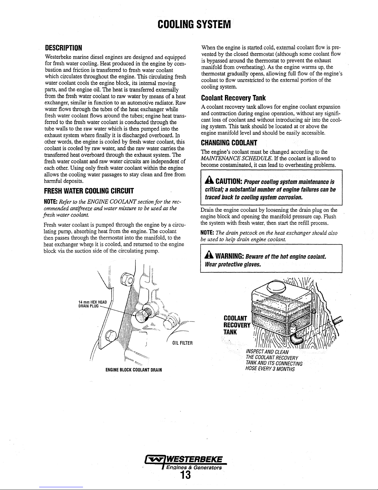
DESCRIPTION
Westerbeke
for
fresh
bustion
which
water
parts,
from
exchanger,
water
fresh
ferred
tube
exhaust
other
coolant is cooled
transferred
fresh
·
each
allows
harmful
FRESH
NOTE:
ommended
fresh
Fresh
lating
then
heat
block
marine
water
cooling.
and
friction
circulates
coolant
and
the
flows
water
to
walls
system
words,
water
other.
the
deposits.
WATER
Refer
water
water
pump,
passes
exchanger whete it
via
throughout the engine. This circulating
cools
the engine
fresh
water
similar
through
coolant
the
fresh
water coolant is conducted
to
the
raw
where
the engine
by
heat
overboard
coolant
Using
only
cooling
water
COOLING
to
the
ENGINE
antifreeze
coolant.
coolant
absorbing
through
the
suction
diesel
engines are
Heat
produced
is
transferred
the
engine
block,
oil.
The
heat
coolant
to
in
function
the
flows
water
raw
and
to
tubes
of
around
which
finally
it is discharged
is
cooled
water,
through the exhaust
raw
water circuits
fresh
water coolant
passages
CIRCUIT
COOLANT
and water
is
pumped
the
side
through
heat
from
thermostat into the
is
cooled,
of the circulating
designed
in
the
engine
to
fresh
water
its
internal
is
transferred externally
raw
water
by
means
an
automotive
the
heat exchanger
the
tubes;
engine heat
through
is
then
pumped
overboard.
by
fresh
water
and the
raw
water
are
within
to
stay
clean
section
mixture
to
be
the
the engine.
and
returned
engine
The
manifold,
pump.
COOLING
and
equipped
by
com-
coolant
fresh
moving
of
a heat
radiator.
coolant,
syste~.
independent of
and
for
used
to
Raw
while
trans-
the
into the
In
this
carries the
The
the engine
free
from
the
rec-
as
the
by
a circu-
coolant
to
the
the
engine
SYSTEM
When
the
engine
is
started cold, external coolant
vented
by
the
closed thermostat (although
is
bypassed
manifold
thermostat
coolant
cooling
Coolant
A coolant
and
cant
ing
system.
engine
CHANGING
The engine's coolant
MAINTENANCE
become
A
critical; a substantlal11umber
traced
D~n
engme
the
system with fresh
NOTE:
be
used
A
Wear
around
from
overheating).
gradually
to
flow
unrestricted
system.
Recovery
recovery
contraction
loss
manifold
during
of coolant
This
tank
level
COOLANT
SCHEDULE.
contaminated, it
CAUTION:
back
the
engine coolant
block
The
to
and
drain
help
Proper
to
cooling
opening
petcock
drain
WARNING:
protective
gloves.
the
thermostat
As the engine
opens,
allowing
to
Tank
tank
allows
engine operation, without
and
without
should
and
should
must
be
can
cooling
system
by
loosening the
the
water,
then
on
the
engine
Beware
of
some
to
prevent the
warms
full
flow
the
external
for
introducing air
be
located at or
be
changed according
If
the coolant
lead
to
system
of
portion
engine coolant
above
easily
accessible.
overheating
malllfenance
engine
failures
corrosion.
drain
manifold pressure
start the
heat exchanger
coolant.
the
bot
refill
engine
flow
is
coolant
exhaust
up,
the
of
the
engine's
of
the
expansion
any
signifi-
into
the
the
to
the
is
allowed
problems.
can
plug
on
cap.
Flush
process.
should
coolant.
pre-
flow
cool-
to
is
be
the
also
ENGINE
BLOCK
~
COOLANT
DRAIN
IW'/WESJERBEKE
· f
En_Qines
.
& Generators
13
COOLANT
RECOVERY
TANK
t
INSF}ECT
AND
THE
COOLANT
TANK
AND
HOSE
EVERY 3 MONTHS
CLEAN
RECOVERY
ITS
CONNECTING.
Page 20

CHANGING
Close
and
gasket
pliers.
Lightly
Install
of
the
cover.
THE
the
raw
or
0-rlng
Carefully
coat
the
the
new
curve
of
Open
the
water
pry/pull the impeller out of
inside of
impeller,
the
raw
RAW
WATER
intake
With
the
bending
cam
plate.
water
valve.
Remove
the aid of
pump
the
Re-assemble
intake
valve.
PUMP
IMPELLER
the
two
screwdrivers
housing
blades
the
RAW
WATER
COOLING
pump
cover
or
the
pump.
~ith
glycerine.
in
the
direction
gasket
and
".
PUMP
SYSTEM
:NOTE:
Also
a
[/round.
If
.the
engine temperature
norinal
reading,
may
have been caught
raw
water through
WASHER
follow
the
the
cause
the
above
gauge
may
up
in
cooling
RAW
procedure
ever
shows
be
that silt, leaves
the
strainer,
system.
WATER
after
having
a higher
or
slowing
the
STRAINER
nm
than
grass
flow
hard
of
INSPECTION:
EACH
REPLACE
ANY'CRACKS.
CHECK
BLADE
BY
BENDING
THE
IMPELLER
A
CAUTION:
Impeller,
cooling
exchanger.
Raw
Water
NOTE:
Always
the
strainer
A
clean
engine's
strainer
in
'the
glass
Perform
operation:
1.
Close
2.
Remove
3.
Clean
4.
Replace
s.
Reassemble
6.
Open
7.
Run
fflE
they
circuit.·
Intake
will
raw
water
cooling
when
making
should
the
following
the
raw
and
the
glass.
the
the
seacock.
the
engine
install
BASE
OF
VIGOROUSLY.·
IF
If
any
of
must
be
found
They
often
Strainer
the
strainer
always
be
intake strainer
system.
washer
and
be
water
clean
install
and
your
clear.
Include a
maintenance
seacock.
the
if
necessary.
check for
self-priming.
periodic
strainer
the
the
can
strainer.
vanes
to
prevent
be
found
at
or
is a vital
visual
engine
after
filter.
leaks.
have
broken
blockage
In
the
below
the
component of
inspection of
check.
every
off
In
heat
waterline
The water
100
hours
the
the
the
this
of
so
TYPICAL
HEAT
EXCHANGER
The
heat exchanger is a
number
the
engine
removes
of small copper
small
copper
is circulated
heat from
CLEAN
DEBRIS
Ci.EANd.Jr
DEBRIS
BOTH
RAW
(OWNER
tuJ?es
and
around
the
fresh
AT
ENDS
WATER
INTAKE
STRAINER
INSTALLED)
copper
cylinder which encloses a
tubes.
Raw
water
the
fresh
water
the
copper
tubes.
water
coolant.
HEAT
EJ{CHANGER$
AWJAVA/LABLE
CUPRO·NICKEL
TUBING
is
pumped
coolant
The
ARE
WITH
from
raw
through
the
water
t-w-IWESTERBEICE
l
Engines & Generators
14
Page 21

COOLING
SYSTEM
Refilling
After
the
replacing
Coolant
the
engme block drain plug, close the heat
exchanger's coolant petcock. Then pour clean, premixed
coolant
into
the
manifold
the
manifold,
NOTE:
When a steady flow
the petcock and fill the system until the manifold remains
Monitor
the
manifold
sure
cap.
Remove
coolant
the
cap.
flow
into
After
checking
Coolant
engine
needed.
TO
RECOVERY
MAKE
CERTAIN
PASSAGES
ARE
FROM
RECOVERY
start
Open the air-bleed petcock
the
coolant
to
the
the
cap
on
mix
to
halfway between
Run
the
engine and observe the coolant expansion
the
recovery tank.
for
should draw back
cools
down.
Clean
up
any
COOLANT
TANK
THESE
KEPT
CLEAR
COOLANT
TANK
and
when
the
coolant
tl1e
engine.
on
the heat exchanger.
of
coolant appears
in
the
manifold
filler neck
and
and add
install
at
the
the coolant recovery tank
LOW
and
leaks,
stop
ilie engine
into
Add coolant
the
to
and
cooling system
the
recovery tank if
spilled coolant.
the petcock, close
as
manifold pres-
and
MAX
allow
is
visable
full.
needed. Fill
fill
wiili
and
replace
it
to
cool.
as
the
in
Replacing
Remove
ing
as
ket,
apply a thin
before
the
cap
shown.
pressing
the
screws.
Run
the
engine
there
are
no
leaks
GASKET
THERMOSTAT
ASSEMBLY
Thermostat
screws
and
When
installing
coat of sealant
it
into
place.
and
check
at
the
thermostat housing.
disassemble
the
on
Do
not over-tighten
for
normal
the
new
thermostat
both
sides
temperatures
thermostat
and
of
the
gasket
the
cap
and
BLEED
PETCOCK
COOLANT
TEMPERATURE
SEND
!OPTIONAL)
hous-
gas-
that
OR
COOLANT
NOTE:
Periodically check the condition
cap.
sure
good condition
closes tightly. Carry a spare cap.
Ensure that the upper
and
check that the vacuum valve opens
THERMOSTAT
A
thermostat,
engine,
uously
engine
from
flowing
thermostat
As
ilie
thermostat
replaced
located near
controls
flows
is
ilie coolant temperature
through the closed cooling circuit. When
first
started, the closed thermostat prevents coolant
(some coolant
to
prevent
engine
warms
is
accessible
easily.
Carry a spare thermostat
the
manifold
is
by-passed
the
exhaust manifold
up,
the
thermostat gradually
and
can
RETRACTION
of
the manifold pres-
and
lower rubber seals are in
SEALS
at
the
front
of
as
the
coolant contin-
through a hole
from
overheating).
opens.
be
checked, cleaned,
and
gasket.
or
the
the
and
in
The
the
RAW
WATER
The
raw
impeller
water source (ocean, lake, or river) through a hose
water
strainer.
through
the
heat
fresh
ing
the
into
ing
the
exhaust gasses. This mixture of exhaust
water
is
COOLING
water
flow
pump.
This pump draws water directly
The raw water
the
raw
water pump
CIRCUIT
is created
by
passes
to
exchanger tubes) where
water coolant. The
raw
water-injected exhaust
discharged overboard
by
a positive displacement
from
from
the
strainer
the
heat exchanger
it
cools
the
engine circulat-
water
is
then
discharged
elbow,
mixing with
gas
the
engine's exhaust
the
to
the
(through
and
cool-
and
raw
gas
discharge pressure.
Raw
The
Water
raw
Pump
water pump
is
a self-priming, rotary
pump
with
non-ferrous housing and a neoprene impeller. The impeller
has
flexible
within
On
no
lubricant
impeller
Raw
water)
are
not
raw
NOTE:
(seals and bearings), it may be
chase a
vanes
which
wipe
against a curved
the
impeller housing, producing
account should this
for
the
impeller. There should always
and
impeller cover gasket
water
pump
impeller failures occur
is
not
present during engine operation. Such
warrantable, and operators
water
flow
is
present
Should a failure occur with the pump
new pump
pump
be
run
(an
are
cautioned
at
start-up.
more cost efficient
and
rebuild the original pump as a spare.
earn
fue
pumping
dry
as
water
be a spare
impeller kit)
when
lubricant
to
:s-
internal parts
plate
action.
acts
aboard.
failures
make
to
pur-
(raw
raw
a
as
sure
a
Engines & Generators
15
Page 22

Zinc
Anode
A
zinc
anode,
or
pencil,
circuit
within
the
zinc
anode
is
to
sacrifice
place
in
the
raw
water
effects
of
electrolysis
The
condition
det~rmine
replacement
Spare
zinc
NEW
NOTE:
installation
of
its
service
period
anodes
REPLACE REPLACE
Electrolysis
and vessel location; not that
heat
the
zinc
life.
can
should
ZINC
action
on
is
located
exchanger.
itself
to
cooling
circuit,
other
components
should
Once
that
be
noted
be
carried
ANODES
is
the result
in
the
raw
The
purpose
electrolysis
thereby
be
checked
is
established,
in
your
maintenru;tce
on
board.
of
each
of
COOLING
water
cooling
of
having
the
action
taking
reducing
of
the
monthly
ClEAN
REUSE
particular
the
engine.
system.
to
the
zinc
log.
AND
the
SYSTEM
If
the
zinc
anodes
need
replacement,
which
the
zinc
anode
is
threaded
ening
the
anode
with
another
b~ss
from
possibly
removing
poor
the
clean
exchanger
aged
to
ber),
NOTE:
do
insulate
ing
Heat
After
and
motive
exchanger.)
NOTE:
that a heat exchanger cleaning
every
the
condition,
exchanger.
the
inside
end
when
removing
your
engine
0-ring
The,
threads
.not
require
the
preventing electrolysis action
Exchanger
approximately
pressure
radiator
Operating
1
ooo·
hours.
tearing
zinc,
note
the
there
are
probably
Remove
gasket
model's heat
and
sealant.
zinc from
the
of
all
zinc
in
case
the
end
cover,
and
of
the
zinc anodes
Sealant should not be used
the
metal
Service
1000
test
the
engine's
shop
should
in
silty and/or tropical waters
with a wrench
wrench.
off
the
exchanger
condition
a lot of
end
of
the
debris.
Always
the
present
cover.
exchanger
install a new
of
the
on
hours
of
operation,
heat
exchanger.
be
able
be
performed
hold
the
hex
This
prevents
shell.
of
it.
If
the
zinc
flakes
heat
exchanger
have a spare
one
becomes
Replace
to
the
end
gasket
zinc
anode.
are
pipe
threads
heat exchanger
the
zinc.
remove;
(A
clean
and
may
more
boss
while
the
After
zinc
gasket
part
as
local
test
the
require
often
into
loos-
hex
is
in
within
and
heat
dam-
(refer
num-
and
it
may
hous-
clean
auto-
heat
than
AIR
INTAKE
The
function
pulsat~ng
operatmg.
Th~
air
mamtenance
of
any
SILENCER
of
the
air
intake
intak~
silen~er
It
reqUires
obstructions
air intake silencer is
noise
to
produced
has
is
that
air
flow
no
filter
the
into
by a diesel
element
inlet
the
AIR
INTAKE
to
reduce
engine
inside.
opening
silencer.
be
the
The
kept
SILENCER·
while
only
clear
AIR
INTAKE
SILENCER
Engines & Generators
.
16
.
Page 23

FUEL
SYSTEM
DIESEL
Use a diesel
J
ASTMD975.
313
.filii.
and
has
fuel
that meets the requirements of No.2-D SAE
a cetane rating
of
45
or higher according to
DESCRIPnON
Fuel is drawn into the engine's fuel system by the electric
fuel
pump mounted on the generator's drive engine. Fuel
is drawn from the fuel tank through the primary
filter/water separator through the
pressure
mounted on the engine. Fuel passes through this filter
fuel injection pump where the injection pump delivers it
the mjectors, The fuel serves three purposes in the system. It
is
from the injection equipment through the return back
fuel
FU~L
(6-8
psi) and delivered
used for combustion, lubrication and carries heat away
tank where it
SYSTEM
is
dissiPated in the cool fuel in the
DIAGRAM
fuel
pump, then under
to
the secondary
(TYPICAL)
fuel
fuel
fi,lter
to
to
tank.
the
to
the
;PRIMARY
tO
.
FUEL
FILTER
WATER
SEPERATOP
A primary fuel filter
installed between the fuel tank and
water and other contaminant's from the
be carried to the
A typical fuel filter/water separator
is
the Raycor Model500 MA.
separator
tank and engine-mounted fuel system, any water in the
will affect the fuel pump, engine
equipment The owner/operator
certain the
free
and maintaining a proper filtration/separation
type filter
~1
of iniplirities.
SECONDARY
Change the filter element
operation then follow the MAINTENANCE
in
~s.manual.
of
the water separating type must be
fuel
system on the
is
not installed between the
reaching the engine's injection equipment is
This
ON-ENGINE
:-L.II--~J
the engine
~ngine~_
is
Keep
in mind that
filter,
is responsible for
process is accomplished by installing
FUEL
FILTER
after
the initial 50 hours
MICRON
ELEMENT
RECOMMENDED
fuel
before
illustrated
and injection
SCHEDULE
to
remove·
they
below.
if
a water
fuel
making
system.
of
can
This
supply
fuel
FOB.
SYSTEM
All
WESTERBEKE
INSTALLATIONS
FUELJWATER
ENGINE/GENERATOR
REQUIRE
AN
SEPARATOR
OWNER-INSTALLED
Changing
1. Shut the fuel supply
2.
Unscrew the retaining ring that holds the filter
housing and allow the bowl to come away from the
ing. Hive some absorbent towels under the bowl to catch
any
3. Remove the filter element. Replace the
element
4. Replace the large sealing
Reassemble the bowl
ring on carefully
retaining ring contacts the
by hand. Turn
the preheat circuit Then run the engine and inspect for
anyleaks.
fuel.
The
fit
on
Fuel
Filter
Element
off.
"0"
to.
Clean the bowl. - · ·
"0"
ring. Install a new
to
the housing. Thread the retaining
so
as
not to cross thread. When the
"0"
ring, tighten 1/4-1/2 turn
on
the fuel supply
·
and
bleed the engine via
bowl
ring that the
e~ement
to
the
hous-
{~IWESTERBEKE
l
Engi~~
.
!ft
Generators
17
FUEL
FILTER
SECONDARY
Page 24

FUEL
LIFT
PUMPS
Two
types of
same
electromagnetic principle. Earlier model
pump
lift
changed at regular maintenance intervals
Later model engines
require maintenance. Electrical connections
clean and tight
When
will
purge air
flow
of fuel
fuel
lift
pumps
with a replaceable element.
use
a smaller left pump
with
either
pump.
energized
as
thru
from
the
the
preheat circuit,
the
fuel
engine
system
is
running.
are
shown,
both operate
This
(at
the
and
provide a continuous
FUEL
dn
the
engines
element should
250
that
should
fuel
use
hours).
does
not
be kept
lift pump
SYSTEM
a
be
TO
PRIMARY
fUELRL~
TO
PRIMARY
·fiLTER
FUEL
SOLID
STATE
LIFT
PUMP>
(LATER
MODELS)
FUEL
LIFT
PUMPS
Engines & Generator.s
18
Page 25

ENGINE
LUBRICATING
OIL
ENGINE
SUMP
DRAIN
HOSE......,_,___..._
1. Draining the Oil Sump. Discharge the used oil through
the sump drain hose (attached to the front
while the engine is wann. Drain the used oil completely,
replace the hose in its bracket, and replace the end cap
securely.
NOTE:
Thread
is
114
NPT.
DRAIN
THE
FI
U"ER
REMOVING
FROM
SPIN
OIL
2. Replacing the Oil Filter. When removing the used oil fil.
OIL
BEFORE
THE
THE
HOUSING
ON
FILTER
ter, you may find it helpful and cleaner to punch a
the upper and lower portion
oil from it into a container before removing
to lessen spillage. A small automotive filter wrench
should be helpful in removing the old oil filter.
NOTE:
Do
filter
to
Place some paper towels and a plastic bag around the
ter when unscrewing
(Oil or any other fluid on the engine reduces the engine's
cooling ability. Keep your engine clean.) Inspect the old
oil filter
sealing gasket comes off with the old oil filter.
ber sealing gasket remains sealed against the filter
bracket, gently remove it.
FROM
THE
FILTER
TWiN
!·/AND
O·RING,
213
OF A TURN.
size for
TIGHT
THEN
the
lube
AGAINST
TIGHTEN
of
not punch this hole without first
make
certain it
as
it
is removed to make sure that the fllbber
can
be
it
to catch any oil left in the filter.
OIL
CHANGE
FOR
EXTENSION
1/4"
NPT
6"0.D.
of
the engine)
oil drain
the old filter to drain the
hose
AP.I'LY
CLEAN
ENCi/NE
WHEN
JNSTALL/tvG
loosening
capped
OIL
hole.
it.
'Ibis helps
the
removed.
If
this rub-
end
fil-
in
NOTE:
Generic filters
ial
standards
parts might
or diameters
be
Immediately after
engine
to
make
there
are
no
oil leaks around
3. Filling the Oil Sump. Add new oil through the oil filler
cap on the top
After refilling, run the engine for a few moments while
checking the oil pressure. Make sure there is
around the new oil filter or from the oil drain system, and
stop the engine. Then check the quantity
lube oil dipstick. Fill to, but not over the high mark on
the dipstick, should the engine require additional oil.
OIL
PRESSURE
The lubricating system is a pressure feeding system using
an oil pump.
the oil pump, which drives the oil, under pressure, through
the oil filter, oil cooler and various lubricating points in the
engine. The oil then returns to the oil sump to repeat the
continuous cycle. When the oil pressure exceeds the
fied pressure, the oil pushes open the relief valve in the oil
pump and returns to the oil sump, keeping the oil pressure
withln its specified range.
The engine's oil pressure, during operation, is indicated
by
the oil pressure gauge on the instrument panel. During
normal operation, the oil pressure will range between
60 psi (2.8 and 4.2 kg/cm
NOTE:
reading
an
oil
readings
engine
LOW
The specified safe minimum oil pressure is 4.3 + 1.4 psi (0.3
+ 0.1 kg/cm
a worn bearings.
sure readings, see the
The
A
newly
started,
up
to
60 psi
pressure
reading
will vary
and
the
rpms.
OIL
PRESSURE
2
).
A gradual loss
are
not
recommended,
of
important items
entirely different
an
oil filter change and oil
sure
the
of
the engine or through the side oil
engine oil is drawn from the oil sump by
2
).
cold
(4.2
kg!crrf).
as
low
depending
For
additional information on low oil pres-
ENGINE
from
oil
pressure
engine
the
·can
is
new oil
have
A warmed engine
as 35 psi (2.5 kg/cm
upon
the
temperature
of
oil pressure usually indicates
TROUBLESHOOTING
genuine
normal
filter.
of
an
as
the
mater-
on
generic
parts.
fill,
run
and
that
fill.
no
leakage
oil with the
speci-
40 and
oil
pressure
can
have
2
).
These
of
the
chart.
the
Q)l~
·--~~hl
When installing the new oil filter element, wipe the filter
gasket's sealing surface on the bracket free
apply a thin coat
on the new oil filter. Screw the filter onto the threaded oil
filter nipple on the oil filter bracket, and then tighten the
filter firmly by hand.
of
clean engine oil to the rubber gasket
of
oil and
19
N.OTE:
To
gauge
as
sure
gauge.
or
more
test the oil
shown.
Oil
Pressure should
at 1800
pressure,
Warm
rpm.
install a mechanical pressure
up
the
engine and
be
read
35.0 lb/in2 (3.8 Kg!cnt)
the
oil pres-
Page 26

ALTERNATOR
The charging
with
a voltage regulator, an engine
Il),OUnted
cables. Because of
electronic
internally or
system
DC
circuit breaker and a
the
voltage
regulator
on
the
back
50
AMP
ALTERNATOR
consists
use
DC
of a DC
of integrated circuits (IC's),
is
very
of the alternator.
belt driven alternator
DC
wiring
harpess,
battery
with
connecting
compact
and
ELECTRICAL·
a
the
is
mounted
SYSTEM
1.
Start
the
2.
After
starting
multimeter
a. If
the
tor
to
"Checking
b.If
the
exists
continue
engine.
the
engine
has
run
for
a few minutes,
battery
voltage
at the battery terminals
set
on
DC
volts.
voltage
is
increasing toward 14 volts,
is
workingi
voltage
with
MUlTIMETER
omit
Steps 3 through 8 and
the
Service Battery"
remains around 12 volts, a problem
either the alternator or the charging
with
Steps
3 through
8.
on
the
measure
using
the
alterna-
go
directly
next
page.
circuit;
the
a
ALTERNATOR
A
WARNING:
hot.
Do
Use
this
exists
with
determined that
have
a qualified
The alternator charging circuit charges
and
the
service
or a battery selector switch
to
isolate the
along
with
starting
the
Testing
battery
service battery's charging circuit and not
tor.
A
CAUTION:
that
everyone
sheaves
A
WARNING:
DC
Bnd
applicationS.
isolate
before
made
without a proper
TROUBLESHOOTING.
A
failed
alternator
not
touch
until
the
alternator
troubleshooting
the
charging
the
technician
battery.
batteries
the
service
but
the
Alternator
Is
and
belts
AC
circuits
Always
DC
and
AC
performing
section
to
determine if a
circuit or
alternator or voltage regulator
An isolator
so the starting battery
battery
not
the service
Before
starting
clear
of
during
When
testlqg
are
often
with
check
il
with
is
usually mounted
..
If
the
battery,
the
moving
parts!
test
procedures.
with a multlmeter:
mixed
disconnects
converters,
DC
testing.
and
No
AC
knowledge
alternator is
can
become
has
the·alternator. If it is
the
starting
a diode, a solenoid
the
engine
Keep
together
shore
power
shut
down
tests
of
AC
circuits.
very
cooled
down.
problem
is
faulty,
battery
in
the
is
not
discharged
charging
problem is in
with
the
make
certain
away
in
marine
cord,
the
engine
should
be
circuit
the
alterna-
from
TESTING
THE
STARTING
BATTERY/ALTERNATOR
(ENGINE
3.
4.
5.
6. Check the battery voltage.
TESTING
BATIERY • ENGINE
RUNNING)
Turn
off
the
engine
..
Inspect all wiring
Ensure
that
the
battery
terminals
connections
A
charging
switch
If
a battery selector switch is in the charging circuit,
ensure that it is on the correct battery.
Tum
condition, the reading should be
THE
are
tight
and clean.
CAUTION:
when
off the battery switch.
circuit,
the
To
avoid
never
engine
STARTING
damage
shut
off
is
running/
If
the battery
and
the
12
the
to
to
OFF
and
connections.
engine
the
battery
engine
is
in good
13
volts.
ground
battery
Engines & Generators
20
Page 27

7.
Now
minal
the
tor
neither
between
connections
check
(B+)
alternator
is
in
the
of
the
the
the
voltage
and
ground.
will
be
circuit
above
alternator
- look
between
If
the
the
same
the
alternator
is
true, a problem
and
the
for
an
opening
DC
the
alternator output
circuit
is
good,
as
the
battery,
voltage
exists·
battery.
Check
in
the
MULTIMETER
ELECTRICAL
ter-
the
voltage
at
or if
an
isola-
will
be
zero.
If
in
the
circuit
all
the
charging
circuit.
az5J
e
OM
SYSTEM
Checking
Check
have a voltage
running. If not, there
charging circuit.
circuit
isolator, battery
the
Service
the
voltage of
between
Troubleshoot
by
checking
switch,
MULTIMETER
CKID
Battery
the
service
13
and
is a problem
the
wiring
and
the
battery.
14
the
and
battery itself.
This battery
volts
when
the
in
the
service battery
service battery charging
connections,
the
should
engine
solenoid,
i~
TESTING
THE
STARTING
BATTERY/ALTERNATOR
(ENGINE
8.
Start the engine
alternator output
The
voltage
should
is
over-
service
NOTE:
voltmeter
at
the
tery
yoltage
If
12
wiring
12
VOLT
The
engine
shown on
diagrams
electrical
A
CAUnON:
circuit,
.
the
engine
hOWBVIIr,
engine's
RUNNING)
again.
and
reading
be
between
or under-cha!ging,
facility.
Before
to
EX.C
volts
is
and
DC
CONTROL
has a 12
the
wiring diagrams that
when
system.
never
Is
to
avoid
electrical
13.5
removing
ensure
tenninal if
at the B
not
present
look
for
volt
troubleshooting
To
avoid
shut
oU
running.
electrical
circuit.
BAnERY
The
minimum
the
engine's
Cranking
recommended capacity of the battery
12
volt
DC
Amps
(CCA).
-c:::=---'
Check
the
voltage between
ground;
for
a properly operating alternator
and
14.5
volts.
If
your alternator
have
it
repaired at a reliable
the
that
12
the
output
at
breaks
alternator
volts
previous
tenninal.
the
and
for
DC
excitation
test
EXC
tenninal1 trace
po()r
r;ont)et;tions.
repair,
showed only
CIRCUIT
DC
electrical control circuit that
follow.
Refer
or
when
servicing the
damage
the
Shut
control circuit
engine
oU
the
shorts
to
the
battery
batte.ry
engine
when
is
600-900
switch.
battery
working
ENGINE
GROUND
the
use
is
present
the
to
these
DC
charging
while
switch,
on
used
Coid
a
bat-
is
the
in
TESTING
8A,rl~RY
A
CAUTION:
do
not
use a high
.
pertonning
Battery
Review the manufacturer's recommendations and
establish a systematic
engine's starting
0 Monitor your
0 Check the electrolyte
0 Use
0 Make certain that
0
Care
.engine.operation.
hydrometer.
only
level. ·
tight
to
Keep
your batteries
A
WARNING:
cauu
severe
protective
tests
distilled
the
battery
gear.
To
avoid
voltage
on
the
maintenance
batteries
voltmeter
water
batter)'
posts
Sulfuric
burns
on
damaging
test11r
(I.e. a 111egger}
alternator
and
hou.se
for
proper
level
and
to
bring
cable connections
(and
to
clean
and
free
acid
In
skin
and
schedule for your
specific gravity
da~age
THE
SERVICE
(ENGINE
.t/Je
altematoi
charging
batteries.
charg~ng
electrolytes
your engine).
lead
circuit.
during
of corrosion.
batteries
clothing.
RUNNING)
diodes,
when
then
with
to a proper
are
clean
can
Wear
a
and
Page 28

STARTER
MOTOR
DESCRIPTION
The
starter can be roughly divided into the following sections:
• A motor section which generates a drive power.
• An overrunning clutch section which transmits an arma-
ture torque, preventing motor overrun after starting.
• A switch section (solenoid) which is operated when actuating the overrunning clutch through a lever and which
supplies load current to
The starter is a new type, small, light-weight and is called a
high-speed internal-reduction starter. The pinion shaft is
arate from the motor shaft; the pinion slides only
ion shaft. A reduction gear is installed between the motor
shaft and a pinion shaft. The pinion sliding part is not
exposed outside the starter so that the pinion may slide
smoothly without becoming fouled with dust and grease. The
motor shaft is supported at both ends on ball bearings. The
lever mechanism, switch and overrunning clutch inner circuit
are identical to conventional ones.
ADJUSTMENT
If
any abnormality
should be disassembled and repaired.
Pinion
1.
2. Lightly push the pinion back and measure the return
3.
Gap
Connect a battery (12V) between the starter
and the starter body, and the pinion drive should rotate out
and stop.
A
CAUTION:
seconds
stroke (called pinion gap).
If
the pinion gap is not within the standard range, (0.5 to
2.0 rnrn), adjust it by increasing
of
shims on the solenoid. The gap is decreased as the
number
AND
Inspection
Never
continuously.
of
shims increases.
the
motor.
on
the pin-
REPAIR
is
found by the following tests, the starter
terminalS
apply
battery
voltage
or
for
over10
decreasing the number
sep-
No-Load
1.
Connect the ammeter, voltmeter, and battery to the starter
as illustrated.
2. When the switch is closed, the pinion must protrude and
A
tighten
type
that
starter
in
Test
the starter must run smoothly
the current
semble the starter and repair it.
CAUTION:
contact
or
starter speed is out
Use
thick
every
terminal
starter
which
makes a rotating
of a direct-drive
rotation
with
at
the
the
pinion
wires
securely.
type
starter.
pinion
gear
(at
3000 rpm or more).
of
specification, disas-
BATTERY
as
much
as
possible
This
is a solenoid
sound
When
detecting
tip,
be
careful
when
it
protrudes.
louder
not
to
If
and
shift·
than
come
SOLENOID
Perform the following tests.
satisfactory, replace the solenoid assembly.
1.
Inspect the solenoid for continuity between terminals
(+)and(-)
M and the body. There should be no continuity found
between terminals S and M. Continuity will be found
between terminals S and the body and terminal M and
the body.
and between terminals
If
any test result is not
Sand
the body and
0.5-2.0
mm
PINION
GAP
Engines
22
MULTIMETER
NOTE:
Disconnect
2. Connect a battery to the solenoid's terminal S for ( +)
and M
for·(-). Have a switch in the + lead and close it.
The pinion drive should extend fully out.
A
CAUTION:
than
10
seconds
&
..
CAen~ra.tors
the
Do
wire
not
apply
when
from
battery
testing
terminal
current
the
solenoid.
M.
for
more
Page 29

AnRACTION
TEST
STARTER
MOTOR
4.
Return
test:.
With a battery connected to the solenoid terminal M (
pinion fully.
when released from holding by hand.
-)
and
to the starter body, manually pull out the
The
pinion must return
to
its original position
3.
Holding
minalS(+)
pinion fully.
y.'hen
HOLDING
STARTER
1.
Disconnect the wire from the solenoid terminal M (-).
2. Loosen the
the solenoid assembly.
3. Remove the
fastening the
4. With the brushes pulled away
remove the yoke and brush holder assembly.
the armature out.
5. Remove the cover, pry the snap ring out,
washer.
6. Unscrew the bolts and remove the center bracket.
same time, the washers
adjustment will come off.
test.
With a battery connected to the solenoid ter-
and to the starter body, manually pull out the
The
pinion must remain at that position even
released from holding with your hand.
TEST
DISASSEMBLY
two
screws· fastening the solenoid.
two
long through bolts
brush
holder. Remove the
for
the pinion shaft
and
from
the armature,
two
rear
screws
bracket.
Then
and
remove ·the
end
Remove
pull
At
the
play
RETURN
TEST
BATTERY
SERVICE
WES'IERBEKE uses a standard starter motor which can
serviced or rebuilt at any starter motor automotive.service
center. Starter motors used on marine gasoline units must be
ignition protected. Use only a genuine Westerbeke
replacement starter.
7. Pull out the reduction gear lever and lever spring from the
front bracket.
8.
On
the pinion side, pry the snap ring out, and pull out the
pinion and pinion shaft.
9.
At
each end
a bearing puller.
press-fitted in the front bracket.
off, replace the front bracket assembly.
of
the armature, remove the ball bearing with
It
is impossible to replace the ball bearing
If
that bearing has worn·
be
INSPECT
FOR
WEAR & CHIPPING
STARTER·
MOTOR
TYPICAL
LEVER
SPRING
PINION
Engines & Generators
23
NOTE:
Inspect,
if
necessary
soleniJid,
following
---
clean
brush,
armature,
pages.
and
replace
conunuter,
etc.
See
the
Page 30

GLOW
PLUGS
TYPICAL
DESCRIPTION
The
glow
plugs
are
When
should
PREHEAT
"click;'
on
is
and the
INSPECTION
To
inspect
tions,
head.
soft
oil
burn
the
then
unscrew
Thoroughly
brush
and
deposits.
erosion;
plug,
clean
cleaning
While
if it
has
wired
through
pressed
glow
remove
or
unclamp
each
solution
cleaning;
eroded
NOTE:
WESTERB$KE
ments
be
performed
below
is
provided
the
preh~tsolenoid.
at
the
control
plug
should
the electrical
each
plug
plug's
tip
and
to.remove
examine
too
the
much,
ENGINE
recommends
by
a competent
to
assist
panel
this
solenoid
begin
to
get
teri:ninal
from
tip.fOI'
replace the
the
'threads
all
the
connec-
cylinder
with
carbon
wear
plug.
ADJUSTMENTS
that
the
the
hot.
a
and
and
engine
mechanic.
following
mechanic.
FUEL
In
case
injectors
injection
loss
of
in
injector
clean
injector
Before
base
of
falling
out
easily
.the
injector
free
it,
The
injector
washer.
replaced
installed.
Injector
engine
The
INJECTORS
of.severe
checked
service
positive
faults.
room
enviroment,
as
a
spare
removing
the
injector
down
into
and
is
side-to-side
and
then
seats
This
washer
with a new
to
Cylinder
adjust-
it:tformation
vibrations
and
center.
fuel
pressure
Since
should a problem
the
to
the
held
lift
it
in
Head
and
overhauled
Poor
to
fuel
injectors must
it
is
best
old
injector,
help
prevent
injector hole. If
in
by
carbon build-up
with
out.
the
cylinder
should
be
washer
Tightening
when
detonation
by
fuel
quality,
the
to
clean
the
aid
head
removed
the
Torque·
an
authorized
contaminants
injection
carry
at
occur.
the
any
rust
the
injector
of
the
on a copper
with
new
40
± 4
noise,
pump
be
serviced
least
area
or
debris
or
the
socket
the
injector
ft·lb
(5.5 ± 0.5
have
fuel
can
one
extra
around
from
will
like,
wrench
sealing
'injector
is
the
and
result
in
the
not
work
kgl·m)
a
lift
to
and
TESTING
An
accl}rate
Touch
the
other
glow
method
You
can
(8
to 9 amps
A
to
the
testing
Re-instalJ
plugs
25
seconds,
short
compound
Glow
Plug
A
than
way
one
prod
to
the
plug
will
can
be
also
WARNING:
touch.
the
the plugs
should
If the
circuit.
on
Tightening
WARNING:
30
seconds
to
to
the
body of
have a 1.0-
used
use
an
per
plug).
These
Be
careful
plugs
get
vety
plugs
When
the
threads.
Torque
Do
test
glow
glow
plug's
the
glow
to
with
the
plug in. orout of
ammeter
glow
not
in
the
engine
hot
(at the
don't heat
reinstalling
7 ·11 lb·ft
not
keep a glow
plugs
is
with
wire
plug,
as
1.5-ohm
to
plugs
to
resistance.
test thepower
Will
burn
your
and
test
tertninal
up
quickly,
the
glow
(1.0
plug
an
ohmmeter.
connection,
shown. A good
This
the
e~gine.
drain
become
fingers
them
again.
end)
within
check
plugs;
use
anti-seize
·1.5
kg·m)
on
for
more
and
very
hot
When
The
20.to
for
a
·
REFER
FOR
TESTING
to
YOI.JR
WESTERBEKE
AND
SERVICING
SERVICE
OF
FUEL
FUEL
INJECTOR
MANUAL
INJECTORS.
24
Page 31

11011:
WESTERBEKE
adjustments
infomtiltioo
ENGINE
ADJUSTMENTS
recommends
be
perftmned
be.low
iS
by
a
Provided
to
that the
competent
assist the
engine
mechanic.
following
mechanic.
engine
The .
IBEIIATORFREQUEICY-
(IIR1Z)
Once•lh¢~tg~~~~~ht~.
there
may
be
adjusttnents
during
the
engine's
this
period.
AJlO..Ioad
required
These
llOllllal
Frequency
indicated by
Wben
voltage
When
· voltage frequeaq is
1. Connect
2. Adjust
in
oonj~AllCtion
are
not.
warrantable.
break-in~
is
a
direct
tbe
followU)g:
tbe
~~
freqlleJley
tbe
generator
tbe
AC
accordance
specified
BT
GENERATOR
COJ:teSpooditig
shortening
the solenoid's plunger
solenoid.
Failure
result in a failed
To
avoid.failure
plunger
operation
linkage
throttle
throttle
withAC \bltage
for yoor
tbe
engine's
to
tbe
Throttle
· · ·
of
the
solenoid
bottoms
at the initial start-up.
joints
between
joints
between
·arm
will
required
break"in
y~adj~t._y
with
adjustments
maintenance. ·
result
of
isnmattSOOf111u.tJJe:4Cw~
is 60herlz. . . . . .
is
nm
SO
laertz. · · · ·
output~
genenuor
sed;i~oflhis
speed toObtaiatbe
tbe
vot.a,e
j\dj~~,
is
to
solenoid.
of
the
solenoid.
in
tbe
SQ)eooid.
llle
the
eliminate
for
e~ne·•spmi·~)
peri<Jd·(mst
tbe
engine~s
SO~).or
speed
as
·~••rdale
····.·•·
·...
engine/generator
· ·
...
. .
.·
•.• · .•..
at
lSOO
rpcn.
tile
to
the:
AC~tlal·b~in
~-.diagmm
sea.
Which
..
~
manual.
~
selected.
com~ly
botto1n
solenoid
solenoid
bjnding.
by
~
in
the
~
efis1d
..
~the
Periodiadly
plunger Md
plunger~
•.
~t
'·
.·
speed •
•··
•....
. . . . ·
~C
hl•tlle··
. . .
ex~
the
soienbid
soleooid•s
lUbricated
· · ·
.•
af!er
be
to
.·.
-~t
•
or
.
.sure
the
will
·
the
the
IOTE:
The solenoid plunger must move smoothly
rapidly
energized.
Set
'fo
sPeed,.of'the
monitor
method
into
the solenoid
drawing the engines
Speed/RJm
arrive
Position.
~
tbe
engine/generator
!be
frequency
being
the
when
appropriate
with a
more
precise
the solenoid
throttle
frequency,
with
frequency
of
is
electrically
ann into the
ei.ther
monitor
a tachometer or
meter.
The
the
two.
and
the
latter
DRIVE
Belt
1.
2.
BEl.tADJUS'fiVJa!T
A
CAUTION:
tensioned;
alternator
alternator~
Drive
bela
out
of
alignment
out
prematurely.
tension adjustmentis
altemator
Lcosen the
mounting
Pivot
left or right
Drive
belts
Loose
drfrle
charglnga/ld
that
are
too
and/or
on
its
base
~ternator
bolt.
the
alternator
as
required.
on
must
belt$
Will
will
eveniiJ.ally
tight
will pill/
callse.tlle
made
b)'
mounting
adjusting
the
base
b{l
prtJperly
not
alternator
pivoting
bolt.
strap
~ountiDg
providl,prtJ/J(Ir
damage
the
bolt
the
alternator
Ill
wear
th~
and
the
base
bolt
to
the
..
3.
Tighten
strap bolt.
4.
.
Operate the
shut
the
down
base
engine
and
recheck
mounting
for about 5
belt
BaT
bolt
and
minutes
tension.
TENSION
the
adjusting
at
idle,
then
Page 32

ENGINE
ADJUSTMENTS
11.0KW
VALVE
Adjust the valve clearance when the engine is cold.
0.0098 inches (0.25 mm). Tighten the cylinder head bolts to
the specified torque and sequence shown below.
1. Pull off the air breather pipe from the rocker cover, and
2. Adjust the valve clearances at
3.
NOTE:
clearance
11.0KW
BOLTS
17mm
soiTs
14mm
CLEARANCE
take off the rocker cover bolts.
each cylinder when they are on their compression stroke.
Make sure that
timing mark
If
not, the valve will interfere with the piston because
improper cam positioning.
Retighten·the cylinder head bolts before the valve
is
adjusted.
BTD&
12.5KW
5,6,7,8,9,10,11,12,13 & 14
(11.5
-12.5kg-m)
1
,2,3
& 4
(6.5-
8.0kg-m)
ADJUSTMENT
TDC (Top Dead Center)
the
timing mark on the gear case and
on
the. crankshaft pulley are exactly aligned.
BTDA
83.1-86.7
47.0-57.8
ft-lbs
ft-lbs
BTD & 12.5KW
for
of
BTD(A)
VALVE
CLEARANCE
i
. I
--=-7·
,
I
0.25MM
(0.00981NCHES)
INTAKE & EXHAUST
12.5KW
BOLTS
22mm
BOLTS 1 ,2,3
22mm
11.0KW
Rocker
14mm
10mm
12.5KW
Rocker
14mm
10mm
NOTE:
BTD
5,6,7,8,9,10,11,12,13 & 14
(15
-16kg-m)
& 4
(11 -12kg-m)
BTD & 12.5KW
Shaft
Hold
!town
(4.0 • 5.5kg-m)
(0.8
-1.2kg-m)
BTD
Shaft
Holddown
(4.0 -5.5kg-m)
(0.8
·1.2kg-m) 5.8-8.7
MM
size shown are sockets size
J
0
108.4-115.7
79.0-
86
ft-lbs
BTDA
Bolts
28.9 • 39.8
5.8-8.7
28.9 -39.8
ft·lbs
Bolts
ft·lbs
0
1
9
0
1
0
ft-lbs
ft·lbs
ft-lbs
0
5
6
0
for
holddown bolts.
0
lO
8
0
2
0
0
4
Westerbeke recommends .that these engine
adjustments
be
made
by
a.
qualified mechanic.
CYLINDER
HEAD
BOLT
liGHTENING
SEQUENCE
26
Page 33
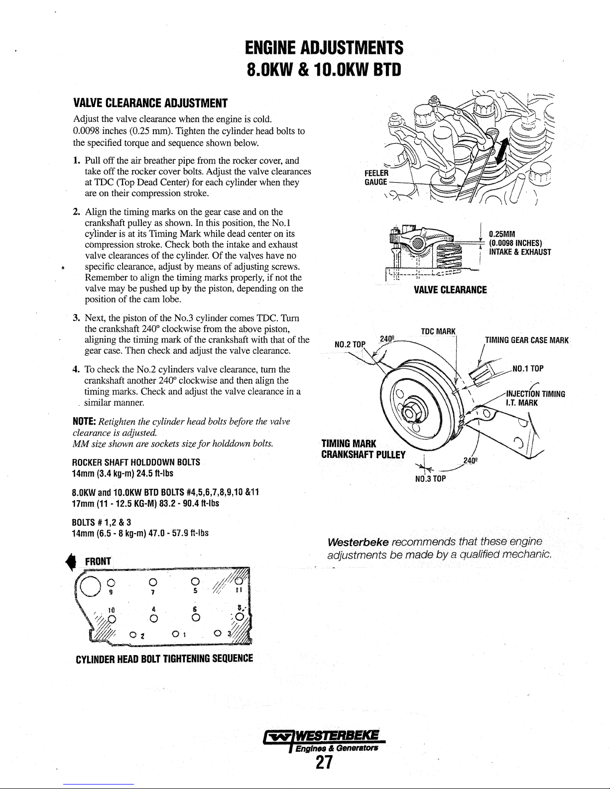
ENGINE
ADJUSTMENTS
S.OKW & 10.0KW
VALVE
Adjust the valve clearance when the engine is cold.
0.0098 inches (0.25 mm). Tighten the cylinder head bolts to
the specified torque and sequence shown below.
1. Pull off the air breather pipe from the rocker cover, and
2.
~
3. Next, the piston
CLEARANCE
take off the rocker cover bolts. Adjust the valve clearances
at
TDC
(Top Dead Center) for each cylinder when they
are on their compression stroke.
Align the timing marks on the gear case and on the
crankshaft pulley as shown. In this position, the No.1
cylinder is at its Timing Mark while dead center on its
compression stroke. Check both the intake and exhaust
valve clearances
specific clearance, adjust by means
Remember to align the timing marks properly,
valve may be pushed up by the piston, depending on the
position
the crankshaft
aligning the timing mark
gear case. Then check and adjust the valve clearance.
of
the cam lobe.
ADJUSTMENT
of
the cylinder.
of
the No.3 cylinder comes TDC. Turn
240° clockwise from the above piston,
Of
the
val,ves
of
adjusting screws.
of
the crankshaft with that
have no
if
not the
of
the
N0.2
TOP
BTD
VALVE
CLEARANCE
~
I
0.25MM
(0.0098
,
I
INCHES)
INTAKE & EXHAUST
4. To check the No.2 cylinders valve clearance, turn the
crankshaft another
timing marks. Check and adjust the valve clearance in a
. similar manner.
NOTE:
Retighten the cylinder head bolts before the valve
clearance is adjusted.
MM
size shown are sockets size
ROCKER
14mm
8.0KW
17mm
BOlTS#
14mm
SHAFT
(3.4
and
(11
-12.5
1,2
(6.5
kg-m)
10.0KW
& 3
· 8
kg-m)
240° clockwise and then align the
for
holddown bolts.
HOlOOOWN
24.5
BTD
KG-M)
BOlTS
ft-lbs
BOlTS
83.2-
90.4
47.0 · 57.9
#4,5,6,7,8,9,10
ft-lbs
ft-lbs
&11
0
7
4
0
O-z
li
0
Ot
TIMING
CRANKSHAFT
MARK
PULLEY
~
N0.3
TOP
Westerbeke recommends that these engine
be
adjustments
made
by
a qualified mechanic.
CYLINDER
HEAD
BOLT
TIGHTENING
SEQUENCE
I"W"IWESIERSEKB
l EnglnN & Generators
27
Page 34

SPECIFICATIONS
WESTERBEKE
8.0
KW
BTD
GENERATOR
Engine
Type
Governor
CornbuGtion
Chamber
Bore & Stroke
Piston
Displacement
Firing
Order
Direotion
of
Rotation
Maximum
(at
Compression
Compression
Valve
Valve
Valve
(engine
lnjeotion
Engine
Engine
Dimensions
Weight
Fuel
(approximate)
Inclination
General
Operating
Fmsh
Raw
Raw
at
System
(fresh
Torque
1800
rpm)
liming
Seat
Angle
C!Barance
cold)
Pressure
Speed
Timing
Consumption
Temperature
Water
Pump
Water
Pump
Water
Flow,
1800
rpm
Capacity
water)
Ratio
Pressure
SPECIFICATIONS
Diesel,
four-cycle,
water-cooled,
mechanism,
(14
hp
at
Mechanical,
Swirl
chamber
2.B7 x 3.07
60
cubic
1 •
3-2
Clockwise,
41.50
lb-tt
23:1
455.2
psi
Intake
Opens
Intake
Closes
Exhaust
Exhaust
Intake
45°
Exhaust
Intake
0.0098
Exhaust
1707
psi
1800
rpm
1500
rpm
19°
BTDC
Height
21.8
Width:
17.00
Length:
450
los
0.9
gph
Continuous
Temporary
COOLING
Fresh
water-cooled
controlled
170 • 190°
Centrifugal
Positive
belt-driven.
8.5
US
gpm
before
discharging
5.0
Qts
(4.73
three-cylinder,
vertical
in-line
1800
rpm
maximum).
centrifugal
type
inches
(73 x 78
inches
(0.979
when
viewed
(5.73
kg-m)
(32
kg/em')
18°
BTDC
46°
ABDC
Opens
46°
18°
inches
inches
kg/em' + 10
60
Hertz
50
Hertz
inches
inches
inches
kgs)
lph)
15°
20°
(not
BBDC
ATDC
(0.25
(552.72
(431.80
(716.28
at
full
to
Closes
45•
0.0098
(120
28.20
(204.12
(3.40
SYSTEM
block,
with
heat
exchanger.
f (77-
88°
type,
metal
displacement,
(32.2
lpm)
into
liters).
weight
liters)
from
at
280
(0.25
rated
exceed
C).
impeller,
rubber
(measured
exhaust
fresh
overhead
valve
type
mm)
the
front
rpm
mm)
mm)
kg/em' -Okg/cm'
mm)
mm)
mm)
output
20
min.)
thermostatically-
belt-driven.
impeller,
elbow).
General
Fuel
Injection
Fuel
Fuel
Injection
Nozzle
Injectors
Fuel
Pump
Fuel
Filter
Air
cleaner
Air
Flow
General
Oil
Filter
Sump
Capacity
(not
including
Operating
(engine
hot)
Oil
Grade
Starting
Battery
Battery
Capacity
DC
Charging
Regulator
Starter
Starting
Aid
DC
No-Load
DC
Cranking
Emission
Systems
Pump
Timing
(on
engine)
LUBRICATION
filter)
Oil
Pressure
ELECTRICAL
Alternator
Current
Current
EXHAUST
Control
FUEL
SYSTEM
Open
flow,
self
bleeding
# 2
D(cetane
Diesel
Nippon
19°
Throttle
Pintle
12
Volt
Canister
Metal
32
cfm
rating
grade
according
Denso
±.5°
BTDC
type
Type
DC,
Electro-Magnetic
type
screen
type -cleanable
(.906
(Bosch M Type)
(static
with
cmm)
SYSTEM
Pressure
type
external
paper
gals
psi
(2.8
10W·30
by
pressure
element,
(3.121iters).
-
or
15W-40.
with
Full
flow,
3.3
U.S.
40 • 80
API
Specification
better
SAE
SYSTEM
12-Volt,
(·)negative
400 -600
12
Internal
12-Volt,
Glow
90
175-200
Volt
DC,
plugs,
Amps
Cold
Cranking
50
Amp
regulator
1.2
~.
sheathed
max.
at
Amps
(engine
EMISSIONS
Smoke
Puff
Limiter
of
45
or
higher)
to
ASTM
D975
timing)
type
replaceable
Trichoid
5.6
CF,
built
reduction,
11.5
pump,
relief
spin-on
kg/em').
CG-4,
ground
Amps
into
type
volts
cold)
element
gear
valve
type.
CH-4,
(CCA)
alternator
solenoid
SYSTEMS
SAE
driven
Cl·4,
CJ-4
mounted
J313
or
L""'IWESIERBEKS
l
Eng!n•
& Generators
28
Page 35

SPECIFICATIONS
General
Voltage
Voltage
Regulation
Frequency
Rating
60
8.0KW
50
6.0KW
Generator
Air
(60
NOTE:
Regulation
(Volts
Hertz
(1800
Hertz
(1500
Cooling
Requirements
Hertz)
at
Increase
AC)
rpm)
rpm)
1800
air
AC
rpm
supply
WESTERBEKE
GENERATOR
Brushless,
Pre-lubricated,
Reconnectable,
regulation
(optional
120
220
±5%
±3
120
120/240
220
175-200
15%
or
1201240
Volts
no
Hertz
Volts
Volts
tor
50
four-pole,
single-bearing
single-phase
solid
state
Volts
-
50
Hertz.
load
to
full
(5%)
no
66
Volts
66/33
27
cfm
(5.66-
Hertz
operation
revolving
voltage
-
60
load.
load
to
Amps
Amps
6.37
transformer
regulator)
Hertz
full
load.
Amps
cmm)
(1500
field.
design.
rpm).
8.0
KW
BTD
Engine
Air
(60
Generator
Ambient
Recommendations
Cooling
GENERATOR
GENERATOR
Combustion
Requirements
Hertz
at
1800
RPM)
Compartment
Temperature
Air
32
cfm
104"f
NOTE:
to
mafntafn
tures
100-200
COOliNG
(.906
cmm)
(40"C)
maximum
Forced
ventilanon
gtJneratar
below
104°F
ctm
(2.83-5.66
should
compartment
(40°G).
cmm)
be
provided
temptJra-
Page 36

SPECIFICATIONS
WESTERBEKE
10.0
KW
BTD
GENERATOR
Engine
Type
Governor
Combustion
Bore & Stroke
Piston
Firing
Direction
Maximum
(at
Compression
Compression
Valve
Valve
Valve
(engine
Injection
Engine
Engine
Dimensions
Weight
Fuel
(approximate)
Inclination
General
Operating
Fresh
Raw
Raw
at
1800
System
(fresh
Chamber
Displacement
Order
of
Rotation
Torque
1800
rpm)
Ratio
Pressure
Timing
Seat
Angle
Clearance
cold)
Pressure
Speed
Timing
Consumption
Temperature
Water
Pump
Water
Pump
Water
Flow,
rpm
Capacity
water)
SPECIFICATIONS
Diesel,
four-cycle,
water-cooled,
mechanism,
(16.5
hp
Mechanical,
Swirl
chamber
3.07 x 3.07
68
cubic
1
-3-2
Clockwise,
47.71b-ft
23:1
483.5
psi
Intake
Opens
Intake
Closes
Exhaust
Exhaust
Intake
45°
Exhaust
Intake
0.0098
Exhaust
1707
psi
1800
rpm
1500
rpm
19°
Bmc
Height:
22.0
Width:
16.85
Length:
4951bs
1.0
gph
Continuous
Temporary
COOLING
Fresh
water-cooled
controlled
170-190° F (77Centrifugal
Positive
belt-driven.
7.2
US
gpm
before
discharging
8.0
qts
(7.61iters).
three-cylinder,
vertical
in-line
naturally
at
1800
inches
inches
when
(6.6
(34
Opens
Closes
45°
0.0098
(120
60
50
32.56
(224.5
(3.781ph)
20°
aspirated
rpm
centrifugal
type
(78 x 78
(1.12
viewed
kg-m)
kg/em')
18°
BTDC
45°
ABDC
46°
BBDC
18°
ATDC
inches
(0.25
inches
kg/em'
Hertz
Hert.z
inches
(558.7
inches
(427.9
inches
(826.02
kgs)
at
full
15°
(not
to
SYSTEM
block,
with
heat
exchanger.
88°
type,
metal
displacement,
(27.25
lpm)
into
maximum).
weight
liters)
from
at
230
(0.25
+ 1 0
rated
exceed
C).
impeller,
rubber
(measured
exhaust
fresh
overhead
valve
type
mm)
the
front
rpm
mm)
mm)
kg/em' -Okg/cm'
mm)
mm)
mm)
output
20
min.)
thermostatically-
belt-driven.
impeller,
elbow).
General
Fuel
Fuel
Injection
Fuel
Injection
Nozzle
Injectors
Fuel
Pump
Fuel
Filter
Air
cleaner
Air
Flow
Fuel
Lift
Pump
General
Oil
Filter
Sump
Capacity
(not
including
Operating
(engine
hot)
Oil
Grade
Starting
Battery
Battery
Capacity
DC
Charging
Regulator
Starter
Starting
Aid
DC
No-Load
DC
Cranking
.
Emission
Systems
FUEL
Pump
Timing
(on
engine)
LUBRICATION
filter)
Oil
Pressure
ELECTRICAL
Alternator
Current
Current
EXHAUST
Control
SYSTEM
Open
flow,
self
bleeding
# 2
D(cetane
rating
Diesel
grade
Nippon
19°
±
.SO
Throttle
Pintle
Type
12
Volt
DC,
Canister
Metal
screen
48
cfm
(1.36
12
Volt
DC
Dense
type
type
of
according
(Bosch M Type)
BTDC
(static
Electro-Magnetic
with
replaceable
type -cleanable
cmm)
lift
capacity
SYSTEM
Pressure
type
by
paper
gals
psi
(2.8-
Trichoid
pressure
element,
(4.51iters).
5.
kg/em').
CF,
or
15W-40.
with
external
Full
flow,
4.76
U.S.
40 -80
API
Specification
better
SAE
10W-30
SYSTEM
12-Volt,
(-)
negative
ground
400 -600
12
Internal
12-Volt,
Glow
90
175-200
EMISSIONS
Smoke
Volt
plugs,
Amps
Cold
Cranking
DC,
50
Amp
regulator
1.6
i<J/1/,
sheathed
max.
at
Amps
(engine
Puff
Limiter
built
reduction,
11.5
SYSTEMS
45
or
to
ASTM
timing)
5'
(1.5m)
pump,
relief
spin-on
CG-4,
Amps
into
type
volts
cold)
higher)
SAE
D975
type
element
gear
valve
type.
CH-4,
Cl-4,
(CCA)
alternator
solenoid
J313
driven
CJ-4
or
mounted
Page 37

Single
Phase
Voltage
Voltage
Regulation
Frequency
Rating
60
10.0
50
7.51W'/
Generator
Air
(60
NOTE:
Regulation
(Volts
Hertz
(1800
IW'I
Hertz
(1500
Cooling
Requirements
Hertz)
at
Increase
AC
GENERATOR
Brushless,
Pre-lubricated,
Reconnectable,
regulation
(optional
120
220
±5%
±3
AC)
rpm)
rpm}
1800
air
rpm
supply
120
1201240
220
225 -250
15%
SPECIFICATIONS
WESTERBEKE
or
1201240
Volts • 50
no
load
Hertz
Volts
Volts
for
50
SINGLE
four-pole,
solid
(5%)
Volts
cfm
Hertz
PHASE
revolving
single-bearing
single-phase
state
voltage
Volts·
60
load.
load
to
full
83.3
Amps
83.3/41.6
34.1
Amps
6.37
(1500
Hertz
Hertz.
to
full
no
(5.66-
operation
transformer
regulator)
load.
Amps
cmm)
10.0
field.
design.
rpm).
KW
BTD
Three
10.0
IW'I·
7.5
IW'I · 50
Voltage
(60
Hertz)
Voltage
(50
Hertz)
Amperage
(60
Hertz)
Amperage
(50
Hertz)
Engine
Air
Requirements
(60
Hertz
Generator
Ambient
Recommendations
Cooling
GENERATOR
AC
GENERATOR
Phase
60
Hertz
Hertz
• 3
Phase
-3
Phase
-3
Phase
-3
Phase
Combustion
at
1800
Compartment
Temperature
Air
RPM)
Brushtess,
lubricated
reconnectable
voltage
Delta.
protection
Low
vottage
High
voltage
DELTA
High
voltage
DELTA
Low
voltage
High
vottage
DELTA
High
voltage
DELTA
GENERATOR
32
cfm
(.906
104•F
{40°C)
NOTE:
Forced
to
maintain
tures
below
10o-200
THREE
six-pole,
single
circuitry.
bearing
for
Solid
WYE
WYE
WYE
WYE
WYE
WYE
PHASE
revolving
low
voltage
state
COOLING
cmm)
maximum
ventilation
generator
cfm
t04•F
(4o•c).
(2.83·5.66
compartment
field.
design.
WYE,
voltage
208
·
480
240
380
220
35Amps
15Amps
30Amps
14Amps
24Amps
should
cmm)
Sealed
121ead
high
regulator
volts
volts
volts
volts
volts
be
provided
tempera-
with
Page 38

SPECIFICATIONS
Engine
Type
Governor
Combustion
Bore & Stroke
Piston
Firing
Direction
Maximum
(at
Compression
Compression
Valve
Valve
Valve
(engine
Injection
Engine
Engine
Dimensions
Weight
Fuel
(approximate)
Inclination
General
Operating
!=resh
Raw
Raw
at
1800
System
(fresh
Chamber
Displacement
Order
of
Rotation
Torque
1800
rpm)
Ratio
Pressure
Timing
Seat
Angle
Clearance
cold)
Pressure
SpeM
Timing
Consumption
Temperature
Water
Pump
Water
Pump
Water
Flow,
rpm
Capacity
water)
WESTERBEKE
SPECIFICATIONS
Diesel,
four-cycle,
water-cooled,
mechanism,
(18.4
hp
Mechanical,
Swirl
chamber
2.87 x 3.07
80
cubic
1-3·4
Clockwise,
54
lb·ft
(7
23:1
455
psi
(32
Intake
Opens
Intake
Closes
Exhaust
Exhaust
Intake
45°
Exhaust
Intake
0.0098
Exhaust
1707
psi
1800
rpm
1500
rpm
19°
BTDG
Height:
23.75
Width:
16.85
Length:
34.56
5751bs
(260.8
1.2
gph
Continuous
Temporary
COOLING
Fresh
water-cooled
controlled
170c
-190°
Centrifugal
Positive
belt-driven.
7.2
US
gpm
before
discharging
8
qts
(7.61iters).
three-cylinder,
vertical
in-line
at
1800
rpm
maximum).
centrifugal
type
inches
(73 x 78
Inches
(1.3051iters)
·2
when
viewed
.46
kg-m)
kg/em')
at
280
18°
BTDC
46"
ABOC
Opens
46°
60
50
15•
20"
inches
inches
kg/cm
Hertz
Hertz
inches
inches
inches
kgs)
at
(not
BBDC
ATDG
(0.25
2
+
(603.25
(427.99
(877.82
full
to
exceed
Gloses18°
45•
0.0098
(120
{4.541ph)
SYSTEM
block,
with
heat
exchanger.
F (77•-
sa•
type,
metal
displacement.
(27.251pm)
into
·
weight
(0.25
10
impeller,
rubber
exhaust
11.0
fresh
overhead
valVe
type
mm)
from
the
front
rpm
mm)
mm)
kg/cor-
Okg/cm
mm)
mm)
mm)
rated
output
20
min.)
thermostatically-
C).
belt-driven.
impeller,
(measured
elbow).
2
KW
General
Fuel
Fuel
Fuellnjec+Jon
Nozzle
Injectors
Fuel
Fuel
Air
AirFlow
General
Oil
Sump
(not
Operating
(engine
Oil
Starting
Battery
DC
Regulator
Starter
Starting
DC
DC
Emission
Systems
BTD
GENERATOR
Injection
Pump
Filter
(on
cleaner
Filter
Capacity
Including
Oil
hot)
Grade
Battery
Capacity
Charging
Alternator
Aid
No-Load
Current
Cranking
Current
EXHAUST
Control
FUEL
Open
# 2
Diesel
Pump
Timing
engine)
Nippon
19•
Throttle
Pintle
12
Canister
Metal
42.
lUBRICATION
Pressure
with
Full
filter)
Pressure
4.23
40 • 80
API
better
SAE
ELECTRICAL
12-Volt,
400 • 600
12
Internal
12-Volt,
Glow
90
175·200
EMISSIONS
Smoke
SYSTEM
flow,
self
D(cetane
rating
grade
according
Denso
(Bosch M Type)
±
.s•
BTDC
type
Type
Volt
DC,
Electro-Magnetic
type
with
screen
type -cleanable
cfm
(1.2
cmm)
SYSTEM
type
by
external
pressure
flow,
paper
u.s.
gals
(4.0
psi
(2.8 -5.6
Specification
10W·30
or
SYSTEM
(·)
negative
Cold
Volt
DC,
50
regulator
1.6
KW,
plugs,
sheathed
Amps
max.
Amps
Puff
Limiter
bleeding
of
45
or
higher)
to
ASTM
(static
timing)
replaceable
Trichoid
pump,
relief
valve
element.
spin-on
liters).
kg/em>).
CF,
CG-4,
CH-4,
15W·40.
ground
Cranking
Amps
Amp
built
into
alternator
reduction,
at
{engine
11.5
solenoid
type
volts
cold)
SYSTEMS
0975
type
element
gear
type.
C1·4,
(CCA)
SAE
J313
driven
CJ-4
mounted
or
Page 39

SPECIFICATIONS
Single
Phase
Voltage
Voltage
Regulation
Frequency
Rating
(Volts
60
Hertz
(1800
11.0
KW
50
Hertz
(1500
6.3KW
Generator
Air
(50
NOTE;
Cooling
Requirements
Hertz)
at
Increase
Regulation
AC)
rpm)
rpm)
1
BOO
rpm
air
supply
WESTERBEKE
Brushless,
Pre-lubricated,
Reconnectable,·
regulation
(optional
120
220
:t5%
±3
120
120/240
220
200 -225
15%
solid
or
120/240
Volts -50
no
load
Hertz
(5%)
Volts
Volts
Volts
for
50
Hertz
four-pole,
single-bearing
single-phase
state
voltage
Volts -60
Hertz.
to
full
load.
no
load
91.5Amps·
91.6/45.8
37.7
cfm
(5.66 -6.37
operation
revolving
transformer
regulator)
Hertz
to
full
load.
Amps
Amps
cmm)
(1500
design.
field.
rpm).
11.0
.
KW
BTD
Three
11.0
8.3
KW-
Voltage
(60
Hertz)
Voltage
(50
Hertz)
Amperage-3 Phase
(60
Hertz)
Amperage
(50
Hertz)
Engine
Air
Requirements
(60
Hertz
Generator
Ambient
Recommendations
Cooling
GENERATOR
AC
GENERATOR
Phase
KW -60
Hertz
50
Hertz
-3
Phase
-3
Phase
-3
Phase
Combustion
at
1800
Compartment
Temperature
Air
RPM)
Brushless,
lubricated
reconnectable
voltage
protection
Low
voltage
High
voltage
DELTA
High
voltage
DELTA
Low
voltage
High
voltage
DELTA
High
voltage
DELTA.
GENERATOR
32
elm
104°F
NOTE:
to
maintain
tures
100-200
THREE
six-pole,
single
Delta.
circuitry.
bearing
for
Solid
WYE
WYE
WYE
WYE
WYE
WYE
PHASE
revolving
design.
low
voltage
state
voltage
COOLING
(.906
cmm)
(40°C)
maximum
Forced
ventilation
generator·compartment
below
104°F
cfm
(2.83-5.66
should
(40°C).
cmm)
field.
Sealed
12
lead
WYE,
high
regulator
208
volts
480
volts
240
volts
380
volts
220
volts
38
Amps
16
Amps
33Amps
15
Amps
27
Amps
be
provided
tempera-
with
l"'IIV"IWEBIERBEKE
l EnglnM &
Generators
33
Page 40

SPECIFICATIONS
WESTERBEKE
12.5
KW
BTD(A}
GENERATOR
Engine
Type
Governor
Combustion
Bore & Stroke
Piston
Firing
Direction
Maximum
(at
Compression
Compression
Valve
Valve
Valve
(engine
Injection
Engine
Engine
Dimensions
Weight
Fuel
(approximate)
Inclination
General
Operating
Fresh
Raw
Raw
at
1800
System
(fresh
Chamber
Displacement
Order
of
Rotation
Torque
1800
rpm)
Ratio
Pressure
Timing
Seat
Angle
Clearance
cold)
Pressure
Speed
Timing
Consumption
Temperature
Water
Pump
Water
Pump
Water
Flow,
rpm
Capacity
water)
SPECIFICATIONS
Diesel,
four-cycle,
water-cooled,
mechanism,
(23
Mechanical,
Swirl
3.07 x 3.07
91
cubic
1·3-4-2
Clockwi.~>e,
671b-ft
23:1
455
Intake
Intake
Exhaust
Exhaust
Intake
Exhaust
Intake
Exhaust
1707
1800
1500
19°
Height:
Width:
Length:
6381bs
1.4
gph
Continuous
Temporary
COOLING
Fresh
controlled
170°
.
Centrifugal
Positive
belt-driven.
7.2
US
before
8
qts
vertical
hp
at
1800
centrifugal
chamber
type
inches
inches
when
(9.26
kg·m)
psi
(32
kg/em')
Opens
20°
Closes
44o
Opens
Closes
45°
45°
0.0098
inches
0.0098
psi
(120
kg/em'+
rpm
60
Hertz
rpm
50
Hertz
BTDC
25.34
inches
18.17
inches
37.25
inches
(289.4
(5.29
lph)
15°
20°
SYSTEM
water-cooled
with
-190"
F (77"-
type,
displacement,
gpm
(27.251pm)
discharging
(7.61iters).
rpm
(1.491iters)
viewed
44°
20•
inches
kgs)
(notto
heat
metal
three-cylinder,
in-line
overhead
maximum).
weight
type
(78 x 78
mm)
from
the
at
280
rpm
BTDC
ABDC
BBDC
ATDC
(0.25
mm)
(0.25
mm)
10
kg/em'-
(643.60
mm)
(461.50
mm)
(946.10
mm)
at
full
rated
output
exceed
20
block,
thermostatically-
exchanger.
sa·
C).
impeller,
belt-driven.
rubber
impeller,
(measured
into
exhaust
elbow).
fresh
front
Okg/cm
min.)
valve
FUEL
SYSTEM
General
Fuel
Fuel
Injection
Pump
Fuel
Injection
Timing
Nozzle
Injectors
Fuel
Pump
Fuel
Filter
(on
engine)
Air
cleaner
AirFlow
General
Oil
Filter
Sump
Capacity
(not
including
filter)
Operating
(engine
Oil
2
Starting
Battery
DC
Regulator
Starter
Starting
DC
DC
Oil
hot)
Grade
Battery
Capacity
Charging
Aid
No-Load
Crankinq
Pressure
Alternator
Current
Current
EXHAUST
Emission
Control
Systems
Open
flow,
self
bleeding
# 2
D(cetane
Diesel
Nippon
19• ± .5°
Throttie
Pintle
12
Volt
Canister
Metal
48
cfm
LUBRICATION
Pressure
with
Full
4.76
. 40-
API
better
SAE
ELECTRICAL
12-Volt.
400 • 600
12
Volt
Internal
12-Volt,
Glow
90
Amps
175·200
rating
grade
according
Denso
(Bosch M Type)
BTDC
(static
type
Type
DC,
Electro-Magnetic
type
with
screen
type -cleanable
(1.2
cmm)
SYSTEM
type
by
elrternal
pressure
flow.
paper
element.
u.s.
gals
(4.51iters).
80
psi
(2.8-
Specification
10W•30
or
15W•40.
SYSTEM
(-)
negative
Cold
Cranking
DC,
50
Amp
regulator
1.6
KW,
plugs,
sheathed
max.
at
Amps
(engine
EMISSIONS
Smoke
Putt
Limiter
of
45
or
higher)
to
ASTM
timing)
type
replaceable
Trichoid
5.6
CF.
built
reduction,
11.5
pump,
relief
spin·on
kg/cmz).
CG-4,
CH-4,
ground
Amps
into
alternator
solenoid
type
volts
cold)
element
valve
(CCA)
SYSTEMS
SAE
0975
gear
type.
Cl-4,
mounted
J313
dt:iven
GJ-4
or
Page 41

Single
Phase
Voltage
Voltage
Regulation
Frequency
Rating
(Volts
60
Hertz
(1800
12.51<W
50
Hertz
(1500
9.310N
Generator
Air
(60
NOTE:
Cooling
Requirements
Hertz)
Increase
AC
GENERATOR
Regulation
AC)
rpm)
rpm)
at
1800
rpm
air
supply
15%
SPECIFICATIONS
WESTERBEKE
SINGLE
Brushless,
Pre-lubricated,
Reconnectable,
regulation
{optional
120
220
±5%
±3
120
120/240
220
200-
or
120/240
Volts -50
no
load
Hertz
Volts
Volts
Volts
255
for
50
four-pole,
solid
{5%)
cfm
Hertz
PHASE
revolving
single-bearing
single-phase
state
voltage
Volts -60
Hertz.
to
full
load.
no
load
to
full
1
04
Amps
104/52
Amps
42.3
Amps
{6.37-
7.08
operation
(1500
12.5
field.
design.
transformer
regulator)
Hertz
load.
cmm)
rpm).
KW
BTD(A}
GENERATOR
AC
GENERATOR
Three
Phase
12.5
I<W
-
60
KW -50
Hertz
-3
Phase
Hertz)
-3
Phase
Hertz)
-3
Hertz)
-3
Hertz)
Combustion
Hertz
at
1800
Compartment
Temperature
Air
Hertz
Phase
Phase
RPM)
9.3
Voltage
{60
Voltage
(50
Amperage
(60
Amperage
(50
Engine
Air
Requirements
(60
Generator
Ambient
Recommendations
Cooling
THREE
Brushless,
lubricated
reconnectable
voltage
protection
Low
High
DELTA
High
DELTA
Low
High
DELTA
High
DELTA
GENERATOR
32
104•F
NOTE:
to
tures
100-200
six-pole,
single
Delta.
circuitry.
voltage
voltage
voltage
voltage
voltage
voltage
cfm
(.906
(40•C)
Forced
maintain
below
cfm
for
Solid
WYE
WYE
WYE
WYE
WVE
WYE
COOLING
cmm)
maximum
ventilation
generator
104"f (
(2.83-5.66
PHASE
revolving
bearing
design.
low
voltage
state
voltage
l.ihould
compartmtmt
40°C).
cmm)
field.
Sealed
121ead
WYE,
high
regulator
208
volts
480
volts
240
volts
380
volts
220
volts
43Amps
18
Amps
37
Amps
17
Amps
3D
Amps
be
providcd
tempera-
with
/,y-#WESI!f!lEKE
f
Engines
&
GeneflltonJ
35
Page 42

GENERATOR
INFORMATION
USE
OF
ELECTRIC
The power required
than
is
more
Some motors require
- others. Split-phase
under similar circumstances,
monly used
machines; or where
started, such
7 times
avoided, whenever
ven
by
motors require from 2
to run. The current
load connected to
compressor, for
motor
In
general,
to
medium
MOTOR
*NOTE:
more for
for
this is that the
made-in
Because the
motors
be damaged if it
seconds.
off
all
on the electric
Required
Run the generator
generator's capacity,
indicted on the generator's
should be checked periodically
the generating plant
voltmeter or
and load, check it
NOTE:
contains AC equipment
that
the
vide
panel.
generator.
required
on
as
as
much current to start
a small
to
which
the
current
starting
SIZE
(HP)
1/6
114
113
1/2
314
1
In
the
some
~er
fieavy
is
required.f6r.only
If
difficulty
other electrical
Operating
ampere
When
the
generator's AC tenninal block
one
120 volt AC hot
This
will
MOTORS
to
start
to
keep
much
(AC)
motors
easy-starting
loads
small
power
possible,
generator.
to 4 times
required
it
An electric motor connected
example,
no
load
is
required
loads
will
AMPS
(AMPERES
above
table
small
motors
hardest
sizes.
surge
can
bring
is
experienced
loads
motor.
Speed
first
with
and
and
the
meter
with
a portable meter and
vessel
in
of
ensure
good motor starting
an
electric motor
it running
more current
require more current to start,
than
other
loads,
such
are applied after
tools.
Because
as
to
run,
if
the
electric motor is
Capacitor and repulsion-induction
as
much current
to
start
any
will require more current
connected.
to
start
115-
be
approximately
FOR
RUNNIN~)
3.2
4.6
5.2
7.2
10.2
13
the
maximum
than
for larger
starting types (split-phase)
of current needed
an
instant, the generator will not
the
motor
in
and,
if possible,
no
load applied,
finally
loaded
data
plate. The output voltage
to
ensure proper operation of
appliances it
is
not installed
which
the
generator
120
volts
only,
leg
for
the
vessel's distribution
is
considerably
~r
it
is
started
to
start
them
than
types.
They
are
as
washing
the
motor is
they
require 5
their
use
should
to
be
to
start
motor
varies
with
to
an
than
Volt
motors
connected
as
follows:
AMPS
FOR.
(~TARTIN~)
AMPERES
6.4
to
22.4*
9.2
to
32.2*
10.4
to
72.8*
14.4
to
29.2*
20.4
to
40.8*
26to
52
Amps
for Starting
ones.
The
reason
are
for
starting
up
to speed
starting motors, turn
to
be
in a few
reduce
the load
then
at half the
its full .capacity
supplies.
to
it
configured
If
an
monitor voltage
amp
probe.
is
installed
is
recommended
to
response
from
com-
dri-
as
air
a
AC
pro-
to
be
the
not
as
the
is
Generator
Frequency is a direct result of engine/generator speed,
indicated
• When the generator
output
• When
output
Therefore, to
tor's drive engine's speed must
of the AC output connections at
sary.
Generator
• Maintaining reasonable cleanliness is important.
Connections of terminal boards and rectifiers may
become
ducting
allowed to build
cause excessive heating
• For unusually severe conditions, thin rust-inhibiting
leum-base coatings, should be sprayed or brushed
surfaces
suggested
410" and Ashland ''Tectyle 506"
• In addition
inspected for
of overheated terminals
• The drive
checked periodically
and for
. should not
accelerate cracking. The bolts which fasten the drive
to
8,
ners of
• The rear annature bearing is lubricated and sealed;
maintenance
noisy or rough-sounding,
• Examine bearing at periodic intervals.
of shaft should be detected
motion
shaft of bearing socket outside bearing
Repair
rub
The
and
decal
~
generatpr
These
Frequency
by
the
following:
frequency
the
generator
frequency
change
Adjustment
is
run
at
1800
is
60
Hertz.
is
run
at
1500
is
50
Hertz.
the generator's
be
the
RPM,
the AC
RPM, the AC
frequency,
changed. A reconfiguration
generator is also
the
genera-
Maintenance
corroded,
if
salts,
to
are
discs
any
the generator shaft must be hardened steel SAE
identified
the
is detectable, bearings
n:rust
an~
cause major damage to generator.
generator's
frequency
is
on
end
voltage
and
insulation surfaces may start
dust, engine exhaust, carbon, etc.
up.
Clogged ventilation openings
and
reduced life of windings.
reduce rusting
Daubert Chemical Co. "Non-Rust
to
periodic cleaning, the generator should
(a)
tightness of
on
evidence of incipient cracking failure.
be
allowed
by
6 radial marks,
head.
is
required.
be
made quickly or major components
data
rating
the
inside
that
diagrams
and
corrosion. Typical
or
equivalent.
all
connections, (b)
and
(c)
loose or damaged
single bearing generators should
if
possible for tightness of
to
become rusty because rust
one
at each of the 6
However,
have
when
plate
gives
of
the
generator.
of
the
includes
ate
if
the bearing
it replaced.
No
force
are
wearing or wear
the
voltage,current,
An
louvered
the
also
cover
AC
voltage
shown
side
is
applied. if side
has
occurred.
AC
wiring
at
connections.
on
these
screws
movement
the
voltage
voltage
neces-
materials
AC-
evidence
as
con-
are
may
petro-
over
all
be
wires.
be
Discs
may
disc
grade
cor-
no
becomes
on
will
pages.
.
. ·
.
.
Enpintis~.Gene,._o.rs
36
Page 43

BT
GENERATOR
This
generator
which
requires
duce
AC
output.
stator
are
responsible
erator.
The
magnetic
be
induced
tion.
DC
creates
windings
supplied
parallel
produced
main
tifier.
the
a
rated
available
produce a more
into
Diodes
and
supply
an
electromagnetic
of
the
to a load. A step
to
the'
in
the
stator
and
The
rectifier
exciter
stator
AC
output.
to
work
located
is a four-pole;
only
the
driving
The
copper
for
field
the
related
in
the
it
to
the
windingS
main
stator,
AC
output
of
auxiliary
is,
in
turn, supplied to a
produces
windings,
An
optional
in
tandem
stable
AC
brushless,
force of the
and
the
self-exciting
produced
exciter rotor
exciter rotor rectify
field
inducing
down
transformer
the
main
windings
a DC
enabling
solid-state
with
output.
laminated
causes
of
the
which
rotates
an
stator.
of
the
voltage
the
the
transformer
self-excited
windings
rotating
AC
full-wave
generator
engine
to
iron
in
the
feature
of
an
AC
voltage
during
this
voltage
field.
through
voltage
is
connected
An
AC
voltage
transformer
bridge
to
further
excite
to
voltage
regulator
regulator
generator
pro-
exciter
this
gen-
to
rota-
to
This
the
which
is
in
is
and
the
rec-
produce
is
to
A circuit
to,rs.
ator
breaker
tor
NOTE:
add-on
This
power
to
ensure
This
breaker
circuit
in
can
be
circuit
kit for
case
no
earlier
WESTERBEKE
SHIMS
is
installed
breaker
of
an
manually
power
is
brea~r
model
dealer.
on
all
will
automatically
electrical
shut
off
coming
is
available
gerterations;
.
WES1ERBEKE
disconnect
overload.
when
into the
The
servicing
boat.
as a WESTERBEKE
contact
genera-
circuit
the
genera·
your
gener·
AC
TERMINAL
BOARD
BT
GENERATOR
SINGLE
PHASE
(6
STUD}
COMPOUND
TRANSFORMER
Engines & Generatqrs
37
Page 44

BT
GENERATOR
SINGLE
PHASE
OPTIONAL
BT 6 STUD
An
optional solid-state voltage regulator (board
ig
nvail!tble
installed,
position,
pound
age
output.
excitation
fanner provides excitation to the group 2 exciter
AUTOMATIC
MODELS
for
us~
with
and
the regulation switch is moved to
the regulator works together with the
transfonner regulator to regulate
In the ELEC mode, the regulator provides
to
the
groupl
VOLTAGE
REGULATOR
ONLY
the
BT series generators.
the
exciter windings,
and
generator's volt-
Installation
l.
The
regulator
the
generator's
each
15mm
tor
board.
2.
Connect
the regulator
NOTE:
The
one
direction.
~.
Before moving the selector switch to the
the
NO-Load
the
COMP
Load
voltage
volts
(60Hz)
procedures
4.
With
the
move
the
the
regulator
at
120-
51.5-
allel
with
voltage
FULL-Load.
NOTE:
Do
dawn.
Use
the
regulator
exciter
circuit
for
loadEd
is
mounted using existing tapped
case.
Use
two
long,
with lock washers
the
6·prong
plug
is
Check
position
as
generators.
selection
122
volts
52~0
Hertz). The regulator board
the
output within
not
uuc
the
compound
to
perform
power.
generator
board.
keyed
to
engage
this
and insert it
voltage
produced
will
have
should
be
adjusted
or
224 -228
explained
earlier
no
load voltage properly adjusted,·
switch
board
potentiometer to set
at
61.5- 62.0 Hertz
compound
the
transformer and
;t5
per cent from NO-Load
regulator
transformer for
this causes
This
leaves
volts
into the
conditions.
(2)
M4;
0
to
mount
plug
to
the
the
regulator
correctly.
by the generator
to
be adjusted.
down
between
(50Hz)
following
in
tllis
manual.
ELEC
NQ..Load
(230-
is
to
force NO-wad
this
the
regulatorto
less
exciter
7mm
receptacle
ELEC
position.
operating in
should
circuit
#34410)
When
the
ELEC
standard
the
trans-
windings.
holes
screws,
the
regula-
.receptacle
position,
when
The
NO·
114-
the
Adjust
voltage
234 volts at
maintain
to
voltage
jUnction.
use
power
(AVR)
com-
in
on
in
in
118
par-
Using
more
BT
GENERATOR
NOTE:
WESTERBEKE
and
adjustments
LOW VOLTAGE
COMPONENT
F
SELECTOR
B
ROTOR
COMPONENTS
82.
EXCITER
B3.
ROTOR
81.
EXCITER
A ·1·1+2 ExCITER
NO
AC
VOLTAGE
MAIN
STATOR,
COMPONENT
C 1+2
MAIN
B 4
POSI
RESISTOR
· B 2
DIQDES
D
1+2
COMPOUND
B. 3
ROTOR
RESiDUAL
COMPONENT CHECKS:
A 1-1+2
G
D 3
C 3
F.
CIRCUIT CONNECTIONS
connections
EXCITER
BRIDGE
SELECTOR
RECTIFIER·
TRANSFORMER
MAIN
STATOR
on
the
TROUBLESHOOTING
recommends
be
performed
60~
CHECKS:
SWITCH
STATOR
(4-6
FIELD
SWITCH
(6
ROTOR
FIELD
WINDING
ROTOR
STATOR
ROTOR
CHECKS:
WINDING
OPEN/SHORTED)
TRANSFORMER
WINDING
VOLTAGE
STATORWINDING(S)
AUX.
AUX.
(from
Bridge
Rectifier)
that
the
by
a
100
Stud
DIODES
WINDING(S)
WINDING(S).
following
qualified
VOLTS
.
Mpdels).
OUTPUT
COMPONENTS,
WINDING
EXCITER
·
WINDING
WINDING
the
Translorrner
tecfmician.
AC
a,b,c.
CIRCUIT
Aux.
winding
CHART
ge11erator
.
tests
TRANSFORMER
FAULTY
to
the
SwitGhing
A
before
vice-versa
ing
may
the
Shore
CAUTION:
with
cause
generator.
Heavy
switching
because
heavy
AC
ctamage
Power
motor
shore
voltage
loads
to
the
to
leads
power
surges
on
the
exciter
Generator
should
to
generator
vessel
circuit
Power
be
induced
being
components
shut
off
power
or
by
switch-
operated
in
engines
& Generators
38
Page 45

INTERNAL
WIRING
SCHEMATIC
(t2-STOQ}
BT
GENERATOR
D.
COMPOUND
·
WINDINGS
·r-
----·=-.;..
J D .
I · . I . 6 ·
TRANSFORMER
. -. - .
- - -
..,
1,12
STUD
TE.NALBLOCI
A
EXCITER
1 ....
1o.o n ·..
.B.
AUXIUARY
1 o b c
Auxiliary
a-b .... 1.3
2
Diodes
3
Ho~ting
4
Thermister
C
MAIN
STATOR
1
aRd 2 ..••.
3
Main
Stator
STATOR
ROTOR
(6)
Reid Windings •••.
..0.6
WINDINGS
W!NDINGS
Windings
n.
k
....
1.3
.... 0/i.nflnite
••.
.infinite
WINDINGS
Q..
Auxiliary
Windings ....
G·
BRIDGE
RECTIFIEI
COMPONENT
·
are
measured
n.
o-a
....
1.a
n
8.1
n
.
:1
.8 a
in
.pairs:
RESISTANCE
D
G
Nota:
accesser; easily
A.
the
When
I)Qth
{II
COMPOUND
1 . .aod.J;
3
8RID~E
..
connection points
....
Compound
RECTIFIEFl
Resistaqce reaqings and
04 and84 byloeating
·checking
ofJhe.
component's electrical
f I
,-.;til
i :
t . . . l
~:
2
....
1·3~~.
I . . . . . 'BLK
l ·
I .
OHMS).
TRANSFORMER
o.z.o
Transformer
for~·
winding
comporn3nts
shOWn
resistarJt::,e · V,alues
Aux.
the
on
voltage
calor
the
wttmn.tt:s
.
Windings ...
in the
caded
abpve
connections.
checks
.exciter
wires
schematic.
be
si.Ire
:::
~,~
3
..
~
4.3
n
can
I:Jfi.
circuit
at,
: .
to 'lift
·
AC.,lntoBridge Rectifier:
DG.out
af
B~iclge
NOTE: A illustrated booklet for the 6 &
generators
Troubleshooting)
off our website www.westerbeke.com
EXCITER
CIRCUIT
Rectifier:
(AC
·loW"lWEBTER1!11iKE
VOLTAGES
No
Load
16
VAC
No
Load 7 VDC ~ Full Load 20
Electrical Testing,
is
available in
fEngines
pdf
& Generators
39
(NOMINAL)
• Fuli,Load 45
12
Stud
Adjustments
form
to
download
.
VAG
VDC
BT
and
Page 46

GENERATOR
NOTE:
WESTERBEKE
tests
and
adjustments
VOLTAGE
recommends
be
performed
ADJUSTMENT
that
the
following
by a quailified
generator
technician.
NO-LOAD
Voltage
being
1.
2.
To
The
output
hertz)..
NOTE:
produced
load
remqved.
momentary
3.
To
(non-conductive
under
transformer.
soften
small
times
laminated
shims
VOLTAGE
adjustment
governed
The
selector
position.
confirm
a
momentary
voltage
tary
load
from
The
volts
at
61.5-62
The
no-load
by
should
be
The
load
raise
or
the
at
temperatures
reduction
be
accomplished
and
is
the
voltage produced
lower
steel
steel
the
ADJUSTMENT
is
made
with
by
the
compound
switch,
if
installed, must
no-load
removed
no-load
applied
voltage,
(moderate)
produced
the
generators
voltage
hertz
voltage
generator
to
is
removed
the
material)
laminated
The
material
in
no-load
bar
to
transformer
load
by
the
is
no-load
120
(232- 236
should
once
excite
is
no•
voltage, shims of
are
bar
used
in
the
voltage
by
gently
reduce
core.
the
generator
transformer.
start
the
to
excite
generator
voltage.
volt
leg(s)
should be
volts
be
adjusted to the
staned
and
the
transformer
~Y
the
generator
load
voltage.
placed
on
top
of
for
shimming
176° F (80°
(1
tapping
the
gap
regulation
be
in
the
COMP
generator
between
at
varying
or
removed
the
.to
between
and
the·transformer.
after
the
momen-
Note
the
(230
volt
121·124
51.5-52
a
momentary
and
after
thickness
compound
should
C) range. A
3
volts)
can
the
top
the
apply
voltage·
50
hertz).
voltage
then
this
from
.
not
·some
of
the
existing
FULL·LOAD
The
voltage
from
60Hz
the
generators·
Fine
voltage
wires
progressively
have
to
Should
(210
volts-50Hz),
·
VOLTAGE
hertz
to
50Hz
full~load
adjustments
A to
leads
#1, #2,
in
that
be
made
as
full~load
output
A
TWORED
WIRES
ADJUSTMENT
connection
can
also
output.
and
order.
well.
fall
the
voltage
6
AND
12
CONNECTION
bar
be
used
can
be performed
#3
increasing
A no-load
below
should
STUD
BARS
that
is
used
to
increase
by
the
voltage
108
volts-60Hz
be
adjusted.
12
VOLTAGE
HERTZ
when
changing
or
decrease
repositioning
loaded
voltage
adjustment
STUD
will
NOTE:
No-load
with
the
·
adjustments
placed
on
Less
of
generator
cause a drop
Shim
voltage
material
material
voltage
compound
to
compensate
the
generator/engine
herk/speed, the
in
voltage
thickness
ofO.OOl
by
approximately
raises
the
lowers
no-load
may
be
transfonner.
for overload
output.
inch
4 ~ 6
no-load
voltage.
voltage.
effected needing
Do
notuse
.these
corulitions
(inductive-motor
result
of
overload,
will
change
the
volts.
Adding
Removing
readjustment
being
type
loads}.
will
no-load
shim
shim
NOTE:
When
and
if the
to
correspond
regulator
to
produce
the
.optional
Blue/White
to
the
will
sense
abnormally
voltage
(Blue)
lead
Hertz
the
inc_orrect
high
output
regulator
is
not
correctly
unit
is
operating
voltage and
voltage.
is
installed
cause
positioned
at,
the
the
generatQr
En_gines
40
& Generators
Page 47

NOTE:.
tests
Generator
I.
Frequency
1800
1500
2.
To
a.
b.
If
installed, do not change the wiring
Voltage/Hertz Connection
AC
c.
Frequency
is
a
direct
result of
rpm =
60
hertz
rpm
=
50
hertz.
change
generator
Connect
following
If
lead
Voltage/Hertz
there
Start
no-load
between
throttle lever
60 hertz!
50 hem!
the
an
AVR
to
correspond
is
no automatic voltage regulator
terminal for the hertz change.
the
engine,
speed.
the
AC
output
the
illustrations
is
installed,
Connection
monitor
Adjust
throttle
on
the
no-load
no-load
frequency
leads
on
reposition
to
the
hertz
Bar.
Ba&
voltage
diesel
arm
and
injection
speed,
speed,
GENERATOR
WESTERBEKE
and
adjustments
engine/generator
follow
the
sfeps
to
the
AC
tel111ina1
this
page.
the blue or
selected
Simply reconfigure the
units
fuel
pump
61.5 - 62.0
51.5 - 52.0
on
on
the
and
adjust
by
the
solenoid
..
linkage
VOLTAG~
recommends
be
performed
speed:
below.
block,
blue/white
the
(AVR
engine
or
the
hertz.
hertz.
ADJUSTMENT
that
the
by
a
quailijied
d.
e.
following
After the
voltage
generator
the
changed
In
the
ness
60
hertz:
50
hertz:
Load
corresponding
Rated
60
hertz:
50
hertz:
The
(amps)
60
hertz:
50
hertz:
technician.
no-load
may
was
previous
hertz
event
under
the
generator
Loaded
loaded
loaded
lowest
generator
hertz
need
to
producing
hertz
setting, it
setting.
it
needs
the
laminated
no-load
no-load
to
to
the
Speed
speed,
speed,
acceptable
108 -110
205-210
adjustment
be
readjusted:
the correct
would
adjustment,
steel
voltage),
voltage,
the
rated
hertz
speed
58.5-
59.0
·48.5
- 49.0
voltage
volts
volts
is
made,
the
In
most
cases,
no-load
be
adjust
bar of
121-124
232~236
amperage
of the
hertz
hertz
at
full
correct
the
shim
the
transformer.
volt$.
volt$.
output
generator.
rated
output
voltage
at
no-load
if
the
at
tli.e
thick-
The
frame
lie
moved
from
volts
50
hertt;
nections
block,
1!41nch
accept
wire
sized
rating
necl!on.
wire
is
·
green
between
and
the
115V50Hz
~
ground
wire
when
volts
hertz
From
to
use
terminal
studs
changing
and
to
making
the
AC;
that
230
lermlnal
115
50
muiH·strand
for
the
the
hot
The
frame
whfte
or
white
It
connects
the
neutml
genemtor
amperage
fmme.
from
strip.
@
must
110/220
volts
con-
ends
for
will
copper
lead
con-
ground
with
a
stud
SIX
STUD
AC
230V50Hz
·®
VOLTAGE
®
CONNECTIONS
120V
60HZ
•
TWELVE
115V50Hz
o=:D
o·
6 g
.
N
l!;!~•dJ
CIRCUIT
BREAKER
STUD
AC
VOLTAGE
230V50Hz
o=:D
.o
5
0
6 g
~
N
L1
f!Cl
Engines &
CONNECTIONS
120Y
60Hz.
0 a;::::o
••I
Generator~;
120J240V/60Hz
l2
l1
)tJUMPERIS
R_EQUIRED
.41
Page 48

INTERNAL
WIRING
SCHEMADC
(6
STUD)
BT
GENERATOR
W/OPTJONAL
VOLTAGE
REGULATOR
RED
YELLOW
BLACK
SELECTOR
SwtTcu
A
B
I
I
I
.f
EXCITER
1
and 2 •.•.
EXCITER
1 a b c
· ._b .. :1.5
2 blodes
3
Rotor
4 Thermister ... .Infinite
EXCITER
Voltages measured across
AC
into
Bridge Recitifier: No Load 20 VAC • Full Load 55
DC
out
of Bridge Recitifler: No Load 8 VDC - Full Load 18
("
\·YELlOW
\.
I
~--------y~=-~OW--.
BLACK
STATOR
11.5
1 .... 49.4 0
2 ....
12.90
ROTOR
~~D.CJ!l.f!.ry
(6).:
Field Windlngs .... 9.7 0
CIRCUIT
the
WINDINGS
0
AND FIELD
Wil1cting_s_
o;:b-1:
....
..
ollnfinite · .
VOLTAGES
AC
and DC
BLACK
__
~+~-~~~~----~------~BL:~~~
COMPONENT.
WINDINGS
ar.ft,.m~$U.rec:tJn
1.5 n,
c-a
..
~.1.5
~(AVR)
PLUG
E;
RESISTANCE
pairs:
o .
iirriliviATIC
:VOLTAGE
'R~GOlATOR
···
(NOMINAL)
connections
on
the Bridge Rectifier
VAC
VOC
GREEN
BLAGK
Bll/E
·
(IN
OHMS)
C
MAIN
STATOR
1
and2
....
3 Main Stator Aux. Windings ... :1.3 0
D
COMPOUND
1'
afld 2 .... 0.4 0 ·
Compound
E
Voltage.
F Selector
G Bridge Rectifier
Note:
Resistance readings and
accessed easily for
A,
a,
c-3 and
the
connection points shown
When
checking
both
of
the
WINDINGS.
0.40
TRANSFORMER WINDINGS
Transformer
Rl)lgulator
.Switch
0·3
by
winding
component's electrical
(optional) '
the
components
locating·
.50Hz
AI;JX.:
the
on
resistanee
W:!ndings
voltage
color coded
the
above
values be
connections.
3 ... .:4.3 0
checks
in the exciter circuit
schematic.
can
wires
sure
at
to
be
lift
I~WESTERBEKE
~
Engines & Generators
42
Page 49

BT
GENERATOR
3
PHASE
r-
-----------..,
I l
I A
I I
1 1 I
I
I 1 . l I
l
I I B ' !
I I
L -
c.
EXCITER
STATOR
r----
·t
EXCITER
+ [
·-
- ---- - - - - .I
ROTOR
1 a I 1
·I
: c
I I
l
L-----~----------J
-I--
b
TWELVE
I
-
-------
I C I
I
l I 6 5
.I
ROTOR
* I
(6)
DIODES.
INTERNAL
WIRE
FIELD
RECONNECTABLE
-.,
I ----.,..---+------+----"--·
18
: 4
I
WIRING
12.----+-1-----+-----'11
10
2----L------t----1
tl:!
~------,
DsTATOR
YELLOW
!
9
7
3.
GREEN
ELECTRONIC
REGULATOR
BT
GENERATOR
THREE
PHASE
u
..........
GREEN
AUX.
AC
VOLTAGES
NIL
183
·184
FIL
189
•190
EXCITER
DC
RED
..,
NIL
FIL
VOLTAGES
6.5-9.0
15-16
/
Enginss & Generators
43
Page 50

GENERATOR
AC
VOLTAGE
BE
THREE
CONN~CTIONS
PHASE
. .
VOLTAGE
THREE
.
The'regulator
(0
to
shown
figuration
between
connection
NOTE:
a
jumper
REGULATORS
PHASE
6)
and
connection
of
pin
#2
Either
Of!
CONNECTIONS
is
equipped
their
related
the
generator.
#1
and
and
Series
the
regulator
170-27UV
---.
__
j60
with
brass
points
and
jUlllJ?ers
The
pin
#2.
on
the
#0
on
the
voltage
configuration
board
Hz
jumpers.
seven
sensing
AC
regulator
requires
between
numbered
The
illustrations
for
the 3 phase
leads
connect
terminal
block
board.
the
installation
temzinal B and
terminals
con-
arid
of
0.
L-N-120VAC
l·
N
-115
AC
TERMINAL
THREE
10
VAC
10
CONNECTIONS
PHAsE
12
PARALLEL
60HZ
50
HZ
WIRE
wYE
(STAR)
L·l-208VAC
l·
L-190
VAC
30
30
60HZ
50
HZ
L-l-480
L-N-,2nVAC 10
US~
JUMPER
L·N-240VAC
L2,l3 • N-120
#10
VAC
AWG
FOR
WIRES
VAC
30
30
10
60HZ
60HZ
60HZ
6D
HZ
$ERIES
WYE
SERIES
{STAR)
1-
L-400
VAC
30
L-
N-230
VAC
30
DELTA
L·
N-230
VAC
30
L2,L3-N-115VAC 1050HZ
50
50
50
HZ
HZ
HZ
44
Page 51

SHORE
POWER
TRANSFER
SWITCH
c
z:
:>
0
II!
C)
w
!::
:r
;=
' HOTI::: OiaQrt'.lm
.
wire.
1.~0-Vott
"'
with
threo-wlro,
~
GENERATORfSHORE
_. SWITCH
.,
shows
system
1ZO-Vcll
connoeocilons
from
the
9eneratot1
boat
system.
for
IP
two-
~~---+(®
SHORE
If
the installer connects· shore power
.,.---..."
' \
. \...,..__.,,/
POWER
CONNECTIONS
\
::J;..j-1
---<:---.
(60
HERn)
to
the vessel's
Skip.\o.ShMft
PN
32006
\40Amps/P.ote)
PN
32009
(80Amps/Pole)
PN
32010
(125
Amps/
PN
32133
(200
AmptJ/ Poie).
AC
cir-
cuit, this must be done by means of the Shore Power Transfer
'Switch.
OFF position.
of shore power
Set the transfer switch shown
'This
switch prevents simultaneous connection
to
generator output.
A
CAUTION:
utility
shore
at
the
same
covered
bility
to
make
under
Damage
power
time.
the
sure
and
This
warranty;
all
to
the
generator
type
of
generator
it
AC
connections
in
the diagrams
generator
output
is
the
Installer's
are
can
result
are
connected
damage
responsi-
correct
' ".·
is
to
if
not
the
Switeh
Pole)
(3
Pol•)
230
SWitching
A
CAUTION:
before
switching
vi~e-versa
With
heavy
cause
damage
generator.
VOLT/50
Shore
HZ
Power
Heavy
shore
because
AC
loads
to
the
voltage
on
exciter
SHORE
GROUND
TWO
WIRE
to
Generator
motor
loads
power
to
generator
surges
the
~esse/
circuit
· · ·
SlltP1S
Ll!.lO
.,.
SHIP'S
GROUND.
CONFIGURATION
Power
should
be
shut
off
power
or
induced
being·
by
switching
operated
components
in
may
the
.
120
VOLT
/60
HZ
THREE
Notice the repositioning
terminal block
Generator
~
.
Shorl!
to
PoWer
the generator
NOTE:
Dl01gram
wire~
12.0
with
three-wlrtJ.120-Volt
WIRE
of
the
white wire ground load
case.
shows eonne.ctions
..
Volt system from the
CONFIGURATION
on
the
for a two-
gen~rator,
boat
system,
fiSfJ':!s;I;~~!'!
45
Page 52

Till
WIRING DIAGRAM
(8
+I~
VDC
BA.TTEftY
SEE
I
,I
NOTEt!
J
STAftT
.
-6-----~~--~--~.
S:>L.
J
~-T··-----------~
L ____ j
I
I
L--
I
I
I
I
I
I
sEE
INOTE-3
I
I
I
I
I
I
I
L
I
I
I
I
l
I
I
~----
I
I
.I
I
I
I
I
I
I
I
I
I
I
I
I
I
I
I
L.-------
STARiE.R
M -
BTD)
BATTERY~
RETURN
1
6ND
GLOWPWGS
#3465'1
TO
stOCK
STANDARD
INSTRUME:NT
PANEL
(REAR
VIEW)
GENERATOR OPERATION
PRE-HEAT:
DEPRESS PRE-HEAT SWITCH
---
SECOMDS
m!U:.:DEPR£55
~:DEPRESS
BtiTN
(pRE-HEAT
ALSO
SHUTDOWN
ClRtuiT).
WitEN
GENERATOR
SWITCH
ONLY
SWITCH
FOR A FEW
.
PRESSURE
REACHES
STOP
STOPS C0!-1PLETELY
ASREQUIREb.
PRE•HEAT
AND
OVERIDES
LOW
STARTS RELEASE
..
CONTINUE tlOLDfNG
SECONDS
20
Pst).
SWITCH
UNTtl
..
FOR
START
OIL
(UNTIL
TKE
GENERATOR
l$
TO
SWITCHES
PRESSURE
START
PRE"tiEAT
OIL
.
6U
Engines & Generators
46
Page 53

8A TTiRY
SWITCH
..
~i}
----------
1 '
~-~'
WIRING DIAGRAM #36412
(NO
RELAYS)
GROUMD
TO
ENGINE
BLOCK
112 YEL/RED
110
TAN
3
ID
...
:;;
l~~
sh!Juld
be.installed
circuit
to
di$c:onnect
$ll».1er
from
an
emirgency
leaving
the
volt
diesel
engine.sta:rters··
typically
tUlip$
swilcn
ratillgof17S
.vnc
tAis
must
whim
Will.
jimction,
never·be·
"11ffl&
draw
With
tiOmlldly
..
(he
in
tlds
the
the
battery
and
when
boat
Twelve
200
to
300
cranking.
a
A
CO'fl.tinutJus
amps
at
.serve
but a
switch
used
to
starter
circuit.
in
12
·
114
PUR/11111"
:ll
...
..
;
L------~-:---------~---------------------------------------------__j
HCIUR
lill!'r&R
..
=
•-•
.-..
~
I
/-.~V'IWESIERBEICE
·~Engines
& Generators
47
Page 54

WIRING SCHEMATIC #36412
(NO
RELAYS)
~!,12VOC
' '
1 lt:MER,SW,
~
..
"-------------fS::j!.A_I!!
~L..
PR~~~.i!T..,
SOL
..
Gt.CWPI..UGS
:
~------4---------~-----4----~B
'
..,
:
:c.
a.
~
J
20A
1
if
EMERGENCY
: :
57'\~P
SW.
L "
r i r
:
t--:
STOP
SW.
1 J L J
STARTING
START:
I.
ALWAYS
2.WHILE CONTINUING
3,WHEN.
4.WHEN
SWITCH
CIRCUIT).
STOP:
PUSH
START
SW.
r---,
~_.
___
.,
-:
I \
PREHE:AT
$W.
AND
STOPPING INSTRUCTIONS
PUSH
PREHEAT $WITCH FIRST.
TO
GENERATOR
OIL
(THE PREHEI\T
AND
STARTS1RELEASE START SWITCH ONLY.
PRESSURE REACHES APPROXIMATELY
HOLD
THE
SWITCH
STOP
' '
iC
1..
PUSH PREHEAT
OVERRIDES
SWITCH UNTIL THE
Gr---------~
:c.a.
.!
lOA
HOLD
FOR
SWITCH
,PUSH START SWITCH,
20
THE
LOW
GENERATOR
fUEt.
PUMP
IS
TO
GO
SECONDS
AS
PSI,RELEASE PREHEAT
OIL PRESSURE
STOPS
SHUT-DOWN
COMPLETELY.
REQ'D.
NOTES:
!.THIS
PRODUCT
NEAR
EXCESSIVE
ENGINE WILL CAUSE THE BREAKER
WILL
SUPPLY.
l'ANEL,WIRING
ELECTRICAL DEVICES
2.AN
ON-OFF
STARTER
TWEl.VE
WHEN
EXCEED
12VOC
USEr.,
IS PROTECTED
THE
STARTER
CURRENT
SHUT
DOWJI.
BECAUSE 'rHE
'THEREFORE
AND
SWITCH
FRO..,
THE
VOLT
DIESEL ENGINE S'rARTERS TYPICALLY
CRANKING. THE DURATION
30
SECO~DS.
WILL
NORMALLY
TO"M~KE"THE
BY
AND AS
CLOSE
DRAW
ANYWHEf!E IN
THE
BUILDEFV'OWIIIER
ENGINE
ARE
AND
SALT WATER.
SHOULD
BE
BATTERY IN
A SWITCH WITH A CONTI>IUOUS RATING
SERVE
STARTER CIRCUIT.
A MANUAL
INSTALLED
RESET
TO
THE
SOURCE
THE
TO
OPENED
INSTALLED
AN
OF
INDIVIDUAL
THI:.
INSTRUMENT PANEL,WIRING
tRIP,
IN"
THIS EVENT
BREAKER DISCONNECTS THE FUEL
MU~T
BE
TO
PREVENT
IN
THIS
EMERGE:NCY
FUNCTION1BUT A SWITCH
48
CIRCUIT BREAKER
OF
CURRENT
MOST
SURE
THAT THE INSTRUMENT
CONTACT
ClRC.UIT
WHEN
DRAW
TO
200
CYCLES
LEAVING
TO
AND
CRANKING
LOCATED
AS
POSSIBLE,
GENERATORS
BETWEEN
DISCONNECT
THE
300
A~lPS
SHOULD
OF
17()
AMPS
MUST
NEVER
OR
THE
BOAT.
NOT
AT
BE
Page 55

WIRING DIAGRAM #36412
B"TTERY
SWITCH
r
?-'~----------
I
12
VDC
I
~
J4Jr
on-off
switch
slz!;uld
be
circuit
to
starter
from
an
emergency
leaving
volt
diesel
typically
amps
when
switclz.
rating"
of
VDC
will
this
fimction,
must
never
"make"
installed
disconnect
the
engine
draw
with
175
normally
the
in
the
ba:t.tery
and
when
boat.
Twelve
starters··
200
to
cranking.
a
continuous
amps
at
serve
but a
switch
be used to
starter
this
the
in
300
A
12
circuit.
(TWO
014
TAN
tl4
BLU
,------------------------------------:...
I I
I I
I I
t.t
CIRH
Wblift
U
~t\TURE
YEL
RELAYS)
#I"'
WHT
GROUND
TO
ENGINE
BLOCK
10
R£0
IO
AI!DIIHT
___
l.f;I!IRJI 1
1
I
I
..
!..--·~----·-------------------~----------------~
10
RED/WilT
~lk~
~
Engines & Generators
49
=
~-.e-1
=bJ
~
l
Page 56

WIRING DIAGRAM #36412
.(TWO RELAYS).
20
AMP
CIRCUIT
BREAKER
~---~-,n;-
r I
EMERGENCY
I I
STOP
L !
SWITCH
t-~----;------
181-1
Oi::'lr-------¢.--!--H--L.---i
7
30
.....
_.
__________
EXH.
KI·STAIT
TEMP
sw.
~
..
I I
L !
IZ•RUN
3~0
~
WATER
8W.
BATTERY
SWITCH
'----·
TEMP.
OIL
BATTERY
STARTER
'----·
PRESS.
sw.
12VDC
6f.OWPLUGS
ALTERNATOR
L R
FUEl.
SOL.
Tl!I·'Z
I
1
STOP
SWITCH
!
TB
K2-&UN
IH4002
PREHEAT
SWITCH
,--:"1
•3
TBI-4
HOURMETER
START
~!_TC_!.
..
J
TBI•5
VOLTMETER
TB2•1
TB2•4
(!hI
TBZ.S
IIELAY
aG
85
"START
RELAY
85
01~
PliES$.
SEIIOER
WAT£RTEIIP.$EIIllER
TBI-IO
50
Page 57

WIRING
DIAGRAM
W~TER
BTD
TEMPERATURE
.ml.W
t
410
&
ORN
BTDA
(24V)
114
BRN
#41479
0
..
BATTERY
SWITCH
r2~---------
l
:_~
112
MOTOR
i
14
VEL/RED
PUR/WHT
GROUND
ENGINE
BLOCK
tl
TO
114
RED/PUR
~
"'
..
"'
0
..,
..
;;;
8-0---:l-
fUEl
SOLEIIOI
D
~
n
~
.~
..
QIL
¥
::>
"'
..
PBE§SUBE
~
....
"'
"'
...
..
..
r-----·
I
OIL
PRESSURE
HOUR
METER
L
_________
l4
ORN
10
/4
WATER
TEMP
VOLT
METER
YEl
RED/WI.!T
I.....,IWESIERBEICE
I Enqlnes & Generators
14
ORN
-------··-----------1
51
·-------,
'
'
I
START
SWITCH
INSTRUMENT
~
PREHEAT
SWITCH
STOP
SWITCH
Page 58

WIRING
1
1
1
SCHEMATIC
2~
VDC
BATTERY
51'11
TCH
F----------1----1
1
20
(.
AMP
PREHEAT
SOLE
NO!
r---,
D
BTD & BTDA
STARTER
SOLE
NO!
r---,
f--4----1
D
STARTER
M
Al
(24V)
!------__.
GLOWPLUGS
lERNA
TOR
#41479
:t:m~m
i
~EMERGENCY
~
~~~?~cH
·
r
I
I
i
~STOP
L--t------------------~··~·
SWITCH
1 1
OIL
PR-ESS.
SENDE-R
START
SWITCH
t-------------------~~--------------~
EXHAUST
TEMP.
SWITCH
WATER
WATER
TEMP.
SENOER
K
~·~1----------------4-~--F_u_ErlyS~O~LYE~NO
TEMP.
SWITCH
__
ID
__
•
52
Page 59

3ATTERY
SWITCH
~~+---
WIRING
DIAGRAM
WATER
TEMPERATURE
SENDER
BTD & BTDA
;
GROUND
ENGINE
BLOCK
II
#43853
I #14
RED/PUR
TO
,-----~~
FUEL
SOL
ENOl
D
#
Otl
PRESSURE"
SENDER
;
OIL
PRESSURE
#I 4 TAN
#I 4 BLU
#I 4 BRN
;
REMOVE
THIS
JUMPER
WHEN
CONNECTING
A
REMOTE
PANEl
#I
4
Yf.
#
\4
ORN
If
14
PUR
! 4
14
ORN
14
YEL
10
RED/W"IH
BRN
PREHEAT
SWITCH
INSTRUMENT
PAN~
53
START
SWITCH
STOP
SWITCH
Page 60

WIRING
:t
BATTERY
1
,
SWITCH
20
AMP
CIRCUIT
BREAKER
EMERGENCY
STOP
SWITCH
SCHEMATIC
,
__
-
_)
START
SWITCH
r
PREHEAT
I
SWITCH
I
BTD & BTDA
GLOWPtVGS
:,:--(
1 10
AMP
I
CIRCUIT
-
BREAKER
#43853
STQP
SWITCH
EXHAUST
SWITCH
TEMP.
WATER
SW.ITCH
TEMP.
OIL
SWITCH
PRESS.
-l...,;.,iWESTERBEKE
Engines&
Generators
Page 61

WIRING
DIAGRAM
BTDA
#43944
l--~
PREHEAT
p,:
#14
20A
BATTERY
SWITCH
~~~:------;{1---
1-~
=
STARTER
#
12
RED
~REAKER
lr'-'_:_::.:;::___
0
MOTOR
CIRCUIT
_
__;==n..._Q
_
_li=---+-+--+---H~----,;0
~
PUR/WHT
#14
TAN
#14 5LU
WATER
TEMPERATURE
SENDER
#
14
GROUND
ENG I HE
BL?,~
,,,
WHT
WATER
TO
116
TEMPERATURE
ruKtl
~!
#14 REO/PUR
"'
ii:
~
~
;;..._
___
____,
0
..
BLKIWHT
t\0
ORH
I
14
PU
114
BRH
~
OIL
PRESSURE
SWITCH
0
ll.!iAJlll
TEMPERATURE
SlY
ITCH
AUX.
OIL
PRESSURE
SWITCH
AlTERNATOR
50
A
0
!JJ
p
0
~
FUEL
SOL
ENOl
0
~
rl~
~
"'
0..
~
-
..
u
QIL
PB~oSUBE
illll.U
~
~
~
--'
"'
~
;;
RI>I\VH
L___..J
r---+---~WH!.__
r--I---Y:.;:l:.:.IR::_D
,.-----"'W::.;HI_::;RO:___~fi?)
__
___
WH/RO
,--:-:--0
r+-+--+-+-h
@@®
..._
_____
I~
BK
_::_B::,:KI.;:.WH::..._--{#)
162-8
I 1a2-1
I£)
TBH
1£)
lB
1
TB
TBI
TBI
TB2-4-
l62·
I-
I- J
-1
-10
5
t1
4
REO
#15
YEL
::~~~~~~~6~R~E~O~/W~HT~Tffi~~~~·~I6~BR~N~'~~~;;J===~
!
L---
r
P'~'i
s:
~
tHG
ORN
A.
# t 6 P R
A.
Kl
l~d'~r~
IH 4
BLK
..
16
REO(..i)
l
rr~I~I6~W~H~T~•t:l::t==t-----------..J
1
IJ
116
6LK A
--------------,
fUSE
SA
I
14
!4
ORH
14
Y(l
:
10
10
REDIWHT
RED
BRN
PREHEAT
SWITCH
START
SWITCH
10
R£0/WHT
HOUR
METER
l'WV'IWES'I"ERBEICE
l
Engines & Generators
VOI..T
METER
55
STOP
SWITCH
Page 62

WIRING
ZO
AMP
CIRCUIT
BREAKER
SCHEMAnC
1
BATTERY
J
SWITCH
BTDA
BATTERY
#43944
IZVDC
STARTER
r-------~~-~~----------~D---+-4~L---~
r 1
I I
I_
EMERGENCY
STOP
J
SWITCH
r-----~----------~---------4-i
OIL
BA
EXH.
sw.
TEMP.
WATER
sw.
TEMP-
PRESS.
sw.
f
PREHEAT!
~SOLENO!~
L
___
GLOWPLUGS
~+------------------4
J
ALTERNATOR
r 1
L J
TBI-2
STOP
SWITCH
PREHEAT
SWITCH
START
SWITCH
,--.-,oi--H.---,_.--s;--,.1-,
TIH-4
HOURMETER
IN400Z
----+------------!s!!.is
TBZ-5~---..C~f-.;_TB::;I:_..·;_;IOi;:il)
OIL
PREiS.
WATE~
TEMP.
AUX.
SWITCH
SENDER
S-ENO-e:R
O.P.
TEMP.
tW'IWEBTE,RBEifE
. • · -· •
·.
•ltit:~glnes
It
(ie~rators
56
..
Page 63

(OPTIONAL)
REMOTE
Olt
PN.040078
INSTALLATION
This popular accessory is used to relocate the engine's oil filter from the engine to a more convenient location such as an
engine room bulkhead.
NOTE:
Refer to ENGINE OIL CHANGE in this manual
instructions
APPLY A THIN
INSTALLING
TIGHTEN
CONTACTS
on
COAT
OF
THIS
KIT.
AN
ADDITIONAL
THE
BASE.
removing the oil filter.
CLEAN
OIL
TO
THE
THREAD
3/4
TURN
THE
KIT
ON,
AFTER
O·RING
THEN
THE
O·RING
WHEN
HAND
for
FILTER
{OPTIONAL)
To install, simply remove the engine oil filter and thread on
WESTERBEKE'S remote oil filter kit as shown. Always
install this kit
Contact your WESTERBEKE dealer for more information.
NOTE:
Westerbeke is not responsible
incorrect installation
A
CAUTION:
correctly.
by-pass
from
reaching
failure.
immed/alety
with the oil filter facing down as illustrated.
for
engine failure due
of
the Remote Oil Filter.
It
is
vital
to
install
the
oil
lines
If
the
oil
flows
in
the
valve
If
there
in
the
and
the
engine
Is
no
check
filter
oil
pressure
the
reverse
assembly
causing
hose
direction,
will
prevent
an
internal
reading,
shutdown
connections
the
the
engine
oil
I
,,
to
NOTE
ON
THE
REMOVED
,
WILL
THE
OUT
CONNECTION
MUST
ATTACH
OIL
TO
AT
FILTER.
CONNECTION
REMOTE
THE
"IN"
AND
ADAPTER
WHEN
FOR
INSTALLATION
BE
RECONNECTED
HOSE
THE
IN
THE
"OUT"
MARKINGS
THE
HOSES
SO
CORRECTLY.
THE
MUST
CONNECTION
REMOTE
ARE
THEY
IN
CONNECTION
ATTACH
TO
AT
OIL
FILTER.
THE
THE
HOSE
OUT
APPLY A THIN
TER
FILTER
ADDITIONAL
GASKET
WHEN
CONTACTS
3/4
COAT
OF
CLEAN
INSTALLING.
THE
BASE,
TURN.
OIL
TO
THE
AFTER
TIGHTEN
IT
Fll·
THE
AN
Engines & Generators
57
Page 64

POWER
TAKE
Off·
SYSTEM
POWER
A power take off adapter
backend.
engine for a variety of hydraulic
The
output
TAKE
This
adapter
hoursepowet
or
to
operate
OFF
ADAPTER
allows
can
be
the
power
can
be
access
utiliied
attached
and
eitfier
take·
to
to
the full power of
electrical accessories.
for
AC
off.
the
generator
amperage
the
STUDS
AND
HOLD
ACCESSORY
'ADAPTER
@@
POWER
KIT
TAKE
#34786
HARDWARE
TO
OFF
THE
Contact your WESTERBEKE DISTRIBUTOR
infonnation.
for
additional
8QLTS
FASTEN
TO
GENERATOR
@~'-
ADAP~
HOUSING
l""''Y'/WESTERBEKE
l Engines & Generators
58
Page 65

LAY·UP & RECOMMISSIONING
GENERAL
Many
owners
rely
on
their boatyards
including engines
off-season or
to
accomplish lay-up preparation
The
procedures which
own
lay-up
you
if
have
local
check list
These procedures should afford your engine protection
during a lay-up
maintenance
If
your
provide assistance.
Propeller
The transmission and propeller half couplings
be
opened
out
of
the
water or
storage
in
the
strain
severe
the
boat
is
shaft
has
actual!y
apply
to
small boats
not
in
use,
period of
Fresh
A
recommended for
This solution
antifreeze, depending
solution
Should
amount
mixture.
and
cooling
time.
Water
50-50
solution of antifreeze
to
more
from
Operate
mixture
system.
Lubrication
With
the
engine wann, drain
sump.
Remove
with
new
oil.
ENGINE
oil
oil
A
chemicals
internal
LUBRICATING
changing procedure.
pressure and
CAUTION:
in
the
sump
combustion
parts.
and
generators,
for
long periods
follow
and
recommissioning, or
others
do
the
procedures.
and
also
help
familiarize
needs
of your engine.
any
questions regarding
servicing dealer;
Shaft
Coupling
up
and
the
moved
cradle. The flexibility of
on
the propeller shaft or coupling
taken
out
been
unless they have
Cooling
use
may
require a higher concentration of
make sure
antifreeze
t~e
engine
the
of the
antifreeze
Now
he
bolts
removed
from
or
put
in
the
bent
by
that
are
hauled
been
Circuit
in
the
coolant
on
the
area's winter
the
antifreeze protection
be
needed,
block
and
engine
to
concentration
recheck
the
System
all
and
replace
the
Use
the
correct grade of
OIL
Run
the
make
sure there
Do
not
leave
over
the
Jay-up
deposits
which
combine
can
reduce
to
prepare
for
lay-up
during
of
inactivity.
themselves.
will
allow
will
[Propulsion
land
water.
these
dry
you
you
may
you
lay-up
be
more
when
to
water,
the
boat
In
strains.
out
of
the
for
a considerable
Others
to
with
procedures, call
than
Engine]
the
some
This
[Propulsion
and
distilled
drain
add a more
ensure a complete
antifreeze
the
oil
filter
pages
engine
are
the
period.
to
prQduce
the
life
water
system
at
climate.
an
appropriate
concentrated
throughout
solution's
engine
oil
and
fill
oil.
Refer
in
this
manual
and
check
no
leaks.
engine's
old
Lubricating
harmful
of
your
____j
their craft,
prefer
perform
use
them
the
willing
should
boat
is
and
during
often
or
both,
cases,
does
water
Engine]
is
all
times.
Check
is
adequate.
circulation
from
the
sump
to
the
for
engine
oil
engine's
the
your
as
to
always
hauled
puts
while
the
not
when
the
strength.
the
oil
for
the
proper
oil
and
a
the
Fuel
System
Top
off
or
higher.
stabilizer should
gasoline/water separator
and
make
a
fuel.
Fuel
System
Top
off
such
as
BioBor
added
at
Care should
with
the
tern,
Change
separator, if the
sediment
Change the
fuel
system,
for
5 -
10
system.
the
fuel
needed.
allow
movement of the
equipment
Raw
Water
Close the through-hull
hose
from
gallon bucket of clean
check
the
the
.::ngine
any
zinc
zinc
~mode
Start
the
fresh
water
stop
the
solution slightly stronger
protection
Start the engine
through
the
engine.
water circuit from
as
providing corrosion protection.
Remove
antifreeze mixture
Examine
a cover
gasket.
until
recommissioning, but replace the cover
Intake
Place a clean cloth, lightly soaked
opening of
shove
the
recommissioning,
you
may
note
tdretnove the
exhaust
port
[Gasoline}
your
fuel
tanks
with
A
fuel
conditioner such
be
certain
there
added.
and
are
unleaded
Change
clean
no
leaks. Clean
gasoline of
as
Sta-Bil gasoline
the
element
the
metal
[Diesel}
your
fuel
tanks
with
No.
2 diesel
and
Diesel
Kleen + Cetcme
this
time
to
control
algae
be
taken
that
the
additives
primary
Check
system
Operating the engine
debris
engine
engine
the
the
the
Manifold
need
fuel
filter/water separator used
the
element
fuel
bowL
fuel
filter
as
needed.
minutes
for
during
on
the
Cooling
the
seacock.
zinc
anode
and
clean or replace it
from
is
located.
and
through
and
in
your
and
raw
water
This antifreeze mixture should protect
impeller
impeller. Acquire a replacement, if
Do
the
intake
cloth
out of
assisrance
can
be
system
elements
Start
to
make
any
leaks
this
treated
engine.
Circuit
seacock.
Place
fresh
found
inside
Clean
allow
the system.
refill
the
area.
allow
system.
freezing
from
will
accompany
not
replace
and
manifold
sight.
and
an
of
cloth
prior
blocked
in
your primary
has
one,
on
the
engine and
sure
no
that
may
servicing, correcting
for
5 -
fuel
Remove
the
end
water.
in
the
as
the
heat exchanger
the
raw
th'e
raw
When
bucket
than
needed
all
of
this
Once
during
your
raw
the
Thru·Hull
to
(If
it
is
attempt
is
the
servicing
to
start-up. The
in
the
fuel.
and condition
used
and
clean
the
engine
air
is
left
have
10
minutes
through the injection
the
of
this
Before starting
primary heat exchanger
required,
water strainer.
water pump
the bucket
with
an
for winter
mixture
the
bucket
the winter
water
it,
so
catch
impeller
Exhaust
in
lubricating
block
the
not
'lisible
made
to
dealer.
same
manner.
bowl.
up
any
Fuel
Boost
are
fuel
filter/Water
the
and
allow
in
been
raw
hose
and
where
to
antifreeze
to
lay-up,
pump
it
(into
and
opening.
at
stmt
thru-hull
89
octane
in
your
Re-install
spilled
additives
should
the
fuel.
compatible
in
the
sys-.
separator
bleed
the
it
to
tun
the
fuel
created
in
them
as
wil1
help
water
intake
into a five
the
engine,
also
clean
the
draw
the
is
empty,
freeze
be
drawn
is
empty,
the
raw
as
well
(some
in a bucket).
needed,
oil,
Make
the
pump)
gasket.
in
Do
the
engine,
and
the
not
a
be
on
stop
59
Page 66

LAY·UP & RECOMMISSIONING
Starter
Lubrication
if
battery
the
connections
Cylinder
If
WESTERBEKE
access
the
revolutions
If
to
the
Intake
Clean
cloth
block
through-hull
to
Cylinder
After
small
crankshaft
spark
NOTE:
the
tighten
each
Motor
and
cleaning
access
to
the
starter
connections
starter.
Take
care
removed
Lubrication
you
anticipate a
recommends
to
the
cylinders.
cylinder
your
be
injectors
walls.
and
engine
removed.
and
re-install
does
Be
return
Manifold
the
filter
screen
lightly
soaked
any
opening.
exhaust
start-up!
Lubrication
engine
shutdown,
amount
plugs
crankshaft two full
spark
of
manually
loosely
At spring
properly
plug.
fogging
commissioning,
and
Batteries
If
batteries
make
to
prevent
batteries
subjected
batteries
environment.
A
hll/hly.;exp/osive
arcing
smoke
$erviced.
to
Transmission
Check
off
the
coati..ng.
additional
are
to
be
sure
that
they
them
from
will
not
remain
to
severe
and
store
thern.in a warmer,
WARNING:
or a light8d
or
allow
an
Shllf
off
prevent
grime
coupling
e/ectilcal
or change
and
grease
and
Check
infonnation;
[Propulsion
the
the
that
of
the
pennits
its
are
shut
off
in
properly
from
the
starter.
[Diesel]
long
lay-up
period
removal
Squirt
some
Rotate
the
engine
the
glow
not
have
glow
sure
to
have
replacement
fuel
line
[Gasoline]
in
the
flame
in
lube
oil
around
Also
place
an
port,
Make a note
[Gasoline
remove
oil
into
two
complete
for
winter
lay-up
revolutions.
connect.
left
are
enVironmental
Lead
gas~
the
on
board
fully
charged,
freezing.
fully
If
charged,
··.:
acldlJaltiiles
which
can
cigarene,
open
1/ame
all
electrical
arcing
during
Engine]
fluid
in
the
and
touch
up
output
flange
the.
transmission
refer
to
the
starter
drive
pinion
easy
removal.
before
attempting
replacing
as
oil-soaked
(12
of
Marvel
crankshaft
plugs.
plugs,
the
needed.
arrester,
the
to
any
months
the
Mystery
injectors
sealing
and
flame
cloth
remove
1
the
spark
plugs
each
cylinder.
revolutions.
remove
theplugs
Re-install
high
tension
during
the
lay-up
and
will
there
is
any
or
that
conditions,
more
compatible
iiilliiil'yilrogen,
m·ignlted
cigar,
or
pl(ie.
near
the
battery
equipment
servicing.
transmission
any
unpainted
with
an
anti-corrosion
vent is
open.
TRANSMISSION
is
'advisable,
Make
sure
to
remove
electrical
or
more)
glow
plugs
Oill into
by
hand
will
washers
place a clean
arrester
in
the
cloths
and
spray
Rotate
the
Re-install
and
rotate
the
spark
plugs,
leads
fully
·
period,
remain
that
doubt
that
tbey
will
remove
the
by
electrical
~D.o
:n~t
being
in
the
vicinity
as
required
areas.
For
SECTION.
the
for
two
have
for
to
prior
a
the
onto
way,
the
be
a
Wipe
Protect
Spare
Parts
Lay-up
time
provides a good
.
Westerbeke
or
coolant
kit
and
during
SPARE
engine
hoses
order
the
lay-up,
PAI?TS
need
items
section
to
see
replacement.
not
on
such
as
of
Recommissioning
·The
recommissioning
seasonal
those
section
However,
counteracted
1.
2.
3.
4.
5.
6.
lay-up
described
regarding
some
before
Remove
Remove
discard
removed
Install
Reinstall
lay-up,
tennlnals
Check
A
and
batteries
can
cigarene~
flamf,1
electrical
arcing
Remove
proper
Check
circuit
· that it
solution
engine
short
advisable,
service,
heat
·area.
Start
in
manual.
the
t):le
the
during
the
the
and
are
to
make
CAUTION:
eye
protection
emit
be
ignited
cigar,
near
the
equipment
during
the
tightness
the
and
is
not
from
is
put
period
to inspect
exchanger
the
engine
the
PREPARATIONS
of
your
generally
in
the
PREPARATJONSFOR.STARTING
preparation
of
the
lay-up
starting
oil-soaked
raw
water
old
gasket.
lay-up
raw
water
pump
batteries
reconnect
clean
and
sure
that
Wear
rubber
when
hydrogen, a highly
by
electrical
or
pipe.
baftery
in
servicing.
spark
plugs,
[gasoline].
condition
clean
necessary
of
as
or
the
into
time
either
and
in
of
replace
raw
operation,
with
an
the
clear
accordance
opportunity
if
external
hand,
filters
this
follows
the
cloths
pump
Install
{or a replacement,
that
the
that
items
Check
or
replace
and
zinc
manual.
Westerbeke
the
same
for
starting
procedures
engine.
from
cover
the
raw
cover
with
were
removed
battery
cables,
the
connections
the
batteries
the
and
gloves, a rttbber
servicing
batteries.
explosive
arcing
or a lighted
Do
not
smoke
being
serviced.
the
Vicinity
to
wipe
clean,
the
zinc
anode
the
anode
to
flush
the
antifreeze/fresh
water
coolant
system.
the
system
no
adverse
end
of
season
area
where
the
any and
FOR
all
with
procedures
STARTING
to
inspect your
such
as
drive
your
basic
spares
those
items
anodes. Refer
engine after a
procedures
and
nonnal
starts.
will
need
to
be
intake
manifold.
gasket
and
water
pump
impeller
if
required).
a
new
cover
during
the
making
are
fully
sure
are
tight
charged.
apron,
Lead
gas,
which
or
allow
an
Shut
off
all
prevent
re-gap,
affects.
or
zinc
electrical
and
install
in
the
raw
water
as
needed.
will
recommissioning
zinc
When
self-flush
It
is
is
located
debris
section
Note
from
described
of
belts
used
to
the
as
gasket.
the
acid
open
water
the
in
in
that
this
'
to
a
the
60
Page 67

CONTACT
.
WATERPUMP
.
IMPELLER
KIT
YOUR
SUGGESTED
WESTERBEKE
WESTERBEKE
DEALER
SPARE
MARINE
FOR
DIESEL
SUGGESTIONS
PARTS
GENERATORS
AND
ADDITIONAL
INFORMATION
DRIVE
FUEL
F.ILTER
BELTS
HARDWARE
KIT
WESTERBEKE
each
Kit
Kit
packaged
"A"
"B"
in
includes
is
for
more extensive off-shore cruising.
A
Kit
Impeller
Heat
Exchanger Gasket
Fuel
Filter with Gasket
Oil
Filter
Drive
Belt
Zinc
Anodes
also offers
a rugged hinged toolbox.
the
Kit
two
basic spares.
Spare Parts Kits,
WESTERBEKE
ENGINE
AND A GALLON
RECOMMENDS
OIL
(YOUR
BRAND)
OF
PREMIXED
61
CARRYING
FOR
AN
OIL
COOLANT.
-
ENOUGH
CHANGE
SPARE'
(5
OTS.)
8
Kit
Inipellei.Water
Thermostat Kit
Zinc Anodes
Complete Gasket
Heat Exchanger
Injector
Fuel Filter
Oil
Drive Belt
Pump
Filter
Kit
Repair Kit
with
Kit
Gaskc>.t
Gaskc1
Page 68

Page 69

Page 70

7-2018 .... 1248
 Loading...