

Westerbeke 63B FOUR, 71B FOUR, 108C SIX, 82B FOUR, 108B SIX Operators Manual And Installation Manual
...Page 1

OPERATOR'S MANUAL
AND
INSTALLATION GUIDE
WESTERBEKE
63(B)&(C)
FOUR
108(B) & (C) SIX
MARINE DIESEL
Publication #038922
- 71B
ENGINES
Edition
November 1994
FOUR
Three
- 82B
FOUR
-
Page 2

Page 3

OPERATOR'S
MANUAL
AND
INSTALLATION
GUIDE
WESTERBEKE
63(B)&(C)
FOUR
- 71B
FOUR
- 82B
FOUR
-
108(B) & (C)
SIX
MARINE
DIESEL
ENGINES
Publication #038922
Edition
Three
November 1994
Page 4

Page 5

SAFETY PRECAUTIONS
The
following symbols appear
in
this manual to call
attention
to
and emphasize conditions potentially
dangerous to the operator.
II
WARNING
II
The
above symbol is
used
in
the manual to warn of
possible serious personal injury or loss of life.
I CAUTION I
The
above symbol is used
in
the manual
to
caution
personnel of possible damage to equipment.
Read
the manual carefully and thoroughly before at-
tempting
to
operate
the
equipment.
Know when
dangerous conditions
can
exist and take necessary
precautions to protect
personnel and equipment.
Fuels, exhaust gases, batteries, electrical equipment,
and
moving and hot parts are potential hazards that
could result
in
serious personal injury or death. Follow
recommended procedures carefully.
Always operate bilge blowers for at least five minutes
before starting a
gasoline-fueled engine; ensure no
gasoline fumes are present before starting.
• Prevent Electric Shock
Shut off
electric power before accessing electrical
equipment.
Use
insulated mats whenever working
on
electrical
equipment.
Make
sure your clothing is dry, not damp (particular-
ly
shoes), and keep your skin surfaces dry when
handling electrical equipment.
Remove wristwatch and
jewelry when working
on
electrical equipment.
Do
not connect utility shore power to vessel's
AC
circuits, except through a ship-to-shore double-
throw transfer switch. Damage to vessel's
AC
gen-
erator may
result if this
is
not done.
Be
extremely careful when working
on
electrical
components. High voltage can cause injury or
death.
• Exhaust Gases Are Toxic
Ensure that the exhaust system is adequate to
expel
gases discharged from the engine. Check exhaust
system
regularly for leaks and make sure the ex-
haust
manifolds are securely attached and no warp-
ing exists.
Be
sure
the unit and its surroundings are well-ven-
tilated.
• Use Extreme Care When Handling Engine
Fuel
(A constant danger
01
explosion
or
fire exists)
Do
not fill fuel tank(s) while the engine
is
running.
Do
not smoke or
use
an open flame near the engine
or the
fuel tank.
•
Do
Not Alter or Modjfy the
Fuel
System
Be
sure all fuel supplies have a positive shut-off
valve.
Be
certain fuel line fittings are adequately tightened
and free of
leaks.
Make sure a fire extinguisher is installed nearby and
is properly maintained.
Be
familiar with its proper
use.
Extinguishers rated
ABC
by the NFPA
are
ap-
propriate for
all applications encountered
in
this
environment.
• Use Extreme Care When Servicing Batteries
Wear rubber
gloves, a rubber apron, and eye
protection when servicing batteries.
Lead acid batteries emit hydrogen, a
highly-ex-
plosive
gas, which can be ignited by electrical ar-
cing or by a
lighted cigarette, cigar, or pipe.
Do
not
smoke or allow an open flame near the battery being
serviced. Shut off
all electrical equipment
in
the
vicinity to prevent
electrical arcing during servicing.
• Avoid Moving Parts
Do not service the unit while the unit
is
running;
if
a
situation arises
in
which it
is
absolutely necessary
to
make operating adjustments,
use
extreme care
to avoid moving parts and hot exhaust system components.
Do not wear
loose clothing or jewelry when servicing
eqUipment; avoid wearing loose jackets, shirts or
sleeves, rings, necklaces, or bracelets that might be
caught in moving parts.
Make sure
all
attaching
hardware is properly
tightened. Keep protective shields and guards
in
their respective place
at
all times.
Do
not check fluid levels or the drive-belt's tension
while the unit
is
operating.
Do not work
on
the equipment when mentally or
physically incapacitated by fatigue.
Page 6

Page 7

FOREWORD
Thank you for selecting a
Westerbeke
marine
product for your
use.
We
at
Westerbeke
are
pleased
to
have
you
as
a customer.
Read
this
manual
carefully
and
observe
all
of the safety precautions indicated. Operating
procedures, periodic preventive maintenance procedures, installation
checks,
system
descriptions
and
minor adjustment procedures
are
included
so
you
can
operate your equipment
safely
and
properly, maintain the equipment
at
a high
level
of efficiency,
and
expect dependable performance
and long service
life
in
return.
Product Software Disclaimer
Product software of
all
kind; such
as
brochures, drawings, technical
data,
operator's
and
workshop
manuals,
parts lists
and
parts price
lists,
and
other information, instructions
and
specifications provided from sources other than
Westerbeke,
is
not within Westerbeke's control
and;
accordingly,
is
provided to Westerbeke customers only
as
a courtesy
and
service.
Westerbeke cannot be responsible for the content of such software, makes no warranties
or representations with respect thereto, including the accuracy, timeliness or completeness
thereof, and will in no event be liable for any type of damages
or
injury incurred in
connection with, or arising out of, the furnishing or use
of
such software.
For
example,
components
and
subassemblies incorporated
in
Westerbeke's prodUcts
and
supplied
by others (such
as
engine blocks,
fuel
systems
and
components, transmissions, electrical
components, pumps
and
other products)
are
generally supported
by
their manufacturers with
their
own
software,
and
Westerbeke must depend
on
such
software for
the
design of Westerbeke's
own product software.
Such software may
be
outdated and no longer accurate. Routine
changes made by Westerbeke's suppliers, of which Westerbeke
rarely
has
notice
in
advance,
are
frequently not reflected
in
the
supplier's software until after
such
changes take
place.
Westerbeke customers should
also
keep
in
mind
the time
span
between
printings of Westerbeke
product software
and
the unavoidable existence
of
earlier,
non-current,
Westerbeke
software
editions
in
the field. Additionally, most
Westerbeke
products include customer-requested special
features that frequently do not include complete documentation.
In
summation, product software provided with
Westerbeke
products, whether from Westerbeke
or other suppliers, must not
and
cannot
be
relied
upon exclusively
as
the definitive authority
on
the respective product. It not only
makes
good
sense
but
is
imperative that appropriate
representatives of Westerbeke or the supplier
in
question
be
consulted to determine the accuracy
and
currency of the product software being consulted by the customer.
1
Westerbeke Diesel Engines
Page 8
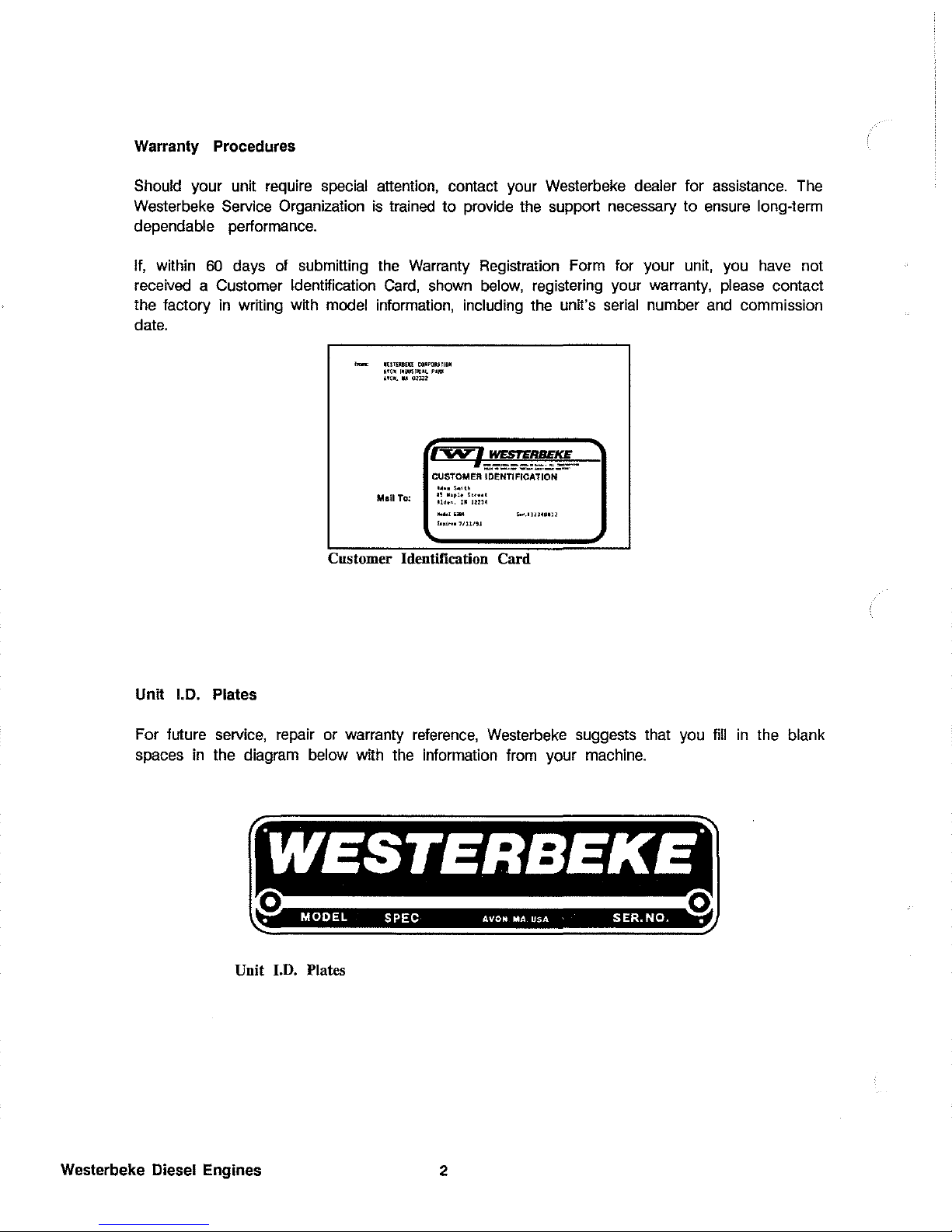
Warranty Procedures
Should your
unit
require special attention, contact your Westerbeke dealer for assistance.
The
Westerbeke Service Organization
is
trained to provide the support necessary to
ensure
long-term
dependable performance.
If,
within
60
days
of
submitting the Warranty Registration Form for your unit, you
have
not
received a Customer
Identification
Card,
shown
below,
registering your warranty,
please
contact
the factory
in
writing with model information, including the unit's
serial
number
and
commission
date.
Unit 1.0. Plates
"""" .["IRBE!.!
COR'ORllI0~
I'O~
1~1M1~IJL
PllII<
uo~
....
ona
'---(~'ff:-
Mall To:
CUSTOMER IDENTIFICATION
••••
~.;.h
II
Mopl. ~ .....
Udo
•.
U 12134
10,,,
..
"llI!1
s..
.•
""._"
Customer Identification
Card
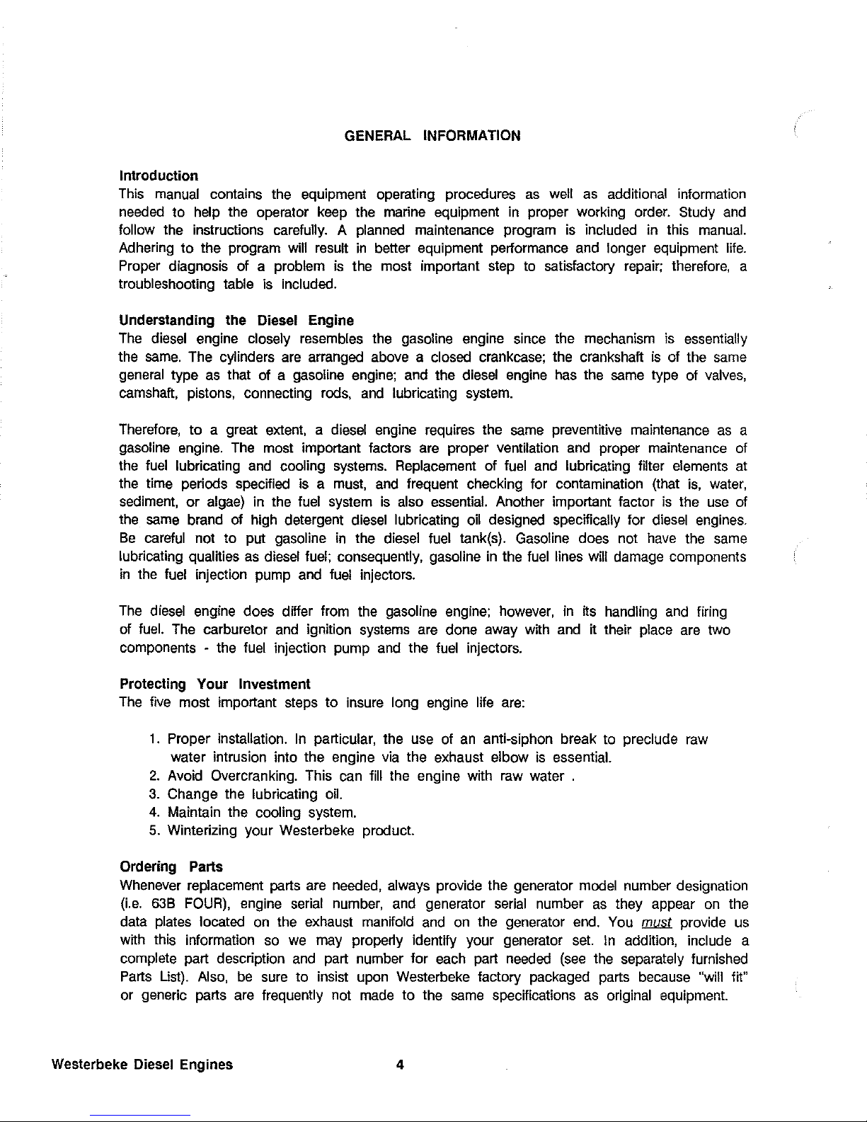
For future service, repair or warranty
reference,
Westerbeke suggests that you
fill
in
the blank
spaces
in
the diagram below with the information from your machine.
-
o 0
•
MODEL
SPEC AVON MA USA
SER.NO..
Unit 1.0. Plates
Westerbeke Diesel Engines
2
Page 9

Section
FOREWORD
GENERAL
INFORMATION
MODEL
PHOTOS
TABLE
OF
CONTENTS
63B
FOUR
GENERAL
SPECIFICATIONS
63B
FOUR
SYSTEM
SPECIFICATIONS
71B
FOUR
GENERAL
SPECIFICATIONS
71B
FOUR
SYSTEM
SPECIFICATIONS
82B
FOUR
GENERAL
SPECIFICATIONS
82B
FOUR
SYSTEM
SPECIFICATIONS
108B
SIX
GENERAL
SPECIFICATIONS
108B SIX
SYSTEM
SPECIFICATIONS
INSTALLATIONS & INSTALLATION
CHECKS
EXHAUST
SYSTEM
RAW
WATER
INTAKE
SYSTEM
OPERATIONS -CAPTAIN'S
PANEL
-
ADMIRAL'S
PANEL
PREPARATIONS
FOR
STARTING
STARTING
PROCEDURE
STOPPING
PROCEDURE
ENGINE
BREAK-IN
PROCEDURES
FUEL
SYSTEM
DC
CONTROL
CIRCUIT
WIRING
DIAGRAM:
#36467
#36844
#39144
COOLING
SYSTEM
LUBRICATION
SYSTEM
TRANSMISSIONS
HBW & HSW -HURTH
BORG
WARNER
WALTER
V-DRIVE
ENGINE
TROUBLESHOOTING
MAINTENANCE & ADJUSTMENTS
LAY-UP & RECOMMISSIONINGIWINTERIZING
TABLE
OF
STANDARD
HARDWARE
TORQUE
SPECIFICATIONS
SPARE
PARTS
Page
1
4
6
14
15
17
18
20
21
23
24
27
34
38
40
42
45
46
49
50
51
56
58
60
62
68
70
70
79
85
90
92
97
100
101
102
Page 10
GENERAL INFORMATION
Introduction
This
manual
contains the equipment operating procedures
as
well
as
additional information
needed
to help the operator
keep
the marine equipment
in
proper working order. Study
and
follow the instructions carefully. A planned maintenance program
is
included
in
this
manual.
Adhering to the program will result
in
better equipment performance
and
longer equipment
life.
Proper diagnosis of a problem
is
the most important step to satisfactory repair; therefore, a
troubleshooting table
is
included.
Understanding the Diesel Engine
The
diesel
engine closely resembles the gasoline engine
since
the mechanism
is
essentially
the
same.
The cylinders
are
arranged
above
a closed crankcase; the crankshaft
is
of the
same
general
type
as
that of a gasoline
engine;
and
the diesel
engine
has
the
same
type of
valves,
camshaft,
pistons, connecting
rods,
and
lubricating
system.
Therefore,
to a great
extent,
a diesel engine requires the
same
preventitive maintenance
as
a
gasoline
engine.
The
most important factors are proper ventilation
and
proper maintenance
of
the
fuel
lubricating
and
cooling
systems.
Replacement of
fuel
and
lubricating filter
elements
at
the time periods specified
is a must,
and
frequent checking for contamination (that
is,
water,
sediment,
or
algae)
in
the
fuel
system
is
also
essential.
Another important factor
is
the
use
of
the
same
brand
of
high detergent diesel lubricating
oil
designed specifically for
diesel
engines.
Be
careful
not to put gasoline
in
the diesel
fuel
tank(s). Gasoline does not
have
the
same
lubricating qualities
as
diesel
fuel;
consequently, gasoline
in
the
fuel
lines will damage components
in
the
fuel
injection pump
and
fuel
injectors.
The
diesel engine does differ from the gasoline
engine;
however,
in
its handling
and
firing
of
fuel.
The
carburetor
and
ignition systems
are
done away with
and
it their place
are
two
components
- the
fuel
injection pump
and
the
fuel
injectors.
Protecting Your Investment
The
five
most important steps to insure long engine
life
are:
1.
Proper installation.
In
particular, the use of
an
anti-siphon break to preclude
raw
water intrusion into the engine
via
the exhaust elbow
is
essential.
2.
Avoid Overcranking. This
can
fill the engine with
raw
water .
3.
Change the lubricating
oil.
4.
Maintain the cooling system.
5.
Winterizing your Westerbeke product.
Ordering Parts
Whenever
replacement parts
are
needed,
always provide the generator model number designation
(Le.
63B
FOUR),
engine
serial
number,
and
generator
serial
number
as
they appear
on
the
data
plates
located
on
the exhaust manifold
and
on
the generator
end.
You
!111.§1.
provide
us
with this information
so
we
may properly identify your generator
set.
In
addition, include a
complete part description
and
part number for
each
part
needed
(see
the separately furnished
Parts
List).
Also,
be
sure
to insist upon Westerbeke factory packaged parts
because
"will fit"
or generic parts
are
frequently not
made
to the
same
specifications
as
original
eqUipment.
Westerbeke Diesel Engines 4
Page 11
General Information (continued)
Note that component locations
in
the
manual
are
referenced
from the front
of
the engine which
is
the pulley/drive belt
end.
(The
flywheel/generator
end
is
the
rear
end.)
Left
and
right
sides
are
deteremined
by
the engine; imagine straddling the engine
and
facing
in
the
same
direciton
as
the front of the engine: the left side
is
at your
left,
the right
side
is
at your
right.
Westerbeke generator
sets
are
thoroughly checked
and
given a
final
run
under various load
conditions before leaving the factory. Test running the generator
ensures
dependable operation,
long service I
ite,
and
a satisfied
owner.
Care at the factory during assembly
and
thorough testing
have
resulted
in
a Westerbeke diesel
engine-driven generator capable of
many
thousands
of
hours of dependable
service.
However,
what the manufacturer cannot
control
is
the manner or location
the
generator
is
installed
in
the
vessel
or the manner
in
which the unit
is
operated
and
serviced
in
the
field.
That
part
is
up to the buyer/owner-operator.
5 Westerbeke Diesel Engines
Page 12

::;;
"
~
ci-
"
~
"
t::l
fi'
i:E.
i":l
'"
.0
s·
"
~
'"
70'
Exhaust
Elbow
Zinc
Anode
Domestic
Water
Heater
(Return)--
__
Instrument
Panel
Connection
___
Transmission
Shift
Lever
Fresh
Water
Coolant
Fill
Optional
DC
Charging
Alternator
Domestic
Water
Heater
Connection
(To)
63
B FOUR
Lube
Oil
Drain
Hose
Adjustable
Engine
Isolator
Page 13

-..j
~
;;
~
?i
\:)
;S"
~
l'l
"
""
S"
il
Optional
Refrigeration
Compressor
\
Top
Engine
Fuel
Injection
Pump
Alarm
Oil
Pressure
Sender
Oil
Fill
Preheat
Solenoid
Lube
Oil
Dipstick
Starter
with
Solenoid
inc
Anode
Domestic
Water
Heater
(Return)
Instrument
Panel
Connection
/
,
Battery
Ground
Connection
Transmission
Cooler
Adjustable
Engine
Isolator
Lube
Oil
Cooler
Transmission
Drain
Page 14

~
t>
~
ci-
t>
,...
'"
~
[
trI
"
'!S.
"
'"
~
00
Domestic
Water
Heater
Connection
Fuel
Manual
Primer
Preheat
Solenoid
________
Zinc
Anode
Domestic
Water
Heater
(Return)-
Heat
Exchanger
Marine
Transmission
(To)
Fresh
Water
Fill
Cap
71 B FOUR
Optional
Refrigeration
Compressor
Optional
DC
Alternator
Page 15

'-0
::::
"
~
;:).
"
~
c
;;.
~
i"j
"
".9.
"
"
~
Optional
Refrigeration
Compressor
Fuel
Lift
Pump
Lube
Oil
Drain
Hose
Oil
Pressu
re
Switch
Lube
Oil
Cooler
Air
Intake
Silencer
Fuel
Manual
Primer
Lube
Oil
Dipstick
/
/
Fuel
Filter
inc
Anode
Domestic
Water
Heater
(Return)
Starter
with
Solenoid
Pressure
Sender
Lube
Oil
Filter
Page 16

~
~
ci-
"
?:
I:;
[
M
::l
OQ
S·
~
-
o
Exchanger
Air
Bleed
Petcock
70°
Exhaust
Elb
Domestic
Water
Heater
(Return)
Instrument
Panel
Connection
Transmission
Shift
Lever
Domestic
Water
Fresh
Water
Unit
I.
D.
Plate
DC
Charging
Alternator
Raw
Water
Pump
Lube
Oil
Drain
Hose
(To)
Adjustable
Engine
Isolator
Starter
with
Solenoid
82
B FOUR
Page 17

-
-
~
~
"
d-
"
:r.-
"
l:'
;;0
~
t'l
=
1J,S.
=
&l
Fuel
Lift
Pump
Fuel
Injection
Pump
Top
Engine
Oil
Fill
Adjustable
Engine
Isolator
f
Oil
Pressure
Sender
Preheat
Solenoid
Lube
Oil
Filter
Secondary
Fuel
Filter
Zinc
Anode
Domestic
Water
Heater
(Return)
Fresh
Water
Block
Drain
Plug
Transmission
Cooler
Transmission
Drain
• F
Page 18

~
~
do
"
~
o
[
l'1
"
..
5"
I;;
-
IV
Domestic
Water
Heater
(To)
90'
Exhaust
Elbow
Exchanger
Air
Bleed
Petcock
Transmission
Cooler
Transmission
Dipstick
Transmission
Vent
Transmission
Drain
Plug
Fresh
Water
Fill
Cap
Starter
with
Solenoid
108 B
SIX
Top
Engine
Oil
Fill
Cap
Lu
DC
Charging
Alternator
Oil
Drain
Hose
Page 19

~
w
::::;
~
'"
;:).
'"
:>:'
"
I:;)
;;.
~
1'1
"
".9.
1:
'"
Top
Engine
Oil
Fill
Cap
Water
Temperature
Alarm
Switch
Water
Temperature
Sender
Fresh
Water
Circulating
Pump
Adjustable
Engine
Isolator
Lube
Oil
r
Secondary
Fuel
Filter
Oil
Pressure
Sender
Fuel
Lift
Pump
20
A
DC
Circuit
Breaker
Zinc
Anode
Domestic
Water
Heater
(Return)
Instrument
Panel
Connection
il
Pressure
Alarm
Switch
Page 20

63(B) & (C)
Four
Marine
Diesel
Engine
General
Specifications
Engine Type
Governor
Valve Mechanism
Combustion Chamber
Bore
& Stroke
Piston Displacement
Firing
Order
Direction
of
Rotation
Maximum Torque (at
2900 rpm)
Compression Ratio
Compression
Pressure
Valve Seat Angle
Valve Clearance
(engine cold)
Dimensions
Inclination
Dry Weight
Engine
Speed
Fuel Consumption
Westerbeke Diesel Engines
Diesel, four-cycle, fresh water-cooled, vertical, in-line
(63
hp at 3600 rpm maximum)
Integral
of
the injection pump, mechanical flyweight type.
Overhead
Swirl chamber type
3.50 x 3.51 inches (88.9 x 89.9 mm)
134.8 cubic inches (2.21 liters)
1-3-4-2
Clockwise, when viewed from the front
93
Ib-ft (10.92 kg-m)
21:1
427 psi
(30.0 kg/cm') at 200 rpm
Intake
45° Exhaust 45°
Intake 0.12 inches (OJ mm)
Exhaust
0.012 inches (0.3 mm)
Height: 25.30 inches (642.6 mm)
Width: 21.19 inches (538.2 mm)
Length: 38.75 inches (984.3 mm)
Continuous
14° Temporary 25° (not to exceed 30 min.)
611
lbs
(192 kgs)
Idle speed:
750 - 1000 rpm
Cruising speed:
2500 - 3000 rpm
1.2
US
gph (4.5 Iph) running
at
2500 rpm (approximate)
when the propeller allows 3600 rpm at full open throttle
while underway
in
forward gear.
14
Page 21

63(B) & (C)
Four
Marine
Diesel Engine
General
Specifications
(Continued)
Fuel
System
Fuel
Injection
Pump
Injection Timing
Nozzle
Injection
Pressure
LiftPump
Fuel Filter (on engine)
Air Cleaner
Air Flow (engine combustion)
(engine cooling)
Cooling
System
General
Operating Temperature
Fresh Water
Pump
Sea
Water Pump
No.2
diesel oil (cetane rating
of
45
or higher)
Diesel KIKI Mechanical Governed
OOTDC
Throttle type
1920 psi (135 kg/cm
2
)
12
volt plunger type
Spin-on (replaceable)
Metal screen type-cleaner
140 cfm (3.9 cmm) at 3600 rpm
250 cfm (7.0 cmm)
Fresh water-cooled block, thermostatically-controlled
with
sea water exchanger system.
170 -
1900 F (77 - 88
0
C)
Centrifugal type, metal impeller, belt-driven
Positive displacement, rubber impeller, gear-driven
Sea Water Flow,
at
3600 rpm 12.0 gpm (45.4 Ipm) approximate
(measured before discharging into
exhaust elbow)
System Capacity (fresh water)
Lubrication
System
General
Oil Filter
Sump Capacity
Operating
Oil Pressure
Oil
Grade
10
U.S. qts. (9.9 liters)
Pressure feed, rotor type, driven
by
spiral gears from
camshaft
Full flow, paper element, spin-on type
5.3
U.S. qts. (5.0 liters) not including filter
30 - 60 psi (2.1 - 4.2
kg/cnl)
at maximum engine rpm and
at normal operating temperature.
API specification CC or
CD
15
Westerbeke Diesel Engines
Page 22
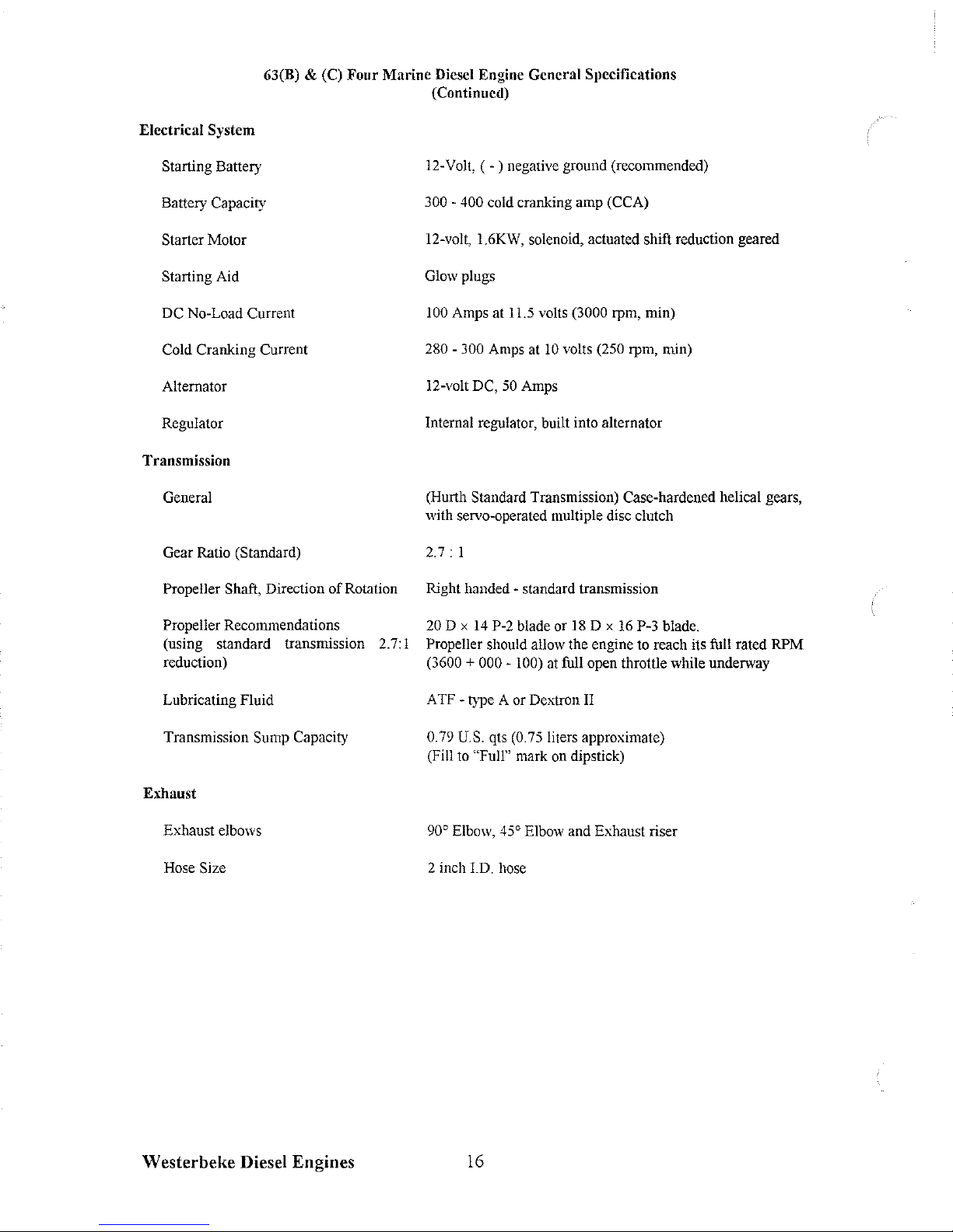
63(B) & (C) Four Marine Diesel Engine General Specifications
(Continued)
Electrical
System
Starting Battery
Battery Capacity
Starter Motor
Starting Aid
DC No-Load Current
Cold Cranking Current
Alternator
Regulator
Transmission
General
Gear Ratio
(Standard)
Propeller Shaft,
Direction
of
Rotation
Propeller Recommendations
(using standard transmission 2.7:1
reduction)
Lubricating Fluid
Transmission
Sump Capacity
Exhaust
Exhaust elbows
Hose
Size
Westerbeke Diesel Engines
12-
Volt, ( - ) negative ground (recommended)
300 - 400 cold cranking amp (CCA)
12-volt, 1.6KW, solenoid, actuated shift reduction geared
Glow plugs
100
Amps at
U.S
volts (3000 rpm, min)
280 - 300 Amps at
10
volts (250 rpm, min)
12-volt DC,
50
Amps
Internal regulator, built into alternator
(Hurth
Standard Transmission) Case-hardened helical gears,
with servo-operated multiple disc clutch
2.7:
I
Right handed - standard transmission
20 D x
14
P-2 blade or
18
D x
16
P-3 blade.
Propeller should allow the engine to reach its full rated RPM
(3600
+ 000 - 100) at full open throttle while underway
A TF - type A or
DeA1ron
II
0.79
U.S. qts (0.75 liters approximate)
(Fill to
"Full" mark on dipstick)
90'
Elbow,
45'
Elbow and Exhaust riser
2 inch I.D. hose
16
Page 23

71
B Four Marine Diesel Engine General Specifications
Engine Type
Governor
Valve
Mechanism
Combustion Chamber
Bore &
Stroke
Piston Displacement
Firing Order
Direction of Rotation
Maximum Torque
(at
2200
rpm)
Compression
Ratio
Compression
Pressure
Valve
Seat
Angle
Valve
Clearance
(engine cold)
Dimensions
Inclination
Dry Weight
Engine
Speed
Fuel
Consumption
Westerbeke
Diesel Engines
Diesel,
four-cycle, four-cylinder, fresh water-cooled,
vertical,
in-line
(71
hp at
3600
rpm
maximum)
Intergral
of
the injection pump, mechanical
flyweight type
Overhead
Swirl
chamber type
3.50 x 4.0
inches
(88.9 x 101.6
mm)
154.0
cubic inches
(2.5
liters)
1-3-4-2
Clockwise, when
viewed
from the front
118
Ib-ft
(16.31
kg-m)
21:1
427
psi
(30
kgJcm
2
)
at
200
rpm
Intake 45', Exhaust 30'
Intake
0.012
inches
(0.3
mm)
Exhaust
0.012
inches
(0.3
mm)
Height:
26.9
inches
(684.2
mm)
Width:
22.2
inches
(563.6
mm)
Length:
39.5
inches
(1003.3
mm)
Continuous 14', Temporary 25'
(not to
exceed
30
min.)
652
Ibs
(295.9
kgs)
Idle
speed:
750 -1000
rpm
Cruising
speed:
2500 -3000
rpm
1.4
U.S.
gph
(5.2
Iph)
running at
2500
rpm
(approximate) when the propeller allows
3600
rpm
at
full
open throttle while underway
in
forward
gear.
17
Page 24

718 Four Marine Diesel Engine System Specifications
Fuel System
Fuel
Injection Pump
Injection Timing
Injectors
Injection
Pressure
Lift Pump
Fuel
Filter
(on
engine)
Air
Cleaner
Air Flow (engine combustion)
Cooling System
General
Operating Temperature
Fresh
Water Pump
Sea
Water Pump
Sea
Water
Flow,
at
3600
rpm
(measured before discharging
into exhaust
elbow)
System
Capacity (fresh water)
Lubrication
System
General
Oil
Filter
Sump Capacity
Operating
Oil
Pressure
No.
2 diesel
oil
(cetane rating of
45
or
higher)
Diesel
KiKi
mechanical governed
0°
TOC
Throttle type
1920
psi
(135
kg/cm
2
)
12
volt - plunger type
Spin-on type (replaceable)
Metal
screen type - cleanable
160.4
cfm
(4.5
cmm) at
3600
rpm
Fresh
water cooled block, thermostatically-controlled
with
sea
water exchanger system
170 -190° F (77 -88°
C)
Centrifugal type,
metal
impeller, belt-driven
Positive displacement, rubber impeller, gear-driven
10
gpm
(37.8
Ipm)
approximate
11.5
U.S.
qts
(10.9
liters)
Pressure
feed,
rotor type, driven
by
sprial gears
from camshaft
Full
flow, paper element, spin-on type
6.3
U.S.
qts
(6.0
liters) not including filter
30 -60
psi
(2.1 -4.2
kg/cm
2
)
at maixmum engine
rpm
and at normal operating temperature
Oil
Grade
API
specification
CC
or
CD
18
Westerbeke Diesel Engines
Page 25
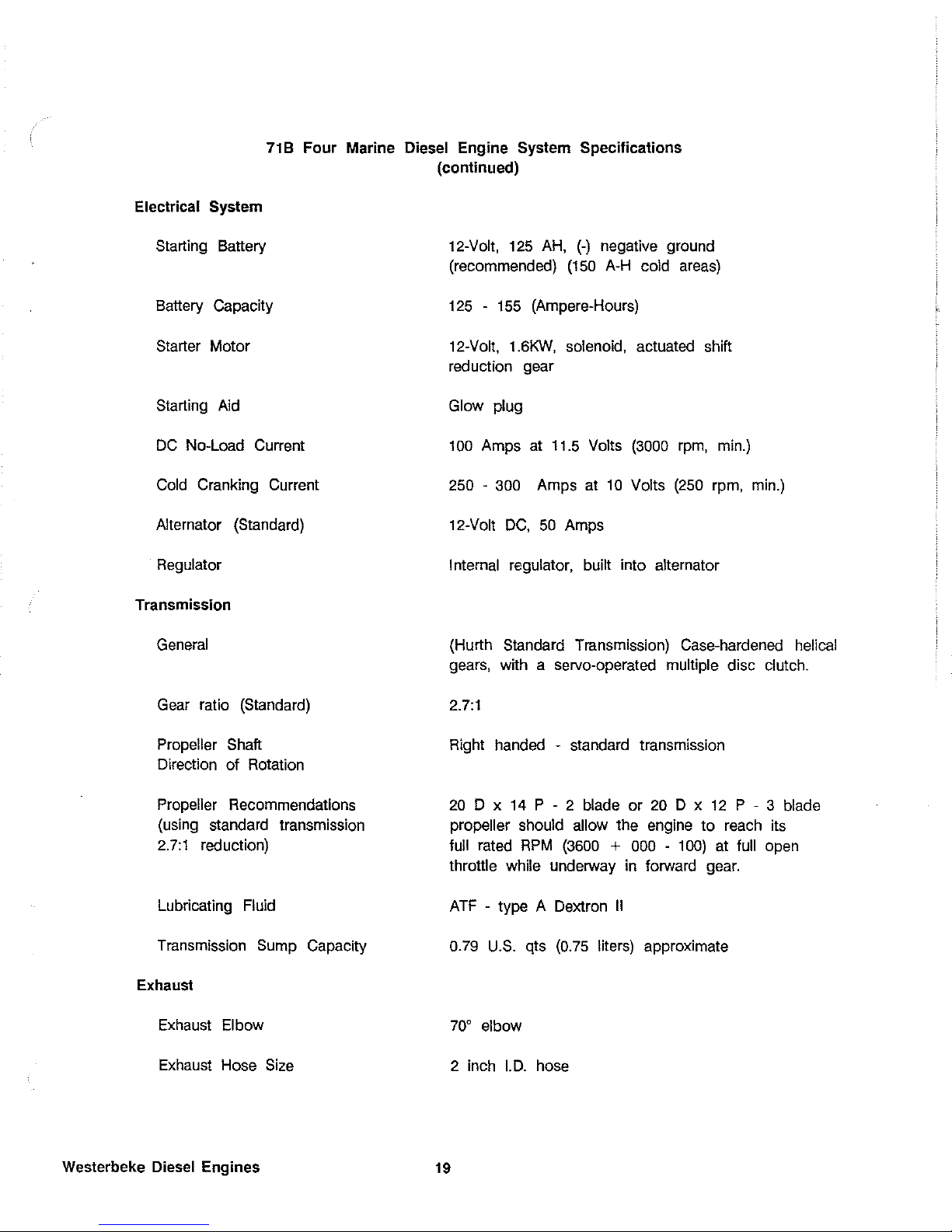
71
B Four Marine Diesel Engine System Specifications
(continued)
Electrical System
Starting
Battery
Battery Capacity
Starter Motor
Starting
Aid
DC
No-Load Current
Cold
Cranking Current
Alternator (Standard)
Regulator
Transmission
General
Gear
ratio (Standard)
Propeller Shaft
Direction of Rotation
Propeller Recommendations
(using
standard transmission
2.7:1
reduction)
Lubricating
Fluid
Transmission
Sump
Capacity
Exhaust
Exhaust
EI
bow
Exhaust
Hose
Size
Westerbeke Diesel Engines
12-Volt,
125
AH,
(-)
negative ground
(recommended)
(150
A-H
cold
areas)
125 -155
(Ampere-Hours)
12-Volt,
1.6KW,
solenoid, actuated shift
red
uction gear
Glow plug
100
Amps at
11.5
Volts
(3000
rpm,
min.)
250 -300
Amps at
10
Volts
(250
rpm,
min.)
12-Volt
DC,
50
Amps
I nternal regulator, built into alternator
(Hurth Standard Transmission) Case-hardened helical
gears, with a servo-operated multiple disc clutch.
2.7:1
Right handed - standard transmission
20
D x
14
P - 2 blade or
20
D x
12
P - 3 blade
propeller should allow
the engine to
reach
its
full rated
RPM
(3600 + 000 -100)
at
full
open
throttle while underway
in
forward
gear.
A
TF
- type A Dextron
II
0.79
U.S.
qts
(0.75
liters) approximate
70' elbow
2 inch
I.
D.
hose
19
Page 26
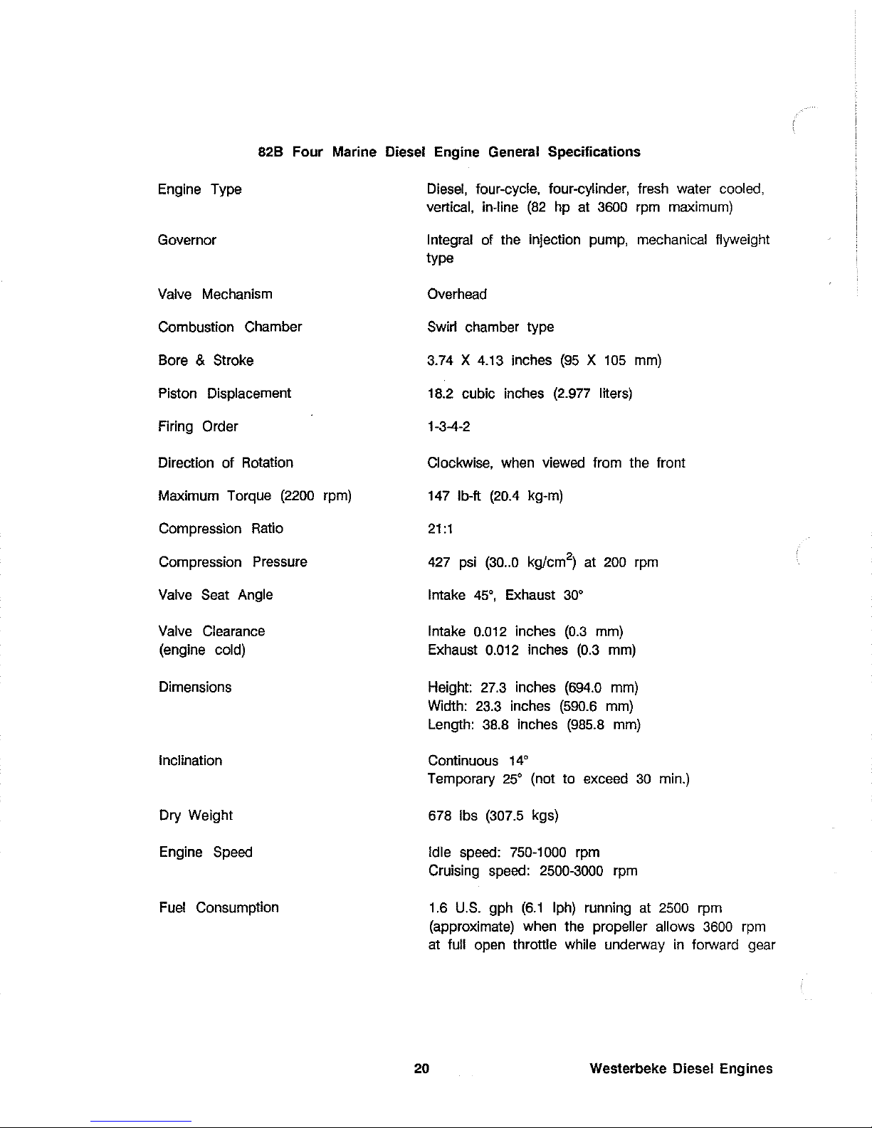
82B
Four Marine
Diesel
Engine
General
Specifications
Engine Type
Governor
Valve
Mechanism
Combustion Chamber
Bore
& Stroke
Piston Displacement
Firing
Order
Direction of Rotation
Maximum Torque
(2200
rpm)
Compression
Ratio
Compression Pressure
Valve
Seat
Angle
Valve
Clearance
(engine cold)
Dimensions
Inclination
Diesel,
four-cycle, four-cylinder, fresh water cooled,
vertical, in-line
(82
hp at
3600
rpm
maximum)
Integral
of
the injection pump, mechanical flyweight
type
Overhead
Swirl chamber type
3.74 X 4.13
inches
(95 X 105
mm)
18.2
cubic inches
(2.977
liters)
1-3-4-2
Clockwise,
when
viewed
from the front
147
Ib-ft
(20.4
kg-m)
21
:1
427
psi
(30
..
0 kglcm
2
)
at
200
rpm
Intake 45', Exhaust 30'
Intake
0.012
inches
(0.3
mm)
Exhaust
0.012
inches
(0.3
mm)
Height:
27.3
inches
(694.0
mm)
Width:
23.3
inches
(590.6
mm)
Length:
38.8
inches
(985.8
mm)
Continuous 14'
Temporary 25' (not to exceed
30
min.)
Dry Weight 678
Ibs
(307.5
kgs)
Engine
Speed
Idle
speed:
750-1000
rpm
Cruising
speed:
2500-3000
rpm
Fuel
Consumption
1.6
U.S.
gph
(6.1
Iph)
running at
2500
rpm
(approximate) when the propeller allows
3600
rpm
at
full
open
throttle while underway
in
forward gear
20
Westerbeke
Diesel Engines
Page 27

82B Four Marine Diesel Engine System Specifications
FUEL SYSTEM
Fuel
Injeciton Pump
Injection Timing
ilnjectors
Injection Pressure
Lift Pump
Fuel
Filter (on engine)
Air Cleaner
Air Flow (engine combustion)
(engine cooling)
COOLING SYSTEM
General
Operating Temperature
Fresh Water Pump
Sea
Water Pump
Sea
Water Flow, at
3600
rpm
(measured before discharging
into exhaust elbow)
System Capacity (fresh water)
LUBRICATING SYSTEM
General
Oil
Filter
Sump Capacity
Westerbeke Diesel Engines
No. 2 diesel
oil
(cetane rating of
45
or higher)
Diesel
Kiki
0"
TDC
(Static Timing)
Throttle
1920
psi
(135
kg/cm
2
)
12
Volt plunger tyupe
Spin-on (replaceable)
Metal
screen type - cleanable
189.5
cfm
(5.3
cmm) at
3600
rpm
250 cfm
(7.0
cmm)
Fresh
water-cooled block,
Thermostatically-controlled
with
sea
water exchanger system
170-190" F
(77-88"
C)
Centrifugal type, metal impeller, belt-driven
Positive displacement, rubber impeller, belt-driven
14
gpm
(53
Ipm)
approximate
21
13
U.S.
qts
(12.3
liters)
Pressure
feed,
rotor type, driven by sprial gears from
camshaft
Full
flow, paper element, spin-on type
6.3
U.S.
qts
(6.0
liters) not including filter
Page 28

82B Four Marine Diesel Engine System Specifications
(continued)
Operating
Oil Pressure
Oil Grade
ELECTRICAL SYSTEM
Starting
Battery
Battery Capacity
Starting Aid
Starter Motor
DC
No-Load Current
Cold Cranking Current
Alternator
(Standard)
Regulator
TRANSMISSION
General
Gear Ratio (Standard)
Propeller Shaft
Propeller
Recommendations
(using strandard Transmission
2.0:1
reduction)
Lubricating
Fluid
Transmission Sump Capacity
EXHAUST
Exhaust Elbow
Exhaust Hose Size
30-60
psi (2.1-4.2 kg/cm
2
)
at maximum engine
rpm
and at normal operating temperature
API
Specification
CC
or
CD
12-Volt,
125
A-H,
(-)
negative ground (recommended)
(150
A-H
cold areas)
125-155 (Ampere-Hours)
Glow plugs
12-Volt,
3.0KW,
solenoid, actuated shift, reduction gear
100
Amps at
11.5
volts
(3000
rpm, min.)
250-300 Amps at
10
Volts
(250
rpm, min.)
12-Volt
DC,
51
Amps
Internal regulator, mounted on alternator
(Hurth Standard Transmission) Case-hardened helical
gears, with servo-operated multiple disc clutch
2.04:1
Right handed - standard transmission
20
D X
12
P-2
blade or
20
D X
10
P-3
blade
propeller should allow
the engine to reach its full
rated
RPM
(3600 + 000
- 100) at full open throttle
while underway
in
forward gear
ATF-type A or Dextron
II
0.79
U.S.
qts
(0.75
liters) approximate
700 elbow
2 inch
I.D.
hose
22
Westerbeke
Diesel Engines
Page 29
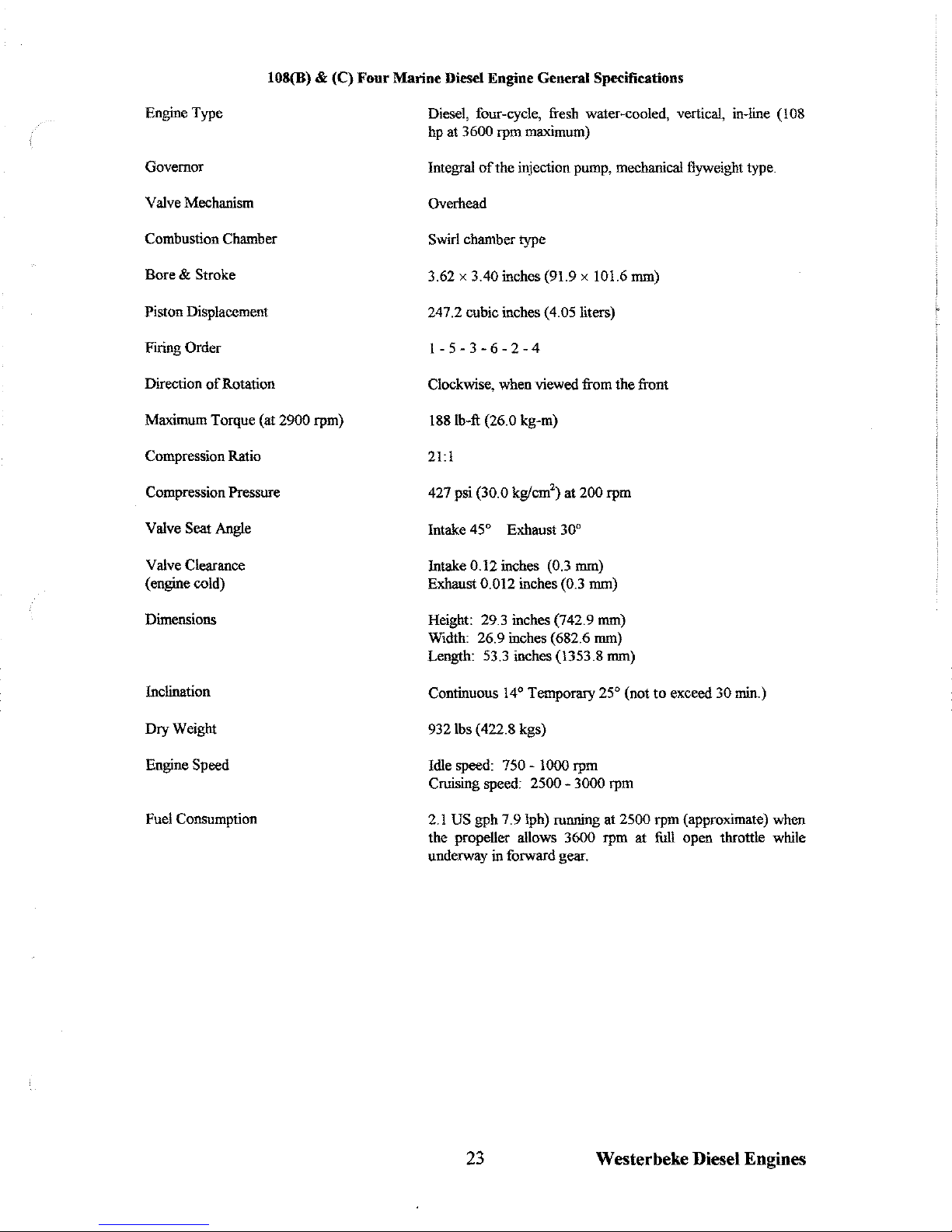
l08(B)
& (C) Four Marine Diesel Engine General Specifications
Engine Type
Governor
Valve Mechanism
Combustion Chamber
Bore
& Stroke
Piston Displacement
Firing Order
Direction
of
Rotation
Maximum Torque (at
2900 rpm)
Compression Ratio
Compression Pressure
Valve Seat Angle
Valve Clearance
(engine cold)
Dimensions
Inclination
Dry Weight
Engine Speed
Fuel Consumption
Diesel, four-cycle, fresh water-cooled, vertical, in-line
(108
hp at 3600 rpm maximum)
Integral
of
the injection pump, mechanical flyweight type.
Overhead
S~rlchambertype
3.62 x 3.40 inches (91.9 x 101.6 mm)
247.2 cubic inches (4.05 liters)
1-5-3-6-2-4
C1oc~se,
when viewed from the front
1881b-ft
(26.0 kg-m)
21:1
427 psi (30.0 kg/em') at 200 rpm
Intake
45° Exhaust 30°
Intake 0.12 inches (0.3 mm)
Exhaust
0.012 inches (0.3 mm)
Height: 29.3 inches (742.9 mm)
Width: 26.9 inches (682.6 mm)
Length: 53.3 inches (1353.8 mm)
Continuous
14° Temporary 25° (not
to
exceed 30 min.)
9321bs (422.8 kgs)
Idle speed:
750 - 1000 rpm
Cruising speed:
2500 - 3000 rpm
2.1
US
gph
7.91ph) running at 2500 rpm (approximate) when
the propeller allows
3600 rpm at full open throttle while
underway
in forward gear.
23
Westerbeke Diesel Engines
Page 30

l08(B)
& (C)
Four
Marine
Diesel Engine General Specifications
(Continued)
Fuel
System
Fuel
Injection Pump
Injection Timing
Nozzle
Injection Pressure
Lift Pump
Fuel Filter (on engine)
Air Cleaner
Air Flow (engine combustion)
(engine cooling)
Cooling
System
General
Operating Temperature
Fresh Water Pump
Sea Water Pump
No.2
diesel oil (cetane rating
of
45
or higher)
Diesel KIKI Mechanical Governed
oomc
Throttle type
1920 psi (135 kg/cm')
12
volt plunger type
Spin-on (replaceable)
Metal screen type-cleaner
257 cfm (7.9 cmm) at 3600 rpm
250 cfm (7.0 cmm)
Fresh water-cooled block, thermostatically-controlled with
sea water exchanger system.
170
- 190° F (77 - 88° C)
Centrifugal type, metal impeller, belt-driven
Positive displacement, rubber impeller, gear-driven
Sea Water Flow, at 3600 rpm 14.0 gpm
(53
lpm) approximate
(measured before discharging into
exhaust elbow)
System Capacity (fresh water)
Lubrication
System
General
Oil Filter
Sump Capacity
Operating
Oil Pressure
Oil Grade
Westerbeke Diesel Engines
16
U.S. qts. (15.1 liters)
Pressure feed, rotor type, driven
by
spiral gears from
camshaft
Full flow, paper element, spin-on type
11.9
U.S. qts. (11.3 liters) not including filter
30 - 60 psi
(2.1
- 4.2 (135 kg/cm') at maximum engine rpm
and at normal operating temperature.
API specification
CC
or
CD
24
Page 31
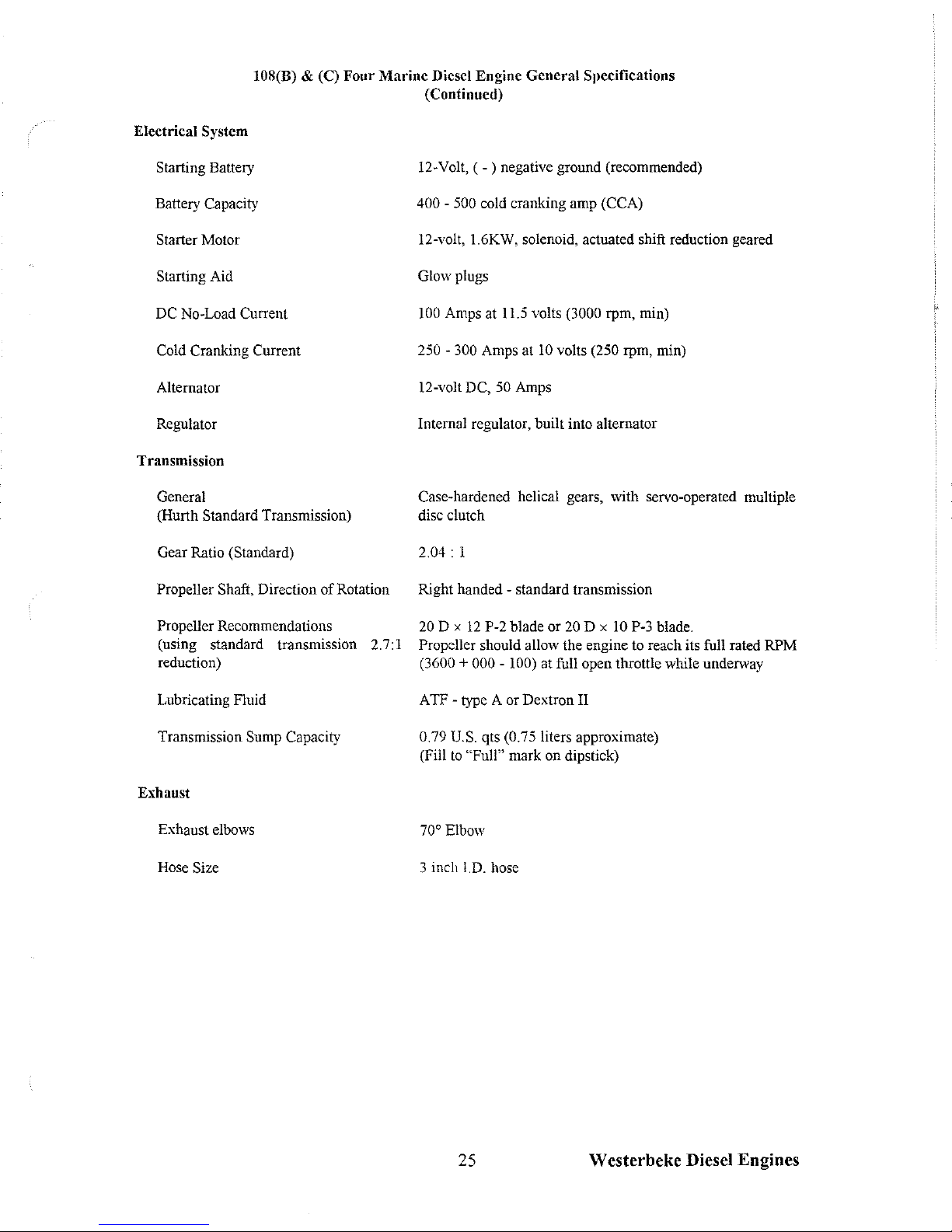
l08(B) & (C)
Four
Marine
Diesel Engine
General
Specifications
(Continued)
Electrical
System
Starting
Battery
Battery Capacity
Starter Motor
Starting Aid
DC No-Load Current
Cold Cranking Current
Alternator
Regulator
Transmission
General
(Hurth
Standard Transmission)
Gear Ratio
(Standard)
Propeller Shaft,
Direction
of
Rotation
Propeller Recommendations
(using standard transmission 2.7:1
reduction)
Lubricating Fluid
Transmission
Sump Capacity
Exhaust
Exhaust elbows
Hose
Size
12-
Volt, ( - ) negative ground (recommended)
400 - 500 cold cranking amp (CCA)
12-volt, 1.6KW, solenoid, actuated shift reduction geared
Glow plugs
100 Amps at
11.5 volts (3000 rpm, min)
250
- 300 Amps at
10
volts (250 rpm, min)
12-volt DC,
50 Amps
Internal regulator, built into alternator
Case-hardened helical gears, with servo-operated multiple
disc clutch
2.04:
I
Right handed
- standard transmission
20 D x
12
P-2 blade or
20
D x 10 P-3 blade.
Propeller should allow the engine to reach its full rated RPM
(3600 + 000 - 100) at full open throttle while underway
A
TF
- type A or Dextron II
0.79
U.S. qts (0.75 liters approximate)
(Fill
to
"Full" mark on dipstick)
70'
Elbow
3 inch
I.D.
hose
25 Westerbeke Diesel Engines
Page 32

NOTES
26
Westerbeke Diesel Engines
Page 33
INSTALLATIONS and INSTALLATION CHECKS
General
Since the boats
in
which Westerbeke engines
are
installed vary
in
design, installation procedures
will vary according to your craft's specific design.
The
intent
of
this section
is
not to advise
boatyards or installers on procedures already well-developed
and
well-understood. However, the
owner/operator must
realize
there
are
details
of
the installation which require periodic checks
to ensure the best operating
condITions
for the equipment
and
safe operating conditions for
the personnel on board. Proper location
and
installation of the diesel engine
in
the
vessel
are
of prime importance.
Factors
in
the installation that must
be
considered
are;
(1)
ventilation, to
aid
in
cooling
and
to
provide air for engine combustion,
(2)
the
exhaust
system,
to properly discharge
raw
cooling
water, to guiet the exhaust
and
to
expel
exhaust
gas,
(3)
the cooling water supply,
(4)
the
fuel supply,
(5)
the electrical connections
and
(6)
the
transmission/propeller connections.
I
CAUTIoN
I
For safety
reasons,
the engine
is
not filled with lubricating
oil
for shipment. Before leav-
ing the factory, however,
each
engine
and
transmission
is
thoroughly tested with oil.
This
testing, among other things, provides
all
internal
parts
with a coating
of
oil.
This
oil
acts
as
a preservative, providing reliable protection against corrosion for at least one year
if
the engine
and
transmission
is
properly stored.
Inspection
of
Equipment
The
engine
is
shipped from the factory securely mounted
and
properly crated. Accessory
equipment
is
shipped
in
a separate
small
box,
usually packed within the engine's crate.
Before accepting shipment
of
the
engine from the transportation company, the crate should
be
opened and
the
contents inspected for concealed
damage.
If
eITher
visible or concealed damage
is
noted, you should require
the
delivery agent
sign
"Received
in
damaged
condITion"
on
the
proper delivery receipt. Also check
the
contents
of
the
shipment against the packing list and
make
sure that the proper notation
is
made
if
any
discrepancies exist.
These
noted discrepancies
are
your protection against loss or
damage.
Claims concerning loss or damage must
be
made
to the
carrier, not to Westerbeke Corporation.
Please
note that the engine's installation angle cannot exceed
14'
from the horiziontal
plane.
Rigging and Lifting
The
engine
is
fitted with lifting
eyes.
Rope
or chain slings capable of supporting the engine's
weight should
be
attached to
the
eyes
and
the engine lifted by means of tackle attached
to
these slings.
The
lifting
eyes
have
been
designed
to
carry the
full
weight of the engine; therefore,
auxiliary
slings
are
not required or desired.
Westerbeke Diesel Engines
27
Page 34

!CAUTION
I
Slings must not
be
so
short
as
to place significant stress on the engine's
lifting
eyes.
Strain placed
on
the engine's lifting
eyes
by
the lifting sling
must not
be
in
excess of
10'
from the vertical
plane.
The
general
rule
in
moving engines
is
to
see
that
all
equipment
used
is
amply strong
and
firmly fixed in
place.
Move
the engine a little at a time
and
see
that it
is
firmly supported.
Eliminate the possibility of accidents by avoiding
haste.
Do not lift the engine by
its
crankshaft
pulley.
In
certain situations
it
may
be
necessary to lift the engine
in
positions other than the horizontal
position. Certain situations exist by which the engine must be lowered endwise through a
small
hatchway which cannot be made larger.
Under these conditions,
if the opening
of
the hatchway
is
extremely
small,
it
is
possible
to reduce,
to
some
extent,
the outside dimen-
10'
sions
of
the engine by removing
external
components such
as
the cooling system's
piping, the heat exchanger, certain filters,
the mounting rails
and
other obstructive
equipment. This
accessory
equipment
should
be
removed
by a competent
mechanic and special care should
be
taken
to avoid damage to any exposed parts.
In
addition, be careful not
to
allow dirt to enter
any
opening created by the
removal
of
equipment. Removed parts should be
returned
to
their respective position once
the engine
is
in
its installation
area.
Replace
gaskets
as
needed for the parts that
were
removed.
ENGINE
SLING
LIFT
ING
ANGLE
MUST
NOT
EXCEED
10'
LIFTING
EYE
In
case
it
becomes necessary to hoist
the
engine front-end upwards or transmission-end upwards,
the attachment
of
lifting slings must
be
done carefullv to avoid the possibility of damaging
the
parts
on
which the weight of the slings
may
bear.
Special rigging work
is
best done
by
someone
experienced
and
competent
in
handling
heavy
machinery.
Engine
Bolts
Bronze or stainless
steel
hanger bolts of appropriate size
are
recommended for
use
through
the engine's flexible mounts.
Less
preferred
are
lag screws because their hold on the wood
is
weakened every time they
are
moved, whereas the hanger bolts stay
in
position.
If
the
nut
on
top
of
the hanger bolt
is
removed to allow the engine to
be
lifted from
its
resting place, the
hanger
bolt itself
remains
in
place
as a stud.
Consequently, the bond between the hanger bolt
and
the wood or fiberglass
is
not
weakened
by the removal of the nut or the engine.
28 Westerbeke Diesel Engines
Page 35

Foundation for the Engine
A good engine
bed
contributes much toward the satisfactory operation
of
the
engine.
The
engine's
bed
must
be
rigidly constructed
and
neither deflect nor twist when
it
is
subjected to
the engine's weight or to the pressures that the boat may experience while operating
in
rough
seas.
The
bed
must keep the engine's alignment within one or two thousandths
of
an
inch
of
this position at
all
times.
The
bed
has
to withstand the forward
push
of
the
propeller
shaft
which pushes against the thrust washer bearing which finally pushes against the engine's bolts
and
bed.
In
fiberglass
hulls,
we
recommend that similar
wooden stringers
as
in
wooden hulls
be
formed
and
fitted, then glassed securely to
the
hull.
This
allows the hanger bolts to
be
installed firmly
in
the wood, thereby reducing
noise
and
transmitted vibration.
The
engine support stringers
must
be
as
wide or wider than the engine mounting
isolator.
Isolator overhang and/or rounded
stringer surfaces are detrimental to the
isolators' ability
to
retain vibration.
Preformed fiberglass engine
beds,
when
used,
should
be
of
sufficient thickness to properly
support the engine and should
be
well-
glassed
to the hull when installed.
GOOD
A
BAD
B
Avoid excessive height,
use
solid
The
temptation to install the engine
on
a pair stringer construction
(A).
of fiberglass angle irons must
be
resisted.
Such
construction will allow engine vibration
to
pass
through to
the
hUll.
Flexible mounts
require a firm foundation against which they must act
if
they
are
to
perform their function.
When
possible, follow
bed
design A
and
avoid
bed
design B (refer
to
the illustration).
Supports
between
the
bed
stringers, and extending from the stringers to the
hull,
may
be
required for proper support
and
to
aid
in
the absorption
of
vibrations.
Propeller Shaft Coupling
The
propeller shaft coupling fitted to the transmission's output flange must transmit not only
the
power of the engine
to
turn
the
propeller shaft and propeller, but must also transmit
the
thrust
of
the engine/transmission either
ahead
or astern.
The
coupling should be carefully machined for a slight forced fit onto the shaft
and
an
accurate
mating surface for
the
coupling to the output flange of the transmission.
For
all
engine models, a propeller half-coupling, bored to shaft
size
for the specific order,
is
supplied.
The
coupling either
has
a keyway with
set
screws or
is
of the clamping type.
29
Westerbeke Diesel Engines
Page 36

The
forward
end
of the propeller shaft
has
a long straight
keyway.
Any burrs should
be
removed
from the shaft's
end.
The
coupling should
be
a light drive fit
on
the shaft
and
the shaft should
not
have
to
be scraped down or filed
in
order
to
get a
fit.
It
is
important that the
key
be
properly fitted both
to
the shaft
and
to
the coupling.
The
key
should
Itt
the side of the keyway
closely, but should not touch the top of the keyway
in
the
hub of the coupling.
If
driving the coupling over the shaft
is
difficult,
the
coupling
can
be
expanded by heating it
in a pail
of boiling
water.
The face
of
the propeller coupling must
be
exactly perpendicular to
the centerline or axis of the
propeller shaft.
Propeller
The
type and
size
of propeller varies with the gear ratio
and
must
be
selected to fit the
application, based upon boat tests. To utilize the
full
power
of
the
engine,
and
to achieve ideal
loading conditions,
use
a propeller which will permit the engine to
reach
its
full
rated
RPM
at
full
throttle while under a normal load and while
it
is
moving the boat forward through the
water.
Alignment
of
the Engine
The
engine must be exactly aligned with the propeller shaft
in
the proper fashion. No matter
what material
is
used
to build a boat the material will
be
found to
be
flexible to some extent;
hence,
the boat's hull will change
its
shape to a greater extent than
is
usually realized when
the boat
is
launched
and
operated
in
the
water.
Therefore, it becomes extremely important to
check the engine's
alignment at frequent intervals and to correct any errors
when
they appear.
Misalignment between the engine
and
the propeller shaft often creates serious problems which
are
often blamed on other areas suspected
of
causing
the
trouble. Misalignment will
cause
excessive bearing
wear,
rapid shaft wear and
will,
in
many
cases,
reduce the life of the boat's
hull
by loosening the hull's fastenings. A bent propeller
shaft
will
have
the exact effect
as
those
just stated; therefore, a perfectly straight
propeller shaft
is
absolutely necessary. One particularly
annoying result of
misalignment
may
be
leakage of transmission
oil
through the transmission's
rear
oil
seal.
If
oil
is
leaking from this
seal,
check
and
make
sure
that the alignment
is
within
the limits prescribed below.
Never attempt a final
alignment with the boat on land.
The
boat should
be
in
the water and
have
had
an opportunity to assume
its
final water form.
The
best time to perform the propeller
shaft/transmission coupling alignment
is
with the
fuel
and
water tanks about half
full
and
all
the
usual
equipment on board,
and
after the
main
mast
has
been
stepped
and
the final rigging
has
been
accomplished.
Take
plenty of time
in
making this alignment
and
do not
be
satisfied with anything less than
perfect results.
Westerbeke Diesel Engines
30
Page 37

The
alignment
is
correct when
the
shaft
can
be
easily slipped backward and forward into
the counterbore,
and
when
a
feeler
gauge
indicates that the flanges come together at
all
points.
The
alignment between the propeller
shaft
coupling
and
the engine's coupling
can
contain
an
error no greater than one thousandth
of
an
inch per inch of the coupling diameter.
For
example,
"\
.993
FEELER
GAGE
"
PROPELLER
\
""
h
~
l
.......
-'
ISTRAIGHT
EOGEI
if your propeller shaft coupling
is
three inches
in
diameter, the maximum error that
can
be
allowed
in
the alignment
is
three thousandths
of
an
inch
(.003).
Engine -Propeller Alignment
In
making the
final
check for alignment, the
engine's
half coupling should
be
held
in
one
position
and
the alignment with the propeller
coupling tested with the propeller coupling
in
each
of four positions
(A),
while rotated
go'
between
each
position.
This
test will also check
whether the propeller's
half-coupling
is
in
exact
alignment on its shaft. Then, keeping the
propeller
coupling
in
one position, the alignment
should
be
checked by rotating the engine's
half-coupling
in
go'
increments, checking dimen-
sion A while
in
each
go'
position until the
half-coupling
has
been
rotated full circle.
The
engine's alignment should
be
rechecked
after the boat
has
been
in
service for
one
to
three weeks
and,
if
necessary, perform the Alignment Testing
alignment again. Usually it will
be
found that
A
SHAFT
the engine
is
no longer
in
alignment.
This
does not
mean
that the work
has
been
done
improperly at first;
rather,
it
means
that the boat
has
taken
some time to take
its
final
shape
and
that the engine's
bed
and
stringers
have
probably absorbed some moisture.
It
may
even
be
necessary to realign the coupling
halves
again at a later time.
Fuel System
The
fuel
system
should
be
installed
in
such a manner
as
to
allow the engine-mounted
fuel
pump to maintain a positive inlet
pressure
to the injection pump under
all
operating conditions.
The
minimum
size
of the
fuel
supply line
and
fuel
return line
is
1/4 inch, inside diameter,
and
there should
be
a primary
fuel
filter installed
between
the fuel tank
and
the
fuel
pump. Only
one
fuel filter
is
installed
on
the
engine,
between
the
fuel
pump
and
the injection pump; this
filter
has
a replaceable filter
element.
The
fuel tank's
fuel
pickup tube should
be
clear and unobstructed. No screens or
gauze
strainers should
be
incorporated
in
the
fuel
pickup tube.
31
Westerbeke Diesel Engines
Page 38

Make
sure that the
fuel
supply
and
return lines are securely anchored to prevent chafing
and
that
all
fittings
are
sufficiently tightened to prevent leaking.
Also,
Make
sure
your
fuel
system
has
a positive shut-off
valve;
know
its
location
and
how it operates.
Ventilation
The
ventilation requirements
of
the engine include the following: combustion air
is
required for
the engine cylinders;
cooling air
is
required for the engine and also for removing the heat
produced during operation;
and
ventilating air
is
required to clear the bilges,
as
well
as
the
compartment
in
which the engine
is
located, of potentially toxic
and
flammable diesel vapors.
Keep
in
mind that hot air
rises,
so
heated
air should
be
removed from the upper
area
of the
engine compartment
and
cool
fresh
air should
be
directed to
the
lower areas
of
the compartment.
Ventilation
should
be
accomplished with the
aid
of blowers especially when the
vessel
is
not
underway.
NOTE:
DO
NOT
use
spring-loaded check
valves
in
the fuel supply line
in
lieu
of
mechani-
cal
shut-off
valves.
This
type
valve
can
create
fuel
starvation problems for the engine's fuel
system.
Fuel
tanks that are located below
the
engine's
fuel
system
level
~
have
their
fuel
return
connection at the tank extending down into
the
tank
in
the
same
manner
as
the pickup tube;
otherwise, air
will
replace fuel siphoning out of the engine's fuel system through the return.
CABIN
COCKPIT
_
___
_
__
-=,14~:.:!CA~x=-.
--=::::"..
HORXZONTAL
PLANE
XNSTRLLATXON
RNGLE
MUST
NOT
EXCEE:D
.1.4'
Please
note that the engine's installation
angle cannot exceed
14'
from the horizontal
Engine Mounting Angle
Make
sure
the
fuel
tank filler
is
property
sealed
to prevent water entry should it become
awash.
The
fuel
tank's vent should
be
routed
so
as
to prevent water entry
as
well.
Be
sure
there
is
a fire extinguisher installed near the unit and that it
is
property maintained.
Be
familiar with its
use.
An
extinguisher with
the
NFPA
rating of
ABC
·is
appropriate for
all
applications
in
this environment.
Westerbeke Diesel Engines
32
Page 39

Oil Drain Hose
An
oil
sump drain hose
is
installed on
the
engine with the discharge
end
secured
by
a bracket
at the front
of
the
engine.
Oil
may
be
drained from this hose by removing the
cap
and
the
discharge
end
of the hose from the support bracket and lowering the hose into a container.The
hose cap fitting
is
1/4 inch
NPT
(National
Pipe
Tap)
and
can
be
extended, or
have
a pump
added, for easier
removal
of the old
oil,
if
desired.
Connecting Pressure
Sensing Devices
to
Oil Galleries
Oil
pressure
sensing
devices, such
as
senders and switches, must not
be
connected to
an
engine's
oil
gallery with the
use
of
extended nipples or
tees.
The
reason
is
simply that continued
engine vibration
causes
fatigue of the fittings
used
to make such a connection. If these fittings
fail
during
engine
operation, lubricating oil will
be
lost
and
internal engine damage
will
result.
When
additional
sensing
devices such
as
switches or sensors
need
to
be
installed that function
on engine oil
pressure,
these devices
~
be
bulkhead-mounted
and
connected to the
oil
gallery using
an
appropriate grade of lubricating oil
hose.
Any fittings
used
to connect
the
hose to the gallery
~
be
of
steel
or malleable iron composition.
Brass
must not
be
used
for this application.
Electrical System
The
electrical
system
should
be
checked
to
make
sure
all
wIring harnesses
are
tied down
properly with clamps or plastic ties, spaced at intervals
close enough to prevent chafing from
vibration. Check to
make
sure
all
the engine's harness connections
are
tight
and
that they
are
made to the appropriate terminals.
I
WARNING
I
Do Not Smoke Near Batteries!
Do
not smoke or allow
an
open flame near the batteries.
Lead
acid
batteries emit hydrogen, a highly-explosive
gas.
Turn off the emergency
switch
in
the battery's positive line.
Make
sure the positive
(+)
battery connection
is
connected to the battery connection
of
the
starting solenoid.
The
negative
(-)
battery connection should
be
connected to the system ground
(engine
block).
I
WARNING
I
Protect Yourself When Servicing The Battery
When
servicing the battery or checking electrolyte
level,
wear rubber
gloves,
a rubber apron,
and
eye
protection. Battery acid may splash
on the skin or into the
eyes
inadvertently when removing electrolyte
caps.
Check
level
and
specific gravity of battery electrolyte to ensure maximum engine starting
efficiency.
Make
sure
terminals
are
clean
and
tight.
33
Westerbeke Diesel Engines
Page 40
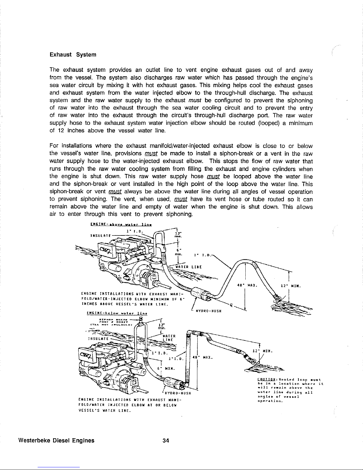
Exhaust System
The
exhaust system provides
an
outlet line to vent engine exhaust
gases
out
of
and
away
from the
vessel.
The
system also discharges
raw
water which
has
passed
through
the
engine's
sea
water circuit
by
mixing
IT
with hot exhaust
gases.
This
mixing helps cool the exhaust
gases
and
exhaust system from the water injected elbow to the through-hull discharge.
The
exhaust
system
and the
raw
water supply to the exhaust must
be
configured to prevent
the
siphoning
of
raw
water into the exhaust through the
sea
water cooling circuit
and
to prevent the entry
of
raw
water into the exhaust through the
circuIT's
through-hull discharge port.
The
raw
water
supply hose to the exhaust system water injection elbow should
be
routed (looped) a minimum
of
12
inches above the
vessel
water line.
For installations where the exhaust manifold/water-injected exhaust elbow
is
close to or below
the vessel's water
line,
provisions
~
be
made to install a siphon-break or a vent
in
the
raw
water supply hose to the water-injected exhaust elbow.
This
stops the flow of
raw
water that
runs
through the
raw
water cooling system from filling the exhaust
and
engine cylinders when
the engine
is
shut down.
This
raw
water supply
hose
~
be
looped above
the
water line
and
the siphon-break or vent installed in the high point of the loop above the water
line.
This
siphon-break or vent
~
always
be
above the water line during
all
angles of
vessel
operation
to prevent siphoning.
The
vent,
when
used,
~
have
ITS
vent
hose
or tube routed so
it
can
remain
above the water line
and
empty of water when the engine
is
shut down.
This
allows
air to enter through this vent to prevent siphoning.
ENGINE-aboy.
wattr
lin«
1"'
I.
D.
INSULATE
ENGINE
INSTALLATIONS
WITH
EXHAUST
~ANI
~OlOJWAT[R-INJ[CTED
ELBOW
~IHIHU~
OF
G-
INCHES
ABOVE
VESSEL'S
WATER
LINE.
EHGI"(-b~low
w~t,r
..
r"HO
......
"'
....
!'flRT " :13327
WATER
LIKE
HYDRO-HUSH
EN61NE INSTALLATIONS
WITH
EXHAUST
MANI-
FOLD/WATER
INJECTED
ELBOW
AT
OR
BELOW
VESSEL'S
WATER
LINE.
Westerbeke Diesel Engines
34
HYDRO-HUSH
I
48-
MAX.
J
~:Vented
loop
.ust
be
in a IDeation
where
it
will
re.~in
above
the
water
lin.
during
~ll
angle.
of
ves.el
operation.
Page 41

The
raw
water supply through-hull
sea
cock fittings must
be
of
the
flush-hull type. High-speed
scoop type of fittings should not
be
used
as
they tend to encourage siphoning when
the
vessel
is
under
sail
or being towed. The exhaust discharge from
the
water lift muffler should
be
routed
well above the water line then downward to the through-hull discharge.
This
routing
will
prevent
raw
water entry if the through-hull discharge fitting becomes submerged
when
the
vessel
heels
or rolls while under
way.
The
exhaust through-hull discharge fitting must not
be
restrictive,
otherwise
IT
will create unwanted back-pressure
in
the
system.
Exhaust Back-Pressure
The
exhaust discharge
hose
must
be
of
adequate
size
and
minimal
run
to prevent excessive
exhaust back-pressure. Exhaust back-pressure should
be
checked before the engine
is
put into
service. Excessive back-pressure will affect the engine's performance.
Measure back-pressure at the exhaust elbow when
the engine
is
running at
3600
rpm.
Back-pressure,
as
measured by a manometer, a pressure gauge,
or water column, should not
be
over the specifications
listed below
To measure for back-pressure, use a mercury
manometer, a pressure gauge, or a water column.
A boatyard or marine mechanic should
have
a
manometer or a pressure gauge.
A water column
can
be
made by taking a clear
plastic tube
and
taping one
end
of
the
tube along
a yardstick
and
fitting the other
end
of
the tube
with a 1/4 inch
NPT
(National Pipe
Tap)
pipe fitting.
"
..
"
"
"
Mercury
Manometer
-Insulation
Exhaust
Elbow
Exhaust
.t:-~.
\
Measure back-pressure at the exhaust elbow when
the engine
is
running at
3600
rpm under
load.
Measuring Back Pressure
Back-pressure,
as
measured by a gauge in-
strument, should not exceed the
following
specifications:
2 inches of mercury
27
inches of water
in
a water column
15.6
ounces
PSI
1.0
PSI
Excessive back-pressure
can
be
caused
by
a
small
diameter exhaust
hose, a small
muffler,
sharp bends
in
the exhaust
hose,
improper
fittings, water pockets,
and
a high volume of
water
in
the exhaust
system
due to the length
of the exhaust discharge
hose.
The
use
of
elbows
and
fittings
in
the exhaust discharge
hose's routing should
be
limited since
these
35
'.
-
Water Column
Westerbeke Diesel Engines
Page 42
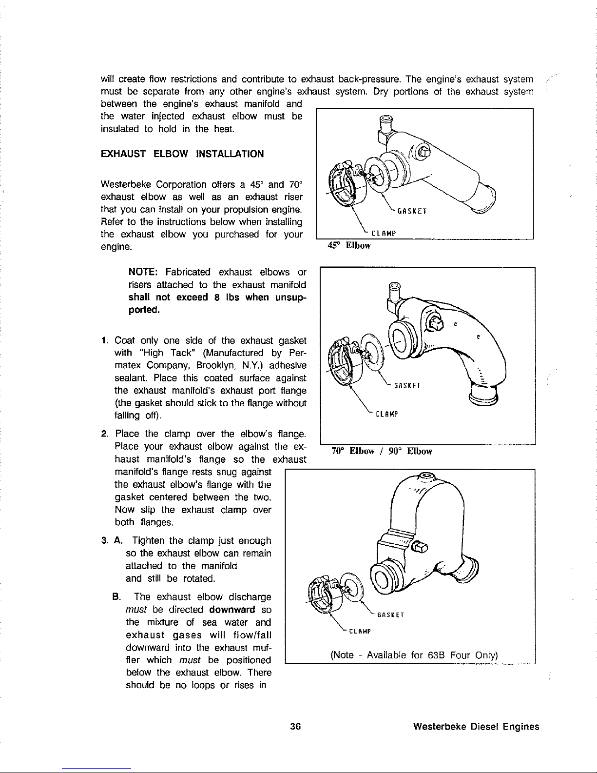
will create flow restrictions
and
contribute to exhaust back-pressure.
The
engine's exhaust
system
must
be
separate from any other engine's exhaust
system.
Dry portions of
the
exhaust
system
between the engine's exhaust manifold
and
the water injected exhaust elbow must
be
insulated to hold
in
the
heat.
EXHAUST ELBOW INSTALLATION
Westerbeke Corporation offers a 45'
and
70'
exhaust
el
bow
as
well
as
an
exhaust riser
that you
can
install
on
your propulsion
engine.
Refer
to
the
instructions below
when
installing
the exhaust elbow you purchased for your
engine.
NOTE:
Fabricated exhaust elbows or
risers attached to the exhaust manifold
shall not exceed 8 Ibs when unsupported.
1.
Coat only
one
side
of the exhaust gasket
with
"High Tack" (Manufactured
by
Per-
matex Company, Brooklyn,
N.Y.)
adhesive
sealant.
Place
this coated surface against
the exhaust manifold's exhaust port flange
(the gasket should stick to the flange without
falling
off).
2.
Place
the
clamp over the elbow's
flange.
Place your exhaust elbow against the
ex-
haust manifold's flange so the exhaust
GASKET
CLAMP
45'
Elbow
CLAMP
70' Elbow I
90'
Elbow
manifold's flange
rests
snug against
r------------=~=------------,
the exhaust elbow's flange with the
gasket centered between the two.
Now
slip the exhaust clamp over
both flanges.
3.
A.
Tighten the clamp just enough
so
the
exhaust elbow
can
remain
attached to the manifold
and
still
be
rotated.
B.
The
exhaust elbow discharge
must
be
directed downward
so
the mixture of
sea
water
and
exhaust
gases
will
flow/fall
downward into the exhaust muffler which
must
be
positioned
below the exhaust elbow.
There
should
be
no loops or
rises
in
(Note - Available for
63B
Four Only)
36 Westerbeke Diesel Engines
Page 43

the
exhaust
hose
connected between the exhaust elbow
and
the muffler,
as
these would
trap water
and
possibly allow water to flow back into the engine during starting or at shut
down.
4.
Adjust the elbow
by
rotating ~ until the desired alignment with the exhaust piping
is
acquired.
5.
Carefully tighten
the
clamp between 8 to
10
Ib-ft, or
24
to
35
Ib-in, or
0.27
to
0.41
kg-m.
ICAUTIONI
10
Lb-ft Torque Limit
Approach the
10
Ib-ft torque limit with caution.
The
clamp's threads will break
if
more
than
10
Ib-ft
is
applied to the clamp.
6.
When
the engine
is
started for the first time with the
new
elbow, check this
exhaust
manifold/elbow connection for
leaks.
If a leak
eXists,
correct it immediately.
Exhaust
System Failures
When
the engine's
raw
water
is
fed
into
an
exhaust system
so
that the full stream
of
this water
strikes a surface, erosion takes
place.
This
erosion may
cause
premature failures.
The
proper
design
of
either a water jacketed or water injected "wet" exhaust system to prevent this problem
requires that the
raw
water inlet
be
positioned
so
that the entering stream
of
raw
water does
not directly strike a
surface.
In
addttion, the velocity of the entering
raw
water stream should
be
as
low
as
possible, which
can
be
achieved
by
having inlet fittings
as
big
in
diameter
as
possible.
I
WARNiNG
I
Carbon Monoxide Gas Is Deadly!
Carbon monoxide
is
a dangerous
gas
that
can
cause unconsciousness
and
is
potentially
lethal.
Some
of
the symptoms or signs of carbon
monoxide inhalation or poisoning
are:.
o Dizziness
o Vomiting
o Intense Headache
o Muscular Twitching
o Weakness and Sleepiness
o Throbbing in Temples
If
you
experience
any
of
the
above symptoms, get out into
fresh
air immediately.
The
best
protection against carbon monoxide poisoning
is
a daily inspection
of
the complete
exhaust
system.
Check
for
leaks
around manifolds, gaskets,
and
welds.
Make
sure
exhaust
lines
are
not heating surrounding
areas
excessively.
If
excessive heat
is
present, correct
the
situation immediately.
If
you
notice a change
in
the sound or appearance of the exhaust
system,
shut down the unit immediately
and
have
the
system
inspected
and
repaired at once by a
qualified mechanic.
37
Westerbeke Diesel Engines
Page 44

Make
sure there
are
no unnecessary objects suspended from any portion of the exhaust
lines.
Exhaust risers installed off the exhaust manifold should not exceed 8 Ibs
in
total weight
when
rigidly constructed. Excessive weight could
cause
deflection or distortion of the manifold resulting
in
damage and/or internal leaks. Inspect insulated portions
of
the exhaust system to ensure
there
is
no deterioration of the insulation.
I
CAUTION
I
Do
Not Overcrank!
Prolonged cranking intervals without the engine starting
can
result
in
filling the engine-
mounted exhaust system with
raw
water coolant. This may happen because the
raw
water
pump
is
pumping
raw
water through the
raw
water cooling system during cranking.
This
raw
water
can
enter the engine's cylinders by way of the exhaust manifold once the ex-
haust
system fills. Prevent this from happening by closing the
raw
water supply through-hull
shut-off, drain the exhaust muffler,
and
correct the
cause
for the excessive engine cranking
needed
to obtain a start. Engine damage resulting from this type
of
raw
water entry
is
not
a warrantable
issue;
the owner/operator should keep this
in
mind.
Raw Water Intake System
Make
sure
the intake system (raw water cooling system)
is
in
proper order. Check that the
hull inlet,
sea
cock
and
strainer
are
unobstructed.
Sea
cocks
and
strainers should
be
at
least
one
size greater than the inlet thread
of
the
sea
water pump.
The
strainer should
be
of
the
type that may
be
withdrawn for cleaning while the
vessel
is
at
sea
and
should
be
mounted
below the water line to ensure self-priming.
Inspect the
raw
water lines to
make
sure
there
are
no collapsed sections, which would restrict water
flow.
Make
sure there
are
no air
leaks
at any
of
the
connections
use
double clamps
on
hose
connections below water
line.
Cooling System
The
engine
is
fresh water-cooled
by
an
engine-mounted heat exchanger.
Raw
water
is
used
as
the
heat exchanger's cooling medium.
Raw
water
is
pumped into the exchanger
by a raw
water pump
and
is
then injected into the exhaust discharge, carrying with
it
the
heat
removed
from the engine's fresh water cooling
system.
Raw
water should
be
supplied to the
raw
water pump through a flush-type through-hull fitting
using a wire-reinforced
hose
between
the
through-hull fitting
and
the
raw
water pump.
This
raw
water should
be
directed through a visual-type
raw
water strainer
and
then delivered to the
pump. Hoses routed from the through-hull fitting to the strainer and to the
raw
water pump
should
be
wire-reinforced to prevent the
hose
from collapsing during the generator's operation
(suction from the pump
may
collapse a non-reinforced
hose).
Raw
water strainers should be
mounted at or below the water line to
make
sure
the
raw
water line remains primed after
shutdown.
Westerbeke Diesel Engines
38
Page 45
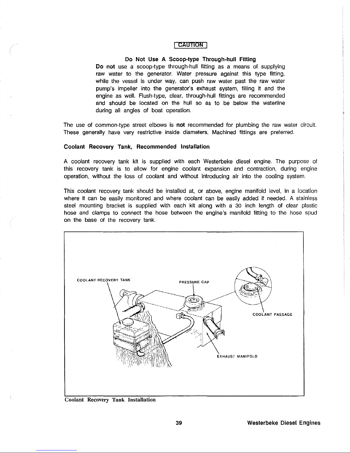
I
CAUTION
I
Do Not Use A Scoop-type Through-hull Fitting
Do not
use
a scoop-type through-hull fitting
as a means
of supplying
raw water to the generator. Water pressure against this type fitting,
while the
vessel
is
under
way,
can push
raw
water past the
raw
water
pump's
impeller into the generator's exhaust
system,
filling it
and
the
engine
as
well.
Flush-type, clear, through-hull fittings are recommended
and
should
be
located on the
hull
so
as
to
be
below the waterline
during
all
angles of boat operation.
The
use
of common-type street elbows
is
not recommended for plumbing the
raw
water circuit.
These
generally
have
very restrictive inside diameters. Machined fittings are preferred.
Coolant Recovery Tank, Recommended
Installation
A coolant recovery tank
kit
is
supplied with
each
Westerbeke diesel engine.
The
purpose of
this recovery tank
is
to allow for engine coolant expansion
and
contraction, during engine
operation, without the
loss of coolant
and
without introducing air into the cooling
system.
This coolant recovery tank should
be
installed
at,
or above, engine manifold
level,
in
a location
where it can
be
easily monitored
and
where coolant
can
be
easily added if needed. A stainless
steel
mounting bracket
is
supplied with
each
kit along with a
30
inch length of clear plastic
hose
and
clamps to connect the hose between the engine's manifold fitting to the hose
spud
on the base of the recovery tank.
COOLANT
RECOVERY TANK
PRESSURE CAP
COOLANT
PASSAGE
EXHAUST
MANIFOlD
Coolant Recovery
Tank
Installation
39
Westerbeke Diesel Engines
Page 46
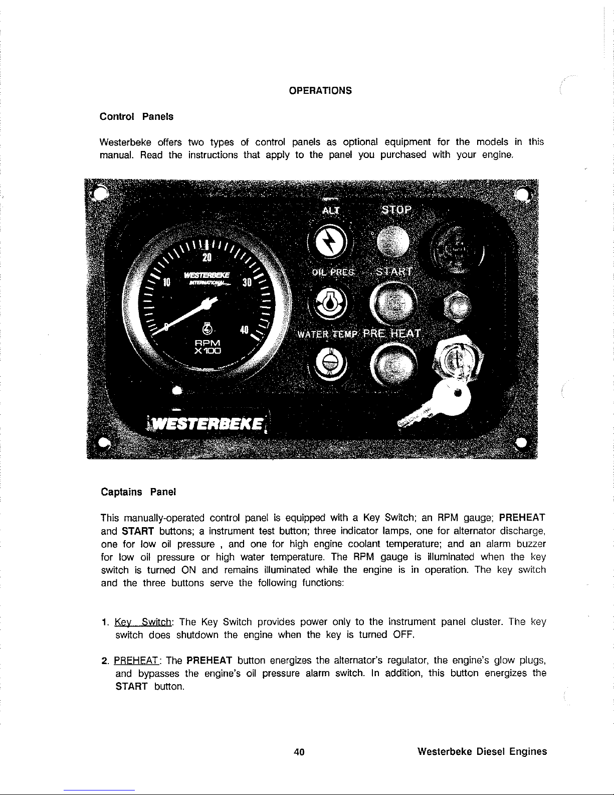
OPERATIONS
Control Panels
Westerbeke offers two types
of
control
panels
as
optional equipment for the models
in
this
manual.
Read
the instructions that apply to
the
panel
you purchased with your engine.
Captains Panel
This manually-operated control
panel
is
equipped with a
Key
Switch;
an
RPM
gauge;
PREHEAT
and
START
buttons; a instrument test button; three indicator lamps, one for alternator discharge,
one for low
oil
pressure ,
and
one for high
engine
coolant temperature;
and
an
alarm buzzer
for low oil pressure or high water temperature.
The
RPM
gauge
is
illuminated when the
key
switch
is
turned
ON
and
remains
illuminated while
the
engine
is
in
operation.
The
key
switch
and
the three buttons
serve
the
following functions:
1.
Key
Switch: The
Key
Switch provides power only to the instrument panel cluster. The key
switch does shutdown the engine
when
the
key
is
turned
OFF.
2.
PREHEAT:
The
PREHEAT
button energizes
the
alternator's regulator, the engine's glow plugs,
and
bypasses the engine's
oil
pressure
alarm
switch. I n addition, this button energizes the
START
button.
40
Westerbeke Diesel Engines
Page 47
3.
START:
The
START button, when pressed, energizes the starter's solenoid which cranks
the
engine.
This
button will not operate electrically unless
the
PREHEAT button
is
pressed
and
held
at the
same
time.
4.
Test
Button:
The
Test Button, located above the key switch, tests the alternator,
the
oil
pressure, and the water temperature control circuits.
When
this button
is
pressed, the
alternator, the oil pressure,
and
the water temperature indicator lights illuminate
in
addition
to sounding the
alarm
buzzer.
5.
Alarm:
The
alarm
is
located above the test button
and
will sound if
the
engine's
oil
pressure
falls below
15
psi.
In
this
event,
the
alarm
will
emit a pulsating
signal.
The
alarm will also
sound if the water temperature
in
the
fresh
water cooling circuit
rises
to
205'
F.
In
this
event,
the alarm will emit continuous
signal.
NOTE:
The
alarm will sound
when
the
Key
Switch
is
turned
ON.
This
sounding
is
normal for the engines covered
in
this
manual.
Once the
engine starts, and the engine's oil pressure reaches
15
psi,
the alarm
will
silence.
Westerbeke
Diesel Engines
41
Page 48

Admirals Panel
This manually-operated control
panel
is
equipped with a key switch and
an
RPM
gauge with
an
ELAPSED TIME meter which
measures
the engine's running time
in
HOURS
and
in
1/10
hours. The panel also includes a water temperature gauge which indicates water temperature
in
degrees Fahrenheit
(WATER'
F),
an
oil
pressure gauge which measures the engine's
oil
pressure
in
pounds per square inch (OIL
PSI),
and a DC
control circuit voltage gauge which
measures the system's voltage
(VOLTS).
All
gauges
are
illuminated when the
key
switch
is
turned
ON
and
remain
illuminated while the engine
is
in
operation. The panel also contains
two rubber-booted push buttons,
one
for PREHEAT
and
one for START.
1.
Key Switch:
The
Key
Switch provides power only to the instrument cluster.
The
key
switch
does shutdown the engine
when
the
key
is
turned
OFF.
2.
PREHEAT:
The
PREHEAT button energizes the alternator's exciter, the engine's glow plugs,
and
bypasses the engine's protective
oil
pressure alarm switch.
In
addition, this button
energizes the
START button.
3.
START:
The
START button,
when
pressed, energizes the starter's solenoid which cranks the
engine. This button
will not operate electrically unless the PREHEAT button
is
pressed
and
held at the
same
time.
4.
Alarm:
The alarm
is
located above the test button
and
will sound if the engine's oil pressure
falls
below
15
psi.
In
this
event,
the alarm will emit a pulsating signal.
The
alarm will also
sound if the water temperature
in
the fresh water cooling circuit rises to 205'
F.
In
this
event,
the alarm will emit continuous signal.
42 Westerbeke Diesel Engines
Page 49

NOTE:
The
alarm
will sound when
the
Key
SWitch
is
turned
ON.
This
sounding
is
normal
for
the
engines covered
in
this
manual.
Once the
engine starts,
and
the engine's
oil
pressure reaches 15
psi,
the alarm
will
silence.
*5. Water Temperature
Gauge:
This
gauge
is
graduated
in
degrees Fahrenheit and
is
illuminated
while the
Key
Switch
is
turned
ON.
The
engine's normal operating temperature
is
170 - 190°
F (77 - 88°C).
*6.
Oil
Pressure
Gauge:
This
gauge
is
graduated
in
pounds per square inch
(PSI)
and
is
illuminated while the
Key
Switch
is
turned
ON.
The
engine's normal operating
oil
pressure
ranges
between
30
- 60
PSI.
'NOTE:
When
the engine
is
shut down, with the
Key
Switch turned
OFF,
the water temperature gauge
will
continue to register the last
temperature
reading
indicated by the gauge before electrical power
was
turned
OFF
The
oil pressure gauge will
fall
to zero when the
Key
Switch
is
turned
OFF.
The
temperature gauge will once again register the
engine's true temperature once
electrical power
is
restored to the gauge.
NOTE:
A separate alarm buzzer with
harness
is
supplied with every
Admiral
Panel.
The
installer
is
responsible for electrically connecting the
buzzer to the four-pin connection on the engine's
electrical
harness.
The
installer
is
also responsible for installing the buzzer
in
a location
will
be
dry
and
where
it
will
be
audible to the operator should
it
sound
while the engine
is
running.
The
buzzer
will
sound
when
the ignition
key
is
turned
ON
and
should silence
when
the engine
has
started
and
when the engine's
oil
pressure
rises
above 15
psi.
Automatic Alarm System
High
Water
Temperature Alarm
An
alarm buzzer
has
been
supplied with the instrument
panel.
If
the engine's fresh water
coolant reaches 205° F
(96°
C), this switch
will
close sounding the alarm which will emit
a
continuous
signal.
Low Oil Pressure Alarm
A low oil pressure
alarm
switch
is
located off the engine's oil gallery.
This
switch monitors
the
engine's oil
pressure.
Should
the engine's
oil
pressure
fall
to 10 - 15
psi,
the switch
will
close sounding the
alarm.
In
this
event,
the alarm will emit a pulsating signal.
Westerbeke Diesel Engines
43
Page 50

Description of the Starting System
Westerbeke diesel engines
use
electric starters assisted
by
glow plugs for both normal
and
cold weather starting.
The
figure below shows a cross-sectional
view
of
one
cylinder.
The
glow
plug
is
located
in
the combustion chamber
so
that
its
tip
is
in
the injector nozzle's spray
path.
When
the glow plug
is
energized by the PREHEAT button, the plug glows
red
at the tip
and
assists
in
igniting the
fuel.
The
result
is
a rapid start with less
wear
on
the
starter.
This
system
is
common to Westerbeke
Diesels.
The
start circuitry
is
designed
so
that the
PREHEAT button
ll:UW.
be
depressed for the time specified
in
the
Preheat
Table
(page
46).
Then,
while keeping the PREHEAT button engaged, the START button
is
depressed to crank
the engine.
GLOW
PLUG
NOTE:
The
START switch will not energize unless the PREHEAT button
is
depressed.
When
depressing the preheat switch,
The
glow plugs
in
the cylinder
head
are
activated.
Use
the preheat intermittently to avoid
overheating the glow plugs.
44
Westerbeke Diesel Engines
Page 51

Preparation For Starting
Take
the steps described below
in
starting your
engine
for the first time or after a prolonged
shutdown or layup.
Fill
your engine with
oil
up to or near the upper limit
on
the dipstick (the installation angle
may
have
an
affect
on
the dipstick
reading). Select readily available lubricating
oil with
an
API
specHication of
CC
or
CD
and
an
SAE
number suitable for the
temperature
in
your operating
area.
Fill
the transmission to the FULL mark
on
the dipstick with the correct lubricant.
For the quantities of oil and transmission
fluid needed
in
your engine, refer to the
"System Specification" section
of
this
manual.
Fill
the
fuel
tank with a good grade of
No.
2 diesel fuel
and
prime the
fuel
system up to the
engine.
When
returning
and the engine
is
ready to start.
Upper Limit
(Normal
Limit
fuel
is
free
of
air,
the engine's
fuel
system
is
bled
Each
unit
is
supplied with a coolant recovery kit (#24977)
as
standard equipment which
!111.l&.
be
installed
and
the following applies:
A.
Remove
the pressure cap from
the
engine's exhaust
manHold,
open the air
bleed
petcock
on
the heat exchanger
and
slowly fill the engine's cooling
system
with a mixture of water
and
antHreeze
suitable for your temperature
zone.
Close the petcock on
the
exchanger
once coolant flows from it.
Operate the engine
and
observe the coolant
level
in
the manifold.
Maintain this
level
to the base
of
the filler
neck.
Once
the
engine
reaches
its
operating
temperature
(170 - 190'
F),
make
sure there
is
no
problem with coolant flow through the
manHold.
Top off the cooling
system
and
install
the pressure
cap.
B.
Make
sure the plastic recovery tank
is
properly mounted
near
the
unit
in
a location where
it
can
be
monitored
and
filled easily.
The
recovery tank should be mounted at manifold
level
or above. For installations that require
it,
the
plastic recovery tank
can
be
mounted
below the exhaust manifold's
level.
C.
Add
coolant to the plastic coolant recovery tank once
you
have
topped off the exhaust
manHold
full right to the filler neck top.
NOTE:
This
is
a closed type cooling
system
and
little or no coolant
should
be
lost from the system. If excessive coolant
is
lost, artifically
pressurize the system
and
inspect for
the
cause.
With
the
manifold filled
and
air expelled, fill the coolant recovery tank
half
full.
Monitor this
recovery tank daily
and
add coolant
as
needed.
Periodically check that
the
manHold
is
full when cold.
Westerbeke Diesel Engines
45
Page 52
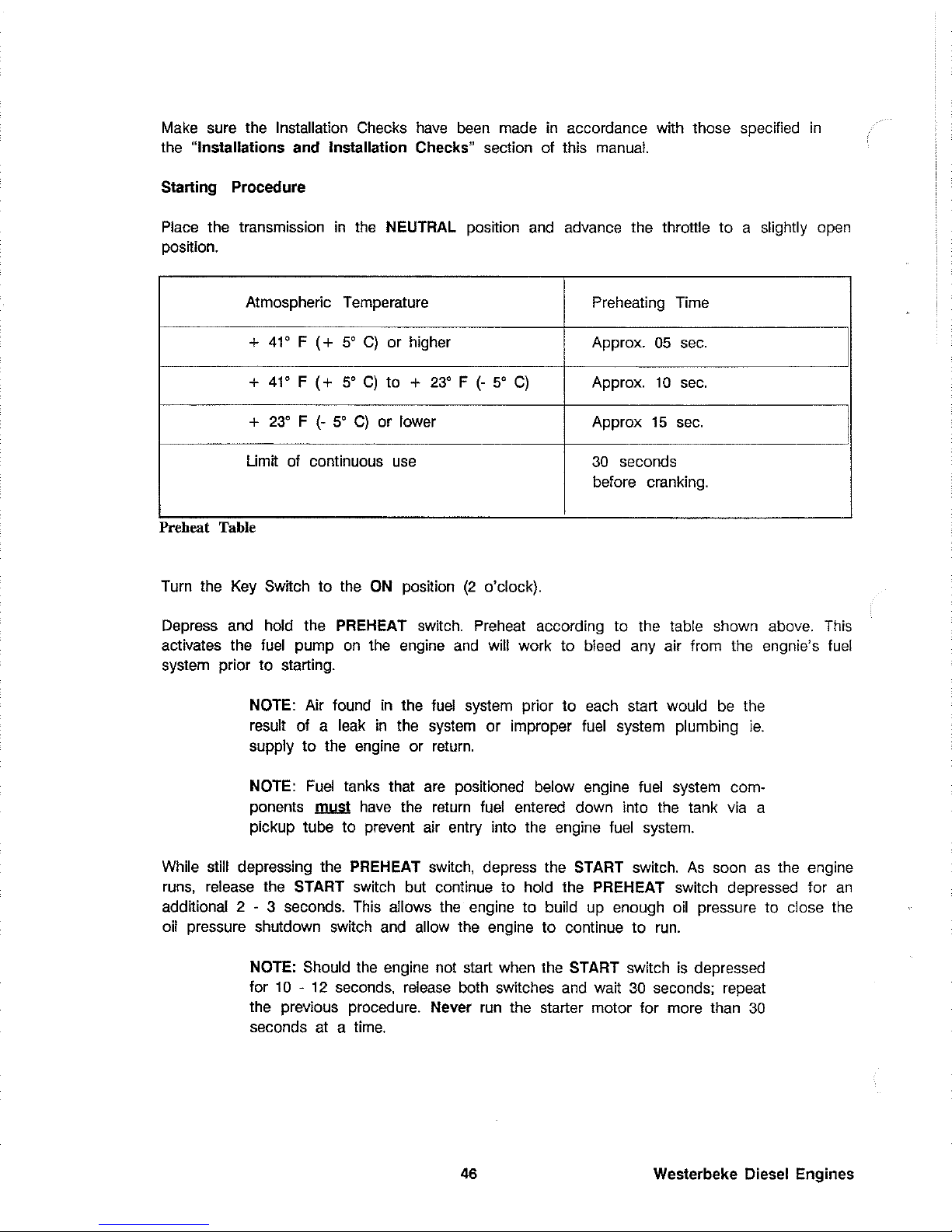
Make
sure the Installation Checks
have
been
made
in
accordance with those specified
in
the "Installations and Installation Checks" section of this
manual.
Starting Procedure
Place
the transmission
in
the
NEUTRAL position
and
advance the throttle to a slightly
open
posITion.
Atmospheric Temperature
Preheating Time
+
41'
F
(+
5'
C)
or higher
Approx.
05
sec.
+
41'
F
(+
5'
C)
to +
23' F (-
5'
C)
Approx. 10
sec.
+
23' F (-
5'
C)
or lower
Approx 15
sec.
limIT
of
continuous
use
30 seconds
before cranking.
Preheat Table
Turn the
Key
SWITch
to the
ON
posITion
(2
o'clock).
Depress
and
hold the PREHEAT switch.
Preheat
according to the table shown above.
This
activates the
fuel
pump
on
the engine
and
will work to
bleed
any air from the engnie's
fuel
system prior to starting.
NOTE:
Air found
in
the
fuel
system prior
to
each
start would
be
the
result of a
leak
in
the
system
or improper
fuel
system plumbing
ie.
supply
to
the engine or
return.
NOTE:
Fuel
tanks that
are
positioned below engine
fuel
system com-
ponents
~
have
the
return
fuel
entered down into
the
tank
via
a
pickup tube to prevent air entry into
the
engine
fuel
system.
While
still depressing the PREHEAT switch, depress the START switch.
As
soon
as
the engine
runs,
release the START
SWITch
but continue to hold the PREHEAT switch depressed for
an
additional 2 - 3 seconds.
This
allows
the
engine to build
up
enough
oil
pressure to close
the
oil pressure shutdown switch
and
allow the engine to continue to
run.
NOTE: Should
the
engine not start when the START switch
is
depressed
for
10 - 12 seconds,
release
both switches
and
wait 30 seconds; repeat
the previous procedure. Never
run
the starter motor for more than 30
seconds at a
time.
46
Westerbeke Diesel Engines
Page 53

Check
all
the instruments on the
panel
for proper operation
and
make
sure
raw
water discharges with the exhaust discharge once the engine starts.
Once the engine
starts,
allow it to
run
for a few minutes to
warm
up
and
stabilize while the engine's instruments
are checked for proper oil pressure
and
battery charging voltage. Never attempt
to engage the starter while the
engine
is
running.
Voltage
Drop
From
Glow
Plug
NOTE:
Some
unstable running
may
occur
in
a cold engine, but this
condition
should smooth out
as
the operating temperature moves into
the
170 -1900 F
(77 -880 C)
range.
Proper glow plug function
is
indicated
by
a voltmeter drop when the PREHEAT switch
is
depressed.
This
drop will
be
slight but discernible. If no voltage drop
is
noted,
it
may indicate
defective
glow plugs or a faulty
preheat
circuit (check for loose connections or faulty preheat
solenoid).
I
CAUTION
I
Prolonged cranking can damage the engine!
Prolonged cranking intervals without the engine starting
can
result
in
filling
the
engine mounted exhaust system with
raw
water coolant. This
may happen because
the
raw
water pump
is
pumping
raw
water through
the
raw
water cooling
system
during cranking.
This
raw
water
can
enter
the engine's
cylinders
by
way
of
the exhaust manifold once the exhaust
system
fills. Prevent this from happening by closing the
raw
water supply
through-hull
shut-off, drain
the
exhaust muffler,
and
correct the cause
for
the
excessive
engine
cranking needed to obtain a start. Engine
damage
resulting from this type
of
raw
water entry
is
not a warrantable
issue;
the owner/operator should keep this
in
mind.
Westerbeke Diesel Engines 47
Page 54

Starting Under Normal Conditions
Follow the procedure
below for normal starting of the engine:
1.
Check the engine
and
transmission lubricant levels
and
fill,
if
necessary.
2.
Make
sure there
is
sufiicient
fuel
on
board.
Keep
fuel tank(s)
as
full
as
possible. Check
the
fuel
filters
and
water separators for the presence of contaminants and/or
water.
Drain
and clean them
as
needed.
3.
Check the coolant
level
in the plastic recovery
tank.
Add
coolant solution
as
needed.
NOTE: Excessive loss
of
coolant from the plastic recovery tank indicates
a
cooling
system
leak.
Check the entire cooling system
and
pressurize
the system to
locate the
leak.
In
cases
of
excessive coolant
loss,
the
system must
be
refilled
as
outlined under the "Preparation For Starting"
section
of
this
manual.
4.
Check for oil
and
fuel
leaks,
particularly if signs of such leaks
are
found
on
the bottom
of the engine or
below the
engine.
Start the engine
in
accordance with the "Starting Procedure" instructions found
on
page
46,
and
allow the engine's operating temperature to reach 140 -
150'
F before operating the engine
underway.
Starting Under
Cold Conditions
Under
extremely cold temperatures, the following conditions
can
occur. Follow the instructions
listed below when operating your engine
in
cold weather.
Lubricating Oil
Turns
Viscous -
Make
certain that the lubricating oil
used
conforms with
the
ratings for the prevailing atmospheric temperature.
Voltage
Across
The
Battery
Terminals
Drops - Make certain that the battery
is
fully charged to
minimize
voltage drop across the battery terminals.
The
Temperature Of
The
Intake Air Is Low And
The
Compression Temperature Does Not
Rise
Enough - Allow the glow plugs to operate sufficiently to
aid
in
starting during the preheat period
whenever the temperature
of
the intake air
is
low and when the compression temperature does
not
rise
enough.
Refer
to the preheat chart found
in
the "Starting Procedure" section,
page
46.
48 Westerbeke Diesel Engines
Page 55

Stopping Procedure
To
stop the engine bring the throttle to a idle position, place the transmission
in
neutral.
Scan
instrument
panel
gauges. Allow the engine to idle for a few moments to stablize temperatures.
Turn the key to the off position. This opens the
DC
circuit to the instrument
panel
and
engine
de-energizing the fuel solenoid
on
the injection pump stopping
fuel
flow from it
and
stopping
the engine.
Fuel Injection Pump
NOTE: Only the 636 Four model
has
a mechanical shut-off
arrn
on
the
outboard side of the injection purnp that can
be
used
to stop the
engine by mechanical
means.
When
this rnode
is
used
the
fuel
solenoid
on
the injection pump
is
disabled
by
removing
the
internal plunger
and
spring frorn the solenoid.
With the engine stopped, turn the
key
switch turned to the
OFF
position
(12
o'clock).
If
the
Key
Switch
is
left
ON,
the battery will discharge.
An
engine alarm buzzer
is
provided to warn
the operator of this condition
(Key
Switch ON).
The
best method of preventing the battery from
discharge
is
to remove the
key
from the
Key
Switch after stopping the
engine.
Westerbeke Diesel Engines
49
Page 56

Engine Break-In Procedures
Although your engine
has
experienced a minimum of
one
hour of test operations to
ensure
accurate assembly
and
proper operation
of
all
systems,
break-in time
is
required.
The
service
life of your engine
is
dependent upon how
the
engine
is
operated and serviced during
its
initial
50
hours of
use.
Your
new
engine requires approximately
50
hours
of
initial conditioning operation to break
in
each moving part
in
order to maximize
the
performance
and
service life of the
engine.
Perform
this conditioning carefully, keeping
in
mind
the following:
1.
Start the engine according to the "Starting Procedure" section found on page
46;
run
the
engine at fast idle while checking that
all
systems
(sea
water pump,
oil
pressure, battery
charging) are functioning.
2.
Allow the engine to
warm
up
(preferably by running at fast
idle)
until the water temperature
gauge moves into the 130-140'
F
range.
3. While using the vessel,
run
the
engine
at varying engine speeds for the first
25
hours.
4. Avoid rapid acceleration, especially
with
a cold
engine.
5.
Use
caution not to overload the
engine.
The
presence
of
a gray
or
black
exhaust,
and
the inability of the engine to
reach
its
full
rated
speed,
are
signs
of
an
overload.
6.
During the next
25
hours,
the
engine
may
be
operated at varying engine
speeds,
with
short runs at
full rated
rpm.
Avoid prolonged idling during this break-in period.
Breaking-in a new engine basically involves seating
the
piston rings to the cylinder walls.
This
cannot
be
accomplished by long periods
of
running at
Idle,
nor by early running
at
full
rpm.
Idle running may glaze the cylinder
walls,
resulting
in
excessive oil consumption
and
smoky
operation. Excessive speed or
heavy
overloading, especially with a cold
engine,
may
cause
scoring
of
the cylinder
walls,
producing similar
results.
As
indicated above, operate
the
engine
in
moderation during the 50-hour break-in period. (Don't
baby the engine, but do not abuse
it.)
50 Westerbeke Diesel Engines
Page 57
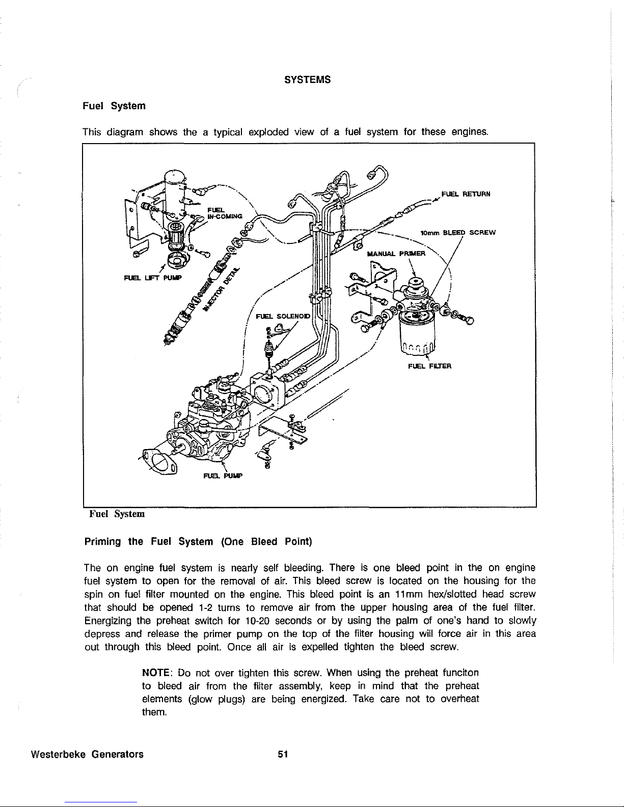
SYSTEMS
Fuel System
This diagram shows the a typical exploded view of a
fuel
system
for these engines.
REllJRN
10mm BLEED
SCREW
FLEL
FIIJ"ER
Fuel System
Priming the Fuel System (One Bleed Point)
The
on
engine
fuel
system
is
nearly
self
bleeding.
There
is
one
bleed
point
in
the
on
engine
fuel
system
to open for the
removal
of
air.
This
bleed
screw
is
located on the housing for the
spin
on
fuel
filter mounted
on
the
engine.
This
bleed
point
is
an
11
mm
hex/slotted
head
screw
that should be opened
1-2
turns to
remove
air from the upper housing
area
of the
fuel
filter.
Energizing the preheat switch for
10-20
seconds or
by
using the palm of one's hand to slowly
depress
and
release
the primer pump
on
the
top
of
the filter housing will force air
in
this
area
out through this
bleed
point. Once
all
air
is
expelled tighten
the
bleed
screw.
NOTE:
Do
not over tighten this
screw.
When
using the preheat funciton
to
bleed
air from the filter
assembly,
keep
in
mind that the preheat
elements (glow plugs)
are
being
energized.
Take
care not to overheat
them.
Westerbeke Generators
51
Page 58

Once
the
fuel filter assembly
is
bled
of air
and
the bleed screw tightened
again,
depress the
preheat switch
10-20
seconds or slowly pump the primer on the
fuel
filter housing to force
any
air
in
the
system between the filter housing and the injection pump out of the
system
and
back to the fuel tank through
the
return.
Diesel Fuel
USE # 2 DIESEL FUEL WITH A CETANE RATING OF 45 OR BETTER. NEVER USE KEROSENE
OR
HEAVY OIL.
In
cold weather particularty, water vapor
is
produced by condensation when air
is
present in the
fuel
tank.
Keep
the
fuel
tank(s)
full
and completely free of dirt
and
water.
Fuel Filter/Water Separators
A primary
fuel
filter of the water separating type
l11Lill.
be
installed between the
fuel
tank
and
the
engine.
To remove water
and
other contaminants from the
fuel
before they
can
be
carried
to
the
fuel
system
on
the
engine.
Most installers included with the generator installation package a type of filter/water separator
for they
are
aware of the problems contaminants
in
the fuel
can
cause
-all
of which
are
not
warrantable through Westerbeke.
A typical
fuel filter/water separator
is
illustrated
in
this diagram.
This
is
the
Raycor Model
500MA.
Keep
in
mind
that
if
a water separator type filter
is
not installed between the
fuel
supply
tank
and
engine-mounted
fuel
system,
any
water
in
the
fuel
will affect the
fuel
pump, engine
fttler,
and
injection
equipment. The owner/operator is
responsible for making certina
the
fuel
reaching the engine's injection equipment
is
free
of impurities. This process
is
accomplished by installing
and
main-
taining a proper filtration/separation
system.
In
addition, any gasoline in
the
fuel
system
will
damage the engine's
fuel
injection pump assembly
and
injectors
as
gasoline does not
have
the
same
lubricating qualities
as
diesel
fuel.
52
IN
Fuel Filter/Water Separator
Westerbeke Generators
Page 59

If
a filter/water separator
is
not installed between
the
fuel
tank
and
the engine-mounted
fuel
system,
water
in
the
fuel
system
will inhibit proper starts and particles will
pass
on
to the lift
pump's filter, eventually clogging
it
and
pass
on into
the
engine's injection equipment.
Notes on Fuel
System
t?VAANiNGij
Shut off the
fuel
service valve at the engine when servicing the fuel
system.
Take
care
in
catching any
fuel
that
may
spill from within the pump when the
base
is
removed.
DO
NOT
allow any smoking, open
flames,
or other sources
of
fire near the
fuel
system
when
servic-
ing. Ensure proper ventilation exists when servicing the fuel system.
On
the previous page
is
a typical exploded view
of a fuel
system for these generator
engines,
which illustrates the self-bleeding
and
priming system
used
by Westerbeke.
The Westerbeke self-bleeding fuel system
is
automatic
in
operation. While the likelihood of
having to service the
system
at
sea
is
slim,
the possibility does
exist.
Therefore,
we
recommend
that
fuel
system banjo
washers,
injector
seat
washers,
a lift pump filter
and
gasket,
and
a fuel
filter
and
gasket
be
carried on board at
all
times. Purchase
needed
spares from your local
Westerbeke Dealer or Distributor. For example, hardware kit
#32050 will supply miscellaneous
fuel
system sealing washers for the 636 Four engine.
Refer
to the last
page
in
your models
parts list for the kit part number for your specific model.
If
a leak should develop at a banjo washer that cannot be corrected by a simple tightening
of the fitting, replace the
sealing
washers.
The
engine
can
be
started by taking the steps described in the
"STARTING
PROCEDURE"
section
of
this manual.
In
cases
where excessive amounts of air exist
in
the
fuel
system,
bleed
the high pressure injector lines. Loosen all these lines at the injectors and crank the engine
with the starter
until
fuel
spurts from between the nut and the
line.
Then
tighten the
nuts.
Westerbeke Generators
53
Page 60
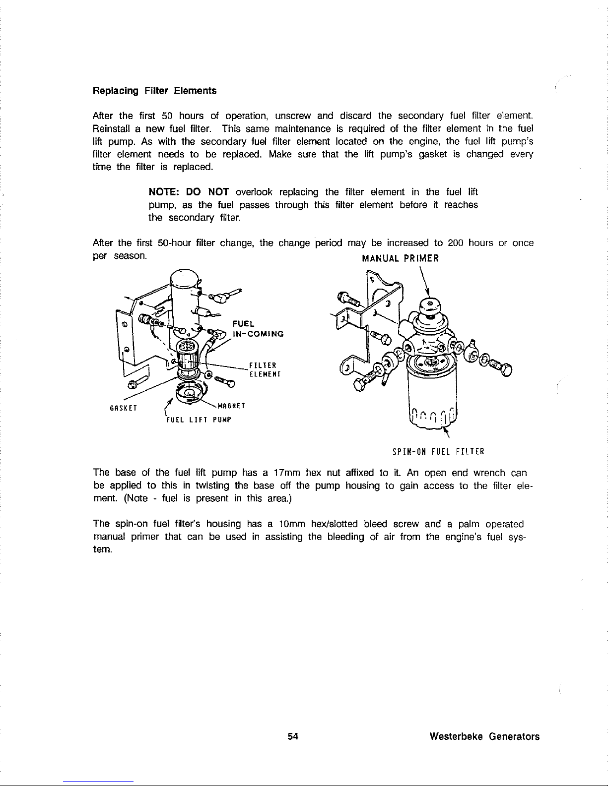
Replacing Filter Elements
After the first
50
hours
of
operation, unscrew
and
discard
the
secondary
fuel
filter
element.
Reinstall a new fuel filter. This same maintenance
is
required of the filter element
in
the fuel
lift
pump.
As
with the secondary fuel filter
element
located on the engine, the
fuel
lift pump's
filter
element needs to
be
replaced.
Make
sure
that the lift pump's gasket
is
changed every
time the filter
is
replaced.
NOTE:
DO
NOT overlook replacing the filter element
in
the
fuel
lift
pump,
as
the fuel
passes
through this filter element before it reaches
the secondary filter.
After the first
50-hour filter
change,
the change period
may
be
increased to
200
hours or once
per season.
MANUAL
PRIMER
TER
GASKET
HET
LIFT
PUMP
SPIN-ON
FUEL
FILTER
The
base of the
fuel
lift pump
has a 17mm
hex
nut affixed to
it.
An
open
end
wrench
can
be
applied
to
this
in
twisting
the
base
off the pump housing to gain access to the filter
ele-
ment.
(Note - fuel
is
present
in
this
area.)
The
spin-on fuel filter's housing
has a 10mm
hex/slotted
bleed
screw
and a palm
operated
manual primer that
can
be
used
in
assisting the bleeding of air from the engine's
fuel
sys-
tem.
54
Westerbeke Generators
Page 61

Fuel Injection Pump
The
fuel
injection pump
is
one
of
the most important components of the diesel engine
and
thus it calls for the utmost care
in
handling. Futhermore, the fuel injection pump
has
been
thoroughly shop adjusted
and
should never
be
readjusted carelessly.
Such
adjustment, whenever necessary, should be performed at
an
authorized service station
as
a precision pump tester
and
skills
are
required to obtain long
and
satisfactory service from
engine's your injection pump:
A.
Allways
use
#2
diesel
fuel
which
is
free
from impurities.
B.
Clean
and
renew
the
fuel filters
on
a regularty scheduled
basis.
CoNSTRUCTION
OF
"VE"
STYLE
INJECTION
PUMP
Overflow
valve
Tension lever
Regulating
valve
Fuel-cut magnet
Plunger
Westerbeke Generators
55
Page 62

Captains Panel
DC
Control Circuit Wiring Diagram #36467
page 1
of
2
R
NG
0 GR M
_W_'_'_
'A
A
~
"10
~e;o
~.
WATER
....
"'TEA
GLO\oIPLU(';$
TEMP
TEMP
".3.'.Mo
~,
SE"DEP.
SWtTCH
O(P["D'~G
o~
,-~
I()<'TU)"'''L
!
"U"S£R
Of
«~
1JIT~
'liST.
i<
C'L'NO(~S)
''''''lEU
CII'ICUIT
Ii'
SREAK!R
~
f[j
#,~
L 1.
BluE
.'
"'"
P~EHEU
ri-TI\
SOLENOID
,
r-
fi4l
"4LT
e..u(
"'1""0
/
(~
0"
- _
PRESSURE
~
~ ~ ~
fD
ill
in
G:
S
....
,TCH
ill
9
5---
--
r-
---
t-
_
~'I<nLI"ED
--
-
1D
IUsE"Ot;<SCJ<o\£t<Ooc:S;-
'"
'"
o
il
~
.-
.C>l
CIRCUIT
STARTER SREAKER
~
~,mo
TO
(
G'NE
~LCn
D NEUT>I"'L
SAFETY
$Io'IT(H
~-
'USED
ON
5(,~t
..
r..O£L~'
6ATTE
12VOC
"I
~
i
~
~
g
.'!
."'.~
"~
~
~"
~AO""O
TO
ENW«
BLOCK
~ ~
~ ~
• '2
::?
;r
,2
':
~
l
l
$
•
.' .'
.'
"
6
""f--::fQ_?i'.LJ
IOe
1
•
,
~
,
.-
T,'"
PRESSUI'tE
SENDER
IO~TlO"AL
",IT"
'''SHu'HuT
PANUt
~
----
--
-
1
.~
1
I ',,,,, I
I'
I
:
',,,--
1
~------------------------------~
56
AALTE:RNAT
_ E
,3H,"-'A,
~.
-,
,
:;]
--
,
•
0
,
Y
•
1)
"'
I
I
I
I
I
lil
I
1
1
"
;1
.'1
..J
,---
'I
1
--j--
4
~
FUEL
SO
LENOID
.1
(USED 0'<
,
,
~I
o "t]
.'l
.!':I
---<.
LIFT
PUMP
I
+
Westerbeke Generators
Page 63

Westerbeke Generators
Captains Panel
DC
Control Circuit Wiring Diagram #36467
page 2
of
2
?
12VDC
SCHEMATIC DIAGRAM
o
I
I'------------~f_,
~~"'T
SHorTER
I
l---+--
__
-"~~I>-"~""'""'"~cc,,""--":-->:~~
, I
[
]".
~
lOA
~'~
I
.-J
I
LIFT
!'\iMP
: I
p}----l
: i FU€L
SOWiQlO
I
~----=-=-?--~
o P SNCP.
O.p.s
....
o.~
"
~.
"0
,
n
"
"',
ALARM
START:
I.
TURN
KEY
TO
ON
PQSITlor
•.
THE
ALAl=l.t~
WILL
SOUND.
Oil
PRESSURE
"NO
BATTERY
CHA!=IGE
INOiCATORS
\jILL
LIGHT.
2.PUSH
PREHEAT
SWITCH
FOR
IS
TO
60
SECONDS
AS
REQUIRED, ALARM
WILL
STOP.
3.YHHLE
CONTINUING
TO
PUSH
PAEH[AT
SWITCH,PU5H
THE
START
SWITCH
ALSO.
'"'HEN
THE
E~GINE
STARTS RELEASE
THE
START
SWITCH
ON
LV.
~WHEN
THE
Oil
pqESSURE
INDICATOR
LAMP
GOES
OUT
I:tELEASE THE
PREHEAT
SWITCH.
STOP:
TURN
THE
KEY m THE
OFF
POSITION.
~
I.
THIS
PRODuCT
IS PROTECTED
BY A MANUAL
RESET
CIRCUIT
BREAKER
LOCATED
NEAR
THE
STARTER,EXCESSIVE
Cu"RENT
D"AIN
WILL
CAUSE THE
8REAKE"
TO
TRIF
AND
THE
ENGINE
WILL
SHuT
Dmm.
TI4E
BUILDER/OWNER
MUST
8E
Su"E
THAT
THE
L~STHUMENT
PANEL,WIRING AND ENGINE
AI=lE
INSTALLED
TO
PREVENT
CONTACT
8ETWEEN
ELECTRICI.L
DEVICES AND SALTWATEI=l.
2.AN
ON-OFF
SWITCH
SHOULD
BE
INSTALLED
BETWEEN
THE BATTERY AND STARTER
TO
OISCONNECT THE BATTERY IN
AN
EMERGENCY AND WHEN
lEAVI.'1G
TME
EOAT.
A SWITCH
WITH
A
CONTI"IUOUS
RATING
OF
17':>AMPS
AT
IZVDC
WILL.SERVE
THIS
FUNCTION
THIS
SWITCH SHOULD NOT
6E
USED
TO
MAKE
Un
BREAK
THE
CIRCUIT.
PINK
WI"E
AT
PLUG
l IS UNUSEi"
AND
SHOULD
8E
IfISULATED.
57
Page 64

Admirals Panel DC Control Circuit Wiring Diagram #36844
page 1
of
2
r-::..
WATER
GLOW
PLUGS
~....,'
TEMP,
~~~~-:'~G
ON
~,
SENDER
NliMBEROF
c:::
~
~I
Q
WATER
TEMP.
SWITCH
liS
#10
RED
cYUNDEPlS
~
I'
CIRCUIT
...."
~
BREAKER
I +
;; i
~
r+
_____
-+
______
--"I'ttlL·~'::'"LC:T."B::L:::UE'___..;.....;...,
PREHEAT D,
...
.l
' I
I
fID
'~~!ll?
2"
~
SEE
~;,-
(:1~~l~--~
----I'
r'
-r---r
--
-~:6:;:~~:~OOELS)
NOTE
2!
,..' _ PRESSURE
!..s'.J
'1>"7
f'Tl
~
SENDER
CIRCUIT
~.
~"
-,.J
C I BREAKER
12~A
I GROUND
~
STARTER I
TO
ENGINE
BLOCK
GRO~NO
TO
NEUTRAL
ENGINE BLOCK ®
SAFEn'
SWITCH
t I
IUSEDON
SOME
~=~~S·,
__
M"O"O"E=LS:c'
___
-+
__
+--+-h
BATTERY I I
,
I I I
r70iLPRESS
I-WATER'fEMPT-----j---1
I
I I GAUGE GAUGE I
~
~
,---¥.O~~~)
I I
,
_{
,,"6.'
~
l"lBYE~
I
I
..
,.GRh
-'
I
! I I I
..
"
GRNI
..
Q:
:!:'3:"'~GR'.
I I
~;4GFi"_;---LJ
'---'---------".--c/~:
O~'
~
r'"
I
'--V'"
""/
.'GN'j
c-
~~~R
L_-,-
__
,,,,,,~
I
START
PREHEAT
KEY SWITCH VOLTMETER
~CH
SWITCH
, f""---]
\.!b
'''10
Bt"
..
,OBLK
I
L
________
-----------J
58
Westerbeke Generators
Page 65

Westerbeke Generators
Admirals Panel
DC
Control Circuit Wiring Diagram #36844
page 2 of 2
SCHEMATIC DIAGRAM
012VOLTDC
START
SOL
STARTER j
'-~
~
__
~
________
~~~
PREH~SOLI
}I'
I I
~~~,-Gs
__
.......
j
) CB
I 20 A
NOTE:
NEUTRAl
IT
:
•
I
•
ALARM
1.
THIS PRODUCT
IS
PROTECTED BY A MANUAL RESET CIRCUIT BREAKER LOCATED NEAR THE
STARTER. EXCESSIVE CURRENT DRAIN
WILL
CAUSE
THE
BREAKER TO TRIP AND THE ENGINE
WILL SHUT DOWN.
THE
BUILDER/OWNER MUST
BE
SURE
THAT
THE
INSTRUMENT PANEL,
WIRING, AND ENGINE ARE INSTALLED
TO
PREVENT CONTACT BETIVEEN ELECTRICAL
DEVICES AND
SALTWATER.
2.
AN ON-OFF SWITCH SHOULD BE INSTALLED BETWEEN
THE
BATIERY
AND STARTER TO D[S·
CQNNECTTHE
BATTERY IN AN EMERGENCY,AND WHEN LEAVING THE BOAT. A SWITCH WITH
A CONTINUOUS RATING
OF
175 AMPS AT 12 VOLTS DC
WILL
SERVE THIS FUNCTION. THIS
SWITCH SHOULD NOT BE USED TO
MAKE
OR
BREAK THE CIRCUIT.
3.
THE
GRAY WIRE
AT
PLUG
#21S
UNUSED AND SHOULD
BE
INSULATED.
59
Page 66

,
.~
~~
BATTERY
Marine Diesel Propulsion Engines Diagram #39144
page 1 of 2
TEST
SWITCH
, , ,
- -
,
, ,
-
,
~
10
,,8
0'"
'1
~
Ol;
"8
'"
,
,
- - -
i
PI , II
I ,
,
-
,
.
"
,
,
,
, ,
,
'I
.' 8 0,"
-
- -
.q)"'~
,~
~,
-
'I--
"'~"U'ill-'
---I
,
60
,
ADMiRAL
PANEL
CAPTA~~~
?Ar~LL
Westerbeke Generators
Page 67

Marine Diesel Propulsion Engines Diagram #39144
page 2
01
2
PR(H;:A7
,---:
SOl,
GLOWPLUGS
1
".,
'1-1
'HP
t
!
".'
~:
U,Cn~~~
m
.-
:r
'"
~
'1~R
SH1<l
0+
MA~M
-+
GNO
""
[
--"'"
-
~:'
s
GAUG[
I G"U
'-""'
~;
~
J
' G'UGE
......-'
G.,n
PREHEH
~
,WITCH
t
r
'"
t
'f
"
TsA0.[;~R
~m
!
"'
H
r
"
m
,
fo).
"
"
"""
~
ll
w
ST
1
m'~
,
;0,"
u,~
""
1
-
LAMP
"
j
=
"'
;;
rm
u~;.
n
"
1[,
PI.
'"
,,'
""'11['
,
:
>=11
""
~
PREHEAT
A,'RM
SWITCH
"
.
,
Westerbeke Generators
,
,----,-------
,
:0
'l
T, '
,
",'
HRM
, I
U
'
~'
~~f~
:
I
~I
Q
I'
:
'O,,~CO"_:
,
*,
, ,
I
20BO
&,~~f"B~s9",ONLY
"
L
___________
,
ADM I RAL
PANE~
o
PRESTOl. I TE
# i 4
6RN
# I
~
GRA
-It-
I 4
PINK
*14
LT
BL
-b
0li..~~-'iIB$.AL
PROP~~.~iON
PRESTOL
I:t:
51
AMP.
AL-:-
-.lLjIMP.
ALTERN,!',
TOR
STANDARD AL T£RNA"COR
ON
THE
638
lJL
63C
:J[,
];8
DC,
82B
IT.
,cea
'lJ.
t l08e JlI
*~~
rMAL[
CON~ECTQR
J
ON
THIS
O10E
lOR.
CAPiAiN
PANEL
H ,ED
<Y~;'i""'O
t".'.',','r'
..
,',i;,'
19
NOES:
Or'T
'35A.
'"A'LA~\[
ON
T"£
6JB
i3'
"SCO"",O'
JU~""
FO'
uS[
W,TH
'wo
"ATH""
I
1~'~r"RoDun
~s
?~OTECT~~~'
"~A""H
RES"
C'~(UII 8RE,"(~
lOC,HD
"EA"
THE
S~~T
5~WN-"f~~s~~;\m~~~N[;[~tsiAi~f>~~~
~~~~~\~.'~,~~~.~m
THE..'"~'"E""l
'"
ENGI",
'~E
'"SHlLEO
;0
PREVcNT
CONTACT
"[TWEEN
tlE{TR'CA~
6~~'~~~-;:NDWi~A~~iE~""
~:
~~g;~~
fT
SV~fCM.
m~i 0 ,~[
A,;
N~~;~~
~~c
~[~~5
[~" 1 ~( L ~.::
~i
~~
r 1 t
~D
B~;
~H
TE
R A
:~
...
T( H
SWITC~
~~~~(~"~gf
~~T0~~DOio'~~K~"~~
~R~rK;f"~D~,~~i~;s,m
THIS
rU"CT:C;'
'T",
HE
PIN"
WIR,
AT
PluG
I "
UNUSE~
A"D
,I<OUlD
~[
'"&""Alt;),
OP,"I"
PANfl
O"~'
T"!
GRAY
WIRE
.T
Plur;
1 IS
,NUHD
AND
SHO'J,,,
BE
,"'UlAHD.
'W'~H
>'"El
ONLI
61
Page 68
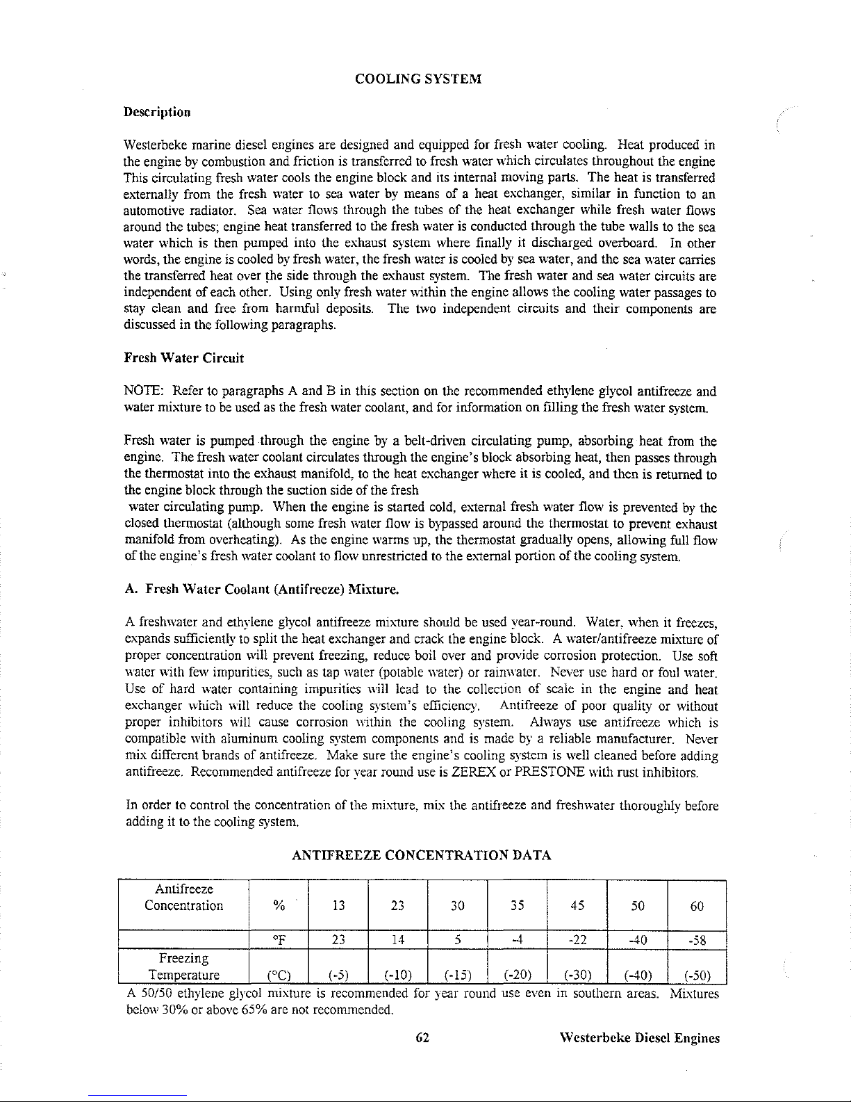
COOLING SYSTEM
Description
Westerbeke marine diesel engines are designed and equipped for fresh water cooling. Heat produced in
lbe engine
by
combustion and friction
is
transferred to fresh water which circulates lbroughout lbe engine
This circulating fresh water cools the engine block and its internal moving parts. The heat
is
transferred
externally from the fresh water to sea water
by
means
of
a heat exchanger, similar in function
to
an
automotive radiator. Sea water flows through the tubes
of
the heat exchanger while fresh water
flows
around lbe tubes; engine heat transferred to the fresh water
is
conducted lbrough the tube walls to lbe sea
water which is lben pumped into the exhaust system where finally it discharged overboard. In other
words, the engine
is
cooled
by
fresh water, the fresh water is cooled
by
sea water, and the sea water carries
lbe transferred heat over the side through the exhaust system. The fresh water and sea water circuits are
independent
of
each other. Using only fresh water within the engine allows the cooling water passages to
stay clean and free from harmful deposits. The two independent circuits and their components are
discussed in the following paragraphs.
Fresh
Water
Circuit
NOTE: Refer to paragraphs A and B in this section on the recommended ethylene glycol antifreeze and
water mi,,1ure to be used as the fresh water coolant, and for information on filling the fresh water system.
Fresh water
is
pumped through lbe engine
by
a belt-driven circulating pump, absorbing heat from lbe
engine. The fresh water coolant circulates lbrough the engine's block absorbing heat, then passes Jbrough
lbe lbermostat into the exhaust manifold,
to
lbe heat exchanger where it
is
cooled, and then is returned
to
lbe engine block through the suction side
of
the fresh
water circulating pump. When the engine
is
starred cold, external fresh water flow is prevented
by
lbe
closed lbermostat (allbough some fresh water flow
is
bypassed around lbe thermostat to prevent exhaust
manifold from overheating).
As
lbe engine warms up, the thermostat gradually opens, allowing full flow
of
the engine's fresh water coolant to flow unrestricted
to
the e,,1ernal porrion
of
the cooling system.
A.
Fresh
Water
Coolant (Antifreeze) Mixture.
A freshwater and ethylene glycol antifreeze mixture should be used year-round. Water, when it freezes,
expands sufficiently
to
split the heat exchanger and crack the engine block. A water/antifreeze mixture
of
proper concentration will prevent freezing, reduce boil over and provide corrosion protection.
Use
soft
water
"ith
few
impurities, such as tap water (potable water) or rainwater. Never use hard or
foul
water.
Use
of
hard water containing impurities will lead to the collection
of
scale in the engine and heat
exchanger which will reduce the cooling system's efficiency. Antifreeze
of
poor quality or without
proper inhibitors
''''ill
cause corrosion within the cooling system. Always use antifreeze which is
compatible with aluminum cooling system components and is made
by
a reliable manufacturer. Never
mix different brands
of
antifreeze. Make sure the engine's cooling system
is
well cleaned before adding
antifreeze. Recommended antifreeze for year round use
is
ZEREX or PRESTONE with rust inhibitors.
In order
to
control the concentration
of
the mixture, mix the antifreeze and freshwater thoroughly before
adding it
to
the cooling system.
ANTIFREEZE CONCENTRATION DATA
Antifreeze
Concentration
%
13
23
30
35 45
50
60
OF
23
14
5
-4 -22
-40
-58
Freezing
Temperature
eC)
( -5) (-10)
(-15)
(-20)
(-30)
(-40) (-50)
- -
A
)0/)0
ethylene glycol mIxture
IS
recommended for year round use even
III
southern areas. MIxtures
below
30%
or above 65% are not recommended.
62
Westerbeke
Diesel Engines
Page 69
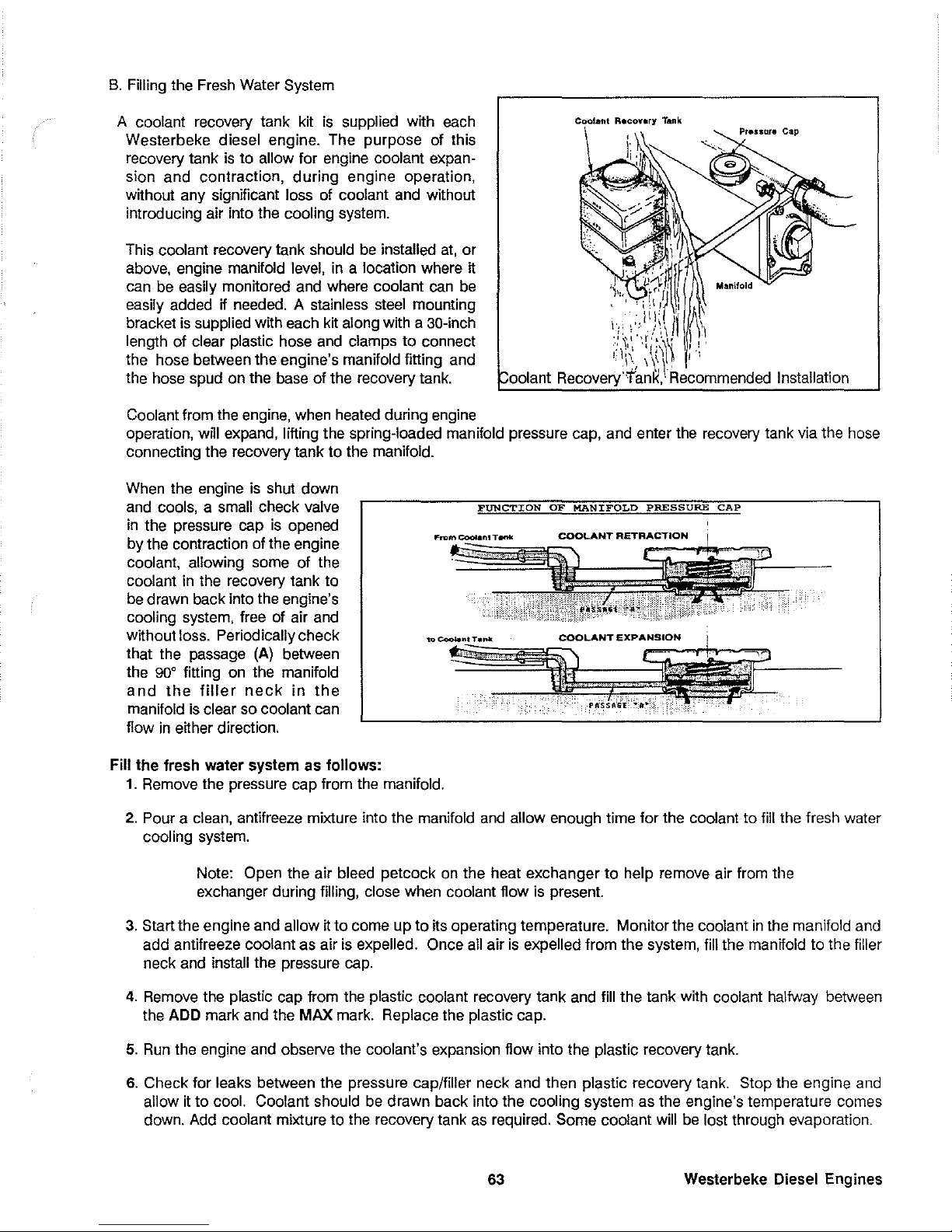
B.
Filling the Fresh Water System
A coolant recovery tank kit
is
supplied with each
Westerbeke diesel engine. The purpose of this
recovery tank
is
to
allow for engine coolant expan-
sion and contraction,
during
engine operation,
without any significant loss of coolant and without
introducing air into the cooling system.
This coolant recovery tank should
be
installed
at,
or
above, engine manifold level,
in
a location where
tt
can be easily monitored and where coolant can be
easily added if needed. A stainless steel mounting
bracket is supplied with each kit along with a 30-inch
length of clear plastic hose and clamps
to
connect
the hose between the engine's manifold fitting and
the hose spud on the base of the recovery tank.
Coolant from the engine, when heated during engine
operation,
wni
expand, lifting the spring-loaded manifold pressure cap, and enter the recovery tank via the hose
connecting the recovery tank to the manifold.
When the engine is shut down
and cools, a small check valve
in
the pressure cap is opened
by the contraction of the engine
coolant, allowing some of the
coolant
in
the recovery tank
to
be drawn back into the engine's
cooling system, free of air and
without loss. Periodically check
that the passage
(Al
between
the
900 fitting on the manifold
and
the
filler
neck
in
the
manifold is clear so coolant can
flow
in
etther direction.
Fill
the
fresh
water
system
as
follows:
1.
Remove the pressure cap from the manifold.
FUNCTION
OF MANIFOLD
PRESSURE
CAP
2.
Pour a clean, antifreeze mixture into the manifold and allow enough time for the coolant
to
fill
the fresh water
cooling system.
Note:
Open the air bleed petcock on the heat exchanger
to
help remove air from the
exchanger during filling, close when coolant flow is present.
3.
Start the engine and allow
tt
to
come up
to
tts
operating temperature. Monitor the coolant
in
the manifold and
add antifreeze coolant as air is expelled.
Once all air
is
expelled from the system, fill the manifold to the filler
neck and install the pressure cap.
4.
Remove the plastic cap from the plastic coolant recovery tank and fill the tank with coolant halfway between
the
ADD
mark and the
MAX
mark. Replace the plastic cap.
5.
Run
the engine and observe the coolant's expansion flow into the plastic recovery tank.
6.
Check for leaks between the pressure cap/filler neck and then plastic recovery tank. Stop the engine and
allow it
to
cool. Coolant should be drawn back into the cooling system as the engine's temperature comes
down. Add coolant mixture
to
the recovery tank
as
required. Some coolant will be lost through evaporation.
63
Westerbeke Diesel Engines
Page 70

Thermostat
Generally, thermostats are of two types.
One is simply a choking device which opens and closes as the engine's
temperature rises and falls.
The
second type
has
a bypass mechanism. Usually this
is
a disc
on
the bottom of the
thermostat which moves downward to close off
an
internal bypass passage within the head. Since
1980,
each type
of thermostat
has
a hole punched through
it.
The hole
is
a bypass to prevent the exhaust manifold from overheating
during the engine's warm-up. Replacement thermostats must have this design characteristic.
Sea
Water Circuit
The
sea
water flow
is
created by a positive dis-
placement, neoprene impeller pump.
The
pump
draws
sea
water directly from the ocean through
the
sea
cock
and
sea water strainer and passes
the water to the heat exchanger's sea water inlet.
The
sea
water
passes
through
the
heat
exchanger's tubes, absorbing heat from the fresh
water circulating around the tubes. The
sea
water
is
then discharged from the cooling system overboard through the water-injected wet exhaust system.
One
or two zinc pencil anodes are located
in
the
sea water cooling circuit within the heat exchanger. (Refer to your model's parts list for quan-
HEW
ANODE
REPLACE REPLACE
Zinc Anode Conditions
CLEAN
OR
REPLACE
tity.)
The
purpose of the zinc anode is to sacrrrice itself to electrolysis action taking place in the sea water cooling
circuit, thereby reducing the effects of electrolysis
on
other components of the system. The condition of the zinc
anode should be checked monthly and the anode cleaned or replaced as required.
Spare anodes should be
carried
on
board. Zinc anode debris should be cleaned from the area inside of the heat exchanger where the zinc
is
located. If this zinc debris
is
allowed to accumulate, it will block the tube openings through which the cooling sea
water should flow.
Raw Water Pump
The
raw water pump is a self-priming, rotary pump with a non-ferrous
housing and a neoprene impeller.
The impeller has flexible vanes
which wipe against a curved cam
plate within the impeller housing,
producing the pumping action.
On
no account should this pump be
run
dry. There should always be a
spare impeller and impeller cover
gasket aboard (an impeller kit).
Raw
water pump impeller failures
occur when lubricant (raw water) is
not present during engine operation.
Such failures are not warrant-
able,
and
the
operators
are
cautioned
to
make sure raw water
flow
is
present at start-up.
Westerbeke Diesel Engines
EYED
DftlYE
.HA~T
IIEOPJlEIlE
IIiPELLER
RAW
""ATER
PUMP
CURVED
CAlli
PLATE
64
aCPlEWDRIVER
1
....
ELLE"
COYEIII
GASKET
IIiPELLER
COV£R
Page 71
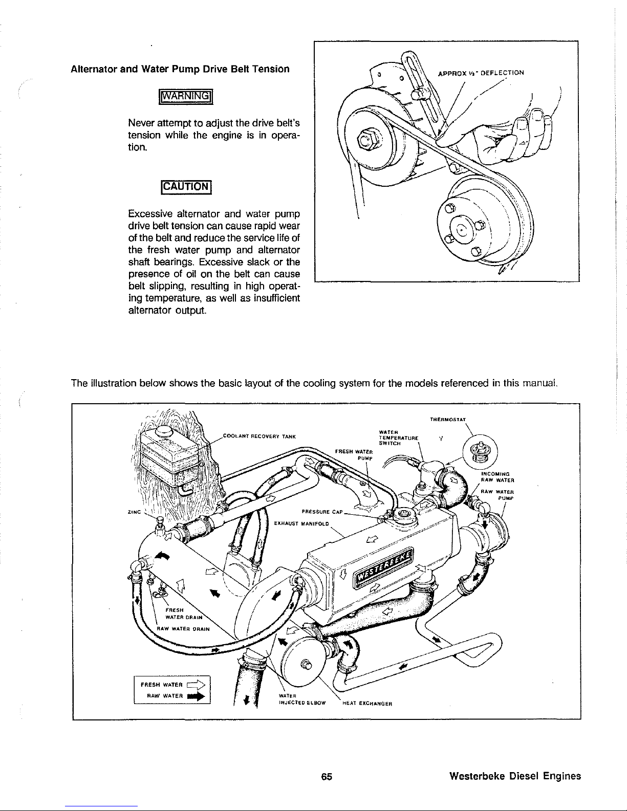
Alternator and Water Pump Drive Belt Tension
IIWARNINGU
Never attempt
to
adjust the drive belt's
tension while the engine
is
in
opera-
tion.
ICAUTIONI
Excessive alternator and water pump
drive
belt tension can cause rapid wear
of the
belt and
red
uce the service life of
the fresh water pump and
alternator
shaft bearings. Excessive slack
or
the
presence of oil on the
belt can cause
belt slipping, resulting
in
high operat-
ing temperature, as
well
as
insufficient
alternator output.
APPROX
Vt-
DEFL.ECTION
\
I
The illustration below shows the basic layout of the cooling system for the models referenced
in
this manual.
FRESH
WATER
~
RAW WATER
~
WATER
II'IJECTfD
f:l90W
65
WATER
TEMPERATURE
SWITCH
EXCHANGER
THERMOSTAT
./
Westerbeke Diesel Engines
Page 72
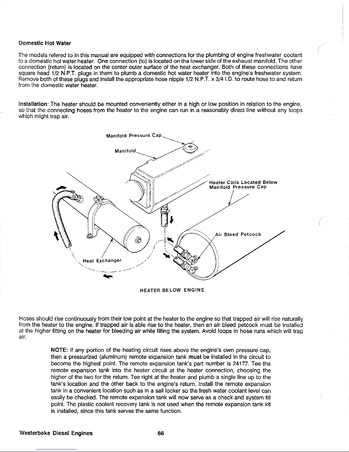
Domestic Hot Water
The models refered
to
in
this manual are equipped with connections for the plumbing of engine freshwater coolant
to a domestic hot water heater.
One connection (to) is located on the lower side of the exhaust manifold. The other
connection (return)
is
located
on
the center outer surface of the heat exchanger. Both of these connections
have
square head 1/2
N.P.T.
plugs
in
them
to
plumb a domestic hot water heater into the engine's freshwater system.
Remove both of these plugs and install the appropriate hose nipple 1/2 N.P.T. x
3/41.0.
to
route hose
to
and return
from the domestic water heater.
Installation: The heater should be mounted conveniently either
in
a high
or
low position
in
relation
to
the engine,
so
that the connecting hoses from the heater
to
the engine can run
in
a reasonably direct line without any loops
which might trap
air.
\
\
,
"Heat
Exchanger
.
-----.
--
-
---
..
,
~I·'
/
,~
, \
/ " .... I {
.....
/~
HEATER
BELOW
ENGINE
Air
Bleed
PetcQck
Hoses should rise continuously from their low point at the heater
to
the engine so that trapped air will rise naturally
from the heater
to
the engine. If trapped air is able rise
to
the heater, then an air bleed petcock must be installed
at the higher fitting on the heater for bleeding air while filling the system. Avoid loops
in
hose runs which will trap
air.
NOTE: If any portion of the heating circuit rises above the engine's own pressure cap,
then a pressurized (aluminum) remote expansion tank
must
be installed
in
the circuit
to
become the highest point. The remote expansion tank's part number
is
24177. Tee the
remote expansion tank into the heater circuit at the heater connection, choosing the
higher of the two for the return. Tee right at the heater and plumb a single line up
to
the
tank's location and the other back to the engine's return. Install the remote expansion
tank
in
a convenient location such
as
in a sail
locker so the fresh water coolant level can
easily
be
checked. The remote expansion tank will now serve
as
a check and system fill
point. The plastic coolant recovery tank is not used when the remote expansion tank kit
is installed, since this tank serves the same function.
Westerbeke Diesel Engines
66
Page 73

The pressure cap on the engine's manifold should be installed once the engine's cooling system is filled with
coolant. Finish filling the cooling system from the remote tank once the system is filled and is free of air and exhibits
good coolant circulation. During engine operation, checking the engine's coolant should
be
done at the remote
tank and not at the engine manifold cap.
The hose connection from the heater
to
the remote expansion tank should be routed and supported
so
as
to
rise
continuously from the heater
to
the tank, enabling any air
in
the system
to
rise.
\
NOTE:
An
air bleed petcock is located at the top center
of
the engine's heat exchanger.
Open this petcock when filling the freshwater system
to
allow air
in
the exchanger
to
escape. Close tightly once all air is removed.
'~eat
Exchanger
Pressu
re
Cap
is
Rated Lower
than
Manifold
Cap
Metal
Remote
Tank
(Kil#024177)
Heater
Coils Located
Above
Manifold Pressure
Cap
HEATER
ABOVE
ENGINE
67
Westerbeke Diesel
Engines
Page 74

LUBRICATION SYSTEM
Engine Oil
For engine lubrication. use lubricating oil designated
for
diesel service. These oils are classified according
to
the
API
specifications into service grades
CA. CB.
CC and
CD.
The use
of
CC
or
higher (CD) grades. made by well-known
manufacturers
is
recommended. The oil selected should be used thereafter.
Engine Oil
Viscosity
(SAE
Number)
Use
an
oil having a viscosity best suited
to
the atmospheric temperature. Use of an all-season oil
SAE
10W-30 with
minimum viscosity change under different temperatures
is
suggested.
Atmospheric Temperature
600 F (20
0
C)
or
higher
400 F
(50
C)
- 60
0
F (20
0
C)
400 F(5°
C)
-
or
lower
Viscosity
SAE
30
or 10W-30
SAE
20
or 10W-30
SAE
10W-30
NOTE: Do not use an engine lubricating oil with an
SAE
number greater than
30
in
the
engine.
Oil Pressure
The oil pressure during operation
of
the engine is indicated
by
the oil pressure gauge on the Admiral Panel.
During normal operation. the oil pressure will range between
30
and
60
psi.
At
idle speed. the oil pressure will range
between 15 and
30
psi. At the time of cranking. the oil pressure will rise proportionately with speed.
NOTE: A newly started. cold engine can have
an
oil pressure reading upwards of
60
psi.
A warmed engine can have an oil pressure reading as
low
as
15
psi. These readings may
also vary depending upon the speed at which the engine is running.
Westerbeke Diesel
Engines
68
Page 75

Engine Oil Change (to include filter)
1.
Draining the Oil Sump
Remove the oil drain hose from its attachment bracket
and
lower it into a container and allow the oil to drain, or attach a
pump to the end of the drain hose and pump the old oil out.
Make sure the oil drain hose is properly secured
in
its holder
after all of the old oil has
been
drained.
Always observe the
old oil as it
is
removed. A yellow/gray
emulsion indicates the presence of water
in
the oil. Although
this condition is
rare,
it does require prompt attention to prevent
serious damage.
Call
a competent mechanic should water be
present
in
the oil.
Raw
water present
in
the oil
can
be the result
of a fault
in
the exhaust system attached to the engine and/or
a siphoning through the raw water cooling circuit into the
exhaust, filling it up into the engine.
2.
Replacement of the Oil Filter
When removing the used oil filter, you may find it helpful and
cleaner to punch a
hole
in
the upper and lower portion of the
old filter to drain the oil from it into a container before removing
it.
This helps to lessen spillage. An automotive filter wrench
should be helpful
in
removing the old oil filter. Place some paper
towels and a plastic bag around the filter when unscrewing
it
to catch any oil left in the filter.
(Oil
or any other fluid
on
the
engine reduces the engine's
cooling ability.
Please
keep your
engine clean.) Inspect the old oil filter
as
it is removed to make
sure that the rubber
sealing gasket came off with the old oil
filter. If this rubber sealing gasket remains sealed against the
engine block, gently remove
it.
The replaceable cartridge-type
oil filter requires no cleaning inside, so
it may be properly
disposed
of.
When installing the new oil filter element, wipe the
filter gasket's
sealing surface on the engine block free of oil
and
apply a thin coat of clean engine oil to the rubber gasket
on
the oil filter. Screw the filter onto the threaded oil
filter stub, and then tighten the filter firmly by hand.
NOTE: Generic filters are not recommended,
as
the material standards or diameters of
important items
on
generic parts might
be
entirely different from genuine parts. Immedi-
ately
after an oil filter change and oil fill, run the engine for a few minutes to make sure
the oil pressure
is
normal and that there are no oil
leaks around the new oil filter.
3.
Filling the
Oil
Sump
Add fresh oil through the oil filler cap
on
the valve cover (refer
to the photos at the beginning of this manual for
filler cap
location
on
your unit and lube oil dipstick). After refilling the
oil, run the engine for a few moments while checking the
engine's oil pressure. Make sure there
is
no leakage around
the new oil filter or from the oil drain system,
and
then stop the
engine. Then check the quantity of oil with the
lube oil dipstick.
Fill
to, but not over, the high mark on the dipstick, should the
engine require additional
oil.
69
Top
Oil
Fill
--,..,..."
Rocker
((lver
_~-
Side [Jil
Fill
----'\>0:,.1
Oil
Dip&ticJc
----r-
--
Oil
lower
li.i
t.,..r
::-:--
--:
'._
Crankcase
Westerbeke Diesel Engines
Page 76
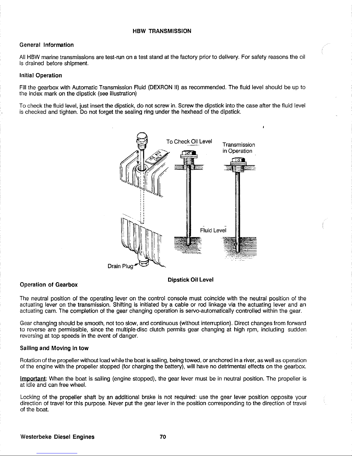
HBW TRANSMISSION
General Information
All
HBW
marine transmissions are test-run on a test stand at the factory prior
to
delivery. For safety reasons the oil
is
drained before shipment.
Initial Operation
Fill
the gearbox with Automatic Transmission Fluid
(DEXRON
II)
as
recommended. The fluid level should be up
to
the index mark on the dipstick
(see
illustration)
To check the fluid level, just insert the dipstick,
do
not screw in. Screw the dipstick into the case after the fluid level
is
checked and tighten. Do not forget the sealing ring under the hexhead of the dipstick.
Operation
of
Gearbox
To
Check Oil
Level
-<!'-
~
..
~
Transmission
in
Operation .
,
,
,
,
,
,
, ,
: '
, ,
-'u
Drain Plug
.....
Fluid Level
Dipstick
Oil Level
The
neutral position of the operating lever on the control console must coincide with the neutral position of the
actuating lever on the transmission. Shifting
is
initiated by a cable
or
rod linkage via the actuating lever and an
actuating cam. The completion of the gear changing operation
is
servo-automatically controlled within the gear.
Gear changing should be smooth, not too slow, and continuous (without interruption). Direct changes from forward
to reverse are permissible, since the
multiple.<Jisc clutch permits gear changing at high rpm, including sudden
reversing at
top
speeds
in
the event of danger.
Sailing and Moving
in
tow
Rotation of the propeller without load while the boat
is
sailing, being towed, or anchored
in
a river, as well
as
operation
of the engine with the
propeller stopped (for charging the battery), will have no detrimental effects on the gearbox.
Important: When the boat is sailing (engine stopped), the gear lever must
be
in
neutral position. The propeller
is
at
idle and can free wheel.
Locking of the
propeller shaft by an additional brake
is
not required: use the gear lever position opposite your
direction of travel for this purpose. Never put the gear lever
in
the position corresponding
to
the direction of travel
of the boat.
Westerbeke Diesel Engines
70
Page 77
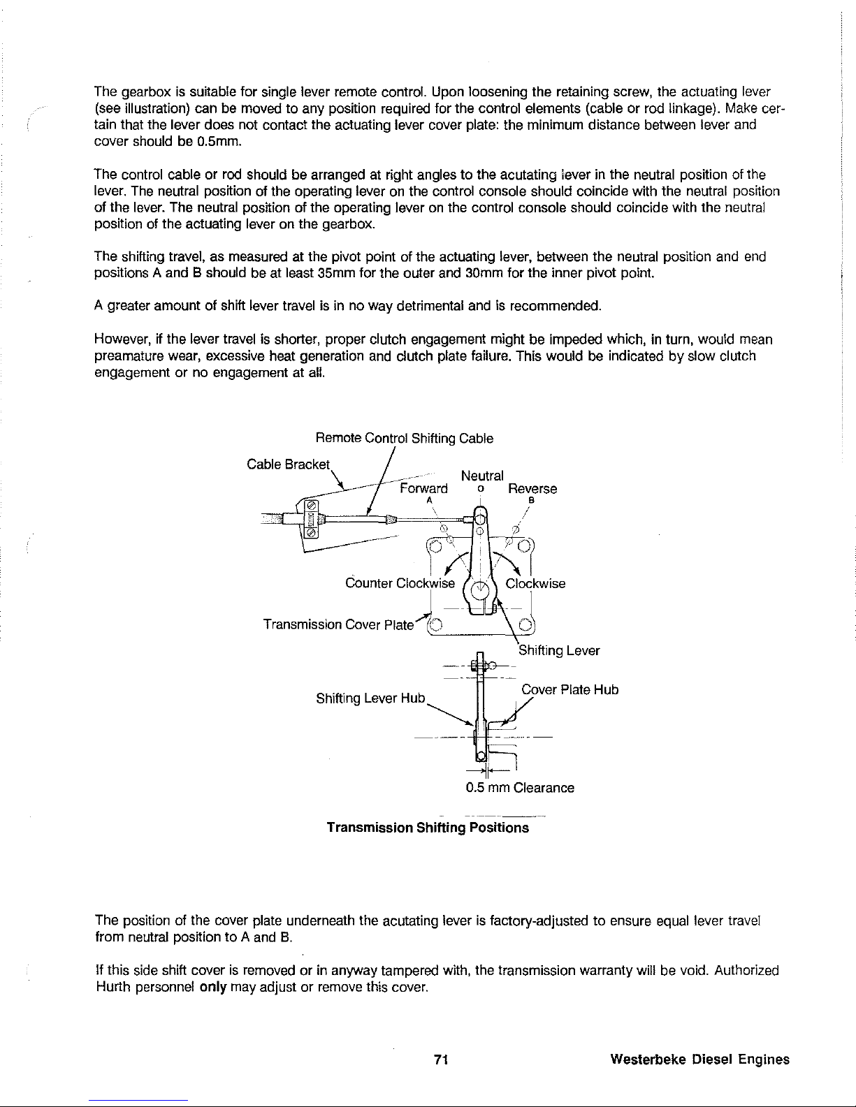
The gearbox
is
suitable for single lever remote control. Upon loosening the retaining screw, the actuating lever
(see illustration) can be moved
to
any position required for the control elements (cable or rod linkage). Make cer-
tain that the
lever does not contact the actuating lever cover plate: the minimum distance between lever and
cover should be
O.5mm.
The control cable
or
rod should be arranged at right angles
to
the acutating lever in the neutral position of the
lever. The neutral position of the operating
lever on the control console should coincide with the neutral position
of the lever. The neutral position of the operating
lever on the control console should coincide with the neutral
position of the actuating
lever on the gearbox.
The shifting travel, as measured at the pivot
pOint of the actuating lever, between the neutral position and
end
positions A and B should be at least 35mm for the outer and 30mm for the inner pivot point.
A greater amount of shift
lever travel
is
in no way detrimental and is recommended.
However,
if the lever travel is shorter, proper clutch engagement might be impeded which, in turn, would mean
preamature wear, excessive heat generation and clutch
plate failure. This would be indicated
by
slow clutch
engagement
or
no engagement at all.
Remote Control Shifting
Cable
Cable
Bracket
..
-.
. Neutral
Forward
0 Reverse
A B
\ /
Transmission Cover Plate 0 0
Shifting Lever
Shifting Lever Hub
Cover
Plate Hub
~,
Transmission Shifting Positions
The position of the cover
plate underneath the acutating lever
is
factory-adjusted
to
ensure equal lever travel
from neutral position
to
A and
B.
If this side shift cover
is
removed
or
in anyway tampered with, the transmission warranty will be void. Authorized
Hurth personnel
only
may adjust
or
remove this cover.
71
Westerbeke Diesel Engines
Page 78
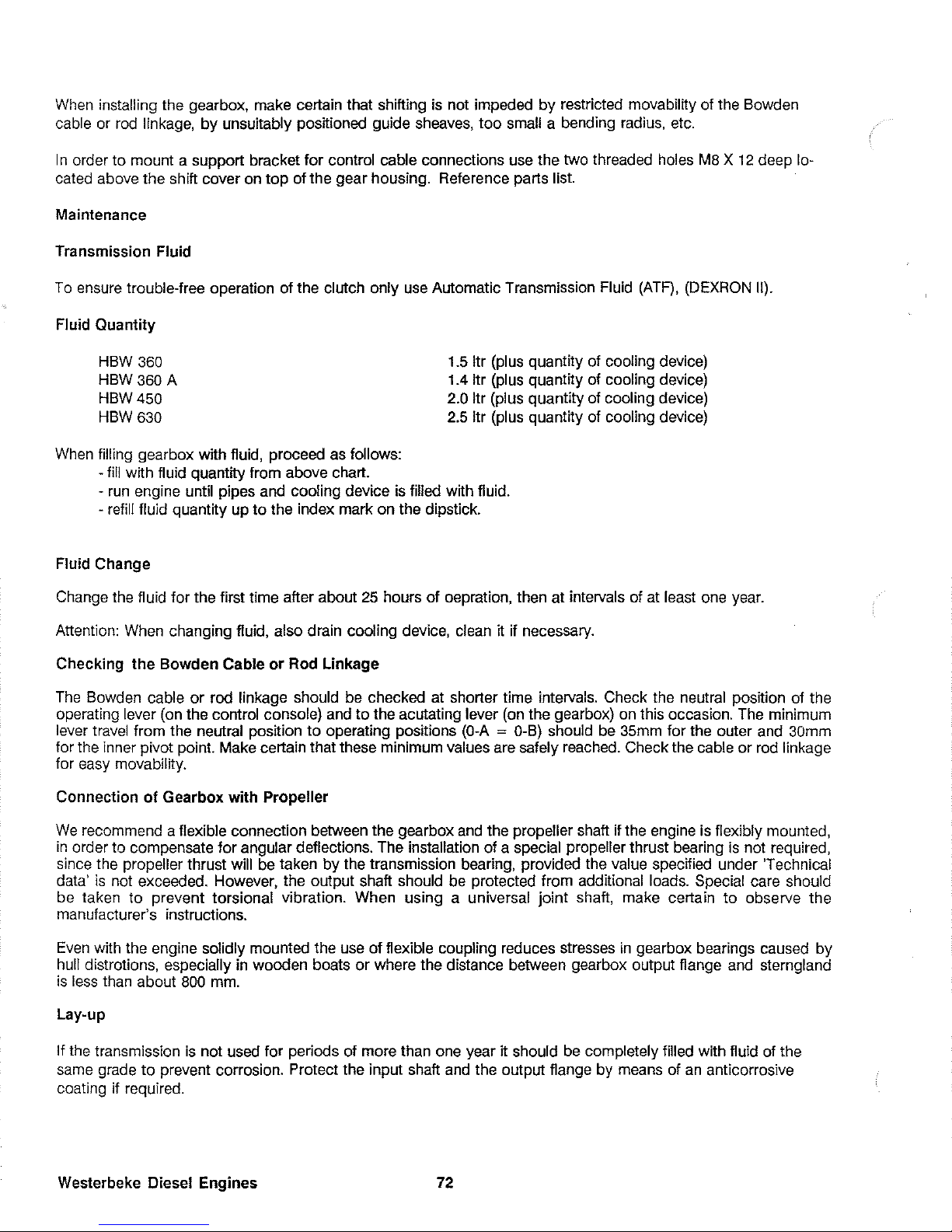
When installing the gearbox, make certain that shifting
is
not impeded
by
restricted movability of the Bowden
cable or rod linkage,
by
unsuitably posITioned guide sheaves,
too
small a bending radius, etc.
I n order to mount a support bracket for control cable connections use the two threaded holes
M8 X 12
deep lo-
cated above the shift cover on
top
of the gear housing. Reference parts list.
Maintenance
Transmission Fluid
To
ensure trouble-free operation of the clutch only use Automatic Transmission Fluid
(ATF)
, (DEXRON II).
Fluid Quantity
HBW
360
HBW 360 A
HBW
450
HBW
630
When filling gearbox with fluid, proceed as follows:
- fill with fluid quantity from above chart.
1.5
Itr (plus quantity of cooling device)
1.4
Itr (plus quantity of cooling device)
2.0 Itr (plus quantity of cooling device)
2.5
Itr (plus quantity of cooling device)
-
run
engine until pipes and cooling device is filled with fluid.
-
refill fluid quantity up
to
the index mark on the dipstick.
Fluid Change
Change the fluid for the first time after about 25 hours of oepration, then at intervals of at least one year.
Attention: When changing fluid,
also drain cooling device, clean it if necessary.
Checking
the
Bowden
Cable
or
Rod Linkage
The
Bowden cable
or
rod linkage should be checked at shorter time intervals. Check the neutral position of the
operating lever (on the control console) and
to
the acutating lever (on the gearbox) on this occasion. The minimum
lever travel from the
neutral
pOSITion
to
operating
pOSITions
(O-A = O-B)
should be 35mm for the outer and 30mm
for the inner pivot point. Make certain that these minimum values are safely reached. Check the cable
or
rod linkage
for easy movability.
Connection
of
Gearbox
with
Propeller
We
recommend a flexible connection between the gearbox and the propeller shaft if the engine is flexibly mounted,
in
order to compensate for angular deflections. The installation of a special propeller thrust bearing
is
not required,
since the
propeller thrust will be taken
by
the transmission bearing, provided the value specified under Technical
data'
is
not exceeded. However, the output shaft should be protected from additional loads. Special care should
be taken to prevent torsional vibration. When using a universal joint shaft, make certain
to
observe the
manufacturer's instructions.
Even
with the engine solidly mounted the use of flexible coupling reduces stresses
in
gearbox bearings caused by
hull distrotions, especially in wooden boats
or
where the distance between gearbox output flange and sterngland
is
less than about
800
mm.
Lay-up
If the transmission
is
not used for periods of more than one year
IT
should be completely filled with fluid of the
same grade
to
prevent corrosion. Protect the input shaft and the output flange by means of
an
anticorrosive
coating if required.
Westerbeke
Diesel Engines
72
Page 79
HSW
TRANSMISSION
1. Operation
All HSW transmissions have been submitted
to
a test run before shipment.
In
normal operation, the transmission should only be shifted with the engine at idle speed. In emergency
eases it is also admissible to shift at higher speeds.
Optimum effectiveness
of
fluid
can
only be assured
if
fluid and filter are changed regularly according
to
maintenance schedule.
Visual checks for leakage should be made from time to time.
I WARNING I
Work
on the transmission must only be peIiormed with the engine and propeller
at
standstill.
II
CAUTION
II
Before the first stali-up, the transmission must be filled with transmission fluid.
For filling procedure, fluid type, quantity and level refer pages 76 - 78.
II
CAUTION
II
Using the transmission with
an
insufficient oil lc,'cl will damage the gears. An excessive oil level
may cause leakage at the shaft seals and transmission breather, and raise the operating temperature
considerably.
73
Westerbeke Diesel Engines
Page 80

2.
Operation Procedure
II
CAUTION
II
Before operating the transmission, check fluid level. In
normal
operation, the transmission should only be shifted
with the engine at idle speed. Shifting at higher engine
speed may lead to overstress
of
the friction linings
of
the
coupling
and
flywheel
damper
plate
and
should be avoided
in normal operation.
NOTE: The transmission may be shifted from forward
to
reverse in case
of
emergency even up
to
an
engine speed
of
3200 rpm. The transmission is shifted
by
actuating the shifting lever (figure IV-I, item I)
at
the control block (figure IV-I, item
2).
Shifting positions:
A
~
Propeller rotation Right Hand.
N
~
Neutral position
B
~
Propeller rotation Left Hand
I
WARNING
I
Stali
engine with transmission in neutnll only.
The operating temperature
of
the
transmission
should not exceed 176° F (80°C).
A connection for a temperature probe has been
provided. At maximum output
of
the engine,
the
fluid temperature may reach 220°F (105°C).
II
CAUTION
II
If
the fluid temperature is too high, stop engine
immediately and chcck transmission fluid level
and oil cooler for propcr water flow. Do not
stmi
the
engine again until the malfunction is
eliminated.
Wcsterbeke Diesel Engines
74
'2
\
1
Rgure
IV·1
Page 81

2.1 Moving
in
tow or anchoring
When the boat moves in tow or is anchored, the
propeller may turn with the water current This
represents no danger for the transmission.
In
a boat
with two engines, the propeller
of
the unused
transmission may idle freely, When the engine is
off, the position
of
the shifting lever is irrelevant.
I
WARNING
I
• Do not work
on
the transmission when being
towed, or anchoring
in
a river because the
propeller may rotate.
• Do not work on the transmission
in
a twin
engine boat, when one unit is
under
(lOWer.
The
propeller
shaft
of
the
inoperative
transmission will rotate.
• When the engine runs
at
idle, (such as when
charging
the
battery
with
the
alternator),
the
shifting lever (figure IV-3, item
1)
must
be
held in
the
neutral
position (N) to prevent
the
boat from moving.
Figure
lV-3
75
l
!
,
~//
///
~
..
///
..
,"'
..
,,~
'~.~~~.
.......
~'.
~
..
Figure
!V-2
Westerbel<e Diesel Engines
Page 82

MAINTENANCE
HSW
TRANSMISSION
I
WARNING
I
Do not work
on
transmission when engine and
propeller are running. Always
wear
gloves when
working on a hot transmission.
1.
Fluid level check.
Transmission fluid level can be checked
in
a cold or
a hot condition.
Always
check
fluid level before
operating
transmission.
1.1
Loosen fluid dipstick (figure VI-I, item
1)
by turning
the handle counterclockwise.
1.2 Wipe dipstick with a clean and dustfree cloth.
1.3
Insert dipstick
to
its stop. Remove dipstick and check
fluid level again.
NOTE: Quantity of fluid level between minimum and
maximum marks is 0.53 US-qts. (0.5 liters).
1.4 Insert the dipstick to its stop and lock it in place by
turning the handle clockwise.
II
CAUTION
II
Depending on the type and arrangement
of
the cooler
and
hoses, a cCliain
amount
of fluid will remain
in
these
after stopping the engine and may flow back into the
transmission after a long
period
of
non-usc. This may
cause
the
fluid level in
the
transmission to exceed
the
max. mark. Do not
rcmO\"c
this surplus fluid but
proceed
according
to steps 1.5
and
1.6.
1.5 Let engine rnn at idle speed with shifting lever
in
neutral position until fluid cooler and all pipelines are filled
with fluid.
1.6 Stop the engine and check fluid level again.
If
necessary, top fluid level up to the dipstick max. mark. The
fluid level on the dipstick (figure V-2. item 1) should be
between the min. and max. marks. The fluid levels should
be checked again after a short period of vessel use.
Wcstcrbckc Diesel Engines
76
Rgure
V~l
,.---~~~~--~~-.---~
'---
___________
J
Figure
V~2
Page 83
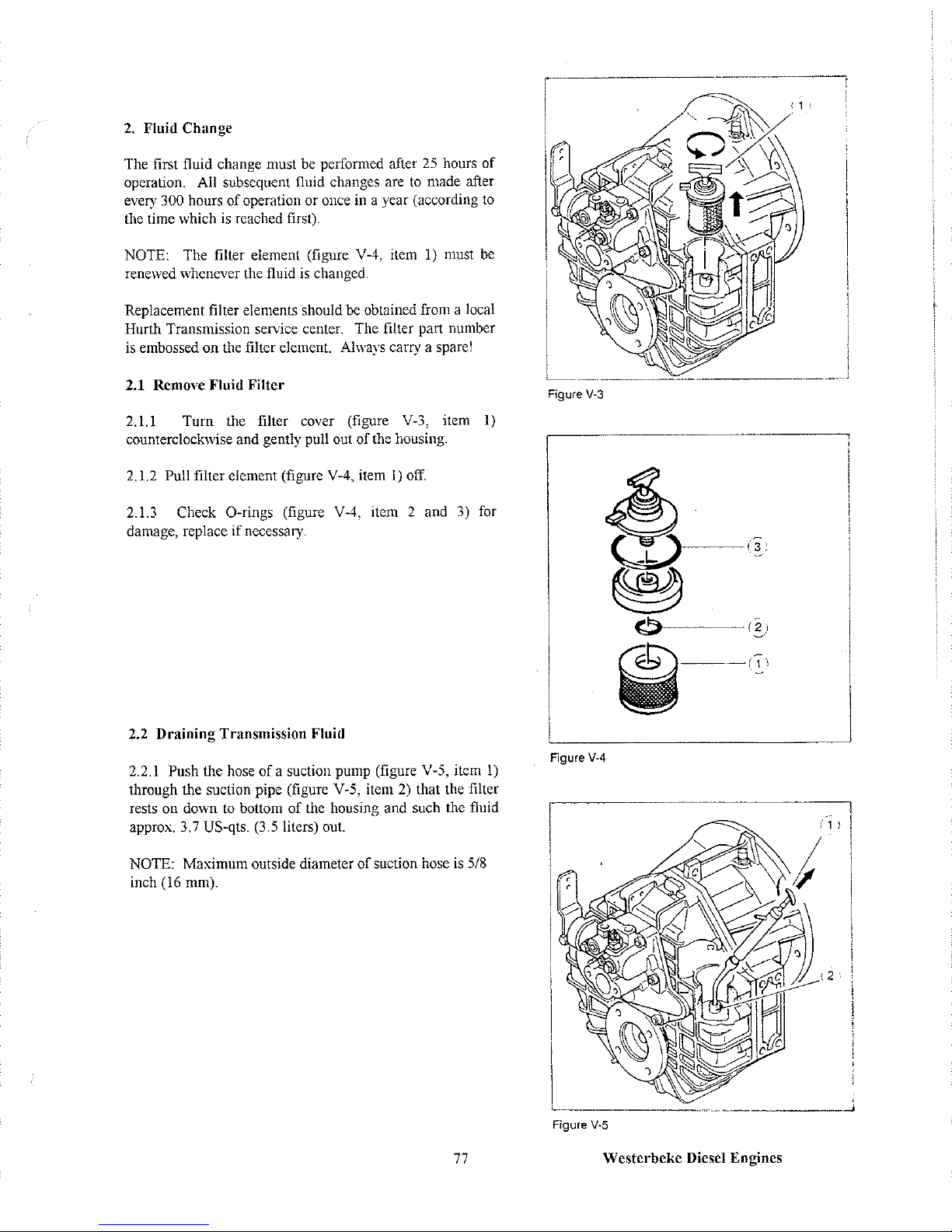
2.
Fluid
Change
The first fluid change must be performed after
25
hours
of
operation. All subsequent fluid changes are to made after
every
300 hours
of
operation or once in a year (according to
the time which is reached first).
NOTE: The filter element (figure V-4, item
1)
must be
rene\ved whenever the fluid is changed.
Replacement filter elements should be obtained from a local
Hurth Transmission service center. The filter part number
is embossed
on
the filter element. Always carry a spare!
2.1 Remove Fluid
Filter
2.1.1
Turn
the filter cover (figure V-3, item
1)
counterclockwise and gently pull out
of
the housing.
2.1.2
Pull filter element (figure V-4, item
1)
off.
2.1.3
Check
a-rings
(figure V-4, item 2 and 3) for
damage, replace if necessary.
2.2 Draining Transmission
Fluid
2.2.1 Push the hose
ofa
suction pump (figure V-5, item
1)
through the suction pipe (figure V-5, item
2)
that the filter
rests on down to bottom
of
the housing and such the fluid
approx. 3.7 US-qts. (3.5 liters) out.
NOTE: Maximum outside diameter
of
suction hose
is
5/8
inch (16
0101).
77
Figure
V-3
Figure
V-4
Figure V-5
Westerbeke
Diesel
Engines
Page 84

2.3 Filling
the
Transmission Fluid
2.3.1 Fill with 3.7 US-qts. (3.5 liters)
of
Automatic
Transmission Fluid (ATF) or Dexron
II
figure
6.
and add
the amount required for cooler and hoses.
II
CAUTION
II
Only use automatic transmission fluid such as
Dexron II-D,
or
Ford M2C-33G.
2.4 Inscrt fluid filter into housing
2.4.1 Place new filter element onto cover.
2.4.2 Lock filter cover
in
place
by
turning
clockwise.
Figure V-7
The fluid level should be checked again after a short
period
of
running.
3.0
Trial
Run
3.1 Carry out a trial run after the fluid change.
3.2 Set shifting lever
to
neutral position
(N).
Start
the engine and let it run idle for a short time to fill
the cooler and hoses with transmission fluid.
3.3 Stop the engine and check fluid level again. If
necessary. add additional fluid
to
bring the level
to
the max. mark. Do not over filii
The fluid level
on
the dipstick (figure V-2, item I)
should be between the min. and max. marks. The
fluid level should be checked again after a short
period
of
operation.
4.0 Storage
If
the transmission
is
stored for a long period
of
time
12
months or more, it should be topped up with fluid
through the dipstick hole
to
prevent the unit from the
unit
from
corroding
on
the
inside.
II
CAUTION
II
Reduce
the
fluid to the
proper
level when putting
the unit back into sen'ice again.
Wcsterbckc Diesel Engines
78
Figure
V-6
L
Figure
V-7
I
I
i
I
,
i
Page 85

Borg Warncr Transmission
OI)Cl'ation
Perform all pre-operation maintenance on the Velvet Drive transmission. (Page 82)
At the helm place the transmission selector control in Neutral before starting engine.
Shifting from one
selector position
to
another selector position may be made at any time below 1000 rpm and in any order.
Shifts should be made at the lowest practical engine speed.
Too low
of
an idle speed will produce a chattering noise from the gear and damper plate. In such cases
idle speed should be increased.
II
CAUTION
II
Shifting above 1000 rpm can severely damage boat, transmission and engine.
a.
Neutral - Move selector lever to the middle position. You should feel the detent center the shift
lever on the transmission through the linkage
to
the selector lever. With the control in this position,
hydraulic power is completely interrupted and the output shaft
of
the transmission does not turn.
b.
Fonvard - Move selector lever
to
the fonvard position. You should feel the detent. The shift lever
on the transmission is in the
fomard
position. The output shaft and the propeller should move the
boat
in a forward
direction.
WARNING
If
boat moves backwards with the selector control in the fonvard position, shut
off engine.
NOTE: This problem can be a result
of
improper installation
by
the boat
builder or service facility.
II
CAUTION
II
Vcrs earl,y gear failurc will occur when the transmission is operated in
reverse
to
obtain for'ward motion.
c.
Rev-erse - Move selector lever to the reverse position. You should feel the detent. The shift lever
on the transmission is in the reverse position. The output shaft and the propeller should move the
boat in a reverse direction. (Astern).
Velvet Drive Transmission Operation
a.
Place selector control in the Neutral position. (Neutral Safety Switch Closes)
b.
Start
engine
and
set
throttle
at
idle
speed
and
warm
up
transmission
oil
for a few
minutes.
C.
Be
aware
of
any
unusual
noises
or
\-;brations
and
investigate
to
determine
the
cause.
79 Westerbeke Diesel Engines
Page 86

II
CAUTION
II
Before checking oil, shut off engine. Hot oil could cause burns.
d.
Shut off engine and check transmission oil level and add oil,
if
required, to the full mark on the
dipstick.
e.
Restart engine.
Westerbeke Diesel Engines
80
Page 87
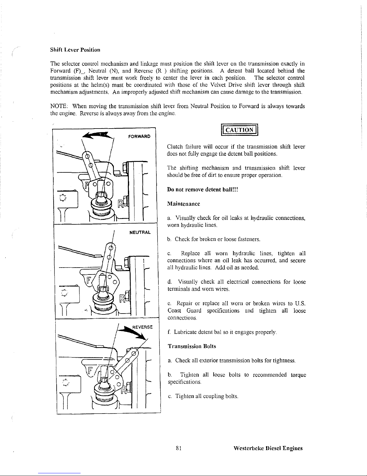
Shift Lever Position
The selector control mechanism and linkage must position the shift lever on the transmission exactly
in
Forward
(FL
Neutral (N), and Reverse (R ) shifting positions. A detent ball located behind the
transmission shift lever must
work
freely
to
center the lever in each position. The selector control
positions at the helm(s) must
be
coordinated with those of the Velvet Drive shift lever through shift
mechanism adjustments. An improperly adjusted shift mechanism can cause damage to the transmission.
NOTE: When moving the transmission shift lever from Neutral Position
to
Fonvard
is
always towards
the
engine.
Reverse
is
always
away
from
the
engine.
FORWARD
II
CAUTION
II
Clutch failure will occur if the transmission shift lever
does
not
fully
engage the detent ball positions.
The shifting mechanism and transmission shift lever
should
be
free of dirt to ensure proper operation.
Do not remove detent ball!!!
Maintenance
a.
Visually check
for
oil leaks
at
hydraulic connections,
worn hydraulic lines.
b.
Check for broken or loose fasteners.
c.
Replace all worn hydraulic lines, tighten all
connections where
an
oil leak
has
occurred,
and
secure
all hydraulic lines. Add oil
as
needed.
d.
Visually check all electrical connections
for
loose
terminals
and
\\.'orn
wires.
e.
Repair or replace all worn or broken wires to
U.S.
Coast Guard specifications and tighten all loose
connections.
f.
Lubricate detent bal
so
it engages properly.
Transmission Bolts
a.
Check all exterior transmission bolts for tightness.
b.
Tighten all loose bolts
to
recommended torque
specifications.
c.
Tighten all coupling bolts.
81
Westerbeke Diesel Engines
Page 88

Change
Transmission Oil
A seasonal transmission oil change is recommended for all pleasure boats. Work boats require
tranmsission oil changes every
1,000 hours. Oil must be changed anytime it becomes contaminated,
changes color, or becomes rancid smelling.
OIL FILLER CAP
AND
DIPSTICK
ASSEMBLY
HOLE
Shift
Lever
From
Cooler
,
-l----
FULL
... MARK
Dipstick
Assembly
,
10-13110-14
Westerbckc
Diesel Engines
WARNING
Do not use gasoline or any other volatile or highly
combustible liquid as a solvent.
Removing Transmission
Oil (Oil Filler Cap)
a.
Place an appropriate size container near oil cooler
return line.
b.
Remove oil filler cap and dipstick assembly.
C.
Remove oil cooler return line.
d.
Allow oil from return line to drain into container.
e.
Connect oil cooler return line and torque to 25-35 ft.-
Ibs. (34-47
Nom).
f.
Use a suction pump
in
the oil filler cap hole to remove
remaining oil in the tranmsission.
g.
Remove suction pump from transmission.
Fill Tranmsission
With
Oil
The quantity
of
oil depends upon the model Velvet Drive
angle
of
installation and oil cooling system capacity.
a.
Using a suitable transmission oil (see Recommended
Transmission
Oil Table below), fill transmission through
dipstick hole until oil reaches full mark on dipstick.
b.
Replace oil filler cap and dipstick assembly in hole.
Press to bottom and turn clockwise until finger tight.
II
CAUTION
II
Before running engine replace oil filler cap and dipstick
assembly. Hot oil expelled through the dipstick hole
during operation
of
the gear could cause burns.
c.
Connect battery and run engine to fill oil cooling
system. With engine off promptly recheck oil with
dipstick and fill as required.
82
Page 89

Recommended Transmission Oil
Oil
+
Dextron II, Type F
Transmission Fluid *
SAE #30 *
SAE #40 *
Mnlti-Viscosity Oil
Conditions
Recommended
Recommended
Preferred
**
Acceptable
**
(High Temperature Only)
Not Acceptable
* Detroit Diesel Anision Type
C3
Specification
**
Detroit Diesel Anision Type
C3
Specification, Engine Speed Below 3,000 rpm.
+ SAE - API Service Class CD Recommended, Class C Acceptable
Pre-operation
Pre-operation Maintenance
is
a precaution against a potentiany costly major overhauL The pre-operation
maintenance procedure needs to be completed on a daily basis before starting engine.
a.
Check transmission oil level on dipstick before operation. Add suitable oil as required.
b.
Check for oil leakage in the ben housing, output shaft and other gasket sealed areas.
c.
Visually check
the
general
condition of
the
transmission
and
wipe
clean.
During operation,
be
aware
of
any
unusual
noises
or
vibrations
and
investigate
to
determine
the
cause.
HCAUTION
II
System related noises
or
vibrations can occur at low engine speeds which can cause gear
rattIe
resulting in damage to the boat engine and/or transmission. Warner Gear is not responsible for
total system related torsional vibration
of
this type.
Oil temperature maximum
is
190°F (105°C) during operation. A transmission warning light (optional)
will inuminate
if
oil temperature is too high. Should this occur, check transmission level or consult your
nearest Velvet Drive distributor.
II
CAUTION
II
If
drainback occurs, oil level must be compensated. To correct this, see your authorized Velve
Drive transmission service facility.
83
Westerbeke
Diesel Engines
Page 90

Service
manuals
can
be
obtained
by
contacting
the
nearest
Velvet
Drive
distributor.
Warranty Note: Gear failures the result
of
shock leads.
Reference Westerbeke
Service Bulletin #142
Dated
12
September 1984
Borg Warner is aware of the shock loads that can be placed on it's gears the result
of
mechanical propeller operation with opening or fully reversing
of
propeller blades while
shifting. Therefore torque loads and directional changes should
be
made at low engine
speeds.
Borg
Warner
reserves
the
right
to
make a determination
as
to
cause
of
failure
of
its
gear
involving a
warranty
claim.
If
it is found that the failure was caused
by
a shock load, the warranty claim will be denied.
Lay-up
Storage requires special care. Before winter storage one must:
a.
Disconnect the battery.
b.
Drain
water
from
the
transmission
oil
cooling
system.
c.
Wipe transmission free
of
dirt, grime and grease.
d.
Touch
up
unpainted
areas
of
the
transmission
using
suitable
paint.
e.
Loosen attaching hardware from transmission output flange and propeller shaft coupling flange before
removing
boat
from
water
and
separate
flanges.
TRANSMISSION CONNECTION & REFERENCE POINTS
Shift Lever
From Cooler
Westerbel{c Diesel Engines
Di~)sti(:k
Assembly
10-13/10-14
84
From Cooler
(2.10: 1 Only)
From Cooler
(Except2.10:1)
10-17/10-18
Page 91

Walter V-Drives
Operation
A pressure drop warning light
is
mounted
on
the
instrumeut panel on V-drives equipped with an oil
circulating pump. The warning light will sta
on
until the
boat gets under way
and
the
engine speed increases
to
sufficient RPM for the pump
to
maintain pressure. This
normally occurs at approximately
1200
RPM,
but the
actual speed may vary
by
as much as 400 rpm. Extended
cruising at
low
rpm, such as when trolling,
is
not
harmful to the V -drive, even though the warning light
may stay lit. Normal operation is between 6
ro
12
psi.
The light will
go
on when the oil pressure drops below 2
psi. Loss
of
oil andlor insufficient oil level are the major
causes
of
pressure drop. The oil level should
immediately
be
restored,
and
while running the
boat,
the
unit should
be
checked for leaks.
If
the oil level
is
normal
and
the light stays lit when
the
boat
reaches
normal cruising speed, the wiring should
be
checked for
loose andlor corroded connections. If the wiring
is
correct and the light remains lit, the #49 pressure drop
switch, which
is
mounted on the side of the V-drive (see
illustration), should be checked for proper operation.
*49
PRE'SSIURE'..1
DROP SWITCH
WATER
The switch can easily be removed and an accurate oil pressure gauge installed in its place.
If
the pressure
is normal, the switch should be replaced.
If
the pressure
is
below normal, the oil lines should be checked
for blockage. The pump
is
standard on the RV-48 and an optional feature on other models (not available
on the RV-IO).
The oil level should be checked several times during the season, especially on V -drives without pumps
(see Oil Fill).
A clatter or rattle in the V-drive at
low
rpm
is
due
to
the overriding
of
the propeller during the
compression stroke of the engine. Although annoying, it
is
not harmful.
It
may be reduced
by
adjusting
the idle speed up andlor tuning up the engine for smoother operation.
Maintenance
I.
Oil Change And Joint Lube
After the first
100
hours or operation and every season
andlor 500 hours thereafter, the oil should be changed.
Run
the
boat
to
warm
up
the V
-drive
operating
temperature. Turn off the engine. Remove the plugs in
the #4B bottom cover that
is
opposite the #43S oil
strainer from the #43S strainer (leave the elbow on the
strainer). Unscrew the strainer and clean the outside
surface. Reinstall the strainer and reconnect the oil hose.
Unscrew the
two
#22
magnetic plugs that are located on
diagonally opposite corners of the # I C main housing.
"lC
HOUSING
ON
*435
OIL
STRAINER
lREMOVE
& CLEAN
OUTSIDE SURFACE)
SERIAL
NUMBER
2
MAGNETIC
PLUG
121
DIAGONALLY
OPPOSITE
The plugs can be checked
to
see
if they are magnetic only after removal. Touch the insides face with a
85
Westerbeke Diesel Engines
Page 92
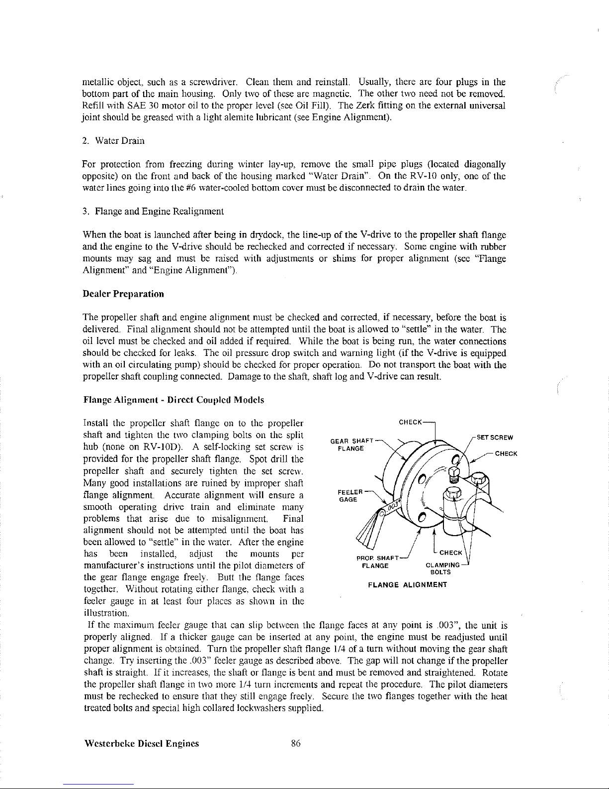
metallic object, such
as
a screwdriver. Clean them and reinstall. Usually, there are four plugs in the
bottom part of the main housing.
Only
two
of these are magnetic. The other
two
need not be removed.
Refill with
SAE
30
motor
oil
to the proper level
(see
Oil Fill). The Zerk fitting on the external universal
joint should
be
greased with a light alemite lubricant (see Engine Alignment).
2.
Water Drain
For protection from freezing during winter lay-up, remove the small pipe plugs (located diagonally
opposite) on the front and back of the housing marked
"Water Drain". On the RV-lO only, one of the
water
lines going
into
the
#6
water-cooled
bottom
cover
must
be disconnected
to
drain
the
water.
3.
Flange and Engine Realignment
When the boat
is
launched after being in drydock, the line-up of the V-drive
to
the propeller shaft flange
and the engine to the V-drive should
be
rechecked and corrected if necessary. Some engine with rubber
mounts
may
sag and must
be
raised with adjustments or shims
for
proper alignment (see "Flange
Alignment" and "Engine Alignment").
Dealer Preparation
The propeller shaft and engine alignment must
be
checked and corrected, if necessary, before the boat
is
delivered. Final alignment should not
be
attempted until the boat
is
allowed to "settle" in the water. The
oil
level
must
be
checked and
oil
added if required. While the boat
is
being run, the water connections
should
be
checked for leaks. The
oil
pressure drop switch and warning light (if the V-drive is equipped
with an oil circulating pump) should
be
checked for proper operation. Do not transport the boat with the
propeller shaft coupling connected. Damage to the shaft, shaft log and V -drive can result.
Flange Alignment - Direct Coupled Models
Install the propeller shaft flange
on
to
the propeller
shaft and tighten the
two
clamping bolts on the split
hub (none on
RV-IOD). A self-locking
set
screw
is
provided for the propeller shaft flange. Spot drill the
propeller shaft and securely tighten the set screw.
Many good installations are ruined
by
improper shaft
flange alignment. Accurate alignment will ensure a
smooth operating drive
train
and
eliminate many
problems that arise due to misalignment. Final
alignment should not
be
attempted until the boat has
been allowed
to
"settle" in the water. After the engine
has been installed, adjust
the
mounts per
manufacturer's
instructions
until
the
pilot
diameters
of
the gear flange engage freely. Butt the flange
faces
together. Without rotating either flange, check with a
feeler gauge
in
at
least
four
places
as
ShmY11
in
the
illustration.
GEAR
SHAFT
FLANGE
FEELER
GAGE
FLANGE
ALIGNMENT
SETSCREW
If
the maximum feeler gauge that can slip between the flange faces at any point is .003", the unit is
properly aligned.
If
a thicker gauge can
be
inserted at any point, the engine must be readjusted until
proper alignment
is
obtained. Turn the propeller shaft flange 1/4 of a turn without moving the gear shaft
change. Try inserting the
.003" feeler gauge
as
described above. The gap will not change
if
the propeller
shaft
is
straight.
If
it
increases, the shaft or flange
is
bent and mllst
be
removed and straightened. Rotate
the propeller shaft flange
in
two
more
1/4
turn increments and repeat the procedure. The pilot diameters
must
be
rechecked
to
ensure that
they
still engage freely. Secure the
two
flanges together with the heat
treated bolts and special high collared lockwashers supplied.
Wcstcrbcke Diesel Engines
86
Page 93
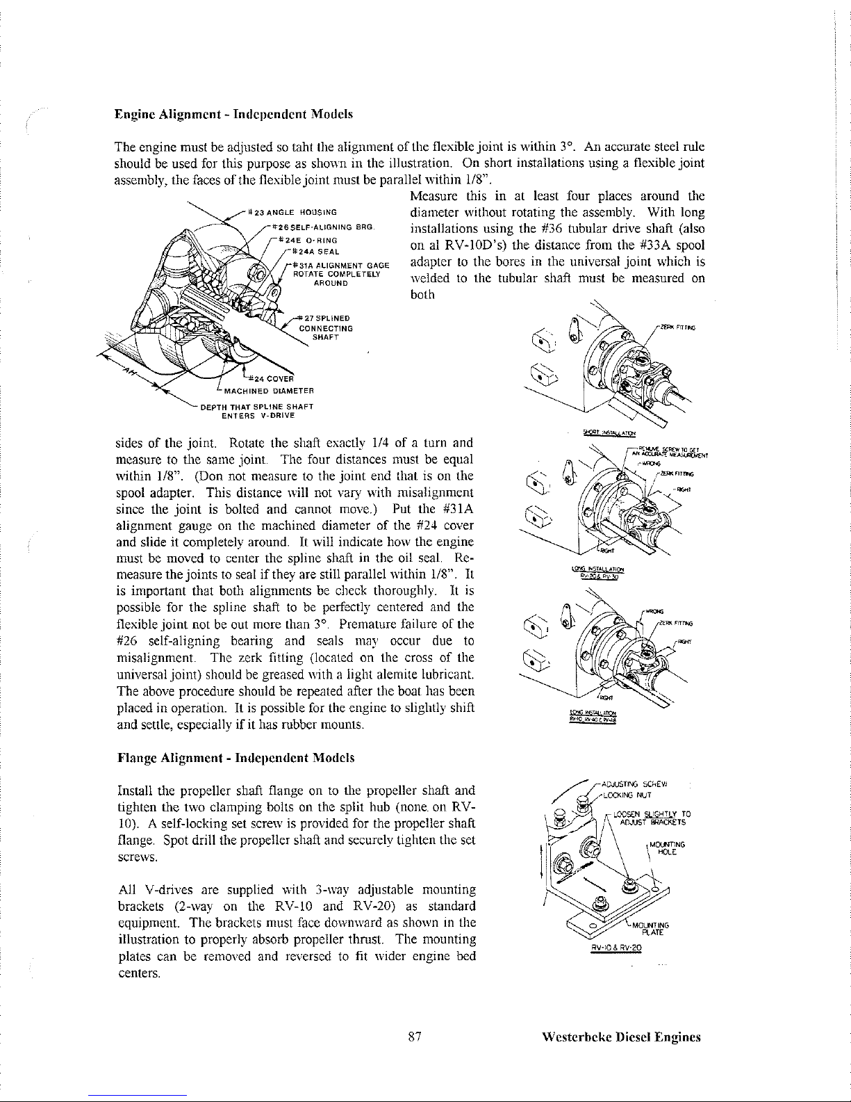
Engine Alignment -
Independent
Models
The engine must be adjusted
so
taht the alignment
of
the flexible joint is within 3°. An accurate steel rule
should be used for this purpose as shown in the illustration.
On short installations using a flexible joint
assembly, the faces
of
the flexible joint must be parallel within
118".
II;
23
ANGLE
HOUSING
GAGE
Measure this in at least four places around the
diameter without rotating the assembly. With long
installations using the #36 tubular drive shaft (also
on al
RV-IOD's) the distance from the #33A spool
adapter
to
the bores in the universal joint which is
welded
to
the tubular shaft must be measured on
both
DEPTH THAT SPLINE
SHAFT
ENTERS
V-DRIVE
sides
of
the joint. Rotate the shaft exactly
1/4
of
a turn and
measure to the same joint. The four distances must be equal
within
118".
(Don not measure
to
the joint end that is on the
spool adapter. This distance will not vary with misalignment
since the joint is bolted and cannot move.)
Put the #31A
alignment gauge on the machined diameter
of
the #24 cover
and slide it completely around.
It
will indicate how the engine
must be moved to center the spline shaft in the oil seal.
Re-
measure the joints
to
seal
if
they are still parallel within 1/8".
It
is important that both alignments be check thoroughly.
It
is
possible for the spline shaft
to
be perfectly centered and the
flexible joint not
be
out more than
3°,
Premature failure
of
the
#26 self-aligning bearing and seals may occur due
to
misalignment. The zerk fitting (Iocaled on the cross
of
the
universal joint) should
be
greased with a light alemite lubricant.
The above procedure should be repeated after the boat has been
placed in operation.
It
is
possible for the engine
to
slightly shift
and settle, especially
if
it has rubber mounts.
Flange Alignment
-
Independent
Models
Install the propeller shaft flange on
to
the propeller shaft and
tighten the two clamping bolts on the split hub (none. on
RV-
10). A self-locking set screw is provided for the propeller shaft
flange.
Spot drill the propeller shaft and securely tighten the set
scrc\vs.
All V-drives are supplied with 3-way adjustable mounting
brackets (2-way on the RV
-10 and RV -20)
as
standard
equipment. The brackets must face downward as shown in the
illustration to properly absorb propeller thrust. The mounting
plates can be removed and reversed
to
fit wider engine bed
centers.
87
ADJUSTIN:)
SCHEW
""LOCKIf'fj
NUT
RV-IO & RV-20
\
MOLfmNG
HOLE
Westerbeke
Diesel Engines
Page 94

Before installing the V -drive, loosen all the nuts
on
the mounting brackets and check to
see
that the studs
are in the center of the slots. Retighten the nuts.
Place the V -drive on the engine bcd, lining
it
up
"by
eye"
to the propeller shaft flange
as
closely
as
possible. Firmly bolt it down through the holes provided in
the mounting plates. Loosen the locking nuts
on
the adjusting screws. Slightly loosen the nuts on the
mounting brackets just enough
to
be able
to
move
the V-drive.
Many good installations are ruined
by
improper propeller shaft flange alignment. Accurate alignment
will ensure a smooth operating
drive
train
and
eliminated
many
problems
that
arise
due
to
misalignment.
Final alignment should not be attemptcd until the boat has been allowed
to
"settle" in the water. Adjust
the V-drive until the pilot diameters of the gear shaft flange and the propeller shaft flange engage freely.
Butt the flange faces together. Without rotating either flange, check with a feeler gauge in at least four
places as shown in the illustration.
If
the maximum feeler gauge that can slip between the flange faces at
any point
is
.oor, the unit
is
properly aligned. If a thicker gauge can
be
inserted at any point, the V-drive
must be readjusted until proper alignment
is
obtained. Turn the propeller shaft flange
114
of a turn
without moving the gear shaft flange. Try inserting the
.003" feeler gauge
as
described above. The gap
will not change if the propeller shaft
is
straight.
If
it increases, the shaft or flange
is
bent and must
be
removed
and
straightened.
Rotate
the
propeller
shaft
flange in
two
more
114
turn
increments
and
repeat
the procedure. The pilot diameters must
be
rechecked
to
ensure that they still engage freely. Tighten the
nuts
on
the mounting
brackets
and
the
locking
nuts
on
the
adjusting
screws.
Remove
the
set
screws
from
the brackets (none on
RV-IO
or RV-20),
spot
drill and securely tighten. Recheck the flange alignment
to
make sure the V-drive did not move out of alignment. Secure the
two
flanges together with the heat
treated bolts and special high collared lockwashers supplied.
GEAR
Sr-!A.F
T
FLANGE
FEELER
GAGE
(HECK-
CLAMPING
BOLTS
FLANGE
ALiGNMEN
T
Water
and Switch Connections
SET
SCREW
MOUNTING
PLATE
RV·30. RV'40 & RV-48
Hook up the water lines
to
the
two
pipe connections on the V-drive (intake and exhaust lines are
interchangeable). Generally, one line from the seacock to the V-drive and another from the V-drive to the
intake
of
the
engine
water
circulating
pump
are
utilized.
In
some
cases,
scuppers
through
the
hull
are
connected to and from the V-drive
to
provide independent water-cooling and are actuated
by
the
movement of the water. With closed cooling systems, the V-drive should
be
incorporated into the system
between the cooler and the suction side of the water pump.
Proper operating temperatures are from 140°
to 180°F, although safe operating temperatures
may
be
as
high
as
210°F. On the models equipped with an
oil circulating pump. the #49
oil
pressure drop switch and the
12
volt #49A warning light should be
hooked
up
per the wiring diagram. The switch
may
be
grounded
to
any part of the V -drive or engine
(either terminal may be used
for
the ground).
Westerbeke Diesel Engines
88
Page 95

Oil
Fill
Pull out the
#21
oil level gauge. Unscrew the #12 breather cap and fill the V-drive with SAE #30 motor
oil through the #12A breather elbow. On the RV-IO only, the oil
may
be added
by
removing the plug in
the #6D top cover. See table below for approximate oil capacities. The amount varies with the angle
of
installation. The oil level should be checked with the oil level gauge fully inserted in the unit. The proper
level is between the "H" and "L" marks on the gauge. Add a 2 ounce tube
of
Molykote (molybdenum
disulfide), which is supplied with each V-drive for extra lubrication and break-in.
It
provides protection
against scoring or galling
of
gears, bearings and other moving parts. Additional Molykot after break-in is
not required. Reinstall the breather cap. The oil level should
be
rechecked after the unit has been run and
allowed
to
sit for about a minute. Add oil
if
necessary.
Oil Capacity (approx.)
RV-IO RV-20 RV-30 RV-40
I
pint 2 pints 3 pints 4 pints
# 12 BREATHER CAP
(UNSCREW FOR
OIL FILL)
WATER LINE
OIL
FILL
'""12A
BREATHER
ELBOW
WATER
DRAIN
OIL LEVEL
GAGE
(PULL
UP
TO
REMOVE)
WATER LINE
RV-48
4 pints
89
Westerbcke Diesel Engines
Page 96
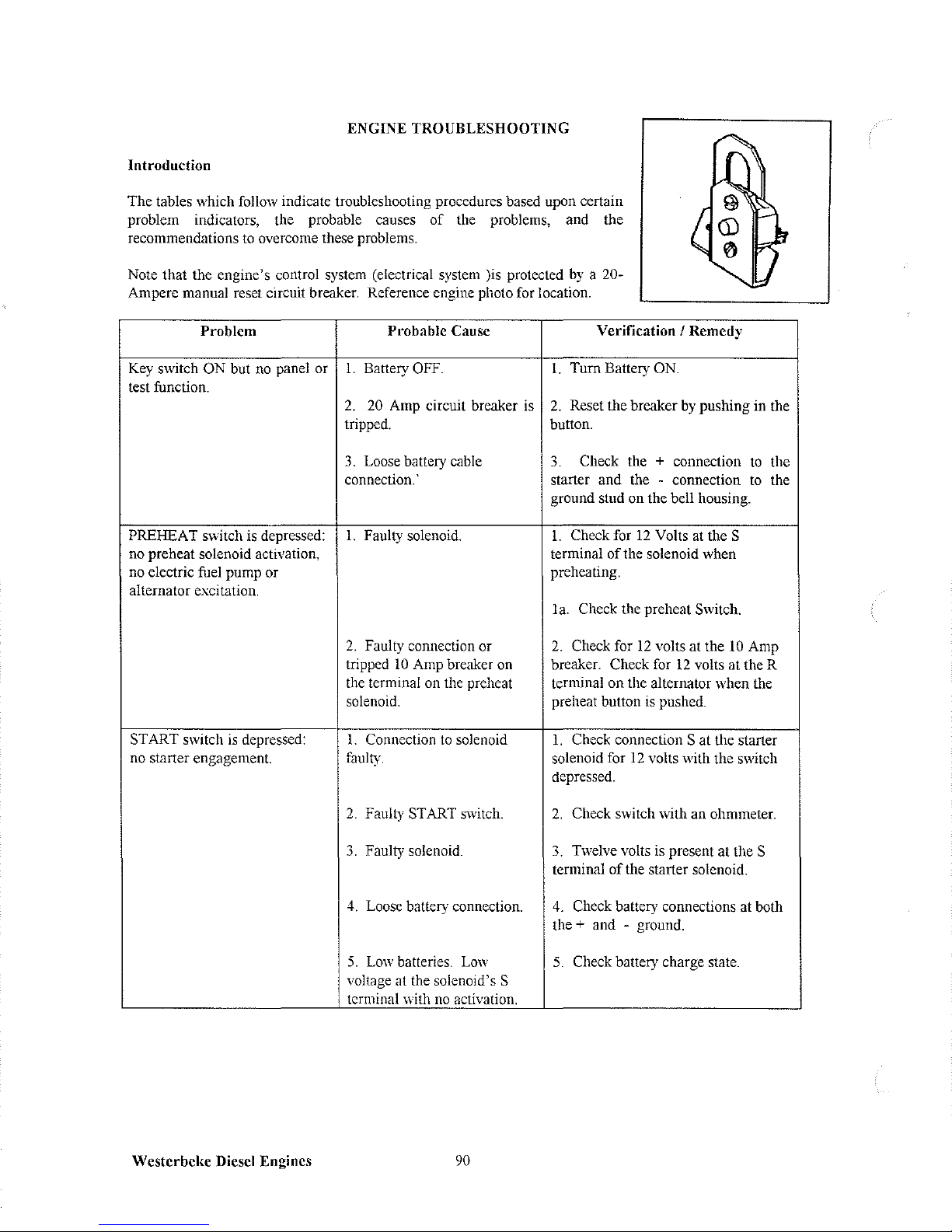
ENGINE TROUBLESHOOTING
Introduction
The tables which follow indicate troubleshooting procedures based upon certain
problem indicators, the probable causes of the problems, and the
recommendations
to
overcome these
problems.
Note that the engine's control system (electrical system lis protected
by
a 20-
Ampere
manual
reset
circuit
breaker.
Reference engine
photo
for
location.
Problem
Probable Cause
Key switch
ON but
no
panel or I. Battery OFF.
test function.
2.
20
Amp circuit breaker is
tripped.
3.
Loose battery cable
connection. '
PREHEAT switch is depressed:
1.
Faulty solenoid.
no
preheat
solenoid activation,
no electric fuel pump or
alternator
excitation.
START switch
is
depressed:
no
starter
engagement.
Westcrbcke Diesel Engines
2.
Faulty connection or
tripped
10
Amp breaker on
the terminal on the preheat
solenoid.
1.
Connection
to
solenoid
faulty.
2.
Faulty START switch.
3.
Faulty solenoid.
4.
Loose
battery
connection.
5.
Low
batteries.
Low
voltage at the solenoid's S
terminal
with
no
activation.
90
Verification / Remedy
1.
Turn Battery ON.
2.
Reset the breaker
by
pushing in the
button.
3.
Check the + connection
to
the
starter and the - connection
to
the
ground stud on the bell housing.
1.
Check for
12
Volts at the S
terminal
of
the solenoid when
preheating.
la. Check the preheat Switch.
2.
Check for
12
volts at the
10
Amp
breaker. Check for
12
volts at the R
terminal on the alternator when the
preheat button is pushed.
1.
Check connection S at the starter
solenoid for
12
volts with the switch
depressed.
2.
Check switch with an ohmmeter.
3.
Twelve volts is present at the S
terminal
of
the starter solenoid.
4.
Check battery connections at both
the
+ and - ground.
5.
Check battery charge state.
Page 97

Problem
Engine cranks, but does not
start.
Failure to stop.
Engine stops.
Battery runs down.
Probable
Cause
l.
Shut-offvalvc at fuel tank.
Verification
I
Remedy
l.
Return shut-off valve to its
ON
position. Now bleed the fuel system.
2.
Faulty fueling system.
2.
Check for fuel to engine.
3.
Air is in the fuel system.
3.
Bleed the fuel system. Locate the
leak and correct it.
4 Fuel pump is not operating. 4. Check pump operation.
5.
Fuel filters are clogged.
5.
Clean/replace filters.
6.
Blockage
in
exhaust.
6.
Remove exhaust hose from the
engine and crank to start.
7.
Injection pump fuel solenoid
7.
Check solenoid for activation.
faulty.
1.
Key switch
2.
Alternator.
1.
Fuel starvation. Fuel shut-
off
is
turned OFF.
l.
Check switch will not open run
circuit.
2.
Check EXC terminal from
alternator with harness unplugged.
1.
Check to see that the shut-off valve
at
the fuel tank is
ON.
2.
Fuel pump is inoperative.
2.
Inspect the fuel pump to see
ifit
is
pumping. Manually prime the system
and check the return flow.
3.
Water
is
in the fuel.
3.
Pump water out
of
the bottom
ofthe
fuel tank(s) and change the fuel filters
and bleed the fuel system.
4.
Exhaust system is restricted.
4.
Check exhaust system for some type
of
blockage such as carbon buildup at
the exhaust elbow. Check for a fault
in
the muffler. Check for a collapsed
exhaust hose.
1.
Alternator output is low.
2.
Faulty alternator.
3.
Bad battery connections.
91
1.
Check drive belt tension. Make an
OUlput
cheek with a voltmeter at the B+
terminal on the alternator.
2.
Voltage leak through the alternator
when not operating.
3.
Connections are corroded or loose at
the batterv orland at the engine.
Westerbeke
Diesel Engines
Page 98

MAINTENANCE
AND
ADJUSTMENTS
Introduction
This section contains a scheduled preventive
maintenance
program
and
several
adjustment
procedures
the
owner/operator can perform without the benefit
of
sophisticated and expensive tools and instruments.
Preventive Maintenance
Perform the preventive maintenance in accordance with the schedules listed in the following paragraphs.
Adherence
to
these schedules will ensure the equipment is maintained in the best possible condition and
that it will perform
to
expectations. Those items marked
by
an asterisk (*) are recommended
to
be
performed
by
an authorized dealer or distributor.
Daily (before each use)
1.
Check the oil sump level. Maintain the oil level at or near the upper level mark on dipstick.
2.
Check the coolant level in the plastic recovery tank. Maintain this level at or above the level marked
ADD.
3.
Check transmission's lubricant level, and add additional lubricant as needed.
4.
Visually inspect the unit; check for loose belts, chafed or broken wires, loose brackets and fittings,
damaged hoses, loose clamps, and other equipment not properly secured.
5.
Check the fuel supply. Fill tank(s) with a good grade
of
No.2 diesel fuel,
if
required.
6.
Check the primary filter/water separator. Drain and service as required. (A primary filter/water
separator is optional, but strongly recommended.)
7.
Check the engine's gauges or lights for proper oil pressure, operating temperature, and starting
battery charging voltage once the engine is operating.
8.
Check the alternator's output gauge (if installed) for proper DC voltage.
Monthly
Check the condition
of
the zinc anode in the heat exchanger's sea water circuit. Clean or replace the
anode,
as
required.
Keep
the
area
inside
the
heat
exchanger clean of zinc
anode
debris.
Sen'icing After Initial 50 Hours
of
Operation
1.
Change the engine's lubrication oil and oil filter.
2.
Replace the secondary fuel filter and the filter element in the base
of
the fuel pump. Service the
primary system filter
is
installed.
*3.
Torque the cylinder head hold-down bolts.
*4.
Adjust
valve
clearances.
5.
Adjust the alternator and water pump drive belt tension,
if
required.
Westerbeke Diesel Engines
92
Page 99
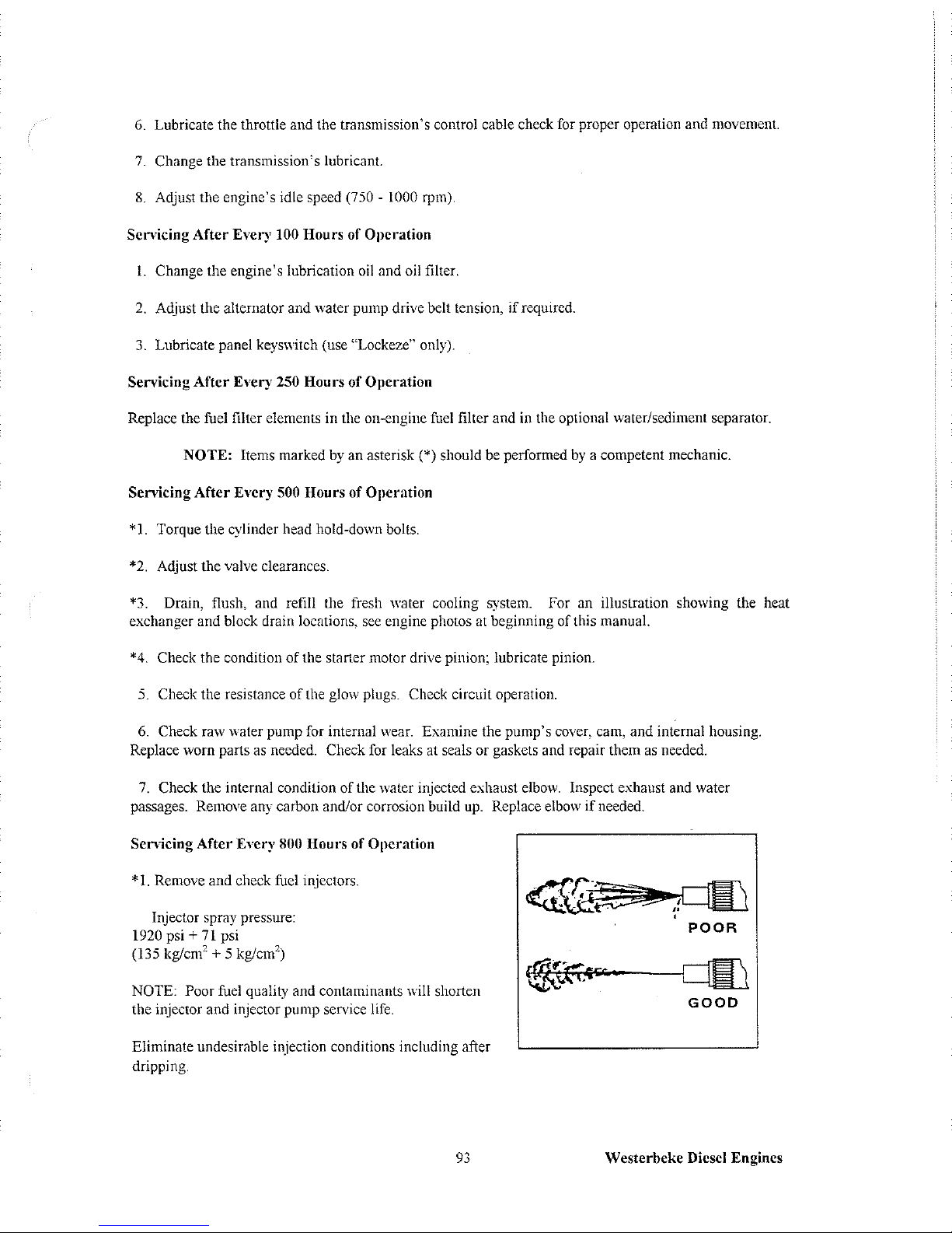
6.
Lubricate the throttle and the transmission's control cable check for proper operation and movement.
7.
Change
the
transmission's
lubricant.
8.
Adjust the engine's idle speed (750 - 1000 rpm).
Servicing
After
Every 100 Hours of Operation
1.
Change the engine's lubrication
oil
and oil filter.
2.
Adjust the alternator and water pump drive belt tension,
if
required.
3.
Lubricate panel keyswitch (use "Lockeze" only).
Servicing
After
Every 250 Hours
of
Operation
Replace the fuel filter elements in the on-engine fuel filter and in the optional water/sediment separator.
NOTE: Items marked
by
an asterisk (*) should be performed
by
a competent mechanic.
Servicing
After
Every 500 Hou rs
of
Operation
*1.
Torque the cylinder head hold-down bolts.
*2.
Adjust the valve clearances.
*3.
Drain, flush, and refill the fresh water cooling system. For an illustration showing the heat
exchanger
and
block
drain
locations,
see
engine photos
at
beginning of this
manual.
*4.
Check
the
condition
of
the
starter
motor
drive
pinion; lubricate pinion.
5.
Check the resistance
of
the glow plugs. Check circuit operation.
6.
Check raw water pump for internal wear. Examine the pump's cover, cam, and internal housing.
Replace worn parts as needed. Check for leaks at seals or gaskets and repair them
as
needed.
7.
Check the internal condition of the water injected exhaust elbow. Inspect exhaust and water
passages. Remove any carbon andlor corrosion build
up.
Replace elbow
if
needed.
Sen-icing
After
Every 800 Hours of Operation
*
1.
Remove and cheek fuel injectors.
Injector
spray
pressure:
1920 psi +
71
psi
(135 kg/cm'
+ 5 kg/cm')
NOTE: Poor fuel quality and contaminants will shorten
the injector and injector pump service life.
Eliminate undesirable injection conditions including after
dripping.
93
f. ~ -,
.
~
..
,,,..~.-
-~
.'
,I
,
POOR
GOOD
Westerbeke Diesel Engines
Page 100

*2. Check the compression pressure. Remove each glow plug and check each cylinder's compression
pressure. The engine's speed is at 280 rpm.
*3.
Check the battery-charging alternator for proper operation.
*4. Check the tightness
of
bolts, nuts, and clamps.
Westerbcl{c Diesel Engines
94
 Loading...