

Page 1

~
o
,"lo!
!».!'<. .
·OPERAT.ORS
,<)
MANUAL··
·5.5KWEDC60HZ
:
;
5.0KW
Single
(MARINE
••
___
0
___
••
DIE·
EDC
..
Phase·
GENERATORS
.....
50HZ
_____
• •
__
......
__
••
WESTERBEKE
MYLES
WEBSITE:
§..Gfi!4
...,,.,,.
REVISION
DECEMBER
CORPORATION'
STANDISH
INDUSTRIAL
WWW.WESTERBEKE.COM
Member
National
MarineManufllcturers
.'
3
2011
150
PARK.
.
JOHN
HANCOCK
TAUNTON
---.-
'--~--"------"
ROAD
MA
02780
Association
.
Page 2

·
CALIFORNIA
PROPOSITION
65
WARNING
Marine
exhaust
are
known
to
cause
and
Exhaust
colorless
unconsciousness
exposure
-
-Nausea
-Headache
-
gasses
gas.
can
Dizziness
Weakness
and
contain
Carbon
and
include:
Sleepiness
diesel
and
some
to
the
cancer,
other
reproductive
A
Carbon
Monoxide
death.
and
gasoline
of
its
constituents
State
of
California
birth
defects,
harm.
WARNING
Monoxide,
is
poisonous
Symptoms
-
Throbbing
-
Muscular
-
Vomiting
-Inability
engine
an
odorless
and
of
Carbon
in
Temples
Twitching
to
Think
and
can
cause
Monoxide
Coherently
IF
YOU
OR
GET
OUT
seek
medical
until
it
has
·:WARNING
GenelalolB
Produce
CARBON
Regular
Maintenance
~~::'~;.,!
MONOXIDE
Required
A
WARNING
should
be
generator.
WESTERBEKE
MONOXIDE
are
inexpensive
hardware
DECAL
fixed
DETECTORS
store.
ANYONE
INTO
been
to a bulkhead
also
and
ELSE
THE
FRESH
attention.
inspected
is
provided
recommends
near
easily
EXPERIENCE
AIR
IMMEDIATELY.
Shut
down
and
repaired.
by
WESTERBEKE
near
your
installing
the
engine
room.
obtainable
at
ANY
OF
the
unit
and
engine
or
CARBON
They
your
local
THESE
If
symptoms
and
dl!
not
SYMPTOMS,
pelSist,
restart
Engines & Generators
Page 3

SAFETY
INSTRUCTIONS
INTRODUCTION
Read
this
safety
manual
caused
by
failure
to
follow
precautions.
take
the
personne~
The
following
the
American
PREVENT
A
while
power.
•
Do
enclosures
•
Shut
equipment.
•
Use
equipment.
•
Make
(particularly
•
Remove
electrical
•
Do
circuits,
transfer
result if
• Electrical shock
capacitor.
together.
PREVENT
A
exhaust
very
•
Always
recovery
A
• In case of
before
Know
when
necessary
and
precautions
your
machinery.
safety
instructions
Boat and
ELECTRIC
WARNING:
engine
Lethal
not
operate
off
insulated
sure
not
connect
00
is
running,
voltage
thls
and
covers
electrical
mats
your
clothing
shoes)
wristwatch
equipment.
utilily
except
through a ship-to-shore
switch.
Damage
thls
procedure
results
Discharge
BURNS -HOT
WARNING:
system
hot!
WARNING:
touching
00
components. A running
check
the
tank.
Steam
an
engine
the
power
carefully.
fundamental
dangerous
Yacht
Council
SHOCK
not
touch
or
when
is
present
machinery
in
place.
before
whenever
and
when
handling
and
all jewelry when
shore
to
vessels
is
not
from
capacitor
ENGINE
not
touch
engine
coolant
can
overheat,
engine
Most
accidents
rules
and
conditions
to
protect
yourself,
are
in
complwnce
(ABYC)
AC
electrical
connected
at
these
without
accessing
working
skin
are
power
followed.
handling a charged
by
shorting tenuinals
hot
engine
connections
to
connections!
electrical
electrical
on
electrical
dry,
not
electrical
working
to
vessels
double
AC
generator
.
parts
engine
level
at
the
cause
injury
or
death!
allow
the engine
or
checking
the
are
exist
and
your
with
standards.
shore
damp
equipment.
on
AC
throw
may
or
gets
coolant
to
cool
coolant.
PREVENT
A
•
Prevent
sparks
pump,
vapors.
removing
•
Do
arrester.
•
Do
Backfire
•
Do
the
engine/generator
chances
•
Be
PREVENT
A
injury
•
Follow
hatches
after
running
before
•
All
equipment
•
•
•
•
•
•
BURNS -FIRE
WARNING:
flash
to
occur
or
other
Use a suitable
not
operate
Backfire
not
operate
can
not
smoke
fuel
system.
of
aware
BURNS -EXPLOSION
WARNING:
or
death!
re-fueling
closed
fueling.
the
starling
fuel
vapors
when
handling
well-ventilated
Do
not
fill
Shut
off
the
the
fuel
system.
spill.
DO
sources
of
servicing.
the
fuel
system.
Do
not
alter
Be
sure
all fuel
Be
certain
free of
leaks.
Make
sure a fire
properly
Extinguishers
for
all
applications
Fire
can
fires.
Do
near
the
potential
the
fuel
line,
without a Coast
can
cause
with
the
cause
severe
or
pennit
Keep
clean
fire.
Wipe
up
- diesel fuel
Explosions
safely
when
fueling.
Check
below
blower.
and
the
NOT
fire
Ensure proper
fuel
maintained.
your
are
and
area
out
fuel
fuel
service
Take
allow
near
or
modify
supplies
line
extinguisher
rated
Run
engine.
highly
storing
away
of the
tank(s)
the
fittings
ABC
encountered
cause
injury
not
smoke
carburetor,
sources
container
carburetor,
air
flames
the
and
will
valve
care
any
fuel
the
Be
of
to
Guard
severe
cleaner/silencer
injnry
or
compartment
free
of
all
spilled
bum.
from
fuel
instructions.
Open
for
fumes/vapor
the
blower
explosive.
fuels.
from
spark-producing
reach
of
while
at
in
catching
smoking,
system
ventilation
fuel
system.
have a positive
are
adequately
is
familiar
by
the
or
or
pennit
fuel
spilled
catch
or
fuel
Approved
injnry
or
death.
sparks
debris
fuel
vapors
Keep
and
for
Use
Store
fuel
children.
the
engine
the
engine
any
open
or
engine
exists
installed
with
its
NFPA
in
thls
death!
flames
or
line,
filter,
fuel
fuel or
fuel
all
fuel
when
filters.
flame
or
death.
removed.
to occur
and
to
and
ventilate cabin
four
extreme
flames,
shutoff
nearby
proper
are
environment.
near
the
minimize
engine
can
cause
the
vessels
before
minutes
care
in
a
is
running.
when
servicing
fuel
that
or
when
when
servicing
valve.
tightened
and
use.
appropriate
oil.
might
other
the
and
is
~
WESTERBEKE
Engines & Generators
i
Page 4

SAFETY
INSTRUCTIONS
ACCIDENTAL
A
WARNING:
or
death!
•
Disconnect
generator.
it
last.
•
Make
starting.
•
Make
re-installed
BAnERY
A
WARNING:
or
death!
•
Do
not
being
highly
arcing
equipment
duriog
•
Never
positive
Do
not
together.
Ventilate
accumulation
disturb
is
being
•
Avoid
burns
wristwatch,
the
battery.
•
Always
the
battery
and
BATTERY
A
WARNING:
severe
STARTING
Accidental
the
Remove
certain
all
certain
all
before
EXPLOSION
Battery
smoke
or
serviced.
explosive
or
by
lit
in
the
servicing.
connect
contacting
or
reconnect
the
(+) connection
test the battery
Sparks
any
comparttnent
of explosive
the
battery
charged.
sparks
rings,
tum
the
connections.
it last
ACID
injnry
or
death!
battery
cables
the
negative
personnel
Covers,
starting
explosion
allow
an
Lead
acid
gas,
which
tobacco
products.
vicinity
negative
condition
could
ignite
charger
the
terminals
that could
and
any
battery
when
Sulfuric
startIng
before servicing
lead
are
clear
gnards,
and
the
engine.
open
flame
batteries
can
be
Shut off
to
prevent
(-) battery
termioal
charger
Remove
acid
of the starter
by
battery
containing
gases.
To
connections
with
cause
an
other
jewelry before
off before
the
disconnecting
in
batteries
can
cause
first
and
of
the
hatches
can
cause
near
emit
hydrogen,
ignited
electrical
cable
shorting the
gases
batteries
avoid
while
tools,
explosion.
negative
the
injury
the
engine/
reconnect
engine
before
are
injury
the
battery
a
by
electrical
all
electrical
arcing
to
the
solenoid.
termioals
or
fuel
vapors.
to
prevent
sparks,
do
the
battery
etc.,
to
prevent
Remove
handling
disconnecting
lead
first
battery.
can
cause
not
TOXIC
•
EXHAUST
A
WARNING:
Ensure
discharged
regularly
manifolds/water-injected
•
Be
sure
Run
blowers
•
Do
not
equipped
detector that
boat
builder or
detectors.
•
For
additional
(educational
A
WARNING:
odorless
nausea
•
•
• Although
AVOID
gas.
or
Do
not
frnnes
can
systems.
copper
Do
not install
through
exhaust
enter
the
flow
of exhaust.
exhaust
gas
is present in
symptoms
poisoning
Vomiting
Dizziness
Headache
Nausea
MOVING
Carbon
that
the
exhaust
from
for
leaks
the
unit
when
run
the
generator
with a functioning
complies
dealer
information
information
Carbon
Inhalation
death!
use
copper
rapidly
Exhaust sulfur
tnbing
resulting
exhaust
portholes,
discharge
exhaust
diesel
fumes
from
or
signs
are:
Inability
Throbbing
Muscular
Weakness
GASES
monoxide
system
the
engine.
and
make
elbow
and
its
surroundings
running
set
with
for installation of approved
on
monoxide
produces
tnbing
destroy
causes
in
outlet
vents,
outlet
is
discharge
Avoid
overloeding
engine
exhaust
gasoline
diesel
exhaust
of carbon
to
(CO]
is
adequate
Check
the
sure
the
is
securely
the
generator
or
engine
marine
carbon
ABYCA-24.
refer
to
ABYC
Carbon
(CO]
flu·like
in
diesel
exhaust
copper
tnbing
rapid
exhaust/water
where
exhaust
or air
conditioners.
near
the
waterline,
outlet
and
the
gases
engines,
fumes.
monoxide
think
coherently
in
temples
twitching
and
sleepiness
PARTS
is a deadly
exhaust system
exhaust
are
well ventilated.
set or engine.
unless
Consult your
Monoxide).
is
an
to
expel
attached.
the boat
monoxide
T-22
invisible
gas!
symptoms,
systems.
in
exhaust
deterioration of
lealcage.
can
be
If
the
water
close
or
restrict
craft.
are
not
as
toxic
carbon
monoxide
Some
of
the
inhalation or
gases
is
Diesel
drawn
engine
could
the
as
•
When
servicing
level,
wear
protection.
destructive.
at
once
off
into
the
eyes
caps.
the
battery
rubber
gloves, a rubber
Batteries
If
it
comes
with
water.
inadvertently
contain
in
contact
Acid
or
checking
sulfuric
may
when
apron,
acid
with
splash
removing
the
and
which
your
on
electrolyte
electrolyte
eye
is
skin,
wash
the
skin
or
-.y:
A
WARNING:
or
death!
it
•
Do
not service
sitnation
make
touching
components.
operating
WESTERBEKE
Engines & Generators
ii
arises
moving
Rotating
the
in
adjustruents,
engine
which
parts
parts
it
and hot
can
while
is
absolutely
use
exhaust
cause
it
is
running.
extreme
injury
If
necessary
care
to
system
a
to
avoid
Page 5

-----
----------
-
•
Do
not
wear
loose
equipment;
jackets,
could
•
Make
Keep
places
•
Do
not
the
engine
•
Stay
when
be
caught
HAZARDDUS
A
WARNING:
tie back
shirts,
be
caught in
sure
all
protective
at
all
times.
check
is
clear
of
the
engine
in these
NOISE
sleeves,
attaching
fluid
operating.
the
loss!
•
Never
•
Do
not
removed.
•
Do
not
open.
A
WARNING:
mentally
operate
an
run
an
engine
run
engines
or
physically
clothing
long
hair
rings,
moving
hardware
shields
and
levels
dtive
shaft
is
running;
rotating
High
noise
engine
without its
with
for
long
Do
not
work
incapacitated
or
jewelry
and
necklaces
parts.
guards
or
the
and
heir
parts.
levels
the
periods
on
SAFETY
when
avoid
wearing
or
is
properly
in
their
dtive belts
the
transmission
and
clothing
can
cause
muffler
air intake
machinery
with
by
fatigue!
(silencer)
servicing
bracelets
tightened.
respective
tension
can
hearing
installed.
their
enclosures
when
INSTRUCTIONS
loose
that
while
coupling
easily
you
are
ABVC,
INSTALLING
Read
for
recommendations
ABYC
"Safety
Order
NFPA
''Fire
Order
USCG
"USCG
Order
NFPA
the
following
safety
codes
(American
Standards
from:
ABYC
3069
Solomon's Island
Edgewater,
(National
Protection
from:
NFPA
11
Tracy
Avon
Industrial Park
Avon,
MA
(United
33CFR183"
from:
U.S.
Government
Washington,
AND
DIESEL
ABYC,
and
when
Boat
for
MD
21037
Fire
Standard
Drive
02322
States
D.C.
USCG
PUBLICATIONS
ENGINES
NFPA
standards.
installing
and
Yacht
Small
Craft"
Rd.
Protection
for
Motor
Coast
Guard)
Printing
20404
Office
and
USCG
Follow
their
your
engine.
Council)
Association)
Craft"
FOR
publications
OPERATORS
Many
of
in
your
notes
to
carefully,
procedures.
GASOLINE
Preparations
thorough
Council's
combination
Sections
H-2
P-l Exhaust
P-4
E-9
All
installations
Regulations
MANUAL
the
preceding
Operators
highlight
maintain
Manual
critical
ENGINE
to install
examination of
(ABYC)
of
sources
of
the
ABYC
Ventilation
Inboard Engines
DC
Electrical
must
(FCR).
safety
along
information.
your
equipment,
AND
an
engine
the
standards.
including
standards
Systems
Systems
comply
tips
and
wamings
with
other
cautions
Read
your
and
follow
GENERATOR
should begin
American
These
the
of particular interest
with
INSTALLATIONS
with
Boat
and
standards
USCG
the Federal
are
and
are
manual
all
s;,rety
Yacht
a
the
Code
repeated
and
a
NFPA.
are:
of
~
WESTERBEKE
Engines & Generators
iii
Page 6

When
installing
attention
WESTERBEKE
be paid
to
the
following
INSTALLATION
engines
information:
and
generators
it
is
important
t)1at
strict
CODES
Strict
when
AND
federal
regulations,
installing
REGULATIONS
engines
SIPHON-BREAK
For installations
or
will be
break in the
minimum
the
exhaust manifold
raw
water
If
you
have
to
the vessel's
Siphon-break.
NOTE:
A
siphon-break
operation.
engine
damage.
EXHAUST
The exhaust
prevent
of the
water
vessels
A detailed
diesel engines and generators
copies
where
the
below
the
vessel's
raw
water
supply
of
20"
above
injection
damage
any
doubt
waterline
to
the
about
requires
Failure
to
properly
Consult
SYSTEM
hose
must
be
from
entering
hull.
40
page Marine Installation Manual covering gasoline and
can
be obtain off our website in pdf
ABYC
guidelines,
and
generators
exhaust
the
vessel's
engine
under
waterline,
hose
the
the
periodic
in a
manifold/water
provisions
to
the
waterline.
port
is
at or
and
possible
position
of the
vessel's
inspection
maintain a siphon-break
the
siphon-break
certified
the
for
marine
exhaust
under
is
provided with each unit
and
safety
marine
environment.
injected
must
exhaust
elbow.
Failure
below
the
flooding
water-injected
various
operating
and
manufacturer
use.
The
any
sea conditions
form.
codes mnst
exhaust
be
made
This
to
use a siphon-break
load
of
the
cleaning
can
for
system
www.westerbeke.com
be
complied
elbow
to
install a
hose
must be looped a
waterline
will
boat.
exhaust
conditions,
result
proper
elbow
install a
to
ensure
in
catastrophic
maintenance.
must be designed
and
at
sold.
Additional
any
with
is
close
siphon-
when
result in
relative
proper
angle
to
to
AVAILABLE
YOUR
DEALER
FROM
WESTERBEKE
....v:
WESTERBEKE
Engines & Generators
iv
Page 7

~--------
..
-------
..
----,,------_
..
_-----------
-
--
-----------
TABLE
Parts
Identification
Introduction
Fuel,
Engine
Preparations
Digital
LCD
Sequence ...................................................
Digital
Generator
Daily
Routine
............................................... : ........
Oil
for
Control
Control
Break-In
Maintenance
Fuel
System
Cooling
Fresh Water Cooling CircuiL. ..................... 14
Changing the Coolant.. ....................
Air Intake ..................................................... 14
. Thermostat ...................................................
Raw Water Intake Strainer ..........................
Raw Water Cooling Circuit ......................... 16 Circuit Breaker
Heat Exchanger ...........................................
Raw Water Pump .........................................
Engine
Engine
Remote
Starter
Troubleshooting ........................................... 20
Generator
Wiring
Wiring
Wiring
.......................................................
System
Lubricating
Oil Change ......................................
Oil Filter (optional) ........................
Motor
Specifications
Diagram
Diagram
Diagram
............................................. 2 Engine
and
Engine
Initial
Panel..
Box
..............................................
Procedure
Coolant...
Start-Up
...............
.........................
........ ; ................................
............................
.......................................................
Schedule
(Chart)
.........................
..................................................
~
........... 14 Battery Care ................................................ .33
Oil
.......................................
....................................................
..................................
#52414
#52793
#53477
.....................................
.............
.................................
.....................
OF
CONTENTS
Adjustments
.3
Drive Belt Adjustment ................................. 23
5 Torquing the Cylinder Head Bolts .............. 23
6 Generator Frequency Adjustment.. .............. 24
7 Electronic Governor .................................... 24
7 A Valve Clearance Adjustment ....................... 25
8 Engine Compression .................................... 25
9 Spill Timing ................................................. 26
9 Testing Glow Plugs ...................
10
12 Fuel Injectors ............................................... 28
13
Testing Oil Pressure ..................................... 27
Engine
Troubleshooting
Alternator
Shore
Power
15
15
16
16
17
17
18
.
19
21
22
22A
22B
Generator
Generator Single Phase ...............................
Internal Wiring Diagram .............................
No Load Voltage Adjustment .......... , ........... 37
AC
Terminal Block Connections ............... .38
Dual Exciter Model .................................... .39
EDC Generator Troubleshooting ................ .40
Lay-up
Power
Metric
and
Take-Off
Conversion
Suggested
...........................................
'"
(Chart)
Testing
Information
............................................
Transfer
Switch
......................................
'"
........................................ .36
Recommissioning
........................
............................
.........................
.................................................
Data
Spares
............................................
(Chart)
........................
23
............... 27
29
.31
34
.35
36
36
.A(
A3
44
..46
.
.
"""
WESTERBEKE
Engines & Generators
1
Page 8
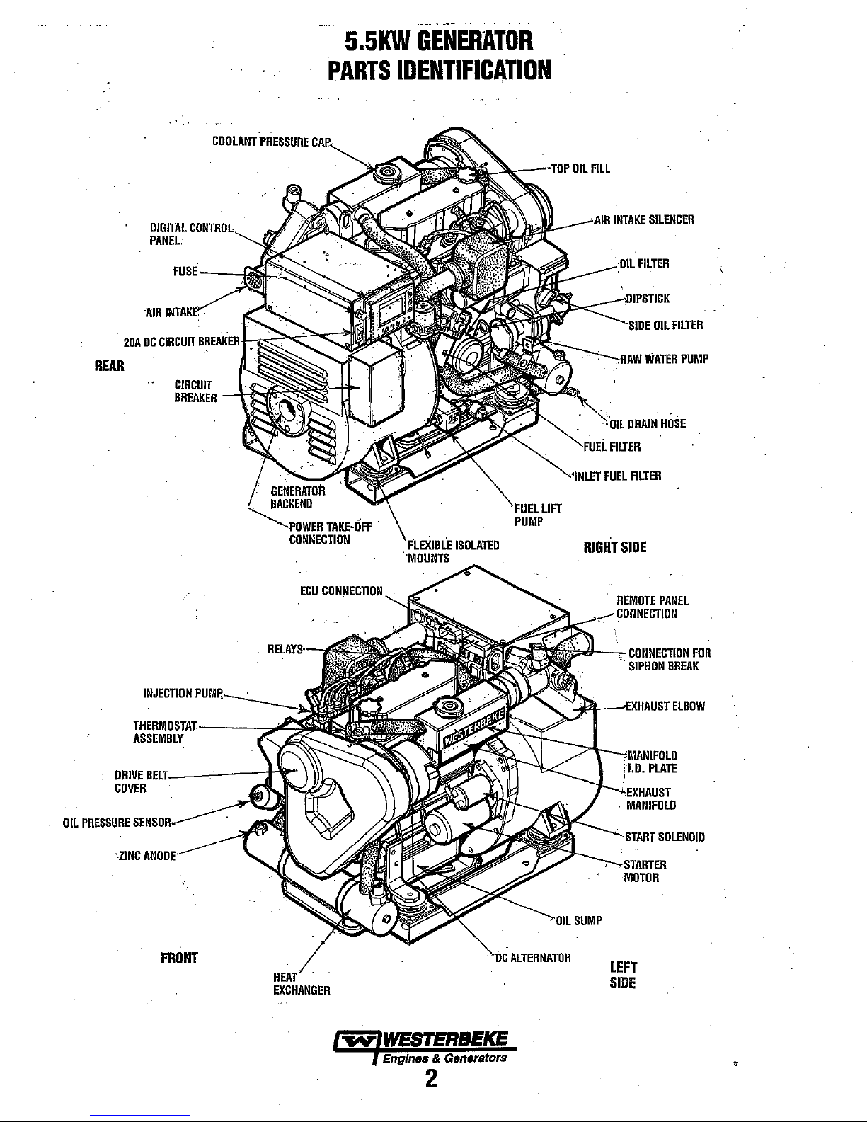
5~5KWGENERATOR
20A
REAR
DIGITAL
PANEL.
'AIR
DC
CIRCUIT
COOLANT
rn"'Dm
BREAKER
CIRCUIT
PARTS
PRESSURE
IDENTIFICATION
~..---IOP
t--~?>-...t"""'C'"
OIL
FILL
:---DO'"
FUEL
FILTER
DRAIN
FILTER
FILTER
OIL
FILTER
WATER
HOSE
PUMP
OIL
PRESSURE
........
INJECTION
DRIVE
BEL1·_-----:t-'t~·
COVER
SENSDR·"--
·.ZINC
..
PUWI~_-.:c
",nr.---
'·OWI;R
TAKE·OFF
CONNECTION
ECU,
C(
INNElmO~1
FLEXIBLE'ISOLATED'
"MOUNTS
,
LIFT
RIGHT
SIDE
REMOTE
,
CONNECTION
il;;./1-~
~~--I;XHI\UST
CONNECTION
SIPHON
1.0.
,
,
MANIFOLD
-----,
..
ODT
'STARTER
MOTOR
PLATE
SOLENOID
PANEL
FOR
BREAK
ELBOW
FRONT
EXCHANGER
~
WESTERBEICE
Engines & Generators
2
SUMP
ALTERNATOR
LEFT
SIDE
Page 9

This
WESTERBEKE
WESTERBEKE'S
technology.
dependable
Thank
In order
important
manual
manual
throughout.
your
This
be
available
planning
your
Installation
Customer
,...,."
We
take
performance
you
for
selecting
to
get
the full
that
you
is
designed
carefully
Should
nearest
WESTERBEKE
is
your
Operators
from
to
install
WESTERBEKE
Manual.
Identification
lWESTERBEKE
I E!ngines &
Cusiomer
WESTERBEKE
MAIN
HOMETOWN,
Model
Expires
Identification
STREET
Engine
long
years
great
pride
of
our
WESTERBEKE.
use
and
operate
and
your
this
OWNER
USA
and
to
help
you
observe
your
engine
Manual. A Service
WESTERBEKE
equipment
dealer
for
Ser.
is a product
of
experience
in
engines
benefit
maintain
do
all
the
require
dealer
contact
WESTERBEKE'S
of
the
superior
and
from
it
correctly.
this.
Please
safety
servicing,
for
assistance.
Manual
dealer.
yourself, contact
your
precautions
Card
Generators
#
INTRODUCTION
WESTERBEKE
and
advanced
durability
generators.
engine,
This
read
this
contact
will
If
you
also
are
span
and
software
WESTERBEKE
provided
WESTERBEKE
it
is
be
the
but
WESTERBEKE
to
determine
product
NOTES,
As
maintenance
engine,
CAUTIONS,
NOTE:
A
can
A
can
between
and
with
relied
upon
respective
is
imperative
software
CAUTIONS
this
manual
critical
An
operating
CAUTION:
result
in
WARNING:
result
in
customers
printings
the
WESTERBEKE
exClusively
product.
the
of
WESTERBEKE
unavoidable
manuals.
or
that appropriate
or
accuracy
being
other
It not
the
supplier
consulted
In
suppliers,
as
and
AND
takes
you through
schedules,
information
and
the
personal
and
WARNINGS.
procedure
Procedures,
damage
Procedures,
injury
should
also
keep
existence of earlier
summation,
products,
the
definitive
only
in
currentness
product
whether
must
not
authority
makes
good
representatives
question
of
by
the
customer.
WARNINGS
the
operating
troubleshooting
will
be
highlighted
An
explanation
essential
which
or
destruction
or
if
which
loss
of
to
not
if
note.
of
not
life.
in
mind
the
product
software
from
and
cannot
on
sense
of
be consulted
the
procedures,
of
your
marine
by
NOTES,
follows:
strictly
your
observed,
engine.
properly
time
followed,
WARRANTY
Your
WESTERBEKE
folder.
registering
card
Warranty
writing
number
PRODUCT
Product
brochures
WESTERBEKE
PROCEDURES
If,
you
have
your
Registry
with
model
,and
commission
SOFTWARE
software,
and
catalogs),
Warranty
not
received
warranty
form , please
information,
date.
(tech
data,
provided
are
not
within
is
included in a
a customer identification
60
days
after
contact the
including
parts
lists,
manuals,
from
sources
WESTERBEKE's
separate
submitting
factory
the
unit's
other
the
in
serial
than
control.
PROTECTING
Care
at
the
resulted
of
hours
not
control
the
manner
This
is
up
NOTE:
Six
• Proper
• An
efficient,
anti'syphon
•
Changing
• Proper
maintenance
•
Use
clean,
•
Winterize
RECOMMISSIONING
YOUR
factory
during
in a
WESTERBEKE
of
dependable
how
or
where
in
which
to
the
buyer/owner-operator.
important
engine
installation.
well-designed exhaust
break
the engine oil
maintenance
schedule
filtered
your
engine
INVESTMENT
assembly
service.
the
the unit
steps
to
to
prevent
every
of all
in
this
diesel fuel
according
section in
and
engine
However,
engine
is
operated
ensure a long
water
250
engine
manual.
thorough
capable
is
components
to
this
of
the manufacturer
installed
and
serviced
engine/generator
system
that
from
entering
operating
the
LAY-UP
manual.
testing
many
thousands
in
the
vessel
in
includes
the
hours.
according
AND
have
can-
or
the
field.
life.
an
engine.
to
the
~WESTERBEKE
/g!,gine§
& Generators
..
,,'3
Page 10

INTRODUCTION
SERIAL
The
nameplate
jacketed exhaust
also
surface of
Please
illustration
provide a
illfo~~n':l1<l!'0r~orderi~¥
NUMBER
units's
model
that
be
found
the
take
the
of
quick
LOCATION
number
is
mounted
manifold.
stamped
block just
time
to
the
nameplate
reference
and
on
The
into
the
above
enter
this
below.
when
spares/repair
serial
number
the
side of
engine's
engine
the
manual
information
This
seeking technical. .
are
the
engine's water
serial
block
on
shut-off
on
information
P!lrts.
located on a
number can
the
fiat
lever.
the
.
il:n
will
NOTE:
A
carbon
monoxide
by
WESTERBEKE.
engine
room.
UNDERSTANDING
\:"
The!diesel
since
are
the
diesel
connecting
Therefore,
same
most
maintenance
Replacement
time
contamination
system
of
designed
The
,however,
carburetor
their
which
engine
the
mechanism
arranged
same
general
engine
rods
to a great
preventive maintenance
important
periods
is also
the
same brand
specifically
diesel engine
in its method of handling
and
place
is
performs
Affix
this
THE
~
- -
above
type
has
the
and
factors
of
the
of
fuel
specified
(that
essential.
ignition
a single component -
the function of
DIESEL
closely
resembles
is
essentially
a closed
as
that of a gasoline engine;
same
lubricating
extent, a diesel engine requires
are
fuel,
lubricating
and
lubricating
is a must,
is,
water,
Another important factor
of
high
for
diesel
does
differ
systems
waming
decal
decal
ha.s
in a visible
been
provided
position
ENGINE
the
gasoline
the
same.
crankcase;
type
as a gasoline
proper ventilation and proper
sediment,
detergent
from
of
valves,
system.
and
filter
and
frequent
diesel
engines.
the
and
are
done
the
both.
the
cooling
etc.)
gasoline
firing
fuel
engine,
The cylinders
crankshaft
and
camshaft,
engine. The
systems.
elements at
checking
in
the
is
lubrication
engine,
of
fuel.
away
with
injection
pistons,
the
fuel
the
and
pump
in
is
of
the
the
for
use
oil
The
the
in
An
identification
engine
the
CARBON
WESTERBEKE
detector
even
The presence of carbon
from
elbow/exhaust hose, or
entering
If
air
in
in
small amonnts, is deadly.
the
engine
your
carbon
and
correct
plate
modei
and
MONOXIDE
recommends
the
vessels
or
generator
boat.
monoxide
the
is
problem
on
the
engine manifold
serial
number.
DETECTOR
mounting a
living
quarters.
monoxide
the
present,
indicated
or
from the
fumes
from a
ventilate
immediately.!
also
displays
carbon
monoxide
Carbon monoxide,
an
exhaust leak
exhaust
nearby
vessel
are
the
area
with
clean
ORDERING
Whenever
provide
and
generator serial
black
provide
your
description
separately
WESTERBEKE
parts
original
SPARES
Certain
WESTERBEKE
dealer
See
the
Generator
INSTALLATION
Publication
installing
PARTS
replacement/service parts
the generator
number
name
plate
located
us
with
this
information
generator
are
will assist
set.
In
and part number for
furrdshed
frequently
equipment.
AND
spares
SPARE
Accessories,
Parts
packaged parts
not
ACCESSORIES
will
be
generator.
you
PARTS
MANUAL
#43400
generators.
provides detailed information
are
needed,
model
number,
as
on
the
addition, include a complete part
List).
made
needed
Your
in
preparing
page in this
see
the
engine serial
they
appear
generator
so
we
may
each
part
Also
insist
because
to
the
same
to
support
local
WESTERBEKE
an
inventory of
manual.
ACCESSORIES
always
number,
on
the
silver
end.
You
must
properly
needed
(see
upon
will
fit
or
specifications
and
maintain
spare
For Engine
brochure.
for
generic
and
identify
the
as
your
parts.
and
Engines & Generators
4
Page 11

DIESEL
FUEL,
ENGINE
OIL
AND
ENGINE
COOLANT
DIESEL
USE A DIESEL
(No.
Care
Use
in
particles
these
and
unsatisfactory
facilities.
engine's
advisable:
Purchase a
service a
the fuel
RMAM
ENGINE
Use a
CG-4,
initial
filter
SCHEDULE
not
synthetic
using
MAINTENANCE SCHEDULE,
synthetic
SAE
For
OIL
The
by
normal
65
NOTE: A newly
reading
have
These
the
FUEL
FUEL
2-D
(SAE
J313)
Of
The
Fuel
only
clean
diesel
your
fuel
injection
which
might
finely
finished
keep
it
clean.
by
To
assure
daily
use
well-known
good,
visual-type
tank
and
are
good
OIL
heavy
duty
CHA
or
CIA.
50
hours
of
change
intervals
in
approve
or
disapprove
oils
are
conventional
oils
are
OIL
VISCOSITY
alilemperalures
PRESSURE
engine's-
the
psi
engine,
oil
pressure
operation,
2.5
and
upwards
an
oil
readings
oil
3.9
started,
pressure
will
the
load
WITH A CETANE
diesel
fuel
according
Supply
fuel!
The
clearance
pump
is
very
pass
through
parts.
It
is
importani
The
best
fuel
can
careless
the
examples
engine
this
used,
used.
that
the
is
clean
brand
engine.
Change
break-in
as
specified
manual.
engine
oil.
Oil
handling
fuel
and
pure,
of
fuel
filter/water
The Raycor 500
of
such
oil
with
the
operation.
Westerbeke
of
the
break-in
change
GRADES
use
SAE
10W-30
pressure,
of
gauge
the
oil
kg/em').
cold
60
psi
reading
vary
placed
during
on
the
pressure
engine
(4.2
kg/em".
as
depending
on
the
RATING
DF
1145
OR
to
ASTM
of
the
components
critical;
the
or
going
fuel.Insta1l
an
engine
in
use
intervals
not
operation,
instrument
will
low
engine,
invisible
filter
can
damage
to
buy
clean
be rendered
improper
into
the
following
filters.
API
Then
the MAINTENANCE
of
synthetic
must be
extended
or
range
can have
A warmed
as
25
upon
storage
the
tank
and
regularly
separator
MA
classification
oil
and
filter
follow
Corporation
performed
must
because
15W-40.
is
indicated
panel.
between
an
oil
psi-{1.8
the
temperature
and
the
HIGHER.
D975).
dirt
.
fuel,
for
your
practice
between
or
230
of
after
the
oil
does
oils.
If
be
as
in
During
35
pressure
engine
kg/em".
RPM~.
is
CP,
an
and
the
and
can
of
ENGINE
WESTERBEKE
and
chemicals
The
run
the
cooling
quality
Additives
balanced,
The distilled
being
.
PURCHASING
Rather
recommends
when
There
(green)
but
flush
Premixed antifreeze for DIESEL Engines:
Specification #ASTM
COOLANT
50%
distilled
that
antifreeze
at
proper
engine
to
circuit
antifreeze
(SCAs)
crucial
poured
than
adding
are
two
and
do
not
mix
the
engine
recommends a mixture
water.
Distilled
can
corrode
performs
temperatures
the
coolant,
from
that
that
to
water
into
the
rust
contains
keep
long
and
cooling
internal
double
by
and
and
the
term
antifreeze
ANTIFREEZE
preparing
buying
coolant
Propylene
the
the
the
common
the
two
thoroughly.
mixture,
premixed
mixture
types
Glycol
and
if
D53456.
water
engine
duty.
It
allows
transferring
lubricates
corrosion.
Supplemental
antifreeze
protection.
should
circuit.
WESTERBEKE
antifreeze
will
always
of
antifreeze,
(red/purple),
Changing
of
is
and
Look
from
MAINTENANCE
Change
number
protect
COOLANT
A coolant
engine or
allow
engine
the
enigine,
coolant
of
operating
and
lubricate
RECOVERY
recovery
generator.
for
engine
operation,
introducing
and
must be
NOTE:
This
located at or
can
be
located
particular installation
coolant
air
into
installed
ta11k,
with
above
below
tank kit is
The
without
the
the
hours
the
engine
purpose
expansion
cooling
before
its
short
level
the
makes
every
as
the
have a
TANK
supplied
the
loss
system.
operating
run
of
the
level
of
this
five
years
chemical
limited
with
of
this
and
contraction during
of coolant
This
the
of
plastic
engine ~ manifold,
the
engine~
necessary.
50%
antifreeze
free
from
the
surfaces.
the engine
heat
away
from
protects tbe
for
a good
Cooling
chemically
be
premixed before
so
that
so
be
correct.
Ethylene
either
can
one
to
another,
regardless
additives
life.
each
recovery
and
kit
is
engine.
lwse,
manifold
tank
without
provided
is
to
that
Glycol
be
used
of
the
that
is
to
best
but
if
the
it
~
WESTERBEKE
Engines & Generators
5 .
Page 12

PREPARATIONS
FOR
INITIAL
START-UP
PRESTART
Before
prolonged
•
Make
•
Check
the
•
Check
bowls
•
Check
and
•
Check
wiring
•
Examine
•
Be
load
•
Be
the
system
connected
incomplete
neutral
•
Visually
parts,
threaded
INSPECTION
starting
your
layoff,
certain
the
engine oil
full
mark
the
fuel
for
contaminant's.
the
DC
battery
cable
load
leads
diagrams.
air
sure
no
other generator
lines.
sure
that
neutral
is properly
requires,
to
or open
voltage
examine
disconnected
connections.
generator
check the
the
cooling
on
the
supply
electrical
connections.
for
inlet
and
in power
and that
the load
neutral
on
unbalanced
the
wires,
set
following
water
level:
dipstick.
and
examine
system.
correct
outlet
or
systems
grounded
the
neutral.
unit.
Look
unattached
for
the
items:
thru-hull
add
oil
to
the
Inspect
connection
for
air
flow
utility
with
a neutral line that
(or
generator
In
single
can
supply
loads.
for
first
time
or
petcock
maintain
fuel
wire
as
obstructions.
power
ungrounded)
neutral is properly
phase
the
loose
hoses,
is
the
filter/separator
connections
specified
is
connected
as
systems
wrong
line-to-
or
missing
and
check
after a
open.
level.
in
the
an
at
the
to
A
CAUTION:
recommended
be
switched
and,
in
cold
will
prevent
of
the
AC
machinery
stalling.
•
Check
the
and
at
the
NOTE:
After
the
engine ~ cooling
recovery
the
after
tank
replace
Before
engine~
'l!COVe1Y
tank,
cooling
the
engine
will
be
the
subsequent
manifold
tank
When
that
all
OFF
until
climates,
damage
coolant
level
manifold.
the
initial
Open
system
has
drawn
purged
operation
should
may
need
starting
AC
loads,
the
engine
starts
caused
and
will
in
rwmiilg
system
the
air
is
purged
cooled,
into
the
air.
be
to
the
generator,
especially
has
come
to
warm
up.
by
unanticipated
prevent a cold
both
the
plastic
of
the
generator,
will
be
purged
bleed petcock
of
air.
After
the
coolant
from
engine ~ cooling
of
the
generator,
topped
off,
and
be
filled
to
the M4X
it
is
large
motors,
up
to
speed
This
precaution
operation
engine
recovery
the
to
the
coolant
to
ensure
shutdown
the
recove>y
system
the
the
coolon/
level.
from
tank
air
that
~
to
in
MANIFOlD
PRESS
DOWN
TO
LIFT
OFF
WAIT
FOR
BEFORE
REMOVING
GAP
PRESSURE
~~r.,,:;~~~~,
AND
TURN
THE
ENGINE
TO
THE
COOL
RADIATOR
OIL
DIPSTICK
FROM
COOLANT
RECOVERY
........
-..,...",.,t
TANK
TOP
OIL
FILL
)_m---C~~~S
TO
NIPPLE
MANIFOLD
STOP
SPEED
FACTORY
AT
PRESSURE
CAP
BOLT
ADJUSTMENT
ADJUSTMENT
SET
lOW
~
WESTERBEKE
Engines & Generators
6
Page 13

DIGITAL
CONTROL
PANEL
DESCRIPTION
WESTERBEKE'E
operator
all
text
CONTROL
Note
depending
SA
PROTECTS
ELECTRONICS
AMPERAGE
INDICATOR
SIX
WHERE A FAULT
20A
SHUT-OFF
MAINTENANOE
.
REPAIRING A FAUtI
RESTART
with
the
operations
messages.
BOX
that
the
on
FUSE
THE
FROM A HIGH
OVERLOAO.
LIGHTS
LIGHTS
THAT
BREAKER
WHEN
THE
ENGINE.
an
LCD
of
design
the
model
CONTROL
INDicATE
HAS
OCCURED.
SWITCH
""
OR
WHEN
RESET
Digital
display
the
generator
and
size
generator.
PANEL
TO
FAILURE
A
THE
INTERUPTED
Control
that
of
the
RED
LIGHT
RUN
Panel
provides
contunuously
in
easy
to
control
box
LIGHT
WILL
APPEAR
SEQUENCE
IS
BY A FAILURE.
the
monitors
understand
will
vary
START
STARTS
IF
.
BUTTON
THE
ENGINE
LCD
DISPLAY
Operating
in
color.
the
operation
Periodically
cloth.
STOP
BUTTON*'
TOPS
THE
S
temperatures
This
is
nonnal
on
the
c;ontrol
clean
the
PRIME
THIS
BUTTON
ENGINE . PUMP.
OR
PERFORMING
PRESSING
AIR
OUT
LINES.
may
cause
and a
change
panel.
control
panel
·
UP
AND
WHEN
IN
ITS
UP
AND
·
BE
USED
·
OARK
UP..JIRROW
WHEN
INDIVIDUAL
BE
MONITORED
THE
SCROLL
STOPS
THAT A SINGLE
·
BE
MONITOREO
DOWN-ARROW
WHEN
IN
INDIVIDUAL
BE
MONITORED
THE
DOWN-ARROW.
llUTTON
ENERGIZES
AFTER
REPAIRING A FAILURE
MAINTENANCE,
THIS
BUTTON
AND
BRING
FUEL
th!,
LCD
display
in
color
will not
LCD
screen using •
DDWN
ARRDWS
THE
LCO
DISPLAY
SCROll
MODE,
DOWN
ARROWS
TO
ADJUST
ANO
LIGHT
CONTRAST
IN
SCROLL
LOCK
FUNCTIONS
UP-ARROW.
BY
LOCK
RUNSEQUENCE
FUNCTlON~
SCROLL
LOCK
FUNCTIONS
BY
PRESSING
THE
FUEL
WILL
PURGE
IN
TO
THE
LCD
DISPLAY
IS
SHOWN
SEQUENCE
ON
THE
to
vary
affect
soft
IS
THE
CAN
THE
MODE
CAN
PRESSING
SO;
.
CAN
MOOE
CAN
FOLLOWING
.
...
PAGE.,. .
*
MANUAL
'Shoulll
: function
o manual
above·the side oilfill.·Sfu';plyhOld
o untiltheeilgines
ENGINE
the
stop
to
stop
shutdown
SHUT-OFF
button
onthe;controlpanel fail in
the
engine;
the'engine
Ieve~)qFated
comes.
on
the
down
to a complete
engine block just . :
stop.
is
equipped
the lever
its
Donnal
with
a ,
to
the
left-
I
"""'WESTERBEKE
.....
SHUT-DDWN
I Engines & Generators
7
Page 14
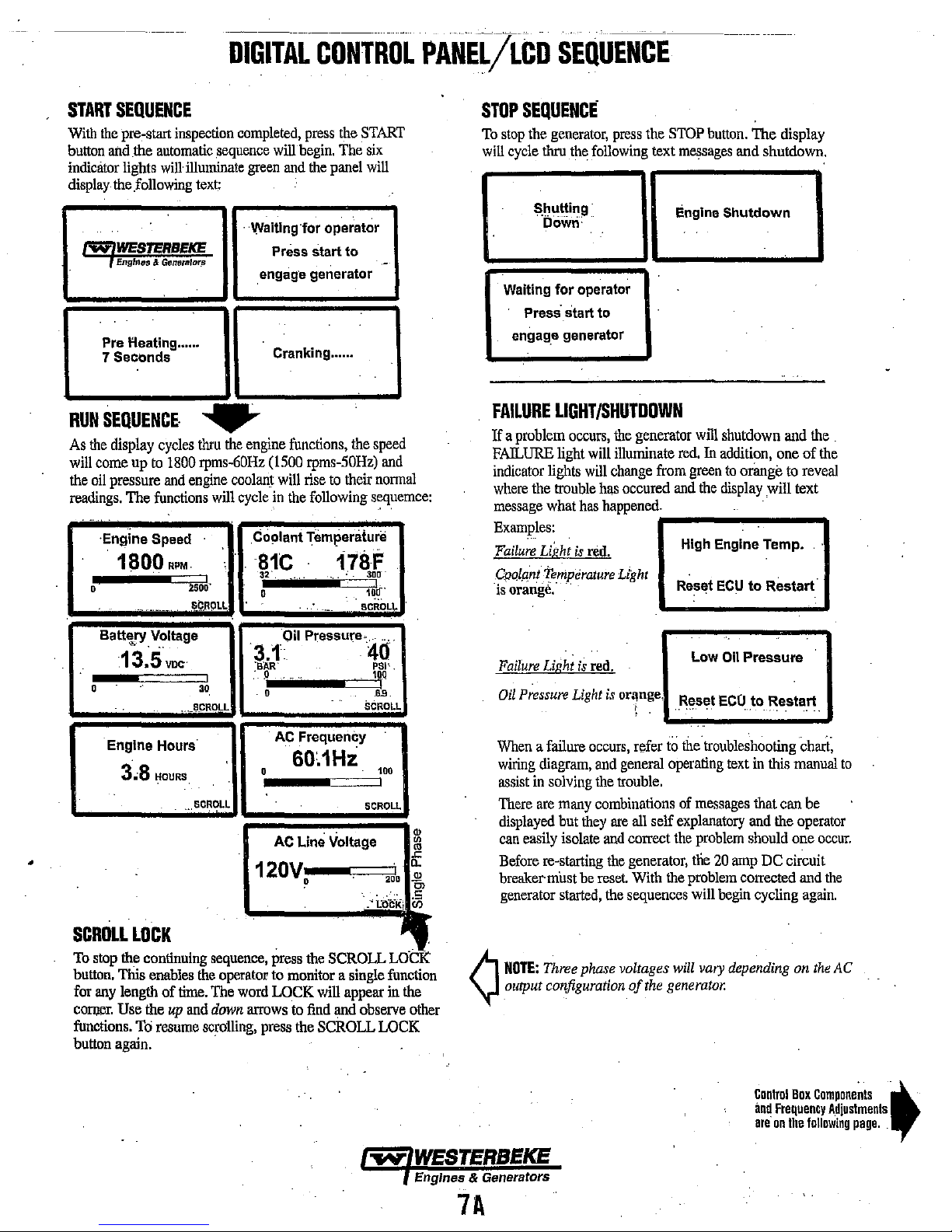
DIGITALCONTROi
PANEilicD
SEQUENCE
START
With
button
indicator
display
SEQUENCE
the
pre,start
and
the
automatic
lights
will
the
following
f'WIWESTERBEKE
, EngInes &
Pre
7 Seconds
RUN
SEQUENCE·
As
the
display
will
come
the
oil
pressure
readings.
'Englne Speed
0
Generalor.s
l'Ieating ......
cycles
np
to
and
The
functions
1800
.'
....
_.
inspection
illuminate
text:
....
thru
1800
rpms-60Hz
engine
RPM
250J,
S¢J~PLl
completed,
sequence
green
. Waiting for operator
the
engine
coolanJ
will
cycle
.Co"lant Temperature
81C
press
will
begin.
and
the
.
Press start to
engage generator
Cr.nking ......
functions,
(1500
rpms-50Hz)
will
rise
in
the
following
32',
0
the
START
The
six
panel
will
-
the
speed
and
to
their
nonnal
sequemce:
17~f.
!
1~tr·
SCROLL
.
-._-
STOP
SEQUENCE
To
stop
the
generator,
will
cycle
thru
the
following
Shutting'
110w,;'
Waiting
Press'
engag.e
FAILURE
If
a
problem
FAILURE
indicator
where
the
message
Examples:
Failure
Light
CPQl.aill;Temperature
"is
orange,"
..
for
operator
start
generator
LIGHT/SHUTDOWN
occurs,
light
will
lights
will
ttouble
what
has
is
red.
.
press
to
the
generator
illwninate
change
has
occured
happened.
Light
the
STOP
button.
text
messages
Engine Shutdown
will
shutdown
red.
In
addition,
from
green
and
the
display
High Engine Temp.
Reset
ECU
The display
and shutdown.
and
one
to
orange
to
will text
.
to
Restart'
the
of
the
reveal
.
•
Batt\ry
0 30
SCROLL
To
stop
button.
for
any
COfl)!lr.
functions.
button
Voltage
13.5voo
Engine Hours
3,8
HOURS
LOCK
the
continuing
This
ellllbies
length of
Use
the
To
resume
again.
,._I:l.CROLL
."
time.
up
and
!
SCROLL
sequence,
the
operator
The
down
scrolling,
.
3.1
·B:A.R'
"
0
120V
word
arrows
press
Oil
Pressure." ' ..
.0
0
.
AC
Frequency
60,1Hz
AC
Line Voltage
o
press
the
to
monitor a single
LOCK
will
to
find
the
SCROLL
40
PSI'.
1Q.Q
.6~9
.
SCROLL
100
!
SCROLL
~i
~~i<;
TTl
function
appear
in
and
observe
LOCK
.
the
other
Failure
Oil
Pressure
When
a failure
wiring
assist
in
There
are
displayed
can
easily
Before
breaker'
generator
A
NOTE:
\l
output configuration
Light
is
Light
diagram,
solving
many
but
they
isolate
re-starting
must
be
started,
Three
phase voltages
red.
is
or~nge.
occurs,
refer
and
general
the
trouble.
combinations
are
all
self
and
correct
the
generator,
reset.
With
the
sequences
of
the
Oil
ECO
20
begin
vary
Pressure
to
text
in
that can
and
should
amp
corrected
cycling
depending
Low
Reset
to
thetroubleshooting
operating
of
messages
explanatory
the
problem
tlie
the
problem
will
will
generator.
Restart
this
manual
the
one
DC
circuit
on
chari;
be
operator
occur.
and
the
again.
the
AC
to
"'loY'
WESTERBEKE
Engines & Generators
7A
Conlrol
and
Frequency
are
on
Box
Components
Ihe
following
pag
t
•.
Adjustments.
'.
Page 15
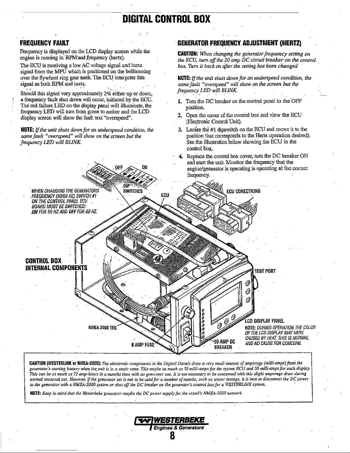
DIGITAL
CONTROL
BOX
FREQUENCY
Frequency
engine
The
ECD
signal
from
over
the
signal
as
Should
a
frequency
The
red
frequency
display
NOTE:
If
same
fault
frequency
.
WHEN
.
FREQUENCY
ON
BOARD
.ON
is
displayed
is
running
is
receiving a
the
flywheel
both
this
signal
fault
failure
LED
screen
the
unit shuts
"overspeed"
LED
CHANGING
THE
CONTROL
MUST
FOR
50
FAULT
MPD
RPM
LED
will
will
will BUNK.
(50160
BE
HZ
on
in
·RPMand
low
which
ring
gear
and
hertz.
vary
approximately
shut
down
on
the
turn
from
show
the
down
will
THE
GENERATORS
HZ)
SWITCH
PANEL
SWITCHED:
AND
OFF
FOR
the
LCD
frequency
AC
is
positioned
teeth.
will
display
green
fault
for
show
ECU
60
display
voltage
The
ECD
2%
occur,
panel
to
text
"overspeed".
an
underspeed
on
the
#1
HZ.
screen
(hertz).
signal
on
the
interprets
eit\ler
initiated
will
amber
screen
while
and
hertz
bellhousing
this
up
or
down,
by
the
illuminate,
and
the
LCD
condition,
but
the
the
ECD.
the
the
GENERATOR
CAUTION:
the.
ECU,
box.
Tum it back
NOTE:
If
same
fault "overspeed"
frequency
1.
Turn
FREQUENCY.
When
changing
tum
off
on
the unit
LED
the
DC
shuts
will
breaker
.position.
2.
Open
the
cover
(Elec.tronic
3.
Locate
position
See
control
4.
Replace the
and
Control
th"·#1
that
corresponds
the illustration
box.
control
start
the
unit.
engine/generator
frequency.
the
20
amp
after
down
will
BUNK.
on
of
the
Unit).
dipswitch
below
box
Monitor
is
operating
ADJUSTMENT
the
generator frequency setting
DC
circuit
the
setting
has
for
an
underspeed condition,
show
on
the
lhe
control
control
box
and
on
the
ECD
to
the
Hertz
showing
cov.er,
tum
the
frequency
is
operating
(HERTZ)
breaker on
been changed
screen but
panel
to lh.-OFF
view the
and
move
operation
the
ECU in
the
DC breaker
that the
at ihe
.
the
control
th.e
ECD
it
to
the
desired).
the
ON
COlTect
on
the
CONTROL
INTERNAL
CAUTION
generator's
This
normal
to
NOTE:
BOX
COMiPONIENTS
(WESTERLINK
starling
can
be
as
tleasollal
the
generator
Keep
ilJ
much
use.
with
mind
or
NMEA-200D):
battery
when
as
72
amp-hours
However,
a
NMEt\.200q
that
the
Westerbeke
rhe.,unir
if
the
The
electronic
is
in
in a monrhs
generator
,Iystem
or
gellerator
Q.
static
time
set
is
shllt off
maybe
components
Slate.
This
with
no
not
to
be
the
DC
the
DC
~
in
rhe
Digital
as
much
use.
number
the
generator's
Diesels
as
It
js
not
ofmomhs,
50
the
maybe
generator
used
for a
breaker
~n
power supplyJor
WESTERBEKE
Engines &
Generators
draw
a very
milli·amps for
necessary
vessel)'
such
control
N1v1EA·2000
to'
as
box
small
the
system
be
concerned
willter
for
a
WESTERL/NK
amount
storage,
network.
of
EeU
with
it
DISPLAY
NOTE:
DURING
OF
THE
LCD
CAUSED
BY
AND
NO
CAUSE
amperage
and
50
milli·ampsfor
this
slight
is
best
to
system.
PANEL
OPERATION
DISPLAY
MAY
HEAT.
THIS
IS
FOR
CONCERN.
(milli·amps)frQm
amperage
disconnect
each
draw
the
DC
THE
COLOR
VARY.
NORMAL
the
displ.ay.
during
power
.
8
Page 16

-~~-'
---
------
DESCRIPTION
A
remote
panel
is
availa1:>le
and
started
stopped
connecting
of
these
NOTE:
WESTERBEKE
harnesses
can
For
additional
REMOTE
from
be
combined
dealer.
3-1/4"
(B2.ij5Mn~1
PANEL/PIG
that
allows
any
location
come
in
three
for a maximum
information,
TA
Il
REMOTE
AND
EXTENSION
the
generator
on
the
boat The
different
contact
run
your
lengths
at
75'
local
STOP/START
HARNESSES
to
be
and
two
(22.17M).
6"
PANEL
(152.4MM)
CONNECTING
CABLES'
15'
(4.75M)
3~'
(9.1M)
60'
(1B.2M)
EXTENSION
PN
052959
PN
052789
PN
052960
PN052560
~
....
l""~
These
two
dimensions
are
the
measurement
of
the
cut-out
opening
.
Engines ,i."q",".rators
8A
Page 17

DESCRIPTION
Although
hour of
assembly
operated
life
operated and
Breaking-in a
piston
and
glazed
engine
Your
conditioning
to
Perform
following:
Start
section.
water
AFTER
Once
tion
between
your
test
operations
procedures
properly, a break-in
of
your
engine
serviced
new
rings
to
smoky
operation
or
scored,
during
new
engine
operation
maximize
this
the
engine
Run
pump,
the
conditioning
the
oil
START·UP
the
generator
and
then
encourage a fast
20%
engine
is
engine
the
cylinder
which
the
break-in
requires
performance
according
engine
pressure,
has
and
60%
has
experienced a
at
the
factory
were
followed
time
dependent
during
its
basically
walls.
indicate that
is
caused
period.
approximately
to
break in
and
carefully,
to
the
while
checking
battery
been
started,
warm-up.
of
full-load
GENERATOR
minimum
to
make
sure
and'
that
the engine
is
required.
upon
how
initial
involves
Excessive
the
cylinder
by
overloading
each
service
keeping
STARTING
charging)
check
for
the
hours
of
seating
oil
50
hours of
moving
life of the
in mind
PROCEDURE
that
all
are
for proper
Run
the
the
first
The
engine
use.
consumption
walls
systems
functioning.
10
BREAK-IN
of
one
accurate
service
is
the
are
the
initial.
part in
order
engine.
the
(raw
opera-
generator
hours.
PROCEDURE
After
the
first
10
hours of
can
be
increased
cally
vary
Avoid
overload
exhaust
the
the
rpm
Hertz),
current
NOTE:
draw
draw
with
current
generator's rating.
to
produce
control
drawn
Be
requiredfor starting
can
GENERATOR
GENERATOR
Once
the
governor
the
engine's break-in period
period
see
ENGINE
may
also
adjustment
to
the
full-load
the
load
at
all
times.
reduced output
being
drawn
Since
60 hertz
of the generator's break-in is governed
from the
aware
of
motor
be 3 to 5 times
INFORMATION
ADJUSTMENTS
generator has been
adjustments
ENGINE
ADJUSTMENTS
be
required in
see
required
SPEED
GENERATOR
the
generator's
rated
An
overload
voltage
from
the
the
generator
(or
at
1500
generator.
starting
motors.
normal
placed
for
(first
(HERTZ)
..
A
no-load
conjunction
INFORMATION.
operation,
output,
is
signaled
and
frequency.
generator
and
operates
rpm
to
produce
loads
and
This
starting amperage
running
in
this
manual.
in
operation,
amperage.
engine speed
50
hours)
the
or
then
keep
high
after
the load
periodi-
by smoky
Monitor
at
50
there
(hertz)
this
ADJUSTMENT) under
voltage
adjustment
with the engine's speed
it within
1800
by
the
current
See
may
during
be
CHECK
Follow
•
•
•
•
•
•
•
•
CHECK
•
LIST
this
Check
in
the
off
Record
relate
to
Any
deficiency
be
corrected
Visually
Check
Check
Check
Check
Check
WITH
Check
blow-back
•
Confirm
When
When
When
check
that
position
the
the
inspect
the
the
your
the
drive
for
exhaust
the
the
the
engine
engine
engine
all
hourmeter
oil
coolant
starting
abnonnal
sounds.
list
each
generator
before
reading
maintenance
or
problems
before
start
the
engine
level
(dipstick).
level
fuel
supply.
batteries
belts
for
wear and
THE
ENGINE
noise
smoke:
is
cold - White
is
warm
is
overloaded -
day
before
circuit
starting.
in
schedule.)
in
up.
for
i~
the
(weekly).
RUNNING.
such
- almost
starting
breakers
your
the
followil1g
fuel,
oil,
coolant
proper
as
knocking,
Smoke.
Smokeless.
some
THE
your
(power
log
(engine
or water
recovery
tension
Black
DAILY
generator.
panel)
hours
items
must
leaks.
tank.
(weekly).
vibrating
Smoke.
are
and
ROUTINE
NOTE:
Some
unstable
This
condition
is
reached
A
periods
and
CAUTION:
of
time
generator.
STOPPING
Remove
the
generator
temperature,
generator
safety
CAUTION
Digital Diesels draw a very
the
generator',SlStatting
maybe
. for
each
I: with
amperage draw during nonnal seasonal
set
is
best
to
."
system or
:
WESTERLINK
. .
NOTE:
supply for
THE
the
AC
to
then
is
shutdown,
precaution.
(WESTERLINK
as
much
display.
no
generator
not
to
be used for a
disconnect the
shut
off the
system.
Keep
in
mind that
the
vessel:S-
running
should
abate
loads
are
applied.
Do
not
operate
without a load
GENERATOR
loads
from
run
for
3-5
tum
the
close
or
NMEA-20DO):
small
battery
as 50
milU-amps
This
can
be as
use.
It
is
not necessary to be concerned with this slight
number
DC
power
DC
breaker
the
Westerbeke
NMEA-2000
may
as
normal
the
generator
minutes
key
to
down
amount
when
the
for
the
much
as 72 amp-hours
of
months,
to
the
on
the generator's
network.
occur
in a cold
operating
the
generator
being
placed
one
to
stabilize
the off
position
all
circuit
breakers
The
electronic components
of
amperage (milli-amps)
unit
is
in
system ECU
use.
generator
generator
a static state. This
and
However,
such
as
winter storage,
with a NMEA-2000
control
maybe
engine.
temperature
for
long
on
the
at
a time.Allow
the
operating
..
Once the
as
50
milli-amps
in
a months
if
the
generator
box for a
the
DC
a
in
the
from
time
it
power
.
.
is
Engines & Generators
9
Page 18

A
WARNING:
running.
use
the
servicing
NOTE:
Many
difficult
and
Wear
the
correct
any
of
of
the
may
MAINTENANCE
Never
attempt
proper
tools
for
the
engine's
following maintenance jobs
require
the expert
safety
each
DC
to
perform
equipment
job.
Disconnect
electrical
knowledge
SCHEDULE
any
service
such
as
the
battery
equipment.
are
simple
of
a service
while
goggles
terminals
but others
mechanic.
the
and
engine
gloves,
when
are
more
is
and
SCHEDULED
MAINTENANCE
Fuel
Supply
Fuel/Water
Engine
Coolant
Drive
Visual
Separator
Oil
Level
Level
Belts
Inspection
.
Fuel
Filter
SiartingBatieries,
'(a~d
House,Batteries)
Engine.oil
.
,
Generator
Heat
Fuel
(and
Exchanger
Filter/Water
of
Engine
filter)
Zinc
Anode
Separator
CHECK
EACH
DAY
D
D
D
D
D
weekly
D
D
weekly
HOURS
OF
OPERATION
100
250
500
750
50
NOTE:
and
oil
remain
Please
will
inhibit
cool.
keep
the
engine
engine's
1000
surface
ability
clean.
to
D D D D D D
, '
D
D
D D
D D D D
D D D D
D
D D
D
D
D
D
D
D
D D D
1250
Dirt
D
D
D
EXPLANATION
Diesel
No.2
Check
for
water
if
necessary).
Oil
level
should
dipstick.
Check
at
recovery
Add
coolant
Inspect
for
and
adjust
Check
for
and
electrical
Check
for
Initial
change
Every
50
operating
and
make
excessive
Initial
engine
change
both
Check
that
with
no
chafing.
for
additional
Inspect
zinc
exchanger
Inspect
daily.
hours
of
use
drain
separator
MAINTENANCE
rating
of
and
dirt
indicate
tank;
if
needed.
proper
tension
if
needed.
fuel,
oil
and
connections.
loose
belt
tension
at
50
hrs,
hours
sure
connections
corrosion
.
oil & filter
every
100
AC
connections
See
information.
anode,
replace
end
of
zinc
Replace
or
as
found
bowl
OF
SCHEDULED
45
cetane
or
higher.
in
fuel
(drain/replace
between
if
Check
water
hours.
GENERATOR
anode
filter
as
empty,
(3/B"
belt
leaks.
Keep
.
then
change
check
are
change
are
clean
if
needed,
debris.
element
to
be
needed.
MAX.
check
to
1/2"
edges
Inspect
bolts
electrolyte
very
at
50
SECTION
needed.
and
LOW
at
manifold.
deflection)
for
wear.
wiring
,&
nuts
every
250
levels
tight.
Clean
hrs.,
then
and
secure
clear
the
every
250
Clean
filter
on
tight.
hrs.
off
heat
and
Text
Removed
Exhaust
System
Engine
Hoses
Inlet
Fuel
Filter
D D
D
D D D
D
D D
Engines & Generators
D D
D
D
D
D D
10
D
Initial
check
the
system
manifold.
and
other
dition.
No
Hose
should
spongy.
Check
Replace
initially
or
as
needed.
at
50
hrs.,
is
securely
System
is
properly
components
leaks.
,be
hard & tight.
and
tighten
at
50
hours
then
every
fastened
supported
are
in
good
Replace
all
hose
and
250
hrs.
to
the
exhaust
and
serviceable
if
soft
clamps.
then
once a year
Ensure
muffler
con-
or
Page 19

NOTE:
Use
engine
hours
MAINTENANCE
the
engine
hour
meter
gauge
to
by
running
time.
SCHEDULE
log
your
engine
hours
or
record
your
SCHEDULED
MAINTENANCE
Raw
Water
Pump
At
80Q
.
operating
disassemble
for
overhauL
Raw
Water
Pump
Air
Inlet
Filter
Coolant
System
Electric
Fuel
DC
Alternator
'Fuel
Injectors
'Starler
'Preheat
'Engine
'Torque
•
'Heat
Motor
Circuit
Cylinder
Compression
Cylinder
Hold-down
Adjust
bolts
the
Valve
Exchanger
and
Lift
hours,
inspect
Drive
Pump
Head
Clearances
CHECK
EACH
DAY
50
0
0
0
HOURS
100
0
OF
OPERATION
500
250
0 0
0
0 0
0
0
0 0
0
0
0
0
0
0
750
0
0
0
1000
0
0
0
0
0
0
0
1250
Remove
0
imp~lIer,
Inspect
seal
should
Remove
slot
Inspect
0
Replace
Drain,
appropriate
various
Periodically
0
inspect
Check
0
bracket;
Check
spray
Check
0
and
pinion
Check
0
clean
Reinstall
Check
0
(see
At
(see
Adjust
(see
Remove,
pressure
EXPLANATION
the
pump
cam,
cover
housing
or
oil
leaks.
turn,
not
pump
for
wear.
every
100
as
needed.
flush,
and
antifreeze
cooling
check
the
fuel
DC
charge
tighten
and
adjust
condition
solenoid
lubricate.
first
ENGINE
Clean
drive.
operation
glow
plugs;
with
anti
compression
Engine
Adjustments).
50hours,
ADJUSTMENTS).
Valve
Clearances
ENGINE
ADJUSTMENTS).
have
tested.
OF
SCHEDULED
MAINTENANCE
cover
and
impeller.
and
inner
wear
weep
holes
for
Check
shaft
bearings
wObble).
and
inspect
pump
hours.
Remove
refill
cooling
system
mixture
compatible
system
metals.
the
wiring
connections
line
connections.
from
alternator.
electrical
(see
and
professionally
injection
ENGINE
motor
and
of
preheat
check
seize
pressure
then
every
connections.
opening
ADJUSTMENTS).
for
corrosion.
lubricate
solenoid.
resistance
compound
and
500
cleaned
plate
signs
shaft
and
Check
pressure
the
(0.4-0.6
on
timing
hours
Inspect
the
for
wear.
of
shaft
water
(the
shaft
and
drive
clean.
with
with
and
mounting
and
Remove
starter
motor
Remove
ohms).
threads.
and
and
'WESTERBEKE
,
-,
c"',
A
DC
components,
I .
tuined
battery
recommends
_
"'7-:_
CAUTION:
When
the
off
using
either
switch.
this
service
be
performed
" •
ser~icingJchanging
DC
power
must
be.
the
DC
breaker
. .
or
".
the
by
an
authorized
Engines &
11
mechanic.
Gene.ralors
Page 20

FUEL
SYSTEM
DIESEL
USE A DIESEL
(No.
FUEL
Th~
manufactured
from
must
separator
clean,
schedule
FUEL
A
installed
water
be
The
fuel
impurities.
maintaining
fuel
a
FUEL
The
of
The
and the owner/operator is cautioned not
it.
authorized
attempt
FUEL
FUEL
2·0
(SAE
J313)
FILTERS
fuel
injection
water
aiJ.d
pass
through at least
and
the engine's spin·on
and
change
in
this
WATER
primary
10
fuel
between
and
other
carried
to
the fuel
owner/operator
reaching
tank
micron
the engine's
This
a proper
and
the
filter
INJECTION
fuel
injection
the
diesel
engine,
fuel
injection
If
it
requires
fuel injection
to
disassembly
WITH A CETANE
diesel
fuel
according
pump
and
1he
and they
dirt.
To
these
manual.
must
ensure
two
filters
receive'
this
fuel
according
SEPARATOR
filter
of the
water
the
fuel
tank
and
contaminants
system
is
process
fuel
generator/engine.
be
used.
from
on
the engine.
responsible
injection
is
accomplished
filter/water
PUMP
pump
is
the
most
requiring
pump
servicing,
the
has
been thoroughly bench-tested
remove
pump
service
and
repair
RATING
fuelinjectors
flow
filters, a fuel
fuel
separating
the engine
the
for
equipment
Westerbeke
utmost
it and
it.
OF
#45
OR
HIGHER.
to
ASTM
0975}.
are
precisely
clean
diesel
fuel,
free
of
clean
fuel,
the fuel
water
filter.
Visually
to
the
type
fuel before
making
separator
important component
certain
by installing and
caution
to
attempt
take
it
facility.
inspect,
maintenance
must be
to
remove
they
can
the
is
free of
between the
recommends
in handling.
to
service
to
an
Do
not
ENGINE
Periodically
leakage.
then
Changing/cleaning
1 .. Shut off
2.
3.
4. Replace
FUEL
Replace
follbw
Unscrew
housing
housing,
Remove
to the
housing.
as
not
so
"0"
ring,
supply
FILTER
check
the fuel
the
filter
the
MAINTENANCE
the
fuel
supply.
the
retainer ring that
and
allow
the bowl
and
replace the
the
sealing
Thread the retainer ring
to
cross
thread.
tighten 1/4 -
and
run
the engine
the
"0"
connections
element
after
SCHEDULE.
filter
element
holds
to
come
filter
element
ring
and
When
1/2
turns
to
inspect
and
the bowl
the first
the filter
away
and
reassemble
on
retainer contacts the
by.
hand.
for
leaks.
50
hours
bowl
from
the
clean
the
carefully
Open
for
to
the
bowl.
bowl
the fuel
the
FUEL
LIFT
PUMP
Periodically
and
make
~etight
pulnp's rriouniiligbolts
the
mOunting
When
purge
qffuel
INLET'
,!,o,ens.ureclean
in-line
check the
sure'that
and
energized
air
frOm·theiuel
as
the
FUEL
fuetfillJ:l:,c,onnected
no
s~ure.
The
bolt
to
ensure
thru
engine
is
FILTER
fpel into
fuel
connections
leakage
DC
should
the
preheat
system
rurriJiug:
the
to
is
present
ground
connection
be clean and
proper
pump
circuit,
and
provide a
fpelliftpump,
to
the
fuel
lift
and
out
and
that
at
well
secured
operation.
the
fuiol1iftpump
continuous
'.
there
pump
elbow.
of
the
the
fitiings
one of the
"
flow
' ,
is a
small
,
~
pump
THE
O·RING
ONLY
by
will
'
REPLACES
SIGNS
WESTERBEKE
Engines & Generators
GASKET
NEEDS
TO
IF
IT
OF
AGING.
FUEL
FILTER
FUEL
PN#052853
BE
SHOWS'
LIFT
PUMP
12
Page 21

DESCRIPTION
Westerbeke
for
fresh
bustion
which
water
parts,
from
exchanger,
water
marine
water
and
friction
circulates
coolant
and
the
the
fresh
similar in
flows
through
cooling.
throughout the
cools
engine
water
diesel
Heat
is
transferred
the
engine
oil.
The
co01ant
function
the
tubes
engines
are
produced mille
to
fresh
engine.
block,
heat
is
transferred
to
raw
water
to
an
automotive
of
the
heat
-............-
designed
water
This
its
internal
by
exchanger
----
COOLING
and
equipped
engine
by
com-
coolant
circulating
externally
means
radiator.
fresh
moving
of a
heat
Raw
while
.
-----.:...
--.
SYSTEM
fresh
water
coo
ferred
to
the
tube
walls
to
exhaust
other
coolant
transferred heat
fresh
each
allows
harmful
system
words,
is
water
other.
the
deposits.
cooled
coolant
Using
cooling
hint
fresh
the
raw
where
the
engine
by
overboard
only
flows
water
water
raw
and
water
around
coolant
finally
is
cooled
water,
through
raw
fresh
passages
the
tubes;
engine
is
conducted through the
which
is
then
pumped into the
it
is
discharged overboard. In
by
fresh
water coolant, this
and
the
raw
water
the
exhaust system. The
water
circuits
water
to
are independent of
coolant
within
stay
clean
heat
carries the
the
engine
and
free from
trat]s-
INCOMING
COOLING
DIAGRAM
FRESH
CIRCUIT
WATER
RAW
WATER
RAW
(TYPICAL)
¢
..
NOTE:
VALVE
FRESH
DRAIN
AN
ANTI-SIPHON
MAY
HEAT
EXCHANGER
WATER
BE
REQUIRED
.....
WESTERBEKE
Engines & Generators
13
WATER
DRAIN
Page 22

···CootINGSYS-TEM
FRESH
NOTE:
WATER
Refer
ommended
fresh
water
Fresh
water
circulating
coolant
to
enginl'
When
prevented
flow
manifold
thermostat
coolant
cooling
RECOVERY
Ihen
the
heat
exchanger
block
the
engine
by
is
bypassed
from
to
flow
system.
TO
COOLANT
TANK
FROM
COOLANT
RECOVERY
TANK
COOLING
to
the
ENGINE
antifreeze
coolant.
coolant
pump,
absorbing
passes
via
the
is
the
closed
around
overheating).
gradually
umestricted
and
water
is
pumped
through
where
suction
started
thermostat
the
opens,
CIRCUIT
COOlANT
mixture
through
heat
from
the
thermostat
it
is
cooled,
side of
the
cold,
external
(allhough
thermostat
As
the
engine
allowing
to
the
external
KEEP
THE
COOLANT
section
to
be
used as
the
engine
Ihe
engine.
into
and
returned
circulating
coolant
some
to
prevent
warms
full
flow
of
portion
PASSAGE
PRESSURE
yCAP
for
by
The
the
manifold,
pump.
flow
coolant
the
up,
the
of
the
rec-
the
a
to
the
is
exhaust
the
engine's
the
CHANGING
The engine's
MAINTENANCE
become
A
COOLANT
coolant
SCHEDUlE.
contaminated,
CAUTION:
Proper
critical; a SUbstantial
.
traced
bilCk
to
cooling
Drain
the
engine
coolant
engine
block
and
opening
the
system
with
fresh
the
refill
process.
NOTE:
Tlte
drain
petcock
be
used
to
drain
must
be
it
can
cooling
number
system
by
the
water,
on
engine
changed
If
Ihe
lead
to
overheating
system
of
engine
corrosion
removing
manifold
then
reinstall
the
heat
coolant.
according
coolant
is
maintenance
failures
•.
the
drain
pressure
the
draio
exchanger
COil
.'
/"LLI'"
to
the
allowed
problems.
can
plug·on
cap.
Flush
and
should
also
LAliT
DRAIN
HD
PLUG
to
is
be
the
start
6MM
NOTE:
Periodically
pressure
good
the
closes
cap.
coolant
coolant
able
to
Coolant
The
traction
out
provided
water
operating
NOTE:
located
cap.
condition.
vacuum,
valve opens and
tightly.
Check
also
passage
within.
to
expand
andfron'/.
the
Recovery
coolant
recovery tank
of
the engines
introducing
with
coolant conversion kit
the
Tltis
tank,
at or
above
check
the
Ensure
the
upper
Check
to
ensure
Cony a
spare
to
ensure
the
is
clear
so
the,
system
is
and
contract
coolant reCaVel)1
Tank
coolant
air
into
the
fresh
water
cooled
engine.
with
its
slWI1
the
level
COOLANT
RETRACTION
condition
and
lower rubber seals are
tank.
allows
for
dnring
system.
This
models
and
must
run
of
of
the
engine ~ manifold.
of
the
manifold
the
expansion
engine
operation
recovery tank is
and
with
be
installed before
plastic
hose,
and
Witll-
the
fresh
is best
con-
in
Refilling
. After
exchanger's
slowly
Monitor the
the manifold to the filler
pressure
Remove
coolant Inix
the
flow
After
Coolant
engine
needed and
spilled
AIR
Clean
top
functions:
provides
The
be
clear
periodically
obstruction.
the
Coolant
replacing
pour
cap.
into
checking
cools
coolant.
coolant
clean,
coolant
cap.
the
cap
to
Run
the
should
check
the
engine
premixed
on
the
halfway
the
engine
ricovery
for
leaks,
draw
down.
Add
the
petcock.
in
INTAKE/COOLING
air
is
drawn
into
side
of the
generators
it
cools
the
clean
fresh
generators
from
be
air
intake
obstruction
inspected
c\
block
coolant
the
manifold
neck
coolant
between
and
observe
tarik.
stop
back
into
coolant
coolant
the
engine
backend.
electronics
air
for
engine
must
and
to
be
drain
Then
and
install the
recovery
LOW
the
engine
the
to
in
the
Ihrn
in
have
the
air intake
sure
run
the
engine
into
the
manifold.
and
add
as
manifold
tank
and
and
MAXand replace
the
coolant
and
allow
cooling
the
combustion.
system
recovery
manifold.
the
air intake at the
The
air
the
control
"breathing
it is
also
serves
hose
free
heat
at
idle
needed.
fill
with
expansion
it
to
as
the
tank
if
Clean
up
two
box
and
space"
should
from
and
Fill
cool.
any
and
Engines &
14
A
CAUTION:
with
the
Generators
Never
generator
running.
perform
air
intake
maintenance
Page 23

THERMOSTAT
A
thermostat,
engine,
continuously
the
engine
coolant
hole
in
overheating).
gradually
checked,
and
gasket
Replacing
Remove
housing
gasket,
gasket
cap
screws.
Run
the
there
are
controls
is
from
Ihe
Ihermostat
opens.
cleaned,
the
cap
as
shown.
apply
before
engine
no
leaks
located
the
coolant
flows
through
first
started,
flowing
As
the
(some
Ihe
engine
The
Ihermostat
or
replaced
Thermostat
screws
When
a thin
coat
pressing
and
check
at
the
near
the
temperature
the
the
closed
coolant
to
prevent
wanns
and
disassemble
installing
of
sealant
it into
for
thermostat
manifold
closed
thermostat
is
1he
up,
is
accessible
easily.
the
on
place.
DO'
nornrnl
housing.
at
the
front
as
the
coolant
cooling
circuit
prevents
by-passed
exhaust
manifold
Ihe
Ihermostat
and
Cany a
the
new
thermosta1
both
sides
not
over-tighten
spare
thermosta1
ternperatores
of
tlie
When
1j:rrough
from
can
be
Ihermostat
and
of
the
1he
and
that
RAW
WATER
NOTE:
Alw~s
the
strainer
A
clean
a
engine's
strainer
in
Ihe
glass
Perform
INTAKE
install
will
always
raw
water
cooling
when
making
should
the
fOllowingmamtenance
STRAINER
the
strainer
be
intake
system.
Include a visual
your
be
clear.
strainer
at
or
below
self-pliming.
is a vital
periodic
engine
after
the
waterline
component
inspection
check.
every
100
of
The
hours
of
Ihe
this
water
of
so
,
operation:
L
Close
the
2.
Remove
3.
Clean
4.
Replace
5.
Reassemble
6.
Open
7.
Run
NOTE:
Also
Ihe
the
the
and
the
engine
follow
raw water
clean
glass.
washer
and
seacock
install
and
the
seacock.
Ihe
strainer
if
necessary.
the
..
check
above
'
filter.
strainer.
for
leaks.
procedure
after
haviJ'g
TUn
hard
aground.
If
the
engine
normal
may
have
raw
water
temperature
reading,
been
through
Ihe
caught
cause
the
gauge
may
up
in
the
cooling
ever
shows a bigher
be that
strainer,
system.
silt,
leaves
slowing
or
the
than
grass
flow
of
I-~''!'-''=.~~:~
FOR
COOLING
GASKET
USEHI-TACKSEAf.ANT
PETCDCK
PUSHING
AIR
FROM
SYSTEM
PN#036956
THERMOSTAT
ASSEMBLY
THE
STI)A,INER
~I~TER
_-"'"liS'
INCOMING
RAW
WA1'tR-
SEACOCK
TYPICAL
(OWIIER
.......
I',!
---'7>""_
INSPECTAND
CLEAN
EVERY
100
HOURS
RAW
WATE;R~~;
INSTALLED)
~
WESTERBEKE
EngInes & Generators
15
Page 24

RAW
WATER
The
raw
impeller
ocean,
lake,
the
water
to
through
exchanger
water
coolant.
water-injecte4 exhaust
exhaust
driven
thruugh
HEAT
EXCHANGER
Cool
raw
exchanger.
the heat of the internal
which
is
charged.
through
NOTE:
Operating
that a
heat
every
1000
CODLING
water
flow
pump.
TIns
or river from a
strainer.
the
pump
tubes)
The
gasses.
T1:rls
the
water
flows
As
the
then
pumped
The
engine
the
engine
exchanger
hours.
is
pump
The
to
where
raw
nrlxture
stem
engine
coolant
and
in
silty
CIRCUIT
created
draws
thru-hull
raw
the heat
it
cools
water
elbow,
tube
through
coolant
engine
into
the
(now
the
circuit
arullor
cleaning
by
a positive displacement
water
directly
opening
water
passes
exchanger
the
engine's
is
then
discharged
mixing
of
exhaust
and
overboard.
the
inuer tubes of
passes
is
conducted
exhaust
cooled)
repeats
tropical
be
peifol7ned
Witll,
from
(through
circulating
and
gas
and
around
to
system
flows
itself.
waters
through
the
and
more
COOLING
SYSTEM
RAW
The
from
the
the
strainer
the
heat
into
the
cooling
raw
water
the
heat
these
raw
dis-
back
may
require
often
a hose
fresh
the
is
tubes,
water
then
non-ferrous
has
within
On
always
(an
wheo
operation.
are
start-up.
periodically
MAINTENANCE
NOTE:
(seals
purchase a new
a
Changing
Close
and,
carefully
inlpeller
curved
ing.
the
WATER
raw
fle«ible
the
no
acconn! should this pump be run
be a spare
inlpeller
lubricant
cautioned
water
housing
blades
inlpeller
kit).
Such
The
raw
for
PUMP
pump
and a Neoprene
which
housing,
inlpeller
Raw
(raw
water)
failures
to
make
water
broken
is
a
self-priming,
wipe
and
water
is
are
not
sure
raw
pump
or
tom
producing
pump
not
should
SCHEDULE.
Should a failure
ami
bearings),
pump
occur
it
may
alld
with
be
rebuild
spare.
the
Raw
Water
fue
raw
using
pry
and
carn
When
inlpeller
water intake
an
impelle,
the
inlpeller
gasket.
plate
and
assembling,
and
gasket.
valve.
puller,
out
Move
fue
push
the
apply a thin
Opeo
screw
of
rotary
inlpeller_
against
a curved
the
inlpeller
warrantable,
water
impeller
nwre
Pump
blades
inlpeller
the
inlpeller
present
flow
be inspected
the
pumps
cost
the
original
Impeller
Remove
drivers,
the
pump.
to
coating
raw
water
cover
blades.
COnfOffil
into
pump with a
The
inlpeller
caro
pumping
dry_
There
gasket
failures occur
during
engine
and operators
is
present at
See
.
internal parts
efficient
to
pump
the
pump
or
pliers,
Install
the
to
fue
pumps
of
lubricant
intake
valve.
plate
action.
should
aboard
as
cover
new
the
hous-
to
HEAT
EXCHANGER
CLEAN
OUT
ZINC
ANODE.
A zinc
anode,
circuit
witl:rln
anode
is
to
in the
raw
water cooling
of
electrolysis
condition of
the
anode
cleaned
should be
NOTE:
and
NOTE:
not
insulate
1wusing
carried
ELectrolysis
vesseL
The
threads
require
the
preventing
BOTH
ENDS
or
pencil,
the
heat
sacrifice
on
other
the
zinc
or replaced
on
is
Location;
of
sealant.
zinc
from
~"1l'i~=::.--
-/"'''AN
is
located
in
the
exchanger.
itself
circuit,
componeots
anode
board.
the
result
1Wt
thot
the
zinc
Sealant
the
electrolysis
to
electrolysis
thereby
should
as
of
of
the
atwdes,are
should
metal
of
action
The pwpose
of the
be checked
required.
each
engule.
not
tIle
'HAW
WATER
OUT
DEBRIS
CLEAN
REUSE
raw
water cooling
of
the
action
taking
reducing the effects
system.
Spare
pa/ticular
pipe
be
used
The
monthly
anodes
instalLation
threads
as
it
may
heatexc/wnger
on
the
zinc.
DRAIN
DRAIN
AND
zinc
place
and
WU}
do
.
A
CAUTION:
impeller,
cooling
they
circuit.
exchanger.
INSPECTIDN:
EACH
REPLACE
ANY
CHECK
BLADE
BY
THE
CRACKS.
If
any
must
They
THE
BASE
BENDING
IMPELLER
IF
THE
PIN
SLOT
LIGHTLY
PUMP
AND IMPELLER
GLYCERIN.
INSPECT
AND
IMPELLER.
IF
THEY
OF
WEAR.
of
the
vanes
be
found
to
often
can
be
OF
VIGOROUSLY.
THERE
ARE
FITS
INTO
IN
THE
GREASE
CHAMBER,
THE
SHOW
THE
SHAFT.
THE
O-RING,
WITH
Q-RING
REPLACE
SIGNS
have
prevent
blockage
found
broken
in
the
heat
off
in
the
the
Engines & Generators
16
Page 25

- -
---
--------~---~~
ENGINE
1.
OIL
Drainulg
the
sump
while
the
replace
the
CHANGE
the
Oil
drain
hose
engine
hose
securely.
NOTE:
Thread
size
is
114NPT.
Always
yellow/gray
the
prompt
qualified
Raw
the
siphoning
circuit
is
poor
2. Replacing the Oil
filter,
in
the
helps
should
NOTE:
filter
Place
filter
(Oil
cooling
oil
sealing
rubber
bracke~
oil.
Although
water
exhaust
into
often
location
you
the
upper
oil
from
to
be
Do
to
some
when
or
any
filter
sealing
observe
emulsion
attention
mechanic
present
system
of
raw
the
exhaus~
caused
by
or lack of
may
find
and
it
into a container
lessen
spillage. A small
helpful
IIOt
punch
nui.ke
certain it
paper
unscrewing
other
abiJi1y.
Keep
as
it is
removed
gaSket
comes
gasket
gently
remove it.
the
Sump.
Discharge
(attached
is
warm.
in
its
bracke~
for
the
used
indicates
this
condition
to
prevent
should
in
the
attached
water
the
absence
Drain
lube
oil
as
serious
water
oil
can
to
through
filling
to
the
and
oil
it is
the
is
the
the
of
maintenance.
Filter.
When
it
helpful
and
lower portion of
before
in
removing
this
towels
fiuid
your
off
remains
on
the
lrole
witlrout
can
be
renroved.
and a plastic
it
to
catch
the
engine
engine
to
make
with
the
sealed
ENGINE
the
used
oil
through
the
front
of the
engine)
used
oil
completely,
replace
drain
rare,
be
be the
engine
the
engine.
an
removing
cleaner
the
automotive
old
any
clean.)
sure that the rubber
old
the
hose
removed.
presence
it
does
damage.
present
result
andlor
raw
water
This
anti-siphon
the
to
old
filter
removing
oil
filter.
first
loosening
bag
around
oil
left in
reduces
Inspect
oil
filter.
against
end
capped
A
of
water
require
Call
in
the
of a fault
cooling
problem
valve,
used
punch-a
to
it.
filter
the
the engine's
If
the
filter
LUBRICATING
When
gasket's
apply
on
cap
end
in
a
oil.
a
oil
hole
drain
This
wrench
the
the
filter.
the
old
this
in
its
filter
filter
NOTE:
through
A
contaminants.
and
discard
used
NOTE:
matedal
generic
parts.
run
and that
3.
Filling
-cap
After
checking
around
stop
lube
the
OIL
installlng
sealing
a
thin
coat
the
new
oil
nipple
on
finnly
by
TI,e
engine
passages
WARNING:
Avoid
nails
thoroughly
clothing
oil
properly.
Genedc
standards
parts
might
Irmnediotely
the
engine
there
the
Oil
on
the
top
refilllng,
the
oil
the
new
the
engine.
oil
dipstick.
dipstick,
should
the
surface
of
clean
filter.
the
oil
hanel.
oil
in
Used
prolonged
using
or-
rags
filters
or
after an
to
make
are
110
Sump.
of
the
run
the
pressure.
oil
filter
Then
Fill
new
oil
on
the
engine
Screw
the
filter
bracket,
is
cooled
the
oil
filter
engine
soap
containing
are
not
diameters
be
entirely
sure
oil
leaks
Add
engine
engine
Make
or
check
to,
but
the
engine
filter
element,
bracket
oil
filter
free
to
the
onto
and
by
engine
bracket
oil
contains
skin
contact.
and
water.
used
recommended,
of
important
different
oil
filter
change
the
oil
pressure
around
the
new
oil
through
or
through
for a few
sure
there
from
the
oil
the
quantity
not
over
the
require
additional
.as;;;=::::",
wipe
of
oil
rubber
the
threaded
then
tighten
coolant
housing
harmful
Clean
Launder
oil.
Discard
as
the
items
from
genuine
and
is
nonnal
new
oil
the
oil
the
side
moments
is
no
drain
system,
of
oil
with
high
mark
PN#036918
SPIN·ON
TURN
ON
the filter
and
gasket
oil
the
flowing
assembly.
skin
or
oj,
oil fill,
filter.
filler
oil
fill.
while
leakage
and
the
on
oil.
DlL
FILTER
HAND
TIGHT
LUBRICATION
OIL
OIL.~~~;SSljRE-~rnll~..,.
SWITCH
OIL
FlLTIER--~
OIL
PRESSURE
RELIEF
OIL
DIAGRAM
PRESSURE
VALVE
PUMP
OIL
DRAIIN
--->
SEALING
.APPLY
Engines & Generators
·1~,~;t;~~~~mi1l1~11(
';,
17
TO
OIL
DRAIN
UP
THRU
USING
THE
OIL
THE
AN
BMM
OR
HOSE.
(11/16')
PUMP
SOCKET
THE
WARMED
FOR
EXTENSION
114"NPT
Page 26

REMOTE
OIL
FILTER
(OPTIONAL)
INSTALLATION
This
popular
filter
from
an
engine
NOTE:
instructions
APPLY A THIN
INSTALLING
TIGHTEN
CONTACTS
the
roorri
Refer
THIS
AN
ADDITIONAL
THE
accessory
engine
bulkhead.
to
ENGINE
on
removing
COAT
OF
CLEAN
KIT:'I!lREAO
BASE.
is
to a more
DlL
THE
3/4
TURN
used
to
relocate
conveniept location
OIL
CHANGE
the
oil
filter.
TO
THE
O-RING
KIT
ON,
THEN
AFTER
THE
O'RING
PN:040078REMOTEOiL
To
install,
the
engine's
such
oil
as
WESTERBEKE's
install
Contact
in
this
manual
for
NOTE:
incorrect
A
rectly.
pass
from
failure.
immediately
WHEN
HAND
.
F1LTERSET
simply
.
remove
remote
this
kit with
your
Westerbeke
installation
CAUTION:
If
the
valve
reaching
If
the
oil
WESTERBEKE
is
not
of
.It
is
Oii'f,ows
in
the
filter
the
engine
there
is
no
and
check
the
engine
oil
filter
filter
facing
dealer
responsible
the
Remote
vital
to
install
in
the
reverse
assembly
causing
011
pressure
the
hose
oil
filter
and'
kit
as
shown.
down
as
illustrated.
for
more
information
for
engine
failure
Oil
Filter.
the
oil
lines
directiDn,
will
prevent
an
intemal
reading,
shutdown
connections.
FASTEN
SECURELY
(SCREWS
ARE
thread
on
Always
due
to
cor·
the
by·
the
Dil
engine
TO A BULKHEAD
OWNER
SUP~LlEO)
NOTE
THE
ON_THE
ADAPTER
REMOVED
FOR
WILL
BE
RECONNECTED
'
MARKINGS
WHEN
THE
INSTAllATION
HOSES
C.0RRECTLY
SO
ARE
THEY
'THE
IN
CONNECTION
:
MUST
ATTACH
CONNECTION
/ne",u',e
Oil
CONNECTION
REMOTE
DlL
TO
THE
AT
THE
FILTER.
TO
THE
ATTHE
FILTER.
HOSE
OUT
IN
APPLY A THIN
G~SKET
CONTACTS
:y~.rURN.
COAT
WHEN
INSTALLING.
THE
BASE,
OF·
TIGHTEN
DlL
AFTER
IT
AN
.
TOTHE
FILTER
THE
FILTER
ADDITIONAL
"IIY'
WESTERBEKE
Engines &
18
Generators
Page 27

DESCRIPTION
STARTER
MOTOR
The starter
high-speed internal-reduction
separate from the motor shaft;
pinion shaft A reduction gear
shaft
exposed outside the starter
smoothly without becoming fouled with dust and
motor shaft
lever mechanism, switch and overrunning clutch inner circuit
. are identical
is a new
and
a pinion
is
TERMINALS --......
MOTOR
type,
shaft.
supported at both
to
conventional
small,
The
so
"""IIiV'
light-weight and
starter.
The
pinion shaft
the
pinion slides only
is
installed between the motor
pinion
sliding part is not
that
the
pinion may slide
ends
on
ball bearings. The
ones.
....
is
grease.
SOLENOID
called a
is
on
the
The
TYPICAL
STARTER
REFER
DIAGRAM
MOTOR
TO
THE
IN
THIS
.
WIRING
MANUAL
TROUBLESHOOTING
A
WARNING:
procedures
Sparks
could
must
cause
The
not
be
an
following
used
with
explosion
emergency
gasoline
and
fire.
starting
engines.
~~---I(M)
'IG~ITION
TERMINAL
To
test the ignition circuit, locate
is
one of the
circuit). Use a
from that ignition terminal to the positive battery
terminal on
If
the starter cranks,
circuit.
If
the solenoid clicks
motor
small
tenninal
screwdriver,
the
solenoid.
is probably faulty.
SOLENOID
the
bnt
the
ignition(s)
studs
and
is
wired
don't
touch
the blade,
fault
lies
with
the
ignition
nothing bappens, the starter
TERMI~AL
terminal
to
(it
the
ignition
to
jump
connection
Prior to testing, make
cbarge and that
(terminals) are clean and tight.
the ground wire connections on
To check the
seconds, never more than 10
hand along the
that indicate resistance. Repair
Using a multirneter, test the
terminal stud on
(ground).
If
you
read
wiring,
12
the
starting
try cranking
wires
and
the
start solenoid
volts,
certain
terminals
the
starter
the
system
seconds
voltage
ships
batteries are at full
wiring connections
Pay
particular attention to
the
engine block.
the
starter for a
at a time, then run yonr
looking for warm spots
or
replace any trouble spots.
between the positive
and
the engine block
is
faulty.
few
IGNITION
If
nothing bappens at
cnrrent.. Check
wiring
connections.
defective.
A
WARNING:
fly
when
jumping
space
is
free
gasoline,
materials
and
stored
~";;::-----/;Ml
aIJ,
the
solenoid is
the
battery isolation switch
it is also possible that the
There
will
be
'arching
terminals.
of
potentially
that
there
Be
explosive
are
1m
certain
flammable
nearby.
~
not
getting
and
solenoid
and
sparks
the
engine
fumes,
solvents
POSITIVE
TERMINAL
inspect
the
is
will
especially
or
Engines &
19
Gen~rators
Page 28

STARTER
MOTOR
A
WARHING:
position
the
other
Test
screwdriver blade
screwdriver blade
wonld cause a
yourself
engine
crew
again
by jumping the
in
case
members
short.
When
safely
the
firmly
to
touch
pedonning
away
engine
of
the
danger.
lJ'YV-+...::----\IVI)
two
between the
the solenoid or
these
from
the
starts·up.
large tenninal
studs.
procedures,
moving
Also
studs.
Do
starter
parts
warn
POSITIVE
TERMINAL
Hold the
not
allow
casing,
of
the
this
EMERGENCY
Corrosion to
can
cause
time
hnt
will
need.
It
is
however,
starter
lightly
With
the
starter/solenoid
CAREFULLY
FITTINGS
OR
START
the
starter
the
sporadic
not
another.
to
be
rebuilt.
sometimes
with a small
battery
switch
casing
NOTTO
HIT
WIRE
CONNECTIONS
I
brushes
problem
If
corrosion
possible
bannner.
off
as
shown,
".-:
andlor
the
of
the
engine starting
is
the
problem, the starter
to
get started by
and
no
ignition,. tap lightly
then
try
~',j
solenoid
to
start the
TAP
\
.
INDICATED
contacts
one
taping
on
engine.
LIGHTLY
the
the
WHERE
A
WARNING:
starting
the
Iftbe
If
the
If
no
solenoid.
NOTE:
In
the
that
uoing
will
starler switch
it
will
tTwugh
current
screwdriver.
starter
starter
arching occurred,
Stalter nwtors
pre-engaged
engages
a screwdriver
run
the
create
the
contacts
There
should
spins,
the
fails to spin,
are
nwdel,
the
starler motor
to
nwtor
witTrout
on
to
provide power
enough
magnetic field for
inside
will
be
be
"owing
solenoid
the
motor
there
is
either inertia
the
solelwid
to
bypass
the
engaging
the
solenoid
arching
no
the
soleJwid
as
thru
the
is
faulty.
is
probably fanlty.
juice reaching
type
also
flywheel
the
flywheel.
to
the
soleJwid.
the
are
the
full
blade
or
pre·engaged.
nwves
an
of
the
on
such
Turn
Hopefully
ann
to
nwve
bad.
of
the
am!
engine.
a starler
the
even
If
that
fails,
turn the
member
with the
contaCt
the starter
turn
the
hammer.,
to start
wili
SERVICE
WESTERBEKE
serviced
center,
If
certified
USCG
dealer.
TO
1.
2.
3.
4.
5.
or
rebuilt
replacing
the starter
for
marine
standards.
REMOVE
Disconnect
If
necessary,
to the
starter
Label
and
disconnect
allow
wires
Remove
Remove
starter
obstluctions,
the starter
the
wili
battery
ignition
the
need
uses a standard
FOR
the
remove
motor.
to
starter
have
on
This
may
engine.
to be
at
any
starter
motor,
use.
Automotive
If
in
doub~
SERVICE
negative
any
the
touch,
tape
mounting
from
to be turned
switch
on
and off rapidly
loosen the
When
you
reparred.
starter
motor
make
certain
starters
contact
battery
cable.
components
wiring
from
over
the tencinals).
bolts.
the
engine.
to a different
and
have a
as
you
brushes
reach a reparr
automotive
your
and
motor
which
the
new
do
not
WESTERBEKE
to
gain
full
the
starter.
In
some
cases
angle
crew
tap
allow
facility,
can
service
motor
meet
access
(Do
the
to
clear
again
be
is
not
EngInes & Generators
20
Page 29
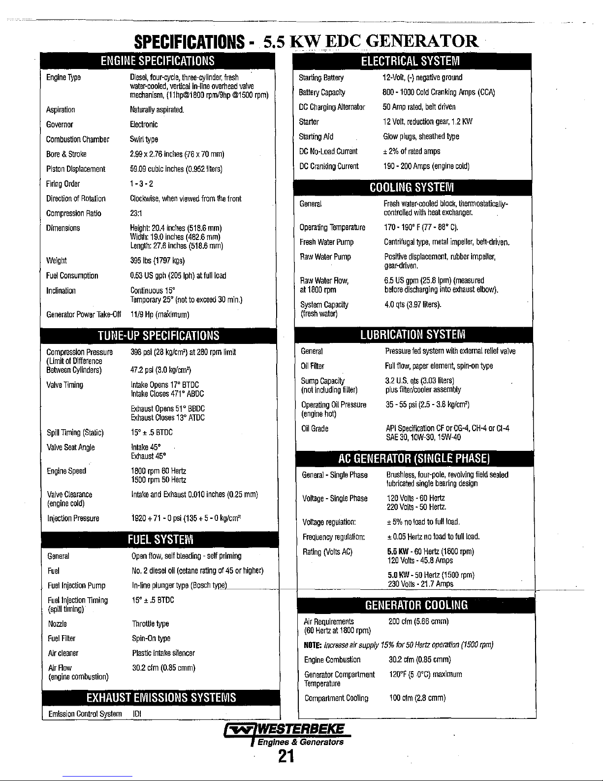
SPECIFICATIONS·
5.5 KW"EDC
GENERATOR
Engine
Type
Aspiration
Governor
Combustion
Bore & Stroke
Piston
Firing
Direction
Compression
Dimensions
Weight
Fuel
Inclination
Generator
Compression
(Limit
Between
Valve
Spill
Valve
Engine
Valve
(engine
Injection
General
Fuel
Fuel
Fuel
(spill
Nozzle
Fuel
Air
Air
(engine
Chamber
Displacement
Order
01
Rotation
Ratio
Consumption
Power
Pressure
of
Difference
Cylinders)
Timing
Timing
(Static)
Seat
Angle
Speed
Clearance
cold)
Pressure
Injection
Pump
Injection
Timing
timing)
Riter
cleaner
Flow
combustion)
ENGINE
Take"Off
SPECIFICATIONS
Diesel,
water-cooled,
mechanism,
Naturally
Electronic
Swirl
2.99 x 2.76
59.09
1 - 3 -2
Clockwise,
23:1
Height:
Width:
Length:
3951bs
0.53
Continuous
Temporary
11/9
TUNE-UP
396
47.2
Intake
Intake
Exhaust
Exhaust
15'
Intake
Exhaust
1600
1500
Intake
1920 + 71
FUEL
Open
No.2
In-line
15'
Throttle
Spin-On
Plastic
30.2
four-cycle,
type
cubic
20.4
19.0
US
three-cylinder,
vertical
in-line
(llhp@1600rpml9hp@1500rpm)
aspirated.
inches
(76 x 70
inches
(0.952
when
viewed
inches
(516.6
inches
inches
kgs)
(205
Iph)
(462.6
(516.6
27.6
(1797
gph
from
at
full
mm)
liters)
mm)
mm)
mm)
Iresh
overhead
the
front
load
15'
25'
(not
to
exceed
30
min.)
Hp
(maXimum)
SPECIFICATIONS
psi
(26
kg/cm')
at
260
rpm
limit
psi
(3.0
kg/cm')
Opens
no
471'
Opens
Closes
BTDC
0
0
45
60
Hertz
50
Hertz
Exhaust
-0
51'
13'
psi
BTDC
ABDC
BBDC
ATDC
0.010
(135
inches
+ 5 -0
(0.25
kg/cm'
Closes
±.5
45
rpm
rpm
and
SYSTEM
flow,
sell
diesel
plunger
±.5
type
intake
cfm
all
BTDC
type
silencer
(0.65
bleeding _ self
(cetane
type
cmm)
priming
rating
0145
(Bo'3ChtyIllL
valve
mm)
or
higher)
____
ELECTRICAL
Starting
Battery
DC
Charging
Starter
Starting
DC
No-Load
DC
Cranking
Battery
Capacity
Altemator
Aid
Current
Current
12-Volt,
600
50
12
Glow
±
2%
190 -200
COOLING
General
Operating
Fresh
Water
Raw
Water
Raw
Water
at
1600
rpm
System
Capacity
(Iresh
water)
Temperature
Pump
Pump
Flow,
Fresh
controlled
170
Centrilugal
Positive
gear-driven.
6.5
before
4.0
LUBRICATION
General
Oil
Filter
Sump
Capacity
(not
including
Iilter)
Operating
(engine
Oil
Oil
Pressure
hot)
Grade
AC
General -Single
Voltage -Single
Voltage
regulation:
Frequency
Rating
regulation:
(Volts
AC)
GENERATOR
Phase
Phase
-+-------~2~311l.0'!:VO~lt~s
Pressure
Full
3.2
plus
35 -55
API
SAE
Brushless,
lubricated
120
220
±
±
5.5
120
5.0
GENERATOR
supply
200
15%
30.2
120°F
100
Air
Requirements
(60
Hertz
at
1600
NOTE:
increase
Engine
Combustion
Generator
Temperature
Compartment
Compartment
rpm)
air
COOling
SYSTEM
(-)
negative
ground
-1000
Cold
CranWng
Amps
(CCA)
Amp
rated,
belt
driven
Volt,
reduction
gear,
1.2
KW
plugs,
sheathed
twe
of
rated
amps
Amps
(engine
cold)
SYSTEM
water-cooled
-190' F
displacement,
US
gpm
discharging
qts
(3.97
with
heat
(77 -66'
type,
metal
(25.6Ipm)
liters).
block,
thermostatically-
exchanger.
C).
impeller,
rubber
(measured
into
exhaust
belt-driven.
impeller,
elbow).
SYSTEM
fed
system
with
external
relief
Ilow,
paper
element,
spin-on
type
U.S.
qts
(3.03
filter/cooler
SpecITication
30,
Volts -60
Volts -50
5%
no
0.05
Hertz
KW·
Volts -45.6
KW -50
liters)
assembly
psi
(2.5 -3.6
kg/cm')
CF
or
CG-4,
CH-4
10W-30,
15W-40
(SINGLE
four-pole,
single
load
no
60
Hertz
Hertz
.::2!112.7~~
bearing
Hertz
Hertz.
to
lull
load
Amps
PHASE)
revolving
design
load.
to
luilioad.
(1600
(1500
_______
or
lield
rpm)
rpm)
GODLING
cfm
(5.66
cmm)
for
50
Hertz
operation
(1500
rpm)
cfm
(0.65
cmm)
(5
.O°C)
maximum
cfm
(2.6
cmm)
valve
CI-4
sealed
1-----'---
Engines
21
& Generators
Page 30
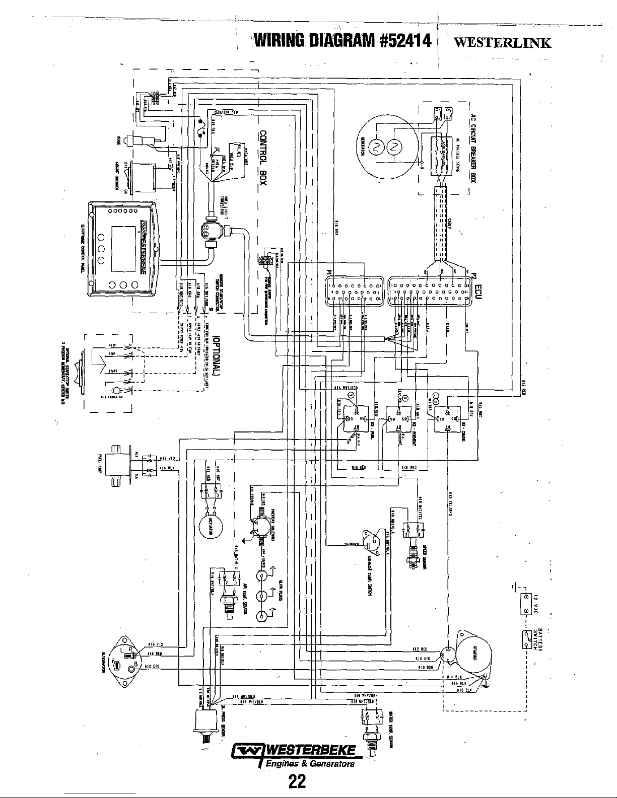
~-----
_______
L
__
=,
00
I~
I
I
I
crt
l:
:::pJ
I
q
rt.
i .
000000
0
I
0
I
0
[JI
i
000
I
-
- -
r - - 1 I
I
- -
~'
~_':;
~
~::
."
..
1"""
.
________
________
I 1
I I
__ : __________
____________
..J
Q
~IU.
III
I,
•
~
•
~
0
1'.
"
~
~'5
~"
;;
gi!!
..
-
I~
~
'-
~
.-"
~I
I~:~
I;
.,
:::
I::
Iii
':
Ii
:;:.
:13
,g
1::2
I~»
.J
:;
J~
g
~
-
_
a
~
i5
c
~
;;;; I
f·~·
1-
t
I;
11;
Iii
I~ I~
I::
:!
I:
J;
:i
J
WIRING
I
12
z
DIAGRAM
I~
l!!l
IX
I
I
•
•
'----
:!!
'
0000600'
.o-?-
: ii
~
,
I •
~
I
Ii
J i
I
~
#524141··
I
~
I~cf)
/1
L
0011
'000·0·060
"
ooooocO"
00'
0
0
000
~
WESTERL~~--~-~--~
I
~J
ti+~
'"
"
'"
III"
'"
II
II''"'
'"
'"
'"
'"
'~,
,(
~ ! ~
00
,
>
I~
,
Ig
,
;
,
~
II
"
•
III
J
,,~
~
obo_~1
Pl
.C:
00
,
wm
~
e
.
~
(L
£3
,
~
,
~~g~~
b~'
,:
ii
! •
;~
•
I
-
•
'
""~
I -I
,
P(l)
0
L R
0
B)
lo:;;..J
116VID
IIiKE
110
:C
i
;
"""
mGlK
DHD
,-
I
dJ
;:
;
, .
,
,
-
"
t
~
t'-
~
s
" I
~
"I-'~'
,
~r!
!
tt'-D.
•
>=p
~
• I
, -
~
~
,
e
;:
II
!!
1I1HIBL
III
~~T
i
.
,
cl)J
cpJ;
~
cb-r
lUcK
...
i t
e . _
.--:
' r.,-,WESTERBEKE , I
7 Engines & Generators .
!liKEO
~
....
~
. i
!i
~
mrKTIGRK
IlltiHlIULK
~i
rl=
~
Hi
RED
•
:--
,
~
i t
~
~~;
II!
Rto
110
RED
ItODRG~j~6~
!i
~
1\66l!
•
I
116
6l~
)B
:"i6lK~
,
,
,
,----------------
I -
'11-
,
,
~~
,
22
Page 31

WIRING
l'.S.
III
-.
II
~
I I
DIAGRAM # 52793
.
, ,
NMEA 2000
!
~lc'i'
,
.",
I~
.,.'"
L
.-=
~
I1I1'i=I
.= . If=: ...
=f=lll:~
~Ih'
y' y'
~:~
~/
t-'
It:
':·
y
IL--I-+-l---I--+-l-
,li~
~I'i
~
~:
81~-
~';
I
_____
f-'
'-
;j
I
I
;
.J
n,
.:~
I .
Engines & GefJerators
22A
Page 32
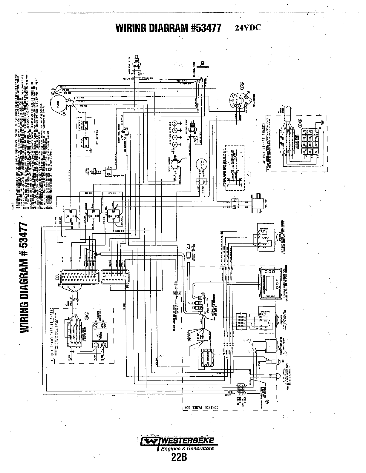
t-l
""
~"
WIRING
!;
, ,
DIAGRAM
I',
#53477
24VDC
-
-----=
·
..
WWESTERBEkE
Engines & Genera'tors
22B
Page 33

NOTE:
ments
be
below
is provivedto
ENGINE
WESTERBEKE
peiformed
by a competent
assist
ADJUSTMENTS
recommends
the
that
engine
mechanic.
the
following
mechanic.
The
engine
information
adjust-
DRIVE
For
equipped
front
guard
advis~d
required.
Excessive
and
A
slipping,
The
deflected
inch
midpoint
belt.
Adjusting
1.
2.
3.
4.
5.
6.
7.
8.
BELT
your
safety,
with belt
of
the
engine.
is
NOTinstalled
that proper
drive belt
reduce
the service
slack
belt
resulting
drive
belt
no
(12mm)
between the
A spare belt or
A
WARNING:
drive
belt's
Remove
Loosen
loosen
With
edges.
Pivot the idler
loosen
Replace the
minutes
Remove
the
the
the belt
or
Tighten
and
Replace the
or
less
Belt
the belt
tighten.
the pivot
the
ADJUSTMENT
WES1ERBEKE
gnards
that
cover
("Out of sight -
for
that
purpose.)
inspection,
the
presence
in
is
properly
than
as
the belt
belts
Never
tension
tension
life
high
3/8
two
while
can
of
the
of
oil
operating
adjusted
inch
(lOmm)
is
depressed
pulleys
should
attempt
the
service,
cause
engine
Tension
guard.
pivot
belt that
adjusting
loose,
sheave
gnard.
then
shut
gnard
guard.
holds
bolt.
inspect for
to
the left
bolt
and
the
Operate
and
the
the
generator
recheck the belt tension.
generator
over
out
of
and
rapid
fresh
water
on
the
temperatures.
if
the
and
with
on
the
always
be
to
check
is
the
idler
wear,
cracks
or
right
adjusting
generator
down.
models
the
belles)
mind."
Operators
maintenance
wear of
pump's
belt
can
belt
can
no
more
the
thumb
longest
span
carried
or
adjust
in
operation.
sheave
and
as
required,
bolt.
for about 5
come
on
The
are
the
bearing.
cause
be
than
at
on
and
frayed
the
belt
is
belt
belt
1/2
the
of
the
board.
the
to
TORQUING
After
every
re-torqued.
Tighten
shown.
Before
1/4
to
procedure
illustration
Bolts #1, 2 and 3, (l2mm socket)
Bolts #4,
RocketshaftHold Down Bolts Rocker
FUEL
In
case
injectors
injection
loss
of
in
injector
clean
injector
Before
base of
falling
out
easily
the injector side-to-side
free
it,
The injector
washer.
replaced
installed.
NOTE:
additiolUll
THE
CYLINDER
the
initial
break-in
500
hours
thereafter,
the
cylinder
Make
applying
1/2
of a turn and
according
to
5,
6, 7,
Cover
head
sure
the
the
specified
to
the
right.
8,
9,10
Hold Down
CYLINDER
INJECTORS
of
severe
vibrations
checked
service
positive
room
as
removing
the
down
and
TIris
with a new
Refer
and
center.
fuel pressure
faults.
Since
enviromnent,
a spare
should a problem
the
injector
and
then
START
1988 ± 142PSI
to
into the injector
is
held
lift it
seats
in
washer
TO
INJECTION
to
the
~l
infol7nation
HEAD
period
(approximately
the
cylinder
bolts
according
engine
is
cold
torque
then
apply
the
numbered
and
11
Cap
HEAD
BOLT
and
overnauled
Poor
fuel
to
the
fuel
injectors
it
is
best
old
injector,
help
prevent
hole.
in by
carbon
with
the
out
the
cylinder
should
be
removed
washer
when
.
PRESSURE
(140 ± 10KG/CM')
injector
.
page
BOLTS
50
hours) and
head bolts should be
to
the sequence
when
this
is
done.
to
the bolt,
the
torque
sequence
14
- 22 ft-lb
(14mm
12mm
Nuts
- (lOmm socket) (snug)
PATTERN
detonation
by
an
authorized
quality,
injection
must be
to
carry
occur.
clean
the
any
rust or
If
the injector
build-up or
aid
of the
head
on a copper
the
new
in
this
loosen
..
Follow
shown
socket) (54 -
socket
(11 -16
noise,
have the
fuel
contaminant's
pump
can
serviced
at
least
One
area
around
debris
will
the
like,
socket
wrench
with
the
injector
injector
nwnual
it
this
in the
61
and
result
in a
extra
the
from
not lift
work
sealing
is
for
ft-Ib) .
ft-lb)
to
and
....
WESTERBEKE
Engines & Generators
23
Page 34

ENGINE
ADJUSTMENTS
GENERATOR
Once
the
there
may
during
this
period. A no-load
required
These
are
mal
break-in
Frequency
indicated
When
the
ontput frequency
FREQUENCY
diesel
generator
be
adjustments
the
engine's
in
conjunction
not
warrantable
and
maintenance.
is
a direct
by
the
following:
generator is
is
break-in
result
60
When the generator is
outpnt freqnency
Therefore
speed
perform
1.
must
With
the
to
the
the
AC
connections
change
These
connections
tion
of
this
A
WARNING:
cettain
away
from
is
change
be
changed.
following:
engine
terminal
diagram
the
Hertz
manual.
that
everyone
pulleys
50
the
stopped,
block
circuit
ADJUSTMENT
set
has
required
period
voltage
adjustment
with
the
adjustments
of
engineigenerat<;>r
rnn
at
1800
Herlz.
rnn
at
1500
Hem.
generator's
To
accomplish
.
connect
in
accordance
specified
connection
are
shown
.
Before
statting
is
clear
and
belts
(HERTZ)
been
placed in
for
engine speed
(first 50 hours) or after
engine's speed
as
rpm, the
rpm, the
frequency,
the
the
AC
with
for
your generator
to
in
the
GENERATOR
the
of
moving
during
may
also
adjustment.
they
relate
speed,
AC
AC
the
frequency
output
the
the
capacitor.
engine
parts!
test
procedures.
operation,
AC
make
(Hertz)
be
to
nor-
as
voltage
voltage
engine
change,
leads
voltage
set,
sec-
Keep
to
and
ELECTRONIC
The
Electronic
sensing
flywheel.
the
engiries
controller
engine
to
GOVERNOR
Governor
the engine's
The
governor's
speed
and
signals
the
the
desired
Actuator
The
following instructions
the actuator.
1.
Shut-off
2.
Disconnect
3.
Measure
mounting
the
DC
the
acI\I'lIOr
the distance between the actuator and
smface as
regclates
RPM
with a magnetic
controller
if there is
actuator
speed
electronically.
are
power
to
wires
shown.
the
engirie
continuously
any
discrepancy,
and
the
actuator
for adjusting
the
generator.
fuim
the
sPeed
pick-up
wiring
at
monitors
the
adjusts
ENGINE
SURFACE
or
replacing
harness.
the
by
the
the
MOUNTING
engine
2.
In
Electronic Control Unit
engine
and OFF for
for
3.
Star!
and
out put
as
WHEN
CHANGING
.
FREQUENCY
ON
THE
CONTROL
BOARD
MUST
ON
FOR
50
HZ
the
control box on
the
speed/generator
60
Hz.
Select the correct switch position
the
desired operating hertz.
the engine and
no
load
AC
as
needed using
observe
voltage output. Adjust no load
needed to increase or
THE
(50/60
GENERATORS
HZ)
PANEL
BE
SWITCHED:
AND
OFF
SWITCH
ECU
FOR
flO
HZ.
#1
generator is located the
(ECU).
frequency.
Switch # I
ON
for
contoIs
50
generator hertz
the
capacitor taps
decease
no load
SWITCHES
#7,
AC
Hz
AC
#8
or
voltage.
#9
4.
Back-offthe 1
5.
Apply a
actuator
mounting
actuator
measured
(The
standard
6.
Reconnect
NOTE:
Should
the
proper shut
NOTE:
For
Troubleshooting, refer
diesel
ACTUATOR
REFERENCE
7/16"
small
amount
and
screw
boss.
Maintain
and
the
engine
Secure
distance
the
actuator
the
unit
jam
nut
and
down.
additional
generators.
jam
nut
and
of
teflon
the
actuator into
the
same
mounting surface
the
actuator's position
is
13/16"
wires
and test
fail
to
shut
the
to
down
actuator
the
booklet
thread
information.on
ENGINE
'SURFACE
unscrew
sealant
the
distance
to
7/8").
1+---13/16"
and
only
in
LA
Electronic
on
MOUNTING
theaclllator.
to
the
engine's
between
as
with
the
unit
go
to
to
Y2
tum
Governing
our
website
replacement
the
previously
the
jam
nut
TO
idle,
to
7/8"
Loosen
obtain
for
STANDARD
Ehglnes & Generators
.
24
Page 35

VALVE
NOTE:
engine's
BOLTS.
Pull
off
rocker
Remove
the
cylinder
Valves·are
adjusted
stroke.
order
Valve
crankshaft
cylinder
piston
the
look
now
in
Align
timing
the
by
and
should
CLEARANCE
Retorque
valves.
A
WARNING:
engine
is
cold.
ing
order
of
the
to
the
specified
off
the
air breather
the
rocker
cover
shaft
and
the
glow
crankshaft
(1-3-2
adjustment beginning with cylinder
cylinder).
for
starting
the
cylinder
the
#1
rotating
after
to
for
valve
adjusted with
at
Top
Dead.
Each
cylinder
for
slowly
#1.
Watch
is
on
it's intake stroke
Continue to rotate the crankshaft slowly and
the
intake
it's compression stroke (the
towards
IDC
mark
marker
on
Piston
at
TOC
the crankshaft approximately
this point
not
move.
ADJUSTMENT
the
cylinder
See
TORQUING
Adjust
Valves
engine.
torque
bolts
valve
plugs
be easily rotated
adjustment.
WESTERBEKE three cylinder engines).
and observe the operation of the
for the intake valve to
valve
the front gear case cover
and
head
the
are
adjusted
Tighten
before
pipe
from
and
assembly.
from
each
the
cylinder
Center (IDC)
is
adjusted
(the
to
close.
IDC)
..
on
the crankshaft front pulley
of
it's compression stroke. Confirm
the
two
bolts
before
adjusting
THE
CYLINDER
valve
clearance
by
the
cylinder
adjusting
the
rocker
the rocker
of
the cylinders to enable
by
hand to position each
in
of
its
following the engine's
piston
TIrls
indicates the piston
valves for the
when
cylinder
head
tlie
valves.
cover
cover
to
the
piston
compression
#1.
open
indicating the
is
moving
piston
is
when
20
degrees before
#1
the
HEAD
the
in
the
fir·
bolts
and
take
expose
the
being
firing
Rotate
the
valves
for
down
in
moving
with
the
positioning
this
cylinder
is
up
Re-install
threads)
bolts.
manual.
ENGINE
Check the
remove
shut-off
the
tester
motor
this
matically
of the
more
Siandard
If
is
for
cylinder
cylinder
comes
Abnormally
carbon
accompanied
NOTE:
cause
TORS.
fuel
the
glow
and
assemble
See
TIGHTENING
COMPRESSION
compression
all
fuel
injectors,
solenoid
injector
a weak
either
the
hole
or
on
the
adapter
untl1
the
pressure
process
for
each
(at
least
others.
Compression
than
35.5
psi
compression
cylinder
valve
or
piston
weak
cylinder,
is
still
low,
to
seal
the
up • the
In
may
pressure
rings
high
accumulations, a condition
by
high
crue
of
severe
be
fuel
Poor
fuel
to
tJze
faults.
When
re-inslalling
plugs
(use
the
rocker
TORQUE
pressure.
or
glow
wire,
and
install a compression
glow
plug
and
crank
reaches a maximum
cylinder.
20%)
lower
pressure
(2.5
kglcm')
pressure
is
rings
readings
398
flanked
by
related.
adjust
as
apply a small
and repeat
are
faulty.
on
pressures
vibrations
injector
quality,
the
contaminates
injection
glow
problems,
pump
plugs
anti-seize
hole.
the
Look
compression
at
Ib/ln'
healthy
Check
needed
all
and
compound
cover
and
SCHEDULE
To
do
this
plugs,
disconnect
Connect
engine
for
cylinders
should
280
rpm.
al280
cylinder,
the
and
amount
the
test.
cylinders
that might be
noise.
and
detonation
see
and
will
result
use
anti-seize
on
the
rocker cover
in
this
warm
the
engine,
the
fuel
adapter
a compression
with the starter
value.
Repeat
with
dra-
than
the
average
not differ
rpm
'(28.0
valve clearances
test
of
011
If
indicates
by
kg/em')
the
problem
again.
If
into
the
compression
heavy
noise,
FUEL
INJEC-
loss
of
positive
in
injector
compound.
in
the
the
Adjust
the
valves
in
#1
cylinder for both intake and exhaust
Proceed
Rotate
rotation
order.
the
Acljust
(0.25mm)
stem.
to
the next cylinder
the
crankshaft 240 degrees in the normal direction of
and
adjust the next cylinder's
Rotate the crankshaft another 240 degrees
valves
of
the
next cylinder in the
each valve's clearance
feeler gauge between the rocker arm
Make
sure
to
adjust all valves while the engine
in
the firing
by
insertIng a
VALVE
valves
firing
CLEARANCE
0.25
mm
COLD
order.
in
the firing
order.
O.OlOin
and
(0.010
In)
ENGiNE
and
adjust
the
valve
is
cold.
Engines
25
COMPRESSION
ADAPTER~
.t~f
~--
& Generators
TESTER
.>.
'~:~n;'
.:,'
___
INJECTOR
GLOW
OR
PLUG
HOLE
Page 36

NDTE:
WESTERBEKE
ments
be
below
is
ENGINE
performed
provided
by a competent
to
assist
ADJUSTMENTS
recommends
ihe
that
engine
mechanic.
the
following
mechanic.
engine
The
-----,====--=---=--=-=--,,-----------
adjust-
information
Injection
If
your engine's fuel injection timing
the engine will uot operate properly,
start Have the injection pump delivery rate checked by a
well-established fuel injection shop.
-follows:
NDTE:
fuel
do
this,
side
move
fully
1. Remove the high pressure fuel line
No.1 injector and the No.1 fuel
2. Remove the No.1 fuel delivery
"0"
the
3. Reinstall ouly the delivery valve holder and reattach the
high pressure fuel line to the delivery
that the end that would connect to
pointing away from the engine fuel
line during the timing check.
Rotate the engine's crankshaft in its
rotation'to position piston
,compression stroke.
Move the throttle lever
the electric
(as viewed from the front), catching the
fuel line, until the instant the fuel completely stops
(no drips). At this instant, the 15°
crankshaft pulley should be directly
indicator
If
the specified injection timing
attained, adjust the timing by increasing or decreasing the
thickness
mounting
Changing the shim thickness by 0.004
changes the injection timing
To
advance the timing, decrease the
required,
required; Refer
numbers,
Pump
Timing
The
injection
delivery
unscrew
cover
to
the
fuel
to
the
left)
ring and remove the delivery
holder.
lift
on
of
flange
To
pump
fuel
position
expose
the front of the gear
shim material under the injection pump's
retard the timing, increase
when
performing
the
fuel
shut
the
injection
rack
to
the
full fuel
secure
it
in
this
No.1
to
its full
pump.
Slowly rotate the cnmkshafr clockwise
to
change the injection timing point.
to
your Generator's
Adjustment
rack
off
solenoid
pump
delivery
position
at
open
BIDC
case ± .5
(15°
by
approximately one degree.
(Spill
is
not
properly adjusted,
and
may
be difficult
Adjust
the injection
needs
to
be
in
this
spill
timing.
and
remOve
fuel
rack.
position
thenproceed.
from
between the
delivery
valve
normal
the
aligned
shim
Parts
valve
holder over
valve
spring beneath
holder.
Attach it
the
fuel
injector
will
flow
from
direction of
beginning
position and operate
fuel
from the
timing mark
with the timing
degrees.
BIDC) cannot be
inch
(O,Olrnm)
thickness, as
the
shim thickness,
List for shim part
Timing)
the
full
the
Manually
(move
holder.
is
this
of
its
No,
flowing
on
as
To
to
so
1
the
as
INJECTION
UNION
STOP
BRACKET
CONTROL
SLEEVE
CONTROL
IT
MARK
ON
PULLEY
RACk
PUMP"
WIRE--..J
RACK,
DELiVERY
PLUNGER
VALVE
ROLLER
HOLDER
SPRING
.vALVE
Engines & Generators
26
TIMING
TIMING
POINTER
CRANKSHAFT
PULLEY
MARKS
Page 37

'~--------""'---
ENGINE
NOTE:
WESTERBEKE
ments
be
performed by a competent
below
is
provided
OIL
PRESSURE
The engine's oil pressure,
control
pane\.
The red light
will shutdown
restart the generator without checking
problem.
NOTE:
A
reading
pressure
depending
placed
LOW
OIL
The
specified
(0.3 -
0.1
engine
worn
bearings.
Fe)tdings,
TESTING
To
test oil pressure, remove the oil gallery "T" plug
install a mechanical oil pressure gauge in its place. After
wanning
'Oil
PRE$SU~€··
if
the oil pressure
newly
started, cold
upwards
reading
on
upon
the
generator.
of
as
the
PRESSURE
safe minimum oil
kg/em'). An oil pressure of 5
down.
A gniduallossof
For additional iufonnation
see
the
ENGINE
OIL
PRESSURE
up
theeirgine, read
is
constantly monitored
will
illuminate and the generator
falls
engine
60 psi. A warmed
low
as 35
psi.
te"1perature
35.0
IbM
9·1.3
!t.\b
of
pressure
oil
TROUBLESHOOTING
.the
oil pressure gauge.
(3.8
kg/em')
(1.2
-1.8
below 5 psi.
the
can
have
engine
These
the
engine
is
psi
pressure usually
or
m·kg)
oil and
an
can
readings
and
4.3 -1.4
Will
shut the
on
low
more
to
assist
by
Do not
finding
oil
pressure
have
will
the
psi
indicates
oil
chart.
at
1800
,the
pressure
and
ADJUSTMENTS
recommends
the
the
an
oil
vary
load
.'.
rpm
that
the
following engine
engine
mechanic.
mechanic.
~
-GLOW
.
PLUGS
To
inspect the
connections, then unscrew or unc\amp each plug from the
cylinder
with a soft
carbon
for
wear
the
plug.
An accurate
Touch
other
to
plug
will
used
with
multimeter
A
hot
to
when
plug,
head.
Thoroughly clean each plug's tip and thre""s
brush and cleaning solution to remove all the
and
oil deposits. While cleaning, examine the tip
and'burn
way
one
prod to the glo\" plug's wire connection, and the
the body
have a 0.4 -
the plug in or out of theengine.You can also use a
to test the power drain
WARNING:
the
touch.
testing
adjust-
The
information _
remove the electrical tenninal
er.osion;
to
of
the
if
it has eroded
test
glow
plugs
is
with
the
glow
plug,
as
shown.
0.6
ohm resistance. This method can
(5
- 6
amps
,
These
glow
plugs
will
Be
careful
not
toburD
plug.
.
TESTING A GLOW
, \
WITH
AN
OHMM,ETER
PLUG
too
much, replace
an
ohmmeter.
A good glow
per plug).
become
your
very
fingers
be
TERMiNAL
ENO
MANUAL
Shou\dfue stop button
function to stop the engine; the
manual shutdown leverloc.led
above
until
ENGINE
the side
the
engines comes
SHUT-OFF
~n:'the
~ontrol
oil;
fill.
Siffiply hold dowritlie 'lever
toa
colllplete
TESTING
engme
on
the engine blockjust
OIL
PRESSURE
p.u:elfail inits
is
equipped
sidp.-
n()rn:,al
with
to
fueleft '
'
,
TIP
a
\TESTING
•
USING
GLOW
PLUG
7 -11
Fr-LB
iA:GhOW
;"LUG
,AlrEST,UIGHl
TIGHTENING
(1.0
,TORQUE
-I.S'M,KG)
+
Re-install·the plugs
plugs
should get very'hot' (at thetenniilal
seconds.
circuit. When reinstalling the
compound
If
the plugs don't heat up quickly, check for a short
on
the
in,th_e
threads.
engineand
glow
plugs,
t~st
them
end)
use
again.
The
Within 7 to
anti-seize
15
SIDE
Oil
FILL
Engines & Generators
27
Page 38

FUEL
INJECTORS
REMOVING
NOTE:
1.
Disconnect
loosen
and
bending
2.
Using a 17mm
its
lose
the
NOTE:
prior
any
hole.
by
side
it
and
3. The
jng
injector
tor
INJECTION
1.
Using
tion
limit,
tester,
A
of
skin
enters
a.
If
replace
h.
Set
dust
c. Mount
tester.
d.
Use
of
e.
Operate
bleed
lever
ing
THE
Injector
must
the
the
lines at
move
them
the
lines.
entirety
carbon
is
from
the
two
fuel
return
Clean
to
lifting
rust
or
If
the
injector
build
with
the
then
lift it
injector
washer.
and
reinstalled.
debris
This
replaced
TESTING
the
nozzle
starting
pressure
adjust
or
take
the
CAUTION:
snch
velocity
of
fingers
the
bloodstream,
the
diesel
it.
At the
the
nozzle
or
dirt.
the
the
fuel
68'
F (20'
the hand
the
air
at
intervals of
the
injectipn
INJECTORS
be
serviced
high
out of
long
the
sealing
line
the
area
it
out
from
up
aid
of
out.
seats
in
washer
tester,
replace
following
The
that
and
fuel
of
tester
nozzle
at
the
C)
in
the
starting
in a "clean
pressure
their
attachment
the
way
socket,
top
of
the
washers
to
each
injector.
around
of
the
cylinder
falling
will
not
or
the
like,
the
J7mm
the
cylinder
should
with a new
check
of
nozzle
the
nozzle.
precautions:
spray
it
may
hands,
it
the
nozzle
same
time,
in a clean
and
nozzle
approximate
lever
of
nozzle
one
stroke per.second
pressure.
lines
from
to
of
the
remove
lift out
injected
destroying
may
nozzle
line,
the
injectors.
and
banjo
the
base
head
down
into
easily
work
the
deep
socket
head
be
removed
washer
the
spray
and,
if it
When
from
ppnetrate
cause
tester
clean
or
place
holder
temperature
tester
then
room"
erwironment.
the
il\iectors
the
injection
injectors.
fuel
return
Take
care
bolt
that
of
the
injector
to
help
the
injector
and
is
injector
wrench
on a copper
with
when
pattern
exceeds
using
the
nozzle
deeply
into
tissue.
If
blood
poisoning.
is
discolored,
replace
where
there
on
the
nozzle
several
move
the
while
and
pump
Avoid
line
not
attaches
prevent
held
in
side
to
to
free
seal·
the
the
injec-
and injec-
the
nozzle
is
the
it
the
filter.
is
no
times
hand
read-
to
to
in
Inspecting
1.
Operate
one
rectly
injects
strips.
defect.
ging
cleaned
expose
and
2.
Apply
by
nozzle
on
repl~ced;
remain
indicate a
the.
stroke
in
its
fuel
Also, a spray
These
with
before
ones
cause
the
operating
tip.
the
bottom,
A
on
il
The
injection starting
increasing
The
(0.05
With
increased
replacing the
remove
the specified
or
shim
has
mm):
each
0.0020in
approxhnately
the
decre!lSing
between
shim,
body
torque:
Spray
Pattern
hand
lever
per
second
axial
direction.
in
an
oblique
defects
dust
and,
reassembly.
skin
to
infection.)
CHATTERING
pressure
If
the
defect.
10
of 1635Ib/in'
the
hand
it
drips
it
is
considered
very
small
tip
of
pressure
different
0.0049in
(0.05mm)
grip
with a wrench.
of
the
nozzle
to
check
A nozzle
direction
in
the
form
may
sometimes
therefore,
this
(Care
spray
all
as
bI
3i
'il
FAULTY
,',
¥~'
,(I
TEST
lever,
and
or
has
a large
amount
the
nozzle;
DRIP
TEST
for
the injectors
the
thickness
thicknesses
(1.25mm).to
increase,
71.1lb/in'
the
retaining
Tighten
tester
at
intervals of
if
the
fuel
is
injected cor-
is
defective
or
in
several
of
particles indicates a
be
caused
parts
should
should'
be
taken
it
may
penetrate
(115
kg/cm')
check
the
drips
accumulation
defective
of
however,
fuel
and
may
this
should
sometimes
D
is
of the
adjusting
for
every
0.0020
0.0669in
injection
(5.0
kg/cm').
nut
in a vi&e
the
ADJUSTING
SHIM
When
retaining
!
SHIM
~
i
if
it
separate
by
clog-
be
carefully
not
the skin
to
nozzle
from
·of
fuel
be
does
not
fi:'
,
..
.
,.
adjusted
shim.
in
(I.7mm)
pressure
and
nut
THICKNESS
to
the
by
is
to
INJECTION
1920
PRESSURE
PSI
Engines & Generators
28
Page 39

-
--------'
,--=----~--------~c_-~
,
.-
..
START
BUTTON
indications.
START
BUTTON
engagement.
,
START
BUTTON
indications
fuel
solenoid
Generator
start,
fuel
Note:
there
:
If
the
engine
will
tenninate
will
display
Battery
runs
Battery
not
Generator
(Fault
display
NOTE:
The
is
protected
reset
circuit
control
Engine
Exhaust
--
-Problem
depressed,
depressed,
depresssd;
OK;
starter
not
functioning.
engine
cranks,
solenoid
energized.
is
a 8 -
does
not
and a Underspeed
on
the
down.
charging
engine
stops.
under
engines
by a 20
breaker
panel.
starts,
runs
smoking
problems
solenoid
10'
sec.
start.
LCD
speed)
DC
electrical
amp
on
the
and
shuts
no
panel
no
starter
panel
but
does
crank
The
display
rocker
front
down,
_
OK
not
cycle.
cycle
fault
screen.
system
type
of
the
Note:
rocker
·.c
ENGINE
The
engines
type
reset
Probable
Batteryswitch'noion.
1.,
2.
Circuit
breaker
3.
Loose
b~ttery
Connection
1.
Faulty
SOlenoid.
2.
loose
Low
K1
relay.
Poor
Defective
Faulty
Preheat
2.
1.
High
Low
2.
3.
Poor
DC
alternator
4.
DC
1.
Alternator
2
..
1.
Switches
or
disconnected,
2.
Fuel
20
Amp
3.
(LCD
4.
Exhaust
Water
5.
6.
Air
Faulty
1.
Water
2.
Blue
1.
2.
White
3.
Black
battery
battery.
connections
fueling
solenoid
resistance
reSistance
battery
charge
starvation.
display
in
intake
oil
temperature
smoke,
smoke.
smoke.
3.
4.
5,
1.
2.
1.
TROUBLESHOOTING
DC
electrical
circuit
breaker
Cause
tripped/Off:
connections.
-to
solenoid
connections.
to
fuel
solenOid.
system.
faulty.
leak
le<;lk.
connections.
not
charging.
circuit
faulty.
drive.
andlor
wiring
circuit
breaker
blank)
system
is
fuel.
obstruction.
pressure
system
mounted
-
'faulty.
fuel
solenoid.
to
ground.
loose
tripping.
restricted.
switch.
switch.
l"'fN"IWESTERBEKE
I Engines & Generators
is
protected
on
the
1.
2.
4.
1.
2,
3.
4.
5.
1.
2.
1.
1a.
1b.
'
1c.
1d,
2.
1,
2.
3.
4.
1,
2.
are
1.
2,
3.
4.
5,
6.
1.
2.
1.
1a.
by a 20
control
panel,
-,
,--,-. -
Check
switch
Reset
breaker;
circuit
and,
check
check
(+),connection
engine
ground
Check
connection.
Check
that
12
Check
battery
Check
battery
Check
K1
relay.
Check
connections.
Check
that
fuel
Check
Switch
Replace
Check
Change
Check
Check
lines.
after
Cbeck
Check
corrosion.
Check
DC
Penorm
DC
Check
for
present
Inspect
Inspect
Check
Check
Ensure
cause
Check
2.
2a.
3.
3a.
3b.lmproperly
3c.
12
run
solenoid.
thalfuel
to
combine
batteries.
fuel
lift
Inlet
solenoid.
wiring.
Do
not
short
is
all
wires
table
connections,
ELECTRICAL
D.C.
ELECTRICAL
drive
loose
connections.
at
the
wiring
switches
fuel
for
high
breaker
tripping.
for
blockage
Pump
water
bleed
fuel
Check
air
intake
Check
oil
pressure
Check
water
Incorrect
grade
Crankcase
through
the
Engine
Is
running
Faulty
Injector
Improper
Fuel.burn
insufficient
.exhaust
system;
lack
of
air -check
v6lltilation,
amp
Verilicalion}Remedy
--
andlor
if
breaker
circuit
stud.
volts
connections.
charge
voltsare
valves
pump.
fuel
filter.
Insert
start
located.
for
connections
voltage
belt
tension.
Exc.
for
supply,
DC
is
from
system.
temperature
is
ovenilled
exhaust).
or
grade
Incomplete
air
for
timed
_.
battery
connections.
trips
again,
for
to
starter
Check
are
present
state.
pressnt
areopen.
house
sensitive
engine.
temperature
at
check
check
sho.rts
to
ground.
solenoid
battery
cable
at
the
solenoid
at
the
(+)
and
start
batteries.
(0 -.25
rise
battery
tension.
amp)
connections
to
locate
for
loose
R~m.ove
belt
test
SYSTEM/ALTERNATOR.
check
of
generator
SYSTEM/ALTERNATOR.!n
Check
terminal.
short
circuits
for
proper
fuel
valves,
amperage
not
overly
or
collapsed
fuel
tank(s);
filter
cartridge.
switch.
of
engine
with
cold.
incorrect
of
fuel
or
due
proper
check
air
injectors
air
intake
Alternator
should
output
voltmeter.
and
loose
operation.
fuel
teed
draw
during
sensitive
muffler.
change
switch.
oil.
engine
oil
injector
timing.
possible
generator
to
high
back
combustion
intake).
or
valves
and
air
to
or
filter.
LCD
DISPLAY
preheat
solenoid
and
(-)
connection
connections.
connection,
connection
meter
in
and
the
fault.
connections,
alternator.
charging
circuit.
this
manual.
turn
freely.
Ensure
connections.
strainer.
operation.
heat
which
filters
and
(oil
is
blowing
overload.
pressure
in
(Check
poor
exhaust
for
restrictions
compreSSion.
Check
for
(continued)
to
on
the
battery
replace
See
See
Check
12
volts
would
out
proper
FAULTS
or
in
'"'
1,1
29
Page 40

ENGINE
TROUBLESHOOTING
LCD
·DlSPLAY
FAULTS
PROBLEM
LCD
DISPLAY
NOT
ILLUMINATE
LOW
OIL
PRESSURE
HIGH
COOLANT
HIGH
EXHAUST
BAmRY
GENERATOR
Overspeed
Underspeed
LED
TURN
WAITING
VOLTAGE
FREQUENCY
(steady
(flashing
DISPLAY
PINK
FOR
DOES
TEMPERATURE
TEMPERATURE
LED)
LED)
EDGES
ECU
PROBABLE
1.
Check
2.
20
amp
3.
Loose
4. 1 amp
1.
Oil
level
2.
Lack
of
3.
Ground
4.
Faulty
5.
Faulty
1.
Check
2.
Sea
water
3.
Check
4.
Faulty
5.
Ground
6.
Faulty
1.
Check
2.
Faulty
3.
Ground
4.
Faulty
5.
Sea
water
6.
Faulty
1.
Check
2.
Check
3.
Check
4.'
Faulty
1.
Check
2.
Check
3.
Amperage
4.
Crank
(underspeed
1.
Compartment
too
high.
1.
ECU
2.
Loose
3.
Panel
4.
Blown 8 amp
5.
Terminating
6.
Battery
CAUSE
battery.
breaker
off.
display
connection.
fuse
blown
(faulty).
low/oil
leak
oil
pressure
connection.
control
module
oil
pressure
system
coolant
pump.
water
pump
temperatiJre
connection.
control
module
sea
water
flow.
exhaust
temperature
Connection.
control
module
pump.
fire
suppression
alternator
charge
battery
control
engine
fuel
cycle
and
cable
DC
voltage.
connections.
module
speed.
supply.
load.
with
fault)
ambient
LCD
display
connection.
breaker
fuse.
Resistors.
Voltage
drive
no
to
..
(ECU).
sensor.
level.
drive
belt.
sensor.
(ECU).
(ECU).
system.
belt.
(ECU).
start.
temperature
not
OFF.
ECU.
.
switch.
compatible
VERIFICATION/REMEDY
1.
Battery
on.
2.
Turn
breaker
3.
Check
all
cable
4.
Check/replace.
1.
Check
oil
level,
2.
Test
oil
pressure.
oil
filter,
inspect
3.
Check
ground
4.
Inspect
all
the
5.
Check
sensor/replace.
1.
Add
coolant.
2.
Inspect
impeller/pump/replace.
3.
Adjust
belt
tension,
4.
Check
sensor/replace.
'5.
Check
ground
.
6.
Check
plug
1.
Inspect
thru
as
needed.
2.
Test/replace.
3
..
Check
ground
4.
Check
plug
5.
Inspect
impeller/replace.
6.
By·pass
system/check.
1.
Adjust
tension/replace
2.
Check
eXcitation.
3.
Check + and·
4.
Check
plug
1.
Check
speed
2.
Inspect
filters/replace
3.
Check + and -cables
4.
Check
cause
1.
Ventilate
Note:
display.
1.
Check
2.
Check
3.
Turn
4.
5.
6.
com~artment.
Heat
This
compatibility
all
cable
ON,
check
Check/replace
Check
all
per
Check
unplugged
present,
terminating
resister
between
ECU
on.
connections.
Determine
add
oil
connection.
plug
Check
circuit.
connections/replace.
hull
circuit
connections.
cables
connections/replace.
setting.
for
Wit
often
will
connections.
fuse.
measured
from
is
cause
oil
and
repair
leaks.
If
OK,
test
oil
pressure
pump.
conne,tions/replace.
for
leaks.
replace
belt.
fitting,
hose
and
strainer.
if
worn.
Replace/repair
from
filters.
from
no
start.
change
not
effect
with
DC
voltage
Check
resistors
across
pins
P2-24
ECU.
Power
faulty.
alternator
battery
Test
fuel
battery
the
color
the
operation
Westerlink
across
DC
voltage
are
pin
and
P2-25.
turned
sendor,
to
engine.
pump
to
engine.
of
an
or
NMEA.
breaker.
across
in
place.
#4
and
P2
ON.
inspect
Correct
operation.
LCD
of
the
engine.
fuseholder
120
#5.
ECU
plug
If
voltage
ohm
is
"'i'Y'
WESTERBEKE
Eng/ryes
30
& qenerators
Page 41

ALTERNATORS
50
AMP
MITSUBISHI
TESTING/TROUBLESHOOTING
ALTERNATOR
VOLTAGE
The
device
the
system
The
thick-fihn
adjusted
encapsulated
possible
REGULATOR
integral
voltage
regulator
voltage
which
applied
voltage.
assembly
to
the
damage
senSeS
design
proper
to
protect
regulator
the
to
the
utilizes
techniques.
regulating
the
due
to
is
system
field
in order
all-silicon
circuit
handling
an
electronic
voltage
After
the
valve,
and
or
vibration.
level
to
'maintain
seini
conductors
voltage
the
entire
the
components
switching
and
switches
a proper
has
circuit
and
been
is
from
DESCRIPTION
The
following
that are
Generators.
ELECTRICAL
The
charging
regulator,
circuit
breaker
of
the
use
regulator
back of the
I!
is
desirable
voltage
loads
that
provide
charging
electrical
ALTERNATOR
The
stator
rectifier
converts
battery
Power
alternator
paCkage
These
alternators
rated
output
rpm
at
altemators
nmget>f'40°to'2i2"P-(40°1:Q
infonnation
supplied
with
WESmRBEKE'S
CHARGING
system
consists
an
engine
DC
wiring
and
a battery
of
integrated circuits
is
very
compact
alternator.
to
test
regulator)
are a permanent part of
the
system
system.
nsing
technician
as
the
with an
well
and
charging
the wiring
as the
DESCRIPTION
is
connected
package
the
AC
charging
to
the
regulator
is
provided
contained
is
an
ambient
are
achieved
designed
to a three-phase,
which
contains
generated in the stator
and
accessories,
and the
by the
in
the
alternator.
produce
at approximately
temperatore
to
applies
CIRCUIT
with
field
a rated
operate in
REFER
DIAGRAM
MANUAL
WIRING
to
the
standard
Engines
of
an
alternator
harness, a mounted
connecting
(1(:'s),
is
mounted
system
harness
the
operational
major
components
six
diodes.
field
of
diode
output
of
75°P
an
iQO°C).
with a voltage
cables.
the
electronic
internally or
(alternator
and
system
and
test
full-wave
The bridge
to a DC
the
integral regulator
(or
diode
of 50 or
6000
(23.8°C).
ambient
TO
THE
WIRING
IN
THIS
FOR
ALL
CONNECTIONS
alternators
and
DC
Because
voltage
on
the
and
electrical
will
then
of
the
of
the
bridge
output
for
trio)
51
amps.
alternator
The
temperatore
ALTERNATOR
Use
this
exists
with
detennined
have a qualified
A
WARNING:
alternator
alternator
LOW
BATTERY/FAULTY
If
the
starter
of
spinuing
fanlty
counection
problem.
PRELIMINARY
Before
starting
testing
the
1.
Make
2.
Check
if
it
is
3.
Check
and
tight.
resistance
undercharging
corroded
reaching a fully
4.
Check
A
low
readings
NOTE:
An
selector
the
batteries
with
the
starting
OK
and
TROUBLESHOOTING
troubleShooting
the
charging
that
the
alternator
technician
A
working
can
become
until
if
has
only
moans
the
engine
to
in,
the
INSPECTION
the
actual
following
certain
the
wom
that
battery
the
or
discharged
iIi
isolator
switch
house
battery
the
problem
checks
your
altemator
drive
belts
or
glazed.
all tenninals,
Loose
or
corrn<;led
and
this
conld
or
damage
cables
charged
condition
the
tests.
with a diode, a solenoid,
is
usually
so
the
starting
balteries.
but
not
is
in
section
to
detennine
circuit
or
with
or
voltage
check
it
alternator
very
hot.
Do
cooled.
CIRCUIT
or
makes a clicking
life it is
starting
for
of
battery
if
the
likely a low
circuit
alternator
are
recommended.
is
proper
connectors
coruiections
cause
to
the
could
prevent
condition.
the
battery
may
mounted
battery
the
isolator
house
the
battery
and
securely
tension.
overcharging,
charging
in
is
battery,
the
alternator.
regulator
runs
not
touch
and
not
voltage
mounted,
and
the
and
charge
cause
false
the
circuit
not
discharged
is
charging
the
charging
if
a
problem
If
is
faulty,
hot. A failed
the
sound
iIistead
battery
or a
an
alternator
regulator,
Replace
plugs
or a
are
cause
system.
battery
if
or
baltery
to
the
clean
high
Badly
from
necessary.
misleading
isolate
along
the
alternator
circuit.
it is
belt
is
Engines &
31
Generators
Page 42

TESTING
A
certain
away
1.
2.
THE
CAUTION:
that
from
~tart
the Engine.
After
the
starting
battery
multimeter
a.
If
the
voltage
alternator
b.
If
the
voltage
exists
continue
ALTERNATORS
ALTERNATOR
Before
starting
everyone
sheaves
engine
set
is
with
with
is
clear
and
belts
has
run
voltage at the battery tenninals
on
DC
volts.
is
increasing toward
working.
remains
either
the
Steps 3 through 6,
the
of
during
for a
few
around
a1termitor
engine
make
moving
parts!
test
procedures.
minutes,
14
volts,
12
volts, a problem
or the
charging
TESTING/TROUBLESHOOTING
MEASURING
Keep
measure
using
the
circuit;
BATTERY
ENGINE
the
a
VOLTAGE
OFF)
MEASURING
BATTERY
(ENGINE
3.
Thm off the engine. lospect all wiring
Ensure
connections
4.
If
a
t\1at
5.
Check
condition
VOLTAGE
RUNNING)
that
battery
it
is
on
the
battery
the
the
battery
are
tight
selector
the correct
switch
voltage.
reading
tenninals and the
and
clean
is
in
setting.
If
your hattery
should
be
and
engine
the charging
is
12
to
13
volts
connections.
ground
circuit,ensure
.
in
good
..
TESTING
1.
2. Wiggle
3.
4.
5.
THE
nllTDIIT
Connect the positive probe to the output tenninal B and
to
connect the negative probe
the
engine wiring
voltmeter. The
battery voltage,
obtained, or
outpnt circuit for loose
damaged wiring.
Start
the engine.
Repeat
ground, the positive probe to B with the
The voltage reading should
volts.
If
it
repai):ed
If
the previous test reads ouly battery voltage
tenninal
tenninill.
inspect
Jump
12
battery)
is 13-14
rtleter
should indicate the
and
shonld
if
the reading
the
same
measurement,
your alternator
at a reliable service
B,
use
the meter
If
12
volts is not
the
wiring for breaks
volts
from a 12
and
operate the
..
then
ground.
harness
or
dirty connections
is
to
volt source (such
alternator.
the alternatoris
while
not
vary.
varies,
check the
the negative
be
between
over
or under-charging,
shop.
measure
pre&ent
at exciter tenninal R,
aiJd
poor connections.
If
observing
approximate
If
no reading
engine
13.5
the
DC
as
the
voltage
OK
alternator
or
probe
and
at
excitation
the
the
is
to
running.
14.5
have
output
TESTING
CIRCUIT
Engines & Generators
32
THE
OUTPUT
ENGINE
RUNNING
#100RANGEB
TO
STARTER
OUL,tNUIU
#16
VlliLET
TO
K-3
/TERMINALR
R
RELAY
Page 43
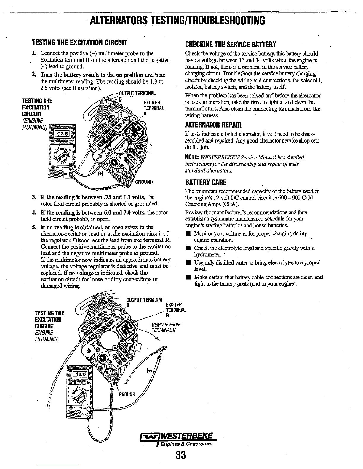
ALTERNATORS
TESTING/TROUBLESHOOTING
TESTING
1.
Connect the positive (+) multimeter probe to the
excitation terminal R on the alternator
(-) lead to ground.
i.
'furn the battery switch to the on position and Mte
ille
multimeter reading. The reading should
2.5
volts (see illustration).
TESTING
EXCITATION
CIRCUIT
THE
3.
'If
the reading is between
rotor field circuit probably is shorted or grounded.
4.
If
the reading is between 6.0
field circuit probably is open.
5.
If
no reading is obtained, an open exists
alternator-excitation lead or in
ille regolator. Disconnect the lead
Connect ille positive multimeter probe
lead and
If
the multimeter
voltage, the voltage regulator
replaced.
excitation circuit for loose or dirty connections or
damaged wiring.
THE
EXCITATION
ille negative multirneter probe to ground.
now
If
no voltage is indicated, check
CIRCUIT
.75
indicates
and
the negative
be
and
1.1
volts, ille
and
7.0 volts, the rotor
in
ille excitation circuit
from
exc terminal R.
to
the excitation
an
approximate battery
is
defective and must be
the
the
1.3
to
of
CHECKING
Check the
have a voltage
running.
charging
circuit
isolator, battery
When
is
back
'terminal
wiring
ALTERNATOR
If
tests
sembled
do the job.
NOTE:
instructionsfor
standmd
BATTERY
The
minimum
the
engine's
Cranking
Review the manufacturer's recommendations
establish'a systematic maintenance schedule
engine's starting batteries
• Monitor yonr voltmeter
engine
• Check
hydrometer.
Use,
•
leVel.
• Make certain that battery cable connections
tight to
THE
SERVICE
voltage
If
circuit.
by
checking
ille
problem
in
operation,
studs.
hamess.
between
not,
illere
Troubleshoot
switch,
Also
of
ille
is a problem
ille
has
been solved
take
clean
REPAIR
indicate a failed
and
repaired.
Any
WESTERBEKE'S
the
disassembly
alternators.
CARE
recommended capacity of ille
12
volt
DC
Amps
(CCA).
operation.
ille
electrolyte level
'
only
dis1illed
ille
battery
water
posts
BATTERY
service battery. this
13
and
14
volts
in
ille
the
service battery charging
wiring
and
connections,
and
ille
battery itself.
and
the
time to tighten
ille
connecting
alternator,
Service
control circuit
and
it
will
good
alternator service
Ml1JlUl11
and
repair
is
house batteries.
for
proper
charging
and
specific
to
briog electrolytes
(and
to yonr
when
service
before
and
terminals
need
has
of
600 -
gravity
engine).
battery
ille
engine is
battery
ille
ille
alternator
clean
to
be
shop
detailed
their
battery
900
and
illen
for
yonr
during
to
are
should
solenoid,
the
from
the
disas-
can
used in
Cold
wiill
a
a proper
clean and
TESTING
THE
EXCITATION
CIRCUIT
ENGINE
RUNNING
OUTPUT
TERMINAL
EXCITER
TERMINAL
R
Engines
33
& Generators
Page 44
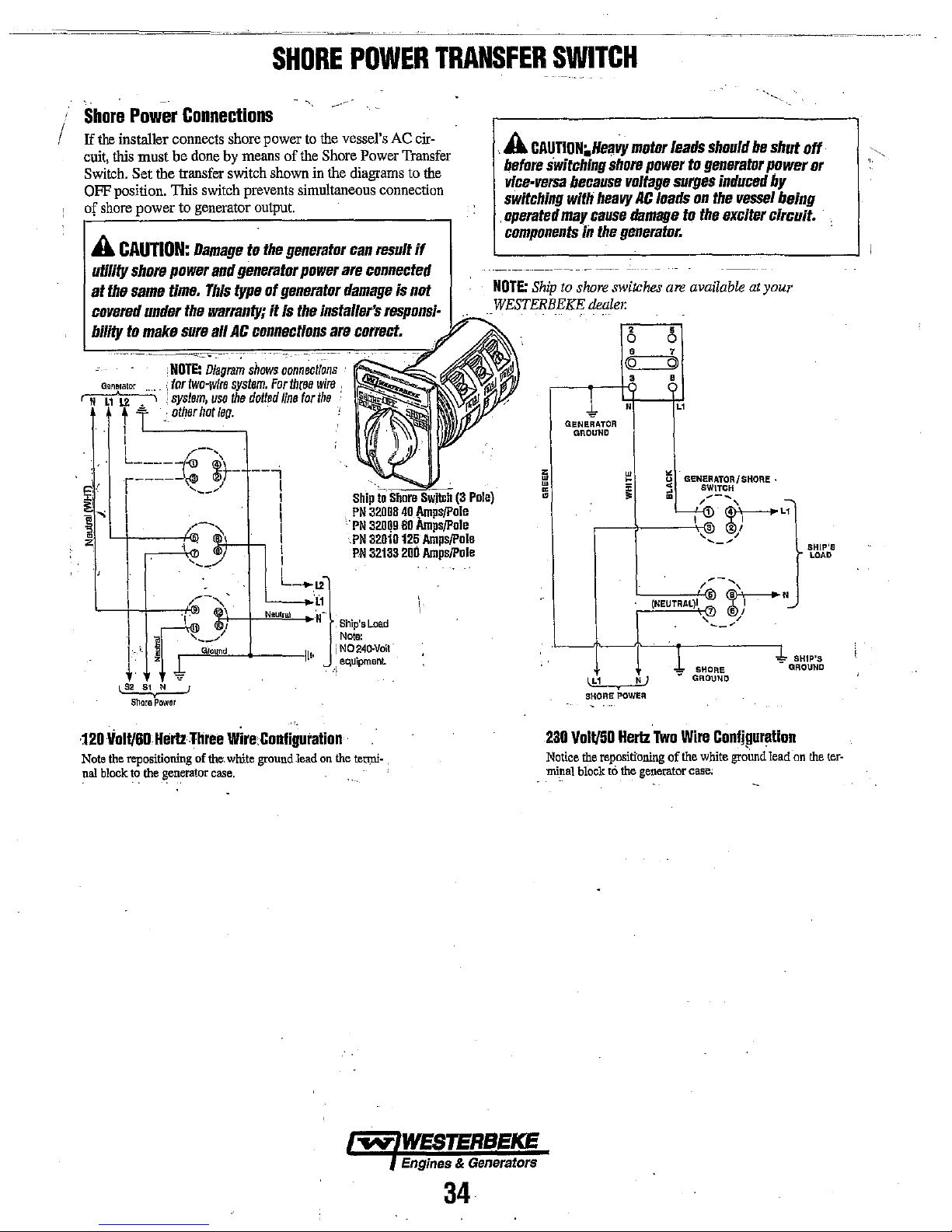
Shore
Power
If
the
I
installer connects shore power
cuit,
this must be
Switch.
OFF
of
Set the transfer switch
position.
shore
A
CAUTION:
utility
shore
at
the
same
covered
bility
to
Generator
~
t ~ :
I
I
I
L
____
r-----~
I ,
\
L.-+-+---f·I~
···.'
t
~
Shara
Connections
done
TIris
switch
to generator
Damage
power
time.
This
under
the
warranty;
make
sure
,NOTE:
Diagram
(
for
two~w(re
:
system,
other
hotleo.
/'"--','
-I'll
__
,--~
.-_""1;1)'
.......
-.
_
1---
e ,
__
~
~._
"'","''"'''"'-+----11'· i
f?
Power
and
all
use
~,_
<'!.if
....
~,
...
"J
.....
' ' .
/
SHORE
to
the
by
means
of
the
Shore
shown
in
prevents simultaneous
output.
to
the
generator
generator
type
AC
connections
shows
system.
the
dotted
power
of
generator
it
Is
the
oonneot;ons
For
th(Be
line
for
installer's
wfre
the
--,
I
I
i
I
....jl-,
I
I
I
L-.L2}'
'---.;(1
Neutral
'N-'
.
POWER
vessel's
Power
the
diagrams
connection
TRANSFER
AC
cir-
Transfer
to
the
'.
.
can
result
if
are
connected
damage
are
correct.
Is
not
respons/·
NOTE:
WESTERBEKE
.
,
.
Ship
10
PN
32008
.
PN
32oQ9
PN
32010
PN
32133
,Ship'sLoad
Note:
NO~40.Volt
equipment
:\
.
40
Amps/pole
80
Amps/Pole
125
Amps/pole
200
Amps/Pole
(3
Pole)
SWITCH
A
CAUTlON.Hellv,
before
switching
vlce·versa
switching
operated
components
Ship
•
because
with
may
iii
to
shore
1
GENERATOR
GROUND
lL1
SHORE
shore
heavy
cause
the
generator.
switches
dealel:
POWER
motor
leads
power
voltage
cQ
w
;;
"
•
surges
AC
loads
damage
,
0
•
•
N
to
are
5
0
7
Q)
•
L'
~.
U GENERATOR/SHORE·
5
•
~~L1
(NEUTRAL)I
~
N)
should
to
generator
induced
on
the
vessel
the
exciter
available
SWITCH
...-....
~
2 I
, I
~-~
1';,.-
.....
,
~N
• I
, /
--'
SHORE
GROUND
be
at
1 '
shut
power
by
being
circuit.
your
-
SHIP'S
1.
GROUND
off
or
SHIP'S
LOAD
·120
Yolt/60.Hertz
Note
the
repositioning
~al
block
~o
the
generator
Three
wire:Configuration
of
th~.
white
case,
ground
lead
on
the
.
teupi-
,
Engines & Generators
230
Volt/50
Notice
the
.mi~al
repositioning
block
Hertz
to
the
Two
Wire
of
generator
Conlipuralion
the
white
ground
case;
lead
-on
the
ter·
34
Page 45

USE
OF
ELEGTRIC
The power
more
Some
others. Split-phase
under
monly
machines,
started,'
7 times
avoided,
ven
motors require
to
rUn.
load
compressor,
motor
In
general,
to
medium
*NDTE:
more
for this
made
Because the
motors
damaged
be
seconds.
all
off
on
the electric
Required
Run the
generator's
indicted
should be
the
generating
voltmeter
and load,
NOTE:
contains
tim!
vide
panel.
required
than
is
motors
similar
used
on
or
such
as
much
whenever
by a small
The
current required
connected
for
to
which
the
slllI1ing
MOTOR
SIZE
(HP)
1/6
1/4
1/3
1/2
3/4
1
In
the
for
some
is
tim!
in
lJ2rger
heavy
is
required
if it
If
difficulty
other
electrical loads
Operating
generator
capacity,
on
the
checked
or
ampere
check
When
the
AC
equipment
the
generator's
one
120
This
will
required
require
circumstances,
where
as
generator.
from 2 to 4 times
current
above
s111nlll1wtors
the
sizes.
motor.
generator's data
plant and the
volt
generator.
MOTORS
to start
an
to
keep
much
more
(AC)
motors
easy-starting
loads
are
small
power
current
to
start
possible, if
Capacitor
to
it.
An
electric
example,
no
loads
hardest
can
load
is
reqnired
will
(AMPERES)
table
surge of
for
only
bring the
is
experienced
will
connected.
he
AMPS
RUNNING
3.2
4.6
5.2
7.2
10.2
13
the
starting
current
an
and,
Speed
first with
periodically
it with a
vessel
AC tenninalblock
AC hot
ensure
and
finally
meter
pOltable
in
of
good
no
appliances
is
which
120
leg
electric
motor
it
running
current
require
than
other
loads,
such
applied
tools.
to
to
after
Because
as
to
run,
the
electric motor
and
as
much
start
any
motor
connected
require
more current than a
start
115-Volt
approximately
FOR
maximum
than
for
lJ2rger
types
needed
instant,
the generator will not
motor
up
in
starting
if possible,
load
applied,
loaded
plate.
The output voltage
to
ensure
not
insralled
meter and
the
generator
volts
only,
be
for
the
vessel's
I1wtDr
sta.ting
GENERATOR
INFORMATION
Generator
is
considerably
after
it
is
started.
to
start
them
than
more current
types.
as
washing
the
they
their
repulsion-induction
current
motor
motors
as
AMPS
{~TARTIN~l
AMPERES
6.4
9.2
.
10.4
14.4
20.4
Amps
ones.
(split-phase)
for
to
speed
reduce
then
to
its
full.capacity
proper operation
it
supplies.
to
monitor
amp
it
is
configured
to
start,
They
are com-
motor
is
require 5 to
use
should be
is
to
be dri-
to
start
as
varies
with the
to
an
air .
connected
follows:
FOR'
to
22.4'
to
32.2'
to
72.S'
to
29.2'
to
40.S'
26
to
52
for
Starting
The
reason
are
not
starting
in a few
motors,
is
tum
the load
at
half the
If
an
voltage
probe.
installed
as
of
AC
recommended
to
pro-
is
distribution
response
from
the
Frequency
indicated
•
•
Therefore,
generator's
dipswitch
generator
sensing
Generator
•
• For
•
• The drive
• The rear
• Examine
Frequency
is a direct
by
111e
When
the
generator
output
frequency
When
the
generator
output
frequency
to
change
drive
on
the
changed
PC
board
Maintenance
Maintaining
Connections
become
ducting
allowed
cause
leum-base
surfaces
suggested are
410" and
In
inspected
of overheated
checked
and for
should
accelerate
to
8,
ners
maintenance
noisy
of shaft
motion
shaft of
Repair
rub
corroded,
if
salts,
to
excessive
unusually
to
Ashland
addition
for
discs
periodically
any
not
cracking.
the
generator
identified
of
the
armature
or
rough-sounding,
bearing
should
is
detectable,
bearing
Il).ust
and
cause
build
coatings,
reduce
to
be
head.
Adjustment
result of engine/generator
following:
is
run
at
1800
RPM,
is
60
Hertz.
is
run.at
1500
RPM,
is
50
Hertz.
the generator's frequency/voltage,
engine's
ECU.
changed.
reasonable
of tenninal
severe
Daubert
periodic
(a)
terminals
evidence
allowed
by 6 radial
is
required.
be
be
major
speed
The
AC
output
and
the
connections
cleanliness
boards
and
insulation
dust,
engine
exhaust,
up.
Clogged
heating
on
shaft
socket
made
and
reduced
conditions,
should
be
rusting
and
Chemical
"Tectyle
tightness
single
bearing
at
detected
506"
cleaning,
of
all
and
(c)
bearing
if possible
of incipient cracking
to
become
The
bolts
must
be
marks,
is
lubricated
However,
have
periodic
damage
intervals.
when
bearings
outside
quickly
to
must
be changed using
configuration of
on
is
important
and
rectifiers
surfaces
carbon,
ventilation
life
thin
rust-inhibiting
sprayed
corrosion.
Co.
"Non-RustAC-
or
equivalent.
the generator
connections, (b)
loose
or
generators
for
tightness of
rusty
which
fasten
hardened
one
at
each of
if the
it
replaced.
No
force
are
wearing
bearing
or
major
generator.
speed,
theAC
theAC
the voltage
may
may
start
etc.
openings
of
windings.
or
brushed
'TYpical
should
evidence
damaged
should
screws
failure.
because
steel
and
is
has
components
rust
the
drive
SAE
the 6 cor-
sealed;
bearing
side
movement
applied.
or
wear
OCCUlTed.
as
voltage
voltage
the
111e
111e
con-
are
may
petro-
over
all
materials
be
wires.
be
Discs
may
disc
grade
no
becomes
if
side
on
will
...-N"
WESTERBEKE
Engines &
35
Generators
Page 46

DESCRIPTION
The
Be
generator
requires
output.
windings
started, residual
voltage in
larger
voltage
quickly
regulated
same
the
AC
The
A
the
The
ratings
inside of
v.Ji.ous
as
only the
The
voltage
in
reaches
time,
stator
tenninalsto operate
generator
liS
volt
SPECIFICATIONS
generator
of
the
AC
in
this
manual.
drive
stator
and
the exciter
magnetism
the
stator
in
the
the
four rotating
the
energy
field
this
regulated
windings
is a single
AC
two
data plate
the
generator. An
louvered cover
voltage
---
NOTE:
and
is a brushless;
force
houses
windings
exciter
saturation point of
is
which
wire
section
connections
of
the
two
sets
windings.
in
the
which
windings.
poles
then
maintained
field
produces
can
then
AC
equipment.
phase,
or
230
volt
of
gives
the
AC
at
the
....
self~exciting
and
120
wiring
are
---=--~,~~--=------.----.-~---
Be
GENERATOR
WESTERBEKE
adjustments
generator
engine
to
produce
of windings;
When
four
rotating
then
This
in
the
be
drawn off
volt
two
this
manual
voltage,
decal
generator
provided on
the
the generator
poles
generates an
mutual
the
exciter
capacitor(s)
in
the
stator.
a steady
the
AC
two
wire
at
50
for
current and
is
affixed
end.
recommends
be
performed
which
an
main
is
induces
even
buildup of
windings
and
At
AC
voltage
generator's
wire
at
Hertz.
generator
frequency
to
Diagrams
this
decal
AC
stator
a
the
60
Hertz.
Refer
ratings.
the
of
as
a
in
the
well
SINGLE
that
the
by a qualified
Circuit
A circuit breaker
WESTERBEKE
automatically
electrical overload. The circuit breaker can
off
when
coming
NOTE:
add-on
WESTERBEKE
60
Hz
50
Hz
to
PHASE
following generator
technician.
Breaker
is
installed
generators.
disconnect
servicing the
into
the
This
circuit breaker
kit for earlier
- 5.5 KW
- 5.0 KW Circuit
boat.
dealer.
Circuit
generalDr
model
Breaker
Breaker
tests
This circuit breaker will
generator
is
generators;
on
all
single
power in case of
to ensure
available
Part
Number
Part
Number 042238
phase
an
be
manually shut
that
no power is
as a WESTERBEKE
contact your
038209
INTERNAL
A
ROTATING
WITH
DIDOES.
B
MAIN
STATOR
C
EXCITER
CIRCUIT
BC
GENERATOR,
WIRING
r-------
I
I
I
I
I
1
I
I
. I
I
1 .
1
AI
I
I
I
l
UIUIJtl~:::
I I
I I
I 1
1 1
L
_____
FIELD/AUXILIARY
WINDINGS.
WINDINGS
AND
....
-"'1
..:
___ J
WINDINGS
CAPAClTOR(S).
r----------,
1 I
I I
~----_(:l2
--.,-----<:I~
------<::>4-=
L~~======~~
____
I
"'"
"'I
9 I
"'I
;;!
I
I
~IB
~1
. I
I
I
.1
r--------
I I
: I
1
C
I ,
\ t
________________
AC
TERMINALBLOCK
---
..
----
---'
5~
CAPA!~
t
CAPAI~
l
..1
Engines & Generators
36
DUAL
EXCITER
CIRCUIT
Page 47

Be
NOTE:
WESTERBEKE
and
adjustments
GENERATOR
re.commerufs
be
peiformed by a
SINGLE
that
the
qualified
PHASE
following
technician.
generator
==--'--
tests
SINGLE
1.
2. Start
3. Refer
4. Shut
EXCITER
Remove
generator,
the
five
generator
current
~ppliances).
.
correct.
correct
configuration
by
hot
reading.
at
lower
plugged
A
handling
tial/y
power
the louvered
covering
capacitor(s).
the
generator
minutes
measuring
lead
60.5 -61.5
so
the
is
operating
from
the
Make
Adjust
the
engine
speed
to
the
AC
then
the
with a volt
The generator's
Hertz.
than
specified,
off
the
generator.
into
the
WARNING:
as
they
lethal
charge
source.
NO-LOAD
the
and
engine
generator
sure
governor
load
check
voltage
meter.
capacitor.
CapaCitors
stote
even
VOLTAGE
metal
plate,
AC
tenninal connections
allow
can
without
(that
the
engine's speed
as
before
proceeding.
connections
the
across
Make
no-load
If
the
voltage
proceed.
Make
must
electricity
when
ADJUSTMENT
at
the back of
it
to
run
for
wann
up.
Make
any
equipment
is,
shut off
needed
generator's
sure
disconnected
to
diagram for
no-load
the neutral
sure
you
voltage
is
output
the
60Hz
be
discharged
and
can
the
and
approximately
sure
the
drawiug
all
electrical
(Hertz)
is
obtain
the
the
correct
voltage
lead
and
the
record
this
115 -124
is
higher
Hertz
volts
or
lead
before
pack a poten-
from
their
AC
is
S.
There
minal,
low,
then
nect
the plug
tor's oo,load
numbered
number.
terntinal
6.
If
the
because
numbered
or
the
bered
Generator
A
covers
are
NOT
.
with
are
three
plugs
grouped
#7,
#8,
and
#9.
If
disconnect
plug
Note
may
generator's no-load
the
voltage
plug
voltage
plug
is
Troubleshooting
WARNING:
on
the
in
the
generator's
the lower
with
the
next
voltage
is high,
and
connect
that
the plug
be
anyone
needs
is
already connected
needs
to
be lowered
connected,
Make
unused
contact
with
housing.
for
the
right capacitor
the generator's no-load
numbered
higher
then
the
plug with the next
presently
of
the
three
voltage
to
be
increased and the
refer
to
the
Guide).
cerlain
leads
are
each
other
NOTE:
SHOWN
DEMONSTRATION
THESE
BEMADE.
plug and
number.
disconnect the
cannot be adjusted
and
th';
in
If
the
connected
plugs
available.
to
the right
the
lowest
WESTERBEKE
ins~/ating
place
and
Dr
In
contact
THE
#7
WIRE
CONNECTED
CONNECTIONS
OF
voltage
coogenerahigher
lower
to
this
highest
terntinal,
num-
IS
AS
A
HOW
CAN
ter-
is
BC
NOTE:
Simply
insulated
any
excess
A
WARNING:
voltage
The
capacitor
Touching
shock.
voltage
could
rolllr.
cross
(plastic
handle)
electricity.
adjustment
can
any
wiring
In
addition,
adjustment
cause
your
the
capacitor's
Do
not
while
screwdriver.
attempt
the
generator
two
to
produce a 400-500
can
produce a severe
attempting
while
fingers
the
generator
to
be
to
make a no-load
caught
terminals
This
will
with
discharge
make a no·load
is
operating.
volt
charge.
electrical
is
operating
in
the
generator's
an
BC'
GENERATOR
//
BACK
120V/6DHz
/
/.
/
,
END
SHOWN
SINGLE
-
.
AC
TERMINAL
BOARD
\
EXCITER
CIRCUIT
.
See
the
ENGINE ADJUSTMENT
ADJUSTING
THE
ENGINE
section
SPEED.
REFER
AC
in
this
manual
TO
THE
FOLLOWING
TERMINAL
BLOCK
for
PAGE
FOR
CONNECTIONS
lit..
.,
Engines & Generators
37
Page 48

120
I
I
VOLTS
60
120v
BC.GENERATQRSINGLE
AC
TERMINAL
HERTZ.CONNECTIONS
60
Hz
BLOCK
AND
VOLTAGE
SENSE
VOLTAGE
TO
CIRCUIT
BREAKER
PHASE
BOARD
SENSE
BlK
CONNECTIONS
RESISTOR
BOARD
FOR
60Hz UNIT
U)
....
'"
o
-w
...
"'"
NUU
0-'"
"""''''
..
UaJ
WHEN
WIRING
A
JUMPER
LOAD
CONNECTIONS.
115
VOLTsAMD
115v
50
Hz
N
,
".
50
-
02
IS
LI
3
6
120V/60Hz,
REQUIRED
230
BETWEEN
VOLTS
50
HERTZ
230v
LI
4(]K)3
50206
50
Hz
VOLTAGE
\1
VOLTAGE
RESISTOR
SENSE
TO
CIRCUIT
BREAKER
WHT
IlL
·'1
RlK
(1)
SENSE
BOARD
#053762
RESISTOR
o (.AI
r
z
r"
..
~
N
I
~
cc=ItI
c:c:::Jt::t
cc::::::b
oc:::>o
5Jln
n
"OJ
cre:::3=I z
c:c:JI=;Il
c:c:::::Ita
oc:::::>o
BOARD
:z:
"'("1
FOR'
BlK'
z
..
>
GR~
0
~
WH
,.
RED
.:AC
;fROM
....
50Hz
SENSE
.
UNIT
CABu'.),
HARNESS'
. '
'"
!
LOAD
CONNECT!
ON
LOAD
CONNECTION
oW
WESTERBEKE·
'Engines & Generator.
38
VOLTAGE
RESISTOR
#053762
SENSE
BOARD
Page 49

DUAL
EXCITER
These
generators
ment
connectors
available
selection,
and
#9,
When
making
proceed
1.
Shut
2.
Select
capacitor
RPM.
and
#9,
duced
can
be
increase
between
achieve
CIRCUIT
have
at
each
for
each
capacitor.
60
Hertz
or
are
for
no-load
Hertz change or
as
follows:
the
generator
the
appropriate Hertz connection
#60,
60
The
three
other
will
have
by
the
generator.
plugged
into
or
decrease
connectors
the
prescribed
MODEL
dual
Hertz
capacitor.
TWo
50
Hertz,
voltage
down.
Hertz,
1800
connectors
an
effect
One
each
capacitor.
approximately 8 -
used
in
no-load
5.0KW
and
There
connectors
and
adjustment.
no-load
RPM
on
the
connector
any
pair
voltage
Be
no-load
are
three connectors, #7,
voltage
to
or
50,
at each
no-load voltage
from
No-load voltage
10
combination
as
GENERATOR
voltage
five
are
plug
#50
capacitor,
AC
illustrated
adjust-
connectors
for
Hertz
adjustments
into
each
Hertz,
#7, #8,
pro-
each
group
will
volts
to
below.
#8,
NOTE:
insulated (plastic handle) screwdriver. This will discharge
any
1500
SINGLE
A
WARNING:
handling
tially
power
as
lethal
source.
Simply cross the capacitor's two terminals with
excess
PHASE
Capacitors
they
stol'l1electrlclty
charge,liVen
electricity.
must
and
when
disconnected
be
discharged
can
before
pack a poten-
from
their
an
50HZ
r.nNNFr.Tlnl'~~
NOTE:
When changing Hertz produced by the generator, an
be
engine speed change must
The AC output connections on the terminal block
selectedfor
connection (s) on the capacitor(s) changed
from
wire
correct neutral
the voltage
the neutral
terminal.
of
made. This is done
and
Hertz to be produced. the Hertz
and
the AC terminal block moved to the
at
the
ECu.
must
be
the ground
,
,,/60
Hz
120
DDAL
EXCITERCIRCDIT
VOLT
CON.FIGURATION
,
A
WARNING:
the
unused
with
each
leads
other
Make
or
ILLUSTRATION.J
::;:;".",A!;
are
in
in
contact
certain
place
the
and
with
IEFIMINAL
insulating
are
NOT
the
generator's
BOARD
covers
in
contact
on
...
REFER
TO
THE
PREVIOUS
~',
AC
TERMINAL
PAGE
BLOCK
CONNECTIONS
FOR
'
-..v'
WESTERBEKE
Engines &
39
Generators
Page 50

~------'-------~~~-----===-~~~------
I
~
~
The
following
insight
into
problems
single
ahd
dual
the
simplicity
is
relatively
effect
Keep
electricity
easy,
is
·understood.
in
mind
is
remember that
therefore,
a
generator.
Only
These
meter
extreme
Ii
few
are
hand
capable
basic
sion required
No
AC
Output.
Residual
voltage
at
NO·Load.
High
AC
Output
Low
AC
Output
Voltage
Orop
No
Battery
Charge/Low
Unstable
voltage
5.5/5.0KW
troubleshooting
which
capacitor
of
the
equipment
once
the
that a basic
required
Problem
Under
lethal
caution
tools
tools:
of
reading
in
reading
4 -6
VAC
at
No-Load.
60·106V.
Load
output.
for
voltages
are
an
component
(Hot
or
Battery
chart
may
be
Be
brushless
and
relationshlp
fundamental
this
troubleshooting,
are
present
is
essential when
necessary
amp
probe
less
than
to
N)
-
at
No-Load.
Charge
EDe
is
designed
encountered
generators.
controls,
between
knowledge
in
the
troubleshooting
for
diagnosis
and a quality
one
ohm
due
winding
1.
Shorted
2.
Open
3.
Shorted
1.
Faulty
2.
Open
3.
Shorted
4.
Electrical
1.
Faulty
2.
Incorrect
3.,
Incorrect
1.
Faulty
2.
Faulty
3.
Faulty
1.
Faulty
2.
Faulty
1.
Faulty
2.
Faulty
3.
Blown
4.
Faulty
1.
Electrical
GENERATOR
to
give
with
the
Owing
to
troubleshooting
cause
and
of
and
always
circuitry;
and
repuir.
volt-ohm-
to
the
preci-
resistances.
Probable
stator.
capaCitor.
Exciter.
rotor
rotor
diode.
capacito,
diode
capacitor.
bridge
Cause
stator.
diodes
(two).
exciter.
connections
winding.
capacitor.
hertz
tap
winding.
..
rectifier.
integral
controiler
fuse.
winding.
connections
faulty.
on
capacitor.
are
Before
the
witnessing
light a problem
rather
Bring
problem
that if
replaceable
efficiently.
..
faulty/loose.
TROUBLESHOOTING
attempting
problem
than
basic
equipment,
the
problem
1.
2.
3.
1.
2.
3.
4.
1.
2.
3.
1.
2.
3.
1.
2.
1.
2.
3.
4.
1.
any
repairs,
as
possible,
the
problem.
which
equipment
repair
parts,
tools
such
should
the
problem
preferably
In
is
related
fault.
with
as:
be
VerilicationJRemedy
Check
stator
windings.
Check
stator
windings.
Check
diodes
on
rotor.
Check
capacitor.
Check
exciter
windings.
Check
exciter
windings.
Inspect/clean
Correct
Verify
Connect
Check
Check
Verify
Check/replace
Verify
Check
Troubleshoot
Inspect/replace
Check
Check/clear/tighten
and
tighten
connections.
capaCitor
rating.
correct
hertz
rotor
winding.
diodes.
capaCitor
rating.
diode.
capacitor
ratings/replace.
rectifier
diodes.
controiler.
30
charge
circuit
gel a clear
some
cases,
to
you
on
diodes
found
can
connections.
tap.
amp
fuse.
windings.
electrical
an
explanation of
from
an
individual
this
may
the
method
the
initial
and
bridge
in
one
of these easily
be
remedied
connections.
bring
of
trip
rectifier,
early
to
operation
to
the
so
and
Noisy
Operation.
112
AC
Voltage
Output
1.
Faulty
2.
Generator
to
1.
Faulty
2.
Faulty
support
engine
Exciter
Rotor.
rotor
is
loose.
Circuit.
bearing.
connection
Engines.
~.
& Generators
40
1.
Inspect
2.
Inspect
1.
Check
2.
Check
rear
rotor
securify
exciter
rotor,
carrier
of
circuit
diodes
bearing:
rotor
to
flywheel.
components.
and
windings.
Page 51

LAY-UP & RECOMMISSIONING
,
I'·
GENERAL
Many
owners
rely
on
their
boatyards
including engines
off-season
to
accomplish
The
procedures
own
lay-up
list
procedures
you
have
local
if others
lay-up
assistance.
check
These
during a
maintenance
If
your
provide
Propeller
The
transmission
be
opened
'out
of
the
water
storage
in
severe
strain
the
boat
is
shaft
has
actually
apply
to
small
not
in
use,
period
oftime
Fresh
Water
A
50-50
solution of
recommended
This
solution
antifreeze,
solution
Should
amount
mixture.
and
cooling
to
more
from
Operate
mixture
system.
Lubrication
With
the
engine
sump.
Remove
with
new
ENGINE LUBRICATING OIL
oil
changing
oil
pressure
A
CAUTION:
in
the
sump
combustion
chemicals
internal
and
or
for
long
lay-up
which
and
recommissioning,
do
should
and
also
needs
of
any
questions
servicing
Shaft
up
the
taken out
unless
and
or
cradle.
on
the
boats
..
and
the
been
they
dealer;
Coupling
moved
propeller
Cooling
antifreeze
for
use
may
require
depending
make
sure
antifreeze
the
engine
the
of
the
antifreeze
Now
System
warm,
and
replace
oil.
Use
the
procedure.
and
make
00
over
the
deposits
Which
parts.
generalnrs,
periods
preparation
follow
the
procedures.
afford
help
your
engine.
regarding
propeller
bolts
from
The
flexibility
or
put
bent
that
are
have
Circuit
in
the
a
on
the
the
antifreeze
be
needed,
block
engine
recheck
drain
correct
Run
sure
not
leave
lay-up
combine
can
reduce
to
prepare their
for
lay-up
during
of
inactivity.
themselves.
will
allow
or
your
familiarize
he
will
be
you
you
engine
you
lay-up
more
Others
to
may
protection
with
procedures,
than
[Propulsion
half
couplings
removed
in
by
hauled
been
coolant
higherco~centration
to
the
there
when
the
land
to
water,
of
the
boat
shaft
or
coupling
the
water.
In
some
these
strains.
out
of
the
dry
for
a considerable
and
distilled water
system
area's
winter
climate.
protection
drain
an
appropriate
and add a more
ensure a complete
concentration
the
antifreeze
all
the
oil
grade
pages
the
engine
are
the
period.
to
the
throughout
engine
filter
and
of
oil.
Refer In
in
this
and
no
leaks.
engine's
Lubricating
produce
life
of
your
This
at
solution's
oil
fill
manual
check
craft,
the
prefer
perform
use
them
the
call
willing
Engine]
should
always
boat
is
hauled
and
during
often
puts
or
both,
while
cases,
the
does
not
water
when
is
all
times.
of
Check
is
adequate.
concentrated
circulation
the
strength.
from
the
the
sump
the
for
for
proper
old
engine
all
and
harmful
engine's
your
as
a
to
a
the
oil
the
oil
Fuel
System
Top
off
or
higher. A fuel
stabilizer should be
gasoline/water
and
make
fuel.
Fuel
System
Top
off
additives
mix
with
Additives
should
be
condition
used
are
separator
primary
sediment
Change
fuel
system,
for
5 system.
the
fuel
needed.
allow
movement
equipment
Raw
Water.Cooling
Close
the
hose
from
gallon
bucket
check
the
the
engine
any
zinc
zinc
anode
Start
the
fresh
water
stop
the
solution
protection
Start
the
through
the
engine.
water
circuit from freezing
as
providing
Remove
antifreeze
Examine
a
cover
until recommissioning, but
Cylinder
Spray
arrester
oil
will
spark
[GaSOline]
your
fuel
tanks
conditioner
added.
separator
certain there
are
[Diesel]
your
fuel
tanks
should be added prior
the
fuel
being
such
as
Bio-bor
added
at
this
the
fuel.. Care
compatible
used
fuel
bowl.
the
fuel
10
minutes to
Check
system during
Operating the
on
through-hull
the
zinc anode
and
debris from
is
engine and
through
engine and
slightly
in
engine
the
This antifreeze
the
mixture
the
gasket
with
in tbe
system.
filter/water
filter
elements
as
needed.
make
for
any
this
engine
of the treated
the
engine.
seacock. Place
of clean
found
clean
or
inside
located.
your area ..
raw
cOlTosion
impeller
impeller.
Clean
allow
the
refill
stronger
and
allow
water system
from
will
Do
not
Lubrication[Gasoline]
fogging
plugs
oil
removed.,
stall
out the engine
for
winter
into
while
with
unleaded
such
Change
and
clean
no
with
No.
added
and
time
to
should
the
primary
Change
separator
Start
the
sure
leaks
that
servicing,
leaks.
as
Sta-Bil gasoline
the
the
Clean
2D
diesel
to
topping
and
fuel
Diesel
Kleen
control
be
taken
fuel
the
and
on
the
engine
no
air
may
correcting
for
5 -
10
fuel
through
gasoline
element
metal
bowl.
up
fuel.
off
still
in
+ Celane Boost
bacteria growth
that the
filter/water
element
clean
the
engine and
and
is
left
have been
minutes
the
Circuit
seacock.
fresh
replace
protection.
accompany
Acquire a replacement,
replace
the
protection.
the
water.
in
the
the
the
system.
the
bucket
than
all
mixture
during
your
replace
open
the
engine
and
Remove
end
Before
the
primary
it
as
heat
raw
raw
water
When
needed
of
this
Once
should
the
raw
the
impeller
air intake,
coat
the
of this hose
starting
heat
required,
exchanger
water
strainer.
pump
the
bucket
with
an
for
winter
mixture to
the
bucket
protect
winter
water
pump
it,
so
catch
the
cover
with
is
running.
the
valves,
of
89.
in
your
Re-install
any
spilled
Fuel
to
ensure
the
tank.
additives
in
separator
bleed
allow
it
in
the
fuel
created
themas
will
injection
raw
water
into a five
the
exchanger
and
also
where
to
draw
is
antifreeze
freeze
be
drawn
is
empty,
the
lay-up,
(some
it
in
if
needed,
(into
the
and
gasket.
the
The
cylinders
octane
they
and
your
the
to
run
in
help
intake
engine,
on
clean
the
the
empty,
stop
raw
as
well
a bucket).
and
pump)
flame
fogging
and
Engines & Generators
41
Page 52

LAY-UP
&
RECOMMISSIONING
Starter
Lubrication
if
battery connections
the
connections removed
Cylinder
If
WESTERBEKE
access
the
revolutions
If
to be
the
Intake
Clean
cloth
block
through-hull exhaust
to
Cylinder
After engine
small
crankshaft manually
spark
NOTE:
the crankshaft two full
tighten properly and connect
each spark plug.
Motor
and
cleaning of
access
to
the
starter
starter.
Take
care
Lubrication
you
anticipate a
recommends
to
the
cylinders.
cylinder
your engine does
injectors
walls.
and
removed.
and
re-install
Be
return
Manifold
the
filter
screen in
lightly
soaked
any
opening.
start-up!
Lubrication
shutdown,
amount
plugs
of
loosely
At spring
fogging
commissioning,
perntits
are
shut
in
properly
from
[Diesel]
long
lay-up
Squirt
Rotate
the
the
not
have
sure
to
have
fuel
[Gasoline]
the
in
lube
Also
place
port,
Make a note
[Gasoline]
remove
oil
two
complete
for
winter
revolutions.
Batteries
If
batteries
make
to prevent them
batteries will
subjected
batteries
environment.
A
highly-explosive
arcing
smoke
serviced.
to
Transmission
Check
off
the coupling
coating.
additional information, refer
are
to
be
sure that
to
and
they
from
not
remain
severe
store
WARNING:
or a lighted
or
allow
Shut
off
prevent
grime
or
change
and
Check
electrical
[Propulsion
the
grease
and
the
that
left
on
are
fully
freezing.
fully
environmental
them
in a warmer,
Lead
acid
gas,
Which
cigarette,
an
open
all
electrical
arcing
fluid
in
and
touch
output
the
transntission vent
the
starter
drive
pinion
its
easy
removal.
off
before
attempting
replacing
the
starter.
period
(12
removal
some
engine
glow
glow
line
flame
oil
around
an
into
lay-up
the
board
charged,
If
charged,
of
Marvel
crankshaft
plugs.
plugs,
replacement
as
needed.
arrester,
the
oil-soaked
to
the
spark
each
cylinder.
revolutions.
remove
Re-install
high tension leads fully onto
during
and
there
is
or
conditions,
more
batteries
can
be
ignited
cigar,
or
flame
near
the
equipment
during
servicing.
Make
any
electrical
months
the
glow
Mystery
the
injectors
sealing
and
flame
cloth
remove
plugs
Rotate
Re-install
the
plugs and
the
the
lay-up
will remain
any
doubt that
that
they
remove
compatible
emit
hydrogen,
by
pipe.
battery
in
by
place a clean
and
Do
Engine]
the transntission
up
any
flange
with
to
the TRANSMISSION
as
unpainted
an
anti-corrosion
is
open.
is
advisable,
sure
to
remove
or
!Dare)
plugs
for
Oill
into
hand
two
will
washers
arrester
to
in
the
cloths
prior
spray
the
the
rotate
spark plugs,
period,
that
the
will
be
the
a
electrical
not
being
the
vicinity
required
areas.
Protect
For
SECTION.
the
have
for
a
way,
Wipe
Spare
Parts
Lay-up
Westerbeke
kit
or
coolant
and
during
SPARE
time
provides a
engine
hoses
order items
the
lay-up,
PARTS
section
to
see
need
replacement.
not
such
good
on
as
of
Recommissioning
The
recomntissioning
seasonal
those
section
However,
counteracted
1.
2.
3.
4.
5.
6.
lay-up
described
regarding preparation for
some
before
Remove
Remove
discard
removed
Install
Reinstall
lay-up,
terminals
Check
A
and
batteries
can
cigarette,
flame
electrical
arcing
Remove
proper
Check
circuit
that it
solution
engine
short period of
advisable,
service,
heat
area.
Start
in
manual.
the
the
the
during
the
raw
the
and
are
to
make
CAUTION:
eye
protection
emit
be
ignited
cigar,
near
the
equipment
during
the
tightness
the condition of the zinc
and
is
not
from
is
put into
to inspect
exchanger
the
engine in accordance
the
PREPARATIONS
of
your
generally
in
the
PREPARATIONS
of
the
lay-up
starting
oil-soaked
raw
water
old
gasket.
lay-up
water
pump
batteries
reconnect
clean
and
sure
that
Wear
rubber
when
hydrogen, a highly
by
electrical
or
pipe.
battery
in
servicing.
spark
plugs,
[gasoline}.
clean
or
replace
necessary
the
raw
operation,
time
with
as
either
an
the
and
clear
opportunity
if
external
hand,
filters
this
follows
the
cloths
pump
Install
(or a replacement,
that were
the
that the
items
Check
or
replace
and
zinc
manual.
Westerbeke
the
same
starting
procedures
engine.
from
cover
the
raw
cover
with a new
removed
battery
cables,
connections
the batteries
FOR
the intake manifold.
and
gloves, a rubber
servicing
batteries.
explosive
arcing
or a lighted
Do
not
smoke
being
serviced.
the
vicinity
wipe
to
flush
water coolant
no
end
area
any and
FOR
to
clean,
anode
the
anode
the
antifreeze/fresh water
the
system
adverse
of
season
where
the
all
with
STARTING
to
inspect your
such
as
drive belts
your
basic spares
those
items used
anodes.
and
will
water
are
Refer
engine after a
procedures
STARTING
normal
gasket and
if required).
during the
making
fully
starts.
need to
pump impeller
cover
sure
are
tight.
charged.
apron,
Lead
gas,
which
or
allow
an
Shut
off
all
prevent
re-gap,
as
system.
affects.
or
zinc
zinc
procedures
electrical
and
in
the
raw
needed.
will
recommissioning
When
self-flush
It
is
is
located
debris
section
Note
from
described
to
as
be
gasket.
the
acid
open
install
water
the
in
of
this
the
to
in
the
that
a
Engines & Generators
42
Page 53

POWER
TAKE
OFF
SYSTEMS
POWER
A
backend.
engine
The
horsepower
can
Or
Contact
power
for
EDC
be
utIlized
to
operate
TAKE
take
This
a variety of
generator's.
your
GENERATOR
BACKENO
OFF
ADAPTER
off
adapter
adapter
when running at
either
the power
Westerbeke Distributor
can
be
allows
accyss
hydraulic
drive
engine
for
AC
take
attached
and
1800
generator
off.
Not
to
the
generator
to
the
full
power of
electrical
is
producing a maximum
rpm.
both
for
accessories.
This
horsepower
amperage
additional information.
output
simultaneously.
the
STUDS
AND
HOLD
ACCESSORY
,ADAPTER
®@
POWER
TAKE
KITiI34786
HARDWARE
TO
THE
OFF
.
BOLTS
FASTEN
TO
GENERATOR
@~
ADAP~
HOUSING
__
~'!Il!ne~
&
Generators
43
Page 54

DECIMAL
TO
METRIC
EQUIVALENT
CHART
Fractions
an inch
11/64 0.171875
13/64 0.203125
15/64 0.234375
17/64 0.265625
19/64
21/64 0.328125
11/32 0.34375
23/64 0.359375
25/64 0.390625
13/32 0.40625
27/64 0.421875
29/64 0.453125
15/32 0.46875
31/64 0.484375
of
Decimal
1/64
1/32
3/64 0.046875
1/16 0.0625
5/64
3/32
7/64 0.109375
1/8 0.125
9/64 0.140625
5/32 0.15625
3/16 0.1875
7/32 0.21875
1/4 0.250
9/32 0.28125
5/16 0.3125
3/8 0.375
7/16 0.4375
1/2
(in.)
0.015625
0.03125
0.078125
0.09375
0.296875
0.500
Metric (mm)
0.39688 33/64 0.515625
0.79375 17/32 0.53125
1.19062
1.58750 9/16 0.5625
1.98437 37/64 0.578125
2.38125 19/32 0.59375
2.77812 39/64 0.609375
3.175
3.57187 41/64
3.96875
4.36562
4.76250 11/16
5.15937 45/64 0.703125
5.55625 23/32 0.71875
5.95312 47/64 0.734375
6.35000 3/4 0.750
6.74687
7.14375 25/32 0.78125
7.54062 51/64 0.796875
7.93750
.8.33437
8.73125 27/32 0.84375
9.12812 55/64 0.859375
9.52500
9.92187 57/64 0.890625
10.31875
10.71562 59/64 0.921875
11.11250
11.50937
11.90625
12.30312 63/64 0.984375
12.70000 1 1.00
Fractions of
an inch
35/64
5/8
21/32
43/64
49/64
13/16 0.8125
53/64 0.828125
7/8 0.875
29/32 0.90625
15/16
61i64 0.953125
31/32
Decimal (in.)
0.546875
0:625
0.640625
0.65625
0.671875
0.6875
0.765625
0.9375
0.96875
Metric (mm)
13.09687
13.49375
13.89062
14.28750
14.68437
15.08125
15.47812
15.87500
16.27187
16.66875
. 17.06562
17.46250
17.85937
18.25625
18.65312
19.05000
19.44687
19.84375
20.24062
20.63750
21.03437
21.43125
21.82812
22.22500
22.62187
23.01875
23.41562
23.81250
24.20937
24.60625
25.00312
25.40000
.
IgI:Iglnei&
44
Generators
Page 55

STANDARD
AND
LENGTH-DISTANCE
Inches
(in) x 25.4 = Miilirneters
Feet
(It) x .305 = Meters
Miles x 1.609 = Kilometers
METRIC
(mm) x .0394 = Inches
(m) x 3.281 = Feet
(km) x .0621 = Miles
CONVERSION
DATA
DISTANCE
EQUIVALENTS
1
Degree
of
Latitude = 60
1
Minute
of
Latitude
VOLUME
Cubic
Inches
(in') x 16.387 = Cubic
Imperial
Pints
(IMP
Imperial
Imperial
Imperial
Imperial
Fluid
US
US
US
Quarts
(IMP
Gallons
Quarts
(IMP
Gallons
Ounces x 29.573 = Milliliters
Pints
(US
pt) x .473 = Liters(L) x 2.113 = Pints
Quarts
(US
qt) x .946 = Liters
Gallons
(US
gal) x 3.785 = Liters
MASS-WEIGHT
Ounces
(oz) x 28.35 = Grams
Pounds
(I
b) x .454 = Kilograms
PRESSURE
Pounds
Per
Sq
In
Inches
of
Mercury
Inches
of
Mercury
Inches
of
Water
Inches
of
Water
Inches
of
Water
Nm = 111.120
= 1
Nm = 1.852
pt) x .568 = Liters
qt) x 1.137 = Liters
(IMP
gal) x 4.546 = Liters
qt)
x
1.201
(IMP
gal) x 1.201 = US
(g) x .035 = Ounces
(kg)
(psi) x 6.895 = Kilopascals
(Hg) x .4912 = psi
(Hg) x 3.377 = Kilopascals
(H20) x .07355 = Inches
(H20) x .03613 = psi x 27.684 = H20
(H20) x .248 = Kilopascals
km
km
Centimeters
(L) x 1.76 = IMP
=
US
Quarts
x
.034
(L) x 1.057 = Quarts
(L) x .264 = Gallons
x
2.205
x
x
.061
(L)
x.88 = IMP
(L) x .22 = IMP
(US
qt) x .833 = IMP
Gallons
(US
=
Ounces
=
Pounds
(kPa) x .145 = psi
2.036
=
Hg
(kPa) x .2961 = Hg
of
Mercury x 13.783 = H20
(kPa) x 4.026 = H20
=in'
pt
qt
gal
qt
gal) x .833 = IMP
gal
TORQUE
Pounds-Force
Pounds-Force
Inches
Feet
VELOCITY
Miles
Per
Hour
(MPH) x 1.609 = Kilometers
POWER
Horsepower
FUEL
CONSUMPTION
Miles
Kilometers
Miles
Kilometers
(Hp) x .745 = Kilowatts
Per
Hour
IMP
Per
Liter
Per
Gallons
Per
Liter
TEMPERATURE
Degree
Fahrenheit
Degree
Celsius
(OC) = (OF -32) x .56
LIQUID
WEIGHTS
Diesel
Oil
Fresh
Water
Gasoline
Salt
Water:,
= 1
= 1
US
= 1
US
1
US
U~
(in-Ib) x .113 = Newton
(It-Ib) x 1.356 = Newton
(Kw) x 1.34 = MPH
(MPG) x .354 = Kilometers
(Km/L) x 2.352 = IMP
US
(MPG) x .425 = Kilometers
(Km/L) x 2.352 = US
(OF) = (OC X 1.8) + 32
gallon = 7.131bs
gallon = 8.33
gallon = 6.1
gallon = 8.56
Ibs
Ibs
Ibs
.
Meters
Meters
Per
MPG
MPG
(Nm) x 8.85
(Nm) x .738 = It-Ib
Hour
(KPH) x .621 = MPH
Per
Liter
(Km/L)
Per
Liter
(Km/L)
=in-Ib
~
WESTERBEKE
Engiitfl6,~_,~neratprs
-
~.~'
45
.
Page 56

-------------~SUGG&SlE_D~AR&=PART_S-~==~~
CONTACT
THERMOSTAT
YOUR
WESTERBEKE
DEALER
WESTERBEKE
ENGINE
AND A GALLON
RECOMMENDS
OIL
(YOUR
OF
FOR
SUGGESTIONS
CARRYING
BRAND)
PREMIXED
FOR
AN
COOLANT.
AND
ENOUGH
OIL
CHANGE
ADDITIONAL
INFORMATION
~
FUEL
SYSTEM
HARDWARE
WESTERBEKE also
each packaged in a rugged
Kit "A" includes the basic
Kit
UB"
is
KIT
ZINC
DRIVE
OIL
FUEL
HEAT
IMPELLER
FUEL
FUEL
Ji
KIT
~
IN·L1NE
FUEIJWATER
FILTER
offers
for
more
extensive
A
ANODES
BELTS
FILTER
FILTER
EXCHANGER
KIT
SYSTEM
PUMP
HARDWARE
INLET
~
~
CARTRIDGE
two
Spare Parts
hinged
toolbox.
spares.
off-shore
GA~KET
FILTER
cruising.
KlT
.
(lELTS
SPARE
Kits,
DRIVE
INJECTOR
PARTS
KITS
KIT
B
ZINC
ANODES
DRIVE
BELTS
OIL
FILTER
FUEL
FILTER
HEAT
EXCHANGER
IMPELLER
INJECTOR
OVERHAUL
GLOW
FUEL
FUEL
KIT
GASKET
PLUG
SYSTEM
PUMP
MOLDED
HOSE
INA
.
CARRYING
GASKET
KIT
H.ARDWARE
INLET
FILTER
KIT
CANVAS
BAG
KIT
/-.v'WES'ERBEKE
-1
1!!'9
i
!!es
~
Generators
. _
46
Page 57

~
WESTERBEKE
Engines & Generators
1165-11-2011
 Loading...