

Page 1

OPERATORS·
MANUA.L
· 5
5.0
.
MARINE
•.
5
EGCD
EGCD
DIESEL
·siNG
GENERATORS
&OH.Z
50HZ
SE
..
·
.
'PUBLICATION
.
...........
l..,
····.
'WESTERBEKE
~
WESTERBEKE
I
.MYLES
WEBSITE:
Afj,]f'"f
.,..,_.,..
CORPORATION
STANDISH
WWW.WESTERBEKE.COM
Mt!lltbu
NO.
REV/SIONO
JULY
2016
INDUSTRIAL
N«illln«l
M«rlM Ma••ftldltrers
056308
..
•150JOHN
PARK • TAUNTON
HANCOCK
Anociatio~
MA
ROAD
02780
.
Page 2

PROPOSITION
Diesel engine exhaust and some
of
its
constituents are known
the
State
cancer, birth defects, and other
reproductive harm.
Exhaust
colorless
unconsciousness
exposure
•
•Nausea
•Headache
•
gasseS
gas.
can
Dizziness
Weakness
contain
Carbon
Include:
and
Sleepiness
CALIFORNIA
of
California
A
wARNING:
Carbon
Monoxide
and
death.
Symptoms
65
WARNING
to
to
cause
Monoxide~
Is
poisonous
•
Throbbing
•
Muscular
•
Vomiting
•
Inability
an
odorless
and
of
Carbon
In
Temples
1Witchlng
to
Think
can
Monoxide
Coherently
and
cause
IF
YOU
GET
seek
until
OR
ANYONE
OUT
INTO
medical
It
has
THE
attention.
been
Inspected
ELSE
EXPERIENCE
FRESH
AIR
Shut
and
This
WESTERBEKE
bulkhead
WESTERBEKE
CARBON
living/sleeping
They
obtainable
ANY
OF
THESE
IMMEDIATELY.
down
the
repaired.
WARNING
near
MONOXIDE
are
Inexpensive
at
If
symptoms
unit
and
DECAL
and
should
your
engine
also
recommends
DETECTORS
quarters
your
local
SYMPTOMS~
persist~
do
not
restart.
Is
provided
be
of
your
and
easily
marine
by
flxed
to
or
generator.
installing
in
vessel.
store.
a
the
Page 3

SAFETY
INSTRUCTIONS
INTRODUCTION
Read
this
safety
manual
caused
by
failure to
precautions.
toke
the
personne4
The
following
American Boat and
PREVENT
A
while
power.
•
Do
enclosures and covers in place.
• Shut off electrical power before accessing electrical
equipment
• Use insulated mats whenever working
equipment
•
Make
(particularly shoes) when handling electrical equipment.
•
Remove
electrical equipment.
PREVENT
A
exhaust
hot!
• Monitor engine antifreeze coolant level at the plastic
coolant recovery
location on the water jacketed exhaust manifold, but only
when
I A
•
In
before touching the engine or checking the coolant.
Know
necessary
and
your
safety
ELECTRIC
WARNING:
engine
is
Lethal
voltage
not operate this machinery without electrical
sure your clothing and skin are
wristwatch and all jewelry when working on
BURNS -HOT
WARNING:
system
the engine
WARIIJNG:--
case
of
an
engine overheat. allow the engine
carefuUy.
foUow
fundamental
when
dangerous
precautions
machinery.
instructions
Yacht
Council
to
protect
are
Most
conditions
in
(ABYC)
SHOCK
Do
not
touch
AC
electrical
running,
or
is
present
when
connected
at
these
ENGINE
Do
not
touch
hilt
engine
t:11mp11nents. A running
tank
and periodically at the filler cap
is
COLD.
.....
/#jrltyllfdealll!
acciilents
rules
yourself,
compliance
are
and
exist
your
standards.
connections
to
shore
connections!
on
electrical
dry,
not damp
parts
or
engine
gets
to
with
and
very
cool
the
PREVENT
A
• Prevent flash fires. Do not smoke or permit flames or
sparks
pump, or other potential sources of spilled fuel or
vapors. Use a suitable container to catch
removing the fuel line, carburetor, or
• Do not operate with the air cleaner/silencer removed.
Backfire can cause severe injury or death.
• Do not smoke or permit
the fuel system.
engine/generator clean and
chances
• Be
PREVENT
A
Injury
• Follow re-fueling safety instructions. Keep the vessel's
hatches closed when fueling. Open and ventilate cabin
after
running the blower. Run the engine compartment blower
prior to starting, following the recommendatiin of the
vessel builder.
• All
when
ventilated
and out
• Do not
• Shut off the fuel service
the fuel system. Take care in catching any fuel that might
spill.
sources
servicing.
the fuel system.
•
Do
• Be sure all fuel supplies have a positive shutoff
• Be certain fuel line fittings are adequately tightened and
free
•
Make
properly maintained.
Extinguishers rated ABC by the
for all applications encountered in this environment.
BURNS -FIRE
WARNING:
to
aware-
Fire
can
cause
Injury
or
death!
occur near the carburetor, fuel line, filter,
all
fuel
fuel
filters.
flames
or sparks to occur near
Keep
the compartment and the
free
of
debris
to
minimize the
of
fire.
Wipe
up
all spilled fuel and engine
diesel fuel will burn.
BURNS -EXPLOSION
WARNING:
or
death!
fueling. Check below for fumes/vapor before
fuel
handling and storing fuels. Store fuel in a well-
fill
DO
not alter or modify the fuel system.
of
leaks.
sure a
Explosions
vapors
are
highly
area
away from
of
the reach
the fuel tank(s) while the engine is running.
NOT allow any smoking, open flames, or other
of
fire
near the
Ensure proper ventilation exists when servicing
fire
extinguisher is installed nearby and
from
fuel
vapors
explosive.
spark~producing
of
children. ·
valve
fuel
system
Be
familiar with its proper
Use
extreme
at the engine when servicing
or
engine
NFPA
are
equipment
when
appropriate
can
valve.
fuel
fuel
when
oil.
cause
care
··
is
use.
Engines & Generators
i
Page 4

SAFETY
INSTRUCTIONS
ACCIDENTAL
A
WARNING:
or
death!
• Disconnect the battery cables before servicing the engine/
generator.
it
last.
•
Make
starting.
•
Make
re-installed before starting the
BATTERY
A
WARNING:
or
death!
•
Do
not
being serviced
highly
arcing
equipment
during
•
Never
positive
Do
not
together.
Ventilate
accumulation
disturb
is
being
•
Avoid
bums
wristwatch,
the
battery.
•
Always
the battery connections. Remove the negattve lead first
and
reconnect it last
BATTERY
A
WARNING:
severe
• When servicing
level,
protection.
destructive. H it
it off
into
caps.
STARTING
Remove
certain all
certain
all
Accidental
personnel
covers,
the
starting
negative
are
guards.
can
lead
clear
and
engine.
cause
injury
first
and
reconnect
of
the engine before
hatches
are
EXPLOSION
Battery
smoke or
Lead acid batteries emit hydrogen.
explosive
or by lit tobacco products. Shut
in the
servicing.
connect the negative(-) battery cable to the
( +) connection terminal of the starter solenoid.
test the battery condition by shorting the terminals
Sparks
any compartment containing batteries
of
the battery charger connections
charged.
contacting
or sparks that could cause
rings,
tum
the battery charger off before
explosion
allow
an
gas,
which
vicinity
could
ignite battery
explosive
the
terminals with
and
any
when
can
cause
Injury
open
flame
near the battery
can
be ignited by
to
prevent
gases.
electrical
gases
To
avoid sparks, do
tools.
an
explosion. Remove
other jewelry before handling
servicing the battery.
el~cal
o~
all
el~tncal
arcmg
or
fuel
to
while
the battery
etc.,
to
_disconnecting
vapors.
prevent
prevent
ACID
Sulfuric
injllry
or
death!
the
wear rubber
Batteries contain sulfuric acid which
at
once with
the
eyes inadvertently when removing electrolyte
acid
in
batteries
battery or checking the electrolyte
gloves,
a rubber apron, and eye
comes
in contact
water.
Acid
may
can
with
your skin, wash
splash
on
cause
the skin or
is
~
not
TOXIC
• Ensure that the exhaust system is adequate to expel
• Be sure the unit and its surroundings
•
• For additional information, refer to
•
•
• Although diesel engine exhaust
AVOID
EXHAUST
A
WARNING:
discharged from the engine. Check
regularly for leaks and
water-injected
Run
blowers
Do
not run the generator
equipped
detector
boat builder or dealer for installation of approved
detectors.
(educational information
A
odorless
nausea
Do
Diesel
systems.
copper tubing resulting in exhaust/water leakage.
Do
through portholes, vents, or air conditioners.
exhaust discharge outlet
enter
flow
exhaust
gas
symptoms
poisoning
Vomiting
Dizziness
Headache
Nausea
that complies with
WARNING:
gas.
or
death!
not
use
fumes
not install exhaust outlet where exhaust
the
of exhaust.
fumes
is present in diesel exhaust
MOVING
A
WARNING:
or
death!
•
Do
not service the engine while it is
situation arises in which it
make
operating adjustments,
touching moving parts and hot exhaust system .
components.
GASES
Carbon
elbow
when running the generator set or engine.
with
a functioning marine
Carbon
Inhalation
copper tubing in diesel exhaust systems.
can
Exhaust sulfur causes rapid deterioration
exhaust
from gasoline
or signs of carbon monoxtde inhalation or
are:
monoxide
make
is
securely
monoxide
produces
rapidly
discharge
Avoid
overloading the
(CO)
is
a
deadly
the
exhaust system
sure
the exhaust manifold/
attached.
are
well ventilated.
set
or engine unless the boat
carbon
monoxide
ABYC
A-24.
Consult your
ABYC
TH-22
on
Carbon Monoxide).
(CO)
is
an
invisible
flu·like
symptoms,
destroy
copper
tubing
in exhaust
can
H the engine
is
near the waterline, water could
outlet and close or restrict
craft.
gases
are
not
as
engines,
Inability to think coherently
Throbbing in temples
Muscular
Weakness
carbon
fume~.
S?me
twitching
and
sleepiness
monoxide
of.
the
PARTS
Rotating
parts
can
cause
running.
is
absolutely necessary
use
extreme care
injury
H a
to
be drawn
toxic
gas!
ga5es
is
of
the
as
to
avoid
Engines & Generators
ii
Page 5

SAFETY
INSTRUCTIONS
• Do not wear loose clothing or jewehy when servicing
equipment;
rings,
moving
•
Make
Keep
places
• Do not check
the
engine is
•
Stay
when
be caught in these rotating parts.
HAZARDOUS
A
WARNING:
avoid
wearing
necklaces or bracelets that could be caught in
parts.
sure all
protective
clear
the engine
at
all
times.
operating.
of
the
attaching
shields
fluid
drive
is
loose jackets, shirts,
hardware
and
guards
levels
or
the
shaft
and
running;
hair and clothing can
sleeves,
is
properly tightened.
in their respective
drive
belt's tension
the
transmission coupling
NOISE
High
noise
levels
can
cause
hearing
easily
loss!
• ·
Never
operate
•
Do
not
removed.
· A
WARNING:
meDially
OPERATORS
Many of the
in
your
Operators
notes to highlight critical information. Read your manual
carefully,
procedures.
maintain
an
run
an
engine
Do
or
physically
MANUAL
preceding
Manual
your
engine without its muffler installed.
with
the air intake (silencer)
not
WDtk
on
11111J:hinery
incapacitated
safety tips and warnings are
along with other cautions
equipment,
and
by
fatigue!
follow
when
you
'
repeated
and
all safety
while
are
ABYC,
INSTALLING
Read
for safety codes and standards. Follow their recommendations
ABYC
"Safety Standards for Small Craft"
Order
AJJYC
613
Annapolis,
(410)
www.abycinc.org
NFPA
''Ftre Protection Standard for Motor Craft"
Order
NFPA
1 Batterymarch Park
P.O.
·
Quincy,
USCG (United States Coast Guard)
"CPR
Code
Order From:
U.S.
Washington,
NFPA
AND
USCG
MARINE
the following ABYC,
when
installing your UNIVERSAL engine
(American Boat and
From:
Third Dtreet, Suite
MD 21403
990-4460
(National Fire Protection Association)
From:
Box
9101
MA 02269-9101
33
AND CFR46"
of Federal
RegUlations
PUBLICAnONS
ENGINES
NFPA
Yacht
10
AND
and
Council)
Government Printing Office
D.C. 20404
FOR
GENERATORS
USCG
publications
ENGINE
Preparations
ough examination
(ABYC)
sources including the
Sections of the
All
Regulations
AND
GENERATOR
to
install an engine should begin with a
of
standards.
ABYC
H-32
Ventilation
H-33
Diesel Fuel Systems
P-1
Installatiion of Exhaust Systems for Propulsion
and
Auxilliary Engines
P-4
Marine Inboard Engines
E-ll
AC & DC
TA
Batteries
installations
and
must
(FCR).
INSTALLAnONS
the
American Boat and
These
standards
USCG
standards of particular interest
for boats using diesel fuel
Electrical Systems on Boats
Battery Chargers
comply
and
the
and
with the
are
Yacht
a combination of
NFPA.
Transmissions
Federal
thor-
Council's
are:
Code of
Engines & Generators
iii
Page 6

When
installing
attention
WES1ERBEK.E
be
paid
to
the
following
INSTALLATION
engines
infonnation: ·
and
generators
it
is
important
that
strict
CODES
Strict
when
AND
federal
reguiations,
installing
~GULATIONS
ABYC
engines
and
SIPHON-BREAK
For
installations
or
will
be
break
in
the
minimum
the
exhaust manifold
raw
water
If
you
have
to
the
vessel's
siphon-break.
NOTE:
A
siphon-break
operation.
engine
diiiritige.'
EXHAUSTSYSTEM
The
exhaust'
Exhaust
and
and
system
under
Hose
turns
turns.
MUST
any
where
below
die
raw
water
of20"
above
damage
any
doubt
waterline
Fa.ilr.cre
consult
system's
is
recommended
without
In
this
regard; a single
be
sea
conditions
the
vessel's
supply
the vessel's
injection
to
the engine
about
under
reqUires
~o
properly
the
..
bOse
the
need of
designed
and
exhaust
MUST
to
.
guidelines,
generators
manifold/water
waterlirie,
hose
to
waterline.
port
is
ant!
the
position
the
ves~l's
·
periodic
maititain a siphon-break
siphon-break
be
..
The
use
additional
lengtb
prevent
at
any
angle
and
safety
in a marine
proViSionS
the
exhaust
Failure
at
or
below
possible flooding
of
the
water-injected
various
in,spection
manufacturer
certified
the
for
of
this
type
fitting
and
of
corrugated exhaust
.entry
of water'into
of
vessels
code~
environment.
injected
inUst
elbow.
the
operating
and
marine
clamps
exhaust
be
maae
This
to
use a siphon-break
load
waterline
of
the
cleaning
can
result
for
proper
use.
of
hose
allows
to
heel.
mu.st
be
complied
elbow
tO
irisfull
hose
must
wiU
boat.
exhaust
conditions~
elbow
to
ensure
in
catastrophic
install a
is
close
a
Siphon-
be
looped
result
relative
proper
with
to
a
when
in
riuiintenance.
Corrugated
accomplish
hose
the
exhaust
for
can
Marine
extreme
these
be
used.
system
bends
bends
The
AVAILABLE
YOUR
DEALER
SIPHON-BREAK'
LOOP'
ffiOM
WESTERBEKE
.
WITH
STAiNLESS
A
detailed
engines
to
and
download
Marine
Installation
generators,
from
our
website
Manual
is
supplied
at
Engines & Generators
covering
with
each
\WiW.westerbeke.com.
iv
gBSQiine
uniL
A
pdf
and
diesel,
is
available
Page 7

TABLE
Parts
Identification
Introduction
Fuel,
Engine
Preparations
Generator
Remote Panels ............................................... ?
.........................................................
Oil
for
Control
Starting/Stopping
Remote Panels ............................................... 8
Generator
Daily
Safety
Maintenance
Fuel
Cooling
Fresh Water Cooling Circuit.. ......................
Changing the Coolant ..................................
Thermostat ...................................................
Raw Water Intake Strainer ..........................
Raw Water Cooling System ........................
Heat Exchanger ...........................................
Raw Water Pump .........................................
Engine
Engine Oil Change ......................................
Remote Oil Filter (optional) ........................
Starter
Troubleshooting ...........................................
Break-In
Routine
Shutdown
System
.......................................................
System
Lubricating
Motor
.......................................................
Schedule
.....................................................
.............................................
and
Engine
Initial
Panels
Procedure
Procedure
Switches
Coolant
Start-Up
..................
.........................
....................................
...............................
............................
................................
(Chart)
.........................
..................................................
Oil
.......................................
OF
CONTENTS
2
Engine
Adjustments
...........................................
3 Drive Belt Adjustment.. ...............................
5
6
?
s
9
9
1 o
11
13
14
l5
15
16
16
17
17
l7
18
18
19
20
20
Torquing the Cylinder Head Bolts ..............
Valve Clearance Adjustment .......................
Timing .................................................
Spill
Testing Glow Plugs .....................................
Testing Oil Pressure .....................................
Engine
Alternator
Battery
Wiring
Wiring
Remote
Engine/Generator
Generator
Generator
Single
Dual
Shore
Integral
Optional
Optional
Sugge~ted
Troubleshooting
Electronic Governor ....................................
Troubleshooting Gauges ..............................
Testing
Circuit
Diagram
Schematic
Panel
............ · .......................................
#056225
#056225
Wiring
Specifications
lnformation
Single
Circuit Breaker ...........................................
Internal Wiring Schetnatic ...........................
Exciter
Exciter
Power
Controller
Battery Charging Circuit ............................
Water
Installation ...................................................
Power
Spares
Phase
Model
Model
Connections
............................................
Heater
Take-Off
.............................................
(Chart)
........................
.............................................
..................................
...............................
Diagram
..........................
......................
.......................................
.....................................
.........................................
............................................
.................................
......................................
.................................
22
22
22
23
24
25
25
26
26
27
29
31
.32
33
34
35
36
37
.37
37
38
39
39
.40
.40
.41
41
.43
.44
Engines & Generators
1
Page 8

DRIVE
BELTS
COVER
EGTD'
PARTS
IDENTIFICATION
INTAKE
SILENCER
REAR
CONTROL
PRE~HEAT
START
STOP
7.5AMPFUSE
5AMPFU$£
.
ENGINE
EMERGENCY
BOX
LIGHT
STOP
LEFT
SIDE
,.EMERGENICY
STOP
SWITCH
FRONT
SIDE
01~
fliLL
RIGHT
SIDE
/w-IWESTERBEKE
l Engines & Generators
2
Page 9

This
WESTERBEKE
WESTERBEKE's
technology.
dependable
Thank
In order
is
important that you
manual
manual
throughout..
your
This
provided
WESTERBEKE
equipment
WESTERBEKE' S installation
WARRANTY
Your
documentation
a
Warranty
mailed
website:www.westerbeke.com.
Customer
within
having
number
Customer
We
performance
you
for
to
get
is
designed
carefully
Should
nearest
WESTERBEKE
is
your
operators
and
a technical
contact
PROCEDURES
WESTERBEKE
Registeration
in
or
you
Identification Card after registering your
60
days.
available
and
date
Identification
Diesel
long
years
take
great
selecting
th~
package
If
WESTERBEKE.
full
use
operate
to
help
and
observe
your
manual. A parts
dealer.
If
your
WESTERBEKE
Warranty
supplied
can
register
you
do
the unit's
you
purchased
Generator
of
experience
pride
in
of our
engines
and
benefit
and
you
do
all
generator
dealer for
manual
you
are
manual.
is included in
Card that
your
You
not,
please contact
model
the
Card
is
a product
and
the
superior durability
and
generators.
from
your
maintain
this.
the
require
is available
planning
with
warranty
designation, engine serial
it
correctly.
Please,
safety precautions
servicing,
assistance.
catalog is
from
to
dealer for
ths product.lt.includes
can
be
filled
on
should
receive
the
unit.
: 1-.vtWESTERBEKE
j Engines & Generators
Customer
MR.
.
MAIN
HOMETOWN,
Model:
Expires:
Identification
GENERATOR
STREET
USA
OWNER
Serial#
INTRODUCTION
of
advanced
generator it
read this
contact
also
your·
install
this
the
out and
our
a
warranty
factory
and
This
.
PRODUCT
Product
brochures
.
WESTERBEKE
WESTERBEKE
CONTENT
RANTIES
lliEREl'O,
COMPLETENESS
BE LIABLE
INCURRED
OF
THE
WESTERBEKE
time
software
WESTERBEKE
provided
WESTERBEKE
be relied
the
respective
but
is
WESTERBEKE
to
determine
product
NOTES,
As
this
maintenance
engine,
CAUTIONS,
NOTE:
A
observed,
your
A
followed,
SOFTWARE
software,
and
OF SUCH
OR
INCLUDING
FOR
IN CONNECTION
FURNISHING
span
between printings ofWESTERBEKE product
and
the
with
upon
imperative
the
software being consulted.by the
CAUTIONS
manual
schedules, and troubleshooting of your
critical information
An
operating
CAUTION:
can
engine
.
WARNING:
can
(tech·
data, parts
catalogs), provided
are not within WESTERBEKE's
CANNOT BE RESPONSmLE FOR
SOF7WARE,
REPRESENTATIONS
ACCURACY,
THEREOF AND
ANY TYPE OF
OR
customers should
unavoidable existence of earlier .
manuals.
WESTERBEKE
or
exclusively
product.
that appropriate
or the supplier in question be consulted
accuracy
In
other suppliers,
as
It
not only
and
AND
takes
you
through the operating procedures,
and
WARNINGS.
p'roeedure
Procedures,
result
in
the
Procedures,
result
in
personal
lists,
manuals,
from
sources other
MAKES
wrni
RESPECT
TIMELINESS
WlU
IN NO EVEN!'
DAMAGE
WIT'H
USE
OF SUCH
also
summation,
products,
must
the
definitive
makes
representatives
cunentness of
OR
OR
ARISING OUT
SOFIWARE..
keep
in mind
product
whether
not and cannot
authority
good
the
customer.
WARNINGS
will
be highlighted by
An
explanation
essential
which N ..
damage
which
to
not
or
destruction
if
not
injury
or
note.
strictly
properly
loss
NO
sense
follows:
than
control.
THE
WAR-
OR
INJURY
the
software
from
on
of
marine
NOTES,
of
of
life.
.
ENGINE
This
in
(50
Federal
engine
the
United
Hertz)
OPERA
is
States.
in
the
Law.
1....,.,./WESJERBEKE
) Engines &
Generators
3
DON
certified
Operating
United
· ·
to
operate
States
atl800
this
may
rpm
engine at
be
a
violation
(60
1500
Hertz)
rpm
of
Page 10

INTRODUCTION
SERIAL
The
are located on a decal
time
plate shown
when
parts.
NUMBER
engine and generator
to enter
below,
seeking
LOCATION
tllis
information
as
technical
on
tllis will provide a quick reference
information and/or ordering repair
serial
numbers
the generator housing.
on
the illustration of the
t=~~~...,.-:~
The
engine serial number can also be
engine block just above the injection
serial number is stamped irito the
fiat
surface
on the left side
gener~r
of
the
gener.a:tor.
and
model
found
stamped into the -
pump.
The generator
housing on the
Take
..
numbers
the
name-
NOTE:
A
carbon
m01wxide
by
WESTERBEKE.
engine
room.
UNDERSTANDIN~
The
diesel
engine
closely
since
1he
mechanism
are
arranged
1he
same
diesel
connecting
Therefore,
same
most
maintenance
Replacement
tin?e
periods
contamination
tem
is
the
same
designed
The diesel engine
however,
carburetor
component-the
function
ORDERING
Whenever
generator
serial
plate located on the
this
information so
set.
In
number
Parts
because
the
same
above a closed
general
engine
has
rods
type
the
and
to a great
preventive
important
also
of
maintepance
factors
of
1he
of
fuel
specified
(fuat
essential.
brand
of high
specifically
does
in
its
method
and
ignition
fuel
bo1h.
PARTS
replacement
model
number,
number
addition, include a complete part
List).
as
they
for
each part needed (see the
Insist
upon
will fit
or
generic
specifications
warning
Affrx
this
decal
THE
DIESEL
resembles
is
essentially
crankcase;the crankshaft
as
1hat
of a
same
type
of
lubricating
extent,
are
fuel,
and
is
is
water,
Another
detergent
for
differ
of
systems
injection
parts
ajlpear
generator
we
may
system.
a diesel
as a gasoline
proper
lubricating
lubricating filter
a
must,
and
sediment, etc.) in the
important
diesel
engines.
from
handling
are
pump-
are
needed,
engine
serial
on
the
end.
properly
WESTERBEKE
parts
are
as
original equipment
the
gasoline
valves,
ventilation
diesel
1he
You
frequently
decal
ho.s
been
in
a
visible
ENGINE
1he
gasoline
same.
The
engine,
camshaft,
engine
requires
engine.
and
and
cooling
elements
frequent
and
replaced
silver
identify
separately
checking
factor
is the
lubrication
gasoline
firing
of fuel The
by
which
pexfonns
always
number,
and
black
must
provide
your
description
packaged
not
provided
position in
engine,
cylinders
is
of
and
the
pistons,
1he
The
proper
systems.
at
the
for
fuel
sys-
use
of
oil
engine,
a single
the
provide the
and
generator
name-
us
with
generator
and
part
furnished
parts
made
to
the
AD.
identification ·plate on the engine
fbe engine model and serial
number.
manifold
also displays
SPARES
Certain spares will be
WBSTERBEKE
will assist
See
accessories,
the
AND
you
SPARE
see
ACCESSORIES
needed
to support
engine.
Your
local
in
preparing
PARTS
WBSTERBEKE'
page
an
inventory of
in
this
S
WBSTERBEKE
manual.
ACCESSORIES
/'"tt~V"IWESTERBEKE
(Engines_ & Generators
4
and
spare
For
maintain
parts.
engine
brochure.
your
dealer
Page 11

FUEL,
ENGINE
OIL
AND
ENGINE
COOLANT
FUEL
A
CAUTION:
has a Cetane
according
Care
Of
The
Use
only
clean fuel!
your
fuel
injection
particles which might pass through the filter can damage
these
finely
and keep it clean. The best
unsatisfactory by careless handling or
facilities.
engine's daily use is clean
advisable:
Purchase a well-known brand of
Install
metal bowl
and
ENGINE
Use a well known brand oflubricating oil, with an API
classification and
pages
Change the oil and
· operation. Then
specified in the MAINTENANCE SCHEDULE in
manual.
Westerbeke Corporation does not approve or disapprove of
the use of synthetic
break-in must
intervals must
SCHEDULE section of this manual and the change intervals
are not to
NOTE:
statements
To
and
regularly service a
the
engine.
OIL
of
this manual
be
The
information
regarding
Use
only
No.2·D
(SAE
J313}
diesel
that
rating
of
145
or
higher.
Grade
of
diesel
to
ASTM
8975.
Fuel
Supply
The
clearance of the components in
pump
is
very
critical; invisible dirt
finished
type filter/water separator between the fuel tank
parts.
It is important to buy clean
fuel
can be rendered
improper storage
assure that the
SAE
filter
follow
be
performed using convential oil. Oil change
be
as
extended
fuel
going into the tank for your
and
pure, the following practice
fuel.
good,
Coast Guard approved
as
listed in
after the initial 50 hours
the oil and filter change intervals
oil.
If
synthetic oil is used, engine
listed in the MAINTENANCE
if
synthetic oil is used
above
synthetic
the
SPECIFICATION
supersedes
oil.
all previous
of
fuel,
break-in
this
as
is
ENGINE
WESTERBEKE recommends a mixture of 50% antifreeze
and
chemicals that can corrode internal engine surfaces.
The
to
the
cooling circuit from rust
antifreeze
(SCAs)
to
Select a brand of antifreeze specified for diesel engines.
Antifreeze specified for diesel engines contains a special
additive
cylinder walls.
Prestone
offer
Select
always
Change
MAINTENANCE
COOLANT
A coolant recovery tank kit is supplied with each
The
coolant
without the
the
COOLANT
50% distilled
antifreeze performs double
run
at proper temperatures by transferring heat away
engine
that keep the antifreeze chemically balanced, crucial
long term protection.
to
and Zerex are
antifreeze specifically for use in diesel engines.
the pre-mixed variety so
be added
the antifreeze mixture according
purpose of
expansion and contraction during engine operation
cooling system.
water.
Distilled water
duty.
to
the coolant. It also lubricates
and
corrosion.
that contains supplemental cooling additives
protect against cavitation erosion of the engine's
two
nationally
that
to
the cooling system when needed.
SCHEDULE in
RECOVERY
this
lass of coolant and without introducing air into
TANK
recovery tank is to:
is
free from
It
allows
the
and
protects the
Use
a good quality
known
brands that
the correct mixture will ·
to
the
this
manual.
Bnow
for engine
the
engine
from
generator.
Engines & Generators
5
Page 12

PREPARATIONS
FOR
INITIAL
START-UP
PRESTART
Before starting
prolonged layoff, check the following items:
• Make certain the cooling water thru-hull is open.
• Check the engine oil level. Add oil
the
• Check the fuel supply and examine the fuel filter/separator
bowls for contaminants.
• Check the
and battery cable connections.
• Check load leads for correct connection as specified in the
wiring diagrams.
• Examine air inlet and outlet for air flow obstructions
(SoundGuards).
•
Be
load lines.
•
Be
the neutral is properly grounded (or ungrounded) as the
system requires, and that the generator neutral is properly
connected to the load neutral. In single phase systems an
incomplete
neutral voltage
• Visually examine the unit. Look for loose or missing
parts, disconnected wires, unattached hoses, and check
threaded connections. Search for any gasoline leaks.
INSPECTION
your
generator set for the first time or after a
to
maintain the level at
full mark
sure
sure that in power systems with a neutral line that
on
the dipstick.
DC
electrical system. Inspect wire connections
no
other generator
or
open neutral can supply the wrong line-to-
on
unbalanced loads.
or
utility power is connected to
A
CAUTION:
recommended
motors,
up
This
unanticipated
prevent a cold
• Check the coolant level in both the plastic recovery tank
NOTE:
the
recovery
cooling system
engine has
drawn
air.
Before subsequent
manifold should
may need
be
to
speed
precaution
and at the manifold.
After
engine's
tank.
into
that
switched
and,
will
operation
engine
the
initial
cooling
Open
is
purged
cooled,
the
engine's
be
to
be
filled
When
starting
all
AC
OFF
in
cold
prevent
from
running
system
the
air bleed petcock
the
coolant from the recovery tank will
cooling
operation
topped
to
the
the
generator,
loads,
especially
until
the
engine
climates,
of
the
will
of
air.
off,
MAX
starts
damage
stalling
of
of
and
caused
AC
machinery
.
the
generator,
be
purged
to
After shutdown and after
system
to
replace
the
generator;
the coolant recovery tank
level.
large
has
to
warm
by
and
to
the coolant
ensure that
the engine's
it
is
come
up.
will
the air
the
in
the
the
purged
be
MANIFOLD
PRESS
DOWN
TO
LIFTOFF
WAIT
FOR
BEFORE
REMOVING
CAP
PRESSURE
AND
TURN
THE
ENGINE
TO
COOL
THE
RADIATOR. . RECOVERY
.
CAP..--...-""'="~~
OIL
FROM
DIPSTICK
COOLANT
TANK
ELECTRONIC
THE
ECU
TO
CONTROL
OF
THE
CONTROLLER
IS
FACTORY
ALL
DRIVE
ENGINE
PROGRAMMED
ASPECTS
TO
NIPPLE
MANIFOLD
\5)
I
(5))
AT
PRESSURE
CAP
Engines & Generators
6
Page 13

GENERATOR
INSTRUMENT
CONTROL
PANEL
ENGINE
DESCRIPTION
The Generators Instrument Control
gauge package, control rocker switches, circuit fuses, check
engine light, emergency stop toggle switch and a recording
hounneter. These components are
The
8 pin connector that is on the back
is used to connect an optional remote start/stop panel
second instrument panel.
When
an
optional panel is connected, the 8 pin connector
with
jumper
troubleshooting. Secure
COOLANT
temperature should normally indicate:
(80"
to 90"C)
ENGINE
depending on the generator load but should range between
35 to 55 psi.
DC
VOLTS:
charged and should show 13V to
HOURMETER:
for when to perform scheduled maintenance.
PREHEAT:
activates the preheat circuit and activated the K2 Run Relay.
This supplies power
Instrument panel,
switch.
START:
· Kl-Start Relay which activates the starter motor.
STOP:
opens the DC circuit supplying power to the K2 Run Relay.
De-activating it and shutting down the engine drive.
should be
TEMPERATURE:
OIL
PRESSURE:
Indicates the amount the battery is being
Registers elapsed time and is used
The PREHEAT rocker switch serves two purposes:
The START rocker switch when pressed
The STOP rocker switch when pressed and held,
kept
for future needs when
it
to
Engine coolant (water)
Oil Pressure )psi) may fluctuate
to
the DC alternator
K3
Fault Relay pin #87 and Start toggle
Box
contains a compact
de~cribed
of
the lifting eye.
175• to 195°F
14V.
R,
below.
the Control Box
or
as
a guide
fuel pump, ECU,
activat~:.;
the
MOUNTED
a
FUSES:
amp fuse protects the ECU and a 7.5 amp to protect the control circuit and instrument panel.
CHECK
illuminate
Shutdown in this manual).
EMERGENCY
(Normally Closed) is located at the side
When depressed, it will open the DC circuit to the control
box. This switch can be used when servicing the unit
prevent an unwanted start.
REMOTE
box will allow for the remote mounting
instrument panel or the remote stop/start panel.
NOTE:
It is important to
closely monitor the panel
gauges. Become aware
· the normal engine readings
and
take immediate action
· if these readings start to vmy.
The control box has two automotive type fuses. A 5
ENGINE
LIGHT:
The CHECK ENGINE LED will
if
the engine shuts down. (Refer to the Safety
STOP:
The EMERGENCY stop toggle switch
of
the control box.
PANEL
PLUG
IN:
A plug on the side on the control
of
the remote
to
of
l...v-IWESIERBEKE
l
Engines
&
Generators
7
Page 14

STARTING/STOPPING
PROCEDURE
,
ENGINE
PREHEAT:
approximately 5-10
rocker
START:
voltmeter
register a
mounted
Continue
until
PREHEAT
Once
on
discharged
00.
apply
FAILURE
START
both
above
run
MOUNTED
Depress the
still
depressed.
With
a remote panel, observe
gauges.
reading,
on
the
generator,
to
hold the
the
oil
pressure
rocker
the
generator
the
instrument
with
the
t,l\e
generator
your higher
TO
rocker
rocker
start
the
starter continuously for
and
START:
has
switches
procedure.
INSTRUMENT
PREHEAT
seconds.
When
release
PREHEAT
reaches
switch.
has
panel.
exhaust.
allow
amperage
Should
been depressed for 5-10
and
Then with
depress the
the
oil
the
START
release
10
started, observe
Ensure that
Apply
it
to
loads
the
engine not start after
wait 30 seconds
Preheat a
more
CONTROL
rocker switch
START
the
and
voltmeter start
rocker.
the
START
rocker
switch
psi.
Then release
the
raw
a light amperage load
warm
up
as
needed.
few
seconds
than
PANEL
for
the
PREHEAT
rocker.
oil
and
DC
to
With
a panel
rocker.
depressed
the
meter
readings
water is being
to
140"F,
then
seconds,
and
repeat
longer.
20-25
seconds.
the
release
the
Never
STOPPING:
switch
the
oil pressure.
rocker
release the
to a complete
REMOTE
The
switches
the
same.
This
When
when
START
generator starts, the
release
switch
oil
pressure
For the REMOTE
and
wiring harness, refer
To
stop
and
hold it
When
switch.
With
STOP
stop.
START/STOP
Remote
LED
Start/Stop
as
the Instrument Control
This panel
will illuminate
this
panel
is
the
generator
rocker
switch,
the
START
is
held depressed
to
reach
the
generator,
depressed.
it drops to zero, release
the
panel
rocker switch
depress the
With a remote
mounted
when
PANEL
Panel
has
the
has
a
RELEASE
when
the
remote
rocker
STOP/START
has
this
LED
10
mounted,
started.
LED
will
switch.
for
about
psi,
then
to
the
When
will dim.
brighten.
The
release
PANEL
Table
STOP
rocker
panel,
observe
the
STOP
on
the
generator,
the
generator comes
same
three
rocker
Panel.
Their
function
STARTER
PREHEAT
this
depressing
This
PREHEAT
4-5
seconds
of
Contents.~<,,
is
depressed.
LED
will
the
When
the
indicates
to
allow
it.
wiring diagrain
1
is
LED.
indicate
to
rocker
the
_
/----/~
/~
1
·
.
EXTENSION
PN.
056236
PN.
056235
·HARNESSES
EG
EG
DIESEL
DIESEL
(8
(8
PINJ
PIN)
~~
5
feet'
~30
feet
.I..,..IWESISIBEICE
l
Engines a GenetlltOI'rl
8
Page 15

.
DESCRIPTION
Although
hour
assembly
operated
life of
operated
Breaking-in a
piston
and
scored,
break-in period ..
Your
conditioning
to
Perform
following:
Start the engine
section.
water
your
of
test
operations
procedures
properly,
your
engine
and
serviced
new
rings
to
smoky
operation
which
is
new
engme
operation
maximize the
this
conditioning
Run
the
pump,
oil
engine
the
caused
requires
performance
according
engine
pressure,
GENERATOR
has
experienced a minimum of
at
the
factory
were
followed
a break-in time
is
dependent
during
engine basically
cylinder
indicate that
by
to
while
upon
its initial
walls.
overloading the engine
approximately
break in
and
carefully,
to
the
STARTING
checking that all
battery
to
make
and
that the engine
is
required.
how
hours
involves
Excessive
the
cylinder
50
each
moving
service life
~ing
charging)
BREAK·IN
one
sure accurate
The service
the
engine
is
of
~e.
seating
oil
hours of initial
in
are functioning.
the
consumption
walls
are
during
part in order
of
the
engine.
mind
the
PROCEDURE
systems
(raw
the
PROCEDURE
After
the
first
10
hours
of
the
generators
load
can be
increased
periodically
Avoid
smoky
Monitor
it
within
1800
control
current
NOTE:
current
amperage
amperage.
overload
exhaust
the
the
rpm
to
of
the
drawn
Be
aware
drawn
draw
See
vary
current
generators'
produce
generato~
GENERATOR
Once the generator has been placed into operation, there
the need for a
50 hour break-in service. (see Generator Information).
to
the
full-load
the
load.
at
all
times.
An
overload
with
reduced
being
from
the
ofnwtor
required
can
be
GENERATOR
drawn
rating.
60
hertz,
engine
generator.
starting
for
starting
3
to 5 times
output
from
Since
or
break
INFORMATION
ACJUSTMENTS
AC
no-load voltage adjustment before or at the
operation,
rated
output, then
is
signaled by a
voltage
at
.1500
loads
nwtors.
nonnal
and
the
generator
the
generator operates
to
produce
-in ~ governed by
OJ7d
the high
This
running
the
frequency.
and
50
starting
in
this
manuaL
hertz,
keep
the
may
at
be
·
AFTER
Once the generator has
tion and
between
START·UP
then
encourage
20%
and
CHECKLIST
Follow this checklist
•
Check
that all generator circuit
the
off
position before starting.
•
Record
to
•
Visually
•
Check
•
Check
•
Check
• Check
• Check the
CHECK Wll'H
• Check for
blow-back
• Confinn
When
When
When
the
hourmeter
the
maintenance
inspect the engine for
the
oil
level
the
coolant
your
fuel
the
starting
drive
THE
abnom13l
sounds.
exhaust
the
engine
the
engine
the
engine
been
a fast
60%
of full load for
each
reading
schedule).
(dipstick).
level
supply.
batteries
belt
for
ENGINE
noise
smoke:
is
cold-
is
warm-
is
overloaded
started, check for proper opera-
wann-:up.
the
Run
fifst
the generator
10
hours.
THE
day
before starting your
breakers
in
your
log
fuel,
oil,
in the coolant
(weekly).
wear
and
RUNNING.
such
White
almost
proper
as
knocking,
Smoke.
Smokeless.
-some
recovery
(power
or
Black
generator.
panel)
(engine hours relate
water
leaks.
tank.
tension
(weekly)
vibration and
.
Smoke.
DAILY
ROUTINE
NOTE:
This
is
reached
are
in
A
periods
generator.
·STOitflNii'RIE,GENEMTOR:'
Remove the
time. Allow the generator
the
and hold depressed until the generator
STOP.
NOTE:
in the
(50
Federal
Some
unstable
condition
.arulloads
CAUTION:
of
time
. . .·.
~-
. . . . . .
AC
operating temperatures. Then depress
This
engine is certified to operate at
United
States.
Hz)
in
the
Law.
should
Do
1U1111ing
abate
afe
not
may occur in a
as
nonnal
applied.
operate
without a load
.·.
. .
amperage loads
to
run
Operating this engine at
'United
States may be
operating
the
geniJI'Bfor
being
placed·
from
the generator one at a
for
3 - 5 minutes to stabilize
comes
a"
violation
·
cold
engine.
temperature
for
on
the
·
the
STOP switch
to a complete
1800
rpm
1500
of
long
(60
rpm
Hi}
Engines & Generators
- 9
Page 16

SAFETY
SHUTDOWN
SWITCHES
SAFETY
The
Should a shutdown
Check Engine LED
detennined
fault
back
High
A
housing.
coolant's operating temperature reach approximately
(99°C),
shutting
Low
A
engine's oil
switch's
engine's oil pressure
interrupting
SHUTDOWN
engine
is
protected
and
by
turning
ON
in
order
Water
high
water
Normally
will
open
off
the
Oil
Pressure
low
oil
pressure shutdown switch is located off the
gallery.
sensor
the DC voltage thereby shutting off the
SWITCHES/SENSORS
by three safety shutdown switches.
occur
due
to
one,.
of
these
switches,
will
illuminate.
corrected.
off
to
the
start
20
The
amp
the
engine.
Temperature
temperature switch is located
closed,
and interrupt the DC voltage thereby
engine.
this switch, should the fresh
This switch resets at I?5°F
The cause should
ECU
must
be
cleared of
DC breaker and turning it
Switch
at
Switch
Normally open in a static state,
monitors
the engine's oil pressure. Should
fall
to
5-lOpsi, this switch will
the
tl}ermostat
CHECK
ENGINE-
High
An
the
be
this
water
210°F
(107°C.
elbow.
the
sensor indicate an excessive exhaust temperature
inadequate supply of raw water causes high exhaust
temperatures). This switch opens at
1Jris
Engine
The generator's engine is protected by
manual
current draw or electrical overload
instrument panel
breaker to trip.
because
should
After
·
generator.
OVERSPEED
this
the
open
engine.
The
from
flywheel's ring gear teeth.
2200
the
LED
.
Exhaust
exhaust temperature switch is located on the exhaust
Normally closed, this switch will
DC voltage (shutting off the engine) should the switch's
switch resets
Circuit
reset circuit breaker (20 amps
the open breaker interrupts
occur,
repairing the fault, reset the breaker
unit's ECU is
the
MPU
rpm
Check Engine
Temperature
at
approximately 225°F
Switch
open
260°·270°F
EXHAUST
and
(107°C).
Breaker
an
engine
DC).
Excessive ·
~ywhere
Wiring
or engine wiring
In
tlif~
event, the generator will shutdown
the
check and repair the source of the problem.
SHUTDOWN
monitoring
(Magnetic Pick-Up) positioned over the
(73 hertz), the
LED
the engine speed via a signal
Should
ECU
will
the
engine speed reach
will shut
illuminate.
in the
will
cause
DC circuit.
and
restart
the
engine down and
interrupt
(an
(127°·132°C).
ELBOW
mounted
the
If
this
the
·
OIL
PRESSURE
SENDOR
.
Engines & Generators
10
Page 17

A
WARNING:
and
gloves,
control
panel;
and
Never
use
or
film
attempt
the
correct
off
the
battery switch. ·
to
perfDnn
tools
MAINTENANCE
any
servit:e
while
the
for
each
job.
When
servicing/replacing
SCHEDULE
engine
is
nmnlng.
DC
components,
Wear
the
proper
turn
safety
off the
equipment
DC
cll't:llit
such
as
breaker
goggles
tin
the
SCHEDULED
Maintenance
I
DAILY
Coolant
Engine
Fuel/Water
Fuel
Visual
Drive
II~ITIAL
Engine
*Exhaust
*Valve
Inlet
Fuel
Generator
Electronic
Re·Torque
MAimNANCE
procedures
CHECK
Level
Oil
Level
Separator
Supply
Inspection
Belts
50
HOURS
Oil
and
System
Adjustment
Fuel
Filter
Filter
Governor
Cylinder
are
BEFORE
(owner
of
Engine
OF
FiHer
.Control
Head
all
detailed
START-UP
installed)
OPERATION
Hold
Down
in
Bolts
this
manual.
EXPLANATION
Gheck
Oil
level
Check
hours
Use
properly
there
is
Check
securing
connections.
Inspect
Initial
engine
Check
Ensure
Check
Remove
Remove
Check
Factory
Re-torque
OF
SCHEDULED
at
recovery
tank,
should
indicate
for
water
and
or
once a year.
filtered
adequate
fuel
for
fuel,
oil
and
v-clamp
is
tight.
Look
for
for
frayed
edges.
oil
and
security
of
there
adjustment
that
water
are
no
leaks.
of
and
replace
and
replace
AC
comiections
programmed -No
bolts.
Engine
if
empty,
between
dirt
in
fuel.
#2
diesel
for
the
water
and
No
loose
bolts/hardware
Belts
filter
change
injected
valves.
inlel
fuel
fuel
filter
are
adjustment.
colll,
MAINTENANCE
check
at
manifold.
MAX
and
LOW
Drain
filter
if
necessary.
with
a
Cetane
rating
V8$Sel's
needs.
exhaust
leaks.
exhaust
leaks
around
and
must
be
tight.
at
50
hours.
exhaust
elbow
filter.
and
all
sealing
Q-rings.
secure
with
no
then
check
the
valve
Add
on
dipstick.
of
#45
Gheck
the
correct
to
exhaust
chafing.
clearance
coolant
Do
Replace
or
higher.
that
the
elbow.
as
needed.
manifold.
adjustments.
if
neetled.
not
overfill!
filter
Check
water
injected
Inspect
every
wiring
250
that
exhaust
and
operating
elbow
electrical
I
EVERY
50
OPERATING
Drive
BeH
Starting
Batteries
Electric
Fuel
Pump
Zinc
Anode
I
EVERY
100
OPERATING
Engine
Oil
and
Filter
Air
lnlake
and
Filter
*WESTERBEKE
recommends
HOURS
HOURS
(if
applicable)
this
OR
service
MONTHLY
OR
YEARLY
be
performed
Inspect
for
slipping,
Check
off
corrosion
Inspect
Inspect
your
Change
Keep
by
an
knowledgeable
for
proper
cracking
electrolyte
for
leaks,
and
clean
·own
inspection
engine
air
intake
tension
and
levels
if
needed.
ensure
zinc
schedule.
oil
and
clear
of
mechanic.
(318"
to
1/2"
wear.
Adjust
Make
sure
Apply
fuel
anode.
filter
obstructions.
cables
petroleum
and
electrical
Replace
at
1
00
deflection)
tension
and
jelly
connections
if
necessary.
operating
Clean
air
and
adjust H neooed.
or
replace
connections
to
terminals
are
Note
the
hours
or
yearly
filter
(if
applicable)
as
needed.
are
in
for
corrosion
clean
condition,
..
Replace
good
and
tight.
Check
belt
cover.
order.
Clean
protection.
then
determine
I....,.IWESTERBEKE
l Engines & Generators
11
Page 18

NOTE:
Use
the
engine
MAINTENANCE
hourmeter
gauge
to
log
your
SCHEDULE
engine
hours
or
record
your
engune
hours
running
time.
SCHEDULED
I
EVERY
*Exhaust
Fuel
Inlet
*Generator
Hoses
Fuel
DC
I
EVERY
Raw
Coolant
*Valve
*Starter
Fuel
He-Torque
Pre·Heat
MAINTENANCE
250
OPERATING
Elbow/Exhaust
After
and
O·Rings
Fuel
Alter
Water
Separator
Alternator
500
OPERATING
Water
Pump
System
Clearances
Motor
Infectors
Cylinder
CircuH
System
RHer
Head
HOURS
HOURS
Hold
Down
OR
YEARLY
OR
FIVE
Bolts
YEARS
EXPLANATION
Check
the
structural
of
the
exhaust
chaffing.
ROTE:
Remove
Remove
Check
See
GENERATOR
Engine
delaminated.
Inspect
Inspect
Check
Remove
and
cover
at
re-assembly.
·
Drain,
condition
and
connecting
·
.Mjust
Check
motor
Check
Re-torque
Check
system
No
exhaust
An
exhaust
and
repla~
and
repla~
that
AC
connections
hoses
should
Check
bowl
for
wiring,
connections
mounting
and
disassemble
for
wear
flush
and
of
the
hose.
valves.
(Incorrect
solenoid
and
pinion
driVe
and
adjust
bolts.
operation
OF
SCHEDULED
integrity
of
the
attached
Hoses
wiU
cause
filter
and
fuel
filter.
are
firm
and
tighten
water
in
should
and
alternator
the
pump
corrosion.
the
cooling
gaskets
valve
clearance
for
corrosion.
opening
cold,
then
solenoid.
to
clean
tight
all
fuel.
of
leaks.
leak
fuel
inlet
INFORMATION.
be
and
dirt
or
bracket
and
re-fill
seating
motor
injection
Engine
of
preheat
MAINTENANCE
water
injected
exhaust
the
elbow.
All
and
muffler
exposure
all
sealing
and
hose
Drain
be
tight.
and
Replace
system
the
pressure
pressure
check
Remove
hose
are
in
good
to
diesel
exhaust!
O·rings.
secure.
Ensure
.
~eplate
if
as
and
replace
Alternator
All
should
inspect
the
impeller
with
appropriate
cap.
will
result
Remove
and
the
valve
glow
hoses
needed.
all
parts:
Clean
in
poor
and
spray
clearance
plugs,
clamps
bolt.
elbow
casting.
connections
serviceable·
wires
have
become
spongy,
filter.
should
be
be
and
lubricate.
conditions.
clean
tight
drive
gear,
gasket.
antifreeze
out
coolant
engine
performance.)·
Clean
adjustments.
clean
tips
Check
shoulg
be
condition.
no
chafing.
brittle
and
pump
lubricate
mix.
Inspect
recovery
and
arid
check
the
secure.
or
free
of
corrosion.
shaft,
wear
the
impeller·
the
tank
lubricate
operation.
integrity
No
plate
the
starter
I
I
EVERY
1000
OPERATING
Heat
Exchanger
*WESTERBEKE
recommends
HOURS
this
service
OR
OR
EVERY
be
performed
FiVE
YEARS
Remove
the
heat
exchanger
by
an
knowledgeable
mechanic.
1,...,./WESTERBEKE
l Enalnes & Generators
for
professional
cleaning
and
pressure
testing.
12
Page 19

FUEL
SYSTEM.
DIESEL
Use
#45
(DO
FUEL
The
manufactured and
from water and dirt.
must pass through at least two fuel filters, a
separator and the engine's spin-on fuel
clean,
schedule in this manual.
FUEL
A primary fuel filter of the water separating type must be
installed between the
water and other contaminants from the fuel before they
be carried to the fuel system on the engine.
The owner/operator
fuel reaching the engine's injection equipment is
impurities. This process is accomplished by installing and
maintaining a proper
fuel
a 10
FUEL
The fuel injection
of
The
and
it.
authorized fuel injection pump service facility. Do not
attempt to disassembly and repair it.
FUEL
No.
2-D (SAE
or
higher grade of giesel according
Nar
add any alcohol based additives.
J313)
diesel that has a Cetane rating of
to
AS1M 0975.
FILTERS
fuel
injection pump and the fuel injectors are precisely
they
must receive clean diesel
To
ensure this
and
change these filters according to the maintenance
WATER
tank
micron
INJECTION
the diesel engine, requiring the utmost caution in
fuel
the
owner/operator
If
it requires servicing, remove
SEPARATOR
fuel
tank
is
responsible for making
fuel
filter/water separator between
and the generator/engine. Westerbeke recommends
filter be
used.
PUMP
pump
is the most important component
injection pump has been thoroughly bench-tested
is
cautioned not to attempt
flow
of
filter.
and
the engine to remove
it
and take it to an
fuel,
clean fuel, the
fuel
water
Visually
certain
free
free
inspect,
the
of
handling.
to
service
can
the
fuel
ENGINE
Periodically check the fuel connections and the bowl for
leakage. Replace the filter element
then
Changing/cleaning
1.
2.
3.
4.
FUEL
FILTER
after
the first
follow
the
MAINTENANCE
the
Shut off the fuel supply.
Unscrew the retainer ring that
housing and allow the bowl to
housing,
Remove
Replace the sealing
to the housing. Thread the retainer ring on carefully
so
"0"
supply aqd run the engine to inspect for leaks. ·
and replace the filter element and clean the
"0"
as
not to cross thread. When retainer contacts the
ring, tighten
114
- 1/2 turns by hand. Open the-fuel
SCHEDULE.
filter
element
holds
the filter bowl
come
away from the
ring and reassemble the bowl
50
hours
LIGHTLY
WITH
to
the
bowl.
CLEAN
WIPE
FUEL
FUEL
UFT
PUMP
Periodically check
and
make
sure that
are
tight
and secure.
pump's mounting bolts should be clean and well
the
mounting
When energized thru
purge
air
from
of
fuel
as
the engine
INLET
FUEL
To
ensure clean fuel
in-line
fuel
filter should be
the
fuel
connections to and out of the
no
leakage is present and that the
The
DC ground connection
bolt to ensure proper pump operation.
the
the
preheat circuit, the
fuel
system and provide a continuous
is
running.
fuel
FILTER
into
the fuel lift pump, there is a
filter connected to the fuel
replaced
every 250 hours
lift
pump
of
operation.
fittings
at
one of
secured
lift
pump will
small
elbow.
pump
the
by
flow
This
Engines.~
13
FUEL
FILTER
GeQerators
Page 20

DESCRIPTION
Westerbeke
for
fresh
bustion
which circulates
water coolant
parts,
from
exchanger,
water
and
lmd
the
fresh
flows
marine
diesel
water
cooling.
friction
the
similar
through
is
throughout
c~ols
the
engine
oil.
water coolant to raw water
in
function
the
engines are designed and
Heat produced
transferred
the
engine block, its internal
The heat
to
tubes
of the heat exchanger
in
the
to
fresh water coolant
engine.
This
is
transferred extemally
by
an
automotive
.
"'
------.:...
COOLING
equipped
engine
by
com-
circulating
means
radiator.
moving
of a
while
~
fresh
heat
Raw
----·
SYSTEM
fresh
water
coolant
ferred
to
the
fresh
tube
walls
to
exhaust
other
coolant is cooled
transferred
fresh
each
allows
harmful
system
words,
water
other.
the
deposits.
heat
coolant
Using
cooling
water
the
raw
where
the
engine
by
overboard
only
flows
water
finally
raw
and
water
around
the
tubes;
engine heat
coolant
is
raw
fresh
is
conducted through
which
is
then
pumped into
it
is
discharged overboard. In
cooled
by
fresh
water coolant,
water,
and the
through the exhaust system.
water ciicuits are independent of
water coolant within the
passages
to
stay
raw
clean
water
and
the
the
carries
engine
free
trans-
this
the
The
from
COOLING
CIRCUIT
f-RESH
WATER
RAWWATER
DIAGRAM
¢
..
Page 21
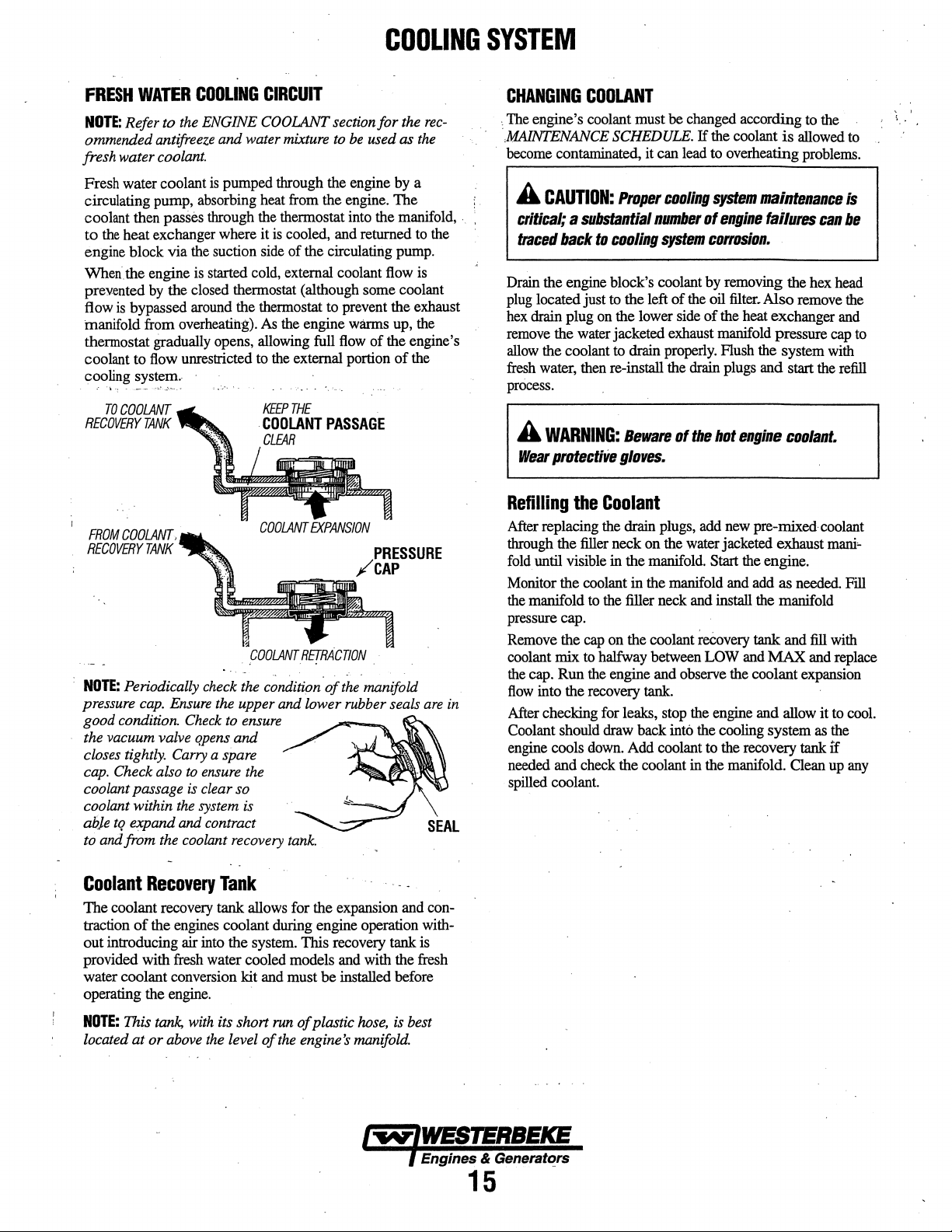
COOLING
SYSTEM
FRESH
NOTE:
ommended antifreeze
fresh water coolant.
Fresh water coolant
circulating pump, absorbing heat from the engine. The i .
coolant then passes through the thermostat into the manifold,
to
engine block via the suction side
When. the engine
prevented
flow
manifold from overheating).
thermostat gradually opens, allowing full
coolant to flow unrestricted to
cooling system.
RECOVERY
FROM
RECOVERY
NOTE:
pressure
good condition.
the vacuum valve qpens
closes
cap.
coolant passage is clear so
coolant within
abje
to
WATER
Refer to
the
heat exchanger where it is cooled, and returned
by
is
bypassed around the thermostat
..
•··
TO
COOLANT
TANK
COOLANT,
TANK
Periodically check
cap.
tightly.
Check also
tq
expand and contract
and
from
COOLING
the
ENGINE COOLANT section for the
is
is
started cold, external coolant flow
the closed thermostat (although some coolant
Ensure
the
Check
Carry
a spare
to
ensure
the
system is
the
coolant recovery
CIRCUIT
and
water mixture
pumped through the engine by a
As
the engine warms up, the
the
KEEP
.
COOLANT
CLEAR
.
pOOLANT
the
c;ndition.ofthe.manifold
upper
and
to
ensure
and
the
to
of
the circulating pump.
to
prevent the exhaust
flow
external portion
THE
PASSAGE
Rf!RACnON
lower rubber seals
tank.
be
used as
of
./PRESSURE
,_
the
to
is
the engine's
of
the
CAP
are
rec-
the
in
CHANGING
:The engine's coolant must be changed according to the
,MAINTENANCE
become contaminated, it can lead
A
critical; a substantial
traced
Drain the engine block's coolant by removing the hex head
plug
located just
hex
drain plug
remove
allow
fresh
process .
A
Wear
Refilling
After replacing the drain plugs, add
through the filler neck on the water jacketed exhaust
fold.
until visible in the manifold. Start the engine.
Monitor the coolant in the manifold and add as needed Fill
the manifold
pressure
Remove the
coolant
the
cap. Run the engine and observe the coolant expansion
flow
into the recovery tank.
After checking for leaks, stop the engine and allow it
Coolant should draw back into the cooling system as the
engine cools
needed and check the coolant in the manifold. Clean
spilled coolant
COOLANT
SCHEDULE.
CAUTION:
back
the water jacketed exhaust manifold pressure
the coolant
water, then re-install the drain plugs and start the refill
WARNING:
protectiVe
cap.
mix
Proper
to
c1111ling
to
the left
on
the lower side
to
drain properly. Flush the system with
Beware
glo'IIIS.
the
Coolant
to
the filler neck and install the manifold
cap
on the coolant reeovery tank and fill with
to halfway between LOW and MAX and replace
down.
Add coolant to the recovery tank
If
t:DOiing
number
of
system
of
the oil
of
of
the
the coolant
to
overheating problems.
system
engine
is
allowed
maintenance
failures
can
t:IJII'tJSi1111.
filter.
Also remove the
the heat exchanger and
bot
engine
new
c1111lant.
pre-mixed· coolant
cap
mani•
to
if
up
to
is
be
to
cool.
any
Coolant
The coolant recovery tank allows for the expansion and contraction
out introducing air into the system. This recovery tank is
provided with fresh water cooled models and with the fresh
water coolant conversion kit and must
operating the engine.
NOTE:
located at or
Recovery
of
the engines coolant during engine operation with-
This
tank.
above
with
Tank
its short
the
level
of
run
the
be
of
plastic
engine's
installed before
hose,
manifold.
is best
1-..IWESJERBEICE
l
Engines & Generatt?rs
15
Page 22

.
THERMOSTAT
A
thermostat,
engine,
continuously
engine
the
coolant
hole in
overheating).
gradually
checked,
gasket
and
Replacing
Remove
housing
gasket,
gasket
screws.
cap
Run the
are
there
controls
is
from
the
thennostat
opens.
cleaned,
the
as
shown.
apply
before
engine
no
leaks
located
the
flows
first
started,
flowing
As
the
The
or replaced easily.
the
Thermostat
cap
screws
a thin coat
pressing
and check for normal temperatures and that
COOLING
near the manifold at the front of
coolant temperature
through the closed cooling circuit When
the closed thermostat prevents
(some coolant
to
prevent the exhaust manifold
engine warms
thermostat is accessible
and disassemble the thermostat
When installing
of
sealant on both sides
it into place.
at the thermostat housing. ·
as
the coolant
is
by-passed (hrough a
up,
the thermostat
and
Carry
a spare thermostat
the
new thermostat and
D6'
not over-tighten the
the
from
can be
of
the
SYSTEM
RAW
WATER
NOTE:
Always install the strainer at or below the waterline
the
strainer will always be
A
clean
engine's cooling system.
strainer
in
the
glass
Perform
operation:
1. Close the
2.
Remove
3.
Clean the
4.
Replace
5.
Reassemble and install
6.
Open
7.
Run
NOTE:
Also follow the above
aground.
If
the engine temperature
normal reading, the cause
may
have been caught
raw
water
INTAKE
raw
water intake strainer is a vital component of the
when
making your
should
be
the
following maintenance after
raw
water
and
clean
glass.
the
washer
the
seacock. ·
the
engine and check
through
the cooling
STRAINER
self-priming.
Include a visual
periodic
clear.
seacock.
the
strainer
if
necessary.
the
strainer.
for
leaks.
procedure
gauge
ever
may
be that silt, leaves or
up
in
the
strainer,
system
inspection
engine check. The
every
100
filter.
after having
shows
a higher
slowing the
.
of
this
water
hours of
run
hard
than
grass
flow
of
so
.. . AIR
BLEED
FOR
.
COOLING
GASKET
USE
PETCOCK
PUSHING
SYSTEM
HI-
TACK
THERMOSTAT
ASSEMBLY
AIR
FROM
SEALANT
SENDOR
_
THE
.
S~INER
FILTER
--or,.,....
INCOMING
RAW
WATER
SEACOCK.
·
TYPICAL
RAW
WATER
(OWNER.lNSTALLED)
STRAINER
INSPECT
CLEAN
EVERY
toO
HOURS
AND
16
Page 23

RAW
WATER
The
raw water flow is created
impeller pump. This pump draws water directly
ocean, lake,
to
the water strainer. The raw water passes from
through the
exchanger tubes) where
water coolant.
water-injected exhaust elbow,
exhaust gasses. This mixture
driven through the stem tube and overboard.
HEAT
EXCHANGER
Cool
raw
exchanger.
the
heat
which is then pumped into the exhaust system
charged.
through the
NOTE:
Operating
that a heat exchanger cleaning
COOLING
or
river from a thru-hull opening through a hose
pump
to the heat exchanger (through the heat
The
raw water is then discharged into the
water
flows through the inner tubes
As
the engine coolant passes around these tubes,
of
the
internal engine
The
engine coolant (now cooled) flows
engine
in
CIRCUIT
by
a positive displacement
it
cools the engine's circulating fresh
mixing with,
of
exhaust gas and
is
conducted to the
and the circuit repeats itself.
silty and/or tropical waters may
be
peifonned more often
and
every 1000 hours.
COOLING
from
the
the
strainer
cooling the
raw
water is
of
the heat
raw
water
and
dis-
back
require
then
SYSTEM
RAW
WATER
The raw water
non-ferrous housing
has flexible blades which wipe against a curved
within the impeller housing, producing the
on
no account
always
be
(an impeller kit).
when lubricant (raw water) is not present during engine
operation.
are cautioned
start-up.
periodically for broken
MAINTENANCE
NOTE:
Should a failure occur
(seals
and bearings), it may
purchase
a
spare.
Changing
Close the raw water intake valve. Remove the
and, using an impeller
carefully pry the impeller out
impeller and gasket.
curved
cam
ing. When assembling, apply a
the impeller
PUMP
pump
is
a self-priming, rotary
and
a Neoprene impeller.
should
this
pump
be
run
a spare impeller and impeller cover
Raw
water pump impeller failures occur
Such
failures are not warrantable,
to
make
sure raw water flow is
The
raw water pump should
or
tom impeller blades.
SCHEDULE.
be
a new pump and
the
Raw
plate and push the impeller into
and
gasket.·Q~n
rebuild
Water
pullef1 screw drivers,
Move
the blades to conform
·.··'
be
inspected
with
the
pumps internal parts
more
cost efficient
the
original pump
Pump
Impeller
of
the pump. Install the
thin
coatjng
the
raw
water
pump
The
cam
pumping
dry.
There
gasket
and
operators
present
See
pump
or
pliers,
to
the
pumps hous-
of
lubricant to
intake
with a
impeller
plate
action.
should
aboard
at
to
as
cover
new
the
valve.
HEAT
EXCHANGER
CLEAN
OUT
BOTH
ENDS
.
NEW
ZINC
ANODE
A zinc anode,
circuit within the heat exchanger.
anode is to sacrifice itself to electrolysis action taking place
in the raw
of
electrolysis
condition
the anode
should
NOTE:
Electrolysis
and vessel location; not that
NOTE:
The
not
require
insulate
or
pencil, is located in the raw water cooling
water
cooling circuit, thereby reducing the effects
on
other components
of
the
zinc
anode
should
cleaned
be
carried
threads
or
replaced
on
board.
is
the result
of
the
zinc
sealant. Sealant should not
the
zinc from the metal
as
of
of
the
anodes
of
housing preventing electrolysis action
REPLACE . CLEAN
The
purpose
of
the system.
be
checked monthly and
required. Spare anodes
of
each particular installation
engine.
are
pipe threads and
be
used as
the
heat exchanger
on
the
zinc.
.
REUSE
the zinc
The
it
may
AND
do
.
A
CAUTION:
impeller,
cooling
they
circuit.
exchanger.
INSPECTION:
EACH
REPLACE
ANY
CHECK
BLADE
BY
THE
CRACKS.
"any
must
They
THE
BENDING
IMPELLER
LIGHTLY
PUMP
AND
IMPELLER
GLYCERIN.
INSPECT
AND
IMPELLER.
IF
THEY
OF
WEAR.
of
the
vanes
be
found
to
often
can
BASE
OF
VIGOROUSLY.
IF
THERE
ARE
GREASE
THE
0-RING
SHOW
THE
0-RING,
WITH
REPLACE
SIGNS
CHAMBER,
have
prevent
be
found
broken
off
blockage
in
the
heat
in
the
the
Engines & Generators
.
17
Page 24

ENGINE
LUBRICATING
OIL
ENGINE
1. Draining the Oil Sump. Discharge the used oil through
OIL
CHANGE
the
sump drain hose (attached to the front
while the engine is warm.
replace
securely.
the
hose
in
NOTE:
Thread size for the lube oil drain hose capped
Drain
the used oil completely,
its bracket, and replace the
of
the engine)
end
cap
end
is l/4NPT.
Always observe the
yellow/gray emulsion indicates the presence
the
oil. Although this condition is rare,
prompt attention to prevent serious damage. Call a
qualified mechanic
water present
exhaust system attached
of
raw water through
· exhaust, filling the engine. This problem is often caused
by
the absence
or
lack
of
maintenance.
2.
Replacing the Oil Filter.
filter; you
in
oil
to
be
NOTE:
filter
Place
filter
(Oil
cooling ability. Keep
oil filter
sealing gasket came
rubber sealing gasket remains sealed against the filter
bracket, gently remove it.
may
the
upper
from
it
into a container before removing it. This helps
lessen spillage. A
helpful
in
Do not punch this hole without first loosening
to
make certain
some
paper towels and a plastic
when
unscrewing
qr
any other fluid
as
it
used
oil
as
it
is removed. A
it
does require
should
water
be
present
in
the oil
can
be
the result
to
the engine and/or a siphoning
the
raw
water cooling circuit into the
of
an anti-siphon valve, its poor location
When
removing the used oil
find
it
helpful
and lower portion
small
removing
it
your
is removed·
off
and cleaner to punch a hole
of
automotive filter wrench should
the
old
oil filter.
can
be
removed!
it
to catch any
on
the
engine reduces the engine's
engine clean.) Inspect the old
to
inake sure that the rubber
with
the
the
old
old
oil
of
bag
oil
filter.
a fault in the
filter
around the .
left
in
of
the
to
in
If
water in
oil. Raw
drain the
the
the filter.
this
of
When installing the new oil filter element,
gasket's sealing surface
apply a thin coat
on the
new
oil filter. Screw the filter onto the
filter nipple
filter firmly
A
WARNING:
contaminants.
and
nails
discard
used
NOTE:
on
by
Avoid
thoroughly
clothing
oil
properly.
Generic filters
the oil filter bracket, and then
hand.
material standards or diameters
generic parts might
parts.
Immediately after
run
the engine
and
that
3.
Filling the Oil Sump.
cap
on
the
After refilling, run the engine for a few
checking
around
stop the engine.
oil
lube
dipstick; should the
to
there
are
top
of
the
oil pressure. Make sure there is
the
new oil filter
dipstick.·
on
the bracket free
of
clean engine oil to the
Used
engine
prolonged
using
or
rags
are
oil
contains
skin
soap
and
containing
not
recommended,
of
be
entirely different from genuine
an
oil filter
make
sure
the
oil pressure
no
oil leaks around
Add
new oil through
the engine
Then
Fill
engine .require additional oil.
or
through the side
or
from the oil drain system, and
check the quantity
to,
but
not over the
wipe
the
of
oil
and
rubber
threaded
tighten
harmful
contact.
water.
used
Clean
Launder
oil.
Discard
as the
important items
change
and oil
is
normal
the
new oil
the
oil
oil
moments
of
high
no
oil
while
leakage
with
mark
filter
gasket
oil
the
skin
or
on
fill,
filter.
filler
fill.
the
on the
LUBRICATION
OIL
PRESSURE-:--~ftllm~
SWtTCH
OIL
FILTER
DIAGRAM
...
~
Engines & Generators
18
REMOVE
TO
DRA1N
OIL
UP
THRU
USING
THE
Oil
THE
AN
BMM
•.
OR
HOSE.
(11/W)
PUMP
SOCKET
THE
WARMED
.
FOR
.
..
1/4"NPT
EXTENSION
Page 25

INSTALLATION
irhls popular
ter
from
~ngine
NOTE:
instructions
'tr9
install,
WES1ERBEKE's
4nstall
Contact
accessory
the
engine
to a more
room
bulkhead.
Refer
to
ENGINE
on
removing
'simply
remove
remote
this
kit with
your
the
WES1ERBEKE dealer
oil
is
used
to
relocate
convenient location
OIL
CHANGE
the
oil
filter.
the engine
oil filter kit
filter
facing
REMOTE
OIL
PN#040078
the
engine's
in
this
·
oil
filter and thread
as
shown.
down
as
for
more
information.
oil
such
as
·
manual
for
Always
illustrated.
FILTER
(OPTIONAL)
NOTE:
filan
incorrect
A
rectly.
on
pass
from
failure.
Immediately
Westerbeke
is not
installation
CAUTION:
If
valve
reaching
If
the
in
there
and
oil
the
the
It
flows
filter
is
check
responsible
of
the
Remote
is
vital
In
assembly
engine
no
oil
pressure
the
to
install
the
reverse
causing
bose
for
engine
failure
Oil
Filter.
the
oil
lines
direction,
will
prevent
an
Internal
reading,
the
engine
shutdown.
conrnec:tiolirs.
cor-
the
due
by-
oil
to
THE
OUT
CONNECTION
MUST
ATTACH
OIL
TO
ATTHE
FILTER.
CONNECTION
REMOTE
THE
HOSE
IN
APPLY A THIN
INSTALUNG
TIGHTEN
CONTACTS
COAT
OF
THIS
AN
THE
....._....._,,,~
CLEAN
KIT.
THREAD
AODITIONAL3/4
BASE.
{;;g;.:\.-E----Dt:l~nn:
OIL
TO
THE
TURN
THE
D-RING
KIT
ON,
THEN
AFTER
THE
O·RING
THE
IN
CONNECTION
MUST
ATTACH
CONNECTION
WHEN
HAND
OIL
ALTER.
TO
AT
THE
THE
HOSE
OUT
APPLY A THIN
GASKET
WHEN
CO.NTACTS
THE
COAT
OF
CLEAN
INSTALLING.
BASE,
TIGHTEN
OIL
TO
AFTER
IT
AN
THE
ALTER
THE
ALTER
ADDITIONAL·
Engines & Generators
..
19
Page 26

STARTER
MOTOR
DESCRIPTION
The starting system includes the battery, starter motor, solenoid,
and the start toggle
When the start
' current flows and energizes the starter's solenoid coil. The
energized coil
into the coil, and closes a set
to
reacli
the starter
to push
To prevent damage
pinion gear incorporates
is splined to the starter armature shaft The rotation
engine may speed
motor itself.
Once the start switch is released, the current flow ceases, stopping
the activation
contact with the battery-to-start cables by a coil spring, and the
flow
magnetic fields and
plunger is released,
from
TERMINALS
that
of
electricity is interrupted
its engagement
switch
becomes
starter
the
of
the solenoid.
switch.
on the instrument
an electromagnet, which pulls the plunger ·
of
contacts, which allow high current .
motor.
At the same time, the plunger also serves
pinion
to
mesh
to
the starter motor when the engine starts, the
an
over-running (one-way) clutch
rotation of
The
tO
the
starter
ceases
its
movement also pulls the starter drive
":'ith
the engine fly-wheel. .
panel
is depressed,
with the teeth
the
pinion but not the starter
plunger is pulled out of
the starter. This weakens the
its rotation. As the solenoid ·
SOLENOID
on
the
of
flywheel.
the running
which
g~
SOLENOID
IGNITION
TERMINAL
To
test
the
ignition
of
the
small
tel111IDal
Use
a
screwdriver,
ignition
terminal
the
solenoid.
If
tlie
starter cranks, the fault
If the
solenoid
motor
is
to
clicks
probably
circuit,
studs
don't
touch
the
positive
but nothing
faulty.
locate
and
is
the
ignition(s)
wired
blade,
battery
lies
with the ignition circuit
else
terminal (it
to
the
ignition
to
jump
from
connection
happens, the starter
tenniniu
the
n
is
circuit).
that
on
one
MOTOR
TYPICAL
STARTER
REFER
DIAGRAM
TROUBLESHOOTING
..
Prior to testing, make certain the batteries are
and that the starting system wiring connections (terminals) are
clean and tight Pay particular attention to the ground wire
Connections
To check the wiring, try cranking the starter for a few seconds,
never more than
The wires
resistance. Repair or replace any trouble spots.
Using
stud on the start solenoid and the engine block (ground).
If
you read 12 volts, the starter
MOTOR
TO
THE
WIRING
IN
THIS
MANUAL
-
..
on the engine block.
10
seconds at a
and
terminals looking
a multimeter, test the voltage between the positive terminal
time,
for
warm spots that indicate
is
faulty.
at
a full charge
then run your
hand
along
SOLENOID
IGNffiON
TERMINAL
. H nothing
,
Check
the
connections.
A
WARNING:
fly
when
space
gasoline.
at
all
battery
It
is
.jumping
is
free
happens the
isolation
also
switch
possible
There
terminals.
of
potentially
solenoid
that
will
be
Be
explosive
isn't getting current
and
inspect
the
the
solenoid
arching
is
and
certain.fhe
fumes,
~
wiring
defective.
sparks
engine
especially
will
Engln_es & Generators
20
Page 27
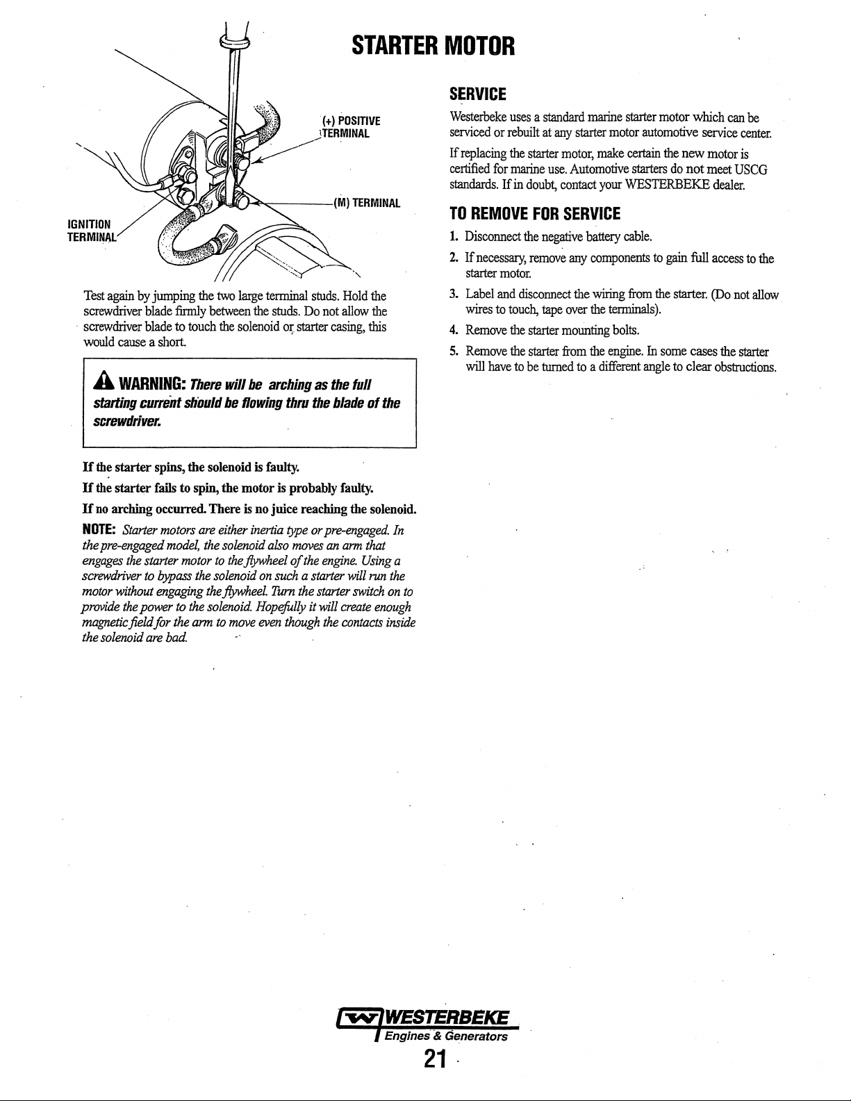
Test
again
screwdriver
·
screwdriver
would
cause
A
WARNING:
starting
screwdriver.
by
jumping
blade
blade
a short
cu"eilt
the
firmly
to
touch
There
s/iould
two
large
between
the
solenoid
will be
be
flowing
terminal
the
studs.
arching
01;
thru
studs.
Do
starter
as
the
STARTER
Hold
the
not
allow
the
casing,
this
the full
blade
of
the
MOTOR
SERVICE
Westerbeke
serviced
If
replacing
certified
standards.
TO
1.
Disconnect
2.
If
starter
3.
Label
wires
4.
Remove
5.
Remove
will
uses a standard
or
rebuilt
the
starter
for
marine
If
in
doubt,
REMOVE
necessary,
have
motor.
and
disconnect
to
touch,
the
the
to
FOR
the
remove
starter
starter
be
at
any
starter
motor,
use.
Automotive
contact
SERVICE
negative
any
the
tape
over
mounting
from
turned
to
marine
starter
motor
make
certain
starters
your
WESTERBEKE
battery
cable.
components
wiring
from
the
terminals).
bolts.
the
engine.
a
different
motor
which
automotive
the
new
do
not
to
gain
full
the
starter.
In
some
cases
angle
to
clear
can
be
service
center.
motor
is
meet
USCG
dealer.
access
to
(Do
not
the
starter
obstructions.
the
allow.
If
the starter
If
the starter
If
no
arching occurred. There
NOTE:
the
pre-engaged
engages
screwdriver
motor
provide
magnetic
the
solenoid
Starter
the
starter
to
without
the
power
field for
are
spins,
fails
motors
model,
bypass
engaging
bad.
the solenoid
to
spin,
are
the
motor
the
the
to
the
solenoid.
the
arm
is
faulty.
the motor is probably
is
no juice reaching the solenoid.
either
inertia
type
or
pre-engaged.
solenoid
to
solenoid
flywheel.
to
the
flywheel
move
also
moves
of
on
such
Turn
the
Hopefully
even
though
the
a
starter
starter
it
engine.
will
the
faulty.
an
arm
create
contacts
that
Using
will
switch
In
a
run
the
on
enough
inside
to
Engines & Generators
21.
Page 28

NOTE:
ments
be
below
is
ENGINE
WESTERBEKE
perfonned
provived
by a competent
to
assist
ADJUSTMENTS
recommends
the
that the following engiM
engine
mechanic.
mechanic.
The
information
adjust-
DRIVE
For
equipped with belt
front
guard is NOT installed for that purpose.) Operators are
advised that proper inspection, service, and maintenance
required.
Excessive drive belt tension can cause rapid wear
and reduce the service life
· A slack belt or the presence
slipping, resulting
The drive belt is properly adjusted
deflected
inch (12mm)
midpoint between
belt. A spare belt or belts should always be carried
Adjusting
1. Remove
2.
3.
4.
5.
6. Replace
7. Remove the guard
8. Replace
BELT
ADJUSTMENT
your safety, WES1ERBEKE generator models come
guards
that cover over the belt(s)
of
the engine. (''Out of sight- out of mind." The belt
of
the
fresh
water pump's bearing.
of
oil
on
the belt can cause belt
in
high operating temperatures.
if
no
less
than
as
the belt is depressed with the thumb at
the
A
WARNING:
drive
belt's
tension
Belt
Tension
the
belt guard.
Loosen
the
adjusting
With
the belt loose, inspect for
Pivot
the
alternator
Tighten
minutes and then shut
the
adjusting strap bolt
the
guard.
the
guard.
the belt
3/8 inch (lOmm) and
two pulleys on the longest span of
Never
attempt
while
strap
to
properly
Operate the generator for about 5
the
and
to
check
the
engine
bolt
and
the
wear,
tension
and
generator
recheck the belt tension.
no
or
is
in
operation.
alternator
cracks
the
drive
the
pivot belt.
down.
can
more than
adjust
and
of
be
on
pivot
belt.
on
the
is
the belt
the
the
board.
the
bolt.
frayed
1/2
edges.
TORQUING
After the initial break-in period (approximately 50 hours) and
every
re-torqued.
Tighten the cylinder head bolts according
shown. Make
Before applying the specified torque
114
to
procedure
illustration
Bolts #1, 2 and 3; (12mm socket)
Bolts
Rocketshaft Hold Down
Rocker Cover Hold Down
,
.FUEL
In
case
injectors checked and
injection service center. Poor fuel
loss
of
in
injector faults. Since
clean room
injector
Before removing the old injector, clean the area around the
base
of
falling
out easily
the injector side-to-side with the aid
free it, and then
The injector seats
washer.
replaced
installed.
INJECTOR
40
± 4
THE
CYUNDER
500
hours
thereafter, the cylinder head bolts should be
sure
the engine is cold
1/2
of a
tum
and then
according
to
#4, 5, 6, 7, 8, 9, 10
to
the right
the numbered sequence shown in
CYLINDER
INJECTORS
of
severe vibrations
overhauled
positive fuel pressure
fuel
envir<;mment,
as
a spare should a problem
the injector
down
and
This washer should be
with
TO
CYUNDER
ft-lb
(5.5 ± 0.5
to
help prevent any rust or
into the injector
is held in by carbon build-up or the like,
lift
it
out
in
the cylinder head on a copper sealing
a new washer
.
HEAD
kgf·m)
HEAD
BOLTS
to
when
to
the bolt, loosen it
apply
the torque. Follow this
14-22
and
11
(14mm socket)
Bolts-
HEAD
it is best
nGHTENING
12mm
socket
Cap
Nuts-
(IOmm socket) (snug)
BOLT
PATTERN
and
detonation noise, have the
by
an
authorized fuel
quality,
to
the
injectors must
hole.
remov.ed
when
contaminant's
injection pump
be
to
carry at least one extra
occur.
If
the injector will not lift
of
the socket wrench
with
the
new
injector is
TORQUE
the sequence
this is done.
ft-lb
(54-
(11
-
can
serviced in a
debris
fiom
the injector
16
result
work
the
61
ft-lb)
and
to
and
ft-lb)
Engines & Generators
22.
Page 29

ENGINE
ADJUSTMENTS
VALVE
NOTE:
engine's
BOLTS.
Pull
off
rocker shaft and valve assembly.
Remove the glow plugs from each
the engine to be easily rotated by hand to position each
cylinder for valve adjustment.
Valves are adjusted with
adjusted
stroke. Each cylinder
order (1-3-2 for WESTERBEKE's three cylinder engines).
CLEARANCE
Retorque
valves.
A
WARNING:
engine
is
cold.
firing
order
of
bolts
to
the
specified
off
the air breather pipe from the rocker cover, and
the
rocker cover bolts
is
at TDC
ADJUSTMENT
the
cylinder head bolts
See
TORQUING THE CYLINDER
Adjust
the
valve
clearance
Valves
are
the
(top
adjusted
engine.
Tighten
torque
and
the rocker cover to expose
the
piston in the cylinder being
dead center)
is
adjusted following the engine's
by
the
before
adjusting
of
the cylinders to enable
of
its compression
VALVE
CLEARANCE
before
adjusting
cylinder
cylinder
when
in
bead
the
the
HEAD
the•'
the
· ·
valves.
take
the
firing
#1
Adjust the valves in
Proceed
Rotate the crankshaft
rotation and adjust the next cylinder's valves
order.
the
Adjust each valve's clearance
(0.25mm) feeler gauge between the rocker arm and the
stem.
Re-install the glow plugs (use anti-seize compound on the
threads)
belts.
manual.
to
the next cylinder in the firing order.
Rotate the crankshaft another 240 degrees and adjust
next cylinders valves in the firing order.
Make sure
and
assemble the rocker cover and rocker cover
See the TIGHTENING TORQUE SCHEDULE in
cylinder for both intake and exhaust.
240 degrees in normal direction of
in
the firing
by
inserting a 0.010 inch
to
adjust all valves while the engine is cold.
valve
this
Valve
adjustment
crankshaft slowly
cylinder #1. Watch
piston
is
on it's intake stroke (the piston is moving down in
the cylinder). Continue
look for the intake
now starting it's compression stroke (the piston is moving
in
the
cylindt'r towards TDC).
Align the TDC mark on the crankshaft front pulley with the
timing marker on the front gear case cover when positioning
the
#1
Piston at TDC of it's compression stroke. Confirm
by
rotating the crankshaft approximately 20 degrees before
and after this point
should not move.
beginning
and
observe the operation
for
the intake valve to open indicating
valve
and
with
cylinder
to
rotate the crankshaft slowly and
to close. This indicates the piston
the two valves for the
#1.
of
#1
Rotate the
the valves
cylinder
for
the
up
this
is
Engines & Generators
23
Page 30

ENGINE
NOTE:
WESTERBEKE
ments be peiformed
is
below
provided
to
ADJUSTMENTS
recommends
by
a competent
assist
the
that
engine
mechanic.
the
following
mechanic.
engine
The
information
adjust-
Injection
If
your engine's fuel injection timing is not properly
the engine will not operate properly, and
start.
well-established fuel injection
follows:
NOTE:
fuel
do
this,
side
move
fully
1.
Remove
No.
2.
Remove
"0"
the
3. Reinstall only the delivery valve holder and reattach
high pressure fuel line
that
pointing away
line during the timing check.
Rotate
rotation
compression stroke.
Move
the electric
(as viewed from the
fuel
(no
crankshaft pulley should be directly aligned
indicator
If
the specified injection timing (15° BTDC) cannot
attained, adjust the timing by increasing or decreasing
thickness of shim material under the injection pump's
mounting
Changing the shim thickness by
changes
advance
To
retard
Refer
Pump
Have
the injection pump delivery rate checked
The
injection
delivery
unscrew
cover
to
the
fuel rack
to
the
left)
the
1 injector and
ring and remove the delivery valve spring
holder.
the
end that
the
engine's crankshaft in its normal direction of
to position piston
the
throttle lever to its
lift
line,
until the instant the fuel completely stops
drips).
At this instant, the
on
flange
the
the
the
to
your Generator's
Timing
pump
position
the fuel shut off solenoid and
expose
to
secure
high pressure fuel line
the
No. 1
would
from
pump. Slowly rotate the crankshaft
front),
the front of the gear case ±
to
change the injection timing point.
injection timing by approximately one
timing, decrease the shim thickness,
timing, increase the shim thickness,
Adjustment
shop.
Adjust the injection
fuel
rack
needs
when
peiforming
the
injection pump fuel
the
full fuel delivery position
it in this position
the
No. 1 fuel delivery valve
fuel
delivery valve holder over
to
the delivery
connect
the engine fuel will
No. 1 at
full
catching the fuel
15°
Parts
List for shim part
this
then
from
to
the fuel injector
the beginning of
open position
BTDC timing mark
.5
0.004 inch
(Spill
may
be
to
be
spill
remove
rack.
proceed.
between
holder.
flow
from
with
degrees.
(O.Olmm)
Timing)
adjusted,
difficult
by
in
the
timing.
Mar,).~.ally
(move
holder.
beneath
Attach
from
its
and
operation
clockwise
the
flowing
the
be
degree.
as
required.
as
required.
numbers.
to
a
as
full
To
the
the
the
it
so
is
this
No.
on
the
timing
the
1
To
INJECTION
HOUSIMG
STOP
WIRE---..~
BRACKET
CONTROL
IT
MARK
ON
PULLEY
PUMP
RACK
PLUNGER
19"
VALVE
SPRING
TAPPET
.ROLLER
24
TIMING
POINTER
TIMING
MARKS
Page 31

ENGINE
.
GLOWPWGS
The glow plugs are wired
When
PREHEAT
should
"click" on and the glow plug should begin to get
INSPECTION.
To
inspect
tions, then unscrew or unclamp each plug from tqe cylirider
bead. Thoroughly clean each plug's tip and threads
soft brush
oil"
deposits. While cleaning, examine the tip for
bum erosion;
TESTING·
An
accurate way to test glow plugs
..
one prod
Touch
to the body
other
plug will have a 1.0 - 1.5 ohm
used with the plug in or out
an multimeter to test the power
A
WARNING:
to
the
touch.
testing
the
·
through
is
pres$ed at
the
plug, remove the electrical
and
cleaning solution
if
it has eroded
to
-the
of
the glow
These
Be
careful
plugs.
too
glow plug's wire
plug,
of
glow
not
the preheat solenoid.
the
control panel tbis solenoid
tennina).
connec-
W,ith
to
remove
an
the c8rbon and
wear
much,
replace
is
with an ohmmeter.
as
shown. A good
resistance.
the
engine.
drain
(8
- 9 amps per plug).
plugs
will
to
burn
your
the
connection,.
This meth04
You
can also use
become
fingers
·plug.
very
when
and
~d
·glow
can:
ADJUSTMENTS
OIL
PRESSURE
To
test the
oil
pressure,
install
a mechanical
hot
a
the
hot
·
be
wanning
read
Oil
,
LOW
. A
ings. A rapid
failure.
ings,
the
oil
Pressure
OIL
gradual
For
see
the ENGINE
up
the
pressure
35-
551biin•
PRESSURE
loss
of
loss
additional
remove the oil pressure
oil
pressure gauge
engine,
set the engine speed at
gauge.
{2.5-
3.8
kg/em')
oil
pressure usually indicates a
of
oil
pressure indicates a
information
TRO_UBLESHOOTING
TESTING
on
low
OIL
PRESSURE
sender,
in
it's
place.
1800
·
worn
specific
oil pressure read-
.chart.
·
OIL
then
After
·
rpm
and
bear-
bearing
.
GALLERY
, .
:
·
GLOW
PLUGS
Re-install the plugs in the engine and
plugs should get
seconds.
circuit When
comp9und
A
than
GLOW
If
WARNING:
30
PLUG
very
hot (at the tetminal end) within 7 to
the plugs don't heat
reinstalling
on
the threads.
Do
not
seconds.
TIGHTENING
1.0-
1.5
TORQUE
M-KG
(7
up
quickly,
the
glow
plugs, use anti-seize
keep a glow.plug
-11
FT-LB)
test
them
check for a short
on
·
USING
A
·TEST
UGHT
agaiil.
for
mare
The
15
OIL
PRESSURE
The
oil
pressure
front
of the
l/8npt that
pressure
engine
gauge
operation.
engine.
will
allow
when
SWITCH
safety
shut-down
Adjacent
checking for proper
to the switch is an
for
the
connecting of a
switch
is
located at the
access
mechanical
oil
pressure
port
oil
during
/-.y-/WESTERBEKE
l
!Engines.
~
Generato.rs
25.
Page 32

ENGINE
TROUBLESHOOTING
ELECTRONIC
The
Electronic Control Unit
aspects
programmed
ECU
injection
If
engine
operating
must
DC
NOTE:
requires
software
ECU
of
is
monnted
an
operating fault
and
be
breaker on the control panel
manufacturer:
CONTROLLER
the
drive engines operation.
and the programming
on
the
pump
and
controls
occurs,
illuminate
fault
re-set
to
Engine
ECU
software
and
communication cable
the
has
been investigated
re-start the
shutdown (check engine
Woodward,
PROBLEM
LOW
OIL
PRESSURE
HIGH
COOLANT
TEMPERATURE
BATTERY
(HIGH
VOLTAGE
DC/LOW
DC)
ENGINE
(ECU)
SHUTDOWN/CHECK
monitors
can
The
not
and
unit
be
altered.
engine block just adjacent
the
The
injection
ECU
pumps
will
shutdown
Check Engine LED.
and
corrected,
engine.
for
proper troubleshooting.
To
OFF,
is
Inc./
Aerospace.
re-set the
then
ON.
LED
available
illuminated)
from
CHECK
PROBABLE
1.
Oil
level
low/oil
leak.
2.
Lack
of
oil
pressure.
3.
AGround
4.
Faulty
5.
Faulty
1.
Check
2.
Sea
3.
Check
4.
Faulty
5.
Ground
6.
Faulty
1.
Check
2.
Check
3.
Check
4.
tau
connection.
oil
pressure
control
system
water
pump.
water
temperature
connection.
control
alternator
charge
battery
tty
battery.
switch.
module.
coolant
pump
drive
switch.
module
drive
voltage.
connections.
controls all
is
factory
The
to
the
fuel
operation.
the
When
the
The
ECU
ECU,
turn
the
This
ECU
the
ENGINE
SHUTDOWN
ENGINE/LED
CAUSE
level.
belt.
(ECU).
belt..
ENGINE
IS
ILLUMINATED
1.
2.
3.
4.
5.
1.
2.
3.
4.
5.
6.
1.
2.
3.
4.
LIGHT
ELECTRONIC
PN.8404-1021
WOODARD
VERIFICATION/REMEDY
Check
oil
level,
add
oil
Test
oil
pressure.
inspect
oil
Check
ground
Check
sensor/replace.
Inspect
all
Add
coolant.
Inspect
impeller/pump/replace.
Adjust
belt
Check
sensor/replace.
Check
ground
Check
plug
Adjust
tension/replace
Check
excitation.
Check + and -cables
Load
test
If
OK,
filter,
inspect
connection.
the
plug
in
Check
for
tension,
battery.
replace
circuit.
connections/replace
Replace/repair
CONTROLLER
AEROSPACE
.
and
repair
leak.s.
test
oil
pressure
sendor,
oil
pump.
connections/replace
leaks.
belt.
if
worn.
from
battery
ECU.
ECU.
alternator.
to
engine.
GENERATOR
Overs
peed
Underspeed
HIGH
EXHAUST
(External
No
No
Software
diagnosis
Note: Refer
Fault)
shutdown
LED
needed
FREQUENCY
to
to
the
Table
1.
2.
3.
4.
5.
1.
2.
3.
4
5.
of
Contents
•.
Check
engine
speed.
Check
fuel
supply.
Amperage
Crank
(underspeed
Generator
(underspeed
Check
Faulty
Ground
Sea
Faulty
load.
cycle
with
Shut-down.
sea
water
exhaust
connection.
water
pump.
fire
suppression
for
addztzohal
fault)
fault)
no
start.
flow.
temperature
. .
switch.
system.
T/WliBLESHOOTING pages m
Engine11_
26
~
Generators
1.
Check
speed
setting.
2.
Inspect
filters/replace
3.
Check + and -cables
4.
Check
cause
for
5.
Check
MPU
(voltage
(Check
MPU-
1.
Inspect
thru
hull
as
needed.
2.
Test/replace.
3.
Check
ground
4.
Inspect
impeller/replace.
5.
By-pass
system/check.
thzs
manual .
no
coil
resistance)
fitting,
circuit.
filters.
Test
from
battery
start.
cranking.
hose
and
fuel
pump
to
engine.
strainer.
operation.
Correct
Page 33

ENGINE
The following troubleshooting chart describes certain
problems relating to engine service, the probable causes
these problems, and the recommendations to overcome
these problems.If the engine shuts down
is illuminated), refer to
manual.
ECU
Troubleshooting Chart in this
(Check Engine/LED
TROUBLESHOOTING
NOTE:
The
of
engines
ampere manual reset circuit breaker. The preheat solenoid
mounted on the same bracket.
electrical system
is
protected by a 20-
is
PROBlEM
Engine
can
Starting
battery
Engine
slows
Engine
overheats
shuts
down.
Preheat
switch
No
panel
indications
electrical
Start
switch
No
starter
not
be
stopped.
not
being.
and
stops.
and
depressed
fuel
pump.
depressed
activation.
or
1.
Faulty
DC
1.
DC
charge
2.
Alternator
1.
Fuel
starvation.
2.
Contaminated
3.
Exhaust
restriction.
1.
Antifreeze
1.
Battery
switch
2.
20
Amp
breaker
3.
Emergency
4.
7.5
amp
fuse
5.
Blocking
6.
K2
Relay
1.
K1
Relay
2.
Faulty
starter
3.
Low
DC
battery
4.
Poor/loose
PROBABlE
alternator.
circuit
drive.
fuel.
coolant
off.
tripped.
stop
switch
faulty.
diode
open.
faulty.
faulty.
solenoid.
charge.
battery
faulty.
not
circulating.
open.
cable
connection.
CAUSE
1.
Remove
alternator.
1.
Perform
alternator
2.
Check
drive
output,
1.
Check
fuel
2.
Check
filters
3.
Check
for
build
up
1.
Loss
of
2.
Air
in
system.
Check
recovery
3.
Thermostat
1.
Check
switch.
2.
Check/re-set
3.
Check/close
4.
Check/test
5.
Test
diode.
6.
Check/test
1.
Check/test
2.
Test
solenoid.
3.
Check
battery
4.
Check
connections.
VERIFICATION/REMEDY
Exc/R
connection
DC
voltage
section
belt
tension,
excitation
supply,
for
contaminates/water.
blockage,
in
water
injected
coolant.
Check
Expel
circuit.
stuck
20
amp
switch.
fuse.
K2
Relay.
K1
Relay.
charge
off
alternator.
check
of
charge
in
this
manual.
loose
connections,
voltage
present
filters,
tank
vent.
collapsed
air.
closed.
exhaust
exhaust
system
for
Add
coolant
Check/test/replace.
breaker.
state.
at
Exo/R
elbow.
leak.
Repair
circuit.
hose,
as
needed.
See
DC
voltage
terminal.
carbon
TROUBLESHOOTING
If
the gauge reading
by the gauge when the instrument panel
is
to check for 12 volts DC between the ignition (B+)
step
and the Negative (B-) terminals
Assuming that there is
instrument panel energized and perform the following steps:
1.
Disconnect the sender wire at the gauge and see
gauge reads zero, which
situation.
2.
Remove the wire attached to the sender on the engine
and ground it to the engine. The gauge in the panel
should register full scale, which
situation. DC voltage at the oil and temperature sender
to ground when the engine
(10-
11
VDC) and will fall as the oil pressure rises and
coolant rises. This DC voltage will generally stabilize in
- 7VDC range depending on what your engines
the 5
normal oil pressure and coolant temperature are.
is
other than what is normally indicated
of
the gauge.
12
volts
as
required, leave the
is
the normal reading for this
is
is
first started will be high
WATER
is
energized, the first
normal for this
Engines & Generators
TEMPERATURE
if
the
27
AND
OIL
PRESSURE
If
both
of
the above gauge tests are positive, the gauge is
OK
undoubtedly
conductor from the sender to the gauge or with the sender.
If
either
of
probably defective and should be replaced.
Assuming the gauge is
sender to the sender terminal at the gauge for continuity.
Check that the engine block is connected to the ground.
Some starters have isolated ground terminals and
battery is connected to the starter (both plus and minus
terminals), the ground side will not necessarily be connected
to the block.
and the problem lies either with the
the above gauge tests are negative, the gauge is
GAUGES
OK, check the conductor from the
if
the
Page 34

ENGINE
TROUBLESHOOTING
PROBLEM
Generator
but
does
not
Starting
looses
Engine
Low
Smokey
battery
charge.
shuts
oil
pressure.
exhaust.
engine
start.
down.
cranks
1.
Faulty
preheat
2.
Faulty
fuel
3.
Fuel
supply.
4.
Fuel
filter(s)
1.
Faulty
battery.
2.
Oil
pressure
3.
DC
alternator
1.
Loss
of
oil.
2.
Oil
pressure
3.
Contaminated
1.
Blue
smoke.
2.
White
smoke.
3.
Black
smoke.
PROBABLE
circuit.
pump.
contaminated.
switch
stuck,
faults.
switch.
oil.
CAUSE
closed
contacts.
1.
TesVcheck
2.
Test
fuel
3.
Check
fuel
4.
Inspect
1.
Load
test
2.
Panel/fuel
3.
Check
alternator
1.
Locate
leak
2.
TesVreplace.
3.
Change
1.
Crankcase
2.
Incorrect
1.
Engine
running
2.
Faulty
injector.
1.
Lack
of
air,
2.
Incorrect
3.
Valves
need
4.
Low
compression.
VERIFICATION/REMEDY
circuit
components.
pump
operation.
ON.
all
filters.
battery.
pump
and
oil,
locate
overfilled.
grade
cold,
check
fuel
grade.
adjustment.
activated
charge
correct.
of
after
rate.
source
of
oil.
thermostat
intake/air
shutdown.
contaminates.
stuck
filter.
open.
Engine
starts,
then
shutsdown.
(stays
running
Preheat
Engine
horsepower.
depresed).
has
loss
runs
with
of
1.
1.
Safety
MAP
sensor
shutdown
(manifold
switch
absolute
faulty.
pressure).
1.
Check
safety
exhaust)
1.
TesVreplace.
shutdown
switch
(oil,
coolant,
Eng_ines
28
&
Generatof'~
Page 35

ALTERNATOR
TESTING
DESCRIPTION
The charging system consists
engine
regulator, an
cuit
breaker
the use.of integrated circuits (IC's) the electronic voltage
ulator
back of
and a battery with connecting cables. Because
is
very
the
alternator. ·
110
B+OUTPUT
To
114
DC
compact and is mounted internally or on
RED
starter
motor
PURPLE
of
an
alternator with a voltage
wiring
harness,
50
AMP
ALTERNATOR
,
a mounted DC
TROUBLESHOOTING
A
WARNING:
hot.
Do
not
This troubleshooting section is
exists with the charging circuit or with the alternator.
determined
best
to
have a qualified technician check it
The alternator charging circuit charges the starting battery
and the service
or
a battery selector switch is usually mounted in the circuit
to isolate the batteries
along with the
starting battery
service battery
A
WARNING:
that
everyone
sheaves
and
A failed
touch
that
the alternator or voltage regulator is bad,
battery.
service
but
not
charging
Before
is
clear
belts
alternator
until
the
alternator
An
isolator with a diode, a solenoid,
so
the service battery is not discharged
battery.
If
the service
circuit
and
starting
of
moving
during
test
can
bas
to
determine
the
alternator
battery,
the problem is
not with
the
engine
parts!
Keep
procedures.
become
cooled
if
out.
is
the
make
very
down.
a problem
If
it
charging the
in
alternator.
certain
away
from
cir-
the
is
it
reg-
is
the
of
Testing
1.
2.
3.
the
Alternator
Start the Engine.
After
a
few
minutes of running measure the starting
tery voltage at the battery
on
DC
set
The
the alternator is working.
If
the
after
problem exists
a.
Turn
Ensure
connections
A
switch
b.
,If
ensure
c:.
Thrn
d.
Check the battery voltage.
condition
volts.
voltage should be increasing
TESnNG
BArnRY
(ENGINE
the
starting
engine
off
the
that
THE
STARTING
·ALTERNATOR
RUNNING}
battery
is
with
engine.
the battery terminals
are
CADnON:
charging
a battery selector switch is.in the charging circuit,
circuit,
when
the
that
it
is
on the ignition switch, but
the
reading should
texminals
toward
Thrn
to
voltage remains around
started and
the alternator or
tight and clean.
To
never
engine
on the correct
run
Inspect all
avoid
damage
shut
is
mnnlng!
If
your battery
be
for
wiring
and
off the
setting.
do
12
MULTtMETER
using
a multi-meter
14
volts.
Step
4.
12
volts
a few
minutes,
the
charging circuit.
and connections.
the engine ground
to
the
battery
engine
battery
not
start
the
engine.
is
in
good
to
.13
volts.
If
bat-
it is,
a
A
WARNING:
-.
.D.C..and_jJ_C.J:Jn:u.lt$JLI'JtfJ1lmJJJJix.IHI.JD.get/ulr
applications.
Isolate
before
made
DC
perfonning
without
Always
and
proper
AC
Molt/meters
disconnect
converter.s
DC
testing.
knowledge
and
and
No
DC
sllore
shut
AC
of
AC
Circuits:
power
down
tests
should
clrt:lllts.
ln.
marine
cords,
generators
be
En!:Jines
TESnNG
BATTERY
& Generators
29
THE
STARnNG
•
ENGINE
OFF
,STARTING
BA11ERY
Page 36

e.
Now
check
the
voltage between the alternator output
terminal
voltage
tery,
age will be
between the alternator and the
connections
cuit.
(B+)
and ground.
at
the alternator should
or
if
an
isolator is
zero.
If
-look
not, a problem exists in the circuit
for
ALTERNATOR
If
the circuit
be
in
the circuit the alternator volt-
battery.
an
opening in the charging cir-
is
good, the
the same as the bat-
Check all the
TESTING
Alternator
4.
Check the voltage of the service
should have a
engine is running.
battery charging circuit Troubleshoot the service
charging circuit
the solenoid,
is
Working
voltage
by
isolator,
battery.
between
If
not,
checking the wiring and connections,
battery switch
there
13
and
14
is
a problem in the service
and
This battery
volts
when
battery
the battery
the
itself.
.
STARTING
·
f.
Start the engine again. Check the voltage between the
alternator output and ground .
The voltage reading for a properly operating alternator
should be between 13.5
tor
is
able service shop.
NOTE:
a voltmeter
present at
showed only battery voltage at
If
12
the
wiring
BAlTERY
TESTING
BATTERY·
(ENGINE
over-
THE
STARTING
ALTERNATOR
RUNNING)
or
under-charging, have it repaired at a reli-
Before renwving
to
ensure that
the
EXC temzinal if
volts
are
not
presenJ
lookiJzg
for breaks and poor connections.
and
14.5 volts.
the
alternator for
12
volts DC excitation is
the
previous test
the
B output tenninal.
at
the
EXC
tennina~
..J_L-4t=---'·
If
your alterna-
repair;
use
trace
ENGINE
GROUND
A
charging
Megger).
ALTERNATOR
When
and
and the alternator
wire
wiring
Turn
Depending on when
. brushes may need
send it to a service
MULTIMETER
CAUTION:
.
circuit
You
can
When
do
not
damage
INSPECTiON
rebuilding the
inspected. The
brush. Make
connections that connect
the rotor pulle:?by
engine.
housing
terminal
certaip
the
replacing.
shop
SERVICE
BAmRY
TESTING
BATTERY
pedorming
use a high
the
alternator
The alternator should be cleaned
can be wiped off with a s?lvent
studs should
those studs are
to
the wiring harness.
hand.
It should turn smoothly.
alternator was last
If
the alternator
for
testing and overhaul.
THE
(ENGINE
tests
on
voltage
diodes.
be
cleaned
tight.
se~ced,
SERVICE
the
alternator
tester
Also clean
1s
at
all
RUNNING)
(i.e.
With
a
the
the
·
suspect,
30
Page 37

DC
CIRCUITJBAnERY
BAnERY
The
generator's
reviewing the DC
The engine's DC wiring
circuits: start, run and
The engine
shown
when troubleshooting or
system
A
charging
switch
battery
·
when
CHARGING
DC
Circuit functions to start, operate and stop the
engine. The circuit
Wiring
has
a
12
volt
on
the Wiring
or
the engine.
CAUTION:
circut,
while
switch,
working
Diagrams.
To
avoid
never
the
engine
however,
on
the
stop.
is
best understood by .
Diagram
is
designed with three simple basic
DC
when
shut
is
engine's
and Wiring Schematic.
electrical control circuit that is
Refer
to
these diagrams
servicing the DC electrical
damage
to
to
off
the
engine
running.
avoid
Shut
electrical
electrical
the
battery
off
circuit.
battery
the
engine
shorts
SPECIFICATIONS
The
minimum recommended
the engine's t2Atolt DC control circuit is 600-900 (CCA).
capaCity
of
the battery used in
TESTING
If
the starting battery is not being charged. Verity
output from the alternator's
·there is excitation voltage at the alternator's ''R'' terminal.
Check battery cable connections
the engine and at the
BATTERY
Review the manufacturer's recommendations and then
establish a systematic maintenance schedule for your
engine's starting batteries and house batteries.
• Check the electrolyte level and specific gravity with a
• Use only distilled water to bring electrolytes to a
• Make certain that
• Keep your batteries clean and
THE
CIRCUIT
B+
starting battery.
MAINTENANCE
hydrometer.
level.
battery
cable connections are clean and
tight to the battery posts (and
De
voltage
output terminal. Check that
DC + and DC
to
your engine).
free
of
corrosion.
-both
proper
at
Engines & Genef'lltors
31
Page 38

:
I
[
..
_
..
_
..
_____
..
_
..
____
NT
1 4 T ,
_,_,_,_,
..
,_
___
,
fREOUEIICY
POWER
LIN£
AC
FOR
SPEED
TBI-&
TO
ENGINE
CONTROLS
CONNECTED
8
8
PIN
PIN
ECU
GOHz
I.
NOTES:
~
IN
.•
.
I . · I
! , \
!
DSl
EG
COIINECTION.
TBI·8
5.5,1.6
TO
SYSTEM
CONNECTED
8
HARIIESS,GENSET
JUMPER
SUPPRESSION
•
Pill
riR£
56209
REMOVE
50Ht
2.
•
I 1
I i
AMP
EG
DSL
20
OSl
EG
DSl
tG
5.5.8·15
CONN
EG
BLOCK
Pill
PNl
Pill
BOX
INSTR
PNL
TERMINAl
JUIIP[R,
KARIIESS,GEN
HARNESS.
HARNESS.
HARNESS,GEN
-
•
•
•
56240
56261
5&ZZ3
•15223
a
•56224 •
a
•
20A CIRCUIT
BREAK£R·I2VDC
'
I
I
'
..~
........
-'9'---,
__
,
I""U-,
l
:
STOP
L:_j
:
..J
..
_
..
-
TCM
..
SWI
..
..
_
..
_,_,_
..
E
-
OtC')
~a
oZ
CD
Ot
~5!
-~>
,.._
SPEED
GOVERNOR
ElECTRONIC
_
,....
IR£0»
~Ut
WHT
120
CJ$_YUfJ!8J.~_f_RjJL-,.
SENSOR
llilifiilfirl.
WH-T/\'tt.
WHTIQLK
118
118
MAP
SENSOR
IJ'HTIBLIJ~o
WHfiiLK~
120
120
!1!Ll!!:!..Il!!::;tt
==
~
Ljl
_21_ng ___ -
j9
..
,_
: HOUR
I
1.._
:
~i
:g:
~'
I
··---··-··-··-··~
"
: :
~
IN£
..
CHECK
U
ENG
; ; I
·-··--
7.5A
rusE
SA
FUSE
LIGHT
I
1
!lED
If
mmu
89X
PANEL
114
..
_
..
~
_,_
..
87654321
-··-
-,AAAAAAA~
,--·-··
..
'
-
..
-
..
-
..
-
..
··-
r
I I f J 1
!
~~
l
~I
lllUL/IIfD
,----------·------------1-EJ
~
ff21ia
'
0
~"\.IIGORG
5'
~
IQ
R<>
~
Ql
0
l1l
~
iii
PER
PLUG
ONE
CYLINDER
G~OW
(A)
N
SWITCH
EXHAUST
TEMPERATURE
Page 39

~------
........
l
OPTIONAL.-
:
BsAJ,w:
20A
CIRCUITj
BREAKER
E·STOP I
$WITCH
TIH
1
._
r:
...
r
I
·-------.--
WIRING
SCHEMATIC
#056225
PREHEAT
SOLENOID
r--,
I
STARTER!
SOLENOID
1
1
...
__
......
TBZ•II
BATTERY
12
VDC
GLOWPLUGS
ONE
STARTER
ALTERNATOR
B
R
TBH
PER
CYL.
FUEL
PUMP
l.SA
fUSE
T81·2
DIODE
5&282
TIZ·5
lBZ.Z
WATER
T82·•
-------·-··-··-··-··-
KI·START
II&
TEMP.
OIL PRESS. SUDER
REUI
$ENDER
TBI·I
TBI-lt
--,
NOTES:
I.
ECU
PIN
8
tOHt
50Hz
2.
FIRE
RENOV£
•51289 •
•
SI2Z3 • HARNESS,GEN
•5&224
•
58240 • HARNESS,
•
58211 • HARNESS,
•15223 •
CONTROLS
Ptll 8
CONNECTED
PIN 8 CONNECTED
SUPPRESSION
JUMPER
HARNUS,GENS£T
•
HAANESS,GEN
INSTil
PNl
JUMPER,
TERMINAL
ENGINE
TO
TBI-6. I
TO
TB
1·8
STST£M
·CONNECTIOII.
5.5.7.6
Pill
.[G
DSL
Pill
5.5.8·15
PilL
EG
801
CONN
BLOCK
SP£ED
EG
£G
DSL
EG
DSL
20
AMP
OSt
rOll
AC
ll
NE
POWER
fR£0U£NCY
:
.
L
..
....:!~!!!~!!..!~~-~~C!.'~:.
______________________ , _____
HOUR
~ET~~---··-··-··J
:
Page 40

REMOTE
START/STOP
PANEL
WIRING
DIAGRAM
#56321
1/.\~~~~~~8
r··-··-··-··-··-··-
I
. o I
j
.
I o 8
Q
.....
c:
....
·.-··
114
·-
BLK
i >
~
>
~
•
L----+----...
·-··-·
'
a:
:
-··-··-··-··-··-··-··-··l
114
VEL/RED
PREHEAT
SWITCH
.---+--
-
RELEASE
STARTER
LIGHT
Q
.....
c:
co
""
:
I:
STOP
SWITCH
-·--------··-··-··-··-··-··-··-··-··
EXTENSION HARNESS
lSFf,
8 PJN,
PJN,
PN#36236
PN#36235
30Ff, 8
114
RED
START
SWITCH
..........
··-··-··-··-··-··-··--·--:
l"ffiiiV'lWESISRBEKII
.I
Engines &
~nerstors
34
Page 41

SPECIFICATIONS
•
5.5/5.0KW
EG
GENERATOR
Engine
Type
ASpiration
Governor
Combustion
Bore & Stroke
5.5Kw
Piston
5.5Kw
Firing
Direction
Maximum
Compression
Dimensions
Weight
Fuel
5.5Kw
Inclination
Compression
Valve
Valve
Engine
Valve
(Engine
Injector
Engine
5.5Kw
General
Oil
Sump
(not
Operating
(engine
Oil
Chamber
Displacement
Order
of
Rotation
Torque
Ratio
Consumption
Pressure
liming
Seat
Angle
Speed
Clearance
Cold)
Pressure
liming
Filter
Capacity
mcluding
Oil
Pressure
hot)
Grade
ENGINE
TUNE-UP
(Spill)
SPECIFICATIONS
Diesel,
water-cooled,
mechanism
Naturally
Centrifugal
Swirl
2.99 x 2.76
58.00
1 .
3.
Clockwise,
27
fHb
21:1
Height:
Width:
Length:
3361bs
0.54
Continuous
Temporary
SPECIFICATIONS
398
psi
(Limit
47.2
Intake
Intake
Exhaust
Exhaust
Intake
Exhaust
1800
1500
Intake
1968 ± 142
15°
BTOC±
LUBRICATION
Pressure
Full
flow,
3.2
filter)
U.S.
35 -55
API
Specification
better.
four-cycle,
(9.2
aspirated
type
type
inches
cubic
inches
2
when
(3.4
kg-m)
19.9
inches
16.0
inches
27.2
inches
(152.4
US
gph
14°
25°
(28
kg/em')
of
Difference
psi
(3.0
Opens
Closes
Opens
Closes
45°
45°
rpm
60
rpm
50
and
Exhaust
psi
.5
fed
system
paper
Qts
(3.031iters)
psi
(2.5 -3.8
SAE
10W-40
three-cylinder,
vertical
in-line
Hp
at
1800
(76 x 70
(0.952
liters)
viewed
from
at
1800
(505.5
(406.4
mm)
(690.9
kgs)
(2.011ph)
kg/em')
19°
Hertz
Hertz
(BCDB:
(not
to
at
between
BTDC
51°
ABOC
51 • BBDC
19°
ATDC
0.098
(140 ± 10
approximate
14")
exceed
280
inches
kg/em')
SYSTEM
by
geared
element,
spin--on
kg/em')
CF,
CF-4,
or
15W-40
fresh
overhead
rpm
maximum)
mm)
the
front
rpm
mm)
mm)
30
min.)
rpm
limit
cylinders)
(0.25
pump
type
CG-4,
CH-4,
valve
mm)
Cl-4
or
General
Fuel
Fuel
Injection
Pump
Fuel
Injection
timing)
Filter
Combustion)
Battery
Capacity
Aid
Cranking
Charging
Regulator
Temperature
Water
Water
Flow,
rpm
Capacity
water)
liming
Amps
Pump
(Spill
Nozzle
Fuel
Air
cleaner
Air
Row
(Engine
Starting
Battery
Starter
Starting
DC
DC
VoHage
General
Operating
Fresh
Raw
at3600
System
(fresh
AC
Single
Phase
VoHage -Single
Voltage
Frequency
Rating
.5.5Kw
Generator
Ambient
Recommendations
Electromagnetic
Interference
Generator
Air
Requirements
Phase
Regulation:
Regulation:
(Volts/Amps)
Compartment
Temperature
level
Cooling
FUEL
SYSTEM
Open
flow,
self
No. 2 diesel
In-line
15° ± 5o
Throttle
Cartridge
Plastic
25.6
30.2
ELECTRICAL
12-Volt,
600 -900
12-Volt,
Glow
175-200
51
Capacitor
COOLING
Fresh
controlled
1700
Centrifugal
6.5 • 7.0
before
4.0
GENERATOR
Brushless,
Self-exciting,
excitation.
design.
120
220
±5%
.5
Hertz
60
50
120°F
NOTE:
to
maintain
temperatures
Exceeds
telephones
CE
175 -200
(60
oil
plunger
BTDC
type
type
intake
cfm
(0.7
cfm
(0.6
SYSTEM
(·)
ne_gative
Cold
reduction
plugs,
sheathed
Amps
Amp
IC
13-14
SYSTEM
water-cooled
-1oo· F (77"-
type,
US
gpm
discharging
qts
(3.791iters)
(Single
four-pole,
capacitor
Pre-lubricated,
120
volts,
Volts -60
Volts • 50
no
load
to
(6%)
Hertz
(1800
Hertz
(1500
(50°C)
Forced
generator
requirements
and
(Certified
Europe)
cfm
Hertz)
at
1800
silencer -cleaner
maximum
below
bleeding -self
(cetane
rating
(Bosch
type)
(Before
Top
cmm)
BCD,
cmm)
BCD
ground
Cranking
Amps
type
(engine
cold)
volts
DC
block,
sa•
C)
metal
impeller,
(24.6 -22.5
into
exhaust
Phase)
revolving
saturated
single
phase
Hertz
Hertz.
full
load.
no
load
to
full
rpm)
120
rpm)
220
ventilation
should
compartment
120°F
for
standard
televisions.
requirements
(4.95 • 5.66
rpm
priming
of
45
or
higher)
Dead
Center)
BCDA,
BCDB
5.5
Kw
(CCA)
(in
generator)
thermostatically-
belt-driven
lpm)
(measured
elbow).
field.
field
single-bearing
load.
Volts/45.8
Volts/21.7
most
be
(50"C)
marine
cmm)
Amps
Amps
provided
radio
Meets
NOTE:
Increase
air
I.....,.I§I'ERBEKE
t
Engines & Generators
35
supply
15%
for
50
Hertz
operation
@1500
rpm
Page 42

GENERATOR
INFORMATION
USE
OF
ELECTRIC
The power required to start
more
than
is required to keep it running after it
Some motors require much more current to start them than
- others. Split-phase
under similar circumstances, than other types.
monly used on easy-starting loads, such
machines; or where
started, such
7 times
avoided, whenever possible, if the electric motor is
ven
by
motors require from 2
to run. The current required to start
load connected to
compressor, for example,
motor
In
general,
to
medium
MOTOR
*NOTE:
more for
fo.r
this
rnaile-in
Because
motors is
be
damaged if it can bring the motor
seconds.
off
all
on
the
Required
Run
the
generator's capacity, and finally loaded to its
indicted on
should be checked periodically
the generating plant
voltmeter or ampere meter is not installed
and load, check it with a portable meter and amp probe.
NOTE:
contains AC equipment
the
that
vide
one
panel.
as
as
much current
a small generator. Capacitor and repulsion-induction
to
which
the
cwrent
starting
SIZE
(HP)
116
1/4
1/3
1/2
3/4
1
In
the
above
some
is
that
Zcfrger
-
the
heavy
required·
If
difficulty
other electrical loads and, if possible, reduce the load
electric
Operating
generator
the
When
the
generator's AC terminal block be
120
volt AC hot
This
will
MOTORS
an
electric motor is considerably
is
started.
(AC)
motors require more current to start,
They
are com-
as
washing
loads
are applied after the motor is
small power
it.
An
no
load
required
loads
table
small motors
the
hardest starting types (split-phase)
tools.
Because
to
start
as
to
to
4 times
electric motor connected
is
will
AMPS
(AMPERES)
as
much current
any
will
require more current than a
connected.
to
start
115-
be
approximately
FOR
RUNNING
3.2
4.6
5.2
7.2
10.2
13
the
maximum Amps
than
for larger
they
run, their use should be
motor varies with the
Volt
require 5
to
to
start
to
an air
motors
connected
as
follows:
AMPS
FOR
STARTING
(AMPERES)
6.4
to
22.4*
9.2to
32.2*
10.4
to
72.8*
14.4
to
29.2*
20.4
to
40.8*
26to52
for
Starting
ones.
The
are
sizes.
surge
of
current needed for starting
for
only an instant, the generator will not
up
motor.
to speed
is
experienced in starting motors, turn
in
a few
Speed
first
with
no
load applied, then at half the
full .capacity
generator's data plate. The output voltage
to
ensure proper operation of
and
the appliances it supplies.
vessel
in
which
of
120
leg
ensure
good motor starting
the
generator
volts
only,
for
the
vessel's distribution
to
it
configured
If
an AC
monitor voltage
is
installed
is
recommended
to
response
from
generator.
to
be dri-
as
reason
not
as
pro-
the
is
Generator
Frequency is a direct result
indicated by the following:
• When the generator
output frequency is
• When the generator
output frequency is
Therefore, to change the generator's frequency, the generator's drive engine's speed must be changed. A reconfiguration
of the AC output connections
sary.
Generator
• Maintaining reasonable cleanliness is important.
Connections
become corroded, and insulation surfaces
ducting
allowed
cause excessive heating and reduced life of windings.
• For unusually severe conditions,
leum-base coatings, should be sprayed or brushed over
surfaces
suggested are Daubert Chemical Co.
410" and Ashland "Tectyle 506" or equivalent.
•
In
inspected for
of overheated terminals and
• The drive discs on single bearing generators should be .
checked periodically
and for
should not
accelerate cracking. The bolts which fasten the drive disc
to
8,
ners
• The rear armature bearing is lubricated and sealed;
maintenance is required. However,
noisy or rough-sounding, have it replaced.
• Examine bearing at periodic intervals.
of shaft should be detected
motion is
shaft
Repair
rub
The
and
..
decal
·~generator
·
The$6
Frequency
Adjustment
of
engine/generator speed,
is
run at
1800
RPM, the
60
Hertz.
is
run
at
1500
RPM, the AC voltage
50
Hertz.
at
the
generator is also neces-
AC
Maintenance
of
terminal boards
if
salts, dust, engine exhaust, carbon, etc. are
to build
to
addition
any
the
generator shaft must be hardened steel SAE grade
identified
of the head.
of
bearing socket outside bearing has occurred.
n;tust be made quickly or major components
an4
cause major damage to generator.
generator's
frequency
is
on
voltage
up.
Clogged ventilation openings may
reduce rusting and corrosion. '!ypical materials
to
periodic cleaning, the generator should be
(a}
tightness of all connections, (b) evidence
if
possible for tightness of screws .
evidence of incipient cracking failure. Discs
be
allowed
by
deteGtable,
rating
the
inside
end
that
to
6 radial marks, one at each
bearings
data
plate
of
the
of
the
includes
diagrams
and
rectifiers may
may start con-
thin
rust-inhibiting petro-
"Non-Rust AC-
{c)
loose or damaged wires.
become rusty because rust may .
of
the 6 cor-
if
the
bearing becomes
No
side movement
when
force is applied.
are
wearing or wear on
gives
the
voltage,rurrent,
generator.
louvered
the
are
also
AC
voltage
shown
An
AC
wiring
cover
at
the
connections.
on
these
as
voltage
all
no
if
side
will
pages.
I...,.,IWESTERBEKE
)
Engines_.&
Genei1#0TS
36
Page 43

BC
GENERATOR
NOTE:
WESTERBEKE
and adjustments
recornrrzends
be
peiformed by a
SINGLE
that
the
qut:di.fied
PHASE
following generator tests
technician.
DESCRIPTION
The
BC
generator
requires
AC
stator
is
induces
larger
of
windings
capacitor(s)
in
a
drawn
equipment.
120
or
SPECIFICATIONS
ratings.
and
affixed
end. A diagram
provided
output.
windings
started,
current
current
the
stator.
steady
off
volt
230
volt
The
frequency
to
only
residual
a current
in
quickly
voltage
the
AC
the
on
is
the
driving
The
stator
and
the
magnetism
in
the
in
the
exciter
the
four
reaches
and
a regulated energy
At
the
same
in
the
generator's
The generator is a single-phase, re-connectable
two-wire
AC
two-wire
section of
generator's data plate gives
rating
inside
of the louvered cover at
of
the
the
decal.
a brushless, self-excited generator
force
of
the
engine
to
produce
houses
two
sets of windings;
exciter windings.
in
the
four rotating
stator
which
then generates
windings.
rotating poles and
the
saturation point of
field
time,
this
regulated
stator windings
AC
terminals
at
60
at
of
the
various
hertz, or
50
generator.
115
hertz.
Refer
this
manual for generator
AC
voltage connections
When
This
mutual build
in
the
is
then
which
to
operate
volt
to
the
voltage, current
An
AC
the
the
poles
exciter ·
the
maintained
field
produces
can
_then
AC
AC
two-wire
the
wiring
the
generator
generator
an
decal
which
an
main
even
up
be
is
is
Circuit
A circuit breaker
WES1ERBEKE generators. This circuit breaker
automatically disconnect generator power
electrical overload. The circuit breaker can be manually
shut
power is coming into the boat.
NOTE:
add-on
WESTERBEKE
60Hz - 5.0 KW Circuit Breaker Part Number 42705
50
Breaker
is
installed
off
when
servicing the generator to ensure that
This
circuit breaker is available
kit for earlier model generators; contact your
dealer.
Hz
- 4.0 KW Circuit Breaker Part Number 42704
on
all single phase
as a WES'IERBEKE
in
will
case of
an
no
GENERATOR
INTERNAL
WIRING
A.
ROTATING
WITH
DIODES.
B.
MAIN
STATOR
C.
EXCITER
SCHEMATIC
FJELD/AUXILIARY
WINDINGS.
WINDINGS
AND
CAPACITOR(S).
r-
i l
I
I
I - - .
: t
WINDINGS
AC
TERMINALBLOCK
--
---
--
--- ---
CAPA~~TOR
t t
..
~-
~.:-:-
-~
CA~A"ITOR
t
Engines & Generatqrs
37
-------------
DUAl
---.J
EXCITER
CIRCUIT
-.
Page 44

SINGLE
1.
2.
3.
EXCITER
Remove
generator,
the
capacitor(s).
Start
the
five
minutes
generator
current
correct. Refer
connection
Referring
check
voltage
meter.
no-load voltage
the
proceed.
from
appliances).
the
across
Make
voltage output
NOTE:
and
adjustments be performed by a qualified technician.
NO-LOAD
the
louvered metal plate, at
covering
generator
is
change.
to
generator's no-load voltage
the
and
so
the engine can warm
operating without
the
generator (that
Make sure
to
the
DC
the
AC
load connections diagram
the
neutral lead and
sure you record
is
115
is
higher or lower than specified,
VOLTAGE
AC
terminal connections
allow it to run for approximately
any
is,
the
engine's speed (Hertz)
Wiring Diagram
this
reading. The generator's
-
124
volts
BC
GENERATOR
WESTERBEKE recommends that the following generator tests
SINGLE
PHASE
ADJUSTMENT
the
back of
up.
equipment drawing
shut off
by
the
hot lead
at
60.5 -61.5
the
and
Make sure
all
electrical
for
the
ECU
below,
measuring
with
Hertz.
@)
the
is
the
AC
P8
a volt
If
A
WARNING:
age
adjustment
capacitor
any
wiring
addition,
ment
while
lingers
to
5. There
6. · H the generator's no-load
are
minal,
#7, #8, and #9.
low,
then disconnect
nect the plug with
tor's no-load voltage is high,
numbered plug
number.
tenninal may be
because the voltage
numbered plug is
or the voltage-needs
bered
p1ug
Genefator Troubleshooting Guide).
Do
not
attempt
while
the
generator
can
produce
can
produce a severe
attempting
the
generator
be
caught
tln·ee
Note that the
is connected, refer to the WESTERBEKE
a
400·500
to
make a no-load
Is
in
the
generator's
plugs grouped for the right capacitor
If
the
the
lower numbered plug and
the
next
and
connect
plug
any
one
of'the three
voltage
needs
already
connected
to
be lowered
to
make a no-load
Is
operating.
volt
charge.
electrical
shock.
voltage
operating
could
cause
rotor.
generator's no-load
higher
number.
then
disconnect the higher
the
plug
presently connected
cannot be adjusted
to
be
increased and the
and
with
plugs
to
the
the
If
the next
available.
right
lowest
volt·
The
Touching
In
adjust-
your
ter-
voltage
con-
the
genera-
lower
to
this
highest
terminal,
num-
BC
is
115V/50Hz
firl
l:dxJ
N
4. Shut off the
(60
Hertz #6, or
capacitor(s).
A
WARNING:
handling
tially
power
as
_lethal·
charge
source.
L1
230V/50Hz
generator.
50
Capacitors
they
store·
ll
I•
®
• •
L1
N_
Make sure the correct Hertz lead
Hertz #5)
electricity
even
is
plugged into the ·
must
when
disconnected
be
and
GROUNDED
INSIDE
GENERATOR
discharged
can
pack a poten-
from
TO
OF
THE
CASE
before
their
THE
A
WARNING:
.
the
unused
with
each
housing.
I
BC
Make
leads
are
in
other
or
In
contact
GENERATOR
120V/60Hz
certain
place
and
with
BACK
END
the
insulating
are
NOT
in
the
generator's
NOTE:
THE
SHOWN
DEMONSTRATION
THESE
BE
SHOWN
#7
CONNECTED
CONNECTIONS
MAD£
covers
on
contact
WIRE
IS
AS
OF
HOW
CAN
A
NOTE:
Simply
insulated
any·excess
cross
(plastic
electricity.
the
capacitor's
handle)
two
screwdriver.
tenninals
This
will
with
an
discharge
EtJglnes
38
& Generl!tors
SINGLE
EXCITER
CIRCUIT
Page 45

BC
GENERATOR
NOTE:
WESTER./JEKE
and
Cu:ljustnients
DUAL
EXCITER
These generators
adjustment connectors at
connectors available
for
Hertz
selection,
connectors, #7, #8,
adjustment.
When
making Hertz-change or no-load voltage adjusunents
proceed
1.
2. Select
as
Shut
the generator down.
the
capacitor
RPM. The three other connectors at each capacitor, #7,
#8,
and
produced
group
can
will
increase or decrease approximately 8-10
between
achieve the prescribed no-load
CIRCUIT
have
60
and
follows:
appropriate Hertz connection
#60,
60
#9,
will
have
by the
generator.
be
plugged into each capacitor. No-load voltage
connectors used in any pair combination to
_.------..._
DUAL
MODEL
dual Hertz and no-load voltage
each capacitor. There are
for
each capacitor.
Hertz
or
#9,
are for no-load voltage
Hertz,
1800
an
effect on the no-load voltage
One connector from each
EXCITER
Two
50
Hertz,
RPM
or
volta~e
CIRCUIT
be performed by a qualified
connectors
and
three
to
plug into each
#50
Hertz,
AC
as
illustrated.
r_ecommends
five
are
1500
volts
SINGLE
that
the
PHASE
following generator tests
technician.
NOTE:
Simply
cross
the
capacitor's
insulated (plastic handle)
any
excess
electricity.
Shore
Power
If
the installer connects shore power to the vessel's AC cir-
cuit,
this
Switch. Set the transfer switch shown in the diagrams to the
OFF position. This switch prevents simultaneous connection
of
shore power to generator output.
A
CAUTION:
utility
shore
at
the
same
covered
liflity
to
120Volt/60
·-:Ganeratot
~._N~Gt"~
Connections
must
be
done by means
Damage
power
time.
under
the
make
sure
Hertz
screwdriver.
to
and
generator
This
type
warranty;
all
AC
Three
NOTE: Diagram
wfre.120·V'olt l'fstiim from the gener-ator,
with
'th.,..
...
w1re.120•Vott boat system.
two
terminals with
This will discharge
of
the Shore
the
generator
power
of
generator
it
Is
the
installer's
connections
Wire
show•
are
Configuration
connections for a
Power
can
result
are
connected
damage
responsi·
correct.
two-
an
Transfer
if
is
not
When
changing Hertz produced by
reference
connection
terminal blocks must
be
must
frame ground
volts,
A
handling
tial/y
power
the
DC
change.
produced.
be
The
changed for 50 Hertz
wire
50 Hertz
to
WARNING:
as
they
lethal
charge
source.
Wiring
Hertz plug connection at
230
store
GENERATOR
Diagram for
The
AC output connections
be
selected for
(#5)
must be moved
volts,
50
Hertz.
Capacitors
must
electricity
even
when
disconnected
BACK
the
the
ECU
the
voltage and Hertz
the
or60
Hertz (#6).
when
changing from
be
diScharged
and
can
pack a poten·
•
230
Volt/50
L1
END
generator,
P8
on
the
to
capacitor
The
115
z
..
::!
"
before
from
their
1-.viWESTERBEKE
·l
Engines.~
Generators
39
Hertz
GENERATOR
GROUND
lL1
SHORE
220V
N
•
POWER
50HZ
Two
~
;:
..
N)
Wire
Configuration_
GENERATOR/SHORE
SWITCH
- SHORE
- GROUND
Shlp-to•Shcn'* Switch
PH
32008
PN32009
PN32010
PN32133
SHIP'S
LOAD
Page 46

BC
GENERATOR
NOTE:
WESTERBEKE recommends that the following generator tests
and adjustments be performed by a qualified technician.
SINGLE
PHASE
INTEGRAL
The
Integral Controller (I. C.) is an encapsulated, solid-state
unit that supplies a DC charging voltage to the generator's
starting battery while the generator is opening.
Charging
(;barging
A separate group
btidge rectifier which converts the
I.1C. unit. The I.C. unit senses the needs
ahd
suppli~s
that the
low), check the charging circuit and it's components as
d~cribed
deahliness and tightness including the ground before
irtg
.the
t(On:
produce a low charging rate. This charging rate will rise as
{fie generator is operated.
Tlhe Integral Controller is mounted inside the generator hous-
i~g
in the 12:00 position.
CONTROLLER
CONTROLLER
Voltage: 13.0 - 14.0 volts
Amperage: 0 - 10-
of
stator windings supplies
a
DC
charge when
I.
C.
unit is faulty (that is,
in
the following steps. Check all connections for
I.
C.
unit.
When the generator is first started, the L
EARLY
BCD
(I.C.)
amps
AC
current to supply the
cine
is needed. If you suspect
if
the battery's charge is
and
BCDA.MODELS
DC
DC
of
the starting battery
INTEGRAL
AC
voltage
C.
unit will
to
replac-
Testing
1. Bridge Rectifier
a
2.
3. Testing
If
the
the
Battery
Normal
engine is operating at
two
illustrated).
AC
Normal
DC) is measured across the two
bridge rectifier; that is + and
DC voltage running from the bridge rectifier
(approximate):
AC
Lift the two
measure, the resistance between these two leads with an
ohmmeter.
should exist between these two leads and the ground or
the main
the rectifier fails
AC
voltage running
AC
connections
voltage running to the bridge rectifier (approximate):
No-load
Full-load
No-load
Full-load
winding: 0.14
A. Set the meter
B. Connect the positive ( +) lead from the meter to point
Taking the negative(-) lead, momentarily touch points #1,
#3,
C. Remove the positive ( +) lead from point
#3. the
D. Leaving the negative (-) lead on point
E,
rectifier
off
DC
voltage running out
off
AC
It
AC
the
Bridge
. . . - ' . ' .
and
#5. There should
meter.
negative(-) lead
Ohm
each point
the positive ( +) lead.
value.
Place the
lead on point #3.
value. Reverse these connections and the meter should
register
no
as
Charging
1800 rpm)
on
the bridge rectifier. (As
the
generator
off
the
generator
the
generator
off
the
generator
ohm
wire leads off the bridge rectifier and
should measure 0.14.ohm. No continuity
stator windings
Rectifier (meter
on
Ohms scale.
to
it. Momentarily touch
meter should register an arbitrary Ohm value at
Circuit
to
the rectifier (while the
is
measured across the
16.0 volts
17.5 volts
of
the rectifier (in volts
DC
connections
-.
..
be
no Ohm value registered
17.0 volts
18.5 volts
used-
AC
AC
FLUKE
#4
of
the
DC
DC
multimeter).
and connect the
point~
#1,
it touches.
#4,
touch point #5 with
The
positive(+)
The
Ohm
value.
any
of
it
is defective.
meter should register
lead on point
meter again should register no Ohm
the
previous tests B
#1
and the negative(-)
no
through
#4.
#2,
on
the
#2
and
Ohm
E, replace
+
-
GND
BLACK
YELLOW
GROUND
GENERATOR
TO
CASE
BRIDGE
RECTIFIER
AC
En_gfnes & Generators
40
.#4.
BRIDGE
RECTIFIER
IF
THE
BRIDGE
RECTIFIER
AIVY
TESTS,
REPLACED
OF'
FAILS
THE
IT
SHOULD
ABOVE
·
BE
Page 47

DESCRIPTION.
-
Oiiee~ttie
_
engiile,made
mOUiited
positiotfin
frOm
line
STEP
UPPER
AS
EXISTING
~lly~Pass
pJiun~l#.';fh'e-~
to
ifte
\Yater
~.1htWilter
in a
COftVeilient
relation
~heater
without
1:
UN-BOLT
ANO
LOWER
ONE
ASSEMBLY.
BY..PASS
to
to
lhe
any
loops
AND
THERMOSTAT
REMOVE
RXnJRE.
the
engmedm
whiclnmglit trap
REMOVE.
~on
~i.e
locanen
ertgitle
THE
so
mE ·
HOUSINGS
i$
ifiStaUed
·coolant
·h~tet
shollld
either
in
a high or
that-the
run.·m•
eon:necting-hoses
a
~hably
air.
on
the
can~
be _
low
direct
-
·
INSTALLAnON
Follow
lower
the
Heater
The
· to connect
the
steps
1hetmostat
e:idslirtg
By-Pass
hoSe
spuds
to
as
housing~
by
..
pass
as shown itt STEP
on the
518"
lD.
illustrated
'l1iiS
fixttfre
as
He"ater
hose,_
below.
Remove
will
allow
access
showll in STEP
2.
By-Pass
use the hose
are
adapters:
for
the
1.
3/8"
upper
to
remove
Install
I.D.
and
tbe
bose,
STEP
SEALING
WA1ER
ANO
PARTSUSnNO
HEAtER
BY~PASS
-
SEALING
THERMOsTAT
HOUSING
HOSE
THERMOSTAT
HOUSINC
0-RING
(2)
LOWER
GASKET
ADAPTERs
(2)
GASKET
2:
ATTACH
O~RINGS
HEATER
ASSEMBLE
PN
042743:
PN
036937
PN
03701&
PN
302391
PN
03&956
THE
TWO
TO
tHE
8}(-PASS
AS
ILLUSTRATE!).
THERMOSTAT
HOUSING
.
STEP
HEATER
4:
HOSES
HEATER
INSTALL
TO
BY--PASS.
STEP
3:
HOUSING
GASKEr
'TUII:DIIineTIIIT
GASKET·
iHE
7WO
THE
NEW
RE~NSrAU
ASSEMBLY
HOUSING
REMOVE
THE
THERMOSTAT
USING
THE
AND
NEW
DISCARD
41
Page 48

DOMESTIC
HOT
WATER
HEATER
CONNECTIONS
WATER
Once the Heater By-Pass
engine, plumbing
made
mounted in a convenient location either
position in relation
from the
line
A
TO
HEATER
to the water heater.
heater
to
without
WA1FR
HEATER
CONNECTION
any
TANK
PY-PASS
INSJAUATIONS·.
~onnectionis
of
the erigine.antifreeze
The
water
to
tbe
engine
so
the engine
loops which
WATER
can
might
HOSEADAPrm
41302391
HOSE
HEATER
installed
coolant
heater
should
in
a
high
that
the
connecting hoses
run
in
a reasonably direct
trap
air.
- 3/ll"
TO
5/ll"
THERMOSTAT
ASSEMBlY
ClAMPS
CONNECTIONS
on
or
the
can
be
low
.
be
HEATER
When
expansion tank
convenient'location
NOTE:
ABOVE
the
water
heater
is
The expansion tank replaces the stanilard plastic
recovery tank and
and
fillpoint.
As
shown
in
the
fitting
at
connection B
.rise continuously
air to rise
.Remove .the plastic
.:
needed.
manifold
to
the tank
Remove
and
plug
REMOTE
(REPLACES
RECOVERY
EXPANSION!
COOLANT
1ANKJ
EXPANSION
PN0241TI
KiT
THE
ENGINE
is
located
above the engine, a remote
required. Install the expansion tank in a
above
the
water
heater.
wiU
now
serve as the systems
illustration, a
on
the
to
the
expansion
and
be
expeUed).
coolant
its
the
recovery tank fhat is no longer
attachment
opening
TANK
'
single
hose
water
heater. That hose must
tank. (This will allow
fitting
from
'with a 1/8npt plug.
is
the
check
teed
exhaust .
into the
point
any
Using
the
Heater
By-Pass
as
illusltirted
increase
HOT
HEATEfl
FILLING
Fill
the engine's cooling system with antifreeze thru the
pressure cap operating
engine and monitor the coolant until
noted.
antifreeze to the coolant recovery tank (mark).
m1tifreeze
fully functional.
below.
the
hose
size
WATER
THE
COOLING
Fill the manifold and install
circuit with its hot water heater should now
connection, install
Use
the
hose
from
adapters
3/W'
to
5/8".
HEATER
(PN302391)
BELOW
!ENGINE
SYSTEM
on
the exhaust manifold. Start the
good
circulation is
the
pressure cap. Add
hoses A and
to
CONNECTIONS
HEATER
BY-PASS
The
engine's
be
B
FROM
HEATER
FILLING
Ftll the
on
pressure
expansion
and
expelled.
stable
the pressure
engine
~k
engine's
the
engine's
cap
monitor
and
coolant
THE
add
HOT
WATER
HEATER
ABOVE
COOLANT
cooling
water
and
continue
tank.
Fill
the
the
coolant
coolant
good
circtilation
cap
on
the
level,
ENGINE
SYSTEM
system
jacketed
filling
t3Dk
level
to
maintain
is
remote
it
is
now
at
exhaust
the
to
about
hi
the
felt
tank.
done
(REMOTE
the.
pressure
manifold
system
~
frilL
remote
this level.
at
both
heater
When
at
the
remote
TANK)
cap
opening
Install the
at
the
remote
Start
the engine
tank. As air is
Once
the level is
hoses, install
checking
the
expansion
.
Engines & Generators
42
Page 49

POWER
TAKE
OFF
SYSTEMS
POWER
A
backend.
engine
THE
PRODUCE
1800
FOR
THE
TAKE·
power
take
This
for a variety
BC
GENERATOR
9.0
RPM.
THIS
GENERATOR
POWER
TAKE-OFF.
OFF
ADAPTER
off
adapter
adapter
HP.
(APPROXIMATE)
HORSEPOWER
AC
allows
of
hydraulic
MODELS
OUTPUT
can
be
attached
access
to
and
electrical
IN
THIS
MANUAL
AT A CONTINUOUS
CAN
BE
OR
UTILIZED
FOR
EQUIPMENT
to
the
full
EITHER
FROM
the
generator
power
accessories.
.
of
the
POWER
KIT4#34786
TAKE
OFF
Contact
information.
your
WESTERBEKE
DISTRIBUTOR
for
additional
Engines & Generators
43
Page 50

LAY-UP
&
RECOMMISSIONING
GENERAL
Many
owners
rely
on
their
boatyards to prepare their craft,
including engines
off-season or for
to
accomplish
The
procedures
lay-up
own
you
if
have
local
check list
These procedures
during a lay-up and
maintenance
If
your
provide assistance.
Propeller
The transmission
be
opened
out of
the
water or
storage
apply
period of time.
recommended for
1bis
antifreeze, depending
Should
amount
and
cooling
in
the
severe strain on the propeller shaft or coupling or
the
boat
is taken out or put in the water.
has
shaft
not in
Fresh
A
solution
mixture.
actually
to
small boats that are hauled out
use,
Water
50-50
solution
solution may
to
more
from
Operate
mixture
system.
Lubrication
With
the
engine
sump.
Remove
with
new
oil.
ENGINE
oil
oil
LUBRICATING
changing
pressure and
A
CAUTION:
in
the
sump
combustion
chemicals
internal
parts.
and
generators,
long
periods
lay-up preparation themselves.
which
follow
and
recommissioning,
others
do
the
procedures.
should
afford your engine protection
also
help
needs of your engine.
any
questions
servicing
Shaft
and
up and
the
cradle.
been
unless
they
Cooling
of
use
make sure
antifreeze
the
engine
the
of
the
Now
regarding lay-up procedures, call
dealer;
Coupling
propeller half couplings should always
bolts
moved
The
flexibility
bent by these strains. This does not
have been dry for a considerable
· ·
Circuit
antifreeze
in the coolant system at all times.
require
a higher concentration
on
the area's winter climate. Check the
the
antifreeze protection is adequate.
be needed, drain an appropriate
block and
engine
antifreeze
recheck
for lay-up during
of inactivity. Others prefer
will allow you
or you may use them
familiarize you with the
he ~ be more than willing to
[Propulsion
removed when the boat is hauled
from land to water, and during
[Propulsion
and
distilled water is
add
to ensure a complete circulation
concentration throughout the
the
antifreeze solution's
System
warm,
drain
all
the
and
replace
the oil filter and
Use
the
correct
grade
of
OIL
pages in this manual for the
procedure.
over
deposits
which
Run the engine and check for proper
make
sure there are no leaks.
Do
not
leavfl
the
the
iay-up
period.
combine
can
reduce
to
produce
the
life of
to
perform your
Engine]
of
the boat often puts a
In
some cases, the
of
the water when
a more concentrated
engine oil from
fill
oil. Refer to the
enginet
old
Lubficating
harmful
your
the
both, while
Engine]
of
strength.
the
the sump
engine
oil
and
englnet
as
oil
oil
Fuel
System
Top
off your fuel tanks with unleaded
or
higher.
stabilizer should be added. Change the element
gasoline/water separator and clean
and
make certain there are no leaks. Clean
a
fuel
Fuel
System
Top
off your fuel tanks with
additives should be
mix
With
Additives. such
be·
should
condition the
used are compatible with the
separator used in the system. Change the element in your
primary fuel filter/water separator clean the separator
sediment
Change the fuel filter elements
fuel system,
5 - 10 minutes to make sure no air is left
for
system. Check for any leaks that may have been created
the fuel system during this servicing, correcting
needed. Operating the engine for 5 - 10 minutes will help
allow movement
equipment on
Raw
Water
Close the through-hull seacock. Remove the raw water intake
hose from the seacock.
gallon bucket
check the zinc anode found in the primary heat exchanger on
the engine
any
zinc debris from inside the
zinc anode is located. Clean
Start the engine and allow the raw water pump to
fresh water through the system. When the bucket
stop the engine and refill
solution slightly stronger
protection in your area
Start the engine and allow all
through the
the engine. This antifreeze mixture should protect the raw
water circuit from freezing during the winter lay-up,
as
providing corrosion protection.
Remove the impeller from your raw water pump
antifreeze mixture will accompany it,
Examine the impeller.
a cover gasket. Do not replace the impeller (into the pump)
until recommissioning, but replace
[Gasoline]
A fuel conditioner such
g~line
as
Sta-Bil gasoline
the
metal bowl. Re-install
of
in
up
any spilled
89
octane
your
[Diesel]
No.
2D diesel fuel. Fuel
added
prior
to
topping
the
fuel being
as
added at this time to control bacteria growth and
fuel.
bowl
as
needed. Start the engine and allow it to run
the
Cooling
of
and clean or replace it as required, and also clean
raw water system. Once the bucket
added
and fuel still in the tank.
Bio-bor and Diesel Kleen+ Cetane Boost
Care should be taken that the additives
primary
on
the engine and bleed
of
the treated fuel through the injection
engine.
CircuH
Place
the end
clean fresh
water.
heat,_exchanger
the
raw water strainer.
the
bucket with
than
needed for winter
of
this
Acquire a replacement,
off
to
ensure
fuel filter/water
the
in
the
fuel
them
as
of
this hose into a
Before starting the engine,
where the
draw
the
is
empty~
an
antifreeze
freeze
mixture to
so
the
cover and
be
drawn
is
empty,
as
well
(some
catch it in a bucket).
if
needed, and
gasket.
they
in
five
stop
l"ffV'lWESTERBEKE
l Engines & Generators
44
Page 51

LAY·UP
&
RECOMMISSIONING
Starter
Lubrication and
if
battery connections
the
connections removed from the starter.
Cylinder
If
WESTERBEKE
access
the cylinder walls.
revolutions and
If
to
the
Intake
Clean
cloth lightly
block
through-hull exhaust.port, Make a note
to
Cylinder
Remove the
spray
coat the intake,
Reinstall the
NOTE:
and
tions.
attach
Motor
cleaning
access
to
the starter permits its easy removal. Make sure the
starter.
Take
care
Lubrication
you
anticipate a
recommends removal
to
the
cylinders.
re-install the glow plugs.
your
engine
does
be
removed.
injectors
and
Be
return
Manifold
the
filter screen in the flame arrester, and place a clean
soaked in lube oil around the flame arrester
any
opening.
start-up!
Lubrication
flame
fogging
gap
Re-install
oil
into
valves
flame
At
re-commissioning,
them.
Rotate
the
the
high
tension
of
the starter drive pinion is advisable,
are
shut off before attempting
in
properly replacing any electrical
[Diesel]
long
lay-up period (12 months
Squirt some Marvel Mystery Oill into
Rotate
the engine crankshaft
not
have glow plugs, the injectors will have
sure
to have replacement sealing washers for
fuel line
as
needed.
[Gasoline]
Also
place an oil-soaked cloth in the
[Gasoline]
arrester and clean. Operate the engine
the intake stalling the engine. This will
and cylinders with a protectiqg
arrester.
remove
the
engine
by
spark
plugs
and
Zeds.
Batteries
If
batteries
make
to prevent them
. batteries will not
subjected
batteries·and store
environment
A
highly-explosive
arcing
smoke
serviced.
ftl
Transmission
Check or change
off
the
coating.
additional
are to
sure that
they
from
to
severe environmental conditions, remove the
WARNING:
or
a lighted
or
allow
Shut
Pfll.ftlnt
grime
coupling
electrical
and,
grease
and
Check
that
information,
[Propulsion
be
left on board during the lay-up period,
are
fully charged, and
freezing.
remain
them
Lead
gas,
cigarette,
an
open
11ft
all
If
there is any doubt that the
fully charged, or that they will be
in a warmer, more compatible
acid
batteries
which
can
be
cigar,
flame
near
electrical
arcing
equipment
during
Engine]
the
fluid
in
the
transmission as
and touch up any unpainted areas. Protect
the
output flange with an anti-corrosion
the
transmission vent is open. For
refer
to
the TRANSMISSION SECTION.
tO
remove
or
more)
of
the glow plugs for
by
hand two
to remove cloths prior
the
spark plugs and
hand
two
complete
tighten
securely
will
emit
Ignited
or
pipe.
the
battery
hydrogen,
and firmly
remain
by
electrical
Do
not
beiilg
In
the vicinity
St!f!!cing.
required
to
and
oil.
clean
revolu-
that
a
Wipe
Spare
Lay-up time provides a good opportunity to inspect your ·
Westerbeke engine to see
or coolant hoses need replacement. Check your basic spares
kit and
during the lay-up, such
SPARE
Parts
order
items not on hand,
PART.S
section
as
of
Recommissioning
The recommissioning of your Westerbeke engine
·-seasonal
• those described in the PREPARAUONS
section regarding preparation for starting
However,.
counteracted
1. Remove the oil-soaked cloths from the intake manifold.
2.
3. Reinstall the batteries that were removed during
way,
4.
S.
6. Start the engine
lay-up generally follows the same procedures
some
of
the lay-up procedures will need to be
before starting the engine.
Remove the raw water pump cover and gasket and
discard the old
removed
Install the raw water pump cover with a new cover gasket
lay-up, and reconnect the battery cables, making sure the
terminals are clean and that the connections are tight
Check to make sure that the batteries are fully
A
CAUTION:
and
eye
protection
batteries
can
be
Ignited
cigarette,
flame
near
electrical
arcing
during
Remove· the spark plugs, wipe clean, re-gap,
proper tightness
Check the condition
circuit and
that
it is not necessary to flush the
solution from the raw water coolant system. When
engine is put into operation, the system will self-flush in a
period
short
advisable,
service, to
heat exchanger and clear any and
area.
in
the PREPARAUONS FOR STARTING section of this
manual.
g~et.Jnstall
during
lay-up (or a replacement,
Wear
when
emit
hydrogen, a highly
by
electrical
cigar,
or
pipe.
the
battery
equipiiiBIIt
In
servicing.
[gasoline].
clean or replace the anode
of
time with no adverse
as
either
an
inspect the area where the
in
accordance with procedures described
if
external items such
or
replace
filters and zinc anodes. Refer
this manual.
the raw water pump impeller
rubber
gloves, a iubber
servicing
batteries.
explosive
arcing
or
Do
not
smoke
being
serviced.
the
of
the
end
vicinity
of
to
zinc anode in the
ant:ifreezelfresh·
season or recommissioning
all
as
those
FOR
STARTING
and
normal starts.
if
required).
gas,
a lightell
or
allow
Shut
og all
/ll'fiVIInf
as
needed. Note
affects.
zinc
is located
zinc debris
items
after
charged.
apron,
Lead
electrical
and
raw
It
drive
the
acid
which
an
open
install
water
water
is
from
belts
used
to
a
as
the
in
that
the
to
the
IW'IWESTERBEKE
l Engines &
Generators
45
Page 52

SUGGESTED
SPARE
PARTS
CONTACT
THERMOSTAT
YOUR
WESTERBEKE
DEALER
~.
WESTERBEKE
ENGINE
AND A GALLON
RECOMMENDS
OIL
(YOUR
FOR
SUGGESTIONS
. .
BRAND)
OF
PREMIXED
FOR
AND
CARRYING
AN
COOLANT.
ENOUGH
OIL
CHANGE
ADDITIONAL
INFORMATION
'.·:
~~._..
WESTERB:aKE
each
packaged
Kit
"A" includes
Kit
"B" is
in
for
more extensive off-shore cruising.
KIT.A
ZINC
ANODES
DRIVE
BELTS
OIL
FILTER.
FUEL
FILTER
HEAT
EXCHANGER
IMPELLER
FUEL
SYSTEM
FUEL
PUMP
..
IN·UNE
RJBJWATER
FtLTER.CARTRiDGE
also
offers
two
Spare Parts Kits,
.a
rugged
hinged
toolbox.
the
basic spares.
GASKET
KIT
HARDWARE
INLET
FILTER
KIT
.BELTS
INJECTOR
SPARE
PARTS
KITS
IW"IWESTERBEKE
l
DRIVE
Engines·&
Get:Jerators
KIT
B
ZINC.
ANODES
DRIVE
BELTS
OIL
FILTER
FUEL
FILTER
HEAT
EXCHANGER
IMPELLER
KIT
INJECTOR
OVERHAUL
GLOW
fUEL
FUEL
GASKET
PLUG
SYSTEM
PUMP
INLET
·MOLDED
HOSE
KIT
INA
CANVAS
CARRYING
GASKET
KIT
HARDWARE
ALTER
KIT
BAG
46
Page 53

Page 54

Engines & Generators
7/2016·1228
 Loading...