

Page 1

-(£ft.It
" ·_j
~
}
i.
0
~
_,.
"'
"' '
'q
_ll1.o"-'.
OPERATORS
7
.0
BCG
GASOLINI··
and
· 5.0
7
.0
BGG•5\ll-z
•GEi-TORS
MANUAL
BCGA
.
•
60Hz
. ·
~
SINGLE
PUBLICATiON
.
.REVISIQN
OCTOBER
PHASE
Nb~
oa~ii~o:
3
201e
·
..
,·
'WESIERBEKE .
....
,.tr:
........
A/J'N.
~
WESTERBEKECORPORATTON•
150
JOHN
FAX
1·508-884-9688
HANCOCK
ROAD.•
~WEBSITE:
MYLES
TAUNTON
STANDISH
MA
WWW.WESTE'RBEKE.COM_
INDUSTRIAL
027S0-7319
•TEL. 1·508-823-7677
PARK
Page 2
AWARNING:
Exhaust
colorless
unconsciousness
exposure
•Dizziness
•Nausea
•Headache
•
IF
GET
seBk
until
·
.
W
. . . .
Genaratora
Regular
gasses
gas.
carbon
can
include:
Weakness
YOU
OUT
A.
Produl:e:
IWIWE!!!@!!!1\E
--ras.,,,,.&~
and
OR
ANYONE
INTO
medical
it
h~
been
RN
CARBON
Maintenance
THE
attention.
·1
Required ·
contain
Carbon
Monoxide
and
death.
Sleepiness
ELSE
EXPERIENCE
FRESH
AIR
Shut
Inspected
NG
MONOXIDE.
·Monoxide,
is-poisonaas
Sy,;,ptomB:ot
•
Throbbing
•Muscular
•Vomiting
•Inability
IMMEDIATELY. N sympto111$
down
and
repaired.
A
WARNING
WESTERBEKE
bulkhead
WESTERBEKE
CARBON
living/sleeping
They
are
obtainable
an
odorless
and
Carbon
in
Temples
Twitching
to
Think
ANY
OF
THESE
the
unit
and
DECAL
is
and
should
near
your
engine
also
recommendslnstalllng
MONOXIDE
Inexpensive
at
DETECTORS
quarters
your
local
can
Monoxide
Coherently
SYMPTOMS,
do
not
provided
be
of
and
easily
marine
aµd
cause
persist,
restart
by
fixed
or
generator.
In
your
vessel.
store.
to
the
a
CALIFORNIA
PROPOSITION
Marine
exhaust
are
known
to
cause
and
diesel
and
some
to
the
cancer,
other
reproductive
and
of
State
65
gasoline
birth
WARNING
engine
its
constituents
of
California
defects,
harm.
Page 3

Page 4

SAFETY
INSTRUCTIONS
INTRODUCTION
/lead
this
safety
caused
by
failure
precautions.
take
the
necessary
personnel,
As
the
ownttr
safety
rules·
This
safety
Bt>ataiul
·
riaks
page
and
Yacht
are
not
I.:
The
ac~
maintenance
exclusively
manual
Know
·and
your
or
operator,
and
advisories
infonntJt!on
Cou'tleil
lifnited.
respofisibiliiy./or
risks
for
activities,
fiJ)he·
carefully.
to
follow
fundamental
when
dangerous
precautions
to
machinery.
always
provided/or 1our
iS
in
alignment
(Al'fYCJstandtitds;
to
the
i'4forlitdtion•
the
identifictitiOn•of
compliance
ll1id
owllertopetator.
with all
tither
Most
accidents
conditions
protect
observe
with theAmerkan
in
stifety · tzdvisories,
codons
PREVENTELECTRIC'SHOCK
"ii
WARNING:·
while
engine
·power.
•
• Shut
•
•
• Remove wristwatch and all jewelry
Lethal
Do
not operate this machinery without electrical
enclosures
off electrical power before accessing electrical
equipment.
Use
insulated mats whenever working on electrical
equipment. ·
Make
sure your clothing
(particula:rly
electtfoal equipment.
PREVENT·BOflNS
.
i\wAflltNG:
·
mam
veryhotl
• Monitor engine antifreeze
sysftml
coolant recovery
location
when
the engine
Do
alittouch
is
running,
voltage
and
covers in place.
shoes) when·handling electrical
-
DiJ
hot
clllllpanllnts~
· · ·
tank and periodically
on
the
water jacketed exhaust manifold; but only
is
COLD.
AC
sllt:trlaal
or
when
con1111ctt1d
.Is
present
HOT:·ENGINI!
tOut:~.hOt
at
tllese
and
skin
are
When
~
'iltJ~nS.Patts
1l
ian11lng
.·
coolan,t
level at the plastic
are
rules
and
exist
yourself,
the
your
following
.convenience.
however
the
following
potenti.al
belOng
aonneations
to
sllore
aonnections!
dry, not damp
equiptnent.
working
...
·
or
engine
gets
at
the filler cap
and
safety.
on
PREVENT
A
• Prevent
funtp,
·
II ·
•
.·Do
• Be
PREVENT
A
Injury
• Follow re-fueling safety instructions.
hatches closed when fueling.
• All
•
Do
• Shut off the
• Do not alter or modify the fuel
•
Be
•
• Make sure a
BURNS -FIRE
WARNING:
sparks
to
or
vapors.
Use a suitable container
remo\Ting
I>o
not opetate with the air cleaner/silencer
Bae~ can cause severe injury or
not smoke or permit
the
fuelsysteni. Keep the compartment
engine/generator clean and free of debris to minimize
chances of
aware
BURNS-
WARNING:
or
tleath!
after fueling. Check below for fumes/vapor before
running
before starting your engine.
fuel
vapors
when
handling
well-ventilated area away from spark-producing
equipment
not
fill
servicing
thannight spill.
flames,
or other
engine
when
when servicing
sure all fuel supplies have a positive shutoff
Be certain fuel line fittings are adequately tightened
free
of
leaks.
properly maintained. Be familiar
Extinguishers rated ABC
for all applications encountered in
Fire
can
cause
injury
flash
fires.
Do not smoke or permit
occur near the carburetor,
other potential sources of spilled
the
fuel
line, carburetor, or
flames
fire.
Wipe
up all spilled
- diesel fuel
will
to
or sparks
burn.
fuel
catch
fuel
death.
fuel
EXPLOSION
the
and
the
the
blower.
fuel
fuel
fuel
servicing.
fire
ExplOSions
are
highly
and
out
of
tank(s) while
service
system.
DO
sources
the
extinguisher
from
fuel
vapors
Keep
Open
and
Run the blower
explosive.
storing
fuels.
the reach
valve
Take
NOT
allow
of
fire
Ensure proper ventilation
fuel system.
by
for
Use
Store
of
children.
the
engine
at
the
engine
care
in catching
any smoking,
near
the
system.
is
iii.stalled
with
the
NFPA
this
or
death!
line,
fuel
all
filters.
to
and
and
·the
ventilate
four minutes
extreme
fuel
is
when
fuel
system
nearby
its
proper
are appropriate
environment.
flames
or
filter,
fuel
or
fuel
fuel
when'
~moved.
occur
near
the .
the
engine
oil.
can
cause
vessel's
cabin
care
in a ·
flllllli?g.
any
fuel
open
or
exists
valve.
·
and
and
is
use.
ln
case
of
an
•
before touching
engine overheat, allow the engine
the
engine or checking
the
to
coolant.
cool
·
Englhf1/1"Jt
Generators
i
Page 5

SAFETY
INSTRUCTIONS
ACCIDENTAL
A
WARNING:
or
death!
a Disconnect
generator.
last.
it
a
Make
starting.
a
Make
installed before starting the engine.
BAmRY
A
WARNING:
or
death!
a
Do
not
being
highly explosive
arcing
equipment
ing
servicing. . _
•
Never
tive
not
test the battery condition
together.
Ventilate
accumulation of explosive gases.
disturb
is
being charged.
•
Avoid
burns
wristwatch,
the
battery.
•
Always
the
battery connections. Remove the negative lead
and
STARTING
Remove
certain
certain
Accidental
the
battery cables before servicing
all
personnel are clear
all
covers, guards, and hatches
starting
the negative lead first
EXPLOSION
Battsry
smoke or allow
serviced. Lead acid batteries emit hydrogen, a
or
by
lit tobacco products. Shut off
in
the
connect the negative(-) battery cable
( +) connection terminal
Sparks could ignite battery gases
any
compartment containing batteries
the
battery charger connections while
contacting the terminals with tools, etc.,
or
sparks
rings,
turn the battery charger off before disconnecting
reconnect it last when disconnecting the
sxplaslon
an
gas,
which can be ignited
vicinity
that could cause an explosion. Remove
to
and any
can
open
flame
prevent electrical
of
the starter solenoid.
by
shorting the terminals
To
other jewelry before handling
BAmRYACID
A
WARNING:
sevsrs
Injury
•
When
servicing the battery or checking the electrolyte
level,
wear rubber gloves, a rubber apron,
tion.
Batteries contain sulfuric acid which
If
it comes
with
water.
inadvertently
Sulfuric
or
death/
in
contact with your skin, wash it off at once
Acid may splash
when
acid
In
batteries
·
on
the skin
removing electrolyte caps.
can
cause
Injury
the
and
reconnect
of
the engine before
are
causs
Injury
near the battery
by
elect?cal
all
electrical
arcing
to
the
or
fuel
to
avoid sparks,
the
to
battery.
can
cause
and
eye protec-
is
destructive.
or
into the eyes
engine/
re-
dur-
posi-
Do
vapors.
prevent
do
battery
prevent
first
not
TOXIC
a Ensure
a
a
• For additional information refer
•
a
a
EXHAUST
A
WARNING:
that
discharged from
regularly
are
securely
attention
exhaust pipe
Be
sure
the
In
addition
install a
builder
or
tional
infonnation
A
WARNING:
odorlsss
nausea
Do
not
use
fumes
can
tems.
Exhaust sulfur causes rapid deterioration of
tubing resulting in exhaust/water leakage.
Do
not
install exhaust outlet where exhaust
through
exhaust discharge outlet
enter
the
flow
of
exhaust.
Although
exhaust
gas
is
present in diesel exhaust
toms
or
are:
Vomiting
Dizziness
Throbbing
Muscular twitching
Intense headache
Weakness
AVOID
a
MOVING
A
WARNING:
or
death!
Do
not
service the engine while it
tion
arises
operating adjustments,
ing
moving parts
GASES
Carbon
monoxide
the
exhaust system is adequate
the
engine. Check
for
leaks
and
make sure
attached
to
the manifold, water injection
nipple.
unit
to
carbon
dealer
gas.
or
dsatbl
copper tubing in
rapidly
portholes, vents,
exhaust
diesel engine exhaust
fumes
signs of carbon monoxide inhalation or
in
and sleepiness
and
no
warping
and
its surroundings are
routine inspection of
monoxide
for
Inhalation
destroy
discharge
Avoid
from gasoline engines, carbon
temples
detector.
installation
on
Carbon Monoxide).
carbon
of
to
monoxld1
pradllCIJS
diesel
copper
or
air conditioners.
is
near
the
outlet
overloading the
gases
fumes.
PARTS
in
which it
Rotating
parts
can
is
absolutely
use
extreme care
and
hot exhaust system
(CO}
Is
the
the
exhaust
exists.
the
Consult
approved
ABYC
(CO}
flu-like
exhaust
tubing
waterline,
and
close
are
Some
causs
is
running.
necessary
a
deadly
to
expel
exhaust
manifolds
Pay
elbow,
well
ventilated.
exhaust
your
detectors.
T-22
Is
an
symptoms,
systems.
in
exhaust
can
If
water
or
restrict
craft.
not
as
monoxide
of
Injury
If
to
to
avoid
components.
gas!
gases
system
close
and
system,
boat
(educa-
Invisible
Diesel
sys-
copper
be
drawn
the
engine
could
the
toxic
as
the
symp-
poisoning
a
situa-
make
touch-
lwlWESTERBEKE
f
Engines & Generators
ii
Page 6

m
Do
not
wear
loose
clothing
equipment;
jackets,
could
II
Make
Keep
places
Ill
Do
not check
the
engine
!Ill
Do
not
the
exhaust
generator
death
HAIARIOUS,NOISE
'>':":<•···.-."'"'·-.f:.o•.-
'~~WiRNlNG:
tie
shirts,
be
caught
sure
all
protective
at
all
times.
fluid
is
operating.
allow-any
discharge
is
operating.
can
occur.
·
.>··
back
sleeves,
in
moving
attaching
shields
levels
swimming
.
··
•
Hi{l/l:noise-levels
long
rings,
hardware
and
opening
Carbon
or
jewelry when servicing
hair
and
avoid wearing foose
necklaces or bracelets that
parts.
is
properly tightened.
guards
in their respective
or
the
drive belt's
or
activity around
for
the generator while
Monoxide poisoning or
can
caus.e
fiip!
II
Never
II
Do
not
flame
II
Do
not
open
(when
A
WARNING:
mentally
operate
arrester
an
run
the
engine
removed.
run
engines
installed).
/lo
or
phY,ically
engine
without
with
for long periods with their enclosures
not
work
incapacitated
its muffler installed.
the
air intake
on
machinery
by
SAFETY
tension
while
or
near
the
hearing
cSilencer)
when
fatigue!
or
.
you
are
INSTRUCTIONS
ABYC,
INSTALLING
Read
for
qonswben installing your engine.
ABYC
"Standards and Technical Information Reports
Craft"
Order
Order
Order
NFPA
AND
USCG
ENGINES
the following ABYC, NFPA
safety codes and standards.
{American Boat and Yacht Council)
from:
ABYC
613
Third Street, Suite 10
A.Juiapolis,
www.abyci:nc.org
NFPA - No.302 (National Fire Protection
"Pleasure and Commercial
from:
National Fire Protection Association
Batfofy Mart:h Park
Qumcy,
U~'¢GJDtiite,d
"reglifatedfons are under titles CFR33
Code
from:
U.S.
Washington,
MD
21403 ·
MAOi269
States Coast
of
Regulations"
Government Printing Office
D.C.
20404
PUBLICATIONS
AND
GENERATORS
and
USCG
Follo:w
Motc>rCraft"
their
Gil!!-fd)
recornmenda-
Association)
and
CFR.46
FOR
publications
for
Small
of
the
OPERATORS
Many
of the
in
your
notes
to
carefully,
procedures.
GASOLINE
Preparations
begin
with a
Yacht
Council's
a combination of sources
Sections
H-2
Ventilatio[).
·
H-24
Gasoline Fuer
P-1
Installation of
for
P-4
Marine
Blb\C
All
installations
Regulations
www.abycinc.org
MANUAL
preceding
Operators
highlight
maintain
ENGINE
to
install
thorough
(ABYC)
of
the
ABYC
for
Propulsion
Inboard
and
DC
(FCR).
Manual
critical
your
AND
a gasoline engine
Boats
Systems
Exhaust
and
Engines
Electrical
must
comply
safety
tips
and
warnings are repeated
along
with other cautions and
infonnation.
equipment,
GENERATOR
examination
standards. These standards are from
lnc~uding
standards
using
Systems
Auxiliary Engines
and
Systems
with
Reiid,
yo1fr
arid
follow
ail
· ·
INSTALLATIONS
or
generator should
of
the American Boat and
the USCG and
of
particular interest are:
Gasoline
Transmissions
on
Boats
the Federal Code
manual
safety
the
of
NFPA.
·Engines & Generators
iii
Page 7

When
installing
attention
WESTERBEKE
be
paid
to
the
following
INSTALLATION
engines
information:
and
generators it
is
important that strict
CODES
Strict federal regulations,
when
AND
REGULATIONS
ABYC
installing engines and
guidelines,
generators
and
safety
in a marine
codes
must
environment.
SIPHON-BREAK
For installations where the exhaust manifold/water injected exhaust
or
will
be
below
the vessel's
break
in
the
raw
water supply
minimum
the exhaust manifold injection port
raw
If
you
to
siphon-break.
NOTE:
operation.
engine
EXHAUST
The exhaust system's hose
Exhaust Hose
and
and
system
under
of 20"
above
water damage
have
the vessel's waterline under
A
siphon-break
Failure
damage.
to
any
doubt about the position of the
to
Consult
SYSTEM
is
recommended.
turns
without
turns .In
MUST
any
the
this
regard, a single
be designed
sea conditions
waterline,
the
vessel's
the engine
requires
properly
the
siphon-break
MUST
need
of
to
and
at
provisions
hose
to
the
exhaust
waterline.
is at or below the load waterline will result in
and
possible flooding
the
vessel's various operating conditions, install a
periodic
inspection
maintain a siphon-break
manufacturer
be
certified
The
use
of this type of hose
additiinal
prevent
fitting
length
of corrugated exhaust hose
the
entry of
any
angle
Failure
water-injected
for
and
of
vessels
must
be
made
to
elbow.
This
hose
to
use a siphon-break wheli -
of
the
boat.
exhaust
and
cleaning
can
to
result
for proper
marine
use.
Corrugated
allows
clamps
to
accomplish
water
into
the
exhaust system
heal.
be
complied
elbow
is
install a
must
ensure
in
siphon-
be
looped a
elbow
proper
catastrophic
maintenance.
Marine
for
extreme
these
can
be
used.
with
close
to
relative
bends
bends
The
AVAIL.&,QLE
YOUR
DEALER
SIPHON-BREAK
LOOP
FROM.
WESTERBEKE
WITH
STAINLESS
A
detailed
engines
to
download
Marine
and
generators,
from
Installation
is
supplied
our
website
Engines & Generators
Manual
at
covering
with
each
gasoline
unH. A pdf
www.westerbeke.com.
iv
and
diesel,
Is
available
Page 8
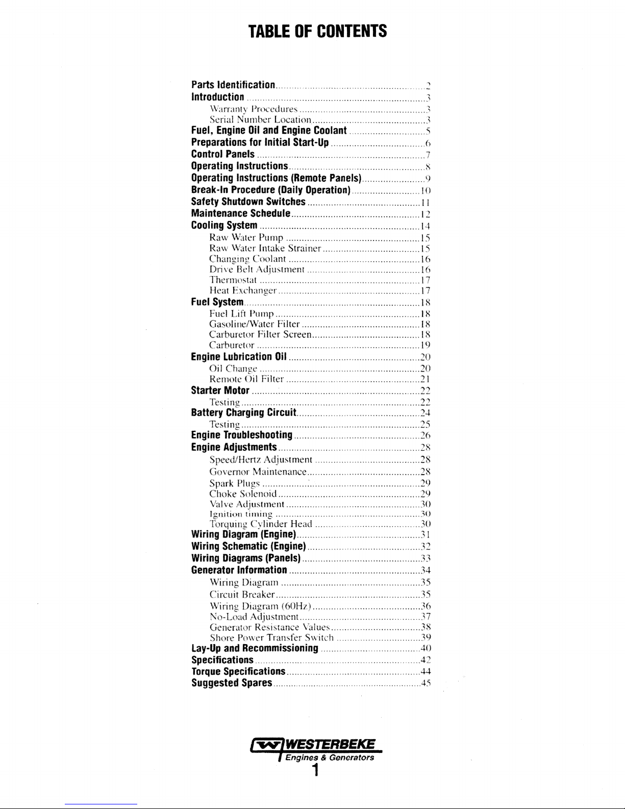
TABLE
Parts
Identification
Introduction
Warranly Procedures ............................................... .3
Serial Number Location ........................................... 3
Fuel,
Engine
Preparations
Control
Operating
Operating
Break-In
Safety
Maintenance
Cooling
Raw
Raw
Changing Coolant ..................................................
Drive
Thern1ostat
lleat Exchanger ......................................................
Fuel
Syslem
Fuel
Gasoline/Water Filter .............................................
Carburetor Filter Screen .........................................
Carburetor ..............................................................
Engine
Oil Change .............................................................
Remote Oil Filter ...................................................
Starter
Testing ....................................................................
Battery
Testing ....................................................................
Engine
Engine
Speed/Hertz Adjustment ........................................
Governor Maintenance ........................................... 28
Spark Plugs ................. : ..........................................
Choke Solenoid ......................................................
Valve
Ignition tirning .......................................................
Torquing Cylinder
Wiring
Wiring
Wiring
Generator
\Viring Diagram .....................................................
Circuit Breaker .......................................................
Wiring Diagram (60Hz) ......................................... 36
No-Load Adjustmem .............................................. 37
Generator Resistance Values .................................. 38
Shore Power Transfer Switch ................................ 39
Lay-Up
....................................................................
Oil
and
for
Initial
Panels
................................................................
Instructions
Instructions
Procedure
Shutdown
Schedule
System
.............................................................
Water
Pump ...................
Water
Intake Strainer .....................................
Belt
Adjustment ...........................................
............................................................. l 7
...................................................................
Lift
Pun1p
Lubrication
Motor
.......... ~ .....................................................
Charging
Troubleshooting
Adjustments
Adjustment ................................................... 30
Diagram
(Engine)
Schematic
Diagrams
Information
and
Recommissioning
OF
CONTENTS
........................................................
Engine
(Daily
SWitcbes
.......................................................
Oil
Circuit...
Coolant
Start-Up
....................................................
(Remote
Operation)
.............................
....................................
Paneis)
........................
..........................
...........................................
.................................................
.,
..............................
.................................................. 20
............................................
................................................
......................................................
Head
........................................
...............................................
(Engine)
(Panels)
...........................................
.............................................
..................................................
....................................
1 o
11
12
14
15
15
16
16
17
18
t8
18
18
19
20
21
22
22
24
25
26
28
28
29
29
30
30
31
32
33
34
35
35
..40
Specifications ............................................................... 42
Torque
Suggested
Specifications ...................................................
Spares
..........................................................
44
.45
2
3
5
6
7
8
9
Page 9

20AmpDC
Circuit Breaker
Lube Oil
Dipstick
PARTS
Fresh Water Coolant
Model Data Tag
FUI
IDENTIFICATION
Lube
OH
Fill
Exhaust Temperature Switch
Distributor
45° Exhaust Elbow
Oil Pressure
Switch
...
Heat Exchanger .
Control Panel
8A
&15AFUSES~
--~
/
Air
lntak~
DC Battery Ground
Connection
REAR
Starter with Solenoid
Flame Arrester
FRONT
AC
Connections---
Outlet
Gasdenser
Lube Oil Drain Hose
lwiWESTERBEKE
Engines & Generators
2
i--~-Water
Switch
Sea Water Pump
Zinc Anode
Temperature
Page 10
INTRODUCTION
This
WESTERBEKE
WESTERBEKE'S
technology.
and dependable perfonnance of our engines
Thank
In order
it
is
manual
manual carefully
throughout.
your nearest
· ·
This
provided
WESTERBEKE
equipment
for WESTERBEKE'
We
you
for
to
get
important that
is
designed
Should
WESTERBEKE
is
your
Operators
and
a Technical Manual
yourself,
WARRANTY
Your
WESTERBEKE
folder.
If
you
have
card registering
warranty registration
writing
with
model
and
number
commission
Generator
long
years
take
great
selecting WESTERBEKE.
the
full
use
you
operate
to
help
and
observe all.the safety precautions
your
Manual.
dealer.
If
contact your WESTERBEKE dealer
S Installation Manual.
is
a product of
of experience
pride
in
the superior durability
and
benefit from your
and
maintain it
you
do
this.
generator require servicing, contact
dealer for assistance.
A Parts Catalog
is
you
are
planning
PROCEDURES
Warranty
not
received a customer identification
your
warranty
form, , please contact the factory in
information, including
date
60
is
days
included
and
advanced
and
generators.
generator,
correctly.
Please read
is
also
available
from
to
install
in
a separate
after submitting the
the
unit's serial
this
your
this
This
WESTERBEKE
span
between printings of WESTERBEKE product
and
the
unavoidable existence of earlier WESTERBEKE
manuals.
WESTERBEKE
other
suppliers, must
sively
as
not
only
makes
representatives
be
consulted
product
software
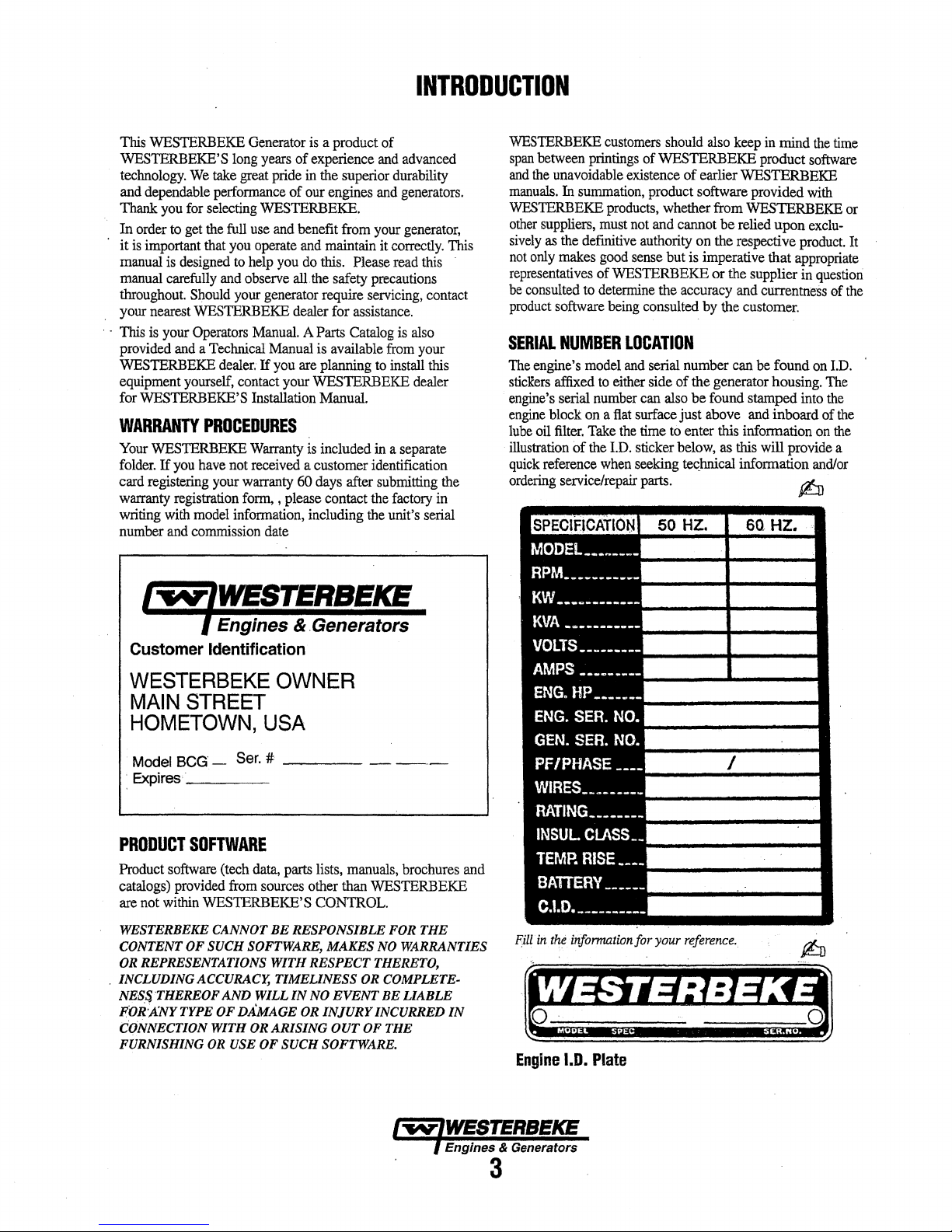
SERIAL
The
engine's
sticRers
affixed
engine's serial
engine
block
lube
oil
filter.
illustration
quick
reference
ordering
SPECIFICATION
MODEL
RPM __________
KW
___
customers
In
summation,
products, whether from WESTERBEKE or
the
definitive authority
good
ofWESTERBEKE or the supplier in
to
determine
being
NUMBER
model
to
either side of the generator housing.
number
on a flat
Take
of
the
I.D.
when
service/repair parts.
should
also
keep
product software provided
not
and cannot be relied upon
on
the respective
sense but is imperative that
the accuracy
consulted
and
by
the customer.
LOCATION
and
serial number can
can
also
be found stamped
surface just above and inboard of
the
time
to
enter this information
sticker
below,
as
this
seeking
te~hnical
50 HZ.
___
~----
_
G
_______
_
in
mind
appropriate
currentness of
be
found
will provide a
information
$:JJ
60,
HZ.
the
time
software
with
exclu-
product.
question
on
I.D.
The
into
the
the
on
the
and/or
It
the
Engines & .Generators
Customer
WESTERBEKE
MAIN
HOMETOWN,
Model BCG -
.
Expires·_----·
PRODUCT
Product software (tech
catalogs)
are
not
WESTERBEKE CANNOT
CONTENT OF SUCH SOFTWARE, MAKES NO WARRANTIES
OR REPRESENTATIONS
.
INCLUDING ACCURACY,
NESS THEREOF
POR'ANYTYPE OF DA0MAGE OR
CONNECTION WITH OR
FURNISHING
Identification
OWNER
STREET
USA
Ser.
#
----
SOFTWARE
data,
parts lists, manuals, brochures and
provided
within
from
sources other than WESTERBEKE
WESTERBEKE'S CONTROL.
BE
RESPONSIBLE FOR THE
WITH
TIMELINESS
AND
WILL
IN
ARISING
OR
USE OF SUCH SOFTWARE.
-
---
RESPECT THERETO,
OR COMPLETE-
NO
EVENT
INJURY
OUT OF THE
BE
LIABLE
INCURRED
IN
·
KVA
-~---------
VOLTS
AMPS
________
___
ENG.
HP----~-
ENG.
SER.
GEN.
SER.
PF/PHASE----
WIRES
________
RATING
INSUL
TEMP.
CLASS
RISE----
_______
BATIERY
C.1.D.
----------
Fill
in
the
informa.tionfor
Engine
l.D.
G
____
NO.
NO.
------
Plate
_
_
.•
_
_
your
I
reference.
Engines & Generators
3
Page 11

.
ORDERING
Whenever
generator
include a
needed
part
Also
will fit
specifications
NOTES,
As
this
maintenance
generator,,
CAUTIONS,
NOTE:
A
observed,
PARTS
replacement
and
engine
complete
(see
insist
upon
or
generic
as
CAUTIONS
manual
schedules,
critical
and
An
operating
CAUTION:
can
engine.
A
WARNING:
fa/lawed,
NOTE:
by
WESTERBEKE.
the
SPARES
Certain
WESTERBEKE
SUGGESTED
as
proper
way.
spares
on-board
NOTE:
manual).
the
about
can
A
carbon
engine
room.
AND
spares
fuel
WESTERBEKE
and
accessories
inventory
Also
available
These
drive
engine.
these
kits.
parts
are
needed,
model
and
serial
part
description
the
separately
WESTERBEKE
parts
are
frequently
original
equipment.
AND
takes
you
through
and
information
WARNINGS.
procedure
Procedures,
result
in
the
Ptocedures,
result
in
personal
monoxide
Affix
warning
this
decal
and
furnished
packaged
WARNINGS
the operating
troubleshooting of your
will
be
An explanation
essential
which
damage
which
injury
decal
in a visable
ACCESSORIES
will
be
needed
to
support and
generator or engine
SPARE
and oil
of
are
provide
Visit
our
PARTS).
filters
will
brochure
the
basic
can
provide
proper
Spare
Parts
service
website:
Often
be
difficult
you
to
assist
WESTERBEKE
Kits
spares
www.westerbeke.com
INTRODUCTION
always
provide
numbers.
part number for each
not
highlighted
to
if
not
or
If
has
when
even
with a suggested
(last
In
addition,
Parts
Catalog).
parts
because
made
to
the
same
procedures,
by
NOTES,
follows:
note.
strictly
destruction
not
prapedy
ar
lass
been
location
maintain
cruising
simple
to
you
page
needed
of
of
life.
provided
in
(see
items
obtain
along
in preparing
parts.
in
this
in
maintaining
to
the
your
your
such
learn
an
the
PROTECTING
Care
at
the
have
resulted
many
thousands
manufacturer
installed
operated
buyer/owner
NOTE:
Six
•
Proper
• An
efficient
anti-siphon
engine.
•
Changing
hours.
•
Proper
components
this
•
Use
•
Winterize
RECOMMISSIONING
UNDERSTANmNG
The
gasoline
ways
similar
are
vertical
overhead camshaft
a solid-state distributor
camshaft-driven.
lubrication
which
is
generator's
maintenance
The
most
proper ventilation, maintenance of the
system,
YOUR
factory
during
in a
WESTERBEKE
of hours of
cannot control
in
the
vessel
and
serviced in
operator.
important
engine
maintenance
manual.
clean,
steps
and
well-designed
break
to
the
engine
according
filtered
your
engine
THE
engine
driving
to
a gasoline
in-line,
system,
thermostatically
important
cooling
engine
that
system
and
which
The engine
and a fresh
requires
is
required of a
factors
INVESTMENT
assembly
generator
dependable
how
or
or
the
manner
the
field.
this
to
ensure
long
generator
prevent
oil
of
unleaded
according
exhaust
and
all
engine
to
the
section
fuel
installation.
water
oil
filters
maintenance
in
GASOLINE
an
AC
generator
automobile
the
engine's
is
chain-driven.
which
is
horizontally
incorporates a pressure
water-cooled
controlled.
the
same
gasoline
to
the
generator's
and
the
generator
and
thorough
capable
service.
where
the
in
which
is
up
to
generator
system
thaJ
from
entering
every
and
generator
schedule
to
the
JAY-UP
this
manual.
ENGINE
engine.
cylinder
head
The
mounted
engine
To a large
preventative
automobile
fuel
system,
back-end.
testing
However
generator
the
unit
the
life:
includes
the
I
00
operating
AND
is
in
many
The
cylinders
has
engine
type
block
degree,
longevity
ignition
of
the
is
is
an
in
an
utilizes
and
the
engine.
are
CARBON
WESTERBEKE recommends mounting a carbon
detector in
even
The presence
from
elbow/e:xhaust
If
carbon monoxide is present, ventilate the area
air
MONOXIDE
the
vessels living quarters. Carbon monoxide,
in
small amounts,
of
carbon monoxide indicates
the engine or generator or
hose.
and
correct
the
DETECTOR
is
problem immediately!
deadly.
from
the
an
exhaust
exhaust
monoxide
with
.
leak
clean
Engines & Generators
4
Page 12
FUEL,
ENGINE
OIL
AND
ENGINE
COOLANT
GASOLINE
·A
CAUTION:
higher.
Etbana/
BefSDll°'e
a~/e;far.·use.!R·tbesemo*/s
warranty.
Gaisoline With an
highar
than
108/e
and
mllY
Care
Of
The
Use
only
clean properly filtered
components
particles
these
and
keep
unsatisfactory by careless handling or improper
facilities.
engine's daily use is clean
advisable:
Purchase
Install
metal
and
the
in
which might
finely
finished
it
clean.
To
a well-known
and
regularly service a
bowl
type
engine.
Ilse
unleaded
gasa/lne'must
·wif~
hillher.1111rce11tages
89
Octaae
not
exceed
of·Ethaaol
and
ETHANOL
lE10) is
void
Fuel
the
unit's
The best
assure that the
filter/water separator between the
content
nOt
warr~nty.
·
•llowed'
. :
Supply
fuel!
The
fuel
system are very critical; dirt
pass
through the filter
parts.
It is important to buy clean
fuel
can be rendered
fuel
going into the tank
and
pure, the following practice
brand
of
fuel.
good,
Coast Guard
gasal/ae
E10
caa
cl~~
can
(100/o).
are,
not
void
the
of
damage
storage
for
approved
fuel
or
some
fuel,
your
tank
.
,
is
ENGINE
WESTERBEKE
and
chemicals
The
run at proper temperatures
the engine to the coolant
cooling
quality
Additives
balanced,
The distilled water
being polired into the cooling circuit.
NOTE:
antifre~
A
engine
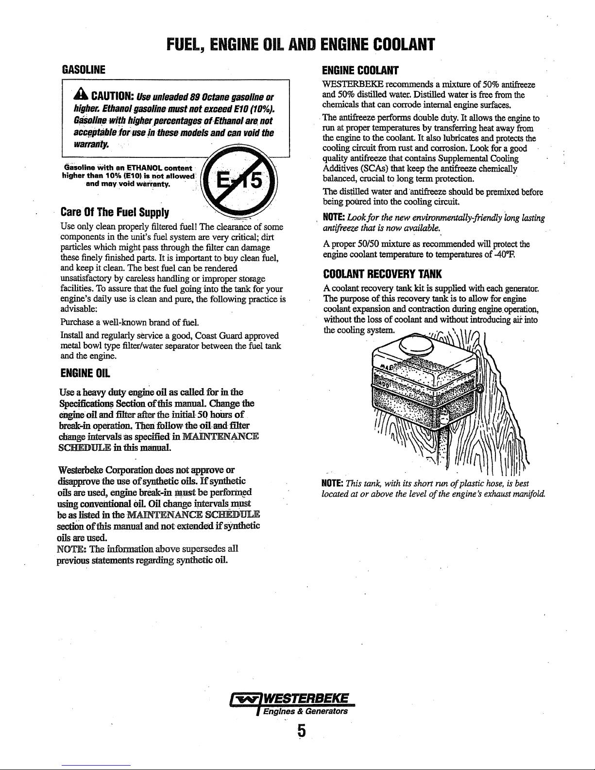
COOLANT
A coolant recovery tank kit is supplied
The
coolant
without the loss of coolant
the
COOLANT
recommends a mixture of
50%
distilled
antifreeze performs double
circuit from rust and
antifreeze that contains
crucial to long term
Look for
proper
SO/SO
coolant
pmpose of this recovery tank
expansion
cooling
water.
Distilled
that can corrode internal engine
by
It
(SCAs)
that
that keep
and
·antifreeze should
tlie
new
environmentally-friendly
is
now
available.
mixture
temperature
RECOVERY
system.
as
and
contraction
recommended
TANK
and
water
du~.
transferring
also
lubricates
corrosion.
Supplemental
the
antifreeze
protection.
to
tempCratures
is
to
during
without
\
50%
antifreeze
is
free
from
surfaces.
It
allows
the
heat
away
and
protects
Look
for
Cooling
chemically
be
premixed
will
protect
of
-40°R
with
each
allow
for
engine.operation,
introducing
\{i
the
engine
from
the
a
good
before
'wng
lasting
the
generator.
engine
aii:
into
to
ENGINE
Use
Specifi~
eilgine:
break-in
change intervals
SCHEDULE in this
Wesrerbeke
disapprove
oils
using
be as
sectiOD.
oils
NOTE: The infor,mation above supersedes all
previous
OIL
a
heavy
duty
enghie
oil as called fbr
Section oftbis manual.
oil
and
filter after the initial
opetatian.
Corporation does
the use
are
used, engine break-in
conventional
listed
in
of
this
are
used.
statements regarding synthetic
TJ:ten
follow the
ti
specified in MAINTENANCE
manual.
of
synthetic oils.
oil.
Oil
change
the
MAINTENANCE SCHEDULE
manuai
and
not-extended
SQ
-0ilan.d
not
approve or
If
~ust
be
iJ:ltervals_
in
the
Change
hoUrs
filter
synthetic
pertbr:in~
must
if
sYnthetic
oil.
of
the
NOTE:
Thi.s
located at or
tank,
with its short
above
the
level
of
run
the
of
plastic
engine's
hose,
exhaust
is
best
manifold.
Page 13
PREPARATIONS
COOLANT·
FILL
FOR
INITIAL
START·UP
OIL
DIPSTICK
4-MAX.FULL
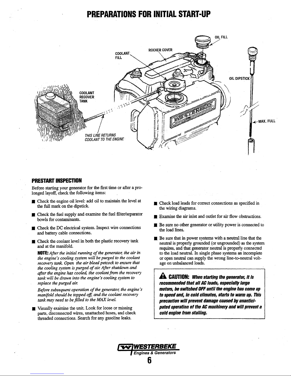
PRESTARTINSPECTION
Bef91'e
starting
layoff,
longed
• Check
the
full
a Check
bowls
a Check
and
battery
a Check
and at
NOTE:
the
engine's
rec<JVery
the
cooling
after
tank
replace
Before
manifold
tank
•
Visually
parts,
threaded
your
check
the
engine
mark
on
the
fuel
supply
for
contaminants.
the
DC
electrical system.
cable
the
coolant
the
manifold.
After
the
cooling
tank.
Open
system
the
engine
will
be
drawn
the
purged
subsequent
should
may
need to
exainine
disconnected
connections.
generator for the
the following
oil
level:
add
the dipstick.
and
examine
connections.
level
in both
initial
running
system
will
the
air bleed
is purged
has
cooled,
into
air.
operation
be topped
be
filled
the
wires, unattached
<Jf
the
the
engine's
of
off,
to
the
unit.
Look
Search for
first
items:
Qil
to
maintain
the
Inspect
the
plastic
of
tlJ.e
generator,
bepurged
petcock
air.
After
coolant
cooling
the
generator,
and
the
MAX
for
loose
any
time
or after a pro-
fuel
filter/separ:ator
wire
recovery
to
to
shutdi:Jwn
from
system
coolant
leveL
or
missing
hoses,
and
gasoline
the
level
connections
tank
the
air
in
the
coolant
ensure
that
and
the
rec<JVery
to
the
engine's
recovery
check
leaks.
at
a
.Che(:kl()ad
the
Wiring
•
Examine
• Be
sore
the
load
a
Be
sure
neutral
isproperly.grounded,.(or.ungrolJJlded)
requires,
to
the
load
or
open
~ge
onunbalanced
A
CAUTION:
teOO/llllltllltltld
·motors,
'"
speff/
precaution
patsd
operation
cold
qine
leads
for
correct
diagrams.
the
air
inlet
~d
no
other generator or
lines. ·
that
in power
and.
that
generat()r
neutral.
neutral
can
In
supply
loads.
If/lien
tbatall M
be
swltdled
anti,
will
tram
In
cold
prtJvent
al the
stalling.
tiff
<;onnections
outlet for air
utility
systems
single
with
neutl'at
phase
the
V'lrong
start!PI!
loar$,_
until•
t:lialates,
damage
AC
machinery
.as
specified
flow
obstructions.
power
is
connected
a neutral line
is
properly
systems
line-to-neutral volt-
ti!•
fP11Jllflllor,
that
as
the
connected
.~
incomplete
n
Is
11$/lf1Dlallylarg11
1111!Ji.n11
b.f!s
t:Oflle
·starts
to
watm
up.
callSfld
by
and
unantlBJ.
will
prevent
in
to
the
system
up
This
a
Engines & Generators
6
Page 14

CONTROL
PANELS
DESCRIPTION
The generator mounted control
ON
switch (black), a START switch(white) and a
switch (red).
The
ON
switch provides power
switch by-passes the protective oil pressure shutdown switch
until the oil pressure reaches 5 -
The
START switch energizes the start solenoid/starter which
cranks the engine. This switch will
switch is depressed and held at the same time.
The
STOP switch will twn
switch must
The
panel also has two fuses to protect the
•·A
Stow-blo
•An 8 Amp
any
REMOTE
An
optional remote start/stop panel is available for
controlling the generator from a remote location.
This panel has the same ON, START, and STOP functions
previously described. Also included is a green LED light
which glows once the engine/generator has reached
rpm's. The purpose
release the
engine/generator
be
depressed until the stop sequence
15Amp
Fuse
Fuse
to
protect
optional
remote.
~a'!_efs.
START/STOP
of
the LED is to alert the operator to
START switch. It is also an .'ndication that the
is
running.
panelis
to
the start circuit.
10
psi.
not
off
the engine/generator.
to
protect
the
start
the
engine
operating
PANEL
(OPTIONAL)
equipped with
operate unless the
DC
circuit:
circuit.
circuff
15
RECORDING
FOR
8
an
STOP
nus
nus
is
complete.
ancf
AMP
FUSE
HOURMETER
MAINTENANCE
AMP
FUSE
600
on
HOURS
REMOTE
An optional remote instrument panel is available which
includes a water temperature gauge, oil pressure gauge,
DC charging voltmeter, operating hourmeter
switches.
REMOTE
The remote instrument panel has two sending
installed on the engine block, a water temperature sender and
an
oil pressure gauge sender. Plugged ports for each are
located on the engine.
installed in the thennostat housing and the oil pressure sender
is adjacent to the oil pressure switch.
on the threads
each sender are tied
wiring harness).
The blue wire is for the oil pressure sender and the
is for the water temperature sender.
between terminal board connections
removed. Refer to the REMOTE INSTRUMENT WIRING
DIAGRAM
NOTE:
installers responsibility to comply with the
standards
INSTRUMENT
INSTRUMENT
of
both senders. Electrical connections for
in this manual.
When
installing the optional remote panels, it is
33
CFR
part 183.
PANEL
PANEL
The
water temperature sender is
off
next to the senders location ( in
(OPTIONAL}
INSTALLATION
Use sealing compound
If
there is a jumper
T-1
•.
·
and
U.S.
aQd
start/stop
units
to
tan wire
T-2,
it should
Coast Guard
be
the
be
the
Engines & Generators
7
Page 15

OPERATING
INSTRUCTIONS
STARTING
A
for a minimum
WJntilatlng
fumes
1.
Depress
this
2.
Depress
· starts,
the
NOTE:
the
oil
pressure
maintain
3.
Release
·A
when
caused
and
Once
ator
and
ature
lf
an
gauges
NOTE:
This
and
when
111EGENERATOR
WARNING:
from
primes
release
ON
switch a
Keeping
pressure
to
the
CAUTION:
starting.
by
will
prevent a cold
The
engine
allow
(130°-150°
optional
for
nonnal readings. · · · ·
Soin~·unstable
condition
the
..
Ventilate
of
five
blowers
the
generator
the
ON
switch
carburetor.
the
START (white),
the START switch. Continue
few
the
ON
shutdown circuit allowing the oil
rise
enough
ignition circuit
the
ON
switch.
AllAC
This
precaution
unanticipated
is
running
the engine
Fl
55°-56°C)
instrument panel
should smooth our
generator
the
generator
mlnut•
remove
seconds
switch depressed by-passes
to
loads
running
prior
any
explosive
comjlarlment
and
hold
Continu.e
when
longer.
close
the
mast
will
operation
engine
ttom.sttllllag.
apply
to
wartn
before applying
is
installed, tnonitorthe.·
may
(l$,th.e
loads
a~
appJit4
A
compatfment
to
starting.
gasoline
and
it
down
(5-15
to
depress
the
geneyator
. ·
switch
an.ti
be
swllched
pre"6nt
of
AC
machinery
-"-
a ligbtJoad
up
ti:>
qperating temper-
the
The
bilges~
•.
sec~nds),
ON.
to
.engage
exhaust
pump
c11olin!J
entettll.e
manifold
frorll
throug/Fhull
cogecting
Engine
warrantable
in
mind.
STOPPING
1.
Remove
generatorto
its
off
damage
.·1
operating temperature).
.
2.
Depress
~.
When
NOTE:
the stop
to
the gener-
heavy
·.
loads.
panel.
CAUTION:
engine
with,
is
pumping
system
happening
damagetesultlngfrom
the
In
an
switch,
Prolonged
starting
raw
water.
raw
during
engine's
once
the
the
emergency,
cylinders
the
exhaust
byt:Joslng
Shutoff,
the
cause
issue:
the
THE
GENERATOR
AC
loads
run
for
an
STOP (red)
generator stops, release the STOP
remove
t;ra11klng
can
result
In
fllllngthe
This
may
water
through
cranking.
draining
of
the
This
by
way
system
the
raw
the
excessive
raw
(Jwner/operator
·
from
the
added 3
the 8
to
S minutes
switch.
if
the
generator will not stop
amp
ju.se
Intervals
happen
tile
miff
of
the
fills.
Prevent
water
exhaust
engine
water
should
generator
in
engine
because
raw
water.
waler
exhaust
supply
muffler,
entry
and
(this
the
control
occ1'tNiJacd!(:l,~ng:i11.e.
e~gtne
'warms'
up
without
the
can
this
and
cranking.
is
not
a
keep
this
allow
the
stabilizes
switch.
using
·
.·Engines
& Generators
8
Page 16

OPERATING
ABNORMAL
An
abnormal stop
and
comes to a stop
may
cause damage
unsafe operating condition. The fault stop conditions
1.
Overspeed condition!.
2.
High
3. Low oil pressure.
4. High exhaust temperature.
Should a fault condition occur, the engine will shut
and
the green LED light
indicating that a fault
should
OVERSPEED
In the case of
must be reset before re-starting
the
Stop switch mtarily
sequence.
If
the overspeed switch itself
depressing
T-1
coil connection
end of
only
as a test.
successful, replace
Do
not
switch.
STOP
is
one
in
which
the
generator
as
a result of
to
the
engine temperature.
on
has
be
located (see ENGINE TROUBLESHOOTING).
an
operating fault which
engine, the generator, or create
the remote panel will
occurred. Once detected,
ceases
SHUTDOWN
an
overspeed shutdown, the overspeed circuit
the
generator. Simply
then
the
the
T-1
run
the generator
STOP
from
wire
with
Re-start
the
proceed with
is
switch
will
the
overspeed switch
electrical
the
generator,
faulty
overspeed switch.
with
faulty
not reset
tape.
out replacing
the
and
re-setting it
the
By-pass
if
this by-pass
the
normal
circuit,
and
this
overspeed
go
tape
is
to
are:
down,
off
the
fault
depress
start
by
lift
the
circuit
INSTRUCTIONS
NOTE:
Overspeed switches draw a small amount
run
an
the
amperage (25 milliamps) at all times once the generator
connected to its starting battery. This amounts
mately 18 amp-hours
concerned with this slight amperage draw during normal
. seasonal operation.
unused for many months, it
amp ignition fuse from
tum
off
the
generator's starting battery
A
CAUTION:
shutdown
tampering
would
injury
and
REMOTE
The remote startpanel
operate the same
except that they have
remote location (where
be
audible). The green
generator is running
switch should be released. For the remote start/stop sequence
refer to
always
with
cause
should
cause
the
PANELS
STARTING
in
a month. It is not necessary
However,
It
is
be
installed
the
overspeed
it
to
malfunction,
the
generator's
generator
as
the generator mounted control panel
green
LED
at
about
THE
if the generator set
is
best to either
the
controlpanel
very
important
and
functioning.
shutdown
could
belt-driven
to
run
away.
and
the remote instrumentpanel
LED lights for starting
the
sound
of
the
lights indicate
600
rpms.
GENERATOR
remove
on
the
switch..
that
the
module,
be a cause
governor
generator.may not
when
That is
on
the
of
to
approxi-
to
be
is
to
be
the
8
generator or
overspeed
Any
which
of
fail
at
a
the
when
the
start
previous page.
is
A
the
Refer
manual.
to
WARNING:
overspeed
the CONTROL
switch
Do
not
operate
by-passed.
PANEL
the
generator
WIRING DIAGRAM
with
in
this
Engines & Generators
g
Page 17

BREAK•IN
BREAK·INPROCEDURE
After
the.generator
and
then
encourage a fast
20%
to
60%
A
CAUTION:
tor
by
running
After
the
first
can
be
increased
vary
the
foad.
Avoid
.
<lverlo~d
smoky
eXhaust
Monitor
it
at
hertz,
by
To
the
breaker
NOTE:
current drawn
amperage drawn
age. See
the
within
the
1800
rpm
control
the
current
protect
against
generator;s
that
Be aware
GENERATOR
has
been
started,
warm-up.
of
full
load
for
the
first
·Do
not
attempt
without
10
~all
with
currentbeing:d.rawn
genei;a.tors~
to
produce
of
drawn
output
is·
rated·
required
a
/aad~
hours
of
the
generators'
to
the
full-:load
time:;.
¥
l'edoCed:
the
generator's engine
from
unintentional
at·
of
motor starting
can
be 3
output
tating.
60
hertz;
the
leads
should
the
rated output
for
starting
to
5 timesnormalrunning
INFORMATION
rated
··
9yertoa.d
Since
generator.
overloading
check
Run
the
10
hours.
to
break-in
operation,
output;
i~
voltage.
from
i:he
generator
the
generator
or
at
1500
break~in
be
routed
of
the
toads
anti
motors.
in.thisfrtanua.L
PROCEDURE/DAILY
NOTE:
This
for
proper
generator
operation
between
is
reached
condition
A
your
genera-
periods
OPERATION
Some
unstable
should abate
and
loads
CAUTION:
of
time
Do
not
without a load
generator.
the
load
then
periodically
·
.signa}~
and
by
a
frequency~
and
keep
operates
to.produce
cjfi:he
through a circuit
generator.
th~
This starting
is
governed
generator,
high
r:zmper-
50
·
STOPPING
Remove
Allow
the
operating
CONTROL
NOTE:
After
.
the
nuzintelltlnce
.
GENERAToR
Once
be
governor
during
this
period
under
ment
speed
the
the
ENGINE
may
adjustment
.
tHE
GENERATOR
the
major
AC
generator
temperature
PANELS).
the
first
schedule for
ADJUSTMENTS
generator
engine's
(see ENGINE SPEED (HERTZ) ADJUSTMENT
also
has
adjustments
break-in period (first 50
ADJUSTMENTS. A
be
required
(see
running may occur
as
normal operating
are
applied.
operate
the
being
loads
fu:im
the
tb.run
for a
few
and press
SO
hours
beeh
GENERATIOR
of
the
placed
required
in
conjunction
the
STOP
generator operation
50 hour service
in
for
no-load
~n
a cold
temperature
generator
placed
generator
minutes
operation,
engine
INFORMATION).
to
switch
speed
hours)
voltage
with
for
long
on
the
one
stabilize
down,
check.
there
(hertz)
or
the
engine's
engine.
at a time.
the
(see
check
may
after
adjust-
CHECKLIST
Follow
this
checklist
•
R.ecord
the
hounneter reading
relate
to
the
maintenance
•
Visually
II
Check
•
Check
•
Check
•
Check
a
Check
•
Check
blow-by
•
Confirm
When
When
When
inspect
the
the
your
the
the
for
abnormal
sounds.
exhaust
the
engine
the
engine
the
engine
oil
level
coolant
fuel
starting
drive
each
day
before starting
in
schedule).•
the
engine for
(dipstick).
levelin the coolant
supply.
batteries
belts
for
.noise
smoke:
is
cold
is
wann - almost
is
overloaded -
fuel,
(weekly).
wear
and
such
-White
your
oil,
proper
as
knocking,
Smoke.
Smokeless.
some
your
log
(engine
or
water
recovery
tension
vibration
Black
Smoke.
generator.
hotirs
leaks:
tank.
(weekly).
and
Engines & Generators
10
Page 18

SAFETY
SHUTDOWN
SWITCHES
. SAFm
The engine
Should a shutdown
finding
Engine
TROUBLESHOOTING
The following is a
switches:
SHUroOWN
is
protected
occur,
and
correcting
starts,
runs
and
desCription
SWITCHES
by
a variety
do not attempt
the
cause. Refer
then
section
of
shuts dbwn in the
of
this manual. .
of
these automatic shutdown
shutdown switches.
to
restart without
to
the heading
ENGINE
EXHAUST
TEMPERATURE
SWITCH
Exhaust
An
elbow. This switch will open and interrupt the DC voltage tn
the ignition coil (which turns
switch's sensor indicate an excessive exhaust temperature
inadequate supply.of raw water coolant causes high exhaust
temperatures).
(
127° -132"
Temperature
exhaust temperature switch
This switch opens at 260" - 270° F
C)
and resets
Switch
at
approximately
is
located
OFF
on
the
the engine), should the
22."i'F
exh;~ust
(107'' C)
(an
low
Oil
Pressure
A low oil pressure
engine's oil gallery. The switch
pressure. Should the
t11e
switch
will open interrupting the DC voltage
ignition
coil (which turns
Oil
FILTER.
Switch
shutdown
engine's
1.·~¥.-V~
~Ji
switch
oil pressure
OFF
the engine).
LOW
is
located off the
is
kept closed
OIL
PRESSURE
fall
by
engine oil
to
10 -.15
to
the
SWITCH
psi,
r.;:;;
High
RPM
Shutdown
An overspeed shutdown switch shuts
by
grounding out the ignition system should the engine's
speed reach approximately
momentarily depressing the
cause
of
the engine
Engine
Circuit
Breaker
The.
generator's engine is protected
manual reset circuit breaker (20 amps DC). Excessive current
draw
or electrical overload anywhere
wiring or engine wiring will cause
the generator will shut down because
event
breaker interrupts the DC circuit
should occur, check and repair the source of the problem.
After repairing the fault, reset the breaker and restart
generator.
Switch
2175
STOP
overspeed
OFF
the generator set
rpm. Reset the switch b)
switch. (Make sure the
shutdown
to
is
cnrre.cted).
by
an
engine mounted
in
the instrument panel
the breaker
the K2-run
the
to
opened
relay.
trip.
If
the
In
this
this
High
Water
A
high
housing. This switch
to
the
ignition coil (which turns
fresh water coolant's operating temperature reach
approximately 205" F (96" C). ·
This switch resets at 195" F
Temperature
water temperature switch
will
Switch
open and
(!OTC).
is
located on the
inte1rupt
OFF
thcm10st.at
the
DC
voltage
the engine). should
l"flV'iWESTERBEKE
~
the
Engines'&' Generators
11
Page 19
A
WAllNING:
running.
11$8
the
curreot
serrlcin9
NOTE:
Many
more
difficult
MAINTENANCE
Nsver
attetnpt
Wear
tbeprap11raletyeq'1i/1"1ent
t~ols
,,,,
any
of
the
e11gi11e'I
of
the
following
and
may
require
to
perfQrm
,.ch/o/l.111$coanect
DC
BlilctriQal
mamtenance
the
expert
SCHEDULE
any
service
such
the
equipment.
procedures
knowledge
while
as
g11119/e$
battery
are
$imp
of
a
service
terminals
the
engine
and
gloves,
le
but
others
mechanic.
Is
and
when
are
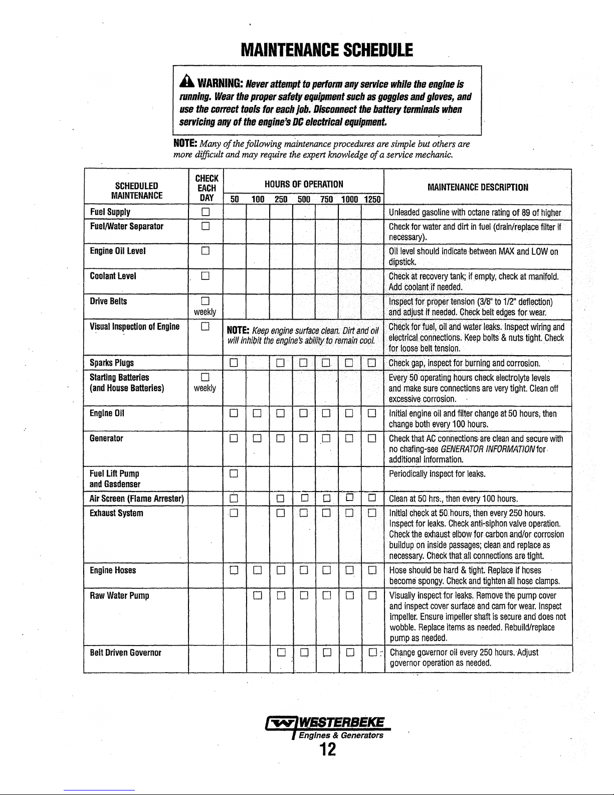
SCHEDULED
MAINTENANCE
Fuel
Supply
Fuel/Water
Engine
Coolant
Drive
V!sual
Sparks
Starting
(and
Engine
Generator
Fuel
and
Air
Exhaust
Engine
Raw
Belt
Separator
Oil
Level
Level
Belts
Inspection
Plugs
Batteries
House
Batteries)
Oil
Lift
Pump
G11sdenser
Screen
(Flame
System
Hoses
Water
Pump
Driven
Governor
of
engine
Arrester)
CHECK
EACH
DAY
0
0
0
0
D
·weekly
0
0
weekly
HOURS
OF
OPERATION
5Q
100
25.0
500
NOTE;.
Keep.
engine
surtace.cle~n·Dirta~r:frJif
wlll
lnhi/Jit
too
engifie'S
ab.lffJYt~iem~in.cgpl.
[j
0
0
0
0 D
·
..
··D··.•
0
. •
I
0
c-
0
D
D
D
0
0
0
D
0 D
D
D
O D 0 0 D 0
D 0 D D
.750
·cc-
.
0 D
·o~
D D
..
0
..
D.
0
1000
D
0
D
0
.·
. i
••
MAINTENANCE
1250
Unleacled
Check
·
necessary).
Oil
clipstick
.
1
crieC:k~recovery
.:Acid#P91ilJJt:if·n.eeded.
· · ·
••·
• ·
··
1
"lli$g~oftorpr~perterlston
. . I
a,ng
•tjbep~:tor
' ·
.•
eleetncat
tor19~sebe~tt!nsiqn.
c'
Eve~
and
ei.<c.essive.
0
Initial
change
D
Check
no
addition~l
Periodically
0
·Clean.
>o
Initial
lnspept
Check
buildup
necessary~
D
Hose
oecome
Visually
and.
impeller.
wobble.
pump
0
~
Change
governor·
gasoline
for
water
and
level
should
indicate
•.
tan~j.jf
~cllll~lifntieded•
fuer;
oil
aild
cortnectio~s.
50
ope~ting
make
sure
~nnections
porrosion.
engine
oil
and
both
every
that
AC·
connections·
chafing-see
at
check
should
inspect
GENERATOR
lnformation.
Inspect
50hrs~;
then
at
50J1ours;
for
leaks.
Ch.eek
the
e,xtiaust
on
inside
passages;
Clleck
that:all
be.
hard
spongy.
Check
inspect
tor
cover
Ensure
impeller
Replace
items
as
needed.
gooernor
oil
operation
DESCRIPTION
with
octane
rating
of89
of
higher
dirt
In
fuel
(drain/repl~e
between
MAX
empfy,
check
(3/8''.
fo
1/2·
9~1ick
belt
edges
v\iaterleaks;•
Keep
·.
h~!Jrs
filter
100
hours.
tor
leaks.
every
then
anti-siphon.
elbow
for
c~n.oections
& tight
~nd
leaks.
surface
shaft
as
every
as
needed.
Inspect
bolts & nutS
·
check
electrolyte
are
very
change
at
50
are
clean
INFORMATION
100
hours.
every
250
valve
carbon
and/or
clean
and
Replace ~ hoses
tighten
all
Remove
the
and
cam
1or
is
secure
needed.·Rebuild/replace
250
!lours.
filter
and
LOWon
at
manifold.
defle~on)
ror
wear.
wiring.
tight.
levels
tight
Glean
hours,
and
secure
for.
hours.
operation.
corrosion
replace
are
tight
hose
clamps.
pump
cover
wear,
Inspect
and
does
Adjust
if
·
and
Check·
·.
-"-
off
then
with
as
not
.:
·
lw;UfSSTElllJI!~
I
Engine/$
& Generators
12
Page 20

MAINTENANCE
NOTE:
l
:H
t''ngtne
e11gi11e
huun
,-i
-----,,--·---~-~·-~--~-'
I
I
SCHEDULED
~~~~TEN~N._ff_
I
Heat
Exchanger
CHECK
EACH
-~y
r1111nmg
1 -
j
--
-~0_
1·
0 O O ! O 1 O O ' 0
hourtli1/'!er
ti11n'.
HOURS
- · --
110~
);;UUtte Jo
Of
--
OPERATION
- -
250
_
50~750
! , I
L : \
I
Coolant
System
I j
I I I
l
Start~-r_M_o_t_o;------·---<c----+----+---f
l
I I l · I
r
Distributor
----+--0--<>---+i
' O
'
---+-1
-0--+1--j,___..__O_--+---C--hr-:c_.k_s_o_le-110_1_d_a_n1-.-m-{-1to_r_fo_r_c--o-n--o-si-on-_-R_e_m_o_vc-n--<
'
1
1
--1-·
0
SCHEDULE
/p'.!,_
r1>ur
r·n,~ine
i!uuts·
---r-
· -
-
__
11_!)0
_j
~
l
50
___
c:.:an
;,,,p
for
and
pnnon
Ci1(;Ck
and
---r1_000
--
tir
H'\:01'1
EXPLANATION
~-
or
replace
clean
out
f!usl-:.
and
;mtltreeze
luonc:ite
Clean
dnve.
1go1t1on
------"-----
Of
SCHEDULED
MAINTE~~~f~
anofle
Open
c!ebns
Remove
and
refill
cooling
rn:x
and
!utJricate
heat
pressure
system
every
________
exchanger
ever;
1000
testing
wittl
500
holirS
!lie
start
_
end
hours
ot
motor
;----------·-----
·Engine
I
l
I
t···---·----,..-~~-------<~---·--------+----+---
1
I
!---------·-----+----+-----+-·
I
Cylinder
Compression
Valv__e_~t:aran~:
·Engine
·Exhaust
Carburetor
Timing
Elbow
Filter
and
____
Belt
~
Screen
__
_,_
_
_,_
__
·-rr
Ii
0 0
O O
111
1
0
0
d1S!!1'.lu!Qr
lncorrec1
Inspect
Test
exhaust
castmg
WARNING:
carbor
Clean
cap
valve
every
elbow
is
corroded
A
detective
rnonoxide
after
50
every
and
rotor.
clearance
500
hours.
for
or
t;ours
of
250
operating
will
result
Replace
casting
deteriorated
extiaust
elbow
operation.
hours.
in
a!
3000
can
Clean
hours
Replace
cause
and
1!
13
Page 21

COOLING
SYSTEM
DESCRIPTION
Westerbeke marine engines are designed
fresh water cooling. Heat produced in the engine
tion
and
friction
is
transferred
to
fresh water coolant
circulates throughout the engine. This circulating fresh water
coolant cools the engine block,
the engine oil. The heat
fresh water coolant
exchanger, similar
water
flows
fresh water coolant
ferred
to
the fresh water coolant
tube walls to the raw water which is then pumped
through
to
raw water
in
function
the
flows
its internal moving
is
transferred externally
by
to
an
tubes
of
the heat exchanger
around
the,
is
exhaust system where finally it is discharged overboard.
In
other words,
this coolant
the
engine is cooled by fresh water coolant,
is
cooled
by
raw
water, and the raw water carries
the transferred heat overboard through the exhaust
the
fresh water coolant
dent of each
other.
and
raw water circuits are
Using only fresh water coolant within the
engine allows the cooling water passages to stay clean
free
from
harmful
deposits.
-
and
equipped
by
parts,
from
means
of
a heat
automotive radiator.
tubes; engine heat
conducted through
into
system.
indepen-
r---.....,
WATER
INJECTED ELBOW
ENGINE
............
-----
for
combus-
which
and
the
Raw
while
trans-
the
the
and
------
Coolant
A coolant recovery
and
contraction
cant
loss
ing
system.
engine manifold level
COOLANT
COOLING
PRESSURE CAP
Recovery
tank
during
of coolant
This
and
tank should
EXPANSION
KEEP
THESE
A'FULL
THE
COOLANT
CLEANER
DIAGRAM
Tank
allows
for
engine
engine operation,
without
and
FLOW
WORKS
introducing
be
located at
should be easily
!TO
TANK
PASSAGES
OF
COOLANT
RECOVERY
WELL)
(TYPICAL)
.
without
COOLANT
CLEAR
TO
TO
AND
TANK
(A
coolant
expansion
any signifi-
air
into the
or
above
accessible.
RECOVERY
ENSURE
FROM
PIPE
cool~
the
·
·FRESH
WATER¢
··
RAWWATER
NOTE:
Periodically
sure
cap.
good
condition
closes
tightly.
.....
Ensure
that
and
Carry a spare
check
the
check
·MANIFOLD
•PRESSURE
CAP
the
condition
upper
and
that
the
vacuum
cap.
of
lower
INCOMING
RAW WATER
the
manifold
rubber
seals
V{llve
.operis
pres-
are
and
in
RAW WATER DRAIN
14
Page 22

RAW
WATER
NOTE:
Always
the strainer will
A
clean
raw
water
engine's
strainer
in the glass
Perfonn
operation:
1.
2:
3. ·
4.
5.
6.
7.
NOTE:
aground.
If
normal
may
raw
cooling
when
the
Close
the
Remove
Clean
the
Replace
Reassemble
Open
the
Run
the
Also follow
the
engine
reading, the
have been
water
through
should
following
raw
and
the
seacock.
engine
temperature
INTAKE
install
the
always
int.alee
system.
making
glass.
your
be
clear.
maintenance after
water
clean
the
washer
and
install
and
the
above
cause
caught
up
tQ.e
cooling
~
STRAINER
strainer at or below
be
self-priming.
strainer is a
Include a
periodic engine
seacock.
strainer
if
necessary.
the
check
procedure after
gauge ever
may
in the
vital
visual
filter.
strainer.
for
leaks.
shows
be that silt, leaves
strainer,
system
COOLING
the
waterUne
component
inspection
check.
every
a higher
slowing
100
·
having
or
the
of
The
hours
run
than
grass
flow
of
the
this
water
hard
SYSTEM
RAW
so
of
of
The
non-ferrous,housjng
has
wiililii
On
always
(an
when
operation.
are
up.
broken
SCHEDULE.
NOTE:
(seals
chase
Changing
Close
and,
impeller
Move
push
bling,
gasket.
WATER
raw
flexible
ihe
no account should this
be
impeller kit}.
lubricant
cautioned
The
or
Should a failure occur with
and
a
the
with
the
the impeller into
apply
Open
PUMP
water
pump
pladeS
which
@peller
a spare impeller
Such
mw
tom
bearings),
new
raw
the
out of the
blades
housing,
Raw
(mw
failures
to
make
water pump
impeller
pump
and
the
Raw
water
aid
oftwo·small
pump.
to confonn
a thin
coating
the
~w
is a self-priming,
and a Neoprene
wipe
water
water)
are
sure
should
blades.
it
may
ntbuild the
Water
int.alee
the
water
against a curved
producing
pump
fJ'e
and
impeµer
pump
impeller
is not present
not
warrantable,
raw
water
be
inspected
See
MAINI'ENANCE
the
be
more
original
Pump
valve.
Remove
screwdrivers,
Install
the
to
the
c:urved
pump's
of
lubricant
int.alee
housing.
valve.
rotary
pump
impeller.
The
cam
the
pumping
run
dry.
There
cover
gasket
failures
during
engine
and operators
flow
is
present
periodically
pump~
cost efficient to
internal
pump
as a
1...,eller
the
pump
carefully
new
impeller
cam
plate
When
assem-
to
the impeller
with a
impeller
plate
action.
should
aboard
occur
at
start-
parts
pur-
spare.
cover
pry
and
gasket.
and
and
for
the
SEAUllG
WASH~
RAW
The
raw
impeller
water
water
through
the
heat
ing
fresh
into
the
ing the exhaust
water
discharge
WATER
source
strainer.
is
COOLING
water
fiow
pump.
This
(ocean,
The
the
raw
water
exchanger
water
coolant.
water-injected
gasses.
discharged
pressure.
RAW
WATER
OWNER
INSTALLED
CIRCUIT
is
created
pump
draws
lake,
or
raw
water
pump
tubes)
where it
~.raw
eifiaust
This
overboard
INTAKE
STRAINER
(TYPICAL)
by a positive
water
river}
through a hose
passes from
to
the
heat
cools
water is
elbow,
mixture of exhaust gas
by
the engine's exhaust
displacement
directly
the
exchanger
the
engine
then
mixing
from
strainer
discharged
with
the
raw
to the
(through
circulat-
and
cool-
and
raw
gas
RAW
PUMP
IMPELLER
A
CAUTION:
impeller,
the
exchanger.
they
cooling
WATER
If
any
must
circuit.
of lhe
vanes
be located
They
often
have
to
prewmt
can
be
APPLY
OR
·AT
ASSEMBLY
btalceo
blOckage
found
LUBRICANT
LIQUID
SOAP
off
in
in
the heat
lhe
lwlWEBTERBEKE
l Engines & Generators
15
Page 23
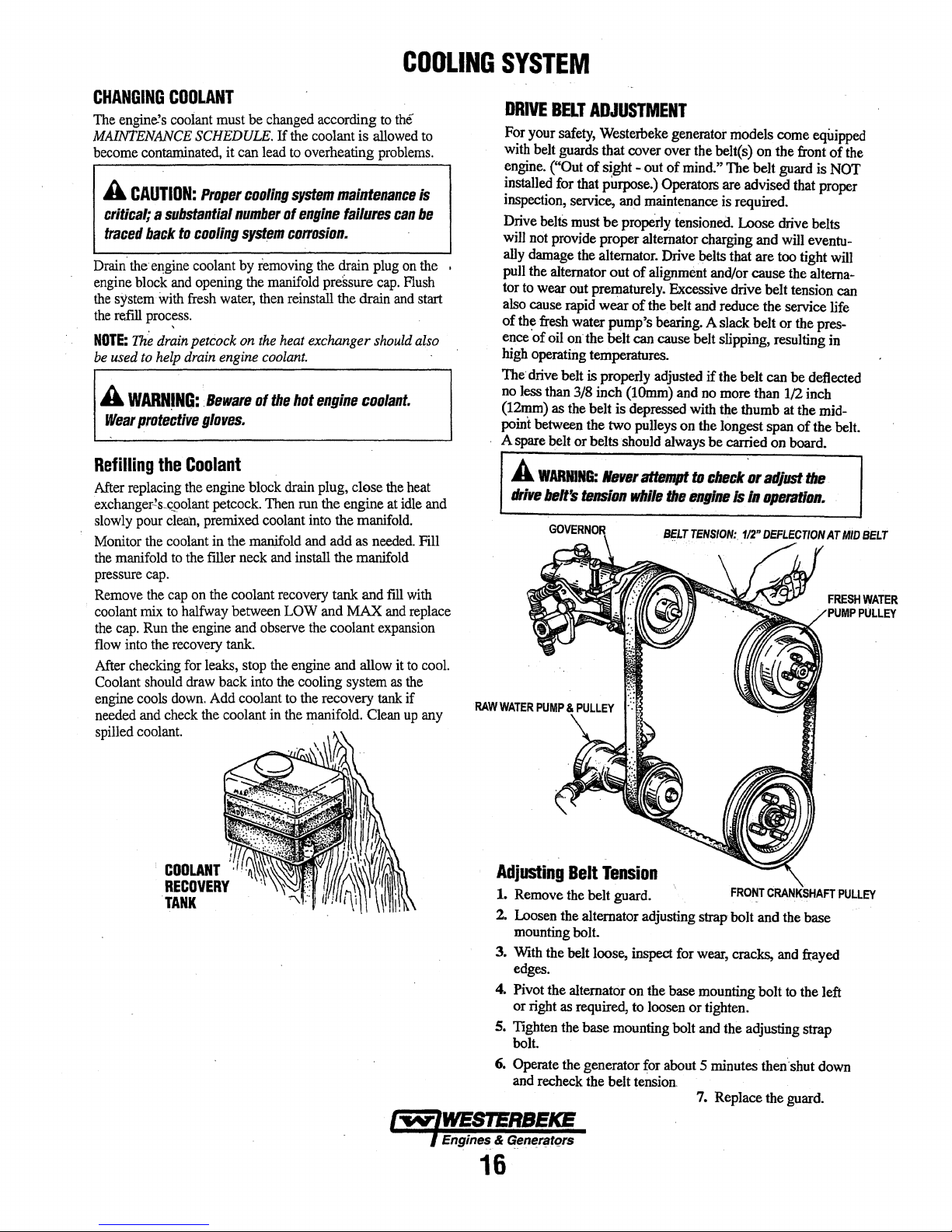
COOLING
SYSTEM
CHANGING
The
engine.'s
MAINTENANCE
become
A
COOLANT
coolant
SCHEDULE.
contaminated,
CAUTION:
Proper
critical; a substantial
traced
back
to
cooling
Drain.
the
e11gine
coolant
engine
block
and
opening
the
system
with
fresh
the
refill
proc~ss.
NOTE:
The
drain
petcock
be
used
to
help
drain
A
WARNJNG:,
Wea1
protective
Refilling
After
exchanger-!s_cgolant
slowly
Monitor
the
pressure
Remove
coolant
the
flow
After
Coolant
engine
needed
spilled
the
replacing
pour
the
manifold
cap.
the
mix
cap.
Run
into
the
checking
should
cools
and
coolant.
BewB1e
glares.
Coolant
the
engine block
petcock.
clean,
premixed coolant
coolant
in the
to
the
filler
cap
on
the
to
halfway
the
engine
recovery
for
leaks,
draw back
down.
Add
check
the
must be
it
can
lead
cooling
numbe1
syst_em
by
removing
the
water,
then
on
the
engine
coolant.
of
manj.fold
neck
coolant
between
and
observe
tank.
stop
into
coolant
coolant in
changed
If
the
coolant is
to
overheating
system
of
engine
according
maintenance
c011asion.
the
manifold
the
Then
and
the
pressure
reinstall
heat
drain
recovery
LOW
the
to
the
the drain
exchanger
hot
engine
plug, close
run
the engine at
into
the
and add as
install the manifold
tank
and MAX
the
coolant
engine
and
cooling
the
recovery
manifold. Cean
to
the
allowed
problems.
failures
~ain
can
plug
cap.
and
should
coolant.
the
manifold.
needed.
and
fill
and
expansion
allow
it
system
as
tank
to
Is
be
on
the
Flush
start
also
heat
idle
Fill
with
replace
to
cool.
the
if
up
any
and
DRIVE
BELT
ADJUSTMENT
For
your
safety,
Weste:rbeke
with
belt
guards that cover over
engine.
("Out of sight - out
installed
inspection,
Drive
will
•
ally
pull
tor
also
of
ence
high
The·
no
(12mm)
point
A
for that purpose.) Operators are advised that
service,
beltS
must
not
provide
damage
the
alternator out of
to
wear out prematurely.
cause
rapid wear
the
fresh
water pump's
'of oil
on
operating temperatures.
drive belt is properly
less than 3/8 inch
as
the
between
spare
belt
A
WARNING:
ddre
.belt's
and
be
properly
proper alternator charging
the alternator.
the belt can cause belt slipping, resulting
belt is
the
two
or belts should
llerer
tension
generator models come
the
of
mind." The belt
maintenance
tensioneO.
Drive
.belts
alignment
Excessive
of
the.
belt
and
bearing.
adjusted
(lOmm)
depressed
pulleys
altBmpt
while
A slack belt or
if
and
no
with
on the longest span of the
always
to
check',,,
the
engine
equipped
belt(s) on the
is
required.
Loose
that are
and/or cause
drive belt tension
reduce
the belt
more
the
thumb at the
be carried on board.
and
the
can
than
front
guard
is
drive
belts
will
eventu-
too
tight
the
altema~
service life
the
be
deflected
1/2
inch
adjusttbe
ls
/11
opntloll.
of
the
NOT
proper
will
can
pres-
in
mid-
belt.
FRESHWATER
PUMP
POLLEY
Adjusting
1.
Remove
2.
Loosen
mounting
3.
With
edges.
4.
Pivot
or right
5.
Tighten
bolt.
6.
Operate
and
Belt
the
the
the
belt
the alternator on
as
the
the
recheck
lwlWESTl!RBEKE
I
Engines_
&
ae~r~tqrs
16
Tension
belt guard.
alternator adjusting strap bolt and
bolt.
loose,
inspect
for
the
base mounting bolt
required, to
base mounting bolt
generator
the belt
loosen
for
about 5 minutes
tension.
FRONT
wear,
cracks,
or tighten.
and
the adjusting strap
7.
Replace
CRANKSHAFT
the
base
and
frayed
to
the left
then'·
shut
down
the
guard.
PULLEY
Page 24

COOLING
SYSTEM
Heat
After
and
pressure test
tive
exchanger).
Exchanger
approximately
radiator
shop
Service
1000
the
engine's
should
ZINC
ANODES
hours
be
able to
of
heat
exchanger.
operation,
clean
and
remove,
(A
local
test
the
clean
automo-
heat
HEAT
EXCHANGER
Cool
raw
water
flows
through
exchanger.
heat
is
then
engine
the
The
other;
hmnful deposits
NOTE:
that a heat exchanger cleaning be peeformed
every
As
the
en~e.
of the internal
pumped
coolant
circuit
repeats
engine coolant
this
keeps
Operating in silty arul/or.tropical waters
1000
into
(now
hours.
engme
the
cooled)
itself.
and
the
engine's water passages clean
found
the
inner tubes of
coolant passes around these
is
conducted to the
exhaust
system
and
discharged.
flows
back though the
raw
water
are
independent of
in
raw
water.
THERMOSTAT
A thermostat controls
continuously
the
engine
coolant
thennostat to
heating).
opens.
cleaned,
gasket.
If
you
bring
is
from
As
The
thermostat
or
replaced
suspect a
to
a
bOil.
flows
first
flowing
prevent
the
started
engine
faulty
A
working
the
coolant temperature
through
the closed cooling circuit.
the
closed
(some
coolant
the
.exhaust
warms
up,
is
accessible
easily.
Carry a spare thennostat
thermostat,
thermostat should
thermostat prevents .
is
by-passed
manifold
the
place it
thennostat
and
can
from
in a pan
raw
may
more
as
be
checked,
open
the
heat
tubes
water
The
engine
each
from
require
often then
the
coolant
When
around
over-
gradually
and
of
water
about
!11e
which
and
the
the
and
112"
..
NEW
ZINC
.
ANODE
A
zinc
anode (or pencil) is located
circuit
within
anode
is
to
in
the
raw
of
electrolysis
dition
of the
anode
cleaned
be
carried
NOTE:
Electrolysis
and vessel location, not that
If
the
zinc
which
the
loosening
hex
boss
from
removing
poor
condition,
the
exchanger.
clean
the
inside
exchanger
damaged
(refer
number),
NOTE:
not
insulate
housing preventing electrolysis action on the
when
to
your engine model's
0-ring
The threads
require
the
THROWOUT
the heat
sacrifice itself to electrolysis
water
zinc
onboard.
anodes
zinc
the:
anode
the zinc, note the condition of it.
end gasket
sealant. Sealant should not be used as it
zinc from
exchanger.
cooling
on other
or
anode
possibly tearing off the exchanger
there
Remove
of
removing
circuit,
components
anode
should
replaced,
is
need
all
and
of
as
the
r.esult
replacement,
is·
threaded
with
another
are
probably
the end of the heat
zinc
debris.
in
case
the end
cover,
the
zinc anodes are pipe
the
metal
THROWOUT
in
the
raw
water
The
purpose
thereby
of
be
checked
required.
of
each particular installation
of
the
engine.
hold
with a wrench
wrench.
alot
Al.ways
the
present one
cover.
heat
exchanger
and
install a new
of
the
heat exchanger
of
action
taking
reducing
the
system.
monthly
Spare
anodes
the
hex
This prevents
If
the
of
zinc
flakes
exchanger
have a spare
becomes
Replace
end
zinc
threads
zinc.
CLEAN
REUSE.
cooling
the
zinc
place
the
effects
The
con-
and
should
boss
into
while
shell.
After
zinc
is
within
and
heat
the gasket
gasket part
anode.
and do
may
AND
the
the
in
THERMOSTAT
ASSEMBLY
IW'IWESTERBEKE
.f Engines & Generators
.
-17
Page 25

FUEL
SYSTEM
GASOLINE
Use
u.nkatied
follow
companionways
ventilate
NOTE:
fume
detector/ala.rm
AWARNING:
When
Ing
any
Ing,
fuel
system
tion
GASOLINE/WATER
A primary
installed
water
and
be carried
Most installers include a type of filter/water
the generator installation package
the problems that contaminants in the
These gasoline filters must
through")
bowls
have
impurities. · ·
89
octane
or
higher
gasoline.
U.S.
Coast
Gtiard
regtilations,
to
prevent
fuines
ii:om
after
fueling.
The
generator
servicing
fae/tbat
011110
flames
exists
when
. . .
fuel
between
other
to
the
to
meet
drain
compartment
properly
Shat
o"
the
tael
may
spill.
or
other
wbell
servicing.
servicing
SEPARATOR
filter
of
the
the
fuel
tank
conUllillnants
fuelsystem
U.S.
Coast0u$l
-valves
to
should
installed
the
fuel
system.
DO
Take
NOT
SOUICllS
Ensure
the
fuel qstem.
water separating type must
and
the.
from the
on
the
en~e,;
as
have
metal
requirements.
use
when checking for
When
fueling,
close off
valve
of lire
AND
they are
all
hatches
entering
and
allow
proper
the
boat,
have a gasoUne
working.
at
the
tank
care
in
catch·
anysmok·
near
the
ventila·
FILTER
engine
to.
remove
~elbefore
fuel
cari
bowls
they
·
sep~tor
:Well.
aware
·cause:
(not
"see•
The
water
and
and
be
cari
with
of
Jn.eta}
and
GASDENSER
The
gasdenser consists
coiled around the raw water intake line
located between the raw water intake
pump.
The
gnsdenser
lock.
12V
CONNECTION
FUEL
CONNECTION
.
FUEL
LIFT
PUMP
Periodically check
and
make
sure
that
and
are tight
pump's
the
mounting bolt
The
engine
secure.
mounting
mounted
of
a portion
cools
:..l'
[Ii
I
bolts should be clean
to
. _,,..
11
FUEL
TO
MOUNTING
the
fuel
connections
no
leakeage
The
DC
ensure proper pump
fuel
lift
of
the fuel line that is
and
insulated. It
and
the raw water
the fuel to help prevem vapor
CARS
"
FUEL
LIFT
PUMP
BOLT
to
and
out of
the
is
present
ground
pump
and
thatthe fittings
connection
and
is
~ain1enance
at
one
well
~e9ured
operation.
free.
of the
i»
puJN)
by
GASOUNE/WA'FER
SEPERATOR & FILTER
A
WARNING:
connections
Make.sure
faelsyst.em
proper
CARBURETOR
This generator has just
carburetor.
·
shown.
screen
To
Clean
should
lw/WESTERSEKE
~rutlne.s.,S
Generators
18
Fuel
leakage
Is
a lire
hazard
ventilation
components.
FILTER
remove
the
be cleaned
filter
SCREEN
one
filter
the
filter
screen
periodically.
and
exists
screen
screen,
or,
if
at
the
should
~
unscrew
needed,
fuel
pump
be
corrected.
whenever
that
is
located in
the plug
replace it. This
or
Its
servicing
the
as
Page 26
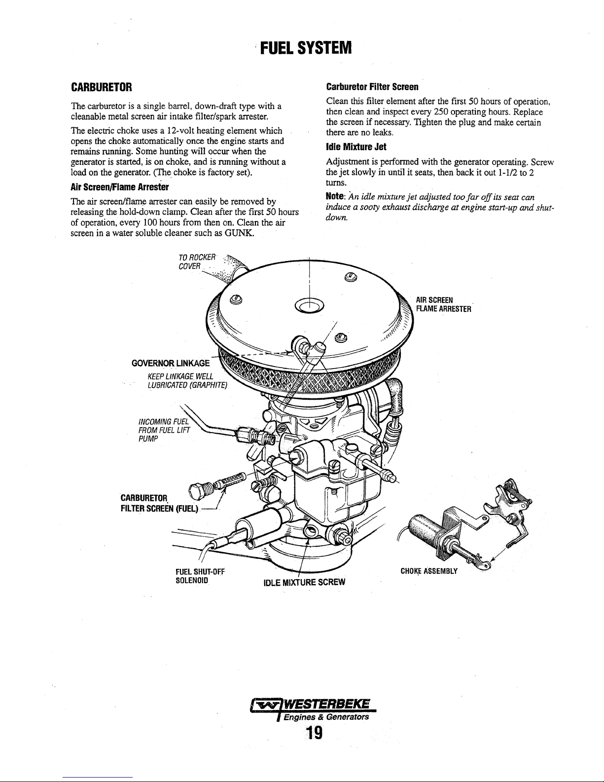
;
FUEL
SYSTEM
CARBURETOR
The
carburetor
cleanable
The
electric
opens
the
remains
generator
load
ori
Air
ScreenJFlame
The air
releasing
of
operation,
screen
in
is a single
metal
sereen
choke
uses
choke
automatically
running.
the
is
started,
generator.
Some
Arrester
screen/flami;:
the
hold-down
every
100
a water
soluble
air
a 12-volt heating element
hunting
is
on
<ne. choke
arrester can
clamp.
hours
barrel,
intake
once
choke,
from
cleaner
down-draft
filter/spark
the
engine starts
will
occur
and
is
running
is
factory
easily
be
Clean
after
then
such
as
type
arrester.
when
set).
removed
the
on.
Clean
GUNK.
with
which
and
the
without a
by
first
SO
the
air
a
hours
I
©
Carburetor
Clean
then
the
there
Idle
Adjustment
the
jet
turns.
Note:
induce a sooty
this
clean
screen
if
are
no
Mixture
slowly
An
idle
Filter
filter
and
is
down.
Screen
element
inspect
necessary.
leaks.
Jet
performed
in
until
mixture
exhaust
after
the
every
250
Tighten
with
the
it
seats,
then
jet adjusted
discharge
first
50
operating
the
plug
generator
back
too
far off
at
engine
hours
and
it
out
start-up
hours.
of
operation,
Replace
make
certain
operating.
1-112
to
its
seat
can
and
Screw
2
shut-
·,
;'
IDLE
MIXTURE
SCREW
Engines & Generators
19
Page 27

ENGINE
OIL
CHANGE
Engine
1. Draining the Oil Sump. Discharge the used
WARM
THE
SUITABLE
Always observe
yellow/gray emulsion indicates the presence
the oil. Although this condition is
prompt attention
petent"
water present in the oil can
exhaust system attached
of
caused by the poor location of or the lack
2.
NOTE:
to make certain it
·(Oil
Oil
Change
oil
drain
hose
the sump
while the engine is
replace the hose
securel_y.
THE
ENGINE.
OIL
INTO
A
CONTAINER
mechanic should water be present in the oil.
raw water through the raw water cooling circuit into
the exhaust,
siehon
Replacement
oil filter, you
hole in the upper and lower portion
drain the oil
This helps to lessen spillage. A small style automotive
ter wrench should be helpful in removing the old oil
Do
Place some paper towels and a plastic bag around the
ter when unscrewing
cooling ability.
old oil filter as it
sealing gasket came off with the old oil filter.
ber sealing gasket remains sealed against the engine
block, gently remove it.
When installing the
gasket's sealing surface on the engine block free
apply a thin coat of clean engine oil to the rubber gasket
on the new oil
filter nipple, and then tighten the filter firmly
:filling
valve.
may
from
not punch this
or
any other
(attached
warm.
in
its bracket,
SHUTDOWN
of
can
filter.
AND
the
used
to
prevent serious damage. Call a
the engine. This problem is often
the Oil Filter. When removing the
find
it
it into a container before removing it.
hole
be
removed!
it
to catch any oil left
fluid
on the engine reduces the engine's
Please keep your engine clean.) Inspect the
is
removed to make sure that the rubber
new
Screw the filter onto the threaded oil
to
the front
Drain
the used
and
DRAIN
.
oil as it is removed. A
rare,
be
the result
to
the engine and/or a siphoning
helpful and cleaner
of
without first loosening the filter
oil filter element, wipe the filter
of
the
oil
completely,
replace the end cap
of
water
it does require
of
a fault
of
an
to
punch a
tbe old filter to
in
the
If
~y
through
en!iine)
com-
Raw
in
the
anti-
u~
filter.
filter.
this rub-
of
oil
hand
in
fil-
fil-
and
3.
Fi16ng
the
Oil Sump.
cap on the top of the engine or through the side oil fill.
After refilling, run the generator for a
checking the engine's oil pressure. Make sure there is no
leakage around the new
tem,
and stop the generator. Then check the quantity
with
the lube oil dipstick.
mark on the dipstick, should the engine require
Add
oil
SEALING
APPLY
CLEAN
.
WHEN
ASSEMBLING
NEWRLTER
new
oil through the oil filler
few moments while
filter
or from the oil drain sys-
Fill
to,
but
not
over the high
GASKET
OIL
additionalo_it.
SPIN-ON
TURN
HAND
NOTE:
Generic filters
standards
mi.ght
after
sure
around
A
or diameters
be
entirely different
an
oil filter change
the
oil pressure is normal
the
new
WARNING:
contaminants.
and
aails
thoroaghly
distanl
used
Oil
The engine's oil pressure, during operation,
the
mal
psi.
NOTE:
reading
pressure reading as low
depending upon the
placed
clothing
oil
ptopetly.
Pressure
oil
pressure gauge on the instrument panel. During
operation, the oil pressure will range between 35 and
A newly started,
upwards
on
the
are
oil
filter.
Used
Avoid
or
rags
of
60 psi. A
temperature
generator.
not
recommended,
of
important items on generic parts
from
genuine parts. Immediately
and
oil
fill,
run
and
that there
engine
on
t:llllfains
/lfO/Dllgell
using
soap
skin
and
IJfllltaining
cold
engine
can
warmed
as
35
psi.
These
of
the
as
the
material
the engine to make ·
are
no oil leaks
bannful
contact.
watet.
llSlld
have
engine
engine and the load
Clean
l.allndet
ail.
Dist:artl
is
indicated
an
oil pressure
can
have an oil
readings will vary
of
OIL
FILTER
skin
or
by
nor-
oil
ENGINE
BLOCK
TIGHT
55
,,...,.,WESTERBEICE
Engines & Generators
20
Page 28

INSTALLATION
This
popular
ter
from
engine
NOTE:
instructions
To
install,
WBSTERBEKB's
install
Cont.act
accessory
the
engine
room
bulkhead.
Refer
to
ENGINE
on
simply
this
kit
with
your
WESTERBBKE
to a more
removing
remove
remote
the
is
OIL
the
oil
used
to
convenient
CHANGE
oll
the
engine
oil
filter kit
filter
dealer
REMOTE
relocate
filter.
facing
oil
as
down
for
the
engine's
location
in
this
filter
and thread
shown.
as
more
nu.mual
Always
illustrated.
information.
OIL
PN.
oil
such
as
for
FILTER'(OPTION_AL)
040078
Nm:
on
til-
an
Westerbeke
incorrect
installation
A
CAUTION:
rsattr.
If
pass
valvll
frtllll·~
falln.
-
lmmedialllly
thB
oil flows
In
tile
If
ttlel'S
aad.t:het:k
is
notresponsible
of
the
Remote
It
is
vital
In
t/IB
mter:
ll$Sllllbty
tile
••n•
Is
no
oitpnis$1frs
tllfl
for
Oil
Filter.
to
Install
tbs
,,_,..
will
t:a~t1111
a1Jtnt11111a1111g1n1
,.,.,,,,,,,
bOStJ
OOIHlflDtlOllS.
engine
fail1.1re
on
111111$
dilllDtlon,
pnw1111t
tbs
$hufd0wn.
cor-
tile
all
due
by·
to
APPLY A lHIN
INSTALLING
TIGHTEN
AN
CONTACTS
THEGUrCONNECTIONHOSE
MUST
ATTACH
TO
THE
CONNECTION
REMOTE
OIL
AT
THE
FILTER.
IN
COAT
OF
THIS
THE~
CLEAN
KIT.
THRWI
ADDmONAL
3/4
OIL
TO
THE
TURN
lllE
KIT
ON,
AFTER
IHllNG
1llEH
THE
0-RING
WHEN
~
APPLY A THIN
GASKET
WHEN
CQ.NTACTS
THE
CO~
OF
CLEAN
INSTALLING.
BASE.
l\FTER
TIGHTEN
OIL
TD
lRE
lRE
ALTER
IT
AN
ADDITIONAL·
FILTER
Engines & Generators
21
Page 29
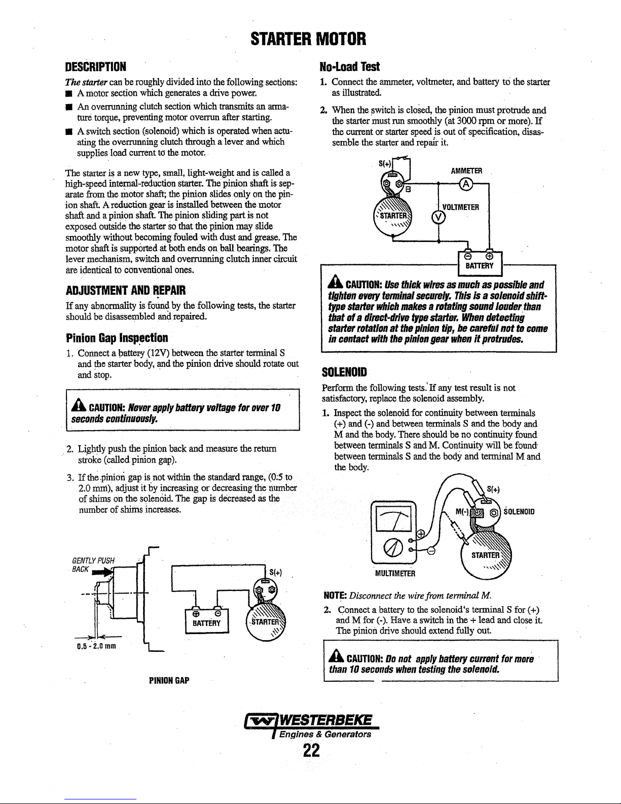
STARTER
MOTOR
DESCRIPTION
The
starter
can
be
roughly
divided into
• A
motor
section
which
generates a drive
•
An
overrunning
ture
torque,
• A
switch
ating
the overrunning
supplies
The
starter
is a new
high-speed internal-reduction
arate
from
the
ion
shaft.
A reduction
shaft
and
a pinion
exposed outside the
smoothly
motor shaft
lever
are identical
ADJUSTMENT
If
should
Pinion
1.
A
secandS
2.
.·
3.
without
mechanism,
. .
any
abnormality
be
disassembled
Gap
Connect
and
the
starter
and
stop.
CAUTION:
continuously.
Lightly
push the
stroke (called pinion
Ifth~.pinioii
2.0
mni), adjust
of
shims
number
clutch
section
preventing
section
load current
motor
is
supported
to
conventional
AND
motor
(solenoid)
clutch
to
type,
small,
shaft;
gear
shaft.
The
starter
becoming
at
switch
and
REPAIR
is
found
and
lnsp~ctlon
a pattery (12V) between
body,
and
Never.apply
pinion
gap).
gapis not
it
by
increasing or decreasing the
on
the
Solenoid.
of
shims
increases.
the
following
power.
which transmits
overrun after
which
is
operated
through a lever
the
motor.
light-weight
starter.
The
pinion shaft
the
pinion
slides
only
is
installed
pinion sliding part
so
thatthe pinion may slide
fouled
both
overrunning clutch inner circuit
ones.
by
repaired.
the
battery
back
within
The
between
with dust and
ends
on
ball
the following
the
starter terminal S
pinion drive should
voltage
an.d
measure the
the standard range,
gap
is
decreased
an
starting.
when
and
which
and
is
called
on
the
motor
is
not
grease.
bearings.
tests,
the
rotate
for
over
return
as
sections:
arma-
is
the
(0;5
number
the
actu-
a
sep-
pin-
The
The
starter
out
10
to
No-Load
1.
2.
Connect
as
illustrated.
When
the
starter
the
current
semble
Test
the
ammeter,
the
~witch
is
must
run
or
starter
the
starter
.--------------1
A
CAUTION:
tighten
type
starter
that
of.a
starter
in
contact
Use
11very
tllflllinal
Which
direct-drive
rotation
with
at
the
SOLENOID
Perform
satisfactory,
1. Inspect the solenoid
the
( +)
and
M and
between
between
the
body.
following
replace
(
~)
and
between
the
body.
There should be
terminals S and
terminals S and
voltmeter,
closed,
smoothly
speed
and
repa1r
thick
wires
securely.
makes a rotating
type
the
pinion
pinion
tests.'
the
solenoid
for
continuity between terminals
terminals
and
battery
the
pinion must protrude and
(at 3000 rpm
is
out of specification,
it.
e
BATTERY
as
much
This
is a solenoid
sound
starter.
gear
If
M.
the
When
tip,
be
careful
when
It
any
test result is
assembly.
S and the
no
continuity
Continuity will
body
and terminal M
to
the starter
or
more).
disas-
""
as
possible
louder.than
detecting
not
ta
ptatrudes.
not
body
found
be
found·
If
and
shift·
came
and
and
D.5··2.omm
PINION
GAP
NOTE:
Disconnect
2.
Connect a
and M for (-).
The pinion
A
CAUTION:
than
10
seconds
Engines & Generators
22
MULTIMETER
the
wire
battery
to
the
Have a switch
drive
should
Oa
not
apply
when
testing
from
terminal
solenoid's terminal S
in
extend
battery
the
M.
the
+ lead and
fully
out
current
solenoid.
far
for
( +)
close
more
it.
.
Page 30

ATTRACTION
3.
TEST
Holding
minal
S ( +)
pinion
Y'hen
released
fully~
test.
@
BAliERY
With
and
to
The
pinion
from
a
battery
the
starter
holding
cionnected
must
with
body,
manually
re1)1aitJ.
your
STARTER
to
the solenoid
pull
out
atthat position
hand.
ter-
the
even
MO'fOR
4.
.
Return
minal
pinion
when
test:.
M
(-)
and
fully.
The
released
With
a battery
to
pinion must
from
the
starter
holding
connected
body,
manually
return
by
hand.
to"the
solenoid
·pull
out the
to
its original position
ter-
HOLDING
· 5.
TEST
STARTER
1.
DisconI1e~t
2.
Loosen
·
the
3.
Remove
fastening
4.
With
remove
the
Remove
washer;
6.
Unscrew
same
adjustment will
DISASSEMBLY
the
wire"
the
two
screws.
solenoid
armature
assembly.
the
t:Wo
long
the brush
the brushes pulled awayfrom
the
yoke
oul
the
cover,
the boltsand removethe center pracket.At
time,
the
washers
come
from
the solenoid
fastening
through
holder.
Remove
and
brush
pry
the snap ringqut,
for
the pinion shaft end play
off.
INSPECT
WEAR & CHIPPING
bolts
holder
FOR
termin&l
the
solenoid.
and
two screws
the rear bracket.
the
armature,
assembly.
Then
·
and
M (-
).
Remove
pull
remove the
the
7.
Pull
front
8.
On
pinion
9.
At
a
bearing
press-fitted
off,
out
the
bracket.
the
pinion
and
pinion
each
end
puller.
replace
SOLENOID
RETURN
reduction
side, pry
shaft. ·
of
the
armature,
It is impossible
in
the front
the front
gear
the
bracket.
bracket
TEST
lever
and
snap
ring
remove
to
If
assembly.
lever
out,
the
replace
_that
spring
and
ba11
the
bearing
from.
pull
out the
bearing
ball
bearing
has
worn
the
with
STAllTER
MOTOR
PINION
SHAF"f
. ,EngiM
23
..
i(&
Generators
;
.•
\ .
. ' .
"------··
NOTE:
lnspect,
if
necessary
solenoid,
following
, .
clean
brnsh,
armature,
pages.
commuter,
etc.
and
replace
See
the
Page 31

BATTERY
CHARGING
CIRCUIT
The DC Circuit on the
stop the generator's engine. The circuit is best understood
reviewing the DC Wiring Diagram and Wrring Schematic.
Tue engine's DC wiring is designed with three simple basic
circuits: start, run and stop.
The engine has a 12 volt DC electrical control
shown on the
when troubleshooting or when servicing the DC electrical
system or the engine.
Wrring Diagrams. Refer to these diagrams
BCG
functions to start, operate and
by
circuit that is
BATTERIES
A
CAUTION:
ing
circut,
while
the
switch,
ing
however,
on
the
To
never
shut
engine
is
engine's
avoid
off
running.
to
avoid
electrical
damage
the
engine
Shut
electrical
circuit.
to
the
battery
off
the
shorts
battery
switch
engine
when
charg-
battery
work·
Specificatfons
The minimum recommended capacity .of the battery used in
the engine's 12-volt
BATTERY
The generator supplies a continuous 10 amp charge from its
battery charger
charger put a multimeter between the positive ( +) and
negative (-) leads to the battery. It should indicate
14V with the engine running.
indicated, check
are tight. With the unit running, test between the (
terminals
the charger.
CHARGER
f0r..B.5V to
DC
control circuit is
to
the starting battery.
If
that
the battery charger terminal connections
14V.
If
no charge is igdicated, replace
400
CCA.
To
test the battery
only .the battery voltage is
13.SV
.to
+) and (-)
Battery
Review the manufacturer's recommendations and then establish a systematic maintenance schedule for your engine's
starting batteries and house batteries.
• Monitor your voltmeter for proper charging during engine
• Check the electrolyte level and specific gravity with a
• Use only distilled water to bring electrolytes to a proper
•
• Keep your batteries clean and free
A
cause
protective
"-
Maintenance
operation.
hydrometer.
level.
Make certain that battery cable connections are clean and
tight
to
the battery posts (and to your engine).
of
corrosion.
WARNING:
severe
bums
gear.
Sulfuric
on
skin
acid
and
in
lead
damage
batteries
clothing.
can
Wear
NOTE:
FOR
(INTEGRAL
THE
DESCRIPTION
CONTROLLER),
REFER
AND
TO
TESTING
THE
FOLLOWING
OF
THE
BATTERY
PAGE.
CHARGEN
Engines &
24
GeneratoL~
Page 32

BATIERY
CHARGING
CIRCUIT
INTEGRAL
The
Integral Controller (l.C.) is an encapsulated, solid-state
that supplies a
unit
starting battery while the generator is opening.
Charging Voltage: 13.0 - 14.0
Charging Amperage: 0
A separate group of stator windings supplies AC voltage to a
bridge rectifier
LC.
unit The
and supplies a
that the I.C. unit is faulty (that is,
low), check the
described in the following steps. Check all connections for
cleanliness and tightness including the ground before replacing
the
J.C.
NOTE:
produce
the generator
The
Integral Controller is mounted inside the generator housing in the
on
the controller that will allow a DC voltage output adjust-
ment of:± 2 volts.
NOTE:
circuit
internally.
the
~er
CONTROLLER
DC
which converts the AC current to supply the
I.C.
unit senses the needs
DC
charge when one is needed
charging circuit
unit.
When
the generator
a low
charging
is
operated.
12:00
position. There is a voltage output adjustment
New
four
wire
since
the ballast resistor's function is now handled
Whenever
four
wire
mode~
(J.C.)
charging voltage to
volt.$
-10.0
amps DC
if
the
and
it's components
is
first
started,
rate.
This
charging
controllers
replacing
eliminate
an
early stylr controller with
remove
the ballast
the
DC
of
the starting battery
battery's charge is
the
rate
the ballast
generator's
..
If
you
_suspect
as
LC.
unit will
will
rise
resistor
as
resistor
and
its
wiring.
BRIDGE
RECTIFIER
YELLOW/WHITE
POSl!/VE(+)
TERMINAL
INTEGRAL
.
~ON)'RDlLER
OF
RECTIFIER
GROUND
GENERATOR
TO
Testing.
1.
the
Battery
Charging
Bridge Rectifier
Normal
eng1ne
two
illustrated).
AC voltage running
AC
voltage running
is operating at 1800 rpm)
AC connections on the bridge rectifier. (As
to
the bridge rectifier (approximate):
No-load off the generator 16.0 volts AC
Full-load off the generator
Normal
DC)
bridge rectifier; that is
DC voltage running from the bridge rectifier
(approximate):
DC voltage running out
is measured across the two
+ and
No-load off the generator 17.0 volts DC
Full-load off the generator
2. AC winding:
Lift the
measure, the resistance between these
ohmmeter. It should measure
should exist between
the main AC stator windings.
0.10.
ohm
two
AC wire leads off the bridge rectifier and
these
3. Testing the Bridge Rectifier (meter
a. Set your ohmmeter's scale on
needle to zero.
CASE
b. Connect the (
point #4. Taking the
momentarily touch poirits #1,
meter should register
points touched.
c.
Remove the positive { +) lead from point
connect the negative (-) lead; momentarily touch
points #1,
deflect when each point is touched.
d. Leaving the negative ohmmeter(-) lead
- touch point #5 with the positive lead. No deflection
should
e. Place the positive (+)lead on point
(-)lead on point #3. The ohmmeter again should not
register any deflection (no deflection indicated
resistance). Reverse these connections and the ohmmeter should again register
fails any
fier because it is defective.
NOTE:
Different
produce
oppositP
+)
positive lead from the ohmmeter
o~eter's
#2, and #3. The ohmmeter's needle should
take place.
of
the previous tests (A-E), replace the recti-
types
and/or
test
results.
Circuit
to
the rectifier (while the
is
measured across the
17.5
volts AC
of
the rectifier
DC
connections of the
-.
. 18.5 volts DC
two leads
O.lQ
ohm.
two leads and the ground or
used
RXl
(+DC)
negative(-) lead,
#2, #3, and #5.
no
deflection for any
#1
no
deflection.
brands
of
test
(in
with
No continuity
- Simpson
and set the
The
of
#4
and
on
point #4,
and the negative
If
the rectifier
meters
may
volts
an
260)
to
ohm-
the
infinite
.
iNiEGRAL
CONTROLLER
POINTl4
.
BRIDGE·
RECTIFIER
POINTl3
POINTIS
MOUNTING
HOLE
Page 33
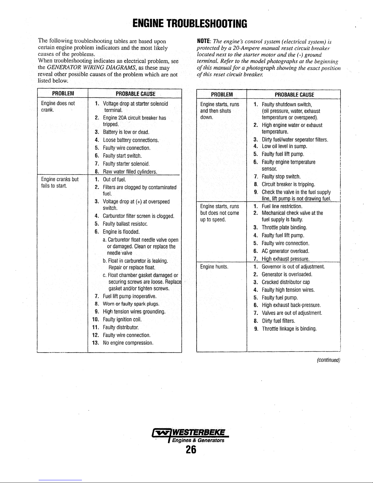
The
following
troubleshooting
tables
certain engine problem indicators
causes of
When
the
reveal other
the
problems;
troublesbooting indicates
GENERATOR
WIRING
posSible
caus~
DIAGRAM.S,
of the problem
listed below.
ENGINE··
are
based upon
and
the
most
an
electrical problem,
as
these
which
TROUBLESHOOTING
NOTE:
The
engine
3'
control
likely
may
are
see
not
protected by a 20-Ampere manual
located
terminal. Refer to
of
of
next to the starter motor and
t/1£
model photographs at
this
manual for a photograph showing
this.
reset circuit
breaker:
sy.vtem
(electrical system)
reset
circuit breaker
the
(-)
ground
the
the
exact position
is
beginning
Engine
crank.
Engine
fails
'-----
PROBLEM
does
not
cranks
but
to
start.
1.
Voltage
terminal.
2.
Engine
tripped,
3.
Battery
4.
Loose
5.
Faulty
6.
Faulty
7.
Faulty
8.
Raw·
1.
Out
2.
Filters
fuel.
3.
Voltage
switch.
4.
Carburetor
5.
Faulty
6.
Engine
a.
b.
c.
7.
Fuel
Worn
8.
9.
Higti
10.
Faulty
11.
Fiiulty
12.
Faulty
No
13.
PROBABLE
drop
at
20A
circuit
·"
is
low
battery
wire
connection.
start
switch.
starter
solenoid.
water
filled
of
fuel.
are
clogged.
drop
at(+)
filter
ballast
resistor.
is
flooded.
Carburetor
or
damaged.
needle'
Float
Repair
Float
securing
gasket
engine
float
valve
in
carburetor
or
replace
chamber
screws
and/or
lift
pump
or
faulty
tension
wires
ignition
distributor.
wire
connection.
compression.
CAUSE
starter
solenoid
breaker
has
or
dead.
connections.
JMinders.
by
contaminated
at
overspeed
screen
is
clogged.
needle
valve
Clean
or
replace
is
leaking.
float.
gasket
damaged
are
loose.
tighten
screws;
inoperative.
spark.plugs.
grounding.
coil.
open
the
or
Replace
PROBLEM
Engine
starts,
and
then
down.
Engine
starts,
but
does
up
to
speed.
Engine
hunts.
shuts
not
come
runs
runs
1.
Faulty
(oil
pressure,
temperature
2.
High
engine
temperature.
3.
Diny
fuel/water
4.
Low
oil
5.
Faulty
6.
Faulty
sensor.
7.
Faulty
8.
Cirt::uit
9.
Check
line
J!!tp_umit
Fuel
1.
2.
3.
4.
5.
6.
7.
1.
2.
3.
4.
5.
6.
7.
8.
line
Mechanical
fuel
supply
Throttle
Faulty
Faulty
AC
generator
Hj[h
Governor
Generator
Cracked
Faulty
Faulty
High
Valves
Dirty
Throttle
9.
exha.ust.Q.ressure.
exhaust
fuel
PROBABLE
shutdown
level
fuel
engine
stop
breaker
the
restriction.
plate
fuel
wire
distributor
high
fuel
are
linkage
CAUSE
switch,
water,
exhaust
or
overspeed).
water
or
separator
in
sump.
llft
pump.
temperature
switch.
is
tripping.
valve
in
the
is
not
drawino
check
valve
ls
faulty.
binding.
lift
pump.
connection.
overload.
is
out
of
adjustment.
is
overloaded.
cap
tension
wires.
pump.
back-pressure.
out
of
adjustment.
filters.
is
binding.
exhaust
filters.
fuel
supply
at
the
(contlntJed}
fuel.
(
!
l
I
!
.)
·Engines
26
&
Generators
Page 34

EftGINE
TROUBLESHOOTING
PROBLEM
Engine
Engine
Engine
Low
oil
misfires.
backfires.
overheats.
pressure.
1.
Poor
Incorrect
2.
3.
Dirty
4.
Cracked
5.
Faulty
Spark
6.
7.
High
a.
Valve
Spark
1.
wrong.
2.
Incorrect
3.
Engine
flooded
to
start
Dirty
4.
5.
Cracked
6.
High
7.
Choke
1.
Coolant
cooling
2.
Faulty
3.
Belts
Raw
4.
Faulty
5.
6.
Heat
Collasped
7.
1.
Low
Wrong
2.
3..
Wrong
4.
Relief
Faulty
5.
Faulty
6.
Faulty
7.
PROBABLE
quality
fuel.
timing.
flame
arrester.
distributor
ignition
wires.
plugs
are
worn.
exhaust
back~pressure.
clearances
plug
is
under
flame
exhaust
is
loss.
system.
raw
are
water
thermostat.
exchanger
oil
level.
SAE
type
valve
oil
engine
oil
are
wires
timing.
flooded.
Engine
arrester.
distributor
back-pressure.
stuck
closed.
Pressure
water
pump
loose
or
pump
is
hose.
type
oil
oil
filter.
is
stuck.
pump.
bearings.
filter.
CAUSE
cap.
inoom~ct.
are
connected
See
Engine
is
cranks
but
tails
cap.
test
impeller.
broken.
worn.
clogged.
in
the
engine.
PROBLEM
High
oil
pressure.
No
DC
charge
starting
battery.
Blue
exhaust
discharge
engine.
Black
diseharge
engine.
from
exhaust
from
to
the
smoke
the
smoke
the
1.
Dirty
Qi!
engine.
2.
Relief
1.
Faulty
2.
Faulty
3.
Faulty
windings.
4.
Connections
loose
5.
Faulty
1.
Lube
oil
2.
High
lube
3.
Crankcase
4.
Valves
incorrectly.
5.
Piston
or
unseated.
1.
Dirty
flame
2.
Faulty
3.
Idle
mixture
4.
Valves
adjusted.
5.
Lube
oil
6.
Piston
7.
Crankcase
PROBABLE
or
valve
connections.
bridge
generator
or
faulty.
controller.
is
are
rings
carburetor.
are
is
rings
CAUSE
wrong
is
stuck.
rectifier.
charger
to
the
diluted.
oil
level.
breather
worn
or
are
worn
arrester.
jet
too
worn
or
diluted.
are
worn
breather
SAE
controller
adjusted
rich.
incorrectly
type
hose
or
unseated.
hose
oil
in
are
is
clogged.
is
clogged.
the
Engines & Generators
27
Page 35

ENGINE
NOTE:
WESTERBEKE recommends
be
adjustments
The
information below is provided
perfonned by a competent engine mechanic.
ADJUSTMENTS
that
the
following engine
to
assist the mechanic.
ENGINE
SPEED
(HERTZ)
ADJUSTMENT
Governor
The
belt-driven, mechanically operated governor maintains
the engine's rpm under various load conditions. Engine speed
determines the hertz and voltage output
Governor
Operate the generator to bring the unit up to operating
temperature before adjusting the governor.
NOTE:
adjust the linkage at no-load
before proceeding with the adjustment.
There are three adjusting points on the governor
(see illustration).
1.
Increase/Decrease
sets the no-load speed
between the governor arm and throttle lever should be
adjusted to hold the throttle full open when the engine is
not running.) Make sure
that the ball joint connectors are properly lubricated.
graphite lube for this purpose. Disconnect the ball joint
and apply graphite lube
Adjustments
If
the governor
is
severely out
to
obtain a safe output voltage
Speed Adjustment. This adjusting bolt
of
the engine. (The linkage
this linkage moves freely and
to
the inside
2. Hunting/Regulation Aqjustment.
engine speed between no-load and full-load is too great,
adjust this eye bolt to draw the spring closer
hub. The increase/decrease speed bolt may need
adjusted as well.
If
the governor surges under load, adjust this eye bolt to
the
move
adjustment).
3. Bumper
a no-load surge
into the governor so far that it increases the no-load speed.
spring away from the lever hub (check speed
Screw
Aqjustment. This screw is used to remove
ONLY.
NEVER tum the bumper screw
of
the generator.
of
adjustment, manually
arm
of
the joint.
If
the variation in
to
the lever
to
Use
be
Governor
·
1.
2. Governor Oil Capacity: 3 ounces SAE IOW/30 oil.
3.
KEEP
LINKAGE
WELL
LUBRICATED
THRO
TILE
LEVER
HUNTING
REGULATION
ADJUSTMENT
Maintenance
Periodically lubricate the linkage arm attaching points at
the governor
lubricant
NOTE:
proper governor/throttle operation.
(Synthetic oil
NOTE:
To
change the oil, remove the oil
container
drain
Allow the oil to completely drain. Replace the governor
drain plug. Then remove the
located on the back
with three ounces
out
of
plug and the oil
LINKAGE
arm and throttle lever. Use a graphite
or
equivalent.
Free
movement
is
Do not
overfiJl
tinder the governor and remove
plug.
the oil
fill
ARM
.
INCREASE/DECREASE
SPEED
ADJUSTMENT
of
this linkage ann is important for
recommended)
the
governor.
fill
alle~
of
the governor. Fill the governor
of
oil
or
more until oil
level opening. Replace the allen head
fill
plug.
plug. Place a small
head oil fill level plug
·starts
the
governor
to flow
4.
Periodically adjust the governor belt tension (see DRIVE
BELT
ADJUSTMENTS). Since belts stretch slightly, this
stretching will, to some degree, affect the governor's
action.
Engines & Generators
28
Page 36
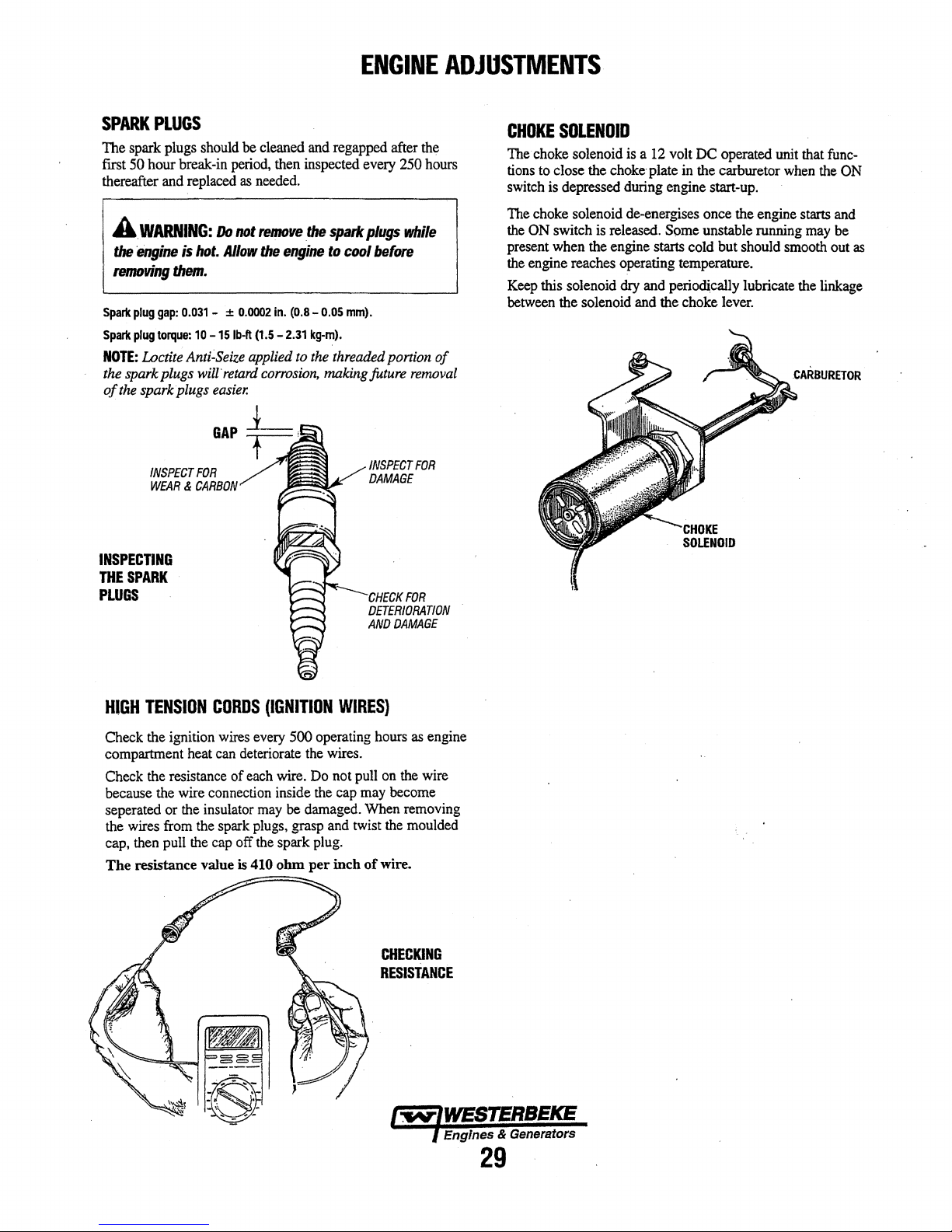
ENGINE
ADJUSTMENTS
SPARK
The
first 50
thereafter and replaced
Spark
Spark
NOTE:
the
of
PLUGS
spark plugs should
hour
break-in period, then inspected every 250 hours
AWARNING:
the
engine
is
hot.
removing
spark plugs
the
them.
plug
gap:
0.031 - :!: 0.0002
plug
torque:
10
Loctite Anti-Seize applied to the threaded portion
spark plugs
-15
wilt
easier.
be
cleaned and regapped after the
as
needed.
Do
not
Allow
lb-ft
retard
remove
(1.5 - 2.31
the
the
engine
in.
(0.8 - 0.05
corrosion,
spark
to
kg-m).
making future
GAP
INSPECT
FOR
WEAR & CARBON
INSPECTING
THE
SPARK
PLUGS
plugs
while
cool
before
mm).
removal
INSPECT
DAMAGE
,______CHECK
FOR
DETERIORATION
AND
DAMAGE
FOR
of
CHOKE
The choke solenoid is a 12 volt
tions to close the
switch is depressed during engine start-up.
The choke solenoid de-energises once the engine starts and
the
present when the engine starts cold
the engine reaches operating temperature.
Keep this solenoid dry and periodically lubricate the linkage
between the solenoid and the choke lever.
SOLENOID
choke·plate in the carburetor when the ON
ON switch is released.
DC
operated unit that func-
Some
unstable running may
but
should smooth out
be
CARBURETOR
as
HIGH
TENSION
Check the ignition wires every
compartment heat can deteriorate the wires.
Check the resistance
because the wire connection inside the cap may become
seperated or the insulator may be damaged. When removing
the wires from the spark plugs, grasp and twist the moulded
cap, then pull the cap off the spark plug.
The
resistance value
CORDS
(IGNITION
500
of
each wire. Do not pull on the wire
is
410
ohm
WIRES}
operating hours
per
inch
of
wire.
as
engine
CHECKING
RESISTANCE
Engines & Generators
29
Page 37

ENGINE
NOTE:
WESTERBEKE
adjustments
The
information
ADJUSTMENTS
reco~nds
be
peiformed
below is provided to
by
that
the
following
a competent engine
assist_
the
mechani9
engine
mechanic.
-
VALVE
NOTE:
engine's valves (see
BOLTS).
1.
Z.
3. Rotate the
CLEARANCE
Retorque the cylinder head bolts before adjusting
Remove the rocker cover and gasket
Rotate the crankshaft in the normal direction
placing the No.
stroke with the exhaust and intake valves completely
closed. Adjust the intake and exhaust valves for No.
cylinder, the exhaust valve for No. 2 cylinder, and the
intake valve for No.
crankshaft
rotation.
its exhaust stroke. Adjust the intake valve for
cylinder and the exhaust valve for
chart).
CRANK
Locate
ANGLE
ADJUSTMENT
TORQUING
1 piston at the top
3 cylinder (see chart).
180° in its normal direction
the piston in No. 1 cylinder at the
THE CYUNDER
of
its compression
No.
3 cylinder (see
CYLINDER#
1 2 3
When
No. 1 piston
compression
When
No. 1 piston
at
top
of
exhaust
stroke
stroke
is
set
at
is
positioned
top
of
IN
EX
IN
EX
•
•
•
•
HEAD
of
rotation,
No.
of
top
2
•
•
the
l
of
IGNmON
1. Attach a timing light to the
front timing pointer to indicate
mark on the crankshaft pulley and mark it with white
chalk or crayon.
2. Start the engine and warm it up to its nonnal operating
temperature.
a load on it.
3. Using the timing light,
crankshaft pulley so
timing pointer. Do
the distributor
specifications.
Timing
TIMING
Make sure
this
body.
Specifications:
(no
#1
spark plug and mark the
100.
Locate the timing
the
generator is operating without
align
the timing mark in the
it
is
just slightly before the
by
loosening and slowly
Use the following timing
10" ± 5°BTDCat1800
load
on
generator)
rpm
front
first
rotati.Iig
_ 4
••
Replace the rocker cover along with a new rocker cover
gasket..
ROCKER
COVER
TORQUE:
VALVE
HOT:
2.9 • 5.1
lb·ft
(0.4 • 0.7
CLEARANCE
IN
0.25mm
EX
0.30mm
(0.0098
(0.0118
kg-m)
In)
in)
IGNITION
TORQUING
After the initial break-in period (approximately
cylinder head
Tighten the cylinder head bolts according to
shQwn.
loosen one head bolt one-half
between 36.2 - 43.4 lb-ft (5.0 - 6.0 Kg-m). Then proceed
the next head bolt in
cover stud) securely.
FRONT
OF.......,__,
ENGINE
.......,_....
THE
CYLINDER
bolts should be re-torqued.
Make sure the engine is cold when this
the
6 4 2
HEAD
tum
sequence. Tighten the
TIMING
BOLTS
and then tighten it
50
the
sequence
is
RS
hours), the
done,
and
to
(rocker
-7
5
lw/WESTERBEKE
)_Engines & Generators
3.0
Page 38
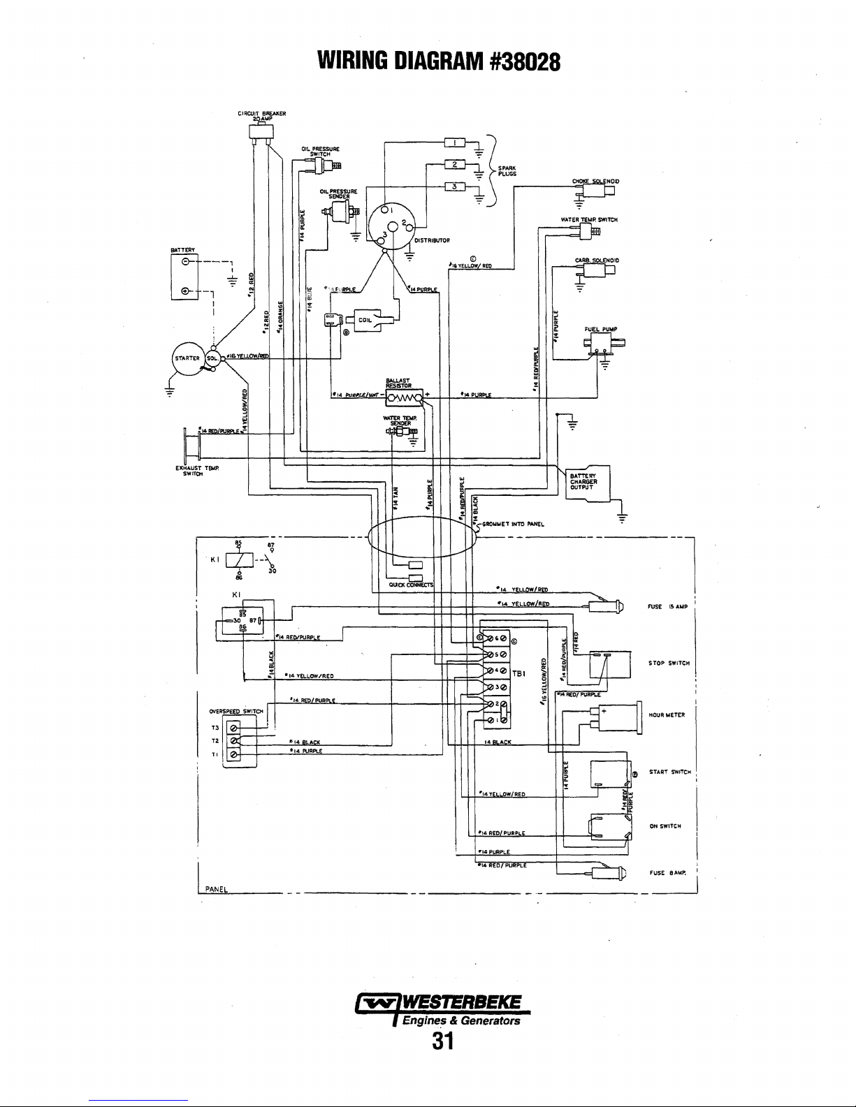
ElCHAUST
SW-
,.....
WIRING
DIAGRAM
#38028
~~-
1;
PAN
Eb
STOP
STA.AT
DN
rusE
SWITCH
SWIT(;tl
&.
SWITCH
1
'
Engine~
& Generators
31
Page 39

..------------------i+
r
-1
I I
CIRCUIT
: I
._
__
EIR£AKER
ao
AMP
J
WIRING
SCHEMATIC
I 2
voe
START
#38028
BATTERY
1111i.::-:__-------------,
SOL.ENOIO
FU
PUMP
1
TBH
1.....---
STOP
SWITCH
FUSE
8AMP
BALLAST
__
+_f'R""""""'-1--~~.-__:t..(
.-----..,.------
1 I
I I
'1"01L
PRESSURE
:
lSENDER
JtQPTJONALI
NOTE
3
OIL
PRESSURE
SWITCH
EXHAUST
SWITCll
TEMP.
FUSE
15AMP
.,_
._------1-------------+---t------r------jT3
ON
SWITCH
I
START
SWITCH
TBl·2
TBl-G
Cl
t ... -;
WATER
! :
SENDER
'
•!OPTIONAL.I
NOTE
TEMP.
3
OV£RSl'EEI)
DISTlllBUTOR
T!~----_..
$WITCH
3.
SENl1ER$
4.
MINIMUM
5.
REMOV£
SUPl'Ul!D
WITH
le:oMt.IENDED
JUMPER
BETWEEN
OPT!ONi\!.
WIRE
GAUIOE
TBl•I
INSTRUMENT
TO
.t.NO
REMOTE
TBl-2
l'A!!Eb.
WHEN
PANEL
USING
IS
Na.
REMOTE
14
AWC..
lw-,WEST'ERBEICE
.Engines
&
Generators
32
PANEi..
Page 40

REMOTE
f----
------
I I
I I
I I
:
I I
I I
' '
I I
I I
' '
I I
1 1
'
I I
1 I
I 1
:
I
:
: 0
: m
-----
STtP
INSTRUMENT
-ilziiEi>iru"R-s"TiiiPE
n.m
_____ ----
START
m1m
<REAR
rnm
VIEW!
PIN
---
33102
----------------:
12
R£0/PU
REMOTE
:
PANEL
i-------------~-------------------·----------,
CL
PRaUI! :
I m
TO
TDl•2
'tl4
RED/PUR
I I
:
TO
GUlCK
CONNECT
TERMINAL
m~
CONNECT
TERM I HAL
TO
TO
TO
I t
T8H
~
tl4
PUR
1
I
:
41
1114
LT.
BLUE
:
l
I I
•tl4
TAN
TB
H
..--!-i
;;.mmo;,;.;r...,..,,,.,-....,.---~
1
I
I
TBH
<ll-r:t~l4~RE=D~IP~UR~---~---------~
TB
41--.µlt""l
"-"Y
...
l.,.../R..,,E,_D
.
1
3
I I
·-~-~
r-------------------------~
-------------------'
.. ~ - - -
OPTl0"1AL
------
REMOTE ·START"PAIJEL.
I "lib
I I
I I
112
tu
116
ftelT.BlU[
il6
tl6
----
REDIPUR
PURPLE
PURPL[
TAN
BLACK
------·
(REAi(
- ---- - - - -
VIE\</)
P.IJ.
~3703
RED
r-------------------------------------------~
I
I
I
I
_J
. l
REMOTE
I I
I I
J I
I I
j
) START
I
J
I
I
I
J
j
l
I
~
~
~
~
~
(§
l:lt
~
t;z
RED/W/PU((
.-IZ.
Yl!.L/W/T2!D
STRIPE.
.STRJPI!
l
I
I·
~lb
PURPLE.
©
.ll'14
l<ED/PORPL.e
ON
~-
!'W/PUR
~STRIPE
. ~ J
~w
B~
°'
e:'.
~
V)
l'-?-t--"l-'-'..;...;:-.;..;::;.;:.,.
T4·~
I!'
'H---r~"-"'""-~.;;.:o..-+
I
I
I
I
I
I
,,,4
RED/kl/PUR
I
I
I
"'14
PURPLE:
I @
I
"'t'4
R@/Pl}RPLE
I
I
0 0
14·4
I
I
I
\o"1--t--
__
F_f4_...B_,L_AC:_..J(.""---
INSTRUMENT
{PN.
ti>
II 6 PURPLE
33702)
PURPlE
BLACK
ti&
BLACK
START
"'::'.:
~
"'
<>
..
V!ILTI
PANEL
{PN.33703)
TO
TBl-Z:·
__
l>
TO
Tel-4
TO
TB/
~G
...
TO
TBl-5
~
~
<>
; t
:
I
:
:
:
l
:
;
'
:
l
1
:
1
I
I
I
I
'
I
I
I
I
I
'
I
'
~-------------------"""'4'-Y_.E"'.L~/v.l~l~i<=E=·,D~.S=T_R~l-.P;.E
Engines &
33
"'14
REO/W/PUR
.Generators
STRIPe
____
,~
TO
TO
T61-'5
TBl-1
Page 41

GENERATOR
INFORMATION
USE
OF
ELECTRIC
The
power
required
than
is
required
require
(AC)
motors
circumstances,
easy-starting
applied
Because
run,
their
motor
is
repulsion-induction
current
varies
with
to
an
air
motor
to
In
general,
to
medium
MOTOR
(HI')
*NOTE:
more
for
this
is
that
larger
sizes.
Because
required
can
bring
experienced
and,
if
possible,
REQUIRED
Run
the
ator's
capacity,
on
the
generator's
checked
plant
and
meter
is
portable
NOTE:
tains
AC
generator:<!
volt
AC
good
motor
to
much
more
reqUire
than
loads,
after
the
motor
they
require 5 to 7 times
use
should
to
be
driven
to
start
as
to
the
load
compressor,
which
no
the
current
starting
SIZE
1/6
1/4
1/3
1/2
3/4
1
In
the
above
some
small
the
hardest
the
heavy
for
only
an
the
motor
in
starting
reduce
OPERATING
generator
and
data
periodically
the
appliances
not
installed
meter
and
When
the
vessel
equipment
AC
terminal
hot
leg
for
starting
MOTORS
to
start
an
keep
it
nmning
current
to
more
current
other
types.
such
as
washing
is
started,
be
avoided,
by
a
small
motors
require
run.
The
connected
for
example,
load
is
connected.
required
loads
will
AMPS
RUNNING
(AMPERES)
3.2
4.6
5.2
7.2
10.2
13
table
the
motors
starting
surge
of
current
instant,
up
to
speed
motors,
the
load
first
with
finally
loaded
plate.
to
ensure
it
supplies.
to
monitor
amprobe.
in
which
of
120
volts
block
the
vessel:<!
response
electric
after
startthem
to
They
machines,
such
as
much
whenever
generator.
from 2 to 4 times
current
to
it
An
will
to
start
be
approximately
FOR
maximum
than
for
types
(split-phase)
needed
the
generator
in a few
tum off
on
the
SPEED
no
load
applied,
to
its
The
output
proper
If
voltage
the
only,
be
configured
distribution
.from
the
motor
is
it
is
started.
than
start,
under
are
commonly
as
small
current
possible,
Capacitor
required
electric
require
115-Volt
Amps
larger
ones.
for
will
seconds.
all
other
electric
then
full
capacity
voltage
operation
an
AC
and
load,
generator
it
is
recommended
to
panel.
generator.
considerably
Some
others.
Split-phase
similar
used
or
where
power
tools.
to
start
if
the
and
as
much
to
start
any
motor
connected
more
current
motors
connected
as
follows:
AMPS
FOR
STARTING
(AMPERES)
6.4
to
22.4•
9.2
to
32.2*
10.4
to
72.8*
14.4
to
29.2*
20.4
to
40.8*
26to
52
for
Starting
The
reason
are
not
starting
motors
not
be
damaged
If
difficulty
electrical
motor.
at
half
as
indicated
should
of
the
generating
voltmeter
check
is
installed
provide
one
This
will
more
motors
on
loads
as
to
electric
motor
than
is
made
loads
the
gener-
be
or
amp--
it
with
con-
that
120
ensure
for
is
is
the
are
in
if
a
GENERATOR
Frequency
by
the
following:
•
When
output
•
When
output
Therefore,
drive
engine's
of
the
AC
GENERATOR
•
a
it
Maintaining
Connections
corroded,
salts,
up.
heating
•
For
petroleum
all
•
In
inspected
overheated
•
The
checked
for
not
cracking.
generator
identified
the
•
The
maintenance
noisy
•
Examine
of
motion
Repair
and
Carbon
WESTERBEKE
detector
even
The
from
exhaust
entering
If
carbon
air
FREQUENCY
is a direct
the
generator
frequency
the
generator
frequency
to
change
speed
output
connections
MAINTENANCE
and
dust,
engine
Clogged
and
reduce
unusually
based
surfaces
addition
the
to
to
for
terminals
drive
discs
periodically
any
evidence
be
allowed
The
shaft
by 6 radial
head.
rearw:mature
or
rough-sounding,
the
shaft
should
is
detectable,
must
cause
major
Monoxide
in
the
in
small
presence
the
engine
hose,
your
monoxide
and
correct
result,
.
is
is
60
is
is
50
the
generator's
must
be
reasonable
of
terminal
insulation
exhaust,
ventilation
life
severe
conditions,
coatings
reduce
rusting
periodic
tightness
and
on
single
if
of
incipient
to
become
bolts
which
must
be
marks,
bearing
is
required.
bearing
at
be
inspect
be
made
damage
Detector---------.
recommends
vessel's
living
amounts,
of
carbon
or
generator
or
that
fumes
boat.
is
present,
the
problem
ADJUSTMENT
of
engine/generator
run
at
1800
rpm,
Hertz.
run
at
1500
rpm,
Hertz.
frequency,
changed
cleanliness
of
cleaning,
of
possible
hardened
periodic
detected
quickly
is
monoxide
along
at
the
generator.
is
boards
and
rectifiers
surfaces
openings
may
carbon,
may
windings.
etc.
thin
should
be
sprayed
and
corrosion.
the
all
connections,
loose
or
damaged
bearing
generator's
for
tightness
cracking
rusty
because
fasten
the
steel
one
at
each
is
lubricated
However,
have
to
if
it replaced
inte'l:vals.
when
the
bearing
or
major
the
generator.
mounting a carbon
quarters.
deadly.
indicates
or
from
from a nearby
ventilate
immediately!
with a reconfiguring
important
start
are
cause
rust-inhibiting
generator
failure.
drive
SAE
the
force
components
Carbon
the
the
speed,
the
AC
the
AC
the
generator's
may
conducting
allowed
excessive
or
evidence
wires.
should
of
rust
may
disc
grade
of the 6
and
sealed;
bearing
No
is
applied.
and
shaft
an
exhaust
exhaust
vessel
area
as
illdicated
voltage
voltage
become
if
to
build
brushed
over
should
be
of
be
screws
and
Discs
should
accelerate
to
the
8,
comers
no
becomes
side
movement
If
for
wear.
will
monoxide
monoxide,
leak
elbow/
are
with
clean
of
side
rub
Engines & Generators
34
.
Page 42
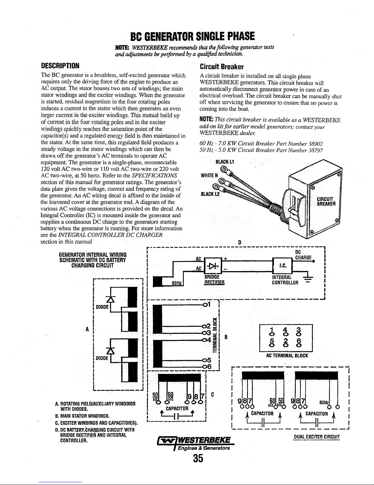
BC··
GENERATOR
NOTE:
WESTER/ltkE
and
ad,iuszment.r
rec()1M1e11(]s
be
performed
SINGl.E
that
~
lollowirig
by
a
quQJified
tecluikJan.
·PHASE
gen~r0ror
..
tests
DESCRIPTION
The
~C.generatoris·a·brushless,
requires
ACoutput.
stator
is
induces
Iru-g~
of
win~iD.g~
capapitot(s)
the
steady
drawn
equiPffient
120
AC
secti~n·oftbis
data
the
the
vatioos
Integi'al
supplies a
battery
see
section
only
the
driving
The
stator
windings
started, residual
~nt
etm:entinthe
a current
in
and
the
four
qu+cJdy
.a,nd
a
stator·
A.tthe
$~e
¥oltage
off
volt AC
f;\VIYwire,
plate
generator.
louver~
the!NTEGRALCONTROUER
in
the
generator's
The
two-wire
at
manual
~ves
An
cover
AC
voltage
Controller
contihuous
when
the generator is
in
this
manual
generator
50hert.z•
the
force
houses
the
exciter
magnetism
in
the
stator
exciter
rot~g
xeacheS
regulated
time.
th~
stator
or
for
voltage,
AC
wiring
at
the
generator
~ections
(IC)
is
DC
self--excite(l
of
th~
engine ~ produee
two
sets
ofwilldings;
windings.
in:
the
which
winding~.
po~es
the
~a®n
energy
this
regtl.l~.
wiridinss
AC
termina1.s
is
a
sjogle--phase,
110
volt
Refer
to
generator
current and
decal
is
moll~ted
charge
to
running.
V/hyn
four
rotating
then
generates
nus
mutual
and.
in
th~
pointof
.field
is
then
field
which
to
operate
AC
two-wire
the
SPECIFICATIONS
ratings.
frequency
is
affixed
end.
A
diagram
provided
inside
the
the
generators.
Fonnore
DCCHARG~
..
generatotwhich
the
the
gend'ator
poles
an
bpild
exciter
tJ1e
maintained
produces
can
then
be
AC
reconnectable
or.220volt
The generator's
rating
to
the
inside
of
the
on
the
decal.
generator
starting
infonnation
an
main
e~en
up
in
a
of
of
An
and
Circuit
A circuit breaker is installed
WFSTERBEK£ generators. This circuit
automatically disconnect generator
el:ectrical
off
coming
NDTE:
add-on1dtfor
WESTERBEKE
60
50
Breaker
overload:
when
s~rvicing
into theboat.
rhls
circuit
Hz -7.0
Hz
KW
-5.0 KW Circuit Breaker
The
the
breaker
earliet.
dealer.
Circuit
generator
model
on
all single
power
circuit breaker
to
ensure
is
available
generators;
Breaker
Pm1
Part
Number
Number 38797
phase
breaker
can
as
contact
will
in
case
of
be
manually
that
no
power
a
WESTERBEKE
your
38902
an
shut
is
GENERAT-OR.
SCHEMATIC
.
INTERNAL
WITH
CHARGING
CIRCUIT·
WIRING
DC
BATIERY
I
I
I
f u
! t
·-
~ii'""
- - - - - - - - - - ...............
f f
DUAL
ir·
EXCITER
&DHz
t !
---
CIRCUIT
I
-.I
Engines & 'Generators
35
Page 43

BCA
GENERATOR
(60
HERTZ
D
ONLY)
1
0
0
5
0
0
4
0
2
0
GENERATOR
WITH
INTERNAL
DC
BATTERY
WIRING
CHARGING
SCHEMATIC
CIRCUIT
ACTERMINAL
A.
ROTATING
WITH
B.
MAIN
C.
EXCITER
D.
DC
BRIDGE RECTIFIER
CONTROLLER.
FIELD/AUXILIARY
DIODES.
STATOR
WINDINGS.
WINDINGS
BATTERY
CHARGING
BLOCK
WINDINGS
AND
CAPACITOR(S).
CIRCUIT
AND
INTEGRAL
WITH
lwlWESTERBEKE
) Engines & Generators
36
Page 44

SINGLE
i.
i.
l.
EXCITER
Remove
generator,
the
capacitot(s).
Start
the
five.minutes
generatOr
current
from
appliances).
correct
obtain
the
Referring
check
the
voltage
meter.
Make
no-load
the
voltage
proceed.
~e
louvered
covering
generator
so
is
operating
the
Make
Adjtist
correct
to
the
geiietator's
across
the
sure
voltage
output
NO·LOAD
metal
the
AC
and
allow
the
engine
canwarnt
without
generator
sitte
the
fuel
engine
AC
neutral
you
is
115 -124
is
(that
the
throttle/speed
speed
load
connections
no--load
lead
record
higher
.ac
GENERATOR
NotE:
WisiEi@EKE
and
Odfustments
be
:econtmends
performed
SINGLE
by
a
VOLTAGE.ADJUSTMEIT
plate,
at
the
baclc
of the
tetminat
engine's
or
connections.and
iHo
run
any
equipment
is,
shut
8peed
before
voltage
and
the
this
readitig.
volts
at
lower
· ·
for
apprpxhnateJ.y
up.
:Make
drawing
off
all
(HertZ)
linkage
as
proceeding.
diagram
by
:measuring
hot
lead
The
60.5
- 6L5
than
specified,
sure
the
~C
electrical
is
needed
below,
the
with
a volt
generator's
Hertz.
If
@
@·
to
·
PHASE
~
thi!follt>wing
qualified
technici<in.
----------------.
A
.WARNING:
age
11tt/:ustmsnt
aapaottoraan.
any
wiring
addition,
·
nilnt
whils
fingers
to
5.
There
are
minal,
tow,
then
nect
the
tor's
no-load
numbered
number.
tenninat
6.
· Jf the
generator's
because
numbered
or
the
vpltage.needs
bered
plug
Oenetator
generator
Do.not
While
produce
tan
JlrodutJB
attempting
t1J'ege11111'8tor
be
caught
three
plugs
#7,
#8,
and
disconnect
plug
with
voltage
plug
and
Note
that the
may
be
any
the
voltage
plug
is
is
Ct>nnected,
Troubleshot)~
attlJmpt
the
a
4lltJ.50D
11
to
make
In
the
grouped
#9.
If
the
the
next
is
high,
connect
plug
one
no-load
needs
already
to
be
tests
to.make a no-load
generator
severs
Is
operating
generator's
the
lower
higher
presently
of'the
voltage
to
connected
lowered
refer
Is
volt
e/IJCtrlcal
a
no-load
for
the
generator's
numbered
number.
then
disconnect
the
plug
three
cannot
be
increased
and
to
the
Gui~e).
volt·
operating.
charge.
voltage
could
rotor.
right
no-load
with
connected
plugs
be
to
the
the
WESTERBEKE
Touching
shock.
ad/ast·
cause
capacitor
plug
and
If
the
the
the
next
to
available.
adjusted
and
the
right
lowest
The
In
your
voltage
congenerahigher
lower
this
highest
terminal,
num-
ter-
is
BC
115VJ50Hz
.
<.i:lUilC3)
@
23DV/50Hz
4.
Shut
off
the
generator.
(60
Hertz
#6,
or
·
capacitor(s).
AWAR~INfl;
hailtlllllg
t/ally /stbal
power
NOTE:
insulated
any·excess
as
they
aharge
source~
Simply
cross
(plastic
handle)
electricity.
Make
50
Hertz
#S) is
Capacitors
store
eleatrlaltj
even
when
the
capacitor's
screwdriver.
sure
pltlgged
11111Stlls
and
dlsaonneotet/
two
II
GROUNDED
INSIDE
GENERATOR
the
correct
into
111$/:hlJffled
can
paoka
from
terminals
This
will
discharge
Or
Hertz
the
before
poten-
their
with
TO
THE
lead
an
THE
CASE
A
WARNING:
tlie
unused
With
11aah
other
housing.
5
BCD
See
the
ENGINE
ADJUSTING
Make
leads
atB
In
or
Jn
contact
GENERA.
ron
.120V/60Hz
ADJUSTMENT
THE
ENGINE
certain
place
BACK
SPEED.
the
Insulating
and
atB
NOT
with
the
gensrator's
NOTE:
THE
SHOWN
CONNECTED
DEMONSTRATION
THESE
CONNECTIONS
BE
MADE.
END
SHOWN
sectlon
in
covers
In
contact
ll
WIRE
this
JS
AS
OF
HOW
CAN
manual
on
A
for
Engines & Generators
37
Page 45
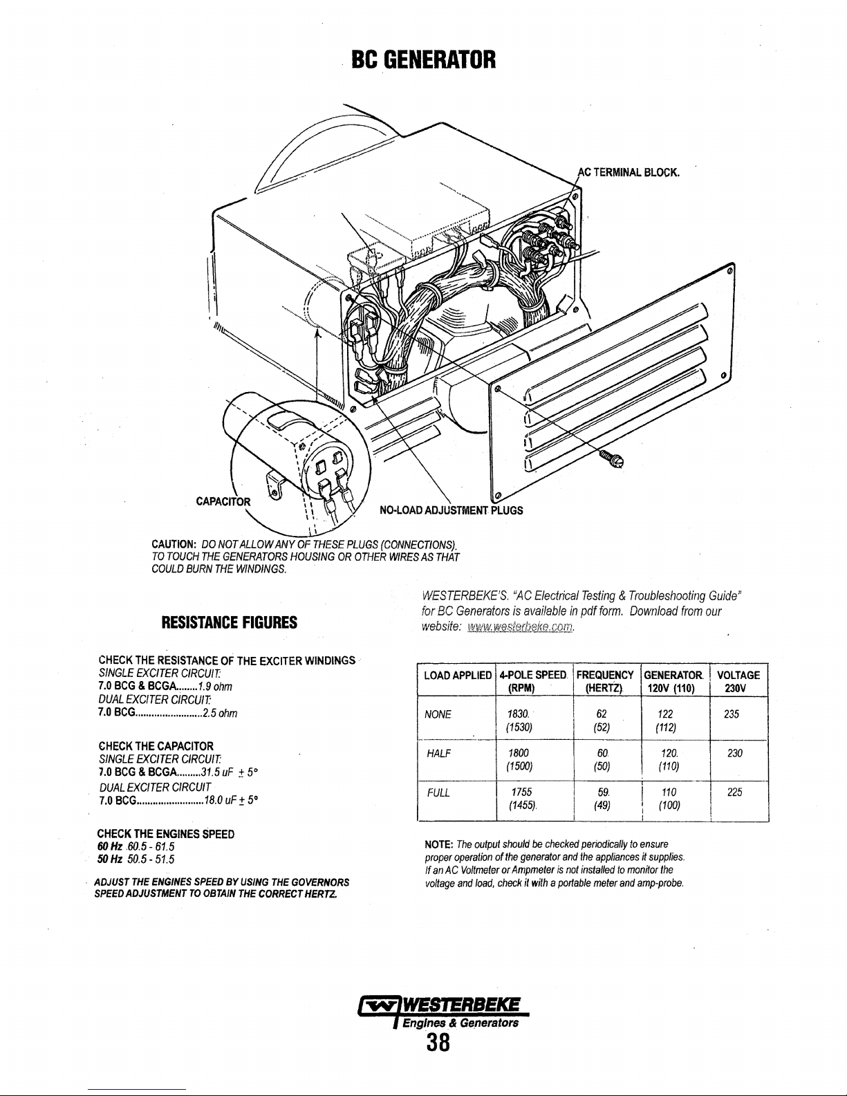
BC
GENERATOR
CHECK
SINGLE
7.0
DUAL
7.0
CHECK
SINGLE
7.0
DUAL
7.0
CHECK
60
50
·
ADJUST
SPEED
THE
RESISTANCE
EXCITER
BCG
&
BCGA.
EXCITER
BCG
.........................
THE
CAPACITOR
EXCITER
BCG
&
BCGA.
EXCITER
BCG
.........................
THE
Hz
Hz
ENGINES
.60.5 -61.5
50.5
-
51.5
THE
ENGINES
ADJUSTMENT
RESISTANCE
CIRCUIT:
.......
1.9
CIRCUIT:
CIRCUIT:
........
31.5
CIRCUIT
SPEED
TO
OF
ohm
2.5
ohm
uF ± 5°
18.0
uF
SPEED
BY
OBTAIN
FIGURES
THE
EXCITER
±
5°
USING
THE
CORRECT
WINDINGS··
THE
GOVERNORS
HERT2.
WESTERBEKE'S.
for
BC
Generators
website:
LOAD
NONE
NOTE:
proper
If
voltage
¥J!MtJf!!..~eke,com..
APPLIED
HALF
FULL
The
operation
an
AC
Voltmeter
and
output
load,
"AC
is
4-POLE
(RPM)
1830
(1530)
1800
(1500)
1755
(1455).
should
of
the
or
Ampmeter
check
Electrical
availabfe
SPEED.
..
be
checked
generator
and
is
it
with a portable
Testing & Troubleshooting
in
pdf
form.
FREQUENCY
(HERTZ)
62
(52)
60
(50)
59.
(49}
I
periodically
the
appliances
not
installed
meter
Download
to
ensure
to
monitor
and
amp-probe.
from
GENERATOR
120V
(110)
122
(112)
120.
(110)
110
I
(100)
l
it
supplies.
the
Guide"
our
VOLTAGE
230V
235
230
225
Bf.5!J.WEB'l!IUIEICE
Engines & Ge!lerstors
38
Page 46
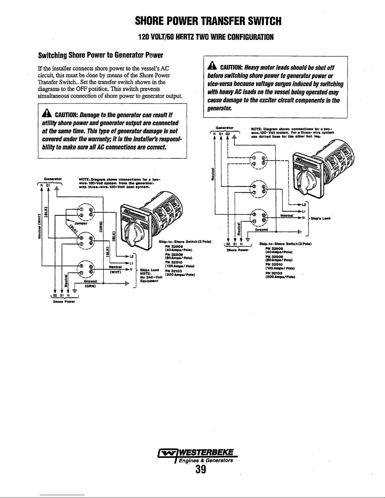
SHORE
120
POWER
VOLT/60
HER'll
TRANSFER
TWO
WIRE
CONFIGURATION
SWITCH
Switching
If
the
installer
circuit,
this
must
'Il.'ansfer
diagrams.
simultaneous
Switch
to
A
CAUTION:
utility
shore
at
the
same
coVBl'fJd
bllity
ta
under
make
Shore
Power
connects
be
done
..
Set
the
the
OFF
position.
connection·
Damage
power
and
time.
This
the
warranty;
sure
all
.
NOTE:
Wire,
12Q•Volt
-
...
to
shore
by
means
transfer
of
shore
ta
generator
type
AC
connections
Diafll'UI -
.,..
,..-1
...
Generator
power to
of the
switch
This
switch
power
the
ge11Brator
output
of
generator
It
Is
the
-ctl-
... ffOm -
120-VOlt
-t
Power
the
vessel's
Shore
Power
shown
in
prevents
to
generator
can
resun
are
connected
damage
Installer's
are
col'TBl:t.
fer
a
two-
..,._,
.,...
....
AC
the
output.
ff
Is
not
rssponsl·
. A
CAUTION:
before
switching
rlt:B-versa
with
hBaVy
caUStJ
damage
gllllflrator.
"6-nltor
•
1 N
13
G2
1
t
I
I
I
:
Heavy
motor
shore
because
AC
.=.
I
L---~
r--:---\<a> /
I ,
I
I
I
I
voltage
loads
an
to
the
exciter
NOTE:
1 wire.120-Volt
-
dotted
.....
-,
ft
__
.,.
leads.should
power
to
surges
the
vessel
cltcull
Dialdlll
llllowll
uatem.
11-
for
bs
generator
Induced
being
operated
compollflnts
con•ct-
Far
•
three•
the
-·
bot
shut
power
by
switching
In
for a
--
wire
syatern
199·
og
or
may
the
Eng~ne_s
&_Generators
-
39
Page 47
LAY-UP & RECOMMISSIONING
General
Many
owners
rely
on
their boatyards
including
season
accomplish
The
own
if
These
engine/generator during a lay-up and
you
If
your
provide assistance.
Propeller
The
be opened
out of the
storage in the cradle.
· severe
the boat is
shaft
apply to
not
period
Fresh
A
mended
This
depending on
make
Should
from
Operate
ture of the antifreeze concentration throughout the
system.
Lubrication
With the engine
sump.
new
LUBRICATING
change".
Run
sure
engines
or
for
procedures
lay-up
others
do
procedures
with
its
you
have
local
transmission
strain
has
actually
small
in
use,
of
time.
Water
SO~SO
solution
for
solution
sure
more
the engine block and add a more concentrated mixture.
the engine
Then
and generators,
long
periods
of
inactivity.
lay-up preparation themselves.
which
follow
and recommissioning, or will seive
the procedures.
should provide protection
maintenance
any
qu~stions
servicing
Shaft
up
and
water
or
on
the propeller shaft or coupling or both,
taken
out
boats that
unless
Cooling
use in the fresh water cooling system at
may
the
the.
antifreeze
antifreeze
recheck the antifreeze solution's strength.
needs.
regarding
dealer.
He
Coupling
and propeller half
the bolts removed when
moved
from land to
The
flexibility
or
put
in
been bent
they have been
by
are
hauled out of the water
Circuit
of
antifreeze and distilled
require
a higher
area's winter climate. Check the solution to
protection
be
needed,
to
ensure
System
warm,
drain
Remove
oil.
the
there
and replace the oil filter
Use
the
correct
grade
OIL
pages
in
engine and check for proper oil
are
no
leaks.
to
prepare their
for
lay-up
during
Others
prefer to
will
allow
you
to
for
also
help
lay-up
procedures, call
will be more
(Propulsion
couplings
of
the
water.
these strains. This
dry
concentration
is
drain
a complete circulation
all
the
of
oil.
this
manual
than
Engine]
should
the
water,
and
the boat
In
some
for
a considerable
water
adequate.
an
appropriate
engine.oil from
,and
fill the sump
Refer
to
for
pressure
craft,
the
off-
perform your
as
a checklist
your
familiarize
willing
to
always
boat is hauled
during
oftens
puts a
while
cases, the
does
not
when
is
recom-
all
times.
of
antifreeze,
amount
and
mix-
cooling
the
oil
with
the
ENGINE
"engine
and
oil
make
Fuel
System
Top
off
or
higher. A fuel
stabilizer
gasoline/water
Re-install
up
any
Fuel
System
Top off
such
as
control
that.the
filter/water seperator
in
ypur
bas
one,
Change the
fuel
system,
for
5 -
system.
the
fuel
needed.
allow
movement
equipment
Raw
Water
Close the
hose from
gallon
check
the engine
any
zinc
anode
Start
the
fresh
water
stop
the
solution
protection in
Start
the
through
the
engine.
water
as
providing corrosion
Remove
antifreeze
Examine
cover gasket
until
recommissioning,
your
fuel
should
separator and
and
make
spilled
fuel.
your
fuel
BIOBOR
algae
and
additives
primary
and
clean
fuel
as
10
minutes
Check
system
Operating
on
the
Cooling
through-hull
the
fitting.
bucket
of clean
the
zinc
and
debis
is
located.
engine
through the
engine
slightly
your
engine
the
raw
This
circuit
from
the
impeller
mixture
the
impeller.
[Gasoline]
tanks
conditioner such
be
(Dleselj
tanks
and
condition the
used
fuel
filter elements
needed.
for
during
of
engine.
anode
clean or replace it
from
Clean
and
and refill
stronger
and
water
antifreeze
Do
with
unleaded
added.
Change
clean
certain
there
with
No.2
STABIL
are
compatible with
used
in
the
filter/water
the seperator sediment
Start
the
to
make sure
any
leaks
that
this
servicing,
the engine
the treated
&asoline
as
MARINE:STABIL
the element in your
the
metal
are
no
diesel
should
be
fuel.
Care
system.
seperator,
on
the engine
engine
no
air
is
may
have
correcting
for
5 -
10
fuel
through
Circuit
fitting.
Remove
Place
the
end of
this
fresh
water.
Before starting
found
in
the
primary
as
required
inside
the heat exchanger
the
raw
water
strainer.
allow
the
raw
water
system.
area.
allow
system.
freezing
protection.
from
will
accompany
Get a replacement,
not
replace the impeller
the
than
all of this
mixture
during
your
but
replace
When the
bucket with
needed
for
mixture
Once
the
should protect the
the winter
raw
water
it, so
the cover
~f ~9
~ctane
bowl.
leaks.
Clean
fuel.
Fuel additives
added
at
this
time
should be taken
the
primary
Change the element
if
the
bowl.
and
and
allow it to
left
in
the
been created
minutes
the
the
raw
hose
heat exchanger
and
where
pump
bucket
an
antifreeze
winter
to
bucket
lay-up,
pump
cat.ch
if
needed,
(into
and
fuel
fuel
system
bleed
the
run
fuel
them
as
will
help
injection
water
intake
into a five
the
engine,
also
clean
the
to draw the
is
empty,
freeze
be
drawn
is
empty,
raw
as
well
(some
it
in a bucket).
and a
the
pump)
gasket
to
in
on
zinc
stop
A
CAUTION:
oil
in
the
combustion
t:h11111it:als
Internal
parts.
sump
deposits
wlllch
Do
owr
t:a11
not
leave
the
lay-up
combine
redut:e
the
psriod.
to
the
engine's
Engine
prodace
l«e
al
your
aid
BllfllllB
oil
harmful
engine's
and
Intake
Place a
opening of
shove the
recommissioning,
you
note
exhaust port
lwlWESIEHBSKE
.
..
l
···.
Engines
···········;41r···········
~
.Ge11erators
Manifold
clean
the
cloth
may
need
to
remove
and
Thru·Hull
cloth, lightly
intake manifold
out of sight.
and
assistance
the cloth prior to start-up.
can
be
an
attempt is
of
blocked
soaked
to
(If
it
the
seivicing
in
the same
block
is
Exhaust
in
lubricating
the
not
visable
made
manner.
oil,
opening.
at
to
start
dealer).
The
thru-hull
(CONTINUED)
in the
Do
the
engine,
Make
not
a
Page 48

Starter
Lubrication
if access
battery connections
the
connections removed
Cylinder
If
WESTERBEKE
access
cylinders
cylinder
Make
line sealing washers.
starter.
you
anticipate a
to
sure
Motor
and
cleaning
to
the starter pennits
Take
care
Lubrication
long
recommends
the
cylinders. Squirt light lubricating oil into
to
prevent
walls.
you have replacements
LAY·UP & RECOMMISSIONING
of
the
starter
drive
pinion
its
removal.
are
shut off before attempting
in
properly replacing any electrical
from
the
starter.
(Diese4
lay-up
period (12 months or
removing
the
piston
rings
from
for
Make sure
the
sticking
the
injector
fuel
is
advisable,
the
to
remove
more)
injectors
the
to
the
and
return
for
Spare
Parts
Lay-up
time provides a
WESIBRBEKE engine
belts
or
coolant
hoses
spares
kit
and
order items
used
during the lay-up,
to
SPARE
PARTS
good
to
need
not
such
section of
opportunity
see
replacement Check your basic
on
as
this
flecommissioning
The
reco~ssioning
seasonal
those
section regarding preparation for
However,
counteracted before starting the
lay-up
presented
some of
of
your
generally
in
the
PREPARATIONS
the
lay-up
WESIBRBEKE engine after a
follows
procedures
if
external
hand,
filters
manual.
the
starting
engine.
to
inspect
items
or
replace those
and
zinc
same
procedures
FOR
STARTING
and
normal starts.
will
your
such
as
drive
items
anodes. Refer
as
need
to
be
Intake
Clean
cloth lightly soaked in lube oil around
block
through-hull
start-up!
Cylinder
Spray fogging
arrestor removed,
eil
spark
NOTE:
and
Manifold I Gasoline]
the
filter
screen
in
any
opening,
exhaust
Also
port.
Lubrication
oil
into
the
while
will
stall out
plugs
The
regapping
the
engine
for
winter protection.
spark
plugs
at
spring
will need
the
flame
arrester,
place an oil-soaked cloth
Make a note
[Gasoline]
open
air intake, with the
the
generator is running. The fogging
and
coat
to
be
commissioning.
Batteries
If
batteries are
make sure that
way,
to
the
batteries will not remain fully
be
subjected
batteries
environment
A
WARNING:
highly-explosive
arcing
smoke
serviced.
vicinity
Transmission
Check
Wipe
off grime
Protect
corrosion
to
be
they
prevent
them
to
severe environmental conditions, remove
and store
them
or a lighted
or
allow
an
Shut
off
to
prevent
(Propulsion
or
change the fluid
and
the coupling
coating. Check
left on board
are
fully
from
in a wanner, more compatible
Lead
acid
gas,
which
cigarette,
open
all
electrical
electrical
charged,
freezing.
batteries
can
cigar,
flame
near
arcing
during
charged,
be
equipment
Engine]
in
the transmission
grease and
and
touch
the output flange with
that
the transmission vent is
and
place a
the
flame arrester
to
remove
cloths
the
valves, cylinders
removed
and
If
there
ignited
or
the
for
the lay-up period,
will remain
is
any
or that they will
emit
hydrogen,
by
pipe.
battery
in
during
servicing.
as
up
any unpainted
clean
in
the
prior
flame
cleaning
that
doubt that
electrical
Do
not
being
the
required.
an
anti-
open.
to
to
and
the
a
areas.
1.
Remove the oil-soaked cloths
2.
Remove
the old gasket Install the raw
removed during
Install the
3.
Reinstall the batteries that
up,
terminals
Check
A
and
batteries
can
cigarette,
open
electrical
electrical
4.
Remove
proper
5.
· it
· solution from the
6.
the
raw
raw
and
reconnect
are
clean
to
make
CAUTION:
eye
protection
emit
be
ignited
cigar,
flame.near
equipment
arcing
the spark
tightness
Check
the
condition
circuit and
is
engine
short period of
advisable,
service,
heat
area.
Start
in
the
this
clean
not necessary
is
put
as
to
inspect
exchanger
the
engine
PREPARATIONS
manual.
water pump cover
lay-up
water
pump
the
battery
and
sure
that the batteries
Wear
rubber
when
hydrogen, a highly
by
electrical
or
pipe.
the
battery
In
during
plugs,
[gasoline].
of
or
replace
to
flush the antifreeze/fresh
raw
water coolant
into
operation,
time
with
either
an
the
and
clear
in
accordance
from
the
intake manifold
and
gasket.
water
pump
(or a replacement,
cover
with a new
were
removed
cables,
making
that the
connections
are
gloves, a rubber
servicing
batteries.
explosive
arcing
or a lighted
Do
not
smoke
being
serviced.
the
vicinity
ta
prevent
servicing.
wipe
clean,
re-gap,
the
zinc
anode
in
the
anode
as
system.
the
system
no
end of
area
where
any and
FOR
adverse
affects.
season
or recommissioning
the
zinc
811
zinc
with
procedures
INITIAL
START-UP
and
impeller
if required).
cover
during
the
sure
are
tight.
fully
charged.
apron,
LBSd
gas,
or
allow
Shat
and
the
raw
needed.
water
When
will
self-flush in a
It
is
is
located
debris
described
discard
gasket.
lay-
the
acid
which
an
off
install
water
Note
the
in
from
section
all
to
that
the
that
of
Engines & Generators
41
Page 49
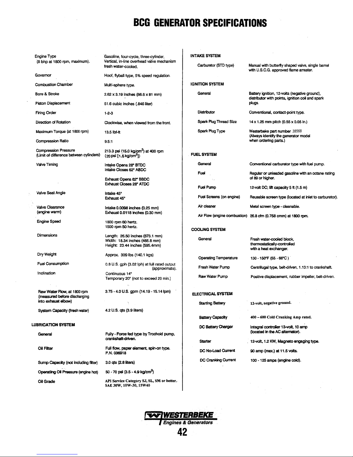
Engine Type
(8 bhpat1SOO
Governor
Combustion
Bore & Stroke
Piston Displacement
Firing
Direclion of
Maximum Torque
Compression
Compression Pressure 213.3 psi {15.0
(Limit
Valve
Valve
Valve
(engine
Engine
Dimensions
OryWejght
Fuel
Inclination
rpm.
Chamber
Order
Rotation
Ratio
ofclillerence
liming
Seat
Angle
Clearance
wann)
Speed
Consumption
maximum}.
(at
1800
between
rpm)
cylinders)
'Gasoline,
tour-cycle, three-cylinder,
Vertical,
In-line
fresh
water-cooled.
Hoof,
flyball
Multi-ephere type.
2.62 x
3.19
51.6
cubic
inches
1·2-3
Clockwise,
13.S lbf.ft
9.5:1
(20psl
[1,5kg/cm
lntipal
Opens
Intake Closes 62"
Exhaust
Opens
Exhaust
Qoses
lntake4S•
Exhaust45°
Intake 0.0098
Exhaust
0.0118
1
BOO
tpm
60
1500
tpm
50
Length: 26.50 Inches
Width: 18.34 Inches (465.8 mm)
Height: 23.44
Approx. 309 lbs (140.1 kgs)
0.8
U.S.
gph
Continuous 14°
Temporary
BCG:
overhead
type,
S'lb
speed
Inches
(66.6 x
(.846
when viewed
kg/~
2
))
ZS'
BTOC
A80C
62"
BBDC
ZS'
ATDC
inches
(Q.25
inches
hertz..
hertz.
inches
(59S.4mm)
(3.02 lph)
2r1'
(not
to
GENERATOR
v81Ve
reg\dation.
81
mm)
lirer)
from
at
400
mm)
(o.30
(673.1
at
full rated
(approximate).
exceed
mechani$m
the front
rpm
mm)
mm)
Q!.ltput
20
min.)
INTAKE
IGNmON
FUEL
COOLING
SPECIFICATIONS
SYSTEM
Carburetor
General
Dislrlbulor
Spartc
Spark
General
FUii
FUii
Fuel Screens (on engine)
Alrcleaner
Alr
General
Operating
Fresh
Raw
(STD
type)
$YSTEM
Plug
Thread
Size
Plug
Type
SYSTEM
Plll'lp
Flow
(engine combustion) 26.8 elm
SYSTEM
Temperarure
Water
Pump
Was.er
Pump
Manual
with butterfly shaped
with
U.S.C.G.
approved
Baltery
ignition. 12-volts (negative ground),
distributor with points, ignilion
plugs.
Conventional,
14 x
Weslerbeke
(!Jways Identify lhe generator model
when
Conllentional carburetor
Regular
89
of
12-volt
Reusable
Metal
Fresh
thannoslalically-controlled
with a
130 • 150"F (SS - 66°C)
centrifugal type,
Positive
contact.point typ$:
1.25
mm
pitch
part
ordering pans.)
or
unleaded
or higher.
DC;
Ill capacity 5
screen type (localed at
screen
type • cleanable.
(O.
758
water-cooled
heat
exchanger.
displacement, rubber
ftame
(O.SS
number
gasoline
cmm)
at
block,
belt-<iriven,
valve,
arrester.
coil
x 0.05 in.)
38568.
type
with
with
ft
(1.5
m)
1800 rpni
1.13:1 to
Impeller,
~ngle
and
spark
fuel
pump.
an
octane rating
inlet
to carburetor).
crankshaft.
bell-driven
barrel
3.75
4.2
Fully-
·4.0
U.S.
FoRle
Raw
Walll!I
(~before
into exhaust
LUBRICATION
General
Flow,
at
discharging
elbow)
SYSTEM
1800
rpm
crankshaft-driven.
01 Flter
Sump Capacity (not
Opendlng
01
Grade
01
Pressure
lncllXling
(engine
FWI
ftoN,
P.N.036918
titer) 3.0 qts (2.8 liteia)
hot)
50
• 70 psi (3.5 •
API
Servke
SAE
JOW,
U.S.
gpm
(14.19·1S.14lpm)
qts (3.9 liters)
fed
type byTrochoid
paper
element, spin-on type.
4.9
k9'cm2>
Category
lOW-30, 15W40
ELECTRICAL
pump,
Starter
DC
SJ,
SL,
SM
or
better
..
,...,,.,-
· ·
;Engi~
•.
&:Generators
DC
SYSTEM
No-Load
Cranking
42
C\J'rent
Current
12-volt, negative ground.
400
-600
Cold
Cranking
Integral
COlllroller
in
the
KW,
(rrax.)
13-volt,
AC
alternator).
MagnalX>
al
11.5
volts.
(located
. 12·volt, 1.2
90
amp
100 • 125 amps (engine cold).
Amp rated.
10
amp
engaging type.
Page 50

AC
GENERATOR
General
Voltage
NOTE:
Rallng
ED
Hertz
·
BCG
BCGA
models
(Vdts
!>CJ
(1800 ipm)
GENERATOR
SPECIFICATIONS
BrusNesa.
Self
8lCCiting.
Pfe.lubricaled.
Reca•ledable 120 volts
~
120
vdls -
220
valls -50 hertz.
Vollage regulation: :!:5%
f!M-load.
Frequency
no-load
are
60
herlZ
Oliy.
This
model cannot be converted
120vclls
four-pole,
to fdMoad.
l'IMJMng
Capacitor
single-beamgdeslgn.
60
hartz
regUallon: :!: 3 hartz
58amps
fielcl.
salUlaled
no-load
to
50
field excitation.
to
(5%)
hertz.
50
Hertz (1500 ipm)
/IC
Circuit
G9lerala'
NI
AecPrernerD.
at1800rpm
NOY£:
Engkie
Reqtftnenls,
at1800ipm
TUNE-UP
Spark Plug
Contact Point
I ming
Dwell
Braker
Cocling
(60 hertz).
lncraase
air supply 15% fer
Combuslion
SPECIFICATIONS
Angle
(60
Gap
Clemance
"6
harlZ),
so
her1Z
220valls
To be rared
amperage and
2.50
efm
opera11on
26.8
efm
0.028-
0.011
1
O"
:t
58-66"
at
1~
wllage
(7.0
cmn)
(1500 rpm).
(0.758 cmm)
0.031 inches
-o.01s
inches {0.4
.s'
BTDC
at
23amps
of
the
CUput
(0.70-
1800
ganer;ttOr's
0.80
-o.s
mm)
rpm
rated
mm)
w
WESTERBEKE
Engines & Generators
43
Page 51
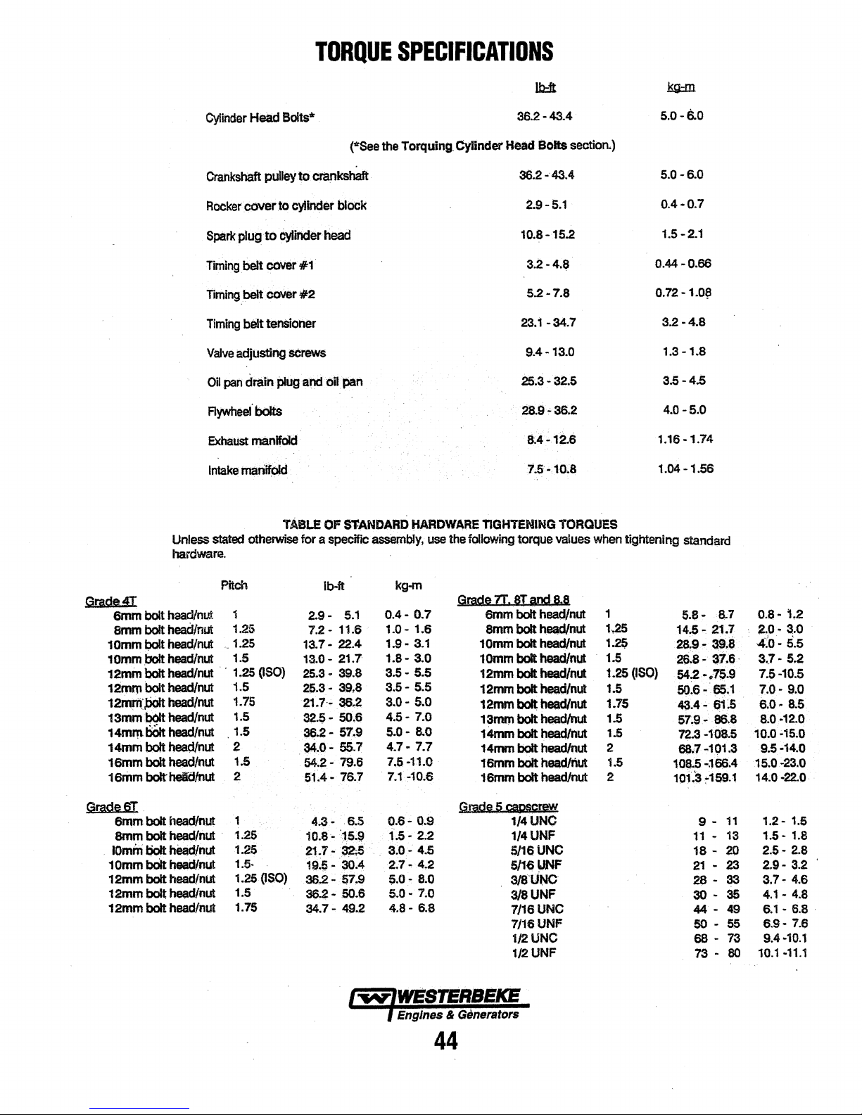
TORQUE
SPECIFICATIONS
Cylinder
Crankshaft
Rocker
Spark
Tuning
Head
puUeyto
cc>ver.to
plug
to
belt
CCM!ir
Bolts*
Cytlfider
iming belt cover
Timing
belt tensioner
Valve
adjusting
OU
pan
drain
plug
Aywheel
Exhaust
Intake
boltS
manlold
rnatiifplcl
crankshaft.
cylinder
head
#1
*2
screws
and
(*See the Torquing. Cylinder
bloek
oil
pan
36.2·43.4
Head
BOits
section.)
36.2-43.4
2.9-5.1
10.8-15..2
3.2-4.8
5.2-7.8
23.1-34.7
9.4-13.0
25,3.32.s
28.9~36.2
8.4-12.6
7.S'· 10.8
s.o-6..o
5.0-6.0
0.4-0.7
1.5-2.1
0.44-0.66
0.72·1.0{!
3.2
-4.8
1.3
-1.8
3.5-4.5
4.0-5.0
1.16-1.74
1.04-1.56
Unless
hardware.
Grade4T
6mm
bolt head/nut
armn
bolt
head/nut
bait
1omm
1 omm
12mm
12mm
1amm:PcJ1t
13mm
1~
14mm
16rnm
16Jrim
Grad96T.
6rnm
emm
1omm
10mm
12mm bolt head/nut
12mmbolt~nut
12mm
head/nut
.bolt
h.Unut
bolt
head/nut
bolt
head/nut
m.itnut
bolt
head/nut
bOlt
headfl1Ut
bolt
head/nut
bolt
head/nut
bolt
helCl/nut
bolt
head/nut
bolthead/nut
t;o1t
h8ad/nut
bOlt
head/nut
bolt head/nut
stated
otherwise for a
Pitch
1
125
'•
1.25
1.5
..
1,25
1.5
1.75
1.5
1.5
2
1.5
2
1
1.25
·
1-25
1.5·
1.25(1$0)
1.5
1.75
(ISO}
TABLE
2.9-
7.2-
13.7·
13.0- 21.7
25.3
25.3-
21.7·~
32.$- 50,6
36.2-
34.0- 55.7
54.2-
51.4-
4.3-
10.8 -
21.7.
19~-
36,2-
~-
34.7-
OF
S'f.ANDAAD
specific
lb-ft
assembJy,
5.1
11.6
22.4
• 39.8
39,8
36.2
57.9
79.6
76;7
6.5
:,.S.9
32-.S
.
~:4
57.9
50.6
49.2
HARDWARE
use
the
following
kg-m
Gm.di
0.4-
0.7
1.0-
1.6
1.9.
3.1
1.8-
3.0
3.5.
5.5
3.6-
5.5
3.0-
5.0
4.6-
7.0
5.0-
8.0
4.7-
7.7
7.5-11.0
.
7.1
~10.6
Gmdg
0.6-
0.9 1/4UNO
f.5-
2;2
a:o-
4.5
2.7-
4,2
s.o-
8.0
5.0-
7.0
4.8-
6.8
TIGHTENING
torque
ZI.
8I
arnm
amm
10mm bolt
1omm
12nvn
12mm
12mm
13mn.l
14mm
14mrn bolt
16mm
16mm
imd
bolt head/nut
bolt
head/nut
head/nut
bolt
head/nllt
bolt
head/nut
bolt
head/nut
bolt
head/nut
bolt
head/nul
bolt
i.adlnut
head/nut
bolt head/nut
bolt
head/nut
5
~ggrew
1/4UNF
5/16UNC
5/161JNF
3/8liNO
3/8UNF
7/16UNC
7/16UNF
1/2UNO
1/2UNF
TORQUES
values
When
a.a
tightening
1
1,25
1.2$
1..5
1.25(1$0)
1.5
1.75
1.5
1.5
2
1.6
2
standard
8.7
11
13
20
23
33
35
49
55
73
80
0.8·
2.0·
·
4:o-
3
7.5-10.5
7.0·
6.08;0-12.0
10.0•15;0
9.5·14.0
15.0-23.0
14;0 ·22.0
10.1
s.e
·
14.5.
21.7
28,9·
a..e
26.8-
3:7.6·
542-~7?~9
50.6. 65;1
43.4.
61~
86.8
67.9-
72.3-108.5
68.1-101.3
10$.5
-~66;4
101.3
:-1$9.1
9 •
11
-
18
-
.
21
28
-
30
-
44.
50 -
68
-
73
-
1.2
3.0
5~5
..
7·
5.2
9.0
8.5
1.2-
1.5
1.5·
1.8
2.5-
2.8
2.9·
3.2
3.7-
4.6
4.1-
4.8
6.1-6.8·
6.9-
7.6
9.4-10.1
•11.1
44
Page 52

CONTACT
YOUR
SUGGESTED
WESTERBEKE
WESTERBEKE
DEALER
SPARE
MARINE
FOR
GASOLINE
SUGGEST{ONS
PARTS
GENERATORS
AND
ADDITIONAL
,
INFORMATI9N
MANIFOLD
I
THERMOSTAT
GASKET
SPARK
AND
PLUGS
CAP
8~
&
15AFUSES
l_
, . ·
. I
~~;
FILTER
SCREEN
.
1
1111\111
HARDWARE
MOLDm
HOSE
KIT
KIT
DISTRIBUTER
ANDW1RES
CAP
HEAT
EXCHANGER
GASKET
AND
Vo.
BSTERBEKE also offers two Spare Parts Kits,
each packaged in a rugged, rust free toolbox.
KIT
A includes the basic spares.
KIT
B is for more extensive off-shore cruising.
END.·;,;
O·RING . ..
KIT
A
Impeller Kit
Heat Exchanger Gasket
Oil Filter
Drive Belt
Zinc Anodes
Spark Plugs
WESTERBEKE
ENGINE
AND A GALLON
SPARE
PARTS
RAW
GASKET
RECOMMENDS
OIL
(YOUR
BRAND)
OF
PREMIXED
KITS
~;!,..
WATER
PUMP
AND
IMPELLERS
FOR
CARRY/NG
COOLANT.
AN
OIL
ENOUGH
CHANGE(5
SPARE
QTS.)
KITB
Impeller Kit
Water Pump Repair Kit
Thermostat Kit
Zinc Anodes
Complete Gasket
Heat Exchanger Gasket
Oil Filter
Drive Belt
Spark Plugs
Kit
l'W"lWESTERBEKE
) Engines"& Generators
45
Page 53

Page 54

Page 55

Engines & Generators
1253-9/2018
 Loading...