

Westerbeke 44A FOUR,35 C THREE, 44bB-35 D THREE, 44A FOUR, 35C THREE, 448 FOUR Operator's Manual
...Page 1

. It
~
I.
RII
..
~
..,
~
<f.
II'
-t -
o q
"
LP
OPERATORS
FOR
44A
FOUR -35C
AND
",,'
MANUAL
THE
THREE
THE
448
MARINE
FOUR
DIESEL
PUBLICATION NO. 44180
2nd Edition I October 2001
WESTERBEKE
MYLES
STANDISH
WEBSITE:
AII'Il
WWW.WESTERBEKE.COM
M.mber Nali01llll MIlI'iM
-350
ENGINES
CORPORA
TION • 150
INDUSTRIAL
M(IIIufOClu,..,..
JOHN HANCOCK
PARK·
TAUNTON
Ar.ociDlion
THREE
ROAD
MA 02780
Page 2

CALIFORNIA
PROPOSITION
Diesel
engine
of
its
constituents
the
State
cancer,
birth
reproductive
A
65
exhaust
of
California
defects,
WARNING
WARNING
and
some
are
known
and
harm.
to
to
cause
other
Exhaust
colorless
unconsciousness
exposure
-Dizziness
-Nausea
-Headache
IF
GET
seek
until
gasses
gas.
can
Weakness
YOU
OR
ANYONE
OUT
INTO
medical
it
has
been
contain
Carbon
and
include:
and
Sleepiness
THE
attention.
inspected
Carbon
Monoxide
death.
ELSE
EXPERIENCE
FRESH
AIR
Shut
and
Monoxide,
is
poisonous
Symptoms
-
Throbbing
-
Muscular
-
Vomiting
-Inability
IMMEDIATELY.
down
repaired.
ANY
the
an
of
Carbon
in
Twitching
to
Think
OF
If
unit
and
odorless
and
can
cause
Monoxide
Temples
Coherently
THESE
SYMPTOMS,
symptoms
do
not
and
persist,
restart
Page 3

SAFETY
INSTRUCTIONS
INTRODUCTION
Read this safety
caused by failure to follow fundamental rules
tions. Know when dangerous conditions exist
necessary precautions to protect yourself, your personnel,
and
your machinery.
The following safety instructions are in compliance with
the American Boat
PREVENT
A
WARNING:
while
engine
power.
• Do not operate this machinery without electrical
enclosures and covers in place.
• Shut off electrical power before accessing electrical
equipment.
• Use insulated mats whenever working on electrical
equipment.
• Make sure your clothing and skin are dry, not damp
(particularly shoes) when handling electrical equipment.
• Remove wristwatch and all jewelry when working on
electrical equipment.
• Do not connect utility shore power to vessel's AC
circuits, except through a ship-to-shore double throw
transfer switch. Damage to vessel's AC generator may
result
• Electrical shock results from handling a charged capacitor.
Discharge capacitor by shorting terminals together.
PREVENT
A
WARNING:
exhaust
very
hot!
• Always check the engine coolant level at the coolant
recovery tank.
A
WARNING:
• In case
before touching the engine or checking the coolant.
manual
ELECTRIC
is
Lethal
voltage
if
this procedure
BURNS -HOT
system
of
an engine overheat, allow the engine to cool
carefully. Most accidents are
and
Yacht Council (ABYC) standards.
SHOCK
00
not
touch
AC
electrical
running,
or
when
is
present
is
not followed.
connected
at
these
ENGINE
00
not
touch
hot
engine
components. A running
Steam
can
cause
engine
injury
and
connections
connections!
parts
or
and
precau-
take the
to
shore
or
gets
death!
PREVENT
A
• Prevent flash fires. Do not smoke or permit flames or
sparks to occur near the carburetor, fuel line, filter, fuel
pump, or other potential sources
vapors.
removing the fuel line, carburetor, or fuel filters.
• Do not operate with a Coast Guard Approved flame
arrester removed. Backfire can cause severe injury or
death.
• Do not operate with the air cleaner/silencer removed.
Backfire can cause severe injury or death.
• Do not smoke or permit flames or sparks to occur near
the fuel system. Keep the compartment and the
engine/generator clean and free
chances
• Be aware - diesel fuel will bum.
PREVENT
A
injury
• Follow re-fueling safety instructions. Keep the vessel's
hatches closed when fueling.
after fueling. Check below for fumes/vapor before running the blower. Run the blower for four minutes before
starting your engine.
• All fuel vapors are highly explosive. Use extreme care
when handling and storing fuels. Store fuel in a well-ventilated area away from spark-producing equipment and
out
• Do not
• Shut off the fuel service valve at the engine when
the fuel system. Take care in catching any fuel that might
spill.
sources of
ing. Ensure proper ventilation exists when servicing the
fuel system.
• Do not alter or modify the fuel system.
• Be sure all fuel supplies have a positive shutoff valve.
• Be certain fuel line fittings are adequately tightened and
free
• Make sure a fire extinguisher
properly maintained. Be familiar with its proper use.
Extinguishers rated ABC by the NFPA are appropriate
for all applications encountered in this environment.
BURNS -FIRE
WARNING:
Use a suitable container to catch all fuel when
Fire
can
cause
injury
or
death!
of
spilled fuel or fuel
of
debris to minimize the
of
fire. Wipe up all spilled fuel and engine oil.
BURNS -EXPLOSION
WARNING:
or
death!
of
the reach
fill
DO NOT allow any smoking, open flames, or other
of
leaks.
Explosions
of
children.
the fuel tank(s) while the engine
fire
near the fuel system or engine when servic-
from
fuel
vapors
can
Open and ventilate cabin
is
is
installed nearby and
cause
running.
serviCing
is
Engines & Generators
Page 4

SAFETY
INSTRUCTIONS
ACCIDENTAL
A
WARNING:
or
death!
• Disconnect the battery cables before servicing the engine/
generator. Remove the negative lead first and reconnect
it last.
• Make certain all personnel are clear
starting.
• Make certain all covers, guards, and hatches are reinstalled before starting the engine.
BATTERY
A
WARNING:
or
death!
• Do not smoke or allow an open flame near the battery
being serviced. Lead acid batteries emit hydrogen, a
highly explosive gas, which can be ignited by electrical
arcing or by lit tobacco products. Shut off all electrical
equipment in the vicinity to prevent electrical arcing during servicing.
• Never connect the negative
(+) connection terminal
tive
not test the battery condition by shorting the terminals
together. Sparks could ignite battery gases or fuel vapors.
Ventilate any compartment containing batteries to prevent
accumulation
disturb the battery charger connections while the battery
is
being charged.
• Avoid contacting the tenninals with tools, etc., to prevent
burns or sparks that could cause an explosion. Remove
wristwatch, rings, and any other jewelry before handling
the battery.
• Always tum the battery charger off before disconnecting
the battery connections. Remove the negative lead first
and reconnect it last when disconnecting the battery.
BATTERY
STARTING
Accidental
EXPLOSION
Battery
of
explosion
explosive gases.
ACID
starting
(-)
can
cause
of
the engine before
can
cause
injury
battery cable to the posi-
of
the starter solenoid. Do
To
avoid sparks, do not
injury
TOXIC
• Ensure that the exhaust system
• Be sure the unit and its surroundings are well ventilated.
• In addition to routine inspection
• For additional infonnation refer to ABYC T-22 (educa-
• Do not use copper tubing in diesel exhaust systems. Diesel
• Do not install exhaust outlet where exhaust can be drawn
• Although diesel engine exhaust gases are not as toxic as
AVOID
EXHAUST
A
WARNING:
discharged from the engine. Check the exhaust system
regularly for leaks and make sure the exhaust manifolds
are securely attached and no warping exists.
attention to the manifold, water injection elbow, and
exhaust pipe nipple.
install a carbon monoxide detector. Consult your boat
builder or dealer for installation
tional infonnation on Carbon Monoxide).
A
WARNING:
odorless
nausea
gas.
or
death!
fumes can rapidly destroy copper tubing in exhaust systems. Exhaust sulfur causes rapid deterioration
tubing resulting in exhaust/water leakage.
through portholes, vents, or air conditioners.
exhaust discharge outlet is near the waterline, water could
enter the exhaust discharge outlet and close or restrict the
flow
of
exhaust. Avoid overloading the craft.
exhaust fumes from gasoline engines, carbon monoxide
gas is present in diesel exhaust fumes. Some
toms or signs
are:
Vomiting Muscular twitching
Dizziness Intense headache
Throbbing in temples Weakness and sleepiness
MOVING
GASES
Carbon
monoxide
Carbon
Inhalation
of
monoxide
produces
carbon monoxide inhalation or poisoning
(CO)
is a deadly
is
adequate to expel gases
Pay close
of
the exhaust system,
of
approved detectors.
(CO)
is
an
invisible
flu-like
symptoms,
If
of
PARTS
gas!
of
copper
the engine
the symp-
A
WARNING:
severe
injury
• When servicing the battery or checking the electrolyte
level, wear rubber gloves, a rubber apron, and eye protection. Batteries contain sulfuric acid which
If
it comes in contact with your skin, wash it off at once
with water. Acid may splash on the skin or into the eyes
inadvertently when removing electrolyte caps.
Sulfuric
or
death!
acid
in
batteries
can
cause
is
destructive.
A
WARNING:
or
death!
• Do not service the engine while it is running.
tion arises in which it
operating adjustments, use extreme care to avoid touching moving parts and hot exhaust system components.
Engines & Generators
i i
Rotating
is
parts
can
cause
injury
absolutely necessary
If
a situa-
to
make
Page 5

SAFETY
INSTRUCTIONS
• Do not wear loose clothing or jewelry when servicing
equipment; tie back long hair and avoid wearing loose
jackets, shirts, sleeves, rings, necklaces or bracelets that
could be caught in moving parts.
• Make sure all attaching hardware is properly tightened.
Keep protective shields and guards in their respective
places at all times.
•
Do
not check fluid levels or the drive belt's tension while
the engine is operating.
• Stay clear
when the engine is running; hair and clothing can easily
be caught in these rotating parts.
HAZARDOUS
A
WARNING:
of
the drive shaft and the transmission coupling
NOISE
High
noise
levels
can
cause
hearing
loss!
• Never operate an engine without its muffler installed.
•
Do
not run an engine with the air intake (silencer)
removed.
•
Do
not run engines for long periods with their enclosures
open.
A
WARNING:
mentally
Dr
Do
not
physically
work
on
machinery
incapacitated
by
fatigue!
when
you
are
ABYC,
INSTALLING
Read the following ABYC, NFPA and USCG publications
for safety codes and standards. Follow their recommendations when installing your engine.
ABYC
"Safety Standards for Small Craft"
Order
NFPA
"Fire Protection Standard for Motor Craft"
Order
USCG
"USCG 33CFR183"
Order
NFPA
AND
USCG
PUBLICATIONS
DIESEL
(American Boat and Yacht Council)
from:
ABYC
3069 Solomon's Island Rd.
Edgewater,
from:
NFPA
11
Tracy Drive
Avon Industrial
Avon,
from:
U.S. Government Printing Office
Washington, D.C. 20404
MD
(National Fire Protection Association)
MA
02322
(United States Coast Guard)
ENGINES
21037
Park
FOR
OPERATORS
Many
of
in your Operators Manual along with other cautions and
notes to highlight critical information. Read your manual
carefully, maintain your equipment, and follow all safety
procedures.
ENGINE
Preparations to install an engine should begin with a thorough examination
(ABYC) standards. These standards are a combination
sources including the USCG and the NFPA.
Sections
H-2 Ventilation
P-l
P-4 Inboard engines
E-9 DC Electrical systems
All installations must comply with the Federal Code
Regulations (FCR).
MANUAL
the preceding safety tips and warnings are repeated
INSTALLATIONS
of
the American Boat and Yacht Council's
of
of
the ABYC standards
Exhaust systems
of
particular interest are:
of
Engines & Generators
iii
Page 6

INSTALLATION
When installing WESTERBEKE engines and generators it is important that strict
attention be paid to the following information:
CODES
Strict federal regulations, ABYC guidelines, and safety codes must be complied with
when installing engines and generators in a marine environment.
AND
REGULATIONS
SIPHON-BREAK
For installations where the exhaust manifold/water injected exhaust elbow is close to
or will be below the vessel's waterline, provisions must be made to install a siphonbreak in the raw water supply hose to the exhaust elbow. This hose must be looped a
minimum
the exhaust manifold injection
raw water damage to the engine
If
you have any doubt about the position
to the vessel's waterline under the vessel's various operating conditions,
siphon-break.
NOTE:
operation.
engine
EXHAUST
The exhaust hose must be certified for marine use. The system must be designed to
prevent water from entering the exhaust under any sea conditions and at any angle
of
of
20" above the vessel's waterline. Failure to use a siphon-break when
A siphon-break
Failure
damage.
Consult
SYSTEM
the vessels hull.
A
detailed
diesel,
dealer.
engines
requires
to
properly
40
page
port
is
at
or below the load waterline will result in
and
possible flooding
of
the water-injected exhaust elbow relative
periodic inspection
maintain
the
siphon-break manufacturer for proper
Marine
and
generators,
a siphon-break
Installation
is
available
and
Manual
from
of
the boat.
cleaning
can
result
covering
your
WESTERBEKE
install a
to
ensure
in
catastrophic
maintenance.
gasoline
proper
and
Engines
iv
& Generators
Page 7

TABLE
Parts
Identification
Introduction
Warranty Procedures ...................................... 3 Alternator Troubleshooting ......................... 25
Serial Number Location ............................... .4 Battery ......................................................... 26
Control
Admirals Panel .............................................. 5
Captains Panel ............................................... 6
Diesel
Oil Pressure ................................................... 7
Preparations
.........................................................
Panels
Fuel,
Engine
for
Starting/Stopping
Warning
Engine
The
Lights,
Break-in
Daily
Operation
RPM's Guide ............................................... 12
Maintenance
Cooling
Fuel
Engine
System
Thermostat ...................................................
Raw WaterPump ..........................................
Heat Exchanger ...........................................
Air Intake/Silencer .......................................
System
Fuel Lift Pump .............................................
Fuel Filters ...................................................
. Fuel Water Separator ..... : .............................
Clow Plugs ................................................... 20
..... ; .................................................
Lubricating
Oil Change ...................................................
Oil Pressure ................................................. 22
Remote Oil Filter. ........................................ 23
.............................................
.....................................................
Oil
and
Initial
Start-Up .........................
Procedure
Alarms
and
Engine
...............................
Circuit
Coolant..
Breaker
Procedure ...............................
..........................................
Schedule
.....................................
..................................................
Oil
......
.................................
.....
....
. 12
OF
CONTENTS
2
3
5
Water
DC
Heater
Electrical
Wiring Diagrams/Schematics ......................
Engine
Tachometer
7
8
9
10
11
13
15
16
16
17
18
19
19
19
16
Engine
Testing Engine Compression ....................... 35
Fuel Injectors ............................................... 35
Valve Adjustments ....................................... 36
J.S.
and
Borg
Warner
Hurth
PRM
HBW
Newage
Transmission
Propeller
L U
ay-p an
44
Four
35
Three
44
Four
Standard
Sealants
Standard
Suggested
21
21
Spare
Parts
European
.....................................................
System
Troubleshooting
........................................
.....................................
........................................................
Adjustments ...........................................
B.W.
Transmission
Velvet
Drive
Transmission
Transmissions
Troubleshooting
Recommendation
dR···
ecommlsslonmg
Engine
Engine
and
&
Specifications
Specifications
35
Three
Hardware
........
Lubricants
and
Metric
Spare
Parts
Kits
.................................................
Maritime
Conversion
Council
..............................
Transmission
...........
..................................
...
........................
.........................
Chart..
.................
..........................
.........................
........................
Torque
Specifications
....................................
.......................................
Data
.............
......................................
Registration
..45
..48
...
.........
24
.25
27
31
33
34
37
39
.42
.47
.49
.51
52
53
54
54
55
56
56
57
Engines & Generators
1
Page 8
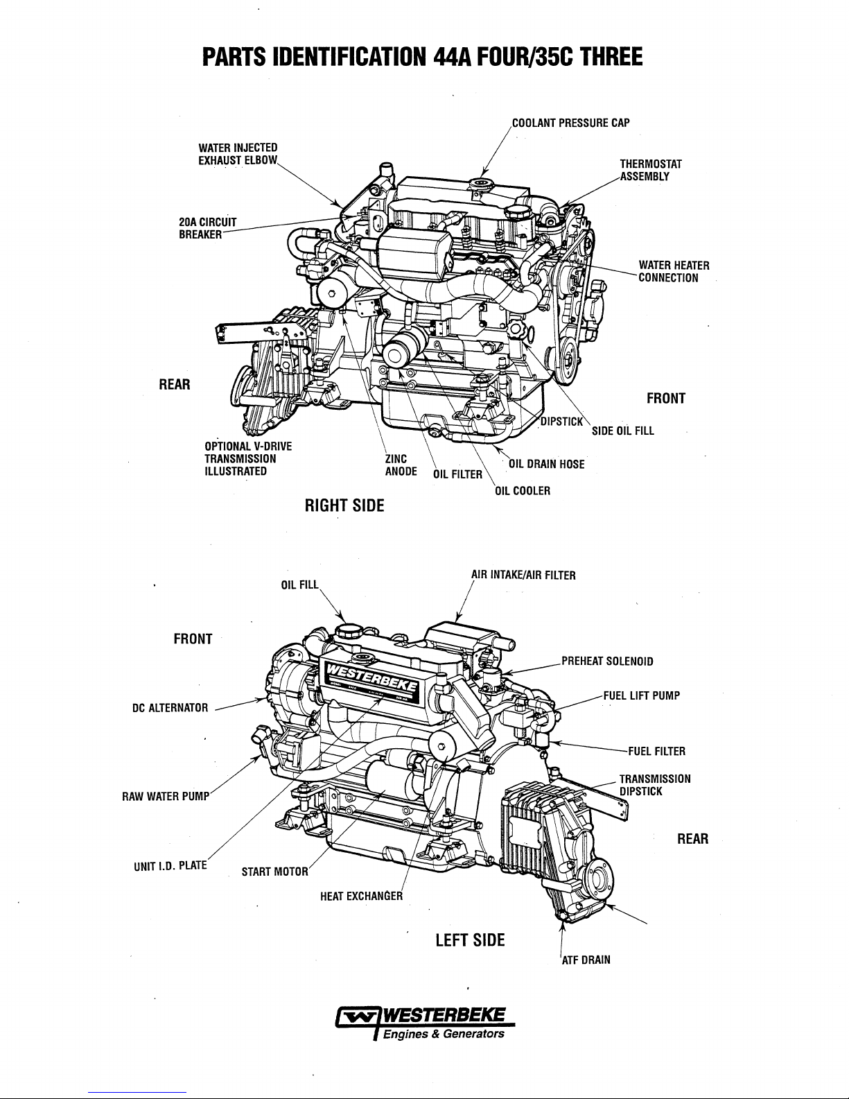
PARTS
IDENTIFICATION
44A
FOUR/35C
THREE
20ACIRCUIT
BREAKER
REAR
WATER
INJECTED
EXHAUST
ELBOW
RIGHT
\
SIDE
ZINC
ANODE
OIL
FILTER
COOLANT
OIL
COOLER
PRESSURE
CAP
SIDE
THERMOSTAT
ASSEMBLY
WATER
HEATER
CONNECTION
FRONT
OIL
FILL
DC
ALTERNATOR
RAW
WATER
UNIT
I.D.
FRONT
PUMP
PLATE
START
OIL
FILL
MOTOR
LEFT
AIR
INTAKE/AIR
SIDE
FILTER
PREHEAT
ATFDRAIN
SOLENOID
FUEL
FILTER
REAR
Engines & Generators
Page 9

INTRODUCTION
This WESTERBEKE Diesel Engine
WESTERBEKE's
technology.
dependable performance of our engines
Thank
you
In
order
to
important that
manual
ual
out.
nearest WESTERBEKE dealer
This
provided
WESTERBEKE
equipment, contact your WESTERBEKE dealer
WESTERBEKE'S installation
is
designed
carefully
Should your engine require servicing, contact your
is
your operators
and
WARRANTY
Your
WESTERBEKE
folder.
If,
after
form
you
have
registering your
writing
serial number
with
Customer
'~/WESTERBEKE
Customer Identification
MR.
ENGINE
MAIN STREET
HOMETOWN,
Model
35C
Expires
10/16/98
long
years of experience and advanced
We
take
great pride
for selecting WESTERBEKE.
get
the
full
use
and
you
operate and maintain it
to
help
you
and
observe
a technical
dealer.
all
the safety precautions through-
manual. A parts
manual
If
you
PROCEDURES
Warranty
60
days
of submitting the
not
received a customer identification card
warranty,
model
and
commission
please contact
information, including
Identification
,
OWNER
USA
THREE
is
a product of
in
the
superior durability
and
generators.
benefit from your
correctly.
do
this.
Please
for
assistance.
catalog
is
available
are
planning
manual.
is
included
date.
to
in
Warranty
the
factory
the
Card
Ser.
#UOOOO-D802
from
engine,
This
read
this
is
also
your
install
this
for
a separate
Registry
in
engine's
and
it
is
man-
PRODUCT
Product software, (technical data, parts lists,
brochures and catalogs), provided
WESTERBEKE
WESTERBEKE
CONTENT
RANTIES OR REPRESENTATIONS WITH RESPECT
THERETO, INCLUDING ACCURACY,
COMPLETENESS
BE
liABLE
INCURRED
OF
THE FURNISHING OR USE
WESTERBEKE customers should keep
span
and
the
product software.
WESTERBEKE products, whether
other suppliers, must
sively
not
only
representatives of WESTERBEKE or
be
consulted
product software being consulted
NOTES,
As
this
maintenance schedules,
engine, critical information
CAUTIONS,
NOTE:
A
observed,
your
SOFTWARE
manuals,
from
sources other
are
not within WESTERBEKE's
CANNOT
OF
SUCH
FOR
ANY
IN
CONNECTION WITH OR ARISING
between printings of WESTERBEKE product software
unavoidable existence of earlier
The
as
the
definitive authority
makes
good sense but
to
determine
CAUTIONS
manual
An
CAUTION:
takes
and
WARNINGS.
operating procedure essential to note.
Procedures
can
result
BE
RESPONSIBLE FOR THE
SOFIWARE, MAKES NO WAR-
TIMEliNESS
THEREOF
product software provided
not
AND
you
AND
WILL
TYPE
OF
DAMAGE
OF
SUCH SOFIWARE.
from
and cannot
the
be
on
the
is
imperative
accuracy
by
the
relied
respective
the
and
WARNINGS
through
and
in
the
the
operating procedures,
troubleshooting of your
will
be
highlighted
An explanation
which,
if
damage
or
in
WESTERBEKE
WESTERBEKE
supplier
customer.
not
destruction
engine.
control.
IN
NO
EVENT
OR INJURY
mind
the
time
with
upon
exclu-
product.
that
appropriate
in
currentness of
marine
by
NOTES,
follows:
strictly
than
OR
OUT
or
It
question
the
of
The WESTERBEKE engine serial number
meric
number that
ufacture of your WESTERBEKE
date
code
is
consists of a character followed
acter indicates
D=1990s),
and
manufacture.
the
the
second
can
assist
in
determining
placed
at
the
end of
the
by
the
decade (A=1960s, B=1970s,
first
number represents
and
third
numbers
engine.
engine serial number
three
represent
is
The
numbers.
the
year
an
alphanu-
the
date of
manufacturer's
The
char-
C=1980s,
in
the
decade,
the
month
of
A
WARNING:
lowed,
can
man-
and
Engines & Generators
3
Procedures
result
in
which,
personal
injury
if
or
not
properly
loss
of
fol-
life.
Page 10
INTRODUCTION
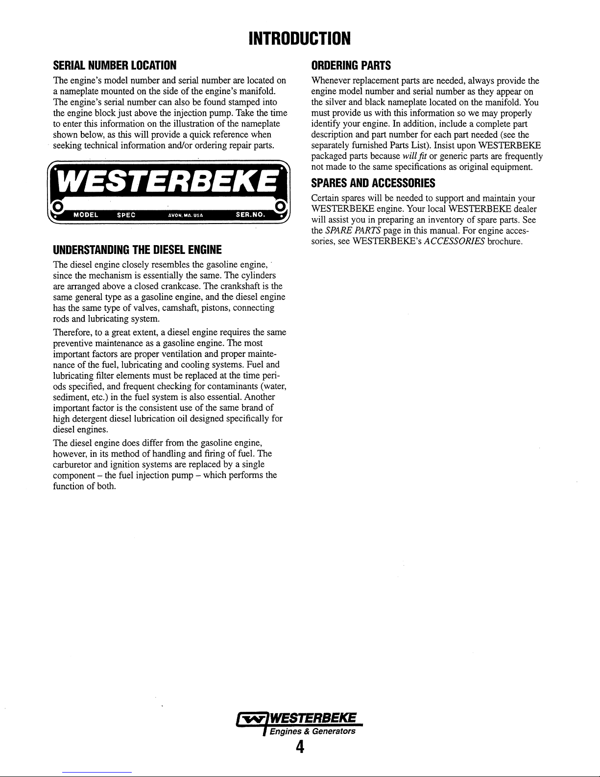
SERIAL
The engine's model number and serial number are located on
a nameplate mounted on the side
The engine's serial number can also be found stamped into
the engine block
to enter this information on the illustration
shown below, as this will provide a quick reference when
seeking technical information and/or ordering repair parts.
C2¥ii4il
o
•
UNDERSTANDING
The diesel engine closely resembles the gasoline engine, .
since the mechanism is essentially the same. The cylinders
are arranged above a closed crankcase.
same general type as a gasoline engine, and the diesel engine
has the same type
rods and lubricating system.
Therefore, to a great extent, a diesel engine requires the same
preventive maintenance as a gasoline engine. The most
important factors are proper ventilation and proper maintenance
lubricating filter elements must be replaced at the time periods specified, and frequent checking for contaminants (water,
sediment, etc.) in the fuel system is also essential. Another
important factor is the consistent use
high detergent diesel lubrication oil designed specifically for
diesel engines.
The diesel engine does differ from the gasoline engine,
however, in its method
carburetor and ignition systems are replaced by a single
component - the fuel injection pump - which performs the
function
NUMBER
LOCATION
of
the engine's manifold.
just
above the injection pump. Take the time
of
the nameplate
:143i
MODEL
of
..
SPEC
THE
of
valves, camshaft, pistons, connecting
the fuel, lubricating and cooling systems. Fuel and
of
both.
AVO.
MA
USA
DIESEL
of
handling and firing
ENGINE
of
SER.NO..
The
crankshaft is the
the same brand
of
fuel. The
of
0
ORDERING
Whenever replacement parts are needed, always provide the
engine model number and serial number as they appear on
the silver and black nameplate located on the manifold. You
must provide us with this information so we may properly
identify your engine. In addition, include a complete part
description and part number for each part needed (see the
separately furnished Parts List). Insist upon WESTERBEKE
packaged parts because
not made to the same specifications as original equipment.
SPARES
Certain spares will be needed to support and maintain your
WESTERBEKE engine. Your local WESTERBEKE dealer
will assist you in preparing an inventory
the
SPARE
sories, see WESTERBEKE's
PARTS
will fit or generic parts are frequently
AND
ACCESSORIES
PARTS
page in this manual. For engine acces-
of
spare parts. See
ACCESSORIES brochure.
Engines & Generators
4
Page 11

ADMIRAL
DESCRIPTION
This manually-operated control panel
KEY
switch
and
RPM
gauge with
meter which measures the engine's running time
1110
hours.
in
ATURE
Fahrenheit,
engine's oil pressure
control circuit
tem's
voltage.
switch
is
in operation.
pushbuttons, one for
RPM
GAUGE:
TERS
REVOLUTIONS
PER
MINUTE
ENGINE
AND
RECALiBRATED
ACCURACY
REAR
OFTHE
The panel also includes a
gauge which indicates water temperature
an
OIL PRESSURE gauge which measures the
in
pounds per square inch, and a
is
turned
VOLTAGE
All
gauges are illuminated
on
The
gauge which measures the sys-
and
remain illuminated while
panel also contains two rubber-booted
PREHEAT
WATER
GRADUATED
ILLUMINATED
TURNED
TEMPERATURE
REGIS·
OF
THE
CAN
BE
FOR
FROM
THE
PANEL.
is
equipped with a
an
ELAPSED TIME
WA1ER
when
and one
TEMPERATURE
ON.
IN
THE
for
DEGREES
WHILE
ENGINE'S
IS
170·
in
1EMPER-
in
the
the
START.
GAUGE:
THIS
FAHRENHEIT
THE
KEY
SWITCH
NORMAL
-190· F (n· -
hours and
degrees
DC
key
engine
GAUGE
AND
IS
OPERATING
88·C).
CONTROL
When
PANEL
the
engine
the water temperature gauge will continue
temperature reading indicated
was
turned
the
key
switch
once again register the engine's true temperature
pOVl:'er
alarm
Panel.
The
the
buzzer
harness.
in a location
to
the
The
buzzer
should
silence
oil
pressure rises
IS
IS
power
when
will
electrical
A
separate
Admiral
necting
electrical
the
buzzer
be
audible
running.
on
and
engine's
is
shut
down
with
by
off
The oil pressure gauge
is
turned
off
is
restored to the
buzzer
with
harness
installer
to
The
operator
will
the
four-pin
installer
where
should
sound
when
is
responsible
is
it
will
when
the
engine
above
OIL
PRESSURE
ATED
IN
POUNDS
ILLUMINATED
ON.
THE
ENGINE'S
PRESSURE
(2.1 -4.2
RANGES
kg/em').
the
key
switch
turned
to
register
the
the gauge before electrical
will
fall
to
The temperature
gauge
when
gauge.
is
supplied
connection
also
responsible
be
dry
it
sound
the
has
15
psi
(1.1
GAUGE:
THIS
PER
SQUARE
WHILE
THE
NORMAL
BETWEEN
for
electrically
on
the
and
where
while
the
ignition
started
kglcm
GAUGE
INCH
KEY
SWITCH
OPERATING
30 -60
with
engine's
for
engine
key
and
2
).
IS
(PSI)
psi
every
installing
it
is
turned
the
GRADU·
AND
IS
TURNED
OIL
off,
last
zero
con-
will
is
IS
HOURMETER:
REGISTERS
TIME,
USED
THE
SCHEDULE.
PREHEAT
ALTERNATOR'S
FUEL
ENGINE'S
OIL
BUTTON
START
STARTER'S
THIS
UNLESS
AT
ELAPSED
AND
SHOULD
AS A GUIDE
MAINTENANCE
SOLENOID
PRESSURE
BUTTON
THE
EXCITER,
ON
GLOW
PLUGS.
ALARM
ENERGIZES
BUTTON:
WHEN
SOLENOID
WILL
THE
PREHEAT
SAME
TIME.
BE
FOR
THE
SWITCH.
THE
PRESSED,
WHICH
NOT
BUTTON
PRESSED,
THE
FUEL
INJECTION
IT
START
OPERATE
liFT
PUMP,
BYPASSES
IN
ADDITION,
BUTTON.
ENERGIZES
CRANKS
ELECTRICALLY
IS
PRESSED
ENERGIZES
PUMP,
AND
THE
ENGINE'S
THE
ENGINE.
THE
THE
THE
THIS
THE
AND
HELD
__
-1\,,,
SWITCH:
POWER
INSTRUMENT
CLUSTER.
~
~
•
,
~
..
,':
.
-.-
•.
:
..
AUTOMATIC
COOLANT
SUPPliED
REACHES
ALARM
Oil
LOCATED
THE
FALL
ING
SIGNAL.
ALARM
TEMPERATURE
WITH
210· F (gg·C),
WHICH
WILL
PRESSURE
ENGINE'S
THE
OFF
TO 5 -10
ALARM.
ALARM:
THE
OIL
psi
SYSTEM
ALARM:
THE
INSTRUMENT
THIS
EMIT
A
AN
OIL
ENGINE'S
PRESSURE.
(0.4 -0.7
IN
THIS
EVENT,
AN
ALARM
PANEL.
SWITCH
WILL
CONTINUOUS
PRESSURE
OIL
GALLERY.
SHOULD
THE
THE
THE
ALARM
kg/em'),
BUZZER
IF
THE
ENGINE'S
CLOSE
SIGNAL.
ALARM
THIS
SWITCH
ENGINE'S
SWITCH
WILL
DC
VOLTMETER:
INDICATES
.BATTERY
SHOULb
HAS
SOUNDING
SWITCH
OIL
WILL
EMIT
PROVIDES
ONLY
TO
PANEL
THE
AMOUNT
IS
BEING
SHOW
13V
BEEN
COOLANT
THE
IS
MONITORS
PRESSURE
CLOSE
SOUND-
A
PULSATING
THE
THE
CHARGED.
TO
14V.
Engines. & Generators
'5
Page 12
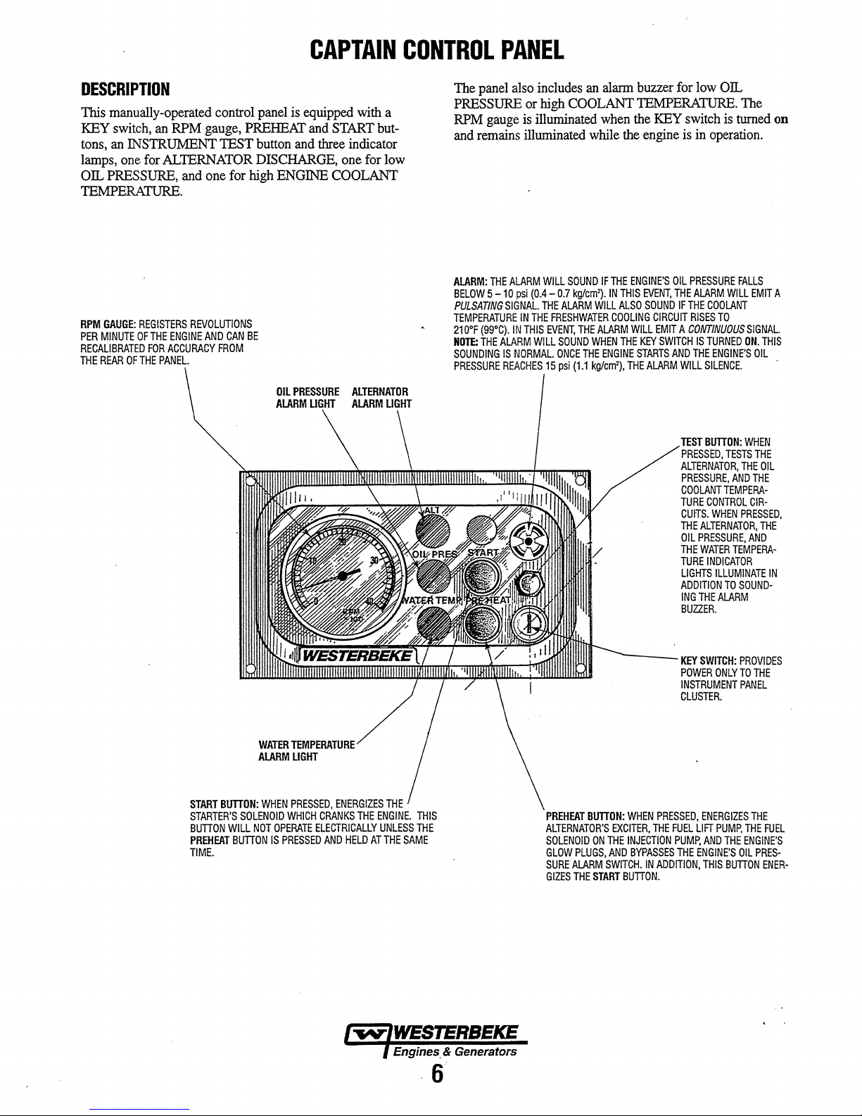
DESCRIPTION
This manually-operated control
KEY
switch,
tons,
an
lamps,
OIL
PRESSURE,
lEMPERATURE.
RPM
GAUGE:
PER
MINUTE
RECALIBRATED
THE
REAR
an
RPM
INSTRUMENT
one
for
ALlERNATOR
and
REGISTERS
OF
FOR
OF
THE
THE
ENGINE
ACCURACY
PANEL.
REVOLUTIONS
gauge,
1EST button
one for
AND
CAN
FROM
panel
is
equipped
PREHEAT
and
DISCHARGE,
high
ENGINE
BE
CAPTAIN
with
and
START
three
indicator
one
CONTROL
a
but-
for
low
COOLANT
PANEL
The
panel
also
PRESSURE
RPM
and
remains
ALARM:
BELOW 5 -10
PULSATING
TEMPERATURE
210°F
(99°C).
NOTE:
THE
SOUNDING
PRESSURE
gauge
THE
ALARM
SIGNAL.
IN
ALARM
IS
NORMAL.
REACHES
or
is
illuminated
psi
IN
THIS
includes
high
COOLANT
illuminated
WILL
SOUND
(0.4 -0.7
THE
kg/em').
THE
ALARM
FRESHWATER
EVENT,
SOUND
ONCE
15
psi
THE
(1.1
WILL
an
alarm
when
while
IFTHE
WILL
ALARM
WHEN
THE
ENGINE
kg/em'),
buzzer
lEMPERATURE.
the
KEY
the
engine
ENGINE'S
EVENT,
SOUND
CIRCUIT
WILL
EMIT
KEY
SWITCH
STARTS
ALARM
OIL
AND
IN
THIS
ALSO
COOLING
THE
THE
for
low
OIL
switch
is
is
in
operation.
PRESSURE
THE
ALARM
IF
A
WILL
TEST
PRESSED,
ALTERNATOR,
PRESSURE,
COOLANT
TURE
CUITS.
THE
OIL
THE
TURE
LIGHTS
ADDITION
ING
BUZZER.
WILL
THE
COOLANT
RISES
TO
CONTINUOUS
IS
TURNED
THE
ENGINE'S
SILENCE.
BUTTON:
TESTS
AND
TEMPERA-
CONTROL
WHEN
ALTERNATOR,
PRESSURE,
WATER
TEMPERA-
INDICATOR
ILLUMINATE
TO
THE
ALARM
The
turned
on
FALLS
EMIT
A
SIGNAL.
ON.
THIS
OIL
WHEN
THE
THE
OIL
THE
CIR-
PRESSED,
THE
AND
IN
SOUND-
START
BUTTON:
STARTER'S
BUTTON
PREHEAT
TIME.
SOLENOID
WILL
BUTTON
WATER
ALARM
WHEN
NOT
OPERATE
IS
TEMPERJlTI
LIGHT
PRESSED,
WHICH
CRANKS
ELECTRICALLY
PRESSED
AND
ENERGIZES
THE
HELD
THE
ENGINE.
UNLESS
AT
THE
THIS
THE
SAME
Engines, & Generators
~---
PREHEAT
BUTTON:
ALTERNATOR'S
SOLENOID
GLOW
SURE
GIZES
ON
PLUGS,
ALARM
THE
START
EXCITER,
THE
AND
SWITCH.
WHEN
PRESSED,
THE
INJECTION
BYPASSES
IN
ADDITION,
BUTTON.
KEY
SWITCH:
POWER
ONLY
INSTRUMENT
CLUSTER.
ENERGIZES
FUEL
LIFT
THE
ENGINE'S
PUMP,
AND
THIS
THE
PUMp,
PROVIDES
TO
THE
PANEL
THE
THE
ENGINE'S
OIL
PRES-
BUTTON
FUEL
ENER-
·6
Page 13
DIESEL
FUEL,
ENGINE
OIL
AND
ENGINE
COOLANT
DIESEL
Use fuel that meets the requirements
2-D
Care
Use only clean diesel fuel! The clearance
in your fuel injection pump is very critical; invisible dirt particles which might pass through the filter can damage these
finely finished parts.
keep it clean. The best fuel can
careless handling
that the fuel going into the tank for your engine's daily use is
clean and pure, the following practice is advisable:
Purchase a well-known brand
Install and regularly service a good, visual-type fuel
filter/water separator between the fuel tank and the engine .
. The
filters.
ENGINE
Use a heavy duty engine oil with an API classification
or CG-4
hours
thereafter. For recommended oil viscosity, see the following
chart:
A
FUEL
(ASTM), and has a cetane rating
Of
The
Fuel
Supply
It
is important to buy clean fuel, and
be
or
improper storage facilities.
of
Raycor 500
FG
or 900
FG
are good examples
OIL
or
better. Change the engine oil after an initial 50
of
break-in operation, and every 100 hours
Operating
41° -68°F
CAUTION:
engine
additives
to
produce
Above
68°F
Below
41°F
oil
to
mix.
of
different
properties
Temperature
(20°C)
(5 -20°C)
(5°C)
Do
not
allow
Each
brand
brands
harmful
SAE
SAE
SAE
two
contains
could
or
specification
of#45
or better.
of
the components
rendered unsatisfactory by
fuel.
Oil
Viscosity
30,
10W-30
20,
10W-30
to
10W-30
or
your
more
its
react
engine.
or
brands
own
in
of
To
assure
of
of
operation
or
15W-40
or
15W-40
15W-40
of
additives;
the
mixture
such
of
Class
CF
ENGINE
WESTERBEKE recommends a mixture
and
chemicals that can corrode internal engine surfaces.
The antifreeze perfonns double duty. It allows the engine to
run at proper temperatures by transferring heat away from
the engine to the coolant, and lubricates and protects the
cooling circuit from rust and corrosion. Look for a good
quality antifreeze that contains Supplemental Cooling
Additives
anced, crucial to long tenn protection.
The distilled water and antifreeze should
being poured into the cooling circuit.
NOTE:
antifreeze that is now available.
Antifreeze mixtures will protect against an unexpected freeze
and they are beneficial to the engine's cooling system. They
retard rust and add to the life
Antifreeze
Freezing
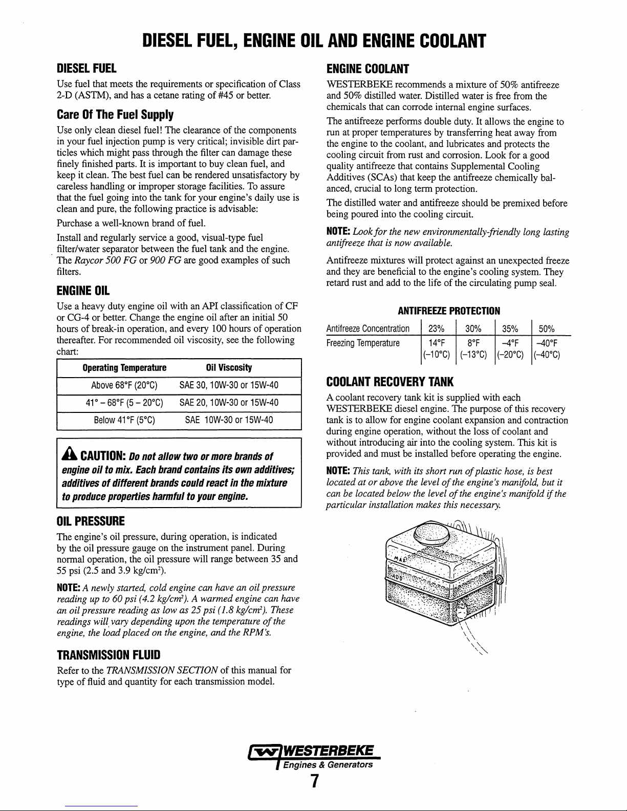
COOLANT
A coolant recovery tank kit is supplied with each
WESTERBEKE diesel engine. The purpose
tank is to allow for engine coolant expansion and contraction
during engine operation, without the loss
without introducing air into the cooling system. This kit is
provided and must be installed before operating the engine.
NOTE:
located at or above
can
particular installation makes this
COOLANT
of
50% antifreeze
50% distilled water. Distilled water is free from the
(SCAs) that keep the antifreeze chemically bal-
be
premixed before
Look for
Temperature
This
be
located below
the
new environmentally-friendly
ANTIFREEZE
Concentration
RECOVERY
tank,
with
its
the
the
of
PROTECTION
23%
14°F
(-10°C)
TANK
short
run
level
of
the
level
of
long
the circulating pump seal.
30%
8°F
(-13°C)
of
engine's
the
necessary.
35%
-4°F
(-20°C)
of
of
coolant and
plastic
hose,
manifold,
engine's manifold
50%
-40°F
(-40°C)
this recovery
is best
lasting
but it
if
the
OIL
PRESSURE
The engine's oil pressure, during operation, is indicated
by the oil pressure gauge on the instrument panel. During
nonnal operation, the oil pressure will range between 35 and
55 psi (2.5 and 3.9 kglcm
NOTE:
A newly started, cold engine
reading
an
readings
engine,
up
to
oil pressure
will.
the
load placed on
60
psi (4.2 kglcm
reading
vary depending
TRANSMISSION
Refer to the TRANSMISSION SECTION
type
of
fluid and quantity for each transmission model.
2
).
as
low
FLUID
can
2
).
A warmed engine
as 25 psi (1.8 kglcm
upon
the
the
engine,
have
an
oil pressure
temperature
and
the
RPM's.
of
this manual for
can
have
2
).
These
of
the
Engines & Generators
7
Page 14

PREPARATIONS
PREST
ART
INSPECTION
Before starting your engine for the first time
longed layoff, check the following items:
D Check the engine oil level. Add oil to maintain the level
at the high mark on the dipstick.
D Turn on the fuel supply, then check the fuel supply and
examine the fuel filter/water separator bowl for contaminants.
D Check the transmission fluid level.
NOTE:
Refer to the previous page
transmission fluid.
for
or
after a pro-
fue~
oil
and
FOR
INITIAL
PLASTIC
START-UP
RECOVERY
TANK
CAP
D Check the
and battery cable connections. Make certain the positive
( +) battery cable is connected to the starter solenoid and
the negative
stud (this location is tagged).
DC
electrical system. Inspect wire connections .
(-)
cable is connected to the engine ground
D Check the coolant level in both the plastic recovery tank
and at the manifold.
NOTE:
If
the engine
refer to the
COOLING SYSTEM section
has
not
yet
been filled with coolant,
of
this manual.
D Visually examine the engine. Look for loose or missing
parts, disconnected wires, and unattached hoses. Check
the threaded connections and engine attachments.
D Make certain there is proper ventilation around the
engine. An ample supply is necessary for proper engine
performance.
D Make sure the mounting installation is secure.
D Ensure the propeller shaft is securely attached to the
transmission.
D Open the through-hull and prime the raw water intake
strainer. Inspect the raw water supply.
:.'\Il>'~~
OIL
FILL
CAP
Engines & Generators
8
Page 15

STARTING/STOPPING
PROCEDURE
THE
STARTING
The
44N35Cdiesel
The start circuitry
must be depressed for the time specified in the preheat chart.
Then, while keeping the PREHEAT button engaged, the
START button
Starting
1.
Place the transmission in neutral and advance the throttle
control to slightly open.
A
CAUTION:
in
neutral.
damage
vessels
2. Tum the KEY SWITCH to the
3. Depress the PREHEAT switch. The voltrrieter,
lights, gauges, meters and fuel solenoid will be activated.
The PREHEAT switch should be depressed in accordance with the following chart:
SYSTEM
engine has a 12V DC electric starter.
is
designed so that the PREHEAT button
is
depressed to crank the engine.
Procedure
Make
certain
Starting
to
your
nearby.
in
gear
transmission,
the
transmission
could
result
your
boat,
ON
position (2 o'clock).
in
serious
and
is
panel
TemperatureJPreheat
Atmospheric
41°F(5°C)
41°F(5°C)
23°F(-5°C)
Limit
NOTE:
The START button will not energize unless the PRE-
HEAT button
activates the glow plugs in the cylinder head so use the
HEAT intermittently to avoid overheating the glow plugs.
4. While still depressing the PREHEAT button, depress the
START button. This will engage the starter solenoid.
Upon engine starting, release the START switch. Do not
release the PREHEAT switch until the oil pressure reaches
5 - 10 psi. Then as long as the high water temperature and
low oil pressure protective circuits do not activate, the engine
will remain energized and continue to run.
Temperature
or
higher
to
23°F
(-5°C)
or
lower
of
continuous
is
use
depressed. Depressing the PREHEAT button
Preheating
Approx.
Approx.
Approx.
30
seconds
10
seconds
15
seconds
20
seconds
before
Time
cranking
PRE-
5. Should the engine not start when the START button
depressed for 10 to 20 seconds, release both buttons and
30 seconds; repeat the procedure above and preheat
wait
longer. Never
A
CAUTION:
the
engine
system
the
cooling
enter
filling
pump
system
the
manifold
from
happening
through-hull
correcting
Engine
damage
warrantable
in
mind.
6.
Once the engine starts, check the instruments for proper
oil pressure and battery charging voltage.
NOTE:
engine
NOTE:
engine. Depressing the
second intervals will help stabilize the engine rpm until
the engine operating temperature reaches
(77 - 88°C) and a propeller load is applied
When the engine
depressed, a charging load on the
discernible.
Starting
Make sure the lubricating oil
temperature.
SAE
30, lOW-30, or 15W-40.
The battery should be fully charged to minimize voltage drop.
Use a sufficient amount
Temperature/Preheat chart elsewhere in this section.
run
the starter
Prolonged
starting
is
pumping
engine's
once
the
with
raw
during
cylinders
the
exhaust
by
shutoff,
cause
can
raw
cranking.
closing
draining
of
resulting
issue;
the
owner/operator
Never attempt to engage the starter while the
is
running.
Some unstable running may occur
is running and the PREHEAT button
Under
Cold
Conditions
Use oil with an API Specification
of
for
more than 30 seconds.
cranking
result
water.
water
by
system
the
the
excessive
from
in
the
This
may
through
This
way
fills.
raw
the
exhaust
raw
water
intervals
engine
happen
the
raw
of
the
Prevent
water
supply
engine
entry
exhaust
raw
water
exhaust
muffler,
should
in
a cold
PREHEAT button
is
appropriate for the prevailing
preheat to aid in starting. See the
for
170
to
DC
alternator will be
of
is
without
because
water
can
this
and
cranking.
is
not
a
keep
this
10-
15
-190°F
the engine.
CF
or CG-4,
is
NOTE:
When starting:
A voltage drop will occur
when the preheat button
is
depressed.
Stopping
To
stop the engine, bring the throttle to
place the transmission in neutral. Allow the engine to idle for
a few moments to stabilize temperatures. Turn the engine off
using the stop control cable.
an
optional fuel shut off solenoid, turn off the key switch at
the control panel.
NOTE:
Make certain this key switch is
( 12 o'clock).
discharge.
operator
of
key from the key switch after stopping the engine.
Engines & Generators
of
preventing the battery from discharging
9
Procedure
an
idle position and
If
your engine
If
the key switch
An
engine alarm buzzer
this condition (key switch ON). The best method
is
left
is
is
equipped with
in
the OFF position
ON,
the battery will
provided to warn the
is
to remove the
Page 16

WARNING
ALTERNATOR
The Captain Control Panel indicates alternator low discharge
with a red warning light.
The Admiral Control
performance
WARNINGS
Panel uses a voltmeter to monitor the
of
the alternator.
'
LIGHTS,
ALARMS & CIRCUIT
BREAKER
LOW
OIL
PRESSURE
A low oil pressure alarm switch is located off the engine's
oil gallery. This switch's sensor monitors the engine's oil
pressure. Should the engine's oil pressure fall to
(0.4 - 0.7 kg/cm2), this switch will activate a pulsating alarm.
ALARM
SWITCH
5 - 10 psi
COOLANT
A coolant temperature switch is located on the thermostat
housing. This switch will activate a continuous alarm
coolant's operating temperature reaches approximately
(99°C). .
COOLANT
TEMPERATURE
SWITCH
TEMPERATURE
SWITCH
SENDORS
The coolant temperature and oil pressure sendors are not
installed in the
Both sendors are, however, included in the Admiral
Instrument
These sendors (with connecting gauges) can be added as
accessories to either engine at any time and are easily
installed to the prewired engine.
44N35C engines as standard equipment.
Panel Kit.
if
the
2100P
DlL
PRESSURE
/
/
ENGINE
The
DC
mounted manual reset circuit breaker
Excessive current draw or electrical overload anywhere in
the instrument panel wiring
breaker to trip. In this event most engines will shut down
because the opened breaker disconnects the fuel supply.
this should occur, check and repair the source
After repairing the fault, reset the breaker and restart the
engine.
SWITCH
SENDOR
CIRCUIT
harness on the engine is protected by an engine-
BREAKER
or
engine wiring will cause the
(20 amps DC).
of
the problem.
If
Engines &
10
Generators
Page 17

ENGINE
BREAK-IN
PROCEDURE
DESCRIPTION
Although your engine has experienced a minimum
hour
of
test operations at the factory to make sure accurate
assembly procedures were followed and that the engine operated properly, a break-in time is required. The service life
your engine is dependent upon how the engine is operated
50
hours
of
and serviced during its initial
Breaking-in a new engine basically involves seating the piston rings to the cylinder walls. Excessive oil consumption
and smoky operation indicate that the cylinder walls are
scored, which is caused by overloading the engine during the
break-in period.
Your new engine requires approximately
conditioning operation to break in each moving part in order
to maximize the performance and service life
Perform this conditioning carefully, keeping in mind the fol-
lowing:
1.
Start the engine according to the
use.
50
STARTING
DURE section. Run the engine at fast idle while checking
that all systems (raw water pump, oil pressure, battery
charging) are functioning.
2. Allow the engine to warm up (preferably by running at
fast idle) until the water temperature gauge moves into
the
130 - 1400P (55 - 60°C) range.
hours
of
the engine.
PROCE-
of
of
one
of
initial
3. While using the vessel, run the engine at various engine
speeds for the first 25 hours. Avoid prolonged periods
idling.
4. Avoid rapid acceleration, especially with a
S.
Use caution not to overload the engine. The presence
grey or black exhaust and the inability
reach its full rated speed are signs
6. During the next 25 hours, the engine may be operated at
varying engine speeds, with short runs at full rated rpm.
Avoid prolonged idling during this break-in period.
CHECK
LIST
of
cold engine.
of
the engine to
an overload.
of
of
o Monitor the control panel gauges.
o Check for leaks
of
fuel and engine oil.
o Check for abnormal noise such as knocking, friction,
vibration and blow-back sounds.
o Confirm exhaust smoke:
When the engine is cold - white smoke.
When the engine is warm - almost smokeless.
When the engine is overloaded - some black smoke and soot.
NOTE:
See
the
TRANSMISSION section
break-in information
on
your transmission.
of
this manual for
a
Engines & Generators
11
Page 18

THE
DAILY
OPERATION
CHECK
Follow this check list each day before starting your engine.
LIST
D Record the hounneter reading in your log (engine hours
relate to the maintenance schedule.)
D Visually inspect the engine for fuel, oil, or water leaks.
D Check the oil level (dipstick).
D Check the coolant level in the coolant recovery tank.
Periodically check the manifold coolant level.
D Check the transmission fluid level.
D Check your diesel fuel supply.
D Look for clean fuel in the fuel filter/water separator trans-
parent bowl.
D Check for loose wires at the alternator and make sure its
mounting is secure.
D Check the starting batteries (weekly).
D Check drive belts for wear and proper tension (weekly).
D Check the raw water pump to make sure its mounting is
secure.
STARTING
NOTE:
manual for
1. Put the transmission in neutral, throttle advanced.
NOTE:
neutral safety switch through which
energizing circuit passes.
transmission
energize.
2.
Tum
3. Depress PREHEAT
4. While pressing PREHEAT, push
fires, release
S.
Hold PREHEAT until the oil pressure reaches
and/or the alarm shuts off.
NOTE:
engine.
temperature
NOTE:
then
6. Allow a few minutes for the engine to warm at a comfortable rpm (approximately
rpm, and get underway.
THE
ENGINE
See
STARTING/STOPPING PROCEDURE
more
detailed instructions.
Hydraulically operated transmissions have a
the
starter solenoid
This
switch
is
open
is
in
gear
so
the
starter solenoid will not
the KEY to the
START.
Some
unstable running may occur
This
condition should abate as normal operating
is
Should
repeat
the
ON
position (2 o'clock).
(10 to
15
reached and loads
the
engine
fail
to
above
procedure,
1000 rpm), then reduce the
seconds).
START. As the engine
in
are
applied.
start,
wait
and PREHEAT
when
a cold
30
seconds,
in
15
this
the
psi
longer.
Engines & Generators
12
Page 19

MAINTENANCE
In order to use this Maintenance Schedule, it will be necessary to log your engine hours.
record your engine hours by running time.
NOTE:
Many
of
the following maintenance procedures are
simple but others are more difficult
expert knowledge
of
a service mechanic.
Use your engine hourrneter or
and
may require the
SCHEDULE
A
WARNING:
while
the
equipment
correct
terminals
electrical
tools
Never
engine
is
running.
such
as
goggles
for
each
when
servicing
equipment.
job.
attempt
Wear
and
Disconnect
any
of
to
perform
the
proper
gloves,
the
the
engine's
any
and
battery
service
safety
use
the
DC
SCHEDULED
MAINTENANCE
Fuel
Supply
Fuel/Water
Engine
Coolant
Transmission
Drive
Visual
Fuel
Starting
(and
Engine
Heat
Fuel/Water
Exhaust
Engine
Throttle
Control
Adjust
Raw
Separator
Oil
level
level
Fluid
Belts
Inspection
Filter
Batteries
House
Batteries)
Oil
and
Exchanger
Separator
System
Hoses
and
Transmission
Cable
Engine
Water
Pump
of
Filter
Zinc
Idle
level
Engine
Anode
Speed
CHECK
EACH
DAY
0
0
0
0
0
0
weekly
0
0
weekly
HOURS
OF
OPERATION
50
100
250
500
750
1000
1250
NOTE:
Keep
engine
surface
clean.
Dirt
oil
will
cool.
0
inhibit
the
engine's
ability
0 0 0 0 0
to
remain
and
0 0 0 0 0 0 0
0 0 0
0 0
0
0 0 0 0 0 0
0 0
0 0
0 0 0 0 0 0
0 0
0
0
0 0 0
0
0
Diesel
No.2
Check
for
if
necessary).
Oil
level
should
dipstick.
Check
at
recovery
Add
coolant
Fluid
level
on
dipstick.
Inspect
for
and
adjust
Check
for
and
electrical
Check
for
Change
at
Check
electrolyte
and
make
excessive
Initial
engine
change
both
Inspect
zinc
exchanger
Change
filter
Initial
check
Inspect
for
tion.
Check
corrosion
replace
as
tig
ht.
Check
Hose
should
spongy.
Check
Check
for
Lubricate
Adjust
Remove
gasket,
and
Lubricate
to
the
cam
seals
with
750 -1000
when
MAINTENANCE
rating
water
and
indicate
if
needed.
should
indicate
proper
if
needed.
fuel,
oil
and
connections.
loose
belt
50
hours
levels
sure
connections
corrosion.
oil & filter
every
anode,
end
of
zinc
every
at
50
hours,
leaks.
Check
the
exhaust
buildup
necessary.
casti
ng
be
hard & tight.
and
loose
fittings,
WD-40
pump
and
cover
(the
shaft
reassembling.
of
45
dirt
between
tank;
if
tension
Check
water
tension.
then
every
change
100
hours.
replace
anode
200
hours.
anti-siphon
elbow
on
inside
Check
integ
tighten
cotter
or
rpm
cover
for
can
turn,
cetane
in
every
then
rity.
equivalent.
and
DESCRIPTION
empty,
between
(3/8"
all
wear.
or
higher.
fuel
(drain/replace
MAX.
check
MAX
to
1/2"
belt
edges
leaks.
Inspect
Keep
bolts & nuts
250
hours.
50
operating
are
very
at
50
if
needed.
debris.
every
250
valve
for
carbon
passages;
that
all
connections
Replace
hose
clamps.
pins,
etc.
inspect
Check
but
not
and
LOW
at
manifold.
and
deflection)
for
wear.
wiring
hours
tight.
Clean
hours,
then
Clear
the
hours.
opera-
and/or
clean
and
if
soft
or
the
impeller,
the
bearings
wobble).
( continued)
filter
on
LOW
tight.
off
heat
are
--+
Engines & Generators
13
Page 20

NOTE:
Use
engine
the
hours by
MAINTENANCE
engine
hourmeter
running
time.
gauge
to
log
SCHEDULE
your
engine
hours
or
record
your
SCHEDULED
MAINTENANCE
Coolant
System
DC
Alternator
Air
Intake
Filter
Transmission
Engine
Transmission
Damper
*Fuellnjectors
*Starter
*Preheat
Lubricate
with
Transmission
Plate
Motor
Circuit
*Engine
*
*Heat
Fluid
Cylinder
Compression
Adjust
the
Valve
Exchanger
Panel
"Lockeze"
Oil
Cooler
Clearances
Key
Switch
CHECK
EACH
DAY
HOURS
OF
OPERATION
50
100
250
500
750
D D
D D
D D D D D D
D
D D
D D
D D
D
D D
D D D D D D
D D D
D
1000
D
D
D
D D
1250
Drain.
priate
Check
D
bracket;
Clean
Remove;
tested.
Chattering
of
damper
Check
spray
Check
and
pinion
Check
clean
compound
Check
Adjustments).
Adjust
ADJUSTMENTS).
Remove.
tested.
At
Initial
300
MAINTENANCE
flush.
and
antifreeze
DC
charge
tighten
every
100
have
at
plate
and
adjust
condition
solenoid
lubricate.
drive.
operation
glow
plugs.
on
compression
Valve
Clearances
have
first
100
hours.
fluid
change
hours
or
refill
cooling
mix.
from
alternator.
electrical
operating
professionally
idle
wear.
(see
and
Clean
of
threads.
professionally
at
winterizing.
and
low
Remove
injection
ENGINE
motor
and
lubricate
preheat
Reinstall
pressure
(see
then
each
at
25
connections.
rpms
hours.
DESCRIPTION
system
with
appro-
Check
mounting
hours.
cleaned
and
pressure
is
an
indication
and
replace.
opening
for
pressure
ADJUSTMENTS).
corrosion.
solenoid.
with
anti-seize
and
timing
ENGINE
cleaned
year
then
Remove
the
starter
Remove
(see
and
pressure
at
winterizing.
every
and
motor
and
Engine
*WESTERBEKE
recommends
this
service
be
performed
by
an
authorized
Engines & Generators
14
mechanic.
Page 21

COOLING
SYSTEM
DESCRIPTION
Westerbeke marine diesel engines are designed and equipped
for fresh water cooling. Heat produced in the engine by combustion and friction is transferred to fresh water coolant
which circulates throughout the engine. This circulating fresh
water coolant cools the engine block, its internal moving
parts, and the engine oil. The heat is transferred externally
from the fresh water coolant to raw water by means
exchanger, similar in function to an automotive radiator. Raw
water flows through the tubes
fresh water coolant flows around the tubes; engine heat trans-
ferred to the fresh water coolant is conducted through the
tube walls to the raw water which is then pumped into the
exhaust system where finally it is discharged overboard. In
other words, the engine is cooled by fresh water coolant, this
coolant is cooled by raw water, and the raw water carries the
transferred heat overboard through the exhaust system. The
fresh water coolant and raw water circuits are independent
each other. Using only fresh water coolant within the engine
allows the cooling water passages to stay clean and free from
harmful deposits.
FRESH
NOTE:
WATER
Refer
to
COOLING
the
ENGINE COOlANT section for
ommended antifreeze and water mixture
fresh water
Fresh water coolant is pumped through the engine by a circulating pump, absorbing heat from the engine. The coolant
then passes through the thermostat into the manifold, to the
heat exchanger where it is cooled, and returned to the enaine
block via the suction side
coolant.
of
the heat exchanger while
CIRCUIT
to
be
of
the circulating pump. 0
the
used as
of
a heat
of
rec-
the
When the engine is started cold, external coolant flow is prevented by the closed thermostat (although some coolant flow
is bypassed around the thermostat to prevent the exhaust
manifold from overheating). As
thermostat gradually opens, allowing full flow
coolant to flow unrestricted to the external portion
cooling system.
Coolant
A coolant recovery tank allows for engine coolant expansion
and contraction during engine operation, without any significant loss
ing system. This tank should be located at
engine manifold level and should be easily accessible.
CHANGING
The engine's coolant must be changed according to the
Recovery
of
coolant and without introducing air into the cool-
Tank
COOLANT
MAINTENANCE SCHEDULE.
become contaminated, it can lead to overheating problems.
A
CAUTION:
Proper
critical; a substantial
traced
back
to
cooling
To drain
pressure cap and unfasten the drain hose as shown below.
NOTE:
be
out
The
drain petcock
used
to
help
A
WARNING:
Wear
protective
the old engine coolant, loosen the manifold
drain
engine
Beware
gloves.
the engine warms up, the
If
the coolant is allowed to
cooling
number
system
on
system
of
maintenance
engine
corrosion.
the
heat exchanger should also
coolant.
of
the
hot
engine
of
the engine's
or
above the
failures
coolant.
of
can
the
is
be
ENGINE
BLOCK
RELEASE
FROM
DRAIN
THE
THE
THE
OIL
THE
COOLANT
ENGINE
COOLANT
BLOCK
COOLER
FROM
LINE
TO
Engines &
15
OIL
Generators
FILTER
Page 22

COOLING
SYSTEM
Refilling
After replacing
exchanger's coolant petcock. Then pour clean, premixed
coolant
the
NOTE:
When
the
Monitor
the
sure cap.
Remove
coolant
the
flow
After checking for leaks, stop the engine and allow it
Coolant should draw back into 'the cooling system
engine
needed.
RECOVERY
FROM
RECOVERY
NOTE:
pressure
good
the
closes
cap.
coolant passage
coolant within
able
to
and
the
Coolant
the
engine block drain
into
the
manifold
manifold, start
Open
the
air-bleed petcock
a steady flow
petcock and fill
the
coolant
manifold
cap.
into
TO
to
the filler neck
the
cap on the coolant recovery tank
mix
to
halfway between LOW and MAX
Run
the engine
the
recovery tank.
coolll
down.
Cle~
up
COOLANT
TANK
COOLANT
TANK
Periodically check
cap.
Ensure
condition.
Check
any
and
the
engine
of
coolant appears at
the
system until
in
the
and
Add coolant
spilled coolant:
the
the
upper and lower rubber seals
to
ensure
vacuum valve opens and
tightly.
Carry a spare
Check
also
to
ensure
is
clear
so
the
system
is
to
expand and contract
from
the
coolant
recovery
plug,
close
when
the coolant
and
run
on
the
manifold
and
install the manifold pres-
observe
to
the recovery tank if
KEEP
THE
COOLANT
CLEAR
COOL4NT
it
the
manifold
and
the
PASSAGE
EXPANSION
is
at
slow idle.
heat
exchanger.
the
petcock, close
add
as
needed. Fill
and
coolant expansion
PRESSURE
of
/CAP
the
manifold
~~:;-m;;iiiiII
COOLANTRETR4CnON
condition
the
tank.
the
heat
visable
remains
fill
with
and
replace
to
as
the
THERMOSTAT
A thermostat, located near
engine, controls
uously
flows
engine
is
from
flowing
thermostat
As
~e
engine
thermostat
replaced
the
through the closed cooling circuit. When
first
started,
(some coolant
to
prevent the exhaust manifold
warms
is
accessible
easily.
Carry a spare thermostat
the
manifold at
coolant temperature
the
closed thermostat prevents coolant
is
by-passed through a hole in
up,
the thermostat gradually
and
can
be
the
front of
as
the
coolant contin-
from
checked, cleaned, or
and
gasket.
the
the
overheating).
opens.
full.
cool.
are
The
in
in
the
Replacing
Remove
ing
as
ket,
apply
before pressirig it into place.
screws.
Run
the
there
THERMOSTAT
ASSEMBLY
RAW
The
raw
impeller
water source (ocean, lake, or river) through a hose
water strainer. The
through the
the
heat exchanger tubes) where it cools the engine circulat-
ing
fresh water coolant. The raw water
into
the
ing
the
water
discharge pressure.
Raw
The
raw
non-ferrous housing and a neoprene impeller. The impeller
has
flexible vanes which wipe against a curved
within
On
no
lubricant for the
impeller
Raw
water
water) is not present during engine operation. Such
are not warrantable,
raw
water
NOTE:
(seals
chase
the
Thermostat
the
cap
screws
and
disassemble
shown. When installing
a thin coat of sealant
engine
and
check for normal temperatures
are
.no
leaks
at
the
WATER
exhaust gasses. This mixture of exhaust
is
Water
the
account should
COOLING
water
flow
is
created
pump.
This pump draws water directly
raw
raw
water pump
water-injected exhaust
discharged overboard
Pump
water
pump
is
impeller housing, producing
this
imp~ller.
and
impeller cover gasket (an impeller kit)
pump
impeller failures occur
and
flow
is
present at start-up.
the
on
Do
not over-tighten
thermostat housing.
CIRCUIT
by
water passes
to
the
elbow,
by
a self-priming, rotary
pump be
There should always
operators are cautioned
Should a failure occur with
and
bearings), it may
a new pump and rebuild
be
more
the
the
new thermostat
both sides of
a positive displacement
from
heat exchanger (through
is
then discharged
mixing with
the engine's exhaust
the
run
dry
when
the
pump:r
cost efficient
original pump
thermostat
au.d
gas-
the
gasket
the
cap
and
that
TEMPERATURE
SENDOR
[OPTIONAL]
from
the
to
the
the
strainer
and
cool-
gas
and
gas
pump
with
cam
plate
pumping action.
as
water
acts
be
a spare
aboard.
lubricant
failures
to
make sure
internal parts
to
pur-
as a spare.
hous-
raw
(raw
raw
a
as
a
Revised: February 2002
-.¥'
WESTERBEKE
Engines & Generators
16
Page 23

COOLING
SYSTEM
Changing
Close the raw water intake valve. Remove the pump cover
and, with the aid
impeller out
Move the blades to conform to the curved cam plate and
push the impeller into the pump's housing. When
bling, apply a thin coating
gasket.
the
Raw
Water
of
two small screwdrivers, carefully pry the
of
the pump. Install the new impeller and gasket.
Open the raw water intake valve.
Pump
Impeller
of
lubricant to the impeller and
~@
1:
assem-
NOTE:
Also follow
aground.
If
the engine temperature gauge ever shows a higher than
normal reading, the cause may be that silt, leaves or grass
may have been caught up in the strainer, slowing the flow
raw water through the cooling system.
STRAINER
FILTER
the
above procedure after having
I
L~.--.
f ,
~--~
TYPICAL
RAW
Owner
WATER
Installed
INTAKE
STRAINER
run
hard
of
A
CAUTION:
impeller,
cooling
circuit.
they
If
must
They
any
be
often
of
the
found
can
vanes
to
prevent
be
have
found
broken
blockage
in
the
heat
off
in
the
the
exchanger.
Raw
Water
NOTE:
the
strainer will always
A clean raw water intake strainer is a vital component
engine's cooling system. Include a visual inspection
strainer when making your periodic engine check. The water
in the glass should be clear.
Perform the following maintenance after every
operation:
1.
Close the raw water seacock.
2. Remove and clean the strainer filter.
3. Clean the glass.
4. Replace the washer
5. Reassemble and install the strainer.
Open the seacock.
6.
7. Run the engine and check for leaks.
Intake
Always install
Strainer
the
strainer at or below
be
self-priming.
if
necessary.
the
waterline
100 hours
of
of
this
the
of
so
HEAT
EXCHANGER
The heat exchanger is a copper cylinder which encloses a
number
the small copper tubes and the fresh water coolant from the
engine is circulated around the copper tubes. The raw water
removes heat from the fresh water coolant.
of
small copper tubes. Raw water is pumped through
HEAT
EXCHANGER
PETCOCK
HEAT
GASKET
CLEAN
DEBRIS
ZINC
ANODE
EXCHANGER
Engines & Generators
17
Page 24
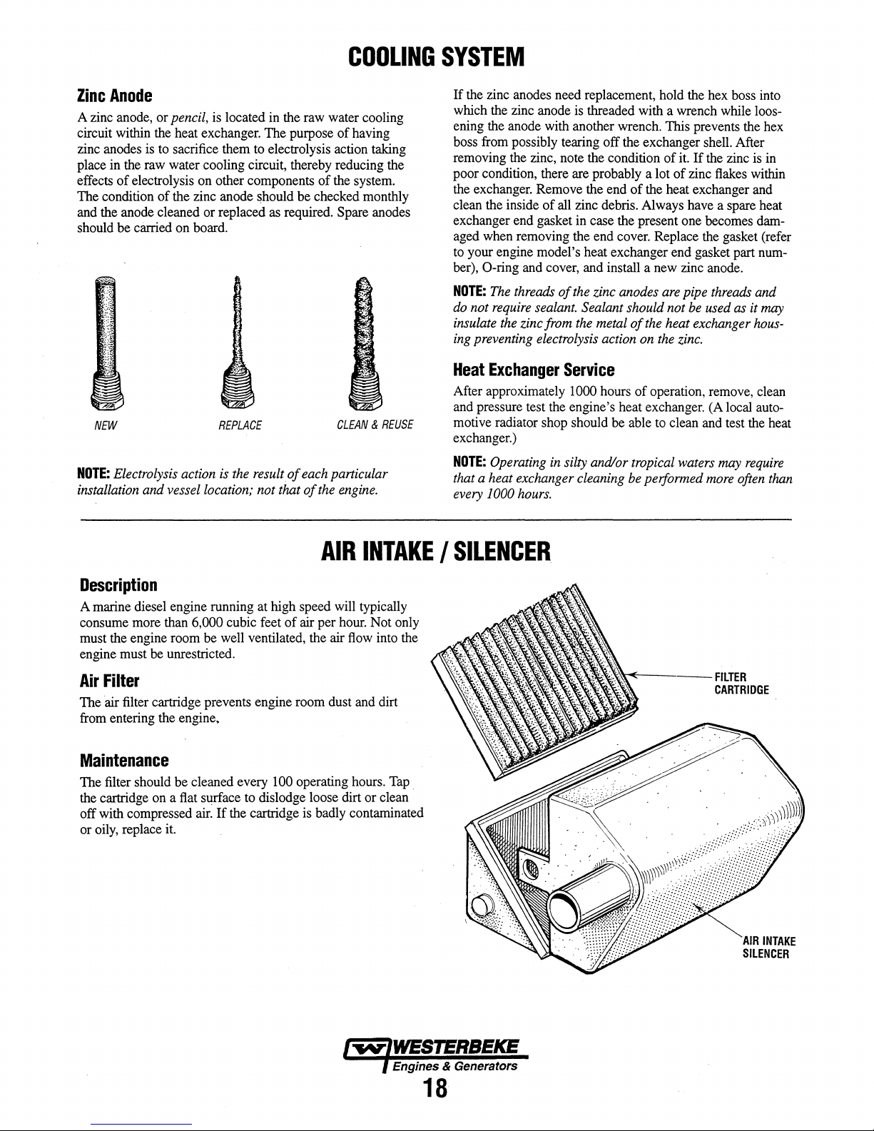
COOLING
Zinc
Anode
~
zi~c
~o~e,
or
pencil, is located in the raw water cooling
CIrCUIt
wIthin the heat exchanger.
zinc
~odes
is to sacrifice them to electrolysis action taking
place
In
the raw water cooling circuit, thereby reducing the
of
effects
The
and the anode cleaned or replaced as required. Spare anodes
should
NOTE:
electrolysis on other components
condition
NEW
Electrolysis action
be
of
the zinc anode should
carned
on
board.
REPLACE
is
installation and vessel location; not that
the
The
purpose
resultof
of
having
of
the system.
be
checked monthly
CLEAN & REUSE
each
particular
of
the
engine.
SYSTEM
If
the zinc anodes need replacement, hold the hex boss into
which the zinc anode is threaded with a wrench while loosening the anode with another wrench. This prevents the hex
boss from possibly tearing
removing the zinc, note the condition
poor condition, there are probably a lot
the exchanger. Remove the end
clean the inside
exchanger end gasket in case the present one becomes
aged when removing the end cover. Replace the gasket (refer
to your engine model's heat exchanger end gasket part number), O-ring and cover, and install a new zinc anode.
NOTE:
The
do
not
require
insulate
ing
Heat
After approximately 1000 hours
and pressure test the engine's heat exchanger. (A local automotive radiator shop should be able to clean and test the heat
exchanger.)
NOTE:
the
preventing electrolysis action
Exchanger
Operating
of
threads
sealant.
zinc from
all zinc debris. Always have a spare heat
of
in
that a heat exchanger cleaning
every
1000
hours.
off
the exchanger shell. After
of
of
the heat exchanger and
the
zinc anodes
are
Sealant should not
the
metal
of
the
heat exchanger
on
the
Service
of
operation, remove, clean
silty and/or tropical
be
performed
it.
If
the zinc is in
of
zinc flakes within
pipe
threads
be
used
as
zinc.
waters
may
require
more
often
dam-
and
it
may
hous-
than
AIR
INTAKE I SILENCER
Description
A marine diesel engine running at high speed will typically
consume more than
must the engine room be well ventilated, the air flow into the
engine must be unrestricted.
Air
Filter
The air filter cartridge prevents engine room dust and dirt
from entering the engine,
6,000 cubic feet
of
air
per
hour. Not only
Maintenance
The filter should
the cartridge on a flat surface to dislodge loose dirt
off with compressed air.
or oily, replace it.
be
cleaned every 100 operating hours. Tap
or
If
the cartridge is badly contaminated
clean .
"'~~~~----FILTER
CARTRIDGE
Engines & Generators
18
Page 25
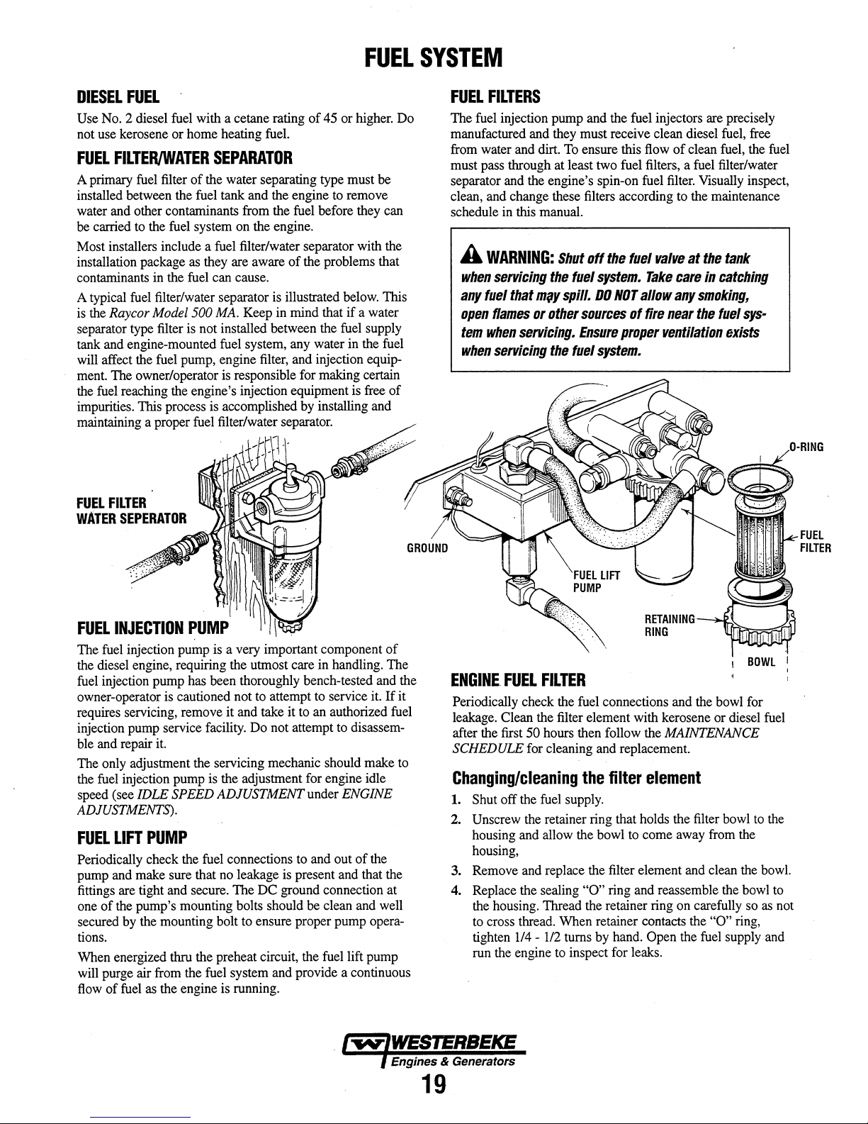
DIESEL
Use
not
FUEL
A primary
installed between the fuel tank and
water
be
Most installers include a
installation package
contaminants
A typical
is
separator
tank
will
ment.
the
impurities.
maintaining a proper
FUEL
No.2 diesel
use
kerosene or home heating
fuel
FILTER/WATER
fuel
filter of the water separating type must be
and
other contaminants from the
carried
to
the
fuel
as
in
the
fuel
fuel
filter/water separator
the
Raycor Model 500 MA.
type
filter
is
and
engine-mounted
affect
the
fuel pump, engine
The owner/operator
fuel
reaching
This
the
engine's injection equipment
process
with a cetane rating of 45 or
SEPARATOR
system
on
the engine.
fuel
filter/water separator with
they are aware of
can cause.
Keep
not installed between
fuel
system,
is
responsible for making certain
is
accomplished
fuel
filter/water
fuel.
the
engine
fuel
before they
the
problems that
is
illustrated
in
mind that if a water
the
any
water in the
filter,
and injection equip-
by
installing
separator.
to
remove
below.
fuel
higher.
is
FUEL
supply
free
and
SYSTEM
Do
can
the
This
fuel
of
FUEL
FILTERS
The
fuel
injection pump and the fuel injectors
manufactured and they must receive clean diesel
from
water
and
dirt.
To
ensure this
must pass through at least
separator
clean,
schedule
A
when
any
open
tem
when
and
the engine's spin-on fuel
and
change these filters according
in
this
manual.
WARNING:
servicing
fuel
that
flames
when
servicing
Shut
the
mlY
spill.
or
other
servicing.
the
fuel
sources
Ensure
fuel
two
off
system.
DO
system.
fuel
the
NOT
proper
flow
filters, a
fuel
Take
allow
of
fire
valve
ventilation
are
of clean
fuel
filter.
Visually inspect,
to
the
at
the
care
in
any
smoking,
near
the
precisely
fuel,
free
fuel,
the
fuel
filter/water
maintenance
tank
catching
fuel
sys-
exists
FUEL
FILTER
WATER
FUEL
The
the
fuel
owner-operator
requires servicing, remove it and take it
injection
ble
The
the
speed (see
ADJUSTMENTS).
FUEL
Periodically check
pump
fittings
one of
tions.
When energized thru the preheat circuit,
SEPERATOR
~
I~~~ION
fuel
injection pump
diesel engine, requiring
injection pump has been thoroughly bench-tested and the
pump
and
repair
only
adjustment
fuel
injection pump
IDLE SPEED
LIFT
and make sure that
are tight and secure. The
the
pump's mounting bolts should
secured
will
flow
by
the
purge air
of
fuel
as
PUMP
is
cautioned not
service
it.
PUMP
the
mounting bolt
from
the fuel system
the
engine
~
~'
~
.:~:~
is a very
facility.
the
servicing mechanic should make
is
the adjustment for engine idle
ADJUSTMENT
fuel
no
is
important component of
the
utmost care in handling. The
to
attempt
Do
not attempt
connections
leakage
DC
to
ensure proper pump
running.
to
service
to
an
authorized
to
under ENGINE
to
and
out of
is
present
ground connection at
and
provide a continuous
be
the
and
clean
fuel
it.
disassem-
the
that
and
well
opera-
lift
pump
If
fuel
the
it
to
ENGINE,
Periodically check the
leakage. Clean the filter element with kerosene or diesel
after the first 50 hours then follow the MAINTENANCE
SCHEDULE
Changing/cleaning
1.
Shut off
2.
Unscrew
housing
housing,
3.
Remove
4.
Replace the sealing
the
housing. Thread the retainer ring
to
cross thread. When retainer contacts
tighten
run
the
FUEL
FILTER
fuel
connections and
for cleaning and replacement.
the
filter
the
fuel
supply.
the
retainer ring that holds the
and
allow
and
replace
114 -1/2
engine
the bowl
"0"
turns
to
inspect for leaks.
to
the
filter element
ring
and
by
hand.
the
element
filter
come
away
and
reassemble the
on
carefully
the
Open
the
from
clean
"0"
fuel
I
bowl
bowl
supply
BOWL
for
the
the
bowl
so
ring,
fuel
to
bowl.
as
and
FUEL
FILTER
I
the
to
not
Engines & Generators
19
Page 26
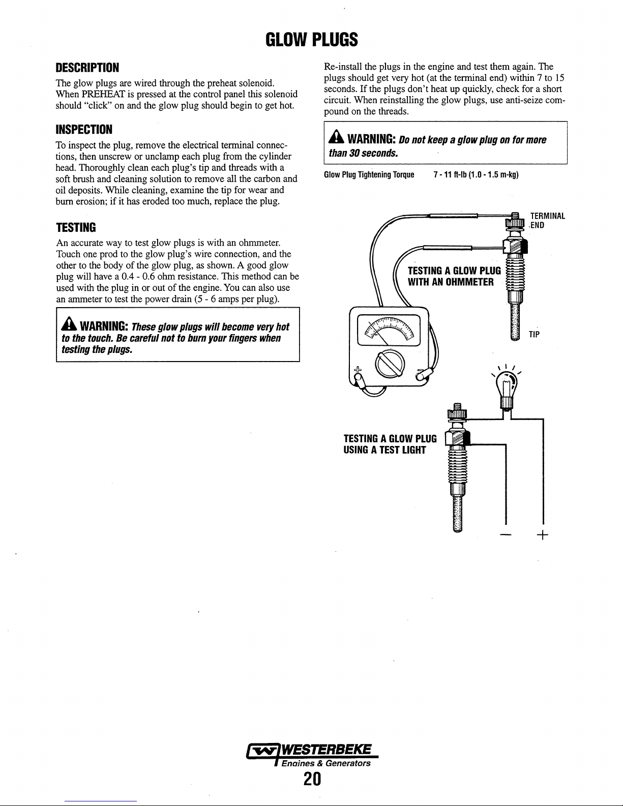
GLOW
PLUGS
DESCRIPTION
The glow plugs are wired through the preheat solenoid.
When PREHEAT is pressed at the control panel this solenoid
should
"click" on and the glow plug should begin to get hot.
INSPECTION
To inspect the plug, remove the electrical terminal connections, then unscrew or unclamp each plug from the cylinder
head. Thoroughly clean each plug's tip and threads with a
soft brush and cleaning solution to remove all the carbon and
oil deposits. While cleaning, examine the tip for wear and
bum erosion;
if
it has eroded too much, replace the plug.
TESTING
An accurate way to test glow plugs is with an ohmmeter.
Touch one prod to the glow plug's wire connection, and the
other
t~
the body
plug
wIll have a 0.4 - 0.6
used with the plug in
an ammeter to test the power drain
A
WARNING:
to
the
touch.
testing
the
of
the glow plug, as shown. A good glow
ohm
resistance. This method can be
or
out
of
the engine. You can also use
(5
- 6 amps per plug).
These
glow
plugs
will
become
Be
careful
not
to
burn
your
plugs.
fingers
very
when
hot
Re-install the plugs in the engine and test them again. The
plugs should get very hot (at the terminal end) within 7 to
seconds.
circuit. When reinstalling the glow plugs, use anti-seize compound on the threads.
A
than
Glow
If
the plugs
WARNING:
30
seconds.
Plug
Tightening
Torque 7 -11
don't
heat up quickly, check for a short
Do
not
keep a glow
H-Ib
TESTING A GLOW
WITH
AN
OHMMETER
plug
(1.0
PLUG
-1.5
on
for
m-kg)
15
more
TERMINAL
,END
TIP
TESTING A GLOW
USING A TEST
LIGHT
PLUG
+
'~IWESTERBEKE
I Enaines & Generators
20
Page 27

ENGINE
LUBRICATING
OIL
SWITCH
ENG'INE
1.
BMM
11/16
INCH
SOCKET
LUBRICATION
OIL
OIL
PRESSURE
OIL
DIAGRAM
PRESSURE
-_:lHI
OIL
CHANGE
Draining the Oil Sump. Discharge the used oil through
the sump drain hose (attached to the front
while the engine is warm. Drain the used oil completely,
replace the hose in its bracket, and replace the end cap
securely.
NOTE:
Thread
size for
is
114NPT.
Always observe the used oil as
yellow/gray emulsion indicates the presence
the oil. Although this condition is rare,
prompt attention to prevent serious damage. Call a qualified mechanic should water be present in the oil. Raw
water present in the oil can
exhaust system attached to the engine and/or a siphoning
of
raw water through the raw water cooling circuit into
the exhaust, filling the engine. This problem is often
caused by the absence
location or lack
the
lube
oil drain hose capped end
~Oll
of
of
maintenance.
ORAl.
it
is removed. A
be
the result
an anti-siphon valve, its poor
of
the engine)
HOSE
of
it
does require
of
a fault in the
water in
2.
Replacing the
ter, you may find it helpful and cleaner to punch a hole in
the upper and lower portion
oil from it into a container before removing it. This helps
to lessen spillage. A small automotive filter wrench
should be helpful in removing the old oil filter.
NOTE:
Do
filter
to
Place some paper towels and a plastic bag around the filter when unscrewing it to catch any oil left in the filter.
(Oil or any other fluid
cooling ability. Keep your engine clean.) Inspect the old
oil filter as
sealing gasket comes off with the old oil filter.
ber sealing gasket remains sealed against the filter
bracket, gently remove it.
SEALING
APPLY
CLEAN
WHEN
INSTALLING
When installing the new oil filter element, wipe the filter
gasket's sealing surface on the bracket free
apply a thin coat
on the new oil filter.
filter nipple on the oil filter bracket, and then tighten the
filter firmly by hand.
NOTE:
Generic filters
ial
standards or diameters
parts might
Immediately after
engine
there
are
3.
Filling the Oil Sump. Add new oil through the oil filler
cap on the top
After refilling, run the engine for a few moments while
checking the oil pressure. Make sure there is no leakage
around the new oil filter or from the oil drain system, and
stop the engine. Then check the quantity
lube oil dipstick. Fill to,
the dipstick, should the engine require additional oil.
Oil
Filter.
When removing the used oil fil-
of
the old filter to drain the
not punch this hole without first
make certain it
it
is removed to make sure that the rubber
GASKET
ENGINE
be
entirely different from genuine
to
make
no
oil leaks around the new oil
of
can
be
removed.
on
the engine reduces the engine's
/
OIL
SPIN
ON
TURN
ON
HAND
TIGHT
of
clean engine oil to the rubber gasket
Screw the filter onto the threaded oil
are
not
recommended.
of
important items
an
oil filter change and oil
sure
the
oil pressure
the engine
but
or
not over the high mark on
is
normal and that
through the side oil fill.
loosening
If
of
oil and
as
the
on
parts.
fill.
filter.
of
oil with the
the
this rub-
mater-
generic
run
the
Engines & Generators
21
Page 28

OIL
PRESSURE
The engine's oil pressure, during operation, is indicated
by the oil pressure gauge
normal operation, the oil pressure will range between
60 psi (2.8 and 4.2 kglcm
NOTE:
reading
an
readings
engine
OIL
PRESSURE
A newly
oil pressure
and
up
to
60
will
vary
the
SWITCH"
started,
psi (4.2 kglcnf). A warmed engine
reading
rpms.
on
2
).
cold engine
as
low
depending
/
the instrument panel. During
can
have
an
as 35 psi (2.5 kglcm
upon
the
temperature
OIL
oil pressure
can
2
).
of
OIL
LINE
PRESSURE
TESTING
The lubricating system is a pressure feeding system using
an oil pump. The engine oil is drawn from the oil sump by
40
and
have
These
the
the oil pump, which drives the oil, under pressure, through
the oil filter, oil cooler and various lubricating points in the
engine. The oil then returns to the oil sump to repeat the
continuous cycle. When the oil pressure exceeds the
fied pressure, the oil pushes open the relief valve in the oil
pump and returns to the oil sump, keeping the oil pressure
within its specified range.
To
test the oil pressure, remove the oil pressure sender, then
install a mechanical oil pressure gauge in it's place. After
warming up the engine, set the engine speed at
and read the oil pressure gauge.
Oil
Pressure
Sender
LOW
The specified safe minimum oil pressure is 4.3 + 1.4 psi (0.3
+ 0.1 kglcm
a worn bearings. For additional information on low oil
sure readings, see the ENGINE
OIL
PRESSURE
35.0
Ib/ill'
and
Switch
Torgue
OIL
PRESSURE
2
).
A gradual loss
(3.8
kg/em')
or
more
at
3000
9 -13
ft-Ib
(1.2
-1.8 m -
of
oil pressure usually indicates
TROUBLESHOOTING
speci-
3000 rpm
rpm.
kg).
pres-
chart.
OIL
PRESSURE
An oil pressure relief valve is located
just
below the injection pump. This valve opens at
appoximately
LOCATED
UNDER
FUEL
INJECTION
PUMP
ON
ENGINE
RELIEF
50
psi [343 kpa] and maintains that pressure.
JUST
THE
THE
BLOCK.
VALVE
on
OIL
PRESSURE
AS
AN
WITH
GAUGE.
WITH
THE
INSTRUMENT
the engine block
SENDOR
ACCESSORY
..
STANDARD
ADMIRAL
PANEL.
.
TESTING
OIL
PRESSURE
+
t-
OIL
PRESSURE
I~IWESTERBEKE
, Enaines & Generators
22
Page 29

REMOTE
OIL
INSTALLATION
This popular accessory is used to relocate the engine's oil fil-
ter from the engine to a more convenient location such as an
engine room bulkhead.
NOTE:
Refer to ENGINE OIL CHANGE
instructions on removing the oil filter.
APPLY A THIN
INSTALLING
TIGHTEN
CONTACTS
COAT
THIS
KIT.
AN
ADDITIONAL
THE
BASE.
OF
CLEAN
THREAD
3/4
OIL
THE
TURN
TO
THE
KIT
ON,
AFTER
O-RING
THEN
THE
NOTE
ON
REMOVED
,
WILL
in
WHEN
HAND
O-RING
THE
"IN"
THE
ADAPTER
FOR
BE
RECONNECTED
this
manualfor
AND
"OUT"
MARKINGS
WHEN
THE
INSTALLATION
HOSES
SO
CORRECTLY.
ARE
THEY
FILTER
{OPTIONAL}
To
install, simply remove the engine oil filter and thread on
WESTERBEKE's remote oil filter kit as shown. Always
install this kit with the oil filter facing down as illustrated.
Contact your WESTERBEKE dealer for more information.
NOTE:
incorrect installation
Westerbeke is
not
responsible
of
the Remote Oil Filter.
for
FASTEN
(SCREWS
engine failure due to
SECURELY
TO A BULKHEAD
ARE
OWNER
SUPPLIED)
A
CAUTION:
rectly.
If
the
pass
valve
from
reaching
failure.
immediately
If
oil
in
the
the
there
and
It
is
flows
filter
engine
is
no
check
vital
to
install
in
the
reverse
assembly
causing
oil
pressure
the
hose
the
will
an
reading~
connections.
oil
lines
cor-
direction~
prevent
Intemal
the
by-
the
oil
engine
shutdown
Engines & Generators
23
APPLY A THIN·
TER
GASKET
FILTER
CDNTACTS
ADDITIONAL
COAT
WHEN
3/4
TURN.
DF
CLEAN
INSTALLING.
THE
BASE,
OIL
TO
THE
AFTER
TIGHTEN
THE
IT
FIL-
AN
Page 30
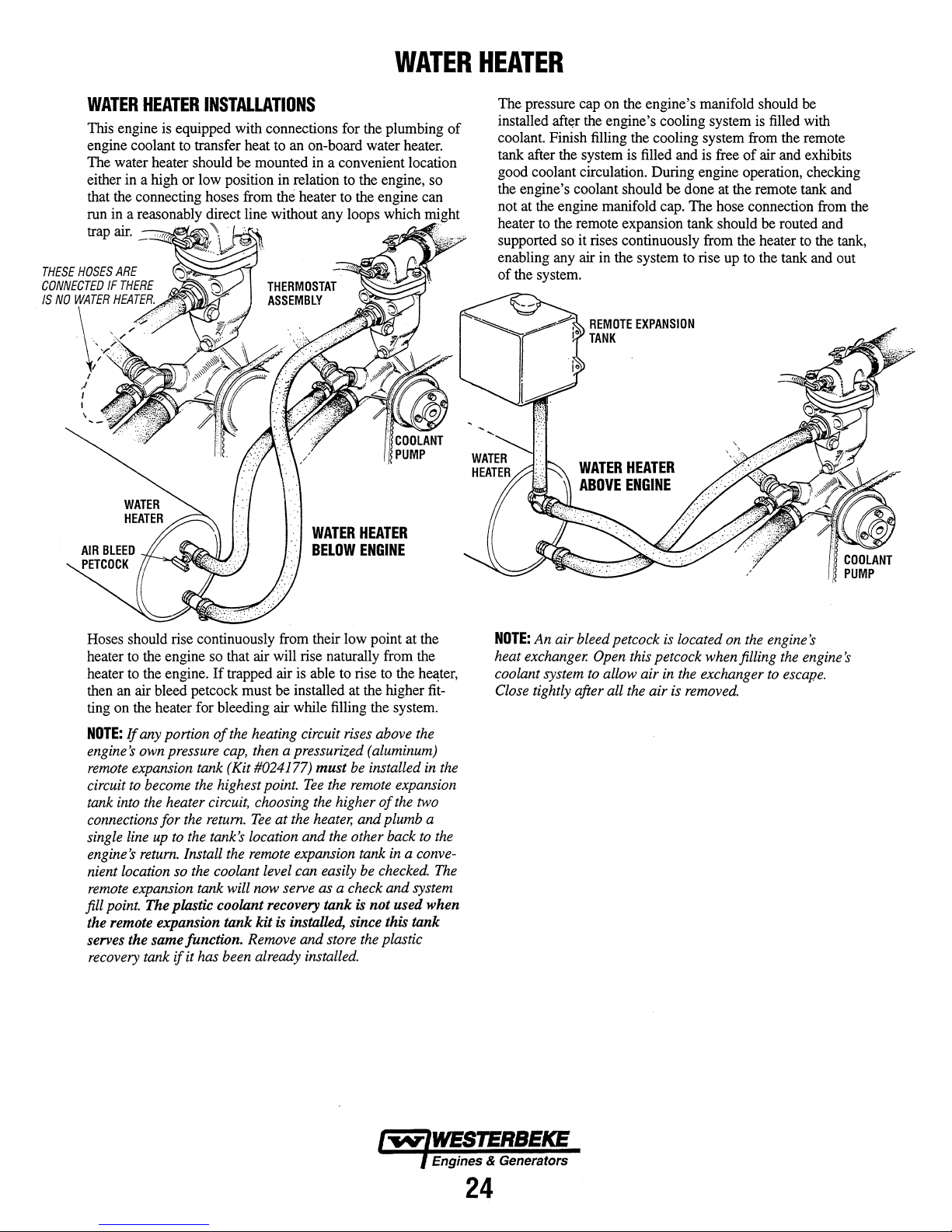
WATER
HEATER
WATER
This engine is equipped with connections for the plumbing
engine coolant to transfer heat to an on-board water heater.
The water heater should
either in a high or low position in relation to the engine, so
that the connecting hoses from
run in a reasonably direct line without any loops which might
trap air.
THESE
HOSES
CONNECTED
IS
NO
WATER
HEATER
-==~~~"
ARE
IF
THERE
HEATER.
INSTALLATIONS
be
mounted in a convenient location
the heater to the engine can
\~
I
.J
,
I
WATER
BELOW
HEATER
ENGINE
of
The pressure cap on the engine's manifold should
installed
coolant. Finish filling the cooling system from the remote
tank after the system is filled and is free
good coolant circulation. During engine operation, checking
the engine's coolant should
not at the engine manifold cap.
heater to the remote expansion tank should
supported so it rises continuously from the heater to the tank,
enabling any air in the system to rise up to the tank and out
of
aft~r
the system.
the engine's cooling system is filled with
of
be
done at the remote tank and
The
hose connection from the
be
air and exhibits
be
routed and
Hoses should rise continuously from their low point
heater to the engine so that air will rise naturally from the
heater to the engine.
then an air bleed petcock must
ting on the heater for bleeding air while filling the system.
NOTE:
If
any portion
engine's
remote
circuit
tank
own
expansion tank (Kit #024177) must
to
become
into
the
connections for
single
line
up
engine's
return.
nient location
remote
expansion tank will
point.
fill
The plastic coolant recovery tank
the remote expansion tank kit
If
trapped air is able to rise to the
of
the
pressure
heater
to
so
cap,
the
highest point.
circuit,
the
return.
the
tank's location and
Install
the
the
coolant level can easily
be
installed at the higher fit-
heating circuit
then
a pressurized
rises
be
Tee
the
remote
choosing
Tee
remote
now
the
higher
at
the
heater,
and plumb a
the
other back
expansion tank
serve as a check and system
is
is
installed, since this tank
serves the same function. Remove and store
recovery
tank
if
it has been already installed.
at
the
hel:\ter,
above
the
(aluminum)
installed
in
expansion
of
the
two
to
in a conve-
be
checked.
not used when
the
plastic
the
the
The
NOTE:
An air bleed petcock
heat
exchanger.
coolant system
Close
tightly after all
is
located
Open
this petcock when filling
to
allow air
the
air
in
the
is
on
exchanger
removed.
the
engine's
the
engine's
to
escape.
Engines &
24
Generators
Page 31
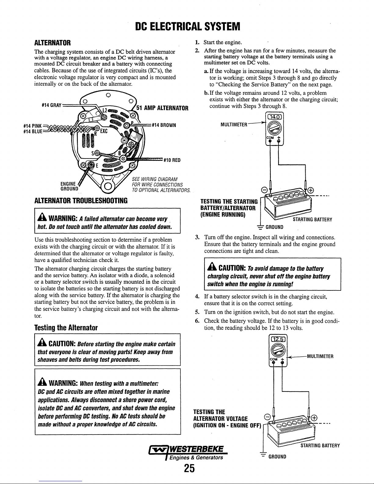
DC
ELECTRICAL
SYSTEM
ALTERNATOR
The charging system consists
with a voltage regulator, an engine
mounted DC circuit breaker and a battery with connecting
cables. Because
electronic voltage regulator
internally or on the back
#14
GRAY==~=*-
#14
PINK~~~~~~~
#14
BLUE=
ALTERNATOR
A
WARNING:
hot.
Do
Use this troubleshooting section to determine if a problem
exists with the charging circuit or with the alternator.
determined that the alternator or voltage regulator is faulty,
have a qualified technician check
The alternator charging circuit charges the starting battery
and the service battery. An isolator with a diode, a solenoid
or a battery selector switch is usually mounted in the circuit
to isolate the batteries so the starting battery
along with the service battery.
starting battery but not the service battery, the problem
the service battery's charging circuit and not with the alternator.
Testing
of
the use
TROUBLESHOOTING
A failed
not
touch
until
the
Alternator
of
a DC belt driven alternator
DC
wiring harness, a
of
integrated circuits
is
very compact and
of
the alternator.
__
SEE
FOR
TO
alternator
the
alternator
If
can
has
it.
the alternator is charging the
(Ie's),
is
WIRING
WIRE
OPTIONAL
become
cooled
is
not discharged
the
mounted
DIAGRAM
CONNECTIONS
ALTERNATORS.
very
.
down.
If
it is
is
in
1. Start the engine.
2. After the engine has run for a few minutes, measure the
starting battery voltage at the battery terminals using a
multimeter set on DC volts.
If
the voltage
a.
is
working; omit Steps 3 through 8 and go directly
tor
to "Checking the Service Battery" on the next page.
If
the voltage remains around
b.
exists with either the alternator or the charging circuit;
continue with
is
increasing toward
Steps 3 through
14
volts, the alterna-
12
volts, a problem
8.
mID
MULTIMETER
G
COM
TESTING
BATTERY/ALTERNATOR
(ENGINE
3. Tum off the engine. Inspect all wiring and connections.
Ensure that the battery terminals and the engine ground
connections are tight and clean.
4.
If
ensure that it
S.
Tum on the ignition switch, but do not start the engine.
6.
Check the battery voltage.
tion, the reading should be 12 to
THE
STARTING
RUNNING)
-=
A
CAUTION:
charging
switch
when
a battery selector switch
To
avoid
circuit,
never
the
engine
is
on the correct setting.
GROUND
damage
shut
is
is
If
to
the
off
the
engine
running!
in the charging circuit,
the battery
13
is
volts.
battery
battery
in
good condi-
A
CAUTION:
that
everyone
sheaves
A
DC
applications.
isolate
before
made
and
WARNING:
~nd
AC
DC
performing
without a proper
Before
is
clear
belts
circuits
Always
and
AC
starting
of
moving
during
test
procedures.
When
are
testing
often
with a multimeter:
mixed
disconnect a shore
converters,
DC
testing.
and
No
knowledge
the
engine
parts!
together
shut
AC
of
Keep
down
tests
AC
circuits.
make
away
in
power
the
should
certain
from
marine
cord,
engine
be
Engines & Generators
25
TESTING
ALTERNATOR
(IGNITION
THE
VOLTAGE·
ON -ENGINE
OFF)
~
0~--MULTIMETER
COM
-=
GROUND
Page 32

7.
Now
check
minal
(B+)
the
alternator
tor
is
in
the
neither
of
the
between
connections -look
the
the
voltage
and
ground.
will
be
circuit
above
alternator
between
If
the
the
same
the
alternator
is
true, a problem
and
the
for
an
opening
the
circuit
as
the
voltage
battery.
DC
alternator
is
good,
battery,
will
exists
Check
in
the
charging
ELECTRICAL
output
ter-
the
voltage
at
or
if
an
isola-
be
zero.
If
in
the
circuit
all
the
circuit.
SYSTEM
Checking
Check
have
a voltage
running.
charging circuit. Troubleshoot
circuit
isolator,
the
voltage of
If
not,
by
checking
battery
the
between
there
switch,
Service
the
service
13
is
a problem
the
wiring
and
Battery
battery.
and
14
volts
in
the
service
and
connections,
the
battery
the
This
when
service
battery
itself.
battery
the
engine
battery
charging
the
should
is
solenoid,
TESTING
BATTERY
(ENGINE
8.
Start
the
alternator output
The
voltage
should
is
over-
service
NOTE:
Before
voltmeter
the
EXC terminal if
at
tery
voltage at
If
12
volts
wiring
THE
STARTING
IALTERNATOR
RUNNING)
engine
again.
Check
the
voltage between
and
ground.
reading
be
between
or
under-charging,
facility.
to
ensure
is
and lookfor breaks and poor
for
a properly operating alternator
13.5
and
removing
the
not present at
the
that 12 volts
the
B output
14.5
volts.
have
it repaired
alternator for
DC
previous test showed only
terminal.
the
EXC
....
at
a reliable
trace
ENGINE
GROUND
the
use
a
bat-
the
-c==-
If
your alternator
repair,
excitation is present
terminal,
connections.
MUlTIMETE".
GROUND
A
CAUTION:
do
not
use a high
performing
G
COM
To
tests
on
avoid
voltage
the
altemator
,SERVICE
TESTING
BATTERY
damaging
tester
(i.e. a megger)
charging
THE
the
altemator
BATTERY
SERVICE
(ENGINE
RUNNING)
diodes,
when
circuit.
12
VOLT
DC
The
engine
has a 12
shown
on
the
diagrams
electrical
A
circuit,
.
the
however,
engine's
when
system.
CAUTION:
never
engine
to
electrical circuit.
BATTERY
The
minimum
the
engine's
Cranking
Amps
CONTROL
wiring
troubleshooting or
To
shut
is
running.
avoid
recommended capacity of
12
volt
(CCA).
CIRCUIT
volt
DC
electrical control circuit that
diagrams that
avoid
damage
off
the
engine
Shut
off
electrical
DC
shorts
control circuit
follow.
when
the
servicing
to
the
battery
engine
when
the
is
600 -900
Refer
to
battery
switch
battery
working
battery
is
these
the
DC
charging
while
Switch,
on
the
used
in
Cold
Engines & Generators
26
Battery
Review
establish a systematic maintenance schedule
engine's starting batteries
o Monitor
o Check
o
o
o
Care
the
manufacturer's recommendations
and
house batteries.
your
voltmeter
engine operation. '
the
electrolyte
hydrometer.
Use
only
distilled water
level.
Make
certain that
tight
to
the
battery
Keep
your
batteries
A
WARNING:
caUSII
severe
protective
Sulfuric
burns
gear.
for
level
to
battery
cable connections
posts
(and
clean
and
acid
on
skin
proper
and
bring
to
free
In
and
charging
specific
electrolytes
your
of
lead
damage
engine).
corrosion.
batteries
and
then
for
your
during
gravity
with
to a proper
are
can
clothing.
clean
Wear
a
and
Page 33

MARINE
ENGINE
SEE
NOTE:
An
should
be
circuit
to
disconnect
starter
from
an
emergency
leaving
the
volt
engine
typically
draw
amps
when
switch
with a continuous
rating
of
175
VDC
will
normally
this
function,
must
never
"make"
the
I I
NOTE
'~'
I
I
...I
on-off
switch
installed
in
the
battery
and
when
boat.
Twelve
starters
200
to
cranking.
amps
at
serve
but a switch
be
used
to
starter
circuit.
this
the
300
A
12
in
WIRING
DIAGRAM
$I
#39144
=
~
~
: ::r----------------...I
; ; ;
...
. . -
P2~'
- .
p
+
C
ALARM
BUZZER
ADMIRAL
PANEL
LIFT
PUMPS
"0
AED
PI
o
>
r--
ALT •
....
CAPTAIN
PANEL
"l
T""""""'"
GP
•
....
11&
elK
',e
BL.K
.,.
l
~~~~~~~~~~~~~~!·'!·1·!L'~~~~~~~~~~~~~~:;~
slIe
Engines & Generators
______
27
-----,l
~
Revised December 2002
Page 34

MARINE
ENGINE
WIRING
~
12
VDC
~------~~r71------~Mr-------------.
START
SOL.
r--,
SURfER
SCHEMATIC
r_--~~r_----------------------~
LIFT
PUMP
FUEL
'lfH[N
'B-IJ.!.C~
s,,(
TMETER
_
GNO
GNI)
BAT
IG'
KEY
sw.
r-+-+_+-
o
ALARM
____
,--+--+
--*"S~
O.P.
SENDER
TACHOMETER
___
VOL
+
+
------1
ADMIRAL
PANEL
NOTE:
WIRE
FOR
TO
BE
UPGRADED
#39144
NOTES:
THIS
PRODUCT
STARTER ExCESSIVE
SHUT
DCWN.
ENGINE
I
2.
AN
QN'OFF SWITCH
DISCONNECT
'WITH
A CONTINUOUS RATING
SWITCH
THE
PINK
4
THE
GRAY
6ATTERY ATTATCHMENT
TO
AN 8 GAUGE
IS
PRQTI:.CTED
BY A MANUAL
CURRENT
THE
BUILDER/OWNER
ARE
INSTALLED
TO
PREVENT
SHOULD
BE
BATTERY
IN
AN
AT
PLUG 2 IS
AT
PLUG
RED
NEED
10
BE
•
GAUGE
OF
USED
2 IS
#1
#14
'--=;-0;;;;---'
TO
NOT
PRESTOLITE\LEECE-NEVILLE
SHOULD
WIRE
WIRE
THE
WILL
FROM
SATTUY
U
WilL
MUST
CONTACT
INSTALLED
EMERGENCY
175
AMPS,
MAKE
UNUSED
UNUSED
MITSU81SHI
GRA
CAUSE
BE
OR
AND
AND
RESET
THE
SURE
BETWEEN
BETWEEN
AND
AT
BREAK
SHOULD
SHOULD
",OUltO
AC
.14
CIRCUIT
BREAKER LOCATED
BREAKER
TO
TRIP
INSTRUMENT PANEL.
BATTERY
AND
THE
Will
SERVE
AMP
ALT
ALT.
AND
DEVICES
STARTER
BOAT. A SWITCH
THIS FUNCTION.
CAPTAIN
THAT
THE
ELECTRICAL
THE
WHEN
LEAVING
12
voe
THE
CIRCUIT
BE
INSULATED.
I3E
INSULATED, ADMIRAL PANEL ONLY,
50
90
AMP.
TA,
eRtl
THE
ENGINE
AND
PANEL ONLY,
NEAR
WIRING,
TO
THE
Will
SEAWATER.
THI$
AND
O.P.
GAUGE
GNO
PRESTOllTE
#
14
CAPTAIN
PANEL
LAMP
TEST
sw.
+
51
AMP
STANDARD
638 I:!l.
1088
ALTERNATOR
ALTERNATOR
63C
I:!l.
D. & 108C·D.
liB
ON.
THE
I:!l. 828
:or.
---\T"CH)~
"~~r-'-'R""r=~;:::==========;1
8RN
#
14
GRA
#14
PINK
#14
LT.
BL
UNIVERSAL
PRESTOLlTE
ALE
CONNECTOR
ON
THIS SIDE
72
AMP
PROPULSION
51
AMP
ALL
RED
ALI
"v'''-L~~H_.M..~e_
Engines & Generators
28
OPT I ONAl
135A. 160A,
liOA.
0:
63C
n:
ALTERNATORS
LESTEK
ALTERNATORS
718
II
IlZ8J;b
198ft
XI
®
!..
10llC '.i:I
0HL,V
__
Revised December 2002
Page 35

MARINE
ENGINE
+
12
u
VDC
0::
LIJ
~
<C
r
"
LIJ
Q...0::1(
~IDI
<C
I I
1-'
0-
-
:::>
U
0::
u
WIRING
--,
I
I
-
SCHEMATIC
[CATALINA
STARTER
SOLENOID
r--
I I
I
I I
I I
I
L
PREHEAT
SOLENOID
r
I
II
SI
I I
YACHTS]
-,
I I I
~
___
---,
III
I
I
J
I
I
I
I
#200360
OUTPUT
r--------Jv·
STARTER
M
GLOWPLUGS
ALTERNATOR
q,
<+-
10...'<11:
r:>
'<11:"
-
TO
THE
'B'
TERM.
OF
KETSWITCH
TO
THE
START
SWITCH
en
en
wu
0::
Q...-
...J
o
TO
THE'S'
TERM.
OF
KETSWITCH
:c
I-
~--,
3:
en
TO
TERM.
KEYSWITCH
THE
'I'
TO
THE
't'
TO
THE
OF
TERM.
THE
ALARM
BUZZER BUZZER
OF
TERM.
THE
'P'
OF
ALARM
1-.¥'IWESTERBEKE
• Enqines & Generators
TO
TERM.
THE
THE'S'
OF
TACH
TO
TERM.
W.
T.
THE'S'
OF
GUAGE
LIFT
WATER
WATER
TO
THE
TERM.
THE
ALARM
BUZZER
P
SENDER
0..
\CJ
SWITCH
'c'
OF
PUMP
1--------
TEMP.
TEMP.
'"
TO
THE
GROUND
TACH
_'--
29
Page 36
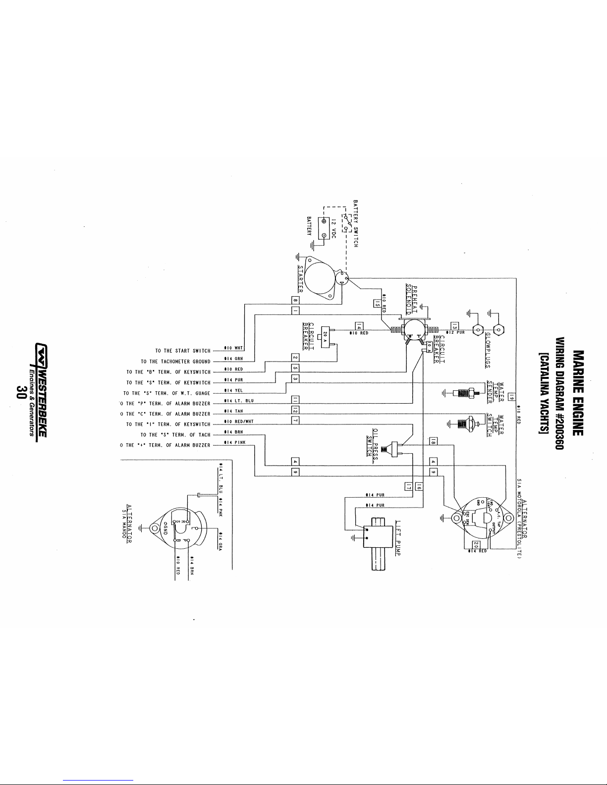
TO
THE
START
SWITCH
TO
THE
TACHOMETER
GROUND
~i
TO
THE
'B'
TERM.
OF
KEYSWITCH
CA)~;
TO
THE'S'
TERM.
OF
KEYSWITCH
=:
TO
THE
'5'
TERM.
OF
W.T.
GUAGE
fill
-0
THE
"P'
TERM.
OF
ALARM
BUZZER
o
THE
'C'
TERM.
OF
ALARM
BUZZER
iiJl'n
Q~
TO
THE
'I'
TERM.
OF
KEYSWITCH
iii
TO
THE'S'
TERM.
OF
TACH
o
THE
'.'
TERM.
OF
ALARM
BUZZER
il
'I
0-1
0
..
Ii
0
:0
,.,
'"
110
WHT
I
114
GRH
110
RED
114
PUR
114
VEL
114
L T.
BLU
114
TAN
110
RED/WHT
114
BRH
114
PINK
..
...
r----
~
~~I
I~I.,~
;;l
;;;
I
I~
"" <
10
-<
I a I-I..J
~
n I -
II
I
;::
I
:I:
I
I
I
!
:e
:~~
~
-
.....
:II
:s:
n
-
Z
;!:i
G:t
:a:-
:Pi
11:1
:a
...
-
-
I~E
-
:e-
Z
z
G:t
m
:e-
:II
:=
:e-
m
..
a:
z
~~E
0
n
m
:0
::z:
~
,.,
-
'"
-t
~~
=
Z
en
......
=
m
eo,)
en
=
01
-
»
II!
I
t
Page 37

The
following
relating
lems,
and
troubleshooting
to
engine
service,
the
recommendations
the
table
describes
probable
to
overcome
ENGINE
certain
problems
causes
of
these
these
problems.
TROUBLESHOOTING
NOTE:
The
engine s electrical system
prob-
ampere
the
back
the
same
manual reset circuit breaker located
of
the
engine.
The
preheat solenoid
bracket.
is
protected
by a 20
on
a bracket at
is
mounted
on
No
panel
indications;
or
fuel
pump
and
PREHEAT
button
button
OK;
solenoid
cranks,
fuel
solenoid
can't
runs
not
charging
is
not
be
down.
is
on
START
engagement.
START
indications
fuel
Engine
start,
Engine
Battery
Battery
Problem
fuel
not
working
button
is
depressed,
is
depressed;
starter
solenoid
functioning.
but
does
energized.
stopped.
solenoid
(key
is
depressed).
no
starter
panel
OK;
not
switch
Battery
1.
20-amp
2.
10-amp
3.
preheat
4.
Loose
5.
Preheat
1.
Connection
2.
Gear
3.
Faulty
Faulty
4.
5.
Loose
Low
6.
1.
Poor
Defective
2.
Faulty
1.
Preheat
2.
Low
3.
Faulty
1.
Disconnect
2.
Fuel
3.
1.
Oil
pressu
High
2.
Low
3.
Poor
4.
DC
altemator
5.
(tachometer
DC
charge
1.
Alternator
2.
Probable
switch
not
circuit
breaker
breaker
tripped
solenoid
battery
connections.
solenoid
to
solenoid
shift
not
in
switch.
solenoid.
battery
connections.
battery.
connections
fuel
solenoid.
fueling
system.
solenoid
battery
power.
DC
altemator.
fuel
shut-off
run
solenoid
re
switch.
resistance
resistance
battery
leak
leak.
connections.
not
not
circuit
drive.
Cause
on.
tripped.
on
not
operating.
faulty.
neutral.
to
fuel
solenoid.
faulty.
cable.
will
not
de-energize.
to
ground.
charging
operating).
faulty.
1.
Check
2.
Reset
circuit
3.
Check
preheat
4.
Check
engine
5.
Check
1.
Check
2.
Gear
HURTH
3.
Check
4.
Check
5.
Check
Check
6.
1.
Check
2.
Check
fuel
1.
Check
1
a.
Check
1b.
Fuel
fuel
2.
Check
3.
Switch
3a.
Replace
1.
Remove
2.
Check
off
3.
Manually
solenoid
1.
Observe
is
2.
Check
lines.
after
3.
Check
4.
Check
corrosion
5.
Check
DC
1.
Perform
Testing
2.
Check
for
volts
Verification}Remedy
switch
and/or
breaker,
if
and
check
the
voltage
solenoid.
(+)
connection
ground
stud.
solenoid
connection.
shift
must
HSW
TRANSMISSIONS).
switch
with
that
12
volts
battery
connections.
battery
charge
connections.
that
12
run
filters
system.
the
not
ELECTRICAL
loose
volts
solenoid.
that
fuel
for
air
in
clogged.
solenoid.
to
combine
batteries.
Exc.
connection
connection
fuel.
disconnect
at
the
injection
if
gauges
running.
Test
wiring.
Insert
(Do
not
start
short
is
located.
all
wires
cable
connections
connections,
DC
voltage
the
Battery
drive
belt
connections.
are
present
battery
connections.
breaker
trips
again,
circuit
for
both
at
and
to
starter
Check
"S"
terminal
be
in
neutral
ohmmeter.
are
present
state.
are
present
valves
are
open.
fuel
system.
Replace
house
and
at
at
shut-off
the
12
pump.
and
panel
the
oil
pressure
sensitive
engine.)
for
temperature
at
check
belt
SYSTEM/ALTERNATOR.
check
Charging
tension;
alternator
Check
at
the
Exc.
shorts
to
after
the
solenoid
battery
cable
for
voltage.
(see
NEUTRAL
at
the
at
the
Bleed
air
filters
and
start
batteries.
alternator;
lever.
Pull
volt
connection
lights
are
(0 -.25
Remove
rise
battery
for
tension,
of
generator
Circuit.
should
output
terminal.
check
ground.
breaker
and
connections.
solenoid
(+)
connection
from
bleed
repair
lever
activated
switch.
amp)
connections
to
locate
loose
test
charging
with
voltmeter.
preheat
solenoid
on
the
(-)
connection
SWITCH
connection.
on
fuel
system.
air
from
alternator.
back
to
close
to
the
fuel
when
meter
in
battery
and
the
fault.
connections,
alternator.
circuit.
turn
freely.
Ensure
to
under
the
run
engine
replace
See
See
Check
12
(continued)
~
Engines & Generators
31
Page 38

ENGINE
TROUBLESHOOTING
Engine
slows
Engine
overheats/shuts
Engine
alarm
Engine
alarm
Exhaust
smoke
Problem
and
stops.
sound
pulsates.
sounds
continuously.
problems
down.
Fuel
1.
2.
Switches
or
disconnected.
3.
Fuel
20
Amp
4.
Exhaust
5.
6.
Water
7.
Air
Raw
1.
2.
Coolant
1.
Loss
2.
Oil
Engine
1.
High
2.
too
Blue
1.
White
2.
3.
Black
Probable
lift
pump
and/or
starvation.
circuit
system
in
fuel.
intake
obstruction.
water
not
not
circulating.
of
oil.
pressure
switch.
coolant.
temperature
Iowa
temperature.
smoke.
smoke.
smoke.
Cause
failure.
wiring
loose
breaker
tripping.
is
restricted.
circulating.
switch
opens
at
VerificationJRemedy
1.
Fuel
lift
pump
should
pump
with
spare.
2.
Inspect
wiring
Inspect
switches
Check
fuel
3.
4.
Check
Ensure
cause
5.
Check
exhaust
Pump
6.
bleed
7.
Check
1.
Raw
2.
Obstruction
2a.
Thermostat -remove
Replace
2b.
Loss
for
2c.
Broken
2d.
Air
bleed
1.
Check
oil
2.
Replace
Check
1.
2.
.
Check
check
Incorrect
1.
1a.
Crankcase
through
2.
Engine
2a.
Faulty
3.
Improper
3a.
Fuel
insufficient
exhaust
3b.
Improperly
3c.
Lack
ventilation.
3d.
Overload.
supply,
for
high
breaker
tripping.
for
blockage,
elbow.
water
fuel
system.
air
intake
water
pump
thermostat.
of
coolant -check
leaks.
or
loose
leak
in
system;
air.
Add
dipstick,
drain
hose
oil
pressure
engine
for
satisfactory
with
ohmmeter,
grade
is
the
is
running
injector
grade
burn
incomplete
air
system;
timed
of
air -check
make a distinct
for
short
circuits
for
proper
fuel
valves,
DC
amperage
is
not
overly
collapsed
from
fuel
tank(s);
filter
cartridge.
failure.
Check
at
raw
water
intake
and
hoses,
belts -tighten/replace.
run
engine
coolant
as
needed.
look
for
oil
switch.
level.
operation
replace
engine
with
cold.
incorrect
fuel.
due
proper
air
injectors
air
intake
leaks
oil.
injector
to
combustion
intake).
connection.
coolant
of
overfilled
exhaust).
or
of
for
check
ticking
and
loose
operation.
fuel
draw
sensitive
hose,
change
impeller -replace.
or
test
in
and
if
engine
high
or
valves,
and
connections.
lift
pump.
during
operation.
to
heat
carbon
filters
raw
water
hot
water.
hose
clamps,
open
the
at
oil
filter
with
switch
faulty.
oil
(oil
is
timing.
back-pressure
(check
or
poor
air
filter.
sound.
Replace
which
would
buildup
at
and
filter.
drain
plug,
pressure
cap
and
at
bypassed,
blowing
out
in
exhaust
for
restrictions
compression.
Check
for
proper
etc.
to
or
in
TROUBLESHOOTING
If
the gauge reading is other than what is normally indicated
by the gauge when the instrument panel is energized, the first
step is to check for 12 volts DC between the ignition (B+)
and the Negative
Assuming that there is 12 volts as required, leave the
instrument panel energized and perform the following steps:
1.
Disconnect the sender wire at the gauge and see
gauge reads zero, which is the normal reading for this
situation.
2. Remove the wire attached to the sender terminal at the
sender and connect it to ground.
full scale, which is the normal reading for this situation.
(B-)
terminals
of
the gauge.
See
COOLANT
if
if
the gauge reads
~
TEMPERATURE
If
both
AND
of
undoubtedly
conductor from the sender to the gauge or with the sender.
If
either
probably defective and should be replaced.
Assuming the gauge is
the
sender to the sender terminal at the gauge for continuity.
Check that the engine block is connected to the ground.
Some starters have isolated ground terminals and
battery is connected to the starter (both plus and minus
terminals), the ground side will not necessarily be connected
to the block.
WESTERBEKE
Engines & Generators
32
OIL
PRESSURE
GAUGES
the above gauge tests are positive, the gauge is
OK
and the problem lies either with the
of
the above gauge tests are negative, the gauge is
OK, check the conductor from the
if
the
Page 39

TACHOMETER
TACHOMETER/HOUR
The tachometerlhour meter used in propulsion engine instrument panels contains two separate electrical circuits with a
common ground.
other the tachometer. The hour meter circuit operates on
volts alternator charging voltage supplied to the (+) terminal
on the
back'ofthe
The tachometer circuit operates on
from one
tachometer input terminal while the engine is running, and
the alternator producing battery charging voltage 13.0-14.8
volts DC.
The following are procedures to follow when troubleshooting a fault in either
meter.
Hour
Check for the proper
terminals.
1.
2. Voltage not present - trace
Tachometer
Check for the proper
terminal and (-) terminal with the engine running.
1.
2. AC voltage not present - check for proper alternator DC
3. Check for AC voltage at tach terminal
4. Check electrical connections from tachometer input ter-
Tachometer
1.
2. Check for good ground connection between meter (-) ter-
3. Check that alternator is well grounded to engine block at
of
the diodes in the alternator and supplied to the
meter
Voltage present - meter is defective - repair
nections for fault. (Jump 12 volts DC to meter
terminal to verify the operation.)
Inoperative
Inoperative
Voltage present - attempt adjusting meter through calibration access hole. No results, repair or replace meter.
output voltage.
ground.
minal to alternator connection.
Sticking
Check for proper AC voltage between "tach inp." terminal and (-) terminal.
minal and alternator.
alternator pivot bolt.
METER
One circuit operates the hour meter and the
12
instrument.
AC
voltage 6-8 volts, fed
of
the two circuits in a tachometerlhour
DC
voltage between (+) and (-)
or
replace.
(+) and (-) electrical con-
(+)
AC
voltage between tachometer input
on alternator to
NOTE:
Current
dial
to
set
calibrating screw
IDLE
SPEED
&
TACHOMETER
Checking
NOTE:
In
the
tachometer
engine ~ rpm
model tachometers
the
tachometer
is
then
to
used for fine
use a coarse
the
crankshaft pulley
tuning.
adjustment
AC
ADJUSTMENT
CHECK
the
idle
speed
a new installation having new instrument
may
not always
This
calibration should
(New
Installation)
be
correctly calibrated
be
checked
rpms.
(-)
INP
VOLTAGE
panels,
in
all
installations.
1.
Warm up the engine to normal operating temperature.
Remove any specks on the crankshaft pulley with a clean
cloth and place a piece
pulley to facilitate use
Start and idle the engine.
2.
Aim the light
3.
confirm the engine speed. Check the instrument panel
tachometer reading. Adjust the tachometer
using the instrument coarse adjustment to calibrate the
instrument reading to the closest
is showing. Then use the fine calibration adjustment to
bring the instrument to the exact reading as the photo tach.
4. Adjust the idle speed
specified value.
of
of
suitable reflecting tape on the
of
a photoelectric type tachometer.
the tachometer onto the reflecting tape to
in
the panel
R.P.M. that the photo tach
if
the engine speed is not within the
The
)
TERMINAL
TERMINAL
to
the
new
by
Tachometer
a. With a hand-held tach on the front
ley retaining nut or with a strobe-type tach, read the front
crankshaft pulley rpm at
b.
Adjust the tachometer with a small Phillips type screwdriver through the calibration access hole in the rear
the tachometer. Zero the tach and bring it to the rpm
indicated by the strobe or the hand tach. (Verify the rpm
at idle and at high speed rpm,). (Adjust the tach as
needed.)
Inaccurate
--..
idle,
of
the crankshaft pul-
of
Engines & Generators
33
Page 40
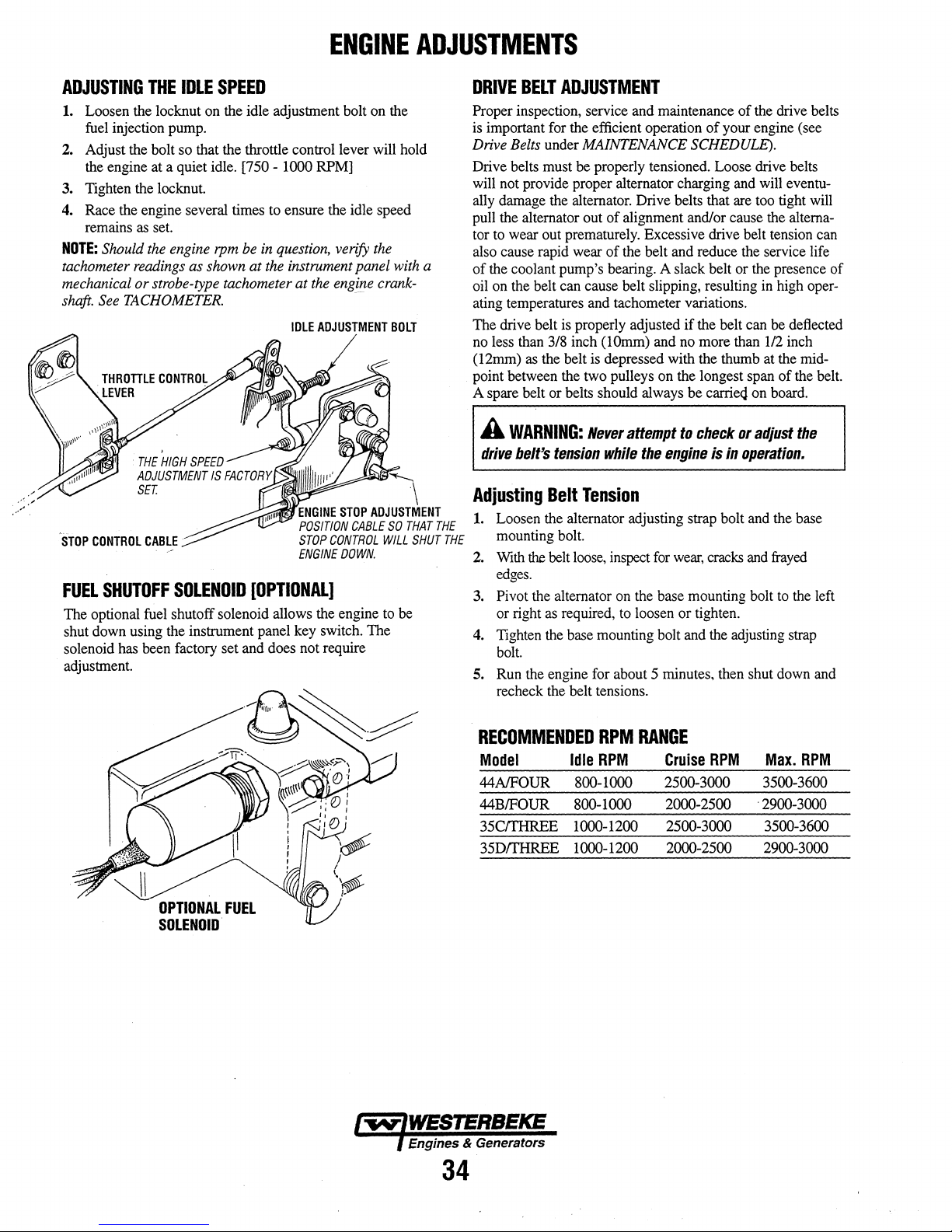
ENGINE
ADJUSTMENTS
ADJUSTING
1.
Loosen the locknut on the idle adjustment bolt on the
fuel injection pump.
2.
Adjust the bolt so that the throttle control lever will hold
the engine at a quiet idle.
3. Tighten the locknut.
4. Race the engine several times to ensure the idle speed
remains
NOTE:
tachometer
mechanical or strobe-type tachometer at
shaft.
See
THE
as
set.
Should
the
engine
readings
TACHOMETER.
IDLE
rpm
as
shown at
SPEED
[750 - 1000 RPM]
be
in
question,
the
instrument panel
IDLE
verify
the
the
engine
crank-
ADJUSTMENT
with
BOLT
----
ENGINE
STOP
POSIT/ON
STOP
CONTROL
FUEL
The optional fuel shutoff solenoid allows the engine to be
shut down using the instrument panel key switch. The
solenoid has been factory set and does not require
adjustment.
CABLE
SHUTOFF
SOLENOID
[OPTIONAL]
STOP
ENGINE
ADJUSTMENT
CABLE
CONTROL
DOWN.
SO
WILL
a
\
THAT
SHUT
DRIVE
Proper inspection, service and maintenance
is important for the efficient operation
Drive Belts under MAINTENANCE
Drive belts must be properly tensioned. Loose drive belts
will not provide proper alternator charging and will eventually damage the alternator. Drive belts that are too tight will
pull the alternator out
tor to wear out prematurely. Excessive drive belt tension can
also cause rapid wear
of
oil on the belt can cause belt slipping, resulting
ating temperatures and tachometer variations.
The drive belt is properly adjusted
no less than
(12rnrn) as the belt is depressed with the thumb at the midpoint between the two pulleys on the longest span
A spare belt or belts should always be
Adjusting
1.
THE
THE
2.
3.
4.
5. Run the engine for about 5 minutes, then shut down and
BELT
ADJUSTMENT
of
the drive belts
of
your engine (see
SCHEDULE).
of
alignment and/or cause the alterna-
of
the belt and reduce the service life
the coolant pump's bearing. A slack belt or the presence
if
the belt can be deflected
3/8
inch (IOrnm) and no more than
carrie<j
on board.
A
WARNING:
drive
belt's
Loosen the alternator adjusting strap bolt and the base
mounting bolt.
With the belt
edges.
Pivot the alternator on the base mounting bolt to the left
or right as required, to loosen or tighten.
Tighten the base mounting bolt and the adjusting strap
bolt.
recheck the belt tensions.
tension
Belt
Tension
lo()se,
Never
while
inspect for
attempt
the
engine
wear,
to
check
or
is
in
operation.
cracks and frayed
adjust
in
high oper-
112
inch
of
the belt.
of
the
OPTIONAL
FUEL
SOLENOID
RECOMMENDED
Model
44AJFOUR
44BIFOUR
35CITHREE 1000-1200 2500-3000
35DITHREE
Engines & Generators
34
RPM
RANGE
Max.
Idle
RPM
800-1000
800-1000 2000-2500
1000-1200 2000-2500 2900-3000
Cruise
RPM
2500-3000 3500-3600
RPM
. 2900-3000
3500-3600
Page 41

ENGINE
NOTE:
WESTERBEKE recommends that the following engine adjustments be
below
TESTING
Make certain the oil level (dipstick) is at the correct level and
the air intake filter is clean. The battery and starter motor
must also be in good condition.
1.
2. Move the control lever to a position for shutting off the
3. Remove all the glow plugs from the engine and install
ENGINE
Warm the engine to normal operating temperature.
fuel. (Disconnect the wires
used).
the compression gauge/adapter combination to the cylinder on which the compression is to be measured.
TESTING
COMPRESSION
if
ENGINE
peiformed by a competent engine mechanic. The information
is
provided
a fuel shutdown solenoid is
to
ADJUSTMENTS
assist the mechanic.
COMPRESSION
PRESSURE
GAUGE
FUEL
INJECTORS
In case
of
severe vibrations and detonation noise, have the
injectors checked and overhauled
injection service center.
loss
of
positive fuel pressure to the injection pump can result
in injector faults. Since fuel injectors must be serviced in a
clean room enviroment, it is best to carry at least one extra
injector as a spare should a problem occur.
Before removing the old injector, clean the area around the
base
of
the injector to help prevent any rust or debris from
falling down into the injector hole.
out easily and is held in by carbon build-up or the like, work
the injector side-to-side with the aid
free it, and then lift it out.
The injector seats in the cylinder head on a copper sealing
washer. This washer should be removed with the injector and
replaced with a new washer when the new injector is
installed.
Injector
to
Cylinder
Head
Poor fuel quality, contaminants and
Tightening
by
an authorized fuel
If
the injector will not lift
of
Torque
40
the socket wrench to
± 4
ft-lb
(5.5 ± 0.5
kgf-m)
ADAPTER
~WPLUGHDLE
4. Close the raw water seacock (thru-hull).
5. Crank the engine and allow the gauge to reach a
maximum reading, then record that reading.
6. Repeat this process for each cylinder.
Compression
Maximum
(3
kgf/cm2)
NOTE:
lfthe
repair
7. Re-install the glow plugs (use anti-seize compound on
the threads) and reset the fuel shut-off to the run position.
8.
Open the raw water seacock (thru-hull).
LOW
COMPRESSION
When low compression is found, determine the cause by
applying a small amount
plug hole. Allow the oil to settle.
Install the pressure gauge and repeat the above test.
compression reading rises dramatically, the fault is with the
rings.
If
with the valves.
A slight rise in compression would indicate a problem with
both the rings and the valves.
pressure
427
psi
(30
kgf/cm2)
permissible
readings are below the limit, the engine needs
the compression valve does not rise, the problem is
difference
between
of
oil in the cylinder
at
290
rpm.
cylinders
is
42.7
thru
psi
the glow
If
the
FUEL
INJECTOR
Engines & Generators
35
Page 42
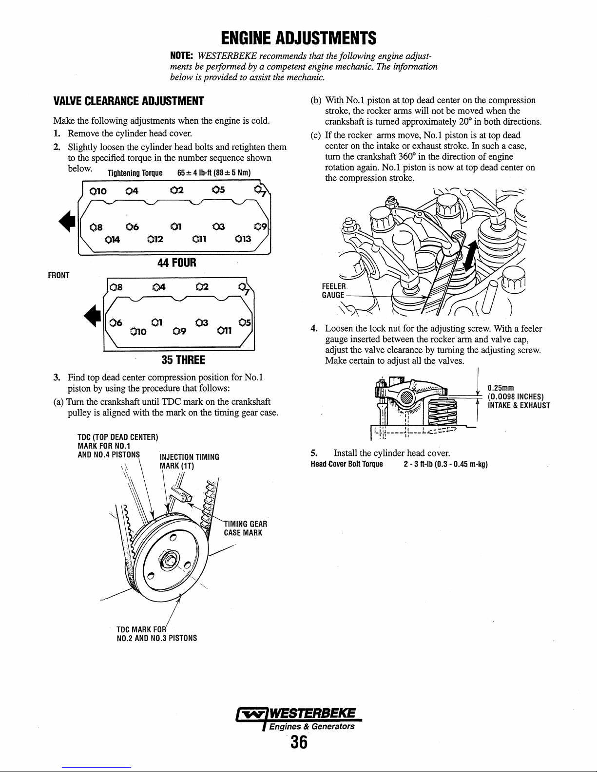
NOTE:
ments
below
be
is
ENGINE
WESTERBEKE
performed by a competent engine
provided
to
ADJUSTMENTS
recommends
assist
the
that
mechanic.
the
following engine adjust-
mechanic.
The
information
VALVE
Make the following adjustments when the engine is cold.
1. Remove the cylinder head cover.
2. Slightly loosen the cylinder head bolts and retighten them
FRONT
3. Find top dead center compression position for No.1
(a) Turn the crankshaft until
CLEARANCE
to the specified torque in the number sequence shown
below.
Tightening
•
piston by using the procedure that follows:
ADJUSTMENT
Torque
04
06
012
02
01
44
35
FOUR
65
THREE
± 4
Ib-ft
0'11
(88
os
± 5
Nm)
IDe mark on the crankshaft
pulley is aligned with the mark on the timing gear case.
(b) With No.1 piston at top dead center on the compression
stroke, the rocker arms will not be moved when the
crankshaft is turned approximately
If
the rocker arms move, No.1 piston is at top dead
(c)
center on the intake or exhaust stroke. In such a case,
turn the crankshaft 360
rotation again. No.1 piston is now at top dead center on
the compression stroke.
4. Loosen the lock nut for the adjusting screw. With a feeler
gauge inserted between the rocker arm and valve cap,
adjust the valve clearance by turning the adjusting screw.
Make certain to adjust all the valves.
0
in the direction
~~
200 in both directions.
of
engine
0.25mm
(0.0098
INCHES)
INTAKE & EXHAUST
TOC
(TOP
MARK
AND
NO.4
DEAD
FOR
PISTONS
CENTER)
NO.1
\~
\
TOC
MARK
NO.2
AND
FOR
NO.3
PISTONS
5. Install the cylinder head cover.
Head
Cover
Bolt
Torque
2 -3
ft-Ib
(0.3 -0.45
m-kg)
Engines & Generators
·36
Page 43

J.S.
AND
B.W.
DESCRIPTION
The transmission's gear ration is 2.47 to
transmission rotates opposite to the engine when in forward
gear. The transmission transmits its power with case-hardened helical gears and, in reverse, an intermediate gear. The
reversing process is carried out by a servo double disc system. For safety reasons, the transmission is
lubricating oil for shipment. Before leaving the factory, each
transmission is thoroughly tested with oil in the transmission.
This testing, among other things provides all
parts with a coating
viding reliable protection against corrosion for at least one
year
if
the transmission is properly stored.
The transmission is an immersion-lubricated type. Fill the
transmission up to
on the dipstick with
oil exclusively. Multigrade oils are not to
transmission.
may have an
of
oil. This oil acts as a preservative, pro-
or
near the top
SAE
20W/20
DO
NOT
mi~
API specification
giades
of
1.
This manual
NOT filled with
the internal
of
the machined notch cut
or
SAE 30 weight engine
be
used in this
of
oil! Lubricating oils
CF
or CG-4.
LUBRICATION
The oil capacity for the transmission is approximately 1.0
quart (1.0 liter). Check the oil level daily after the engine has
been warmed and stopped. The oil level should be main-
tained at the top
the dipstick is completely inserted into the transmission hous-
ing. Make sure the two
good shape. These
of
the machined flat on the dipstick when
O-ring gaskets on the dipstick are in
O-rings will keep the dipstick in place.
TRANSMISSIONS
If
the throw distance (or travel)
short, the gear box lever cannot fully engage the transmission
into
FORWARD
mission's internal clutches will wear prematurely and the
transmission may over heat and eventually fail.
Excessive throw distance in the remote control level is not
detrimental to the transmission. Note that the position
remote control lever should align with the
ing on its bracket when the transmission is really in
NEUTRAL.
or
REVERSE.
.
JS
GEAR
SHIFT
f.>
CABLE.
REVERSE
GEAR
/
/
d
of
the remote cable is too
In this situation, the trans-
NEUTRAL
BOX
SHIFT
LEVER
.
NEUTRAL
of
the
mark-
FORWARD
Change the transmission oil after the first 25 hours
operation and thereafter every
imum. The transmission has a 6
plug for draining the oil.
drain from the transmission, warm the oil by running the
engine in
This oil may also
dipstick opening so the oil may
oil temperature must not exceed
NEUTRAL
b~
for approximately 10 to 15 minutes.
removed by attaching a pump into the
250 hours or once a year, min-
mm
Allen Hex wrench drain
To
make sure most
be
sucked out. The operating
250°F (120°C).
of
the oil will
of
engine
CONTROLS
The only controls required to operate the transmission is a
single level remote controlled cable. The cable should be
attached to the gear box lever using the cable bracket
supplied with the unit. Both the gear box lever and the
remote control
when the cable' is
the remote cable an equal throw distance to shift the gear box
into
FORWARD
position without running out
1-112
inches
the transmission's gear box lever to each
positions.
lever must be in the
attached to the gear box lever. This allows
or into
REVERSE
of
cable throw from the
NEUTRAL
from the
of
cable. Allow approximately
NEUTRAL
NEUTRAL
of
the two drive
position
position on
SHIFTING
To
shift the transmission fron
exert a
heavy push to the remote control lever. A gentle throw
may not carry enough force to actually shift the transmission's internal gears. A gentle throw is signalled by the transmission not engaging into the desired drive. Make sure the
remote control lever is lubricated at least once each operating
season. Shift the transmission while the engine is running at
1200 rpm or below.
A
CAUTION:
gear
box
this
plate
transmission
ensure
equal
Loosening
transmission
lever
and
of
has
this
NEVER
cover
the
actuating
been
throw
cover's
warranty.
NEUTRAL
remove
from
transmission.
finely
distance
capscrews
or
loosen
level
inside
adjusted
of
internal
into FORWARD,
the
two-bolt
The
position
of
the
at
the
factory
mechanisms.
voids
the
of
to
I"""""WESTERBEKE
, Enaines & Generators
37
Revised
October
2001
Page 44

J.S.
AND
B.W.
TRANSMISSIONS
BELL
SAILING
The transmission should
while sailing. Leaving the transmission in
sailing alleviates unnecessary drag
propeller is able to freewheel (spin). However,
mission is left in its
transmission will not be damaged. (Leaving the transmission
in
OPERATION
NEUTRAL
be
left in its NEUTRAL position
NEUTRAL
on
the vessel because the
FORWARD
is just good sailing practice.)
gear while sailing, the
if
the trans-
COOLING
The transmission is raw water-cooled. Raw water enters the
transmission through a stainless steel inlet pipe located at the
base
of
the bell housing. This water helps to cool the trans-
mission's lubricating oil.
HOUSING
RAW
WATER
COOLING
J.S.
and
B.W.
TRANSMISSIONS
J.S.
AND
B.W.
General
Gear
ratio
(optional)
Propeller
(Direction
Propeller
Lubricating
Transmission
Capacity
ShaH
of
Rotation)
Oil
Sump
TRANSMISSIONS
Case-hardened
intermediate
by
servo
double
2.47
: 1
Right
hand -standard
See
propeller
SAE
20WI20
not
mix
grades
API,
CF,
CG-4,
1
qt.
(1
liter)
SPECIFICATIONS
helical
gears,
reverse
disc
recommendations.
or
SAE
of
oil
or
SJ.
with
gear.
Reversing
system.
transmission
30
exclusively
or
use
multigrades).
while
COUPLING
an
out
(Do
SERVICE
If
any seal on the transmission shows signs
the transmission looked at by a qualified WESTERBEKE
dealer. This problem, especially concerning the rear seal, is
often contributed to an improper alignment
transmission's coupling and the propeller shaft's coupling.
of
Disassembly
mended.
be done by an authorized WESTERBEKE service center.
the transmission in the field is not recom-
If
an overhaul
or
repair is needed, the work should
of
leaking, have
of
the
MAINTENANCE
Transmission maintenance is minimal. Keep the exterior
housing clean, check the fluid level as part
routine, and change the fluid every
Periodically inspect the transmission and the cooler for leaks
and corrosion. Make certain the air vent is clear and when
checking the fluid level look for signs
(fluid will appear as strawberry cream).
300 operating hours.
of
your regular
of
water contamination
Lay-up/Winterize
Storage requires special care. Follow these procedures:
NOTE:
This
operation will usually occur
water water cooling system
is
properly
when
the
winterized.
engine
raw
o Clean up the transmission and touch-up any unpainted
areas (use heat resistant paint).
~_~
Fill the transmission with
internal corrosion. (Extended.storage only, 12 months
or more).
SAE
30 engine oil to prevent
o Loosen attaching hardware from the transmission output
flange and propeller shaft coupling flange before
removing the boat from the water. Seperate the flanges
and spray with lubricant.
o Inspect the gear shift cable, linkage, and attachments.
Look for corrosion
the conduit, and bending
all moving parts.
NOTE:
If
the
transmission
(tWelve
months or
prevent internal
the
engine
back
of
more),
corrosion.
into
service.
the end fittings, cracks
of
the actuator rods. Lubricate
is
to
be
stored for a
it should
Reduce
be
topped off
the
oil level
.
long
with
before
or
time
cuts in
oil
putting
to
Engines & Generators
38
Revised
October
2001
Page 45
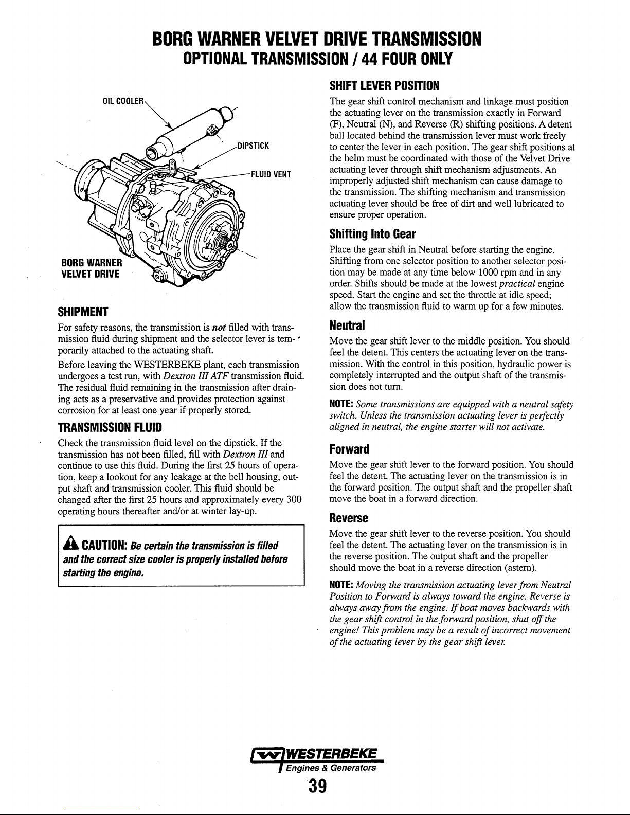
BORG
WARNER
VELVET
DRIVE
TRANSMISSION
BORG
WARNER
VELVET
DRIVE
OIL
"U~'Ll:fll'
OPTIONAL
TRANSMISSION
SHIPMENT
For safety reasons, the transmission is not filled with trans-
mission fluid during shipment and the selector lever is temporarily attached to the actuating shaft.
Before leaving the WESTERBEKE plant, each transmission
undergoes a test run, with
The residual fluid remaining in the transmission after drain-
ing acts as a preservative and provides protection against
corrosion for at least one year
TRANSMISSION
Check the transmission fluid level on the dipstick.
transmission has not been filled, fill with
continue to use this fluid. During the first 25 hours
tion, keep a lookout for any leakage at the bell housing, output shaft and transmission cooler. This fluid should be
changed after the first 25 hours and approximately every
operating hours thereafter and/or at winter lay-up.
A
CAUTION:
and
the
starting
correct
the
Be
size
engine.
Dextron III ATF transmission fluid.
if
properly stored.
FLUID
Dextron III and
certain
cooler
the
transmission
is
properly
installed
If
the
of
is filled
before
opera-
300
/44
FOUR
SHIFT
LEVER
The gear shift control mechanism and linkage must position
the actuating lever on the transmission exactly in Forward
(F), Neutral (N), and Reverse (R) shifting positions. A detent
ball located behind the transmission lever must work freely
to center the lever in each position. The gear shift positions at
the helm must be coordinated with those
actuating lever through shift mechanism adjustments. An
improperly adjusted shift mechanism can cause damage to
the transmission. The shifting mechanism and transmission
actuating lever should be free
ensure proper operation.
Shifting
Place the gear shift in Neutral before starting the engine.
Shifting from one selector position to another selector position may
order. Shifts should be made at the lowest
speed. Start the engine and set the throttle at idle speed;
allow the transmission fluid to warm up for a few minutes.
Into
be
made at any time below 1000 rpm and in any
ONLY
POSITION
Gear
of
the Velvet Drive
of
dirt and well lubricated to
practical engine
Neutral
•
Move the gear shift lever to the middle position. You should
feel the detent. This centers the actuating lever on the trans-
mission. With the control in this position, hydraulic power is
completely interrupted and the output shaft
sion does not tum.
NOTE:
Some
switch.
aligned
transmissions
Unless
the
in
neutral,
transmission actuating lever
the
are
equipped with a neutral safety
engine starter will not
of
the transmis-
is
perfectly
activate.
Forward
Move the gear shift lever to the forward position.
feel the detent. The actuating lever on the transmission is
the forward position. The output shaft and the propeller shaft
move the boat in a forward direction.
You
should
in
Reverse
Move the gear shift lever to the reverse position. You should
feel the detent. The actuating lever on the transmission is in
the reverse position.
should move the boat in a reverse direction (astern).
NOTE:
Moving
Position
always away from
the
engine!
of
to
Forward
gear shift control
This
problem may
the
actuating lever
The
output shaft and the propeller
the
transmission actuating lever from Neutral
is
always toward
the
engine.
in
the
forward position, shut off
be
by
the
If
a result
gear shift
the
engine.
boat moves backwards
of
incorrect movement
lever.
Reverse
is
with
the
Engines & Generators
39
Page 46
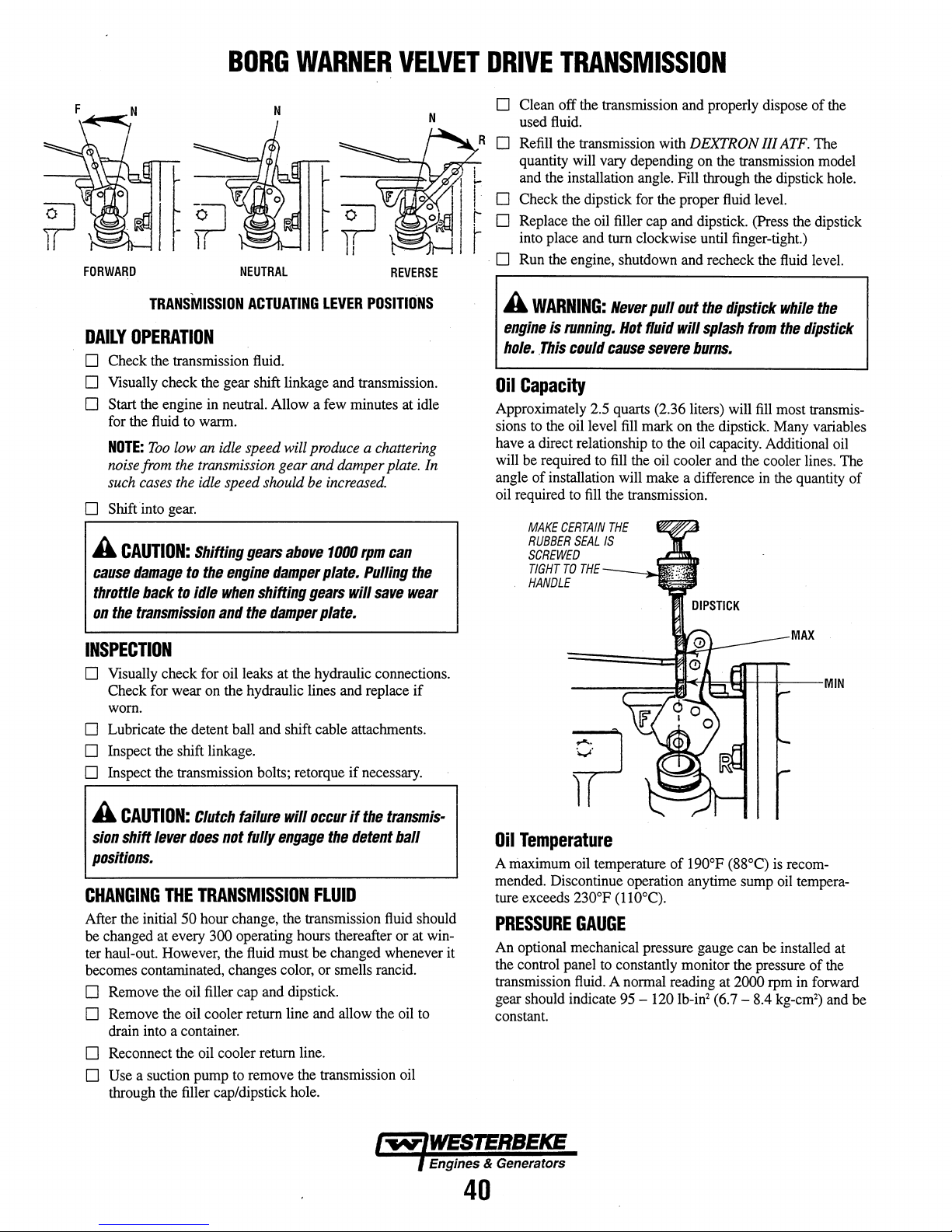
FORWARD
BORG
NEUTRAL
WARNER
VELVET
REVERSE
DRIVE
TRANSMISSION
D Clean off the transmission and properly dispose of the
fluid.
used
D Refill the transmission with DEXTRON III
quantity will vary depending on the transmission model
and the installation angle. Fill through the dipstick hole.
ATF.
The
D Check the dipstick for the proper fluid level.
D Replace the oil filler cap and dipstick. (Press the dipstick
into place and tum clockwise until finger-tight.)
. D Run the engine, shutdown and recheck the fluid level.
DAILY
OPERATION
TRANSMISSION
ACTUATING
LEVER
POSITIONS
D Check the transmission fluid.
D Visually check the gear shift linkage and transmission.
D Start the engine in neutral. Allow a few minutes at idle
for the fluid
NOTE:
noise from
such
D Shift into
A
CAUTION:
cause
damage
throttle
on
the
transmission
to
warm.
Too
Iowan idle speed will produce a chattering
the
transmission gear and damper
cases
the
idle
gear.
back
Shifting
to
the
to
idle
speed should be
gears
engine
when
and
damper
shifting
the
damper
above
plate.
gears
plate.
increased.
1000
will
plate.
rpm
can
Pulling
save
In
the
wear
INSPECTION
D Visually check for oil leaks at the hydraulic connections.
Check for wear on the hydraulic lines and replace
worn.
D Lubricate the detent ball and shift cable attaclunents.
D Inspect the shift linkage.
D Inspect the transmission bolts; retorque
if
necessary.
if
A
WARNING:
engine
is
running.
hole . .This
Oil
Capacity
Approximately 2.5 quarts (2.36 liters) will
sions
to
the oil level
have a direct relationship
will
be
required
angle of installation will make a difference in the quantity of
oil required
MAKE
CERTAIN
RUBBER
SCREWED
TIGHT
TO
HANDLE
Never
pull
out
the
dipstick
Hot
fluid
will
splash
could
cause
severe
burns.
fill
mark on the dipstick. Many variables
to
the oil capacity. Additional oil
to
fill
the oil cooler and the cooler lines. The
to
fill
the transmission.
THE
SEAL
IS
THE-_~!l<:
---;::::=:;I*tt~tt4::--MIN
while
from
the
fill
most transmis-
MAX
the
dipstick
A
CAUTION:
sion
shift
positions.
CHANGING
After the initial 50 hour change, the transmission fluid should
be
changed at every 300 operating hours thereafter or at winter haul-out. However, the fluid must be changed whenever it
becomes contaminated, changes color, or smells rancid.
Clutch
failure
lever
does
not
THE
TRANSMISSION
fully
will
occur
engage
FLUID
D Remove the oil filler cap and dipstick.
D Remove the oil cooler return line and allow the oil
drain into a container.
D Reconnect the oil cooler return line.
D Use a suction pump
through the filler cap/dipstick hole.
to
remove the transmission oil
the
if
the
detent
transmis-
ball
to
Engines & Generators
40
Oil
Temperature
A maximum oil temperature of 190°F (88°C)
mended. Discontinue operation anytime sump
ture exceeds
PRESSURE
An optional mechanical pressure gauge can
the control panel
transmission
gear should indicate
constant.
230°F (110°C).
GAUGE
be
to
constantly monitor the pressure of the
fluid.
A normal reading at 2000 rpm in forward
95 -120
Ib-in2 (6.7 - 8.4 kg-cm
is
recom-
oil
tempera-
installed at
2
)
and
be
Page 47
BORG
WARNER
VELVET
DRIVE
TRANSMISSION
MAINTENANCE
Transmission maintenance
housing clean, check
routine, and change
Periodically inspect the transmission
and
corrosion. Make certain the air vent
checking
(fluid
will
the
fluid
appear
level look for signs of water contamination
as
is
minimal.
the
fluid
level
as
the
fluid
every 300 operating hours.
and
strawberry cream).
Keep
the
exterior
part of your regular
the cooler for leaks
is
clear
and
when
Lay-up/Winterize
Storage requires special care. Follow these procedures:
o Drain the water
replace it with a proper mixture of antifreeze coolant.
NOTE:
This
raw
water cooling system
o Clean
o Fill
up
(use heat resistant paint).
the
transmission
vent internal corrosion.
o Loosen attaching hardware
output
flange
removing the boat from
and spray with lubricant.
o Inspect
Look for corrosion of
the
all
the
conduit, and bending of the actuator
moving parts.
from
the
transmission oil cooler
operation will usually occur
is
properly
the
transmission and touch-up unpainted areas
with
Dextron
from
and propeller shaft coupling
the
water.
gear shift cable, linkage, and attachments.
the
end
fittings,
when
the
winterized.
III ATF
the transmission
Separate
fluid
flange
the
flanges
cracks or cuts
rods.
Lubricate
and
to
engine
pre-
before
in
WARRANTY
Service manuals are available
dealer.
For assistance, contact:
Richmond and
1208
Liberty,
Tel.:
BORG
placed
operation or fully reversing of
shifting. Therefore torque loads and directional changes
should be made
failure
denied.
be
A
CAUTION:
occur
resulting
BORG
related
If
any
problems occur with
TRANSMISSION TROUBLESHOOTING
NOTES
Old Norris Road
SC
(800) 583-4327
WARNER
on
its gears
at
was
caused
at
low
engine
in
damage
WARNER
is
torsional
from
your
BORG
Velvet
Drive
29657
is
aware of the shock loads that can
as
the
result of mechanical propeller
the
propeller blades while
low engine speeds.
by
a shock load,
System-related
speeds
to
not
vibration
which
the
engine
responsible
of
the
If
it
is
any
warranty claim will
noises
or
can
cause
and/or
for
total
this
type.
transmission,
in
found
vibrations
transmission.
system-
see
this
WARNER
be
that a
gear
rattle
manual.
can
NOTE:
If
the
transmission
(twelve
fluid
OIL
The continued
time,
occur.
following
1. Transmission
fail.
2.
Either case requires
1. Install a
2.
Refill
months or
to
prevent internal
before
putting
the
COOLERS
flow
of
erode
the
inside of
These internal cooler leaks will cause one of
two
problems:
fluid
and
be discharged overboard through
A
loss
of
transmission fluid will
The
raw
water will leak into
causing
contaminated
transmission will eventually
an
increase
new
the
transmission
fluid
oil
an
cooler.
is
to
be
more),
it should
corrosion.
engine back into
raw
water through
the
cooler causing cross leaks
will leak into
in
transmission
will appear
immediate response:
with
the
cause
the
transmission
as
fail.
DEXTRON III
stored for a
be
topped offwith
Reduce
service.
the
flow
the
fluid.
strawberry cream.
long
the
fluid level
cooler
will,
the
of
raw
water
engine exhaust.
the
transmission
fluid
This
ATF.
time
to
The
in
to
If water
needs
take several
Check your dipstick each time until it appears
transmission
out
If
need
A transmission cooler
some
waters, maintenance,
WESTERBEKE recommends having a spare cooler
has
contaminated
to
be cleaned out
fluid
changes
fluid.
the
fluid
lines that connect
the
transmission
the
attention of a qualified transmission service
circumstances, depending on operating hours, tropical
the
fluid,
the transmission
and
replaced with fresh
to
get rid of
Change the transmission
to
fails
to
shift properly, it
may
last
etc.
it might only last half that
the
the cooler.
ten
years or more but,
fluid.
contamination.
as
pure
filter
and
will
most likely
fluid
It
will
clean
facility.
in
time.
aboard.
Engines & Generators
41
Page 48

ZF
MARINE
DESCRIPTION
The infonnation
the TRANSMISSION
applies
to
CONNECTION
HBW
recommend a flexible
transmission
flexibly
deflections. The installation of a special propeller thrust
bearing
taken
specified under SPECIFICATIONS
However,
additional
torsional
certain
Even
coupling
gearbox
wooden
output
mounted,
is
by
to
with
bearings
boats
flange
below
is
specific
TROUBLESHOOTING SECTION
all
models.
OF
GEAR
gearbox
not required, since the propeller thrust will be
the
transmission bearing, provided
the
output shaft should be protected
loads.
vibration.
observe
the
or
"DRIVESAVER"
and
and
the
in
order
Special care should be taken
When using a universal joint shaft,
the
manufacturers instructions.
engine solidly
caused
by
or
where
the
stem gland
to
the
ZF Transmissions,
BOX
WITH
PROPELLER
connection between the
propeller shaft if
to
compensate for-angular
is
not exceeded.
mounted,
will reduce stress
hull
distance between transmission
is
the
distortions, especially
less
than
../"
the
use
about
ZF
the
engine
value
from
to
prevent
of
flexible
in
the
800mm.
15M
TRANSMISSIONS
NOTE:
When
installing
is
not impeded
cable
or
rod
too
small
a bending
control
housing.
Refer
CABLES
transmission
loosening
moved
or
rod
between
actuating shift lever
lever,
for
amount
is
shorter,
in
tum,
slow
clutch
Checkfor proper lever travel at least
is
the
to
any
position required for
linkage).
the
actuating lever cover
lever
cable
or
the
with
travel,
between
and
B should be at least
the
inner pivot
of shift lever travel
and
is
recommended.
proper
would
and
clutch
engagement or
is
make
in
shifting
Bowden
sheaves,
support for shift
threaded holes located
gear
CONTROL
The
Upon
be
(cable
not contact
distance
The control
the
neutral position of
should coincide
The shifting
actuating
positions A
30mm
A greater
detrimental
travel
which,
generation
by
NOTE
the
transmission,
by
restricted movability
linkage,
to
suitable for single lever
retaining
rod
the
as
measured at the pivot point of
mean
plate
by unsuitably positioned
radius,
cable
connections,
above
the
the
WESTERBEKE
screw,
Make
certain that
and
cover should
should be arranged
when
in
the
operating lever
neutral position of
the
neutral position
point.
clutch
engagement
premature
failure.
no
make
etc.
In
order
use
shift cover
parts
the
actuating
the
control
the
plate:
the
be
neutral
position.
on
the
35mm
for
is
in
no
However,
might
wear,
This
would
engagement
each
NEUTRAL
on
remote
shift
O.5mm.
at
control
this
and
if
excessive
N
certain
of
the
to
the
two
top
of
list.
control.
lever
elements
lever
minimum
right
angle
lever.
end
the
outer
way
the
lever
be
1;>e
indicated
at
all.
season.
that
guide
mount a
the
can
does
to
The
console
the
and
impeded
heat
A
CAUTION:
the
actuating
shift1ever
this
mechanism
transmission
The
lever
travel
from..-neutral
is
warranty
position
is
of
factory-adjusted
position A and
in
any
way
tampered
will
be
void.
the
mechanism
to
ensure
B.
with,
the
behind
equal
If
Engines & Generators
42
SHIFT
LEVER
O.Smm
MINIMUM
--
COVER
F
DISTANCE
Page 49

ZF
MARINE
TRANSMISSIONS
INITIAL
All
with the engine at the factory prior to delivery. For safety
reasons the fluid is drained before shipment.
Fill the gearbox with Automatic Transmission Fluid
(DEXRON II or
up to the index mark on the dipstick.
just insert the dipstick, do not screw
into the case after the fluid level is checked and tighten. Do
not forget the sealing ring under the hexhead
Check for leaks and change the fluid after the first 25 hours,
also make a visual inspection
hoses, and shift cables.
FLUI~
FLUID
Change the fluid for the first time after about 25 hours
operation, then every 250 operating hours or at least once a
year or when you change engine
Removing
Push a suction pump hose down through the dipstick hole to
the bottom
allows, use the transmission drain). Remove the drain plug
from the bottom
drain into a container, then reinstall the plug with its sealing
washer. Wipe down the transmission and properly dispose
the used fluid. After running the engine, shut down and
recheck the fluid level.
Drain
NOTE:
drain plug sealing washer. The drain plug
this sealing washer.
OPERATION
HBW
marine transmissions are test-run on a test stand
DEXTRON III). The fluid level should be
To
check the fluid level,
it
in. Screw the dipstick.
of
the dipstick.
of
the coupling, oil cooler and
"
DIPSTICK
FLUID
FLUID
LEVEL.
Intt,l
I
~
"
DRAIN
.
I
CHANGE
oiL
the
fluid
of
the housing and suck out the fluid. (If space
of
the transmission and allow the fluid to
plug
torque
When changing the fluid, take care not to lose the
20 -25
fUlbs
will leak without
nl'\lllollYllolollON
OPERATING
of
of
OPERATING
The maximum permissible ATF temperature should not exceed
230° (110°). This temperature can only be reached for a short
time.
A
CAUTION:-"
too
high,
transmission
LOCKING
Locking
required: use the gear shift lever position opposite your direction
of
position corresponding to the direction
WHEN
Rotation
being sailed, being towed, or anchored in a river,
operation
ing the battery), will have no detrimental effects on the transmission
DAILY
TEMPERATURE
thtrtransmissio" fluid
stop
the
engine
immediately
fluid.
THE
PROPELLER
of
the propeller shaft by an additional brake is not
travel for this purpose. Never put the gear shift in the
UNDER
SAIL
OR
BEING
of
the propeller without load, such as when the boat is
of
the engine with the propeller stopped (for charg-
TOWED
temperature
and
check
of
travel
of
the boat.
as
well as
is
the
OPERATION
o Check the transmission fluid.
o Visually check the gear shift linkage and transmission.
o Start the engine in neutral, allowing a few minutes at
idle to warm the fluid.
o Shift into gear.
NOTE:
from the transmission gear
the idle speed should be increased
For additional information refer to the following text
Transmission Section:
AND
Too
low an idle speed will produce a chattering noise
and
damper plate. In such cases
SHAFT
TRANSMISSION TROUBLESHOOTING.
ZF
TRANSMISSIONS
General
Gear
Ratio
(optional)
Note:
There
are a variety
of
gear
ratios
available.
Only a few
lubricating
Propeller
Direction
are
listed.
Fluid
Shaft
of
Rotation
COUPLINGS, MAINTENANCE
SPECIFICATIONS
(ZF
Standard
hardened
servo-operated
ZF
15MA
ZF
10MA
ZF
12MA
ZF
15MIV
ATF -Type A or
Right-hand
listed.
Transmission)
helical
(1.88:1
(1.79:1)
(2.63:1)
(2.13:1
rotation
gears,
multiple
or
2.63:1)
or
2.72:1)
Dextran
for
Case'
with
a
disc
- "
or
above
in
clutch
III
models
this
A
WARNING:
engine
is
running.
stick
hole.
This
Never
Hot
could
pull
out
fluid will
cause
severe
the
dipstick
splash
burns.
from
while
the
dip-
the
Engines & Generators
43
Page 50

ZF
MARINE
TRANSMISSIONS
OPERATING
A
CAUTION:
too
high,
transmission
Normal operating temperature of the transmission
should
A maximum temperature of 266
reached for a short time.
Make certain there
to
provide good ventilation and cooling.
TRANSMISSION
Coolers
ZF
15M,
The cooler
prevents
fluid.
However,
will,
in
leaks.
A transmission cooler may last ten years or more
some circumstances, depending
waters, maintenance, etc. it might only last half that
WESTERBEKE recommends having a spare cooler
TRANSMISSION
TEMPERATURE
If
the
stop
the
transmission
engine
immediately
fluid
and
fluid.
be
in the range
of
1220 F
(50"
C)
F
(130
0
to
C)
0
is
enough space around the transmission
COOLER
are
standard equipment
ZF
15MA,
ZF
15MIY,
is
a separate part of the transmission which
any
possibilities of coolant diluting the transmission
the continued
time,
erode the inside
for
the
ZF lOM;ZF
and
the
ZF
flow
of coolant thru the cooler
of
the cooler causing external
on
operating hours, tropical
temperature
check
the
fluid
b~
only
12M,
but,
time.
aboard.
in
0
C).
2120 F (100
may
25M.
is
MAINTENANCE
Transmission maintenance
housing clean, check
routine, and change
Periodically inspect the transmission
and corrosion. Make certain the air vent
checking the
(fluid will appear
fluid
level look for signs of water contamination
as
Lay-up/Wi.nterize
Storage requires special care. Follow these procedures:
o Drain water from the transmission oil cooler
with
a proper mixture of antifreeze coolant.
NOTE:
This
operation will normally occur
engine
raw
water cooling system
o Clean
up
the
transmission
(use
heat resistant paint).
o Fill the transmission
prevent internal corrosion (extended storage
months or
more).
is
minimal.
the
fluid
level
as
the
fluid
every 300 operating
strawberry cream).
and
touch
with
Dextron III ATF
Keep
the exterior
part
of
your regular
hours.
and
the cooler for
is
clear
and
when
and
replace
when
the
is
properly winterized
up
unpainted
fluid
to
only,
leaks
areas
twelve
o Loosen attaching hardware from the transmission output
flange
and propeller shaft coupling
removing
and spray
the
with
boat
from
lubricant.
the
o Inspect the gear shift cable, linkage,
Look for corrosion of the end
the conduit, and bending of the actuator
all moving
NOTE:
(twelve months or
fluid
before putting
parts.
lfthe
transmission
to
prevent internal
the
is
more),
it should
corrosion.
engine back into service
flange
water.
Separate
and
fittil').gs,
to
cracks
be storedfor a
be
topped offwith
Reduce
before
the
flanges
attachments.
Qr
cuts
rods.
Lubricate
long
the
fluid level
in
time
·PERIODICALLY
EROSION
AND
INSPECT
LEAKAGE
FOR
Engines & Generators
44
For additional information
ZF MARINE
ZF Industries
Marine
3131
SW
Lauderdale,
Fort
Tel.:
(954)
Fax:
(954)
GEAR
US
Headquarters
42nd Street
581-4040
581-4077
FL
33312
'-t---GEAR
.
SHIFT
contact:
Page 51

THE
MODEL
FITTING
720
HAS A BREATHER
ON
THE
TOP
OF
THE
CASE
PRM
--.rllD,"nrV
NEWAGE
MODEL
A
8MM
"
.'
SEAUNG
WASHER
MODELS
7/2"
HEX
80
HEX
.
PLUG
(MODEL
720
USES
PLUG)
. drain plug sealing
FULL
LOW
~
'~NOTE:
~
TRANSMISSIONS
80
AND
120
Push
a suction
to
the bottom of
allows,
from
the
and
allow
plug
with
properly
shut down
NOTE:
When
this sealing
A
WARNING:
engine
hole.
DAILY
o Check
0 Visually check
o Start the engine
idle
0 Shift
from
the
the
idle speed should
GEAR
SHIFTING
The engine must be
selecting
120
are ideal
both
the
pump
hose
the
housing
use
the
transmission
bottom
dispose
of
the
fluid
its sealing
of
and
re-check
changing
washer.
the
transmission
to
drain
washer.
the
used
the
the
washer.
Never
is
This
running.
could
Hot
cause
OPERATION
the
transmission
the
gear shift linkage
in
neutral,
to
warm
the
fluid.
into
gear.
Too
low
an idle speed will produce a
transmission gear
be
at
idle. Pause
ahead
or
astern.
for
single lever engine controls,
throttle
and
the
down
and
drain).
into a container,
Wipe
fluid.
fluid
fluid,
The
drain plug will leak without
pullout
fluid
will
severe
fluid.
allowing a
and
damper plate.
increased
Transmission
gear shift at
through
suck out
Remove
(I"
down
After
level.
take
care
the
dipstick
splash
burns.
in
neutral
one
the
dipstick
the
the
with
then
the
transmission
running
not
from
and
few
chattering
models
time.
hole
fluid.
(If
space
drain
plug
sealing
washer)
reinstall
the
engine,
to
lose
the
while
the
the
dipstick
transmission.
minutes
In
before
PRM
controlling
such
at
noise
cases
80
the
and
and
INITIAL
Remove the dipstick
transmission
with
Model PRM80-1.0
Model
NOTE
filling with
Run
the
CHANGING
Change
operation,
a year or
make a
coupling.
OPERATION
fluid
(ATF)
the
recommended capacity of
PRM
120-1.4 U.S. pints
Always clean the
fluid.
Replace
the
engine
to
warm up
engine,
re-check the
THE
the
fluid
for the
then
every 250 operating
when
you
visual
inspection of
and
fill
the
gear box
Dextron
U.S.
pint
area
the
fluid
TRANSMISSION
first
change engine
m.
Fill
fluid.
(0.6L).
(0.8L).
around the dipstick plug before
dipstick by screwing it
the
fluid
and
level.
FLUID
time after about
hours
oil.
Check
the
shift
cables
with
automatic
the
transmission
after
shutting
25
or at least
for
and
hours
leaks
shaft
down.
down
of
once
and
A
WARNING:
throttle
ahead
LOCKING
Locking of
required:
direction of
in
the position corresponding
boat.
WHEN
Rotation of
is
being
operation of
charging
transmission
to
or
astern.
THE
the
use
UNDER
sailed,
the
When
idle
and
pause
PROPELLER
propeller shaft
the
gear shift lever position opposite
travel
for
this
SAIL
the
propeller without
being
towed,
the
engine
battery),
will
shifting
purpose.
OR
BEING
with
have
gears,
in
neutral
by
an
additional
Never put
to
the direction of
TOWED
load,
or anchored
the
propeller
no
detrimental
bring
before
such
as
in a river,
stopped
the
engine
shifting
brake
your
the
gear
travel
when
as
(for
effects
is
of
the
well
on
not
shift
the
boat
as
the
Engines & Generators
45
Page 52

PRM
NEWAGE
TRANSMISSIONS
CONTROL
NOTE:
shifting
Bowden
sheaves,
The
the actuating shift lever
CABLES
When
installing
is
not impeded
cable
or
too
small
control
cable or rod should be arranged
the
l:Jy
rod
linkage,
a bending
when
transmission,
restricted
l:Jy
unsuitably
radius,
in the neutral position. The
neutral position of the operating lever
coincide
should
The
shifting
actuating
positions A
30mm
for
with
the neutral position of
travel,
as
measured
lever,
between the neutral position
and
B should be at least
the inner pivot point
at
the pivot point of
35mm
TROUBLESHOOTING
Problem
Excessive
Excessive
Difficulty
Escape
when
Fluid
noise
noise
needs
in
moving
of
pressure
dipstick
at
low
at
all
constant
lever
from
is
removed
speeds
speeds
topping
control
gearbox
off
make
movability
positioned
etc.
at
on
the
control console
this
and
for
Probable
1.
Engine
1.
Defective
Shaft
2.
Prop
out
3.
Power
1.
Ruid
leak
2.
1.
Poor
installation
Faulty
2.
Defective
1.
(Model
MODELS
certain
that
of
the
guide
right angle
lever.
end
the outer
idle
speed
coupling
misalignment
of
balance
too
high
cable
breather
120)
the
and
Cause
too
of
cable
to
low
80
AND
. A greater
detrimental
travel
which;
generation
by
NOTE
120
ACTUATING
SHIFT
LEVER
amount
is
shorter,
in
tum,
and
slow
clutch
Checkfor
1.
1.
2.
3.
1.
2.
1.
2.
1.
N
NEUTRAL
30
'
I r
\ : I '
;11\ © tI;.!=i.
< !!)1' 0
~,
~D'
~.
\
of shift lever
and
is
recommended.
proper
would
mean
clutch
plate
engagement
proper
lever
Verification/Remedy
Increase
idling
InspecVreplace
Check
alignment
Remove,
check
Compare
engine
Inspect
seals,
InspecVreplace
Check
alignment
Inspect
breather
WESTERBEKE
I
35·.......:
.1
30'11
..
J!
#~t:I;::1
/'
. i
travel
==:=::I~
II
SHIFT
is
in
However,
clutch
engagement
premature
failure.
or
travel
speed
coupling
with
pitch,
and
drain,
coupling
with
(Model
dealer
no
feeler
balance
transmission
check
feeler
wear,
This
would
engagement
at least
if
necessary
gauge
and
weight
data
for
fluid
leaks
if
necessary
gauge
120),
contact a Distributor
CABLE
no
way
if
the
might
excessive
be
at
each
AND
BRACKET
lever
be
impeded
indicated
all.
season.
or
heat
your
MAINTENANCE/SERVICE
Make certain the transmission
If
the
fluid
should become contaminated
suffers
gearbox
must
be
major mechanical damage, the gearbox
thoroughly
flushed
to the correct specifications. .
NEWAGE
the
Atlantis
418
Topsfield,
Tel:
Fax:
Hamilton
1111
Seattle,
Tel:
Fax:
Transmission
223
P.O.
Ft.
Lauderdale,
Tel:
Fax:
Or
TRANSMISSIONS
world.
Listed here are those in the United States.
Marine
Gear
Boston
Street
MA
978-887-0001
978-887-5599
Jet
NW
Ballard
WA
206-784-8400
206-783-7323
Southwes133
Box
21086
954-467-1540
954-467-1525
contact your
01933
Way
98107
.Marine
FL
Supply
Court
33335-1086
Westerbeke
Inc.
fluid
out
dealer.
and
LTD.
is
changed
re-filled
has
annually.
by
water or the
with
distributors around
fresh
fluid
If
a major
problem
should
occur,
dealer or a NEWAGE distributor.
warranty rights,
gearbox without
TRANSMISSIONS
or your
WESTERBEKE
do
not undertake repair
first
contacting NEWAGE
liMITED
or a NEWAGE distributor
dealer.
Warranty
Newage
Transmissions
worlananship under
twenty-four
All
and
transmission
months.
PRM
Transmissions
maintained.
will
limited
be
free
normal
from
use
must
warrants
be correctly
contact your
To
avoid prejudicing
work
that
defects
in
material
and
service
installed,
Westerbeke
on
the
all
PRM
Newage
and
for a period
aligned,
or
Engines & Generators
46
Page 53

TRANSMISSION
TROUBLESHOOTING
I
CONTROL
The
improper
problems
rather
PRM
cable
If
you
shut
level,
the
full
neutral,
observe
is stiff
and
CABLES
majority
the
try
of transmission difficulties arise
clutch
With
than
from
clutches,
adjustments.
experience
engine
then
have
range -from
into
full
the
actuating lever
to
operate,
again.
adjustments (manual transmissions) or
control cables (hydraulic transmissions)
problems
in
particular, are
operating problems
down.
a helper move the cockpit shift lever
reverse,
break the cable loose
If
it
is
still stiff, check
excessively tight bends,
Problem
Transmission
Fails
Transmission
but
fails
Delay
only
Transmission
Chattering
mainly
Boat
Oil
Leakage.
to
move
to
propel
of
gear
after
an
transmission
at
low
fails
to
gears
cannot
into
gear.
shifts
into
gear,
the
boat.
engagement
increase
in
speed.
noise
becomes
engine
attain
noise,
speed.
specified
with
the transmission
very
First check
neutral
to
and
back
on
the
and
check
be
shifted.
or
engages
louder.
max.
speed.
sensitive
with
the transmission,
the
transmission-fluid
full
forward,
to
neutral - while
transmission.
at
the transmission
the
cable for
any
linkage for
Probable
1.
Actuating
2.
Shifting
unattached.
3.
Shift
lever
1.
Output
2.
Propeller
Output
3.
Output
propeller
Lever
1.
Refer
2.
Shift
level
Shift
lever
3.
1.
Damage
to
wear
misalignment
driveshaft.
Beginning
2.
transmission
running
alignment
engine
The
engine
1.
vibrations
a
·chattering"
Operating
1.
2.
Operating
Corrosion
1.
Damaged
Misalignment
2.
as
a result of
itself.
to
improper
through
back
to
you
If
the
remote
kinks
or
binding.
Cause
lever
is
loose.
cable
is
broken,
Cable
radius
is
binding
coupling
is
not
shaft
is.not
coupling
is
tuming.
coupling
and
shaft
are
turning.
travel N to B not
to
diagram.
travel
in
insufficient.
is
binding
starting
on
or
without
output.
temperature
sealing
flexible
fatigue,
possibly
between
damage
of
due
to
torsional
fluid,
of
transmission,
or
propeller
in
the
drive
noise
in
without
cooling.
at
radial
sealing
ring.~
of
output
bent
is
too
against
cover
tuming.
turning.
equal
to N to
against
cover
coupling
due
engine
bearings
overload,
or
generates
unit
which
the
transmission.
is
high.
ring
flanges.
A
new
needed.
out
of gear
make
If the
have
the
propeller
needs
thrust,
the
shaft
that
NOTE:
immediately
authorized
or
severe.
plate.
A.
plate.
due
to
and
in
vibrations,
wrong
excessive
torsional
produces
and
shaft.
cable
and
perhaps a new
While the
sure
there's
transmission
a helper put it
professional
check
or,
it isn't stuck
If
you suspect a major problem
cable
using
the lever
no
passes
in
shaft;
if
attention.
to
see
you
if
you
have
in
the
contact your
marine
transmission
is
loose,
on
binding
these
forward
the
shaft
still
a folding or
"no
WESTERBEKE
Verification/Remedy
1.
Tighten
damping
bolt
2.
Check
the
cable,
reattach
3.
Detach
the
shift
Clearance
1.
Transmission
2.
The
coupling
on
the
pins
and
3.
Inspect
A
folding
propeller
1.
Adjust
Refer
to
2.
Check
3.
Check
1.
Check
inspect
engine.
2.
Transmission
Mount a flexible
1.
between
A
higher
Inspect
2.
transmission.
Wrong
1.
2.
Check
Transmission
1.
2.
Check
cable
should
needs
bolts
propeller
shaft.
coupling
the
propeller.
propeller
may
be
cover
plate
SHIFT
LEVER
shift
lever
clearance,
alignment,
the
damper
Replace
if
needs
coupling
the
transmission
stiffness
the
damper
Replace
type
of
fluid.
cooler.
Inspect
needs
alignment.
be
in
cable
adjust
inspect
Must
linkage
shift
the
side
inside
tests,
and
reverse
isn't
turning,
If it
does
have
a propeller
pitch"
position.
facility.
on
shifting
or
replace.
and
operate
0.02
in
(0.5mm).
professional
are
sheared
Tighten
bolts
as
necessary.
It
may
be
may
be
jammed. A variable
"no
pitch"
until
the
lever
TEXT
AND
length.
if
necessary.
flexible
plate
between
necessary.
professional
with
coupling
factor
might
plate
between
if
necessary.
Use
ATF.
coolant
professional
be
within
mechanism
the
transmission
of
the
transmission
the
case.
crank
the
while
the
turn but there's
on
feathering
in
your
transmission,
dealer
lever.
the
lever
attention.
or
the
coupling
or
replace
set
missing
or
damaged.
position.
is
exact
mid-position.
DIAGRAM.
See
SHIFT
LEVER
coupling.
the
transmission
attention.
another
stiffness
with
and
be
sufficient.
the
engine
Check
fluid
level.
hoses
and
coolant
attention.
0.003
in
(O.OBmm).
may
in
engine
and
you
observe
transmission
no
the
end
of
propeller,
or
an
by
hand.
is
Slipping
screws,
keys,
pitch
DIAGRAM.
If
noise
persists,
and
the
factor
the
driveshaft.
and
the
flow.
be
and
to
NOTE:
If
you
suspect a major problem
immediately
authorized
contact your
marine
transmission
WESTERBEKE
facility.
in
your
dealer or
transmission,
an
Engines & Generators
47
Page 54
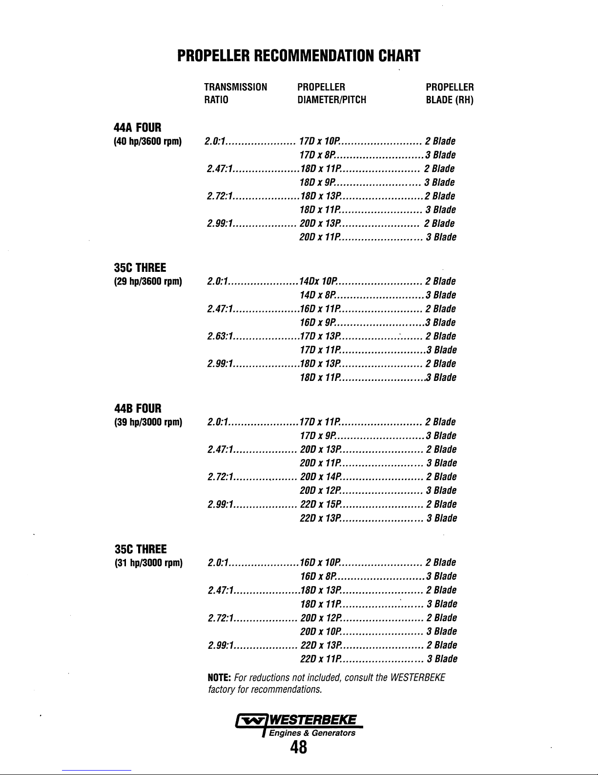
PROPELLER
RECOMMENDATION
CHART
44A
(40
hp/3600
35C
(29
hp/3600
FOUR
rpm)
THREE
rpm)
TRANSMISSION
RATIO
2.0:1
••....•..•............
2.47:1
.......•...•.........
2.72:1
....................•
2.99:1
....................
2.0:1
.....•........•...•..•
2.47:1
•...............•...•
2.63:1
.....................
2.99:1
..•..................
PROPELLER
DIAMETER/PITCH
170 x 10P.
170 x BP.
1BO x 11P.
1BO x 9P.
1BO x 13P.
1BO x 11P.
200 x 13P.
200 x 11P.
140x
140 x BP.
160 x 11P.
160 x 9P.
170 x 13P.
170 x 11P.
1BO x 13P.
1BO x 11P.
....•.................... 2
..••...................•... 3
.......•.••....•........ 2
..••....•....••........•.. 3
...............•.•.....•. 2
....•..................•. 3
.........•.............. 2
......•.....•.•..•.•..... 3
10P.
.•.....•...••.....•••..... 2
•........................•. 3
..•..........••........•. 2
........................... 3
......•....•..... : ....... 2
.••.........•••......•.... 3
.....••....•.....•......• 2
..•....•....•..........•.
PROPELLER
BLADE
(RH)
Blade
Blade
Blade
Blade
Blade
Blade
Blade
Blade
Blade
Blade
Blade
Blade
Blade
Blade
Blade
.3
Blade
44B
(39
hp/3000
35C
(31
hp/3000
FOUR
rpm)
THREE
rpm)
2.0:1
•....•........•.......
2.47:1
..•..•..............
2.72:1
•.......•..•........
2.99:1
...•....•...........
2.0:1
......................
2.47:1
....•................
2.72:1
....................
2.99:1
..•...•.............
NOTE:
For
reductions
factory
for
recommendations.
170 x 11P.
170 x 9P.
200 x 13P.
200 x 11P.
200 x 14P.
200 x 12P.
220 x 15P.
220 x 13P.
160 x 10P.
160 x BP.
1BO x 13P.
1BO x 11P.
200 x 12P.
200 x 10P.
220 x 13P.
220 x 11P.
not
included,
.........••............•• 2
•....•..................•.. 3
.......................•. 2
.......................•. 3
•....•••....•......••.... 2
•.•...............•••.... 3
•...........•.....•••.... 2
...•....••............... 3
•....•.....••......•..... 2
...•.........••.....•...... 3
.••....•.............•... 2
..•.........••... : •••.... 3
...........••............ 2
........•................ 3
...•...........••.......• 2
....•...........•........ 3
consult
the
WESTERBEKE
Blade
Blade
Blade
Blade
Blade
Blade
Blade
Blade
Blade
Blade
Blade
Blade
Blade
Blade
Blade
Blade
Engines & Generators
48
Page 55

LAY-UP & RECOMMISSIONING
General
Many owners rely on their boatyards to prepare their craft,
including engines and generators, for lay-up during the offseason or for long periods
accomplish lay-up preparation themselves.
The procedures which follow will allow you to perform your
own lay-up and recommissioning, or will serve as a checklist
if
others do the procedures.
These procedures should provide protection for your
engine/generator during a lay-up and also help familiarize
you with its maintenance needs.
If you have any questions regarding lay-up procedures, call
your local servicing dealer. He will be more than willing to
provide assistance.
Propeller
The transmission and propeller half couplings should always
be opened up and the bolts removed when the boat is hauled
out
of
storage
severe strain on the propeller shaft or coupling or both, while
the boat is taken out or put
shaft has actually been bent
apply to small boats that are hauled out
not in use, unless they have been dry for a considerable
period
Fresh
A 50-50 solution
mended for use
This solution may require a higher concentration of antifreeze,
depending on the area's winter climate. Check the solution to
make sure the antifreeze protection
Should more antifreeze be needed, drain an appropriate amount
from the engine block and add a more concentrated mixture.
Operate the engine to ensure a complete circulation and mixture
system. Then recheck the antifreeze solution's strength.
Lubrication
With the engine warm, drain all the engine oil from the oil
sump. Remove and replace the oil filter and fill the sump
with new oil.
Shaft
the water or moved from land to water, and during
in
the cradle. The flexibility
of
time.
Water
of
the antifreeze concentration throughout the cooling
Cooling
of
in
the fresh water cooling system at all times.
System
Use the correct grade
ENGINE LUBRICATING
"engine oil change".
Run the engine and check for proper oil pressure and make
sure there are no leaks.
of
inactivity. Others prefer to
Coupling
[Propulsion
of
the boat oftens puts a
in
the water. In some cases, the
by
these strains. This does not
of
the water when
Circuit
antifreeze and distilled water
is
adequate.
of
oil. Refer to the
OIL
pages
in
this manual for
Engine]
is
recom-
Fuel
System
Top off your fuel tanks with unleaded gasoline
or higher. A fuel conditioner such as
stabilizer should be added. Change the element
gasoline/water separator and clean the metal bowl.
Re-install and make certain there are
up
any spilled fuel.
Fuel
System
Top off your fuel tanks with No.2 diesel fuel. Fuel additives
BlOB
such as
control algae and condition the fuel. Care should be taken
that the additives used are compatible with the primary fuel
filter/water seperator used
in
your primary fuel filter/water seperator,
has one, and clean the seperator sediment bowl.
Change the fuel filter elements on the engine and bleed the
fuel system, as needed. Start the engine and allow it to run
for 5 -
10 minutes to make sure no air is left
system. Check for any leaks that may have been created
the fuel system during this servicing, correcting them
needed. Operating the engine for 5 - 10 minutes will help
allow movement
equipment on the engine.
Raw
Water
Close the through-hull fitting. Remove the raw water intake
hose from the fitting.
gallon bucket
check the zinc anode found
the engine and clean or replace it
any zinc debis from inside the heat exchanger where the zinc
anode is located. Clean the raw water strainer.
Start the engine and allow the raw water pump to draw the
fresh water through the system. When the bucket
stop the engine and refill the bucket with an antifreeze
solution slightly stronger than needed for winter freeze
protection
Start the engine and allow all
through the raw water system.
the engine. This antifreeze mixture should protect the raw
water circuit from freezing during the winter lay-up, as well
as providing corrosion protection.
Remove the impeller from your raw water pump (some
antifreeze mixture will accompany it, so catch it
Examine the impeller. Get a replacement,
cover gasket. Do not replace the impeller (into the pump)
until recommissioning, but replace the cover and gasket.
[Gasoline]
of
STABIL
no
[Diese~
OR
and
STABIL
of
the treated fuel through the injection
Cooling
Place the end
of
clean fresh water. Before starting the engine,
in
your area.
should be added at this time to
in
the system. Change the element
Circuit
of
in
the primary heat exchanger on
as
required and also clean
of
this mixture to be drawn
Once the bucket is empty, stop
gasoline
leaks. Clean
if
the fuel system
in
the fuel
this hose into a five
if
needed, and a
89
in
your
is
empty,
in
a bucket).
octane
in
as
A
CAUTION:
oil
in
the
combustion
chemicals
internal
parts.
sump
over
depOSits
which
Do
not
the
combine
can
leave
lay-up
reduce
th~
engine's
period.
to
produce
the
life
of
old
Engine
harmful
your
engine's
engine
oil
and
Engines
49
Intake
Place a clean cloth, lightly soaked
opening
shove the cloth out
recommissioning, and an attempt is made to start the engine,
you may need assistance
note to remove the cloth prior to start-up. The thru-hull
exhaust port can be blocked in the same manner.
& Generators
Manifold
of
the intake manifold to block the opening. Do not
and
of
sight.
of
Thru-Hull
(If
the servicing dealer). Make a
Exhaust
in
lubricating oil,
it is not visable at
in
the
Page 56

LAY-UP
&
RECOMMISSIONING
Starter
Lubrication and cleaning
advisable,
Make sure the battery connections are shut off before
attempting to remove the starter. Take care in properly
replacing any electrical connections removed from the starter.
Cylinder
If
WES1ERBEKE recommends removing the glow plugs or
fuel injectors for access to the cylinders. Squirting light
lubricating oil into the cylinders to prevent the piston rings
from sticking to the cylinder walls. Rotate the engine by hand
two revolutions then replace the glow plugs
Make sure you have a replacement
sealing washer for the
Intake
Clean the filter screen in the flame arrester, and place a clean
cloth lightly soaked in lube oil around the flame arrester to
block any opening. Also place an oil-soaked
through-hull exhaust port.
to start-up!.
Intake
Place a clean cloth, lightly soaked in lubricating oil, in the
opening
shove the cloth out
sioning, and an attempt is
need the assistance
remove the cloth prior to start-up.
port can be blocked in the same manner.
Motor
of
the starter drive pinion is
if
access to the starter permits its easy removal.
Lubrication
you anticipate a long lay-up period (12 months or more)
or"
injectors.
if
removing the injector"
~njector
Manifold
Manifold
of
the intake manifold to block the opening. Do not
[Gasoline
and
of
sight.
of
a servicing dealer.) Make a note to
and fuel
"return
J
clqth in the
Make
a note to remove cloths prior
Thru-Hull
(If
made
Exhaust[Diesel]
it
is not visible at recommis-
to start the engine, you may
The
through-hull exhaust
line.
BAnERIES
If
batteries are to be left
make sure they are fully charged, and will remain that way,
to prevent them from freezing.
the batteries will not remain fully charged, or that they will
be subjected to severe environmental conditions, remove
the batteries and store them in a warmer, more compatible
environment.
on
board during the lay-up period,
If
there exists any doubt that
Spare
Lay-up time provides a
WES1ERBEKE engine to see
Parts
good
belts or coolant hoses
spares kit and order items not
used during the lay-up,
to
SPARE
PARTS
need
section
replacement Check your basic
such
of
this manual.
opportunity to inspect your
if
external items such
on
hand, or replace those items
as filters and zinc anodes. Refer
as
drive
Recommissioning
The recommissioning
seasonal lay-up generally follows the same procedures as
those presented
section regarding preparation for starting and normal starts.
However, some
counteracted before starting the engine.
1.
Remove the oil-soaked cloths from the intake manifold
2. Remove the raw water
the old gasket. Install the
removed during lay-up (or a replacement,
Install the raw water
3. Reinstall the batteries that were removed during the layup, and reconnect the battery cables, making sure the
terminals are clean
Check to make sure that the batteries are fully charged.
A
CAUTION:
and
eye
protection
batteries
can
cigarette,
open
all
electrical
4. Remove the spark plugs,
proper tightness
emit
be
ignited
cigar,
flame
near
electrical
arcing
of
your
WES1ERBEKE engine after a
in the
PREPARATIONS
of
the lay-up procedures will
pump
cover and gasket. and discard
raw
water pump impeller
pump
cover
and
that the connections are tight.
Wear
rubber
gloves, a rubber
when
servicing
hydrogen,
by
Dr
the
equipment
during
[gasoline].
a highly
electrical
pipe.
Do
battery
in
servicing.
wipe
arcing
not
smoke
being
the
vicinity
clean, re-gap, and install to
FOR
STARTING
need"
to be
if
required).
with a new cover gasket.
apron,
batteries.
explosive
Lead
gas,
acid
which
Dr a lighted
Dr
allow
an
serviced.
to
prevent
Shut
off
A
Warning:
highly-explosive
arcing
Dr a lighted
smoke
Dr
serviced.
vicinity
to
Transmission
Check
or
change the fluid in the transmission as required.
Wipe
off grime and grease and touch up any unpainted areas.
Protect the coupling and the output flange with an anti-corrosion coating. Check that the transmission vent is open. For
additional information, refer to the
SECTION.
Lead
gas,
cigarette,
allow
an
open
Shut
off all electrical
prevent
electrical
[Propulsion
acid
which
flame
batteries
can
be
cigar,
ngar
equipment
arcing
Engine
TRANSMISSION
emit
hydrogen,
ignited
the
by
electrical
Dr
pipe.
Do
not
battery
during
being
in
the
servicing~
J
a
Engines
5. Check the condition
circuit and clean or replace the anode as needed. Note that
it is not necessary to flush the antifreeze/fresh water
solution from the raw water coolant system. When the
engine is put into operation, the system will self-flush
short period
advisable, as either an
service,
heat exchanger and clear any and all zinc debris from that
area.
6.
Start the engine in accordance with procedures described
in the
this manual.
& Generators
of
to
inspect the
PREPARATIONS
of
the zinc anode in the raw water
time with no adverse affects.
end
of
season or recommissioning
area
where the zinc is located
FOR
INmALSTART-UP section
50
It
is
in
in
a
the
of
Page 57

44A & 448
FOUR
ENGINE
SPECIFICATIONS
Engine
Type
Displacement
Aspiration
Combustion
Bore & Stroke
Firing
Direction
Compression
Dimensions -inches
Engine
Weight
Fuel
Inclination
Chamber
Order
of
Rotation
Ratio
Only
Consumption
TUNE-UP
Compression
Minimum
Valve
Spilled
Valve
Engine
Valve
Valve
(engine
Injector
Engine
Pressure
liming
liming
(Static)
Seat
Angle
Speed
Seat
Angle
Clearance
cold)
Pressure
liming
SPECIFICATIONS
Diesel,
(mm)
four-cycle,
cooled,
vertical
mechanism
107.3
cubic
Naturally
Swirl
type.
3.07 x 3.62
1 -3 -
4-2
Clockwise,
22:1
Height:
18.6
Width:
23.0
Length:25.6
331
Ibs
2.5
glhr
Continuous
Temporary
in-line
..
inches
aspirated.
inches
when
viewed
inches
inches ( 584.2
inches ( 914.4
(150
kgs)
(9.7Itrlhr)
15°
25°
(not
four-cylinder,
(78 x 92
without
at
SPECIFICATIONS
427
psi
(30
psi
(27
Opens
Closes
(spill)
rpm
rpm
45°
30°
inches
BTDC
kg/cm')
kg/cm')
(44AlFour)
(44B/Four)
(0.0098
-0
psi
(140
384
I
ntake
Intake
17°
45°
3600
3000
Intake
Exhaust
0.25
1991 + 71
17°
overhead
(1.758
liter)
from
(472.4
mm)
transmission.
3600
to
exceed
at
280
mm)
+ 5 - 0
fresh
valve
mm)
the
mm)
mm)
rpm
30
rpm
kgf/cm').
water-
front.
min.)
General
Fuel
Fuel
Injection
Nozzle
Fuel
Filter
Air
cleaner
AirAow
(engine
combustion)
Fuel
Lift
Pump
General
Operating
discharge
elbow)
System
General
Temperature
Fresh
Water
Raw
Water
Raw
Water
(measured
(Fresh
Oil
Sump
(not
Operating
(engine
Oil
into
Approximate
Capacity
Water)
Filter
Capacity
including
Oil
hot)
Grade
Pump
COOLING
Pump
Pump
Flow
before
exhaust
LUBRICATION
filter)
Pressure
FUEL
SYSTEM
Open
flow,
No.2
diesel
In-line
plunger
Throttle
type.
Spin-on
replaceable.
Replaceable
140
cfm
(3.9
93
cfm
(26.2
12
volt
DC
Fresh
water-cooled
controlled
170
-190° F
Centrifugal
Positive
displacement,
belt-driven.
44AJFour
44B/Four
·8.0
US
qts
Pressure
fed
Full
flow,
paper
5.2
U.S.
qts
50 -60
psi
API
Specification
SAE
30,
10W-30,
self
priming.
oil
(cetane
rating
type
(BOSCH).
paper
filter
cartridge.
cmm)
at
3600
cmm)
at
3000
lift
capacity
of
SYSTEM
block,
with
heat
exchanger.
(77 -88°
type,
(7.6
metal
9.5
8.0
liters)
C)
impeller,
rubber
gpm
gpm
SYSTEM
system.
element,
(5.4
liters)
(3.5 -4.2
kg/cm')
CF
or
CG-4,
15W-40
of
45
or
higher).
rpm.
rpm.
5'
(1.5
mm)
solid
thermostatically-
belt-driven.
impeller,
at
3600
rpm
at
3000
rpm
spin-on
type.
state
ELECTRICAL
Starting
Battery
Capacity
Battery
DC
Charging
Alternator
Starting
Aid
Starter
12
400 -600
51
Glow
12
Volt,
Amp
plugs,
Volt,
SYSTEM
(-)
negative
Cold
Cranking
rated,
belt-driven
sheathed
reduction
ground
type
gear
Amps
(CCA)
Engines & Generators
51
Rev.
July
2002
Page 58

35C
&
350
THREE
ENGINE
SPECIFICATIONS
Engine
Type
Displacement
Aspiration
Combustion
Bore & Stroke
Rring
Direction
Compression
Dimensions -inches
Engine
Weight
Inclination
Order
of
Only
Chamber
Rotation
Ratio
TUNE-UP
Compression
Minimum
Valve
Spilled
Valve
Engine
Injector
Valve
Valve
(engine
Engine
Pressure
liming
liming
(Static)
Seat
Angle
liming
Pressure
Seat
Angle
Clearance
cold)
Speed
SPECIFICATIONS
Diesel,
(mm)
four-cycle,
cooled,
vertical
mechanism
80.4
cubic
Naturally
Swirl
type.
3.07 x 3.62
1 - 3 - 2
Clockwise,
22:1
Height:
Width:
Length:
276
Ibs
(276
Continuous
Temporary
three-cylinder,
in-line
..
inches
(1.318
aspirated.
inches
when
viewed
21.6
inches
20.1
inches
22.4inches
kgs)
without
15·
25·
(not
SPECIFICATIONS
427
psi
(30
psi
(27
Opens
Closes
(spill)
BTDC
45·
30·
inches
rpm
rpm
kg/cm')
kg/cm')
-0
psi
(140
(0.25
(35ClThree)
(35DlThree)
384
Intake
Intake
17·
45·
17·
1991 + 71
Intake
Exhaust
0.0098
3600
3000
overhead
liter)
(78 x 92
from
to
exceed
at
280
+ 5 -0
mm)
fresh
water-
valve
mm)
the
front.
(540.6
mm)
(510.5
mm)
(596
mm)
transmission.
30
min.)
rpm
kgf/cm').
General
Fuel
Fuel
Injection
Nozzle
Fuel
Riter
Air
cleaner
AirFlow
(engine
combustion)
Fuel
Lift
Pump
General
Operating
Fresh
Raw
Raw
(measured
discharge
elbow)
System
(Fresh
General
Oil
Sump
(not
Operating
(engine
Oil
Temperature
Water
Water
Water
into
Approximate
Capacity
Water)
Riter
Capacity
including
Oil
hot)
Grade
Pump
COOLING
Pump
Pump
Row
before
exhaust
LUBRICATION
filter)
Pressure
FUEL
SYSTEM
Open
flow,
No.2
diesel
In-line
plunger
Throttle
type.
Spin-on
replaceable
Replaceable
83.7
cfm
(2.3
69.7
cfm
(1.9
12
volt
DC
Fresh
water-cooled
controlled
170
-190· F
Centrifugal
Positive
displacement,
belt-driven.
35C/Three
35D/Three
5.0
US
qts
Pressure
fed
Full
flow,
paper
3.9
U.S.
qts
50 -60
psi
API
Specification
self
priming.
oil
(cetane
rating
type
(BOSCH).
paper
filter
cartridge.
cmm)
at
3600
cmm)
at
3000
lift
capacity
of
SYSTEM
block,
with
heat
exchanger.
(n
-88·
C)
type,
metal
impeller,
rubber
9.5
gpm
8.0
gpm
(4.7
liters)
SYSTEM
system.
element,
(3.7
liters)
(3.5 -4.2
CF
kg/cm')
or
CG-4,
of
45
or
higher).
rpm.
rpm.
5'
(1.5
mm)
solid
thermostatically-
belt-driven.
impeller,
at
3600
rpm
at
3000
rpm
spin-on
type.
state
ELECTRICAL
12
Starting
Battery
Battery
Capacity
DC
Charging
Altemator
Starting
Aid
Starter
Volt,
400 -600
51
Amp
Glow
12
Volt,
(-)
negative
Cold
rated,
plugs,
reduction
sheathed
SYSTEM
Cranking
belt-driven
gear
ground
Amps
type
(CCA)
Engines & Generators
52
Rev.
July
2002
Page 59

44
FOUR
AND
35
THREE
TORQUE
SPECIFICATIONS
Bolt
or Nut Diameter Pitch across flats
Alternator
Back
Connecting
Coolant
Coolant
Coolant
Coolant
Crankshaft
Cylinder
Damper
Delivery
Engine
Exhaust
Flywheel
Fuel
Fuel
Fuel
Fuel
Fuel
Glow
Glow
Intake
Main
Oil
Oil
Oil
Oil
Oil
Pressure
Rear
Rear
Retaining
Valve
Rocker
Rocker
Sliding
Special
Torque
Starter B Terminal
Stop
Thermostat
Thermoswitch
Bracket
Plate
Rod
Pump
Pump
Temperature
Temperature
Pulley
Head
Plate
Valve
Mounts
Manifold
Bolt
Filter
Assembly
Injection
Injection
Leak-Off
Solenoid
Plug
Plug
Connection
Manifold
Bearing
Filter
Pan
Bolt
Pan
Drain
Pressure
Pressure
Refief
Plate
Bolt
Plate
Bolt
Nut
Holder
Cover
Shaft
Sleeve
Nut
Spring
Solenoid
Cap
Pulley
Bolt
Holder
Nozzle
Pipe
Pipe
Locknut
Cap
Plug
Sender
Switch
Valve
(stamping)
(standard)
for
Body
Bolt
Bracket
Shaft
for
Set
Housing
Sender
Switch
Nut
Holder
Nut
Nut
Plate
Bolt
Delivery
Bolt
M9
M18
M10
M12
M20
M12
M12
M10
M4
M10
M20
M8
M14
PT1/8
M22
M8
M12
M16
M8
M8
M10
M12
M8
M30
M16
MAJOR
BOLTS
1.0
1.5
1.25
1.25
1.5
1.5
1.5
1.25
0.7
1.25
1.5
1.25
1.5
1.5
1.25
1.25
0.75
1.25
1.25
1.25
1.0
1.25
1.5
1.5
AND
NUTS
Width
14
27
14
19
19
21
18
12
8
17
12
22
26
22
12 16
17
19
12
12
14
17
12
36
17
Clamp
length
87
29
60
81
25
10
11
33
28
40
581
29.5
31.5
TORQUE
kg -m
3.8-5.3
3.3-4.8
3.55±0.25
1.6±2.4
1.6 ± 2.4
1.2±1.8
1.2±1.8
17.5±2.5 127±18
9±0.5
1.9±
2.7
4.5±0.5
3.2±4.7
1.6±2.4
13.5±0.5 98±4
4.6±6.8
5.5±0.5
3±0.5 22±4 29±5
2.75±0.25
4.0±0.5
1.75±0.25
0.125 ± 0.025
1.6±2.4
5.25 ± 0.25
1.2±0.1
2.8±0.3 20.3±2.2 27±5.3
4.0±
0.5
1.2±1.8
1 ±0.2 7.2±1.4 10±2
5.0±0.5
1.15
±0.15
6.5
±0.1
3.75 ± 0.25
1.15±0.15
1.5±0.5
3.6±0.6 26±4
2±0.5
1.1
±0.1
4.5±0.5
0.3-0.45
2.3±0.4
ft - Ib
27-38
24-35
27±72
12-17
12-17
9-13
9-13
65
± 4 88± 5
14-20
32±54
23-34
12-17
33-49
40±44
20± 2
28.9±36.2
12±72
0.9 ± 0.2
12-17
38±2 51.5±2.5
8.7±
29±4 39±5
9-13
36±4 49±5
8.3±1.1
47±7 64±10
27±2 37±2.5
8.3±1.1
11
±4
14±4
80±7
32±54
2-3
16.6
± 3
0.7
N-m
36.6
32.5
34.8±2.5
17.2
17.2
12.2
12.2
172±25
8.9
44± 5
31.1
7.2
132±5
44.7
54±5
27±2.5
39.18
17.2±2.5
1.2±0.2
16.2
12±1
12.2
11.3
±1.5
11.3±1.5
14.7
± 5
35±6
20±5
10.8±1
44±5
2.7
22.6
± 4
Engines & Generators
53
Page 60
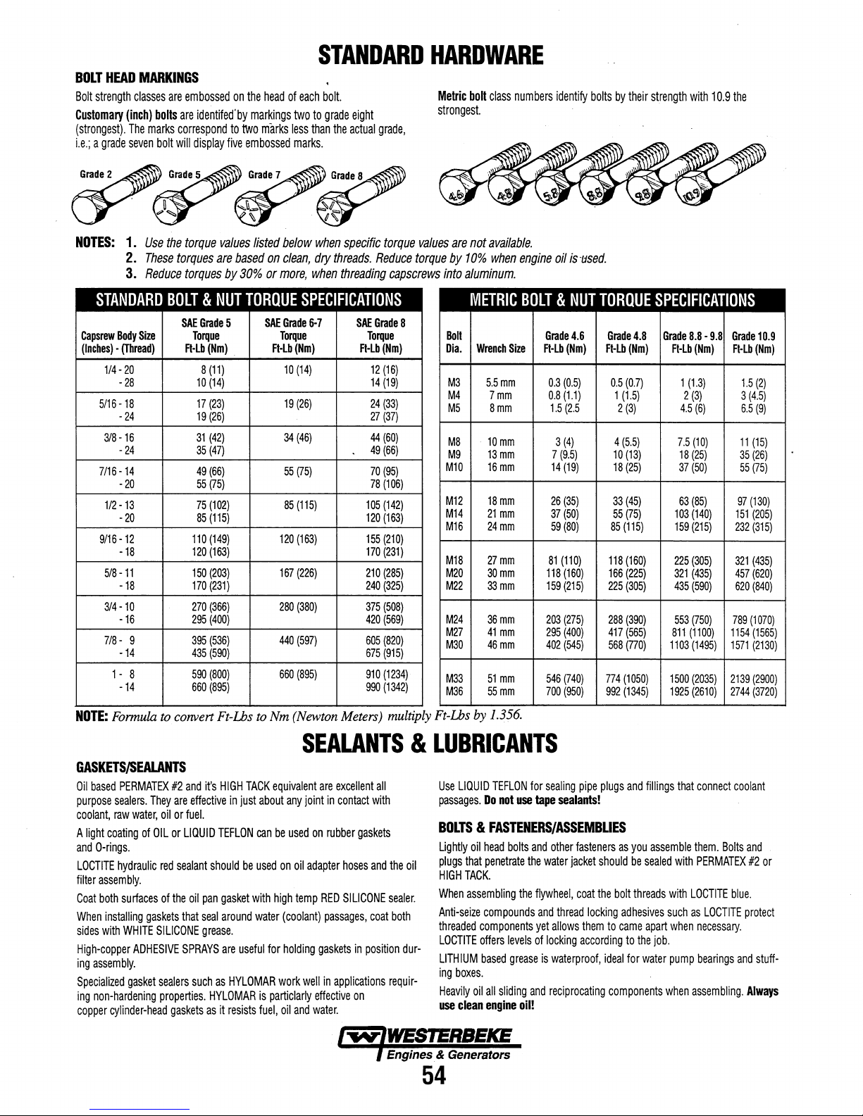
BOLT
HEAD
Bolt
strength
Customary
(strongest),
Le,; a grade
MARKINGS
classes
are
(inch)
bolts
are
The
marks
seven
correspond
bolt
will
embossed
identifed'
display
five
on
the
by
markings
to
two
embossed
head
marks
STANDARD
of
each
bolt.
two
to
grade
eight
less
than
the
actual
marks.
grade,
HARDWARE
Metric
bolt
class
numbers
strongest.
identify
bolts
by
their
strength
with
10.9
the
NOTES:
1.
2.
3.
Use
These
Reduce
STANDARD
Capsrew
Body
1/4·
20
·28
5/16-18
-
24
318-16
-
24
7/16-14
-
20
1/2
-13
-
20
9/16
-12
-18
5/8-11
-18
314
-10
-16
7/8
- 9
-14
1 - 8
-14
Size
(Inches) • (Thread)
the
torque
values
listed
below
when
specific
torques
are
based
on
clean,
dry
threads.
torques
by
30%
or
more,
when
threading
BOLT & NUT
SAE
Grade
Torque Torque Torque
A·Lb(Nm)
8
10
17
19
31
35
49
55
75
85
110
120
150
170
270
295
395
435
590
660
5
.
(11)
(14)
(23)
(26)
(42)
(47)
(66)
(75)
(102)
(115)
(149)
(163)
(203)
(231)
(366)
(400)
(536)
(590)
(800)
(895)
TORQUE
SPECIFICATIONS
SAE
Grade
6·7
FHb(Nm) FHb(Nm)
10
(14)
19
(26)
34
(46)
55
(75)
85
(115)
120
(163)
167
(226)
280
(380)
440
(597)
660
(895)
SAE
12
14
24
27
44
49
70
78
105
120
155
170
210
240
375
420
605
675
910
990
Reduce
Grade
torque
values
torque
capscrews
8
(16)
(19)
(33)
(37)
(60)
(66)
(95)
(106)
(142)
(163)
(210)
(231)
(285)
(325)
(508)
(569)
(820)
(915)
(1234)
(1342)
are
not
by
10%
into
aluminum.
METRIC
Boll
Dia.
M3
M4
M5
M8
M9
Ml0
M12
M14
M16
M18
M20
M22
M24
M27
M30
M33
M36
available.
when
Wrench
Size
5.5mm
7mm
8mm
10mm
13mm
16mm
18mm
21
mm
24mm
27mm
30mm
33mm
36mm
41
mm
46mm
51
mm
55mm
engine
oil
istJsed.
BOLT & NUT
Grade
4.6
A'Lb(Nm)
0.3
(0.5)
0.8
(1.1)
1.5
(2.5
3
(4)
7
(9.5)
14
(19)
26
(35)
37
(50)
59
(80)
81
(110)
118
(160)
159
(215)
203
(275)
295
(400)
402
(545)
546
(740)
700
(950)
TORQUE
Grade
FHb(Nm)
0.5
85
118
166
225
288
417
568
774
992
SPECIFICATIONS
4.8
(0.7)
1
(1.5)
2
(3)
4
(5.5)
10
(13)
18
(25)
33
(45)
55
(75)
(115)
(160)
(225)
(305)
(390)
(565)
(770)
(1050)
(1345)
Grade
8.8 • 9.8
FI·Lb(Nm)
1
(1.3)
2
(3)
4.5
(6)
7.5
(10)
18
(25)
37
(50)
63
(85)
103
(140)
159
(215)
225
(305)
321
(435)
435
(590)
553
(750)
811
(1100)
1103
(1495)
1500
(2035)
1925
(2610)
Grade
FI·Lb
1.5
3
(4.5)
6.5
11
(15)
35
(26)
55
(75)
97
(130)
151
(205)
232
(315)
321
(435)
457
(620)
620
(840)
789
(1070)
1154
(1565)
1571
(2130)
2139
(2900)
2744
(3720)
10.9
(Nm)
(2)
(9)
NOTE:
Formula
to
convert
Ft-Lbs
to
Nm
GASKETSISEALANTS
Oil
based
PERMATEX
purpose
sealers.
coolant,
raw
A
light
coating
and
O-rings.
LOCTITE
hydraulic
filter
assembly.
Coat
both
surfaces
When
installing
sides
with
WHITE
High-copper
ing
assembly.
Specialized
ing
copper
gasket
non-hardening
cylinder-head
#2
They
are
water,
oil
or
of
OIL
or
red
sealant
of
the
gaskets
that
SILICONE
ADHESIVE
sealers
properties.
gaskets
and
it's
HIGH
effective
fuel.
LIQUID
TEFLON
should
oil
pan
gasket
seal
around
grease.
SPRAYS
such
as
HYLOMAR
as
it
TACK
in
just
about
can
be
used
with
water
are
useful
HYLOMAR
is
resists
fuel,
equivalent
any
be
used
on
high
(coolant)
for
holding
work
particlarly
oil
(Newton
Meters)
multiply
Ft-Lbs
by
1.356.
SEALANTS & LUBRICANTS
Use
LIQUID
TEFLON
for
joint
oil
adapter
temp
well
and
are
excellent
in
contact
on
rubber
hoses
RED
SILICONE
passages,
gaskets
in
applications
effective
water.
all
with
gaskets
and
the
oil
sealer.
coat
both
in
position
dur-
requir-
on
Engines. & Generators
passages.
Do
not
BOLTS & FASTENERS/ASSEMBLIES
Lightly
oil
head
plugs
that
penetrate
HIGH
TACK.
When
assembling
Anti-seize
threaded
LOCTITE
LITHIUM
ing
Heavily
use
compounds
components
offers
based
boxes.
oil
all
clean
engine
sliding
use
bolts
and
the
the
levels
grease
and
oil!
sealing
tape
sealants!
other
water
flywheel,
and
thread
yet
allows
of
locking
is
waterproof,
reciprocating
54
pipe
plugs
fasteners
jacket
should
coat
the
locking
them
according
ideal
and
fillings
as
you
assemble
be
sealed
bolt
threads
adhesives
to
came
apart
to
the
job.
for
water
components
that
with
with
LOCTITE
such
as
when
pump
when
assembling.
connect
coolant
them.
Bolts
and
PERMATEX
blue.
LOCTITE
protect
necessary.
bearings
and
Always
#2
or
stuff-
Page 61
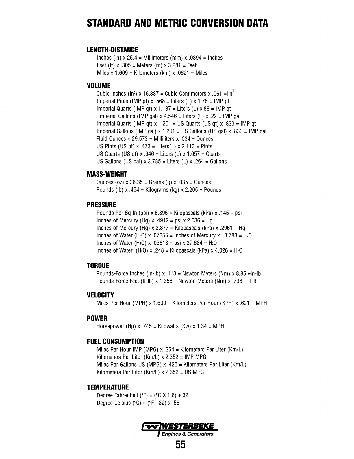
STANDARD
AND
LENGTH-DISTANCE
Inches
(in) x 25.4 = Millimeters
Feet
(ft) x .305 = Meters
Miles x 1.609 = Kilometers
METRIC
(mm) x .0394 = Inches
(m) x 3.281 = Feet
(km) x .0621 = Miles
CONVERSION
DATA
VOLUME
Cubic
Inches
(in3) x 16.387 = Cubic
Imperial
Imperial
Imperial
Imperial
Imperial
Fluid
US
US
US
Pints
(IMP
Quarts
Gallons
Quarts
Gallons
Ounces x 29.573 = Milliliters x .034 = Ounces
Pints
(US
pt) x .473 = Liters(L) x 2.113 = Pints
Quarts
(US
qt) x .946 = Liters
Gallons
(US
MASS-WEIGHT
Ounces
Pounds
(oz) x 28.35 = Grams
(Ib) x .454 = Kilograms
PRESSURE
Pounds
Inches
Inches
Inches
Inches
Inches
Per
of
Mercury
of
Mercury
of
Water
of
Water
of
Water
Sq
In
Centimeters x .061
pt) x .568 = Liters
(IMP
qt) x 1.137 = Liters
(IMP
gal) x 4.546 = Liters
(IMP
qt) x 1.201 = US
(IMP
gal) x 1.201 = US
gal) x 3.785 = Liters
(g) x .035 = Ounces
(psi) x 6.895 = Kilopascals
(Hg) x .4912 = psi x 2.036 = Hg
(Hg) x 3.377 = Kilopascals
(H20) x .07355 = Inches
(H20) x .03613 = psi x 27.684 = H20
(H20) x .248 = Kilopascals
(L) x 1.76 = IMP
(L)
x.88 = IMP
(L) x .22 = IMP
Quarts
(US
qt) x .833 = IMP
Gallons
(L) x 1.057 = Quarts
(L) x .264 = Gallons
(kg) x 2.205 = Pounds
(US
(kPa) x .145 = psi
(kPa) x .2961 = Hg
of
Mercury x 13.783 = H20
(kPa) x 4.026 = H20
3
=i
n
pt
qt
gal
qt
gal) x .833 = IMP
gal
TORQUE
Pounds-Force
Pounds-Force
Inches
Feet
VELOCITY
Miles
Per
Hour
(MPH) x 1.609 = Kilometers
POWER
Horsepower
FUEL
CONSUMPTION
Miles
Kilometers
Miles
Kilometers
(Hp) x .745 = Kilowatts
Per
Hour
IMP
Per
Liter
Per
Gallons
Per
Liter
TEMPERATURE
Degree
Degree
Fahrenheit
Celsius
(0C)
(in-Ib) x .113 = Newton
(ft-Ib) x 1.356 = Newton
(Kw) x 1.34 = MPH
(MPG) x .354 = Kilometers
(Km/L) x 2.352 = IMP
US
(MPG) x .425 = Kilometers
(Km/L) x 2.352 = US
(OF) = (OC X 1.8) + 32
=
(OF -32) x .56
Engines & Generators
MPG
Meters
Meters
Per
Per
MPG
(Nm) x 8.85
(Nm) x .738 = ft-Ib
Hour
(KPH) x .621 = MPH
Liter
(Km/L)
Per
Liter
(Km/L)
=in-Ib
55
Page 62

SUGGESTED
WESTERBEKE
SPARE
MARINE
PARTS
DIESEL
ENGINES
CONTACT
RAW
WATER
IMPELLER/GASKET
YOUR
PUMP
"","-.",,'~!"'"
WESTERBEKE
DEALER
FOR
SUGGESTIONS
AND
ADDITIONAL
INFORMATION
HARDWARE
KIT
FUEL
LIFT
PUMP
WESTERBEKE also offers two Spare Parts Kits,
each packaged in a rugged hinged toolbox.
Kit
"A"
includes the basic spares.
Kit
"B"
is for more extensive off-shore cruising.
A
Kit
Impeller Kit
Heat Exchanger Gasket
Fuel Filter with Gasket
Oil Filter
Drive Belt
Zinc Anodes
WESTERBEKE
ENGINE
AND A GALLON
RECOMMENDS
OIL
(YOUR
SPARE
I
"'fIV'/WESTERBEKE
I
BRAND)
OF
PREMIXED
EnaitJes
~~
FOR
PARTS
& Generators
WATER
CARRYING
AN
OIL
COOLANT.
KITS
56'
SEPERATOR
ENOUGH
CHANGE
(5
SPARE
OTS.)
AIR
INTAKE
FILTER
B
Kit
Impeller Kit
Water Pump Repair Kit
Thermostat Kit
Zinc Anodes
Complete Gasket Kit
Heat Exchanger Gasket
Injector
Fuel Filter with Gasket
Oil Filter
Drive Belt
FILTER
Page 63
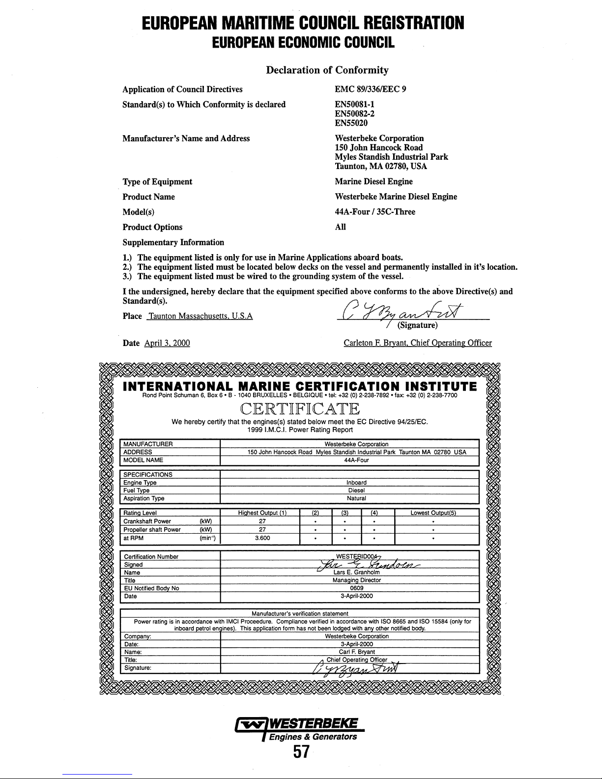
EUROPEAN
MARITIME
COUNCIL
REGISTRATION
EUROPEAN ECONOMIC
COUNCIL
Declaration of Conformity
Application
of
Council Directives
Standard(s) to Which Conformity is declared
and
Manufacturer's Name
of
Type
Equipment
Address
Product Name
ModeI(s)
Product
Options
Supplementary Information
1.) The equipment listed
is
only for use in Marine Applications aboard boats.
2.) The equipment listed must be located below decks on the vessel and permanently installed in it's location.
3.) The equipment listed must be wired to the grounding system of the vessel.
that
I the undersigned, hereby declare
the equipment specified above conforms to the above Directive(s) and
Standard(s).
Place Taunton Massachusetts. U.S.A
EMC
89/336IEEC
9
EN50081-1
EN50082-2
EN55020
Westerbeke Corporation
150
John
Myles Standish Industrial
Taunton, MA 02780,
Hancock Road
Park
USA
Marine Diesel Engine
Westerbeke Marine Diesel Engine
44A-Four I 35C-Three
All
/?
~
~
_
~
(Signature)
/
\/-
Date April
INTERNATIONAL
I
MANUFACTURER
I
ADDRESS
MODEL
SPECIFICATIONS
Engine
Fuel
Aspiration
Rating
Crankshaft Power
Propeller shaft
at
RPM
CertHication
Signed
Name
Title
EU
NotHied
Date
Power
Company:
Date:.
Name:
Title:
Signature:
Rond
Type
Tvpe
Level
NAME
Type
Body
rating
3.
Point
We
Power
Number
No
is
2000
Schuman
in
inboard
6,
Box
6'
hereby certify that
I
I
(kW)
(kW)
(min")
accordance
petrol
en
with
ines).
Carleton
MARINE CERTIFICATION
B •
1040
BRUXELLES
• BELGIQUE'
tel:
+32
(0)
2-238-7892 • fax:
CERTiFiCATE
the
engines(s)
1999I.M.C.1. Power
150
Highest
3.600
Manufacturer's
IMCI
Proceedure.
This
application
John
Output
27
27
stated below
Hancock
1
verHication
Compliance
form
meet
the
EC
Rating
Report
Westerbeke
Road
Myles
Standish
2 3 4
·
Directive 94/25/EC.
Corporation
Industrial
44A-Four
Inboard
Diesel
Natural
· ·
· · · ·
· · · ·
WESTEBIDOOh
,~
-"7_
E.
Granholm
Director
0609
3-April-2000
with
Corporation
3-April-2000
Carl
F.
Brvant
/7.
C/
..-'
J.r?~
with
any other
~
has
t-/
verHied
not
been
/I
I/,
Lars
Manaaina
statement
in
accordance
lodaed
Westerbeke
Chief Operating Officer
v
F.
Bryant. Chief Operating Officer
INSTITUTE
+32
(0)
2-238-noo
Park
Taunton
MA
02780
USA
Lowest
Output 5
·
.;-
ISO
8665
and
ISO
15584
(only
not
Hied
body.
for
I
I
I
Engines & Generators
57
Page 64

EUROPEAN
MARITIME
COUNCIL
REGISTRATION
INTERNATIONAL
Rond
Point
Schuman
I
I
MANUFACTURER
ADDRESS
I
I
MODEL
SPECIFICATIONS
EnaineType
Fuel
Aspiration
Ratina
Crankshaft Power
Propeller shaft Power
at
litle
Type
Level
RPM
CertHication
Signed
Name
EU
Not
Date
Power
Company:
Date:
Name:
litle:
Signature:
NAME
Type
Hied
Number
Body
rating
We
No
is
in
inboard
~
EUROPEAN ECONOMIC
MARINE CERTIFICATION
6 - B - t040
BRUXELLES -BELGIQUE
CERTKFKCATE
the
,
with
en
I
I
I
IMCI
lines).
engines(s)
19991.M.C.1.
150
Hiahest
3.600
This
application
John
Output
21
20
stated
Power
Hancock
1
;
form
Road
verHication
has
hereby
jkW)
petrol
6,
Box
certify that
(kW)
(min")
COUNCIL
-tel:
+32
{OJ
2-238-7892 -fax:
below
meet
the
EC
Rating
Report
Westerbeke
Myles
Standish
jgL
· · · ·
·
Directive
Corporation
Industrial
3SC-Three
Inboard
Diesel
Natural
(3)
J4)
· ·
INSTITUTE
+32
94/25/EC.
Park
Taunton
Lowest
· · ·
I
verHied
not
/7
/./
WESTERIDO..Q.4
I
'-r.,/U
Lars
Managing
statement
in
been
lodged
Carl
•
Chief
'-;1YYA.
.!::.
~,
."
7-
E.
Granholm
Director
0609
3-April-2000
I
wijh
with
any
other
F.
Bryant
Operatina Officer
or
.'-.
ISO
8665
notHied
and
body.
(OJ
2-238-7700
MA
Output{S)
·
·
ISO
15584
~
02780
USA
(only
I
for
Engines & Generators
58
Page 65

Engines & Generators
 Loading...