

Page 1

MULT I - P ORT S I NGLE – PHASE
MARINE GASOLINE GENERATORS
OPERATORS MANUAL
7.5 MCGA or 5.0 MCGA 60 Hz
6.2 MCGA or 4.2 MCGA 50 Hz
PART NUMBER 056556 REVISION AUGUST 2018
Page 2

Operator Manual for Marine Gasoline Generators
pag e ii
CALIFORNIA
PROPOSITION 65 WARNING
Breathing gasoline or diesel engine exhaust exposes you to chemicals known to the State of California to cause cancer and birth
defects or other reproductive harm.
■
Always start and operate the engine in a well-ventilated area.
■
If in an enclosed area, vent the exhaust to the outside.
■
Do not modify or tamper with the exhaust system.
■
Do not idle the engine except as necessary.
For more information go to www.P65warnings.ca.gov
WARNING: Exhaust fumes contain carbon monoxide, an odorless, colorless, and POISONOUS gas that can cause
unconsciousness and death. Symptoms of carbon monoxide exposure can include:
■
Dizziness
■
Nausea
■
Headache
■
Weakness
■
Sleepiness
■
Throbbing in Temples
■
Muscular Twitching
■
Vomiting
■
Impaired Judgement
IF YOU OR ANYONE ELSE EXPERIENCES ANY OF THESE SYMPTOMS, SEEK FRESH AIR IMMEDIATELY. If symptoms
persist, seek medical attention. Shutdown the unit and do not restart until it has been inspected and repaired.
A WARNING DECAL is provided by Westerbeke and should be fixed to a bulkhead
near your engine or generator. Westerbeke also recommends installing CARBON
MONOXIDE DETECTORS in the living/sleeping quarters of your vessel. They are cost
affective and easily obtainable at your local marine store.
©2018 Westerbeke, Inc. All Rights Reserved.
This document may not be reproduced or distributed in any form or by any means, graphic, electronic, or mechanical, including but not
limited to photocopying, scanning, recording, taping, e-mailing, or storing in information storage and retrieval systems without the written
permission of Westerbeke. Products that are referenced in this document may be trademarks and/or registered trademarks of their
respective owners. Westerbeke makes no claim to these trademarks. While every precaution has been taken in the preparation of this
document, individually, as a series, in whole, or in part, Westerbeke, the publisher, editor, and other contributors assume no responsibility
for errors or omissions, including any damages resulting from the express or implied application of information contained in this document
or from the use of other products, services, recommendations, or policies that may accompany it. In no event shall Westerbeke, publishers,
authors, or editors of this guide be liable for any loss of profit or any other commercial damage caused or alleged to have been caused
directly or indirectly by this document.
Page 3

Operator Manual for Marine Gasoline Generators
pag e iii
WARNING: Gasoline with an ETHANOL content
rating higher than 10% (E-10) is not allowed and
may void warranty. Read the precautions below
from E-10 Service Bulletin #251 issued by
Westerbeke Corporation.
Since 1990, the U.S. government has mandated the use of oxygenated
fuels to reduce carbon emissions into the atmosphere. Congress had
previously mandated the use of MTBE (methyl tertiary butyl ether) as this
oxygenate. This legislation expired in May 2006 because MTBE is a known
carcinogen and is also a ground water contaminant. Since then, in new
energy legislation, Congress mandated the use of ethanol as the
oxygenate. Ethanol, an alcohol-based fuel produced from corn is more
environmentally friendly.
About E-10
E-10 is a blend of 10% ethanol and 90% gasoline and is the mixture now
offered at most fuel stations. The use of E-10 in your car should have no
real effect on its operation. The use of E-10 in the marine marketplace,
however, will cause us to take some precautions.
Ethanol, being an alcohol-based product, is quite different from MTBE
which is an ether-based product. Ethanol is sort of a double-edged sword
when it comes to its ability to mix with water. E-10 can hold up to four
teaspoons of water per gallon but can hold only 0.15 teaspoons of water
per gallon when in solution. This is good, as it will allow your engine to
burn water that finds its way into your fuel tank up to this 4-teaspoon per
gallon limit. The problem comes when one gets beyond this limit.
As was the case with MTBE fuel, E-10 will also phase separate when it gets
beyond the saturation point. Phase separation occurs when the gasoline
and water are separated and the gasoline floats on top of the water. With
MTBE, one could simply pump the water out from under the fuel or let
the filters remove it and burn the gasoline left behind. MTBE reacts quite
differently with water than does ethanol. For this reason, the two fuel
blends should not be mixed when transitioning from MTBE to E-10.
(Note: The original bulletin was written in 2006. In 2018 and future years, mixing with
MTBE is no longer a primary concern since it is no longer available.)
Ethanol is a solvent and tends to clean any dirt or contaminants on
contact. For the consumer, this means that any dirt currently in the fuel
system will be mixed into solution and scrubbed out by the fuel filters.
This results in the need for the consumer to change fuel filters frequently.
The shelf life of E-10 is only 60-90 days. It will start to break down over
time and leave deposits in the fuel system. E-10 will also lose its volatility
very quickly. We recommend using a NON-ALCOHOL based fuel
stabilizer in your fuel all the time. The reason we are recommending a
non-alcohol-based stabilizer is to avoid adding even more alcohol to the
fuel. There are several good petroleum-based products on the market.
Another characteristic of E-10 is its ability to absorb water directly from
the atmosphere through the open vent system of your boat tank. In just
100 days at 70% humidity, E-10 can absorb enough water to reach its
phase separation point. To avoid this from occurring, use up the fuel as
quickly as you can. Try to plan on turning the fuel over as quickly as
possible by running the tank low before any extended periods of nonuse. Then fill up just before the next trip out. Avoid having E-10 fuel sit
unused in the tank for an extended period.
E-10 Precautions
Do not mix MTBE fuel with E-10 fuel.
Keep water out of your fuel tank.
Run a non-alcohol-based fuel stabilizer additive at all times.
The more you use your boat the less likely you are to have problems.
Don't leave large loads of fuel in the boat for lengthy periods of time.
There are approximately 5 to 8 percent fewer BTUs in E-10 (less
power per gallon).
Have a good water-separating fuel filter installed if you don't already
have one.
Keep several spare filters on board. You should also have a kit in a
sealable bucket that will seal up old filters and gas for safety and the
correct tools to change your filter. E-10 fuel will clean your fuel system
and consequently will often clog filters after changing.
Be aware of potential points of water intrusion into fuel tanks. Check
deck fill cap O-rings and fuel vents.
Ask your fuel supply source or marina about the ethanol content of
their fuel.
Check and, if necessary, replace rubber fuel lines.
Check and clean carburetors on older models.
Damage caused by contamination from water, foreign particles,
sludge, or gums entering or forming in the engine or fuel system is
not covered by the Westerbeke Corporation limited warranty.
Page 4

Operators Manual for Gasoline Generators 1 Important Safety Information
pag e iv
C O N T E N T S
1 Important Safety Information 1
2 Introduction 4
2.1 Quick Start Operators Guide ..................................................................................................................... 4
2.2 Documentation ......................................................................................................................................... 4
2.3 Parts Diagram ........................................................................................................................................... 5
2.4 Warranty Procedures ................................................................................................................................ 6
2.5 Conventions Used in this Manual ............................................................................................................. 7
2.6 Manuals and Software .............................................................................................................................. 7
2.7 Checklist: Protecting Your Investment ...................................................................................................... 7
2.8 Gasoline Engines ....................................................................................................................................... 7
2.9 Amperage Drain ....................................................................................................................................... 8
2.10 Ordering Parts .......................................................................................................................................... 8
2.11 Spare Parts, Kits, and Accessories ............................................................................................................. 8
3 Installation 10
3.1 Codes and Regulations............................................................................................................................ 10
3.2 Carbon Monoxide Detector .................................................................................................................... 10
3.3 Siphon-Break Requirements ................................................................................................................... 10
3.4 Exhaust System Requirements................................................................................................................ 11
3.5 How to Install a Remote Oil Filter ........................................................................................................... 11
4 Startup and Basic Operation 13
4.1 Fuel Source ............................................................................................................................................. 13
4.2 Fuel Supply Components ........................................................................................................................ 13
4.3 Engine Oil ............................................................................................................................................... 13
4.4 Engine Coolant........................................................................................................................................ 13
4.5 Coolant Recovery Tank ........................................................................................................................... 14
4.6 How to Bleed the Fuel System ................................................................................................................ 14
4.7 How to Start and Stop the Generator ..................................................................................................... 15
4.8 Safety Shutdown Switches and LEDs ....................................................................................................... 17
4.9 Break-In Procedure for Daily Operation .................................................................................................. 19
4.10 Checklist: Initial Startup .......................................................................................................................... 19
4.11 Checklist: Daily Startup ........................................................................................................................... 20
5 Maintenance 21
5.1 Maintenance Schedule ........................................................................................................................... 21
5.2 Maintenance: Fuel System ...................................................................................................................... 23
5.3 Maintenance: Cooling System ................................................................................................................ 25
5.4 Maintenance: Engine .............................................................................................................................. 28
5.5 Maintenance: Connections, Motors, and Circuit Breakers ...................................................................... 32
6 Diagnostics and Troubleshooting 36
6.1 Diagnostics Software for Microsoft Windows ......................................................................................... 36
6.2 Engine Troubleshooting .......................................................................................................................... 37
7 Wiring Diagrams 38
7.1
Remote Start/Stop Panels
............................................................................................................. 38
Page 5

Operators Manual for Gasoline Generators 1 Important Safety Information
pag e v
8 Lay-Up and Recommissioning 39
8.1 Lay-Up Prep: Lubrication System ............................................................................................................ 39
8.2 Lay-Up Prep: Intake Manifold ................................................................................................................. 39
8.3 Lay-Up Prep: Cylinder Lubrication ........................................................................................................... 39
8.4 Lay-Up Prep: Fuel System........................................................................................................................ 39
8.5 Lay-Up Prep: Starter Motor ..................................................................................................................... 39
8.6 Lay-Up Prep: Raw Water Cooling Circuit ................................................................................................. 40
8.7 Lay-Up Prep: Batteries ............................................................................................................................ 40
8.8 Lay-Up Prep: Spare Parts......................................................................................................................... 40
8.9 How to Recommission After a Lay-Up ..................................................................................................... 40
9 Generator Specifications 41
9.1 Specifications: Engine ............................................................................................................................. 41
9.2 Specifications: Fuel System ..................................................................................................................... 41
9.3 Specifications: Electrical System ............................................................................................................. 41
9.4 Specifications: Air Requirements ............................................................................................................ 41
9.5 Specifications: Cooling System ................................................................................................................ 42
9.6 Specifications: Lubrication System .......................................................................................................... 42
9.7 Specifications: AC Generator (Single Phase) ............................................................................................ 42
9.8 Specifications: Ignition System ............................................................................................................... 42
9.9 Specifications: Engine Component Tightening Torque ............................................................................ 43
Page 6

1 Operators Manual for Gasoline Generators
page vi
L I S T O F F I G U R E S
Figure 1: Parts Diagram ........................................................................................................................................ 5
Figure 2: Customer Identification Card ................................................................................................................. 6
Figure 3: Product Serial Number, Model Number, and Other Specifications ......................................................... 6
Figure 4: Spare Parts Kit........................................................................................................................................ 8
Figure 5: Suggested Spare Parts ............................................................................................................................ 9
Figure 6: Siphon-Break (Anti-Siphon Valve) with Stainless Steel Loop ................................................................ 10
Figure 7: Remote Oil Filter (Detailed View) ......................................................................................................... 11
Figure 8: Remote Oil Filter (After Installation) .................................................................................................... 12
Figure 9: Engine Coolant Recovery Tank ............................................................................................................. 14
Figure 10: Fuel System ........................................................................................................................................ 15
Figure 11: Control Panel DC Circuit Breaker and Start/Stop Switch .................................................................... 16
Figure 12: Remote Start/Stop Panels .................................................................................................................. 16
Figure 13: Exhaust Temperature Switch ............................................................................................................. 18
Figure 14: Coolant Temperature Sensor ............................................................................................................. 18
Figure 15: Control Panel DC Circuit Breaker ........................................................................................................ 18
Figure 16: Engine Oil and Coolant System Components ...................................................................................... 20
Figure 17: Fuel System Components ................................................................................................................... 23
Figure 18: Harness Lift Pump DC Auxiliary Power Adapter (Part Number 056264) .............................................. 24
Figure 19: Cooling System Heat Exchanger (Left) and Thermostat (Right) ........................................................... 26
Figure 20: Engine Oil Drain Hose (Left) and Oil Filter Assembly (Right) ............................................................... 28
Figure 21: Engine Oil Sump ................................................................................................................................. 29
Figure 22: Spark Plug .......................................................................................................................................... 29
Figure 23: Air Screen/Flame Arrestor.................................................................................................................. 30
Figure 24: Engine Oil Filter, Oil Pressure Sender, and Oil Pressure Switch .......................................................... 30
Figure 25: Battery Charger and 30A Fuse ............................................................................................................ 31
Figure 26: Catalyst Installation ........................................................................................................................... 32
Figure 27: BC Generator AC Terminal Connections ............................................................................................. 34
Figure 28: Generator Windings Schematic Diagram ............................................................................................ 34
Figure 29: Shore Power Transfer Switch ............................................................................................................. 35
Figure 30: Shore Power Transfer Switch Configurations ..................................................................................... 35
Figure 31: Typical Diagnostic Software Kit (Control Box, Cable, and Other Components) ................................... 36
Figure 32: Wiring Diagram for Start/Stop Panel with Fault Display ..................................................................... 38
Figure 33: Wiring Diagram for Start/Stop Panel Rocker Switch Only .................................................................. 38
Page 7

Operator Manual for Gasoline Generators 1
pag e 1
1
Important Safety Information
Read this manual carefully. Most accidents are caused by failure to follow
fundamental rules and precautions. Know when dangerous conditions exist
and take the necessary precautions to protect yourself and other people,
machinery, and property. As the owner or operator, always observe the
following safety risks and advisories provided for your convenience. This
important safety information aligns with American Boat and Yacht Council
(ABYC) standards; however, safety risks are not limited to the following list
and the responsibility for the identification of potential and actual risks and
for compliance with all safety advisories, maintenance activities, and other
conditions belongs exclusively to you as the owner or operator.
WARNING: Review all safety information. Failure
to observe the risks, warnings, and required
actions can result in damage, injury, or death.
Risk of Electric Shock
Do not touch the high-voltage AC electrical connections while engine
is running, or when connected to shore power.
Do not operate this machinery without electrical enclosures and covers
in place.
Shut off electrical power before accessing electrical equipment.
Use insulated mats whenever working on electrical equipment.
Make sure your clothing and skin are dry, not damp (particularly shoes)
when handling electrical equipment.
Remove watches and jewelry before working on electrical equipment.
Risk of Accidental Start
Accidental starts can cause injury or death.
Turn off the DC breaker on the control panel or turn the battery selector
switch to off before servicing the engine.
Verify all covers, guards, and hatches are re-installed and all personnel
are clear of the engine before starting.
Risk of Burns
Do not touch hot engine parts or exhaust system components.
A running engine gets very hot!
WARNING: Steam burns can cause injury or death.
Monitor engine antifreeze coolant level at the plastic coolant recovery
tank and periodically at the filler cap location on the water jacketed
exhaust manifold, but only when the engine is COLD.
In case of an engine overheat, allow the engine to cool before touching
the engine or checking the coolant.
Burns may also result from fires or explosions.
Risk of Fire
Fires can cause injury or death.
Gasoline and diesel fuel spills or vapors can ignite in a flash fire.
Do not smoke or permit flames or sparks to occur near the fuel system,
carburetor, fuel line, filter, fuel pump, while bleeding the fuel system or
other potential sources of spilled fuel or fuel vapors.
Use a suitable container to catch all fuel when removing the fuel line,
carburetor, or fuel filters.
Keep the compartment and the engine/generator clean and free of
debris to minimize the chances of fire. Wipe up all spilled fuel and
engine oil.
Do not operate with the air cleaner/silencer removed. Backfire can
cause severe injury or death.
Risk of Explosion
Explosions from fuel vapors can cause injury or death.
Follow re-fueling safety instructions. Keep the vessel hatches closed
when fueling. Open and ventilate cabin after fueling. Check below for
fumes or vapor before running the blower. Run the blower for four
minutes before starting your engine.
All fuel vapors are highly explosive. Use extreme care when handling
and storing fuels. Store fuel in a well-ventilated area away from sparkproducing equipment and out of the reach of children.
Do not fill the fuel tank(s) while the engine is running.
Shut off the fuel service valve at the engine when servicing the fuel
system. Take care in catching any fuel that might spill. Do not allow any
smoking, open flames, or other sources of fire near the fuel system or
engine when servicing. Ensure proper ventilation exists when servicing
the fuel system.
Do not alter or modify the fuel system.
Be sure all fuel supplies have a positive shut-off valve.
Be certain fuel line fittings are adequately tightened and free of leaks.
Make sure a fire extinguisher is installed nearby and is properly
maintained. Be familiar with its proper use. Extinguishers rated ABC by
the NFPA are appropriate for all applications encountered in this
environment.
Risk of Battery Explosion or Battery Acid Burns
Battery explosions can cause Injury or death.
Do not smoke or allow an open flame near the battery being serviced.
Lead acid batteries emit highly explosive hydrogen gas, which can be
ignited by electrical arcing or lit tobacco products. Shut off all electrical
equipment in the vicinity to prevent electrical arcs during servicing.
Never connect the (-) negative battery cable to the (+) positive
connection terminal of the starter solenoid.
Do not test the battery condition by shorting the terminals together.
Sparks could ignite battery gases or fuel vapors.
Ventilate any compartment containing batteries to prevent
accumulation of explosive gases.
To avoid sparks, do not disturb the battery charger connections while
the battery is charging.
Avoid contacting the terminals with body parts, tools, and other objects
to prevent burns or sparks that could cause an explosion. Remove
wristwatches, rings, jewelry, and other personal devices before handling
the battery.
Turn the battery charger off before disconnecting the battery
connections. Remove the (-) negative lead first and reconnect it last
when servicing the battery.
Sulfuric acid in batteries can cause severe injury or death.
Batteries contain corrosive sulfuric acid, which may splash on the skin
or into the eyes inadvertently when removing electrolyte caps.
When servicing the battery, or checking the electrolyte level, wear
rubber gloves, a rubber apron, and eye protection. If acid contacts skin
or eyes, wash it off at once with water.
Risk of Exposure to Toxic Exhaust Fumes and Gases
Carbon monoxide (CO) is an invisible, odorless, and deadly gas.
Inhalation produces flu-like symptoms, nausea, and even death.
Symptoms of carbon monoxide inhalation or poisoning include
vomiting, dizziness, headache, inability to think coherently, throbbing in
temples, muscular twitching, nausea, weakness, and fatigue.
Ensure that the exhaust system is adequate to expel gases discharged
from the engine. Check the exhaust system regularly for leaks and make
sure the exhaust manifold/water-injected elbow is securely attached.
Be sure the unit and its surroundings are well ventilated. Run blowers
when running the generator set or engine.
Do not run the generator set or engine unless the boat is equipped with
a functioning marine carbon monoxide detector that complies with
ABYC A-24. Consult your boat builder or dealer for installation of
approved detectors. For additional information, refer to educational
information about carbon monoxide in ABYC TH-22.
Do not use copper tubing in diesel exhaust systems. Diesel fumes can
rapidly destroy copper tubing in exhaust systems. Exhaust sulfur causes
rapid deterioration of copper tubing resulting in exhaust/water leakage.
Do not install exhaust outlet where exhaust can be drawn through
portholes, vents, or air conditioners. If the engine exhaust discharge
outlet is near the waterline, water could enter the exhaust discharge
outlet and close or restrict the flow of exhaust.
Avoid overloading the craft.
Risk of Injury from Moving Parts
Rotating parts can cause injury or death.
Do not service the engine while it is running. If a situation arises in which
it is necessary to make operating adjustments, use extreme care to
avoid touching moving parts and hot exhaust system components.
Page 8

1 Operator Manual for Gasoline Generators
page 2
Do not wear loose clothing or jewelry when servicing equipment; tie
back long hair and avoid wearing loose jackets, shirts, sleeves, rings,
necklaces or bracelets that could be caught in moving parts.
Do not work on machinery when you are mentally or physically
incapacitated by fatigue.
Make sure all attaching hardware is properly tightened.
Always keep protective shields and guards in their respective places.
Do not check fluid levels or drive belt tension while engine is running.
Do not allow swimming or other activity near the exhaust discharge
opening for the generator while the generator is operating. Carbon
monoxide poisoning or death can occur.
Noise Hazard
High noise levels can cause hearing loss.
Never operate an engine without its muffler installed.
Do not run the engine with the air intake (silencer) or flame arrestor
removed.
Do not run engines for long periods with their enclosures open (when
installed).
Safety Standards for Gasoline Engines and Generators
Many standard safety tips, notes, cautions, and warnings are repeated in
this manual to highlight critical information. Read all manuals carefully,
maintain your equipment, and follow all safety procedures.
Installing a gasoline engine or generator should begin with a thorough
examination of the American Boat and Yacht Council (ABYC) standards.
These standards are from a combination of sources including the USCG and
the NFPA. Applicable sections of the ABYC standards include:
H-2 Ventilation for Boats using Gasoline
H-24 Gasoline Fuel Systems
P-1 Installation of Exhaust Systems for Propulsion and Auxiliary Engines
P-4 Marine Inboard Engines and Transmissions
E-11 AC and DC Electrical Systems on Boats
Read the following ABYC, NFPA, and USCG publications, safety codes, and
standards. Follow their recommendations when installing all engines and
generators. All installations in the United States must comply with the Code
of Federal Regulations (CFR).
ABYC Standards and Technical Information Reports for Small Craft
American Boat and Yacht Council
613 Third Street, Suite 10
Annapolis, MD 21403
www.abycinc.org
NFPA Fire Protection Standard for Motor Craft
National Fire Protection Association
11 Tracy Drive
Avon Industrial Park
Avon, MA 02322
http://www.nfpa.org
United States Coast Guard (USCG) 33CFR183: Boats and Equipment
U.S. Government Printing Office
Washington, D.C. 20404
www.gpo.gov or www.ecfr.gov
Carbon Monoxide from CO/Low CO Generators
Carbon monoxide (CO) is a component of engine exhaust. It is a colorless,
tasteless, odorless, lighter than air poisonous gas that can kill you without
any warning. CO poisoning is one of the major safety risks associated with
boating. It is a threat that must not be underestimated. Westerbeke LowCO generators are designed to dramatically reduce normal levels of CO in
the engine exhaust. Several standards for CO have been published,
expressed in parts per million (ppm) and hours of exposure:
Table 1: Emissions Exposure Standards
Regulator
CO Level (ppm)
Max Exposure (Hours)
EPA 9 8.0
ACGIH
25
8.0
EPA
35
1.0
NIOSH
35
8.0
OSHA
50
8.0
ACGIH
125
0.5
NIOSH
200
0.0
NIOSH (IDLH)
1200
0.0
In the last row of the table, 1200 ppm is the so-called IDLH concentration:
Immediately Dangerous to Life and Health.
A city in California characterizes the effect of CO concentration this way:
25 ppm: Permissible exposure level, no apparent toxic symptoms.
100 ppm: No poisoning for long period. Allowable for several hours.
200 ppm: Should not be exposed above this level for any period of
time. A possible mild frontal headache in two to three hours.
Even though the generator normally produces very low levels of CO, an
untreated exhaust leak would be extremely dangerous. For this reason, it is
extremely important to install a CO detector near the generator and to be
sure it is always turned on and functioning properly. If this detector sounds,
do not turn it off, assuming it is a false signal.
You cannot taste, smell, or otherwise detect CO. Leave the detector on, turn
off all engines and generators, evacuate the boat leaving ports and hatches
open, and seek professional help.
As soon as CO leaves the exhaust outlet, the level is subject to dilution in
the open air. The closer a person is to the exhaust outlet, the higher the
concentration of CO.
In a closed space, such as the engine compartment, the boat, or underneath
a stem swim platform, concentrations will potentially rise to the undiluted
level emanating from the exhaust system due to a lack of fresh air to dilute
the exhaust gas. Therefore, one should never rely on dilution of the exhaust
to provide a margin of safety.
Westerbeke Low-CO generators achieve reduction of CO by precise control
of the engine air/fuel ratio coupled with after-treatment in a special catalyst.
CO emissions are not the same for every model because each engine is
different. Also, certain fuel system components are common across several
engine models being adequate for some and extra-adequate for others,
thus producing different CO levels for different models.
The fuel system which accomplishes the required precise air/fuel ratio
control is comprised of many different components: purchased subassemblies, machined castings, sensors, electronics and others. Because of
the extreme level of CO reduction, any variability in the functioning of any
these components can and will cause variability of the CO output.
CO concentration also varies with load. Usually, but not always, the worstcase CO concentration occurs at maximum load.
Inspection
The catalyst is critical for minimizing engine CO exhaust emissions. Any
water intrusion into the exhaust system can quickly compromise the proper
operation of the catalyst. Inspection of the catalyst at the prescribed
intervals is critically important.
Use a CO analyzer to check for the presence of CO while the engine is
running. See 5.4.9 Exhaust System Maintenance.
Westerbeke exhaust system installation instructions must be adhered to.
NOTE: Water intrusion is not a product defect and is not covered under
your Westerbeke product warranty or the emissions-specific warranty
mandated by various regulating authorities such as EPA and CARB.
Maintenance of fuel filters, air filters, and any other components affecting
the flow of air or the flow of fuel to the engine is critically important.
The catalyst must be replaced every 2,000 hours of engine operation:
Catalyst performance will degrade over time. As the generator accumulates
operating hours, CO concentrations will increase.
Verification of satisfactory CO levels must be done seasonally or every
250 hours (whichever occurs first): Verification involves actual sampling
of exhaust gas with an appropriate CO analyzer.
There are two locations where exhaust gas can be sampled:
Dry, but hot, exhaust can be sampled at the plugged tapped hole in the
exhaust elbow intended for back pressure measurements.
Measurements at this location may not be practical in all instances due
to the high exhaust temperature, temperature limits of the analyzer,
safety concerns over temperatures involved or the possibility of high
levels of CO.
The other location is the vessel exhaust outlet, which contains entrained
cooling water (except dry stack exhaust systems). Only analyzers with
probes should be used at this location and it is critical that the probe
not ingest water. Probe-type analyzers have an air pump drawing a gas
sample through the probe. They tend to ingest water when it is present.
Follow these tips:
Aim the probe downwards with the opening pointed in the direction of
the water flow and just out of the flow.
Page 9

Operator Manual for Gasoline Generators 2 Introduction
pag e 3
Position the analyzer as high as possible with the tubing leading to the
probe running continuously downhill.
Observe the usually translucent tubing between the probe and the
analyzer and be sure no water is ingested. If any water is ingested into
the analyzer, it must be repaired or replaced and recalibrated.
When measuring CO at the exhaust outlet be aware of the ambient CO
level by also measuring CO away from and upwind of the exhaust
outlet, especially in marinas. The CO level at the exhaust outlet will be
influenced upwards by the ambient level.
Whenever taking the time to verify proper CO concentration from the
exhaust with a CO analyzer, always use the analyzer to sniff around the
engine looking for CO from exhaust leaks. Pay close attention to the
connection of the cylinder head to the exhaust manifold, the exhaust
manifold to the water-injected exhaust elbow, and all subsequent
downstream exhaust components and hoses.
Exhaust gas that has not yet passed through the catalyst is raw,
untreated, and very high in CO content.
Analyzers usually require periodic calibration. Follow the instructions
that come with the analyzer very carefully regarding calibration.
The following manufacturers offer CO analyzers: Extech, TIF, Testo, TSI,
Bacharach, Fluke, Monoxor, Fyrite, Zellweger Analytics, Industrial
Scientific, GFG, TPI, Teledyne, and others.
Westerbeke recommends analyzers with a probe connected to the
analyzer by a length of transparent tubing. They are slightly more
expensive than those with the sensor built-in to one end of the analyzer,
but they allow you to sample the exhaust coming out of the boat
exhaust outlet.
California Exhaust Emissions Standards
This genset meets the requirements of the California Exhaust Emissions
Standards as stated on the nameplate. California users of this genset should
be aware that unauthorized modifications or replacement of fuel, exhaust,
air intake, or speed control system components that affect engine emissions
are prohibited. Unauthorized modification, removal or replacement of the
engine label is prohibited.
Federal Emissions Compliance Period
The Federal Emissions Compliance Period referred to on the nameplate
indicates the number of operating hours for which the engine has been
shown to meet Federal Emissions requirements:
Category A = 1000 hours
Category B = 500 hours
Category C = 250 hours
Carefully review operator, installation, and other manuals and
information you receive with your genset. If you are unsure whether
the installation, use, maintenance, or service of your genset is
authorized, seek assistance from an approved Westerbeke dealer.
California genset users may use the table below as an aid in locating
information related to the California Air Resources Board emissions control
requirements.
Table 2: Emissions Control Information
Emissions Warranty
Information
See the California emissions control
warranty statement in the same packet
of information as this manual when the
genset is shipped from the factory.
Engine Fuel
Requirements
The engine is certified to operate on
unleaded gasoline. See 9.2
Specifications: Fuel System.
Engine Lubricating
Oil Requirements
See 4.3 Engine Oil and 9.6
Specifications: Lubrication System.
Engine Adjustments
To learn more about the Electronic
Control Unit (ECU), see the Westerbeke
Service Manual for your product model.
Engine Emission
Control System
The engine emission control system
consists of engine design and precision
manufacturing.
Engine Valve
Adjustment
See 5.1: Maintenance Schedule.
Engine Ignition
Timing
Catalyst
Oxygen Sensor
Back Pressure
Page 10

2 Introduction Operator Manual for Gasoline Generators
page 4
2 Introduction
This Westerbeke generator is a product of our many years of experience and advanced technology. We take
great pride in the superior durability and dependable performance of our engines and generators. Thank you
for selecting Westerbeke.
To get the full use and benefit from your generator, it is important that you operate and maintain it correctly.
This manual is designed to help you do this. Please read this manual carefully and observe all the safety
precautions throughout. Should your generator require servicing, contact your nearest Westerbeke dealer.
2.1 Quick Start Operators Guide
To get started quickly, refer to these sections:
■
Important Safety Information
■
Parts Diagram
■
Checklist: Protecting Your Investment
■
Checklist: Initial Startup
■
Checklist: Daily Startup
■
Maintenance Schedule
■
Lay-Up and Recommissioning
WARNING: Carbon monoxide emissions can cause injury or death. Mount carbon monoxide detectors in all living
quarters on the vessel.
2.2 Documentation
■
This is your Operators Manual.
■
An Installation Manual and associated parts information are available online.
■
A Service Manual is also available online.
Visit www.westerbeke.com.
You can also order printed documentation from your local Westerbeke/Universal dealer. Fees and shipping
charges may apply
Page 11
Operator Manual for Gasoline Generators 2 Introduction
pag e 5
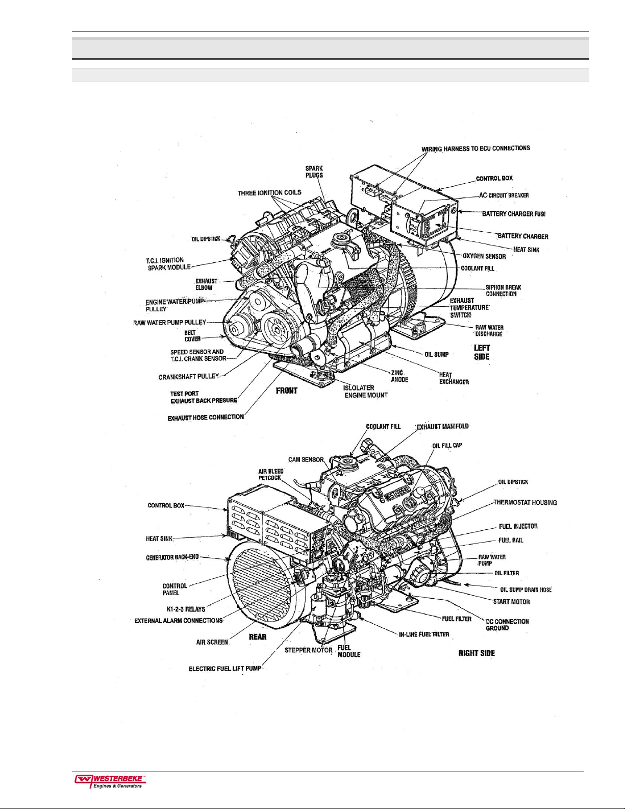
2.3 Parts Diagram
Figure 1: Parts Diagram
Page 12

2 Introduction Operator Manual for Gasoline Generators
page 6
2.4 Warranty Procedures
Your Westerbeke Warranty Statement is included in the product documentation package. Complete and return
the included warranty registration card or register your product online at www.westerbeke.com.
You should receive your customer warranty identification card in the mail within 30 days of registering. If you
do not, contact the factory and have your product model number, serial number, and in-service date available.
Figure 2: Customer Identification Card
Figure 3: Product Serial Number, Model Number, and Other Specifications
Page 13

Operator Manual for Gasoline Generators 2 Introduction
pag e 7
2.5 Conventions Used in this Manual
This manual includes safety information, operating procedures, maintenance schedules, and troubleshooting
tips. Information is sometimes highlighted when it meets the following criteria:
NOTE: An operating procedure essential to note.
TIP: A recommended best practice or suggestion.
CAUTION: Procedures, which can result in the damage or destruction of your engine if not properly followed.
WARNING: Procedures which can result in personal injury or death if not strictly observed.
2.6 Manuals and Software
Westerbeke frequently updates our manuals and software. For the latest information, consult your Westerbeke
representative or visit www.westerbeke.com.
The 5.0 or 7.5 MCGA Service Manual is available as a PDF download from www.westerbeke.com. This Service
Manual can also be purchased in hard copy from your Westerbeke dealer.
CAUTION: Technical information is provided in our documentation for your reference and convenience. Westerbeke
recommends that your engine, generator or climate control system is serviced and/or installed only by a qualified
Westerbeke distributor or dealer.
2.7 Checklist: Protecting Your Investment
Care at the factory during assembly and thorough testing have resulted in a Westerbeke generator capable of
many hours of dependable service. However, the manufacturer cannot control where the generator is installed
in the vessel or how well the unit is installed, operated, and serviced in the field. As the buyer or owneroperator, this responsibility is up to you.
To prolong the life of your generator, follow these important points:
Properly install, configure, and prepare your unit for safe operation.
Verify that you have an efficient well-designed exhaust system that includes an anti-siphon break to
prevent water from entering the engine.
Change the engine oil and filters, and maintain all engine and generator components, as directed in
Chapter 5.1: Maintenance Schedule.
Use clean, filtered unleaded fuel (maximum 10% ethanol).
Winterize your engine as directed in Chapter 8: Lay-Up and Recommissioning.
2.8 Gasoline Engines
In many ways, the gasoline engine driving an AC generator is like a gasoline automobile engine. The cylinders
are vertical in-line, and the engine cylinder head has an overhead camshaft which is belt driven. The engine
utilizes electronic ignition, no distributor. The engine incorporates a pressure type lubrication system and a
fresh water-cooled engine block, which is thermostatically controlled.
Page 14
2 Introduction Operator Manual for Gasoline Generators
page 8
To a large degree, the generator engine requires the same preventative maintenance that is required of a
gasoline automobile engine. The most important factors to prolong generator longevity are proper ventilation,
maintenance of the fuel system, ignition system, cooling system and the generator back-end.
2.9 Amperage Drain
Be aware of the following very important condition that will typically occur when you do not operate your
generator for an extended period.
CAUTION: A very small amount of amperage is being drawn from the starting battery by the electronics on the unit
when the generator is not in use. To prevent this very slow discharging of the starting battery, turn OFF either the panel
DC breaker or the starting battery switch when the unit will not be operated for an extended time.
2.10 Ordering Parts
Whenever replacement or service parts are needed, always provide the generator model number, engine serial
number, and generator serial number as they appear on the silver and black name plate located on the
generator end. You must provide us with this information, so we may properly identify your generator set.
Include a complete part description and part number for each part needed (see the separately furnished Parts
Catalog). Insist upon Westerbeke genuine parts because will fit or generic parts are frequently not made to the
same specifications as original equipment.
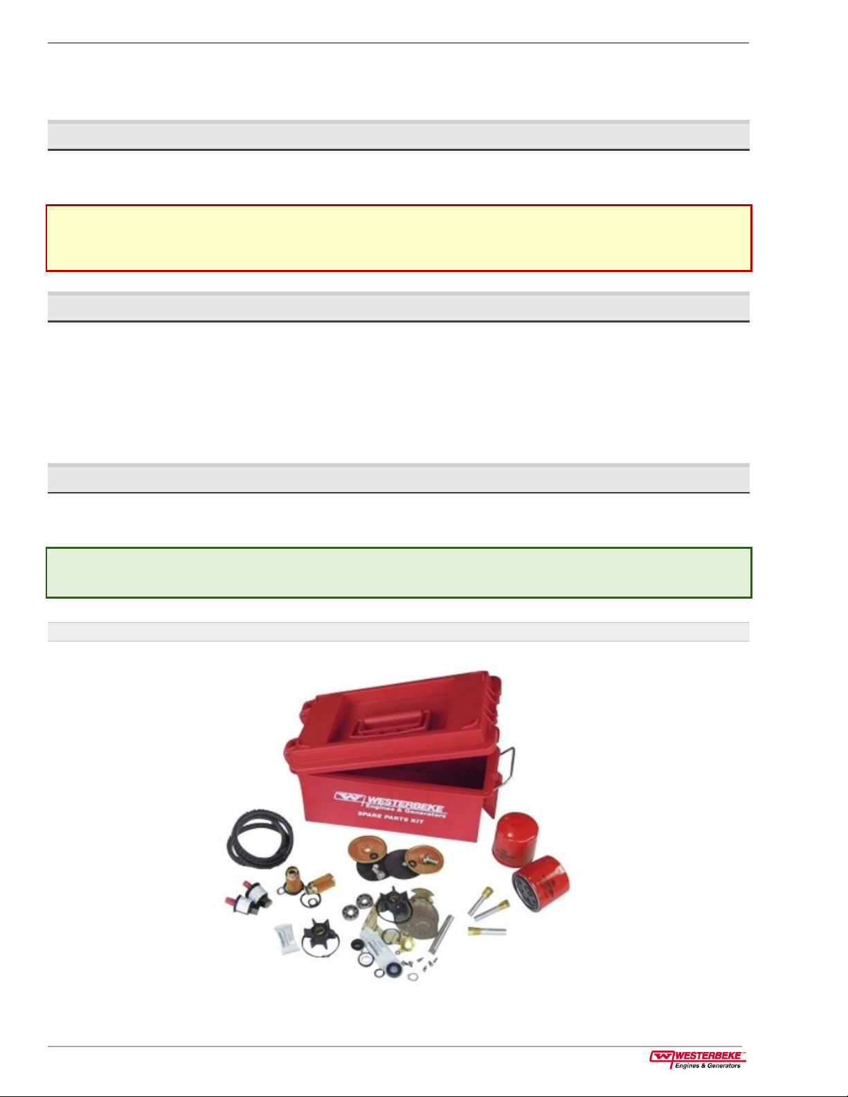
2.11 Spare Parts, Kits, and Accessories
Certain spare parts will be needed to support and maintain your Westerbeke generator. Your local Westerbeke
dealer will assist you in preparing an inventory of suggested spare parts and accessories.
TIP: We also recommend carrying enough spare engine oil for an oil change and one gallon of premixed coolant for the
cooling system.
Figure 4: Spare Parts Kit
Page 15

Operator Manual for Gasoline Generators 2 Introduction
pag e 9
For your convenience, we offer two spare part kits, each packaged in a water-tight storage case:
■
Kit A includes the basic set of the most essential recommended spare parts.
■
Kit B includes everything in Kit A, plus additional spare parts for more extensive off-shore cruising.
Spare Part List
Kit A
Kit B
Drive Belt
Fuel Filters
Heat Exchanger Gasket
Impeller Kit
Oil Filter
Spark Plugs
Zinc Anodes
Complete Gasket Kit
Thermostat Kit
Water Pump Repair Kit
Figure 5: Suggested Spare Parts
Page 16

3 Installation Operator Manual for Gasoline Generators
page 10
3 Installation
NOTE: When installing Westerbeke engines and generators, pay strict attention to all installation requirements.
In addition to the installation information in this chapter of this guide, also refer to the Marine Installation
Manual (publication #043268) supplied with your product. That installation guide covers engines and
generators and is included with each gasoline and diesel unit. A PDF is available to download from our website
at https://www.westerbeke.com/installation manuals/installation_manual.pdf.
3.1 Codes and Regulations
Strict federal regulations, ABYC guidelines, Coast Guard standards, and NFPA safety codes must be complied
with when installing engines and generators in a marine environment.
See Safety Standards for Gasoline Engines and Generators in Chapter 1: Important Safety Information.
3.2 Carbon Monoxide Detector
Westerbeke recommends mounting a carbon monoxide detector in all living quarters on the vessel.
The presence of carbon monoxide could indicate an exhaust leak from your engine or from the exhaust
elbow/hose of the exhaust system from another vessel.
WARNING: If carbon monoxide is present, ventilate the area with clean air and correct the problem immediately!
Carbon monoxide, even in small amounts, is deadly.
3.3 Siphon-Break Requirements
For installations where the exhaust manifold/water injected exhaust elbow is close to or will be below the
vessel waterline, provisions must be made to install a siphon-break in the raw water supply hose to the
exhaust elbow. This hose must be looped a minimum of 24.0 inches (61.0 cm) above the vessel waterline.
CAUTION: Failure to use a siphon-break when the exhaust manifold injection port is at or below the load waterline will
result in raw water damage to the engine and possible flooding of the boat.
If you have any doubt about the position of the water-injected exhaust elbow relative to the vessel waterline
under the various operating conditions for your vessel, install a siphon-break, available from Westerbeke or
your local authorized Westerbeke dealer.
Figure 6: Siphon-Break (Anti-Siphon Valve) with Stainless Steel Loop
Page 17

Operator Manual for Gasoline Generators 3 Installation
pag e 11
NOTE: A siphon-break requires periodic inspection and cleaning to ensure proper operation. Failure to properly
maintain a siphon-break can result in catastrophic engine damage. Consult the siphon-break manufacturer for proper
maintenance.
3.4 Exhaust System Requirements
To install exhaust system components, see the installation manual.
■
The system must be designed to prevent the entry of water into the exhaust system under any sea
conditions and at any angle of vessel heel.
■
The exhaust system hose must be certified for marine use.
TIP: Corrugated marine exhaust hose is recommended. The use of this type of hose allows for extreme bends and turns
without additional fittings and clamps. A single length of corrugated exhaust hose can often be used.
3.5 How to Install a Remote Oil Filter
The optional remote oil filter kit (part number 040078) is a popular accessory used to relocate the engine oil
filter from the engine to a more convenient location such as an engine room bulkhead. The remote oil filter
ships to you already fully assembled.
Note: The remote oil filter is not compatible with a Venclosure.
1.
Remove your previous engine oil filter. Follow the steps in 5.4.2 How to Replace the Engine Oil Filter.
2.
When installing this kit, apply a thin coat of clean oil to the O-ring and the filter gasket where the filter
contacts the base. Tighten firmly by hand.
3.
Thread on the optional Westerbeke remote oil filter kit. Always install this kit with the oil filter facing down.
4.
Hand-tighten an additional three-quarters (¾) turn after the O-ring contacts the base.
5.
Fasten securely to a bulkhead (screws are owner-supplied for best fit).
Figure 7: Remote Oil Filter (Detailed View)
Page 18

3 Installation Operator Manual for Gasoline Generators
page 12
CAUTION: Do not disturb the oil lines. If the oil flows in the reverse direction, the bypass valve in the filter assembly will
prevent the oil from reaching the engine, possibly causing internal engine failure. If there is no oil pressure reading, shut
down immediately and check the hose connections.
Figure 8: Remote Oil Filter (After Installation)
NOTE: Westerbeke is not responsible for engine failure due to the improper installation of the remote oil filter.
Page 19

Operator Manual for Gasoline Generators 4 Startup and Basic Operation
pag e 13
4 Startup and Basic Operation
4.1 Fuel Source
The fuel source for this model is gasoline. Use only clean properly filtered fuel!
CAUTION: Use unleaded 89 octane gasoline or higher. Ethanol gasoline must not exceed E-10 (10%). Gasoline with
higher ethanol content is not acceptable for use in this model and will void the warranty.
4.2 Fuel Supply Components
The fit and tolerance of some components in the fuel system are very critical. Dirt particles which might pass
through the filter can damage these finely finished parts. It is important to buy clean fuel, and to keep it clean.
The best fuel can be rendered unsatisfactory by careless handling or improper storage facilities.
Follow these suggestions:
■
Always provide clean and pure fuel in the tank for your engine.
■
Check the fuel supply frequently.
■
Purchase a well-known brand of fuel.
■
Install and regularly service a good, Coast Guard approved metal bowl type filter/water separator
between the fuel tank and the engine.
4.3 Engine Oil
Use a good brand of engine oil with API and SAE designations as listed in 9.6 Specifications: Lubrication
System. Change the engine oil and filter after the first 50 hours of engine break-in operation. Then follow the
oil and filter change intervals as specified in 5.1: Maintenance Schedule.
Westerbeke does not approve or disapprove the use of synthetic oils. If synthetic oils are used, engine break-in
must be performed using conventional oil. The required oil change intervals are listed in this manual and
cannot be extended, even if synthetic oils are used.
NOTE: The information above supersedes all previous statements regarding synthetic oil usage.
4.4 Engine Coolant
Westerbeke recommends a mixture of 50% antifreeze and 50% distilled water. Distilled water is free from the
chemicals and minerals that can corrode internal engine surfaces.
The antifreeze performs double duty. It allows the engine to run at proper temperatures by transferring heat
away from the engine to the coolant. It also lubricates and protects the cooling circuit from rust and corrosion.
Use a good quality antifreeze that contains supplemental cooling additives (SCAs) to keep the antifreeze
chemically balanced, crucial to long-term protection.
The distilled water and antifreeze should be pre-mixed before being poured into the cooling circuit.
TIP: Use the environmentally-friendly, long-lasting antifreeze that is now available. A proper 50/50 mixture as
recommended will protect the engine coolant at temperatures as low as -40° F.
Page 20

4 Startup and Basic Operation Operator Manual for Gasoline Generators
page 14
4.5 Coolant Recovery Tank
A coolant recovery tank kit is supplied with each generator to allow for engine coolant expansion and
contraction during engine operation without the loss of coolant and without introducing air into the cooling
system. This tank is best located at or above the level of the engine exhaust manifold.
Figure 9: Engine Coolant Recovery Tank
4.6 How to Bleed the Fuel System
The initial setup of the generator requires that you or your mechanic bleed the air from the fuel system. This
procedure, known as priming or bleeding the fuel system, is also required whenever the fuel filters are serviced.
1.
Disconnect the fuel module from the engine wiring harness.
2.
Attach your fuel pressure gauge set (Snap On #MT337B, OTC 7211) or equivalent to the Schrader valve on
the fuel module. Direct the bleed hose from the pressure gauge into a proper container.
3.
Open the bleed valve on the pressure gauge, press the STOP switch, and hold it depressed. This activates the
low-pressure fuel pump.
4.
Observe the fuel flow through the bleed hose. When no air bubbles are seen, release the STOP switch to
close the bleed valve and observe the fuel pressure (typically about 3-5 psi).
5.
Remove the pressure gauge from the fuel module and connect it to the Schrader valve on the fuel rail.
6.
Re-connect the fuel module to the engine harness.
7.
Open the bleed valve on the fuel pressure gauge. Press the STOP switch and hold it depressed. This activates
both the low-pressure and high-pressure fuel pumps. Observe the fuel flow through the bleed hose and
when no air bubbles are seen, close the bleed valve and observe the fuel pressure. The pressure should be in
the 40-psi range.
8.
Remove the pressure gauge set and replace the caps on the two Schrader valves.
9.
Insure that all harness connections are secure, operate the generator and check that there are no fuel leaks.
WARNING: The fuel is under extreme pressure! Do not allow any smoking or open flames in the area! Clean up spilled
fuel and properly discard any used cloths, rags, and towels.
Page 21

Operator Manual for Gasoline Generators 4 Startup and Basic Operation
pag e 15
Figure 10: Fuel System
4.7 How to Start and Stop the Generator
4.7.1 How to Start and Stop the Generator (Control Panel)
The start/stop rocker switch is the only functional component on the generator control panel (and optional
remote control panel) used to start and stop the generator. The start/stop rocker switch is a three-position
switch with momentary contacts in the START and STOP positions and a stationary contact in the NORMAL
center position. This position allows the generator to run once started and enables one or more remote
start/stop panels to control the start/stop functions of the generator.
1.
To start the unit turn the DC circuit breaker on, press the rocker switch to the
START
position and release it.
2.
The switch returns to its center position. The engine starts. A
green
LED on the switch indicates the engine is
running.
NOTE: There is a delay of a few seconds while the ECU self-tests run before the start switch responds.
3.
To stop the unit, press the rocker switch to the
STOP
position and release it. The
STOP
position stops the
engine in normal operation as well as in an emergency.
NOTE: This position is also used to prime the fuel system when necessary. See 4.6 How to Bleed the Fuel System.
4.
The
green
LED goes out indicating the engine has shut down.
Page 22

4 Startup and Basic Operation Operator Manual for Gasoline Generators
page 16
Figure 11: Control Panel DC Circuit Breaker and Start/Stop Switch
4.7.2 How to Start and Stop the Generator (Remote Control Panel)
You can also perform the same steps using an optional remote control panel. Two remote start/stop panels are
available that allow for the engine/generator to be controlled from any location on the boat.
The remote panels connect to the main panel using a 15-foot or 30-foot wiring harness. You can combine
them to form a 45-foot length. To connect a remote panel, refer to the Wiring Diagram section of this manual.
Once installed, the engine/generator can be started and stopped from either the remote or the main panel.
4.7.3 Remote Start/Stop Panel (With LED Fault Display)
The components on this panel include:
■
A three-position start/stop rocker switch.
■
A green LED run indicator light on the rocker switch.
■
A four-position LED fault shutdown display.
The start/stop rocker switch functions the same as the start/stop rocker switch on the generator control panel
as previously explained.
The green LED run indicator light on the rocker switch is illuminated whenever DC power is ON. It will go dim
as the engine cranks and will brighten as the engine starts, indicating the generator is running.
Figure 12: Remote Start/Stop Panels
Page 23
Operator Manual for Gasoline Generators 4 Startup and Basic Operation
pag e 17
4.7.4 Failure to Start
The start cycle will automatically terminate after 6-8 seconds of cranking. Three crank cycles can be attempted
before the ECU initiates a SPEED fault and prevents further crank cycle attempts. Investigate the cause of this
no-start, correct it, and reset the power to the ECU.
CAUTION: Prolonged cranking can result in the exhaust filling with water and possible backflow into the engine. This
could cause catastrophic damage to your generator/engine.
4.8 Safety Shutdown Switches and LEDs
The engine/generator is protected by switches and sensors that send signals to the ECU that it interprets as a
fault and automatically shuts down the generator engine. When an automatic shutdown occurs, one or two of
the control panel fault LED lights will illuminate indicating what fault caused the engine to shut down. To
correct the fault, see 6.2 Engine Troubleshooting.
NOTE: Do not attempt to re-start the generator before correcting the fault.
The LED fault shutdown display includes the following six LED light combinations that indicate to the operator
the cause of the engine automatic shutdown:
■
CHECK ENGINE
■
OIL PRESSURE
■
ENGINE TEMPERATURE
■
EXTERNAL ALARM
■
EXHAUST TEMPERATURE
■
SPEED (flashes)
The SPEED indicator flashes to indicate underspeed conditions and remains steady for overspeed.
If the generator shuts down from one of these faults, the fault LED remains illuminated. To reset the LED, the
DC breaker on the control box must be turned OFF and then back ON.
NOTE: The CHECK ENGINE light indicates a possible emissions control problem. Immediate action should be taken to
troubleshoot and correct this problem.
The EXT ALARM light indicates a fault with the fire suppression circuit. Troubleshoot the circuit to determine
the fault (the fire suppression circuit must be a closed when the circuit is active).
The 8-amp fuse protects the control panel from high amperage or short circuit condition.
The 15-amp DC circuit breaker protects the K1, K2, and K3 relays (closed circuit) from a high-amperage or
short-circuit condition.
4.8.1 Speed Sensor (Hall Effect)
A speed sensor is mounted on a bracket adjacent to the front crankshaft pulley. This sensor monitors pulley
rotation and sends a voltage signal to the ECU that interprets it as crankshaft speed.
■
If both speed LEDs are flashing, it indicates underspeed.
■
If both speed LEDs are illuminated (not flashing), it indicates overspeed.
■
If a speed threshold is reached, either overspeed or underspeed, the ECU shuts the unit down.
4.8.2 Oil Pressure Switch and Sender
An oil pressure switch is located on the right side of the oil filter mounting bracket. See Figure 24: Engine Oil
Filter, Oil Pressure Sender, and Oil Pressure Switch.
Page 24

4 Startup and Basic Operation Operator Manual for Gasoline Generators
page 18
This is a normally open contact switch. It functions with the time relay circuit to ensure DC voltage to the fuel
pump circuit is terminated when the unit shuts down.
An oil pressure sender (to the left of the oil filter) sends DC voltage to the ECU that it interprets as oil pressure.
Should this voltage fall below a certain level, the ECU will shut the generator down and illuminate the low oil
pressure LED. If this occurs, see 6.2 Engine Troubleshooting.
4.8.3 Exhaust Temperature Switch
A temperature switch is mounted on the exhaust elbow to monitor the temperature of the exhaust coolant
and gases. Should the switch sense an excessive exhaust temperature, the ECU will shut the generator down
and the exhaust temperature LED will illuminate on the control panel.
Figure 13: Exhaust Temperature Switch
4.8.4 Coolant Temperature Sensor
This sensor is located on the underside of the intake manifold to monitor the engine coolant temperature. The
sensor sends DC voltage to the ECU that interprets this reading as engine coolant temperature. Should the
temperature reach an overheat threshold, the ECU will shut the engine down and will illuminate the engine
temperature fault LED light on the control panel.
Figure 14: Coolant Temperature Sensor
4.8.5 DC Circuit Breaker
The engines electrical system is protected by a 15-amp manual reset circuit breaker. An electrical overload in
the wiring harness or instrument panel will trip the breaker and shut down the engine/generator. Should this
occur, inspect and repair the problem. Then reset the breaker and re-start the engine.
Figure 15: Control Panel DC Circuit Breaker
Page 25

Operator Manual for Gasoline Generators 4 Startup and Basic Operation
pag e 19
4.8.6 Fuse Protection
Six DC circuit protectors are found in the engines electrical circuit. A 15-amp DC breaker and an 8-amp buss
fuse on the control panel. A 30-amp buss fuse in the control panel and a 30-amp blade fuse by the starter
motor for the battery charge circuit. A 10-amp fuse and a 1/2-amp fuse are near the TCI module for the
ignition system.
4.9 Break-In Procedure for Daily Operation
After starting the generator, check for proper operation and then allow the generator to warm up a few
minutes before applying a load. Run the generator between 20% and 60% of full-load for the first 10 hours.
CAUTION: Do not attempt to break-in your generator by running without a load.
After the first ten (10) hours of generator operation, you can increase the load to the full-load rated output,
then periodically vary the load.
Monitor the current being drawn from the generator and keep it within the generator rating. Be aware of
motor starting loads and their high current specifications. The starting amperage drawn can be 3 to 5 times
normal running amperage.
CAUTION: Do not operate the generator for long periods of time without a load being placed on the generator.
4.10 Checklist: Initial Startup
Before starting your generator for the first time, or after a long period of inactivity, inspect the following items:
Check the engine oil level: Add oil to maintain the level at the full mark on the dipstick.
Check the fuel supply: Examine the fuel filter/separator bowls for contaminants.
Check the DC electrical system: Inspect wire connections and battery cable connections.
Check the battery: Check that the starting battery is totally dedicated to the generator and
maintained by the generator DC charging circuit and no other source.
Check the coolant: Check the coolant in the exhaust manifold and in the plastic coolant recovery
tank. Ensure the exhaust manifold is full. Add coolant as needed. Maintain the coolant level in the
plastic coolant recovery tank about ½ full.
Visually examine the unit: Look for loose or missing parts, disconnected wires, unattached hoses,
and check threaded connections. Search for any gasoline leaks, coolant leaks, loose clamps.
Check the AC wiring: Check AC wiring for correct connections as specified in the wiring diagrams.
Inspect exhaust system connections: Inspect the connections and catalyst.
Check the grounding and neutrals: Confirm that systems with a neutral line are properly grounded
as the system requires, and that generator neutral is properly connected to the load neutral. In single
phase systems, an incomplete or open neutral can supply the wrong line-to-neutral voltage on
unbalanced loads.
Check the load lines: Be sure no other generator or utility power is connected to the load lines.
Check the raw water intake thru-hull: Make certain the raw water thru-hull is open.
Prime the fuel system: If necessary, bleed the air from the fuel system. See 4.6 How to Bleed the Fuel
System.
Page 26

4 Startup and Basic Operation Operator Manual for Gasoline Generators
page 20
CAUTION: When starting the generator, it is recommended that all AC loads, especially large motors, be switched OFF
until the engine has come up to speed and, in cold climates, starts to warm up. This precaution will prevent damage
caused by unanticipated operation of the AC machinery and will prevent a cold engine from stalling.
Figure 16: Engine Oil and Coolant System Components
4.11 Checklist: Daily Startup
Follow this check list each day before starting your generator.
Visually inspect the generator for fuel, oil, water leaks or loose parts.
Check the oil level on the dipstick.
Check the coolant level in the coolant recovery tank.
Check your fuel supply.
Check drive belts for proper tension.
Check for abnormal noise such as knocking, vibration and blow-back sounds.
Inspect the exhaust system.
Record the hour meter reading in your log to determine if any maintenance is required.
See 5.1 Maintenance Schedule.
NOTE: Some unstable running may occur when the engine is cold. This condition should lessen as normal operating
temperature is reached and loads are applied.
Page 27

Operator Manual for Gasoline Generators 5 Maintenance
pag e 21
5 Maintenance
5.1 Maintenance Schedule
The maintenance intervals specify operating hours or a time interval, whichever comes first. For example, if
maintenance is due every 250 hours or six months, and you have logged 300 hours in only two months, do
not delay maintenance another four months. Use the engine hour meter to log your engine running time.
WARNING: Never attempt to perform any service while the engine is running. Wear the proper safety equipment such
as goggles or gloves and use the correct tools for each job. When servicing or replacing DC components, turn off the
DC circuit breaker on the control panel or turn off the battery switch.
A wrench symbol in the checklist indicates a service that we recommend you have performed by a
knowledgeable mechanic.
5.1.1 Daily Check Before Startup
Coolant Level: Check at recovery tank, if empty, check at manifold. Add coolant if needed.
Engine Oil Level: Oil level should indicate between MAX and LOW on dipstick. Do not overfill!
Fuel/Water Separator (owner-installed): Check for water and dirt in fuel. Drain filter if necessary.
Replace filter every 250 operating hours or once a year.
Fuel Supply: Fresh unleaded gasoline with an octane rating of 89 or higher. Lower octane will affect
engine performance. 10% ethanol maximum.
Visual Inspection of Engine: Complete the daily startup checklist (see 4.11 Checklist: Daily Startup).
Check for fuel, oil and water and exhaust leaks. Also check that the water-injected exhaust elbow
securing V-clamp is tight. Verify there are no exhaust leaks around the elbow. Inspect wiring and
electrical connections. Look for loose bolts/hardware and possible corrosion.
5.1.2 First 50 Hours of Operation
Spark Plugs: Clean/re-gap.
Engine Oil and Filter: Initial engine oil and filter change at 50 hours. (Thereafter, every 100 hours.)
Exhaust System: Initial check at 50 hours, then every 250 hours or once a year. Carefully inspect for
leaks. Check that the exhaust hoses are properly attached and that the securing clamps are tight.
Check the integrity/mounting security of the water injected exhaust elbow.
Air Screen/Flame Arrestor: Remove, clean, and re-install screen pack. Inspect rubber ring and
replace sealing if necessary. (Thereafter, check once every year.)
Valve Adjustment: Check adjustment of valves. (Check again at 500 hours.)
Inlet Fuel Filter: Initial change at 50 hours. (Thereafter, every 250 hours or once a year.)
Fuel Filter and O-Rings: Initial change at 50 hours. (Thereafter, every 250 hours or once a year.)
5.1.3 Every 50 Operating Hours or Monthly
Drive Belts: Inspect drive belts in fresh water or raw water pump applications for proper tension
(3/8” to 1/2” deflection) and adjust if needed. Check belt for slipping, cracking and wear. Adjust
tension or replace as needed. Replace cover.
Starting Batteries: Check electrolyte levels. Make sure cables and connections are in good order.
Clean off corrosion if needed. Apply petroleum jelly to terminals for corrosion protection.
Electric Fuel Pump: Inspect for leaks, ensure fuel and electrical connections are clean and tight.
Zinc Anode: Inspect and zinc anode, replace if necessary.
Page 28

5 Maintenance Operator Manual for Gasoline Generators
page 22
5.1.4 Every 100 Operating Hours or Yearly
Engine Oil and Filter: Change engine oil and filter.
Air Screen/Flame Arrestor: Remove, clean and re-install screen pack. Inspect rubber sealing ring
and replace if necessary.
TIP: A very small amount of battery drain results from the amperage being drawn from the starting battery by the
electronics on the unit when the generator is not in use. You can prevent this draw-down of the starting battery charge.
Turn OFF either the panel DC breaker or the starting battery switch when the unit will not be operational for an extended
time.
5.1.5 Every 250 Operating Hours or Yearly
Exhaust Elbow/Exhaust System: Check the structural integrity of the water injected exhaust elbow
casting. Check the integrity of the exhaust system attached to the elbow. All hose connections should
be secure. No chafing. No exhaust leaks. Hoses and muffler are in good serviceable condition.
WARNING: An exhaust leak will cause exposure to carbon monoxide!
Fuel Filter and O-Rings: Remove and replace fuel filter and all sealing O-rings.
Inlet Fuel Filter: Remove and replace inlet fuel filter.
Generator: Check that AC connections are clean and secure. Ensure wires have no chafing.
Hoses: Engine hoses should be firm and tight. Replace if hoses become spongy, brittle or
delaminated. Check and tighten all hose clamps as needed.
Vibration Isolators/Engine Mounts: Check vibration isolators, brackets and mounting hardware.
Replace as needed.
Heat Exchanger: Open heat exchanger end cap(s) and clean out debris. Replace gasket and O-
rings if needed.
5.1.6 Every 500 Operating Hours or Yearly
Raw Water Pump: Remove the pump cover and inspect the pump assembly for wear, especially
cam and wear plates. Replace the impeller and gasket. Lubricate the impeller when re-assembling.
Exhaust System Catalyst: Inspect for proper operation. Replace at 2,000 operating hours.
5.1.7 Every 500 Operating Hours or Every Two Years
Ignition System: Inspect for deterioration.
Coolant System: Drain, flush, and refill the cooling system with the appropriate antifreeze mix.
Replace the thermostat and coolant pressure cap.
Valve Clearances: Adjust valves. Incorrect valve clearance will result in poor engine performance.
Starter Motor: Check solenoid and motor for corrosion. Remove and lubricate. Clean and lubricate
the starter motor pinion drive using WD40 or equivalent.
5.1.8 Every 1,000 Hours or Every Five Years
Engine Timing Belt: Remove and replace the timing belt.
CAUTION: Failure to replace the timing belt at the recommended interval could result in timing belt failure resulting in
major damage to the engine.
Heat Exchanger: Remove the heat exchanger for professional cleaning and pressure testing.
Diverter Valve: Remove and replace.
5.1.9 Every 2,000 Operating Hours
Oxygen Sensor: Remove and replace the exhaust oxygen sensor.
Catalyst: Remove and replace the exhaust catalyst and gasket.
Page 29

Operator Manual for Gasoline Generators 5 Maintenance
pag e 23
5.2 Maintenance: Fuel System
Incoming fuel from the owner installed gasoline water separator and filter is pumped through the inlet fuel
filter into the fuel module by the electric fuel pump. The fuel is cooled as it circulates through the fuel module
and then is pumped by the electric fuel pump to the high-pressure pump module and to the secondary fuel
filter. The fuel passes to the fuel rail and is delivered (under pressure) to the fuel injectors.
The engine fuel system should be primed (a procedure that bleeds the air out) at the initial commissioning of
the unit, each time the fuel system is serviced, and once a season to ensure any air that may have accumulated
in the system is removed. See 4.6 How to Bleed the Fuel System.
Figure 17: Fuel System Components
5.2.1 Gasoline Water Separator and Filter
A primary fuel filter of the water separating type must be installed between the fuel tank and the engine to
remove water and other contaminants from the fuel before they can be carried to the fuel system on the
engine. Most installers include a type of filter/water separator with the generator installation package as they
are aware of the problems that contaminants in the fuel can cause. Westerbeke part number 049602 is shown
in the diagram on this page.
These filters must meet U.S. Coast Guard specifications, which typically means these gasoline filters must have
metal bowls (not see-through). The metal bowls have drain valves to use when checking for water and
contaminants.
Page 30

5 Maintenance Operator Manual for Gasoline Generators
page 24
5.2.2 Fuel Pump
Periodically check the fuel connections to and from the pump. Verify that no leakage is present and that the
fittings are tight and secure. The high-pressure fuel pump in the fuel module requires no additional
maintenance.
5.2.3 Engine Fuel Filter
Periodically check the fuel connections and the bowl for leakage. Replace the filter element after the first 50
hours then follow the maintenance schedule.
5.2.4 How to Change the Engine-Mounted Fuel Filter Element
1.
Shut off the fuel supply to the generator.
2.
Bleed the fuel system to reduce the fuel pressure to zero. See 4.6 How to Bleed the Fuel System.
3.
Unscrew the fuel bowl from the housing and pull the filter element down and off. Use care to catch any fuel
that may be present.
4.
Replace the two sealing O-rings. Install the new filter element, thread on the fuel bowl, and tighten by hand.
5.
Open the fuel supply to the generator and start the unit.
6.
Verify that no leaks exist.
7.
Bleed the fuel system again (repeat Step 2) to remove trapped air from the system.
5.2.5 DC Auxiliary Power Adapter (Optional - Part Number 056264)
The auxiliary connection provides DC power only when the engine is running, or the fuel system is being
primed. The maximum DC power available is 400 milliamps. The auxiliary power adapter is designed to plug
into the engine wiring harness where the electric fuel pump is connected.
Refer to form 056247 for instructions. This form is included with 056264.
Figure 18: Harness Lift Pump DC Auxiliary Power Adapter (Part Number 056264)
Page 31

Operator Manual for Gasoline Generators 5 Maintenance
pag e 25
5.3 Maintenance: Cooling System
CAUTION: Proper cooling system maintenance is critical. Often times engine failures can be traced back to cooling
system corrosion.
5.3.1 Fresh Water Cooling Circuit
An antifreeze mixture is pumped through the engine by a belt driven circulating pump. The coolant then
passes through the thermostat, into the heat exchanger absorbing heat from the engine, then into the
jacketed exhaust manifold into the suction side of the circulating pump and then through the engine block.
When the engine is started cold, external coolant flow is prevented by the closed thermostat (some coolant
flow is bypassed around the thermostat to prevent the exhaust manifold from overheating). As the engine
warms up, the thermostat gradually opens, allowing full flow of the engine's coolant to flow unrestricted to the
external portion of the cooling system.
5.3.2 How to Drain and Refill the Coolant
Over time, without proper maintenance, the coolant can become contaminated. This condition can lead to
overheating problems. Follow these steps to change (drain and refill) the coolant.
1.
The engine coolant must be changed as directed in 5.1 Maintenance Schedule.
2.
If maintenance is due, allow the engine to cool before continuing.
CAUTION: The engine must be allowed to cool down before attempting these procedures. Not only is the surface of the
engine hot, but coolant temperatures can exceed 190° F (87° C).
3.
Drain the engine coolant.
a.
Drain the engine block.
b.
Remove the in-board drain plug on the heat exchanger.
c.
Remove the pressure cap from the water jacketed exhaust manifold.
4.
Re-install the coolant drain plugs.
5.
Premix fresh coolant and distilled water.
6.
Open the air bleed petcock on the water jacketed exhaust manifold and slowly pour new pre-mixed coolant
into the open filler neck until coolant is visible in the filler neck.
7.
Start the engine.
a.
Monitor coolant in the filler neck and add as needed. Check the air bleed petcock. When coolant flows
from the petcock, close it.
b.
Allow the engine to run and monitor coolant in the filler neck and add as needed. When the coolant level
is stable, fill to the brim and install the pressure cap.
8.
Remove the cap on the coolant recovery tank.
a.
Fill with coolant mix to halfway between LOW and MAX.
b.
Replace the cap.
c.
Run the engine and observe the coolant expansion flow into the recovery tank.
9.
Check for leaks. Stop the engine and allow it to cool. Coolant should draw back into the cooling system as
the engine cools down.
a.
Add coolant to the recovery tank if needed.
b.
Verify the coolant is topped off at the pressure cap.
c.
Clean up any spilled coolant.
NOTE: Periodically check the condition of the pressure cap. Ensure that the upper and lower rubber seals are in good
condition and check that the vacuum valve opens and closes tightly. Carry a spare cap.
Page 32

5 Maintenance Operator Manual for Gasoline Generators
page 26
5.3.3 Cooling System Heat Exchanger
Cool raw water flows through the inner tubes of the heat exchanger. As the engine coolant passes around
these tubes, the heat of the internal engine is conducted to the raw water which is then pumped into the
exhaust system and discharged. The engine coolant (now cooled) flows back through the engine and the cycle
repeats itself.
The engine coolant and raw water are independent of each other; this keeps the engine fresh water passages
clean from the harmful deposits found in raw water.
Remove, clean, and pressure test the engine heat exchanger per the interval listed in 5.1: Maintenance
Schedule. A local automotive radiator shop should be able to clean and test the heat exchanger.
TIPS: Operating in silty and/or tropical waters may require that heat exchanger cleaning be performed more often.
Figure 19: Cooling System Heat Exchanger (Left) and Thermostat (Right)
5.3.4 Cooling System Zinc Anode
A zinc anode (or pencil) in the raw water cooling circuit in the heat exchanger sacrifices itself to electrolysis
action taking place in the raw-water cooling circuit, reducing the effects of electrolysis on other components of
the system. The condition of the zinc anode should be checked monthly to determine a change interval and
the anode cleaned or replaced as required. Spare anodes should be carried on board.
If the zinc anode needs replacement, hold the hex boss into which the zinc anode is threaded with a wrench
while loosening it with another wrench to avoid potential exchanger damage. After removing the zinc anode,
note its condition. If the zinc is in poor condition, there are probably zinc flakes within the exchanger. Remove
the end of the heat exchanger and clean the inside of all zinc debris.
Always have a spare heat exchanger end gasket in case the present one becomes damaged when removing
the end cover. Replace the gasket (refer to the heat exchanger end gasket part number for your engine
model). Also replace the O-ring and cover and install a new zinc anode.
NOTE: The threads of the zinc anodes are pipe threads and do not require sealant. Sealant should not be used because
it may electrically insulate the zinc from the metal of the heat exchanger housing preventing electrolysis action on the
zinc.
Page 33

Operator Manual for Gasoline Generators 5 Maintenance
pag e 27
5.3.5 Cooling System Thermostat
The thermostat controls the coolant temperature as the coolant continuously flows through the closed fresh
water cooling circuit. When the engine is first started, the closed thermostat prevents coolant from flowing
(some coolant is by-passed around the thermostat to prevent the exhaust manifold from overheating). As the
engine warms up, the thermostat gradually opens. The thermostat is accessible and can be checked, cleaned,
or replaced easily. Carry a spare thermostat and gasket.
If you suspect a faulty thermostat, place it in a pan of water and bring to a boil. A working thermostat should
open about half an inch.
5.3.6 How to Clean the Cooling System Raw Water Intake Strainer
A clean raw water intake strainer is a vital component of the engine cooling system. Include a visual inspection
of this strainer when making your periodic engine check. The water in the glass should be clear.
NOTE: Always install the strainer at or below the waterline so the strainer will always be self-priming.
Perform the following maintenance after every 100 hours of operation:
1.
Close the raw water seacock.
2.
Remove and clean the strainer filter.
3.
Clean the glass.
4.
Replace the washer if necessary.
5.
Reassemble and install the strainer.
6.
Open the seacock.
7.
Run the engine and check for leaks.
NOTE: If you ever run hard aground, follow the above procedure before resuming normal operation.
5.3.7 Raw Water Pump
The raw water pump is a self-priming, non-ferrous housing with a Neoprene impeller. The impeller has flexible
blades which wipe against a curved cam plate within the impeller housing, producing the pumping action.
There should always be a spare impeller and impeller cover gasket aboard (an impeller kit).
Raw water pump impeller failures occur when raw water is not present during engine operation. Such failures
are not covered by warranty, and operators are cautioned to make sure raw water flow is present at start-up.
CAUTION: Never allow the pump to run dry. Even a short period of dry running can destroy the impeller.
The raw water pump should be inspected periodically for broken or torn impeller blades. For details, see the
maintenance schedule.
TIP: If the pump internal parts, seals, or bearings fail, it may be more cost-effective to purchase a new pump and rebuild
the original pump to keep as a spare.
If silt, leaves, or grass are caught in the strainer, the flow of raw water through the cooling system may be
restricted and the engine temperature warning light LED might illuminate.
NOTE: The external intake thru-hull opening should be of the flush type with a clear opening with no perforated or slot
type external opening. Allow the filtering to occur on the inside of the hull where there is easy access to the strainer.
5.3.8 How to Change the Cooling System Raw Water Pump Impeller
1.
Close the raw-water intake valve.
2.
Remove the pump cover and, using an impeller puller, screw drivers, or pliers, carefully pry the impeller out of
the pump.
3.
Install the new impeller and gasket.
Page 34

5 Maintenance Operator Manual for Gasoline Generators
page 28
4.
Move the blades to conform to the curved cam plate and push the impeller into the pumps housing.
5.
When assembling, apply a thin coating of glycerin lubricant to the impeller and gasket.
6.
Open the raw-water intake valve.
NOTE: If any of the blades have broken off the impeller they must be found to prevent blockage in the cooling circuit.
They can often be found in the heat exchanger.
5.4 Maintenance: Engine
Use a good brand of engine oil with API and SAE designations as listed in 9.6 Specifications: Lubrication
System. Change the engine oil and filter after an initial 50 hours of engine break-in operation. Then follow the
oil and filter change interval as specified in Chapter 5.1: Maintenance Schedule.
Westerbeke does not approve or disapprove the use of synthetic oils. If synthetic oils are used, engine break-in
must be performed using conventional oil. Oil change intervals must be as listed in 5.1: Maintenance Schedule
and cannot be extended if synthetic oils are used.
NOTE: The information above supersedes all previous statements regarding synthetic oil.
5.4.1 How to Change the Engine Oil
1.
Remove the oil drain hose from its attachment bracket and lower it into a container and allow the oil to drain.
2.
(Optional) You can also attach a pump to the end of the drain hose and pump the old oil out.
3.
Make sure the oil drain hose is properly secured in its holder after all the old oil has been drained.
4.
Always observe the old oil as it is removed. The engine oil should be warm. A yellow/gray emulsion indicates
the presence of water in the oil. Although this condition is rare, it does require prompt attention to prevent
serious damage. Call a competent mechanic if water is present in the oil. Raw water present in the oil can be
the result of a fault in the exhaust system attached to the engine and/or a siphoning through the raw-water
cooling circuit into the exhaust, filling into the engine.
WARNING: Used engine oil contains harmful contaminants. Avoid prolonged skin contact. Clean skin and nails
thoroughly using soap and water. Launder or discard clothing or rags containing used oil. Recycle used oil properly.
Figure 20: Engine Oil Drain Hose (Left) and Oil Filter Assembly (Right)
5.4.2 How to Replace the Engine Oil Filter
1.
Verify the current used filter can be loosened.
2.
(Optional) To minimize spills, you may find it helpful to punch a hole in the upper and lower portion of the
old filter to drain the oil into a container.
TIP: Before doing this, verify the filter can be loosened as suggested in Step 1.
3.
Remove the old oil filter with an automotive filter wrench. Place some paper towels and a plastic bag around
the filter when unscrewing it to catch any oil from inside the filter.
Page 35

Operator Manual for Gasoline Generators 5 Maintenance
pag e 29
4.
Inspect the old oil filter as it is removed to make sure that the rubber sealing gasket comes off with the old
oil filter. If this rubber sealing gasket remains sealed against the oil filter adapter, gently remove it.
5.
When installing the new oil filter, wipe the filter gasket sealing surface on the oil filter adapter free of oil and
apply a thin coat of clean engine oil to the rubber sealing gasket on the oil filter.
6.
Screw the filter onto the threaded oil filter stub. Where the filter contacts the base, tighten firmly by hand.
TIP: Use genuine Westerbeke oil filters. Generic filters are not recommended.
5.4.3 How to Refill the Engine Oil
1.
Add fresh oil through the valve cover.
2.
After refilling the oil, run the engine for a few moments.
3.
Make sure there is no leakage around the new oil filter or from the oil drain system, and then stop the
engine.
4.
Check the quantity of oil with the lube oil dipstick. Fill to, but not over, the FULL mark on the dipstick.
Figure 21: Engine Oil System Components
5.4.4 How to Inspect the Spark Plugs
It is important to maintain spark plugs in a proper operating condition. They are an important component in
the ignition system in lowering carbon monoxide levels. The spark plugs should be cleaned and re-gapped
after the first 50-hour break-in period, then follow the maintenance schedule in this manual. When
removing/installing use a 13/16 flexible deep socket.
■
SPARK PLUG GAP: 0.028 - 0.031 in (0.7 - 0.8 mm)
■
SPARK PLUG TORQUE: 11-15 lb-ft (1.5 - 2.31 kg-m)
Figure 22: Spark Plug
Page 36

5 Maintenance Operator Manual for Gasoline Generators
page 30
TIP: Loctite Anti-Seize applied to the threaded portion of the spark plugs will retard corrosion, making future removal of
the spark plugs easier.
WARNING: Do not remove the spark plugs while the engine is hot. Allow the engine to cool before removing them.
5.4.5 How to Clean the Air Screen/Flame Arrestor
The air screen/flame arrestor should be cleaned after the first 50 hours of operation. Then refer to the
maintenance schedule in this manual.
1.
Clean using a good dish washing solution, rinse, and air dry.
2.
Inspect the seal edges. If worn, install a new flame arrestor.
Figure 23: Air Screen/Flame Arrestor
WARNING: The generator should never be started/operated without the air screen/flame arrestor properly installed.
5.4.6 How to Check the Engine Oil Pressure
The engine oil pressure is continuously monitored by the ECU and the generator control panel when the
engine is running. Should the oil pressure fall below a safe operating level, the generator shuts down and the
control panel low oil pressure fault LED illuminates. If this occurs, follow these steps:
1.
Do not attempt to restart the generator.
2.
Check the oil level and the condition of the oil.
3.
If there is a loss of oil:
a.
Inspect the engine for leaks.
b.
Inspect the wire connections at the oil pressure sender and oil pressure switch.
Figure 24: Engine Oil Filter, Oil Pressure Sender, and Oil Pressure Switch
Page 37

Operator Manual for Gasoline Generators 5 Maintenance
pag e 31
5.4.7 Battery Charging Circuit
The battery charger is an encapsulated, solid-state unit that supplies a DC charging voltage to the generator
starting battery while the generator is operating. The battery charging circuit is separate from the AC output of
the generator.
A separate group of stator windings supplies AC voltage to a bridge rectifier which converts the AC current to
supply the charging unit. The unit senses the needs of the starting battery and supplies a DC charge when one
is needed. A 30-amp blade type fuse is in the wiring harness behind the fuel filter.
When the generator is first started, the charger produces a low-charging rate. This charging rate rises as the
generator runs.
Figure 25: Battery Charger and 30A Fuse
5.4.8 How to Check the Battery
The minimum recommended capacity of the battery used in the 12-volt DC control circuit in the engine is 8001,000 CCA.
NOTE: You must use a dedicated battery.
1.
Review the manufacturer recommendations and then establish a systematic maintenance schedule for your
engine starting batteries and house batteries.
2.
Monitor your voltmeter for proper charging during engine operation.
3.
Check the electrolyte level and specific gravity with a hydrometer (except on sealed type batteries)
4.
Use only distilled water to bring electrolytes to a proper level.
5.
Make certain that battery cable connections are clean and tight to the battery posts (and to your engine).
6.
Keep your batteries clean and free of corrosion.
TIP: There is a small DC amperage drain from the starting battery when the generator is not in use. To prevent this draw,
turn OFF the DC breaker on the generator control panel (or turn OFF the DC battery switch to the generator).
CAUTION: To avoid electrical shorts when working on the engine electrical circuit, shut OFF the engine battery switch;
however, to avoid damage to the battery charging circuit, never shut OFF the engine battery switch while the engine is
still running.
5.4.9 Exhaust System Maintenance
The catalyst is critical to minimizing engine CO exhaust emissions. Any water intrusion into the exhaust system
can quickly compromise the proper operation of the catalyst. Inspection of the catalyst at the prescribed
intervals is critically important.
Page 38

5 Maintenance Operator Manual for Gasoline Generators
1.
Remove the exhaust elbow by loosening the metal clamp to provide a view of the output surface of the
catalyst.
2.
Any visual irregularity of the normal flush, honeycomb appearance is most likely a result of water intrusion.
The cause of the irregularity must be identified and addressed.
a.
If there is irregularity, replace the catalyst and sealing gasket.
b.
Inspect the water-injected exhaust elbow casting for corrosion and replace as needed.
3.
Position the adjustable circular clamp over the two flanges and gasket, and then tighten for a secure fit.
4.
Upon careful reassembly of the catalyst, new sealing gasket, and exhaust elbow, check for the presence of
CO while the engine is running. This must be performed with a CO analyzer.
WARNING : Never reuse an exhaust sealing gasket. Always replace with a new gasket.
NOTE: For information on installing exhaust systems, see the Installation Manual available at www.westerbeke.com.
Figure 26: Catalyst Installation
5.5 Maintenance: Connections, Motors, and Circuit Breakers
Maintaining reasonable cleanliness is important to avoid corrosion on terminal board connections and
rectifiers. Take steps to prevent the accumulation and build-up of salt, dust, engine exhaust particulates, and
carbon, especially on insulation surfaces. Clogged ventilation openings may cause excessive heating and
reduce the life of windings.
In addition to periodic cleaning, the generator should be inspected for tightness of all connections, evidence of
overheated terminals and loose or damaged wires.
5.5.1 Use of Electric Motors
The power required to start an electric motor is considerably more than is required to keep it running after it is
started. Some motors require much more current to start them than others. Split-phase (AC) motors require
more current to start, under similar circumstances, than other types. They are commonly used on easy-starting
loads, such as washing machines, or where loads are applied after the motor is started, such as small power
tools. Because they require five (5), six (6), or even seven (7) times more current to start as to run, their use
should be avoided whenever possible, especially if the electric motor is to be driven by a small generator.
page 32
Page 39

Operator Manual for Gasoline Generators 5 Maintenance
pag e 33
Capacitor and repulsion-induction motors require from two (2) to four (4) times as much current to start as to
run. The current required to start any motor varies with the load connected to it. An electric motor connected
to an air compressor, for example, will require more current than a motor to which no load is connected.
The following table shows the approximate current required to start a 115-volt motor connected to a medium
starting load:
Table 3: Electric Motor Starting and Running Current Requirements
MOTOR SIZE (HP)
AMPS TO START
AMPS TO RUN
1/6
6.4 to 22.4
3.2
1/4
9.2 to 32.2
4.6
1/3
10.4 to 72.8
5.2
1/2
14.4 to 29.2
7.2
3/4
20.4 to 40.8
10.2
1
26.0 to 52.0
13.0
NOTE: The maximum AMPS TO START is greater for some smaller motors than for larger ones because the hardest
starting types (split-phase) are not manufactured in larger sizes.
Because the heavy surge of current needed for starting motors is required for only a brief period, the
generator will not be damaged if it can bring the motor up to speed quickly. If difficulty is experienced in
starting motors, turn off all other electrical loads and, if possible, reduce the load on the electric motor. Some
motor controllers can be configured to reduce the peak starting current. These are called soft-start controls.
5.5.2 Load Test
1.
Run the generator with no load applied.
2.
Run the generator at half capacity.
3.
Run the generator loaded to its full capacity as indicated on the generator data plate.
4.
Periodically check the output voltage to ensure proper operation of the generating plant and the appliances
it supplies. Monitor voltage and load with a portable meter and amp probe.
5.5.3 BC Generator Single Phase
The BC generator is a brushless, self-excited generator which requires only the driving force of the engine to
produce an AC output. The stator houses three groups of windings: the main stator windings, the exciter
windings, and battery charge winding.
When the generator is started, residual magnetism in the four rotating poles induces a current in the stator
which then generates an even larger current in the exciter windings. This mutual buildup of current in the four
rotating poles and in the exciter windings quickly reaches the saturation point of the capacitor(s) and a
regulated energy field is then maintained in the stator. At the same time, this regulated field produces a steady
voltage in the stator windings which can then be drawn off the generator AC terminals to operate AC
equipment.
The generator is a single-phase, reconnectable 120-volt AC two-wire at 60 Hertz or 115-volt AC two-wire or
230 volt or AC two-wire, at 50 Hertz. For generator ratings, see Generator Specifications toward the end of this
manual.
The generator data plate gives the normal voltage, current, and frequency rating of the generator. An AC
wiring decal is affixed on the inside of the control box cover. It has diagrams of the various AC output wiring
configurations. A Battery Charge Controller is mounted on the outside of the control box adjacent to the AC
circuit breaker and supplies a continuous DC charge to the generator’s dedicated starting battery when the
generator is operating.
5.5.4 AC Circuit Breaker
A circuit breaker is installed on all single-phase Westerbeke generators. This circuit breaker will automatically
disconnect generator power in case of an electrical overload. The circuit breaker can be manually shut off
when servicing the generator to ensure that no power is being supplied into the boat.
Page 40

5 Maintenance Operator Manual for Gasoline Generators
page 34
Figure 27: BC Generator AC Terminal Connections
Figure 28: Generator Windings Schematic Diagram
CHARGER
60 Hz
50 Hz
1
2
3 4 5
6
ROTOR WINDING
ROTOR WINDING
9 8 7
50 Hz 60 Hz
9 8 7
50 Hz
60 Hz
EXCITER WINDING
EXCITER WINDING
CAPACITOR
CAPACITOR
STATOR WINDING
STATOR WINDING
30A FUSE
30A FUSE
INTEGRAL
CONTROLLER
AC
DC
BATTERY CHARGING CIRCUIT
Page 41

Operator Manual for Gasoline Generators 5 Maintenance
5.5.5 Shore Power Transfer Switch
If the installer connects shore power to the AC circuit on your vessel, this must be done by means of a shore
power transfer switch. Ship-to-shore switches are available from Westerbeke or an authorized dealer.
Figure 29: Shore Power Transfer Switch
Set the transfer switch shown in the diagram to the OFF position. This switch prevents simultaneous
connection of shore power to generator output.
Observe the following precautions before switching from shore power to generator power:
CAUTION: Heavy motor leads should be shut off before switching shore power to generator power or vice-versa
because voltage surges Induced by switching with heavy AC loads on the vessel being operated may cause damage to
the exciter circuit components in the generator.
CAUTION: Damage to the generator can result if utility shore power and generator output are connected at the same
time. This type of generator damage is not covered under warranty; it is the responsibility of the installer to make sure all
AC connections are correct.
Figure 30: Shore Power Transfer Switch Configurations
The second configuration shows connections for a two-wire 120-volt system from the generator with a threewire 120-volt boat system. In the second and third configurations, notice the repositioning of the white wire
ground load on the terminal block to the generator case. No 240-volt equipment is permitted in the ship’s
load for the first and second configurations.
pag e 35
Page 42

6 Diagnostics and Troubleshooting Operator Manual for Gasoline Generators
6 Diagnostics and Troubleshooting
6.1 Diagnostics Software for Microsoft Windows
EC11 diagnostic software is designed to help technicians monitor engine operation and ECU functions. The
software provides IDLE mode diagnostics, FAILURE recording, Runtime Data Logging to Microsoft Excel, and
other features.
EC11 is available as part of a kit that contains PC interface software on CD-ROM for your laptop and a
programmed USB interconnect cable to connect your laptop to the electronic control unit (ECU). You can
purchase the Diagnostic Software Kit (part number 055410) through your Westerbeke dealer or distributor.
TIP: Your local or regional distributor can be found online at www.westerbeke.com.
Figure 31: Typical Diagnostic Software Kit (Control Box, Cable, and Other Components)
The diagnostic software runs on most Microsoft Operating Systems. It requires a minimum of 128 MB of RAM.
The communications cable plugs into a USB port. When using serial to USB adapters, the communication port
that the adapter uses must be known to configure the diagnostic software.
NOTE: The Westerbeke communications cable is unique to this diagnostic software and must be used. An incompatible
cable may damage the ECU.
The menu-driven software features easy-to-use tabbed pages to guide the user through the diagnostic
process. In addition to monitoring the operation of the engine and generator, you can also use the software to
change the ECU target frequency between 50 and 60 Hz.
page 36
Page 43

Operator Manual for Gasoline Generators 6 Diagnostics and Troubleshooting
Problem:
Possible Cause:
Engine does not crank:
1. DC panel breaker OFF.
2. DC battery OFF.
3. K2 relay faulty.
4. Faulty starter solenoid.
5. DC battery low/dead.
6. Water filled cylinder.
7. Faulty DC panel 8.0-amp bus fuse.
Engine cranks, does not start:
(Engine will crank 8 seconds; 3 crank cycles before
underspeed fault occurs.)
1. Fuel starvation.
2. Air in fuel system.
3. Fouled spark plugs.
4. Faulty ignition coil.
Engine starts, runs, and then shuts down:
1. Fuel starvation.
2. Air in fuel system.
3. Faulty shutdown switch/sensor.
4. Faulty fuel pump.
5. Open Oil Switch
Engine hunts:
1. Air in fuel system.
2. Faulty fuel pump.
3. Low octane fuel (lower than 89).
4. Faulty speed sensor (crankshaft).
Engine misfires or backfires:
1. Low octane fuel (lower than 89).
2. Dirty air intake screen.
3. Faulty coil pack.
4. Exhaust restriction.
5. Worn/fouled spark plug.
6. TCI system.
7. Low or no fuel pressure. Poor quality fuel.
Engine overheats/engine temp LED is illuminated:
1. Raw water coolant flow obstruction.
2. Coolant level low.
3. Faulty impeller.
4. Pump belt loose/broken.
5. Stuck thermostat.
6. Air in cooling system (fresh water).
Exhaust temp LED is illuminated:
1. Loss of raw water flow/faulty pump.
2. Faulty exhaust temperature switch.
3. External device fault.
Low oil pressure/oil pressure LED is illuminated:
1. Oil level low.
2. Faulty oil pressure sensor.
3. Oil viscosity incorrect.
No DC charge to starting battery:
1. Circuit fuse faulty/blown (two fuses).
2. Faulty circuit connection.
3. Faulty regulator/battery charger.
4. Bridge rectifier.
High DC Charge to battery:
1. Battery charger misadjusted.
Starter stays energized after start:
1. Faulty K1 relay.
2. Faulty starter solenoid.
Poor performance at generator speed:
1. Low octane fuel.
2. Fuel supply issue.
3. High engine compartment temperature.
Black exhaust smoke:
1. Dirty air screen.
2. Faulty injector.
Blue exhaust smoke:
1. Lube oil is diluted.
2. Crankcase breather tube is clogged.
3. High lube oil level.
4. High crank case pressure
5. Low compression.
Check engine LEDs are illuminated:
1. Diagnostic software required.
Speed LEDs are illuminated but not flashing:
1. Faulty speed sensor.
2. Intake manifold vacuum leak.
Pair of Speed LEDs are illuminated and flashing:
1. AC generator overload.
2. Fuel starvation.
External alarm LED is illuminated:
1. Loose connection.
2. Faulty fire suppression shutdown device.
6.2 Engine Troubleshooting
The following troubleshooting chart describes common engine problems and possible causes.
NOTE: When servicing the engine/generator, the main circuit breaker (control panel) disconnects all AC power and can
be switched off and reset manually.
pag e 37
Page 44

7 Wiring Diagrams Operator Manual for Gasoline Generators
REMOTE
CONNECTOR
RUN INDICATOR
1
START/STOP SWITCH
RED-18GAPOWER
2
3
4
5
6
7
8
RUN INDICATOR WHT/BLK/RED-18GA
12V
START
12V SUPPLY
STOP
RUN END
START SWITCH OUTPUT
STOP SWITCH OUTPUT
5
6
7
8
WHT/BLK/GRN-18GA
PNK-18GA
1
2
3
4
10 9
1
2
4
REMOTE
CONNECTOR
1
POWER
2
3
4
5
6
7
8
LED OUT - RUN INDICATOR
START SWITCH OUTPUT PNK-18GA
STOP SWITCH OUTPUT WHT/BLK/GRN–18GA
5
6
7
8
1
2
3
4
RUN INDICATOR
START
12V SUPPLY
STOP
10
1
4
12V RUN END
9
2
T6
T5
T4
T3
T1T2
LED OUT – LOW OIL PRESS WHT/BLK/BLU-20GA
LED OUT – COOLANT TEMP WHT/BLK/ORG-20GA
LED OUT – EXH TEMP FAIL WHT/BLK/GRY-20GA
LED OUT – EXH TEMP FAIL WHT/BLK/GRY-20GA
START/STOP
SWITCH
POWER RED-18GA
7 Wiring Diagrams
The Wiring Diagram is available online and a printed copy is included in the standard equipment kit with your
generator.
7.1 Remote Start/Stop Panels
Figure 32: Wiring Diagram for Start/Stop Panel with Fault Display
NOTE: A 15-foot (part number 054931) or 30-foot (part number 054932) extension harness is also available.
page 38
Figure 33: Wiring Diagram for Start/Stop Panel Rocker Switch Only
Page 45

Operator Manual for Gasoline Generators 8 Lay-Up and Recommissioning
8 Lay-Up and Recommissioning
Many owners rely on their boatyards to prepare their craft, including engines and generators, for lay-up during
the off-season or for long periods of inactivity. Others prefer to accomplish lay-up preparation themselves.
The following procedures allow you to perform your own lay-up and recommissioning, or you may use them
as a checklist if others do the procedures. These procedures should afford your engine protection during a layup and help familiarize you with the maintenance needs of your engine.
If you have any questions regarding lay-up procedures, call your local servicing dealer for assistance.
8.1 Lay-Up Prep: Lubrication System
1.
Warm up the engine.
2.
Drain all the engine oil from the oil sump.
3.
Remove and replace the oil filter and fill the sump with new oil. Use the correct grade of oil.
4.
Run the engine. Check for proper oil pressure. Verify that there are no leaks.
CAUTION: Do not leave the old engine oil in the sump over the lay-up period. Lubricating oil and combustion deposits
combine to produce harmful chemicals which can reduce the life of your engine and its internal parts.
8.2 Lay-Up Prep: Batteries
If batteries are to be left on board during the lay-up period, make sure that they are fully charged, and will
remain that way, to prevent them from freezing. If there is any doubt that the batteries will not remain fully
charged, or that they will be subjected to severe environmental conditions, remove the batteries and store
them in a warmer, more compatible environment.
8.3 Lay-Up Prep: Cylinder Lubrication
After engine shutdown, remove the spark plugs and spray a small amount of fogging oil into each cylinder.
Rotate the crankshaft manually two complete revolutions. Re-install the spark plugs loosely for winter lay-up.
NOTE: At spring commissioning, remove the plugs and rotate the crankshaft two full revolutions. Re-install the spark
plugs, tighten each properly and connect the high tension leads fully onto each spark plug.
8.4 Lay-Up Prep: Fuel System
Top off your fuel tanks with unleaded gasoline with an octane rating of 89 or higher. A fuel conditioner such as
Sta-Bil gasoline stabilizer should be added. Change the element in your gasoline/water separator and clean
the metal bowl. Re-install and make certain there are no leaks. Clean up any spilled fuel.
CAUTION: Gasoline with ethanol content higher than 10% (E-10) such as E-15 is not allowed and may void your
warranty.
8.5 Lay-Up Prep: Starter Motor
Lubrication and cleaning of the starter drive pinion is advisable, if access to the starter permits its easy removal.
Make sure the battery connections are shut off before attempting to remove the starter. Take care in properly
replacing any electrical connections removed from the starter.
pag e 39
Page 46

8 Lay-Up and Recommissioning Operator Manual for Gasoline Generators
8.6 Lay-Up Prep: Raw Water Cooling Circuit
1.
Close the intake through-hull seacock and remove the raw water intake hose.
2.
Place the end of this hose into a five-gallon bucket of clean fresh water.
3.
Before starting the engine, check the zinc anode found in the primary heat exchanger on the engine and
clean or replace it as required.
4.
Clean any zinc debris from inside the heat exchanger where the zinc anode is located. Also clean the raw
water strainer.
5.
Start the engine and allow the raw water pump to draw the fresh water through the system. When the
bucket is empty, stop the engine.
6.
Refill the bucket with an antifreeze solution that is slightly stronger than needed for winter freeze protection
in your area.
7.
Start the engine and allow the mixture to be drawn through the raw water system. When the bucket is
empty, stop the engine. This antifreeze mixture should protect the raw water circuit from freezing during the
winter lay-up, as well as providing corrosion protection.
8.
Remove the impeller from your raw water pump. Be ready to capture and to contain any antifreeze mixture
that may spill.
9.
Examine the impeller. Acquire a replacement, if needed, and a cover gasket. Replace only the cover and
gasket. Do not replace the impeller (into the pump) until recommissioning.
8.7 Lay-Up Prep: Intake Manifold
Clean the filter screen in the flame arrestor, and place a clean cloth lightly soaked in lube oil around the flame
arrestor to block any opening. Place an oil-soaked cloth in the through-hull exhaust port. Make a note to
remove cloths prior to startup.
WARNING: Lead acid batteries emit hydrogen, a highly-explosive gas, which can be ignited by electrical arcing or a
lighted cigarette, cigar, or pipe. Do not smoke or allow an open flame near the battery being serviced. Shut OFF all
electrical equipment in the vicinity to prevent electrical arcing during servicing.
8.8 Lay-Up Prep: Spare Parts
Lay-up time provides an opportunity to inspect your Westerbeke engine to see if external items such as drive
belts or coolant hoses need replacement. Check your basic spares kit and order items not on hand, or replace
those items used during the lay-up, such as filters and zinc anodes. See 2.10 Ordering Parts.
8.9 How to Recommission After a Lay-Up
The recommissioning of your Westerbeke engine after a seasonal lay-up generally follows the same steps as
those described in 4.10 Checklist: Initial Startup. However, some of the lay-up procedures will need to be
counteracted before starting the engine.
1.
Remove the oil-soaked cloths from the intake manifold.
2.
Remove the raw water pump cover and gasket and discard the old gasket. Install the raw water pump
impeller removed during lay-up (or a replacement, if required).
3.
Install the raw water pump cover with a new cover gasket.
4.
Reinstall the batteries that were removed before the lay-up period, and reconnect the battery cables.
5.
Clean the terminals, tighten the connections, and verify that the batteries are fully charged.
6.
Remove the spark plugs, wipe clean, rotate the crankshaft two full revolutions, re-gap, and re-install to
proper tightness. Connect the high-tension leads onto each spark plug.
7.
Start the engine and follow the initial startup procedures in 4.10 Checklist: Initial Startup.
page 40
Page 47

Operator Manual for Gasoline Generators 9 Generator Specifications
Item
Description
Engine Type
3-cylinder, 4-cycle, overhead camshaft water cooled gasoline engine
Bore & Stroke
2.69 x 2.75 inches (68.5 x 70.0 mm.)
Total Displacement
48.5 cubic inches (0.796 liters)
Bearings
Four (4) main bearings
Combustion Chamber
Semi-spherical
Compression Ratio
9 0:1
HP @ 1800 rpm
12.5 hp
Firing Order
1-3-2
Aspiration
Naturally aspirated
Direction of Rotation
Clockwise viewing the front crankshaft pulley
Inclination
20° Maximum all directions
Governor
Electronic
Dry weight
Refer to your sales brochure
Item
Description
Fuel System Type General
Multi-port fuel injection
Fuel Source
Unleaded gasoline with an octane rating of 89 or higher.
Fuel Consumption
Refer to your sales brochure
Fuel Hose Size
(supply and return)
Minimum: 1/4" I.D.
Maximum: 3/8" I.D.
Fuel Pump
12-volt electric (high/low pressure)
Fuel Filter (on engine)
Replaceable cartridge-canister type
Air Cleaner (flame arrestor)
Metal screen type -cleanable
Item
Description
Starting Battery
12-Volt, (-) negative ground
Battery must be totally dedicated to the generator and maintained only by
the DC charge controller system in the AC generator
Battery Capacity
Minimum Rating of 800–1,000 Cold Cranking Amps (CCA)
Starter
12-Volt, reduction-solenoid mounted
DC Charging
12-Amp rated, solid state controller
DC Cold Cranking Amps
Item
Description
Generator Cooling
225–250 CFM (6.3–7.0 cmm)
Engine Combustion (all models)
21 CFM (0.6 cmm)
Engine Cooling
100 CFM (2.8 cmm)
9 Generator Specifications
9.1 Specifications: Engine
9.2 Specifications: Fuel System
9.3 Specifications: Electrical System
120 Amps @ 70 degrees F
9.4 Specifications: Air Requirements
NOTE: Forced ventilation should be provided to maintain generator compartment temperatures below 122° F (50° C).
pag e 41
Page 48

9 Generator Specifications Operator Manual for Gasoline Generators
Item
Description
General
Fresh water-cooled block through raw water-cooled heat exchanger circuit
Fresh Water Pump
Centrifugal type, metal impeller, belt-driven
Raw Water Pump
Positive displacement, rubber impeller, belt-driven
Raw Water Flow Rate
4.9 US gpm (18.5 liters per minute) @ 1800 rpm
(approx. measure before discharging into exhaust elbow)
Cooling Water Capacity
3.5 quarts (3.3 liters)
Operating Temperature
170°-190° F (77°-88° C)
Item
Description
General
Forced lubrication by gear pump
Oil Filter
Fuel flow, paper element, spin-on disposals
Oil Capacity
3.0 quarts (2.8 liters)
Oil Pressure (Operating)
30-45 psi (2.1-3.1 kg/cm2)
Oil Grade
API Service Category SJ, SL, SM, or SN or better
SAE 10W-30 or 15W-40
Item
Description
Single Phase
Ratings:
Brushless, four-pole capacitor, regulated
1800 rpm 60 Hz
1500 rpm 50 Hz
4.2 KW
230 volts, 18.2 amps, 50 Hz single phase, 4-wire, 1.0 power factor
5.0 KW
120 volts, 41.6 amps, 60 Hz single phase, 4-wire, 1.0 power factor
6.2 KW
230 volts, 26.9 amps, 50 Hz single phase, 4-wire, 1.0 power factor
7.5 KW
120 volts, 62.5 amps, 60 Hz single phase, 4-wire, 1.0 power factor
Item
Description
General
Battery ignition 12-volt negative ground, ignition coil and spark plugs.
Ignition System
TCI Ignition Spark Module
Spark Plug Gap
0.028-0.031 inches (0.7-0.8 mm)
Spark Plug Thread
11.0 mm x 1.25 pitch
Ignition Timing
Electronic Control
Spark Plugs
Westerbeke 056754
Ignition Coil
12 volts – coil on plug type
9.5 Specifications: Cooling System
9.6 Specifications: Lubrication System
9.7 Specifications: AC Generator (Single Phase)
9.8 Specifications: Ignition System
page 42
Page 49

Operator Manual for Gasoline Generators 9 Generator Specifications
Engine Component
Nm
Ft. Lbs.
Timing Belt
Flywheel Bolt
86-88
63-65
Timing Belt Cover Bolts
10-12
7-9
Camshaft sprocket bolts
80-100
58-72
Oil pump sprocket nuts
50-57
36-41
Timing tensioner nuts
22-30
16-22
Timing belt rear cover bolts
10-12
7-9
Rocker Arms and Rocker Shaft
Rocker cover shaft
29-35
21-25
Camshaft thrust plate bolt
10-12
7-9
Rocker arm adjust nut
8-10
6-7
Cylinder Head, Valve
Cylinder head bolt (cold engine)
60-70
43-51
Spark plug
15.2
11-15
Rocket cover
12-13
9-10
Miscellaneous
Coolant temperature sender
12-18
9-13
Coolant temperature switch
12-18
9-13
Generator mounts
34-47
23-34
Exhaust manifold
16-23
12-17
Thermostat housing
8-11
6-8
Front Crankshaft bolt
135-145
98-105
Front Case, Counterbalance Shaft
Front case bolts
8-10
6-7
Oil pump cover bolts
8-10
6-7
Oil pan bolts
10-12
7-9
Oil drain plug
35-45
25-33
Oil screen bolts
15-22
11-16
Oil pump driven gear bolt
34-40
25-29
Rear cover bolts
10-12
7-9
Piston and Connecting Rod
Connecting rod cap nut
15 + 90° turn
11 + 90° turn
Crankshaft, Bearing
Oil seal case bolts
10-12
7-9
Bearing cap bolts
50-55
36-40
Cylinder Block
Taper plug 1/16 NPT
8-12
6-9
Taper plug 1/8 NPT
15-22
11-16
Taper plug 1/4 NPT
35-45
25-33
Oil pressure switch
12-18
9-13
Oil pressure sender
12-18
9-13
Water drain plug
35-45
25-33
Water Pump
Water pump
8-10
6-7
9.9 Specifications: Engine Component Tightening Torque
pag e 43
Page 50

9 Generator Specifications Operator Manual for Gasoline Generators
page 44
©2018 Westerbeke, Inc. All Rights Reserved.
Westerbeke Corporation
Myles Standish Industrial Park
150 John Hancock Rd.
Taunton, MA 02780-7319 USA
Phone: (508) 823-7677
FAX: (508) 884-9688
www.westerbeke.com
 Loading...