

Page 1

OPERATOR'S MANUAL
WESTER8EKE
358
THREE,
388
FOUR,
428
FOUR
MARINE DIESEL
ENGINES
Publication # 37435
Edition
One
March 1988
~
WESI'ERBEKE
WESTERBEKE CORPORATION
AVON
INDUSTRIAL PARK, AVON. MA
02322.
TEL:
(617)
588-7700
Page 2

SAFETY PRECAUTIONS
The following symbols appear in this manual
to
call attention
to and emphasize conditions
potentially dangerous to the
operator,
IIWARNINGII
The above symbol is used in the manual to warn of possible
serious personal injury or loss of life.
CAUTION
The above symbol
is
used in the manual to caution personnel
of
possible damage to equipment.
Read the
manual carefully and thoroughly before attempting
to operate the equipment. Know when dangerous conditions
can exist and take necessary precautions to protect
personnel
and equipment.
Fuels, exhaust gases, batteries, electrical equipment, and
moving and hot parts are
potential hazards that could result
in
serious personal injury or death. Follow recommended procedures carefully.
Always operate bilge blowers for at least five minutes before
starting a
gasoline-fueled engine; ensure no gasoline fumes
are
present before starting.
• Prevent Electric
Shock
Shut off electric power before accessing electrical equipment.
Use
insulated mats whenever working on electrical equip-
ment.
Make sure your clothing is dry, not
damp
(particularly
shoes), and keep your skin surfaces
dry
when handling
electrical equipment.
Remove wristwatch and jewelry when working on
electri-
cal
equipment.
Do
not connect utility shore power to vessel's
AC
circuits,
except
through a ship-to-shore double-throw transfer
switch. Damage
to
vessel's
AC
generator
may
result if this
is
not done.
Be
extremely careful when working on electrical com-
ponents. High voltage can cause injury or death.
• Exhaust Gases Are Toxic
Ensure1hatthe exhaust system
is
adequate to expel gases
discharged
from
the engine. Check exhaust system
regularly for leaks and make sure the exhaust manifolds
are securely attached and no warping exists.
Be
sure the unit and its surroundings are well-ventilated.
• Use Extreme Care When Handling Engine Filel
(A
constant danger
of
explosion or fire exists)
Do
not fill fuel tank{s) while the engine
is
running.
Do
not smoke or use
an
open flame near the engine or the
fuel tank.
• Do Not Alter or Modify the Filel System
Be
sure all fuel supplies have a positive shut-off valve.
Be
certain fuel line fitting!> are adequately tightened and
free of leaks.
Make sure a fire extinguisher is
installed nearby and
is
properly maintained.
Be
familiar with its proper use.
Ex-
tinguishers rated ABC by the NFPA are appropriate for
aU
applications encountered in this environment.
• Use Extreme Care When Servicing Batteries
Wear rubber gloves, a rubber apron, and eye protection
when servicing batteries.
Lead
acid batteries
emit
hydrogen, a highly-explosive gas,
which can be ignited by electrical arcing or by a
lighted
cigarette, cigar, or pipe.
Do
not smoke or allow
an
open
flame near the battery being serviced.
Shut off all electri-
cal
equipment
in
the vicinity to prevent electrical arcing
during servicing.
• Avoid Moving Parts
Do
not service the unit while the unit
is
running; if a situa-
tion arises
in
which it
is
absolutely necessary to make
operating adjustments, use extreme care to avoid moving
parts and hot exhaust system components.
Do
not wear loose clothing or jewelry when servicing
equipment; avoid
wearing loose jackets, shirts or sleeves,
rings, necklaces,
or
bracelets that
might
be caught in
moving parts.
Make sure
all attaching hardware
is
properly tightened.
Keep protective shields and guards in their respective
place at
all times.
Do
not check fluid levels or the drive-belt's tension while
the unit is operating.
Do
not work on the equipment when mentally or physical-
ly incapacitated by fatigue.
\-
Page 3

IMPORTANT
PRODUCT SOFTWARE DISCLAIMER
Product software
01
all kinds, such as brochures, drawings, technical data, operator's and workshop
manuals, parts
lists and parts price lists (and other related information), instructions and specifications
provided from sources other than Westerbeke,
Is
not within Westerbeke's control and, accordingly,
is
provided
to
Westerbeke customers only as a courtesy and service. WESTERBEKE CANNOT
BE
RESPON-
SIBLE
FOR
THE CONTENT OF
SUE:H
SOFTWARE, MAKES NO WARRANTIES
OR
REPRESENTATIONS
WITH RESPECT
THERETO, INCLUDING THE ACCURACY, TIMELINESS
OR
COMPLETENESS THEREOF,
AND
WILL IN NO EVENT
BE
LIABLE FOR ANY TYPE OF DAMAGES
OR
INJURY INCURRED IN CONNEC-
TION WITH,
OR
ARISING OUT
OF,
THE FURNISHING
OR
USE
OF SUCH SOFTWARE.
For example, components and subassemblies incorporated into Westerbeke's products and supplied by
others (such as engine
blocks, fuel systems and components, transmissions, electrical components, pumps
and other products) are
generally supported by their manufacturers with their own software, and Wester-
beke must depend on such software for the design
of
Westerbeke's own product software. Such software,
however, may be outdated and
no
longer accurate. Routine changes made
by
Westerbeke's suppliers,
of
which Westerbeke rarely has notice in advance, are frequently not reflected in the supplier's software until
after such changes take
place.
Westerbeke customers should also keep in mind the time span between printings
of
Westerbeke product
software, and the unavoidable existence of
earlier, non-current Westerbeke software editions in the field.
Additionally,
most Westerbeke products include customer-requested special features that frequently
do
not
include complete documentation.
In summation, product software provided
WITh
Westerbeke products, whether from Westerbeke
or
other sup-
pliers, must not and cannot be relied upon exclusively as the definitive authority on the respective product.
It not only makes
good
sense, but is imperative that appropriate representatives of Westerbeke or the sup-
plier
in
question be consulted to determine the accuracy and currency
of
the product software being con-
sulted by the customer.
1 Westerbeke Diesel
Engines
Page 4

FOREWORD
Thank you for selecting a Westerbeke marine product for your use.
We
at Westerbeke are pleased
to
have
you as a customer.
Read this manual carefully and observe ali safety precautions included throughout. Operating procedures,
periodic preventive maintenance procedures, installation checks, system descriptions and minor
adjustment procedures are included herein so you can operate your equipment safely and properly, maintain the
equipment at a high
level
of
efficiency, and expect dependable performance and long service life in return.
Should your unit require
special attention, contact your Westerbeke dealer for assistance. The Westerbeke
Service Organization
is
trained
to
provide the support necessary
to
ensure long-term dependable perfor-
mance.
If,
within 60 days of submitting the Warranty Registration Form for your unit, you have not received a Customer Identification Card (see below) registering your warranty, please contact the factory in writing with
Model information, including the engine's serial number and commission date.
from:
WESTERBEKE
CORPORATION
AVON
INDUSTRIAL
PARK
AVON.
MA
02322
Mail
To:
Inspection
of
Equipment
Tit'"
,,~
.....
"",
,~'"
~5~-""
.,,,,,,,,
.".<0
••
CUSTOMER
IDENTIFICATION
Adam
Smith
85
Maple
Street
Alden,
1M
12234
Model W
358
THREE
Ser.
It
1234C7G6
Expires
117/88
The engine is shipped from the factory mounted securely and properly crated. Accessory equipment
is
shipped
in
a separate small box, usually packed within the engine's crate.
Before accepting shipment
of
the engine from the transportation company, the craie should be opened and
the contents inspected
lor
concealed damage. if either visible or concealed damage
is
noted, you should
require that the delivery agent sign "Received
in
damaged condition" on the proper delivery receipt. Also
check the contents
of
the shipment against the packing list and make sure that the proper notation
is
made
if any discrepancies exist. These noted discrepancies are your protection against
loss
or
damage. Claims
concerning loss or damage must be rnade to the carrier, not to the Westerbeke Corporation.
Westerbeke
Diesel
Engines
Page 5

TABLE
OF
CONTENTS
Section .......................................................................... Page
W 358
THREE
MARINE
DIESEL
ENGINE
GENERAL
SPECIFICATIONS
..........................................
12
W
35B
THREE
SYSTEM
SPECiFiCATIONS
....................
13
W
38B
FOUR
MARINE
DIESEL
ENGINE
GENERAL
SPECIFICATIONS
..........................................
15
W
38B
FOUR
SYSTEM
SPECiFiCATIONS
......................
16
W
42B
FOUR
MARINE
DIESEL
ENGINE
GENERAL
SPECIFICATIONS
..........................................
18
W 428
FOUR
SYSTEM
SPECiFiCATIONS
......................
19
INSTALLATION
CHECKS
................................................
21
PREPARATION
FOR
STARTING
.....................................
33
DESCRIPTION
OF
INSTRUMENT
PANELS
....................
35
STARTING
PROCEDURE
................................................
39
STOPPING
PROCEDURE
................................................
41
FUEL
SYSTEM
.................................................................
43
ELECTRICAL
SYSTEM
.....................................................
46
CAPTAINS
PANEL
DC
CONTROL
CIRCUIT
WIRING
DIAGRAM # 36467
...................................
.48 & 49
ADMIRALS
PANEL
DC
CONTROL
CIRCUIT
WIRING
DIAGRAM
#36844 .....................................
50 & 51
COOLING
SySTEM
..........................................................
52
LUBRICATION
SYSTEM
..................................................
60
JS
TRANSMISSION
........................................................
63
OPTIONAL
TRANSMISSIONS
.........................................
66
ENGINE
TROUBLESHOOTING
.......................................
79
MAINTENANCE & ADJUSTMENTS
............................. ·
....
82
3
Westerbeke Diesel Engines
Page 6

TABLE
OF
CONTENTS
(CONTINUED)
LAY-UP & RECOMMISSIONING
......................................
89
TABLE
OF
STANDARD
HARDWARE
TIGHTENING
TORQUES
..................................................
93
TORQUE
SPECiFiCATIONS
.............................................
94
SPARE
PARTS
..................................................................
95
INDEX
................................................................................
96
Westerbeke Diesel Engines
4
Page 7

GENERAL
Introduction
This manual contains the equipment operating procedures as well as additional information needed to help
the operator keep the equipment in proper working order. Study and follow the instructions carefully. A
planned maintenance program is included in this manual; adhering
to
the program will result in better equip-
ment performance and
longer equipment life. Proper diagnosis of a problem
is
the most important step
to
satisfactory repair; therefore, a troubleshooting table
is
included.
Understanding
the
Diesel
Engine
The diesel engine closely resembles the gasoline engine, since the mechanism
is
essentially the same. The
cylinders are arranged above a
closed crankcase; the crankshaft
is
of
the same general type
as
that
of
a
gasoline engine; and the
diesel engine has the same type of valves, camshaft, pistons, connecting rods, and
lubricating system.
Therefore,
to
a great extent, a diesel engine requires the same preventive maintenance as a gasoline engine.
The most important factors are proper ventilation and proper maintenance
of
the fuel, lubricating and cool-
ing systems. Replacement
of
fuel and lubricating filter elements at the time periods specified
is
a must, and
frequent checking for contamination (that
is,
water, sediment, or algae) in the fuel system is also essential.
Another important factor is the use
of
the same brand of high detergent diesel lubricating oil designed specifi-
cally for diesel engines. Be careful not
to
put gasoline in the diesel fuel tank(s). Gasoline does not have the
same lubricating
qualities as diesel fuel; consequently, gasoline in the fuel lines will damage components in
the
fuel lift pump assembly, fuel injection pump and injectors.
The
diesel engine does differ from the gasoline engine, however, in its handling and firing
of
fuel. The car-
buretor and ignition systems are done away with and in their
place are
two
components - the fuel injection
pump and the
fuel injectors.
Ordering Parts
When contacting your Westerbeke
dealer, parts distributor, or the factory concerning your Westerbeke unit,
always provide the engine's model and serial number, and transmission number as they appear on the black
and silver "Westerbeke" plate Which is mounted on the engine's exhaust manHold. When ordering parts for
your Westerbeke engine, be sure
to
insist upon Westerbeke factory packaged parts, because "will fit"
or
generic parts are frequently not made to the same specHications as original equipment.
Note that component locations in the
manual are referenced from the front of the engine which
is
the pul-
ley/drive belt end. (The flywheel/transmission end
is
the rear end.) Left and right sides are determined
by
the engine; imagine straddling the engine and facing
in
the same direction as the front
of
the engine: the left
side
is
at your left, the right side is your right.
Westerbeke engines and generator sets
afe thoroughly checked and given a final run under various load
conditions before leaving the factory. Test running the engine ensures dependable operation, long service,
and a satisfied owner.
Care at the factory during assembly, and thorough testing, have
resulted in a Westerbeke diesel engine
capable
of
many thousands of hours of dependable service. However, the manufacturer cannot control the
treatment the unit receives in the
field. That part
is
up
to
the owner/operator.
5
Westerbeke Diesel
Engines
Page 8

Fresh Water
Air Bleed
Fresh Water
Circulating
Pump
Sea Water Pump
Engine Isolator
Westerbeke Diesel Engines
W 358 THREE Marine Diesel Engine
Fresh Water Fill
Unit Data Plate
Starter with Solenoid
20
Amp
DC
Circuit Breaker
90· Exhaust Elbow
DC
Battery
Heat Exchanger
Transmission
Shift Lever
Ground Connection
Page 9

W
35B
THREE
Marine Diesel Engine
20
Amp
DC
Circuit Breaker
Top Lube
Oil Fill
Preheat Solenoid
Fuel.
Lift
Pl,!mp
Instrument
Connections
Secondary
Fuel Filter
---....;::....
Zinc Anode
Transmission
Dipstick
JS Transmission
Fresh Water
Block Drain
Lube
Oil Dipstick Oil Pressure
Sender
7
Fresh Water
Air Bleed
Switch
DC
Charging
Side Lube
Oil Fill
Shut-off
Lever
Throttle Lever
Lube
Oil
Drain Hose
Westerbeke Diesel Engines
Page 10
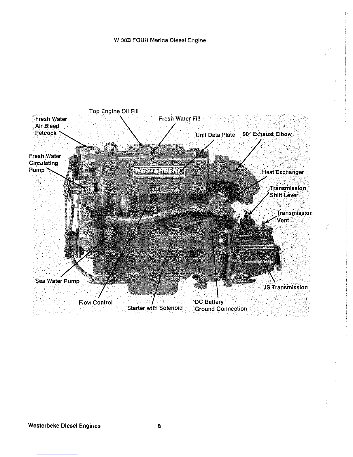
W 38B
FOUR
Marine Diesel Engine
Top
Engine
Oil
Fill
Starter
Westerbeke
Diesel
Engines
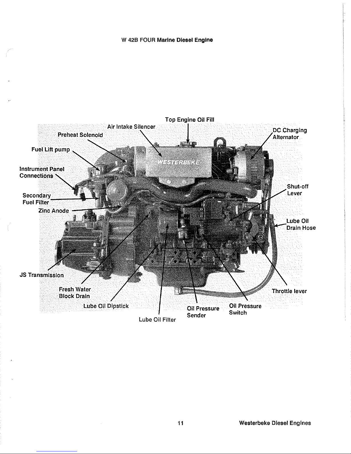
Page 11

W 388
FOUR
Marine Diesel Engine
Top Engine
Oil Fill
Air
Intake
SilElnCler
Fuel Lift pump
Connections
Secondary
Fuel
Filter'----
Zinc Anode
--
lube
Oil Dipstick
Oil Pressure
Sender
lube
Oil Filter
Oil Pressure
Switch
_"
___
'_
Oil
Throttle lever
Westerbeke Diesel Engines
Page 12

W
4213
FOUR Marine Diesel
Engine
Top
Engine
Oil Fill
90° Exhaust Elbow
Lever
Starter
Westerbeke Diesel Eng
ines
10
Page 13
Fuel Lift
pump
Fuel Filler
Zinc Anode
W
428 FOUR Marine Diesel Engine
Lube
Oil
Dipstick
Top Oil Fill
Lube
Oil Filler
11
Oil Pressure
Sender
Oil
Pressure
Switch
Oil
Throttle lever
Westerbeke
Diesel Engines
Page 14
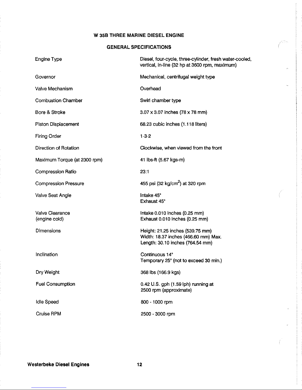
W
358
THREE MARINE DIESEL ENGINE
Engine Type
Governor
Valve Mechanism
Combustion Chamber
Bore &
Stroke
Piston Displacement
Firing
Order
Direction
of
Rotation
Maximum Torque (at
2300 rpm)
Compression Ratio
Compression Pressure
Valve
Seat Angle
Valve Clearance
(engine cold)
Dimensions
Inclination
Dry Weight
Fuel Consumption
Idle Speed
Cruise
RPM
Westerbeke
Diesel
Engines
GENERAL SPECIFICATIONS
Diesel, four-cycle, three-cylinder, fresh water-cooled,
vertical, in-line (32
hp
at 3600 rpm, maximum)
Mechanical, centrifugal weight type
Overhead
Swirl chamber type
3.07 x 3.07 inches (78 x 78 mm)
68.23 cubic inches (1.118 liters)
1-3-2
Clockwise, when viewed from the front
41
Ibs-ft (5.67 kgs-m)
23:1
455 psi
(32
kg/cm
2
)
at 320 rpm
Intake
45°
Exhaust
45°
Intake 0.010 inches (0.25 mm)
Exhaust
0.010 inches (0.25 mm)
Height: 21.25 inches (539.75 mm)
Width: 18.37 inches (466.60 mm) Max.
Length:
30.10 inches (764.54 mm)
Continuous
14°
Temporary
25°
(not
to
exceed 30 min.)
3681bs (166.9 kgs)
0.42 U.S. gph (1.59 Iph) running at
2500 rpm (approximate)
800 - 1000 rpm
2500 - 3000 rpm
12
Page 15

W 35B THREE SYSTEM SPECIFICATIONS
FUEL SYSTEM
Fuel
Injection
Pump
Injection Timing
Nozzle
Injection Starting
Pressure
Lift Pump (with filter
element)
Fuel
Filter (on engine)
Air
Cleaner
Air Flow (engine combustion)
COOLING SYSTEM
General
Operating Temperature
Fresh Water Pump
Sea Water Pump
Sea Water Flow, at 3600 rpm
(measured before discharging
into exhaust
elbow)
System
Capacity (fresh water)
LUBRICATION SYSTEM
General
Oil
Filter
Sump Capacity (includes filter)
Open flow, totally self-bleeding
No.2
diesel oil (cetane rating of 45
or
higher)
Nippondenso (Bosch M type)
23" ±
OS
BTDC (Static)
Throttle
type
2275 psi (160 kg/cm2)
12-Volt
DC;
lift
capac~y
6 ft (1.8 m)
Canistertype, with
replaceable element
Metal screen type - cleanable
71
cfm (2.0 cmm)
Fresh water-cooled
block,
thermostatically-controlled
w~h
sea water exchanger system
170 _190" F (77 -
88'
C)
Centrifugal type, metal impeller, belt.<Jriven
Positive displacement, rubber impeller, gear.<Jriven
gpm ( Ipm) approximate
6
U.S.
qts
(5.68I~ers)
Forced lubrication
by
gear pump
Paper
element, spin-on type
4.22
U.S.
qts
(41~ers)
13
Westerbeke Diesel
Engines
Page 16

W
358
THREE SYSTEM SPECIFICATIONS
Operating Oil
Pressure
Oil Grade
ELECTRICAL SYSTEM
Starting Battery
Battery
Capactty
Starting Aid
Starter
Motor
DC No-Load Current
Cold Cranking Current
Alternator
Regulator
TRANSMISSION
General
(JS Transmission)
Standard Gear Ratio
Propeller Shaft,
Direction
of
Rotation
Propeller Recommendations
(using
JS transmission
2.47:1 reduction)
Lubricating
Oil Grade
SAE Grade
Transmission
Sump
Capacity
Westerbeke Diesel Engines
35 -
55
psi (2.46 - 3.86 kg/cm
2
)
API
specijication CC
or
CD
12-Volt,
35
A-H,
(-)
negative ground
(recommended)
(45
A-H cold areas)
90 - 125 (Ampere-Hours)
12-Voit sheathed type
glow
plug
12-Volt, 1.2KW, solenoid, actuated shift
60 Amps at 11.5 Volts
(6500 rpm, min.)
190 Amps at 12 Volts
12-Volt
DC,
50 Amps
Internal regulator, built into alternator
14.4 Volts
DC ± 3 Volts
Case-hardened helical gears, with an intermediate
reverse gear. Reversing carried out by a servo
double disc system.
2.47:1
Right handed - standard transmission
16 D x 12 P - 2 blade
or
16 D x
lOP
- 3 blade
Propeller should allow the engine
to
reach
tts
full rated
RPM
(3600 + 000 - 100) at full open
throttle while underway.
API
specification of CC, CD,
SC,
SD,
or
SE
SAE 20W/20
or
SAE
30 exclusively
(DO
NOT
mix grades
of
oil
!)
(DO NOT use multigrade oils
!)
1
qt
(1
liter)
14
Page 17

W 38B FOUR MARINE DIESEL ENGINE
Engine Type
Governor
Valve Mechanism
Combustion Chamber
Bore &
Stroke
Piston Displacement
Firing
Order
Direction of Rotation
Maximum Torque (at
2400 rpm)
Compression Ratio
Compression Pressure
Valve Seat Angle
Valve Clearance
(engine cold)
Dimensions
Inclination
Dry Weight
Fuel Consumption
Idle Speed
Cruise
RPM
GENERAL SPECIFICATIONS
Diesel, four-cycle,
four-cylinder, fresh water-cooled,
vertical, in-line
(37
hp
at 3600 rpm, maximum)
Mechanical, centrifugal weight type
Overhead
Swirl chamber type
2.87 x
3.07 inches
(73
x 78 mm)
79.64 cubic inches
(1.305 liters)
1-3-2-4
Clockwise, when viewed from the front
53
Ibs-ft (7.33 kgs-m)
23:1
455 psi
(32
kgJcm
2
)
at 320 rpm
Intake
45'
Exhaust
45'
Intake 0.0098 inches (0.25 mm)
Exhaust
0.0098 inches (0.25 mm)
Height:
23.70 inches (601.98 mm)
Width: 18.37 inches (466.60 mm) Max.
Length: 33.77 inches (857.76 mm)
Continuous
14'
Temporary
25'
(not
to
exceed 30 min.)
4191bs (190 kgs)
0.42 U.S. gph (1.59 Iph) running at
2500 rpm (approximate)
750 - 950 rpm
2500 - 3000 rpm
15
Westerbeke
Diesel
Engines
Page 18

W 38B FOUR SYSTEM SPECIFICATIONS
FUEL SYSTEM
Fuel
Injection Pump
Injection Timing
Nozzle
Injection Starting Pressure
Lift Pump
Fuel Filter (on engine)
Air
Cleaner
Air Flow (engine combustion)
COOLING SYSTEM
General
Operating Temperature
Fresh Water Pump
Sea Water Pump
Sea Water Flow, at 3600 rpm
(measured before discharging
into exhaust elbow)
System Capacity (fresh water)
LUBRICATION SYSTEM
General
Oil Filter
Sump Capacity (includes filter)
Westerbeke
Diesel
Engines
Open flow, totally self-bleeding
No.2
diesel oil (cetane rating
of
45
or
higher)
Nippondenso (Bosch M type)
23° ±
OS
BTDC (Static)
Throttle type
2275 psi (160 kg/cm2)
12-Volt DC; lift capacity 6 ft (1.8 m)
Canister type, with replaceable element
Metal screen type -cleanable
82.9 cfm (2.34 cmm)
Fresh water cooled block,
thermostatically-controlled
with sea water exchanger system
170 - 190° F (77 -
88°
C)
Centrifugal type, metal impeller, belt-driven
Positive displacement, rubber impeller, gear-driven
gpm
( Ipm) approximate
7
U.S. qts (6.6 liters)
Forced lubrication by gear pump
Paper element, spin-on type
4.75
U.S. qts (4.5 liters)
16
Page 19

W 38B FOUR SYSTEM SPECIFICATIONS
Operating Oil Pressure
Oil Grade
ELECTRICAL SYSTEM
Starting Battery
Battery Capacity
Starting Aid
Starter
Motor
DC No-Load Current
Cold Cranking Current
Alternator
Regulator
TRANSMISSION
General
(JS Transmission)
Standard Gear Ratio
Propeller Shaft,
Direction
of
Rotation
Propeller Recommendations
(using
JS transmission
2.47:1 reduction)
Lubricating
Oil Grade
SAE Grade
Transmission
Sump
Capacity
35 - 55 psi (2.46 - 3.86 kg/cm
2
)
API
specification CC
or
CD
12-Volt, 35 A-H,
(-)
negative ground
(recommended)
(45
A-H cold areas)
90 - 125 (Ampere-Hours)
12-Volt sheathed type
glow
plug
12-Volt, 1.2KW, solenoid, actuated shift
60 Amps at 11.5
Volts (6500 rpm, min.)
190 Amps at 12
Volts
12-Volt DC, 50 Amps
Internal regulator, built into alternator
14.4
Volts DC ± 3 Volts
Case-hardened helical gears, with an intermediate
reverse gear. Reversing carried out by a servo
double disc system.
2.47:1
Right handed - standard transmission
180
x 12 P - 2 blade
or
18 0 x 10 P - 3 blade
Propeller should allow the engine
to
reach
its full rated
RPM
(3600 + 000 - 100) at full open
throttle while underway.
API
specification
of
CC,
CD,
SC,
SO,
or
SE
SAE
20W/20
or
SAE 30 exclusively
(DO
NOT
mix grades
of
oil
1)
(DO
NOT
use multigrade oils
!)
1
qt
(1
liter)
17
Westerbeke Diesel Engines
Page 20

W 42B FOUR MARINE DIESEL ENGINE
Engine
Type
Governor
Valve Mechanism
Combustion Chamber
Bore &
Stroke
Piston Displacement
Firing Order
Direction of Rotation
Maximum Torque (at
2500 rpm)
Compression Ratio
Compression Pressure
Valve Seat Angle
Valve Clearance
(engine cold)
Dimensions
Inclination
Dry Weight
Fuel Consumption
Idle Speed
Cruise RPM
Westerbeke
Diesel
Engines
GENERAL
SPECIFICATIONS
Diesel, four-cycle, four-cylinder,
fresh water-cooled,
vertical, in-line
(42
hp
at 3600 rpm, maximum)
Mechanical, centrifugal weight type
Overhead
Swirl
chamber type
3.07 x 3.07 inches (78 x
78
mm)
90.93 cubic inches (1.49
liters)
1-3-2-4
Clockwise,
when viewed from the front
561b-ft (7.74 kg-m)
23:1
455 psi (32 kg/cm
2
)
at 320 rpm
Intake
45'
Exhaust
45'
Intake 0.0098 inches (0.25 mm)
Exhaust
0.0098 inches (0.25 mm)
Height:
23.70 inches (601.98 mm)
Width: 18.37 inches
(466.60 mm) Max.
Length: 33.77 inches (857.76 mm)
Continuous
14'
Temporary
25'
(not
to
exceed
30
min.)
4191bs (190 kgs)
0.42 U.S.
gph
(1.59 Iph) running at
2500 rpm (approximate)
750 - 950 rpm
2500 - 3000 rpm
18
Page 21

W 42B
FOUR
SYSTEM SPECIFICATIONS
FUEL SYSTEM
Fuel
Injection Pump
Injection
Timing
Nozzle
Injection Starting Pressure
Lift
Pump
Fuel
Filter (on engine)
Air
Cleaner
Air Flow (engine combustion)
COOLING SYSTEM
General
Operating Temperature
Fresh Water
Pump
Sea
Water Pump
Sea
Water Flow, at 3600 rpm
(measured before discharging
into exhaust elbow)
System Capacity (fresh water)
LUBRICATION SYSTEM
General
Oil Filter
Sump Capacity (includes filter)
Open flow, totally self-bleeding
NO.2 diesel oil (cetane rating 0145
or
higher)
Nippondenso (Bosch M .type)
23'
± 0.5' BTDC (Static)
Throttle type
2275 psi
(160 kg/cm
2
)
12-Volt
DC;
lift
capacity 6
ft
(1.8 m)
Canister type, with replaceable element
Metal screen type - cleanable
94.0
clm
(2.66 cmm)
Fresh water cooled block,
thermostatically-controlled
with sea water exchanger system
170
-190'
F (77 -
88'
C)
Centrifugal type, metal impeller, belt-driven
Positive displacement, rubber impeller, gear-driven
gpm
( Ipm) approximate
7
U.S. qts (6.6 liters)
F.orced lubrication
by
gear
pump
Paper element, spin-on type
4.75
U.S. qts (4.5 liters)
19
Westerbeke
Diesel
Engines
Page 22
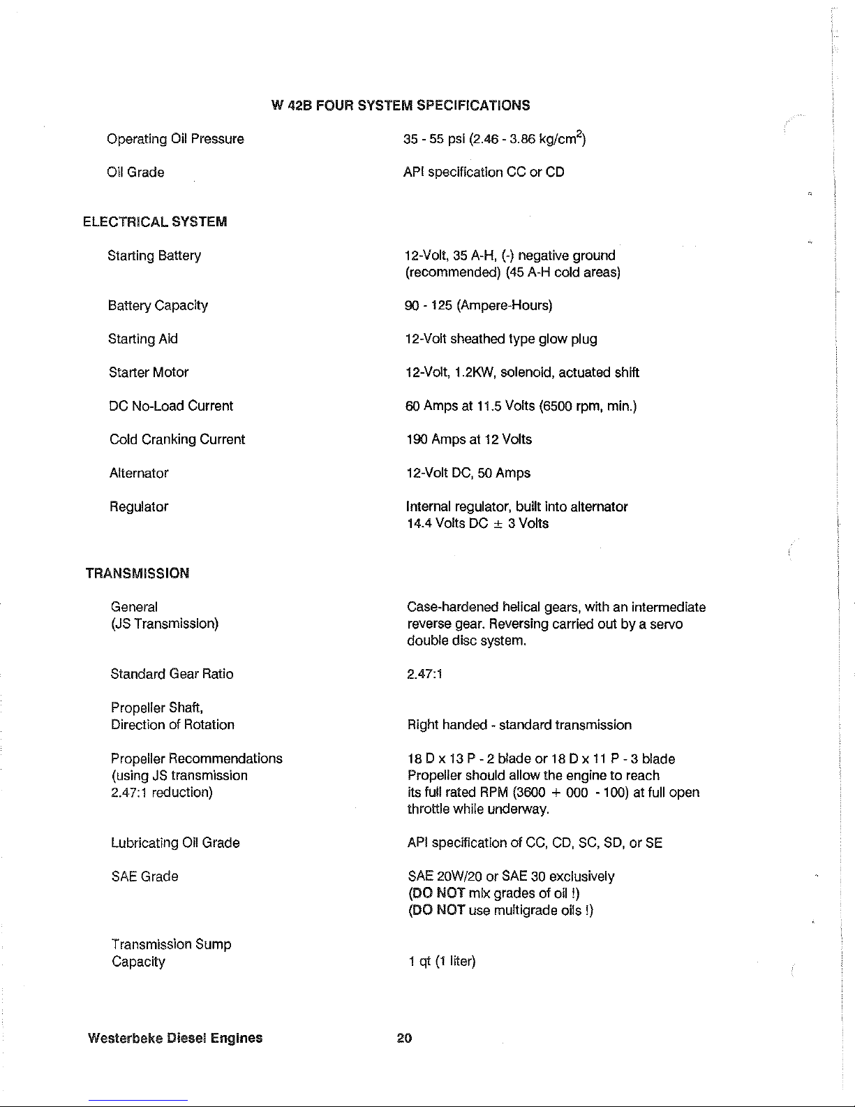
W 42B FOUR SYSTEM SPECIFICATIONS
Operating Oil Pressure
Oil
Grade
ELECTRICAL SYSTEM
Starting Battery
Battery Capacity
Starting Aid
Starter
Motor
DC No-Load Current
Cold Cranking Current
Alternator
Regulator
TRANSMISSION
General
(JS Transmission)
Standard Gear Ratio
Propeller Shaft,
Direction of Rotation
Propeller Recommendations
(using
JS transmission
2.47:1 reduction)
Lubricating
Oil Grade
SAE Grade
Transmission
Sump
Capacity
Weslerbeke Diesel Engines
35 - 55 psi (2.46 - 3.86 kg/cm
2
)
API
specification CC
or
CD
12-Volt,
35
A-H,
(-)
negative ground
(recommended) (45 A-H
cold areas)
90 - 125 (Ampere-Hours)
12-Volt sheathed type
glow
plug
12-Volt,
1.2KW, solenoid, actuated shift
60 Amps at 11.5
Volts (6500 rpm, min.)
190 Amps at 12
Volts
12-Volt
DC,
50
Amps
Internal regulator, built into alternator
14.4
Volts DC ± 3 Volts
Case-hardened helical gears, with an intermediate
reverse gear. Reversing carried out
by
a servo
double disc system.
2.47:1
Right handed - standard transmission
18 D x 13
P - 2 blade
or
18 D x
11
P - 3 blade
Propeller should
allow the engine
to
reach
its full rated
RPM
(3600 + 000 - 100) at full open
throttle
while underway.
API
specification
of
CC,
CD, SC,
SD,
or
SE
SAE 20W/20
or
SAE
30 exclusively
(DO
NOT
mix grades
of
oil
!)
(DO
NOT
use multigrade oils
!)
1 q!
(1
liter)
20
Page 23

INSTALLATION CHECKS
General
Because the crafts
in
which Westerbeke engines are installed vary in design, installation procedures will vary
according
to
your craft's specific design. The intent of this section
is
not
to
advise boatyards
or
installers
on procedures alreadywell-developed and well-understood. However, the owner/operator must
realize there
are details of the installation which require periodic checks
to
ensure the best operating conditions for the
equipment and safe operating conditions for the personnel on board. Proper location and installation
of
the
diesel engine in the vessel are of prime importance.
Factors in the installation that must be considered are ventilation,
to
aid in cooling and
to
provide air for en-
gine combustion; exhaust system,
to
properly discharge raw cooling water, quiet the exhaust and expel ex-
haust gas; cooling water supply; fuel supply; and electrical connections.
CAUTION
For safety reasons, the engine and transmission are NOT filled with lubricating oil for shipment. Before leaving the factory, however, each engine with transmission
is
thoroughly tested
with oil in it. This testing, among other things, provides
all internal parts with a coating of oil.
This oil acts
as
a preservative, providing reliable protection against corrosion for at least one
year if the engine and transmission are properly stored.
Location
The location should be dry, and in an area where bilge water
or
water from above cannot splash on the engine. The engine should be properly ventilated and accessible for minor servicing and repairs (access for
major repairs should be given consideration as well). The location must be properly ventilated
to
provide
fresh air for engine combustion. The engine's lubrication oil sump dipstick, the fresh water and oil fills, and
the transmission's dipstick and transmission
or
oil fill port must be accessible.
FILL
CM'
COOLANT
RECOVERV
__
COCKPIT
TANK
.fr
AlnIl:Nan:~~~~~B~~==~'
MOUNTING
STRAP
POSITIONS
CABIN
IHST~~LATIOH
RHGL~
MUST
NOT
IOXCEED
14'
Please note that the engine's installation angle cannot exceed
14'
from the horizontal plain.
21
Westerbeke Diesel Engines
Page 24

Rigging and
lifting
The engine
is
fitted with lifting eyes. Rope
or
chain slings capable of supporting the engine's weight should
be attached
to
the eyes and the engine lifted by means of tackle attached to these slings. The lifting eyes
have been designed
to
carry the full weight
of
the engine; therefore, auxiliary slings are not required or
desired.
CAUTION
Slings
must not be so short as
to
place significant sheer stress on the engine's lifting eyes.
Strain
placed on the engine's lifting eyes by the lifting sling must not be in excess of
100 from
the
vertical plain.
10·
ENGINE
SLING
LIFTING
ANGLE
MUST
NOT
EXCEED
10'
LIFT
ING
EYE
The general rule in moving engines
is
to
see that all
of
the equipment used
is
amply strong and firmly fixed
in
place. Move the engine a little at a time and
see
that
it
is
firmly supported. Eliminate the possibility of ac-
cidents by avoiding haste. Do not
lift the engine by its propeller coupling, or pry against this coupling with
a crowbar, because excessive pressure
of
this type may distort the coupling.
In
certain situations it may be necessary
to
lift the engine
in
positions otherthan the horizontal position. Cer-
tain situations exist
by
which the engine must be lowered endwise through a small hatchway which cannot
be made
larger. Under these conditions,
if
the opening
of
the hatchway is extremely narrow, it is possible
to
reduce,
to
some extent, the outside dimensions of the engine
by
removing external components such as
the alternator, the
cooling system's piping, the heat exchanger, certain filters, the mounting lugs and other
obstructive equipment. This accessory equipment
should be removed
by
a competent mechanic and spe-
cial care should be taken
to
avoid damaging any exposed parts. In addition, be careful not
to
allow dirt from
entering any opening created by the
removal of equipment. Parts removed should be returned to their
respective position as soon as the engine has
cleared the obstruction.
In case it becomes necessary
to
hoist the engine either front-end upwards or transmission-end upwards, the
attachment of
slings must be done carefully
to
avoid the possibility of damaging the parts on which the weight
may bear.
Special rigging
work
is
best done by someone experienced and competent in handling heavy
machinery.
Westerbeke
Diesel Engines
22
Page 25

Engine
Bolls
Bronze or stainless steel hanger bolts of appropriate size are recommended for use through the engine's
flexible mounts. Less preferred are lag screws because their hold on the
wood
is
weakened every time they
are moved, whereas the hanger bolts stay
in
position. If the nut on top of the hanger bolt
is
removed
to
allow
the engine
to
be lifted from its resting place, the hanger bolt itself remains in place as a stud. Consequent-
ly, the
bond
between the hanger bolt and the wood is not weakened by the removal of the nut or the engine.
Foundation
lor
the Eng
ine
A
good
engine bed contributes much toward the satisfactory operation of the engine. The engine's bed
must be rigidly constructed and neither deflect nor twist when it
is
subjected
to
the engine's weight or
to
the
pressures that the boat may experience while operating
in
rough seas. The bed must keep the engine's
alignment within one
or
two
thousandths of an inch of this position at all times. The bed has
to
withstand
the forward push
of
the propeller shaft which pushes against the thrust washer bearing which finally pushes
against the engine's bolts and bed.
in fiberglass hulls, we recommend that similar wooden stringers as in wooden hulls be formed, fitted, and
then glassed securely
to
the hull. This allows the hanger bolts
to
be installed firmly in the wood, thereby
reducing noise and transmitted vibration.
The engine support stringers must be as wide or wider than the engine mounting isolator.
Isolator overhang
and/or rounded stringer surfaces are detrimental
to
the isolators' ability to retain vibration.
Preformed fiberglass engine beds, when used, should be of sufficient thickness
to
properly support the en-
gine and should be well-glassed to the
hull when in-
stalled.
The temptation
to
install the engine on a pair
of
fiberglass angle irons must be resisted. Such construction will
allow engine vibration
to
pass through
to the
hull. Flexible mounts require a firm foundation
against which they must act if they are to perform their
function. When possible, follow bed design A and
avoid bed design
B (refer
to
the illustration).
Supports between the bed stringers, and extending
from the stringers
to
the hull, may be required for
proper support and
to
aid
in
the absorption of vibra-
tions.
GOOD
A
BAD
B
Note:
Avoid
excessive
height,
use
solid
stringer
construction
(A).
23 Westerbeke Diesel Engines
Page 26

Propeller Shaft
Coupling
The propeller shaft coupling fitted
to
the transmission's output flange must transmit not only the power of
the engine
to
turn the propeller shaft and propeller, but must also transmit the thrust of the engine/transmis-
sion either ahead
or
astern.
The coupling bore should be carefully machined for a slight forced fit onto the shaft and an accurate mating
surface for the coupling
to
the output flange
of
the transmission.
For all engine models, a propeller half-coupling, bored
to
shaft size for the specific order,
is
supplied. The
coupling either has a keyway with set screws or
is
of
the clamping type.
The forward end
of
the propeller shaft has a long straight keyway. Any burrs should be removed from the
shaft's end. The coupling should be a light drive fit on the shaft and the shaft should not have to be scraped
down or filed in order
to
get a fit. It
is
important that the key be properly fitted both to the shaft and
to
the
coupling. The key should fit the side of the keyway closely, but should not touch the
top
of
the keyway in
the hub
of
the coupling.
If
driving the coupling over the shaft
is
difficult, the coupling can be expanded by heating it in a pail of boil-
ing water. The face
of
the propeller coupling must be exactly perpendicular
to
the centerline or axis
of
the
propeller shaft.
Propeller
The type and size
of
propeller varies with the gear ratio and must be selected
to
fit the application, based
upon boat tests. To utilize the full power of the engine, and to achieve
ideal loading conditions, use a propeller
which will permit the engine to reach its
full rated
RPM
at full throttle while under a normal load and while it
is
moving the boat forward through the waler.
Alignment
of
the
Engine
The engine must be exactly aligned with the propeller shaft
in
the proper fashion.
No
matter what material
is
used
to
build a boat the material will be found
to
be flexible to some extent; hence, the boat's hull will
change its shape
to
a greater extent than is usually realized when the boat is launched and operated
in
the
water. Therefore,
it becomes extremely important to check the engine's alignment at frequent intervals and
to
correct any errors when they appear.
Misalignment between the engine and the propeller shaft often creates serious
problems which are often
blamed on other areas suspected of causing the trouble. Misalignment will cause excessive bearing wear,
rapid shaft wear and will,
in
many cases, reduce the
me
of
the boat's hull by loosening the hull's fastenings.
A bent propeller shaft
will have the exact effect as those just stated; therefore, a perfectly straight propeller
shaft is
absolutely necessary. One particularly annoying result
of
misalignment may be leakage of transmis-
sion oil through the transmission's rear oil
seal. If oil
is
leaking from this seal, check and make sure that the
coupling's
alignment
is
within the limits prescribed on page
25.
Never attempt a final alignment with the boa! on land. The boat should be in the water and have had an opportunity
to
assume its final water form. The best lime
to
perform the propeller shaft/transmission coupling
alignment
is
with the fuel and water tanks about half full and all the usual equipment on board, and after the
main mast has been stepped and the
final rigging has been accomplished.
Westerbeke
Diesel
Engines
24
Page 27

Take plenty of time in making this alignment and
do
not be
satisfied with anything
less than perfect results.
The alignment is correct when the shaft can
be
easily
slipped backward and forward into the counterbore, and
when a feeler gauge indicates that the flanges come
together at
all points. The alignment between the propeller
shaft coupling and the engine's coupling can contain an
error
no
greater than one thousandth
of
an
inch per inch of
the coupling diameter. For example, if your propeller shaft
coupling
is
three inches in diameter, the maximum error
that can be allowed in the
alignment is three thousandths
of an inch (.003).
In
making the final check for alignment, the
engine's half
coupling should be held in one
position and the
alignment with the propeller
coupling
tested with the propeller coupling in
each
of
four positions
(A),
while rotated
90'
be-
tween each
pOSition.
This test will also check
whether the propeller's
half-coupling is in exact
alignment on
its shaft. Then, keeping the
propeller coupling in one position, the alignment
should be checked
by
rotating
the
engine's
half-coupling
in
90'
increments,
checking dimension
A while in each
90'
posi-
tion until the half-coupling has been rotated full
circle.
The engine's alignment should be rechecked
after the boat has been
in
service for one
to
three weeks and, if necessary, perform the
alignment again. Usually it will be found that
the engine
is
no
longer in alignment. This does
not mean that the work has been done improperly at first; rather,
it
means that the boat
has taken some time
to
take its final shape and
that
the
engine's bed and stringers have
probably absorbed some moisture.
It may
even be necessary
to
realign the coupling hal-
ves
again at a later time.
25
.B93
FEELER
GAGE
PROPELLER
SHAFT
Westerbeke Diesel Engines
Page 28

Exhaust System
The exhaust system provides an outlet line to vent engine exhaust gases out
01
and away from the vessel.
The system also discharges sea water which has passed through the engine's sea water circuit
by
mixing
it
with hot exhaust gases. This mixing helps cool the exhaust gases and exhaust elbow and plumbing. The
exhaust system and the sea water supply to the exhaust
must be configured to prevent the siphoning
of
sea
water into the exhaust through the sea water
cooling circuit and
to
prevent the entry
of
sea water into the
exhaust through the circuit's through-hull discharge port.
If not prevented, sea water entering through the
discharge port can
fill the exhaust system muffler and enter the engine's cylinders. This will prevent proper
starting and possibly cause damage
to
internal engine components.
The sea water supply hose
to
the exhaust system water injection elbow should be routed (looped) at least
12
inches above the vessel water line.
An
anti-siphon break should be installed, when needed, at the
lop
of
this loop. The
top
of
the
loop
should be placed high enough above the vessel's water line so
as
to
remain
above the water
line when the vessel
is
underway, no matter what the angle of heel
or
roll may be.
[HGINE~aboye
Wgttr
line
l~
LD.
INSULAT
E
fOLD/WRTER-INJECTED
ELBOW
NINIMU~
OF
6-
INCHES
ABOVE
VESSEL'S
WATER
LINE.
ENGINE-below
water
line
SrPItOH
....
EAK
I'ART
If
33327'
ENGINE
INSTALLATIONS
WITH
EXHAUST
MANI-
FOLD/WATER
INJECTED
ELBOW
AT
OR
BELOW
VESSEL'S
WATER
LINE.
1*
LD.
4B~
MAX.
HYDRO-HUSH
~J
CAIJIION:
Vented
loop
Must
be
in
a
location
where
it
will
rem~in
~bove
the
water
line
during
all
angles
of
vessel
operation_
The sea water supply through-hull sea
cock
fittings must be of the flush-hull type. High-speed scoop type
of fittings should
nol
be used as they tend
to
encourage siphoning.
The exhaust discharge from the water
lift muffler should be routed well above the water line then downward
to
the through-hull discharge. This routing will prevent sea water entry
if
the through-hull discharge fitting
becomeS submerged when the vessel heels
or
rolls while under way, or
is
subjected to following sea con-
ditions. Refer
to
the ligures shown above for recommended exhaust system installations.
Weslerbeke Diesel Engines
26
Page 29

Exhaust Back-Pressure
The exhaust discharge hose must be of adequate size and mini-
mal
run
to
prevent excessive exhaust back-pressure. Exhaust
back-pressure should be checked before the engine is put into
~
service. (Refer
to
the illustration.) Excessive back-pressure will
~
affect the engine's performance.
To measure for
back-pressure, use a mercury manometer, a pres-
sure gauge,
or
a water column. A boatyard
or
marine mechanic
should have a manometer or a pressure gauge.
..
..
"
"
-Insulation
Exhaust
Elbow
Measure back-pressure at
the
exhaust elbow when the engine
is
running
at
3600
rpm. Back-pressure, as measured
by
a
manometer, a pressure gauge,
or
water column, should not be
over the specifications listed below.
2.
Exhaust
NOTE: Other pressure gauges may be available to test for
exhaust
baCk-pressure.
Check
with a competent
mechanic.
A water column can be made by taking a clear plastic tube and
taping one end of the tube
along a yardstick and fitting the other
end
of
the tube with a 1/4 inch NPT (National Pipe Tap) pipe fit-
ting.
Measure back-pressure at the exhaust
elbow when the engine is
running at 3600 rpm.
Dimension A cannot exceed 39 inches
of
water.
Back-pressure, as measured by a gauge instrument, should not
exceed the
following specifications:
Specilicalions:
3 inches
01
mercury (0.104 kg/cm
2
)
39 inches
01
water
in
a water column
(.099 kg/cm
2
at
4'
C)
22
ounces psi
1 1/2 psi
."
"
I~
~~
Mercury
Manometer
\
\
Excessive back-pressure can be caused
by
a small diameter exhaust hose, a small muffler, sharp bends in
the exhaust hose, improper fittings, water pockets, and a high volume
of
water
in
the exhaust system due
to
the length of the exhaust discharge hose. The use
of
elbows and fittings in the exhaust discharge hose's
routing should be limited since these will create flow restrictions and contribute
to
exhaust back-pressure.
The engine's exhaust system must be separate from any other engine's exhaust system. Dry portions of the
exhaust system
between the engine's exhaust manifold and the water injected exhaust elbow must be insu-
lated
to
hold in the heat.
21
Westerbeke Diesel Engines
Page 30

Exhaust
System
Failures
When the engine's sea water
is
fed into an exhaust system so that the full stream
of
this water strikes a sur-
face, erosion takes place. This erosion may cause premature failures. The proper design
of
either a water
jacketed
or
water injected "wet" exhaust system
to
prevent this problem requires that the sea water inlet be
positioned so that the entering stream of sea water does not directly strike a surtace.
In addition, the velocity
of the entering sea water stream should be
as
low as possible, which can be achieved by having inlet fittings
as
big
in
diameter as possible.
The best protection against exhaust system leaks
is
to
routinely inspect the complete exhaust system. Check
for leaks around manifolds, gaskets, and welds. Make sure exhaust lines are not heating surrounding areas
excessively.
If excessive heat is present, correct the situation immediately. If you notice a change in the
sound or appearance of the exhaust system, inspect the exhaust system and correct the cause.
Exhaust risers
installed off the exhaust manifold should not exceed 8 Ibs
in
total weight when rigidly con-
nected. Excessive weight and vibration can result
in
a manifold failure and/or the fracturing of the riser from
the manifold at its attachment. Dry portions of the exhaust connected
to
the manifold, which lay before the
water injected exhaust system,
MUST
be properly insulated
to
retain the exhaust heat within the exhaust
pipe.
Although diesel engine exhaust gases are not as toxic
as
exhaust fumes from gasoline en-
gines, carbon monoxide is present in diesel exhaust fumes in less concentration. Carbon
monoxide is a dangerous gas that can cause unconsciousness and
is
potentially lethal. Some
of
the symptoms
or
signs
of
carbon monoxide inhalation
or
poisoning are as follows:
o Dizziness
o Vomiting
o
Intense Headache
o Muscular Twitching
o Weakness and
Sleepiness
o Throbbing in Temples
If you experience any
of
the above symptoms, get out into fresh air immediately.
Make sure there are
no
unnecessary objects suspended from any portion of the exhaust lines. Excessive
weight could cause deflection or distortion of the
lines, resulting
in
damage or leaks. Inspect insulated por-
tions
of
the exhaust system
to
make sure there
is
no deterioration
of
the insulation.
Westerbeke
Diesel
Engines
28
Page 31

Exhaust Elbow Installation
The Westerbeke Corporation offers a 45°and 900exhaust
elbow as well as an exhaust riser you can install on your
propulsion engine. Refer
to
the instructions below when
installing the exhaust elbow purchased for your engine.
1.
Coat only one side
of
the exhaust gasket with
'''High
Tack" adhesive sealant. Place this coated surface
against the exhaust manifold's exhaust port flange (the
gasket should stick
to
the flange without falling off).
2.
Place the clamp over the elbow's flange. Place your ex-
haust elbow against the exhaust manifold's flange so
the exhaust manifold's flange rests snug against the
exhaust elbow's flange with the gasket centered between
the two.
Now
slip the exhaust clamp over both flanges.
3.
A.
Tighten the clamp just enough so the exhaust elbow
can remain attached
to
the manifold and still be
rotated.
B.
The exhaust elbow discharge must be directed
downward
so the mixture
of
sea water and exhaust
gases will
flow/fall downward into the exhaust muf-
fler which must be positioned below the exhaust
elbow. There should be no loops
or
rises
in
the exhaust hose connected between the exhaust elbow
and the
muffler, as these would trap water and pos-
sibly allow water
to
flow back into the engine during
starting
or
at shut down.
4.
Adjust the elbow
by
rotating it until the desired align-
ment with the exhaust piping is acquired.
5. Carefully tighlen the clamp between 2
to
3 Ib-I!,
or
24
to
35 Ib-in,
or
0.2710
0.41 kg-m.
CAUTION
Approach the :I Ib-f!
torque
limit
with
caution.
The
clamp's
threads
will
break
if
more
than
:I
Ib-
tI is applied
to
lhe
clamp.
6.
When the engine is started for the first time with the new
elbow, check Ihis exhaust manifold/elbow connection
for
leaks. II a leak exists, correct it immediately.
* Manufactured
by
Permatex Company, Brooklyn, N.Y.
29
CLAMP
45°
ELBOW
ClAMP
90° ELBOW
EXHAUST RISER
CLAMP
Weslerbeke
Diesel Engines
Page 32

Oil Drain Hose
An
oil
sump drain hose
is
installed
on
the
engine
with the discharge
end
secured
by
a bracket at
the
front
of
the
engine.
Oil
may
be
drained from this
hose
by removing
the
cap
and
the discharge
end
of
the
hose
from
the
support bracket
and
lowering the
hose
into a container.
The
hose
cap
fitting
is
1/4 inch
NPT
(National
Pipe
Tap)
and
can
be
extended, or
have
a pump added for easier
removal
of
the
old
oil,
if
desired.
Connecting Pressure Sensing Devices
to
Oil
Galleries
Oil
pressure sensing devices,
such
as
senders
and
switches, must not
be
connected to
an
engine's
oil
gal-
lery with the
use
of extended nipples or
tees.
The
reason
is
simply that continued engine vibration
causes
fatigue
of
the fittings
used
to
make
such a connection.
If
these
fittings
fail,
the
engine
loses
its
oil
pressure
and
quickly
seizes.
When
additional sensing devices such
as
switches or sensors
need
to
be
installed that function
on
engine
oil
pressure, these devices
must
be
bulkhead-mounted
and
connected to the
oil
gallery using
an
appropriate
grade
of
lubricating
oil
hose.
Any fittings
used
to connect
the
hose to the gallery must
be
of
steel
or
malle-
able iron composition.
Brass
must not
be
used
for this application.
Cooling System
The
engine
is
fresh
water cooled
by
an
engine-mounted
heat
exchanger.
Sea
water
is
used
as
the heat
exchanger's
cooling medium.
Sea
water
is
pumped into the exchanger
by a sea
water
pump,
where
it
cools
the
fresh
water that circulates through
the
engine block,
and
is
then injected into
the
exhaust discharge, car-
rying with it
the
heat removed from the engine's
fresh
water cooling
system.
Sea
water should
be
supplied to the
sea
water pump through a flush-type through-hull fitting using a wire-
reinforced hose between the through-hull fitting
and
the
sea
water pump.
The
sea
water should
be
directed
through a visual-type
sea
water strainer, which will trap debris before ~ reaches
the
sea
water pump
and
the
heat exchanger,
and
then
be
delivered to
the
pump. Hoses routed from
the
through-hull fitting to
the
strainer
and
to
the
sea
water pump should
be
wire-reinforced to
prevent
the
hose
from collapsing while the engine.
is
running (suction from
the
pump may collapse a non-reinforced
hose).
The
sea
water strainer should
be
mounted
at
or below the water line to
make
sure
the
sea
water line
remains
primed.
CAUTION
DO
NOT
use
a scoop-type through-hull fitting
as a means
of supplying
sea
water to the
en-
gine.
Water pressure against this type of fitting, while
the
vessel
is
under
sail,
can
push
sea
water past the
sea
water pump's impeller into the engine's exhaust
system,
filling
it
and
the
engine
as
well.
Flush-type,
clear,
through-hull fittings
are
recommended
and
should
be
lo-
cated
on
the
hull
so
as
to
be
below
the
waterline during
all
angles
of
boat operation.
The
use
of common-type street elbows
is
not recommended for plumbing the
sea
water cir-
cuit.
These
generally
have
very restrictive inside diameters. Machine fittings
are
preferred.
Westerbeke Diesel Engines
30
Page 33

Automatic
Alarm
System
High Water Temperature Alarm
A high water temperature alarm buzzer has been supplied with the instrument panel.
If the engine's fresh
water coolant reaches
205" F (96"
C),
a water temperature switch on the engine closes causing the alarm
buzzer to emit a continuous signal. Refer to the
"DESCRIPTION OF INSTRUMENT PANELS" section of this
manual for the location
of
the alarm in your engine panel, page
35.
Low
Oil Pressure Alarm
A
low
oil pressure alarm switch
is
located off the engine's oil gallery. This switch monitors the engine's oil
pressure.
Should the engine's oil pressure fall
to
10
-15
psi, the switch will close sounding this same alarm.
In this event, the alarm will emit a pulsating signal. Refer to the "DESCRIPTION OF INSTRUMENT PANELS"
section
of
this manual for the location
of
the alarm in your engine panel, page
35.
Sea Water
Intake
System
Make sure the intake system (sea water cooling system)
is
in proper order. Check that the hull inlet, sea
cock
and strainer are unobstructed. Sea cocks and strainers should be at least one size greater than the
inlet thread
of
the sea water pump. The strainer should be of the type that may be withdrawn for cleaning
while the vessel is at sea and should be mounted below the water
line
to
ensure self-priming. Inspect the
sea water lines
to
make sure there are no collapsed sections, which would restrict water flow. Make sure
there are no air leaks at any
of
the connections.
Fuel
System
The fuel system should be installed in such a manner
as
to
allow the engine-mounted fuel lift pump
to
main-
tain a positive inlet pressure
to
the injection pump under all operating condftions. The minimum size of the
fuel supply
line and fuel return line
is
1/4 inch, inside diameter, and there
shOUld
be a primary fuel filter in-
stalled between the fuel tank and the fuel lift pump. Only one fuel filter
is
installed on the engine, between
the mechanical fuel lift pump and the injection pump; this
Iilter has a replaceable filter element.
The fuel tank's fuel pickup tube should be clear and unobstructed. No screens
or
gauze strainers should be
Incorporated in the fuel pickup tube.
Make sure that the fuel supply and return
lines are securely anchored
to
prevent chafing and that all fittings
are sufficiently tightened to prevent leaking. Also make sure your fuel system has a positive shut-off valve;
know its location and how it operates.
NOTE: DO NOT use spring-loaded check valves in the fuel supply line in lieu
of
mechanical
shut-off valves. This type valve can create fuel starvation problems for the engine's fuel sys-
tem.
Fuel tanks that are located below the engine's fuel system level must have its fuel return at the tank extending down into the tank
in
the same manner as the pickup tube, otherwise fuel siphoning out of the engine's
fuel system through the return will take place.
31
Westerbeke Diesel Engines
Page 34

Make sure the fuel tank filler
is
properly sealed
to
prevent water entry should it become awash. The fuel
tank's vent should be routed so
as
to
prevent water entry as well.
Be
sure there
is
a fire extinguisher installed near the unit and that it
is
properly maintained. Be familiar with
its use.
An
extinguisher with the NFPA rating of ABC
is
appropriate for all applications in this environment.
Electrical
System
The electrical system should be checked
to
make sure all wiring harnesses are tied down properly with
clamps or plastic ties, spaced at intervals close enough
to
prevent chafing from vibration. Check
to
make
sure
all the engine's harness connections are tight and that they are made to the appropriate terminals.
IWARNINGI
Do not smoke
or
allow an open flame near batteries. Lead acid batteries emit hydrogen, a
highly-explosive gas. Turn off the emergency switch
in
the positive line
of
battery.
Make sure the positive (
+ ) battery connection
is
connected to the battery connection
of
the starting solenoid.
The negative
(-)
battery connection should be connected
to
the system ground (the engine block).
When servicing the battery
or
checking the electrolyte level, wear rubber gloves, a rubber
apron, and eye protection. Battery acid may inadvertently splash on skin
or
into eyes when
removing electrolyte caps.
Check
level and specHic gravity
of
battery electrolyte
to
ensure maximum engine starting efficiency. Make
sure terminals are clean and tight.
Ventilation
The ventilation requirements
of
the engine include the following: combustion air
is
required for the engine's
cylinders and ventilating air
is
required to clear the bilges below the engine, as well as the compartment in
which the engine
is
located, of heated air produced during engine operation and
of
potentially toxic and
flammable diesel fumes. Refer
to
the "SYSTEM SPECIFICATIONS" section of this manual for engine airflow
requirements, page
13
for the W 35B, page
16
for the W 38B, and page 19 for the W 42B.
Weslerbeke
Diesel
Engines
32
Page 35

PREPARATION FOR STARTING
This section of the manual provides the operator wtth preparation, initial starting, break-in, starting (cold
or
warm), and stopping procedures. Follow the procedures as presented,
for
the conditions indicated, and
your Westerbeke engine set
will give you reliable performance and long service life.
Fill
your
engine with oil up
to
or
near the upper limn on the
dipstick (the installation angle may have an effect
on
the
dipstick reading).
Select readily available lubricating oil with
an
API
specification
of
CC
or
CD
and an SAE number suitable
for the temperature in
your
operating area (see page 60). For
the quantity
01
oil needed in your engine, refer
to
the "SYS-
TEM SPECIFICATION" section
01
this manual, page 13 for the
W
35B, page 16
lorthe
W 38B, and page 19 for the W 42B.
Fill the
JS transmission
to
the FULL mark
on
the dipstick with
the correct lubricant. (The
JS transmission takes 1 U.S. qt
or
1 liter
of
oil. Refer
10
your engine's "SYSTEM SPECIFICA-
TION"
section
of
this manual
lor
a listing of oil grades
to
be
used in this engine.)
UPPER
LIMIT
~~:;;;:;_;:;;_~::_~
__
(_HORMRL
LEVEL)
LOWER
LIMIT
Each unit is supplied with a coolant recovery kit (#24977)
as
standard equipment,
to
which the following ap-
plies:
A.
Remove the pressure cap from the engine's exhaust manifold and slowly fill the engine's
COOling
sys-
tem with a mixture of water and antifreeze
suitable for your temperature zone. (See the "COOLING SYS-
TEM"
section
01
this manual, page 53.) Operate the engine and observe the coolant level
in
the manifold.
Maintain this level
to
the base
01
the Iiller neck. Once the engine reaches its operating temperature (170
-
190'
F),
make sure there is coolant flow
to
the domestic water heaters when installed. Top off the cool-
ing system
and Instalilha pressure cap.
8.
Make sure the plastic recovery tank is properly mounted near the unit (with the bracket provided), in a
location where it can be monitored and filled easily. The recovery tank should be mounted at manifold
level
or
above. In these installations that require
it,
the plastic recovery tank can be mounted below the
exhaust
manifold's level.
c.
Add coolant
to
the plastic tank after the engine has been started and after the engine's operating
temperature has been reached
to
make sure all air is expelled from the manifold and the engine's cooling system. With the manifold filled and the pressure cap installed, fill the plastic recovery tank half full.
Monitor daily and add coolant as needed.
Fill the fuel
lank
with a good grade of NO.2 diesel fuel and prime the fuel system up
to
the engine (see page
44). When
returning fuel is free
01
air, the engine's fuel system is bled and the engine is ready
to
start.
NOTE: When the PREHEAT switch is depressed, the glow plugs in the cylinder head are energized; use the PREHEAT switch intermittently
to
prevent overheating the glow plugs.
Make sure the
Installation Checks have been made in accordance with those specified
in
the "INSTALLA-
TION CHECKS"
section
01
this manual (refer
to
page 21).
33
Westerbeke Diesel
Engines
Page 36

Description
of
Starting
System
Westerbeke diesel engines use electric starters assisted by
glow
plugs for both normal and cold weather
starting. The figure
below shows a cross-sectional view
of
one cylinder. The
glow
plug is located
in
the com-
bustion chamber so that its
tip
is in the injector nozzle's spray path. When the
glow
plug is energized
by
the
PREHEAT button, the plug glows red at the tip and assists
in
igniting the fuel. The result is a rapid start with
less wear on the starter.
This system is
common
to
Westerbeke Diesels. The start
cirCUITry
is designed so that the PREHEAT button
must be depressed for the time specified
in
the "Preheat" chart shown on page
39.
Then, while keeping the
PREHEAT button engaged, the START button is depressed
to
crank the engine.
GLOW
PLUG
Combustion Chamber
NOTE: The START button will
not
energize unless the PREHEAT button is depressed. When
depressing
the
preheat switch, we are activating the glow plugs in the cylinder head, so use
the preheat intermittently so as
not
to
overheat the
glow
plugs.
Westerbeke
Diesel
Engines
34
Page 37

DESCRIPTION OF INSTRUMENT PANELS
Westerbeke offers
two
types
of
control panels
as
optional equipment for the W 35B, the W 38B, and the W
42B engines, Read the
following instructions that apply
to
the panel you purchased with your engine.
Captains
Panel
General
The manually-operated Captains
Panel
is
equipped with a Key Switch, an
RPM
gauge, a PREHEAT and
START button, and an instrument test button along with a low oil pressure/high water temperature alarm.
The
RPM
gauge
is
illuminated when the key switch
is
turned ON and remains illuminated while the engine is
in operation. The key switch and the three buttons serve the following functions:
1.
Key Switch: The Key Switch provides power only to the instrument panel cluster. Refer to the "STOP-
PING PROCEDURE"
section
of
this manual, page
41.
2.
PREHEAT: The PREHEAT button energizes the alternator's regulator, the engine's glow plugs, and
bypasses the engine's oil pressure alarm switch.
In addition, this button energizes the START button.
3.
START:
The START button, when pressed, energizes the starter's solenoid which cranks the engine.
This button
will not operate electrically unless the PREHEAT button
is
pressed and held at the same
time.
4.
Test Button: The Test Button, located above the Key Switch, tests the alternator, the oil pressure, and
the water temperature control circuits. When this button
is
pressed, the alternator, the oil pressure, and
the water temperature indicator lights illuminate in
addttion
to
sounding the alarm.
35
Weslerbeke
Diesel Engines
Page 38

5.
Alarm:
The alarm is located above the test button and will sound if the engine's oil pressure falls below
15 psi. In this event, the alarm will emit a pulsating signal. The alarm will also sound if the watertempera-
ture in the fresh water
cooling circuit rises
to
210'
F.
In this event, the alarm will emit continuous sig-
nal.
*6. Water Temperature Gauge: This gauge is graduated in degrees Fahrenheit and is illuminated while the
Key
Switch is turned ON. The engine's normal operating temperature is 170 -
190'
F (77 - 88°C).
*7. Oil Pressure Gauge: This gauge is graduated in pounds per square inch (PSI) and is illuminated while
the Key
Switch is turned ON. The engine's normal operating oil pressure ranges between 30 - 60 PSI.
*NOTE: When the engine is manually shut down, and the engine's Key Switch is turned OFF,
the water temperature gauge
will continue
to
register the last temperature reading indicated
by
the gauge before electrical power was turned OFF. The temperature gauge will
once
again
register the engine's true temperature once
electrical
power
is restored
to
the gauge. The oil
pressure gauge will
fall
to
zero when the engine is manually shut down.
Westerbeke
Diesel
Engines
36
Page 39

Admirals
Panel
General
The manually-controlled Admirals Panel is equipped with a Key
Switch and an
RPM
gauge with an ELAPSED
TIME
meter which measures the engine's running time in HOURS and
in
1/10 hours. The panel also includes
a water temperature gauge which indicates water temperature in degrees Fahrenheit (WATER
0
F),
an oil
pressure gauge which measures the engine's oil pressure
in
pounds per square inch (OIL PSI), and a DC
control circuit voltage gauge which measures the system's voltage
(VOLTS).
All
gauges are illuminated when
the key switch is turned
ON and remain illuminated while the engine is in operation. The panel also contains
two rubber-booted push buttons, one for PREHEAT and one for
START.
1.
Key Switch: The Key Switch provides power only
to
the instrument cluster. Refer
to
the "STOPPING
PROCEDURE"
section
of
this manual, page 41.
2.
PREHEAT: The PREHEAT button activates the alternator's exciter, the engine's
glow
plugs, and bypas-
ses the engine's protective oil pressure switch.
In addition, this button is energizes the START button.
3.
SIABI:
The START button, when pressed, energizes the starter's solenoid which cranks the engine.
This button will
not
operate electrically unless the PREHEAT button is pressed and held at the same
time.
37 Westerbeke Diesel Engines
Page 40

NOTE: An alarm buzzer is supplied with every Admiral Panel. The installer is responsible for
electrically connecting
the
buzzer
to
the four-pin connection
on
the engine's electrical har-
ness. The
installer is also responsible for installing the buzzer in a
dry
location so that it will
be
audible
to
the operator should it sound while the engine is running. The buzzer will sound
when
the
ignition key is turned ON and should silence when the engine has started and when
the engine's oil pressure rises above 15 psi.
*5. Water Temperature Gauge: This gauge is graduated in degrees Fahrenheit and is
illuminated while the
Key
Switch is turned ON. The engine's normal operating temperature is 170 - 190° F
(77
- 88°C).
*6. Oil Pressure Gauge: This gauge is graduated in pounds per square inch (PSI) and is illuminated while
the Key
Switch is turned ON. The engine's normal operating oil pressure ranges between
30
- 60
PSI.
*NOTE: When the engine is manually shut down, and the engine's Key Switch is turned OFF,
the water temperature gauge will continue
to
register the last temperature reading indicated
by
the gauge before electrical power was turned OFF. The temperature gauge will once again
register the engine's true temperature once
electrical power is restored
to
the gauge. The oil
pressure gauge will
fall
to
zero when the engine is manually shut down.
Westerbeke Diesel Engines
38
Page 41
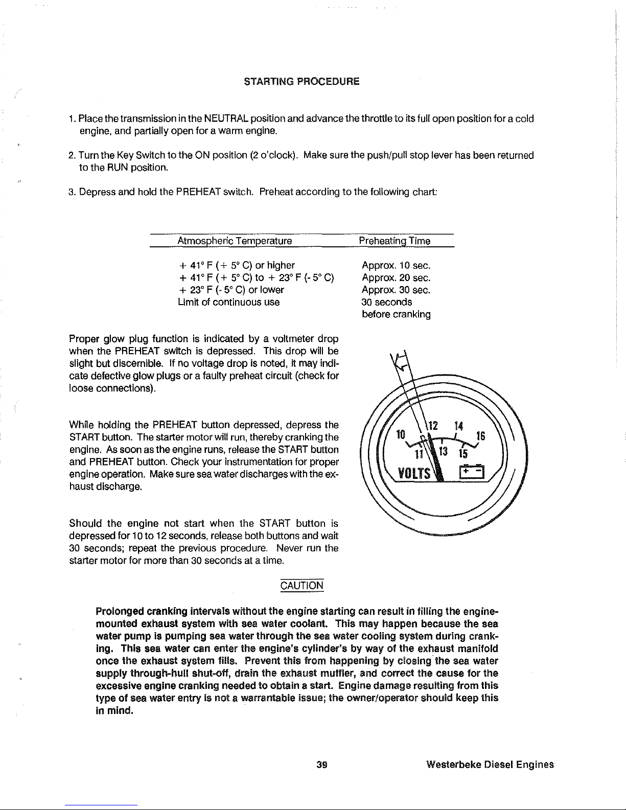
STARTING PROCEDURE
1.
Place the transmission in the NEUTRAL position and advance the throttle
to
its full open position for a cold
engine, and
partially open for a warm engine.
2. Turn the Key Switch to the ON position
(2
o'clock). Make sure the push/pull stop lever has been returned
to
the
RUN
position.
3. Depress and hold the PREHEAT switch. Preheat according
to
the following chart:
Atmospheric Temperature
+
41'
F
(+
5'
C)
or higher
+
41'
F
(+
5'
C)
to +
23' F (-
5'
C)
+
23' F (-
5'
C)
or lower
Limit of continuous use
Proper glow plug function
is
indicated
by
a voltmeter drop
when the
PREHEAT switch
is
depressed. This drop will
be
slight but discernible. If no voltage drop
is
noted, it may indi-
cate defective
glow
plugs
or
a faulty preheat circuit (check for
loose connections).
While holding the
PREHEAT button depressed, depress the
START
button. The starter motor will
run,
thereby cranking the
engine. As soon as the engine runs, release the
START
button
and
PREHEAT button. Check your instrumentation for proper
engine operation. Make sure sea water discharges with the exhaust discharge.
Should
the
engine not start when the START button is
depressed for
10
to
12 seconds, release both buttons and wait
30 seconds; repeat the previous procedure. Never run the
starter motor for more than
30 seconds at a time.
CAUTION
Preheating
Time
Approx.
10 sec.
Approx.
20
sec.
Approx.
30
sec.
30
seconds
before cranking
Prolonged cranking inlervals without
the
engine starting can result in filling
the
engine-
mounted
exhaust system
with
sea water coolant.
This
may
happen because
the
sea
water
pump
is
pumping
sea water
through
the
sea water
cooling
system
during
crank-
ing.
This
sea water
can
enter
the
engine's
cylinder's
by
way
01
the
exhaust manifold
once
the
exhaust system fills. Prevent
Ihis
from happening
by
closing
the
sea water
supply
through-hull
shut-oil,
drain
the
exhaust muffler, and correct
the
cause
for
the
excessive engine
cranking
needed 10 obtain a start. Engine damage resulting from
this
type
of
sea water entry
is
not a warrantable issue;
Ihe
owner/operator should keep
this
in mind.
39
Westerbeke Diesel Engines
Page 42

Once the engine starts, run
tt
at idle for a few minutes
to
warm up the engine and check instruments for
proper oil pressure and battery charging voltage. Never attempt
to
engage the starter while the engine is
running.
NOTE: Some unstable running may occur in a cold engine, but this condition should smooth
out as the operating temperature of 130 -
1500 F (55 - 66
0
C)
is
reached.
Westerbeke
Diesel
Engines
40
Page 43

STOPPING PROCEDURES
A manual pull type stop control (tee handle
or
knob) is provided
by
the installer in a location close
to
the
engine's controls. Know the location
of
this control before attempting
to
start the engine. To stop the en-
gine, pull out on this tee handle
or
knob fully and hold it out until the engine comes
to
a complete stop. Push
back on this control
to
return it
to
the engine run position otherwise the engine will not restart.
With the engine stopped, turn the Key
Switch
to
the OFF position
(12
o'clock). If the Key Switch
is
left ON,
the battery will discharge. The alarm buzzer will sound in the Admirals Panel but not
in
the Captains Panel
should the Key Switch be left ON. The best method
of
preventing the battery from discharge
is
to
remove
the key from the Key
Switch after stopping the engine.
CAUTION
DO
NOT attempt
to
shutdown the engine
by
turning the Key Switch OFF. The Key Switch
only
provides power
to
the instrument panel: the engine will continue running even if the Key
Switch
is
turned OFF.
(An
optional key shut-off package
is
available, however. This option allows the operator
to
shut-off the en-
gine
by
turning the Key Switch OFF which turns OFF an electrically run Fuel Run Solenoid. This electrical
shut-off option is installed at the factory upon the specffic request/order
of
the purchaser.)
Engine
Break-In
Procedures
Although your engine has experienced a minimum of one hour
of
test operations to make sure accurate as-
sembly procedures were followed and that the engine operated properly, a break-in time
is
required. The
service
life of your engine is dependent upon
how
the engine
is
operated and serviced during its initial hours
of use.
Your new engine requires approximately
50
hours of initial conditioning operation
to
break in each moving
part in order
to
maximize the performance and service life
of
the engine. Perform this conditioning careful-
ly,
keeping in mind the following:
1.
Start the engine according
to
the "STARTING PROCEDURE" section found on page 39; run the engine
at fast
idle while checking that all systems (sea water pump, oil pressure, battery charging) are function-
ing.
2.
Allow the engine
to
warm up (preferably
by
running at fast idle) until the water temperature gauge moves
into the
130-140° F range.
3.
While using the vessel, run the engine at varying engine speeds for the first 25 hours.
4.
Avoid rapid acceleration, especially with a cold engine.
5.
Use caution not
to
overload the engine. The presence of a gray or black exhaust, and the inability
of
the engine
to
reach its full rated speed, are signs
of
an overload (that
is,
operating the engine with a
propeller that
is
too large).
6.
During the next 25 hours, the engine may be operated at varying engine speeds, with short runs at full
rated speed. Avoid idling the engine for prolonged periods
of
time.
41
Westerbeke Diesel Engines
Page 44
Breaking-in a
new
engine basically involves seating the piston rings to the cylinder walls.
This
cannot
be
ac-
complished by long periods of running at Idle, nor by early running
at
full
speed.
Idle running may glaze the cylinder
walls,
resulting
in
excessive
oil
consumption
and
smoky operation.
Ex-
cessive speed or heavy overloading, especially with a cold
engine,
may
cause
scoring of the cylinder
walls,
producing similar results.
As
indicated above, operate the engine
in
moderation during the 50-hour break-in period.
(On
one
hand
don't baby the
engine,
but
on
the other
hand,
however, don't abuse
it.)
Starting Under Normal Conditions
Follow the procedure below for normal starting of the engine:
1.
Check the engine
and
transmission lubricant levels
and
fill,
if necessary.
2.
Make sure there
is
sufficient
fuel
on
board.
Keep
fuel
tank(s)
as
full
as
possible. Check the
fuel
filters
and water separators for the presence of contaminants and/or water.
Drain
and
clean them
as
needed.
3.
Check the coolant
level
in
the plastic recovery tank.
Add
coolant solution
as
needed.
NOTE:
Excessive loss of coolant from the plastic recovery tank indicates a cooling system
leak.
Check the entire cooling system
and
pressurize the system to locate the
leak.
In
cases
of excessive coolant
loss, the system must
be
refilled
as
outlined under the
"PREPARATION
FOR
STARTING"
section of this
manual,
page
33.
4.
Check for oil
and
fuel
leaks,
particularly H signs of such leaks are found on the bottom of the engine or
below the engine.
Start the engine
in
accordance with the
"STARTING
PROCEDURE"
instructions found on page
39,
and
allow
the engine's operating temperature to reach
140
- 150' F before operating the engine underway.
Starting Under Cold Conditions
Under extremely
cold temperatures, the following conditions
can
occur. Follow the instructions listed below
when operating your engine
in
cold weather.
LUBRICATING
OIL
TURNS
VISCOUS -Make
certain that the lubricating oil
used
conforms with the ratings
for the prevailing atmospheric temperature.
Refer
to the
"LUBRICATION
SYSTEM"
section of this manual,
page
60
for
an
atmospheric/oil viscosity specification table.
VOLTAGE
ACROSS
THE
BATIERY
TERMINALS
DROPS -Make
certain that the battery
is
fully charged to
minimize
voltage drop across the battery terminals.
THE
TEMPERATURE
OFTHE
INTAKE
AIR
IS
LOW
AND
THE
COMPRESSION
TEMPERATURE
DOES
NOT
RISE
ENOUGH
-Allow the glow plugs to operate sufficiently to
aid
in
starting during the preheat period when-
ever the temperature of the intake air
is
low
and
when
the compression temperature does not
rise
enough.
Refer
to the preheat chart found
in
the
"STARTING
PROCEDURE"
section, page
39.
Westerbeke Diesel Engines 42
Page 45

FUEL SYSTEM
Diesel Fuel
Use
No.2
diesel fuel with a cetane rating
of
45
or
higher. Never use kerosene
or
home heating oil since
these fuels
do
not have the same lubricating properties
as
No.2
diesel fuel.
In cold weather particularly, water vapor
is
produced by condensation when air is present
in
the fuel tank.
Keep fuel tank(s) full and completely free of dirt and water.
Fuel Fillers
A primary
fuel filter
of
the water entrapment
type must be installed between the
fuel
tank and the engine. A primary fuel filter,
shown here, is available from your local
Westerbeke representative
or
your boat-
builder. This filter, adapted
for
boatbuilder
use, comes complete with fittings for either
hose or metal tubing. Mount
tt
in an acces-
sible place, inspect
tt
often and drain off
water accumulation frequently.
If a water trap type filter
is
not installed be-
tween
the
fuel
tank
and
the
enginemounted fuel system, any water in the fuel
system will tend
to
lay in the bottom
of
the
electric
lift pump. Internal metal parts of the
lift pump will rust. Particles will pass on
to
filters and eventually
to
the injection pump
and injectors
wtth damaging results and
the
possibility
of
expensive
repairs.
Remember, water damage
to
the fuel sys-
tem
is
not covered under the Westerbeke
warranty.
In addttion, any gasoline in the fuel system
HOSE
FITTING
XNSTRLLRTION
INSTRUCTIONS
L
BOLT
SEDI"EHT/fA1ER
TRAP
SHURELl
TO
RII
ACCESSIBLE
STRUCTUII£
SO
POSIIIOIiED
TIIU
1\
RECEI'TICL[
Tn
CATCH
DRAINAGE
CAM
BE
PUtED
IIMOER
II.
2.
IF
FUEL
IS
TO
BE
I'IIIED
nTH
COPPER,
011
BUMD'
IUBUS,
USE
NUTS
AMD
F[UULES
PRaUIDED.
BE
SUlIE
THE
HIllING
PROJECTS
114
IlCH
THROUIIH
THE
FERRULE
BEFIU[
TlSHTEMING
TNE
HUt.
3.
If
FUEl
IS
Til
BE
PIPU
mil
HOSE,
USE
THE
TMD
BRASS
BARBED
FIITIIiSS
AWO
WASHERS
SUPPLIED,
SE
CERIAU
IHAI
THE
HOSE
SElEtlED
HAS
IIUGOMAL
BRAID
INSERTED
no
CLUG
ON
lHE
BARB),
TIIRT
IT
IS
N£DPREIIE
LINED,
AMO
THRT
IT
IS
~g!l
APPRDIl[D.
4.
IF
~AT£R
IS
!lRESEMT
IN
THE
FUEL,
IT
Ull
ClltlECT
StD~tV
III
THE
BOTTCH
or
TH!
SEllINEMTER.
1I11EN
TilE
REO
HOAT
RIMS
UERCHU
THE
ORAIN
LIIiE
011
THE
PLWIC
BOWL.
l005EK
THE
BonUM
DIIAU
PlUS
UNTIL
ALL
~ArEA
RUNS
OUT.
6. lUHlEN
ORRIN
PLUI
SECURELY
SO
~O
An
CAW
ENlER
THE
SUrE".
6. [HUGI2E
THE
rUEL
PUMP
TO
RErILL
TilE
901fL.
will damage the engine's fuel injection pump assembly and injectors, as gasoline does not have the same
lubricating qualtties as diesel fuel.
Although most boatbuilders supply a water trap/filter, some
do
not. Westerbeke offers a sedimentary/water
trap/filter as an optional extra at moderate cost. The filter
is
supplied with fittings
for
either hose
or
metal
tubing fuel lines.
43
Westerbeke Diesel Engines
Page 46
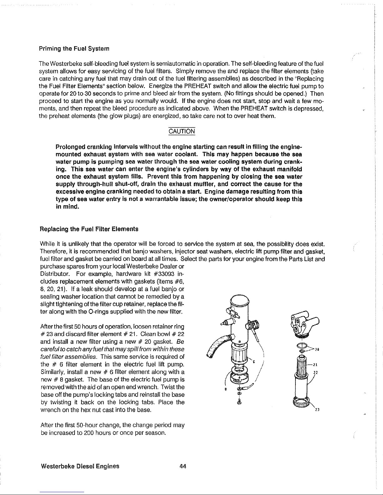
Priming
the
Fuel System
The Westerbeke self-bleeding fuel system
is
semiautomatic in operation. The self-bleeding feature of the fuel
system allows for easy servicing
01
the fuel filters. Simply remove the and replace the filter elements (take
care in catching any fuel that may drain out
01
the fuel filtering assemblies) as described
In
the "Replacing
the
Fuel
Filter Elements" section below. Energize the PREHEAT switch and allow the electric fuel pump to
operate for
20
to
30
seconds to prime and bleed air from the system. (No fittings should be opened.) Then
proceed
to
start the engine as you normally would. If the engine does not start, stop and wait a few mo-
ments, and then repeat the bleed procedure as indicated above. When the PREHEAT
SWITch
is depressed,
the preheat elements (the glow plugs) are energized, so take care not
to
over heat them.
CAUTION
Prolonged
cranking
intervals
without
the
engine starting can result in
filling
the
engine-
mounted
exhaust
system
with
sea water coolant.
This
may
happen
because
the
sea
water
pump
is
pumping
sea water
through
the
sea water
cooling
system
during
crank-
ing.
This
sea water can enter
the
engine's cylinders
by
way
01
the
exhaust
manifold
once
the
exhaust
system
Iills. Prevent
this
irom
happening
by
closing
the
sea water
supply
through-hull
shut-off,
drain
the
exhaust muffler, and
correct
the
cause
for
the
excessive
engine
cranking
needed
to
obtain
II
slart.
Engine
damage
resulting
from
this
type
of
sea water
entry
is
nol
II
warrantable issue;
the
owner/operator
should
keep
this
in
mind.
Replacing
the
Fuel
Filler
Elements
While it
is
unlikely that the operator will be forced to service the system at
sea,
the possibility does exist.
Therefore, it
is
recommended that banjo washers, injector seat washers, electric lift pump filter and gasket,
fuel filter and gasket be carried on board at
all
times. Select the parts for your engine from the Parts List and
purchase spares from your
local Westerbeke Dealer
or
Distributor. For example, hardware kit #33093 includes replacement
elements with gaskets (items
#6,
8,
20,
21). If a leak should develop at a fuel banjo or
sealing washer location that cannot be remedied
by
a
slight tightening of the filter cup retainer, replace the fil-
ter along with the O-rings supplied with the new filter.
After the first
50
hours
of
operation, loosen retainer ring
#
23
and discard filter element #
21.
Clean bowl #
22
and install a new filter using a new #
20
gasket. Be
careful
to
catch any fuel that
may
spill
from
within
these
fuel filter assemblies. This same service
is
required
of
the # 6 filter element in the electric fuel lift pump.
Similarly, install a new # 6 filter element along with a
new # 8 gasket. The base of the electric fuel pump
is
removed with the aid
of
an open end wrench. Twist the
base off the pump's locking tabs and reinstall the base
by twisting it back on the locking tabs.
Place the
wrench on the hex nut cast into the base.
After the first
50-hour change, the change period may
be increased to
200 hours or once per season.
Westerbeke
Diesel Engines 44
@?
,
\
I
/
~
I
Page 47

Fuel
Injection
Pump
The illustration below shows the W
356
THREE's fuel system. The W 386 FOUR and W 426 FOUR's fuel
system differ in that they have an additional fuel Injector and injector pump plunger. The fuel injection pump,
located to the right,
is
one
of
the most important components of the diesel engine and, therefore, calls for
the utmost caution in
handling. Furthermore, the fuel injection pump has been thoroughly bench-tested and
should not be tampered with.
Idle speed and timing adjustment are the only adjustments the servicing dealer can perform on the injection
pump.
Other types
of
adjustments
or
repairs must be performed by a qualified injection service shop.
ElECTRIC
FUEL
LIFT
PUMP
FUEL
INJECTORS
FUEL
PUMP
FILTER
Fuel Injection System
INJECTION
PUMP
OIL
FILTER
THROTTLE
OIL
PUMP
To obtain long and satisfactory service from the injection pump, always use fuel which is free from impurities
and maintain a good filtration and water separation system between the fuel tank and engine.
Service this
system regularly: the injection pump it saves will be your own.
45
Westerbeke Diesel Engines
Page 48

ELECTRICAL SYSTEM
Engine
12-Volt DC
Control
Circuit
The Westerbeke 35B, 38B and 42B propulsion engines have a 12-Volt
DC
electrical control circuit, as shown
on the wiring diagrams which
follow on pages 48
to
51.
Refer to these diagrams when troubleshooting or
servicing electrical components on the engine.
.
CAUTION
To avoid damage
to
the battery charging circuit, never shut off the engine battery switch while
the engine
is
running.
Shut off the engine battery switch, however, to avoid electrical shorts when working on the
engine electrical circuit.
Battery
Specification
The minimum recommended capacity of the battery used in the engine's 12-Volt
DC
control circuit is 90 -
125 Ampere-hours (minimum).
CAUTION
When quick-charging the battery with an external charger, be sure to disconnect the battery
cables from the battery. Leaving the charging circuit connected while quick-charging
will
damage the alternator's diodes.
Alternator
CAUTION
When testing the alternator circuit (charging circuit),
do
not use a high-voltage tester such as
a megger; damaged diodes could result.
During high-speed operation of the engine,
do
not disconnect the positive terminal
of
the bat-
tery from the B terminal
of
the alternator, nor disconnect the negative terminal of the battery
from the ground.
When cleaning the engine with a steam cleaner, be careful to keep steam away from the
al-
ternator.
Refer
to
pages 48
to
51
for the
two
electrical system wiring schematics (one
is
used for the Captains panel
and the other for the Admirals Panel).
Westerbeke Diesel
Engines
46
Page 49

The charging system consists of an alternator with an internal voltage regulator, an engine-mounted circuit
breaker, a battery and connecting wires.
Because
of
the use of IC's (integrated circuits), the electronic voltage regulator
is
very compact and
is
built
into the rear bracket of the alternator.
Charging
Voltage
Test
If you suspect that the alternator
is
not producing enough voltage
to
charge the engine's battery, perform
the
following voltage test.
Al
TERNATOR
135
n.
40
A.
50
Al
,-----/---€,i\l--\
- -
Interconnections for Charging Voltage Test
I
I
I
1.
Using a voltmeter, connect the voltmeter's red wire clip
to
the B output terminal on the alternator. Refer
to
the schematic shown above.
2.
Connect the other wire clip
to
a ground on the engine.
3.
Start the engine and increase the engine's speed to 2000 rpm. Now record the reading given
by
the
voltmeter.
The voltage reading
for
a properly operating alternator should be between 13.5
to
14.5 volts. If your alter-
nator
is
over
or
under charging, have it replaced or rebuilt by a reliable service shop.
Note: Before removing the alternator for repair, make sure 12-Volts excitation
is
present at the
R terminal should the above test show only battery voltage at the B output
terminal.
47
Westerbeke Diesel Engines
Page 50

Captains Panel
DC
Control Circuit Wiring Diagram #36467
page 1 of 2
~"
GLOW>'LUGS
[l'!".O~6
t::'I. _il'
OfP£"D'~~
01<
\:1llP'
NU
..
aEI<OI'
~
,'"iNDERS'
~
CIRCUIT
•
'0'
WATER
TEMP
SENDER
-~;
•.
lo<'TIONAL
"'T><
,,,ST.
PA"tU
DIAGRAM
"'ATER
TEMP.
SWITCH
;l{*"''''''
r
"
PflEHEh
1
'---+-----1-,
SOLENOtO
~
';~~
G
£j
~
'
'i'l,IJ,i!
\
'''i
.'f!'
,""-
·~l·Q
.Q
.~
.'
,
i
I
,--
I
!
,
o
.'
".-1---+---+
(,,-rio'll
"
Q
0
Q
,
J1
,
,
0
.'
.-
;
I .
<'SO""
"8
OP~
----+fT
-:---ti':r
+---
'.
cuE
~
0
:~:,,~,
~:
~
STIlRT
I'L.Se>
Ifl~i
TEST SwiTCH
,r
'-""'L
I['r---,
~
~A~pl
~.
'14 " I
~';~I
.
'",,,
15-
I
.-
W
T.
48
I
,
~E"
LA~tPt
£!,
,
"""'" I
PREHEAT
',4s,Ur
S"ITCH
"18
Bl<
.,~
Gc'
I
~
-
1--
- -
ro-~
,/
,-
-
I)
\~
TACHOMETER
I
I
I
I
I I
~------------------------------~
"BBL"
"oSL'
Westerbeke Diesel Engines
48
Page 51

Captains Panel
DC
Control Circuit Wiring Diagram #36467
page 2 of 2
r:;:
'2VOC
SCHEMATIC
5TIIOIT
SW'TCH
,
, C.B
)
IQA
,----:---"1;"
hi
"
"
" " " "
"
!
X·
"
,,!
~
n
"
.~
n
:;
'"
,
"
"
Go
ALARM
START'
I,TURN
KEY
TO
ON
POSITION.
THE
ALARt~
WILL
SOUND,OIL
PRESSURE
.'\NO
BATTERY
CHARGE
INQICATORS
HILL
LIGHT,
2.PUSH
pqEHEAT
SWITCH
FOR.
15
TO
50
SECONDS AS
REQUIRED,
ALARM 'WILL STOP,
3,WHILE
CONTINUING
TO
PUSH
PREHEAT
SWITCH,PUSH
THE
START
SWITCH
ALSO.
I-/rlEN
THE
ENGINE
STAins
gElEASE
THE
START
SWITCH ONLY.
lWHEN
THE OIL
PRESSURE
INDICATOR
LAMP
GOEs
our
RELEASE
THE
PREHEAT
SWITCH,
STOP:
TURN THE KEY
TO
THE
OFF
POSITION.
~
I.
THIS
PRODUCT IS PROTECTED
a.,.
A
MANUAL
RESET
CIRCUIT
BREAKER
LOCATED
,"EAR.
THE
STARTER,EXCESSIVE
CURRENT
DRAIN
WILL
CAUSE THE BREAKER
TO
7RIf'
AND THE
ENGINE
WILL
SHUT
OO\iN.
THE
BUILDER./eWNE>:!
MUST
8E
SURE
THAT
THE
ICiSTHUMENT
PANEl,WIRING
AND ENGINE
>'IRE
INSTALLED
TO
PREVENT
CONTACT BETWEE\J
ELECTRICAL
DEVICES AND
SALTWATER.
2.AN
ON-OFF
SWITCH
SHOULD
BE
INSTALLEO
BET'<IEEN THE BATTEA'!'
AND
STARTER
TO
DISCONNECT THE BATTER'!' IN
AN
EMERGENCY AND WHEN
LEAVING
THE EOAT. A SWITCH
WITH
A
CONTI"lUOUS
RATING OF
17';AMPS
AT
12VDC
WILL,SERVE
THIS
FUNCTION
THIS
SWITCH SHOULD NOT 8E USED
TO
MAKE
0R
BREAK
TH£
CIRCUIT.
.
.:.
PINK WIRE
AT
PLUG
2.
IS
UNUSEf'
AND
SHOULD
BE
ItISULATEiJ.
49
Westerbeke Diesel Engines
Page 52

Admirals Panel
DC
Control Circuil Wiring Diagram #36844
page
1012
ALTERNATOR
~
________________________
~C;'-'~'~O~R~E=D'-
___
,r--t?
__
~:~
,cAl
~J:~Fs
~;C'RCUIT/_~n_~~_A;~:_:_R
__
+
__
r_~_~_;_C:
___
",--,,:.:c:.c...'-.cc.
__
Ji'l,,_,IF,,_
,;
'I
L,
PREHEAT
SOLENOID
" :
"EAKER
I ' "' ."
LT,
BLUE
1
'It
r-;[7""'j
I'
I '
wi
D_~'
n
I~,
M1
#14LT.BLUe
~I
."RED
~,'lil I (~~'
~:~SS=URE
--H-t-r-[
,_-
__
)
.t---Jt~-.
--§:...jT'
rPJ
-+---1
--+-
IUr::~:~R:~DDELSI
_IJ[_-:~
-:U~~D'D
,
~
Ic
...
OIL
~
~,3
1
{USED
IN
SOME
~~~E2
~[,
;;0
c';'
I I
rl
~
:::~i~RE
!
~.'I:
~.I,;.I,
~I~=
, CIRCUIT J 20 A
1m
i
GROUND
1
:'
.
C I
BREAKER
~
TO
ENGINE
STARTER I
~
BLOCK I
I
~
GRO~NO
TO
NEUTRAL I
PUMP
1
ENGINE
BLOCK
ill
SAFETY SWITCH I '
t : (USED ON SOME
~
r -
L'~M~D~D~E=~~I
__
-i+-r~t1,
""BA"'IT="""Y"I
12VDC _
)1
D
I~
- -1.-;'
z
<
"
"
;;
52 6
w,
;1
"'
'It!
C
!I
>
i
<
il
"
,
D
0,
1
°1
FJE3l
o
"c,,,
I
c::
111'
-'
1_
j}J
Ill,
[I
>-16
1
~lm,i3
3::
'"
J ::::
:::':::::::i~,~,:::t~
\\/
~
~!
'It~
'It!"'!
'It:""
",1'1>
.
RTi!
I
U
~1l1)~,i
~J,
~
\\jJ)/
F)
~
ALARM
BUZZER
I
I
,-'
-+------;--,
I : I I
OIL
PRESS
-WATERTE~
T
--
--il-I-
I
GAUGE GAUGE I I
-NI
~,
I
;1
1
-e
>'21~E,>
~_
II
I"'~YEL
I I
,'''"",
~
I
~
I I
! I
I~"GRN!
\,
·cJ~G>t'._.
G.l
I I
I"
:0
",'
"14GRN.
I
'V_~
~-,---,-".--c/,:.,c,o:~
I
W:::
I
Z~
<i>~
! \ /
lJiTART
PREHEAT
KEY
SWITCH
~
S,WITCH
SWITCH
VOLTMETER
.~
(~
~'
..
~oel'.
- I
Westerbeke Diesel Engines
50
Page 53

Admirals Panel
DC
Control Circuit Wiring Diagram #36844
page 2 of 2
I
NEUTRA
sw.
T
,,1
"
1"1\
~I,
1=1
W
1KEY
I
"r
sw
I
. I
~I
~-
I
PREHEAT
$W,
NOTE:
PI
1'1
SCHEMATIC DIAGRAM
e,o
p
•
ALARM
1.
THIS
PRODUCT
IS
PROTECTED
BY A
MANUAL
RESET
CIRCUIT
BREAKER
LOCATED
NEAR
THE
STARTER.
EXCESSIVE
CURRENT
DRAIN
WILL
CAUSE
THE
BREAKER
TO
TRIP
AND
THE
ENGINE
WILL
SHUT DOWN. THE BUILDER/OWNER MUST BE SURE THAT THE INSTRUMENT PANEL,
WIRING,
AND
ENGINE
ARE
INSTALLED
TO
PREVENT CONTACT BETWEEN ELECTRICAL
DEVICES AND SALT WATER.
2.
AN
ON~OFF
SWITCH SHOULD BE INSTALLED BETWEEN THE BATTERY AND STARTER TO 015-
CDNNECTTHE
BATTERY
IN
AN EMEAGENCY,ANO WHEN LEAVING THE BOAT. A SWITCH WITH
A
CONTINUOUS
RATING OF 175
AMPS
AT
12
VOLTS
DC
WILL
SERVE THIS
FUNCTION,
THIS
SWITCH
SHOULD
NOT
BE
useD
TO
MAKE
OR
BREAK
THE
CIRCUIT.
3.
THE
GRAY WIRE
AT
PLUG
#21S
UNUSED
AND
SHOULD BE
INSULATED.
51
Westerbeke Diesel Engines
Page 54

COOLING SYSTEM
Description
Westerbeke marine diesel engines are designed and equipped for fresh water cooling. Heat produced in
the engine by combustion and friction is transferred
to
fresh water which circulates throughout the engine.
This circulating fresh water cools the engine
block and its internal moving parts. The heat is transferred ex-
ternally from the fresh water
to
sea water
by
means
of
a heat exchanger, similar
in
function
to
an automo-
tive radiator.
Sea water flows through the tubes of the heat exchanger while fresh water flows around the
tubes; engine heat transferred
to
the fresh water is conducted through the tube walls
to
the sea water which
is then pumped into the exhaust system where
finally it is discharged overboard. In other words, the engine
is cooled
by
fresh water, the fresh water is cooled
by
sea water, and the sea water carries the transferred
heat over the side through the exhaust system. The fresh water and sea water circuits are independent of
each other. Using
only fresh water within the engine allows the cooling water passages
to
stay clean and
free from harmful deposits. The two independent circuits and their components are discussed in the
follow-
ing paragraphs.
Fresh
Water
Circuit
NOTE: Refer
to
paragraphs A and B
in
this section for the recommended antifreeze and water
mixture
to
be used as the fresh water coolant, and for information on filling the fresh water
system.
Fresh water is pumped through the engine
by
a belt-driven circulating pump, absorbing heat from the en-
gine. The fresh water coolant circulates through the engine's block absorbing heat, then passes through
the thermostat into the exhaust manifold,
to
the heat exchanger where it is cooled, and then is returned
to
the engine block through the suction side of the fresh water circulating pump. When the engine is started
cold, external fresh water flow is prevented
by
the closed thermostat (although some fresh water flow is
bypassed around the thermostat
to
prevent exhaust manifold from overheating). As the engine warms up,
the thermostat gradually opens,
allowing full flow of the engine's fresh water coolant
to
flow unrestricted
to
the external portion of the cooling system.
A.
Fresh Water Coolant (Antifreeze) Mixture.
A freshwater and antifreeze mixture
should be used year-round in the cooling system. Water, when
it
freezes,
expands sufficiently
to
split the heat exchanger and crack the engine block. A water/antWreeze mixture
of
proper concentration will prevent freezing (see page
53
for an antifreeze/water mixture chart).
Use soft water with few impurities, such as tap water (potable water)
or
rainwater. Never use hard
or
foul
water. Use
of
hard water
or
water containing impurities will lead
to
the collection of scale in the engine and
heat exchanger which
will reduce the cooling system's efficiency.
Antifreeze of
poor
quality
or
without rust inhibitors will cause corrosion within the cooling system. Always
use antrrreeze which is compatible wah aluminum cooling system components and is made by a reliable
manufacturer. Never mix different brands
of
antifreeze.
Make sure that the
cooling system
of
the engine is well cleaned before adding antifreeze. Recommended
antifreeze for year round use is
ZEREX
or
PRESTONE with rust inhiMors.
In
order
to
control the concentration of the mixture, mix the antifreeze and freshwater thoroughly before ad-
ding it
to
the cooling system.
Westerbeke Diesel Engines 52
Page 55

Antifreeze
Concentration
Freezing
Temperature
ANTIFREEZE
CONCENTRATION DATA
%
13
23
30
35 45
50
60
° F 23 14 5 - 4 -22 - 40 - 58
("
C) (-5)
(-10)
(-15) (-20) (-30) (- 40) (-50)
NOTE:
An
antifreeze concentration should be selected on the basis
of
a temperature which
is about
10° F
(5°
C)
lower than the actual atmospheric temperature expected.
B.
Filling the Fresh Water System
A coolant recovery tank kit
is
supplied wtth each Westerbeke diesel engine. The purpose
of
this recovery
tank is
to
allow
lor
engine coolant expansion and contraction, during engine operation, without the loss of
coolant and without introducing air into the
cooling system.
This coolant recovery tank should be
installed at,
or
above, engine manifold level, in a location where it can
be easily monitored and where coolant can be easily added if needed (see the figure below). A stainless
steel mounting bracket
is
supplied with each kit along with a 30-inch length
of
clear plastic hose and clamps
to
connect the hose between the engine's manifold fitting
to
the hose spud on the base
of
the recovery tank.
FUNCTION
OF
MANIFOLD
PRESSURE
CAP
From
Coolant Tank
COOLANT RETRACTION
to Coolant
Tank
COOLANT EXPANSION
Coolant from the engine, when heated during engine operation, will expand, lifting the spring-loaded manifold
pressure cap, and enter the recovery tank by way
of
the hose connecting the recovery tank
to
the manifold.
When the engine
is
shut
down
and cools, a small check valve in the pressure cap
is
opened by the contrac-
tion
olthe
engine coolant, allowing some of the coolant in the recovery tank
to
be drawn back into the engine's
cooling system, Iree of air and without loss. Periodically check that the passage (A) between the
90°
litting
on the
manifold and the filler neck
in
the manifold
is
clear so coolant can flow
in
either direction.
53
Westerbeke Diesel Engines
Page 56

COOLANT RECOIIERY TA"I<
:
'1
: i: '
\"
'I'
\
. ,
,'\
. "
.,
1\'\
"I
.'\'
'\1
1
'
, I ' 1 I
.
\"
(,
!
, ,
Coolant Recovery Tank, Recommended Installation
Fill the fresh water system as follows:
1.
Remove the pressure cap from the manifold.
2.
Pour a clean, antifreeze mixture into the manifold and allow enough time for the coolant
to
fill the fresh
water cooling system.
3.
Start the engine and allow
it
to come up
to
its operating temperature. Monitor the coolant in the manifold
and add antifreeze coolant as air is expelled.
Once all air
is
expelled from the system, fill the manifold to
the filler neck and install the pressure cap.
4.
Remove the plastic cap from the plastic coolant recovery tank and fill the tank with coolant halfway between the ADD mark and the
MAX mark. Replace the plastic cap.
5.
Run the engine and observe the coolant's expansion flow into the plastic recovery tank.
6.
Check for leaks between the pressure cap/filler neck and then plastic recovery tank. Stop the engine and
allow
it
to
cool. Coolant should be drawn back into the cooling system
as
the engine's temperature comes
down.
7.
Add coolant
to
the recovery tank, as required, to top off the fresh water coolant system.
Thermostat
Generally, thermostats are of
two
types. One
is
simply a choking device which opens and closes as the
engine's temperature rises and falls. The second type has a bypass mechanism. Usually this
is
a disc on
the bottom of the thermostat which moves downward
to
close off an internal bypass passage within the
head. Since 1980, each type of thermostat has a hole punched through
it.
The hole
is
a bypass
to
prevent
the exhaust manifold from overheating during the engine's warm-up. Replacement thermostats must have
this design characteristic.
Westerbeke
Diesel
Engines
54
Page 57

Sea
Waler
Circuit
The sea water flow
is
created by a bel!driven, positive displacement, neoprene
impeller pump, The pump draws sea
water directly from the ocean through the
sea
cock
and sea water strainer and pas-
ses the water
to
the heat exchanger's sea
water
inlet. The sea water passes through
the heat exchanger's lUbes, from which
heat
from the fresh water system
is
ab-
sorbed, and then the sea water
is
dis-
charged
from
the
cooling
system
overboard through the water-injected wet
exhaust system, Be sure to clean zinc
debris from the area inside of the heat exchanger where the zinc anode
is
posi-
tioned,
. :.;
;
}-
'"
~
::~
NEW
ANODE
i
.....
CLEAN
OR
REPLACE
REPLACE
REPLACE
Zinc Anode Condttions
A zinc anode,
or
pencil,
is
located in the sea water cooling circuit within the heat exchanger, The purpose
of the zinc anode
is
to
sacrifice itsell
to
electrolysis action taking place
in
the sea water cooling circuit, there-
by
reducing the effects of electrolysis on other components
of
the system, The condition of the zinc anode
should be checked monthly and the anode cleaned or replaced as required, Spare anodes should be carried on board,
Sea Water
Pump
The sea water pump
is
a self-priming, gear-driven rotary pump with a non-ferrous housing and a neoprene
impeller. The impeller has flexible vanes which wipe against a curved cam plate within the impeller housing,
producing the pumping action,
On no account should this pump be run dry, There should always be a spare
impeller and
impeller cover gasket aboard (an impeller kit), Sea water failures
occur
when lubricant (sea
water) is not present.
Such failures are not warrantable and the operator's are cautioned
to
make sure sea
waler flow is present at start-up.
Alternator
and
Waler
Pump
Drive Bel! Tension
IWARNING!
Never attempt
to
adjust the drive belt's tension while the engine
is
in operation,
CAUTION
Excessive alternator and water pump drive belt tension can cause rapid wear of the belt and
reduce the service
lile of the fresh water pump and alternator shaft bearings, Excessive slack
or the presence
01
oil on the belt can cause belt slipping, resulting
in
high operating tempera-
ture, as well as insufficient alternator output.
55
Weslerbeke Diesel Engines
Page 58
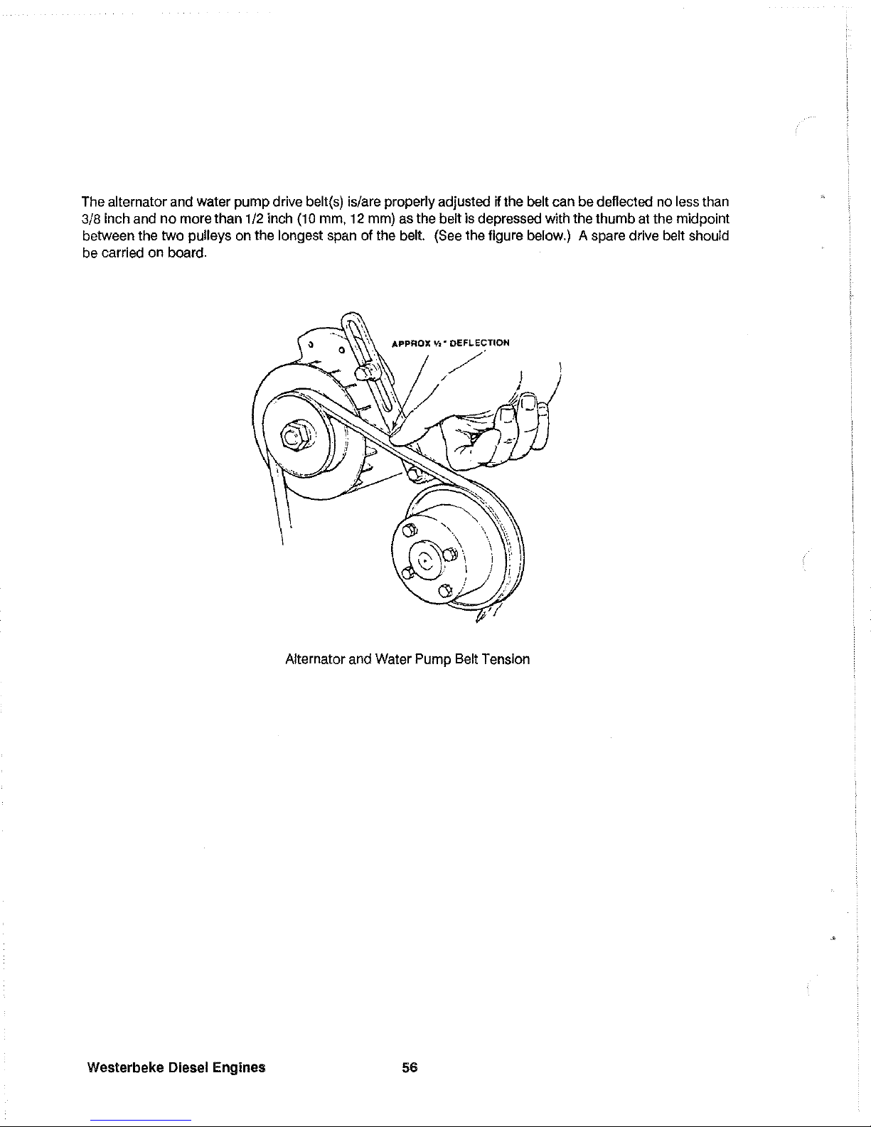
The alternator and water
pump
drive belt(s) is/are properly adjusted W the belt can be deflected no less than
3/8 inch and
no
more than 1/2 inch
(10
mm, 12 mm) as the belt is depressed with the thumb at the midpoint
between the two
pulleys on the longest span of the belt. (See the figure below.) A spare drive belt should
be carried
on
board.
Alternator and Water Pump Selt Tension
Westerbeke
Diesel
Engines
56
Page 59

Illustrated below
is
a typical Westerbeke engine's cooling system. Both fresh water and
sea
water flow
through their independent
cooling circutts. Refer to your engine's Parts List for part numbers and part
descriptions
if you need to order cooling system parts for your engine.
NOTE: When the remote expansion tank #24177 is used, the plastic coolant recovery tank
should
be
removed and discarded and its connection point on the exhaust manifold plugged
with a 1/8
NPT
fitting.
COOLANT
RECOVERY
TANK
HEAT
WATER
INJECTED
ELBOW
CONTROllER
EXHAUST
OVERHEAT
ALARM
WATER
FRESH
WATER
PUMP
f
IMCOMING
SEA
VATER
Typical Cooling System
57
Westerbeke Diesel Engines
Page 60

Domestic
Hoi
Water
All
engine covered in this manual are
equipped with a domestic hot water con-
nection.
If the owner/operator wishes
to
connect a hot water heater, remove the
bypass hose and connect a heater as
described
in
the instructions presented
below.
General:
With the bypass hose (Part #
30962) removed, there remain
two
con-
necting points A and
e for hoses
to
run to
and from the water heater. These connec-
tions assure a
How
of hot water through
the heater at
all
times but
do
not effect the
flow
of
coolant through the engine.
Flow Controller
Installation:
The heater should be mounted conveniently either in a high or low position
in
relation to the
engine so that the connecting hoses from the heater to the engine can run
in
a reasonably direct line without
any
loops which might trap air. Connection point A on the Flow Control housing should connect to the lower
of
the
two
connections on the water heater while the upper connection on the heater returns
to
connection
e,
nearest to the heat exchanger.
REMOVE
RETURN
BEND
FROM
ENGINE
fLOW
CONTROLLER
PRESSURE
CAP
IS
RATED
LOWER
THRN
MANIFOLD
CAP
HEATER
COILS
BELOW
PRESSURE
CAP
ON
ENGINE
MANIFOLD
REMOTE
EXPRNSION
TRNK
HEATER
COILS
ABOVE
PRESSURE
CRP
ON
ENGINE
MANIFOLD
A
AIR
BLEED
PET
COCK
HEATER
BELOW
ENGINE
HEATER
ABOVE
ENGINE
The illustrations shown above are Flow Control designs that have been adapted to operate with the single
pass manifolds installed on the W 358, the W 388, and the W 428 engines.
Westerbeke
Diesel
Engines
58
Page 61

Hoses should rise continuously from their low point at the heater
to
the engine so that trapped air will rise
naturally from the heater to the engine. If trapped air
is
able rise
to
the heater, then an air bleed petcock must
be
installed at the higher fitting on the heater for bleeding air while filling the system. Avoid loops in hose
runs which will trap air.
Note:
If any portion
of
the heating circuit rises above the engine's own pressure cap, then a
pressurized (aluminum) remote expansion tank
must be installed in the circuit
to
become the
highest point. The remote expansion tank's part number
is
24177. Install the remote expan-
sion tank in a convenient location such as in a sail locker so the fresh water coolant level can
easily
be c hec ked.
The cap on the engine mounted expansion tank should not be opened once the remote system
is
installed
and filled.
The hose connection from the heater
to
the remote expansion tank should be routed and supported so as
to
rise continuously from the heater to the lank, enabling any air in the system to rise.
Refer
to
the illustrations on the previous page.
59 Westerbeke Diesel Engines
Page 62

LUBRICATION SYSTEM
Engine
Oil
For engine lubrication, use lubricating oil designated for diesel service. These oils are classified according
to the
API
specifications into service grades
CA, CB,
CC and CD. The use
of
CC
or
higher
(CD)
grades,
made
by
well-known manufacturers
is
recommended. The oil selected should be used thereafter.
Engine
Oil
Viscosity
(SAE
Number)
Use an oil having a viscosity best suited
to
the atmospheric temperature. Use
of
an all-season oil
SAE
10W-
30
with minimum viscosity change under different temperatures
is
suggested.
Atmospheric Temperature
68'
F (20'
C)
or
higher
41'
F (5'
C)
-
68'
F (20'
C)
41'
F(5'
C)
-
or
lower
Viscosity
SAE
30 or 10W-30
SAE
20 or 10W-30
SAE
10W-30
NOTE:
Do not use an engine lubricating oil with an
SAE
number greater than
30
in the en-
gine.
Oil Pressure
The engine's oil pressure, during operation,
is
indicated by the oil pressure gauge on the Admirals Panel
(see page 37).
During normal operation, the oil pressure will range between 35 and 60 psi. At idle speed, the oil pressure
will range between
20 and 35 psi. At the time of cranking, the oil pressure will rise proportionately with speed.
NOTE: A newly started, cold engine can have an oil pressure reading upwards
of
60 psi. A
warmed engine can have an oil pressure reading as
low
as
35
psi. These readings will vary
depending upon the speed at which the engine is running.
Westerbeke Diesel
Engines
60
Page 63

Engine
Oil
Change
(to
include
IiIter)
1.
Draining the Oil Sump
Remove the oil drain hose from its attachment brack-
et and lower it into a container and allow the oil
to
drain,
or
attach a
pump
to
the end of the drain hose
and
pump
the old oil out. Make sure the oil drain hose
is properly secured in its holder after all of the old oil
has been drained.
Always observe the old oil as it is removed. A yellow/gray emulsion indicates the presence of water
in
the oil. Although this condition is rare, it does require
prompt
attention
to
prevent serious damage. Call a
competent mechanic should water be present in the
oil. Sea water present in the oil can be the result
of
a
fault in the exhaust system attached
to
the engine
and/or
a siphoning through the sea water cooling cir-
cuit
into the exhaust, filling it up into the engine (refer
to
the installation illustrations on page 26).
2.
Replacement of the Oil Filter
When removing the used oil filter, you may find it helpful and cleaner
to
punch a hole in the upper and lower
portion
of
the old filter
to
drain the oil from it into a
container before removing it. This helps
to
lessen
spillage. A small style automotive filter
wrench
should be helpful in removing the old oil filter. Place
some paper towels and a plastic bag around the filter
when unscrewing it
to
catch
any
oil left in the fil-
ter.
(Oil
or
any
other fluid on the engine reduces the
engine's cooling ability.
Please keep
your
engine
clean.)
Inspect the old oil filter as it is removed
to
make sure that the rubber sealing gasket came off
with the old oil filter.
If this rubber sealing gasket
remains sealed against the engine block, gently
remove
it.
The replaceable cartridge-type oil filter re-
quires
no
cleaning inside, so it may be properly dis-
posed of.
When installing the
new
oil filter element, wipe the filter gasket's sealing surface on the engine
block
free of
oil and
apply
a thin coat of clean engine oil
to
the rubber gasket
on
the oil filter. Screw the filter
onto
the
threaded oil filter stub, and then tighten the filter firmly
by
hand.
NOTE: Generic filters are not recommended, as the material standards
or
diameters of im-
portant items on generic parts might be entirely different from genuine parts.
Immediately after
an oil filter change and oil fill, run the engine
to
make sure the oil pressure is normal and that
there are
no
oil leaks around the new oil filter.
Westerbeke
Diesel
Engines
Page 64

3.
Filling the
Oil
Sump
Add fresh oil through the oil filler cap on the valve cover
(refer
to
the photographs
on
pages 6 and 7 for the W
35B, pages 8 and 9 for the W 38B, and pages
10 and
11
for the W 42B for the location
olthe
oil filler cap and lube
oil dipstick). After refilling the oil, run the engine for a
few moments while checking the engine's oil pressure.
Make sure there is no
leakage around the new oil filter
or
from
the
oil drain system, and then stop the engine.
Then check the
quanttty
of
oil wtth the lube oil dipstick.
Fill to, but
not
over, the high mark
on
the dipstick, should
the engine require additional oil.
Westerbeke
Diesel
Engines
62
Oil
Filler
Cap
Rocker
(over
Oil
Dipstick
Upper
Li.it
INor
••
l
Leve~l~fl~
__
l~~~~==~~~
----
.. --- 0
il
Li.i
t."r
=====
--.
Crankcase
Page 65

General
JS TRANSMISSION
(Standard)
The transmission's gear ratio
is
2.47
to
1.
The JS transmission
is
made
of
a lightweight, high-strength, corrosion-resistant aluminum alloy suitable for the marine environment. This manual transmission rotates opposite
to
the engine when
in
forward gear. The JS transmits its power with case-hardened helical gears and,
in reverse, an intermediate gear. The reversing process is carried out by a servo double disc system. For
safety reasons, the transmission
is
NOT filled with lubricating oil
lor
shipment. Before leaving the factory,
however, each transmission
is
thoroughly tested with oil in the transmission. This testing, among other things,
provides all internal parts with a coating
01
oil. This oil acts as a preservative, providing reliable protection
against corrosion for at
least one year
if
the transmission
is
property stored.
Lubrication
GEAR
BOX
tOH1ROl
LEVER
BEll
flOIlSlltG
OIL
IlRAIH
HOG
(Allen Wrench size
is
6mm)
The JS transmission
is
an immersion-lubricated type. Fill the transmission up to or near the
top
of the
machined notch cut on the dipstick with
SAE
20
W/20 or
SAE
30 weight engine oil exclusively. Multigrade
oils are not
to
be used in this transmission. DO NOT mix grades
of
oil! Lubricating oils may have an
API
specification
of
CC, CD,
SC,
SO,
or
SE.
The oil capacity for the JS transmission
is
approximately 1.0 quart (1.0 liter). Check the oil level daily after
the engine has been warmed and stopped. The
oil level
shOUld
be maintained at the
top
of
the machined
flat on the dipstick when the dipstick is
completely inserted into the transmission housing. Make sure the
two
O-ring gaskets on the dipstick are in good shape. These O-rings will help keep the dipstick in place.
Change the transmission oil after the lirst
30 hours
01
engine operation and thereafter every 250 hours (or
once per
year, minimum). The JS has a 6 mm Allen wrench drain plug for draining the old oil. To make sure
most
of
the old oil will drained from the transmission, run the engine in NEUTRAL for approximately
10
to
15
minutes so the oil may warm and flow better from the transmission. This oil may also be removed
by
insert-
ing a
small tube through the dipstick opening (where the oil
is
added) and attaching a pump onto the tube
so the oil may be sucked out. The operating
oil temperature must not exceed 2500 F
(120
0
C).
63
Wasterbeke Diesel
Engines
Page 66

Alignment
Misalignment between the transmission's coupling and the propeller shaft's coupling can create serious
problems. Make sure the alignment procedures
outlined
in
the "Propeller Shaft Coupling,"
the"
Propeller, "
and
the"
Alignment of the Engine" sections of this manual are followed, pages
24
and
25.
Controls
The only controls required
to
operate the
transmission
is
a single lever remote control
cable. The cable should
be
attached to the
gear box lever using the cable bracket supplied with the unit. Both the gear box lever
and the remote control lever must
be
in the
NEUTRAL position when the cable
is
at-
tached to the gear box lever. This
allows the
remote cable
an
equal throw distance
to
shift
the
gear
box
into
FORWARD
or
into
REVERSE
from
the NEUTRAL
position
without running out
of
cable. Allow ap-
proximately 1 1/2 inches of cable throw from
the NEUTRAL position on the transmission's
gear box lever to the each of the two drive
positions.
NOTE:
lithe
throw distance (or travel)
of the remote cable
is
too short, the
gear box lever cannot
fully engage the
transmission
into
FORWARD
or
REVERSE. In
this
situation,
the
transmission's internal clutches will
wear prematurely and the transmission may not
properly engage, will
over heat, and eventually
fail.
NOTE:
Excessive throw distance in the
remote control lever is not detrimental
to
the transmission. Note that the position of the remote control lever should
align with the NEUTRAL marking on its
bracket when the transmission
is
real-
ly in NEUTRAL.
Weslerbeke
Diesel Engines
64
GEAR
BOX
SHIFT
LEVER
REVERSE
fORIIARD
NEUTRAL
/
Page 67

Shifting
To
shift the transmission from
NEUTRAL
into
FORWARD,
exert a heavy
push
to the remote control
lever.
A
gentle throw may not carry enough force to actually shift the transmission's internal
gears.
A gentle throw
is
signalled by the transmission not engaging into the desired
drive.
Make
sure
the remote control lever
is
lubri-
cated
at
lease
once
each
operating
season.
Shift
the transmission
while
the engine
is
running
at
1000
rpm
or
below.
CAUTION
NEVER
remove or loosen
the
two-bolt gear box lever cover from transmission.
The
position
of this plate
and
the actuating lever inside of the transmission
has
been
finely adjusted
at
the
factory to ensure
equal
throw distance
of
internal
mechanisms.
Loosening of this cover's
capscrews voids the transmission's warranty.
Sailing Operation
The
JS
transmission should
be
left
in
NEUTRAL
while
sailing.
Leaving
the transmission
in
NEUTRAL
while
sailing alleviates unnecessary drag
on
the
vessel
because
the propeller
is
able to
freewheel
(spin).
However,
to lock the propeller shaft
and
to prevent it from rotating, place the transmission into
FORWARD
gear.
Service
If
any
seal
on
the transmission
shows
signs
of leaking,
have
the transmission looked
at
by a
qualnied
Wester-
beke
Dealer.
This
problem, especially concerning
the
rear
seal,
Is
often attributed to
an
improper alignment
of the transmission's coupling
and
the
propeller shaft's coupling.
Refer
to the "Alignment of
the
Engine"
sec-
tion of this
manual,
page
24.
Never loosen the gear box lever cover
screws,
except
in
the course of qualified servicing; this upsets critical
adjustments.
Disassembly
olthe transmission
in
the field
is
not recommended. If
an
overhaul
or repair
is
needed,
the work
should
be
done by
Westerbeke
or
an
authorized
Westerbeke
service center.
Cooling
The
JS
transmission
is
sea
water-cooled.
Sea
water enters the transmission through a stainless
steel
inlet
pipe located
at
the
base
of the
bell
housing.
This
water
helps
to cool
the
transmission's lubricating
oiL
65 Westerbeke Diesel Engines
Page 68

OPTIONAL TRANSMISSIONS
HBW
100, 150,
150V Transmissions
DIPSTICK/
FIll
PORT
DIPSTICK/FIll
PORT
HBW 150V
HBW 100 and 150
All
HBW
models
turn
right
hand
propellers.
All
HBW
models
have
their
own
oil
sumps
and
dipsticks.
All
HBW
models
use
ATF
lubricant.
All
HBW
models
should
be
shifted
into
gear
in
one
swift
motion
-
not
allowed
to
slip
in
slowly.
Control
Of
Gearbox
1.
The
gearbox
is
sui
table
for
single
lever
remote
control
using
33C
cable.
2.
The
cable
should
attach
at
right
angles
to
the
actuating
lever
using
the
cable
bracket
supplied.
33G CABLE
3.
Both
gear
box
lever
and
remote
lever
must
be
in
neutral
position
when
cable
is
attached
so
that
travel
of
gearbox
lever
will
be
equal
forward
or
reverse.
4.
Check
that
actuating
lever
hub
does
not
touch
cover
plate
hub.
Maintain
at
least
0.5
mm
(0.002")
clearance.
5.
Over
travel
of
the
actuating
lever
does
no
harm.
However,
if
the
travel
is
too
short
to
give
full
engagement,
premature
wear,
excessive
heat
generation
and
gear
failure
may
result.
Westerbeke Diesel Engines
66
A
\
o
-~
o
o
SHIFTING LEVER
B
"j/
TRANSMISSION
\----C""O'"
o
:r--
O.Smm
Control
of
Gearbox
Page 69

6.
7.
The
position
of
the
cover
plate
underneath
the
actuating
lever
is
factory
adjusted
to
ensure
equal
lever
travel
from
neutral
to
A
and
B.
DO
NOT
LOOSEN
THE
CAPSCREWS
HOLDING
THIS
ASSEMBLY.
Doing
this
voids
transmission
warranty.
Fill
gearbox
with
automatic
tr
ansmission
fluid
to
the
level
indicated
by
the
dipstick
mark.
(See the illustration
to
the right.)
DIPSTICK
TO CHECK
OIL
LEVEL
~
TRANSMISSION IN OPERATION
----
kc.....
II:
I I i
L'l'
.
~
I,
it
~
, ,
VENT
8.
Note
that
to
check
oil
level,
the
dipstick
drops
on
the
housing.
It
does
not
screw
in.
FLUID LEVEL
9.
The
HBW
gear
box
can
be
free-
wheeled
in
Neutral.
To
stop
11
h
f t
t
·
h'l
DRAIN PLUG
prope
er
sat
ro
a
10n
w 1 e
under
sail,
place
the
gear
into
Reverse.
Dipstick
Oil
Levels
NOTE: The transmission is vented through a small hole
in
the dipstick. Keep
this vent cleared.
Each engine
model can be fitted with any
of
the transmissions listed below.
Transmission
HBW
100
HBW 150
HBW 150V
1.5:1
1.5:1
1.5:1
Gear Ratios
2:1
2:1
2:1
2.5:1
2.5:1
2.5:1
These transmissions each have their own
oil
sumps and dipsticks. The HBW transmis-
sion uses Automatic Transmission
Fluid
(ATF)
type A or Dextron
II.
67
Westerbeke Diesel Engines
Page 70

Warner Hydraulic
Transmissions
SHIFT LEVER
FROM
COOLER
10-13/10-14
1.
CONTROL
LEVER
POSITION
FROM COOLER
(2.10:1 ONLY)
DIPSTICK ASSEMBLY
FROM COOLER
10.1]/10.18
(EXCEPT 2.10:1)
The
position
of
the
control
lever
on
transmission
when
in
forward
should
be
shifted
to
the
point
where
it
covers
the
letter
"p"
on
the
case
casting,
and
is
located
in
its
proper
position
by
the
poppet
ball.
The
Warranty
is
cancelled
if
the
shift
lever
poppet
spr
ing
and/or
ball
is
permanently
removed,
or
if
the the
control
lever
is
changed
in
any
manner,
or
repositioned,
or
if
linkage
between
remote
control
and
transmission
shift
lever
does
not
have
sufficient
travel
in
both
directions.
This
does
not
apply
to
transmissions
equipped
with
Warner
Gear
electrical
shift
control.
2.
LUBRICATION
The
properties
of
the
oil
used
in
the
transmission
are
extremely
important
to
the
proper
function
of
the
hydraulic
system.
Therefore,
it
is
extremely
important
that
the
recommended
oil,
automatic
transmission
fluid
(ATF),
Type A or
Dexron
II
be
used.
NOTE:
Be
sure
the
cooler
is
properly
installed
when
required
and
the
transmission
contains
oil
before
cranking
or
starting
the
engine.
Westerbeke Diesel Engines
68
Page 71

Filling and Checking the Hydraulic System
The
oil
level
should
be
maintained
at
the
full
mark
on
the
dipstick.
Check
oil
level
prior
to
starting
engine.
Check
daily
before
starting
engine.
The
hydraulic
circuit
includes
the
transmission,
oil
cooler,
cooler
lines
and
any
gauge
lines
connected
to
the
circuit.
The
complete
hydr
aulic
circui
t
must
be
filled
when
filling
the
transmission
and
this
requires
purging
the
system
of
air
before
the
oil
level
check
can
be
made.
The
air
will
be
purged
from
the
system
if
the
oil
level
is
maintained
above
the
pump
suction
opening
while
the
engine
is
running
at
approximately
1500
RPM.
The
presence
of
air
bubbles
on
the
dipstick
indicates
that
the
system
has
not
been
purged
of
air.
New
applications
or
a
problem
installation
should
be
checked
to
make
sure
the
oil
does
not
drain
back
into
the
transmission
from
the
cooler
and
cooler
lines.
Check
the
oil
level
for
this
drain
back
check
only,
immediately
after
the
engine
has
been
shut
off
and
again
after
the
engine
has
been
stopped
for
more
than
one
hour
(overnight
is
excellent).
A
noticeable
increase
in
the
oil
level
after
this
waiting
period
indicates
that
the
oil
is
draining
from
the
cooler
and
cooler
lines.
The
external
plumbing
should
be
changed
to
prevent
any
drain
back.
Starling the Engine
Move
the
shift
lever
to
the
center
position
where
the
spring-loaded
ball
enters
the
chamfered
hole
in
the
side
of
the
shift
lever
and
pro-
perly
locates
lever
in
neutral
position
before
starting
engine.
Shifting
Shifts
from
any
selector
position
to
any
other
selector
position
may
be
made
at
any
time
and
in
any
order
if
the
engine
speed
is
below
1000
RPM;
however,
it
is
recommended
that
all
shifts
be
made
at
the
lowest
feasible
engine
speed.
Move
the
shift
lever
to
the
extreme
forward
position
where
the
spring
loaded
ball
enters
the
chamfered
hole
in
the
side
of
the
shift
lever
and
properly
locates
lever
in
forward
position.
Move
transmission
shift
lever
to
the
extreme
rearward
position
where
the
spr
ing-loaded
ball
enter
s
the
chamfered
hole
in
the
side
of
the
shift
lever
and
properly
locates
it
in
the
reverse
position.
Freewheeling
Under
sail
with
the
propeller
turning,
or
at
trolling
speeds
with
one
of
two
engines
shut
down,
the
design
of
the
gear
maintains
adequate
cooling
and
lubrication.
Attempting
to
place
the
gear
into
forward
or
reverse
while
under
sail
to
stop
propeller
shaft
rotation
will
have
no
effect.
TO
stop
propeller
shaft
rotation
while
under
sail,
a
mechanical
shaft
brake
would
be
needed.
69
Westerbeke Diesel Engines
Page 72

Cooling Problems
Water
passages
inside
of
the
cooler
will
sometimes
become
clogged,
and
this
will
reduce
cooling
capacity
and
cause
overpressur
ing.
Back
flushing
of
the
cooler
will
sometimes
help
to
flush
the
foreign
material
from
the
cooler
passages.
The
cooler
and
hose
should
be
thoroughly
flushed
or
replaced
in
the
event
a
failure
has
occurred.
Metallic
particles
from
the
failure
tend
to
collect
in
the
case
of
the
cooler
and
gradually
flow
back
into
the
lube
system.
Replace
oil
cooler
to
prevent
contamination
of
the
new
transmission.
Water
hoses
may
collapse
and
reduce
or
completely
shut
off
all
flow
to
the
cooler.
Collapsed
hoses
are
usually
caused
by
aging
of
the
hoses
or
improper
hose
installation.
Hose
installation
should
be
made
with
no
sharp
bends.
Hoses
should
be
routed
so
there
is
no
possibility
for
engine
shifting
to
cause
hoses
to
pull
loose
or
become
pinched.
A
visual
inspection
of
hoses
while
under
way
will
sometimes
allow
detec-
tion
of
faulty
hoses.
Reduction
or
complete
loss
of
water
flow
can
be
caused
by
a
faulty
water
pump.
A
rubber
water
pump
impeller
will
sometimes
fail
and
after
such
a
failure
the
cooler
passages
may
be
restricted
by
the
par-
ticles
of
rubber
from
the
failed
impeller.
Water
pump
cavitation
may
be
caused
by
improper
or
faulty
plumbing
or
an
air
leak
on
the
inlet
side
of
the
pump.
The
water
pump may
not
prime
itself
or
may
lose
its
prime
when
inlet
plumbing
is
not
properly
installed.
It
is
possible
for
cross
leaks
to
occur
inside
the
cooler,
permitting
oil
to
flow
into
the
water
or
water
flow
into
the
oil.
Checking
transmission
fluid
levels
at
each
days
use
will
help
spot
such
a
hap-
pening,
undetectable
loss
of
fluid
and/or
emulsified
fluid.
Westerbeke Diesel Engines
70
Page 73

Annual Checks
1.
PROPELLER
AND
OUTPUT
SHAFT
ALIGNMENT:
This
check
should
also
be
made
any
time
the
propeller
strikes
a
heavy
object
and
after
any
acci-
dent
where
the
boat
is
stopped
suddenly.
Shaft
alignment
should
also
be
checked
after
the
boat
has
been
lifted
by
a
hoist
or
moved
on
a
trailer.
2.
SHIFT
LEVER
POSITIONING:
shift
lever
exactly
in
F,
N
poppet
centered
in
the
shift
The
selector
controls
must
position
the
and
R
selection
positions
with
the
ball
lever
hole
for
each
position.
3.
BOLT
TORQUE:
Check
all
bolts
for
tightness.
4.
COOLER
CONNECTIONS:
Check
water
lines,
oil
lines
and
connections
for
leakage.
Make
sure
lines
are
securely
fastened
to
prevent
shifting.
5.
CHANGING
OIL:
A
seasonal
oil
change
is
recommended
in
pleasure
boats.
Work
boats
require
more
frequent
changes.
Change
oil
any
time
the
oil
becomes
contaminated,
changes
color
or
becomes
rancid
smelling.
Automatic
transmission
fluids
(ATF),
Type
A
is
recommended
for
use.
Daily Checks
1.
Check
transmission
oil
level.
2.
Check
for
any
signs
of
oil
leakage
in
the
bellhousing,
at
gasket
sealing
surfaces
or
at
the
output
shaft
oil
seal.
3.
A
quick
visual
check
of
the
general
condition
of
the
equipment
may
cause
faulty
equipment
to
be
detected.
4.
Listen
for
any
unusual
noises
and
investigate
to
determine
the
cause
of
any
such
noises.
Note:
Low
engine
idle
speed
can
produce
drive
damper
chatter.
Winter Checks
Drain
water
freezing
in
collecting.
General Checks
from
transmission
cooler
climates,
oil
cooler.
This
will
prevent
and
prevent
harmful
deposits
from
1.
Check
coupling
alignment
each
time
a
transmission
is
replaced
in
the
boat.
71
Westerbeke Diesel Engines
Page 74
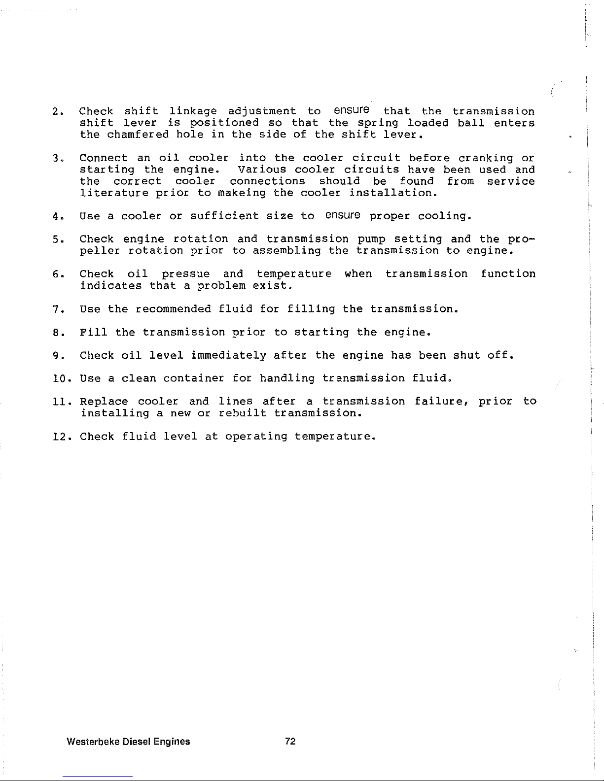
2.
Check
shift
linkage
adjustment
to
ensure
that
the
transmission
shift
lever
is
positioned
so
that
the
spring
loaded
ball
enters
the
chamfered
hole
in
the
side
of
the
shift
lever.
3.
Connect
an
oil
cooler
into
the
cooler
circuit
before
cranking
or
starting
the
engine.
various
cooler
circuits
have
been
used
and
the
correct
cooler
connections
should
be
found
from
service
literature
prior
to
makeing
the
cooler
installation.
4.
Use a cooler
or
sufficient
size
to
ensure
proper
cooling.
5.
Check
engine
rotation
and
transmission
pump
setting
and
the
pro-
peller
rotation
prior
to
assembling
the
transmission
to
engine.
6.
Check
oil
pressue
and
temperature
when
transmission
function
indicates
that
a
problem
exist.
7.
Use
the
recommended
fluid
for
filling
the
transmission.
8.
Fill
the
transmission
prior
to
starting
the
engine.
9.
Check
oil
level
immediately
after
the
engine
has
been
shut
off.
10.
Use a clean
container
for
handling
transmission
fluid.
11.
Replace
cooler
and
lines
after
a
transmission
failure,
prior
to
installing
a new
or
rebuilt
transmission.
12.
Check
fluid
level
at
operating
temperature.
Westerbeke Diesel Engines
72
Page 75

Walter V-Drives
Flange Alignment - Direct Coupled Models
Install
the
propeller
shaft
flange
on
to
the
propeller
shaft
and
tighten
the
two
clamping
bolts
on
the
spli
t
hub
(none
on
RV-lOD).
A
self-locking
set
screw
is
pro-
GEAR
SHAFT
vided
for
the
propeller
shaft
flange.
FLANGE
Spot
dr
ill
the
propeller
shaft
and
then
securely
tighten
the
set
screw.
Many
good
installations
are
ruined
by
improper
shaft
flange
alignment.
Accurate
alignment
will
ensure
a
smooth
operating
drive
train
and
eliminate
many
problems
that
arise
due
to
misalignment.
Final
alignment
should
not
be
attempted
until
the
boat
has
been
allowed
to
"settle"
in
the
water.
After
the
engine
has
been
installed,
adjust
the
mounts
per
manufacturer's
instructions
until
the
pilot
diameters
of
the
gear
shaft
flange
and
the
propeller
shaft
flange
engage
freely.
Butt
the
flange
FEELER
GAGE
CLAMPING
BOLTS
FLANGE
ALIGNMENT
SET
SCREW
faces
together.
Without
rotating
either
flange,
check
with
a
feeler
gauge
in
at
least
four
places
as
shown
in
the
illustration.
If
the
maximum
feeler
gauge
that
can
slip
between
the
flange
faces
at
any
point
is
.003",
the
unit
is
properly
aligned.
If
a
thicker
gauge
can
be
inserted
at
any
point,
the
engine
must
be
readjusted
until
proper
alignment
is
obtained.
Turn
the
propeller
shaft
flange
1/4
of
a
turn
without
moving
the
gear
shaft
change.
Try
inserting
the
.003"
feeler
gauge
as
descr
ibed
above.
The
gap
will
not
change
if
the
propeller
shaft
is
straight.
If
it
increases,
the
shaft
or
flange
is
bent
and
must
be
removed
and
straightened.
Rotate
the
propeller
shaft
flange
in
two
more
1/4
turn
increments
and
repeat
the
procedure.
The
pilot
diameters
must
be
rechecked
to
ensure
that
they
still
engage
freely.
Secure
the
two
flanges
together
with
the
heat
treated
bolts
and
spe-
cial
high
collared
lockwashers
supplied.
Engine Alignment - Independent Models
The
engine
must
be
adjusted
so
that
the
alignment
of
the
flexible
joint
is
within
3'.
An
accurate
steel
rule
should
be
used
for
this
purpose
as
shown
in
the
illustration.
On
short
installations
using
a
flexible
joint
assembly,
the
faces
of
the
flexible
joint
must
be
parallel
within
1/8".
Measure
this
in
at
least
four
places
around
the
diameter
without
rotating
the
assembly.
With
long
installations
using
the
#36
tubular
drive
shaft
(also
on
all
RV-lOD'S)
the
distance
from
the
#33A
spool
adapter
to
the
bores
in
the
universal
joint
which
is
welded
to
the
tubular
shaft
must
be
measured
on
both
sides
of
the
joint.
Rotate
the
shaft
exactly
1/4
of
a
turn
and
measure
to
the
same
joint.
The
four
distances
must
be
equal
within
1/8".
(DO
not
measure
73
Westerbeke Diesel Engines
Page 76

to
the
joint
end
that
is
on
the
spool
adapter.
This
distance
will
not
"~H',,,,,",,,,,,,
vary
wi
th
misalignment
.-
?'!
~ RI":,~
Z'
Y.'NCO
-lJ'ft[ClIN('
"'''''.
Slnce
the
joint
is
bolted
and
cannot
move.)
Put
the
#31A
alignment
gauge
on
the
machined
diameter
of
the
#24
cover
and
slide
it
com-
pletely
around.
It
will
indicate
how
the
engine
must
be
moved
to
center
the
spline
shaft
in
the
oil
seal.
Re-measure
the
joints
to
see
if
they
are
still
parallel
within
1/8".
It
is
important
that
both
alignments
be
checked
thoroughly.
It
is
possible
for
the
spline
shaft
to
be
perfectly
centered
and
the
flexible
joint
to
be
out
more
than
3'.
Premature
failure
of
the
#26
self-aligning
bearing
and
seals
may
occur
due
to
misalignment.
The
zerk
fitting
(located
on
the
cross
of
the
universal
joint)
should
be
greased
with
a
light
alemite
lubricant.
The
above
procedure
should
be
repeated
after
the
boat
has
been
placed
in
operation.
It
is
possible
for
the
engine
to
slightly
shift
and
settle,
espe-
cially
if
it
has
rubber
mounts.
Flange Alignmenl - Independenl Models
Install
the
propeller
shaft
flange
on
to
the
propeller
shaft
and
tighten
the
two
clamping
bolts
on
the
split
hub
(none
on
RV-IO).
A
self-locking
set
screw
is
provided
for
the
propeller
shaft
flange.
spot
drill
the
propeller
shaft
and
secure-
ly
tighten
the
set
screws.
All
V-drives
are
supplied
with
3-way
adjustable
mounting
brackets
(2-way
on
the
RV-IO
and
RV-20)
as
standard
equipment.
The
brackets
must
face
down-
ward
as
shown
in
the
illustration
to
properly
absorb
propeller
thrust.
The
mounting
plates
can
be
removed
and
rever:
sed
to
fi
t
wider:
eng
ine
bed
centers.
Before
installing
the
V-drive,
loosen
all
the
nuts
on
the
mounting
brackets
and
check
to
see
that
the
studs
are
in
the
center
of
the
slots.
Re-
ADJUST
I!\,(,
SChEW
/"
LOCKING
NUT
LOOSEN
~
TO
AOJUS T BRACK.[
T5
RV'IO
&.
RV-20
,
MOlJ>jTING
\
HOLE
\
tighten
the
nuts.
place
the
V-drive
on
the
engine
bed,
lining
it
up
Wby
eye"
to
the
propeller
shaft
flange
as
closely
as
possible.
Firmly
bolt
it
down
through
the
holes
provided
in
the
mounting
plates.
Loosen
the
locking
nuts
on
the
adjusting
screws.
Slightly
loosen
the
nuts
on
the
mounting
brackets
just
enough
to
be
able
to
move
the
v-
drive.
Many
good
installations
are
ruined
by
improper
propeller
shaft
flange
alignment.
Accurate
alignment
will
ensure
a
smooth
operating
drive
train
and
eliminate
many
problems
that
arise
due
to
misalign-
Weslerbeke Diesel Engines
74
Page 77
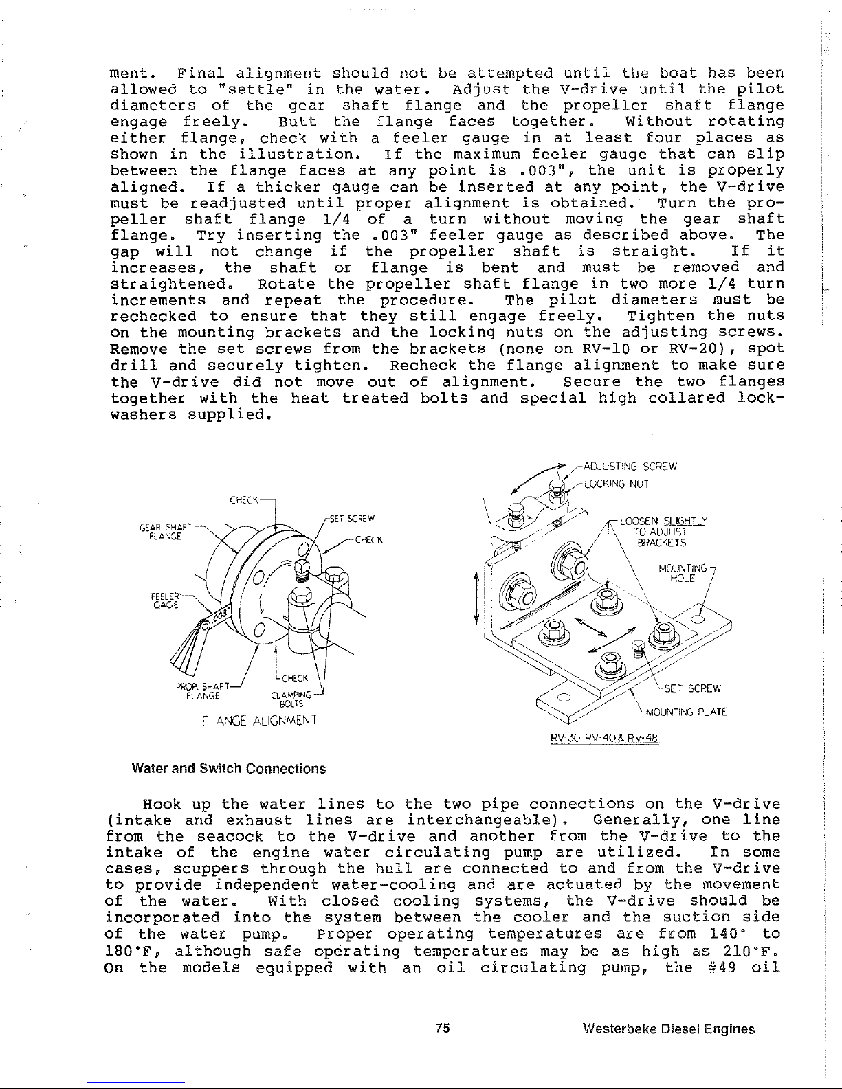
ment.
Final
alignment
should
not
be
attempted
until
the
boat
has
been
allowed
to
"settle"
in
the
water.
Adj
ust
the
V-dr i ve
until
the
pilot
diameters
of
the
gear
shaft
flange
and
the
propeller
shaft
flange
engage
freely.
Butt
the
flange
faces
together.
Without
rotating
either
flange,
check
with
a
feeler
gauge
in
at
least
four
places
as
shown
in
the
illustration.
If
the
maximum
feeler
gauge
that
can
slip
between
the
flange
faces
at
any
point
is
.003",
the
unit
is
properly
aligned.
If
a
thicker
gauge
can
be
inserted
at
any
point,
the
V-drive
must
be
readjusted
until
proper
alignment
is
obtained.
Turn
the
pro-
peller
shaft
flange
1/4
of
a
turn
without
moving
the
gear
shaft
flange.
Try
inserting
the
.003"
feeler
gauge
as
described
above.
The
gap
will
not
change
if
the
propeller
shaft
is
straight.
If
it
increases,
the
shaft
or
flange
is
bent
and
must
be
removed
and
straightened.
Rotate
the
propeller
shaft
flange
in
two
more
1/4
turn
increments
and
repeat
the
procedure.
The
pilot
diameters
must
be
rechecked
to
ensure
that
they
still
engage
freely.
Tighten
the
nuts
on
the
mounting
brackets
and
the
locking
nuts
on
the
adjusting
screws.
Remove
the
set
screws
from
the
brackets
(none
on
RV-IO
or
RV-20),
spot
drill
and
securely
tighten.
Recheck
the
flange
alignment
to
make
sure
the
V-drive
did
not
move
out
of
alignment.
Secure
the
two
flanges
together
with
the
heat
treated
bolts
and
special
high
collared
lock-
washers
supplied.
GEAR
SHAFT
FLANGE
FEELER'
GAGE
FLANGE
ALIGNMENT
Water
and Switch Connections
SET
SCREw
~
.-ADJUSTING
SCREW
/
~/LOCKING
NUT
\
~.
~:;.?
.
"".\.L.OOSEN
SLIGHTLY
/7
,;
TO
ADJUST
~
i
BRACKETS
(.(
a i
MOUNTING
ll~'
.4'"
HOLE
a " 0
.....
p
dP
~7@~
o
\MOUNTING
PLATE
Hook
up
the
water
lines
to
the
two
pipe
connections
on
the
V-drive
(intake
and
exhaust
lines
are
interchangeable).
Generally,
one
line
from
the
seacock
to
the
V-dr i ve
and
another
from
the
V-dr i ve
to
the
intake
of
the
engine
water
circulating
pump
are
utilized.
In
some
cases,
scuppers
through
the
hull
are
connected
to
and
from
the
V-drive
to
provide
independent
water-cooling
and
are
actuated
by
the
movement
of
the
water.
With
closed
cooling
systems,
the
V-drive
should
be
incorporated
into
the
system
between
the
cooler
and
the
suction
side
of
the
water
pump.
Proper
operating
temperatures
are
from
140·
to
ISO'F,
although
safe
operating
temperatures
may
be
as
high
as
210"F.
On
the
models
equipped
with
an
oil
circulating
pump,
the
#49
oil
75
Westerbeke Diesel Engines
Page 78

pressure
drop
switch
and
the
12
volt
H9A
warning
light
should
be
hooked
up
per
the
wiring
diagram.
The
switch
may
be
grounded
to
any
part
of
the
V-drive
or
engine
(either
terminal
may
be
used
for
the
ground).
Oil Fill
Pullout
the
#21
oil
level
gauge.
Unscrew
the
#12
breather
cap
and
fill
the
V-drive
with
SAE
i30
motor
oil
through
the
#12A
breather
elbow.
On
the
RV-IO
only,
the
oil
may
be
added
by
removing
the
plug
in
the
#60
top
cover.
See
table
below
for
approximate
oil
capaci
ties.
The
amount
varies
with
the
angle
of
installation.
The
oil
level
should
be
checked
wi
th
the
oil
level
gauge
fully
inserted
in
the
unit.
The
proper
level
is
between
the
"H"
and
"L"
marks
on
the
gauge.
Add a 2
ounce
tube
of
Molykote
(molybdenum
disulfide),
which
is
supplied
with
each
V-drive
for
extra
lubrication
and
break-in.
It
provi-
des
protection
against
scoring
or
galling
of
gears,
bearings
and
other
moving
parts.
"12
BREATHER
CAP
(UNSCREW
FOR
Oil
Filll
WATER
LINE
#12A
BREATHER
ELBOW
,\ATER
mAIN
~"
()L
LEVEL
c
GA(£
I
(PULL
UP
TO
J
REM:lVE)
Additional
Molykote
after
break-in
is
not
required.
Reinstall
the
breather
cap.
The
oil
level
should
be
rechecked
after
the
unit
has
been
run
and
allowed
to
sit
for
about
a
minute.
Add
oil
if
necessary.
RV-IO RV-20
RV-30 RV-40
RV-48
Oil
capaci
ty
1
pint
2
pints
3
pints
4
pints
4
pints
(Approx.
)
Dealer Preparation
The
propeller
shaft
and
engine
alignment
must
be
checked
and
corrected,
if
necessary,
before
the
boat
is
delivered.
Final
align-
ment
should
not
be
attempted
until
the
boat
is
allowed
to
"settle"
in
the
water.
The
oil
level
must
be
checked
and
oil
added
if
required.
While
the
boat
is
being
run,
the
water
connections
should
be
checked
for
leaks.
The
oil
pressure
drop
switch
and
warning
light
(if
the
V
dd
ve
is
equipped
wi
th
an
oil
circulating
pump)
should
be
checked
for
proper
operation.
Do
not
transport
the
boat
with
the
propeller
shaft
coupling
connected.
Damage
to
the
shaft,
shaft
log
and
V-drive
can
result.
Weslerbeke Diesel Engines
76
Page 79
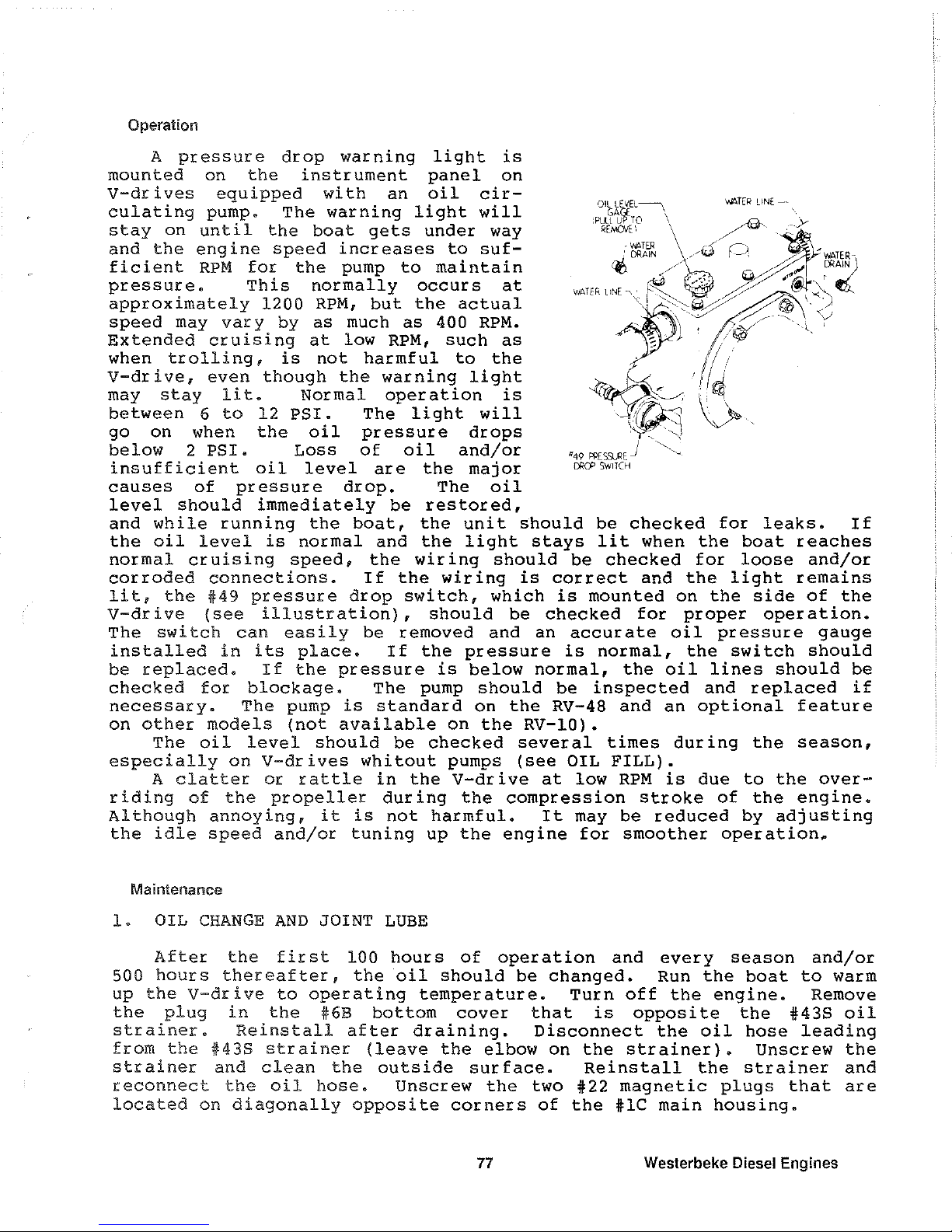
Operation
A
pressure
drop
warning
light
is
mounted
on
the
instrument
panel
on
V-drives
equipped
with
an
oil
cir-
culating
pump.
The
warning
light
will
stay
on
until
the
boat
gets
under
way
and
the
engine
speed
increases
to
suf-
ficient
RPM
for
the
pump
to
maintain
pressure.
This
normally
occurs
at
approximately
1200
RPM,
but
the
actual
speed
may
vary
by
as
much
as
400
RPM.
Extended
cruising
at
low
RPM,
such
as
when
trolling,
is
not
harmful
to
the
V-drive,
even
though
the
warning
light
may
stay
lit.
Normal
operation
is
between
6
to
12
PSI.
The
light
will
go
on
when
the
oil
pressure
drops
below
2
PSI.
Loss
of
oil
and/or
insufficient
oil
level
are
the
major
causes
of
pressure
drop.
The
oil
level
should
immediately
be
restored,
and
while
running
the
boat,
the
unit
should
be
checked
for
leaks.
If
the
oil
level
is
normal
and
the
light
stays
lit
when
the
boat
reaches
normal
cruising
speed,
the
wir
ing
should
be
checked
for
loose
and/or
corroded
connections.
If
the
wiring
is
correct
and
the
light
remains
lit,
the
#49
pressure
drop
switch,
which
is
mounted
on
the
side
of
the
V-dr i ve
(see
illustration),
should
be
checked
for
proper
oper
ation.
The
switch
can
easily
be
removed
and
an
accurate
oil
pressure
gauge
installed
in
its
place.
If
the
pressure
is
normal,
the
switch
should
be
replaced.
If
the
pressure
is
below
normal,
the
oil
lines
should
be
checked
for
blockage.
The
pump
should
be
inspected
and
replaced
if
necessary.
The
pump
is
standard
on
the
RV-48
and
an
optional
feature
on
other
models
(not
available
on
the
RV-IO).
The
oil
level
should
be
checked
several
times
during
the
season,
especially
on
V-drives
whitout
pumps
(see
OIL
FILL).
A
clatter
or
rattle
in
the
V-drive
at
low
RPM
is
due
to
the
over-
riding
of
the
propeller
during
the
compression
stroke
of
the
engine.
Although
annoying,
it
is
not
harmful.
It
may
be
reduced
by
adjusting
the
idle
speed
and/or
tuning
up
the
engine
for
smoother
operation.
Maintenance
1.
OIL
CHANGE
AND
JOINT
LUBE
After
the
first
100
hours
of
operation
and
every
season
and/or
500
hours
thereafter,
the
oil
should
be
changed.
Run
the
boat
to
warm
up
the
V-drive
to
operating
temperature.
Turn
off
the
engine.
Remove
the
plug
in
the
#6B
bottom
cover
that
is
opposite
the
#438
oil
strainer.
Reinstall
after
draining.
Disconnect
the
oil
hose
leading
from
the
#438
strainer
(leave
the
elbow
on
the
strainer).
Unscrew
the
strainer
and
clean
the
outside
surface.
Reinstall
the
strainer
and
reconnect
the
oil
hose.
Unscrew
the
two
#22
magnetic
plugs
that
are
located
on
diagonally
opposite
corners
of
the
#lC
main
housing.
77
Westerbeke Diesel Engines
Page 80

The
plugs
can
be
checked
to
see
if
they
are
magnetic
only
after
removal.
Touch
the
inside
face
with
a
metallic
object,
such
as
a
screwdriver.
Clean
them
and
reinstall.
Usually,
there
are
four
plugs
in
the
bottom
part
of
the
main
housing.
Only
two
of
these
are
magnetic.
The
other
two
need
not
be
removed
(see
illustration).
Refill
wi
th
SAE
30
motor
oil
to
the
proper
level
(see
INSTALLATION - OIL
FILL).
The
Zerk
fitting
on
the
external
uni-
versal
joint
should
be
greased
with
a
light
alemite
lubricant
(see
ENGINE
AL I GNMENT)
•
2.
WATER
DRAIN
For
protection
from
freezing
during
winter
lay-up,
remove
the
small
pipe
plugs
(located
diagonally
opposite)
on
the
front
and
back
of
the
housing
marked
"Water
Drain"
(see
illutration).
On
the
RV-IO
only,
one
of
the
water
lines
going
into
the
#6
water-cooled
bottom
cover
must
be
disconnected
to
drain
the
water.
3.
FLANGE
AND
ENGINE
REALIGNMENT
When
the
boat
is
launched
after
being
in
drydock,
the
line-up
of
the
v-drive
to
the
propeller
shaft
flange
and
the
engine
to
the
V-
drive
should
be
rechecked
and
corrected
if
necessary.
Some
engines
with
rubber
mounts
may
sag
and
must
be
raised
with
adjustments
or
shims
for
proper
alignment
(see
"Flange
Alignment"
and
"Engine
Alignment
n)
•
Westerbeke Diesel Engines
78
Page 81

ENGINE
TROUBLESHOOTING
Introduction
The tables which follow indicate troubleshooting procedures based upon certain problem indicators, the
probable causes
of
the problems, and the recommendations to overcome these problems.
Note that the engine's control system (electrical system)
is
protected
by
a 20-Ampere manual reset circuit
breaker located on the rear lifting bracket.
Problem
Key switch
ON
but
no
panel or
test function.
PREHEAT switch is depressed: no preheat
solenoid activation:
no
electric fuel pump
or
alternator excitation.
Probable
Cause
1.
Battery OFF.
2.
20
Amp circuit
breaker is tripped.
3.
Loose battery
cable connection.
1.
Faulty solenoid,
connections
or
switch.
2.
Faulty connection
or
tripped
10
Amp breaker
on the
I terminal on the
preheat solenoid.
79
Verffication/Remedy
1.
Turn Battery ON.
2.
Reset the breaker by
pushing in the button.
3.
Check the + connection
to
the starter and the -
connection
to
the ground
stud on the bell housing.
1.
Connection for
12
volts at
S terminal of the solenoid
is.
faulty.
1.
Check the preheat switch.
2.
Check for
12
volts at the
10
Amp breaker. Check
for
12
volts at
fuellifl
pump
and at the R terminal on the
alternator when the preheat
button
is
pushed.
Westerbeke Diesel Engines
Page 82

Problem
START
switch is de-
pressed:
no
starter
engagement.
Engine cranks,
but does not start.
Failure
to
stop.
Weslerbeke
Diesel
Engines
probable Cause
1.
Connection
to
starter
solenoid faulty.
2.
F aully
START
switch.
3.
Faulty solenoid.
4.
Loose battery
connection.
5.
Low batteries.
1.
Shut-off valve at
fuel tank.
2.
Faulty fueling system.
3.
Air is in the fuel
system.
4.
Fuel pump is
not
operating.
5.
Fuellilters are clogged.
1.
Mechanical Run
linkage is
disconnected.
80
Verification/Remedy
1.
Check connection S at the
starter solenoid for 12
volts
with the
SWITch
depressed.
2.
Check switch with an
ohmmeter.
3.
Twelve volts is present
at the
S terminal
of
the
starter
solenoid.
4.
Check battery connections
at both the
+ and - ground.
5.
Check battery charge state.
Low voltage at the
solenoid's
S
terminal with
no
activation.
1. Return shut-off valve
to
ITS
ON
pOSITion.
Now
bleed
the fuel system.
2.
Check
for
fuel
to
engine.
3.
Bleed the fuel system.
Locate the
leak and correct
ff.
4.
Check
pump
operation.
Check
for
12-Volts at pump.
5.
Clean/replace fillers.
1 .
Stop engine
by
manually moving the
RUN
linkage
to
STOP.
That failing,
shut
OFF fuel and air.
Page 83

Problem
Engine Stops.
Battery
runs
down.
Probable
Cause
1.
Fuel
starvation.
Fuel
shut-off
is
turned
OFF.
2.
Fuel
pump
is
inoperative.
3.
Water
is
in
the
fuel.
4.
Exhaust
system
is
restricted.
1.
Alternator output
is
low.
2.
Faulty alternator.
the alternator
when
not
operating.
3.
Bad
battery
connections.
81
Verification/Remedy
1.
Check to
see
that the
shut-off
valve
at
the
fuel
tank
is
ON.
2.
Inspect
the
fuel
pump for
12
volt
and
to
see
if
it
is
pumping.
3.
Pump water out
of
the
bottom of
the
fuel
tank(s),
change the
fuel
filters,
and
bleed
the
fuel
system.
4.
Check exhaust
system
for
some type
of
blockage
such
as
carbon buildup
at
the exhaust
elbow.
Check
for a fault
In
the muffler.
Check for a collapsed
exhaust
hose.
1.
Check drive belt tension.
Perform
an
output check
w~h
a voltmeter at
the
B +
terminal
on
the alternator.
2.
Voltage leak through
3.
Connections
are
corroded
or loose at the battery or/and
at the
engine.
Westerbeke Diesel Engines
Page 84

MAINTENANCE AND ADJUSTMENTS
Introduction
This section contains a scheduled preventive maintenance program and several adjustment procedures the
owner/operator can perform without the benefit of sophisticated and expensive
tools and instruments.
Preventive
Maintenance
Perform the preventive maintenance in accordance with the schedules listed
in
the following paragraphs.
Adherence
to
these schedules will ensure the equipment is maintained in the best possible condition and
that it will perform
to
expectations. Those items marked
by
an
asterisk
(*)
are recommended
to
be per-
formed
by
an authorized dealer or distributor.
Daily
(before
each
use)
1.
Check the oil sump level. Maintain the oil level at or near upper level mark on dipstick.
2.
Check the coolant level
in
the plastic recovery tank. Maintain this level at
or
above the level marked
ADD.
3.
Check the transmission's lubricant level, and add additional lubricant as needed.
4.
Visually inspect the unit; check for loose belts, chafed or broken wires, loose brackets and fittings,
damaged hoses,
loose clamps, and other equipment not properly secured. This check should include
the
propeller shaft coupling
to
the transmission's output flange.
5.
Check the fuel supply. Fill tank(s) with a good grade
of
No.2
diesel fuel, if required.
6.
Check the primary filter/water separator. Drain and service as required.
(A
primary filter/Water separator
is
optional, but strongly recommended.)
7.
Check the engine's gauges
or
lights for proper oil pressure, operating temperature, and starting bat-
tery charging
voltage once the engine
is
operating.
8.
Check the alternator's output gauge (if installed) for proper DC voltage.
9.
Check to make sure the propeller shaft
is
securely connected
to
the transmission coupling.
Monthly
Check the condition
of
the zinc anode
in
the heat exchanger's
sea
water circuit. Clean or replace the anode,
as required. Keep the area inside the heat exchanger clean of zinc anode debris.
Westerbeke
Diesel
Engines
82
Page 85
Servicing
Alter
Initial
50
Hours
01
Operation
1.
Change the engine's lubrication oil and oil filter.
2. Replace the fuel filter element in the electric fuel lift
pump
and in the engine-mounted secondary fuel fil-
ter. Change the fuel filter element and clean the optional filter/water sediment or, H a separator has been
installed, and
il
the model type permits cleaning.
*3. Torque the cylinder head bolts.
*4. Adjust valve clearances.
5.
Adjust the alternator and water
pump
drive belt tension, if required.
6. Lubricate the throttle, the RUN linkage cable, and the transmission's remote control cable.
7. Change the transmission's oil.
8. Adjusts the engine's idle speed as needed.
9. Check
to
make sure the propeller shaft is securely connected
to
the transmission coupling.
Servicing
Alter
Every
100
Hours
of
Operation
1.
Change the engine's lubrication oil and oil filter.
2. Adjust the alternator and water
pump
drive belt tension, if required.
3. Check the transmission fluid
or
oil level.
Servicing
Alter
Every
250
Hours
of
Operation
1. Replace the fuel filter elements
in
the electric fuel lift
pump
and in the engine-mounted secondary fuel
filter.
2. Change the transmission's oil.
Servicing
Alter
Every
SOO
Hours
01
Operation
*1. Torque the cylinder head bolts.
*2. Adjust the valve clearances.
3. Drain,
flush, and refill the fresh water cooling system. The illustration on pages 6
to
11
show the heat
exchanger and the zinc anode location. The drain plug
for
the fresh water system is next
to
the zinc
anode.
*4. Check the condition of the starter
motor
drive pinion; lubricate the pinion.
83
Westerbeke
Diesel
Engines
Page 86

5.
Check the resistance
of
the glow plugs.
(.4
to .6 ohms)
6.
Check the sea water pump for internal wear. Examine the pump's cover, cam, and internal housing.
Replace worn parts as needed. Check for leaks and repair as needed.
NOTE: Items highlighted by
an
asterisk
(*)
should be performed
by
a competent mechanic.
Servicing
Aller
Every 800 Hours
01
Operation
*1. Remove and check fuel injectors.
Injector spray pressure:
1991
psi + 140 psi
(140
kg/cm
2
+
10
kglcm
2
)
Eliminate undesirable injection conditions including
aller dripping.
*2. Check the engine's compression pressure.
Remove each
glow
plug
and
check
each
cylinder's compression pressure. The engine's
cranking speed is at 280 rpm.
Standard Minimum
POOR
(i~~.
f~~~:
i'r. , ...
4
10104i
....... '
--~dI\
GOOD
455 psi
(32
kg/cm
2
)
369.7 psi
(26 kglcm
2
)
(Maximum difference between cyfinders: 35.5 psi (2.5 kg/cm
2
)
*3. Check the battery-charging alternator for proper operation.
*4. Check the tightness of
bolts, nuts, and clamps.
Servicing
Aller
Every 1000 Hours
of
Operation
1.
Remove, clean, and pressure test the primary heat exchanger.
(A
local automotive radiator shop should
be able to clean and test the heat exchanger.)
NOTE: Operating
in
silty and/or tropical waters may require that a heat exchanger cleaning
be performed more often than every
1000
hours.
*2. Check the injection pump's timing.
Westerbeke
Diesel
Engines
84
Page 87

Torquing
Cylinder
Head
Bolts
CN
35B THREE Engine)
Tighten the cylinder head
bolts according to the
sequence shown in the illustration shown
to
the
right. Make sure the engine is cold when this is
done. Before applying the specHied torque
to
the bolt, loosen it 1/4
to
1/2
of
a turn and then
apply the torque. Follow this procedure according
to
the numbered sequence shown in
the illustration
to
the right.
Bolts # 4,5,6,7,8,9,10 and
11
are tightened be-
1ween 79.5
to
86.8Ib-ft
(11
to
12
kg-m).
Bolts # 1,2 and 3 are tightened
be1ween
50.6
to
57.8 Ib-ft
(7
to
8 kg-m).
FRONT
~
OF
ENGINE
0
7
4
0
02
Torquing
Cylinder
Head
Bolts
(W
38B FOUR and W 42B FOUR Engine)
Tighten the cylinder head
bolts according
to
the sequence shown in the illustration shown
to
the right. Make sure the engine
is
cold when
this is done. Before applying the spec
Hied
torque
to
the bolt, loosen
IT
1/4
to
1/2 of a turn
and then
apply the torque. Follow this proce-
dure according
to
the numbered sequence
shown in the illustration
to
the right.
Bolts # 4,5,6,7,8,9,10 and
11
are tightened be-
1ween
79.5
to
86.8Ib-ft (1110
12
kg-m).
Bolts # 1,2 and 3 are tightened
be1ween
50.6
to
57.8 Ib-ft (7
to
8 kg-m).
FRONT
OF
ENGINE
~
0
6
14
8
0
10
0
4
0
0
85
0
0
5
11
6 8
0
0
01
03
0
0
0
1 5
11
2
1
13
0
3
0
9
0
0
0
Westerbeke Diesel Engines
Page 88

Valve Clearance
Adjustment
rN
35B THREE Engine)
CAUTION
Adjust the valve clearance when the
engine is cold.
Valves are adjusted
by
cylinder in the firing order
of
the en-
gine.
Tighten the cylinder head bolts to the
specified torque before adjusting the
valves.
(See page 85.)
1.
Pull off the air breather pipe from the rock-
TO C MA
R K
er cover, and take off the rocker cover
(C
y
li
n d e r
bolts and the rocker cover.
No.3
1
2.
Adjust the valve clearances at TDC (Top
Dead Center) for each cylinder when they
are on
their
compression stroke (see
below). Remember the engine's firing
\
TOC
MRRK ( Cylinder
Ko.ll
TOC
MARK
(Cylinder
No.2l
order is 1-3·2. You may find that turning the engine's crankshaft
is
more easily accomplished when the
engine's glow plugs are removed before the crankshaft
is
rotated.
A.
Align the timing mark on the gear case with the timing mark on the crankshaft pulley indicated for
cylinder
NO.1 (the one next
to
the three injection timing marks). In this position, the NO.1 cylinder
is
at ks
top
Timing Mark while dead center on ks compression stroke. Check both intake and exhaust
valve clearances for this cylinder.
If the valves have no specified clearance, adjust by means of the ad-
justing screws. Remember
to
align the timing marks properly; if not, the valve may be pushed up
by
the piston, depending on the position of the cam lobe.
Be
sure
to
check the valves for this cylinder -
they both should be closed.
B.
Next the
No.3
cylinder: Turn the crankshaft clockwise
240°
so the TDC mark for the NO.3 cylinder, on
the front crankshaft
pulley, is approximately
at
the position shown in the illustration above.
Now
adjust the intake and exhaust valves for
cylinder
No.3.
Be sure
to
check the valves
for
this
cylinder-they
both should be closed. ADJUST VALVES
TO
0.010
INCHES
(0.25
MMJ
C.
Last
is
the
No.2
cylinder: Turn the crankshaft
clockwise another
240°
to
position the TDC
mark on the crankshaft
pulley approximately
at the position shown in the illustration shown
above.
Now
adjust the intake and exhaust
valves for cylinder
NO.2.
Be
sure to check
the valves for this cylinder -they both should
be closed.
Adjust each valve's clearance by inserting a
0.010
inch (0.25 mm) feeler gauge between the rocker
arm and the valve stem.
Westerbeke Diesel Engines
86
Page 89

Valve Clearance
Adjustment
(W
38B FOUR and W 42B FOUR Engines)
CAUTION
Adjust the valve clearance when the
engine is cold.
Tighten the cylinder head bolts
to
the
specHied torque before adjusting the
valves. (See page 85.)
\.
TDC
MARK
Position
for
Cylinder.
No.1
and
4
1.
Pull off the air breather pipe from the rock-
er cover, and take off the rocker cover
bolts and the rocker cover.
\
~'"''
'
2.
Adjust the valve clearances
atTDC
(fop
TOC
MARK
~
~
Dead Center) for each cylinder when they
Po.
i t
ion
for
are on their compression stroke. Remem- C y 1 i n
d.
r s
berthe engine's firing order
is
1-3-4-2. The
No.2
and
3
engine's valves must be adjusted in this
order while the
valves are closed. You
may
find
that
turning
the
engine's
crankshaft
is
more easily accomplished
when
the
engine's
glow
plugs
are
removed before the crankshaft
is
rotated.
CRANKSHAFT
PULLEY
A.
Rotate the engine in the normal direction
of
rotation placing the
NO.1
cylinder at the
top
of
its compres-
sion stroke. The TDC mark on the crankshaft
pulley should be in line with the pointer on the front of the
gear case cover, and the
valves for the No.1 cylinder should be closed.
Now
adjust the intake and ex-
haust
valves for cylinder NO.1.
B.
After adjusting the valves for cylinder No.1, rotate the front crankshaft pulley clockwise 180" so the TDC
mark on the
pulley is positioned approximately in the position shown in the illustration shown above for
cylinder
No.3.
Now
adjust the intake and
exhaust
valves for cylinder NO.3.
C.
Rotate the crankshaft pulley clockwise
another
180" and adjust the valve clearances
for
the Intake and exhaust valves for cylinder
No.4.
D.
Rotate the crankshaft pulley clockwise
another 180" and adjust the valve clearances
for the intake and exhaust valves for cylinder
NO.2.
Adjust each valve's clearance
by
inserting a 0.010
inch (0.25 mm) feeler gauge between the rocker
arm and the
valve stem.
87
ADJUST
VALVES
TO
0.010
INCHES
(0.25
MMJ
Westerbeke Diesel Engines
Page 90

Injection
Pump
Timing
Adjustment
(Spill
Timing)
If your engine's fuel injection timing is not property adjusted, the engine will not operate property and will be
difficult
to
start. Have the injection pump delivery rate checked by a well-established fuel Injection shop. Ad-
just the injection timing as follows:
NOTE: The fuel shut-off lever must be
In
the RUN posHion while making the adjustment or
no
fuel will flow from the fuel injection pump.
Refer
to
the illustration below when servicing the fuel injection pump. First remove the high-pressure fuel
line from between the No.1 injector and the
No.1
fuel delivery valve holder. Remove the NO.1 fuel delivery
valve holder and remove the delivery valve spring beneath the holder. Reinstall only the delivery valve holder
and re-attach the high pressure fuel
line
to
the delivery holder. Attach H so that the end that would connect
to
the fuel injector
is
pointing away from the engine. Fuel will flow from this line during the timing check.
Rotate the engine's crankshaft in
Hs
normal direction
of
rotation
to
posi-
tion piston No.1 at the beginning
of
its compression stroke
Move the throttle lever
to
Hs
full open
position and operate the electric lift
pump.
Slowly rotate the crankshaft
clockwise
(as
viewed
from
the
front), catching the fuel from the No.
1 fuel
line, until the Instant the fuel
completely stops flowing (no drips).
At this instant, the
230 BTDC timing
mark
on
the
crankshaft
pulley
should be directly aligned
wHh
the
timing indicator on the front of the
gear case (refer
to
the illustrations
on pages 86 and 87).
DELIVERY
VALVE
HOLDER
DELIVERY
VALVE
SPRING
DELIV
VALVE
BAR
R E L
'-::::"':17'TtJt;1
PLUNGER
CONTROL
PINION
PLUNGER
SPRING
7';I"'-::'-~-CONTROL
RACK
TAPPET
If the specified injection timing
(230 BTDC) cannot
be
attained, adjust the timing
by
increasing or decreas-
ing the thickness
of
shim material under the injection pump's mounting flange to change the injection timing
point. Changing the shim thickness
by
0.004 inch
(0.01
mm) changes the injection timing
by
approximately
one degree. To advance the timing, decrease the shim thickness, as required. To retard the timing, increase
the shim thickness, as required. Refer
to
your engine's Parts List for shim part numbers.
Weslerbeke
Diesel
Engines
88
Page 91

LAY-UP
AND
RECOMMISSIONING
General
Many
owners rely on their boatyards
to
prepare their cralt, including engines and generators, for lay-up
during
the off-season
or
lor
long periods
of
inactivity. Others prefer
to
accomplish lay-up preparation them-
selves.
The
procedures
which
follow will allow you
to
perform
your
own
lay-up and recommissioning,
or
to
use as
a
check
list
il
others
do
the
procedures.
These procedures should afford
your
engine protection during a lay-up and also help familiarize you with
the maintenance needs
of
your
engine.
If
you
have
any
questions regarding lay-up procedures, call
your
local servicing dealer; he will
be
more than
willing
to
provide assistance.
Propeller
Shall
Coupling
The transmission and propeller half couplings should always
be
opened
up
and
the
bolts removed when-
ever
the
boat
is hauled out of
the
water
or
moved
Irom
land
to
water, and
during
storage in a cradle. The
flexibility
01
the
boat
often
puis
a severe strain on the propeller shalt
or
coupling,
or
both, while
the
boat
is
taken
out
or
put
in the water. In some cases,
the
shalt has actually been bent
by
these strains. This
does
not
apply
to
small boats that are hauled
out
01
the
water when not in use, unless
they
have been
dry
for
a
considerable period of time.
Fresh
Water
Cooling
System
A 50-50 solution
01
antifreeze and fresh water is recommended
for
use in
the
fresh water cooling system
at
all times. This solution
may
require a higher concentration
of
antifreeze, depending
on
the
area's winter
climate.
Check
the solution
to
make sure the antifreeze protection is adequate.
Should more antifreeze
be
needed, drain an appropriate
amountfrom
the engine
block
and
add a more con-
centrated mixture. Operate the engine
to
ensure a complete circulation and mixture of
the
antifreeze con-
centration
throughout
the cooling system.
Now
recheck the antifreeze solution's strength.
Engine
lubrication
System
With rhe engine warm, drain all the lubricating oil from
the
oil sump. Remove and replace
the
oil filter. (Place
some
paper towels and a plastic bag around
the
filter
to
catch
the
oil
during
its removal.)
When
installing
the
new
oil filter, be sure
to
apply
a small
amount
of
oil on
the
rubber
sealing gasket
at
the
base of
the
filter. Fill the
sump
with the correct
amount
of
oil
for
your
engine. (Refer
to
the"SYSTEM
SPECIFICATIONS"
section of this manual, page
13
forthe
W 358,
page
16
for
the
W 38B, and page 19 for
the
W 42B.) Use an oii with an
API
specification
01
CC
or
CD. Run
the
engine and
check
for
proper
oil pres-
sure and make sure there are no leaks.
89
Weslerbeke
Diesel
Engines
Page 92

CAUTION
Do
not
leave
the engine's old lubricating
oil
in
the
sump
over the lay-up period. Lubricating
oil
and
combustion deposits combine to produce harmful chemicals which can reduce the
life of your engine's internal
parts.
Transmission
lubrication
System
Fill
the transmission completely
full
of the
same
oil
that
was
use
during its operating
season.
DO
NOT
mix
grades of
oil.
Filling the transmission immerses the transmission's internal components
in
oil
which protects
them against corrosion during the lay-up period.
Fuel System
Top off your
fuel
tanks with NO.2 diesel
fuel.
Fuel
additives should
be
added at this time to control algae
and
condition the
fuel.
Care
should
be
taken that the additives
used
are
compatible with the primary fil-
ter/water separator used
in
the
system.
Change
the element
in
your primary
fuel
filter/water separator, if the
fuel
system contains
one,
and
clean the separator sediment bowl.
Change
the
fuel
filter elements
on
the engine
and
bleed the
fuel
system,
as
needed.
Start the engine
and
allow it to
run
for 5 -
10
minutes to
make
sure
no
air
is
left
in
the
fuel
system.
Check for any leaks that may
have
been
created
in
the
fuel
system during this servicing, correcting them
as
needed.
Sea
Water Circuit
Close
the through-hull
sea
cock.
Remove
the
sea
water intake hose from the
sea
cock.
Place
the
end
of
this hose into a
5-gallon bucket of clean fresh water. Before starting the
engine,
check the zinc anode found
in
the primary heat exchanger
on
the engine
and
clean or replace it
as
required,
and
also clean any zinc
debris from inside the heat exchanger where the zinc anode
is
located.
Clean
the
sea
strainer, if
one
is
in-
stalled
in
the inside of the hull.
Start
the engine and allow the
sea
water pump to draw fresh water through the system.
When
the bucket
is
empty, stop the engine
and
refill
the bucket
wah
an
antifreeze solution slightly stronger than needed for
winter freeze protection
in
your
area.
Start the engine and allow
all
of this mixture to
be
drawn through the
sea
water
system.
Once the bucket
is
empty, stop the engine. This antifreeze mixture should protect the
sea
water circuit from freezing during
the winter lay-up,
as
well
as
providing corrosion protection.
Remove
the impeller from your
sea
water pump
(some
antifreeze mixture will accompany
it,
so
catch it
in
a
bucket). Examine the
impeller. Acquire a replacement, if
needed,
and
a cover gasket.
Do
not replace the
impeller (into the pump) until recommissioning,
but
replace the cover
and
gasket.
Weslerbeke
Diesel Engines
90
Page 93

Intllke
Manifold and Through-Hull Exhaust
Place a clean clolh, lightly soaked in lubricating oil, in the opening of the intake manifold
to
block the open-
ing. Do
not
shove the cloth out
of
sight. (If it is not visible at recommissioning, and an attempt is made
to
start the engine, you may need the assistance of a servicing dealer.) Make a note
to
remove the cloth prior
10 start-up. The through-hull exhaust part can be blocked
in
the same manner.
Starter
Molor
Lubrication and cleaning of the starter drive pinion is advisable,
if
access
to
the starter permits its easy
removal. Make sure the battery connections are shut off before attempting
to
remove the starter. Take care
in properly replacing any electrical connections removed from the starter.
Cylinder
Lubrication
It is not necessary
to
remove the fuel injectors from the cylinder head
to
squirt light lubricating oil into the
cylinders for
the few months
of
normal lay-up. However,
if
you anticipate a longer lay-up period (12 months
or
more),
we
recommended that this procedure be performed. The light oil in the cylinders will prevent the
pistons rings from sticking
to
the cylinder walls. Make sure you have replacements for the injector and return
line sealing washers.
Spares
Lay-up time provides a good opportunity
to
inspect
your
Westerbeke engine
to
see
ff
external items such
as drive belts
or
coolant hoses need replacement. Check
your
basic spares kit and order items
not
on hand,
or
replace those items used during the lay-up, such as filters and zinc anodes.
Batleries
If batteries are
to
be left on board during the lay-up period, make sure they are fully charged, and will remain
thaI way,
to
prevent them from freezing. If there exists any doubt that the batteries will not remain fully
charged,
or
that they will be subjected
to
severe environmental conditions, remove the batteries and store
them
in a warmer, more compatible environment.
Recommissioning
The recommissioning
01
your Westerbeke engine after a seasonal lay-up generally follows the same proce-
dures
as
lhose
presented in the "PREPARATIONS
FOR
STARTING" seclion, page 33, regarding preparation
for starting
and normal starts. However, some
of
the lay-up procedures will need
to
be counteracted before
slarting the engine.
1.
Remove the oil-soaked cloths from the intake manifold and from the through-hull exhaust port.
2. Remove Ihe sea water pump cover and gasket and discard the old gasket. Install the sea water pump
impeller removed during lay-up (or a replacement, if required). Install the sea water pump cover with a
new cover gasket.
91
Weslerbeke Diesel
Engines
Page 94

3. Drain the transmission of all oil. Fill the transmission
to
the proper level with the correcttype
of
oil specified
in
your
engine's "SYSTEM SPECIFICATIONS" section of this manual.
IWARNINGI
Wear rubber gloves, a rubber apron, and eye protection when servicing batteries.
Lead acid batteries emit hydrogen, a highly-explosive gas, which
can be ignited
by
electrical
arcing
or
a lighted cigarette, cigar,
or
pipe. Do not smoke
or
allow an open flame near the
battery being serviced.
Shut off all electrical equipment in the vicinity
to
prevent electrical ar-
cing during servicing.
3.
Reinstall the batteries that were removed during the lay-up, and reconnect the battery cables, making
sure the terminals are clean and that the connections are tight. Check
to
make sure that the batteries are
fully-charged.
4. Check the condition
of
the zinc anode
in
the sea water circuit and clean
or
replace the anode as needed.
Note that it is not necessary
to
flush the antifreeze/fresh water solution from the sea water coolant sys-
tem. When the engine is put into operation, the system will self-flush in
a short period
of
time with no ad-
verse affects.
5.
Start the engine in accordance with procedures
in
the "PREPARATIONS
FOR
STARTING" section
ofthis
manual, page 33.
Weslerbeke
Diesel
Engines
92
Page 95
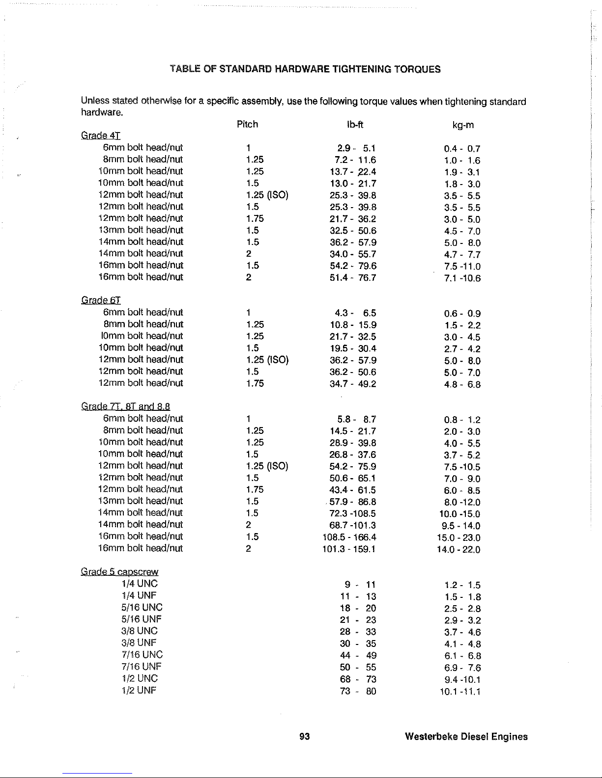
TABLE
OF
STANDARD
HARDWARE
TIGHTENING
TORQUES
Unless stated otherwise
for
a specific assembly. use
the
following
torque
values
when
tightening standard
hardware.
Pitch
Ib-ft
kg-m
Grnde
4T
6mm
bolt
head/nut
1
2.9 -
5.1
0.4-
0.7
Bmm
bolt
head/nut
1.25
7.2-
11.6
1.0 - 1.6
10mm
bolt
head/nut
1.25
13.7 - .22.4
1.9 -
3.1
10mm
bolt
head/nut
1.5
13.0 - 21.7
1.8 -
3.0
12mm
boll
head/nut
1.25 (ISO)
25.3 - 39.8
3.5 - 5.5
12mm
bolt
head/nut
1.5
25.3 - 39.8
3.5 - 5.5
12mm
bolt
head/nut
1.75
21.7 - 36.2
3.0 - 5.0
13mm
bolt
head/nut
1.5
32.5 -
50.6
4.5 - 7.0
14mm
bolt
head/nut
1.5
36.2 - 57.9
5.0 - 8.0
14mm
bolt
head/nut
2
34.0 - 55.7
4.7 - 7.7
16mm
bolt
head/nut
1.5
54.2 - 79.6
7.5-11.0
16mm
bolt
head/nut
2
51.4-76.7
7.1
-10.6
Grade6T
6mm
bolt
head/nut
1
4.3 -
6.5
0.6 - 0.9
8mm
bolt
head/nut
1.25
10.8 - 15.9
1.5 - 2.2
10mm
bolt
head/nut
1.25
21.7 - 32.5
3.0 - 4.5
10mm
bolt
head/nut
1.5
19.5 - 30.4
2.7 - 4.2
12mm
bolt
head/nut
1.25 (ISO)
36.2 - 57.9
5.0 - 8.0
12mm
bolt
head/nut
1.5
36.2 - 50.6
5.0 - 7.0
12mm
bolt
head/nut
1.75
34.7 - 49.2
4.8 - 6.8
Grade 7T aT a[]d !l.!l
Smm
bolt
head/nut
5.8 - 8.7
0.8 - 1.2
Bmm
bolt
head/nut
1.25
14.5-
21.7
2.0 - 3.0
lOmm
bolt
head/nut
1.25
28.9 - 39.8
4.0 - 5.5
1 Dmm
bolt
head/nut
1.5
26.8 -
37.S
3.7 - 5.2
12mm
bolt
head/nut
1.25 (ISO)
54.2 - 75.9
7.5-10.5
12mm
bolt
head/nut
1.5
50.6 - 65.1
7.0 - 9.0
12mm
bolt
head/nut
1.75
43.4 - 61.5
6.0 - 8.5
13mm
bolt
head/nut
1.5
.57.9
- 86.8
8.0 -12.0
14mm
bolt
head/nut
1.5
72.3 -108.5
10.0 -15.0
14mm
bolt
head/nut
2
68.7 -101.3
9.5 - 14.0
16mm
bolt
head/nut
1.5
108.5 - 166.4
15.0 - 23.0
16mm
bolt
head/nut
2
101.3 - 159.1
14.0 - 22.0
Grade
(;
QapSQ[9W
1/4
UNC
9 -
11
1.2 - 1.5
1/4
UNF
11
-
13
1.5-
1.8
5/16
UNC
18
- 20
2.5 - 2.8
5/16
UNF
21
- 23
2.9 - 3.2
3/8
UNC
28 - 33
3.7 - 4.6
3/8
UNF
30 - 35
4.1
- 4.8
7/16
UNC
44
- 49
6.1
- 6.8
7/16
UNF
50 - 55
6.9 - 7.6
1/2
UNC
68
- 73
9.4-10.1
1/2
UNF
73 -
80 10.1-11.1
93
Westerbeke
Diesel
Engines
Page 96

Cylinder head bolt
TORQUE SPECIFICATIONS
(M10)
(M12)
50.7 - 57.9
79.6 - 86.8
7.0 - 8.0
11.0-120
(See
the"
Torquing
Cylinder
Head Bolts" section of this manual on page 85.)
Crankshaft pulley nut
108.5 -180.8 20.0 - 25.0
Main bearing
cap
bolt
36.2 - 43.4 5.0 - 5.5
Connecting rod
cap
nut
23.1
- 25.3
3.2 - 3.5
Flywheel bolt -
WITh
separate washers
83.2 - 90.4 11.5 - 12.5
Flywheel bolt - washer attached
95.0 -100.0 13.0
-14.0
Oil pan drain plug
36.2 - 43.4 5.0 - 6.0
Oil filter
8.0 - 9.4
1.1
-1.3
(or tighten firmly
by
hand)
Delivery valve holder (injection pump) 28.9 - 36.2 4.0 - 5.0
Nozzle mounting bolt 10.8
-14.5
1.5 - 2.0
Nozzle holder
and retaining nut 43.4 - 57.9 6.0 - 8.0
Glow plug
10.8
-14.5
1.5 - 2.0
* NOTE: M8 indicates Metric, 8 mm thread diameter
Westerbeke
Diesel
Engines
94
Page 97

SPARE
PARTS
Since a possibility exists
in
which the engine may need to
be
serviced at
sea
or while
in
a port other than
your home port, certain spare parts should
be
kept
on
board to help minimize delays
in
your voyage.
Please
refer to your engine's Parts List for part numbers when ordering spare parts.
Listed below are those spare parts that should
be
carried
on
board at
all
times.
1.
An
Impeller Kit
2. A
Fuel
System hardware
Kit
3.
An
Electric
Fuel
Lift
Pump Filter and a Secondary
Fuel
Filter.
4.
An
Alternator/Sea Water Pump Belt
5. Hose Clamps
6. A Spare
Oil
Filter with a Spare Quart of
Diesel
Service Engine
Oil
along with a Quart of Transmission
Oil
and a Gallon of Premixed Antifreeze.
Other parts, whose
Ine
expectancy cannot
be
accurately predetermined, should
be
carried
on
board
(in
ad-
dition
to
those listed above) especially if the
vessel
is to
be
taken on long ocean voyages. These parts
are
listed below.
1.
Fuel
Injectors
2. Glow Plugs
3. Cooling System Hoses
4.
An
Alternator
5.
A Starter
6. A 20 Amp
DC
Circuit Breaker
7.
An
Electric
Fuel
Lift Pump
8.
A
Sea
Water Pump
ora
Major Overhaul
Kit
(the pump's part number
is
found
on
the cover of the pump).
9. Battery Terminal Connectors
The
spare parts listed directly above are those
we
recommend
be
carried
on
board during long ocean
voyages. You may wish to ask other boat owners who
have
similar crafts and who
have
completed long
ocean voyages
as
to what spare parts they carried
on
board and what parts were needed at specific times
of the voyage. From the list provided directly above
and
from these inquiries, you can determine what spare
parts may
be
needed.
In
addition, if you are planning a long ocean voyage, consult your local Westerbeke
dealer for a listing of the Westerbeke dealers located
on
your route.
95
Westerbeke Diesel Engines
Page 98

INDEX
A
Adjustment, Injection Pump Timing ............................................................................................................
88
ADJUSTMENTS,
MAINTENANCE
AND
......................................................................................................
82
Adjustment,
Valve
Clearance
0N
35B
THREE
Engine)
..............................................................................
86
Adjustment,
Valve
Clearance
0N
38B
FOUR
and W 42B
FOUR
Engines)
................................................
87
Admirals
Panel
.............................................................................................................................................
37
Admirals
Panel
Control Circutt
DC
Wiring
Diagram #
36844
........................ _ ..............................
50
and
51
Alignment
of
the
Engine
(Installation
Checks)
............................................................................................
24
Alternator ......................................................................................................................................................
46
Alternator
and
Water Pump
Drive
Belt
Tension
..........................................................................................
55
ANTIFREEZE
CONCENTRATION
DATA.
....................................................................................................
53
Automatic
Alarm
System .............................................................................................................................
31
B
Batteries (Lay-up
and
Recommissioning) ...................................................................................................
91
Battery Specification ...................................................................................................................................
.46
Belt Tension, Alternator
and
Water Pump
Drive
.........................................................................................
55
Bolts,
Engine (Installation
Checks)
.............................................................................................................
23
Bolts, Torquing Cylinder
Head
0N
35B
THREE
Engine)
............................................................................ 85
Bolts,
Torquing Cylinder
Head
0N
38B
FOUR
and W 42B
FOUR
Engines)
.............................................. 85
Break-in Procedures,
Engine
.....................................................................................................................
.41
C
CAUTIONS
SHIPPING ENGINE WITHOUT
ENGINE
OIL ......................................................................
'"
21
LIFTING SUNGS ...................................................................................................................
22
TIGHTENING
THE
EXHAUST ELBOW CLAMP .....................................................................
29
THROUGH-HULL FITTINGS ..................................................................................................
30
PROLONGED ENGINE CRANKING ......................................................................................
39
SHUTTING
DOWN
THE
ENGINE
..........................................................................................
41
PROLONGED ENGINE CRANKING ......................................................................................
44
BATTERY CIRCUIT ...............................................................................................................
46
QUICK-CHARGING
THE
BATTERIES ...................................................................................
46
TESTING
THE
ALTERNATOR ...............................................................................................
46
EXCESSIVE BELT
TENSION
................................................................................................
55
TRANSMISSION
GEAR
BOX
LEVER
COVER
BOLTS ...........................................................
65
ADJUSTING VALVE CLEARANCES .....................................................................................
86
ADJUSTING VALVE CLEARANCES .....................................................................................
87
LEAVING
OLD
ENGINE
OIL
IN
SUMP
OVER
LAY-UP
..........................................................
90
Captains
Panel
.............................................................................................................................................
35
Captains
Panel
Control Circuit
DC
Wiring
Diagram #
36467
.......................................................
48
and
49
Change,
Engine
Oil,
(to
include filter) .........................................................................................................
61
Charging Voltage
Test
................................................................................................................................
.47
CHECKS,
INSTALLATION
...........................................................................................................................
21
Westerbeke Diesel Engines
96
Page 99
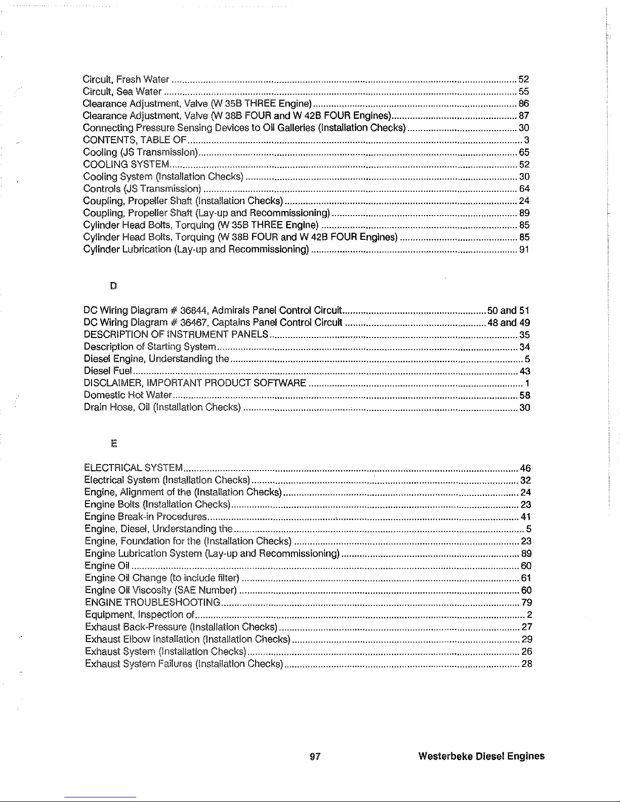
Circuit,
Fresh
Water ....................................................................................................................................
52
Circutt,
Sea
Water .......................................................................................................................................
55
Clearance Adjustment,
Valve
0N
358
THREE
Engine) ..............................................................................
86
Clearance Adjustment,
Valve
0N
388
FOUR
and
W 428
FOUR
Engines) ................................................
87
Connecting Pressure Sensing Devices to
Oil
Galleries (Installation Checks) ..........................................
30
CONTENTS,
TABLE
OF
................................................................................................................................ 3
Cooling
(JS
Transmission) ..........................................................................................................................
65
COOLING
SySTEM
.....................................................................................................................................
52
Cooling System (Installation Checks) ........................................................................................................
30
Controls
(JS
Transmission) ........................................................................................................................
64
Coupling, Propeller Shalt (Installation Checks) .........................................................................................
24
Coupling, Propeller Shalt (Lay-up
and
Recommissioning) .......................................................................
89
Cylinder
Head
Bolts, Torquing
0N
358
THREE
Engine) ...........................................................................
85
Cylinder Head Bolts, Torquing
0N
38B
FOUR
and W 42B
FOUR
Engines) .............................................
85
Cylinder Lubrication (Lay-up
and
Recommissioning) ...............................................................................
91
DC
Wiring Diagram #
36844,
Admirals
Panel
Control Circuit .......................................................
50
and
51
DC
Wiring Diagram # 38467, Captains
Panel
Control Circuit ......................................................
48
and
49
DESCRIPTION
OF
INSTRUMENT
PANELS
...............................................................................................
35
Description of Starting System ...................................................................................................................
34
Diesel
Engine,
Understanding the ................................................................................................................ 5
Diesel
Fuel
...................................................................................................................................................
43
DISCLAIMER,
IMPORTANT
PRODUCT
SOFTWARE
.................................................................................. 1
Domestic
HoI Waler ....................................................................................................................................
58
Drain
Hose,
Oil
(Installation Checks) .........................................•...............................................................
30
E
ELECTRICAL
SYSTEM
................................................................................................................................
46
Electrical System (Installation
Checks)
......................................................................................................
32
Engine, Alignment of the (Installation Checks) ..........................................................................................
24
Engine Bolts (Installation Checks) ..............................................................................................................
23
Engine Break-in Procedures .................................................•.....................................................................
41
Engine,
Diesel,
Understanding the ............................................................................................................... 5
Engine,
Foundation
lor
the (Installation Checks) ......................................................................................
23
Engine Lubrication System (Lay-up
and
Recommissioning) ....................................................................
89
Engine
Oil
.................................................................................................................................................... 60
Engine
Oil
Change (to include filter) ..........................................................................................................
61
Engine
Oil
Viscosity
(SAE
Number) ........................................................................................................... 60
ENGINE
TROUBLESHOOTING
..................................................................................................................
79
EqUipment,
Inspection of .............................................................................................................................. 2
Exhaust Back-Pressure
(Installation
Checks)
............................................................................................
27
Exhaust Elbow Installation (Installation Checks) .......................................................................................
29
Exhaust System (Installation
Checks)
........................................................................................................
26
Exhaust System Failures (Installation Checks) ..........................................................................................
28
91
Westerbeke Diesel Engines
Page 100
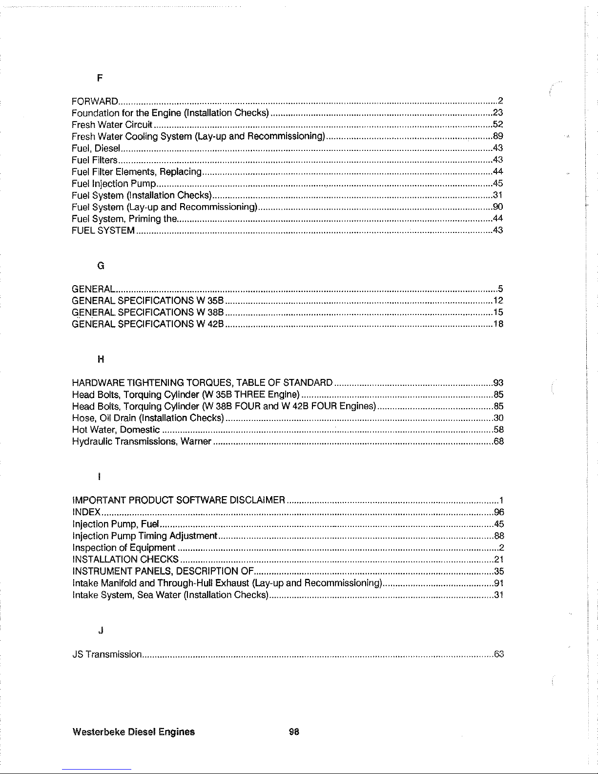
F
FORWARD
...................................................................................................................................................... 2
Foundation for the Engine (Installation
Checks)
........................................................................................
23
Fresh
Water Circuit ......................................................................................................................................
52
Fresh
Water
Cooling System
(Lay-up
and
Recommissioning) ........................................................ , .........
89
Fuel,
Diesel
..................................................................................................................................................
.43
Fuel
Filters
...................................................................................................................................................
.43
Fuel
Filter
Elements,
Replacing ...................................................................................................................
44
Fuel
Injection Pump ....................................................................................................................................
.45
Fuel
System
(Installation
Checks)
...............................................................................................................
31
Fuel
System
(Lay-up
and
Recommissioning) .............................................................................................
90
Fuel
System,
Priming the ............................................................................................................................
.44
FUEL
SYSTEM
.............................................................................................................................................
43
G
GENERAL.
...................................................................................................................................................... 5
GENERAL
SPECIFICATIONS W 35B
..........................................................................................................
12
GENERAL
SPECIFICATIONS W 38B
..........................................................................................................
15
GENERAL
SPECIFICATIONS W 42B
..........................................................................................................
18
H
HARDWARE
TIGHTENING
TORQUES,
TABLE
OF
STANDARD
...............................................................
93
Head
Bolts, Torquing Cylinder
(W
35B
THREE
Engine)
............................................................................
85
Head
Bolts, Torquing Cylinder
(W
38B
FOUR
and W 42B
FOUR
Engines)
..............................................
85
Hose,
Oil
Drain
(Installation
Checks)
..........................................................................................................
30
Hot
Water,
Domestic ...................................................................................................................................
58
Hydraulic Transmissions, Warner ...............................................................................................................
68
IMPORTANT
PRODUCT
SOFTWARE
DISCLAIMER
.................................................................................... 1
INDEX
...........................................................................................................................................................
96
Injection
Pump,
Fuel
....................................................................................................................................
.45
Injection Pump Timing Adjustment .............................................................................................................
88
Inspection of Equipment ............................................................................................................................... 2
INSTALLATION
CHECKS
............................................................................................................................
21
INSTRUMENT
PANELS,
DESCRIPTION
OF
...............................................................................................
35
Intake Manifold
and
Through-Hull Exhaust (Lay-up
and
Recommissioning) ............................................
91
Intake
System,
Sea
Water (Installation
Checks)
.........................................................................................
31
J
JS
Transmission ...........................................................................................................................................
63
Weslerbeke Diesel Engines
98
 Loading...