

Page 1

..,,'
"
}i
";
SERVICE
MANUAL
65A-FOUR
MARINE
.,,--.,26.0
AND
-NET
.
GENERATORS
3,28.5
ENGINE
20.0KW
MOBILE/INDUSTRIAL
and
25.5KW
'
EDER
EDE
D-NET
~
.,F
,:IL
ARINE
PUBLICATION #053017
SECOND
GENERATORS
EDITION
APRIL
2009
WESTERBEKE
WESTERBEKE
MYLES
WEBSITE:
CORPORATION.
STANDISH
INDUSTRIAL
WWW.WESTERBEKE.COM
150
JOHN
PARK'
HANCOCK
TAUNTON
MA
ROAD
02780
Page 2

CALIFORNIA
Exhaust
gasoline
its
constituents)
the
State
cancer,
reproductive
Exhaust
colorless
gasses
gas.
unconsciousness
exposure
can
PROPOSITION
WARNING
gas
from
engines
of
California
birth
defects,
harm.
contain
carbon
and
include:
-Dizziness
-Nausea.
-Headache
-
Weakness
IF
YOU
GET
OUT
seek
until
and
OR
ANYONE
INTO
medical
it
has
been
Sleepiness
THE
attention.
Inspected
65
diesel
and
(and
some
of
are
known
to
to
cause
and
other
AWARNING:
carbon
Monoxide
death.
ELSE
FRESH
Shut
Monoxide,
is
poisonous
Symptoms
-
Throbbing
-
Muscular
-
Vomiting
-Inability
EXPERIENCE
AIR
IMMEOIATELY.
down
and
ANY
the
unit
repaired.
an
odorless
and
of
Carbon
in
Temple{;
Twitching
to
Think
OF
THESE
If
and
symptoms
and
can
cause
Monoxide
Coherently
SYMPTOMS,
persist,
do
not
restart
A
WARNING
should
generator.
WESTERBEKE
MONOXIDE
of
your
obtainable
DECAL
be
fixed
to a bulkhead
also
DETECTORS
vessel.
at
They
your
is
provided
by
near
recommends
in
the
living/sleeping
are
inexpensive
local
marine
Engines & Generators
WESTERBEKE
your
engine
installing
CARBON
quarters
and
easily
store.
and
or
Page 3

SAFETY
INSTRUCTIONS
ImOOUCTION
Read this
safety
numual
carefuily.
Most
accidents
are
caused
by
failure
to
follow
fundamental
rules
and
precau-
tWns.
Know
when
dangerous
condiJions
exist and
take
the
necessary
precautitJns
to
protect yourself, your
personnel,
and your
machinery.
The
following safety
instructWns
are
in
compliance
with
the American Boat and
Yacht
Council
(ABYC)
standards.
PREVENT
ELECTRIC
SHOCK
A
WARNING:
lID
not
touch
AC
eltN:tricaJ
COIIIIIIetIons
willie
tJIJfIiOtlIs
mnning,
01
wilen
connected
to
sholtJ
"...
LetIIaI
milage
Is
PItJSBIIt
at
tIrtJstJ
connections!
•
Do
not
operate this machinery without electrical
enclosures
and
covers
in
place.
• Shut off electrical power before accessing electrical
equipment.
•
Use
insulated
mats
whenever
working
on electrical
equipment.
•
Make
sure your clothing
and
skin
are
dry,
not
damp
(particularly shoes)
when
handling electrical
equipment.
•
Remove
wristwatch and all jewelry
when
working
on
electrical equipment.
•
Do
not
COMect
utility shore power
to
vessel's
AC
circuits, except
through
a ship-to-shore double
throw
tIansfer switch. Damage
to
vessel's
AC
generator
may
result if this procedure
is
not
followed.
• Electrical shock results
from
handling a charged
capaci-
tor.
Discharge capacitor
by
shorting terminals
together.
PREVENT
BURNS -HOT
ENGINE
A
WARNING:
lID
not
touch
hot
BOgin.
palls
01
BIhaust
srsItJm
compoOtlnis. A mnning
engine
gets
,."
"",!
•
Always
check the engine coolant
level
at
the
coolant
recovery
tank.
I A
WARNING:
StBam
can
couse
injury
01
death!
• In case of
an
engine overheat,
allow
the engine
to
cool
before touching the engine or checking
the
coolant.
PREVENT
BURNS -FIRE
A
WARNING:
FiltJ
can
caUBB
injury
01
deathl
• Prevent
flash
fires.
Do
not
smoke
or
permit
flames
or
sparks
to
occur near
the
carburetor,
fuel
line,
filter,
fuel
pump,
or
other potential sources of spilled
fuel
or
fuel
vapors.
Use
a suitable container
to
catch
all
fuel
when
removing
the
fuel
line,
carburetor,
or
fuel
filters.
•
Do
not
operate
with
a Coast
Guard
Approved
flame
arrester
removed.
Backfire
can
cause
severe
injury
or
death.
•
Do
not
operate with
the
air cleanerlsilencer
removed.
Backfire
can
cause severe
injury
or
death.
•
Do
not
smoke
or permit
flames
or sparks
to
occur
near
the
fuel
system.
Keep
the compartment and
the
engine/generator clean
and
free
of debris
to
minimize
the
chances
of
fire.
Wipe
up
all
spilled
fuel
and
engine
oil.
•
Be
aware
- diesel
fuel
will
bum.
PREVENT
BURNS -EXPLOSION
A
WARNING:
Explosions
f~m
fuel
vapors
can
couse
Injury
01
d.atIr!
• Follow re-fueling safety instructions.
Keep
the
vessel's
hatches closed
when
fueling.
Open
and ventilate
cabin
after fueling. Check below
for
fumes/vapor
before
run-
ning
the
blower.
Run
the
blower
for
four
minutes
before
starting your
engine.
•
All
fuel
vapors
are
highly
explosive.
Use
extreme
care
when
handling
and
storing
fuels.
Store
fuel
in a well-ven-
tilated area
away
from
spark-producing equipment
and
out of
the
reach
of children.
•
Do
not
fill
the
fuel
tank(s)
while
the engine
is
running.
•
Shut
off
the
fuel
service
valve
at
the
engine
when
servicing
the
fuel
system.
Take
care
in
catching
any
fuel
that
might
spill.
DO
NOT
allow
any
smoking,
open
flames,
or
other
sources
of
fire
near
the
fuel
system
or
engine
when
servic-
ing.
Ensure proper ventilation exists
when
servicing
the
fuel
system.
•
Do
not
alter or
modify
the
fuel
system.
•
Be
sure
all
fuel
supplies
have
a positive shutoff
valve.
•
Be
certain
fuel
line
fittings
are
adequately tightened
and
free
of
leaks.
•
Make
sure a
fire
extinguisher
is
installed
nearby
and
is
properly maintained.
Be
familiar
with
its
proper
use.
Extinguishers rated
ABC
by
the
NFPA
are
appropriate
for
all
applications encountered
in
this
enviromnent.
~
WESTERBEKE
Engines & Generators
i
Page 4

SAFETY
INSTRUCTIONS
ACCIDENTAL
STARTING
A
WARNING:
Accidental
starting
can
cause
injury
111
death!
• Disconnect
the
battery cables before
servicIng
the
engine!
generator.
Remove
the
negative
lead
first
and
reconnect
it
last.
•
Make
certain
all
personnel are clear of
the
engine
before
starting.
•
Make
certain
all
covers,
guards,
and
hatches
are
re-
installed before starting
the
engine.
BATTERY
EXPLOSION
A
WARNING:
Battery
explosion
can
cause
injury
at
death!
•
Do
not smoke or
allow
an
open
flame
near
the
battery
being
serviced. Lead acid batteries emit hydrogen,
a.
highly
explosive
gas,
which
can
be
Igmted
by
electrIcal
arcing
or
by
lit tobacco
prodUCts.
Shut off
all
electrIcal
equipment
in
the
vicinity
to
prevent
electrIcal
arcIng
dur-
ing
servicing.
• Never connect the negative (-) battery cable
to
the
posi-
tive (+) connection terminal of
the
starter solenoid.
Do
not
test
the
battery condition
by
shorting
the
terminals
together.
Sparks could ignite battery
gases
or
fuel
vapors.
Ventilate
any
compartment containing batteries
to
prevent
accumulation of explosive
gases.
To
avoid
sparks,
do
not
disturb
the
battery charger connections
while
the
battery
is
being
charged.
•
Avoid
contacting
the
terminals
with
tools,
etc.,
to
prevent
bums
or sparks that could cause
an
explosion.
Remove
wristwatch, rings,
and
any
other jewelry before
handlIng
the
battery.
•
Always
turn
the
battery charger off before disconnecting
the
battery connections.
Remove
the
negatIve
lead
first
and
reconnect
it
last whenservicing
the
battery.
BATTERY
ACID
A
WARNING:
Sulfuric
acid
in
batteries
can
cause
_
injury
or
death!
•
When
servicing
the
battery or checking
the
electrolyte
level,
wear rubber gloves, a rubber apron,
and
eye
protec-
tion.
Batteries
contain
sulfuric
acid
which
is
destructIve.
If
it
comes
in
contact
with
your
skin,
wash
it
off
at
once
with
water.
Acid
may
splash
on
the
skin
or into
the
eyes
inadvertently
when
removing
electrolyte
caps.
TOXIC
EXHAUST
GASES
A
WARNING:
Carbon
monoxide
(CO)
is a deadly
gas!
• Ensure that
the
exhaust system
is
adequate
to
expel
gases
discharged
from
the
engine.
Check
the
exhaust
system
regularly
for
leaks
and
make
sure
the
exhaust
manifold!
water-injected
elbow
is
securely
attached.
• Be
sure
the
unit
and
its
surroundings
are
well
ventilated.
Run
blowers
when
running
the
generator
set
or
engine.
• Don't
run
the
generator set or engine
unless
the
boat
is
equipped
with
a functioning marine carbon
monoxide
detector that complies
with
ABYCA-24.
Consult your
boat
builder or dealer
for
installation of approved detectors.
• For additional information refer
to
ABYC
T-22
(educational information
on
Carbon Monoxide).
A
WARNING:
Carbon
monoxide
(CO)
is
an
Invisible
odorless
gas.
Inhalation
produces
flu-like
symptoms,
nausea
or
death!
•
Do
not
use
copper tubing
in
diesel
exhaust
systems.
Diesel
fumes
can
rapidly
destroy
copper
tubing
in
exhaust
systems.
Exhaust sulfur causes rapid deterioration of copper
tubing
resulting
in
exhaust/water
leakage.
•
Do
not install exhaust outlet
where
exhaust
can
be
drawn
through
portholes,
vents,
or air conditioners. If
the
engine
exhaust
discharge
outlet
is
near
the
waterline,
water
could
enter
the
exhaust
discharge
outlet
and
close
or
restrict
the
flow
of exhaust.
Avoid
overloading
the
craft.
• Although
diesel
engine exhaust
gases
are
not
as
toxic
as
exhaust
fumes
from
gasoline engines, carbon
monOXIde
gas
is
present
in
diesel exhaust
fumes.
Some of
the
symptoms or
signs
of carbon monoxide inhalation or
poisoning
are:
Vomiting
Dizziness
Headache
Nausea
AVOID
MOVING
PARTS
Inability
to
think coherently
Throbbing
in
temples
Muscular twitching
Weakness
and
sleepiness
A
WARNING:
Rotating
parts
can
cause
injury
or
death!
•
Do
not
service
the
engine while
it
is
running.
If
a
situation
arises
in
which
it
is
absolutely necessary
to
make
operat-
ing
adjustments,
use
extreme
care
to
avoid
touching
mov-
ing
parts
and
hot
exhaust
system
components.
-.,y
WESTERBEKE
Engines & Generators
ii
Page 5

SAFETY
INSTRUCTIONS
• Do not wear loose clothing
or
jewelry when servicing
equipment; tie back long hair and avoid wearing loose
jackets, shirts, sleeves, rings, necklaces
or
bracelets that
could
be
caught in moving parts.
• Make sure all attaching hardware is properly tightened.
Keep protective shields and guards in their respective
places at all times.
•
Do
not check fluid levels
or
the drive belt's tension while
the engine
is
operating.
• Stay clear
of
the drive shaft and the transmission coupling
when the engine is running; hair and clothing can easily
be
caught in these rotating parts.
HAZARDOUS
NOISE
A
WARIIIING:
High
nIl.
IBvels
can
cau.
hBaring
/oss1
• Never operate an engine without its muffler installed.
•
Do
not run an engine with the air intake (silencer)
removed.
•
Do
not run engines for long periods with their enclosures
open.
A
WARIIIING:
Do
not
WIlde
In
machlnory
whsn
YIIU
arB
mtmI1IIIt
lIT
physicallt
IncapacltalBd
by
fatiguBI
OPERATORS
MANUAL
Many
of
the preceding safety tips and warnings are repeated
in your Operators Manual along with other cautions and
notes to highlight critical information. Read your manual
carefully, maintain your equipment, and follow all safety
procedures.
ENGINE
INSTAllATIONS
Preparations
to
install an engine should begin with a thor-
ough examination
of
the American
Boat
and Yacht Council's
(ABYC) standards. These standards are a combination
of
sources including the USCG and the NFPA.
Sections
of
the
ABYC
standards
of
particular interest are:
H-2 Ventilation
P-I Exhaust systems
P-4 Inboard engines
E-9
DC
Electrical systems
All installations must comply with the Federal Code
of
Regulations (FCR).
ABYC,
NFPA
AND
USCG
PUBLICATIONS
FOR
INSTALLING
DIESEL
ENGINES
Read the following ABYC, NFPA and USCG publications
for safety codes and standards. Follow their
recommenda-
tions when installing your engine.
ABYC
(American Boat and Yacht Council)
"Safety Standards for Small Craft"
Order
from:
ABYC
15
East 26th Street
New
York,
NY
10010
NFPA
(National Fire Protection Association)
"Fire Protection Standard for Motor Craft"
Order
from:
National
Fire
Protection
Association
II
Tracy Drive
Avon Industrial Park
Avon,
MA
02322
USCG
(United States Coast Guard)
"USCG
33CFR183"
Order from:
U.S. Government Printing Office
Washington, D.C. 20404
-..v:
WESJERBEKE
EngInes & Generstors
iii
Page 6

TABLE
OF
CONTENTS
Testing
for
Overhaul.
...........................................
2
Valves ..........................................................
.41
Engine Compression ...................................... 2 Rocker Arm ................................................ .4 3
Engine
Troubleshooting
.......................................
3 Timing Gear/Crankshaft .............................. 44
General
Description
.............................................
8
Camshaft ..................................................... .45
Cylinder Block ............................................... 8
Idler Gear ................................................... ..46
Half Floating Head Cover ............................. 8
Balancing Shaft .......................................... .47
Cylinder Head ................................................ 8
Piston/Connecting Rod ............................... .48
Piston and Piston Rings ................................. 9 Crankshaft. ................................................... 50
Dynamic Balancer ......................................... 9 Crankpin ......................................................
51
Governor ......................................................
10
Cylinder .......................................................
53
Disassembly
Procedures
.................................
..
11
Oil Pump ...................................................... 53
Generator .....................................................
11
Servicing
S
·fi
t·
peci
ca
Ions
...................................
55
Radiator Models ..........................................
II
Engine
Adjustments
...........................................
61
Propulsion Engines ......................................
II
I'
. T' .
nJectton Immg ..........................................
61
Preparation for Disassembly ........................
11
Valve Clearance ........................................... 62
Remove Interior Components ......................
II
Oil Pressure/Oil Change .............................. 63
Remote
Stop/Start Panel ............................
lla
Fuel
System
.......................................................
64
Assembly
Procedures
.......................................
.
12
Injectors .......................................................
65
Surface Preparation .....................................
12
Injection Pump ............................................. 65
Gasket Information ......................................
12
Glow Plugs .................................................. 65
Engine
Assembly
Instructions
......
.....................
13
Raw
Water
Pump
...............................................
66
Heat Exchanger ...........................................
13
Wiring
Diagram
(#52952)
EDE
...........................
67
Marine Transmissions ..................................
13
Wiring
Diagram
(#54469)
EDER
.......................
67a
Radiators ......................................................
13
Wiring
Diagram
(#31944)
65A·Four
................
67b
Engine Tuning .............................................
13
Specifications·
65A·Four
................................
68
Disassembly/Assembly
(Engine)
........................
14
Specifications·
33Kw
EOE
.............................
68a
Cylinder Head and Valves ...........................
14
Specifications·
28.5Kw
EDER
.......................
68b
Cylinder Head Gasket .................................
16
Generator
Specifications
..................................
69
Governor Housing Assembly ......................
18
Torque
Specifications
.......................................
70
Injection Pump .............................................
19
Special
Tools
.....................................................
72
Thermostat ...................................................
20
Generator
Information
.......................................
83
Injection Nozzle ........................................... 20
Terminal
Board
Connections
.............................
84
Fuel Camshaft and Governor Weight.. ........ 23
Electronic
Regulator
.........................................
85
Injection Pump Assembly ............................ 24
Generator
Servicing
..........................................
87
Water Pump/Oil Cooler ............................... 26
Generator
Troubleshooting
(Chart)
...................
88
Gear Case ..................................................... 27
EDE
Testing
the
Voltage
....................................
89
Oil Screw and Strainer ................................ 29
Internal
Wiring
Schematic
................................
91
Piston and Connecting Rod ......................... 29
Changing
Hertz
and
Voltage
.............................
92
Flywheel and Crankshaft.. ...........................
31
AC
Output
Configurations
.................................
92
Flywheel Housing ........................................ 32
Generator
Parts
Breakdown
..............................
93
Crankshaft. ................................................... 33
Metric
Equivalent
..............................................
95
Starter
Motor
Service
......
..................................
34
Metric
Conversion
Chart
...................................
96
Alternator
Service
.............................................
3 7
Index
...............................................................
97
Servicing
(Engine)
............................................
.40
Cylinder Head ............................................. .40
~
WESTERBEKE
Engines & Generators
1
Page 7

TESTING
FOR
OVERHAUL
HOW
TO
DETERMINE
ENGINE
OVERHAUL
PERIOD
.
Cause
of
Low
Compression
Generally, the time at which
an
engine should be overhauled
is determined
by
various conditions such
as
lowered engine
power output, decreased compression pressure,
and
increased
fuel
and
oil
consumption. The lowered engine power output
is not necessarily due
to
trouble with the engine itself, but
is
sometimes caused
by
injector nozzle wear or injection pump
wear.
The decrease in compression pressure
is
caused
by
many
factors. It is, therefore, necessary
to
determine a cause
or causes
on
the
basis
of
data produced
by
periodic
inspection and maintenance.
Oil analysis on a seasonal basis
is a good means of monitoring engine internal
wear.
When
caused
by
worn
cylinders or piston rings,
the
following
symptoms will occur:
1 Low engine power output
2 Increased fuel consumption
3 Increased oil consumption
4
Hard
engine starting
5 Noisy engine operation
These symptoms often appear together. Symptoms 2
and
4
can result also from excessive fuel injection, improper
injection timing,
and
wear
of
the injectors. They are caused
also by defective electrical devices such
as
the battery,
alternator, starter
and
glow plugs. Therefore it is desirable
to
judge the optimum engine overhaul time
by
the
lowered
compression pressure caused
by
worn cylinders and pistons
plus increased oil consumption. Satisfactory combustion is
obtained only under sufficient compression pressure. If
an
engine lacks compression pressure, incomplete combustion
of fuel will take place even
if
other parts of the engine are
operating properly.
To
determine
the
period of engine
overhaul,
it
is
important
to
measure the engine compression
pressure regularly. At the same time,
the
engine speed
at
which the measurement
of
compression pressure
is
made
should be checked because the compression pressure varies
with engine rpm. The engine rpm
can
be measured at the
front end of the crankshaft.
OVERHAUL
CONDITIONS
Compression pressure tends
to
increase a little
in a new
engine until piston rings and valve seats have been broken
in.
Thereafter, it decreases gradually with the progress of wear
of these parts.
When decrease
of
compression pressure reaches the repair
limit, the engine must
be
overhauled.
The engine requires overhaul when oil consumption
is
high,
blowby evident, and compression valves are
at
minimum or
below.
ENGINE
COMPRESSION
Check the compression pressure.
To
do
this warm
the
engine,
remove all fuel injectors,or glow plugs, disconnect the
fuel
shut-off solenoid wire,
and
install a compression adapter
in
the injector hole or glow plug hole
..
Connect a compression
tester on the adapter
and
crank the engine with
the
starter
motor until the pressure reaches a maximum value. Repeat
this process for
each
cylinder. Look for cylinders
with
dramatically lower compression than the average of
the
others.
COMPRESSION
PRESSURE
(Faclary
Spec.)
at
250
RPM
626
PSI
44
Kgl/cm'
4.32
MPa
ALLOWABLE
LIMIT
al250
RPM
472
PSI
33.2
Kgl/cm'
3.26
MPa
If
a weak cylinder is flanked
by
healthy cylinders, the
problem
is
either valve or piston-related. Check the valve
elearances for the weak cylinder, adjust
as
needed, and test
again.
If
the cylinder
is
still
low,
apply a small amount of
oil
into the cylinder
to
seal the rings, and repeat the test. If
the
compression comes up, the rings are
faulty.
Abnormally high readings on all cylinders indicate heavy
carbon accumulation, a condition that might be accompanied
by high pressures and noise.
NOTE:
In case
of
severe vibrations and detonation noise, the
cause may be fuel injector problems, see
FUEL INJECTORS.
Poor
fuel quality, contaminants and loss
of
po
sitive fuel
pressure to the injection pump will result
in
faults.
TESTING
ENGINE
COMPRESSION
When re-installing the glow use anti-seize compound.
34.3
to
39.2
N·m
Nozzle holder
3.5
to
4.0
kgf·m
25.3
to
2B.9
ft-Ibs
t9.6
to
24.5
N·m
Tightening torque
Over1low pipe nut
2.0
to
2.5
kgf·m
14.5
to
tB.t
ft·lbs
49.0
to
6B.6
N·m
Nozzle holder assembly
5.0
to
7.0
kgl·m
36.2
to
50.6
ft·lbs
Engines & Generators
2
Page 8

ENGINE
TROUBLESHOOTING
The following troubleshooting chart describes certain problems relating
and the recommendations to overcome these problems.This chart may
overhaul.
HARO
PROBLEM
STARTING
LOW
CRANKING
1.
Engine
oil
2.
Run·down
3.
Worn
battery.
4.
Battery
5.
Defective
6.
Defective
OEFECTIVE
1.
Air
trapped
2.
Clogged
3.
Low
injection
4.
Inadequate
5.
Injection
6.
Injection
MAIN
ENGINE
1.
low
compression.
a.
Incorrect
b.
Inadequate
c.
Valve
d.
Broken
e.
Compression
f.
Piston
g.
Worn
2.
Burnt
glow
3.
Faulty
glow
4.
Incorrect
5.
Governor
PROBABLE
SPEEO
viscosily
battery.
terminals
loosely
starter.
main
drive
INJECTION
in
fuel
passage.
fuel
filter.
pressure.
spray.
pump
delivering
too
early.
TROUBLES
valve
contact
stem
seized.
valve
spring.
leaks
ring
seized.
piston
ring
plug.
plug
operation.
governor
lever
spring
out
CAUSE
too
high.
connected.
section.
SYSTEM
insufficient
clearance.
of
valve
through
and
cylinder.
position.
of
POSITION
fuel.
seat.
cylinder
head
gasket.
to
engine service, the probable causes of these problems,
be
of assistance in determining the need
VERIFICATION/REMEOY
1.
Replace
engine
oil
with
less
2.
Recharge
3.
Replace
4.
Clean
5.
Repair
6.
Check
1.
Bleed
2.
Clean
3.
Adjust
4.
Clean
5.
Repair
6.
Adjust
2.
Replace
3.
Correct
4.
Set
5.
Correct
terminals
clutch
air
or
injection
or
or
injection
a.
Adjust
b.
Lap
c.
Replace
d.
Replace
•.
Replace
f.
Replace
g.
Overhaul
lever
battery.
battery.
or
replace
from
replace
replace
replace
valve
valve.
glow
lead
wire
to
starting
spring
for
fuel
valve
valve
gasket.
piston
engine.
plug.
and
correct
starter.
disengagement.
system.
filter.
pressure.
nozzle.
injection
pump.
timing.
clearance.
and
valve
spring.
and
piston
connection.
position.
viscous
cables.
guide.
ring.
for
oil.
an
engine
LOW
OUTPUT
LOW
COMPRESSION
INJECTION
1.
2.
3.
INSUFFICIENT
1.
2.
3.
INSUFFICIENT
1.
SYSTEM
Incorrect
Insufficient
Low
injection
Airtrapped
Clogged
filter.
Contaminated
Clogged
aireleaner.
injection
injection.
pressure.
FUEL
in fuel
fuel
INTAKE
OUT
OF
timing.
system.
tank.
AIR
~
ADJUSTMENT
WESTERBEKE
Engines & Generators
3
See
1.
2.
3.
1.
2.
3.
1.
HARD
Adjust
Repair
Check
Check
Clean
Clean
Clean
STARTING
injection
or
replace
injection
and
retighten
or
replace
tank.
or
replace
timing.
injection
nozzle
connector.
filter.
air
cleaner.
and
pump.
adjust
pressure.
(continued)
Page 9

ENGINE
TROUBLESHOOTING
PROBLEM
PROBABLE
CAUSE
VERIFICATION/REMEOY
LOW
OUTPUT
(c.nI.)
OVERHEATING
1.
Low
coolant
level.
1.
Add
coolant.
2.
Loose
V·belt.
2.
Adjust
or
replace
V·belt.
3.
Incorrect
injection
timing.
3.
Adjust
injection
timing.
4.
low
engine
oil
level.
6.
Add
engine
oil.
EXCESSIVE
OIL OIL
LEAKAGE
CONSUMPTION
1.
Defective
oil
seals.
1.
Replace
oil
seals.
2.
Broken
gear
case
gasket.
2.
Replace
gasket.
3.
loose
gear
case
attaching
bolts.
3.
Retig
hten
bolts.
4.
Loose
drain
plug.
4.
Retighten
plug.
5.
Loose·oil
pipe
connector.
5.
Retighten
oil
connections.
6.
Broken
rocker
cover
gasket.
6.
Replace
gasket.
7.
Loose
rocker
cover
attaching
bolts.
7.
Relighten
attaching
bolts.
OIL
LEVEL
RISING
1.
Incorrectly
positioned
piston
ring
gaps.
1.
Correct
ring
gap
positions.
2.
Displaced
or
twisted
connecting
rod.
2.
Replace
connecting
rod.
3.
Worn
piston
ring.
3.
Replace
ring.
4.
Worn
piston
or
cylinder.
4.
Replace
piston
and
rebore
cylinder.
OIL
LEVEL
FALLING
1.
Oelective
stem
seal.
1.
Replace
stem
seal.
2.
Worn
valve
and
valve
guide.
4.
Replace a valve
and
valve
guide.
EXCESSIVE
FUEL
ENGINE
BODY
TROUBLES
CONSUMPTION
1.
Noisy
knocking.
1.
See
KNOCKING.
2.
Smoky
exhaust.
2.
See
SMOKY
EXHAUSr
3.
Moving
parts
nearly
seized
or
excessively
worn.
3.
Repair
or
replace.
4.
Poor
compression.
4.
See
LOW
COMPRESSION;
HARO
STARTING.
5.
Improper
valve
timing.
5.
Adjust.
6.
Improper
valve
clearance.
6.Adjust.
INSUFFICIENT
INTAKE
AIR
1.
Air
intake
obstructed.
1.
Remove
obstruction.
NOZZLE
TROUBLES
1.
Seized
nozzle.
1.
Replace.
2.
Worn
nozzle.
2.
Replace.
IMPROPER
FUEL
Replace
with
proper
fuel.
FUEL
LEAKS
Find
fuel
leaks.
SMOKY
EXHAUST
WHITISH
OR
PURPLISH
1.
Excessive
engine
oil.
1.
Correct
oil
level.
2.
Excessive
rise
of
oil
into
combustion
chamber.
a.
Poor
piston
contact.
••
Check.
b.
Seized
piston
ring.
b.
Replace
or
clean.
c.
Excessive
piston-to-cylinder
clearance.
c.
Replace
or
correct.
(contmued)
Engines & Generators
4
Page 10

ENGINE
TROUBLESHOOTING
PROBLEM
SMOKY
EXHAUST
ABNORMAL
OR
NOISE
(cant.,
SOUND
WHITISH
3.
4.
BLACKISH
1.
2.
3.
CRANKSHAFT
1.
2.
3.
CONNECTING
1.
2.
3.
OR
d.
Worn
e.
Low
f.
Excessive
Injection
timing
Insufficient
OR
Engine
body
a.
Poor
b.
Improper
Insufficient
Improper
Badly
worn
Badly
worn
Melted
bearing.
Worn
connecting
Worn
crankpin.
Bent
connecting
PURPLISH
valve
engine
compression.
compression.
intake
fuel.
AND
bearing.
crankshaft.
ROO
PROBABLE
stem
oil
viscosity.
oil
pressure.
is
too
DARK
GRAYISH
troubles.
valve
air
MAIN
AND
rod
rod.
CAUSE
(cant.,
and
valve
guide.
late.
clearance.
(air
cleaner
clogged).
BEARING
CONNECTING
big
end
bearing.
ROD
BEARING
3.
Adjust.
4.
See
2.
Clean
3.
Replace
1.
Replace
2.
Grind
3.
Replace
1.
Replace
2.
Grind
3.
Correct
VERIFICATION/REMEDY
d.
Replace.
e.
Replace.
I.
Correct.
LOW
COMPRESSION;
a.
See
LOW
COMPRESSION;
b.
Adjust.
air
cleaner.
with
proper
fuel.
bearing
and
crankshaft.
bearing
and
check
bearing.
crankshaft.
bend
or
replace.
grind
HARD
STARTING.
HARD
crankshaft.
lubrication
STARTING.
system.
ROUGH
OPERATION
PISTON.
PISTON
1.
Worn
cylinder.
2.
Worn
piston
3.
Piston
seized.
4.
Piston
seized
VALVE
MECHANISM
1.
Worn
camshaft.
2.
EXcessive
3.
Worn
timing
INJECTION
1.
2.
GOVERNING
1.
2.
PUMP
Uneven
injection.
Inadequate
SYSTEM
Governor
Fatigued
lever
governor
PIN.
AND
pin.
and
ring
valve
clearance.
gear.
SYSTEM
injection
nozzle
malfunctioning.
spring.
PISTON
worn
spray.
RING
or
damaged.
1.
Rebare
2.
Replace
3.
Replace
4.
Replace
1.
Replace.
2.
Adjust.
3.
Replace.
1.
Adjust
4.
Replace
1.
Check
2.
Replace.
cylinder
piston.
piston
piston
injection
injection
governor
to
oversize
and
and
or
replace
nozzle.
shaft
rebore
rings.
and
and
replace
cylinder.
parts.
correct
piston.
operation.
(continued)
"MJI"
WESTERBEKE
Engines & Generators
5
Page 11

ENGINE
TROUBLESHOOTING
PROBLEM
KNOCKING
INTERMlmNT
EKHAUST
OVERHEATING
SOUND
ENGINE
KNOCKS
1.
Main
engine
a.Overheated
b.Carbon
2.
Too
early
3.
Too
high
4.
Improper
KNOCKING
1.
Poor
compression.
2.
Injection
3.
Improper
a.
Poor
b.
Poor
c.
After-injection
d.
Nozzle
1.
Fuellilter
2.
Fuel
pipe
3.
Water
mixed
1.
V-belt
slackening
2.
Damaged
3.
Lack
of
coolant.
4.
Low
oil
level
5.
Knocking.
6.
Moving
parts
7.
Defective
PROBABLE
WITHOUT
troubles.
cylinder.
deposits
injection
timing.
injection
pressure.
luel.
WITH
DARK
pump
malfunctioning.
nozzle.
spray.
chattering.
drip.
needle
valve
clogged.
sucks
air.
in
fuel
or
water
pump.
or
poor
seized
thermostat.
MUCH
in
cylinder.
SMOKE
seized.
slippery
oil
quality.
or
damaged.
CAUSE
SMOKE
with
oil.
a.
See
b.
Clean.
2.
Correct.
3.
Correct.
4.
Replace
1.
See
LOW
2.
AdjusVRepair.
a.
Clean
b.
Repair
c.
Repair
d.
Replace.
1.
Clean
or
2.
Retighten
3.
Replace
fuel.
1.
Adjust,
replace
2.
Replace.
3.
Add.
4.
Add
or
change.
5.
See
KNOCKING.
6.
Replace.
7.
Replace.
VERIFICATION/REMEOY
OVERHEATING;
with
proper
COMPRESSION;
or
replace
or
replace
or
replace
replace.
pipe
jOints
or
fuel.
nozzle.
nozzle.
nozzle.
or
clean.
LOW
OUTPUT.
HARD
replace
STARTING.
pipe.
LOW
OIL
HIGH
OIL
RAW
WATER
FUEL
MIXING
LUBE
OIL
WATER
LUBE
OIL
PRESSURE
PRESSURE
IN
CYLINDERS
WITH
MIXING
WITH
1.
Worn
2.
Relief
3.
Clogged
4.
Diesel
1.
Wrong
2.
Relief
1.
Fail
1.
Injection
2.
Injection
3.
Deficient
1.
Delective
2.
Cylinder
Bearings.
valve
mallunction.
oil
cooler.
dilution
type
of
valve
defective
of
syphon
pump
pump's
nozzle
head
block/cylinder
of
the
oil.
oil.
valve
or
broken.
plunger
injection.
gasket.
exhaust
is
worn.
head
flawed.
system
1.
Engine
overhaul
replace
bearings.
2.
Overhaul
oil
pump.
3.
Repair.
4.
Injection
pump
repair.
1.
Replace.
2.
Replace.
..
1.
Clean
1.
Rebuild,
2.
Replace.
3.
Replace
1.
Replace.
2.
Replace.
out,
inspect
replace.
nozzle
exhaust
system,
replace.
(continued)
Engines & Generators
6
Page 12

ENGINE
TROUBLESHOOTING
Problem
Probable
Cause
Veriftcatlon/Remedy
Exhaust
smoking
problems
1.
Blue
smoke.
1.
Incorrect
grade
of
engine
oil.
1a.
Crankcase
is
overfilled
with
engine
oil
(oil
is
blowing
out
through
the
exhaust).
2.
White
smoke.
2.
Engine
is
running
cold.
28.
Faulty
injector
or
incorrect
injector
timing.
3.
Black
smoke.
3.
Improper
grade
of
fuel.
3a.
Fuel
burn
incomplete
due
to
high
back
pressure
in
exhaust
or
insufficient air
for
proper
combustion
(Check
for
restrictions
in
exhaust
system;
check
air
intake.).
3b.lmproperly
timed
injectors
or
valves
or
poor
compression.
3 •.
lack
of
air -check
air
intake
and
air
filter.
Check
for
proper
ventilation.
3d.
Overload.
LCD
QISPLAYS
No
LCD
Display
1.
Check
battery.
1.
Battery
on.
2.
20
amp
breaker
off.
2.
Turn
breaker
on.
Oil
Pressure
1.
Oil
level
low/oil
leak.
1.
Check
oil
level,
add
oil
and
repair
leaks.
2.
Lack
of
oil
pressure
2.
Test
oil
pressure.
If
OK,
test
oil
pressure
sendor,
inspect
oil
filter,
inspect
oil
pump.
3.
Ground
connection.
3.
Check
ground
connection.
4.
Faulty
control
module.
4.
Inspect
all
the
plug
connections/replace.
Coolant
Temperature
1.
Check
system
coolant
level.
1.
Add
coolant.
Check
for
leaks.
2.
Check
water
pump
drive
belt.
2.
Adjust
belt
tension,
replace
belt.
3.
Faulty
Temp
sensor.
3.
Check
sensor/replace.
4.
Ground
Connection.
4.
Check
ground
circuit.
5.
Faulty
control
module.
5.
Check
plug
connectionslreplace.
Exhaust
Temperature
1.
Check
sea
water
flow.
1.
Inspect
thru
hull
fitling,
hose
and
strainer.
Correct
as
needed,
2.
Faulty
exhaust
temp
switch.
2.
TesVreplace.
3.
Ground
Connection.
3.
Check
ground
circuit.
4.
Faulty
control
module.
4.
Check
plug
connections.
5.
Sea
water
pump.
5.
Inspect
impeller/replace.
Battery
Voltage
1.
Check
alternator
drive
belt.
1.
Adjust
tension/replace
if
worn.
2.
Check
charge
voltage.
2.
Check
excitation.
replace/repair
alternator
3.
Check
battery
connections.
3.
Check + and -cables
from
battery
to
engine.
4.
Faulty
control
module.
4.
Check
plug
connectionslreplace.
Generator
Voltage
1.
Check
AC
voltage
output.
1.
Adjust
voltageitroubleshoot
generator
for
cause.
2.
Faulty
control
module.
2.
Check
plug
connectionslreplace.
Generator
Frequency
1.
Check
engine
speed.
1.
Adjust.
2.
Check
fuel
supply.
2.
Inspect
filters/replace
filters.
Test
fuel
pump
operation.
3.
Amperage
load.
3.
Check
load
with
amprobe.
LED
Display
-
1.
Compartment
ambient
temperature
1.
Ventilate
compartment.
edges
tum
pink.
too
high.
-.¥
WESTERBEKE
Engines & Generators
7
Page 13

I
GENERAL
CYLINDER BLOCK
This engine employs separate type crankcases the crankcase 1 with combustion parts and the
crankcase 2 which supports the crankcase 1 and
reduces noise.
Since it is a hanger type, you can
and disassemble it. The cylinder is a linerless
ble
type which enables good cooling operation, less
strain and good abrasion resistance.
easily assem-
HALF-FLOATING HEAD COVER
DESCRIPTION
The rubber packing
cover 0.5
arrangement
. cylinder head.
mm
or
helps
is
so
off
reduce
RUBBER
PACKING
fitting
the
in
to
maintain
cylinder head. This
noise
coming
the
from
CYLINDER
HEAD
head
the
COVER
U---OIL
PAN
CYLINDER HEAD
This engine employs a three valve system: two
inlet valves and double ports, and one exhaust
valve which produces good inlet inertia to
improve combustion efficiency and
efficiency.
combustion chamber with
grooves.
Besides the
employs the forced cooling method between
valves to eliminate heat distortion, thus enabling
durable
It
also employs a new unique
multiple injection
conventional cross port system, it
and reliable configuration.
volumetric
En'glnes & Generators
8
Page 14

GENERAL
DESCRIPTION
PISTON
This engine employs the E-TVCS VERSION-II
so
that
top
bustion efficiency than the conventional
The profile and the offset
optimized
the
heat
Three rings are installed
piston. The top ring is made
get
It
is
against heavy load. At the Sliding part, a
special piston ring which is conformable to the
cylinder wall is employed. The second ring is
chrome-plated on the
is
an undercut ring to prevent the holding
The oil ring (3) has chamfered contact faces
and an expander ring, which increase the
pressure
wall.
Several
help heat dissipate and to prevent scuffing.
AND
PISTON
the improved combustion surface at the
of
the piston enables more complete com-
to
reduce piston slap. The oil
small end
load of the piston.
more reliability than the chrome plated ring.
a keystone type ring to provide durability
of
the connecting rod reduces the
of
the oil ring against the cylinder
grooves are cut
RINGS
models.
of
the piston are
jet
at
in
grooves
of
nitrizing steel to
peripheral surface and it
on
the topland to
in
the
of
oil.
TOP
RING
~~~G
OILRING
DEPRESSION
I I \
r;
I \ -
~
....
;:.
PISTON
~~~_77GROOVES
DYNAMIC
Engines are sure to vibrate due to the
reciprocation
cylinder engines are much less prone to cause
vibration than four
any engine has many moving parts
to its pistons and cannot be
from vibration.
The
balanced weight
second inertia mentioned above and reduce
vibration.
BALANCER
of
the pistons. theoretically, three
cylinder engines. However,
four
cylinder engine is fitted with
on
the crankcase to absorb the
in
addition
completely free
PISTON
TOPLAND
BALANCER
SHAFT
-.v
WESTERBEKE
Engines &
Generators
9
Page 15

GENERAL
GOVERNOR
This
mechanism maintains engine speed at a
constant
provides
engine speed by
rate.
This
controls the fuel injection rate at all speed
ranges (from
utilizing the balance between the flyweight's
centrifugal
A
is independent
rotates
providing better response to
delivering greater engine output.
level even under fluctuating loads and
stable idling and regulates maximum
controlling the fuel injection
engine uses a mechanical governor that
idling to maximum speed)
force and spring tension.
governor
at
shaft for monitoring engine speed
of
the injection pump shaft and
twice the speed
of
conventional types,
load fluctuation and
by
DESCRIPTION
SPRING
PIN
(6)';~~~~Q\;;;;~-.T'J'!:="'5---
SPEEO
CONTROL--ttt+~r
LEVER
FORK
LEVER 1 (7)
IDLE
ADJUSTING
BOLT-'Oll~::h;",,<
FORK
2
LEVER
GOVERNOR
SPRING
(4)
At
Start
The
stop
solenoid (energized to run type) is
powered to
release the stop lever.
As no centrifugal force is applied to the
flyweight
(1), low tension
of
the start spring (2)
. permits the control rack to move to the starting
position,
start
At
Idling
Turn
supplying the amount
the
engine.
the
speed control lever (3) clockwise to
of
fuel required to
idle the engine. It tensions the governor spring
(4) to
pull
the
fork lever
2.
When the fork lever 2 is pulled, it moves the
torque spring pin (6) and fork
direction
of
the arrow A to restrain the weight.
lever 1 (7)
in
the
In combination with the start spring tension, it
is
balanced with the centrifugal force
flywheel
• At rated speed with full load and overload
As
speed to high
weight
to maintain idling.
the speed control lever
speed,
the governor spring tension
is
changed
increases to compress the torque spring
fork lever 1
The fork lever 2
limiting bolt
When the engine
speed decreases
weight decreases.
fork lever 1
The control
fuel supply
centrifugal force of
in
the
to
keep
in
the
rack
to
increase
direction
moves
rated
rotation
is
overloaded,
and
the
Then
the torque
direction
moves
in
the
output.
the
flywheel weight
of
the
arrow
until it
reaches
and
centrifugal force of flywheel
of
arrow
the
direction that increases
It
is
of
the
from
the
middle
and
move
A.
the
output
rated
output.
the
engine rotating
spring
moves
A.
balanced with the
to
produce low-
the
speed output (torque output).
the
NO·LOAD
ROTATION
OUTPUT
TORQUE
SPEEO
LIMITING
LIMITING
BOLT
BOLT
CONTROL
• To stop engine
When
tension
of
the
the
the stop lever
the
To
lever
arrow B
stop
to
the
which
the
left.
FLYWEIGH1l1
LEVER
stop
solenoid
moves
)
131-H\+l
solenoid
is
the control
stops
engine
manually,
/ll-l.l..>..w.J--
is
released,
the
engine.
turned
the
rack
move
off,
the
rod
extrudes
in
the
direction
the
external stop
CONTROL
RACK
spring
and
of
'9Y'
WESTERBEKE
Engines & Generators
10
Page 16

DISASSEMBLY
PROCECURES
GENERATOR
Unplug
side
the
photo or mark all connections
Remove
intake
elbow
Drain the engine
Carefully support
from
Additional generator information will be found
GENERATOR
and
disconnect
and inside of the control box
control box off the
the
air hose between
box.
Separate the exhaust hose
and
disconnect the fuel supply
the engine.
section of this manual.
oil
and
and
the
electrical connections
AC
generator end.
the
coolant from the engine.
then unbolt
to
allow
to
ensure proper
the
control
at
and
the
generator backend
COOLANT
19MM
for
NOTE:
box
the water injected
return lines.
HEX
on
the out-
the
removal of
Properly
reconnecting.
and
the
engine
in
the
DRAIN
PLUG
PROPULSION
Unplug
transmission
Detach
from the engine.
NOTE:
the
the
Label any
ENGINE
instrument panel wiring harness. Drain
fluid
and
oil
cooler hoses
lines,
the transmission
and
hoses or cables
oil
cooler hoses.
unholt the transmission
as
you
separate
the
them.
TRANSMISSION
If
the
transmission
inspected. Flush out and pressure test the
replace the coolant hoses. Inspect
linkage
the transmission and change the transmission fluid.
For
units
contact the transmission manufacturer for the location
and
transmission service
Operator's
DAMPER
BOLTS
is
not being rebuilt,
and
the
propeller shaft coupling. Clean
and
maintenance refer to the
mannal,
To
rebuild a transmission
it
should
oil
cooler
lubricate
be
the
gear shift
and
visually
and
repaint
of
RADIATOR
Drain the coolant using
of
the
brackets and lower the mounting frames. Remove the
radiator and
Remove the DC charging alternator. Remove the four
bolts securing
and
remove the
remove
MODELS
the
radiator. Unbolt the radiator from
set
aside for servicing.
the
fan
to
the fresh water pump pulley
fan
and pulley. Unbolt the
it.
petcock found at
the
side support
fan
guard
the
base
and
''''',"<I'T
PLATE
BROKEN
PREPlUtAil(IN
• Clean
• Do not remove
• When disconnecting sensor wires, label and
• Perform disassembly
•
• Pay attention
or
disassembly.
Keep disassembled parts
necessary.
from intrusion of dust and dirt.
Parts
must
which
they
parts
must
its
component,
reproduced
parts for their positions or directions. Put on marks, if
necessary,
FOR
DISASSEMBLY
wash
the
engine exterior.
or
disassemble the parts that require
in
a proper order using proper
in
order. Apply
Take
special care
be
restored
were
removed
be
set
aside
so
that
at
assembly.
to
marks on assemblies, components
to
aid assembly.
to
their
at
disassembly.
separately
the
same
to
keep
respective
in
groups,
combination
the
"u<DAMPER
FOR
SPRINGS
tape
oil
when
fuel system parts
components
This
means
each
or
set
WEAR
the
from
that
marked
can
be
and
AND
no
ends.
tools.
all
for
DISASSEMBLY/ASSEMBLY
RADIATOR
~
WESTERBEKE
Engines & Geners/ors
11
• Carefully check each part or component for
faulty condition during removal or cleaning. The part
tell you how
it
acted
or
what
was
abnormal about
any
sign of
will
it
more
Page 17

DISASSEMBLY
PROCEDURES
REMOVE
With the transmission/generator/radiator separated from the
engine. begin the following step by step procedure to
disassemble the exterior parts.
NOTE:
1.
Remove
Label the wires
2 Witb the hoses disconnected, remove the thermostat
housing
sender
3. Remove
(Generators
4.
Remove
hreaker/pre-heat solenoid mounting
Remove
S.
Remove
bracket. Make note
6. Remove
engIne Hywheel
7. Remove the engIne mounted
complete with its
WATER
Generators
8. Remove
one end
removed
EXTERIOR
Mount the engine securely
the
start
and
housing gasket, leaving the
and
switch in place if applicable.
the
magnetic pick-up from the bell housing
COMPONENTS
on
motor, drive belt,
and
cables.
only).
the
Hywheel
the
engIne
the
oU
the
transmission
PUMP for parts breakdown.
heD
housing
back
plate.
filter,
oU
cooler,
of
the hose arrangements.
damper
(Marine
Engines).
adapter
mounting plate. See
raw
only)
the
engine
of
each hose connected to the part being
(Marine
heat
Engines
exchanger.
and
Generators
a suitable engine
and
the alternator.
temperature
and
the circuit
bracket
oU
hoses
and
mounting
plate from the
water
pump,
(Marine
If
Engines
possible. leave
only)
.
stand.
RAW
and
9.
Remove the exhaust components from the exhaust
manifold
a) Remove the exhaust elbow (if applicable) from the
lower surface of the manifold. Clean
and
cracks
b) Remove the exhaust nipples, elbows
the manifold.
c)
Remove the water connectors from the ends of the
manifold. Be
arrangement
d) Examine
and
e) Flush
passage. Set aside
10. Remove the coolant circulating pump. Refer
COOlANT PUMP ASSEMBLY.
11.
Remove the
manifold.
Prepare
12.
defects. Replace as needed.
sure
to note the
of
each for
aU
parts
for defects, corrosion
replace as needed.
out
the coolant recovery tank
to
re-instaD on the boat.
air
intake silencer
to disassemble the main engine.
proper
proper
and
and
inspect for
and
plugs from
location
alignment.
and
and
clear its hose
the intake
and
wear
to
....
WESTERBEKE
Engines & Generators
11a
Page 18

ASSEMBLY
PROCEDURES
GENERAl
Surface
Thoroughly remove
application
Check
is
to
greases and
surfaces.
remains
INFORMATION
Preparation
surfaces
to
ensure
that
be
applied
Do
in
foreign
not
the
bolt
is
forget
ASSEMBLY
•
Wash
all
parts,
etc.
with cleaning solvent
• Always
you
job.
•
Use
of
• Be sure
torques
•
When
must be installed.
use
tools
understand
only
good
oil, grease or sealant
to
use
are
specified.
the
engine
all
substances deposited
using
a gasket scraper
the
surfaces
flat.
Make sure that there
substances deposited
to
holes.
except
for
that
are
how
to
quality lubricants. Be
a torque
is
assembled,
remove
oil
and
in
good
use
them
to
parts
wrench
to
which
the
seals,
dry
condition
before performing
as
to
tighten
new
on
the
gasket
or
wire
brush.
the
silicone
are
no
on
the
old
sealant
O-rings, rubber sheets,
them
with
and
sure
to
apply a coat
specified.
parts
gaskets
and
gasket
oils,
application
that
air
pressure.
be
sure
any
for
which
O-rings
INTERNAL
When
reassembling external or internal
them
so
which
force
that
SNAP
the
is
applied.
sharp
RING.
PLACE
AGAINST
aFFORCE
edge
GREASE
THE
THE
faces
EXTERNAL
SHARP
EDGE
DIRECTION
snap
against
the
SNAP
rings,
position
direction
RING
from
Be
aware
of
these
common
problems
assembly.
Insufticlent Lubrication.
reciprocating parts, lightly
except those
fasteners should
high-tech equivalent.
Reversed
all
thermostats
Mechanical damage.
torque sequences and
Exceptions
fasteners.
latter-mcker shaft fasteners should
small increments,
especially head
assembly,
that
penetrate into
be
orientation. Most
are
asymmetrical.
are
torque-to-yield bolts
The former
working
gaskets,
they
should
Heavily
oil
sealed
with
gaskets,
Run
fasteners
in
three steps-I/Z,
are
torqued
from
might
be
positioned
head
the
Pennatex
the center
also
that
can
oil
sliding
bolts
and
water jacket.
No. Z or
many
down
in
2/3,
and
rocker
as
indicated.
be
brought
bolts
be
damaged during
with
great
occur during
and
other
fasteners,
These
the
bolt
washers,
approved
and
111
arm
shaft
The
down
out.
care.
and
torque.
in
very
Gaskets,
GASKET
The
silicone gaskets
RTV
it
is
gasket.
Too
be
the
a joint,
break while observing
The
vulcanization
gram)
moisture
both
INFORMATION
engine
has
several
100.
To
ensure that
necessary
thin a bead
squeezed out of location causing blocking
fluid
gasket
applicator/tube.
engine
Bead
feed
it
is
in
to
size,
lines.
necessary
material
(RTV)
the
atmospheric
oil
and
areas
where
are
used
such
as
LOCTITE
the
gasket
observe
could
some
precaution
continuity and location
cause
leaks
and
To
eliminate
to
apply
the
used
type
The
coolant assemblies.
correct
in
the
and
RTV
air
the
the
bead
engine
is
supplied
hardens
and
gasket
form-in-place
fully
possibility
can
598
serves
when
are
too
thick a bead
or
evenly
size.
is a room
in a 140z
as
it
reacts
be
used
RTV
or
GE
its
purpose,
applying
very
important.
narrowing of
of
leaks
without a
temperature
(400
with
for
sealing
the
could
from
the
Engines & Generators
12
Page 19

ENGINE
ASSEMBLY
INSTRUCTIONS
ALTERNATOR
When rebuilding the engine. the alternator should be cleaned
and inspected. The housing can be wiped
and the alternator tenninal studs should be cleaned with a
wire brush. Make certain the studs are tight and clean the
wiring
connections that connect to the wiring harness.
Thrn the rotor pulley by hand.
Depending on when the alternator was last serviced. the
brushes may need replacing.
send it to a service shop for testing and overhaul. or refer
the more detailed alternator section in this manual.
HEAT
EXCHANGER
Install the heat exchanger. replace the heat exchanger zinc
and attach new hoses with new clamps to the cooling system.
Refer to the
INSPECTION
off
with a solvent
It
should turn smoothly.
If
the alternator is at all suspect.
to
(MARINE
COOllNG SECTION in this manual for HEAT
ENGINES/GENERATORS)
EXCHANGER service.
MARINE
1. Assemble Ibe
2. Re-install
MOlE:
Drive require oil coolers.
pressure tested and repainted at engine overhaul.
transmission oil cooler hases should also
ReJer
TRANSMISSION
damper
Ibe
marine
correct
amount
of
(MARINE
plate
transmission
fluid. Do
to
not
the
Some transmissions. such as the Borg
Oil
coolers should be
to
the text on HEAT EXCHANGERS.
ENGINES)
flywheel.
and
overfill.
be
inspected.
fill with the
Warner
Velvet
cleaned,
The
RADIATORS
The
radiator, cleaned. flushed, and pressure tested can be
assembled to the generator mounting rails. The fan can be
assembled to the engine.
ENGINE
After re-assembly, the unit must be test run. This will ensure
that the engine/generator operates to its specifications. Fill
the engine cooling system with an antifreeze mixture and the
engine oil sump with lube oil
CH4
1.
2.
3.
4.
5.
6.
7.
8.
Refer
These
Specifications.
and Raw
TUNING
or
CI4
Mount
fuel, elecrtical,
required.
Pre-lube
solenoid/actuator
allow
Start
pressure,
Allow
temperature
adjust
Check
Correct
Propulsion Load
full
After
fasteners
are
protect
the
the
the
the
engine idle speed
unit
test
load
load
tight
as
to
the following pages for details
sections
Water
OPERATION
SEA 15-40.
unit
on a test
exhaust
the
unit
if
not
and
oil
pump
to
unit
and
monitor
water
temperature,
unit
to come
and
check the engine speed. (Propulsion-
for
any
leakage
as
needed.
Check
the
test,
and
and
needed.
also
Torque
Pump.
fuJI
unit
in
gradual
stop
unit
electrical connections to
secure.
Check
include:
Diagrams.
API specifications
stand
aud
make
and
coolant connections
already
intermittently
prime
up
no
done
the oil passages.
for
proper
DC
charge, etc.
to
normal
for
smoothest operation).
of
oil, fuel
load
rpm.
steps
114, 112,
an
allow to rest.
wire hose challing
of
Wiring
Diagrams,
Starter
Motor.
of
CF,
CG4.
the
needed
as
or
disable
crank
operation
operating
or
make
the
the unit to
coolant.
3/4
and
Check
sure
and
like oil
all
they
sub-assemblies.
Engine
Alternator
fuel
Engine
Inspect the engines flexible mounts. Replace any that show
signs
complete overhaul. all four should be replaced.
Mounts
of
wear, rust, or splits in the rubber isolators.
In
a
Engines & Generators
13
Page 20

DISASSEMBLY
I
ASSEMBLY
Cylinder Head and Valves
Cylinder Head Cover and Nozzle Holder
1.
Remove the injection pipes
2.
Remove the glow plugs.
3.
Remove the nozzle holder assembly
4.
Remove the heat seal.
5.
Remove the head cover.
(When reassembling)
• Check to.
see
that the cylinder head cover gasket is not
defective.
•
Be
sure to replace the heat seal.
• TIghten the head cover mounting bolts to specified torque.
• Mount the return fuel check valve with the I mark in the
direction
Tightening
of
flow back to the taok. t
Cylinder head cover
mounting
Injection
nut
torque
NOlzle holder assembly 5.0 to 7.0 kgf·m
Overflow pipe assembly
retaining nut
Glow Plug 2.0 to 2.5 kgf-m
Nozzle Heat Seal Service Removal Procedure
•
IMPORTANT
•
Use a plug
bigger
1.
Drive screw driver lightly into
(phillips) screwdriver
than
the
heat seal hole (Approx. 6 mm, 1/4 in.).
2. Turn screw driver three or four times each way.
3. While turning the screw driver, slowly pull the heat seal out
together with the injection nozzle gasket. .
If the heat seal drops, repeat the above procedure. Hmit seal
(4) and injection nozzle gasket
injection nozzle is removed for cleaning or for service.
screw
pipe
(1)
and
overflow pipes.
(4)
and copper gaskets.
6.9 to 11.3
0.7
5.1
retaining
the
(3)
22.6 to 36.3 N·m
2.3 to 3.7 kgf·m
16.6 to 26.8
49.0
36.2
19.6 to 24.5
2.0
14.5
19.6 to 24.5 N·m
14.5 to
that
has
heat seal hole.
must be changed when the
N·m
to
1.15 kgf·m
to 8.32 It-Ibs
It-Ibs
to 68.6 N·m
to
50.6 It-Ibs
N·m
to 2.5 kgf·m
to
18.1
It-Ibs
18.1
It-Ibs
a dia.
which
is
COPPER
GASKETS
HEAT
o
GLOW
NOZZLE
SEAL
HEAD
COVER
_",IN,JEClrION
PIPE
PIPE
LIFTING
CAUTION:
ENGINES
OUT
THE
ASSEMBLED
EYE
IF
THERE
LIFTING
THIS
STUO.
BOTTOM
BOLT.
THRU
IS
REASON
EYE,
00
SIMPLY
THE
STUD
THE
WATER
TO
NOT
ATTEMPT
REMOVE
THE
IS
PERMANENTLY
JACKET.
REMOVE
Engines & Generators
TO
NUT
THE
TAKE
AND
14
PHilLIPS
INJECTION
NOZZLE
GASKET
=:r.:3::s..\..L=-
HEAT
SEAL
(3)
(4)
Page 21

DISASSEMBLY
I
ASSEMBLY
Rocker Arm
1. Remove
2. Remove
3. Detach the bridge arm.
(When
When putting the push
•
their
•
IMPORTANT
•
After
valve
Tightening torque 5.0 to 5.7 kgf·m
.
Cyfinder Head and Tappet
1.
Loosen the hose clamp and remove the by-pass hose
2.
Disconnect the fuel pipe
3.
Remove ttie
4. Remove the cylinder head screw
remove the cylinder head.
5.
Remove the cylinder
6.
Remove the tappets from the crank case.
(When
• Replace
• Before installing the tappets apply engine oil thinly around
them.
• When mounting the gasket, set it
care not to mount it
•
The cylinder head should
• Take care for handling the gasket not to damage
• Install the cylinder
• Tighten the cylinder
(18) aiter applying engine
•
Be
Clearance".
• It
is not necessary
running the engine for
•
IMPORTANT
• When replace the piston, piston pin bush, connecting rod
or
thickness
"Selecting
•
NOTE
• Mark
interchanging.
Tightening torque 10.0 to 11.0 kgf·m
and
Push
Rod
the
rocker arm
the
push rods.
reassembling)
ends are properly engaged with the
reassembling the rocker arm, be sure
clearance.
Rocker
screw
IN. / EX.
reassembling)
the head gasket
sure
to
adjust the valve clearance.
crankpin
the
bearing, select the cylinder head gasket
to
meet with the top clearance refer
Cylinder
cylinder
Cylinder head mounting
screw
(1)
as
a unit.
rods
onto
the tappets, check
arm
bracket
(3)
first
Manifold.
head
gasket.
with
a new
reversely.
be
free of scratches
head.
head
screw gradually
oil.
to
retighten the cylinder head screw aiter
30
minutes.
Head Gasket" .
number
to
49.0 to 55.9
36.2 to 41.2 ft-Ibs
and
then the
in
the order
one.
to
the knock
the tappets to prevent
98.1 to
72.3 to 79.6 It-Ibs
tappet
to
N·m
fuel
filter.
of
(18)
pin
and
it.
in
the orderof
See
107.9
N·m
to
see if
recess .
adjust the
to
(1),
and
hole.
Take
dust.
(1)
the "Valve
to
the
to
-L---V:li
.
014
018
.
no no
17
0
010
o-clo..
0013
06.
o
0
05
CYLINDER
PUSH
RODS
TAPPET
03
02
00
d 0 0
0
04
HEAD
TIGHTENING
SEQUENCE
07
8
0
Om
00
0
-
-0
012
_
0/
......
15
16
..
Engines & Generators
15
Page 22

DISASSEMBLY
Selecting Cylinder Head Gasket
• Replacing
1.
Make sure to note the notch (a), (b) or (c) of cylinder head
gasket.
Replace the same notch (a), (b) or (c)
2.
head gasket.
•
Selecting
• Select the cylinder head gasket thickness
top
clearance when replacing the piston, piston pin bush,
connecting rod or crankpin bearing.
1. Measure the piston head's protrusion or recessing from the
crankcase
four pistons) using the dial
Select the suitable cylinder head gasket refer
2.
below.
Notch
01
Cylinder
Head
Gasket
2 notches
(a) 0.0354 in. 0.0315 in. ·0.0028 to
1 notch
(b) 0.0394 in. 0.0354 in. +0.0020 to
wnhout
notch
(c)
~
1.
Remove the valve cap
compressing the
(3).
(When
• Install the intake valve spring with
downward (at the head side).
• Wash the valve stem and valve guide hole, and apply engine
oil sufficiently.
• After installing the valve spring collets, lightly tap the stem to
assure proper fit with a
the
Cylinder
the
Cylinder
cylinder face 4 spots
Thickness of cylinder
head gasket crankcase cylinder
Before
tightening tightening
0.90mm
1.00mm
1.05mm
0.0413 in.
reassembling)
After
0.80mm
0.90mm
0.95 mm +0.20
0.0374 in. +0.0059 to
valve spring
head Gasket
as
the original cylinder
Head Gasket
to
per
each piston (average
!Jauge
(1)
plastic hammer.
as shown.
Piston
Head's
recessing from
(average of 4 pistons)
V3300·E2B
·0.07
to ·0.27
+0.049
mm
+0.0019 in.
+0.050
to
+0.149
mm
+0.0058 in. ·0.0020 in.
+0.150 to
mm
+0.0078 in.
and the valve spring collets (2)
(4)
with the valve spring retaine;
its
small-pitch end
meet with the
to
protrusion
the
V3300·T·E2B
·0.151mm
·0.0110 to
·0.0059 in.
·0.15 to
·0.051 mm
·0.0059 to
-0.0510
·0.0019 to
a
in.
I
the table
or
level
of
face.
to
Dmm
ASSEMBLY
of
PROTRUSION
RECESS
II
.
I-
@(~
(2)
(1)...-"~(3)
~(7)~(4)
~ ~
J1 J1
...__-:::O..,;,-"'l!Th,...
(a) 2 Notches
(b) 1
Notch
(c)
Without
Flywheel
MEASURING
SPOTS
Notch
Side
PISTON
, .
@@
,
f-::~
(1)
Valve Cap
.
(2)
Valve Spring Collet
(3)
Valve Spring Retainer
(4)
Valve Spring
(5)
Valve Stem Seal
(6)
Valve
(7) Arm Bridge
Engines & Generators
16
t
(10)
INSTALL
PITCH
END
WITH
DOWN
LARGE
SMALL
SMALL
PITCH
PITCH
Page 23

DISASSEMBLY
I
ASSEMBLY
7. Slide off the governor connecting
injection pump
8. For convenient sake, temporarily hook the start spring
rack pin
9. Remove the governor housing mounting screws.
10.
Detach the governor housing assembly (8) from the injection
pump unit.
(When reassembling)
• When reassembling the inside parts, put the oil
part
slightly.
After sliding on the governor connecting
•
tighten the nut with the specified torque with using the jig for
keeping the governor connecting
Replacing Injection
After tightening the
•
• Check the movement of control rack of injection pump
assembly by the stop lever .
•
NOTE
• When installing the governor housing assembly to the
injection pump unit,
When linking the governor connecting rod to the rack pin
•
of injection pump, use the jig for keeping the governor
connecting rod
be stuck, and causes
may
or hunting of governor.
Pump Assembly.)
Tightening
torque
assembly.
hole of the governor connecting rod.
Pump
Assembly).
nut,
hook the start spring on the rack pin.
be careful not to damage O.ring.
horizontal. Otherwise the control rack
to
Governor
mounting
Anti-rotation
housing
screw
nut
rod
(7) from the rack pin of
on
the
on
each inside
roa
to the rack pin,
rod
horizontal. (See the
be difficult to start the engine
(See the Replacing Injection
9.B
to
11.3
N·m
1.00
to
1.15 kgf·m
7.23
to
B.32 ft·lbs
2.B
to
4.0
N·m
0.29
to
0.41
kgf·m
2.1
to
3.0 ft·lbs
GOVERNOR
CONNECTING
ROD
(7)
GOVERNOR
HOUSING
ASSEMBLY
(81
~;o-===ffFt':~-Hr--RACK
PIN
(51
1...".,'1
GOVERNOR
/
CONNECTING
ROD
(71
Engines & Generators
17
'%;))
~0f~~~
O·RING
CONNECTING
START
SPRING
ROD
(6)
(7)
Page 24

DISASSEMBLY
4.
Temporarily tighten the injection pump gear mounting nut
hand.
5.
Fix the injection pump unit
mounting nut to the specified torque.
S.
Take off the fuel
plugs (1) for plugging.
7.
Loose the injection pump unit mounting nuts
the injection timing.
8. Moving the injection pump unit clockwise (viewed from gear
case side), align the injection timing marks
pump unit and
9.
Tighten the injection pump unit mounting nut
specified torque.
10.
Reconnect
replace
gear
11.
Remove
12. Check the injection timing. (See the "Injection Timing".)
13.lf the injection timing is
to (12) again.
TIghtening torque
the
cover
the flywheel lock.
cam
on
the
the lubricating oil pipe (3) and
injection pump
of
the injection pump unit.
Injection
mounting
Injection
mounting
and
tighten the injection pump gear
shaft lock screws
gear
case.
unit
not
within the specification, repeat
pump
gear
nut
pump
unit
nut
(2)
(S)
support and the
73.6 to 83.4
7.5 to 8.5 kgf·m
54.2 to
6t.5
17.7 to 20.6 N'm
t.8
to
2.1
13.0 to 15.2 h-Ibs
kgf·m
and
(4)
on
N·m
h-Ibs
the
I
ASSEMBLY
by
tighten the
for aligning
injection
(4)
to the
(7)
INJECTION
GEAR
---""-'
,....-<,----.~_...,.,..,.u"'1
PUMP
(5)
Governor Housing Assembly
1. Remove the injection pump unit from the engine. (See the
"Injection Pump Unit".)
2.
Remove the governor lubricating pipe.
3. Remove the stop solenoid
4. Detach the sight cover
5.
Unhook the start spring
pump assembly.
S.
Remove the nut.
..
(3)
from the injection pump unit.
(4)
from the rack
pin
(5)
of injection
.NOTE
• Be careful
not
to
drop
the
nut
inside.
Engines & Generators
18
~~~
~~J.I.-:;\~
Jm}ctfil~:m=~TIIMINGIMARKS
r--T~(ji'tl-MnolNTlINn
NUTS
(6
(4
Page 25

DISASSEMBLY
I
ASSEMBLY
Injection
(Removing the fuel injection
1.
2.
•
IMPORTANT
•
•
NOTE
• When the already existing align marks align with each
3.
4.
5.
•
NOTE
• Never overtighten the lock screws when they have come
• Use
6.
•
NOTE
• Be careful
7.
8.
9.
Injection Pump Unit
(Reassembling the fuel injection pump unit)
1.
Pump
Unit
pump
Detach
gearcase.
Place
the
look
marking pen
tooth of the
gears in mesh
other, there
Unscrew
Tighten
contact with the
not
Tighten the lower
into contact with
into contact with the cam shaft. Otherwise the injection
pump unit
recommended for best
constructed as shown in figure (a).
loosen
specific gear puller, take
Disconnect
Loosen
Remove
injection pump unit.
Place
the
the
gear cover for
the
piston
compression
for
the align mark on the idle .gear
the
the
move
any
of
a socket set screw (dog point type) in
the
the
the
the
piston
compression
of
stroke.
or
the like, put
idle gear. This helps to reassemble these
later .
is
no need
two
plugs
upper
fuel
fuel
longer.
fuel
the
itself may get damaged.
injection
not
to
drop
the
lubricating
three injection pump unit mounting
injection pump unit support
of
the
stroke.
the
the
4th
cylinder
Lock the flywheel
to
put
(1)
off
cam
shaft lock screw
cam
shaft.
cam
shaft lock screw
fuel
cam
results. Such screw can be
pump
gear mounting
out
the gear
the key.
oil
pipe.
4th
cylinder
Lock the flywheel
fuel injection
an
the injection pump
shaft .
unit)
pump
unit
from
at
the
top
dead
center
in
place .
2.
Using a white
align mark on the engaged
another align mark.
unit.
until
it
comes
Make
sure the
(5)
at
the
.
(6)
top
cam
(2)
nut.
nut.
and
dead
in
shaft
until
Using
take
place.
does
it
comes
out
center
into
the
the
the
in
SUPPORT
in
~~~lF~U~~~~17t17):::""'PLUGS(l)
(a)
-
~~~----
--1--
B
c
D
A M8 x Pilch 1.25
5 mm dia. (0. I
B
4 mm (0.157 in.)
C
D 45 mm (1.772 in.)
E
10
mm
(0.39
97
in. dia.)
in.)
: Conspicuously Painted
2.
Place the injection
position.
pump gear
3.
install the injection
•
NOTE
• When installing the injection pump unit to the injection
pump
injection pump gear.
Make
(5)
gear, make sure that the key
sure
and
pump
of
aligning
the
idle
pump
gear
gear
unit
to
(5)
back into
the
align marks
2.
the injection
is
fit in the keyway
~
the
gear
case
of
the
injection
pump
gear
(5)
.
of
WESTERBEKE
Engines & Generators
19
Page 26

DISASSEMBLY
I
ASSEMBLY
Thermostat
Thermostat Assembly
1.
Remove
the
thermostat cover mounting
screws,
and
remove
the
thermostat
cover.
2.
Remove
the
thermostat
assembly.
(When reassembling)
• Apply a liquid gasket (Three
Bond
1215
or
equivalent) only at
the thermostat cover side
of
the gasket.
•
Install
the
thermostai
with
its
bleed
hole
facing
towards
the
discharge
opening
of
the
thermostat
housing.
Re-Assemble
and
Test
THERMOSTAT
(~
~J
THERMOSTAT
HOUSING
COVER
Turn
the
cover
back
into
place
and
tighten
the
three
screws.
Do
nol
over-tightenl
Tighten
the
hose
clamp
and
close
the
drains.
Top
off
the
coolant
and
run
the
engine.
CHeck
for
normal
temperature
and
for
any
leaks
around
the
thermostat
assembly
.
TEMPERATURE·
SENSOR
Injection Nozzle
Nozzle Holder
.
THERMOSTAT
ASSEMBLY
SENSOR
1.
Secure
the
nozzle retaining
nut
(7)
with a vise.
2.
Remove
thehozzle holder
(1),
and
take
out
parts inside.
(When reassembling)
• Assemble
the
nozzle
in
clean
fuel
oil.
• Install
the
push
rod
(4),
noting
its
direction.
• After assembling
the
nozzle,
be
sure
to
adjust
the
fuel
injection
pressure.
34.3 to 39.2
N·m
Nozzle
holder
3.5 to 4.0 kgf·m
25.3 to 28.9 «·Ibs
NOZZLE
HOLDER
ADJUSTING
ROO
(4)
PIECE
t-::(.....--NOZZLE
PIECE
t9.6
to 24.5
N·m
Tightening
torque
Overflow
pipe
nut
2.0
to
2.5 kgf·m
14.5 to 18.1
«·Ibs
NUT
(7)
49.0 to 68.6
N·m
Nozzle
holder
assembly
5.0 to 7.0 kgf·m
36.2 to 50.6 «·Ibs
Engines & Generators
20
Page 27

DISASSEMBLY
Governor Fork Lever Assembly
1. Pull off the governor fork lever shaft
(Dia.: 4 mm,
2.
Unhook the governor spring (3)
side.
3. Remove the governor fork
housing (5).
(When reassembling)
• After reassembling the governor housing assembly, check the
movement
control lever and the stop lever.
•
NOTE
• When assembling the inside parts, put the oil on each
Inside part slightly.
•
Be careful not
Boost
Arms
1. Remove the boost actuator (1).
2. Remove the
3. Remove the boost arms (3) and the boost spring (4) from the
pin
(fi).
Tightening
torque
Pitch:
of
III equipped Boost Compensator)
cir-clip (2).
0.7 mm, Length: more than 25
lever assembly from the governor
the governor fork lever assembly, the speed
to
deform the start spring.
Boost
actuator 4.0
(1)
with the extra screw
at
the governor fork lever (4)
39.2
to
45.1
N·m
to
4.6 kgf·m
28.9
to
33.3 ft-Ibs
I
ASSEMBLY
mm).
GOVERNOR
()
(
(4)
\\~
."::J::-
__
IIOOiHACTUATOR
I ·,ClIP
'~~::r==a~f:~lli::=
PIN
(5)
__
BOIOST
nr--Rnln<T
ARMS
SPRING
(1)
(2)
3)
(4)
PIN
(5)
HOUSING
GOVERNOR
SPRING
(5)
,----FORK
t
GOVERNOR
LEVER
FORK
LEVER
SHAFT
r~
I
(4)
.
~
WESTERBEKE
Engines & Generators
21
REMOVING
ARMS
AND
THE
C/R-CLIP
SPRING
BOOST
Page 28

DISASSEMBLY
1.
Remove the speed contra) lever (1) and the return spring.
2.
Remove the governor lever assembly (3) from the governor
housing.
3. Remove the start spring
Stop Lever
1. Remove the stop lever (1) and the return spring.
2.
Remove the stop lever shaft.
'RETURN
SPEED
LEVER
CONTROL
(1)
SPRING
(4) and the stop spring.
I
ASSEMBLY
SPEED
LEVER
CONTROL
(1)
=
b
STOP
SPRING
~
WESTERBEICE
Engines & Generators
22
Page 29

DISASSEMBLY
I
ASSEMBLY
Fuel Camshaft and Governor Weight
1.
Separate the governor housing assembly from the injection
pump unit.
2.
Remove the governor sleeve.
3.
Remove the injection pump assembly.
4.
Remove the cover.
5.
Remove the fuel camshaft lock screws.
6.
Fix
the fuel camshaft with open end wrench
(See the "Injection Pump Unit".)
(4),
and
remove
the governor weight mounting nut and the governor weight (5).
7.
Loosen the fuel camshaft stopper mounting screws and
remove the fuel camshaft stopper (6).
8.
Pull out the fuel camshaft
9.
After removing the bearing's cir-clip
(7)
and bearings
(8)
together.
(9),
press out the
bearings .
•
NOTE
• Do not use the fuel camshaft lock bolts, when removing
the governor weight mounting nut. Otherwise, the
bolts
or
injection pump housing might get damage.
(When
reassembling)
lock
• Press the bearings into the fuel camshaft.
• Set the cir-clip at the gear side's bearing.
• Install the fuel camshaft and bearings to the injection pump
housing.
• Attach the fuel camshaft stopper and tighten the
fuel
camshaft
stopper mounting screws with the specified torque.
• Attach the governor weight
to
the fuel camshaft and tighten the
governor weight mounting nut with specified torque.
Tigntening
torque
Injection
mounting
Injection
mounting
pump
screw
pump
nut
23.510 27.5
2.4
10
17.4 to 20.3
17.71020.6
I.B
10
13.01015.2
2.B
2.1
N·m
kgf·m
ft-Ibs
N·m
kgf·m
ft-Ibs
--------
COVER
BEARINGS
B
~
WESTERBEKE
Engines & Generators
23
GOVERNOR
WEIGHT
(5)
Page 30

DISASSEMBLY/ASSEMBLY
Fuel Camshaft
and
Governor Weight (Continued)
(When reassembling)
•
Fix
the
fuel
camshaft with lock bolts
camshaft
(10)
is
upward.
• Install the injection pump assembly
housing.
• Attach
the
O-ring
and
the cover
mounting screws.
• Install the governor sleeve
• Check the movement
•
NOTE
• Be careful
not
to
damage the O-ring.
• Be careful the direction
•
When
part
Tightening torque
Replacing .Injection
• The Injection
reassembling
slightly.
Fuel camshaft stopper
mounting screw
Governor weight
mounting nut
Pump
pump
to
of
the governor sleeve .
of
inner
Assembly IIf necessary)
can be replaced
whatever position.
,.
1. Disconnect all injection pipes.
2.
Disconnect the fuel pipe
3.
Disconnect the connector
remove the stop
solenoid.
4. Detach the sight cover
5.
Unhook the starter spring
(5)
(2)
(3)
from
(6),
as
the
key
way of fuel
to
the injection pump
and
tighten the cover
the
fuel
camshaft.
the governor sleeve.
parts,
and
fuel overflow pipe.
oil
each
to
9.3 N·m
7.9
0.80
to
0.95 kgf·m
5.8
to
6.9 n-Ibs
to
72.6
62.8
6.4
to
46.3
with
N·m
7.4 kgf·m
to
53.5 n·lbs
the crankshaft in
from the stop solenoid. Then
the injection pump
and
remove the control
unit.
rod
nut.
~./Jii;~_;FUEL
CAMSHAFT
KEY
WAY
(10)
6.
Slide off the governor connecting
injection pump assembly.
7.
Remove the injection pump mounting screws
take out the injection pump assembly .
• NOTE
• Be careful
•
Be
careful
• When taking
not
to
not
to
drop
the anti-rotation nut.
not
to
deform the start spring.
out
the injection pump assembly,
hit
it against the governor connecting rod.
(When reassembling)
• Install the
new
injection pump according
procedure.
rod
(7)
from the
~
rock
pin
of
and
nuts,
and
be
careful
to
the installing
WESTERBEKE
Engines & Generators
24
CONNECTING
-'-----------CONNECTING
ROD
(7)~~-lm""'1
STARTER
SPRING
(6)
~GOVERNOR
ROD
(7)
Page 31

DISASSEMBLY
Installing Procedure of Injection Pump Assembly
1.
Install the fuel injection pump assembly (1) in its unit
see
N·m
N·m
N·m
kgf·m
of
if the fuel
to
the start
hook the governor connecting rod to the rack pin
injection pump assembly.
2.
Place the service jig
fuel injection pump unit.
the
3.
Make sure the permanent magnet at the tip of the service jig is
(3)
in
the stop solenoid mounting hole of
attracted to the governor connecting rod (4). To do this, turn
the jig a
little clockwise and counterclockwise and look into the
fuel injection pump unit sight hole to see if the governor
connecting
4.
Slightly tighten the anti-rotation nut of the governor connecting
rod
(4)
moves right and left accordingly.
rod.
5.
Holding down the service jig (3) by hand, tighten up the anti-
(5)
to
rotation nut
6.
Hook the start spring
the specified torque.
(6)
to the rack
pin.
Installing Procedure (Continued I
1.
Move the stop lever
(1)
and visually check
to
injection pump control rack comes smoothly back
position by the counter force of the start spring.
2.
If the control rack fails to move back smoothly, remove the
nut,
start spring and the anti-rotation
take the above steps
from 2 of the former page again.
3.
Finally fit the sight cover and the stop solenoid back into place.
2.8 to 4.0
Tightening
torque
Anti-rotation
Injection
mounting
Injection
mounting
nut
pump
screw
pump
nut
0.29 to 0.41 kgf·m
2.1
to 3.0 ft·lbs
23.5 to 27.5
2.4 to 2.8 kgf·m
17.4 to 20.3 ft-Ibs
17.7 to 20.6
1.8 to
2.1
to 15.2 ft·lbs
13.0
I
ASSEMBLY
(2),
and
the fuel
JIG
CONNECTING
(4)
SLIDING
POINT
)
Engines & Generators
25
START
RACK
SPRING
(5)
PIN
Page 32

DISASSEMBLY
I
ASSEMBLY
Alternator Drive Pulley
1.
Lock
the
flywheel
in place.
2.
Remove
the
crankshaft
screw.
3.
Draw
out
the
drive
pulley.
(When reassembling)
255.0
to
274.6
N·m
Tightening
torque
Crankshaft
screw
26.0
to
28.0 kgf·m
188.1
to
202.5 ft·lbs
Alternator Drive Fan Pulley
RADIATOR
MODELS
1.
Lock
the flywheel
in
place.
2. Remove the crankshaft
screw.
3. Draw out the drive
fan
pulley.
Water
Pump and Oil Cooler
Water Pump
1. Remove the pipe band and the water
pipe_
2.
Remove the water pump
..
(When reassembling)
• When mounting the water pump, take
care
not to forget
mounting the
O-ring and not to let it out of position.
Oil Cooler
1. Remove the water pipe.
2.
Remove the oil filter cartridge (2) and the oil cooler joint screw.
3.
Remove the oil
cooler.
39.2
to
44.1
N·m
Tightening
torque
Oil
cooler
joint
screw
4.0
to
4.5 kgf·m
28.9
to
32.5 ft·lbs
COOLER
OIL
FILTER
(2)
Englne~
& Generators
26
WATER
PIPE
ORIVE
PULLEY
CRANKSHAFT
SCREW
/,0'//-<1>.
-WATER
PUMP
Page 33

DISASSEMBLY/ASSEMBLY
Gear Case
Gear Case Cover
1.
Remove the gear case cover.
(When reassembling)
• Confirm that the liquid gasket coating surface
dust and
oil in order to maintain sealing effect.
• Carefully apply the adhesive evenly. Refer to the illustration .
•
NOTE
• When mounting the adhesive-applied parts, take care to
fit
them
to
the mating parts.
• Assemble the adhesive-applied parts within ten minutes.
• Apply a liquid gasket (Three Bond 12170) to the gear case
cover.
23.5
2.4
17.4
Tightening torque
Gear
case
mounting screw
cover
Relief Valve
1.
Remove the relief valve retaining screw.
2.
Remove the relief valve (2), the spring (3) and the packing.
Tightening torque
Relief valve retaining
screw
68.6
7.0
50.6
to
27.5
to
2.8
to
20.3 h-Ibs
to
78.4
to
B.O
to
57.9 h-Ibs
is
free
N·m
kgf·m
N·m
kgf·m
of
water,
,/,LIUIUIU
GASKET
Idle Gear and Camshaft
1.
Remove three set screws of the idle gear and draw out the idle
gear
1,
2.
2.
Remove two set screws of the camshaft stopper
the camshaft.
(When reassembling)
• Set the crankshaft at the top dead center of
cylinder and the camshaft key to the top position and align the
marks of
Refer
idle gear 1
to
the illustration .
a.nd
idle gear 2
• Mount the injection pump gear
case.
CamShaft
Tightening torque
Idle
screw
set screw
gear mounting
and
No.
to
assemble them.
(1)
after installing the gear
23.5
to
27.5
N·m
2.4
to
2.8
17.4
23.5
2.4
17.4
kgf·m
to
20.3 h-Ibs
to
27.5
N·m
to
2.8
kgf·m
to
20.3 «-Ibs
"""
WESTERBEKE
Engines & Generators
27
draw out
1 and 4
INJECTION
PUMP
GEAR
(1)
~
~VALVE
!-SPRING
~PACKING
§-RETAINING
..-i...-IDLE
CRANK
'GEAR
RELIEF
SCREW
GEAR
(2)
(3)
(1)
Page 34

DISASSEMBLY
Idle Gear 1 and Idle Gear 2 (For Balancer Modell
1.
Remove the idle gear mounting screws.
2. Draw out the idle gear (2) and (3).
(When
• When install the idle gear
reassembling)
(2)
and
(3),
cylinder piston at the top dead center
align all mating marks
gears, set the idle gear last.
on
each gear
be
sure
in
compression then,
to
assemble the
to
place the 4th
I
ASSEMBLY
o
MOUNTING
SCREWS
tifTling
CAMSHAFT
Tightening
torque
Idle
screw
gear
mounting
23.5 to 27.5
2.4 to 2.8 kgf·m
17.4 to 20.3 ft·lbs
N·m
~
Camshaft and Balancer Shaft (For Balancer Model)
1.
Remove the camshaft set screws and draw out the camshaft.
2.
Remove the balancer shaft 1 set screws and draw out the
balancer shaft
3.
Remove the balancer shaft 2 set screws and draw out the
balancer shaft
(When
reassembling)
• When. install the balancer shaft 1 and
4th
cylinder piston at the top dead center
1.
2.
2,
be sure to place the
in
compression then,
align all mating marks on each gear to assemble the timing
gears, set the
Tightening
torque
idle gear last.
Camshaft
Balancer
set
shaft
screw
set
screw
23.5 to 27.5
2.4 to 2.8 kgf·m
17.4 to 20.3 ft·lbs
23.5 to 27.5
2.4 to 2.8 kgf·m
17.4 to 20.3 It·lbs
N·m
N·m
CRANK
GEAR
BALANCER
SHAFT
1
BALANCER
2
v
o
o
Plate (Gear Case)
1.
Remove the three plate mounting screws. Detach the plate.
(When
reassembling)
• Apply Three Bond 12170 adhesive or equivalent over the
shaded zones
sandwiched between the crankcase and
Be sure to fix the O-rings.
•
Tightening
LIQUID
GASKET
torque
on
both sides of the gasket that will be
plate.
Plate
mounting
screw
23.5 to 27.5
2.4
to
17.4 to 20.3 ft·lbs
LIQUID
GASKET
N·m
2.8
kgf·m
I!ngfnes & Generators
o
o
GEAR
CASE
PLATE
28
Page 35

DISASSEMBLY/ASSEMBLY
Oil Pan and Oil Strainer
the
1. Unscrew
2.
Unscrew
strainer
oil pan mounting screws and remove the oil
the oil strainer mounting screw, and remove the oil
(2).
(When reassembling)
• Install
• Apply liquid
shown.
• Confirm
dust
• Carefully apply the adhesive evenly .
• NOTE
the
oil strainer, using care not to
gasket (Three Bond 1217D) to the oil pan
that
the liquid gasket coating surface is free of water,
and oil in
order
to maintain sealing effect.
damage
the.
• When mounting the adhesive-applied parts, take care
fit
them
to
the mating parts.
• Assemble the adhesive-applied parts within ten minutes.
• To avoid uneven tightening, tighten mounting screws
diagonal order from the center.
• After cleaning the oil strainer, install it.
• Attach
the
the
oil pan with
air
suction side.
its
central drain plug facing toward
pan.
O·ring.
as
to
in
OIL
STRAINER
OIL
LIQUID
GASKET
PAN
o
PISTON AND CONNECTING
Connecting
1.
Remove
cap.
Remove
2.
Rod
Cap
the
connecting rod screws (1) from connecting rod
the connecting rod caps.
(When reassembling)
• Align
•
•
• Fit
Tightening torque
the
marks (a) with each other. (Face the marks toward
the
injection pump.)
Apply
engine oil to the connecting rod screws and lightly screw
it in
by
hand, then tighten it to the specified torque.
If
the
connecting rod screw won't be screwed
clean
the
threads.
If
the
connecting rod screw is still hard to screw in, replace
When
marks
to
toward
the
using
the
existing crank pin bearing again, put tally
on
the crank pin bearing and the connecting rod
keep
their positioning.
the
crank pin bearing in
the connecting rod, and the non-grooved side toward
cap.
Connecting
rod
ROD
place:
screw 8.0
its centrally groove side
78.5
57.9
to
to
8.5
to
in
83.4
N·m
kgf·m
61.5 ft-Ibs
smoothly,
it.
in
order
CONNECTING
ROD
SCREWS
(1)
WRENCH
•
~
WESTERBEKE
Engines & Generators
29
ALIGN
(a)
Page 36

DISASSEMBLY
I
ASSEMBLY
Pistons
1.
Turn the flywheel and set a piston
to
the top dead center.
2. Pull out the piston upward by lightly tapping it
from
the
bottom
of the crankcase with the grip of a hammer.
(When reassembling)
• Before inserting the piston into the cylinder, apply enough
engine oil to the cylinder.
• When inserting the piston into the cylinder, face
the
mark
on
the connecting rod
to
the injection pump .
•
IMPORTANT
• Do
not
change
the
combination
of
cylinder and piston.
Make
sure
of
the
position
of
each
piston
by
marking. For
example,
mark
"1"
on
the
No.1
position.
• When
inserting
the
piston
into
the cylinder, place the gap
of
the
compression
ring 1
on
the
opposite side
of
the
combustion
chamber and stagger the gaps
of
the
compression
ring
2 and
oil
ring marking a right angle
from
the
gap
of
the
compression ring 1.
•
Carefully
insert
the.
pistons
using
a piston ring
compressor
(1). Otherwise,
their
chrome-plated section
may
be
scratched, causing
trouble
inside the liner.
Piston Ring
and
Connecting
Rod
1.
Remove the piston rings using a piston ring tool.
2.
Put the
fan
shaped concave
(8)
on
the piston
as
shown.
3.
Remove the piston
pin
(1),
and
separate the connecting
rod
(7)
from
the
piston.
(When reassembling)
• Be sure to fix the crankpin bearing and the connecting
rod
are
same I.D. colors.
• When. installing the ring, assemble the rings sa that the
manufacture's mark
(12)
near the gap faces the top of the
piston.
• When installing
the
oil
ring onto the piston, place the expander
joint (10)
on
the
opposite side of the oil ring
gap.
• Apply engine
oil
to
the piston
pin.
• When installing the piston
pin,
immerse the piston
in
80°C
(176
of)
oil
for
10
to 15 minutes and insert the piston
pin
to the
piston.
(6)
(A)
(8)
Second
Rlnl!l
(C)
011
Ring Gap
(D)
Piston
Pin Hole
,
CONCAVE
(e)
(a) 0.79 red. (45 j
(B)~
• Assemble
the
piston to the connecting rod with
the
aligning the
(A)
Connecting Rod
1.0.
Color:
/
direction of
the
fan
shaped concave
(8)
of piston head and the Blue
or
without
color 0
mark
(9)
of
connecting
rod.
(B) Crankpin Bearing
1.0.
Color:
'
• The end faces of the oil ring
are
plated with hard chrome.
In
Blue
or
without
cOlor~-
Oil
RING
putting the piston into
the
cylinder,
be
careful not to get the
oil
.
/GAP
ring scratched by the cylinder.
Use
the piston ring fitter to
~~r:n~~
y -
tighten up the oil ring.
If
the ring's planting is scratched, it may
~
t t
k
th
I
· d
II
. . t
bl
MARK
THE
SAME
NUMBER
ON
ge
s uc
on e cy
In
er
wa
,causing a serious
rou
e.
THE
CONNECTING
ROD
AS
THE
.
PISTON
SO
AS
NOT
TO
CHANGE
THE
COMBINATION
-..y:
WESTERBEKE
. Engines & Generators
30
MTGS.
MAR
(12)
Page 37

DISASSEMBLY
I
ASSEMBLY
Flywheel and Crankshaft
Flywheel
1.
Install the flywheel lock
not turn .
•
NOTE
•
Do
not
use an impact wench. Serious damage will occur.
2. Detach
3. Remove the flywheel.
the
flywheel
(When reassembling)
• Apply ergine
oil
to
the
• Before fitting the flywheel
oil, dust and other foreign substances
• The flywheel
and
the
position. Make sure they
Tightening torque
Flywheel
Bearing Case Cover
•
NOTE
• Before disassembling, check the side clearance
crankshaft. Also check
1.
Remove the bearing
2.
Screw two removed screws into
case cover
to
remove
(When reassembling)
•
IMPORTANT
• In case
installing
install
of
replacing the oil seal, use caution when
the seal in the bearing case cover as not to
it
tilted. The seal should
• Confirm that the liquid gasket coating surface is free
•
water,
Apply
dust
and oil
liquid gasket (Three Bond 12170) to the bearing
case cover as shown.
• Before installing the bearing case cover I
assembly,
lube the seal and be careful not to damage the
seal while installing the assembly.
Install
position
the bearing case cover I oil seal assembly to
the casting mark "UP" on
• Tighten the bearing case cover mounting screws with
even force on the diagonal
•
NOTE
• When mounting the adhesive-applied parts, take care to
fit
them to the mating parts.
• Assemble the adhesive-applied parts within ten minutes.
Tightening torque
Bearing
mounting
so
that the flywheel does
screws.
flywheel
crankshaft
screw
case
screws.
and
the
crankshaft together, wipe
off
their
are
fitting together
are
tightly fit
it
during reassembly.
over
mounting screws.
and
98.110 107.9
10.0 to 1 t
72.3 to 79.6 «-Ibs
the
screw
drive
hole
mating
the
N·m
.0
kgf·m
(3)
it.
be
flush with the cover.
in
order to maintain sealing effect.
it
upward.
line .
case
screw
cove'r
23.5 to 27.5
2.4 to 2.8 kgf·m
17.4 to 20.3 «-Ibs
N·m
faces.
in
just
bolts.
of
bearing
oil
one
seal
of
of
TOP
MARK
UP
TWO
SCREW
HOLES
(3)
LIQUID
GASKET
Engines & Generators
31
Page 38

DISASSEMBLY
I
ASSEMBLY
Flywheel Housing
1.
Remove
the
flywheel housing.
(When
reassembling)
•
Tighten
the
flywheel housing mounting screws with
even
force
on
the diagonal line.
• Make sure
the
crank cases 1
and
2 are clean. Install them
in
position, referring
to
the flywheel housing's contoured face.
Flywheel housing
77.5
to
90.2
N·m
Tightening torque
mounting screw
7.9
to
9.2
kgf·m
57.1
to
66.5 «·Ibs
Crankcase 2
1.
Remove the crankcase 2.
(When reassembling)
•
IMPORTANT
• Make sure
the
crankcase 1 and 2 are clean.
•
Apply
liquid
gasket (Three
Bond
12170)
to
the crankcase
2
as
shown.
•
Tighten
the crankcase 2
mounting
screws
with
even
force
on
the
diagonal line.
•
Confirm
that the
liquid
gasket coating surface is free
of
water,
dust
and oil
in
order
to maintain sealing effect.
• Carefully
apply
the
adhesive evenly.
•
NOTE
• When
mounting
the
adhesive-applied parts, take care to
fit
them
to the mating parts.
• Assemble the adhesive-applied parts
within
ten minutes.
Crankcase 2 mounting
Tightening torque
screw
Crankcase 1 and Crankcase 2
(When
reassembling)
49.0
to
55.9
N·m
5.0
to
5.7 kgf·m
36.2
to
41.2 «·Ibs
• Match the crankcase 1
and
2,
referring
to
the
flywheel
housing's contoured face.
• Tighten the crankcase 2 mounting screws loosely.
• Tighten
up
the jig to the specified torque same
as
the
flywheel
housing screw. This helps
to
minimize
the
level difference
between
the
crankcase 1
and
the
crankcase 2 (at
the
flywheel
side). Possible gap must
be
0.05
mm
(0.0020
in.)
or smaller.
Crankcase 2 mounting
49.0
to
55.9
N·m
5.0
to
5.7 kgf·m
screw
36.2
to
41.3 It·lbs
Tightening torque
Flywheel housing
77.5
to
90.2
N·m
7.9
to
9.2
kgf·m
mounting screw
57.1
to
66.5 ft·lbs
~
WESTERBEKE
Engines & Generators
32
[/0
0
0 0
°
SIT
'1
/~
~
o
Sil
}(r9J
~
1=
'fA,-
0
0
f-
°
fir
1\
l=
•
0
0
0 0
~
co:,":::>
,
,
~
CRANKCASE
2
,0
0
0
0"l
;J
\..
/
\..0
~
,
~]
0
)(,
f-n
0
1-
U~
-
b
)
0
0 0
Jf~
)(
~-'O\_.
0
0
i5'J
.<.J J
CRANKCASE
1
GAP
FLYWHEEL
HOUSING
Page 39

DISASSEMBLY
I
ASSEMBLY
Crankshaft
1.
Remove the main bearing case.
2.
Remove the crankshaft.
(When
reassembling)
• Reassemble
the main bearing case having the same number
as the one engraved on the crankcase, and set the casting
mark
"F
/ W SIDE"
on
the main bearing case facing towards
the
flywheel side.
• Reassemble the thrust bearing (2), with the oil groove facing
outside, into both side of the fourth main bearing case.
•
Apply
oil to the main bearing case screws and tighten them
to
the specified torque .
Main
bearing
case
137.3 to 147.1
N·m
Tightening
torque
14.0 to 15.0 kgf·m
screw
101.3 to 108.5 «-Ibs
/:
~:a;;t~~~~~;:~;2:,-)FOURTH
MAIN
,
EARING
CASE
THRUST
BEARING
(2)
~
--.v-
WESTERBEKE
Engines & Generators
33
1\
.;..;:.!---CRANKCASE 2
JIG
~CRANKCASEI
(21
Page 40

STARTER
MOTOR
SERVICE
Disassembling
1.
Disconnect the solenoid switch.
2.
Remove the two through screws 9 ) and the
two
brush
rear end frame (13) and the brush holder.
3.
Disconnect
(11). Remove also the
{he armature.
4.
Remove the set
planetary
5.
Take out the shaft assembly. Take note of the
position
•
IMPORTANT
•
Before
yoke
and
• Take
•
•
NOTE
• Do
(When
•
note
setup
Apply
and
Apply grease (DENSO.CO.
indicated
bolt.
grease
ball
not
damage
reassembling)
Motor
holder lock screws. take out the
the armature
of
gears and another packing.
of
the lever.
disconnecting the yoke,
the
front bracket.
of
the
to
.
in
the
packings (8), the four
positions
the gears, bearings, shaft's sliding part
to
the brush and commutator.
illiJstration.
(10)
ball (7) from the tip
and the yoke
of
the set
No.
50
put
or equivalent)
tally marks on the
of
of
GEAR
ASSEMBLY~
packings and the
to
the
..
parts
_.-?
Gear
Front Bracket
Solenoid
Overrunning Clutch
Internal Gear
Planetary Gear
Sail
SOLENOID
SWITCH
rl'-\ll.'I'I''''-""''
FRONT
BRACKET
Switch
'~~~.':,~:~
fi~\i~
ARMATURE
FOUR
PLANETARY
GEARS
(10)
Set of Packings
Through Screw
Armature
Yoke
Brush
Holder
Rear End Frame
BAL~(7)
Commutator and Mica
1.
Check the contact face
the
commutator
2. Measure the commutator
several points.
3.
If
the minimum
armature.
4.
If
the
difference
correct the commutator
5.
Measure the mica undercut.
6.
If the undercut
saw blade and chamfer
Commutator
Mica
0.0.
undercut
with
emery paper
0.0.
is
of
the
is
less
than
Factory spec.
Allowable limit
Factory spec.
Allowable limit
less
of
the
commutator for
if
it
0.0.
with
an
than
the
allowable
O.D.'s exceeds
on a lathe
the
the
segment edges.
to
the
allowable limit, correct
wear,
and
is
slightly
outside micrometer
factory specification.
32mm
1.2598
31.4
1.2362
0.50
0.0197
0.20
0.0079 in.
worn.
limit,
replace
the
allowable limit,
in.
mm
in.
to
0.80
mm
to
0.0315
mm
in.
it
grind
with
at
the
a
SEGMENT~OEPTH
CORRECT
~
INCORRECT
~MICA
OF
.;
-
MICA
-..yo"
WESTERBEKE
Engines & Generators
34
Page 41

STARTER
MOTOR
SERVICE
Brush Wear
1.
If
the contact face of the brush is dirty or dusty,
clean
it with
emery paper.
2.
Measure the brush length (A) with vernier calipers.
3.
If the length is less than
the
allowable limit, replace
the
yoke
assembly and brush holder.
Factory
spec.
18.0mm
0.7086 in.
Brush
length
CA)
Allowable
limit
t t.O
mm
0.433t in.
Armature Coil
1.
Check the continuity across the commutator
and
armature coil
core with an ohmmeter.
2.
If it conducts, replace the armature.
3.
Check the continuity across the segments of the commutator
with an ohmmeter.
4.
If it does not conduct, replace the armature.
Commutator
Infinity
Resistance
Armature
coil
core
Commutator
segment
OQ
Overrunning Clutch
1.
Inspect the pinion for wear or damage.
2.
If there is any defect, replace the overrunning clutch assembly.
3.
Check that the pinion turns freely and smoothly
in
the
overrunning direction
and
does not siip
in
the
cranking
direction.
4.
If the pinion slips or does not rotate
in
the
both directions,
replace the overrunning clutch assembly.
Brush Holder
1.
Check the continuity across the brush holder
and
the
holder
support with an ohmmeter.
2.
lfit
conducts, replace the brush holder.
Resistance
Brush
holder
-Holder
support
Infinity
Engines & Generators
35
A
BRUSH
lENGTil
INSPECTING THE ARMATURE COIL
INSPECTING
THE OVERRUNING CLUTCH
Page 42

STARTER
MOTOR
SERVICE
Field Coil
1.
Check the continuity across the lead (1) and brush (2) with
an
ohmmeter.
2.
If
it does not conduct, replace the yoke assembly.
3. Check the continuity across the brush (2) and yoke (3) with an
ohmmeter.
4.
If it conducts, replace the yoke assembly.
Resistance
Lead (1) • Brush (2)
o
~l
Brush (2) • Yoke (3)
1nfinity
Bearing
1. Check the bearing for smooth rotation.
2.
If it does not rotate smoothly, replace it.
SlalQr
1. Measure the resistance across each lead of the stator coil with
an ohmmeter.
2.
If the measurement
is
not within factory specification, replace
it.
3. Check the continuity across each stator coil lead and core with
an ohmmeter.
4.
If infinity is not indicated, replace it.
I
Resistance
I
Factory
spec,
I
Less
than
1.0
n
Engines & Generators
36
Page 43

DESCRIPTION
The stator is
rectifier package
converts the
battery charging
Power
alternator
package contained
These alternators produce a rated output of
rated output
!pm at
alternators are
range of
connected
AC
to the regulator
is
provided
is
achieved
an
ambient temperature of 75'F (23.8'C). The
designed
-40'
to
to
a three-phase,
which
contains
generated
and
accessories,
and
by
the
in
the
alternator.
at
approximately 6000 alternator
to
operate
212'F (-40'
in
the
field
to
six
the
stator
field
diode
lOO'C).
full-wave
diodes.
to a DC
of
the
(or
in
an
ambient temperature
INSPECnDN
When
rebuilding
and
inspected. The housing
and
the alternator
wire
brush.
wiring connections that connect
Thm
the rotor
Make
pulley
the
engine,
temninal
certain
by
the
alternator
can
be
studs should
the
studs
to
hand.
It
should tum
wiped
are
tight
the
wiring
be
ALTERNATOR
bridge
The bridge
output
for
integral regulator
diode trio)
50
or
51
amps.
should
be
cleaned
off
with
a solvent
cleaned
with
and
clean
harness.
smoothly.
a
the
SERVICE
FRONT
BRACKET
(1)
60
AMP
ALTERNATOR
CASE
REFER
TO
DIAGRAM
MANUAL
WIRING
CONNECnONS
GROUND
THE
WIRING
IN
THIS
FOR
ALL
REAR
BRACKET
(2)
DISASSEMBLE
Front Bracket
1. Remove the 4 screws.
2.
Separate the fron! bracket (1) and the rear bracket
each other .
•
IMPORTANT
•
Put
a tally
reassembling
Pulley
1.
Hold the rotor (base of the claw)
using a M24 box wrench.
Tightening torque Pulley nul 5.95
Rotor
1.
Remove the 4 screws and detach the bearing retainer.
2. Temporarily install the nut
rotor.
Brush
1.
When the rotor is detached, the 2 brushes are found
out of the shaft hole.
ALTERNATOR
line
on
the
front
them
later.
on
bracket
the pulley screw, and detach the
and
the
rear bracket
in
a vise. Loosen the lock nut
58.3
to
78.9
to
8.05 kgf·m
to
58.2 ft·lbs
43.0
N·m
(2)
to
stretch
from
for
--
-
--
-
REMOVE 4 SCREWS
0-
0-
00-
MOUNTING
SCREWS
Engin'!.s & Generators
37
TWO
BRUSHES
Page 44

ALTERNATOR
Reassembling the Brush
1.
Fit the brush with
when viewed from front.
•
IMPORTANT
• Be
sure
to
keep the 2 brushes deep
Otherwise
into
position.
• Use a 4
Using
•
popping
2. Match the tally line
section.
the
mm
a pin-pointed (2 mm) punch, keep the brushes
out.
3. Tighten the 4 screws, and draw out the pin-pointed punch out
of the brush holder.
Bearing at
1. Lightly secure the rotor (1) with a vise
remove the bearing
Slip Ring Side
rotor
hex.
its
sliding face
and the rear section can
wrench
to
of
the front section with that
(2) with a
push
puller.
in
the
in
the brushes
clockwise direction
the
brush
to
prevent damage. and
not
into
of
holder.
be
filted
place.
from
the rear
SERVICE
TWO
BRUSHES
PUNCH
WRENCH
Bearing
1. Check the bearing for smooth rotation.
2. If
it
does not rotate smoothly, replace it.
SIatQr
1.
Measure the resistance across each lead
an ohmmeter.
2. If the measurement
it.
3.
Check the continuity aoross each stator coil lead and core with
an ohmmeter.
4.
If infinity is not indicated, replace
I
Resistance
is
not within factory specification, replace
it.
I Factory
spec.
of
the stator coil with
I Less than 1.0
(l
ROTOR
BEARING
(2)
MA7CHI!IG
TALLY
LINES
THE
Engines & Generstors
CHECKING CONTINUITY
38
Page 45

ALTERNATOR
BQlQr
1.
Measure
ohmmeter.
2.
If the resistance
3.
Check the continuity across the slip ring and core with
ohmmeter.
4.
If infinity
I
Resistance
Slip Rino
1.
Check the slip ring for score.
2.
If scored, correct with
3.
Measure the
4.
If the measurement is less than the allowable limit, replace il.
Slip ring D.D.
Brush
Wear
1.
Measure the brush length with vernier calipers.
2.
If
the
3.
Make sure that the brush moves smoothly.
4.
If
the
Brush length
the
resistance across
is
not the factory specification, replace
is
not indicated, replace
I
Factory
spec.
an
emery paper or
0.0.
of slip ring with vernier calipers.
Factory
spec.
Allowable
limit
it.
the
slip rings with
12.8
to
3.3
on
a lathe.
22.7
mm
0.894
in.
22.1
mm
0.870 in.
(l
measurement is less than allowable limit, replace il.
brush is defective, replace il.
Factory
spec.
Allowable
limit
18.5 mm
0.728 in.
5.0mm
0.1.97
in.
TESTING
an
it.
an
MEASURING
SLIP
RINGS
MEASURING
BRUSH
LENGTH
Rectifier
1.
Check the continuity across
ohmmeter.
2.
The rectifier is normal if
one direction
IC
Regulator
1.
Check the continuity across
terminal of
2.
The
IC
does not conduct
and
does not conduct
IC
regulator with
regulator is normal if the conducts
in
the reverse direction.
B
E
the
each
diode
the
an
ohmmeter.
diode of rectifier with
in
the rectifier conducts
in
the reverse direction.
"B" terminal
in
...v:
and
the
one
direction
WESTERBEKE
Engines & Generators
an
in
"F"
and
CHECKING
CONTINUITY
B
8
TERMINAL
39
Page 46

-
SERVICING
Cylinder Head
Too Clearance
1.
Remove the cylinder head (remove the cylinder head gasket
completely).
2.
Bring the piston to its top dead center fasten 1.5 mm dia. 5 to
7
mm
long fuse wires to 3 to 4 spots on the piston top with
grease so
as
to avoid the intake and exhaust valves and the
combustion chamber ports.
3. Bring the piston to its middle position, install the cylinder head,
and tighten the
cylinder head screw to specification. (Head
gasket must be changed to new one).
4. Turn the crank shaft until the piston exceeds its top dead
center.
5.
Remove the cylinder head, and measure squeezed fuse wires
for thickness.
6.
If
the
measurement is not within the specified value, check the
oil
clearance
of
the crankpin journal and the piston pin.
0.72
to
0.90
mm
Factory
0.0283
to
0.0354 in.
Top clearance
spec.
Cylinder
head
mounting
98.1
to
107.9
N·m
Tightening
torque
10.0
to
11.0
kgf·m
screw
72.3
to
79.6 ft·lbs
Cylinder Head Surface Flatness
1.
Clean the cylinder head surface.
2.
Place a straightedge on the cylinder head's four sides (A), (B),
(C)
and
(D) and two diagonal (E) and (F) as shown
in
the
figure.
Measure the clearance with a
feeler gauge.
3.
If the measurement exceeds the allowable limit, correct it with
a surface grinder.
• IMPORTANT
•
Do
not
place
the
straightedge
on
the
combustion
chamber.
•
Be
sure
to
check
the
valve
recessing
after
correcting.
Cylinder
head
surface
flatness
Cylinder Head Flaw
Allowable limit
0.05 mm
0.0020 in.
1.
Prepare an air spray red check.(Code No. 07909·31371).
2.
Clean the surface of the cylinder head with the detergent (2).
3.
Spray the cylinder head surface with the red permeative liquid
(1). Leave it five to ten minutes after spraying.
4. Wash away the red permeative
liquid on the cylinder head
surface with the detergent (2).
5.
Spray the cylinder head surface with the white developer (3).
6.
If
flawed, it can be identified
as
red marks.'
~~~WESTERBEKE
Engines & Generators
40
3EEABAB1P056A
A
E
F
c o
B
Ilil!mll
IDi
s:m:r
illIl:IJIl
Ac-AA
Ie-AS
A!i;f
8
~
~
Page 47

SERVICING
Valve Recessing
1.
Clean the cylinder head, the valve face and
2. Insert the valve into the valve guide.
3.
Measure the valve recessing with a depth gauge.
If the measurement exceeds the allowable limit, replace the
4.
valve.
If
it still exceeds the allowable limit after replacing the valve,
replace the
Valve recessing
Valve Lapping
1.
Apply compound evenly to the valve lapping surface.
2.
Insert the valve into the valve guide. Lap the valve onto its
seat with a
3.
After lapping the valve, wash the compound away and apply
oil, then repeat valve lapping with oil.
4. Apply prussian blue to the contact surface to check the seated
rate.
•
IMPORTANT
cylinder head.
Factory Intake o mm (0 in.)
spec. valve (recessing)
Factory Exhaust
spec. valve
Allowable (recessing)
limit
valve flapper or screwdriver.
If it is 'Iess than
70
%, repeat valve lapping again.
0.4 mm (0.0157 in.)
seat
(Protrusion)
0.2
mm
(0.0079 in.)
(Protrusion)
0.'5
mm
(recessing)
0.05
(0.0059 in.)
mm
(0.00t9
to
to
,
in.)
• When valve lapping is performed, be sure to check the
valve recessing and adjust the valve clearance after
assembling the valve.
DEPTH
GAUGE
,*-.l-U))
CYLINDER
HEAD
SURFACE
~~~(A~)~~~~\~i
CYLINDER
(A) Recessing
(8)
HEAD
(8)
Protrusion
SURFACE
..
(
.....
,
Clearance between Valve Stem and Valve Guide
1.
Remove carbon from
2.
Measure the valve stem
3.
Measure the valve guide 1.0. of the cylinder head
wear part
gauge.
calculate the clearance.
And
4.
If the clearance exceeds the allowable limit, replace the
valves.
guide.
Valve stem
Valve guide
as
shown
If it still exceeds the allowable limit, replace the valve
0.0.
1.0.
the
valve guide section.
0.0.
with an outside micrometer.
with
a small hole
Intake
Factory
spec.
Factory
spec.
valve
Exhaust
valve
Intake
valve
Exhaust
valve
at
the most
6.960
to
6.975
mm
0.2740
to
0.2746 in.
7.960
to
7.975 mm
0.3134
to 0.3140 in.
7.030
to
7.045 mm
0.2768
to
0.2774 in.
8.015
to 8.030 mm
0.3155 to 0.3161 in.
Engines & Generators
0
+
Clearance between
valve stem
and
guide
CORRECT
D.D.
Factory
spec.
Allowable limit
~.J
INCORRECT
Intake
valve
Exhaust
valve
0
0.055
0.0022
0.040
0.0016
0.1
0.0039 in.
INCORRECT
to
0.085 mm
to
0.0033 in.
to
0.070 mm
to
0.0028 in.
mm
41
Page 48

SERVICING
Replacing Valve Guide
(When
removing)
1.
Using a valve guide replacing tool, press out the used valve
guide.
(When
installing)
1.
Clean a new valve guide, and apply engine oil
to
it.
2.
Using a valve guide replacing tool, press
in
a new valve guide
until it is
flush with the cylinder head as shown.
3. Ream
precisely the I.D. of the valve guide
to
the specified
dimension .
•
IMPORTANT
•
Do
not
hit
the
valve
guide
with a hammer,
etc.
during
replacement.
(AI
When ,emoving
Correcting Valve and Valve Seat
•
NOTE
(8) When Inslalling
•
Before
correcting
the
valve and seat,
check
the
valve
stem
and
the
1.0.
of
valve
guide
section,
and repair them
if
necessary.
•
After
correcting
the
valve seat,
be
sure
to
check
the
valve
recessing.
1)
Correcting
Valve
1.
Correct the valve with a valve refacer.
2)
Correcting
Valve Seat
1.
Slightly correct the seat surface with a 1.047
rad
(60
0)
(intake
valve)
or
0.785 rad (45
0)
(exhaust valve) seat cutter (Code
No.
07909-33102) .
2.
Resurface the seat surface with a 0.523 rad (30
')
valve seat
cutter to intake
valve seat and with a 0.262
rad
(15
')
valve
seat cutter to exhaust valve seat so that the width is close
to
specified valve seat width (2.12
mm,
0.0835 in.).
3. After resurfacing the seat, inspect for .even
valve seating,
apply a thin film of compound between the valve face and
valve seat, and fit them with valve lapping tool.
4.
Check the valve seating with prussian blue. The valve seating
surface
should show good contact ali the way around.
(a) Identical Dimensions
(bl
Valve Seal Wldlh
(c)
0.523 rad (30 • )
or
0.262 rad (15 • )
(d)
0.262
rad
(15 ' )
or
0.523 rad (30 • )
(e)
0.785
,ad
(45
• )
or
1.047
,ad
(60 • )
(A)
Check Conlacl
(8) Correcl Seal Wldlh
(C)
Check Conlacl
A
f5
~
L
"~M
. ..l
VALVE
GUIDE
~
:;
-
J
(A) (8)
REMOVING
INSTALLING
RESURFACING
Engines & Generators
42
'-
Page 49

SERVICING
Free Length and Tilt of Valve Spring
1.
Measure the free length
measurement is
2.
Put the spring
less than the allowable limit, replace it.
on
a surface plate, place a square
of the spring, and check to see if the entire side is contact with
the square. Rotate the spring and measure the maximum (8).
If the measurement exceeds the allowable limit, replace.
3.
Check the entire surface of the spring for scratches. Replace
it, if any.
Factory
spec.
Free length (A)
Allowable
limit
, Till
(B)
, Allowable limil
(A)
with vernier calipers. If the
on
Intake
valve
Exhaust
valve
Intake
valve
Exhaust
valve
35.1
to
35.6 mm
1.3819 to 1.4016 in.
41.7 to 42.2 mm
1.6417tol.6614in.
34.6 mm
1.3622 in.
41.2 mm
1.6220 in.
1.0
mm
,
~.039
in.
the side
VALVE
SPRING
TESTER
VALVE
SPRING
Valve Spring Setting Load
1.
Place the valve spring
length it
2.
Read the compression load
3.
If
the
Setting load 1 Selling
length
is
actually compressed
measurement is less than the allowable limit, replace it.
on
Factory
spec.
Allowable
limit
a tester and compress it to the same
in
the engine.
on
the gauge.
Intake
valve
Exhaust
valve
Intake
valve
Exhaust
valve
63.547 N 131.5 mm
6.48 kg1/31.5 mm
14.2561bs 11.2401 in.
117.6 N
135
mm
12.0
kgfl35
26.4
Ibs 11.3780
45.864 N 131.5 mm
4.68 kg! 131.5 mm
10.2961bs
100.0 N 135 mm
10.2
kgl/35
22.51bs 11.3780 in.
mm
in.
11.2401 in.
mm
Oil Clearance between Rocker Arm Shaft and Bearing
1.
Measure the rocker arm bearing
I.
O.
with an inside
micrometer.
2.
Measure the rocker arm shaft
micrometer, and then
3.
If the clearance exceeds the allowable limit, replace the rocker
arm and measure the
calculate the oil clearance.
oil clearance again. If it still exceeds the
0.0.
with
an
allowable limit, replace also the rocker arm shaft.
Oil
arm
ROC'Ker
Rocker
outside
clearance
shaft
and
arm
arm
of
rocker
bearing
shaft
0.0.
1.0.
for
shaft
MEASURING
Factory
spec.
Allowable
Factory
spec.
Factory
spec.
THE
.=,
MEASURING
ROCKER
ARM
limit
SHAFTS
THE
1.0.
0.016
to
0.045 mm
0.00063 to 0.00177 in.
0.15
mm
0.0059 in.
15.97310 15.984 mm
0.6289
10
0.6293 in.
16.0001016.018 mm
0.6299
10
0.6306 in.
0.0.
OIL
CLEARANCE
-..v:
WESTERBEKE
Engines & Generators
43
Page 50

SERVICING
Pysh Rod Alignment
1. Place the push rod
2. Measure the push
3. If the measurement exceeds the allowable limit, replace the
push rod.
Push
rod
alignment
Qj! Clearance between Tappet and Tappet Guide Bore
1. Measure the tappet Q.D. with
2. Measure the I.D. of the tappet guide bore with a cylinder
gauge, and calculate the oil clearance.
3.
If
the oil clearance exceeds the allowable limit
damaged, replace the tappet.
Oil
clearance
tappet
bore
Tappet
Tappat guide bore
and
tappet guide
0.0.
between
1.0.
on
V blocks.
rod
alignment.
Allowable
Factory
Allowable
Factory
Factory
spec.
limit
spec.
limit
spec.
0.25mm
0.0098 in.
an
outside micrometer.
0.020 to 0.062 mm
0.0008 to 0.0024 in.
0.07mm
0.0028 in.
23.959 to 23.980 mm
0.9433 to 0.94t
24.000 to 24.02t mm
0.9449 to 0.9457 in.
or
the tappet
tin.
is
MEASURING PUSH ROD ALIGNMENT
MEASURING TAPPET
000
00
~:O~
00
0
.,
,.-
0
,....,
00
0
00
C
00
,--, ,..
Timing
Gear
and
Camshaft
Timing Gear Backlash
1. Set a dial indicator (lever type) with its tip
2. Move the gear to measure the
backlash, holding its mating
on
the gear tooth.
gear.
3.
If the backlash exceeds the allowable limit, check the
clearance
4.
If the oil clearance isn't proper, replace the gear.
Backlash
crank
gear
t
Backlash
gear 1 and
Backlash
gear 1
and
of
between
and
idle
between
cam
gear
between
idle
gear 2
the shafts and the gear.
Factory
spec.
gear
Allowable
Factory
idle
Allowable
Factory
idle
Allowable
limit
spec.
limit
spec.
limit
0.049 to
O.OOt
9 to 0.0076 in.
0.22
mm
0.0087 in.
0.049 to
0.00t9
to 0.0074 in.
0.22
rnm
0.0087 in.
0.044 to
O.OOt
7 to 0.0073 in.
0.22
mm
0.0087 in.
O. t 93
O.
t89
O. t 85
mm
mm
mm
oil
Backlash
gear 2 and
pump
Backlash
geal
and
1
Backlash
gear 1 and
gear 2
~-
between
gear
between
balancer
between
injection
balancer
idle
cam
gear
idle
Factory
Allowable
Factory
spec.
Allowable
Factory
spec.
Allowable
spec.
limit
limit
limit
0.044 to 0.177 mm
O.OOt
7 to 0.0070 in.
0.22
mm
0.0087 in.
0.047 to
O.OOt
O.22mm
0.0087 in.
0.044 to 0.183 mm
0.0017 to 0.0072 in.
0.22mm
0.0087 in.
0.t82
8 to 0.0072 in.
mm
Engines & Generators
44
Page 51

SERVICING
Idle Gear Side Clearance
1.
Set a dial indicator with its tip
2.
Measure the side clearance
front and rear.
3.
If the measurement exceeds the allowable limit, replace the
idle gear collar.
Factory
Idle
gear
side
clearance
Allowable
spec.
limit
on
the idle gear.
by
moving the idle gear
0.15 to 0.30
0.0059 to 0.0118
0.9
rnm
0.0354 in.
mm
in.
to
the
DIAL
INDICATOR
Camshaft Alignment
1.
Support the camshaft with V block on the surface plate and set
a
dial indicator with its tip
on
the intermediate journal at right
angle.
2. Rotate the camshaft on the V blocks and get the misalignment
of
(half
If the misalignment exceeds the allowable limit, replace the
3.
the measuremeni).
camshaft.
Camshaft
alignment
Allowable
limit
0.01 mm
0.00039
in.
Camshaft Side Clearance
1.
Set
a dial indicator with its tip
2. Measure the side
clearance by moving the cam gear to the
on
the camshaft.
front and rear.
3. If the measurement exceeds the allowable limit, replace the
camshaft stopper.
End play of camshaft
Factory
spec.
Allowable
limit
0.07 to 0.22
0.0028 to 0.0087
0.30 mm
0.0118 in.
mm
in.
MEASURING GEAR SIDE CLEARANCE
Cam Height
1
..
Measure the height of the cam at its highest point with
outside micrometer.
2.
If the measurement is less than the allowable limit, replace the
camshaft.
Intake
Factory
spec.
Intake
and
exhaust
heighl
cam
Allowable
limit
valve
Exhaust
valve
Intake
valve
Exhaust
valve
37.63 mm
1.4815 in.
38.96mm
1.5338 in.
37.13 mm
1.4618 in.
38.46
mm
1.5141 in.
~
an
WESTERBEKE
Engines & Generators
45
CAMSHAFT ALIGNMENT
MEASURING CAM HEIGHT
Page 52

SERVICING
Oil
Clearance of Camshaft Journal
1.
Measure
the
camshaft journal
0.0.
with
an
outside
micrometer.
2.
Measure
the
cylinder block bore
1.0.
for camshaft with
an
inside micrometer.
3.
If
the
oil
clearance exceeds the allowable limit, replace the
camshaft.
Factory
spec.
0.050 to 0.091 mm
Oil
clearance
of
0.00t97
to 0.00358 in.
camshaft
journal
0.15
mm
Allowable
limit
0.0059 in.
Camshaft
journal
0.0.
Factory
spec.
45.934 to 45.950 mm
1.8084 to 1.8091 in.
Camshaft
bearing
I.D.
Factory
spec.
46.000 to 46.025 mm
1.81
I 0 to 1.8120 in.
Oil Clearance between Idle Gear Shaft
1,
2 and Idle Gear
1,
2
Bushing
1.
Measure the idle gear shaft
0.0.
with
an
outside micrometer.
2.
Measure the idle gear bushing
1.0.
with
an
inside micrometer,
and calculate the oil clearance.
3.
If the.
oil
clearance exceeds the allowable limit, replace the
bushing.
Clearance
between
idle
Factory
spec.
gear
1,
2
shaft
and
idle
gear
1,
2
bushing
Allowable
limit
Idle
gear
1, 2 bushing
Factory
spec.
1.0.
Idle gear " 2 shaft D.D.
Factory
spec.
Replacing Idle Gear Bushing
(When removing)
0.050 to 0.091 mm
0.0020 to 0.0036 in.
0.10 mm
0.0039
in.
45.025 to 45.050 mm
1.7726 to 1.7736 in.
44.959 to 44.975 mm
1.7700 to 1.7707 in.
1. Using
an
idle gear bushing replacing tool, press out
the
used
bushing.
(When installing)
1.
Clean a new idle gear bushing and idle gear bore,
and
apply
engine
oil
to them.
2.
Using
an
idle gear bushing replacing tool, press
in
a new
bushing (service parts)
to
the
specified dimension.
~
WESTERBEKE
Engines & Genera/ors
46
MEASURING
THE
CYLINDER BORE
1.0.
o
o
o
REMOVING
•
•
INSTALLING
REPLACING THE IDLER
GEAR
BUSHING
Page 53

SERVICING
Balancer-shaft Side Clearance
1.
Set a dial indicator with tip
on
the balancer shaft.
2. Measure the side clearance
by
moving the balancer shaft to
the front and rear.
3.
If the measurement exceeds the allowable limit, replace the
balancer shaft.
Factory
spec.
0.070 to 0.220 mm
End play
of
balancer
0.0028 to 0.0087 in.
shaft
0.3
mm
Allowable
limit
0.0118 in.
Balancer-shaft Alignment
1. Support the balancer shaft with V blocks
on
the surface plate
and
set
a dial indicator with its tip on the intermediate journal
at high angle.
2. Rotate the balancer shaft
on
the V block and get the
misalignment (half of the measurement).
3.
If the misalignment exceeds the allowable limit, replace the
balancer
shalt.
Balancer
shaft
a1lgnmenl
Allowable
Jimil
Oil Clearance of Balancer-shaft Journal
O.02mm
0.0008
in.
1. Measure the balancer
~h.aft
journal
0.0.
with
an
outside
micrometer.
2. Measure the
cylinder block bore
1.0.
(A), (8) for balancer shaft
with an inside micrometer.
3.
If
the clearance exceeds the allowable limit, replace the
balancer shaft.
Factory
spec.
0.070 to 0.159.mm
Oil
clearance
of
0.0028 to 0.0063 in.
bah;lncer·shaft
journal
O.2mm
Allowable
limit
0.0079 in.
Balancer-shaft
journal
Factory
spec.
50.92 to 50.94 mm
0.0.
2.0047 to 2.0055 in.
Balancer-shaft
bearing
Factory
spec.
51.01 to 51.08 mm
J.D.
2.0083
10
2.0110 in.
BALANCER
SHAFT
O""-~
\
1)=
~
OJ
L\\
~
MEASURING THE SIDE CLEARANCE
BALANCER
SHAFT
ALIGNMENT
,-
o -
INSPECTING THE
----------l
BALANCER SHAFT
ALIGNMENT
CYLINDER
BLOCK
BORE
BALANCER
SHAFT
JOURNAL
..•
---
./
/-----,
..
....
WESTERBEKE
Engines & Generators
47
--c-J
MEASURING tHE BALANCER
SHAFT
JOURNAL
Page 54

SERVICING
Piston and Connecting Rod
Piston Pin Bore I.D.
1.
Measure the piston
vertical directions with a cylinder gauge.
2.
If
the
measurement exceeds the allowable limit, replace the
piston.
Piston
pin
bore
I.D.
Clearance between Piston Ring and Groove
1.
Remove carbon from the ring grooves.
2.
Measure the clearance between the ring and the groove with
a
feeler gauge or depth gauge.
3.
If
the
clearance exceeds allowable limit, replace the ring since
compression
4.
If the clearance still exceeds the allowable limit after replacing
leak and oil shortage result.
the ring, replace the piston.
Factory spec.
Allowable limit
pin
bore I.D.
Factory
spec.
Allowable
Compression
Oil
Compression
Oil
limit
ring
ring
ring
ring
in
both the horizontal and
30.000 to 30.013
1.1811 to 1.1816
30.05
mm
1.1831 in.
0.093 to 0.120 mm
2
0.0037 to 0.0047 in.
0.020
to
0.060 mm
0.0008 tq 0.0023 in.
0.20 mm
2
0.0079 in.
0.15 mm
0.0059 In.
mm
in.
MEASURING
I
PISTON
PIN
BORE
TOP
RING
(A)
PISTON
PIN
BORE
a
FACTORY
SPECIFICATION
Factory
(A) Top
specification:
Ring
(Key
8
Store
Type)
I More than 0.2 mm
0.0079 in.
(B) 2nd,
011
Ring
Piston Ring Gap
1.
Insert the piston ring into the lower part of the liner (the least
worn out part) with the piston.
2.
Measure the ring gap with a feeler gauge.
3.
If the gap exceeds the allowable limit, replace the piston ring.
Compression
Oil
ring
ring
1 . 2
Factory
spec.
Allowable
Factory
spec.
Allowable
limit
limit
0.30 to 0.45
O.Ot
18 to 0.0177 in.
1.25
0.0492
0.25 to 0.45
0.0098 to 0.0177 in.
1.25
0.0492
...v
mm
mm
in.
mm
mm
in.
WESTERBEKE
Engines & Generators
MEASURING THE PISTON RING CLEARANCE
PISTON
RING
MEASURING THE RING GAP
GAP
48
Page 55

SERVICING
Oil Clearance between Piston
Pin
and Small
End
Bushing
1.
Measure the
0.0.
of the piston
pin
where it contacts the
bushing with
an
outside micrometer.
2.
Measure the
1.0.
of the piston pin bushing
at
the connecting
rod
small end with a cylinder gauge.
Calculate the oil clearance.
3.
If the clearance exceeds the allowable limit, replace the
bushing.
If it still exceeds the allowable limit, replace the piston
pin.
Factory
spec.
0.020
to
0.040
mm
Oil clearance between
0.0008
to
0.0016
in.
piston pin
and
small
end
bushing
Allowable limit
O.15mm
0.0059
in.
MEASURING
THE
PISTON
PIN
When Removing "
Installing
Piston pin
0.0.
Factory spec.
Small end bushing 1.0. Factory
spec.
Replacing Small End Bushing
(When removing)
30.006 to
30.011
mm
1.1813to 1.1815
in.
30.031
to
30.046
mm
1.1823
to
1.1829
in.
1. Press out the used bushing using a small end bushing
replacing tool.
(When installing)
1. Clean a new small end bushing and bore, and apply engine oil
to them.
2.
Insert a new bushing onto the tool and press-fit it with a press
so that the seam (1) of bushing position
as
shown
until it is flush with the connecting
rod.
Connecting
Rod
Alignment
•
NOTE
• Since the
1.0.
of
the connecting rod small end bushing is
the basis of this check, check the bushing for wear
beforehand.
1.
Remove the piston pin
in
the connecting rod.
2.
Install the piston pin
in
the connecting
rod.
3. Install the connecting
rod
on
the connecting
rod
alignment tool
(Code
No.
07909-31661).
4. Put a gauge over the piston pin, and move it against the face
plate.
5.
If
the gauge does not fit squarely against the face plate,
measure the space between the pin of the gauge and the face
plate.
6. If the measurement exceeds the allowable limit, replace the
connecting
rod.
Connecting rod
alignment
Allowable limit
O.05mm
0.0020
in
.
.....
WESTERBEKE
Engines & Generators
49
REPLACING
THE
SMALL
END
BUSHING
0.26 'ad (15
')
(e)
(1) Seam
ALIGNING
THE
CONNECTING
ROD
Page 56

Crankshaft
SERVICING
Crankshaft Side Clearance
1.
Set a dial indicator with its tip
on
the end of the crankshaft.
2.
Measure the side clearance by moving the crankshaft
to
the
front and rear.
3.
If the measurement exceeds the allowable limit, replace the
thrust bearings.
4.
If the same size bearing
is
useless because of the crankshaft
journal wear, replace it with
an
oversize one referring
to
the
table and figure.
Factory
spec.
0.15 to 0.31
mm
Crankshaft
side
.0.0059 to 0.0122
in.
clearance
0.50mm
Allowable
limit
0.0197 in.
(Reference)
• Oversize dimensions of crankshaft journal
Oversize
O.2mm O.4mm
0.008
in.
0.016 in.
Dimension
A
29.20 to 29.25 mm 29.40
to
29.45
mm
1.1496101.1515 in. 1.1574 to 1.1594
in.
Dimension
B
169.1
to 169.15
mm
169.2 to 169.25
mm
6.6575 to 6.6594
In.
6.6614 to 6.6634
in.
Dimension
C
2.8
to
3.2
mm
radius
2.8
to
3.2
mm
radius
,
0.1102 to 0.1260 in. radius 0.1102
to
0.1260
in.
radius
(O.B-S)
The
crankshaft
journal
must
be
fine-finished
to
higher
than
V'ilVV
Crankshaft Alignment
1.
Support the crankshaft with V block on the surface plate and
set a
dial indicator with its tip
on
the intermediate journal at
right
angle.
2.
Rotate the crankshaft
on
the V block and get the misalignment
(half
of
the measurement).
3.
If the misalignment exceeds the allowable limit, replace the
crankshaft.
Crankshaft
alignment
Allowable
limit
0.02mm
0.00079
in
.
...v:
WESTERBEKE
Engines & Generators
50
CRANKSHAFT
SIDE
CLEARANCE
DIAL
INDICATOR
CRANKSHAFT
JOURNAL
DIMENSIONS
o
CRANKSHAFT
JOURNAL
•
~
/
CRANKSHAFT
Page 57

SERVICING
Oil Clearance between Crankpin and Crankpin Bearing
1.
Clean
the
crankpin
2.
Put a strip of plastigage
and
crankpin bearing.
on
the
center of the crankpin.
3. Install the connecting
screws to
the
specified torque, and remove the
4. Measure the amount
rod
cap and tighten the connecting
of
the
flattening with
the
scale,
cap
again.
and
rod
get
the oil clearance.
5. If the oil clearance exceeds the allowable limit, replace the
crankpin bearing.
6. If the same size bearing
wear, replace it with
•
NOTE
•
Never
•
Be
rod
Crankpin
Oil clearance between
crankpin and crankpln
bearing
insert
sure
not
screws
0.0.
the
plastigage
to
move
are tightened.
Factory spec.
Factory spec.
Allowable limit
is
useless because of the crankpin
an
undersize one referring
into
the
crankpin oil hole.
the
crankshaft while
52.977
2.0857 to 2.0862
0.018
0.0007
0.20
0.0079 in.
to
mm
the
to
0.051
to
52.990
0.0020
to
the
table .
connecting
mm
in.
mm
in.
PlASTIGAGE
CRANKSHAFT
a
B
1.0.
o
COLOR
Oil Clearance between Crankpin
(Continued)
•
IMPORTANT
• STD
10
Without 56.00 to
color 2.2047 to
size
To
replace
the
crankpin
connecting
Color
Blue
Connecting
Large-end in. dia.
56.01 to 56.02
2.2051 to 2.2055
crankpin
it
with
bearing has
rod.
rod
mm
56.Q1
mm
2.2051
bearing.
a specific STD service part, make sure
the
Class
L
in.
S
in.
• Undersize dimensions of crankpin
Undersize
Dimension A
Dimension B
Dimension C
The
crankpin must be fintl-fjl'Jished to higher than
O.2mm 0.4
0.008 in.
2.8
to 3.2
mm
radius 2.8
0.1102 to 0.1260
1.0
to
1.5
0.0394 to
52.777 to 52.790
2.077810 2.0783
in.
mm
radius
0.0591
in. radius 0.0394
mm
In.
radius 0.1102 to 0.1260
and
Crankpin Bearing
same
Crankpin bearing
Part code
mm
0.Q16
to
1.0
to 1.5 mm radius
52.577 to 52.590
2.07DO
(0.8·S)
vvvv
ID
color
Center
1.496
0.0589
1.491
0.0587 to 0.0589 in.
in.
3.2
mm
to
0.0591
to 2.0705
wall thick
to
1.501
to
0.0591
to 1.496
radius
in.
in.
mm
in.
as
mm
mm
radius
radius
the
in.
CRANKPIN
BEARING
CENTER
WAll
THICKNESS
~
WESTERBEKE
Engines & Generators
51
Page 58

SERVICING
Oil Clearance between Crankshaft Journal and Crankshaft
Bearing
1.
Clean the crankshaft journal and crankshaft bearing.
2.
Put a strip of press gauge
center
•
IMPORTANT
of
the journal.
• Never insert the press gauge into the oil hole
journal.
3.
Install the
main
bearing case and tighten the screws to the
specified torque, and remove the cases again.
4.
Measure the amount
of
oil clearance.
5.
If the clearance exceeds the allowable limit, replace the
crankshaft bearing.
Crankshaft journal
Oil clearance
crankshaft
crankshaft
between
journal
bearing
0.0.
and
Factory
Factory
Allowable
(Reference)
• Undersize dimensions
Undersize
Dimension A
Dimension B
Dimension C
The
crankpin must
O.2mm
0.008 in.
2.8
to
3.2
0.1102 to
1 .0
to
1.5
0.0394 to 0.0591 in. radius 0.0394 to 0.0591 In. radius
74.777 to 74.790
2.9440
to
be
fine-finished to higher than
on
the
of
the
the flattening with the scale and get the
74.977
to
74.990
spec.
spec.
limit
of
crankshaft journal.
mm
radius
0.1260in.
mm
2.9445 in.
radius 0.1102
radius
mm
(0.8-5)
vvvv
2.9518 to 2.9524 in.
0.018
to 0.062 mm
0.0007
to 0.0024 in.
0.20 mm
0.0079
in.
OAmm
0.016
in.
2.8
to
3.2
to
1.0
to
1.5
74.577
to
2.9361
to
mm
mm
radius
0.1260 in. radius
mm
radius
74.590
mm
2.9366 in.
B
A
CRANKSHAFT
A
c
A
JOURNAL
Replacing Crankshaft Sleeve
1.
Remove the used crankshaft sleeve
puller
set.
2.
Set the sleeve guide
3.
Heat a new sleeve to a temperature between 150 to
(302 to 392
4.
Press fit the sleeve using the auxiliary socket for pushing .
•
NOTE
OF),
(4)
to
the crankshaft.
and fix the sleeve to·the crankshaft
• Mount the sleeve with its largely chamfered surface
facing outward.
(1)
using a special-use
as
....
WESTERBEKE
Engines & Genera/ors
52
200°C
shown.
CRANKSHAFT
o
CRANKCASE
SLEEVE
(1)
SLEEVE
GUIDE
AUXILIARY
SOCKET
Page 59

SERVICING
Cylinder
Cylinder Wear
1.
Measure the
cylinder gauge
with a
2.
Get the difference (Maximum wear) between the maximum
and the minimum
3.
If the wear exceeds the allowable limit, bore and
oversize dimension. (Refer to
4.
Visually check the cylinder wall for scratches.
scratches are found,
"Correcting
Cylinder
Bor.
1.0.
Cylinder".)
t.D.
of
the
cylinder at the
to
find the maximum
l.o.'s.
the
cylinder should
Factory
spec.
Allowable limit
six
positions
and
"Correcting
be
98.000
3.8582103.8591
98.15 mm
3.8642
minimum I.O.'s.
hone
Cylinder".)
bored. (Refer
10
98.022 mm
in.
in.
If
to
the
deep
to
A
B
(A) Top
(B) Middle
(C)
Bottom
Correcting Cylinder (Oversize + 0.5
1.
When the cylinder is worn beyond the allowable limit, bore and
hone it
Cylinder t.D. (2)
Maximum
Finishing
2.
Replace the piston and piston rings with oversize (0.5
mm)ones.
(Skirt)
to
the specified dimension.
Factory
wear
Allowable limit
Horn
to
V'lV'l
(0.000047
(a) Right-angled to Piston Pin
(b) Piston Pin Direction
mm)
mm
98.500
3.8780
98.65mm
3.88"9
.uR
max.
in.
/JR max.)
spec.
1.2
to
2.0
to
0.000079
to
98.522 mm
to
3.8788
in.
in.
.NOTE
• When the oversize
limit,
replace
the
cylinder
cylinder
is
worn
block
beyond
with
a new one.
the
a"owable
C
MEASURING CYLINDER WEAR
-
,
,
:CYLINoER
,BEFORE
CONNECTiON:
, -
--
,
:
,
,
,
,
,
,
,
,
,
,
,
,
..
,
,
'CYLINDER
OVERSIZE
(1
(2)
1.0.
)
1.0.
,
,
..
,
,
,
,
,
,
,
,
,
,
,
,
,
,
,
,
,
,
r--
,....
'-'
Oil Pump
Rotor Lobe Clearance
1.
Measure the clearance between lobes of the inner rotor
the outer rotor with a feeler gauge.
2.
If the clearance exceeds
pump rotor assernbly.
Clearance
inner rotor
rotor
between
and
outer
Factory
Allowable limit
the
allowable limit, replace
spec.
0.04
to
0.0016
0.3
mm
0.0118
...v:
and
the
oil
0.16 mm
to
0.0063
in.
in
.
WESTERBEKE
Engines & Generators
53
FEELER
GAUGE
Page 60

SERVICING
Clearance between Outer Rotor and
1.
Measure the clearance between
Pump
Body
the
outer rotor and the pump
body with a feeler gauge.
2.
If
the clearance exceeds the allowable limit, replace the oil
pump rotor assembly.
0.100
to
0.184
Clearance
outer
rotor
body
between
and
pump
Factory
spec.
Allowable
limit
0.0039
0.3
mm
0.0118
to
0.0072
in.
mm
in.
Clearance between Rotor and Cover
1.
Put a strip
of
plastigage onto the
rotor face with grease.
2.
Install the cover and tighten the screws with the specified
torque.
3.
Remove the cover carefully,
and
measure the amount of the
flattening with the scale and get the clearance.
4.
If the clearance exceeds the allowable limit, replace oil pump
rotor assembly and the cover.
Clearance
rotor
and
between
cover
Factory
spec.
Allowable
limit
0.02510 0.075
0.0010
0.225 mm
0.0089 in.
to
0.0030
mm
in.
FEELER
GAUGE
Tightening
torque
Oil
pump
cover
screw
7.9
0.80
5.8
to
9.3
N·m
to
0.95
to
6.9 tt-Ibs .
PLASTIGAGE
kgf·m
..,y"
WESTERBEKE
Engines & Generators
54
Page 61

ENGINE
BODY
SERVICING
SPECIFICATIONS
Item
Cylinder Head Surface Flatness 0.05 mm
Top Clearance
Compression Pressure
Variance Among Cylinders
Valve
Seat
Width IN. 2.12 mm
V3300-E2B
V3300-T -E2B 0.92101.10 mm
V3300-E2B 4.32 MPa I 3.26
V3300-T-E2B 3.92
Factory
0.0283
0.0362
Specification
-
0.72
to
0.90 mm
to
0.0354 in.
to
0.0433
250 min" 1 (rpm)
44 kgf/cm2 I 33.2 kgf/cm
250 min·' (rpm)
626 psi
250 min·' (rpm) 250 min·' (rpm)
MPal
250 min·' (rpm)
40 kgf/cm21 30.5 kgf/cm2 I
250 min·' (rpm)
569 psi
250 min·' (rpm)
in.
I
I
-
0.0835
in.
Allowable
0.0020 in.
-
-
250 min·' (rpm)
250 min·' (rpm)
472 psi I
2.99
250 min·' (rpm)
250 min-1 (rpm)
434 psi I
250 min-1 (rpm)
10 % or
-
MPal
MPal
less
Limit
2
I
Valve Seat Angle
Valve Face Angle
Valve Recessing
Valve
Clearance (Cold) 0.23 to 0.27 mm
Intake Valve Timing
Exhaust Valve Timing
EX. 2.12 mm
0.0835
IN.
EX. 0.785 rad
IN.
EX.
IN.
EX. -0.05 to 0.15 mm
Open 0.24
Close
Open
1.047 rad
1.047 rad
0.785 rad
-0.2
-0.079 to 0
-0.0019 to 0.0059 in.
0.0091
before T.D.C.
0.61
after B.D.C.
0.79
before B.D.C.
in.
0
60
0
45
0
60
0 -
45
to 0 mm
in.
to
0.0106
rad
(14
0)
(45
0
)
0
)
rad (36
rad
in.
-
-
-
-
-0.4 mm
-0.0157 in.
-0.4 mm
-0.0157 in.
-
-
-
-
"~-.
Close
,."WESTERBEKE
, Engines & Generators
55
0.29
altel"
rad
(17
LQ,C_.
0)
__
.
-
--
Page 62

SERVICING
SPECIFICATIONS
Valve Stem
Valve Spring
Setting Load
to
Valve Guide
I Setting Length
Item
Factory Specification
Clearance (IN.) 0.055 to 0.085 mm
0.0022 to 0.0033
Valve Stem
(IN.) 0.2740 to 0.2764 in.
Valve Guide
(IN.) 0.2768 to 0.2774 in.
Clearance (EX.) 0.040 to 0.070 mm
Valve Stem
(EX.) 0.3134 to 0.3140 in.
Valve Guide
(EX.) 0.3155
Intake
Exhaust
Intake
0.0.
1.0.
0.0.
1.0.
6.960 to 6.975 mm
7.030 to 7.045 mm
0.0016 to 0.0028 in. 0.0039 in.
7.960 to 7.975 mm
8.015 to 8.030 mm
to
0.3161 in.
35.1
to 35.6 mm 34.6 mm
to
1.3819
41.7 to 42.2 mm 41.2 mm
1.6417to 1.6614in.
63.547 N I 31.5 mm
6.48 kgf
14.256
1.4016 in. 1.3622 in.
131.5 mm
Ibs
11.2401
in.
in.
Allowable Limit
0.1
mm
0.0039
in.
-
-
0.1
mm
-
-
1.6220 in.
45.864 N
4.68 kgf
10.296 Ibs
131.5 mm
I 31.5 mm
11
in.
.2401
Tilt (Valve Spring)
to
Rocker Arm Shaft
Valve Arm Bridge and Valve Arm Bridge
Shaft
Push
Hod
Rocker
Arm
Exhaust 117.6 N
12
26.4
I 35 mm 100 N
kgf 135 mm
Ibs
11.3780
in.
-
Oil Clearance
Rocker Arm Shaft 15.973 to 15.984 mm
0.0.
1.0.
Rocker Arm
Shaft
Clearance
Valve Arm Bridge
(1.0.)
Valve Arm Bridge
Shaft
(0.0.)
Alignment
for
0.016
to 0.045 mm
0.00063
0.6289 to 0.6293 in.
16.000 to 16.018 mm
0.6299
0.018
0.0007 to 0.0017
9.050 to 9.065
0.3563 to 0.3569
9.023 to 9.032
0.3552
to
0.00177
to
0.6306 in.
to
0.042 mm 0.15 mm
in.
mm
in.
mm
to
0.3556 in.
-
10.2 kgf
22.51bs 11.3780 in.
1.0mm
0.039 in.
0.15 mm
in.
0.0059
0.0059 in.
0.25
0.0098 in.
135
-
-
-
-
135
mm
mm
mm
in.
~
WESTERBEKE
Engines & Generators
56
Page 63

SERVICING
SPECIFICATIONS
Item Factory Specification
Piston Ring Gap
Connecting Rod
Piston Pin to Small End Bushing
Crankshaft
Allowable Limit
Compression Ring
1
Compression Ring 0.30 to 0.45 mm 1.25
2 0.0118
Oil Ring
Alignment
Clearance 0.020 to 0.040 mm 0.15
Piston Pin 30.006 to 30.011 mm
(0.0.)
Small End Bushing
(1.0.)
Side Ciearance
Alignment 0.02
0.30 to 0.45 mm 1.25
0.0118
0.0098
0.0008
1.1813t01.1815in.
30.031 to 30.046 mm
1.1823 to 1.1829 in.
0.0059 to 0.0122 in. 0.0197
to
0.0177 in. 0.0492
to
0.0177 in.
0.25 to 0.45 mm 1.25
to
0.0177 in. 0.0492
-
to
0.0016 in. 0.0059 in.
0.15toO.31 mm 0.50 mm
-
0.0492
0.05
0.0020
0.00079 in.
mm
in.
mm
in.
mm
in.
mm
in.
mm
-
-
-
in.
mm
Crankshaft
Crankshaft Journal to Crankshaft Bearing
Crank Pin
Crank Pin to Pin Bearing
Cylinder Bore
Cylinder Bore
(Oversize)
Journal
0.0
Oil Clearance
0.0.
Oil Clearance
1.0.
1.0.
74.977 to 74.990 mm
2.9518
0.018
0.0007 to 0.0024 in.
52.977 to 52.990
2.0857 to 2.0862 in.
0.018
0.0007 to 0.0020 in.
98.000 to 98.022 mm
3.8582
98.500 to 98.522 mm 98.65
3.8780 to 3.8788 in.
to
2.9524 in.
to 0.062 mm
mm
to 0.051 mm
to
3.8591 in. 3.8642
-
0.20
0.0079
-
0.20
0.0079
98.15
3.8839
mm
in.
mm
in.
mm
in.
mm
in.
~
WESTERBEKE
Engines & Generators
57
Page 64

SERVICING
SPECIFICATIONS
Item
Factory Specification
Allowable Limit
Timing
Gear
Idle
Gear 1
to
Crank
0.049
to
0.193 mm 0.22 mm
Gear
0.0019
to
0.0076 in.
0.0087
in.
(Backlash)
Idle
Gear 1
to
Cam
0.049
to
0.189 mm
0.22 mm
Gear
(Backlash)
0.0019
to
0.0074 in.
0.0087
in.
Idle Gear 1
to
Idle
0.044
to
0.185 mm
0.22 mm
Gear 2
(Backlash)
0.0017
to
0.0073 in.
0.0087
in.
Idle Gear 2
to
Injection Pump 0.044
to
0.177 mm
0.22 mm
Gear
0.0017 to 0.0070 in.
0.0087 in.
(Backlash)
Cam
Gear to
0.047
to
0.182 mm 0.22 mm
Balancer Gear 1
(Backlash)
0.0018
to
0.0072 in. 0.0087 in.
Idle Gear 1
to
0.044
to
0.183 mm 0.22 mm
Balancer Gear 2
(Backlash)
0.0017
to
0.0072 in. 0.0087
in.
Idle
Gear
Shaft 1, 2
to
Idle Gear
1,
2
Oil Clearance 0.050
to
0.091
mm
0.10mm
Bushing
0.0020
to
0.0036 in. 0.0039 in.
Idle Gear
1,
2
45.025 to
45.050 mm
Bushing
1.7726
to
1.7736 in.
-
(1.0.)
Idle Gear
1,
2 Shaft 44.959
to
44.975 mm
-
(0.0.)
1.7700 to 1.7707 in.
Idle Gear
Side Clearance
0.15to
0.30 mm 0.9 mm
0.0059 to 0.0118 in. 0.0354 in.
Balancer Shaft (Balancer Model Only)
Side Clearance 0.07
to 0.22 mm
0.3mm
0.0028 to 0.0087 in.
0.0118 in.
Balancer Shaft (Balancer Model Only)
Alignment 0.02
mm
-
0.0008 in.
Balancer Shaft (Balancer Model Only)
Oil Clearance 0.070
to 0.159 mm
0.2mm
0.0028
to
0.0063 in.
0.0079 in.
Balancer Shaft
50.92
to
50.94 mm
Journal
2.0047
to
2.0055 in.
-
(0.0.)
Balancer Bearing 51.01
to
51.08 mm
-
(1.0.)
2.0083
to
2.0110 in.
Piston Pin Bore
1.0.
30.000 to 30.013 mm
30.05 mm
1.1811
to
1.1816 in.
1.1831 in.
Compression Ring 2
to
Ring Groove
Clearance
0.093
to 0.120 mm
0.20 mm
0.0037
to
0.0047 in. 0.0079 in.
Oil Ring to Ring Groove
Clearance
0.02
to
0.06 mm
0.15 mm
0.0008
to
0.0023 in.
0.0059 in.
~
WESTERBEKE
Engines &
Generators
58
Page 65

SERVICING
SPECIFICATIONS
Item
Factory Specification Allowable Limit
Tappet to Tappet Guide
Clearance
0.020
to 0.062
mm
0.07 mm
0.0008 to 0.0024 in. 0.0028 in.
Tappet Guide Bore
24.000 to 24.021 mm
(1.0.)
0.9449 to 0.9457 in.
-
Tappet
23.959 to 23.980
mm
(0.0.)
0.9433 to 0.9441 in.
-
Camshaft
Side Clearance
0.07
to 0.22
mm
0.3mm
0.0028 to 0.0087 in. 0.0118 in.
Alignment
0.01
mm
-
0.00039 in.
Cam
Height
IN.
37.63 mm
37.13 mm
1.4815 in.
1.4618 in.
EX.
38.96 mm 38.46 mm
1.5338 in. 1.5141 in.
Camshaft
Oil Clearance
0.050
to 0.091
mm
0.15 mm
0.00197 to 0.00358 in. 0.0059 in.
Camshaft
Journal
45.934 to 45.950
mm
(0.0.)
1.8084 to 1.8091 in.
-
Camshaft Bearing
46.000
to 46.025
mm
(!.D.)
1.8110to
1.8120 in.
-
FUEL SYSTEM
Item
Factory Specification Allowable Limit
Injection Timing V3300-E2B 0.20 to 0.22 rad
(11.5 to
12.5°)
-
before T.D.C.
V3300-T-E2B 0.11 toO.13 rad
(6.5 to 7.5
0)
-
before T.D.C.
Fuel
Injection
Nozzle
Injection
Pressure 13.73 to 14.71 MPa
140 to 150 kgf/cm
2
-
1991 to 2134 psi
Valve Seat When the pressure
is
Tightness 12.75
MPa
(130 kgf/cm2.
-
1849 psi). the valve seat
must be
fuel tightness
COOLING
SYSTEM
Item
Factory Specification
Allowable Limit
Thermostat
Valve Opening
74.5 to 78.5
°c
-
Temperature 166.1 to 173.3
OF
Valve Opening
Temperature
90°C
-
(Opened
194
OF
Completely)
I~IWESTERBEKE
I Engines & Generators
59
Page 66

SERVICING
SPECIFICATIONS
LUBRICATING SYSTEM
Item
Factory Specification Allowable Limit
Engine Oil Pressure
At
Idle Speed
49 kPa
-
0.5
kgf/cm2
7 psi
At Rated
Speed
196
to
392 kPa
147.1 kPa
2.0 to 4.0 kgf/cm2 1.5 kgf/cm2
28
to
57 psi
21.3 psi
Engine
Oil Pressure Switch Working Pressure
39.2
to
58.8 kPa
0.4 to 0.6 kgf/cm2
-
5.6
to
8.4 psi
Inner Rotor
to
Outer Rotor
Clearance
0.04
to
0.16 mm
0.3mm
0.0016
to
0.0063
in.
0.0118 in.
Outer Rotor
to
Pump Body
Clearance
0.100
to
0.184
mm
0.3mm
0.0039
to
0.0072
in.
0.0118 in.
Rotor to Cover
Clearance
0.025 to 0.075 mm 0.225 mm
0.0010
to
0.0030
in.
0.0089 in.
Relief Valve
Working Pressure
885 kPa
9.04 kgf/cm2
-
129 psi
ELECTRICAL SYSTEM
Item
Factory Specificatioil
Allowable Limit
Commutator
0.0.
32
mm
31.4 mm
1.2598 in.
1.2362 in.
Mica
Undercut
0.5mm
0.2mm
0.0197
in.
0.0079
in.
Brush (Starter)
Length 18 mm
11
mm
0.7086 in.
0.4331 in.
Alternator
No-load Voltage
14
Vat
4000 min-I (rpm) -
Rotor Coil
Resistance 2.8 to 3.3 Q
-
Slip Ring
0.0.
22.7 mm
22.1
mm
0.894 in.
0.870 in.
Brush (Alternator)
Length 18.5 mm
5.0mm
0.728 in.
0.197
in.
Glow Plug
Resistance Approx.
1.0 Q
-
..-v-
WESTERBEKE
Engines & Generators
60
Page 67

ENGINE
ADJUSTMENTS
Injection Timing
1.
Make sure of matching the injection timing align
mark
(1)
of the
injection pump unit
and
the plate (gearcase),
as
shown
in
the
illustration.
2. Remove the injection pipes.
3.
Remove the stop solenoid.
4. Turn the
flywheel counterclockwise (viewed from flywheel
side)
until the fuel fills up to the hole of the delivery valve
holder
(2)
for
No.1
cylinder.
5.
After the fuel fills
up
to the hole of
the
delivery valve holder for
No.1
cylinder, turn back (clockwise) the flywheel around 1.57
rad
(90
0).
6.
Turn the flywheel counterclockwise to set at around 0.35
rad
(20
~)
before T.D.C.
7.
Slowly turn the flywheel counterclockwise
and
stop turning
when the
fuel begins to come
up,
to get the present injection
timing.
8. Check to see the degree
on
flywheel.
The flywheel has mark
"1
TC", "10" and "20" for the crank angle
before the top dead center of
No.1
piston.
9.
If the injection timing
is
not within the specification, rotate the
injection pump unit
to
adjust the injection timing .
•
IMPORTANT
•
When
installing
the
injection
pump
unit
to
the engine
body,
follow
the
correct
procedure.
0.20 to 0.22
rad
(t t
.5
" to
Factory
12.5")
before T.D.C.
Injection
timing
spec.
Injection pipe retaining
22.6 to 36.3
N·m
2.3 to 3.7 kgf·m
nut
16.6 to 26.8
ft-Ibs
Tightening torque
Injection
pump
unit
17.7 to 20.6
N·m
1.8 to
2.1
kgf·m
mounting
nut
13.0 to t 5.2 ft-Ibs
See
the
"Injection
Pump
Unit"
Disassembly
and
Assemble
section.
~
WESTERBEKE
Engines & Generators
61
(a)
Injection
Timing
Advanced
(b)
Injection
Timing
Delayed
VIEWING
THE
DELIVERY
VALVE
HOLDER
DELIVERY
VALVE
FLYWHEEL
VIEWING
THE
FLYWHEEL
Page 68

ENGINE
ADJUSTMENTS
Checking Valve Clearance
•
IMPORTANT
• Valve clearance
engine
1.
Remove the head cover.
Align the
2.
is cold.
HC
housing timing windows
must
be checked and adjusted when
mark of flywheel and the convex
so
that
the
first piston (gear case side)
of
flywheel
comes to the compression top dead center.
3.
Before adjusting the valve clearance of intake valve, adjust the
bridge to set the height of intake valve.
and
4. Loosen the lock nut
5.
Slightly push the rocker arm (intake side)
screw
touch the top
in
the adjusting screw slowly until
of
valve stem, then tighten the lock nut.
6. Loosen the lock nut of adjusting screw (push
and insert the thickness gauge between the rocker
the bridge head. Set
value, then tighten
the
return the adjusting screw
the
adjusting screw to
lock nut.
by
your fingers
you
feel the screw
the
and
rod
side)
arm
and
specified
7. Adjust the clearance between the rocker arm (exhaust side)
and the exhaust valve to the specified value.
0.23
to
0.27
Valve
clearance
Factory
spec.
0.009t
to
O.OtOS
mm
in.
TIMING
WINDOW
ADJUSTING
SCREWS
Tightening
When
No.1
piston
Is
cDmpressed
Top
Dead
Cenler
When
No.1
piston
is
overlap
posilion
in
torque
1s1
2nd
3rd
41h
1st
2nd
3rd
41h
Cylinder
screw
IN
0 0
0
head
cover
EX
0
IN
0
0
0
S.9
0.7
5.1
EX
0
0
0
.
to
to
to
IN
0
0
0
0 0
11.3
1.15
8.32
N'm
kgl·m
ft-Ibs
EX
0
0
0
ADJUSTING
SCREWS
LOCK
NUT
(ENGINE
COLD)
0.23 -0.27mm
(0.0091 . 0.0106
in)
62
Page 69

ENGINE
ADJUSTMENTS
OIL
PRESSURE
TESTING
GAUGE
OIL
PRESSURE
To test the oil pressure, remove
install a
wanning
m,echanical
up
the engine, set the engine speed at idle and
oil pressure gauge
the oil pressure gauge.
OIL
PRESSURE
LOW
The specific safe minimum
ualloss
ENGINE
1.
Draining the Oil Sump. Discharge
WILL
RANGE
BETWEEN
OIL
PRESSURE
oil
of
oil pressure usually indicates
OIL
CHANGE
the sump drain hose (attached
while the engine
replace the hose
is
wann. Drain
in
its bracket, and replace the
securely.
NOTE:
is
114
Thread size
NPT.
for
the lube oil drain hose capped end
'lIHl'l'.:;;"" . , " .
the
oil
pressure sender,
in
it's place. After
50
AND
55PSI
AT
1800
pressure
is
5 -
10
worn
bearings.
the
used
to
the front of the engine)
the
used
oil
completely,
~':I~-8mlm
. apply a
"~
'"
" . "
then
read
RPM
psi. A grad-
oil
through
end
cap
[11/161
SOCKET
When installing the
gasket's sealing surface
thin
coat
on
the
new
oil
filter nipple,
WIPE
SURFACE
BEFORE
INSTALLING.
3.
Filling the Oil Sump. Add new oil through
cap
on
the
top
After refilling,
checking the
around the
new
new
oil filter element, wipe
on
the engine block
of
clean engine oil to
filter.
Screw
the
filter onto the threaded
and
then tighten
,':':
.::.
CLEAN
of
the engine or through the
run
the generator for a
oil
pressure. Make sure there
the
filter
APPLY
ENGINE
oil filter or from the
oil
stop the engine. Then check the quantity
lube oil dipstick. Fill
dipstick, should
Use
a heavy
CG-4,
hours
duty
CH-4 or
of
CI-4.
break-in operation, and every 100 hours
to,
but not over the high mark
the
engine require additional
engine oil with
an
API classification of
Change the engine oil after
thereafter. For recommended oil use SAE
(oil
viscosity). WESTERBEKE recommends the
synthetic oil.
free
the
rubber gasket
firmly
by
CLEAN
o/L
INSTALLING
the
side
few
moments while
is
no
drain system,
of
oil
with
oil.
an
of
15W-40
use
the
filter
of
oil
hand.
oil
filler
oil
filL
leakage
and
the
on
initial 50
operation
of
and
oil
the
CF,
2.
Replocing the Oil
filter,
you may
in
the upper and lower portion
Filter.
When
find
it helpful and cleaner
oil from it into a container before removing
to lessen spillage. A small style automotive filter wrench
should be helpful
NOTE:
Do
not
filter to
make
in
removing
punch this hole without first loosening the
certain il can
be
removing
of
the
old filter
the
old
oil
removed!
W",IWUIVt
UP
the
used
to
punch a hole
it
filter.
"Mr
USING
AN
8MM
OR
PUMP
HOSE
{lJ/76',
THE
THRU
OIL
THE
oil
to
drain
the
This helps
WESTERBEKE
Engines & Generators
63
SOCKET
THE
WARMED
OIL
GALLERY
Page 70

FUEL
SYSTEM
Fuel Injection Pressure
1.
Set the injection nozzle to a nozzle tester.
2.
Slowly move the tester handle to measure the pressure at
which
fuel begins jetting out from the nozzle.
3.
If
the measurement
replace the adjusting washer
is
not within the factory specifications,
(1)
in
the nozzle holder
it.
See the "Disassembling and Assembling" for nozzle holder.
13.73
to
14.71
MP.
Fuel
injection pressure Factory
spec.
140
to
150 kgffem'
1991102134 psi
(Reference)
• Pressure variation with
0.01
mm
(0.0004 in.) difference of
adjusting washer thickness.
Approx. 235
kPa (2.4 kgf/cm', 34 psi)
Nozzle Spraying Condition
1.
Set the injection nozzle to a nozzle tester, and check the
nozzle spraying condition.
2.
If
the spraying condition is defective, replace the nozzle piece.
to
adjust
PRESSURE
TEST
Valve Seat Tightness
1.
Set the injection nozzle to a nozzle tester.
2.
Raise the fuel pressure, and keep at 12.75 MPa (130 kgf/cm',
1849 psi) for
3.
If any fuel leak
Valve
seat tightness Factory
10 seconds.
is
found, replace the nozzle piece.
No fuel leak
spec.
12.75
130 kgffem'
iB4~
at
MP.
psi
DISASSEMBLY
Nozzle Holder
1.
Sec.ure the nozzle retaining nut
2.
Remove the nozzle holder (1), and take out parts inside.
(When reassembling)
• Assemble the nozzle in clean fuel oil.
• Install
the push
rod
(4), noting its direction.
• After assembling the nozzle, be sure to adjust the fuel injection
pressure.
Nozzle holder 3.5
Tightening torque Overflow pipe nut
Nozzle holder assembly
(7)
with a vise.
34.3
25.3
19.6
2.0
14.5
49.01068.6
5.0
36.2
to
39.2
to
4.0 kgf·m
to
28.9 ft·lbs
to
24.5
to
2.5 kgf·m
to
18. I ft-Ibs
to
7.0 kgf·m
to
50.6 ft-Ibs
Nm
N·m
N·m
NOZZLE
HOLDER
(1)
GOOD
DEFECTIVE
J....._-WASHER
RETAINING
ADJUSTING
(1)
NUT
(7)
...,yo
WESTERBEKE
Engines & Generators
64
Page 71

GLOW
To
then
clean
solution
examine
replace
Touch
other
plug
be
an
Re-install
plugs
seconds_
circuit.
compound
FUEL
The
the
in
bench-tested
Speed
servicing
ENGINE
of
FLUGS
inspect
will
used
ammeter
the plug, remove the electrical terminal connections,
unscrew
each
plug's tip and threads with a soft brush and cleaning
to
remove any carbon and oil deposits. Visually
the plug tip for electrical erosion if this is evident,
the
glow plug.
one
prod
to
the
body
have a 1.0 -
with
the plugs
should
If
the plugs don't heat up quickly, check for a short
When
on
INJECTION
fuel
injection pump is the most important component
diesel
handli
adjustments
engine
ng.
(hertz)
dealer can perform on the injection pump. See the
ADJUSTMENT section in this manual. Other types
each plug from the cylinder head. Thoroughly
to
the glow plug's wire connection, and the
of
the plug in or out
to test the power drain
in
get very hot (at the terminal end) within 7 to
reinstalling the glow phigs, use anti-seize
the threads. (sparingly).
PUMP
and,
The fuel injection pump has been thoroughly
and should not be tampered with.
and timing are the only adjustments the
or repairs must be performed by a qualified
injection service shop.
NOn:
must
When
be
servicing
advised
that the pump
application.
FUEL
the glow plug, as shown. A good glow
1.5
ohm resistance. This method 'can
of
the engine.
(8
- 9 amps per plug)
the engine and test them again. The
therefore,
the
calls
for
jnjection pump, the service shop
is
being used
the
You
utmost
in
can also use
caution
a generator
SYSTEM
TIP'
TIGHTENING
1.0
-
15
FUEL
RETURN
of
1.5
TORQUE
M-KG
(7
-11
GLOW
+
Fr-LB)
PLUGS
----
FUEL
FUEL
FROM
RETURN
FILTER
INJECTORS
ACTUATOR
.
<>
,-
FUEL
LI
Periodically
pump
and
fittings
one
secured
When
will
flow
are
of
the
energized
purge
of
fuel
,
FUEL
INJECTION
PUMP
FT
PUMP
check the fuel connections to and out
make
sure that no leakage is present and that the
tight and secure. The
pumps mounting bolts should be clean and well
by
the mounting bolt to ensure proper pump
thru the preheat circuit, the fuel lift pump
air
from the fuel system and provide a continuous
as the engine is running.
DC
ground connecl1on at
BLEED
SCREW
-
BLEEO
SCREW
OPEN
POSITION.
AIR
IN
THE
DELIVERED
RETURN
OPERATION
of
the
...v-
THE
SHOULD
mls
FUEL
SYSTEM
BACK
SYSTEM
DURING
.
WESTERBEKE
Engines & Generators
INJECTION
BE
WILL
TO
THRU
THE
ENGINE
PUMP
LEFr
IN
THE
ALLOW
FOR
BE
FUEL
FUELIN~
INLET
FUEL
FILTER
1_
Shut off the fuel supply
fuel supply line to the inlet filter and unscrew the filter
from the pump inlet. Take care to catch any fuel that may
be present.
2. Thread on the replacement inlet filter and connect the fuel
supply line.
fuel supply line so as not to distort the inlet filter.
Use care when connecting and tightening the
to
the generator. Disconnect the
65
Page 72

RAW
WATER
PUMP
#052650
PARTS
LIST
GASKET
END
M4x
034463
IMPELLER
COVER
SCREWS
1.0x8MM
PROPULSION
33KW
HOSE
WEAR
PLATE
302574
KIT
~_~
(6)
SCREW
017012
ENGINES
EOE
CONNECTIONS
END
COVER
049170
(4)
M6 X 1.25 X 16MM
WASHER
AND
GENERATOR
FRONT
(4)
ASSEMBLY
031783
MARINE
GENERATORS
017012
CAM
RETAINING
SEE
REAR
ASSEMBLY
SCREW
(4)
MG x 1.25 x 16MM
FLAT
WASHER
NOTE:
The parts slwwn along with
a glycerine pack are included in
WESTERBEKE'S
with the exception
and
the adapter flange.
SCREW
(4)
M6
PUMP
of
the pump body
BELOW
031783
KiT#052650
SPACER
THE
PINS
PRESSES
O-RING.
FIT
AGAINST
SPACER
REAR
ASSEMBLY
AGAIN:;7
THE
LlPSEAL
O-RING
CIRCLIP
~
~nUULU'~H
GRO,OVE'
THE
BEARINGS
AGAINST
THE
CIRCLIP
WESTERBEKE
Engines & Generators
66
CIRCLIP
053366
I"'V",LLI
CIRCLIP
GROOVE
SHAFT
BALL
FITS
IN
BEARING
INTO
PUMP
(2)
BODY
Page 73

MARINE
GENERATORS
1------
i
,
1 I
1
W",'
I~i,
'yom
I r
I
It
If
,
"('~
#52951
r-----------------~
!I~
I!
. ,
•
~
_~I.
I
••
"
'W:':','·','·','·"·,',';,
If;~
I
.1!1!1!1!:lldr~~+-I.II,
Ill,;',
1'"
·:,lli
"
~
,
•
'I!!
:
!!!
'
:!~
,
I
,
J
~
~
---c
~,
r=s
!
!i~
~;j
~=g
::Iii
•
000
!
I
,.
I[
rd
I
I
I
109
000000
-
~
-L,
1"
e
-I
,
,
D - - - - - - - - - - - - - - - - -
II
>--6
0 1
,
,
I
I
I
I
I
'-
- - - - - - - - -
.
..~""
I
(I
i,_","-,","
1-;
l"fIIIIIITIWESTERBEKE
I Engines & Generators
-'<"'1"-,
~
h
".
67
_I
- -
,,~
....,
Page 74

'D-NET
GENERATORS
MOBILE/INDUSTRIAL
I
:'jJ
I -
.'
~
.
r
+J
'
!
L-~
I
hm
,
I
~I
I _
iI-
11'~
L_----------=~~:;;;;:;;,=::==~~
-
--
- - - - -
'l'l1'l11";1
....
""ll
!O
0
DDo
l"'fATlWESTERBEKE
-,
Engines & Generators
6"7a
II
j=
.~
I!
I
- L
-
-'
Page 75

SI~~'
t-------~~~-~-T:------~M~----------~
'"'
I I
SIARHR
~.-
..
-
(-
--
r---
--
Gm~
, ,
-'
,
~
...
,----'
u
(
t---+~--I-----+--{P
GlOWP~I/GS
All[RNATOR
~t\G
I'
)--4
U
Iqc
lOB
NOTE>:
I
fltlS
SlUl(R
SIiUl
[NGIN£
1
AN
ON·orr
DISCONnCl
WIIH A conlHUOIiS
SWIICH
1 TH!
4
THE
II'
L1
'''"
".
GU
!~O,
115(0)
MAU
O~
III
,
..
...
''':
~
""
sun
..
l'
ITllei11@'
65A-FOUR
1
i=
- - -
~
L
Tc'!"3
COR"'
HO~
l08
,wh(W
.--
P~ODUCI
Uc(SSIYE
POIN.
AR[
INS1M~[D
$IITCII
TH!
SHOULD
PIU
WIA[
GliAl
WIRE
BlII
..
'~+
liiJl
COHN£C10.~\.
'"1$
SIDE
8RM
PRESTOI
" I
TIM£R
m~
HA
OHLl~
u!tbf
.--.--
1$
fROl{Cl£O
CURREN'
TNE
BUltOn/OWH(R
TO
P/lEY£NT
SHOULO
J[
BATTEU
IN
RATiNG
HOT
BE
USED
AT
HUG
Z
IS
AT
PLIIG l
IS
",
l'J
IIf,1
EECE-NEVIIIE
~
F
lIH
8f
A
Will
InH~L(D
AN
[!lEAGUe!
or
.15
10
!lAKE
UNVS£O
UHUSLD
II.
·-1
SOL
--.
~A~UA~
CAUSE
~uST
BE
CO~TACT
AMPS.
OR
AND
UD
~RN
WIRING
DIAGRAM
I
1
R(Srr
CIRCUIT
BR(U£R
'N(
8REAHR
SUA[
IHAI
TH£
e[1I[[N
HE"AICAt
BETWEEN
THE
BUIUT
AMD
IH[N
~HVINij
H'l
VOC
aR£A~
SHOULD
.In
TH£
CIRCUI,
BE
INSULATED.
SHOULD
B£
IIISUIA1£O.
90
AMP
ALT.
114lT&lll
IIIP~
"-'--""'M
J
,a
RED
LOeAlED
10
TRI~
AND
lH(
'NSTA\lHflH
HNa.
D[~ICE~
AHO
HARTER
IH£
BOAT
SUY£
IHIS
eVTAIN
AOHIAAl PANEL
".
~
~
~'~
C
,':'
~
ll~
\
IRI~
~(AR
[HGINE
WIRING
A"D
TO
A SWITCH
TUNCTION
PANH
®
@
0
AC
IH(
Will
HAWAhR
OHLT
ONLI
BALMAR
II~
UP
II~
BAH
THIS
8L~
•
AND
HlO
#39144
AMP
All
PI[M£AT
'w.
TeM
s
...
...
,
..
"~'[
~
PI(H[AT
SWITCH
tl4
~
1
I
UIUPU~
•
.
I
9
~_~~U""'-r-;-r_55C'
~t'
lW ;
y~
ALT,
~
~
LAII'
:;."
~
0"
LA!I'
.'9
ALA~M
,
•
-L~
~
..
"
i"
..
"
"
D'~
L.!J
..
11
SJAMP
STANDARD
B28,
""ll
__
I
~
fHI
OJ
63B.
108B,
FlGH.
B')l!.!1~
....
S
UUG(
GID
"
CAPTAIN
PANEL
AlTERNATOR
AlJ[RNATOR
63C,
64A. 71B.
, 108C.
14 PINA
LU
l'J
ON
IH£
o
MITSUBISHI
'''o,,).~~
-"L'
LE'~U~'./
1\
4
GRA
® PRESIOI
~
(HOI
USED)
UG
~AlE
ON
III
!TAtHllij
50
.HlP
AI
I
L
:
iLl"'-"~"~'"~
,
o ®
In
1?
AMP
It!
T
rn
r't~-{<
°V;·~
OV",~.~O
V"
LfSTfK
COHHfC10~\
IHIS
S ID(
8U
'I.
'.0
.
114
BRN
100
AMP.
).
.Ml
LI
PINK
BLU
AU
CO
NOH.
WIAt
rOR
BMl[RI
10
B£
UPGR/lO[1I
.14
'14
AI1AItH",E~T
TO
AN e GAUGE
eRN IINIVERSAL PROPv,JSION
G"~~
~~'IO
~:'r-rr,~
.14
"4
PINK
LI.
III
,
BU
(
IGN
BL
UtlU
~
''''IN~
WIL~
NHD
fROM
10
GAUG!
~'"
<IT
R£D
/
I;
0"
4981
'1
INOT USEOI
'4
H[O
/.~
8;'
~
GHO'
o
'"
• I
f :
~;f------~.",.,------==t<---t
~
••
~~
'0
____
@
~
Page 76

1-----
I
SEC
NOH Z
;~'
, ,
,
,
~
,
,
,
~
,~
~~
l!ill.lli
65 A -FOUR
"
I.
"~
.
-.
;;,@
;;
-
--
~
.....
-
r
-
.ATa-_.
WIRING
SCHEMATIC
. .
.
! ~ - :
:! • ;
"t;
-
-------
,
C
#39144
,0
J..l!Lt'..lI.ti
lonro~~~
COfolfl(;UUlIOM SHOIN
OLDER
COHII£CTO~
AND
10
+
~LAAN
8UZZER
ADMIRAL
PANEL
- -
&)
o
6t~~QJuDuH~,
,S
fOR
MOons
BLACK
TUWINH
.,Ar
fOR
MH
RUN
ON
HGI
MAY[
suUNO'O
IS CDNN(CHD
SOL[NOID
is'''
£!J.
..
114
l€
/iGiI';:!
~
ICIYSWlTOI
,
,
,
I
I
________________________________
r.L~®
••
'"
•
,0
GNO
\\<I'
\
~
~""""
(!)."
R(O
STAIIT M .
..:r.,~L
~
:\
'L--
'04
R[O
1,4
,;-;,-;-
L
,
..
p:v
.,.(0"[----]
,..:.
BL
~
'l
114
RRN
SW.
r"
'I---+-~
6~
) -
,
J
CAPTAIN
PANEL
•
,
.
G~D
~
W
~
I
IU
•
1
,
I
,
I
,
,
,
I
,
I
,
I
,
,
,
I
L~~~~~~~~~~·~~".~"~L8~l~l[.~
_
i' Engines & Generators
'~'WEsn:RBE«E
---
__
J
67c
Page 77

65-A
-FOUR
SPECIFICATIONS
Engine
Type
Aspiration
Compression
Governor
Combustion
Bore & Stroke
Piston
Hp@2800rpm
firing
Inclination
Weight
Compression
(allowable
Variation
cylinders
Injection
Engine
Valve
(engine
Injector
Valve
Starting
Battery
DC
Charging
Starter
Starting
DC
Cranking
Chamber
Displacement
Order
(dry)
Pressure
limit)
between
Timing
Speed
Clearance
cold)
Pressure
TIming
Battery
Capac',ty
Allernator
Aid
Current
ENGINE
Diesel,
water-cooled,
mechanism
Naturally
Ratio
22.6:
Electronic
Swirl
98 x 110
3.31
65
1 - 3
Continuous
Temporary
7321bs
TUNE-UP
626
(472
10%
13°
(rpm)
Idle -750 -1000
Cruise -2000 -2400
Max. -2750 -2800
0.23 -0.27
(0.00091
1991 -2134
Intake
Intake
Exhaust
Exhaust
ELECTRICAL
12-Volt
800
60
2.5Kw,
Glow
400 -600
SPECIFICATIONS
four-cycle,
1
type
lilers
-4
(352
vertical
aspirated
mm
(3.86 x 4.93
(202.53
-2
0
14
25°
(not
kgs)
four-cylinder,
in-line
cubic
to
overhead
inches)
inches)
exceed
fresh
10
min.)
SPECIFICATIONS
psi
(44
kgflcm')
at
250
rpm
psi
(30.5
kgl/cm'})
or
less
8TaC
mm
·0.0106)
psi
(140
Opens W BTaC
Closes
36°
Opens
45°
Closes 1 yo
-105
ABDC
BBDC
ATaC
limit
kgflcm')
SYSTEM
DC
(-)
negative
ground
-1000
CCA
Amp
rated,
belt
driven
12
VDC
direct
drive
plugs,
sheathed
type
(includes
glow
plugs)
valve
General
Operating
Fresh
Raw
Raw
at
System
(fresh
Air
NOTE:-
compartment
2
General
fuel
Fuellnjeclion
Fuel
Injector
fuel
Air
Air
General
Oil
Sump
(includes
Operating
(engine
Oil
Exhaust
Exhaust
Water
Water
Water
2800
rpm
Capacity
water)
Flow
Engine
The
inches
Injection
Nozzle
filter
Intake
Flow
Combustion
filter
Capacity
hot)
Grade
Elbow
Hose
Temperature
Pump
Pump
Flow,
pressure
of
water
oil
lilter)
Oil
Pressure
COOLING
Fresh
thermostatically-controlled
160-1800f(71-82°C}
Centrifugal
Positive
gear-driven.
17.0
16.0
Cooling
versus
(51
150
differential
the
mm)
inside
at
full
between
of
FUEL
Open
(electromagnetic
No.2
Pump
Timing
Bosch
yo
BlDC
Bosch
Spin-on
Metal
165
clm
LUBRICATION
Pressure
Full
flow,
14.0
28 -57
API
Specification
SAE
EXHAUST
45°
Size
3"
1.0.
SYSTEM
water-cooled
type,
metal
displacement,
US
gpm
(41.6Ipm)
gpm
(151Ipm)
clm
(4.2
cmm)
the
the
open
outside
engine
compartment
throttle
SYSTEM
flow,
self
bleeding -self
fuel
diesel
oil
(cetane
type
mini
pump
(spill)
throttle
type
type
screenlintake
(4.7
cmm)
SYSTEM
fed
system
paper
element,
U.S.
qts
(13.2
psi
(2.0 -4.0
30,
(76.2
CF
10W-30,
mm)
engine
impeller,
rubber
of
(measure
pump)
rating
silencer
wi~h
external
spin-on
liters)
kg/cm')
or
CG-4,
15W-40
block,
with
heat
exchanger.
belt-driven
impeller,
the
engine
should
not
45
relief
type
or
or
higher)
valve
CH-4
exceed
with a manometer)
priming
of
box
Cf-4
NOTE:
Engine Idle Speed must be adjusted with the engille at
nonnal operating temperature. Idle
in
the range specified where it operates the smoothest.
speed
Different model transmissions will affect engine idle speeds.
should be adjusted
~
WESTERBEKE
Engines & Generators
68
Page 78

SPECIFICATIONS
33KW
EDE
Engine
Type
Aspiration
Compression
Governor
Combustion
Bore & Stroke
Piston
Firing
Inclination
Weight
Chamber
Displacement
Order
(dry)
Compression
(allowable
Variation
cylinders
Injection
Engine
Valve
(engine
.
Injector
Valve
Starting
Battery
DC
Starter
Starting
DC
General
Oil
Sump
(includes
Operating
(engine
Oil
between
Timing
Speed
Clearance
cold)
Pressure
Timing
Battery
Capacity
Charging
Aid
Cranking
Alter
Capacity
oil
Oil
hot)
Grade
limit)
filter)
ENGINE
Diesel,
water-cooled,
mechanism
Naturally
Ratio
21.6:1
Electronic
Swi~
96 x 110
3.31
1-3-4-2
Continuous
Temporary
11351bs
TUNE-UP
Pressure
626
472
10%
7"
1600
lS00
0.23
(0.00091
1991
Intake
Intake
Exhaust
Exhaust
ELECTRICAL
12-Volt
600-1000
A1temator
Current
60
2.SKw,
Glow
260 -320
LUBRICATION
Pressure
Full
14
Pressure
26 -S7
API
SAE
SPECIFICATIONS
four-cycle,
type
liters
vertical
(46
hp
aspirated
mms
(3.66 x 4.33
(202.53
0
20
300 (not
(514.6
kgs)
four-cylinder,
in-line
overhead
at
1600
rpm
inches)
cubic
inches)
to
exceed
10
fresh
maximum)
min.)
SPECIFICATIONS
psi
(44
kgf/cm')
at
2S0
psi
or
BlDC
rpm
rpm
to
to
Opens
Closes
(30.5
less
60
SO
0.27
mm
to
0.0106
2134
Opens
Closes
kgf/cm')
Hertz
Hertz
psi
(140to
14"
BlDC
36"
ABOC
4S"
17"
at
2S0
inches)
lS0
BBDC
AlDC
rpm
rpm
kgf/cm')
SYSTEM
DC
(-)
negative
ground
CCA
Amp
rated,
belt-driven
12VDC
direct
drive
plugs,
sheathed
type
Amps
SYSTEM
fed
system
with
external
relief
flow,
paper
element,
spin-on
type
U.S.
qts
(13.2
liters)
psi
(2.0 -4.0
Specification
10W-30,
CF,
CG-4
lSW-40
kIJ/cm')
or
CF-4
valve
valve
General
Operating
Fresh
Raw
System
(fresh
Raw
(at
General
Fuel
Fuellnjeclion
Fuel
Injector
Fuel
Air
Air
Air
(generator
NOTE:
Generator
Ambient
General
Single
Voltage
Voltage -Single
Voltage
Frequency
Temperature
Water
Pump
Water
Pump
Capacity
water)
Water
Flow
1600
rpm)
Pump
Injection
TIming
Nozzle
Filter
Intake
Flow
Combustion
Requirements
cooling)
Increase
Compartment
Temperature
-3
Phase
Phase
-3
Phase
Regulation
Regulation
COOLING
Fresh
thermostatically-controlled
160
-160" F
Centrifugal
Positive
gear,driven.
16
qts
Rate
11.0
gpm
FUEL
Open
flow,
(electromagnetic
No.2
Bosch
7"
BlDC
Bosch
Spin-on
Metal
lOS
cfm
GENERATOR
0.6
Power
cooling
air
flow
15%
1220 F
AC
GENERATOR
Brushless,
lubricated
reconnectable
Reconnectable
Reference
(multiple)
Phase
120
or
115/230
+
or -2%
+
or -.3
outlet
SYSTEM
water-cooled
displacement,
(15.1
(71 -62"
type,
metal
liters)
(41.6Ipm)
engine
SYSTEM
self
bleeding,
fUel
diesel
(cetane
rating
type
mini-pump
(spill)
throtlle
type
type
screenJintake
(3.0
silencer
cmm)
COOLING
factor
unit.
for
slower
turning
(500 C)
maximum
four
pole
with
to
SO
load
(.5%)
revolving
bearing
solid
Double
volts
Hz
to
full
no
load
single
connection
1201240
volts
no
hz
block,
with
C)
impeller,
rubber
self
pump)
of
box
SOD
CFM
50hz
design.
state
Della
chart
and
60
Hz
rated
to
full
heat
exchanger.
belt-driven
impeller,
priming
4S
or
higher)
(lS.0
CMM)
units.
field,
sealed
12
wire
voltage
regulator.
AC
voltages
amperage
rated
amperage
outlet
Engines & Generators
69
Page 79

AC
GENERATOR
Single
Phase
Vottage
Voltage
Regulalion
Frequency
Rating
60
50
Generator
Air
(Single
Generator
Ambient
Recommendations
Regulation
(Vans
Hz
Hz
requirements
AC)
(1800
rpm)
(1500
rpm)
COOling
& 3
phase)
Compartment
Temperature
SPECIFICATIONS
(Single
Brushless,
Sealed
Lead
volts,
With
120
230
'±2%
.3
120
1201240
230
500
NOlE:
aperaUan
122'F
NOlE:
to
temperatures
six·
lubncated,
reconnectable
60hz.)
(Senes
solid
state
or
1201240
Volts·
50
no
load
Hertz
(5%)
volts
volts
volts
cfm
(14.1
Increase
(1500
(50'C)
Forr:ed
maintain
generator
Phase
pole,
revoMng
slngle-beanng
(Double
Star
voltage
regulator.
vans·
60
Hertz
to
full
load.
no
load
to
275
amps
2751137.5
113
amps
cmm)
air
supply
rpm)
maximum
ventilation
below
should
comparlment
104'F
Delta
for
230
hertz
full
amps
15%
(40'C).
I
field.
design.
volts,
load.
for
be
12
for
1201240
50hz)
50
Hertz
provided
33.0/26.0KW
Three
Phase
Vonage
• 3
(60
Voltage· 3 Phase
(50
Amperage· 3 phase
(60
Amperage· 3 phase
(50
Generator
Air
(60
Generator
Ambient
Recommendations
phase
Hertz)
Hertz)
Hertz)
Hertz)
Cooling
requirements
Hz)
at
1800
Compartment
Temperature
EDE
AG
GENERATOR
rpm
(3
Brushless,
lubncated,
reconnectable.
Low
High
DELTA
High
DELTA
Low
High
DELTA
High
DELTA
225 • 250
NOlE:
aperaffan
122'F
NOlE:
to
temperatures
s~·pole,
single-beanng
Voltage
Voltage
Voltage
Voltage
Voltage
Voltage
cfm
Increase
(1500
(50'C)
Forr;ed
maintain
Solid
WYE
WYE
WYE
WYE
WYE
WYE
(5.66 • 6.37
maximum
venUlaUan
generator
belaw
Phase)
revolving
state
airsupply
rpm)
compartment
104'F
field.
design.
voltage
240
480
277
400
230
99.3
49.6
86.0
46.9
81.6
cmm)
15%
should
(40'C).
Sealed
12
Lead
regulator.
Volts
Volts
Valls
Volts
Volts
Amps
Amps
Amps
Amps
Amps
far
50
Hertz
be
provided
~
WESTERBEKE
Engines & Generators
69A
Page 80

AC
GENERATOR
Single
Phase
Voltage
vonage
Regulalion
Frequency
Rating
&0
1UIIW
50
UIIW
Generator
rur
(Single
Generator
Ambient
Recommendations
Regulation
(Volts
Hz
Hz
AC)
(1800
rpm)
(1500
IJIIIO
Cooling
requlremenls
& 3
phase)
Compartment
Temperature
(Single
Brushless,
Sealed
Lead
valls,
With
120
230
. ±2%
.3
120
1201240
230
400
NOTE:
opemNon
122'F
NOTE:
to
lempemtures
six-
lubricaled,
reconnectable
60hz.)
solid
slate
or
1201240
Valls -50
no
load
Hertz
(5%)
volts
valls
valls
elm
(11.3
Increase
(1500
(50'C)
Fo«:ed
maintain
SPECIFICATIONS
25.5/21.DKW
Phase)
pole,
revoMng
single-bearing
(Double
(Series
Slar
vollage
volts -60
Hertz
to
full
no
load
212.5
212.5/106.3
91.3
emm)
air
supply
rpm)
maximum
venOlaOon
genemtor
below
104'F
field.
design.
Della
for
230
volts,
regulator.
hertz
load.
to
full
load.
amps
amps
amps
15%
tor50
should
compartment
be
(40·C).
for
1201240
50hz)
Hetlz
provided
12
Three
Vollage
(60
Voltage
(50
Amperage
(60
Amperage
(50
Generator
Air
(60
Generator
Ambient
Recommendations
Phase
-3
phase
Hertz)
-3
Phase
Hertz)
- 3
Hertz)
Hertz)
requirements
Hz)
phase
- 3
phase
Cooling
at 1 BOO
rpm
Compartment
Temperalure
EDE
AC
GENERATOR
Brushless,
lubricated,
reeonneelable.
Low
Voltage
High
Voliage
DELTA
High
Vollage
DELTA
Low
Vollage
High
Vollage
DELTA
High
Vollage
DELTA
225 -250
NOTE:
opemOon
122'F
(50'C)
NOTE:
to
maintain
tempellltures
(3
six-pole,
single-bearing
Solid
WYE
WYE
WYE
WYE
WYE
WYE
elm
(5.66 -6.37
Increase
air
(1500
rpm)
maximum
Forced
venOlation
generator
below
Phase)
revolving
design.
state
vollage
240
4BO
277
400
230
76
3B
66.5
37.9
65.9
emm)
supply
15%
should
compartment
104°F
(40·C).
field.
12
regulalor.
Valls
Valls
Valls
Volts
Volts
Amps
Amps
Amps
Amps
Amps
tor
be
Sealed
Lead
50
Hetlz
provided
AC
GENERATOR
Single
Phase
Voltage
Voltage
Regulation
Frequency
RatIng
&0
50
Generator
Air
(Single
Generator
Ambient
Regulation
(Volts
Hz
Hz
AC)
(1800
rpm)
(1500
rpm)
Cooling
requirements
& 3
phase)
Compartment
Temperature
Recommendations
SPECIFICATIONS
(Single
Brushless,
Sealed
Lead
volts,
With
120
230
±2%
.3
120volls
1201240
230
400
NOTE:
opellltion
122'F
NOTE:
to
tempellltures
six-
lubncated,
reconnectable
60hz.)
solid
state
or
1201240
Valls -50
no
load
Hertz
(.5%)
valls
volts
elm
(11.3
Increase
(1500
(50'C)
Forced
maintain
generator
pole,
revolving
single-bearing
(Double
(Series
Star
vonage
volts
-
Hertz
to
tuilioad.
no
load
237.5
237.5/11
102.2
emm)
air
supply
rpm)
maximum
ventilation
below
104'F
Phase)
field.
design.
Delta
for
for
230
valls,
regulator.
60
hertz
to
fuilioad.
amps
B.B
amps
amps
15%
for
50
shoufd
be
compartment
provided
(40"C).
12
1201240
50hz)
Hetlz
28.5/23.5KW
Three
Phase
Voltage
- 3
(60
Vollage
(50
Amperage
(60
Amperage
(50
Generator
Air
(60
Generalor
Ambient
Recommendations
phase.
Hertz)
-3
Phase
Hertz)
-3
Hertz)
Hertz)
requirements
Hz)
phase
-3
phase
COOling
at 1 BOO
Compartment
Temperature
EDE
AC
GENERATOR
rpm
(3
Brushless,
lubricated,
reconnectable.
Low
High
DELTA
High
DELTA
Low
High
DELTA
High
DELTA
225 -250
NOTE:
opellltion
122'F
NOTE:
to
tempellltures
Voltage
Voltage
Vollage
Vonage
Voltage
Voltage
elm
Increase
(1500
(50'C)
Forced
maintain
Six-pole,
single-bearing
Solid
WYE
WYE
WYE
WYE
WYE
,WYE
(5.66 -6.37
maximum
venNfaNon
generator
below
Phase)
revolving
state
air
supply
rpm)
compartment
104'F
field.
design.
vollage
240
4BO
277
400
230
B5.8
42.9
74.3
42.4
73.B
emm)
15%
should
(40·C).
Sealed
12
Lead
regulator.
Valls
Valls
Valls
VoIIs
Volts
Amps
Amps
Amps
Amps
Amps
for
50
Hetlz
be
provided
"toY
WESTERBEKE
Engines & Generators
69B
Page 81
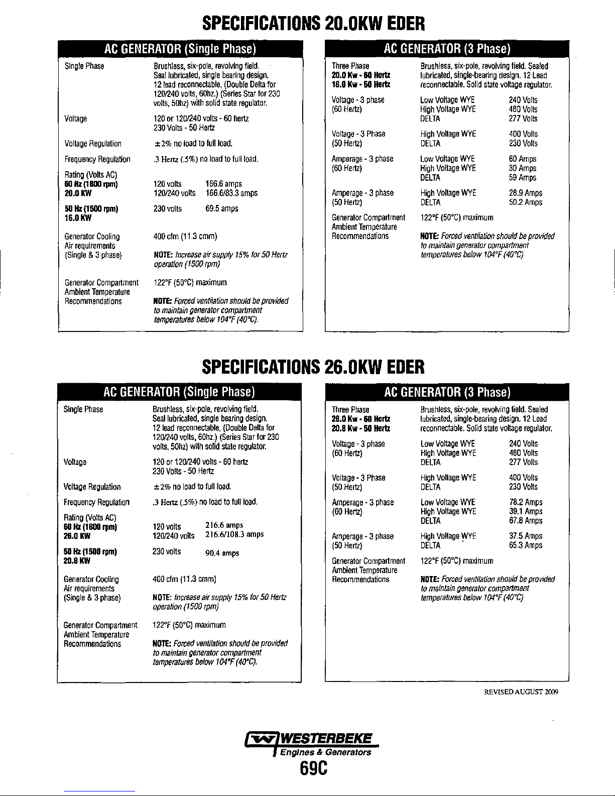
AC
GENERATOR
Single
Phase
Vollage
Vollage
Regulation
Frequency
Rating
60
2O.0KW
50
16.0KW
Generator
Air
(Single
Generator
Ambient
Recommendations
Regulation
(Volts
Hz
Hz
AC)
(18011
rpm)
(1500
rpm)
Cooling
requirements
& 3
phase)
Compartment
Temperature
(Single
Brushless.
Seal
12
1201240
volts,
120
230
±
.3
120
1201240
230
400
NOTE:
operation
122°F
NOTE:
to
temperatures
six·pole.
lubricated.
lead
reconneclable.
volts.
50hz)
with
or
1201240
Volts -50
2%
no
load
Henz
(.5%)
volts
volts
volts
cfm
(11.3
Increase
(1500
(50°C)
Forced
maintain
generator
SPECIFICATIONS
20.0KW
Phase)
revolving
single
bearing
(Double
60hz.)
(Series
solid
slate
volts -60
Hertz
to
full
load.
no
load
to
166.6
amps
166.6/83.3
69.5
amps
cmm)
air
supply
rpm)
maximum
ventilation
compattment
below
104°F
field.
design.
Slar
regulator.
hertz
full
load.
amps
15%
should
(40°C).
Della
for
for
50
be
provided
for
230
Hertz
Three
20.0
16.0
Vollage
(60
Vollage
(50
Amperage
(60
Amperage
(50
Generator
Ambient
Recommendations
Phase
Kw -60
Kw -50
-3
phase
Hertz)
-3
Phase
Hertz)
-3
Hertz)
-3
Hertz)
Compartment
Temperature
EDER
AC
GENERATOR
Hertz
Hertz
phase
phase
Brushless,
lubricated,
reconnectable.
Low
High
DELTA
High
DELTA
Low
High
DELTA
High
DELTA
122°F
NOTE:
fa
temperatures
six-pole,
single-bearing
Vollage
Vollage
Voltage
Vollage
Vollage
Vollage
(50°C)
Forced
maintain
(3
Phase)
revolving
Solid
state
WYE
WYE
WYE
WYE
WYE
WYE
maximum
ventilation
generator
below
compartment
104°F
field.
design.
voltage
240
480
277
400
230
60
30
59
28.9
50.2
should
(40°C)
Sealed
12
Lead
regulator.
Volts
Volts
Volts
Volts
Volts
Amps
Amps
Amps
Amps
Amps
be
provided
AC
GENERATOR
Single
Phase
Voltage
Vollage
Regulation
Frequency
Rating
60
26_0
50
2O.8KW
Generator
Air
(Single
Generator
Ambient
Recommendations
Regulation
(Volts
Hz
Hz
requirements
AC)
(18011
rpm)
KW
(1500
rpm)
Cooling
& 3
phase)
Compartment
Temperature
(Single
Brushless,
Seal
12
1201240
volts,
120
230
±
.3
120
1201240
230
400cfm
NOTE:
operation
12n
NOTE:
to
temperatures
six-pole,
lubricated,
lead
reconneclable,
volts,
50hz)
with
or
1201240
Volts -50
2%
no
load
Hertz
(.5%)
volts
volts
volts
(11.3
Increase
(1500
(50°C)
Forced
maintain
generator
SPECIFICATIONS
26.0KW
Phase)
revolving
single
bearing
(Double
60hz.)
(Series
solid
slate
volts -60
Hertz
to
tuilioad.
no
load
to
2t6.6
216.6/108.3
90.4
amps
cmm)
air
supply
rpm)
maximum
ventilation
compartment
below
104°F
regulator.
hertz
full
amps
15%
should
(40°C).
field.
design.
Della
Slar
for
load.
amps
for
50
be
for
230
Hertz
provided
Three
26.0
20.8
Vollage
(60
Vollage
(50
Amperage
(60
Amperage
(50
Generator
Ambient
Recommendations
Phase
Kw -60
Kw -50
-3
phase
Hertz)
-3
Phase
Hertz)
-3
Hertz)
-3
Hertz)
Compartment
Temperature
EDER
AC
GENERATOR
Brushless,
Hertz
Hertz
phase
phase
lubricated,
reconnectable.
Low
High
DELTA
High
DELTA
Low
High
DELTA
High
DELTA
122'F
NOTE:
temperatures
Vollage
Vollage
Voltage
Vollage
Vollage
Voltage
(50°C)
to
maintain
(3
six-pole,
single-bearing
Solid
WYE
WYE
WYE
WYE
WYE
WYE
.
maximum
Forced
ventilation
generator
below
Phase)
revolving
field.
design.
slate
vollage
240
480
277
400
230
78.2
39.1
67.8
37.5
65.3
should
compartment
104°F
(40°C)
Sealed
12
Lead
regulator.
Volts
Volts
Volts
Volts
Vans
Amps
Amps
Amps
Amps
Amps
be
provided
REVISED AUGUST 2(09
Engines & Generators
69C
Page 82

NOTE
·For "*" marked screws,
tightening.
The letter
the
two
"M"
nominal
threads.
in
Size x Pitch means that
outside
diameter
bolts
TORQUE
and
nuts
on the table,
the
in mm
of
the threads. The
SPECIFICATIONS
screw,
apply
bolt
or
pitch
nut
engine
dimension
is
oil
the
to
their
stands
nominal
threads and seats
for
metric.
distance
in
The
mm
between
before
size
is
Item Size x
Cylinder head cover screw
'Cylinder head screw
'Connecting rod screw
'Flywheel screw
'Crankshaft screw
bearing case screw
'Main
Rocker arm
Nozzle holdor assembly
Nozzle holder
Injection pipe retaining nut
Overflow pipe assembly retaining nut
Oil switch taper screw
Oil cooler joint screw - 39.2
Oil pump cover screw - 7.9 to 9.3 0.80
Glow plugs
br
dcket screw
Pitch
-
M12x
M10 x 1.25
M12 x 1.25
M10x1.25
1.25
M16x1.5
M14x1.5
M20 x 1.5
-
M12 x 1.5
M12x1.5
1/8
R
M10
x 1.25
N·m
6.9 to 11.3 0.7
98.1
to 107.9 10.0
78.5 to 83.4
98.1
to 107.8 10.0
255.0 to 274.6
137.3to
49.0 to 55.9 5.0
49.0 to 68.6
34.3 to 39.2 3.5 to 4.0
22.6 to 36.3
19.6 to 24.5 2.0
14.7 to 19.6 1.5 to 2.0 10.8
19.6 to 24.5
147:1 14.0 to 15.0
..
to
44.1 4.0 to 4.5 28.9 to 32.5
8.0
26.0
5.0 to
2.3
2.0
kgf·m
to
1.15
to
11.0
to 8.5
to
11.0
to
28.0
to
5.7
7.0
to
3.7
to
2.5 14.5
to
0.95 5.8 to 6.9
to
2.5 14.5
72.3 to 79.6
57.9
72.3 to 79.6
188.1
101.3 to 108.5
36.2
36.2
25.3
16.6 to 26.8
5.1
ft-Ibs
to
8.32
to
61.5
to
202.5
to
41.2
to
50.6
to
28.9
to
18.1
to
14.5
to
18.1
Starter's terminal B mounting nut
Injection pump gear mounting nut
Injection pump unit mounting nut
Gear case cover
Relief valve
Idle gear mounting screw
Plate
mounting screw
Camshaft set screw
Flywheel
Crankcase 2 mounting screw
Injection pump mounting screw
Injection pump mounting nut
Boost Actuator Governor weight mounting nut
Fuel camshaft stopper mounting screw
retaining screw
housing mounting screw
M8 x 1.25
M14x1.5
M8
M8 x 1.25
M8
M8 x 1.25
M8
M12 x 1.25
M10 x 1.25
M8
M8
M12 x 1.25
x 1.25
-
x 1.25
x 1.25
x 1.25
x 1.25
-
9.8
to
11.8 1.0 to 1.2 7.2
73.6 to 83.4
to
17.7
23.5 to 27.5 2.4 to 2.8 17.4
68.6 to 78.4 7.0 to 8.0 50.6
23.5
23.5
23.5
77.5
49.0
23.5 to 27.5 2.4 to 2.8 17.4
17.7 to 20.6
39.2
62.8
20.6 1.8 to
to
27.5 2.4 to 2.8 17.4 to 20.3
to
27.5 2.4
to
27.5
to
90.2 7.9
to
55.9 5.0 to 5.7
to
45.1
to
72.6
7.9
to
9.3 0.80
7.5 to 8.5 54.2
2.1
to
2.8 17.4
2.4 to 2.8 17.4
to
9.2
1.8t02.1
4.0
to
4.6
6.4 to 7.4 46.3
to
0.95 5.8
13.0t015.2
57.1
36.2
13.0
28.9
to
to
to
to
to
to
to
to
to
to
to
to
to
8.7
61.5
20.3
57.9
20.3
20.3
66.5
41.2
20.3
15.2
33.3
53.5
6.9
"""
WESTERBEKE
Engines & Generators
70
Page 83

TORQUE
SPECIFICATIONS
x Pitch
Item
Size
Governor housing mounting screw M6 x 1.0
Anti-rotation nut
Balancer shaft set screw
Bearing case cover mounting screw
M5 x 0.8
M8 x 1.25
M8 x 1.25
Alternator pulley nut -
When the tightening torques
!~e
Nominal
Diameter
M6
M8
M10
M12
Unit
are
N·m
7.9
to
9.3 0.80
t7.7
to
20.6
39.2 to
45.1
62.8 to 72.6
not specified, tighten the screws, bolts and nuts according to the table below.
Standard Screw
and
Bolt
@
kgf·m
to
0.95 5.8
t.8
to
2.t
4.0
to
4.6 28.9
to
7.4 46.3 to 53.5
6.4
It·lbs
13.0
to
Screw and bolt material grades are shown by numbers punched
be sure
to
check out the numbers as shown below.
Punched
None
number
or
4
7
Screw
Standard
Sp.;cial screw and bolt S43C, S48C (Refined)
and
screw
bolt
and
material
bolt
8841 , S20C
grade
N·m
9.8 to 11.3
2.8 to 4.0
23.5 to 27.5
23.5
to
58.3 to 78.9
to
6.9
to
15.2 23.5
33.3
on
the screw and bolt heads. Prior
kgf·m
1.0t01.15
0.29 to
to
2.4
27.5
2.4 to 2.8
5.95 to 8.05 43.0
Special Screw and Bolt
N·m kgf·m
9.8
to
t t.3
to
27.5
48.11055.9 4.9
77.5
to
90.2 7.9
t.OO
2.4
0.41
2.8
(j)
to
1.15 7,23
to
2.8 17.4
to
5.7 35.4
to
9.2
ft-lbs
7.23 to 8.32
2.1
to
3.0
17.4
to
20.3
17.4 to 20.3
to
58.2
It·lbs
to
8.32
to
20.3
to
41.2
57.1
to
66.5
to
tightening,
Engines
71
& Generators
Page 84

(1)
,
~
I?,§
((==-:J)
A=
SPECIAL
Diesel Engine Compression Tester
Code
TOOLS
No
~~('~
(3)
(4) (5) (6) (7) (8)
(9)
t~t~t\@'
_ .
=tJ
~(2)
"
Ii
~
~
:;
(4)
~ ~
® <!)
(5)
(6)
Application: Use to measure diesel engine compression and
(1
)
Gauge
(2) L
Joint
Adaptor A (9)
(3)
(4)
Adaptor B
(5)
Adaptor C
(6) Adaptor E
Oil Pressure Tester
Code No :
Application:
(1) Gauge
(2) Cable
(3) Threaded Joint
(4) Adaptor 1
: 07909-30208 (Assembly)
07909-30934
07909-31211
07909-31231
diagnostics of need for major
07916-32032
Use to measure lubricating oil pressure.
(A
to
F)
(E
and
(H)
(7) Adaptor F
(8) Adaptor G
(10) Adaptor t
(11
)
(5) Adaptor 2
(6)
(7)
(8)
07909-31251 (G)
07909-31271
F)
07909-31281 (J)
overhaul.
Adaptor H
Adaptor J
Adaptor 3
Adaptor 4
Adaptor 5
(I)
~j~~
(1) (2) (3) (7) (8)
Plastigaae
Code No : 07909-30241
Application: Use to check the oil clearance between
..
rod
alignment.
1.0.
11.81
in.)
on
cylinder head, cylinder
Measl.ring :
range
Connecting Rod
Code
No:
Application:
Applicable:
range 30 to
Red Check
Code No :
Application:
crankshaft and bearing, etc
Green ..... 0.025 to 0.076 mm (0.001
Red .........
Blue ......... 0.102 to 0.229 mm (0.004
Alignment Tool
07909-31661
Use to check the connecting
Connecting rod big end
Connecting rod
65
07909-31371
Use to check cracks
block,
0.051 to 0.152 mm (0.002
75
mm (1.18 to 2.95 in.) dia.
length
to
300 mm (2.56
etc
..
to
to
0.003 in.)
to
0.006 in.)
to
0.009 in.)
...v:
WESTERBEKE
Engines & Generators
72
Page 85

c
I--'
E
The
G
f-'!..
A
SPECIAL
TOOLS
following special tools are not provided, so make them referring to the figure.
Engine
Stand
D
F
~.
~
If
:/
1B
J
.---III:IP
K
Application
A
B
C
0
E
F
G
H
I
J
K
L
,
M
N
0 6
p
C10
:Use
to
support engine.
480
mm
(18.90 in.)
50 rnm (1.97 in.)
10B.S
mm
(4.272 in.)
263 mm (10.35 in.)
12.5
mm
(0.492 in.)
237.5
mm
(9.350 in.)
142.5
mm
(5.610 in.)
95 rnm (3.74 in.)
4.14
mm
dia. (o.S5 in. dia.)
40 rnm (1.57 in.)
210
mm
(8.27
in.)
190
mm
(7.48 in.)
100
mm
(3.94 in.)
6
mm
(0.24 in.)
mm
(0.24 In.)
25
mm
dia. (0.98 in. dia.)
Chamfer 10 mm (0.394 in.)
B
E
F
I
'¥
r
H I
Flywheel Stopper (for
Application:
A 140
A
C
o I
{l1-
{
J
B
C
0 49.3
E
F 23.8
G
H
I
J 8 mm (0.31 in.)
Tool
for
Application:
A
B
C
0
E
F
G
H
I
J
K
mm
aOmm(3.15in.)
49.3
mm
mm
23.8
mm
mm
11
mm
56.5
mm
56.5
mm
Aligning
Use
115
mm
56 mm (2.2047 in.)
17 mm (0.6693 in.)
20 mm (0.7874 in.)
14 mm dia. (0.5512 in. dla.)
11
mm
14
mm
17.5
mm
17.5
mm
35 mm (1.3780 in.)
19 mm (0.7480 in.)
SAE
Use
to
loosen
(5.5 in.)
(1.94 in.)
(1.94 in.)
(0.94 in.)
(0.94 in.)
dia. (0.43 in. dia.)
(2.22 in.)
(2.22 in.)
the
Crankcase 1
Flywheel
and
and
tighten the flywheel screw.
and
2
for aligning the crankcase 1
(4.5276 In.)
dia. (0.4331
dia. (0.5512 in. dia.)
(0.6890 in.)
(0.6890 in.)
In.
dia.)
Housing)
and
2
~
WESTERBEKE
Engines & Generators
73
Page 86

A
B
f,..
~
E
f---
L
-
(
IF
G
H
I J K
'-
h,
-
L
M
N
A
~
C
0
FI
c
1
7:1
C1
C 2
a b
SPECIAL
TOOLS
Gear Case Oil Seal Replacing Tool
Application: Use to press fit the oil seal.
A 148.8
mm
(5.8582
in.)
B
50
mm
(1.9685 in.)
C
18.8
mm
(0.7401 in.)
D
13.7 to 13.9
mm
(0.5394 to 0.5472 in.)
E
11
mm
(O.433 in.)
F
18
mm
dia. (0.7087 in. dia.)
G 38
rnm
dia. (1.4961 in. dia.)
H
45
rnm
dia. (1.7716
in.
dia.)
I 57.9
to
58.1
mm
dis. (2.2795 to 2.2874 in. dia.)
J
79.5
mm
dia. (3.1299 in. dia.)
K
87
mm
dia. (3.452 in. dia.)
L
12
mm
(0.4724 In.)
M
40
mm
(1.5748 In.)
N 120
mm
(4.7244
in.)
Small End Bushing Replacing Tool
Application:
Use to press out and to press fit the small end
bushing.
[Press oul)
A
157mm(6.1811
in.)
B
14.5
mm
(0.571
in.)
C
120
mm
(4.7244 in.)
D
30.0
mm
dis. (1.1811 in. dia.)
E
32.95
mm dia. (1.2972 in. dia.)
F
20
mm
dla. (0.7874 in. dia.)
a
6.3
Jim
(250 #In.)
b
6.3
tim
(250 pin.)
C1
Chamfer 1.0
mm
(0.039 in.)
C2
Chamfer
2.0
mm
(0.079 in.)
[Press
Iii)
A
157mm(6.1811
in.)
B
14.5
mm
(0.571 in.)
C
120 mm (4.7244 in.)
D
30.0
mm
dia. (1.1811 in. dia.)
E
42.000 mm dla. (1.6535 in. dia.)
F
20 mm dia. (0.7874 in. dia.)
a
6.3
pm
(250
pin.)
b
6.3
pm
(250 /lin.)
C1
Chamfer 1.0
mm
(0.039 in.)
C2
Chamfer
2.0
mm
(0.079 in.)
Engines & Generators
74
.
Page 87

e
".~]:
MIgl
~5
-L.
·0
~
C
1
ci
a b
R
~W
~
U
A
C
FI
Cl
C 2
SPECIAL
TOOLS
Injection Pumo Gear Puller
Application
:Use for remove the injection pump gear from
governor shaft.
A
10
rnm
dia. (0.39 in. dia.)
B
M16
x Pitch 1.5
C 19
mm
(0.75 in.)
0
0.5
mm
radius (0.02 in. radius)
E 0.89 rad (50 ")
F
10
mm
(O.39 in.)
G 20
mm
(0.79 in.)
H 5
mm
(0.20 In.)
I 95
mm
(3.74 in.)
J 125 rnm (4.93 in.)
K
5
mm
(0.20 in.)
L
M16
x Pitch 1.5
M 30
mm
(1.18in.)
N
9.5
mm
(0.3740 in.)
0
11
mm
(0.4331 in.)
p
9.5
mm
(0.3740 in.)
Q
15.5
mm
(0.6102 in.)
R
4.5
mm
radius
(0.1
B in. radius)
S 20
mm
(0.79
in.)
T
20
mm
(0.79
in.)
U
80
mm
(3.1496 In.)
W 12
rnm
(0.47
in.)
C2
Chamfer
2.0
mm
(0.079 in.)
Idle Gear Bushing Replacing Tool
Application:
Use to press out and to press fit the bushing.
1.
For idle gear bushing
A
196
mm
(7.7165 in.)
B
37.Smm
(1.476 In.)
C
150
mm
(5.9055 in.)
0 44.95
mm
dia.{1.7697 in. dia.)
E 48.100
to
48.075
mm
dia. (1.8937 to 1.8927
in.
dia.)
F
20
mm
dia. (0.7874
in.
dia.)
a
6.3
lim
(250 liin.)
b
6.3
Jim (250 Jiin.)
Cl
Chamfer
1.0
mm
(0.039 in.)
C2
Chamfer
2.0
mm
(0.079 in.)
Engines & Generators
75
Page 88

o
E
F
""
f2
Cl
C~
C
A
B
C
1
SPECIAL
TOOLS
Valve Guide Replacing Tool
Application: Use to press out and press fit the valve guide.
[Intake valve guide]
A 20
mm
dia. (0.79 in. dia.)
B 11.7 to 11.9
mm
dia. (0.460 to 0.468 in.dia.)
C 6.5 to 6.6
mm
dia. (0.256
to
0.259 in.dia.)
0 225
mm
(8.86 in.)
E
70 mm (2.76 in.)
F
45
mm (1.77 in.)
G
25
mm
(O.9B
in.)
H
5mm(O.197in.)
I
6.7
to
7.0
mm
dia. (0.263 to 0.275 in.dia.)
J
20
mm
dia. (0.787 in.dia.)
K 12.5
to
12.8
mm
dia. (0.492 to 0.504 in.dia.)
L
B.9
to
9.1
mm (0.350 to 0.358 in.)
Cl
Chamfer 1 .0
mm
(0.039 in.)
C2
Chamfer
2.0
mm
(O.079 in.)
CO.3
Chamfer 0.3
mm
(0.012 in.)
[Exhaust valve guide]
A 20
mm
dla. (0.79
in.
dia.)
B
12.96 to 12.98
mm
dia. (0.510 to 0.511 in.dia.)
C
7.50
to
7.70
mm
dia. (0.295 to 0.303 in.dia.)
0 225
mm
(8.66 in.)
E
80
mm (3.15 in.)
F 40
mm
(1.57 in.)
G
14.5 to 15.5
mm
(0.57 to 0.61 in.)
H 5
mm
(0.197 in.)
I 8.0 to
8.1
mm
dia. (0.31 to 0.32 in.dia.)
J
17.5 to 18.5
mm
dia. (0.689
to
0.728 in.dla.)
K
13.1 to
13.2
mm
dia. (0.516 to
0.520
in.dia.)
L 9.9 to 10.1
mm
(0.390 to 0.398 in.)
Cl
Chamfer
1.0
mm
(0.039 in.)
C2 Chamfer
2.0
mm
(0.079 in.)
CO.3
Chamfer 0.3
mm
(0.012 in.)
Balancer Bushing Replacing Tool 1 Assembly
Application: Use to press fit the bushing.
No.
name
of ParI Q'ly
(1)
Shaft
1
(2) Piece 1
1
(3).
Piece 2
1
Remarks
(4)
Boll
2
M6 x Pl.0
~
WESTERBEKE
EngInes & Generators
76
Page 89

SPECIAL
TOOLS
(1)
Malenai: 845C-D
(2) Permanent Magnet: ¢ a
rnm
(0.3150 in. dia.)
Thickness: 3 mm (0.1181 in.)
A
CO.2
C3
.p---'-'-----"'r-(,
BCD
A
co_~
FO:;
H
I J
Cl
E L
G
.~
~
----
L M
5
r-
r~
N
9
Jig for Governor Connecting Rod
Application :Use for connecting the governor connecting rod to
the rack pin of the fuel injection
pump
assembly.
A
A1
mm
(O.0394
in. radius) V
3
rnm
(0.1181 In.)
B
Chamfer 0.2
mm
(0.0079 in.) W
10
mm
(0.3937
in.)
C
Chamfer 2
mm
(O.OlB?
in.) X
a mm (0.3150 in.)
D
35
rnm
dia.{1.3780
in.
dia:)
E Chamfer 1
mm
(0.0394 in.)
F Chamfer
0.1
rom
(0.0039 in.)
G
R1
mm
(0.0394
in.
radius)
H Chamfer 0.2
rom
(0.0079 in.)
i
RS
mm
(0.3150
In.
radius)
J
Rl
mm
(0.0394 in. radius)
K
Rl
rom
(0.0394
in.
radius)
L Chamfer 0.2
rom
(0.0079 in.)
M Chamfer 0.2 mm (0.0079 in.)
N
29
mm(1.1417in.)
0
6 mm
{O.2362
in.j
p
10.7 mm
(O.4213
in.)
a
35
mm
(1.3780 in.)
---
R 99.3 mm (3.90'35 in.)
8
45.65
to
45.75 mm (1.7972
to
1.8012 in.)
T
145
mm
(5.7087 in.)
u 16.15
to
16.35
mm
dia. (0.6359 to 0.6439 in. dia.)
..
Auxlhary Socket for Fixing Crankshaft Sleeve
Application: Use to fix the crankshaft sleeve.
A
Rmax",
t2.5
S
B
94.5 to 95.0 mm (3.7205
to
3.7402 in.)
C
40 mm (1.5748 in.)
D
30mm
(1.1811 in.)
E 12 mm (0.4724 in.)
F
7.9 to
8.1
mm (O.3110
to
0.3189 in.)
G
20 mm (O.078? in.)
H
130mm(5.1181
in.)
i 99.410 99.6 mm (3.913410 3.9213 in.)
J 95.05 to 95.20 mm (3.7421
10
3.7480 in.)
K 3 mm dia. (0.1181 in.dla.)
L 15 mm (0.5905 in.)
M
10 mm (0.3937 in.)
N
90 mm (3.5433 in.)
0 115 mm (4.5275 in.)
p
16.910
17.1
mm (0.665410 0.6732 in.)
Cl
Chamfer 1.0 mm (0.039 in.)
C3
Chamfer 3.0 mm (0.1181 in.)
C5 Chamfer 5.0 mm (0.1969 in.)
CO.2
Chamfer 0.2 mm (0.0079 in.)
1--60.3
Chamfer 0.3 mm (0.0118 in.)
Engines & Generators
77
Page 90

la)
[b)
(3)
(2)
(1)
Ie)
(3)
~
..
_-
(1)
F
(3)
(2)
(1)
G
c
(4)
A-A
)@K(7)
(8)
(6)
(9)
(4)
(11)
(4)
A
B
A
o E
A
(5)
SPECIAL
TOOLS
Balancer Bushing Replacing Tools
3.
4.
5
Application:
Use to press fit the bushing.
No.
Name
of
Part
(1
)
(2)
(3)
(4)
(5)
(6)
(7)
(8)
(9)
(10)
(11)
(12)
[a] Tool 3
[b]
Tool4
Bracket
Flange
Nul
Washer
Shaft
Piece
1
Crevis
Washer
Cotter Pin
Joint
1
Piece 2
Joint
2
Piece
3
[e]
Tool5
A:
Section
Balancer Bushing Replacing Tool Components parts
1) Bracket
A
12 mm (0.47 in.)
8
50
mm
(1.97
in.)
C
Chamfer 1 mm
(0.04 in.)
0
60
mm
(3.15 in.)
E
104
mm
(4.09
in.)
F
22
mm
(0.87
in.)
G
13
mm
dia. (0.51 in. dia.)
2) Shaft
A
44
mm
dia.
(1.73
in. dia.)
B
12
mm
(0.47 in.)
C
Chamfer 1
mm
(0.04 In.)
0
3 mm (0.12 in.)
E
3 rnm (0.12 in.)
F
30
mm
(1.18in.)
G
38 mm (1.38 in.)
H
35
rnm (1.36 in.)
I
M12
x P1.25
J
53
mm
(2.09
in.l
K 4 mm (0.16 in.)
L 75
mm
(2.95 in.)
M
57
mm (2.24 in.)
~-
70 mm (2.76 in.)
0
19.5 rnm (O.77 in.)
p
12 mm (0.47 in.)
0
0.8
mm
(O.03
in.)
A
6 mm (0.24 in.)
~
WESTERBEKE
Engines & Generators
78
O"y
1
1
1
1
1
1
1
1
1
1
1
1
Page 91

SPECIAL
TOOLS
3)
Piece 1
A
26 mm (1.02 in.)
B
18 mm (0.71 in.)
C
16.5 to 17.0
mm
(0.6496 to 0.6693 in.)
0 1.5
mm
(0.06 in.)
E
54.0 to 54.2
mm
dia. (2.1260
to
2.1339
in.
dia.)
F
50.55 to 50.75
mm
dia. (1.9902 to 1.9980
in.
dia.)
G 16 mm (0.63 in.)
H
Chamfer 1
mm
(0.04 in.)
I
8.5 mm dia. (0.33 in. dia.)
J 0.4
mm
(D.OIS? in.)
K
3 mm (0.12 in.)
L
19
mm
(0.75 in.)
M
Chamfer
0.5
mm
(0.02 in.)
N 36
mm
(1.42 in.)
0
45
mm
dia. (1.77 in. dia.)
p
0.78 rad (45
')
Q
11.5
mm
(0.45 in.)
4)
Joint
1
E B A
B
-,
-\
~
;'
:fD~
-I-.
. -
-
1'-.
.-
.
!~
..A/
r,
G
I
c
B
A
M12 x Pl.2S
J 85
mm
(3.35 in.)
B Chamfer 1
mm
(0.04 In.) K 70 mm (2.76 in.)
C
30
mm
dia. (1.18 in. dla.)
L
178
mm
(7.01 in.)
0
13
mm
dia. (0.51 in. dia.)
E
Chamfer 3
mm
(0.12 in.)
H K
F
3mm(O.12in.)
J
G
45 mm (1.77 in.)
L
H 75
mm
(2.95
in.)
I 57
mm
(2.24 in.)
5)
Piece2
A
+
~J
~
~
-
Q
A 26
mm
(1.02 in.)
B
18
mm (0.'l1 in.)
C
16.5 to
17.0 mm (0.6496 to 0.6693 in.)
E
~l~
L
r'-J
F n.l
--
~
-1-
/M
Q-
0 1.5
mm
(0.06 in.)
E 53.5 to 53.7
mm
diet.
(2.1063 to
2.1142
in. dla.)
F
50.05 to 50.25 mm dia. (1.9705 to
1.9783
in. dia.)
G
16
mm (0.63 in.)
-1.
p
H Chamfer 1 mm (0.04 in.)
I 8.5
mm
dia. (0.33 in. dia.)
J 0.4
mm
(0.0157 in.)
K
3mm(0.12in.)
L 19 mm (0.75 in.) 0 45 mm dia. (1.77 in. dia.)
M Chamfer
0.5 mm (0.02 in.) P 0.78 rad
(45°)
N 36 mm (1.42 in.)
Q
11.5 mm (0.45 in.)
-..v:
WESTERBEKE
Engines & Generators
79
Page 92

SPECIAL
TOOLS
6)
Joint
2
EB
A
B
-,
\
I.
A
M12 x P1.25
8
Chamfer
1 mm (0.04 in.)
:tDI
+
.,.
~I-'Y
B
G
,
,
c
C
30
mm
dia. (1.18 in. dia.)
D
13
mm
dia. (0.51 in. dia.)
E
Chamfer 3 mm
(0.12 in.)
H
K
F
3
mm
(0.12 in.)
J
L
G 45
mm
(1.77 in.)
H 75
mm
(2.95 in.)
I 57
mm
(2.24 in.)
J 85
mm
(3.35 in.)
K 70
mm
(2.76 in.)
L 394
mm
(15.51 in.)
7) Piece 3
A 26
mm
(1.02 in.)
Q
8 18
mm
(O.7t in.)
C
16.5
to
17.0
mm
(0.649610 0.6693 in.)
D
1.5
mm
(0.06 in.)
--
N
Q_
E
53.0
to
53.2
mm
dia. (2.0866 to 2.0945 in. dia.)
F
49.55 to
49.75
mm dia. (1.9508
to
1.9587 in. dia.)
G 16
mm
(0.63 in.)
H
Chamfer 1 mm
(0.04 in.)
I 8.5
mm
dia. (0.33
in.
dia.)
J
0.4
mm
(0.0157 in.)
K
3
mm
(0.12
in.)
L
19
mm
(0.75 in.)
M
Chamfer
0.5
mm
(0.02 in.)
N
36
mm
(1.42
in.)
0
45
mm
dia. (1.77 in. dia.)
p
0.78
,ad
(45
')
Q
11.5
mm
(0.45 in.)
Engines & Genera/ors
80
Page 93

A
E
B F
J
C
D F
F~
Fl,u
/-
·G -tt-
K·
Lr?/P
Q~
(
17
M
'N
.t
R
N
V
W
x
y
A
B
D E
C
F
G
L
C
J
H
SPECIAL
TOOLS
V-s
I'.
Balancer Bushing Replacing Tool 1 Componenls Parts
1)
Shaft
A
498
mm
(19.61 in.)
B
318.810319.2
mm
(12.5726 to 12.5669 in.)
C 102.810103.2
mm
(4.047210 4.0630 in.)
0 60 mm (2.36 in.)
E 8
mm
(0.31
in.)
F
5
mm
(0.20 in.)
G
30
mm
dla.
(t.tS
in.
dia.)
H
65
mm
dia. (2.56 in. dia.)
I 6
mm
(0.24 in.)
J Chamfer 1
mm
(0.04 in.)
K
53
mm
dia. (2.09 in. dia.)
L 54.7 to 54.9 mm dia. (2.1535
1021614
in.
dia.)
M
0.26
rad.
(15
')
N
Chamfer
0.5
mm
(0.02
in.)
0
41
mm
dla. (1.61 in. die.)
p
32
mm
dla. (1.26 In. dia.)
Q
33.961 to 34.0
mm
die. (1.33/0 to 1.3386
in.
dia.)
A
18
mm
dia. (0.71 in. dla.)
S
19.96710
20.0
mm
dla. (0.7861 to 0.7874 In. die.)
U
3
mm
(0.12 in.)
V 149.1 to 149.4
mm
(5.8701 to 5.8819 in.)
W 365.1 to 365.4
mm
(14.3740 to 14.3858 in.)
X 123
mm
(4.84 In.)
y
375
mm
(14.76 in.)
Z
M6 x Pl.0
depth 7 mm
(0.28 in.)
a
Chamfer 2 mm
(0.08 in.)
2) Piece 1
A
Chamfer
0.1
mm
(0.004 in.)
B 1
mm
(0.04 in.)
C
Chamfer 1 mm
(0.04 in.)
0
53.81053.9
mm
dia. (2.118110 2.1220 in. dia.)
E
20.021020.041
mm
dia. (0.788210
0.7890
in. dia.)
F
48
mm
dia. (1.89 in. dia.)
G 49.934 to 49.94
mm
dia.
(1.9659101.9661
in. dia.)
H 8
mm
(0.31 in.)
I 2
mm
(0.08 in.)
J
35
mm
(1.38 in.)
K 5
mm
(0.20 in.)
L
0.26
rad (15
')
Engines & Generators
81
,
Page 94

o
E
/'
B
C,.
F
.-.-
'-
r!
~J
H
L
M
A
---AL
-K
J
}
A
G
E F G H
P
o
SPECIAL
3)
TOOLS
Piece 2
A
Chamfer
8 1 mm (0.04 in.)
C Chamfer 1
D
54.31054.4
E 34.025
F 48.5
50.421 to 50.44
G
H 8
I 2 mm
35
J
5 mm
K
0.26 rad (15
L
mm
mm
0.1
to
34.05
mm
dia.
(0.31 in.)
(O.OB
(1.38 in.)
(O.20
mm
mm
in.)
in.)
0)
rnm
(O.004
(0.04 in.)
dia. (2.137810 2.1417
mm
dia. (1.3396 to 1.3406 in. dia.)
(1.9094
in.
mm
dia. (1.9851 to 1.9858 in. dia.)
Balancer Bushing Replacing Tool 2
Application: Use to press fit the bushing.
35
A
8
C Chamfer 0.5
D
E Chamfer 1
F 40 mm dia. (1.57 in. dia.)
G
H
I
J
K 6
L
M
N
0
p
mm (1.38 in.)
33
mm (1.30 In.)
mm
1 mm
(O.04
in.)
mm
50.921
to 50.94
54.8 to 54.9
30
mm
49
mm
mm
125
160 mm (6.30 in.)
3 mm (0.12 in.)
5 mm (0.20 in.)
0.26 rad (15°)
mm
dia. (1.18 in. dia.)
dia. (1.93
(0.24 in.)
mm
(4.92 in.)
(0.02 in.)
(0.04
In.)
mm
dia. (2.0048 to
dia. (2.1575 to 2.1614 in. dia.)
In.
dia.)
in.)
dia.)
in.
2.0055
dia.)
in. dia.)
Engines & Generators
82
Page 95

GENERATOR
USE
OF
ELECTRIC
The power required
more than is required to keep it running after it is started.
Some
motors
require
others. Split-phase (AC) motors require more current to start,
under
similar
monly used on easy-starting loads, such as washing
machines, or where loads are applied after the motor is
started, such as small power tools. Because they require 5 to
7 times as much current to start
avoided, whenever possible,
ven
by a small
motors
to
run. The current required to start any motor varies with the
load
connected
compressor, for example, will require more current than a
motor to which no load is connected.
In
general, the cunent required
to medium starting loads will be approximately as follows:
MOTOR
"NOTE:
more
for
for
Ihis
made
jn
Because the heavy surge
motors
be damaged
seconds.
off all other electrical loads and,
on the electric motor.
Required
Run the genera)or first with no load applied, then at half the
generator's capacity, and finally loaded
indicted on the generator's data plate. The output voltage
should be checked periodically to ensure proper operation
the generating plant and the appliances it supplies.
voltmeter or ampmeter is not installed to monitor voltage and
load, check it with a portable meter and amp probe.
circumstances,
require
SIZE
(HPJ
1/6
114
113
112
314
1
In
Ihe
some
js
Ihallhe
larger
is
required
if
If
difficulty is experienced in starting motors, turn
Operating
MOTORS
to
start an electric motor
much
more
than
if
generator.
Capacitor
from 2 to 4 times
to
it.
An
electric
to
AMPS
RUNNING
(AMPERES)
3.2
4.6
5.2
7.2
10.2
13
above
lable
Ihe
small
molors
Ihan
hardesl
slaning
current
other
as
to run, their use should be
the electric motor is
and
as
much
motor
start
115-
FOR
maximum
for
larger
types
is
considerably
to
start
them
than
types.
They
are
to
be dri-
repulsion-induction
current
connected
\bIt
Amps for Starting is
(Splil-phase)
to
start
to
an
motors connected
AMPS
FOR
(~TARTIN~)
AMPERES
6.4
to
22.4'
9.2
to
32.2'
10.4
to
72.8'
14.4
to
29.2'
20.4
to
40.8'
26
to
52
ones.
The
reason
are
sizes.
of
current needed for starting
for
only
an
instant,
it can bring the motor up to speed in a few
the
generator
if
possible, reduce the load
will
Speed
to
its full capacity
If
an AC
com-
as
air
nol
not
as
of
INFORMATION
Generator
Frequency
cated by the following:
o When the generator
output frequency is
Therefore, to change the generator's frequency/voltage, the
generator's drive engine's speed must be changed using the
dips witch on the
generator
sensing PC board changed.
Generator
o Maintaining reasonable cleanliness is important.
Connections
corroded, and insulation surfaces
salts, dust, engine
build up. Clogged ventilation openings may cause excessive heating and reduced life
o For unusually severe conditions, thin rust-inhibiting petro-
leum-base coatings, should be sprayed
surfaces to reduce rusting and corrosion. Typical materials
suggested are Daubert Chemical Co.
and Ashland "Tectyle 506"
o
The
checked periodically
and for any evidence
should not be allowed
accelerate cracking. The bolts which fasten the drive disc
to the generator shaft must be hardened steel
8, identified by 6 radial marks, one at each
ners
o The rear armature bearing is lubricated and sealed;
maintenance
noisy
o Examine bearing at periodic intervals.
of
shaft should be detected when force is applied.
motion
shaft
Repair must be made quickly or major components
rub
,-----
WESTERBEKE recommends mounting a carbon
monoxide detector in the vesssel's Jiving quarters.
Monoxide, even in
The presence of carbon monoxide indicates an exhaust leak
from the engine
exhaust hose,
entering your boat.
If
air and correct the problem immediately!
Frequency
is
a direct result
ECU. The
changed
Adjustment
of
engine/generator speed,
is
run at 1800 RPM, the AC voltage
60 Hertz.
AC
output configuration
and
the
connections
on
the
of
voltage
Maintenance
of
terminal boards and rectifiers may become
may
start conducting
exhaus~
drive discs on single bearing generators should be
of
the head.
is
required.
or
rough-sounding, have it replaced.
is
detectable,
of
bearing socket outside bearing has occurred.
and
cause
major
Carbon
or
generator or from the exhaust elbow/
or
that
carbon monoxide is present, ventilate the area with clean
carbon, etc. are allowed
of
windings.
or
brushed over all
"Non-Rust AC-4!o"
or
equivalent.
if
possible for tightness
of
incipient cracking failure. Discs
to
become rusty because rust may
However,
bearings
damage
Monoxide
small
amounts,
fumes
if
the
are
wearing
to
generator.
Detector
is deadly.
from a nearby
of
SAE
of
the 6 cor-
bearing
No
side movement
or
wear
-----,
vessel
screws
grade
becomes
if
are
as
indi-
the
if
to
no
side
on
wiJI
Carbon
Eng/nes & Generators
83
Page 96

(SERIES
WYE)
SERIES
STAR
TWELVE
L
2
3
LEAD
N
WINDING/TERMINAL
AND
(NOMINAL)
(PARALLEL
PARALLEL
STAR
WYE)
VOLTAGES
BOARD
N
CONNECTIONS
L
12 1
10
11
'v
SERIES
DELTA
L9
10':11 2-3
0 0 0
;
5 9
)
,
Ll
50
50
60
60
l2
Hz
Hz
Hz
Hz
6
L2
L-L 400 volts
L-N 230 volts
L-L480
L-N 277 volts
Ll
PARALLEL
DELTA
L
10-12 2-4 6-8
1 3 5 7 9 11
6-7
0
L3
L
L3
volts
5
L
5
~12
N
L
o
11
L
9
10-12
1-3
0
2-4
5-7
(
,
Ll
L
10-12
1
N
L2
50 Hz L-L 200 volts
50
Hz
L-N
60 Hz L-L 240 volts
60
Hz
L-N 138 volts
2-4
,
3 9-11
5C 7
1.1
l2
6-8
9¢11
1
L3
liS
N
N
volts
6-8
~
0
L
0
3 L
91'
-:8:--N-7-'~
L
10-11
o
1-12
)
Ll
50
50
60
60
(Refer to Note
THREE
PHASE
ZIG-ZAG
lOt
L •
8-10
0 0
~
II
I
L2
Hz
L-L 230 volts
Hz
t-N
Hz
L-L
Hz
L-N 138 volts
L~
~2
'11
~L
2-12
5
9
I
,
L2
6-7
o
9-8
)
L3
115 volts
277
volts
#
1)
N
4 6 5
4-6
0
9
(
L3
L
o
3-7-11
i
,
N
50
Hz
60
Hz
DOUBLE
DELTA
7
L
4
8-11
o 0
1
10
50
Hz
50
Hz
60
Hz
60
Hz
L-L 115 volts
L-L 138 volts
2-3
5 12
N
1-L
1-N 115 volls
L-1.
L-N
6-9
7 4
t
Ll
230 volts
240 volts
120volts
10
1 L
o
50
Hz
50
HzL-N
60
Hz
60
Hz
(Refer to Note #1)
Note
#1
TI,e
nomillal vallie.
Nole
The
0.866.
Single
phase
current
#2
1711-ee
rated
power
Engines & Generators
L-L 230 volts
ll5
volts
L-L 277 volts
L-N 138 volts
phase
ampemge
must
110/
phase zig-zag cOl/nection.
must
be
load.
exceed
nwZlip/ied
the
by
84
50
50
60 Hz
60
(Refer
DOUBLE
DELTA
2-WlRE
7
L
8-11
0
C
1
10
N
Hz
L-L
Hz
L-N
L-L4IS
Hz
L-N 240 volts
to
4
2-3
~
5
50
Hz
L-N
60
Hz
L-N
346
200 volts
Note #2)
6-9
0
0
7 4
12
II
230
240
volts
volts
10
N
0
volts
vollS
Page 97

ELECTRONIC
ADJUSTABLE
OVERLOAD
THRESHOLD
PROTECTION
REGULATION
SR7-2G
AVR
AMP
FUSE
ADJUSTABLE
OF
UNDERSPEED
PROTECTION
THRESHOLD
INTERVENTION
""Hertz--,'jo~(-\-):E°O
DESCRIPTION
The
voltage regulator
performance.
circuitry protection to guard against operating conditions
could
be detrimental
information details
connections.
qualified technician.
TERMINAL
#1.
Excitation
#2.
Exciter
between S and
#3.
Exciter
#3A.
Supply voltage
#4.
Sensing voltage.
#5.
Supply voltage
#6.
Jumper
#7.
Not
#5B.
Npt
#5C. Sensing
POSSIBLE
Exciter Field: The exciter
connected
dark
blue
yellow)
Supply: There
1.
The supply coincides
SR712
(in case of three-phase generators,
connected
be
is
also sensing. This connection
generator
the
2.
The supply
generator equipped
supply.
of the
TIlis
These
CONNECTIONS
field
field
to
used.
used.
voltage.
CONNECTIONS
to
terminal 1 of the electronic regulator
or
black), while
should be connected
supply should
Witll
connected
does
regulator.
Supply
regulator.
(AVR)
ensures
advanced
to
the
procedures should
field
jumper
3A
DC positive.
SA
for
are
two
the star point). Ternnnals 3
to
each otller
1I0t
and
sensing separate. Tins
is
always connected
design
AVR
the
AC
generator.
voltage regulators adjustments
DC negative.
to
3 if
the
is
less
than
to
regulator (Ae).
to
regulator (Ae).
60
Hz
operation.
field
negative should
the
positive (nonnally
to
terminal
possibilities.
with
the
sensing.
be
connected
in
such a way
in
have auxiliary
with
auxiliary winding
optimum
is
equipped
The following
be
performed
regulator
160
VAC.
3.
In
tllis
to
tenninals 3
terminal S is
that
necessary
winding
is
the
to
terminals 3 and
AC
generator
with
and
by
AC
supply
be
(normally
red
or
case
the
and
normally
and 4 should
the
supply
when
the
for supplying
case of a
for
regulator
a
..
o
tllat
S
5
DO
1;!a1--tCDI~NEICT
rn---l
REMOVE
EXCITER
o
In
both
of
these
cases,
tlle
SR7/2
supply
270
VAC.
But
it
should be
should be bridged for supply
160
VAC,
while
the
voltage
Sensing: Sensing should
and
phase
alternator
Operation
and
low
FUNCTIONS
Volt:
voltage generated
the
screw
Stab:
If
time
turned
voltage
In
using
1.
2.
is
between
can
vary
only
and
phase.
at
6 should
frequency protection correctly regulated.
A
WARNING:
present.
against
screw
turned
order
The generator
and the potentiometer must be at
(turned
Slightly
filament
potentiometer
stabilizes.
Take
electrical
Witll
this potentiometer, it
is
is
turned
This
potentiometer optinlizes altemator
clockwise,
decreases but
cOllnterclockwise,
tends
to
adjust
the
following
fully
tum
160
from
80
therefore
60
Hz:
be
connected
all
OF
THE
by
tumed clockwise,
counterclockwise it
the
to
be
more
tlIis
must
counterclockwise).
clockwise
lamp
oscillates,
slowly
noted
that terminals 2
with
same
terminals
and
270
VAC.
be
connected
to
350
VAC.
is
normally
When
operating
to
each
Be
aware
that
necessary
hazards.
precautionms
REGULATOR
is
the alternator
the
the
stability
voltage
potentiometer
metllod.
be
counterclockwise
tends
the
response
stable.
working,
until
at
this
decreases
tlle
FOR
60Hz
FOR
50Hz
FIELD
can
vary
from
80
and
3
voltage
high
should
to
The
sensing
connected
at
60
other
in
voltages
between
be
terminals 4 and
order
left
Hz,
to
80
and
open
is
single
to
one
terminals
to
keep
may
be
safe
guard
if
POTENTIOMETERS
possible
in a very
voltage
starting
light
point,
to
increases,
decreases.
and
to
be
less
time
increases
cOlTectly,
frolll
maximum
generated
tUIll
until
adjust
the
simple
way.
if
performance.
the
response
stable.
If
and
we
advise
zero
load
stability
by
tlle
tlle
tlle
light
If
tlle
to
the
S
SA
tlle
the
Engines & Generators
85
Page 98

ELECTRONIC
Hertz:
With
this
potentiometer,
pre-calibrated
to
adjust
recalibrate this protection. you must take the generator
nonnal zero load condition, tum the potentiometer
clockwise
the
nominal
counterclockwise
decreased
When
the
value,
the
generator overheating.
protection
possible
Amp:
With
intervention level of
system
overload, necessary
applications.
To
modify
by
15%
minimum (counterclockwise)
During this period
condition
the
generator voltage value
At
this
voltage increases
Fuse: The electronic regulator
protects
malfunction. The
replaoed
then
sealed
the
low
frequency
until
the
limit
speed
by
10
and
measure
by 5 volts.
speed
decreases
voltage
to
has
of
and
point,
the
easily.
also
decreases proportionally,
Even
at
10%
of
the
calibrate the threshold
this
potentiometer,
the
an
intervention
when
this
protection,
the
normal
while
while
alternator
load,
of
time
turning
the
initial overload
to
the
from
fuse
(250V-5A,
overload protection. This protection
nominal
INTERNAL
12
WIRE
which
is
normally
by
the
manufacturer,
protection intervention.
position
%.
nominal
is
reached,
Then
turn
the potentiometer
the
voltage
by
more
than
if
we
advise
value,
at
other
it
is
possible
delay,
which
starting
you
the
motors
must
overload the generator
turn
the
potentiometer
and
wait about
voltage
the
at
10%
overheating in
value
potentiometer clockwise,
less
than
is
value.
is
equipped
quick acting, F
WIRING
it
then
value
10%
of
calibrating
it
is
obviously
values.
to
adjust
permits a
or
similar
twenty
decreases.
the
being
removed,
with a fuse,
cases
DIAGRAM
RECDNNECTABLE
is
possible
To
decrease
until
the
blocking
temporary
to
nominal
of regulator
type)
REGULATION
to
a
it
has
nominal
this
the
SR7-2G
TO
CONNECTIONS
REFER
TO
WIRING
IN
DIAGRAM
THIS
MANUAL.
I
I
seconds.
In
this
fix
one.
the
which
can
be
1f-
....
--
t
~"""'-----,
AC
SENSE
THE
COMPLETE
#52951
AVR
0
CJ
I
I
0
II.
SlU
".
TO
PANEL
FUSE
AVR
,
,
'
.,
"
•
"
"p;!lm!
:
-:
•
" '
: _
..
::..
..
I'
Itl
...
'"'-
, ,
G·
c3-
T(Rl(IHAl
,
r"-"
•
eli
~
I
:
I
I
~I
'-
..
aLOCK
SMOWH
fOR
n
,
7
5
:
CO~N(CTIONS
AR(
COHrlGUR[O
lO·'H
t~OHoa
_-.oc,
~
0
I~T~~--'
1_5~
VAt
,
.
,
0
..
I ,
- ,
,
12
4
,
~~i
~
EXCITER
l
TEL-
.~
-;:--:
.
-;
I
¥
I
..
ROTOR
I 1 " r i
I
I I r
I
EXCITER
I A I I
: I : B
I
I
I i I I
I - I I
I L I
L
-
.~mp
,IL..'
~~'"
:,':1111
r-~-
I I 1
-rl"
ill
-.!
_________
,'(6)
---r-----
ROTOR
-i>/-J.
DIODE
'--
_T
~
-----...1
~
~
IlIlllllWUIJ
III
III
o
In\c::=J
D
VOLTAGE
0 F
1=
p
I~
hO
~
W::::
RmULATOR
~~------;;,,,m--J--lJ
~=~======i==,,,=--
'WE
YEllOW
r-+
I'
J!
I I I
L-
-
_
8
"I
6
r
,---
i '
r
I
r
I.
,
"",",WESTERBEKE
'--
·f-
,
Engines & Generators
__
-'--===T-------.J
NOTE:
EXCITER
NO
LOAO
FULllOAU
9
COMPONENT
RESISTANCE
VALUES
(AT
STATOR
(each
wlndlng)
AUXIlIARY.
EXCITER
EXCITER
(each
pair)
ROTOR
__
DC
VOLTAGE I AUXILIARY
7.0
VUC
14.0
VUC
IN
OHMS
86'F)
___
0.041
____
STATOR_ll.3
ROTOR
_
VOLTAGE
215
VAC
222
VAC
0.9
__ . O.
2.7
72
86
Page 99

GENERATOR
SERVICING
TESTING
Test the speed sensor connector for voltage and resistance
values.
If
the values are correct, remove and inspect the magnetic
pick up. With the wires disconnected, unscrew the
magnetic pick
inspect the contact end.
the unit.
NOTE:
provided with the new magnetic pick
SPEED
Voltage
1.5 -2.5
Resistance
WIRES
THE
MAGNETIC
up
from the generator housing and visually
Carefully/allow the installation instructions
SENSOR
(whIle
VAC
TEST
cranking)
(al
rest)
VALUES
950
PICK
UP
COIL
If
any damage
-1000
ohm
~MIPU-I~AGINE1'ICPICK-UP
is
detected, replace
up
coil.
MAGNETIC
The MPU is installed
of
the flywheel bellhousing. This positions the MPU over
the teeth of the flywheel ring gear.
Viewing through this opening, manually rotate the engine
crankshaft so as to position the flat
gear's teeth directly under the opening. Thread the
into the opening until
tooth (Thread is 3/8" x 24). Back the
opening one tum and then lock it
jam
the
approximately 0.030 inches away from the flats of the
ring gear teeth.
To
en~ure
the crankshaft by
physical contact between the MPU and the ring gear teeth.
If
contact
MPU may be damaged. Remove the MPU and inspect
the
it.
Replace
installation procedure.
'
. signal to the controller.
NOTE:
MUST
existing wiring cable. Doing so will cause a erratic
PICK·UP
nut. This will position the end
the MPU is positioned correctly, slowly rotate
360" by hand to assure there is no
is
felt between the MPU and the flywheel teeth,
if
necessary and repeat the above
When replacing the Magnetic Pick-Up (MPU) it
be
replaced without cutting
[MPU]
in
it
INSTALLATION
the threaded opening
of
one of tlle ring
gently contacts the
MPU
in
this position with
and
on
the side
MPU
flat
of this
out of the
of
the MPU
splicing into the
AC
a
~
0.03010
"""
WESTERBEKE
Engines & Generators
87
Page 100

GENERATOR
NOTE:
AC
GENERATOR TROUBLESHOOTING
BE
PERFORMED WITH THE ENGINE OPERATING
TROUBLESHOOTING
MUST
AT
60
HZ.
NO
AC
VOLTAGE
RESIDUAL
NO
LOW
NO
HIGH
150
UNSTABLE
(ENGINE
LOAD
AC
VOLTAGE
LOAD
AC
VAC
OR
SPEED
VOLTAGE
15 • 20
60 • 100
OUTPUT
VOLTAGE
FAULT
OUTPUT
PRODUCED
VOLTS
OUTPUT
VAC.
VOLTAGE
HIGHER.
OUTPUT.
STEADY)
AT
AC.
NO
AT
LOAD.
AT
1.
Short
main
2.
Shorted
on
exciter
3.
Four
or
open
1.
Blown 6 AMP
auxiliary
2.
Faulty
1.
Reset
2.
Open
exciter
3.
Open
exciter
1.
Reset
2.
Faulty
1.
STB
pod
needs
PROBABLE
or
open
in
the
stator
winding.
suppressor
rotor.
more
shorted
or
diodes
on
exciter
fuse
circuit
feed
to
voltage
regulator
voltage
potentiometer.
or
shorted
rotor 1 to 3 diodes.
or
short
rotor
voltage
voltage
adjustment.
diodes
in
one
windings.
potentiometer.
regulator.
on
regulator
of
rotor.
AVA.
in.
the
three
CAUSE
4.
Open
stator
5.
Open
field
6.
Shorted
on
3.
Shorted
stator
4.
Faulty
5.
Short
6.
Short
2.
Faulty
in
exciter
winding.
in
rotating
winding.
condenser
exciter
or
auxiliary
voltage
in
rotating
in
the
voltage
rotor.
open
winding.
regulator.
exciter
regulator.
main
field
stator.
winding.
AC
VOLTAGE
60
·100
DROP
VOLTS
UNDER
AC.
LOAD
1.
Diode(s)
breaking
applied
on
exciter
down
when
(inductive)
rotor
load
1·3
is
diodes.
Engines & Generators
88
 Loading...