

Page 1

OPERATOR'S MANUAL
WESTERBEKE 12B TWO
MARINE DIESEL
ENGINE
Publication # 37185
Edition
One
January 1988
....v- WESJ'ERBEKE
WESTERBEKE CORPORATION
AVON
INDUSTRIAL PARK, AVON, MA
02322.
TEL:
(617)
588-7700
Page 2

SAFETY PRECAUTIONS
The
following symbols appear in this manual to call attention
to and emphasize conditions potentially dangerous to the
operator.
IWARNING\
The
above symbol is used in the manual to warn of possible
serious personal injury or loss of life.
CAUTION
The
above symbol is used
in
the manual to caution personnel
of possible
damage
to equipment
Read
the manual carefully and thoroughly before attempting
to operate the equipment. Know when dangerous conditions
can
exist and take necessary precautions to protect personnel
and equipment.
Fuels, exhaust gases, batteries, electrical equipment, and
moving and
hot
parts are potential hazards that could result in
serious personal injury or death.
Follow recommended proce-
dures
carefully.
Always operate
bHge
blowers for at least five minutes before
starting agasoline-fueled engine; ensure no gasoline fumes are
present before starting.
..
Prevent Electric Shock
Shut off electric power before accessing electrical equipment.
Use insulated mats whenever working on electrical equipment.
Make sure your clothing is dry,
not
damp
(particularly
shoes),
,and
keep your skin surfaces dry when handling
electrical equipment.
Remove wristwatch and jewelry when working on electrical equipment.
Do
not
connect utility shore power to vessel's AC circuits,
except
through
a shipAo-shore double-throw transfer
switch. Damage
to
vessel's AC generator
may
result if this
is
not
done.
Be
extremely careful when working on electrical com-
ponents. High voltage can cause injury or death.
• Exhaust Gases Are Toxic
Ensure that the exhaust system is adequate
to
expel gases
discharged
from
the engine. Check exhaust system
regularly for leaks and make sure the exhaust manifolds
are securely attached and
no
warping exists.
Be sure the
unit
and its surroundings are well-ventilated.
• Use Extreme Care When Handling Engine Fuel
(A constant danger of explosion or fire exists)
Do not fill fuel tank(s) while the engine is running.
Do
not smoke
or
use an open flame near the engine or the
fuel tank.
• Do Not Alter or Modify the Fllel System
Be
sure all fuel supplies have a positive shut-off valve.
Be
certain fuel line fittings are adequately tightened and
free of leaks.
Make sure a
1ire
extinguisher is installed nearby and is
properly maintained.
Be
familiar with its proper use.
Ex-
tinguishers rated ABC
by
the NFPA are appropriate for
all
applications encountered
in
this environment.
• Use Extreme Care When Servicing Batteries
Wear rubber gloves, a rubber apron, and eye protection
when servicing batteries.
Lead acid batteries emit hydrogen, a highly-explosive gas,
which can be ignited
by
electrical arcing or
by
a lighted
cigarette, cigar, or pipe.
Do
not smoke or allow an open
flame near the battery being serviced. Shut off
all electri-
cal equipment
in
the vicinity to prevent electrical arcing
during servicing.
• Ayoid Moving
E.a!:1l>
Do not service the unit while the unit is running; if a situation
arises
in
which it is absolutely necessary to make
operating adjustments, use extreme care to avoid moving
parts and hot exhaust system components.
Do not wear loose clothing or jewelry when servicing
equipment; avoid wearing loose jackets, shirts or sleeves,
rings, necklaces, or bracelets that
might
be caught
in
moving parts.
Make sure
all attaching hardware is properly tightened.
Keep protective shields and guards in their respective
place at
all times.
Do
not check fluid levels or the drive-belt's tension while
the unit is operating.
Do not work on the
equipment
when mentally or physical-
ly
incapacitated
by
fatigue.
Page 3

IMPORTANT
PRODUCT
SOFTWARE
DISCLAIMER
Product
software
of
all kinds, such as brochures, drawings, technical data, operator's and
workshop
manuals,
parts lists and parts price lists (and other related information), instructions and specifications provided from
sources other
than
Westerbeke, is
no!
within Westerbeke's control and, accordingly, is provided to Wester-
beke
customers
only
as a
courtesy
and service. WESTERBEKE CANNOT BE RESPONSIBLE FOR THE CON-
TENT
OF
SUCH SOFTWARE, MAKES
NO
WARRANTIES OR REPRESENTATIONS WITH RESPECT
THERETO, INCLUDING
THE ACCURACY, TIMELINESS OR COMPLETENESS THEREOF, AND WILL IN NO
EVENT BE LIABLE FOR ANY TYPE OF DAMAGES
OR
INJURY INCURRED IN CONNECTION WITH,
OR
ARISING OUT OF, THE FURNISHING
OR
USE OF SUCH SOFTWARE.
For example,
components
and subassemblies incorporated into Westerbeke's
products
and supplied by
others (such as engine blocks, fuel systems and components, transmissions, electrical
components,
pumps
and
other
products) are generally
supported
by
their manufacturers
with
their own software, and Westerbeke
must
depend
on
such software for the
design
01
Westerbeke's
own
product
software. Such software,
however,
may
be
outdated and
no
longer
accurate. Routine
changes
made
by
Westerbeke's suppliers, of
which
Westerbeke rarely has notice in advance, are frequently
not
reflected in the supplier's software until
after
such
changes
take place.
Weslerbeke
customers should also keep in mind
the
lime span between printings
of
Westerbeke product
software, and the unavoidable existence
of
earlier, non-current Westerbeke software editions in
the
field. Ad-
ditionally,
most
Westerbeke
products
include customer-requested special features that frequently
do
not in-
clude
complete
documentation.
In summation,
product
software provided
with
Westerbeke products,
whether
from Westerbeke
or
other sup-
pliers,
must
not
and
cannot
be relied
upon
exclusively as the definitive authority
on
the respective product.
It
not
only
makes
good
sense,
but
is imperative
that
appropriate representatives
of
Westerbeke
or
the sup-
plier in question be consulted
to
determine the
accuracy
and
currency
of
the
product
software being con-
sulted
by
the
customer.
1
Weslerbeke
Diesel
Engines
Page 4

FOREWORD
Thank you for selecting a Westerbeke marine product for your
use.
We
at Westerbeke are pleased to have
you
as
a customer.
Read
this manual carefully and observe
all
safety precautions included throughout. Operating procedures,
periodic preventive maintenance procedures, installation checks, system descriptions and minor adjustment procedures are included herein so you can operate your equipment safely and properly, maintain the
equipment at a high level of efficiency, and expect dependable performance and long service life
in
return.
Should your unit require special attention, contact your Westerbeke dealer for assistance. The Westerbeke
Service Organization
is
trained to provide the support necessary
to
ensure long-term dependable perfor-
mance.
If,
within
60
days of submitting the Warranty Registration Form for your unit, you have not received a Cus-
tomer Identification Card (see below) registering your warranty, please contact the factory in writing with
Model information, including the engine's serial number and commission date.
from:
WESlER8EKE
CORPORA
liON
AVON
INDUSTRIAL
PARK
AVON,
~A
02322
'""fiI\T
I WESTERBEKE
~
;;;:.:~;:;:;:'.
::::;;,7~:;_::;;:
~:,~
~~~;,:=-""
CUSTOMER
IDENTIFICATION
Adall
Smith
Mail
To:
85 Maple
Stre-et
Alden,
1M
12234
Model N
12
TWO
Set.
•
1234(706
EJCpiree
7(7/88
""
....
Inspection of Equipment
The engine
is
shipped from the factory mounted securely and properly crated. Accessory equipment
is
shipped
in
a separate small box, usually packed within the engine's crate.
Before accepting shipment of the engine from the transportation company, the crate should be opened and
the contents inspected for concealed damage.
If
either visible or concealed damage
is
noted, you should
require that the delivery agent sign "Received
in
damaged condition" on the proper delivery receipt. Also
check the contents of the shipment against the packing
list and make sure that the proper notation
is
made
if
any discrepancies exist. These noted discrepancies are your protection against loss or damage. Claims
concerning loss or damage must be made to the carrier, not to the Westerbeke Corporation.
Westerbeke Diesel Engines
2
Page 5

TABLE OF CONTENTS
Section ..........................................................................
Page
W 12B TWO MARINE DIESEL ENGINE
GENERAL SPECIFICATIONS ............................................ 7
W 12B
TWO SYSTEM SPECIFICATIONS ......................... 8
INSTALLATION CHECKS .................................................
10
PREPARATION FOR STARTING .....................................
21
DESCRIPTION
OF
INSTRUMENT PANELS .................... 23
STARTING PROCEDURE ................................................. 26
STOPPING PROCEDURE ................................................ 28
FUEL
SYSTEM ................................................................. 30
ELECTRICAL SySTEM .....................................................
33
DC WIRING DIAGRAM # 36467 SHOWING
THE CAPTAINS PANEL WIRING ............................. 34 & 35
DC WIRING DIAGRAM
#36844
SHOWING
THE ADMIRALS PANEL WIRING ............................. 36 & 37
COOLING SySTEM .......................................................... 39
LUBRICATION SYSTEM .................................................. 47
HBW
50 TRANSMISSION ............................................... 50
BW 3 TRANSMISSION .................................................... 54
ENGINE TROUBLESHOOTING ....................................... 57
MAINTENANCE & ADJUSTMENTS ................................. 60
LAY-UP & RECOMMISSIONING ..................................... 67
TABLE
OF STANDARD HARDWARE
TIGHTENING TORQUES ...............................................
71
TORQUE SPECiFiCATIONS ..........................................
72
SPARE PARTS ................................................................. 73
INDEX ............................................................................... 74
3
Westerbeke Diesel Engines
Page 6

GENERAL
Introduction
This manual contains the equipment operating procedures
as
well
as
additional information needed to help
the operator keep the equipment
in
proper working order. Study and follow the instructions carefully. A
planned maintenance program
is
included
in
this manual; adhering to the program will result in better equip-
ment performance and longer equipment
life. Proper diagnosis of a problem
is
the most important step to
satisfactory repair; therefore, a troubleshooting
table
is
included.
Understanding
the
Diesel
Engine
The
diesel engine closely resembles the gasoline engine, since the mechanism is essentially the same. The
cylinders are arranged above a closed crankcase; the crankshaft
is
of the same general type as that of a
gasoline engine; and the diesel engine has the same type of valves, camshaft, pistons, connecting rods, and
lubricating system.
Therefore,
to
a great extent, a diesel engine requires the same preventive maintenance
as
a gasoline engine.
The most
impOltant factors are proper ventilation and proper maintenance of the luel, lubricating and cool-
ing systems. Replacement of fuel and iubricating filter elements at the time periods specified
is
a must, and
frequent checking for contamination (that
is,
water, sediment, or allege)
in
the luel system
is
also essential.
Another important factor
is
the use of the same brand of high detel·gent diesel lubricating oil designed specifi-
cally
lor
diesel engines.
Be
careful not
to
put gasoline
in
the diesel fuel tank(s). Gasoline does not have the
same lubricating
qualities as diesel fuel; consequently, gasoline in the fuel lines will damage components
in
the fuel lift pump assembly, fuel injection pump and injectors.
The diesel engine does differ from the
gasoline engine, however, in its handling and firing of fuel. The car-
buretor and ignition systems are done away with and in their
place are
two
components -the fuel injection
pump and the fuel injectors.
Ordering Paris
When contacting your Westerbeke dealer, parts distributor, or the factory concerning your Westerbeke unit,
always provide the engine's
model and serial number, and transmission number
as
they appear on the black
and silver "Westerbeke" plate which
is
mounted on the engine's exhaust manrrold. When ordering parts for
your Westerbeke engine, be sure to insist upon Westerbeke factory packaged parts, because
"will fit"
or
generic parts are frequently not made to the same specifications
as
original equipment.
Note that component locations
in
the rnanual are referenced from the front of the engine which
is
the pul-
ley/drive belt end. (The flywheel/transmission end is the rear end.) Left and right sides are determined
by
the engine; imagine straddling the engine and facing in the same direction as the front of the engine: the left
side
is
at your left, the right side
is
your right.
Westerbeke engines and generator sets are thoroughly checked and given a
final run under various load
conditions before leaving the factory. Test running the engine ensure dependable operation, long service,
and a satisfied owner.
Care at the factory during assembly, and thorough testing, have resulted in a Westerbeke diesel engine
capable of many thousands of hours of dependable service. However, the manufacturer cannot control the
treatment the unit receives
in
the field. That part
is
up to the owner/operator.
Westerbeke
Diesel
Engines
4
Page 7

W 12B TWO Marine Diesel Engine
Exhaust
Manifold
gOO
Exhaust
Elbow
Heat
Exchanger
Zinc
Anode
-----~
Gear
Shift
Lever
Fuel
Lift
Pump
Oil
Pressure
Swi
Fresh
Water
Fill
Cap
Lube
Oil
Dipstick
Fuel
Injection
Pump
Fresh
Water
Lever
Shut-off
Lever
Oil
Pressure
Sender
Lube
Oil
Drain
Hose
5
Wes!erbeke Diesel Engines
Page 8

W 12B TWO Marine Diesel Engine
Fresh
Water
Fill
Cap
Lube
Oil
Fill
Fresh
Water
Air
Bleed
---"'0
Sea
Water
Pump
DC
Charging
Alternator
Lube
Oil
Drain
Starter
with
Sol
Westerbeke Diesel Engines
DC
Battery
Ground
Connection
6
Amp
DC
Circuit
Breaker
_Pretle"t
Solenoid
gOO
Exhaust
Elbow
eat
Exchanger
Gear
Dipstick
Oil
Filler
BW
Marine
Gear
Assembly
Adjustable
Engine
Isolator
Page 9

W
1213
TWO MARINE DIESEL ENGINE
Engine Type
Governor
Valve Mechanism
Combustion Chamber
Bore
& Stroke
Piston Displacement
Firing
Order
Direction of Rotation
Maximum Torque (at
2700 rpm)
Compression Ratio
Compression Pressure
Valve
Seat Angle
Valve Clearance
(engine cold)
Dimensions
Inclination
Dry Weight
Fuel Consumption
GENERAL SPECIFICATIONS
Diesel, lour-cycle, two-cylinder, fresh water cooled,
vertical, in-line (12
hp
at 3600 rpm maximum)
Mechanical, centrifugal weight type
Overhead
Swirl
chamber
type
2.56 x 2.68 inches (65 x 68 mm)
27.52 cubic inches
(0.45 liters)
1-2
Clockwise, when viewed from the front
19
Ib-ft (2.83 kg-m)
25:1
455 psi (32 kg/cm
2
)
at 320 rpm
Intake 45
0
Exhaust 45
0
Intake 0.0098 inches (0.25 mm)
Exhaust
0.0098 inches (0.25 mm)
Height: 19.57 inches
(497.07 mm)
Width: 17.75 inches
(450.85 mm)
Length: 24.90 inches (632.46 mm)
Continuous 14
0
Temporary
250 (not
to
exceed
30
min.)
205 Ibs (92.9 kgs)
0.3 U.S.
gph
(1.14 Iph) running at
2500 rpm (approximate)
7
Westerbeke
Diesel
Engines
Page 10

W 12B TWO SYSTEM SPECIFICATIONS
FUEL SYSTEM
Fuel
I njection Pump
I njection Timing
Nozzle
I njection Starting Pressure
Lift Pump
Fuel Filter (on engine)
Air Cleaner
Air
Flow (engine combustion)
COOLING SYSTEM
General
Operating Temperature
Fresh Water Pump
Sea Water Pump
Sea Water Flow, at 3600 rpm
(measured before discharging
into exhaust
elbow)
System Capacity (fresh water)
LUBRICATION SYSTEM
General
Oil Filter
Sump
Capacity (includes filter)
Westerbeke
Diesel
Engines
Open flow, totally self-bleeding
No.2
diesel oil (cetana rating
of
45 or higher)
Nippondenso (Bosch M type)
25°
±
OS
BTDC (Static)
Throttle type
2275.2 psi
(160 kg/cm
2
)
12-Volt DC; lift capacity 6 ft (1.8 m)
Canister type, with replaceable element
Metal screen type - cleanable
27.0cfm
(O.77cmm)
Fresh water cooled block,
thermostatically-controlled
with sea water exchanger system
170
-190°
F (77 -
88°
C)
Centrifugal type, metal impeller, belt-driven
Positive displacement, rubber impeller, belt-driven
gpm
( Ipm) approximate
4.0 qts (3.78 liters)
Forced lubrication by gear
pump
Paper element, spin-on type
3.27 U.S.
qls
(3.1
liters)
8
Page 11

W 128
TWO
SYSTEM
SPECIFICATIONS
Operating
Oil
Pressure
Oil
Grade
ELECTRICAL
SYSTEM
Starting Battery
Battery Capacity
Starting
Aid
Starter Motor
DC
No-Load Current
Cold Cranking Current
Alternator
Regulator
TRANSMISSION
HBW50
BW3
Standard Gear
Ratio
Optional
Gear
Ratio
Direction of Rotation
Lubrication
Fluid
Sump
Capacity
Standard Gear
Ratio
Direction of Rotation
Lubricating
Oil
Grade
SAE
Grade
Sump
Capacity
35 -55
psi
(2.46 -3.86
kglcm
2
)
API
specification
CC
or
CD
12-Volt,
35
A-H,
(-)
negative ground
(recommended)
(45
A-H
cold
areas)
90 -125
(Ampere-Hours)
12-Volt
sheathed
type glow plug
12-Volt,
1.2KW,
solenoid, actuated shift
60
Amps
at
11.5
Volts
(6500
rpm,
min.)
209
Amps
at
12
Volts
12-Volt
DC,
35
Amps
Internal regulator, built into alternator
14.4
Volts
DC
± 3 Volts
2:1
2.5:1
Right
handed
- standard transmission
Automatic Transmission
Fluid
(ATF)
Type A or Dexron
II
0.32
U.S.
qts
(0.3
liters) approximate
2.47:1
Right
handed - standard transmission
API
specification
of
CC
or
CD
SAE
20
or
SAE
30
exclusively
0.37
U.S.
qts
(0.35
liters) approximate
9
Westerbeke Diesel Engines
Page 12

INSTALLATION CHECKS
General
Because the crafts in which Westerbeke engines are installed vary in design, installation procedures will vary
according to your craft's specific design.
It
is
not the intent of this section
to
advise boatyards or installers
on
procedures alreadywell-developed and well-understood. However, it
is
important that the owner/operator
realize there are details of the installation which require periodic checks
to
ensure the best operating condi-
tions for the equipment and safe operating conditions for the personnel on board. Proper location and in-
stallation of the diesel engine
in
the vessel are of prime importance.
Factors
in
the installation that must be considered are ventilation,
to
aid
in
cooling and
to
provide air for
en-
gine combustion; exhaust system,
to
property discharge raw cooling water, quiet the exhaust and expel ex-
haust gas; cooling water supply; fuel supply; and electrical connections.
CAUTION
For safety reasons, the engine and transmission are NOT filled with lubricating oil
for
ship-
ment. Before leaving the factory, however, each engine with transmission
is
thoroughly tested
with oil
in
it. This testing, among other things, provides all internal parts with a coating of oil.
This
oil
acts
as
a preservative, providing reliable protection against corrosion for at least one
year
if
the engine and transmission are property stored.
Location
The location should be such that it
is
dry, and away from being splashed by bilge water
or
water from above.
The engine should be properly ventilated and accessible for minor servicing and repairs (access
for
major
repairs should be given consideration as
well). The location must be property ventilated
to
provide fresh air
for engine combustion. The engine's lubrication oil sump dipstick, the fresh water and oil fills, and the
transmission's dipstick and transmission or oil
fill port must be accessible.
riLL CAP
COOLANT
RECOVERY
___
COCKPIT
TANK
~
AL
T!RNATIi~~~~~i=;~;:;;;===::J'7
MOUN11NC
STIlAI"
POSITIONS
CABIN
INSTALLATION
ANGLE
MUST
HOT
EXCEED
14'
Please note that the engine's installation angle cannot exceed 14' from the horizontal plain.
Westerbeke Diesel Engines 10
Page 13

Rigging lind lilting
The engine is fitted
w~h
lifting eyes. Rope or chain slings capable of supporting the engine's weight should
be attached
to
the eyes and the engine lifted by means
of
tackle attached to these slings. The lifting eyes
have been designed
to
carry the full weight
of
the engine; therefore, auxiliary slings are not required or desired.
CAUTION
Slings
must not be so short as to place signijicant sheer stress on the engine's lifting eyes.
Strain placed on the engine's lifting eyes by the lifting sling must not be in excess of 10' from
the vertical
plain.
ENGINE
SL:ING
LIFTING
~HC;LE
MUST
NOT
EXCEEO
10·
LIFTING
EYE
The general rule in moving engines
is
to
see
that all of the equipment used
is
amply strong and firmly fixed
in
place. Move the engine a little at a time and
see
that
IT
is firmly supported. Eliminate the possibility of ac-
cidents by avoiding haste. Do
nollift
the engine
by
its propeller coupling, or pry against this coupling with
a crowbar, because excessive pressure of this type may distort the
coupling.
In
certain situations it may be necessary
to
lift the engine in positions other than the horizontal position. Cer-
lain situations exist
by
which the engine must be lowered endwise through a small hatchway which cannot
be made
larger. Under these conditions, if the opening
of
the hatchway is extremely narrow,
tt
is
possible
to reduce,
to
some extent, the outside dimensions of the engine by removing external components such
as
the alternator, the cooling system's piping, the heat exchanger, certain filters, the mounting lugs and other
obstructive equipment. This accessory equipment should be removed by a competent mechanic and special care should be taken to avoid damaging any exposed parts. In addition, be careful not to allow dirt from
entering any opening created by the removal of equipment. Parts removed
should be returned to their respec-
tive position
as
soon
as
the engine has cleared the hatchway.
In case
it
becomes necessary
to
hoist the engine either front-end upwards
or
transmission-end upwards, the
attachment of
slings must be done carefully to avoid the possibility
of
damaging the parts on which the weight
may bear.
Special rigging work
is
best done by someone experienced and competent
in
handling heavy
machinery.
11
Westerbeke
Diesel Engines
Page 14

Engine
Bolts
Bronze
or
stainless steel hanger bolts of appropriate size are recommended for use through the engine's
flexible mounts. Less preferred are lag screws because their hold on the wood
is
weakened every time they
are
moved, whereas the hanger bolts stay in position. If the nut on
top
of the hanger bolt
is
removed
to
allow
the engine
to
be lifted from its resting place, the hanger bolt itself remains in place as a stud. Consequent-
ly,
the bond between the hanger bolt and the wood
is
not weakened by the removal of the nut
or
the engine.
Foundation
for
the
Engine
A good engine bed contributes much toward the satisfactory operation
of
the engine. The engine's bed
must be rigidly constructed and neither deflect nor twist when it
is
subjected
to
the engine's weight
or
to
the
pressures that the boat may experience while operating
in
rough
seas.
The bed must keep the engine's
alignment within one
or
two
thousandths
of
an
inch
of
this position at all times. The bed has to withstand
the forward push
of
the propeller shaft which pushes against the thrust washer bearing which finally pushes
against the engine's bolts and bed.
In fiberglass hulls, we recommend that similar wooden stringers as in wooden hulls be formed, fitted, and
then
glassed securely to the hull. This allows the hanger bolts
to
be installed firmly in the wood, thereby
reducing noise and transmitted vibration.
The engine support stringers must be as wide
or
wider than the engine mounting isolator. Isolator overhang
and/or rounded stringer surfaces are
detrimental
to
the isolators' ability
to
retain vibration.
Preformed fiberglass engine beds, when used, should be of sufficient thickness
to
properly support the engine and should be well-glassed to the hull when
installed.
The temptation
to
install the engine on a pair of
fiberglass angle irons must be resisted. Such
construction will allow engine vibration to pass
through
to
the hull. Flexible mounts require a firm
foundation against which they must act
if
they are
to perform their function. When possible, follow
bed design A and avoid bed design B (refer
to
the illustration).
Supports between the bed stringers, and extending from the stringers
to
the hull, may be required
for proper support and to aid in the absorption of
vibrations.
Westerbeke
Diesel Engines
GOOD
A
BAD
B
Note:
Avoid
excessive
height,
use
solid
stringer
construction
(Al.
12
Page 15

Propeller Coupling
The propeller shaft coupling fitted
to
the transmission's output flange must transmit not only the power of the
engine
to
turn the propeller shaft and propeller, but must also transmit the thrust of the engine/transmission
either ahead
or
astern.
The
coupling bore should be carefully machined for a slight forced fit onto the shaft and
an
accurate mating
surtace for the coupling
to
the output flange of the transmission.
For
all engine models, a propeller half-coupling, bored to shaft size for the specific order,
is
supplied. The
coupling either has a keyway with set screws or
is
of the clamping type.
The
fOlWard
end of the propeller shaft has a long straight keyway. Any burrs should be removed from the
shaft's end. The
coupling should be a light drive fit on the shaft and the shaft should not have
to
be scraped
down
or
filed in order to get a fit. It
is
important that the key be properly fitted both
to
the shaft and to the
coupling. The key should fit the side of the keyway closely, but should not touch the
top
of
the keyway
in
the hub of the coupling.
If
driving the coupling over the shaft
is
difficult, the coupling can be expanded
by
heating it in a pail of boil-
ing water. The face
of
the propeller coupling must be exactly perpendicular to the centerline or axis of the
propeller shaft.
Propeller
The type and size of propeller varies with the gear ratio and must be selected to fit the application, based
upon boat tests. To utilize the
full power
of
the engine, and
to
achieve ideal loading conditions, use a propeller
which will permit the engine
to
reach its full rated
RPM
at full throttle while under a normal load and while
it
is
moving the boat
fOlWard
through the water. (See pages
53
and
56.)
Alignment
of
the
Engine
The engine must be
exactly aligned with the propeller shaft
in
the proper fashion. No matter what material
is used
to
build a boat the material will be found to be flexible to some extent; hence, the boat's hull will
change its shape to a greater extent than
is
usually realized when the boat
is
launched and operated
in
the
water. Therefore, it becomes
extremely important to check the engine's alignment at frequent intervals and
to
correct any errors when they appear.
Misalignment between the engine and the propeller shaft often creates serious problems which are often
blamed on other areas suspected of causing the trouble. Misalignment will cause excessive bearing wear,
rapid shaft wear and will, in many cases, reduce the life of the boat's hull by loosening the hull's fastenings.
A bent propeller shaft will have the exact effect as those just stated; therefore, a pertectly straight propeller
shaft is absolutely necessary. One particularly annoying result of misalignment may be leakage of transmis-
sion oil through the transmission's rear oil
seal.
If oil
is
leaking from this seal, check and make sure that the
coupling's alignment
is
within the limits prescribed on page 14.
Never attempt a final alignment with the boat on land. The boat should be
in
the water and have had
an
op-
portunity to assume its
final water form. The best time
to
pertorm the propeller shaft/transmission coupling
alignment
is
with the fuel and water tanks about half full and
all
the usual equipment on board, and after the
main mast has been stepped and the
final rigging has been accomplished.
13
Westerbeke
Diesel
Engines
Page 16

Take plenty of time
in
making this alignment and
do
not
be
satisfied with anything less than perfect results.
The
alignment is correct when the shaft can be easily
slipped backward and forward into the counterbore,
and when a feeler gauge indicates
thaI the flanges
come together at all points. The alignment between
the propeller shaft
coupling and the engine's coupling
can
contain
an
error no greater than one thousandth
of
an
inch per inch of the coupling diameter. For
ex-
ample,
if
your propeller shaft coupling
is
three inches
in
diameter, the maximum error thaI can be allowed
in
the alignment
is
three thousandths of
an
inch
(.003).
I n making the final check for alignment, the
engine's half
coupling should
be
held
in
one
position and the
alignment with the propeller
coupling tested with the propeller coupling
in
each
offour
positions
(A),
while rotaled
900 between each position. This test will also check
whetherthe propeller's half-coupling
is
in
exact
alignment on its shaft. Then, keeping the
propeller coupling
in
one position, the alignment should be checked by rotating the
engine's half-coupling in
900 increments,
checking dimension
A while
in
each
900 posi-
tion until the half-coupling
has
been rotated lull
circle.
The
engine's alignment should
be
rechecked
after the boat has been
in
service
lor
one 10
three weeks and,
If
necessary, perform the
alignment again. Usually it will
be
found that
the engine
is
no longer
in
alignment. This does
not mean
Ihat the work has been done im-
properly at first; rather,
it
means Iha! the boat
has
taken some time to take its final shape and
that the engine's bed and stringers have
probably absorbed some moisture.
It may
even
be
necessary
to
realign the coupling hal-
ves
again
at
a later time.
Weslerbeke Diesel Engines
14
.333
FEELER
GAGE
PROPELLER
SHAFT
Page 17

Exhaust System
The exhaust system provides an outlet line to vent engine exhaust gases out of and away from the vessel.
The system also discharges sea water which has passed through the engine's sea water circuit by mixing
it
with hot exhalJst gases. This mixing helps cool the exhaust gases and exhaust elbow and plumbing. The
ex-
haust system and the sea water supply to the exhaust must be configured
to
prevent the siphoning of
sea
water into the exhaust through the sea water cooling circuit and
to
prevent the entry
of
sea
water into the exhaust through the circuit's thru-hull discharge port. If not prevented, sea water entering through the discharge port can lill the exhaust system muffler and enter the engine's cylinders. This will prevent proper
starting and possibly cause damage to
internal engine components.
The sea water
supply hose
to
the
exhaust system water injection elbow should be routed (looped) at least
12 inches above the vessel water line.
An
anti-Siphon break should be installed, when needed, at the top of
this
loop. The
top
of
the loop should be placed high enough above the vessel's water line so
as
to
remain
above the water
line when the vessel
is
underway, no matter what the angle of heel
or
roll may be.
InSUlale-;:;:~;::;;;;~;;::o7~18"
,
..
ENCINE
INSTALLATIONS
WITH
EXHAUST
MANI-
FOLD/WATER INJECTED-ELBOW MINIMUM
OF
6
INCHES
ABOVE
VESSELWATER
LINE.
-.
6·
ENGINE
INSTALLATIONS
WITH
EXHAUST
MANI-
FOLD/WATER
INJECTED
ELBOW
AT
OR
BELOW
VESSEL
WATER
LINE
1',,' I.D.
"
2'
1.0.
48"
m"
12"
mEn
The sea water supply thru-hull sea
cock
fittings must be of the flush-hull type. High-speed scoop type of fit-
tings should not be used as they tend to encourage siphoning.
The exhaust discharge from the water
lift muffler should be routed well above the water line then downward
to
the thru-hull discharge. This routing will prevent
sea
water entry if the thru-hull discharge fitting becomes
submerged when the
vessel heels or rolls while under way, or
is
subjected
to
following
sea
conditions.
Refer
to the figures shown above
lor
recommended exhaust system installations.
15
Weslerbeke Diesel Engines
Page 18

Exhaust Back-Pressure
The exhaust discharge hose must be of adequate size and
minimal run
to
prevent excessive exhaust back-pressure.
Exhaust back-pressure
should be checked before a gener-
ator
is
put into service. (Refer
to
the illustration.) Excessive
back-pressure will affect the engine's performance.
To measure
for
back-pressure, use a mercury manometer, a
pressure gauge, or a water
column. A boatyard or marine
mechanic
should have a manometer or a pressure gauge.
Measure back-pressure at the exhaust
elbow when the en-
gine
is
running at 3600 rpm. Back-pressure, as measured
by
a manometer, a pressure gauge,
or
water column, should not
be over the
following specifications:
NOTE: Other pressure gauges may be available
to
test
for exhaust back-pressure. Check with a competent
mechanic.
Refer
to
the pressure specifications below.
A water column can be made
by
taking a clear plastic tube
and taping one end of the tube
along a yardstick and fitting
the other end of the tube with a 1/4 inch NPT (National Pipe
Tap) pipe fitting.
Measure back-pressure at the exhaust
elbow when the en-
gine
is
running at 3600 rpm.
Dimension A cannot exceed 39 inches of water.
Back pressure,
as
measured
by
a gauge instrument, should
not exceed the following specifications:
3 inches of mercury
(0.104 kg/cm
2
)
39 inches of water in a water column
(.099
kg/cm2 at 4
0
C)
22
ounces psi
1 1/2 psi
..
..
"
"
Exhaust
Elbow
n Exhaust
Mercury
Manometer
\
\
Excessive back-pressure can be caused by a small diameter exhaust hose, a small muffler, sharp bends
in
the exhaust hose, improper fittings, water pockets, and a high volume of water in the exhaust system due
to the
length of the exhaust discharge hose. The use of elbows and fittings in the exhaust discharge hose's
routing
should be limited since these will create flow restrictions and contribute
to
exhaust back-pressure.
The generator's exhaust system must be separate from any other engine's exhaust system. Dry portions
of
the exhaust system between the engine's exhaust manifold and the water injected exhaust elbow must be
insulated to
hold in the heat.
Westerbeke
Diesel
Engines
16
Page 19

Exhaust
System
Failures
When the engine's sea water is fed into an exhaust system so that the
full stream
of
this water strikes a sur-
face, erosion takes place. This erosion may cause premature failures. The proper design
of
either a water
jacketed
or
water injected 'Wet" exhaust system
to
prevent this problem requires that the sea water inlet
be
positioned
so
that the entering stream
of
sea water does not directly strike a surface. In addition, the velocity
of the entering sea water stream should be as low as possible, which can be achieved
by
having inlet fittings
as big in diameter as possible.
The best protection against exhaust system leaks is
to
routinely inspect the complete exhaust system. Check
for leaks around manifolds, gaskets, and welds. Make sure exhaust lines are not heating surrounding areas
excessively.
If excessive heat is present, correct the situation immediately. If
you
notice a change in the
sound
or
appearance
of
the exhaust system, inspect the exhaust system and correct the cause.
Exhaust risers installed off the exhaust manifold should
not
exceed 8
Ibs
in total weight when rigidly con-
nected. Excessive weight and vibration can result in a manifold failure and/or the fracturing
of
the riser from
the manifold at
Its attachment. Dry portions
of
the exhaust connected
to
the manifold, which lay before the
water injected exhaust system,
MUST
be properly insulated
to
retain the exhaust heat within the exhaust pipe
IWARNINGI
Although diesel engine exhaust gases are not as toxic as exhaust fumes from gasoline engines, carbon monoxide is present in diesel exhaust fumes in less concentration. Carbon
monoxide is a dangerous gas that can cause unconsciousness and is potentially lethal.
Some
of
the symptoms
or
signs of carbon monoxide inhalation
or
poisoning are as follows:
o Dizziness o Vomiting
o
I ntense Headache o Muscular Twitching
o Weakness and Sleepiness o Throbbing in Temples
If
you
experience any
of
the above symptoms, get out into fresh air immediately.
Make sure there are
no
unnecessary objects suspended from any portion
of
the exhaust lines. Excessive
weight could cause deflection
or
distortion
of
the lines, resulting in damage
or
leaks. Inspect insulated por-
tions
of
the exhaust system
to
ensure there is no deterioration
of
the insulation.
Oil Drain
An oil sump drain hose is installed on the engine with the discharge end secured by a bracket at the front of
the engine.
Oil may be drained from this hose
by
removing the
cap
and the discharge end of the hose from
the support bracket and lowering the hose into a container. The hose cap fitting is 1/4 inch NPT (National
Pipe Tap) and can be extended,
or
have a pump added, for easier removal
of
the old oil, if desired.
17
Westerbeke Diesel Engines
Page 20

Connecting
Pressure Sensing Devices
10
Oil Galleries
Oil
pressure sensing devices, such
as
senders and switches, must not be connected to
an
engine's oil gal-
lery with the use of extended nipples
or
tees. The reason
is
simply that continued engine vibration causes
fatigue of the fittings used
to
make such a connection.
If
these fittings fail, the engine loses its oil pressure
and quickly seizes.
When additional sensing devices such
as
switches or sensors need
to
be installed that function on engine
pressure, these devices must be bulkhead-mounted and connected
to
the oil gallery using
an
appropriate
grade of lubricatirig oil hose. Any fittings used to connect the hose
to
the gallery must be
of
steel
or
malle-
able iron composition. Brass must not be used for this application.
Cooling
System
The engine
is
fresh water cooled by an engine-mounted heat exchanger. Sea water
is
used as the heat
exchanger's cooling medium. Sea water
is
pumped into the exchanger by a sea water pump, where it cools
the fresh water that circulates through 'the engine block, 'and
is
then injected into the exhaust discharge, car-
rying with
it
the heat removed from the engine's fresh water cooling system.
Sea
water should be supplied
to
the sea water pump through a flush-type hull fitting using a wire-reinforced
hose between the
thru-hull fitting and the sea water pump. The sea water should be directed through a
visual-type sea water strainer, which will trap debris before it reaches the sea water pump and the heat
ex-
changer, and then be delivered to the pump. Hoses routed from the thru-hull fitting
to
the strainer and to
the sea water pump should be wire-reinforced to prevent the hose from
collapsing while the engine is running (suction from the pump may collapse a non-reinforced hose). The sea water strainer should be mounted
at or below the water line
to
make sure the sea water line remains primed.
CAUTION
DO NOT
use
a scoop-type thru-hull fitting as a means of supplying
sea
water
to
the engine.
Water pressure against this type of fitting, while the vessel
is
under
sail,
can push sea water
past the sea water pump's
impeller into the engine's exhaust system, filling
it
and the engine
as well. Flush-type, clear, thru-hull fittings are recommended and should be located on the
hull so
as
to be below the waterline during
all
angles of boat operation.
The use of common-type street elbows
is
not recommended for plumbing the
sea
water cir-
cuit. These generally have very restrictive inside diameters. Machine fittings are preferred.
Automatic
Alarm System
High Water Temperature Alarm
A high water temperature alarm has been
supplied with the instrument panel. If the engine's fresh water
coolant reaches 205' F (96' C), a switch located at the engine's thermostat housing area will close sound-
ing this alarm which will
emIT
a
continuous
signal. Refer to the "DESCRIPTION OF INSTRUMENT PANELS"
section of this manual for the location of the alarm
in
your engine panel, page
23.
Westerbeke Diesel Engines
18
Page 21

Low Oil Pressure Alarm
A low oil pressure alarm switch
is
located off the engine's oil gallery, This switch monitors the engine's oil
pressure,
Should the engine's oil pressure fall to
10
-15
psi, the switch will close sounding this same alarm,
In
this event, the alarm will emit a pulsating signal. Refer
to
the "DESCRIPTION OF INSTRUMENT PANELS"
section
of
this manual for the location of the alarm in your engine panel, page
23,
Sea Water
Intake
System
Make sure the intake system (sea water cooling system)
is
in proper order. Check that the hull inlet,
sea
cock
and strainer are unobstructed, Sea cocks and strainers should be at least one size greater than the
inlet thread of the sea water pump, The strainer should be of the type that may be withdrawn
for
cleaning
while the vessel
is
at sea and should be mounted below the water line
to
ensure self-priming, Inspect the
sea water lines
to
ensure there are no collapsed sections, which would restrict water flow, Make sure there
are no air
leaks at any
of
the connections,
Fuel
System
The fuel system should be installed in such a manner as
to
allow the engine-mounted fuel lift pump
to
main-
tain a positive inlet pressure
to
the injection pump under all operating conditions, The minimum size of the
fuel supply line and fuel return line is 1/4 inch, inside diameter, and there should be a primary fuel filter in-
stalled between the fuel tank and the fuel lift pump, Only one fuel filter
is
installed on the engine, between
the mechanical fuel lift pump and the injection pump; this filter has a
replaceable filter element
The
fuel tank's fuel pickup tube should be clear and unobstructed,
No
screens
or
gauze strainers should be
incorporated in the
fuel pickup tube,
Make sure that the fuel supply and return lines are
securely anchored
to
prevent chafing and that all fittings
are sufficiently tightened
to
prevent leaking, Also make sure your fuel system has a positive shut-off valve;
know its location and
how
it operates,
NOTE: DO NOT use spring-loaded check valves in the fuel supply line in lieu
of
mechanical
shut-off
valves,
The fuel return at the tank should extend
down
into the tank in the same manner as a pickup tube, This prac-
tice
is
particularly important in installations where fuel tanks are below the engine's fuel system,
Ensure that the
fuel tank filler
is
properly sealed
to
prevent water entry should
it
become awash, The fuel
tank's vent should be routed so as
to
prevent water entry as well,
Be
sure there
is
a fire extinguisher installed near the unit and that it
is
properly maintained, Be familiar with
its use, An extinguisher with the NFPA rating of
ABC
is
appropriate for all applications in this environment
Electrical
System
The electrical system should be checked to ensure that all wiring harnesses are tied down properly with
clamps
or
plastic ties, spaced at intervals close enough to prevent chafing from vibration, Check
to
ensure
that
all the engine's harness connections are tight and that they are made
to
the appropriate terminals,
HI
Westerbeke Diesel Engines
Page 22

IWARNINGI
Do not smoke
or
allow an open flame near batteries. Lead acid batteries emit hydrogen, a
highly-explosive gas. Turn
oft the emergency switch
in
the
pos~ive
line
of
battery.
Make sure the
pos~ive
( + ) battery connection
is
connected
to
the battery connection of the starting solenoid.
The negative
(-)
battery connection should be connected
to
the system ground (the engine block).
IWARNINGI
When servicing the battery
or
checking the electrolyte level, wear rubber gloves, a rubber
apron, and eye protection. Battery acid may splash on the skin or into the eyes inadvertently when removing electrolyte caps.
Check level and
spec~ic
gravtty
01
battery electrolyte
to
ensure maximum engine starting efficiency. Make
sure terminals are clean and tight.
Ventilation
The ventilation requirements
of
the engine include the following: combustion air is required for the engine's
cylinders and ventilating air is required to clear the bilges below the engine, as well as the compartment
in
which the engine is located,
of
potentially toxic and flammable diesel fumes. Refer to the "SPECIFICATIONS"
section of this manual
for
the W 12B engine's airflow requirements, page
8.
Westerbeke Diesel
Engines
20
Page 23

PREPARATION FOR STARTING
This section of the manual provides the operator with preparation, initial starting, break-in, starting (cold
or
warm), and stopping procedures. Follow the procedures as presented,
for
the conditions indicated, and
your
Westerbeke engine set will give you reliable performance and
long
service life.
Fill
your
engine with oil
up
to
or
near the upper limit on
the dipstick (the installation angle
may
have an effect on
the dipstick reading).
Select readily available lubricat-
ing oil with an
API
specification of CC
or
CD and an SAE
number
suitable
for
the temperature
in
your
operating
area (see page 47). For the quantity of oil needed in this
engine, refer
to
the "SYSTEM SPECIFICATION" section
of
this manual, page
8.
Fill the transmission
to
the
FULL
mark
on
the dipstick
with
the
correct
lubricant. (Refer
to
the "SYSTEM
SPECIFICATIONS"
section
of
this manual, page 9.)
Each
unit
is
supplied
with a coolant
recovery
kit
(#24977)
as
standard equipment,
to
which the following
applies:
UPPER
LIMIT
(I,EORMAL
LEVEL)
LOWER
LIMIT
A.
Remove the pressure cap from the engine's exhaust manifold and slowly fill the engine's cooling sys-
tem
wtth a mixture of water and antifreeze suitable
for
your
temperature zone. (See the "COOLING SyS-
TEM"
section of this manual, page 39.) Operate the engine and observe the coolant level in
the
manifold.
Maintain this level
10
the base of the filler neck. Once the engine reaches its operating temperature (170
- 1900 F), ensure that there is coolant flow
to
the domestic water heaters when installed.
Top
off the
cooling system and install the pressure cap.
B.
Make sure the plastic recovery tank is property mounted near the untt (with the bracket provided), in a
location where it can
be monitored and filled easily. The recovery tank should be mounted at manifold
level
or
above. In these installations that require
it,
the plastic recovery tank can be mounted below the
exhaust manifold's
level.
C.
Add coolant
to
the plastic tank aiter the engine has been started and operating temperature has been
reached,
to
ensure that all air is expelled from the manHold and the engine's cooling system. With the
manifold filled and the pressure cap installed, fill the
plastic recovery tank half full. Monitor daily and
add coolant as needed.
Fill the
fuel tank with a
good
grade
of
NO.2 diesel fuel and prime the fuel system
up
to
the engine (see page
31). When returning fuel is free of air, the engine's fuel system is bled and the engine is ready
to
start.
NOTE: When the PREHEAT
sw~ch
is depressed, the
glow
plugs
in
the cylinder head are ener-
gized; use the PREHEAT switch intermittently
to
prevent overheating the
glow
plugs.
Ensure that the Installation Checks have been made
in
accordance with those specified
in
the "INSTALLA-
TION CHECKS"
section
of
this manual (refer
to
page 10).
21
Westerbeke
Diesel
Engines
Page 24

Description
of
Starting
System
Westerbeke diesel engines use electric starters assisted
by
glow
plugs for both normal and cold weather
starting. The figure
below shows a cross-sectional view of one cylinder. The
glow
plug is located in the com-
bustion chamber so that its
tip
is in the injector nozzle's spray path. When the
glow
plug is energized
by
the
PREHEAT button, the
plug glows red at the
tip
and assists in igniting the fuel. The result is a rapid start with
less wear on the starter.
This system is
common
to
Westerbeke Diesels. The start circuitry is designed so that the PREHEAT button
must be depressed for the time specified in the "Preheat" chart shown on page
26.
Then, while keeping the
PREHEAT button engaged, the
START button is depressed
to
crank the engine.
GLOW
PLUG
Combustion Chamber
NOTE: The START button will not energize unless the PREHEAT button is depressed. When
depressing the preheat switch, we are activating the
glow
plugs in the cylinder head, so use
the preheat
Intermittently so as
not
to
overheat the
glow
plugs.
Westerbeke
Diesel
Engines
22
Page 25

DESCRIPTION OF
INSTRUMENT
PANELS
Westerbeke offers
two
types of
control
panels as optional equipment
for
the
W 12B engine. Read
the
follow·
ing instructions that
apply
to
the
panel
you
purchased with your engine.
Captains Panel
General
This manually-operated control panel is equipped with a key switch, an
RPM
gauge, a PREHEAT and START
button, and an instrument test button along wtth a
low
oil pressure/high water temperature alarm. The
RPM
gauge is illuminated
when
the
key switch is turned ON and remains illuminated While the engine is in opera-
tion. The key switch and
the
three buttons serve
the
following functions:
1.
Key Switch: The Key Switch provides
power
only
to
the instrument panel cluster. Refer
to
the "STOP-
PING PROCEDURE"
section
of
this manual, page 28.
2.
PREHEAT: The PREHEAT button activates the alternator's regulator, the engine's
glow
plugs, and bypas-
ses
the
engine's oil pressure alarm switch. In addition, this button energizes
the
START button.
3. START: The START button, when pressed, energizes the starter's solenoid which cranks
the
engine.
This button will not operate electrically unless the
PREHEAT button is pressed and held at
the
81me
time.
4. Test Button: The Test Button, located above the key switch, tests the alternator,
the
oil pressure, and
the
water temperature control circuits. When this button is pressed,
the
alternator,
the
oil p""ssure, and
the
water temperature indicator lights illuminate in addition
to
sounding the alarm.
23
Westerbeke
Diesel
Engines
Page 26

5.6Iarm:
The alarm is located above
the
lest
button and will sound if
the
engine's oil pressure falls below
15
psi. In this event, the alarm will
emil
apulsating signal. The alarm will also sound if
the
water
tempera-
ture in
the
fresh water cooling circuit rises
to
210'
F.
In this event,
the
alarm will emit continuous sig-
nal.
Admirals
Panel
General
This manually-controlled control panel is equipped with a key switch and an
RPM
gauge with
an
ELAPSED
TIME meter
which
measures the engine's running
time
in HOURS and in 1/10 hours. The panel also includes
a water temperature gauge which indicates
water
temperature in degrees Fahrenheit
(WATER'
F), an oil
pressure gauge which measures the engine's oil pressure in pounds per square inch
(OIL PSI),
and
a DC
control circuit voltage gauge which measures the system's voltage (VOLTS). All gauges are illuminated
when
the key switch is turned
ON
and remain illuminated while
the
engine is in operation. The panel also contains
two
rubber-booted push buttons, one
for
PREHEAT and one
for
START.
1.
Key Switch: The Key Switch provides
power
only
to
the instrument cluster. Refer
to
the
"STOPPING
PROCEDURE"
section
of
this manual, page 28.
2.
PREHEAT: The PREHEAT button activates the alternator's exciter,
the
engine's
glow
plugs,
and
bypas-
ses
the
engine's protective oil pressure switch. In addition, this button is energizes
the
START button.
3.
SI8BI: The START button, when pressed, energizes
the
starter's solenoid
which
cranks
the
engine.
This button
will
not
operate electrically unless the PREHEAT button is pressed and held at
the
same
time.
Weslerbeke
Diesel
Engines
24
Page 27

NOTE:
An
alarm buzzer
is
supplied with every Admiral Panel. The installer
is
responsible for
electrically connecting the buzzer to the four-pin connection on the engine's electrical
har-
ness. The installer is also responsible for installing the buzzer in a dry location so that it will
be audible
to
the operator should it sound while the engine
is
running. The buzzer will sound
when the ignition key
is
turned ON and should silence when the engine has started and when
the engine's oil pressure rises above
15
psi.
25
Westerbeke Diesel Engines
Page 28

STARTING PROCEDURE
1.
Place the transmission in the NEUTRAL position and advance the throttle
to
its full open position for a cold
engine, and partially open for a warm engine.
2. Turn the key switch
to
the ON position
(2
o'clock).
3.
Depress and hold the
PREHEAT
switch. Preheat according to the following chart:
Atmospheric Temperature
+410
F
(+5
0
C)
or
higher
+410
F
(+5
0
C)
to
+23
0
F
(_50
C)
+23
0
F
(-
50
C)
or lower
Limit of continuous use
Proper
glow plug function
is
indicated by a voltmeter drop
when the PREHEAT switch is depressed. This drop
will be
slight but discernible. If no voltage drop
is
noted, it may in-
dicate defective
glow plugs or a faulty preheat circuit (check
for loose connections).
While holding the
PREHEAT
button depressed, depress the
START
button. The starter motor will
run,
thereby cranking
the engine.
As
soon as the engine runs, release the
START
button and PREHEAT button. Check your instrumentation for
proper engine operation. Ensure sea water discharge with
exhaust discharge.
Should the engine not start when the
START
button
is
depressed for
10
to
12
seconds, release both buttons and
wait
30
seconds; repeat the previous procedure. Never run
the starter motor for more than
30
seconds at a time.
CAUTION
Preheating Time
Approx.
10
sec.
Approx.
20
sec.
Approx.
30
sec.
1 minute
Prolonged cranking intervals
without
the
engine starting can result in filling
the
engine-
mounted
exhaust system with sea water coolant. This
may
happen because
the
sea
water
pump
is
pumping
sea water
through
the
sea water cooling system
during
crank-
ing. This sea water can enter
the
engine's cylinder's
by
way
of
the
exhaust manifold
once
the
exhaust system fills. Prevent
this
from happening
by
closing
the
sea water
supply
thru-hull shut-off, drain
the
exhaust muffler, and correct
the
cause
for
the
exces-
sive engine cranking needed
to
obtain a start. Engine damage resulting
from
this
type
of
sea water entry is not a warrantable issue; the owner/operator
should
keep
this
in
mind.
Westerbeke Diesel Engines
26
Page 29

Once the engine starts, run it at idle for a few minutes to warm up the engine and check instruments for
proper oil pressure and battery charging
voltage. Never attempt
to
engage the starter while the engine
is
running.
NOTE: Some unstable running may occur
in
a cold engine, but this condition should smooth
out as the operating temperature of
170
- 190" F
(77 -88"
C)
is
reached.
27
Westerbeke Diesel Engines
Page 30

STOPPING PROCEDURES
A manual pull type stop control (tee handle or knob)
is
provided by the installer in a location close to the
engine's controls. Know the location of this control before attempting
to
start the engine. To stop the en-
gine, pull out on this tee handle or knob fully and
hold it out until the engine comes to a complete stop. Push
back on this control
to
return it to the engine run position otherwise the engine will not restart.
With the engine stopped, turn the key switch
to
the OFF position
(12
o'clock). If the key switch
is
left ON,
the battery will discharge. The alarm buzzer will sound
in
the Admirals Panel but not in the Captains Panel
should the key switch be left
ON. The best method of preventing the battery from discharge
is
to
remove
the key from the key switch after stopping the engine.
CAUTION
DO NOT
attempt
to
shutdown the engine by turning the key switch OFF. The key switch only
provides power to the instrument panel: the engine will continue running even if the key switch
is
turned
OFF.
(An
optional key shut-off package
is
available, however. This option allows the operator
to
shut-off the en-
gine by turning the key switch
OFF which turns OFF an electrically run Fuel Run Solenoid. This electrical
shut-off option
is
installed at the factory upon the specific request/order
of
the purchaser.)
Engine Break-In
Procedures
Although your engine has experienced a minimum of one hour of test operations to ensure accurate assembly and proper operation
of
all systems, break-in time
is
required. The service life of your engine
is
de-
pendent upon how the engine
is
operated and serviced during its initial hours of use.
Your new engine requires approximately
50
hours of initial conditioning operation to break in each moving
part
in
order to maximize the performance and service life of the engine. Perform this conditioning careful-
ly, keeping
in
mind the following:
1.
Start the engine according to the "STARTING PROCEDURE" section found on page
26;
run the engine
at fast idle while checking that
all systems (sea water pump, oil pressure, battery charging) are function-
ing.
2.
Allow the engine to warm up (preferably by running at fast idle) until the water temperature gauge moves
into the
130-1400 F range.
3.
While using the vessel, run the engine at varying engine speeds for the first
25
hours.
4.
Avoid rapid acceleration, especially with a cold engine.
5.
Use caution not to overload the engine. The presence of a gray or black exhaust, and the inability of
the engine to reach
ITS
full rated speed, are signs of an overload.
6.
During the
neX1
25
hours, the engine may
be
operated at varying engine speeds, with short runs at full
rated speed. Avoid idling the engine for prolonged periods of time.
Westerbeke Diesel
Engines
28
Page 31

Breaking-in a new engine basically involves seating the piston rings to the cylinder walls. This cannot be accomplished by long periods of running at Idle,
nor
by early running at full speed.
Idle running may glaze the cylinder walls, resulting
in
excessive oil consumption and smoky operation. Ex-
cessive speed or heavy overloading,
especially with a cold engine, may cause scoring of the cylinder walls,
producing similar results.
As indicated above, operate the engine
in
moderation during the 50-hour break-in period. (On one hand
don't
baby the engine, but on the other hand, however,
don't
abuse it.)
Starting Under Normal Conditions
Follow the procedure below for normal starting of the engine:
1.
Check the engine and transmission lubricant levels and fill, if necessary.
2.
Make sure there
is
sufficient fuel on board. Keep fuel tank(s) as full as possible. Check the fuel filters
and water separators for the presence
of
contaminants and/or water. Drain and clean them as needed.
3.
Check the coolant level in the plastic recovery tank. Add coolant solution as needed.
NOTE: Excessive loss
of
coolant from the plastic recovery tank indicates a cooling system
leak. Check the entire cooling system and pressurize the system
to
locate the leak. In cases
of
excessive coolant loss, the system must be refilled as outlined under the "PREPARATION
FOR STARTING"
section of this manual, page
21.
4.
Check for oil and fuel leaks, particularly
if
signs of such leaks are found on the bottom of the engine or
below the engine.
Start the engine in accordance with the "STARTING PROCEDURE" instructions found on page
26,
and allow
the engine's operating temperature to reach 140 - 150' F before operating the engine underway.
Starting Under Cold Conditions
Under extremely cold temperatures, the following conditions can occur. Follow the instructions listed below
when operating your engine in cold weather.
LUBRICATING OIL TURNS VISCOUS - Make certain that the lubricating oil used conforms with the ratings
for the prevailing atmospheric temperature. Refer
to
the "LUBRICATION SYSTEM" section of this manual,
page 47 for an atmospheric/oil viscosity specification table.
VOLTAGE ACROSS THE BATIERY TERMINALS
DROPS
- Make certain that the battery
is
fully charged to
minimize
voltage
drop
across the battery terminals.
THE
TEMPERATURE OF THE INTAKE
AIR
IS
LOW AND THE COMPRESSION TEMPERATURE DOES NOT
RISE
ENOUGH -Allow the glow plugs
to
operate sufficiently to aid
in
starting during the preheat period when-
ever the temperature of the intake air
is
low and when the compression temperature does not rise enough.
Refer
to
the preheat chart found
in
the "STARTING PROCEDURE" section, page
26.
29
Westerbeke Diesel Engines
Page 32

FUEL SYSTEM
Diesel Fuel
Use
No.2
diesel fuel with a cetane rating of
45.
Never use kerosene
or
home heating oil.
I
n cold weather particularly, water vapor
is
produced by condensation when air
is
present
in
the fuel tank.
Keep
fuel tank(s) full and completely free of dirt and water.
Fuel Filters
A primary
fuel filter of
the
water
entrapment type must
be
installed
be-
tween the fuel tank and the engine.
Such a filter, shown here,
is
available
from your local Westerbeke repre-
sentative or your boatbuilder. This filter, adapted for
boatbuilder
use,
comes
complete
with
fittings for
either hose or metal tubing. Mount it
in
an
accessible place, inspect it often
and drain off water accumulation
fre-
quently.
If
a water trap type filter
is
not installed
between the
fuel lank and the engine-
mounted fuel system, any water
in
the
fuel system will tend to lay
in
the bot-
tom of the electric lift pump. Internal
metal
parts of the lift pump will rust.
Particles will pass on
to
filters and
eventually
to
the injection pump and
injectors with damaging results and
the
possibility of expensive repairs.
Remember, water damage
to
the fuel
system is
not
covered under the
Westerbeke warranty.
HOSE FITTING
INSTALLATION
INSTRUCTIOHS
1.
aotT
SEDI"ENII~AIER
IR~P
SECUR£l'
TO
A~
ACCESSIBLE
SIRUtlURE
SO
PDSIlIONEO
111M R RECHTICLE
TU
cueH
D~AIMAH
tAM
BE
PUUD
UWO[R
IT.
2,
IF
FUEL
IS
TO
BE
PIPED
VITH
COPPER.
O~
BUMn,
IURlM&,
USE
NUIS
~MD
FERRULES
PROVUED.
BE
$URE
TH
TUBING
PROJECts
1/4
ntH
THROUGH
UE
FEAQULE
BHORE
TI&HTEMIMG
THE
MUT,
Irr~~~§j~m
3.
IF
FUEL
15
TO
BE
PIPEO
nlW
HOS[,
USE
THE
TWO
UAGS
BIIRBEO
fIlTIH~5
AND
WASHERS
BUPPtIU.
BE
CERUU
IHAI
THE
HOSE
SELECHD
HAS
U~&ONAL
BRUO
INSERTED
ITO
ClIliS
011
U£
8ARB).
TlIU
IT
15
NEOPRENE
LIMED,
lIND
THIIT
IT
IS
!!~n
~PPRDUED.
•.
If
VAIn IS
PIIESENT
1M
IH[
FUEL,
IT
ULt
COLLECT
SlBWLY U THE
BOTTOI!
Of
THE
5EnINEMIER.
WilE.
THE
REI)
FLOAT
RIMG
REACMES
THE
~RAtM
LIME
OM
111£
PLum
Bon,
LOOStN
THE
BOllOM
CRAIN
PLUS
~NTlL
ALL
WAIU
RUMS
DUI.
5.
TIGHTEN
DRUN
PLUS
!ECUUtv
SO
MO
AIR
c~w
[NTH
THE
sun".
6.
EMERG12E
THE
run
PUIIP
TO
UrILl
IHE
BOWL.
In
addition, any gasoline in the fuel system will damage the engine's fuel lift pump assembly, as gasoline
does not have the same lubricating qualities as diesel fuel, as well
as
have a damaging effect on the injec-
tion pump and the injectors.
Although most boatbuilders supply a water trap/filter, some
do
not. Westerbeke offers a sedimentary/water
trap/filter as
an
optional extra at moderate cost. The filter
is
supplied with fittings for etther hose or metal
tubing fuel lines.
Westerbeke Diesel Engines 30
Page 33

Priming
the
Fuel System
The
Westerbeke self-bleeding fuel system
is
semiautomatic
in
operation. The self-bleeding feature of the fuel
system allows for easy servicing of the fuel filters.
Simply remove the and replace the filter elements (take
care in catching any fuel that may drain out of the fuel filtering assemblies) as described in the "Replacing
the Fuel Filter
Elements" section below. Energize the
PREHEAT
switch and allow the electric fuel pump to
operate for
20
to
30
seconds
to
prime and bleed air from the system. (No fittings should
be
opened.)
Then
proceed to start the engine as you normally would. II the engine does not start, stop and wait a few moments, and then repeat the bleed procedure as indicated above. When the
PREHEAT
switch
is
depressed,
the preheat elements (the glow plugs) are energized, so take care not
to
over heat them.
CAUTION
Prolonged
cranking
intervals
without
the
engine starting can result in filling
the
engine-
mounted
exhaust system with sea water coolant. This
may
happen because
the
sea
water
pump
is
pumping
sea water
through
the
sea water
cooling
system
during
crank-
ing.
This
sea water can enter
the
engine's cylinders
by
way
of
the
exhaust manifold
once
the
exhaust system fills. Prevent
this
from happening
by
closing
the
sea water
supply
thru-hull
shut-off, drain
the
exhaust muffler, and correct
the
cause
for
the
exces-
sive
engine
cranking needed
to
obtain a start. Engine damage resulting
from
this
type
of
sea water entry
is
not
a warrantable issue;
the
owner/operator
should
keep
this
in
mind.
Replacing
the
Fuel Filter Elements
While it
is
unlikely that the operator will be forced
to
ser-
vice the system at
sea,
the possibility does exist. There-
fore, it
is
recommended that banjo washers, injector
seat washers, electric lift pump filter and gasket, fuel
filter and gasket be carried on board at all times. Select
the parts for your engine from the Parts List and purchase spares from your local Westerbeke Dealer
or
Distributor. For example, hardware kit #33093 includes
replacement elements with gaskets (items
#9,
11,
26,
27,
28). If a leak should develop at a fuel banjo
or
seal-
ing washer location that cannot be remedied
by
a slight
tightening of the filter cup retainer, replace the filter
along with the
O-rings supplied with the new filter.
After the first
50
hours of operation, loosen ring #
30
and
discard filter element #
28.
Clean bowl #
29
and install
a new filter using new #
27
and
28
gaskets. Be careful in catching any fuel that may spill from within these
fuel filter assemblies. This same service
is
required of the # 9 filter element in the electric fuel lift pump.
Similarly, install a new # 9 filter element along
with a new #
11
gasket. The base of the electric fuel pump
is
removed with the aid of an open end wrench. Twist the base off the pump's locking tabs and reinstall the
base
by
twisting it back on the locking tabs. Place the wrench on the hex
nut
cast into the base.
NOTE: DO NOT over-tighten the filter cup retainer; excessive tightening can strip the soft
aluminum threads on the fuel filter assembly.
After the first
50-hour change, the change period may be increased to
200
hours or once per season.
31
Westerbeke Diesel Engines
Page 34

Fuel Injection Pump
The illustration shown below
is
an exploded view of the W 128 TWO's fuel system. The fuel injection pump,
located at the lower right-hand corner,
is
one of the most important components
of
the diesel engine and,
therefore,
call s
for
the utmost caution in handling. Furthermore, the fuel injection pump has been thorough-
ly bench-tested and should not be tampered with.
Idle speed and timing adjustment are the only adjustments the servicing dealer can perform on the injection
pump.
Other types of adjustments
or
repairs must be performed
by
a qualified injection service shop.
FUfl
SUPPLY
W 128 TWO's
Fuel
System
To obtain long and satisfactory service from the injection pump, always use fuel which
is
free from impurities
and maintain a good filtration and water separation system between the
fuel tank and generator engine. Ser-
vice this system regularly: the injection pump it saves may be your own.
Westerbeke Diesel
Engines
32
Page 35

ELECTRICAL SYSTEM
Engine
12-Volt DC
Control
Circuit
The Westerbeke W 128 TWO propulsion engine has a 12-Volt DC electrical control circuit, as shown on the
wiring diagrams which follow on pages 34
to
37.
Refer
to
these diagrams when troubleshooting or servic-
ing electrical components on the engine.
CAUTION
To
avoid damage
to
the battery charging circuit, never shut off the engine battery switch while
the engine is running.
Shut off the engine battery switch, however,
to
avoid electrical shorts when working on the en-
gine electrical circutt.
Battery
Specification
The minimum recommended capacity
of
the battery used in the engine's 12-Volt DC control circuit is
90
-
125 Ampere-hours (minimum).
CAUTION
When quick-charging the battery with an external charger, be sure
to
disconnect the battery
cables from the battery. Leaving the charging
circutt connected while quick-charging will
damage the alternator's diodes.
Alternator
CAUTION
When testing the alternator circuit (charging
cirCUIT),
do
not use a high-voltage tester such as
a rnegger; damaged diodes could result.
During high-speed operation of the engine,
do
not disconnect the positive terminal
of
the bat-
tery from the B terminal
of
the alternator, nor disconnect the negative terminal
of
the battery
from
the ground.
When cleaning the engine
wtth a steam cleaner, be careful
to
keep steam away from the aller-
nator.
Refer
to
pages 34
to
37
for
the
two
electrical system wiring schematics (one is used
for
the Captains panel
and the other for the Admirals Panel).
33
Westerbeke Diesel Engines
Page 36

DC Wiring Diagram #36467 Showing
the
Captains Panel Wiring
page
1 of 2
W'RI'V
DIt.(RAM
"
<V-i'
"'ATE~
""HER
GI,OWPlUGS
r[
,,~
Tf
,",p_
",'.',0".
50NOfR
~~K
Of""J'~O
'"
~~
,"
"0
~(c
bALTE~Nn
"
!!
'~~.,"'",
-\:<"
.
'!
-,
I
I
1
I
1
I
~u~af"
'"
I A
'''''~'''''A'-
".'~O'R\)
r
I '!
W'""
~
L
p.~EcJ
~
",
"
"
~
"
I
~
,
<c'.
~'
'I<l'
!leur
,
P~E!<E~T
SCcU,I}It!
y~
-
""
",."
BLU'
"'R[L
7''(?
'"
PRESSlJRE
,
"
"
~
~
"
@I
e:
~"'ITCH
---
---r-
---~r--
_ -RL..
·£!.'V!'.t~
__
I
TT1
'uS£D
"'"
50Ht
"OOE_~'
tr
'1
I
I,'
I
-0'"
? '2l I I
P~ESSURE
I
,JIL,
SENDER
CllICUoT
1
'
{OP"O~''-
...
,,"
BREAKE~~
0"00"0
'C
i-
'''''.u~f"'
TARTE"
,~&,~(
P'~£U
BLOC'
"
bee"
~
NEUTRAL
!
SAFETY
5W"TC"
I
'u'(~
0"
",
.. ( ..
~OC'"
I
a
"i"
!
J
lj
, '
!)!\
o '
,I
,[
~
"I'E
'!
'~I;
~!
Ul1
"'\\
"
"il
'
,
i'i
. -
..
i
,,'}:
~
','
\fi
52
(.
C.
I
'-'
!
~
'''E''
I
',...
I I
-----------------------~
Westerbeke Diesel Engines
34
I
I
I
1
"
~I
---
.!I
-'
~
1
'I
1
----j--
I[l
FUEL
SO
••
1
LlI';Woo<
,.,..(
"OO[L~J
:
':~
~
PUMP
CAPTAIN
PANEL
Page 37

DC Wiring Diagram #36467 Showing the Captains Panel Wiring
page 2
012
r.;
'2VOC
SCHEMATIC
DIAGRAM
0(
-------'
CLOIJPU.lGS
II
~_-1
____
L;i~+'~"""""'-'~,,"_-'-_~LJ"'~"-1'~~
__
-j_
,
STA~T:
LTURN
)(Ev
TO
ON
POSITION.
THE
ALARt~
'WIn
SOUND,
Olt
PRESSURE
A~C
NOTES:
8ATTEI'I'f
CHA~GE
INDICATORS
WilL
LlGH~.
2_PUS~
PREHEAT
SW11CH FOP
15
Tv
GO
SECONDS
AS
REOUIR(D.
AlARN
I,,"L\..
STot,
:\VJHILE
CONTiNUING
TC
PUSH
PREKEAT
S""ITCH,PUSI;
THE
START
s
....
ncl-'
'<'LSC.
WHEN
nlE
ENGINE
STARTS
RELEASE THE START
SIo>IITC,",
ONLY
~
wl"l£!>I THE
OIL
PRESSURE
INDICATO>!
lA.Io(P GOES OUT RELEASE T
.....
E
PR[r-I[AT
$\oIITCI1
THIS
PROOUC':"
15
Pl'IOTECTEO
By A MANUAL
"'~SET
CIRCUIT
BREAK[P.
lOChT(t
Nt
..
!'>
THE
START[A.EXCES$lVE
CURR("l,
DAAIN
WILL
CAUSE
;'"'~
BREhKE;:'
10
TRoll'
AND T ...
E
ENGINE
WILL
SHUT
OOIo'N. "f).lE BUILOER/Q'..,rfllER
Mus~eE
SUI'lE
T""T
TNt:
INST>lUME~T
PANE,-.WIFlING
AN~
ENGINE ARE
IN5TA:llEC'
it
PRE\lENT
COr.:TAC'" @ETWEE:II EJ..EC'l'I<ICAl
DE\lICES
AND
SAlTwAT[-R,
2,AN
O~·OFf'
SW·ITCH S'"<OUlD
BE
INSTALLED
BET
.....
EEr.: THE
ElAnE""
A~C
5TA"-,E"
~C·
DISCONNECT
THE
SAnERV'
Ir-I
All
E~ERGENC)
ArlO
..
HEN
lEAlJlNG
TI1E
eOt-T t-S'
..
ITe,.
WIT" A CONTiNUOUS
-"AT!NG
OF
17:'
A~PS
r:-
12\10C
WILL
SERvE
iHIS
FUNCTtOr.
nns
5\.o11TCH
SHOULD NOT
BE
USEI) TO MAKE 0R BREAI( THE CIReUI'";'.
35
Westerbeke Diesel Engines
Page 38

SEE
r,OTE?
DC Wiring Diagram #36844 Showing the Admirals Panel Wiring
page 1 of 2
GLOW PLUGS
12,3
<,ORe
DfP,NDIN(,
O~
NUMIlER
OF
O'uN[)ERS
PREHEAT
SOLENOID
0~
i~
WIRING
DIAGRAM
ALTERNATOR
{G
(35
A,
40 A, 50 A)
,---'-./':7-",5;
___
_
~
--~-Eii;-----
_'_'~_:_~_:_e
___
~r,;;--"#~,~,~e~ED"-
___
-"'I--"I,~
~~~Il
SENDER SWITCH I
!~-
r~
gj~
§~~
I
.,
""
#14LT.BLUE
I 1
-~
r-~
~i
~,
Wi
1.<l#14LT.BLUE
l~1
I
J/~-C'~e'-"E~sC:suC:eC:E~""---"I'-'-!
-'-I:
-'-Ii
--_-_-_-
; i
SWITCH
I I
~
I I I I
I--
I
~ij
p
til:
,
I _
~#2.:.Y~RED
__
'_1_
-i----IZ\-..."
.
__
-.L:"<_---------l-- --.:....-----,: "-,---1
(USE,D
ON SOME
MODELS)
1-
I
Ii'
\.-/
a I 1 I
111
j7i1
FUEL SOLENOID
('--~,-;:;--,---~!
i I
~
OIL
l~
~:~:-
(USEDINSOME
\~:
~'
I
,I
i PRESSURE I !
~:,
~:,
~.
'I
MODELS)
;i
! I
~.,
,I
~
SENDER i
I""':
~
~
STARTER
GROUND TO
ENGINE
BLOCK
BATIERY
12 VDC
C,"Cu<T
~':-I-'-'-'I
[GRD,"'
1 )
I,
i,:;:
-:;;: 1 I
I BREAKER -=- Ii:
II
~~~~;'NE
i,
;
i-=-=>=r
NEUTRAL
I I
~:p.'
I
If')
SAFETY
SWITCH!
I I
"'-'
(USED ON SOME
MODELS)
-',
-'
u
Pl(;
's
/,-"
)~
g:g,~gi;;f~,g!g:
1:),
"-'>-'O'c;:'1:C'0~i
;:
;::;;';i;:;;;
;!I
-,
,-,
,i
" ,
3:
>-1
:.:
z:
tol
~:
~:
;!
~I
~il
~!
'1<:
::
i
~
'1<;
'1<;
~---
S21 (
,.
C 01
---~---
P2'C
~
c ~
----T~
!
i"e~
I'
i i (
'-'"
\"
""'Go,,,
"""'''J
\ F
iii
~\<GH'.
~G"~\~V"
I
, '
iiI..
c
---;;:';~--'~
H
I~'
-~,
,e
~"--'
,'"
1
Z~
k _
~\[IC~
/T~HOMETER
"[,["
I~'i
'-----.J
ADMIRAL
PANEL
----~-,~,',
KEy
SWITCH
, ,
~-/
VOLTMETER
START
I
SWITCH
PREHEAT
SWITCH
r~
~
no!;"
Westerbeke Diesel Engines 36
Page 39

DC
Wiring Diagram #36844 Showing the Admirals Panel Wiring
page 2 of 2
SCHEMATIC DIAGRAM
-<-
12
VOLT
DC
START
r-;-:-'
SOL
t--------~
I t
STARTER
,,)------~
'---t------'-'---
PRE~EAT
SOl.I
'f'
II-
'
GLQWPLUGS
--
'-
---,
'------
i
l)iCB
I'
~20A
NOTE:
i I " 0."A"L T
_______
-<
,
I-~
i~CB~:
i~!
L;'10A
~,
',:
'i
lIFTPUMP
I 'P\----------.
1 I ' I •
FU~
SOL.
I!
I
'----""""+---_
I L
_____
/=
,
O.P
D.P. SNDR.
G'SW,
0
I
W.T. SNDR.
j
A
I
1.
THIS PRODUCT
IS
PROTECTED
BY
A MANUAL RESET CIRCUIT BREAKER LOCATED NEAR THE
STARTER. EXCESSIVE CURRENT DRAIN
WilL
CAUSE THE BREAKER TO TRIP AND THE ENGINE
Will
SHUT DOWN. THE BUILDER/OWNER MUST
BE
SURE
THAT
THE
INSTRUMENT PANEL,
WIRING,
AND ENGINE
ARE
INSTALLED TO PREVENT CONTACT BETWEEN ELECTRICAL
DEVICES AND
SALTWATER.
2.
AN ON-OFF SWITCH SHOULD BE
INSTALLED
BETWEEN THE BATTERY AND STARTER TO DIS·
CONNECT
THE BATTERY IN AN EMERGENCY AND WHEN LEAVING THE BOAT. A SWITCH WITH
A CONTINUOUS RATING OF 175
AMPS
AT
12
VOLTS
DC
WILL. SERVE THIS FUNCTION. THIS
SWITCH SHOULD
NOT
BE USED TO
MAKE
OR BREAK THE CIRCUIT.
3.
THE GRAY WIRE
AT
PLUG
#2
IS UNUSED AND SHOULD BE INSULATED.
37
Westerbeke Diesel Engines
Page 40

The charging system consists
of
an
alternator with
an
internal voltage regulator,
an
engine-mounted circuit
breaker, a battery and connecting wires.
Because of the use
of
IC's (integrated circuits), the electronic voltage regulator
is
very compact and
is
built
into the rear bracket
of
the alternator.
Charging Voltage Test
If you suspect that the alternator
is
not producing enough voltage to charge the engine's battery, perform
the
following voltage test.
ALTERNATOR
[35
A.
40
R.
50
AJ
r-----f-----€~aJ::--\ - -
"I
I
I
Interconnections for Charging Voltage Test
1.
Using a voltmeter, connect the voltmeter's
red
wire clip to the B output terminal on the alternator. Refer
to the schematic shown above.
2.
Connect the other wire clip
to
a ground
on
the engine.
3.
Start the engine and increase the engine's speed
to
2000 rpm. Now record the reading given
by
the
voltmeter.
The voltage reading for a properly operating alternator should be between 13.5
to
14.5 volts. If your alter-
nator
is
over or under charging, have it replaced or rebuilt by a reliable service shop.
Note: Before removing the alternator for repair, ensure that 12-Volts excitation
is
present at
the R terminal should the above test show only battery voltage at the B output terminal.
Westerbeke Diesel Engines
38
Page 41

COOLING SYSTEM
Description
Westerbeke marine diesel engines are designed and equipped for fresh water cooling. Heat produced
in
the
engine by combustion and friction
is
transferred
to
fresh water which circulates throughout the engine. This
circulating fresh water cools the engine block and its internal moving parts. The heat is transferred
external-
ly from the fresh water
to
sea water
by
means of a heat exchanger, similar in function to an automotive
radiator.
Sea
water flows through the tubes of the heat exchanger while fresh water flows around the tubes;
engine heat transferred to the fresh water
is
conducted through the tube walls
to
the sea water which
is
then
pumped into the exhaust system where finally itis discharged overboard.
In other words, the engine
is
cooled
by
fresh water, the fresh water
is
cooled by
sea
water, and the sea water carries the transferred heat over the
side through the exhaust system. The fresh water and
sea
water circuits are independent of each other.
Using only fresh water within the engine
allows the cooling water passages to stay clean and free from harm-
ful
deposits. The
two
independent circuits and their components are discussed in the following paragraphs.
Fresh Water
Circuit
NOTE: Refer to paragraphs A and B in this section for the recommended antifreeze and water
mixture
to
be used as the fresh water coolant, and for information on filling the fresh water sys-
tem.
Fresh water is pumped through the engine
by
a belt-driven Circulating pump, absorbing heat from the engine. The fresh water coolant circulates through the engine's block absorbing heat, then passes through the
thermostat into the exhaust manifold, to the heat exchanger where
it
is
cooled, and then
is
returned to the
engine
block through the suction side
of
the fresh water circulating pump. When the engine
is
started cold,
external fresh water flow
is
prevented by the closed thermostat (although some fresh water flow is bypassed
around the thermostat
to
prevent exhaust manifold from overheating).
As
the engine warms up, the thermo-
stat gradually opens, allowing full flow of the engine's fresh water coolant
to
flow unrestricted to the external
portion of the cooling system.
A.
Fresh Water Coolant (Antifreeze) Mixture.
It
is
recommended that a freshwater and antifreeze mixture be used year-round. Water, when it freezes, expands sufficiently to split the heat exchanger and crack the engine block. A water/antifreeze mixture of proper
concentration will prevent freezing (see page
40
for an antifreeze/water mixture chart).
Use soft water with few impurities, such as tap water (potable water) or rainwater. Never use hard or foul
water. Use
of
hard water or water containing impurities will lead to the collection of scale in the engine and
heat exchanger which will reduce the
cooling system's efficiency.
Antifreeze
01
poor quality or without rust inhibitors will cause corrosion within the cooling system. Always
use antifreeze which
is
compatible with aluminum cooling system components and
is
made by a reliable
manufacturer. Never mix different brands
01
antifreeze.
Make sure that the
cooling system
of
the engine
is
well cleaned before adding antifreeze. Recommended an-
tifreeze for year round use
is
ZEREX or PRESTONE with rust inhibitors.
In order
to
control the concentration of the mixture, mix the antifreeze and freshwater thoroughly before ad·
ding it
to
the cooling system.
39
Weslerbeke
Diesel Engines
Page 42

ANTIFREEZE CONCENTRATION DATA
Antifreeze
Concentration
%
13
23
30
35
45 50 60
Freezing
Temperature
'F
23 14 5
-4
-22
-40
-58
('
C)
(-
5)
(-10)
(-15) (-20) (-30) (-40) (-50)
NOTE: It is advisable that an antifreeze concentration be selected on the basis of a tempera-
ture which
Is
about
10' F (5'
C)
lower than the actual atmospheric temperature expected.
B.
Filling the Fresh Water System
A coolant recovery tank kit
is
supplied with each Westerbeke diesel engine. The purpose of this recovery
tank
is
to allow for engine coolant expansion and contraction, during engine operation, Without the loss of
coolant and without introducing air into the
cooling system.
This coolant recovery tank should be installed at, or above, engine manifold level,
in
a location where it can
be easily monitored and where coolant can be easily added
if needed (see the figure below). A stainless
steel mounting bracket
is
supplied with each ktt along with a 3D-inch length of clear plastic hose and clamps
to connect the hose between the engine's manifold fitting
to
the hose spud on the base
of
the recovery tank.
FUNCTION
OF
MANIFOLD
PRESSURE
CAP
From
Coolant Tenk
COOLANT
RETRACTION
to
Coolant
Tank
COOLANT
EXPANSION
Coolant from the engine, when heated during engine operation, will expand, lifting the spring-loaded manifold
pressure cap, and enter the recovery tank by way of the hose connecting the recovery tank
to
the manifold.
When the engine
is
shut down and cools, a small check valve
in
the pressure cap
is
opened
by
the contrac-
tion of the engine coolant, allowing some of the coolant in the recovery tank to be drawn back into the
engine's
cooling system, free
of
air and without loss.
Westerbeke Diesel
Engines
40
Page 43

COOLANT
RECOVERY TANI(
\
',:
" ','
.'
. ;
... ~ ',F
·'J·\i 'I"
,.
1,\\
'
, , \
I'
/,
, ,
"
P~IESS;UAE
CAP
UANIFOLD
Coolant Recovery Tank, Recommended Installation
Fill the fresh water system as follows:
1.
Remove the pressure cap from the manifold.
2.
Pour a clean, antifreeze mixture into the manifold and allow enough time for the coolant
to
fill the fresh
water cooling system.
3.
Start the engine and allow
it
to come up to its operating temperature. Monitor the coolant in the manifold
and add antifreeze coolant
as
air
is
expelled. Once
all
air
is
expelled from the system, fill the manifold to
the filler neck and install the pressure cap.
4.
Remove the plastic cap from the plastic coolant recovery tank and fill the tank with coolant halfway between the ADD mark and the MAX mark. Replace the plastic cap.
5.
Run
the engine and observe the coolant's expansion flow into the plastic recovery tank.
6.
Check for leaks between the pressure cap/filler neck and then plastic recovery tank. Stop the engine and
allow it to cool. Coolant should be drawn back into the cooling system as the engine's temperature comes
down.
7.
Add coolant to the recovery tank, as required, to top off the fresh water coolant system.
Thermostat
Generally, thermostats are of two types. One
is
simply a choking device which opens and closes
as
the
engine's temperature rises and falls. The second type has a bypass mechanism. Usually this
is
a disc on
the bottom
olthe
thermostat which moves downward to close off
an
internal bypass passage within the head.
Since 1980, each type of thermostat has a hole punched through
it.
The hole is a bypass
to
prevent the ex-
haust manifold from overheating during the engine's warm-up. Replacement thermostats must have this
design characteristic.
41
Westerbeke Diesel Engines
Page 44

Sea Water
Circuil
The sea water flow
is
created by a belt-
driven, positive displacement, neoprene im-
peller pump. The pump draws sea water
directly from the ocean through the sea cock
and sea water strainer and passes the water
to the heat exchanger's sea water inlet. The
sea
water
passes
through
the
heat
exchanger's tubes, from which heat from the
fresh water system
is
absorbed, and then the
sea water
is
discharged from the cooling system overboard through the water-injected
wet exhaust system.
NEW
AHODE
REPLACE
REPLACE
Zinc Anode Conditions
CL
EAN
OR
REPLACE
A zinc anode,
or
pencil,
is
located in the sea water cooling circuit within the heat exchanger. The purpose
of the zinc anode is
to
sacrifice itself to electrolysis action taking place in the sea water cooling circuit, there-
by reducing the effects of electrolysis on other components
of
the system. The condition of the zinc anode
should be checked monthly and the anode cleaned or replaced as required. Spare anodes should be carried on board.
Sea Water
Pump
The
sea
water pump
is
a sell-priming, belt-driven rotary pump with a non-ferrous housing and a neoprene
impeller. The impeller
has
flexible vanes which wipe against a curved cam plate within the impeller housing,
producing the pumping action. On no account should this pump be run dry. There should always be a
spare
impeller and impeller cover gasket aboard
(an
impeller kit).
Sea
water failures occur when lubricant
(sea water)
is
not present. Such failures are not warrantable and the operator's are cautioned
to
ensure that
sea water flow
is
present at start-up.
Alternator
and Water
Pump
Drive Belt Tension
IWARNINGI
Never attempt
to
adjust the drive belt's tension while the engine
is
in operation.
CAUTION
Excessive alternator and water pump drive belt tension can cause rapid wear of the belt and
reduce the service
life of the fresh water pump and alternator shaft bearings. Excessive slack
or
the presence of oil on the belt can cause belt slipping, resulting in high operating tempera-
ture, as
well as insufficient alternator output.
Westerbeke
Diesel Engines
42
Page 45

The alternator and water pump drive belt(s) is/are property adjusted if the belt can be deflected no less than
3/8 inch and no more than 1/2 inch
(10
mm,
12
mm) as the belt
is
depressed with the thumb at the midpoint
between the two pulleys on the longest span of the
belt
(See the figure below.) A spare drive belt should
be carried on board.
Alternator and Water Pump Belt Tension
43
I
I
Westerbeke Diesel Engines
Page 46

Illustrated below
is
a typical Westerbeke engine's cooling system, Both fresh water and
sea
water flow
through their independent cooling circuits, Refer to your engine's Parts List for part numbers and part
descriptions if you need
to
order cooling system parts for your engine,
NOTE: When the remote expansion tank #24177
is
used, the plastic coolant recovery tank
should be removed and discarded and its connection point on the exhaust manifold plugged
with a 1/8
NPT
fitting,
COOLANT
RECOVERY
TANK
HEAT
WATER
INJECTED
£LBOW
SEA VATER
Westerbeke Diesel Engines
EXHAUST
MANIFOLD
OVERHEAT
ALARM
Typical Cooling System
44
WATER
THERMOSTAT
f
IICOMII'
SEA
VITEK
Page 47

Domestic
Hot
Water
The 12B
TWO engine is equipped with
domestic hot water heater connections.
If
the owner/operator wishes to connect a hot
water heater, remove only the small hose
that connects with the thermostat housing
and the exhaust manifold and connect
to
these hose connections the hoses that run
to
the heater.
General: With the small hose removed,
there remain
two
connecting points for
hoses
to
run to and from the water heater.
These connections, when plumbed correct-
ly,
should allow for a flow of heated engine
cooling
system water
to
and from the
domestic water heater without effecting the
operation of the engine's cooling system.
ATTACH
HOSE
REMOVE
THIS
HOSE
RUNNING
FROM
WATER
HEATER
ATTACH
HOSE
RUNNING
TO
WATER
HEATER
Installation: The heater should
be
mounted conveniently either
in
a high
or
low position
in
relation to the
en-
gine so that the connecting hoses from the heater to the engine can
run
in
a reasonably direct line without
any loops which might trap
air.
The connection made to the thermostat housing should connect
to
the lower
of the two connections on the water heater while the upper connection
on
the heater returns to the connec-
tion on the exhaust manifold. (Note:
Use
a good grade of wire reinforced 1 inch
1.0.
hose to plumb from the
engine's connections
to
the hot water heater.)
FLOW
FROM
ItERTER
INTO
ENGINE
IoiAMIFOLO
FLOW
I"
T".!..-
.............
::::::::::::.V
HEATER
-
THE
PRESSURE
CfH"
OM
TilE
REMOTE
EXPANSION
TlHIIC
MUST
BE
RATED
LOWER
IHAN
THE
PRESSURE
CAP
ON
THE
I-IANIFOLD.
REMOTE
EXPANSION
TANK
(TANI(
KIT ~ 24177J
ENGINE
I-IRHIFOU,)
PREIiIiURE
CRP
FLOW
BACI(
Hno
HEATER
COILS
ABOU(
PREGGURE
en
FLOW
INTO
HEAT[R
HEATER
COILS
BELOW
PRESSURE
CRP
ENGINE
FLOW
OUT
OF
£t(GIN£
The
illustrations shown above are Flow Control designs which
have
been adapted
to
operate with the single
pass manifolds installed on the
12B
TWO
diesel engine.
45
Westerbeke Diesel Engines
Page 48

Hoses should rise continuously from their low point at the heater
to
the engine so that trapped air will rise
naturally from the heater
to
the engine. If trapped air
is
able rise to the heater, then an air bleed petcock
must be
installed at the higher fitting on the heater for bleeding air while filling the system. Avoid loops
in
hose runs which will trap air.
Note:
If any portion
of
the heating circuit rises above the engine's own pressure cap, then a
pressurized (aluminum) remote expansion tank
must be installed
in
the circuit
to
become the
highest point. The remote expansion tank's part number
is
24177. Install the remote expan-
sion tank in a convenient location such
as
in a sail locker so the fresh water coolant level can
easily be checked.
The cap on the engine mounted expansion tank should not be opened once the remote system
is
installed
and filled.
The hose connection from the heater
to
the remote expansion tank should be
rou1ed
and supported so as
to rise continuously from the heater
to
the tank, enabling any air in the system
to
rise.
Refer to the illustrations on the previous page.
Westerbeke
Diesel
Engines
46
Page 49

LUBRICATION SYSTEM
Engine
Oil
For engine lubrication, use lubricating oil designated for diesel service. These oils are classified according
to
the
API
specifications Into service grades CA, CB, CC and CD. The use of CC
or
higher (CD) grades, made
by
well-known manufacturers is recommended. The oil selected should be used thereafter.
Engine
Oil
Viscosity
(SAE
Number)
Use an oil having a viscostty best sutted
to
the atmospheric temperature. Use
of
an all-season oil
SAE
10W-
30
with minimum
visCOSITY
change under different temperatures is suggested.
Atmospheric Temperature
68° F (20°
C)
or
higher
41° F (5°
C)
- 68° F
(20°
C)
41
° F(5°
C)
-
or
lower
Viscostty
SAE 30
or
1
OW-3~
SAE
20
or
1
OW-3~
SAE 10W-30
NOTE:
Do
not
use an engine lubricating oil wtth an SAE number greater than
30
in the engine.
Oil
Pressure
The engine's
011
pressure, during operation, is indicated by the oil pressure gauge on the Admiral Panel (see
page 24).
During normal operation, the oil pressure will range between 35 and 55 psi. At
Idle speed, the oil pressure
will range between
20
and 35 psi.
Atthetime
of
cranking, the oil pressure will rise proportionately with speed.
NOTE: A newly started, cold engine can have an oil pressure reading upwards of 60 psi. A
warmed engine can have an oil pressure reading as
low
as 35 psI. These readings will vary
depending upon the speed at which the engine is running.
47
Westerbeke
Diesel
Engines
Page 50

Engine
Oil
Change
(to
include
filter)
1.
Draining the Oil Sump
Discharge the
old oil through the sump drain hose (attached
at the front of the engine) while engine is still warm. Drain the
old oil completely, replace the hose
in
ITS
bracket, and replace
the end cap securely.
Always observe the
old oil as
IT
is removed. A yellow/gray
emulsion indicates the presence of water in the oil. Although
this condition is rare,
IT
does require prompt attention
to
prevent serious damage. Call a competent mechanic should
water be present in the oil.
Sea water present in the oil can
be the result
of
a fault in the exhaust system attached
to
the
engine and/or a siphoning through the sea water
cooling cir-
cuit into the exhaust,
filling
IT
up into the engine (refer
to
the
installation illustrations on page 15).
2.
Replacement
of
the Oil Filter
When removing the used oil filter, you may find
IT
helpful
and
cleaner
to
punch a hole in the upper and lower portion of the
old filter
to
drain the oil from
IT
into a container before remov-
ing it. This helps
to
lessen spillage. A small style automotive
filter wrench should be
helpful in removing the old oil filter.
Place some paper towels and a plastic bag around the filter
when unscrewing it
to
catch any all left in the filter. (Oil
or
any
other fluid on the engine reduces the engine's
cooling ability.
Please keep
your
generator's engine clean.) Inspect the old
oil filter as it is
ret110ved
to
make sure that the rubber sealing
gasket came off with the old oil filter. If this rubber sealing
gasket remains sealed against
the
engine block, gently
remove
it.
The replaceable cartridge-type oil filter requires
no
cleaning inside, so it
may
be properly disposed of.
When
installing the new oil filter element, wipe the filter
gasket's
sealing surface on the engine block free
of
oil and
apply a thin
coat
of
clean engine oil to the rubber gasket
on
the oil filter. Screw the filter onto the threaded oil filter stub,
and then tighten the
filter firmly by hand
~11(1\
\11111'\!II.!!!I!!IH\Il'T'~::i:;;·
II
II
.1
\'
I I
I':":"
.
'.
II
.'.
'.
..
i
'~
.II
: I :
:,:;;
.:
NOTE: Generic filters are not recommended, as the material standards
or
diameters
of
im-
portant items
on
generic parts might be entirely different from genuine parts. Immediately
after an oil filter cnange and oil fill, run the engine
to
ensure that the oil pressure Is normal and
that there are
no
oil leaks around the new oil filter.
Westerbeke
Diesel
Engines
48
Page 51

3.
Filling the Oil Sump
Add fresh oil through the oil
filler cap on the valve cover (refer to the photographs on pages 5 and 6 for the
location of the oil
filler cap and lube oil dipstick). After refilling the oil, run the engine for a few moments while
checking the engine's oil pressure. Ensure there
is
no leakage around the new oil filter or from the oil drain
system, and then stop the engine. Then check the quantity of oil with the lube oil dipstick. Fill to, but not
over, the high mark on the dipstick, should the engine require additional
oil.
49
Westerbeke Diesel Engines
Page 52

THE HBW 50 TRANSMISSION
General
The HBW
50
transmission
is
equipped with a positively-driven, mechanically-operated helical gearing sys-
tem. The servo-operated
multiple-disc clutch requires only a minimum effort
to
change drives. This feature
makes the transmission
suitable for a single-lever remote control with a rod linkage, such as a Morse or Bow-
den
cable. For safety reasons, the transmission is NOT filled with transmission fluid for shipment. Before
leaving the factory, however, each transmission
is
thoroughly tested with fluid in the transmission. This test-
ing, among other things, provides
all internal parts with a coating of transmission fluid. This fluid acts as a
preservative, providing
reliable protection against corrosion
for
at least one year if the transmission is proper-
ly stored.
DIPSTICK/FIll
PORT
Lubrication
The HBW 50 transmission
is
an immersion-lubricated type. Fill the transmission up
to
or near the top
of
the
machined notch cut on the dipstick with approximately
0.32 U.S. quarts (0.3 Ikers) of automatic transmis-
sion
fluid (ATF).
Change the transmission fluid after the first
30 hours of engine operation and thereafter every 250 hours (or
once per year, minimum). The HBW
50 transmission has a drain plug for draining the old transmission fluid.
To ensure that most of the
old fluid
is
drained from the transmission, run the engine in NEUTRAL
for
ap-
proximately
10
to
15
minutes so the transmission fluid may warm and flow better from the transmission. This
transmission
fluid may also be removed by inserting a small tube through the dipstick opening (where the
transmission
fluid is added) and attaching a pump onto the tube so the old fluid may be sucked out.
Westerbeke
Diesel
Engines
50
Page 53
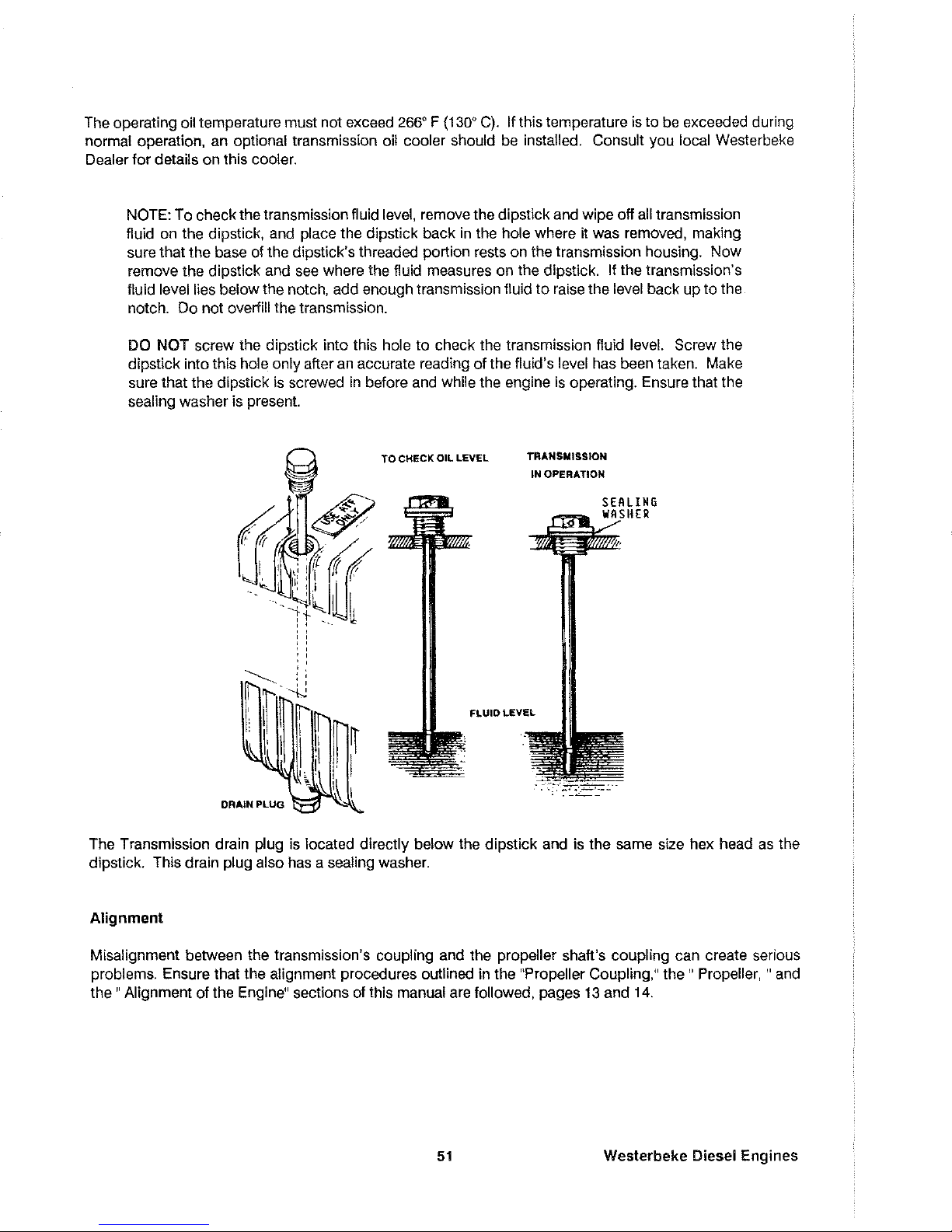
The operating oil temperature must not exceed
266'
F (130'
C).
If this temperature
is
to
be
exceeded during
normal operation, an optional transmission oil cooler should
be
installed. Consult you local Westerbeke
Dealer for details on this cooler.
NOTE: To check the transmission fluid level, remove the dipstick and wipe off
all
transmission
fluid on the dipstick, and place the dipstick back
in
the hole where ~ was removed, making
sure that the base of the dipstick's threaded portion rests on the transmission housing. Now
remove the dipstick and
see
where the fluid measures on the dipstick. If the transmission's
fluid level lies below the notch, add enough transmission fluid
to
raise the level back up to the
notch. Do not overfill the transmission.
DO NOT screw the dipstick into this hole to check the transmission fluid level. Screw the
dipstick into this hole only after
an
accurate reading of the fluid's level has been taken. Make
sure that the dipstick
is
screwed
in
before and while the engine
is
operating. Ensure that the
sealing washer
is
present.
~
_.....",I~
I
DRAIN
PLUG
TO
CHECK OIL LEVEL
TRANSMISSION
IN OPERATION
FLUID LEVEL
LING
HER
The Transmission drain plug
is
located directly below the dipstick and
is
the same size hex head as the
dipstick. This drain plug also has a sealing washer.
Alignment
Misalignment between the transmission's coupling and the propeller shaft's coupling can create serious
problems. Ensure that the alignment procedures outlined in the "Propeller
Coupling,"
the"
Propeller, "
and
the"
Alignment of the Engine" sections of this manual are followed, pages 13 and 14.
51
Weslerbeke Diesel Engines
Page 54

Controls
The only controls required
to
operate the transmission
is
a single lever remote control cable. The cable
should be attached to the gear box lever using the cable bracket supplied with the
unit
Both the gear box
lever and the remote control lever must be in the NEUTRAL position when the cable
is
attached
to
the gear
box
lever. This allows the remote cable
an
equal throw distance to shift the gear box into
FORWARD
or into
REVERSE
from the NEUTRAL posttion without running out of cable. Allow approximately 1.18 inches
(1
3/16)
of cable throw from the NEUTRAL position on the transmission's gear box lever
to
the each of the
two
drive
positions.
NOTE: If the throw distance (or travel) of the remote cable
is
too
short, the gear box lever
cannot fully engage the transmission into
FORWARD
or
REVERSE.
In this situation, the
transmission's clutch plates will wear prematurely and the transmission will eventually fail.
Minimum
Travel (Inner
nole
uSed)
,
1,18"
N
118"
/
30mm
30mm
i I
, . 0
GD\
J 0 I j
----
~·-"'-.CC=-~
...
-=:·
TItto~~----~-~-~~-
~-~~,,'
.~~@-
-
7f-:
,:
J
G5
ii:'~!
/
"'j
t...-;.,
'"
" I "
,-
,
'I
I
I '
Shllt
Cable
AttaChment
Iram Rear
11
~--
,
o
o
020
tncnes
Shltt
Arm
Securing
Boll
NOTE: Excessive throw distance
in
the remote control lever
is
not detrimental to the transmission. Note that the position of the remote control lever should align with the NEUTRAL marking on its bracket when the transmission
is
really in NEUTRAL.
Shifting
To shift the transmission from NEUTRAL into FORWARD, exert a heavy
push
to the remote control lever. A
gentle throw may not carry enough force to actually shift the transmission's internal gears. A gentle throw
is
signalled by the transmission not engaging into the desired drive, Make sure the remote control lever
is
lubricated at lease once each operating season. Shift the transmission while the engine
is
running at 1200
rpm or below, The clutch pack within the transmission makes
an
audiable "clunk" when engaging into gear.
Westerbeke Diesel Engines
52
Page 55

CAUTION
NEVER remove or loosen the four-bolt gear box lever cover from transmission. The position
of this
plate and the actuating lever inside of the transmission has been finely adjusted at the
factory
to
ensure equal throw distance of internal mechanisms. Loosening of this cover's
capscrews voids the transmission's warranty.
Sailing Operation
The HBW 50 transmission can be left in its NEUTRAL position while sailing. Leaving the transmission
in
NEUTRAL while sailing alleviates unnecessary drag on the vessel because the propeller
is
able to freewheel
(spin). However, should the operator wish
to
stop the rotation of the propeller shaft while under sail, this can
be done by
placing the transmission into
REVERSE
to
lock the propeller shaft.
Service
If
any seal on the transmission shows signs of leaking, have the transmission looked at
by
a qualified Wester-
beke
Dealer. This problem, especially concerning the rear seal, is often contributed to an improper align-
ment of the transmission's coupling and the propeller shaft's coupling. Refer to the "Alignment
olthe
Engine"
section of this
manual, page
13.
Recommended
Propeller Size
Propeller
Recommendations
(using HBW
50 transmission
2:
1 reduction)
Propeller Recommendations
(using
optional HBW
50
transmission with
2.5:1
reduction)
2-
12
0 x 6 P - blade or
11
0 x 6 P -3 blade
Propeller should allow
the engine to reach
its
full rated
RPM
(3600 + 000 - 100) at full open
throttle while underway.
120
x 8 P
-tlade
or
12
0 x 6 P - 3 blade
Propeller should allow
the engine
to
reach
its
full rated
RPM
(3600 + 000 - 100) at full open
throttle while underway.
53
Westerbeke Diesel Engines
Page 56

THE BW 3 TRANSMISSION
General
The
BW
3 transmission rotates opposite to the engine when the transmission
is
in
FORWARD
gear. When
the transmission
is
engaged in
FORWARD,
the input power
is
transmitted to the output shaft
by
helical spur
gears. When the transmission
is
engaged
in
REVERSE,
the input power
is
transmitted
to
the output shaft by
a high-performance roller chain. This feature makes the transmission suitable
for
a single-lever remote con-
trol with a rod linkage, such as a Morse or Bowden cable. For safety reasons, the transmission
is
NOT filled
with lubricating oil for shipment. Before leaving the factory, however, each transmission
is
thoroughly tested
with lubricating oil in the transmission. This testing, among other things, provides
all
internal parts with a
coating of lubricating oil. This fluid acts
as
a preservative, providing reliable protection against corrosion
for at least one year
if the transmission
is
properly stored.
Lubrication
The
BW
3 transmission
is
an
immersion-lubricated type. Fill the transmission up to or near the
top
of
the
machined notch cut on the dipstick with approximately 0.37
U.S.
quarts (0.32 liters)
of
etther
SAE
20Wj20
or
W30
engine oil. Do not mix
SAE
grades. Do not use multi-grade oils. Use
an
oil having
an
API
specifica-
tion of
CC, CD,
SC,
or
SE.
DIPSTICK/FIll
PORT
Change the transmission oil after the first
30
hours of engine operation and thereafter every
250
hours (or
once per year, minimum). The
BW
3 transmission has a drain plug for draining the old transmission fluid.
To ensure that most of the old oil
is
drained from the transmission, run the engine
in
NEUTRAL for ap-
proximately
10
to
15
minutes so the transmission oil may warm and flow better from the transmission. This
Westerbeke Diesel Engines
54
Page 57

transmission oil may also be removed by inserting a small tube through the dipstick opening (where the transmission oil
is
added) and attaching a pump onto the tube so the old oil may be sucked out,
The operating oil temperature must not exceed
266' F (130' C), If this temperature
is
to
be exceeded
during normal operation,
an
optional transmission fluid cooler should be installed, Consult you local
Westerbeke Dealer for details on this cooler,
NOTE: To check the transmission fluid level, remove the dipstick and wipe off
all
transmission
oil on the dipstick, and place the dipstick back in the hole where it was removed, making sure
that the dipstick's rubber head
is
properly inserted into the oil port, Now remove the dipstick
and see where the oil measures on the dipstick, If the transmission's oil level lies below the
notch, add enough transmission oil
to
raise the level back up
to
the notch, Do not overfill the
transmission,
DO
NOT
force the dipstick into the oil port to check the transmission oil level. Excessive pres-
sure can ruin the dipstick, Make sure that the dipstick
is
properly inserted into the oil port
before and while the engine
is
operating,
Alignment
Misalignment between the transmission's coupling and the propeller shaft's coupling can create serious
problems, Ensure that the alignment procedures outlined in the "Propeller Coupling,"
the"
Propeller, " and
the"
Alignment of the Engine" sections of this manual are followed, pages
13
and
14,
Controls
The only controls required to operate the transmission
is
a single lever remote control cable, The cable
should be attached to the gear box lever using the cable bracket
supplied with the unit. Both the gear box
lever and the remote control lever must be in the NEUTRAL
pOSition
when the cable
is
attached to the gear
box lever, The shift cable when properly adjusted should
allow for an equal throw of the transmission shift
lever into FORWARD or
REVERSE
from the NEUTRAL position without running out of cable, Allow ap-
proximately 1 1/2 inches of cable throw from the NEUTRAL position on the transmission's gear box lever to
the each
of
the
two
drive positions,
Minimum
Travel
{mner hole
usedj
N
1
1/2 1 1/2
/
Shit!
Cable
AttaChment
tram
Rear
55
Westerbeke Diesel Engines
Page 58

NOTE: If the throw distance (or travel) of the remote cable
is
too
short, the gear box lever
cannot fully engage the transmission into
FORWARD
or
REVERSE.
In this situation, the
transmission's internal gears will wear prematurely and the transmission may over heat.
NOTE: Excessive throw distance
in
the remote control lever
is
not detrimental
to
the transmission. Note that the position of the remote control lever should align with the NEUTRAL marking on its bracket when the transmission
is
really in NEUTRAL.
Shifting
To shift the transmission from NEUTRAL into FORWARD, exert a
heavy
push
to
the remote control lever. A
gentle throw may not carry enough force
to
actually shift the transmission's internal gears. A gentle throw
is
signalled by the transmission not engaging into the desired drive. Make sure the remote control lever
is
lubricated at lease once each operating season. Shift the transmission while the engine
is
running at 1200
rpm or below.
CAUTION
NEVER
remove or loosen the two-bolt gear box shift lever cover from transmission. The position of this plate and the actuating lever inside of the transmission has been finely adjusted at
the factory
to
ensure equal throw distance
of
internal mechanisms. Loosening
of
this cover's
capscrews voids the transmission's warranty.
Sailing
Operation
The
BW
3 transmission should be left
in
its NEUTRAL position while sailing. Leaving the transmission in
NEUTRAL while sailing alleviates unnecessary drag on the vessel because the propeller is able to freewheel
(spin). However,
if the transmission
is
left
in
its
FORWARD
gear while sailing, the transmission will not be
damaged. (Leaving the transmission
in
NEUTRAL
is
just good sailing practice.)
Service
If
any
seal
on the transmission shows signs of leaking, have the transmission looked at by a qualified Wester-
beke Dealer. This problem, especially concerning the rear
seal,
is often contributed
to
an improper align-
ment
olthe
transmission's coupling and the propeller shaft's coupling. Refer to the "Alignment
01
the Engine"
section of this manual, page 13.
NOTE: Never loosen the four gear box lever cover screws, except in the course
of
qualified
servicing; this upsets critical adjustments. Disassembly of the transmission
in
the field
is
not
recommended.
If an overhaul or repair
is
needed, the work should be done by Westerbeke
or an authorized Westerbeke service center.
Recommended
Propeller Size
Propeller Recommendations
(using BW 3 transmission
2:1
reduction)
Westerbeke Diesel Engines
2-
12
D x 6 P - blade or
11
D x 6 P - 3 blade
Propeller should allow the engine
to
reach
its full rated
RPM
(3600 + 000 - 100) at full open
throttle while underway.
56
Page 59

ENGINE TROUBLESHOOTING
Introduction
The tables which follow indicate troubleshooting procedures based upon certain problem indicators, the
probable causes of the problems, and the recommendations to overcome these problems.
Note that the engine's control
system (electrical system)
is
protected
by
a 20-Ampere manual reset circuit
breaker located on the rear lifting bracket.
Problem
Key switch
ON
but no panel or
test function.
PREHEAT switch
is
de-
pressed: no preheat
solenoid activation:
no electric
fuel pump or
alternator excitation.
Probable Cause
1.
Battery OFF.
2.
20 Amp circuit
breaker
is
tripped.
3. Loose battery
cable connection
1.
Faulty solenoid,
connections or switch.
2.
Faulty connection or
tripped
10
Amp breaker
on the I terminal on the
preheat solenoid.
57
Verification/Remedy
1.
Turn Battery ON.
2.
Reset the breaker
by
pushing in the button.
3. Check the
+ connection
to
the starter and the -
connection
to
the ground
stud on the
bell housing.
1.
Connection for
12
volts
at
S terminal of the solenoid
is.
faulty.
1. Check the preheat switch.
2. Check for
12
volts at the
10
Amp breaker. Check
for
12
volts at fuel lift pump
and at the R terminal on the
alternator when the preheat
button
is
pushed.
Wes!erbeke Diesel Engines
Page 60
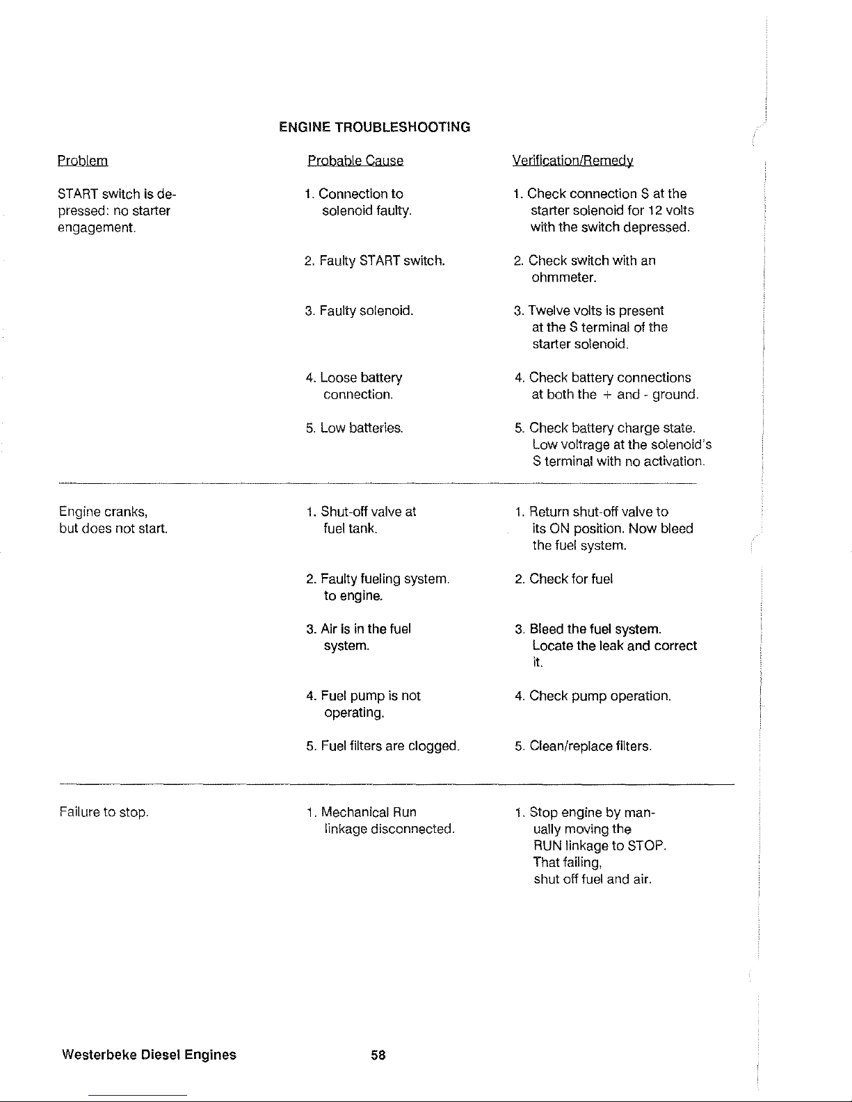
Problem
8T
ART
switch
is
de-
pressed: no starter
engagement.
Engine cranks,
but does not start.
Failure
to
stop.
Westerbeke Diesel
Engines
ENGINE TROUBLESHOOTING
Probable Calise
1.
Connection
to
solenoid faulty.
2. Faulty 8T
ART
switch.
3. Faulty solenoid.
4. Loose battery
connection.
5.
Low batteries.
1.
Shut-off valve at
fuel tank.
2. Faulty fueling system.
to engine.
3. Air
is
in the fuel
system.
4.
Fuel pump
is
not
operating.
5.
Fuel filters are clogged.
1.
Mechanical
Run
linkage disconnected.
58
verification/Remedy
1. Check connection S at the
starter solenoid for
12 volts
with the switch depressed.
2.
Check
SWitch
with an
ohmmeter.
3.
Twelve volts
is
present
at the
S terminal of the
starter solenoid.
4.
Check battery connections
at both the
+ and - ground.
5.
Check battery charge state.
Low voltrage at the solenoid's
S terminal with no activation.
1.
Return shut-off valve
to
its ON position.
Now
bleed
the
fuel system.
2. Check
for
fuel
3. Bleed the fuel system.
Locate the
leak and correct
it.
4.
Check pump operation.
5.
Clean/replace filters.
1.
Stop engine by man-
ually moving the
RUN
linkage
to
STOP.
That failing,
shut off
fuel and air.
Page 61

Problem
Engine
Stops.
Battery runs down.
Probable
Cause
1.
Fuel starvation.
Fuel shu1-off is turned
OFF.
2.
Fuel pump is
inoperative
3.
Water is in the
fuel.
4.
Exhaust system is
restricted.
1 . Alternator
ou1pu1.
is low.
2.
Faulty alternator.
3.
Bad battery
connections.
59
YerificationlBemedy
1.
Check
to
see that the
shu1-off valve at the
fuel tank is
ON.
2.
Inspect the fuel pump for
12 volt and
to
see
if
it is
pumping.
3.
Pump water
ou1
of the
bottom
of
the fuel tank(s) and
change the fuel filters and
bleed the fuel system.
4.
Check exhaust system for
some type
of
blockage
such as carbon buildup at
the exhaust elbow.
Check
for a fault
in
the muffler.
Check for a collapsed
exhaust hose.
1.
Check drive belt tension.
Make an
Ou1pu1
check
wtth a voltmeter at the B +
terminal
on
the alternator.
2.
Voltage leak through
the alternator when not
operating.
3.
Connections are corroded
or
loose at the battery
orland
at
the engine.
Westerbeke
Diesel
Engines
Page 62

MAINTENANCE AND ADJUSTMENTS
Introduction
This section contains a scheduled preventive maintenance program and several adjustment procedures the
owner/operator can perform without the benefit of sophisticated and expensive tools and instruments,
Preventive
Maintenance
Perform the preventive maintenance in accordance with the schedules listed in the following paragraphs,
Adherence
to
these schedules will ensure the equipment
is
maintained in the best possible condition and
that
it
will perform
to
expectations, Those items marked by
an
asterisk
(*)
are recommended to be per-
formed
by
an authorized dealer or distributor.
Daily (before each use)
1,
Check the oil sump level. Maintain the oil level
at
or
near upper level mark on dipstick,
2,
Check the coolant level in the plastic recovery tank, Maintain this level at
or
above the level marked
ADD,
3,
Check the transmission's lubricant level, and add additional lubricant as needed,
4,
Visually inspect the unit; check for loose bells, chafed or broken wires, loose brackets and fittings,
damaged hoses, loose clamps, and other equipment not properly secured, This check should include
the propeller shaft coupling to the transmission's output flange,
5,
Check the fuel supply, Fill tank(s) with a good grade
of
No, 2 dieselluel,
if
required,
6,
Check the primary filter/water separator. Drain and service
as
required,
(A
primary iilterjwater separator
is optional, but strongly recommended,)
7,
Check the engine's gauges or lights for proper oil pressure, operating temperature, and starting bat-
tery charging
voltage once the engine
is
operating,
8,
Check the alternator's output gauge (if installed) for proper DC voltage,
Monthly
Check the condition
of
the zinc anode in the heat exchanger's
sea
water
circuit
Clean or replace the anode,
as
required, Keep the area inside the heat exchanger clean
01
zinc anode debris,
Servicing After Initial
50
Hours
01
Operation
1,
Change the engine's lubrication oil and oil filter,
2,
Replace the fuel filter element in the electric fuel lift pump and
in
the optional water/sediment separator,
if
a separator has been installed,
Westerbeke Diesel Engines
60
Page 63

*3. Torque the cylinder head boits.
*4. Adjust
valve clearances.
5.
Adjust the alternator and water pump drive belt tension,
IT
required.
6.
Lubricate the throttle, the
RUN
linkage cable, and the transmission's remote control cable.
7.
Change the transmission's transmission fluid
IT
your engine is equipped with a HBW 50 transmission, or
change the transmission oil
IT
your engine is equipped with a BW 3 transmission.
Servicing
After
Every
100
Hours
of
Operation
1.
Change the engine's lubrication oil and oil filter.
2.
Adjust the alternator and water pump drive belt tension,
IT
required.
3.
Check the transmission fluid
or
oil level.
Servicing
After
Every
250
Hours
of
Operation
1.
Replace the fuellilter elements in Ihe electric fuel lift pump and in the optional water/sediment separator.
2.
Change the transmission's transmission fluid
IT
your engine is equipped with a HBW 50 transmission, or
change the transmission oil
if
your
engine is equipped with a BW 3 transmission.
Servicing
After
Every
500
Hours
01
Operation
*1. Torque
the
cylinder head bolts.
*2. Adjust the valve clearances.
3.
Drain, flush, and relill the fresh water cooling system. The illustration
on
page 5 shows the heat ex-
changer and
the zinc anode location. The drain plug for the fresh water system is next
to
the zinc anode.
*4. Check the
condition
01
the starler motor drive pinion; lubricate the pinion.
5.
Check the
resiste!11ce
of the
glow
plugs. (.4
to
.6 ohms)
NOTE: Items highlighted by an asterisk
(*)
should be performed
by
a competent mechanic.
61
Westerbeke
Diesel
Engines
Page 64

Servicing
After
Every
800
Hours
01
Operation
*1. Remove and check fuel injectors.
I njector spray pressure:
1991
psi +
140
psi
(140 kglcm
2
+
10
kglcm
2
)
Eliminate undesirable injection conditions including
after dripping.
*2. Check the engine's compression pressure.
Remove each
glow
plug and
check
each
cylinder's compression pressure. The engine's
cranking speed
is
at 280 rpm.
Standard
Minimum
,
POOR
~~~f~~~:~_~.,~~~.
____
~[j)J\
GOOD
455
psi
(32
kg/cm
2
)
369.7 psi
(26 kglcm
2
)
{Maximum difference between cylinders: 35.5 psi (2.5 kg/cm
2
)
*3. Check the battery-charging alternator for proper operation.
*4. Check the tightness
of
bolts, nuts, and clamps.
Servicing
After
Every
1000
Hours
of
Operation
1.
Remove, clean, and pressure test the primary heat exchanger.
(A
local automotive radiator shop should
be able to clean and test the heat exchanger.)
NOTE: Operating in silty and/or tropical waters may require that a heat exchanger cleaning
be performed more often than every
1000 hours.
*2. Check the injection pump's timing.
Westerbeke Diesel
Engines
62
Page 65

Torquing Cylinder Head Bolts
Tighten the cylinder head bolts according to the sequence shown in the illustration shown
to
the right. Make
sure the engine
is
cold when this
is
done. Loosen one head bold one-half turn and then tighten
it
between
56
to
59
Ib-ft (7.8
to
8.2
kg-m). Then proceed to the next head bolt
in
the sequence numbering shown.
Valve Clearance Adjustment
NOTE: Retorque the cylinder head bolts before adjusting the engine's valves.
1.
Remove the rocker arm cover.
2.
Position the No.1 piston at Top Dead Center
(TDC)
of its compression stroke. To
do
this, align the timing
mark on the gear case with that on the crankshaft pulley (refer
to
the photograph shown below).
Nowad-
just the NO.1 piston's intake and exhaust valves.
MARK
ON
GEAR-~.
~
CASE
++-+++-+~-T-
63
25"
BlOC
INJECTION
PUMP
TIMING
MARK
TOP
DEAD
CENTER
ALIGNMENT
MARK
Westerbeke Diesel Engines
Page 66

3.
Facing the front
of
the engine, rotate the crankshaft 170' clockwise
to
position the
No.2
piston at
TOC
of
its compression stroke. Now adjust the
No.2
piston's intake and exhaust valves.
NOTE: Adjust
all
valves
to
0.0098 inches (0.25 mm) with the engine cold.
ADJUST
VALVES
TO
8.8898
INCHES
[8.25
~MJ
Adjusting a valve's clearance with a feeler gauge.
Westerbeke
Diesel Engines
64
Page 67

Injection
Pump
Timing
Adjustment
(Spill
Timing)
If your engine's fuel injection timing is not properly adjusted, the engine will not operate properly and will be
difficult to start. Have the injection pump delivery rate checked
by
a well established fuel injection shop. Ad-
just the injection timing as follows:
NOTE: The fuel lever (throttle) must be in the
RUN
position while making the adjustment or
no fuel will flow to the fuel injection pump.
Refer
to
the illustration below when servicing the fuel injection pump. First remove the high-pressure fuel
line from between the No.1 injector and the No.1 fuel delivery valve holder. Remove the No.1 fuel delivery
valve holder and remove the delivery valve spring beneath the holder. Reinstall only the delivery valve holder
and reattach the hight pressure fuel line
to
the delivery holder. Attach it so that the end that would connect
to
the fuel injector is pointing away from the engine.
Fuel
will flow from this line during the timing check.
DELIVERY
VALVE
HOLDE!
DELIVERY
VALVE
SPRING
DElI\lERY
VALVE
B A
II II
EL
....-"'-6"1t\
A,R
BLEED-IIIG
SCREW
PlDNHR
1i~~~2~LCQ"TROl
RAU
CONTROL
PUlIOM
PlUNGER
SPIII1I6
TAPPET
Cutaway View
of
the W 12B TWO's Fuel Injection Pump
Move the throttle lever to mits full open position and
operate the electric lift pump. Rotate the crankshaft
clockwise (as viewed from the front). catching the fuel
from the No.1 fuel line, until the instant the fuel com-
pletely stops flowing (no drips).
At
this instant, the
250 BTDC timing mark on the crankshaft pulley
should be directly aligned with the timing indicator on
the front
of
the gear case (see the illustration
to
the
right).
65
MIIRK
ON
GEIIR-_
INJECTION
TIMING
MIIRK
ON
PULLEY
CIISE
~~~~tV~~
Westerbeke Diesel Engines
Page 68

If the specified injection timing
(250 BTDG)
cannot be attained, adjust the timing by increasing or decreas-
ing the thickness of the injection pump mounting shim. Changing the shim thickness
by
0.004 inch
(0.01
mm)
changes the injection timing
by
approximately one degree. To advance the timing, decrease the shim thick-
ness,
as
required. To retard the timing, increase the shim thickness, as required. Refer
to
your engine's
parts List for shim part numbers.
Westerbeke
Diesel
Engines
DELIVERY
VALVE
HOLDER
INJECTION
PUMP
ADJUSTING
SHIM
Fuel Injection Pump wtth
an
Adjusting Shim
66
Page 69

LAY-UP
AND
RECOMMISSIONING
General
Many owners rely on their boatyards
to
prepare their craft, including engines and generators, for lay-up
during the off-season
or
for
long periods of inactivity. Others prefer
to
accomplish lay-up preparation them-
selves.
The procedures which
follow will allow you
to
perform
your
own lay-up and recommissioning,
or
to
use as
a check
list if others
do
the procedures.
These procedures should afford your engine protection during
a lay-up and also help familiarize you with
the maintenance needs of
your
engine.
If you have any questions regarding lay-up procedures, call
your
local servicing dealer; he will be more than
willing
to
provide assistance.
Propeller Coupling
The transmission and propeller half couplings should always be opened
up
and the bolts removed when-
ever the boat is hauled out of the water
or
moved from land
to
water, and during storage
in
a cradle. The
flexibility of the boat often puts
a severe strain on the propeller shaft
or
coupling,
or
both, while the boat
is
taken
out
or
put in the water.
In
some cases, the shaft has actually been bent
by
these strains. This does
not
apply
to
small boats that are hauled out of the water when not
in
use, unless they have been
dry
for a
considerable period of time.
Fresh
Water
Cooling
System
A 50-50 solution
of
antifreeze and fresh water is recommended for use
in
the fresh water cooling system at
all times. This solution
may
require a higher concentration
01
antifreeze, depending on the area's winter
climate.
Check the solution
to
ensure that the antifreeze protection is adequate.
Should more antifreeze be needed, drain an appropriate amount from the engine block and add a more concentrated
mixture. Operate the engine
to
ensure a complete circulation and mixture of the antifreeze con-
centration throughout the cooling system.
Now
recheck the antifreeze solution's strength.
Lubrication
System
With the engine warm, drain all the lubricating oil from the oil sump. Remove and replace the oil filter. (Place
some paper towels and a plastic bag around the filter
to
catch the oil during its removal.)
When installing the new oil filter, be sure
to
apply a small amount of oil on the rubber sealing gasket at the
base
of
the lilter. Fill the sump with the correct amount of oil for
your
engine. (Refer
to
the"SYSTEM
SPECIFICATIONS"
section of this manual, page
8.)
Use an oil with an
API
specification of CC
or
CD.
Run
the engine and check
for
proper oil pressure and ensure that there are
no
leaks.
67
Westerbeke
Diesel
Engines
Page 70

CAUTION
Do
not
leave the engine's old lubricating oil in the sump over the lay-up period. Lubricating
oil and combustion
deposITs combine
to
produce harmful chemicals which can reduce the
life
of
your
engine's internal parts.
Fuel
System
Top off
your
fuel tanks
WITh
No.2
diesel fuel. Fuel additives should be added at this time
to
control algae
and condition the fuel. Care should be taken that the additives used are compatible with the primary filter/water separator used in the system. Change the element in your primary fuel filter/water separator, if the
fuel system contains one, and clean the separator sediment bowl.
Change the fuel filter elements on the engine and bleed the fuel system, as needed. Start the engine and
allow it
to
run for 5 -10 minutes
to
ensure that no air is left in the fuel system. Check for any leaks that
may
have been created in the fuel system during this servicing, correcting them as needed.
Sea
Water
Circuit
Close the thru-hull sea cock. Remove the sea water intake hose from the sea cock. Place the end of this
hose into a
5-gallon bucket of clean fresh water. Before starting the engine, check the zinc anode found in
the primary heat exchanger on the engine and
clean
or
replace
IT
as required. Clean the sea strainer, if one
is installed in the inside of the
hull.
Start
the engine and allow the sea water pump
to
draw fresh water through the system. When the bucket
is empty, stop the engine and refill the bucket with an antifreeze solution
slightly stronger than needed for
winter freeze protection
In
your area.
Start the engine and allow all of this mixture
to
be drawn through the sea water system. Once the bucket
is empty, stop the engine. This antifreeze mixture should protect the sea water circuit from freezing during
the winter lay-up, as
well as providing corrosion protection.
Remove the impeller from your sea water pump (some antifreeze mixture will accompany
it,
so catch it
in
a
bucket). Examine the impeller. Acquire a replacement,
if needed, and a cover gasket. Do not replace the
impeller (into the pump) until recommissioning, but replace the cover and gasket.
Intake
Manifold
and
Through-Hull
Exhaust
Place a clean cloth, lightly soaked in lubricating oil, in the opening of the intake manifold
to
block the open-
ing. Do
not
shove the cloth out of sight. (If it is not visible at recommissioning, and an attempt is made
to
start the engine, you
may
need the assistance of a servicing dealer.) Make a note
to
remove the cloth prior
to
start-up. The through-hull exhaust part can be blocked
in
the same manner.
Starter
Motor
Lubrication and cleaning
of
the starter drive pinion is advisable, if access
to
the starter
permITs
ITS
easy
removal. Ensure that the battery connections are shut off before attempting
to
remove the starter. Take care
in
properly replaCing any electrical connections removed from the starter.
Westerbeke Diesel
Engines
68
Page 71

Cylinder
Lubrication
It
is
not necessary
to
remove the fuel injectors from the cylinder head
to
squirt light lubricating oil into the
cylinders for the few months of normal lay-up. However,
if
you anticipate a longer lay-up period (12 months
or more), we recommended that this procedure be performed. The
light oil in the cylinders will prevent the
pistons rings from sticking
to
the cylinder walls. Ensure that you have replacements for the injector and
return
line sealing washers.
Spares
Lay-up time provides a good opportunity to inspect your Westerbeke engine to see
if
external items such
as drive belts
or
coolant hoses need replacement. Check your basic spares kit and order items not on hand,
or replace those items used during the lay-up, such
as
filters and zinc anodes.
Batteries
If batteries are
to
be left on board during the lay-up period, ensure that they are fully charged, and will remain
that way, to prevent them from freezing.
If there exists any doubt that the batteries will not remain fully
charged, or that they will be subjected to severe environmental conditions, remove the batteries and store
them
in
a warmer, more compatible environment.
Recommissioning
The recommissioning
of
your Westerbeke engine after a seasonal lay-up generally follows the same proce-
dures as those presented
in
the "PREPARATIONS
FOR
STARTING" section, page
21,
regarding preparation
for starting and normal starts. However, some
of
the lay-up procedures will need
to
be counteracted before
starting the engine.
1.
Remove the oil-soaked cloths from the intake manifold and from the through-hull exhaust port.
2.
Remove the sea water pump cover and gasket and discard the old gasket. Install the sea water pump
impeller removed during lay-up (or a replacement, if required). Install the
sea
water pump cover with a
new cover gasket.
IWARNING~
Wear rubber gloves, a rubber apron, and eye protection when servicing batteries.
Lead acid batteries emit hydrogen, a highly-explosive gas, which can be ignited by electrical
arcing or a
lighted cigarette, cigar, or pipe. Do not smoke or allow an open flame near the
battery being serviced.
Shut off all electrical equipment
in
the Vicinity
to
prevent electrical ar-
cing during servicing.
3.
Reinstall the batteries that were removed during the lay-up, and reconnect the battery cables, making sure
the terminals are clean and that the connections are tight. Check to ensure that the batteries are
fully-
charged.
69
Westerbeke Diesel Engines
Page 72

4.
Check
the
condITion of the zinc anode in the sea water circuit and clean
or
replace the anode as needed.
Note that
IT
is not necessary
to
flush the antifreeze/fresh water solution from the sea water coolant sys-
tem. When the engine is put
Into operation, the system will self-flush
in
a short period of time with no ad-
verse affects.
5.
Start the engine in accordance with procedures in the "PREPARATIONS
FOR
STARTING" section of this
manual, page
21.
Westerbeke
Diesel
Engines
70
Page 73

TABLE OF STANDARD HARDWARE TIGHTENING TORQUES
Unless stated otherwise for a specific assembly, use the following torque values when tightening standard hardware.
Grade 4T
6mm
bolt head/nut
8mm bolt head/nut
10mm bolt head/nut
10mm bolt head/nut
12mm bolt head/nut
12mm bolt head/nut
12mm bolt head/nut
13mm bolt head/nut
14mm bolt head/nut
14mm bolt head/nut
16mm bolt head/nut
16mm bolt head/nut
Grade
6T
6mm
bolt head/nut
8mm
bolt head/nut
10mm
bolt head/nut
10mm bolt head/nut
12mm bolt head/nut
12mm bolt head/nut
12mm bolt head/nut
Grade
7T
8T
and 8,8
6mm
bolt head/nut
8mm bolt head/nut
10mm bolt head/nut
10mm bolt head/nut
12mm bolt head/nut
12mm bolt head/nut
12mm bolt head/nut
13mm bolt head/nut
14mm bolt head/nut
14mm bolt head/nut
16mm bolt head/nut
16mm bolt head/nut
Grade
5 capscrew
1/4
UNC
1/4 UNF
5/16 UNC
5/16 UNF
3/8 UNC
3/8 UNF
7/16 UNC
7/16 UNF
1/2 UNC
1/2 UNF
Pitch
1.25
1.25
1.5
1.25
(ISO)
1.5
1.75
1.5
1.5
2
1.5
2
1.25
1.25
1.5
1.25 (ISO)
1.5
1.75
1.25
1.25
1.5
1.25
(ISO)
1.5
1.75
1.5
1.5
2
1.5
2
71
Ib-lt
2.9 -
5.1
7.2 - 11.6
13.7 - 22.4
13.0 - 21.7
25.3
- 39.8
25.3
- 39.8
21.7
- 36.2
32.5
- 50.6
36.2 - 57.9
34.0 - 55.7
54.2
- 79.6
51.4
- 76.7
4.3 - 6.5
10.8 - 15.9
21.7-
32.5
19.5
- 30.4
36.2 - 57.9
36.2
- 50.6
34.7 - 49.2
5.8 - 8.7
14.5-21.7
28.9 - 39.8
26.8 - 37.6
54.2 - 75.9
50.6 -
65.1
43.4 - 61.5
57.9 - 86.8
72.3
-108.5
68.7 -101.3
108.5
- 166.4
101.3 -159.1
9 -
11
11
-
13
18 -
20
21 -23
28 - 33
30 -
35
44
- 49
50
- 55
68 -
73
73
- 80
kg-m
0.4-0.7
1.0
- 1.6
1.9 -
3.1
1.8 - 3.0
3.5 - 5.5
3.5
- 5.5
3.0 - 5.0
4.5 - 7.0
5.0 - 8.0
4.7-
7.7
7.5-11.0
7.1
-10.6
0.6 - 0.9
1.5 - 2.2
3.0 - 4.5
2.7
- 4.2
5.0 - 8.0
5.0 - 7.0
4.8 - 6.8
0.8 - 1.2
2.0 - 3.0
4.0 -
5.5
3.7 - 5.2
7.5-10.5
7.0 - 9.0
6.0 -
8.5
8.0
-12.0
10.0 -15.0
9.5
-14.0
15.0 - 23.0
14.0 - 22.0
1.2 - 1.5
1.5-
1.8
2.5
- 2.8
2.9
- 3.2
3.7-4.6
4.1
- 4.8
6.1
- 6.8
6.9
- 7.6
9.4-10.1
10.1-11.1
Westerbeke Diesel EnginE
Page 74

TORQUE SPECIFICATIONS
Cylinder head bolt
(Ma)
* 25.3 - 28.9
3.5 -
4.0
(See
the"
Tightening
Cylinder
Head
Bolts"
section of this manual on page 63.)
Rocker cover nut
(Ma)
3.6 -
5.1
0.5 - 0.7
Connecting rod cap nut 23.1 - 25.3 3.2 - 3.5
Flywheel bolt 47.0 - 50.6 6.5 - 7.0
Crankshaft pulley nut (M24) 108.5
-144.7
15 - 20
Oil drain plug 36.2 - 43.4
5.0 - 6.0
Oil filter
7.9 - 9.4
1.1
- 1.3
(or tighten firmly
by
hand)
Nozzle holder
36.2 - 43.4 5.0 - 6.0
Nozzle holder and retaining nut 43.4 - 57.9 6.0 -
B.O
Glow plug 10.8 - 14.5
1.5 -
2.0
Starter B terminal nut (on
copper
stud) 7.2 - 8.7
1.0 - 1.2
* NOTE:
MB
indicates Metric, 8
mm
thread diameter
Westerbeke
Diesel
Engines
72
Page 75

SPARE PARTS
Since
a possibility exists in which the engine
may
need
to
be
serviced at sea
or
while in a port other than
your
home
port, certain spare parts should be kept on board
to
help minimize delays in
your
voyage. Please
refer
to
your
engine's Parts List for part numbers when ordering spare parts.
Listed
below are those spare parts that should be carried on board at all times.
1
. An I mpeller Kit
2.
A Fuel System hardware Kit
3.
An Electric Fuel Lift
Pump
Filter and a Secondary Fuel Filter.
4.
An Alternator/Sea Water Pump Belt
5.
Hose Clamps
6. A Spare Oil Filter with a Spare Quart of Diesel Service Engine Oil along with a Quart of Transmission
Lubricant and a
Gallon of Premixed Antifreeze.
Other parts, whose life expectancy cannot be accurately predetermined, should
be
carried on board (in ad-
dition
to
those listed above) especially if the vessel is
to
be taken on
long
ocean voyages. These parts are
listed below.
1.
Fuel Injectors
2.
Glow
Plugs
3.
Cooling System Hoses
4.
An Alternator
5.
A Starter
6.
A 20
Amp
DC Circuit Breaker
7.
An Electric Fuel Lift
Pump
8.
A Sea Water
Pump
9.
Battery Terminal Connectors
The spare parts
listed directly above are those
we
recommend be carried on board during long ocean
voyages.
You
may
wish
to
ask other boat owners
who
have similar crafts and
who
have completed long
ocean voyages as
to
what spare parts they carried on board and what parts were needed at specific times
of the voyage. From the
list provided directly above and from these inquiries,
you
can determine what spare
parts
may
be needed. In addition, ~ you are planning a long ocean voyage, consult
your
local Westerbeke
dealer for
a listing of the Westerbeke dealers located on
your
route.
73
Westerbeke
Diesel
Engines
Page 76

iNDEX
A
Adjustment, Injection Pump Timing
....
,..,. .....
,..
,.,.,.,.,.,.,.,. ,.,.,.,.,.,.,.,.,.. ,.,.65
ADJUSTMENTS,
MAINTENANCE AND ,.,.,.,.,.,.,.,.,.,.,.,.,.
....
,.,.,.,.. .
..
,.60
Adjustment, Valve Clearance ,..,.,.,.
..
,.,.,.,.,.,.,.
..
,.,.,.",.,.,.,.. ,.,.,.,.,..,.
.......
,.,.,.,..,.
..
,.,..,..,.. ,..,.,.,..63
Admirals Panel.,..,.
..
,.,..,..,.
..
,.,..,.,.,.,..,..,.,..,..,.,.,..,..,.
..
,..,... ,.,. ......
,.
...
,..,.,.,..,..,.
....
,. ,.
.....
,.
.... 24
ADMIRALS PANEL, DC WIRING DIAGRAM # 36844,.,.,..,..,..,.,.,.,.,.,.,..,.,.,..,.,.,.,..,.
..
,.,.,.,.,..,.,..,.,. 36 and 37
Alignment (BW 3 Transmission)
,.,..,.,.
..
,.,.,.,..,.
..
,..,..,.
..
,.,.
..
,.,.,.,..,..,..,.
..
,.,.,.,..,..,. ..... ,.,. .... ,..,..,..,.
...
,..,..,..,.,..55
Alignment
(HBW
50
Transmission) .,.,.,.,.,.,.,.,..,.,.,.,..,..,.,.,.,.,.,..,.
..
,..,.,.
...
,.",.
..
,..,..,..,..".,..,..,..,.,..,..,.,.
..
,..,..51
Alternator ...................................................................................................................................................... 33
Alternator and Water Pump Drive Belt
Tension,.,.,..,..,..,.,.,.,.,.,..,..,..,..,..,..,.,.,.,.,.,.,.,.,.,..,..,..,..,.,..,..,..,..,.,..42
Alignment
of
the Engine (Installation Checks). ,.,.,.,.,. ,..,.,.,..,.. ,.,.,..,. ,.,.,..,..,..,..,.. ,.,.,.,..,.. ,.,.,.,. ,.,.,.,. ,.,.,.,..,.
.13
ANTIFREEZE CONCENTRATION DATA ..........................
,.
..................................
,.
.................................... .40
Automatic Alarm System (Installation Checks) ,.,.,.,.,.,.,.,. ,.,.,.,.,.,.,.,.,.,.,.. ,.,.. ,.,.,.. ,.,.,.,.. ,.,.,.,..,.,.. ,.,.,. ,.,.,.. ,..18
B
Back-Pressure, Exhaust (Installation Checks) ..........
,.
................................................................................ 16
Batteries (Lay-up and Recommissioning) ................................................................................................... 69
Battery Specification ..........
,.
........................................................................
,.
........................................... ,..33
Belt Tension, Alternator and Water Pump Drive,.,.",.,.,.,.,.,.,.,.",.,.,.,.,.
..
,..,.,.,.,.,.,.,..,.,.,.,.,.,.,..,.,..,.,.,.,.,.,.,..42
Bolts, Engine (Installation Checks) ,.,.,.,.,.,.,. ,.,.,.,.,.",.,.
..
,.,.. ,.,.,.
..
,.,.,..,.
...
,.,.. ,.,.,.,..,.,. ,.".,..,.. ,.,.,.,.
..
,.,.,..,.
..
,.12
Bolts, Torquing Cylinder Head ,.,.,.. ,..,.,.,. ,..,.,. ,.,.,. ,.,.,..,..,.. ,.,.,..,.. ,.,.,. ,.,.,.. ,.,.,.,.. ,.,.,..,. ,.,.,.,.,.. ,.,.,.,..,..,..,.,.,.
.63
Break-in Procedures, Engine ...................................................................................................................... 28
BW 3
TRANSMiSSiON ................
,.
....................................
,.
......................................................................... 54
c
Captains Panel ...........................................
,.
...............................................................................................
.23
CAPTAINS PANEL, DC WIRING DIAGRAM # 38467,.,.
...
,..,.,.
..
,..,.,.,.,..,.,.
..
,.
..
,.,.,.,.
..
,.,.,.,.,.,.
..
,.,.,. 34 and 35
Change, Engine
Oil (to include filter) ,.,..,.,.,..,.,.,.,.,.,.,.,.,..,.,.,.
..
,.,..,..,..,.,.,..,.
..
,.,.,.,..,..,.,..,..,..,.,.,.,..,.,..,.,.
...
.48
Charging Voltage Test ................................................................................................................................. 38
CHECKS, INSTALLATION ,.,. ....
,..
,.
..
,.,.,.,.,.,.,. ,.,.,.,.,. ,.,.,.,..,.,. ,.,.,.
...
,.,.,. .... ,..,..,..,.,.,..,..,.,..,.. ,.,.,.,..,..,..
,.
...
,..,.1 0
CirCUIT,
Fresh Water ....
,.
............................................................................................................................... 39
Circuit,
Sea Water .................................
'"
...................................................................................................
.42
Circutt, Sea Water (Lay-up and Recommissioning) ,..,.,.,..,.,.,.,..,.,.
..
,.,.,..,.,.,.,.,.,..,.,.,.,.,.,..,.,.,.,.,.,.,.,.,.,.,.,..68
Clearance Adjustment, Valve ...................................................................................................................... 63
Cold Conditions, Starting Under
,.,.,.,.
,.
..
,.,.,.
...
,.,.,..,.. ,.,.,.,.,.,..,.. ,.,.,..,.. ,.,.,.,..,.
..
,.
....
,..
,.,.
..
,..,..
,.
...
,..,..,..,.
..
,.
,.29
CONCENTRATION
DATA,
ANTIFREEZE .................................................................................................... 40
Conditions, Starting Under Cold
...
,..
,..,..,.,.,.,..,.,. ,.",..,..,.. ,.,.,.. ".,.
..
,.,..,.,.,..,..,..,.,.,.. ,.,..,..,..,..,..,.. ".,.
..
,.,.,.
...
29
Conditions, Starting Under
Normal.,..,..,.
..
,.,..,.. ,.,.",.,.. ,..,.
..
,..,..,..,..,..,.. ,.,.,.,.
..
,.,.,..,..,.,..,.
..
,.,..,..,..,..,..,.,.,. ,.29
Connecting Pressure Sensing Devices
to
Oil Galleries (Installation Checks),.,.,..,..,..,.,.
...
,.
..
,.,.,.,.,.,.,..,.,.18
Controls (BW 3 Transmission)
,..
,.,.,.,. ,.,.,.,.,.,..,.,.,.. ,.,.,.,.,.,.. ,.,.,..,..,..,..,.,. ,.,.,.,.. ,.,.,..,..,. ,.,.,.,..,..,..,.. ,.,.,.,..,.
..
55
Controls (HBW 50 Transmission),..,..,.,.,.. ,.,.,.,.. ,.,.,.,.,.,.,.,..,..,..,.,. ,.,.,.,..,.,. ,.,.,.,.,.,..,..,.,.. ,.,.,.,..,..,..,.. ,.,.,..,. ,.52
Cooling System (Installation Checks) ,.,.,.,. ,.,.,. ,.,.,..,.. ,.,.,.,.
..
,..,.,.,. ,..,.,.,..,.
..
,..,.. ,.,.,..,. ".,..,..,..,.. ,..,.. ,.,.,.,.. ,..18
COOLING SYSTEM
.....
,.
.............................................................................................................................. 39
Cooling
System, Fresh Water (Lay-up and Recommissioning),.,.,.,.,.,..,.,.,.,.,.,.,.,..,..,.,..,..,..,.,.,..,.,.,.,..,..,.67
Control Circuit, Engine 12-Volt DC,.,.,.,.,.,.
...
,..
,.,.,.,.,.,.
..
,.,.. ,.,.,.,.,.,.,.,.. ,.,.,.
..
,.,.,.,.,.,..,.,..,..,.,.,..,..,.
...
,.,.,..,.. ,.33
Coupling, Propeller (Installation Checks) ,.,.,.,..,..,.,.,..,..,..,.,.,..,..,.,..,.,.,.,..,..,..,.,.,.,.,.,..,.
..
,.
..
,.,.,.
..
,..,.,.
...
,.,..13
Coupling, Propeller (Lay-up and Recommissioning) ,.,.,..,..,..".,..,.,.,.,.,..,..,..,.,.,.,.,..,.,..,..,.,.,.,..,..,..,..,.,.,.
..
67
Cylinder Head Bolts, Torquing
.................................................................................................................... 63
Westerbeke Diesel Engines
74
Page 77

Cylinder Lubrication (Lay-up and Recommissioning) ...............................................................................
69
CAUTIONS
ENGINE
NOT
SHIPPED WITH
OIL
........................................................................................ 10
LIFTING SLINGS ...................................................................................................................
11
SCOOP-TYPE
HULL
FITTINGS ............................................................................................. 18
PROLONGED CRANKING INTERVALS ................................................................................. 26
ENGINE SHUTDOWN ............................................................................................................ 28
PROLONGED CRANKING INTERVALS .................................................................................
31
DAMAGE
TO BATTERY
CiRCUiT
.......................................................................................... 33
QUICK-CHARGING BATTERY ............................................................................................... 33
ALTERNATOR
TESTING ....................................................................................................... 33
EXCESSIVE
BELT
TENSION ................................................................................................. 42
TRANSMISSION GEAR COVER ............................................................................................ 53
TRANSMISSION GEAR COVER ............................................................................................
56
D
DC Control
CirCUIT.
Engine 12-Volt .............................................................................................................
33
DC WIRING DIAGRAM # 36844 (ADMIRALS PANEL) .................................................................. 36 and 37
DC
WIRING DIAGRAM # 36467 (CAPTAINS PANEL) ................................................................... 34 and 35
DESCRIPTION OF INSTRUMENT PANELS ............................................................................................... 23
Description
of
Starting System ...................................................................................................................
22
Devices
to
oil Galleries. Connecting Pressure Sensing (Installation Checks) .......................................... 18
Diesel Engine. Understanding the ................................................................................................................ 4
Diesel Fuel ...................................................................................................................................................
30
DISCLAIMER. PRODUCT SOFTWARE.
........................................................................................................ 1
Domestic
Hot
Water .................................................................................................................................... 45
Drain.
Oil (Installation Checks) ................................................................................................................... 17
E
Electrical System (Installation Checks) ...................................................................................................... 19
ELECTRICAL
SySTEM ................................................................................................................................ 33
Elements. Replacing the Fuel Filter ............................................................................................................
31
Engine 12-Volt DC Control Circuit .............................................................................................................. 33
Engine.
Alignment of the (Installation Checks) .......................................................................................... 13
Engine. Break-in Procedures ...................................................................................................................... 28
Engine Bolts (Installation Checks) .............................................................................................................. 12
Engine. Diesel. Understanding the ............................................................................................................... 4
Engine. Foundation
forthe
(Installation Checks) ...................................................................................... 12
Engine
Oil .................................................................................................................................................... 47
Engine
Oil Change (to include filter) .......................................................................................................... 48
ENGINE TROUBLESHOOTING .................................................................................................................. 57
Equipment. Inspection of .............................................................................................................................. 2
Exhaust Back-Pressure (Installation Checks) ............................................................................................ 16
Exhaust.
Intake Manifold and Through-Hull (Lay-up and Recommissioning) .......................................... 68
Exhaust
System (Installation Checks) ........................................................................................................
15
Exhaust System Failures (Installation Checks) .......................................................................................... 17
75
Westerbeke
Diesel
Engines
Page 78

F
Failures, Exhaust System (Installation Checks) .........................................................................................
17
Filters, Fuel ...................................................................................................................................................
30
FORWARD ...................................................................................................................................................... 2
Foundation for the Engine ...........................................................................................................................
12
Fresh Water Circuit ......................................................................................................................................
39
Fresh Water Cooling System (Lay-up and Recommissioning) ..................................................................
67
Fuel, Diesel ...................................................................................................................................................
30
Fuel Filters ....................................................................................................................................................
30
Fuel Filter Elements, Replacing the .............................................................................................................
31
Fuel Injection Pump .....................................................................................................................................
32
Fuel System (Installation Checks) ...............................................................................................................
19
Fuel System (Lay-up and Recommissioning) .............................................................................................
68
FUEL SYSTEM .............................................................................................................................................
30
Fuel System, Priming the .............................................................................................................................
31
G
Galleries, Connecting Pressure Sensing Devices
to
Oil (Installation Checks) .......................................... 18
GENERAL ....................................................................................................................................................... 4
GENERAL SPECiFiCATIONS ........................................................................................................................ 7
H
HARDWARE TIGHTENING TORQUES, TABLE OF STANDARD ...............................................................
71
HBW
50
TRANSMISSION ............................................................................................................................
50
Head Bolts, Torquing Cylinder ....................................................................................................................
63
Hot Water, Domestic .................................................................................................................................. .45
INDEX ...........................................................................................................................................................
74
Injection Pump, Fuel .................................................................................................................................... 32
Injection Pump Timing Adjustment ............................................................................................................. 65
I nspection of Equipment ............................................................................
'"
................................................ 2
INSTALLATION CHECKS ............................................................................................................................ 10
I~STRUMENT
PANELS, DESCRIPTION OF ............................................................................................... 23
Intake Manifold and Through-Hull Exhaust (Lay-up and Recommissioning) ............................................
68
Intake System, Sea Water (Installation Checks) ......................................................................................... 19
L
LAY-UP AND RECOMMiSSiONING ............................................................................................................
67
Lifting, Rigging and (Installation Checks) ..................................................................................................
11
Location (Installation Checks) ..................................................................................................................... 10
Lubrication (BW 3 Transmission) ................................................................................................................
54
Lubrication, Cylinder (Lay-up and Recommissioning) ...............................................................................
69
Lubrication (HBW 50 Transmission) ........................................................................................................... 50
Lubrication System (Lay-up and Recommissioning) ................................................................................. 67
Westerbeke
Diesel
Engines
76
Page 79

LUBRICATION SYSTEM .........................................................................................................................
47
M
MAINTENANCE AND ADJUSTMENTS .......................................................................... . . ... 60
Manifold, Intake and Through-Hull Exhaust (Lay-up and Recommissioning) ...... ............... . ........
68
Motor, Starter (Lay-up and Recommissioning)
.... .... .... ....
...
....
..
....
.......
...
.... ....
....
..
............... ............ .
...
68
N
Normal Conditions, Starting Under ........................................................................................................... 29
o
Oil Change, Engine (to include filter) .................................................................................................
.48
Oil Drain (Installation Checks) ................................................... ..................................... .
...
17
Oil, Engine .................................................................................. ..................................................... .
.....
47
Oil Galleries, Connecting Pressure Sensing Devices
to
(Installation Checks) ......................... .
18
Oil Pressure ................................................................................................................................................
47
Operation, Sailing (BW 3 Transmission) ................................... ........................ ........................ . .........
56
Operation, Sailing (HBW
50
Transmission)..................................................................................... . .....
53
Ordering Parts ............................................................................................................................................. 4
p
Panel, Admirals ........................................................................................................................................... 24
Panel, Captains ..........................................................................................................................
'"
..............
23
PANELS, DESCRIPTION OF INSTRUMENT .............................................. _ ..............................................
23
Parts, Ordering .............................................................................................................................................. 4
Parts, Spare ............................................................................................. " ..................................................
73
PREPARATION
FOR
STARTING ............................... ................................ ............................ .
...
21
Pressure, Oil ..............................................................................................................................................
47
Pressure Sensing Devices
to
Oil Galleries, Connecting (Installation Checks) ..................... . ..... 18
Priming the Fuel System. .......
.... .... ....
.....
..... .......
.... ....
....... ..........
...
....
...
.... ....
.......
..
. .........
...
....
. ....
31
PROCEDURE, STARTING ........................................................................................................................
26
PROCEDURE, STOPPING .........................................................................................................................
28
Procedures, Engine, Break-in ................................................................................................. .
PRODUCT SOFTWARE DISCLAIMER. ........................................................................................ .
Propeller (Installation Checks) .................................................................................................... .
Propeller Coupling (Installation Checks) ...............................................................................
..
Propeller Coupling (Lay-up and Recommissioning) ........................................................ .
.
...
28
..
1
.
...
13
.
..
13
.
...
67
Propeller Size, Recommended (BW 3 Transmission)....................... . . ............ .
..
.............
56
Propeller Size, Recommended (HBW
50
Transmission) ............................................ .
Pump, Fuel Injection ......................................................................................................... .
Pump, Injection, Timing Adjustment .............................................................................. .
Pump, Sea Water
....
...... .......... ........ ....... ......
....
...
....
...
.... ....
......... .......... .... . ........................ .
. ..... 53
.....
32
. ............... 65
.... 42
77
Westerbeke Diesel Engines
Page 80

R
Recommended Propeller Size (BW 3 Transmission) ................................................................................ 56
Recommended Propeller Size (HBW 50 Transmission) ............................................................................ 53
Recommissioning (Lay-up and Recommissioning) ................................................................................... 69
Replacing the Fuel Filter Elements ..............................................................................................................
31
Rigging and Lifting (Installation Checks) ....................................................................................................
11
S
Sailing Operation (BW 3 Transmission) ...................................................................................................... 56
Sailing Operation (HBW 50 Transmission) ................................................................................................. 53
Sea
Water Circuit ........................................................................................................................................ .42
Sea
Water Circuit (Lay-up and Recommissioning) ....................................................................................
68
Sea
Water Intake System (Installation Checks) .......................................................................................... 1 9
Sea
Water Pump .......................................................................................................................................... 42
Sensing Devices
to
Oil
Galleries, Connecting Pressure (Installation Checks) .......................................... 18
Service (BW 3 Transmission) ...................................................................................................................... 56
Service (HBW 50 Transmission) .................................................................................................................. 53
Shifting (BW 3 Transmission) ......................................................................................................................
56
Shifting (HBW 50 Transmission) ................................................................................................................. 52
SOFTWARE DISCLAIMER, PRODUCT ......................................................................................................... 1
Spare Parts ................................................................................................................................................... 73
Spares (Lay-up and Recommissioning) ..................................................................................................... 69
Specification, Battery ...................................................................................................................................
33
SPECIFICATIONS, GENERAL ....................................................................................................................... 7
Starter Motor (Lay-up and Recommissioning) ...........................................................................................
68
STANDARD HARDWARE TIGHTENING TORQUES ..................................................................................
71
STARTING, PREPARATION
FOR
................................................................................................................
21
STARTING PROCEDURE ............................................................................................................................ 26
Starting System, Description of ................................................................................................................... 22
Starting Under Cold Conditions ..................................................................................................................
29
Starting Under Normal Conditions .............................................................................................................. 29
STOPPING PROCEDURE ........................................................................................................................... 28
SYSTEM(S),
Automatic Alarm
(Installation Checks) .............................................................................................
18
Cooling (Installation Checks) ............................................................................................................ 18
COOLING ...........................................................................................................................................
39
Electrical (Installation Checks) ..........................................................................................................
19
ELECTRiCAL ...................................................................................................................................... 33
Exhaust (Installation Checks) ............................................................................................................ 15
Exhaust, Failures (Installation Checks) ............................................................................................. 17
Fuel (Installation Checks) ............................................
..
................................................................ 19
Fuel (Lay-up and Recommissioning) ................................................................................................
68
FUEL.............................................................................................................~
Intake, Sea Water (Installation Checks) ............................................................................................
19
Lubrication (Lay-up and Recommissioning) .................................................................................... 67
LUBRICATION ................................................................................................................................... 47
Priming the Fuel .................................................................................................................................
31
SPECiFiCATIONS ................................................................................................................................ 8
Westerbeke
Diesel
Engines
78
Page 81

T
TABLE OF STANDARD HARDWARE TIGHTENING TORQUES .............................................................
71
Tension, Alternator and Water Pump Drive Belt ...... ....... ...........
... ...
....
.........
...
..........
...
......
... ...
....
.
..
42
Test, Charging Voltage ................................................................................................................... .
...
38
THE BW 3 TRANSMiSSiON...........................................................................................................
.54
THE HBW 50 TRANSMISSION .............................................................................................................
50
Thermostat
..
... ... ... ... ... ...
......
.... .... .... .... ....
...
....
......... .......... .......
...
....
...
......
...
.....
....
...
....
......
... ...
.... . ..
41
Through-Hull Exhaust, Intake Manifold (Lay-up and Recommissioning) ...................................... .
...
68
Timing Adjustment, Injection Pump ..........................................................................................................
65
Torquing Cylinder Head Bolts ................................................................... _ ...............................................
63
TROUBLESHOOTING, ENGINE............................................. .......................... .
...............
57
U
Under Cold Conditions, Starting ...............................................................................................................
29
Under Normal Conditions, Starting ..........................................................................................................
29
Understanding the Diesel Engine ................................................................................................................. 4
v
Valve Clearance Adjustment .....................................................................................................................
63
Ventilation (Installation Checks) ............................................ _ ..................................................................
20
Voltage Test, Charging ............................................................................................................................... 38
W
Water Circuit, Fresh ................................................................................................................................... 39
Water Circuit,
Sea ......................................................................................................................................
42
Water Circuit, Sea (Lay-up and Recommissioning) ............................ _ ..................................................... 68
Water
Cooling System, Fresh (Lay-up and Recommissioning) ............................................................... 67
Water, Domestic Hot ...................................................................................................................................
45
Water, Pump, Sea ............................................. _ .........................................................................................
42
WIRING DIAGRAM # 36844,
DC
(ADMIRALS PANEL) ................................................................. 36 and 37
WIRING DIAGRAM
# 36467,
DC
(CAPTAINS PANEL) ..................................................................
34
and 35
IWARNINGS~
DIESEL EXHAUST GASES ...................•••....•..•...........•...•..••...••.............................................
17
FLAMES NEAR DIESEL FUEL ...............••••.••••.•.•..•................................................................ 20
SERVICING BATTERIES .....•............•....•••••••••••..................................................................... 20
ADJUSTING
DRIVE BELT TENSION .......•••••.••••.................................................................... 42
SERVICING BATTERIES ....................................................................................................... 69
79
Weslerbeke Diesel Engines
Page 82

YOUR NOTES
 Loading...