

Westerbeke 10.0 KW-60Hz SBEG, 11.6KW-50 Hz SBEG, 12.5 KW-60Hz SBEG, 10.0 KW-5, 14.0 KW-60Hz SBEG Operator's Manual
...Page 1

~£
"
.....
It
/I
~
"':.
} .
~
OPERATORS
8.0KW . 60Hz
10.0KW • 60Hz
12.5KW·
14.0KW·
60Hz
60Hz
.--.;;"
o q
~I.D"'"
i
MANUAL
SBEG
SBEG
SBEG
SBEG
/6.4KW •
/ 8.0KW·
/10.0KW •
/11.6KW •
4-
'"
'"
50
50
50
50
Hz
Hz
Hz
Hz
SBEG
SBEG
SBEG
SBEG
MARINE
PUBLICATION
,
u)
ra-Low
G E
NO.
Carbon
49735
FOURTH
Monoxide
GENERATORS
EDITION FEBRUARY 2009
Emissio
s
Page 2

Gasoline with an ETHANOL content
higher than 10% (E10) is not allowed
and may void warranty.
Engines & Generators
Page 3

CALIFORNIA
WARNING
Exhaust
gasoline
its
the
cancer,
reproductive
Exhaust
colorless
gas
from
engines
constituents)
State
of
California
birth
defects,
harm.
gasses
gas.
contain
Carbon
unconsciousness
exposure
•
Dizziness
can
include:
.Nausea.
•
Headache
•
Weakness
IF
YOU
GET
OUT
seek
until
and
OR
ANYONE
INTO
medical
it
has
been
Sleepiness
THE
attention.
inspected
PROPOSITION
diesel
(and
are
known
and
some
to
cause
and
other
65
of
to
AWARNING:
Monoxide
and
death.
ELSE
FRESH
Carbon
Monoxide,
is
poisonous
Symptoms
•
Throbbing
•
Muscular
•
Vomiting
• Inability
EXPERIENCE
AIR
IMMEDIATELY.
Shut
down
and
ANY
the
repaired.
an
of
Carbon
in
Twitching
to
Think
OF
If
unit
and
odorless
and
can
cause
Monoxide
Temple.s
Coherently
THESE
SYMPTOMS,
symptoms
do
not
and
persist,
restart
A
WARNING
should
be
generator.
WESTERBEKE
MONOXIDE
of
your
obtainable
DECAL
fixed
to a bulkhead
also
recommends
DETECTORS
vessel.
at
your
Theyare
is
provided
in
local
marine
by
WESTERBEKE
near
your
engine
instafling
the
living/sleeping
inexpensive
and
easily
CARBON
store.
Engines & Generators
and
or
quarters
WARNING
GaooraIors
Pn:xb;e
CARBON
RBgIJat~ReqtNed
MONOXIDE
Page 4

SAFETY
INSTRUCTIONS
INTRODUCTION
Read this safety manual
caused
precautions.
take
personne~
The
by
failure
the
necessary
and your
following
Know
safety
the American Boat and
PREVENT
A
while
power.
• Do not operate this machinery without electrical
enclosures
• Shut off electrical power before accessing electrical
equipment.
• Use insulated mats whenever working on electrical
equipment.
• Make sure your clothing and skin are dry,
(particularly shoes) when handling electrical equipment.
• Remove wristwatch and
electrical equipment.
•
Do
circuits, except through a ship-to-shore double
transfer switch. Damage
result if this procedure is not followed.
• Electrical shock results from handling a charged capadtor.
PREVENT
A
exhaust
very
• Always check the engine coolant level at the coolant
recovery
A
•
In
~fore
ELECTRIC
WARNING:
engine
not connect utility shore power
Discharge capacitor by shorting terminals together.
Is
Lethal
and
voltage
BURNS -HOT
WARNING:
system
hot!
tank.
WARNING:
case
of
an engine overheat, allow the engine
touching the engine or checking the coolant.
carefuay.
to
follow
funtlamental
when
dangerous
precautions
Most
accidents
rules
conditions
to
protect yourself, your
machinery.
instructions
Yacht
are
Council
in
complkmce
(ABYC)
SHOCK
Do
not
touch
AC
electrical
running,
covers
or
when
connected
is
present
in
at
these
place.
all
jewelry when working on
to
vessels
to
vessels
AC
ENGINE
Do
not
touch
hot
engine
components. A running
Steam
can
cause
injury
are
and
exist and
with
stantlards.
connections
to
shore
connections!
not
damp
AC
throw
generator
parts
engine
or
may
or
gets
death!
to
cool
PREVENT
A
• Prevent
sparks
pump, or other potential sources
vapors. Use a suitable container
removing the
• Do
arrester
death.
•
Do
Backfire
• Do
the
engine/generator clean and free
chances
• Be aware - diesel fuel will bum.
PREVENT
A
injury
• Follow re-fueling safety instructions.
hatches closed when fueling.
after fueling. Check below for fumes/vapor before
running the blower. Run the blower for four minutes
before starting your engine.
•
All
when
ventilated area away from spark-producing equipment
and out of the reach
•
Do
• Shut off
the
spill.
sources
ing.
fuel
• Do
• Be sure
• Be certain fuel line fittings are adequately tightened
free of leaks.
• Make sure a
properly maintained. Be familiar with
Extinguishers rated ABC
for
BURNS -FIRE
WARNING:
to
not
operate with a Coast Guard Approved
removed.
not operate with the air cleaner/silencer removed.
not
smoke
fuel
system. Keep the compartment and
Fire
can
cause
flash
fires.
Do
not smoke or pennit
occur near the carburetor,
fuel
line, carburetor, or
can
of
cause
fire.
Backfire
or
pennit
Wipe
severe
injury
flames
up
all spilled
can
injury
or
fuel
of
spilled fuel or
to
catch
fuel
cause
severe
or
death.
or
sparks
of
debris
fuel
death!
flames
line,
filter,
all
fuel when
filters.
flame
injury
to
occur
the
to
minimize the
and
engine
BURNS -EXPLOSION
WARNING:
or
death!
fuel
handling and storing fuels. Store
not
fill
fuel
DO NOT allow any smoking, open
of
Ensure
system.
not
alter or modify the fuel system.
all
applications
Explosions
vapors
are
highly explosive.
the fuel tank(s) while the engine is running.
the
fuel
service
system.
all
Take
fire
near
the
proper
ventilation
fuel supplies have a positive shutoff
fire
extinguisher is installed nearby and
encountered
from
fuel
Open and ventilate cabin
of
children.
valve
at
the engine
care in catching
fuel
system
exists
by
the
NFPA
in
vapors
Keep
Use
extreme care
fuel
any
or
engine
when
its
are
this
environment.
can
the vessels
in a well-
when
fuel that might
flames,
when
servicing
proper
appropriate
cause
valve.
use.
servicing
or other
servic-
or
fuel
fuel
or
near
oil.
the
and
is
Engines & Generators
Page 5

SAFETY
INSTRUCTIONS
ACCIDENTAL
A
WARNING:
STARTING
Accidental
starting
can
cause
injury
ordeathl
• Disconnect
generator.
it
last.
•
Make
starting.
• Make certain
re-installed before starting
BATTERY
A
WARNING:
the
battery cables before servicing
Remove
certain
the
all
personnel are clear of
all
covers, guards,
EXPLOSION
Battery
negative lead
and
the
engine.
explosion
can
first
and
reconnect
the
engine before
hatches are
cause
injury
the
engine/
ordeathl
• Do not smoke or
being serviced. Lead acid batteries emit hydrogen, a
highly explosive
arcing or by lit tobacco products.
equipment
during servicing.
• Never connect the negative (-) battery cable
positive (+) connection terminal of
Do
not test the battery condition by shorting
together.
Ventilate
accumulation of explosive
disturb the battery charger connections while
is
•
Avoid
burns or sparks that could cause
wristwatch,
the
• Always turn the battery charger off before disconnecting
the
and
BATTERY
A
selfllfll
Sparks could ignite battery gases or
any
being charged.
contacting
battery.
battery connections. Remove
reconnect it last when disconnecting
ACID
WARNING:
Injury
allow
an
open
flarue
near
gas,
which can
in
the
vicinity
compartment containing batteries
the
terminals with tools, etc.,
rings,
and any
Sulfuric
or
deathl
acid
be
ignited
Shut off all electrical
to
prevent electrical arcing
the
starter solenoid.
gases.
To
avoid sparks,
an
explosion. Remove
other jewelry before handling
the
negative lead
in
batteries
the
by
the
can
battery
electrical
to
the
the
terminals
fuel
vapors.
to
prevent
the
battery
to
prevent
battery.
cause
do
first
not
TOXIC
• Ensure that
• Be
•
• For additional information refer
•
•
• Although diesel engine exhaust gases are not
AVOID
EXHAUST
A
WARNING:
discharged
regularly
manifolds/water-injected
sure
the
Run
blowers
Do
not
run
equipped
detector that complies
boat
builder or dealer for installation of approved
detectors.
(educational information
A
WARNING:
odorless
nausea
gas.
or
deathl
Do
not
use
fumes
can
systems.
copper tubing resulting
Do
not install exhaust outlet where exhaust
through portholes,
exhaust discharge outlet
the
enter
flow
of exhaust.
exhaust
gas
symptoms
poisoning
Vomiting
Dizziness
Headache
Nausea
is
present
fumes
MOVING
GASES
Carbon
the
from
for
leaks
unit
when
the
generator set or engine unless
with
a functioning marine carbon monoxide
Carbon
Inhalation
copper tubing
rapidly destroy copper
Exhaust sulfur causes rapid deterioration of
exhaust discharge outlet
from
in
or
signs
are:
Inability
Throbbing
Muscular twitching
Weakness
monoxide
exhaust system
the
engine. Check
and
make
and
its
surroundings are
running
with
is
sure
elbow
is
the
generator
ABYCA-24. Consult your
to
on
Carbon Monoxide).
monoxide
produces
in
diesel
tubing
in
exhaust/water leakage.
vents,
or
air
conditioners.
is
near
the
and
Avoid
overloading
gasoline engines, carbon monoxide
diesel exhaust
of
carbon
fumes.
monoxide
to
think coherently
in
temples
and
sleepiness
PARTS
(CO)
is a deadly
adequate
the
the
securely
ABYC
(CO)
Uu-like
exhaust
waterline, water could
the
to
exhaust system
exhaust
attached.
well
set
T-22
is
an
symptoms,
systems.
in
exhaust
close
or restrict
craft.
Some of
inhalation
gasl
expel
gases
ventilated.
or
engine.
the
boat
invisible
Diesel
can
be
drawn
If
the
engine
as
toxic
the
or
is
the
as
• When servicing the battery or checking
level, wear rubber gloves, a rubber apron,
protection. Batteries contain sulfuric acid
destructive.
off at once
the
into
caps.
If
it
comes
in
with
water.
Acid
eyes inadvertently
contact
with
may
splash
when
removing electrolyte
the
and
which
your
on
electrolyte
eye
is
skin,
wash
the
skin
or
A
WARNING:
ordeathl
it
Engines & Generators
• Do
not
situation
make
operating
touching moving pafts
components.
ii
service
arises
Rotating
the
in
adjustments,
engine
which
parts
it
and
can
while
it
is
is
absolutely
use
extreme
hot
exhaust system
cause
injury
running. If a
necessary
care
to
to
avoid
Page 6

SAFETY
•
Do
not wear loose clothing or jewelry
and
or
parts.
levels
and
guards
the
and
equipment; tie back long hair
jackets, shirts, sleeves, rings, necklaces or bracelets that
could be caught
• Make sure all attaching hardware
Keep
protective shields
places at all times.
•
Do
not check
the
engine
• Stay clear of
the
when
be
caught
HAZARDOUS
A
WARNING:
in
fluid
is
operating.
the
drive shaft
engine
is
in
these rotating
NOISE
High
moving parts.
levels
running; hair
noise
loss!
• Never operate
• Do not run
removed.
•
Do
not run engines for
open.
A
WARNING:
mentally
or
an
engine without
an
engine with
Do
not
physically
incapacitated
the
air intake (silencer)
long
periods with their enclosures
wade
on
when
servicing
avoid wearing loose
is
properly tightened.
in
their respective
drive belts tension
the
transmission coupling
and
clothing can easily
can
cause
hearing
its
muffler installed.
machinery
by
fatigue!
when
INSTRUCTIONS
while
you
ABYC,
INSTALLING
Read
for
recommendations
ABYC (American Boat
"Safety Standards
Order
NFPA (National Fire Protection Association)
"Fire Protection Standard for Motor Craft"
Order
USCG
"USCG 33CFR183"
Order
are
NFPA
the
following ABYC,
safety codes
from:
ABYC
3069
Solomon's Island
Edgewater,
from:
NFPA
II Tracy Drive
Avon
Industrial
Avon,
MA
(United States Coast
from:
U.S.
Government Printing
Washington,
AND
USCG
DIESEL
MD
02322
D.C.
ENGINES
NFPA
and
standards. Follow their
when
installing
and
Yacht
for
Small Craft"
Rd.
21037
Park
Guard)
20404
PUBLICATIONS
and
USCG
your
engine.
Council)
Office
FOR
publications
OPERATORS
Many
of
in
your Operators Manual along with other cautions
notes
to highlight critical information. Read your manual
carefully, maintain your equipment,
procedures.
GASOLINE
Preparations to install
thorough examination of the American Boat
Council's (ABYC) standards. These standards
combination of sources including
Sections of
H-2
P-1
P-4lnboard
E-9
All
installations must comply with
Regulations
MANUAL
the
preceding safety
ENGINE
the
Ventilation
Exhaust Systems
DC
Electrical Systems
(FCR).
AND
ABYC standards of particular interest
Engines
tips
and
and
GENERATOR
an
engine should begin
the
USCG
the
warnings are repeated
Federal Code of
follow all safety
INSTALLATIONS
and
with
are
and
and
a
Yacht
a
the
NFPA.
are:
"""
WESTERBEKE
Engines & Generators
iii
Page 7

CARBON
MONOXIDE
"CO"
ISAFE-CO
GENERATORS
IMPORTANT
DESCRIPTION
Carbon monoxide "CO"
is
a colorless, tasteless, odorless, lighter than air poisonous
gas
that can kill you without
one of the major safety risks associated with boating.
threat that must not
Westerbeke Safe-CO generators are designed
of
normal levels
99%.
Several standards
parts per million
CO
"ppm" and hours of exposure:
Regulator
EPA
ACGIH
EPA
NIOSH
OSHA
ACGIH
NIOSH
NIOSH
(IDLH)
1200
ppm
is
the
so-called
IMMEDIATELY
A city
in
concentration
Paris
DANGEROUS
California characterizes the effect
this
per
Million
25
100
200
Even though the generator normally produces very low levels
CO,
an
of
extremely dangerous. For this reason it
tant
is
it
tor sounds, do not tum
You
detector on, tum off all engines
boat leaving ports and hatches open,
help.
As
to dilution in the open
exhaust outlet, the higher the concentration
exhaust leak of untreated exhaust would be
to
install a
always turned on and functioning properly. If this detec-
can not taste, smell, or otherwise detect
soon
as
CO leaves
CO
is
a component
any
be
underestimated.
in the engine exhaust by approximately
for
CO
have been published, expressed in
CO
ppm
9 8
25
35
35
50
125
200
1200
IDLH
concentration
TO
LIFE
way:
warning.
Exposure
AND
of
engine exhaust.
CO
poisoning is
to
reduce
Hours
8
1
8
8
0.5
0.0
0.0
-
HEALTH.
of
CO
Responses
Pennissible exposure level, no
apparent
No
Allowable for several hours.
Shonld not be exposed above
this level for any period
time. A possible mild frontal
headache in two
detector near the generator and
it
off,
assuming it
the
exhaust outlet,
air.
The closer a person is
toxic symptoms.
poisoning for long period.
to three hours.
is
extremely impor-
to
is
a false signal.
CO.
Leave
and
generators, evacuate the
and
seek professional
the
level
is
subject
to
the
of
CO.
It
is
a
of
be sure
the
INFORMATION
In a closed space, such
It
or underneath a stern swim platform, concentrations
potentially rise
exhaust system due
gas.
Therefore, one should never rely on dilution of
exhaust
Westerbeke
reduction
engine's air/fuel ration coupled with after treatment
special catalyst.
model
because each engine is different. Also, certain
system components are commonized across several engine
models being adequate for some and extra-adequate for
others, thus producing different
models.
The fuel system which accomplishes the required precise
air/fuel ratio control
components: purchased sub-assemblies, machined castings,
sensors, electronics
of
CO
reduction,
these components can and will cause variability of
output.
CO
concentration also varies with load. Usually, but not
always, the worst case
load.
to
the undiluted level emanating from
to
provide a margin
Safe-CO generators achieve
of
typical
CO emissions are not the same for every
any
INSPECTION
The catalyst is critical
intrusion into the exhaust system will likely quickly
compromise the proper operation
Westerbeke's exhaust system installation instructions dated
on
or after February 2004 must be adhered
NOTE:
Water intrusion
ered under warranty. neither Westerbeke
product warranty
mandated by various regulating authorities such as
and CARB.
Maintenance
flow
the
fuel filters and air filters (if any).
Inspection
critically important. The exhaust elbow
loosening
surface of the catalyst. Any visual irregularity
flush,
intrusion. The cause
addressed. If there
be
elbow gasket, and exhaust elbow, check for
CO
a
of
the
honeycomb appearance
replaced. Upon careful reassembly
while the engine
CO
analyzer.
rwr the emissions specific warranty
of
any
fuel
to
the engine
of
the
catalyst at the prescribed intervals
metal clamp
is
as
the engine compartment, the boat,
will
to
a lack of fresh air
of
safety.
CO
by
precise control control of
CO levels for different
is
comprised
and
others. Because
variability
CO concentration occurs at maximum
to
optimizing CO levels. Any water
is
in
not a product defect and is not cov-
to
dilute the exhaust
an
approximate 99%
of
many different
of
the
extreme level
the functioning of
of
the catalyst.
to.
the
the
in
fuel
the
s nonnal
EPA
components affecting the
is
critically important, such
to
provide a view
is
most likely a result of water
of
the irregularity must be identified and
irregularity,
is
running. This must be performed with
the
catalyst and gasket must
of
flow
is
removed
of
the output
of
the normal
the
catalyst, exhaust
the
presence of
of air or
is
by
the
a
any
CO
as
~
WESTERBEKE
Engines & Generators
iv
Page 8

CARBON
MONOXIDE
"CO"
ISAFE-CO
GENERATORS
IMPORTANT
Catalyst perfonnance will degrade over time. As the
CO
generator accumulates operating hours,
will increase.
bours
Verification
seasonally
Verification involves actual sampling
appropriate
There are two locations where exhaust gas can be sampled.
but
Dry,
in
hole
measurements. Measurements at this location may not be
practical in
temperature limits
temperatures involved or the possibility
The
other location is the boat's exhaust outlet, which
contains entrained cooling water (except
systems).
location and it is critical that the probe not ingest water.
Probe-type analyzers have an air pump drawing a gas sample
through the probe. As a result, they tend to ingest water when
it is present.
opening pointed in the direction
out
of
the flow. Position the analyzer
the tubing leading to the probe running continuously downhill. Observe the usually translucent tubing between the
probe and the analyzer and be sure no water is being
ingested.
repaired
The
catalyst
of
engine
hot, exhaust can
the exhaust elbow intended for back pressure
If
or
operation.
of
satisfactory
or
each
1,000
CO
analyzer.
all instances due to the high exhaust temperature,
of
Only analyzers with probes should be used at this
Be
sure to aim the probe downwards with the
any water is ingested into the analyzer, it must be
replaced and recalibrated.
must
be
CO
levels
hours
(which
be
sampled at the plugged tapped
the analyzer, safety concerns over
of
the water flow and
concentrations
replaced
of
as
every
must
be
done
ever
occurs
exhaust gas with an
of
high levels
dry stack exhaust
high
as
possible with
2,000
first),
of
just
CO.
INFORMATION
Whenever taking the time to verify proper CO concentration
from the exhaust with a
opportunity to use the analyzer to
looking for
connection
exhaust manifold to the water injected exhaust elbow, and all
subsequent downstream exhaust components and hoses.
Remember, exhaust gas that has not yet passed through the
catalyst is raw, untreated exhaust and is very high in
content.
Analyzers usually require periodic calibration. Follow the
instructions that come with the analyzer very carefully
regarding calibration.
The
Extech, TIP, Testo,
Zellwgwer Analytics, Industrial Scientific Corp, GFG,
Teledyne and others. Westerbeke recommends analyzers with
a probe connected to the analyzer by a length
tubing. They are slightly more expensive than those with the
sensor built into
to sample the exhaust coming out
CO from exhaust leaks. Pay close attention to the
of
the cylinder head to the exhaust manifold, the
following are manufacturers that offer CO analyzers:
one
CO analyzer, always take the
"sniff'
around the engine
TSI, Bacharach, Auke, Monoxor, Fyrite,
of
transparent
end
of
the analyzer, but they allow you
of
the boat's exhaust outlet.
CO
TPI,
CO
When measuring
CO
ambient
upwind
level at the exhaust will be influenced upwards by the
ambient level.
level by also measuring
of
the exhaust outlet, especially
at the exhaust outlet be aware
CO
away from and
in
marinas. the
EXHAUST
MANIFOLD
of
ADJUSTABLE
CLAMP
INSTALLING A NEW
CATALYST
the
CO
~
WESTERBEKE
Engines & Generators
v
Page 9

EMISSIONS
This genset meets
Emissions Standards
California users of this genset should
unauthorized modifications or replacement of
air
intake, or speed control system components that affect
engine emissions are prohibited. Unauthorized modification,
removal or replacement of
Federal Emissions Compliance Period: The Federal
Emissions
indicates
has
Catagory C=
Compliance Period referred
the
been shown to meet Federal Emissions requirements.
Emissions Warranty Information packet, if information
Engine Fuel Requirements
Engine
Engine Ignition
Engine Lubricating Oil Requirements See ENGINE OIL RECOMMENDATIONS.
Engine Adjustments
Engine Emission Contol System
Catalyst See MAINTENANCE SCHEDULE.
Oxygen Sensor
Back Pressure See MAINTENANCE SCHEDULE.
the
requirements of Califomia's Exhaust
as
stated
on
the
nameplate.
be
aware that
fuel,
exhaust,
the
engine label
number of operating hours
250
hrs, B=500 hrs,m A
Valve
Adjustment See MAINTENANCE SCHEDULE.
TimIng
is
prohibited.
to
on
the
for
which
=IOOO.hrs.
EMISSIONS
nameplate
the
engine
CONTROL
The California emissions control warranty statement
factory.
The engine
RECOMMENDATIONS.
See MAINTENANCE SCHEDULE.
ECU.
The
engine
manufacture.
See
MAINTENANCE SCHEDULE.
You
and
gensel.
maintenance
should seek assistance
dealer.
Califorrtia genset users
locating information related
Board
INFORMATION
is
certified
emission
should carefully review operator (Owner) Installation
other
manuals
If
you
are
or
requirements
TABLE
as
this
manual when
to
operate
control
on
system
and
information
unsure that
service
of
your
from
may
for
emissions
the
unleaded gasoline. See FUEL
consists
of
you
receive
the
installation, use,
genset
is
authorized,
an
approved WESTERBEKE
use
the
table below
to
the
California
control.
is
genset
engine
located
is
shipped
design
Air
in
from
and
with
the
your
you
as
an
aid
Resources
same
the
precision
in
-..v'
WESTERBEKE
Engines & Generators
vi
Page 10

INSTALLATION
When installing WESTERBEKE engines and generators it is important that strict
attention be paid to the following information:
CODES
Strict federal regulations, ABYC guidelines, and safety codes must be complied with
when
AND
installing
REGULATIONS
engines
and
generators
in a marine
environment.
SIPHON-BREAK
For installations where the exhaust manifold/water injected exhaust elbow is close to
or
will be below the vessel's waterline, provisions must be made
break in the raw water supply hose to the exhaust elbow. This hose must be looped a
minimum
the exhaust
water
If
you have any doubt about the position
to
the
siphan-break.
NOTE:
operation. Failure to properly maintain a siphon-break can result
engine damage. Consult the siphon-break manufacturer
EXHAUST
The exhaust hose must be certified for marine use. The system must be designed to
prevent water from entering the exhaust under any sea conditions and at any angle
of
of
20" above the vessel's waterline. Failure to use a siphon-break when
manifold injection port is at
tlamage to
vessel's
A siphon-break requires periodic inspection and cleaning to ensure
the
engine
waterline
and
under
possible flooding
the
vessel's
or
below the waterline will result in raw
of
the boat.
of
the water-injected exhaust elbow relative
various
operating
for
SYSTEM
the vessels
hUll.
to
install a siphon-
conditions,
proper maintenance.
install a
proper
in
catastrophic
t··
AVAILABLE
YOUR
WESTERBEKE
DEALER
fROM
Carefullr
WESTERBEKE
Additional
review
the
Engine
manuals
Marine
or
Generator.
are
available
Installation
from
rour
Engines & Generators
manual
provided
WESTERBEKE
vii
with
rour
dealer.
Page 11

TABLE
Parts
Identification
Introduction
Warranty Procedures ......................................... 3
Serial
Fuel,
Preparations
Starting/Stopping
Remote
Break-In
Safety
Maintenance
Fuel
Bleeding the Fuel System ...........................
Cooling
Changing Coolant ........................................... 13
Thermostat ...............................
Raw
Raw
Engine
Oil Change ...................................................... 16
Remote
Engine
Spark Plugs ..................................................... 19
High
Drive Belt Adjusment ..............
Fuel Pressure Test ........................................... 19
Engine Compression Test.. ................
Ignition Timing ...............................................
Timing Belt Inspection and Replacement ......
Engine
Electrical
DC
Battery Care ....................................................
Number
Engine
Panel
Procedure
Shutdown
System
System
Water Pump ........................................... .15
Water Intake Strainer. ............................. 15
Lubricating
Adjustments
Tension Cords ........................................ 19
Troubleshooting
Electrical
OF
CONTENTS
.............................................
................................ , ........................
Location .................................. .4
Oil,
and
for
Initial
Procedure
Engine
Coolanl...
Start-Up
.........................
...............................
..............
......................................................
(Daily
Switches
Schedule
Operation)
.................
..................................
.....................................
.......................................................
..................................................
, ......... , ............ 14
Oil
....................................... 16
Oil Filter. ............................................... 17
...
................. , ......... , ............
, ......... , ............ 19
, ......... ,
Guide
Troubleshooting
System
........................................
.........................
Guide
.....................
10
12
.l2A
13
19
..
20
20
21
.24
26
.28
29
2
3
5
6
7
8
8
9
Wiring
Starter
Generator
BE
Generator
Lay-up
Generator
Shorepower
Metric
Standard
Suggested
Schematic
Motor
Information
Generator
AC
and
Recommissioning
Specifications
Transfer
Conversion
Hardware
Spare
-.,y:
#49167
....................................................
.....................................................
Voltage
...........
and
Parts
....
............................
......................................
Connections
.................
...........................
.................................
Switch
.............................
....................................
Sealants ....................
........................................
.30
.31
.33
34
.35
36
.38
39
.40
.41
42
WESTERBEKE
Engines & Generators
1
Page 12
VALVE
CONTROL
PANEL
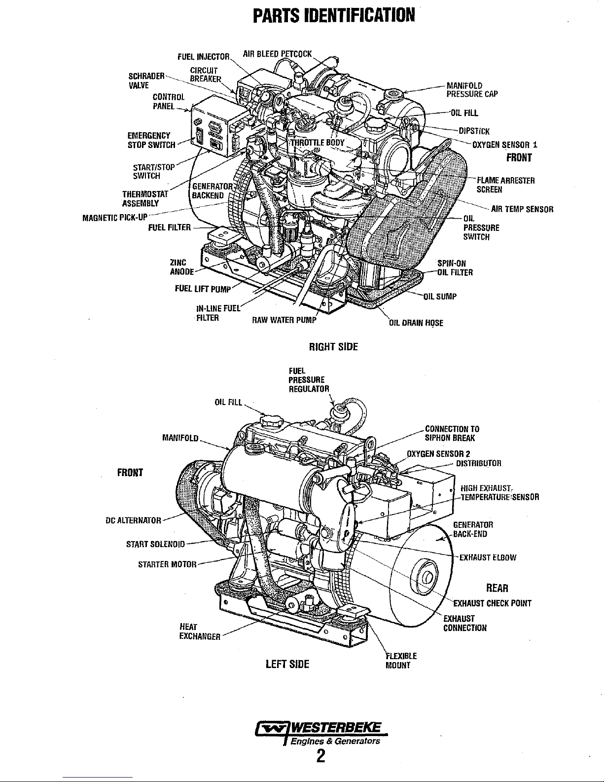
EMERGENCY
STOP
SWITCH
START/STOP
SWITCH
PARTS
IDENTIFICATION
-----
OX1rGEN
SENSOR
1
FRDNT
MAGNETIC
PICK-UP
FRDNT
ASSEMBLY
FUEL
FILTER
ZINC
ANODE
FUEL
-~~
LIFT
IN-LINE
FILTER
OIL
FUEL
FILL
RIGHT
FUEL
PRESSURE
REGULATOR
SIDE
AIR
TEMP
DRAIN
HgSE
SIPHON
BREAK
SENSOR
,--",:::::o,"<~
2
DISTRIBUTOR
HIGH
EXHAUST.
TEMPERATURE:SENSOR
SENSOR
DC
ALTERNAlroR-----
START
SOLENOID
STARTER
Mn,rnD
HEAT
.--
LEFT
SIDE
~
WESTERBEKE
Engines & Generators
2
MOUNT
GENERATOR
:--t-I'XHIIUST
ELBOW
REAR
'-.E:(HAI~ST
CONNECTION
CHECK
POINT
Page 13

INTRODUCTION
ORDERING
Whenever replacement parts are needed, always provide
generator
include a complete part description
part needed (see the separately furnished Parts Catalog).
insist
or generic parts are frequently not
cations
NOTES,
As
this
maintenance schedules,
tor,
critical information
CAUTIONS,
NOTE:
A
observed,
the
engine
A
followed,
NOTE:
by WESTERBEKE.
the
engine
SPARES
Certain spare parts will
your WESTERBEKE generator or engine
SUGGESTED SPARE PARTS).
as
proper
the
way.
spares
on-board inventory of
PARTS
and
engine
model
and
serial
numbers.
and
part number
upon
WESTERBEKE packaged parts because will fit
made
to
as
original
CAUTIONS
manual
An
operating procedure essemial
CAUTION:
WARNING:
A carbon nwnoxide warning decal has been provided
room.
AND
fuel
WESTERBEKE
and
accessories
equipment.
AND
WARNINGS
takes
you
through
and
will
and
WARNINGS.
Procedures,
can
result
in
the
or
generator.
Procedures,
can
result
in
personal
Affix this decal in a visable location in
the
operating procedures,
troubleshooting of your genera-
be
highlighted
An
explanation
to
which
if
damage
or
which
if
injury
ACCESSORIES
be
and
needed
oil
filter can
will
brochure
the
proper WESTERBEKE
to
Often
be
difficult
provide
to
assist
support
even
you
you
In
addition,
for
the
same specifi-
by
NOTES,
follows:
note.
not
strictly
destruction
not
properly
or
loss
of
life.
and
maintain
when
cruising (see
simple
items
to
obtain
along
with
a suggested
in
preparing
parts.
of
the
each
Also
such
an
PROTECTING
Care
at
the
have resulted
many
thousands of hours of dependable service.
manufacturer
installed
operated
YOUR
INVESTMENT
factory
in
and
during assembly
in
a WESTERBEKE generator capable of
cannol
control
the
vessel
or
the
manner
serviced
in
the
how
field.
or
This
and
where
in
which
is
thorough testing
However
the
generator
the
unit
up
to
the
buyer/owner-operator.
NOTE:
Six important steps
• Proper engine
•
An
efficient well-designed exhaust system that includes
anti·siphon break to prevent water
an
engine.
• Changing the engine oil
inghours.
• Proper maintenance
nents according
manual.
•
Use
clean,jiltered unleaded fuel.
• Wuzterize
Recommissioning" section in this manual.
and
your
ellgille according to the "Lay-up
UNDERSTANDING
The gasoline engine driving
ways
similar
to
a gasoline
are verticle in-line,
overhead camshaft
a solid-state distributor
camshaft-driven. The engine incorporates a pressure
lubrication system,
which
is
thermostatically-controlled.
generator's
that
important factors
ventilation,
cooling system
engine
is
required of a gasoline automobile engine.
which
requires
to
maintenance
and
/0
ensure long generator lite:
generator illStallatWll
from
am!
oil jilters every 100 operat-
of
all engine and generator compo-
to
the maintenance schedule
THE
GASOLINE
an
automobile
and
the
engine's cylinder head
is
chain-driven. The engine utilizes
which
is
and a fresh
the
the
generator
water-cooled engine
the
same
generator's longevity are proper
of
the
fuel
GENERATOR
AC
generator
engine.
horizontally
To
a large
preventive
system,
backend.
mounted
ignition
and
alignment.
entering the
in
is
in
many
The
cylinders
has
degree,
maintenance
The
the
is
is
this
and
an
and
type
block
the
most
system,
~
WESTERBEKE
Engines & Generators
4
Page 14

FUEL,
ENGINE
OIL
AND
ENGINE
COOLANT
GASOLINE
A
CAUTION:
rating
of
89
harm
to
your
Care
Of
The
Use
only clean
your
fuel
injection pump
particles which might pass through
finely
these
and
keep it clean. The best
unsatisfactory
facilities.
engine's daily
advisable:
Purchase a well-known brand of
Install
metal
and
ENGINE
Use
Change
break-in operation,
thereafter.An
for
To
and
regularly service a good, Coast Guard approved
bowl type filter/water separator between
the engine.
DlL
a heavy duty engine
the
this
engine
Only
use
unleaded
or
higher.
engine
Fuel
fuel!
finished
by
assure that
use
engine oil
oil
viscosity of
in
Leaded
and
fuel
violate
Supply
The clearance of
is
very
critical; invisible dirt
parts.
It
is
important
fuel
can
careless handling or improper storage
the
fuel
going into
is
clean
and
pure,
fuel.
oil
with
and
filter
after
and
every
100
SAE
all
conditions.
fuel
with
will
cause
your
warranty.
the
components
the
filter
to
be
rendered
the
the
following practice
an
API
classification of
an
initial
hours
of operation
15W-40
is
an
octane
serious
in
can
damage
buy
clean
fuel,
tank
for
your
the
fuel
tank
50
hours
recommended
of
SJ.
is
ENGINE
WESTERBEKE recommends a mixture of 50% antifreeze
50%
that
The
to
the
cooling circuit
antifreeze that contains supplemental cooling additives
that keep
lenn
The water
poured
NOTE:
antifreeze thot is now available.
A proper 50/50 mixture
engine coolant
COOLANT
A coolant recovery tank kit
The
coolant
without
the
COOLANT
distilled
can
antifreeze performs double
run
engine
protection.
purpose of this recovery tank
cooling system.
water.
Distilled water
corrode internal engine surfaces.
at
proper temperatures
to
the
coolant.
from
the
antifreeze chemically balanced, crucial
and
antifreeze should
into
the
cooling circuit.
Use the new environmentallyfriendly, long lasting,
to
temperatures of -40'P
RECOVERY
expansion
the
loss
of
rust
as
and
contraction
coolimt
It
also lubricates
and
recommended
TANK
is
and
is
free
from
duty.
It
allows
by
transferring heat away
and
corrosion.
supplied with each
without introducing
Use
a good quality
be
premixed before
will
is
to
allow
during
engine
protect
for engine
the
protects
the
chemicals
engine
from
the
(SCAs)
to
long
being
the
generator.
operation,
air
into
and
A
CAUTION:
engine
oil
additives
to
produce
00
to
mix.
Each
of
different
properties
not
allow
brand
brands
harmful
two
or
more
contains
could
react
to
your
brands
its
own
in
the
engine.
of
additives;
mixture
~
WESTERBEKE
Engines & Generators
5
Page 15

PREPARATIONS
PRESTARTINSPECTION
Before starting your generator
longed layoff,
• Check the engine
the
full
• Check the
bowls
• Check the
and battery cable connections.
• Check the coolant
and at
NOTE:
the engine:r cooling system will be purged
recovery tank. Open the
the cooling system is purged
after the engine
tank will be drawn into the engine:r cooling system
replace the purged
Before subsequent operation
manifold shauld be topped off,
tank may need to be filled to the
check the following
oil
mark
on
the
fuel
supply
for
contamimmts.
DC
electrical system. Inspect
level
the
manifold.
After the initial running
has
air.
for
the
first
time
items:
level:
add
oil
to
maintain
dipstick.
and
examine
in
both
air
cooled, the coolant from the recovery
the
fuel
wire
the plastic recovery tank
of
the generator, the air in
to
bleed petcock to ensure that
of
air.
After shutdown
of
the generator, the engine's
and
the coolant recovery
MAX
level.
FOR
or
after a pro-
the
level
at
filter/separator
connections
the coolant
GJUi
to
OIL
FILL
INITIAL
•
Visually
parts,
threaded
•
Check
the
• Examine the air
•
Be
the
•
Be
neutral
requires,
to
the
or
open
voltage
•
Make
A
recommended
motors,
up
to
This
unanticipated
prevent a cold
START-UP
examine
disconnected
connections. Search
load
leads
wiring
diagrams.
sure
no
other generator
load
lines.
sure
that
in
is
properly
and
that generator
load
neutral.
neutral
on
unbalanced
certain
the
CAUTION:
be
switched
speed
and,
precaution
operation
the
unit.
wires,
for
correct connections
inlet
and
outlet for
power systems
grounded
In single phase
can
supply
loads.
raw
water
When
starting
that
all
AC
loads,
OFF
until
in
cold
climates,
will
prevent
of
engine
from
Look
for
unattached
for
any
or
utility
with a neutral
(or
ungrounded)
neutral
systems
the
wrong
thru-hull
the
especially
the
engine
starts
damage
the
AC
machinery
stalling.
loose
or
missing
hoses,
and
gasoline
as
specified
air
flow
obstructions.
power
is
connected
line
as
is
properly
an
line-to-neutral
is
open.
generator,
large
has
come
to
warm
caused
by
and
check
leaks.
in
that
the
the
system
connected
incomplete
it
is
up.
will
to
AIR
BLEED
PETCOCK
Engines & Generators
6
Page 16

.
STARTING/STOPPING
PRO
GENERATOR
CONTROL
PANEL
AC
CIRCUIT
IrITii~~~
BREAKER
----+.Ii
HOURMETER
BA
FUSE---_W
EMERGENCY"
","_L
,
"00
5
'
START/STOP
o
SWITCH
--"""'
__
-""
p
m
Starting
Simply press
the
START switch
and
the
generator will start.
A green light will glow indicating the generator
is
running.
Stopping
To
stop-depress
the
STOP side of
the
start
switch,
the
green
light will
go
out
and
the
generator
is
stopped.
Failure
to
Start
The start cycle
will
automatically tenninate if
the
unit
fails
to
start after 12-14 seconds of cranking.
Wait
20
seconds,
then
repeat the start.
If
the
unit again
fails
to
start, investigate
the
cause.
Sometimes after servicing
the
fuel
system or changing
the
fuel
filter,
air can accumulate in
the
fuel
line or
the
throttle
body and prevent starting.
The
Schrader
valves
on
the
throttle body
and
the
fuel
cell
are
used
to
remove trapped
air.
This air
is
mixed
with
fuel
and
under high pressure. Follow
the
BLEEDING THE FUEL
SYSTEM instructions in
this
manual.
•
START----'STOP
o
REMOTE
CONTROL
PANEL
ECU
CONINECTIONS
~-~.-£'---EN["NE
HARNESS
CONNECTION
FIREBOY,
CO
DETECTOR
AND/OR
AUXILIARY
STOP
CONNECTION
REMOTE
START/STOP
PANEL
The
components on
the
panel
are:
1.
A three position start/stop rocker
switch.
2.
A green
LED
run indicator light on the rocker
switch.
3. A four position LED fault shut down display board.
The start/stop rocker switch functions
the
sarne
as
the
start/stop rocker switch
on
the generator's control
panel
as
previously explained.
The start/stop rocker switch indicator light on the rocker
switch
will
illuminate when the start circuit
is
energized.
It
will
go
dim
as
the engine cranks and will brighten
as
the
engine sttuts
to
indicate the generator is running.
The
LED
fault
shut down display board has four separate
LED
lights
to
display
to
the operator the cause of
the
generators
automatic shut
down.
The four
LED
displays
are:
low
oil
pressure, high engine operating temperature, high exhaust
temperature
and
engine over-speedlunder-speed
(flashes).
Should
the
generator shut down
from
one
of these
faults,
the
fault
LED
will remain illuminated.
To
reset
the
LED,
the
stop
switch
must
be
momentarily depressed.
This remote panel is a plug-in accessory and
is
available with a
15'
to
100' wiring harness .
~
WESTERBEKE
Engines & Generators
7
Page 17

BREAK-IN
PROCEDURE/DAILY
OPERATION
BREAK-IN
After the generator has been started, check for proper
operation and then encourage a fast wann-up. Run the
generator between
hours.
A
genllfBtor
After the first 10 hours
can be increased to the full-load rated output; then
cally vary the load.
Avoid overload at all times. An overload is signaled by a
smoky exhaust with reduced output voltage and frequency.
Monitor the current being drawn from the generator and keep
withinthe
it
at
1800 rpm to produce 60 hertz, control
engine break-in is governed by the current drawn from the
generator.
To protect against unintentional overloading
'.
the generator's output leads should be routed thmugh a
circuit breaker
generator.
NOTE:
current drawn required/or starting motors.
amperage drawn
amperage. See GENERATOR INFORMATION in this
manual.
PROCEDURE
20%
to
60%
of
full load for the first 10
CAUTION:
Be
aware
Do
not
attempt
by
running
generators' rating. Since the generator operates
thitt is rated at the rated output
without a load.
of
afmotor
can
be 3
the generators' operation, the load
starting loads and the high
to
to
break·in
of
5 times nonnal
the generator's
of
This
your
periodi-
the generator,
of
the
starting
running
NOTE:
Some unstable running may occur in a cold engine.
This
condition slwuld abate as nonnal operating temperature
is reached and loads are applied.
A
CAUTION:
periods
of
00
not
time
without a load
operate
the
generator
being
placed
for
on
long
the
generator.
STOPPING
Remove the major
Allow the generator to run for a few minutes to stabilize the
operating temperature and press the
CONTROL PANELS).
NOTE:
the maintenance schedule
GENERATOR
Once the generator has been placed in operation, there may
be governor adjustments required for engine speed (hertz)
during the engine's break-in period (first
this period (see
under ENGINE ADJUSTMENTS. A no-load voltage
adjustment may also be required in conjunction with the
engine's speed adjustment (see
INFORMATION).
A
THE
GENERATOR
AC
loads from the generator one at a time.
STOP switch down, (see
After the first
50
hours
for
of
generator operation check
the
50
hour service check.
ADJUSTMENTS
50
ENGINE SPEED (HER1Z) ADJUSTMENT
GENERATlOR
WARNING: . VENTILATION
hours) or after
CHECK
Follow this checklist each day before starting your generator.
• Record the hourmeter reading
• Visually inspect the engine for fuel, oil, or water leaks.
• Check the oil level (dipstick).
• Check the coolant level in the coolant recovery tank.
• Check your fuel supply.
• Check the starting batteries (weekly).
• Check the drive belt for wear and proper tension (weekly).
• Check for abnormal noise such as knocking, vibration and
•
LIST
in
your log (engine hours
relate to the maintenance schedule).
blow-back sounds.
Confmn
When the engine is cold - White
When the engine is
When the engine is overloaded - some Black
exhaust smoke:
wann
Smoke.
- almost Smokeless.
Smoke.
Gasoline vapors can explode. Before starting the engine,
operate the blower for at least four minutes and check both
the engine compartment and the bilge for gasoline vapors.
Run the blower below cruising speed.
Engines & Generators
8
Page 18

SAFETY
SHUTDOWN
SWITCHES
DESCRIPTION
The engine/generator is protected by switches and sensors
that send signals
to
the ECU that it interprets as a fault and
automatically shuts down the generator drive engine. When
an automatic shutdown occurs, one of the control panel fault
LED lights will illuminate indicating what fault caused the
engme to shutdown.
TIlls LED will stay illuminated.
To
correct the fault, refer
to
ENGINE TROUBLESHOOTING
in
this manual. Do
not
attempt
to restart
the
generator
before correctiog
the
fault.
WDISPlAY
PCBOARD
(INTERIOR
VIEW)
~I
CONTROL
PANEL
INDICATOR
LIGHTS
PRESSURE
FUSE
Four
LED
fault ligbts are located on the generator control
panel
and
the
remote start/stop panels. Should a problem
occur during generator operation the individual light will
indicate
Where
the problem
is
and at the same time shut the
generator down. The light
wjll continue
to
glow after the
generator shuts down.
Should this occur, refer
to
ENGINE
TROUBLESHOOTING in this manual.
OIL
GALLERY
OIL
PRESSURE
SENSOR
An oil pressure sensor (located just below the oil filter) sends
a
DC
Voltage to the ECU that it interprets
as
oil pressure.
Should
this
voltage faIl below a certain level, the ECU will
shut
the
generator down and illuminate the low oil pressure
LED.
Should
this occur, refer
to
ENGINE
TROUBLESHOOTING
in this manual.
EXHAUST
TEMPERATURE
SWITCH
A temperature switch is mounted on the exhaust elbow
to
monitor
the
temperature
of
the exhaust coolant and gasses.
Should
the
switch sense an excessive exhaust temperature,
the
ECU
will
shut the generator down and
the
exhaust
temperature LED will illuminate on the control panel.
Should
this
occur, refer
to
ENGINE TROUBLESHOOTING
in
this
manual.
COOLANT
SENSOR
THERMOSTAT
ASSEMBLY
COOLANT
TEMPERATURE
SENSOR
A coolant temperature sensor is located on the thennostat
housing
to
monitor the engines fresh water coolant. Should
the
coolant temperature reach
21O"F,
the ECU will shut the
generator down and the engine temperature LED will
illuminate.
Should this occur, refer
to
ENGINE
TROUBLESHOOTING in this manual.
OVERSPEED
SWITCH
An
overspeed high RPM shutdown sensor
in
the ECU will
shut the engine down if the engine
RPM"S exceed
the
set
limit and the LED will remain
lit.
If
an
underspeed problem
occurs, the engine
will
shutdown
and
the LED will remain
flashing.
DC
CIRCUIT
BREAKER
The generators engine
is
protected
by
a panel mounted man-
ual
reset circuit breaker (20 amp).
An
electrical overload
in
the
engine's wiring hamess or the instrument panel
will
trip
this
breaker
and
shutdown the engine/generator. If this should
occur, inspect and repair the problem. then reset the breaker
and
sestart
the
engine/generator.
Engin~s.
& Generators
9
Page 19

A
WARNING:
running.
use
serviCing
Wear
the
co"ect
any
I
SAFE
I Maintenance items that are very imponant to the proper operation
CD "Safe
MAINTENANCE
Never
the
tools
of
proper
the
engine's
CO"
attempt
for
generators.
safety
each
DC
to
perform
equipment
job.
Disconnect
electrical
SCHEDULE
any
such
equipment.
service
as
goggles
the
battery
while
and
terminals
the
engine
gloves,
when
is
and
of
SCHEDULED
MAINTENANCE
Fuel
Supply
Fuel/Water
Engine
Oil
Coolant
Level
Drive
Belts
Visual
Inspection
Sparts
Plugs
Starling
(and
Engine
Generalor
Fuel
Air
Exhausl
Engine
Raw
Heal
Cootanl
Fuel
Inlel
Banerles
House
011
un
Pump
Screen
Syslem
Hoses
Waler
Exchanger
Syslem
Filler
Fuel
Filler
Separator
Level
of
Engine
I~EI
Baneries)
FcHI
Pump
CHECK
EACH
DAY
0
0
0
0
0
weekly
0
0
weekly
HOURS
OF
OPERATION
100
50
NOTE:
will
inhibit
0
0 0
0
250
500
Keep
engine
the
surface
engine's
0
0
0
0 0
abifity
0 0 0 0 0 0
0
0
0
0
0 0 0
0 0 0 0
0 0 0
0 0
0
0
0 0
0 0
0
0
0
0
750
1000 1250
clean.
Dirt
to
remain
0 0
0
0 0
0
0
0
0 0
0
0
and
cool.
oif
0
0
0
0
Unleaded
Check
necessary).
Oil
dipstick.
Check
Add
Inspect
and
Check
electrical
for
Check
Every
and
excessive
Initial
change
Check
no
Periodically
are
Clean
Initial
Inspecl
Check
buildup
necessary.
Hose
become
Remove
Inspect
Lubricate
Clean
cap
for
Drain,
appropriate
Change
Change
gasoline
for
water
level
should
at
recovery
coolant
for
proper
adjust
if
for
fuel,
connections.
loose
belt
gap,
50
operating
make
sure
corrosion.
engine
both
that
AC
chafing-see
clean
and
at
50
check
for
leaks.
the
exhaust
on
inside
Check
should
spongy.
the
impeller,
impeller
or
replace
and
clean
professional
flush,
every
every
MAINTENANCE
with
and
indicate
tank;
if
needed.
tension
needed.
oil
and
tension.
inspect
connections
oil
and
every
100
connections
GENERATOR
inspect
tight.
hrs.,
then
at
50
hours,
Check
elbow
passages;
that
be
hard & tight.
Check
pump
cover
cam
when
anode.
oul
debris.
cleaning
and
refill
antifreeze
250
operating
250
operating
DESCRIPTION
octane
dirt
in
fuel
between
if
empty,
(3/8'
Check
belt
water
leaks.
Keep
bolts & nuts
for
burning
hours
check
are
filter
change
hours.
are
for
leaks,
every
100
Ihen
anti-siphon
for
carbon
clean
all
connections
and
tighten
and
and
wear
reassembling.
Open
Remove
and
COOling
mix.
hours.
hours.
INFORMATION.
electrical
Replace
inspect
pressure
rating
of
89
(drain/replace
MAX.
and
check
at
manifold.
to
1/2'
deflection)
edges
for
wear.
Inspect
tight.
and
corrosion.
electrolyte
very
tight.
Clean
at
50
hours,
clean
and
secure
connections
hours.
every
250
hours.
valve
operation.
and/or
and
replace
are
tight.
if
hoses
all
hose
for
wear.
plate.
Replace
heat
exchanger
every
1000
testing.
system
with
(continued)
of
higher
filter
if
LOW
on
wiring
and
Check
levels
off
then
with
corrosion
as
clamps.
gasket.
end
hours
Engines & Generators
10
Page 20

MAINTENANCE
NOTE:
Use the engine Murmeter gauge
engine hours by
running
time.
SCHEDULE
to
log your engine hours
or
record your
SCHEDULED
MAINTENANCE
"Starter
Distributor
"Engine
"Engine
"Exhaust
Catalyllc
"Exhaust
Catalyst
Oxygen
CO
Motor
~
Cylinder
CompreSSion
Valve
Clearances
Timing
Elbow
Converter
System
Pressure
.1mI
Sensor
In
Exhaust
and
Belt
~
Back
1"t1f1
CHECK
EACH
DAY
HOURS
OF
100
50
250
500
0
0 0
0 0
0
0
0
OPERATION
750
1000 1250
0
0
0
0
Check
0
and
lubricate.
pinion
Check
cap
and
Incorrect
performance,
timing
Remove
NOTE:
recommended
failure
Test
exhaust
casting
NOTE: A defective
carbon
Remove
inspect.
Perform
developing
above
operating
Remove
inspect
Inspect
Sample
MAINTENANCE
solenoid
drive.
ignition
and
resulting
1.5
and
Clean
timing.
rotor.
valve
clearance
check
adjust
and
replace
Failure
to
replace
interval
in
elbow
is
corroded
monoxide
water
injected
Replace
every
back
pressure
restrictions
PSI
or
41
amperage
water
injected
every
2000
every 1 000
with
CO
analyzer.
valve
major
exhaust
leakage!
DESCRIPTION
motor
for
corrosion.
and
lubricate
Check
condition
will
result
compression
clearances.
every
1000
the
timing
could
result
damage
for
casting
integrity.
or
deteriorated.
elbow
exhaust
2000
that
inches
load.
hours.
hours.
hours.
test
to
ensure
will
of
water
Correct
exhaust
Replace
Replace
elbow
increase
elbow
the
starter
of
in
poor
pressure
hours.
belt
at
in
timing
to
the
engine.
Replace
can
cause
and
system
column
as
needed.
and
as
needed.
every
Remove
motor
distributor
engine
and
the
chain
if
visually
is
not
pressure
at
full
visually
2000
hours.
·WESTERBEKE
recommends
this
service
EXHAUST
be
performed
MANIFOLD
by
an
authorized
ADJUSTABLE
CLAMP
.0~~"
Engines & Generators
mechanic.
11
Page 21

FUEL
SYSTEM
GASOLINE
Use unleaded 89 octane
follow
U.S Coats Guard regulations, close off all hatches and
companionways to prevent fumes from entering the boat, and
ventilate after fueling.
NOTE:
The generator compartment should hnve a gasoline
fume
detector/alarm properly installed
GASOLlNEJWATER
A primary fuel filter
type
must
be
installed between
and the engine to remove water and other
contaminant's from the fuel before they can
be carried to the fuel system on the engine.
Most installers include a type
separator with the installation package as
they are aware
contaminant's
These gasoline filters must have
(not
"see-through") to meet U.S. Coats Guard
requirements. The metal bowls have drain
valves to use when checking for water and
impurities.
of
in
the fuel can cause.
or
higher gasoline. When fueling,
SEPARATOR
of
the water separalting --,-,
th~
of
filter/water
the problems that
metal
and
working.
AND
bowls
WESTERBEKE
i
NUMBER
(49602)
__
PART
~\
ENGINE
Periodically check the fuel counections and the bowl for
leakage. Replace the filter element after the first
then follow the
Changing
1. Shut the fuel supply to the generator off.
2. Ensure there is no pressure in the fuel system by bleeding
S.
6.
7.
INLET
1. Shut off the fuel supply to the generator. Disconnect the
2. Thread
3.
FUEL
FILTER
50 hours
MAINTENANCE SCHEDULE.
Filter
Element
off any existing pressure using a Schrader valve on the
throttle body and fuel cell.
shown on the next page.
Unscrew the fuel bowl from the housing and allow the
bowl to come away from the housing.
Remove and replace the filter element and clean the
bowl.
Inspect both
Press on a new filter and replace the filter bowl.
Open the fuel supply. Inspect for leaks.
FUEL
fuel supply line to the inlet filter and unscrew the filter
from the pump inlet. Take care to catch any fuel that may
be
present.
fuel supply line.
tightening the fuel supply line so
inlet filter.
Tum
generator. Ensure that there are
"0"
rings. Replace
FILTER
on
the replacement inlet filter and connect the
Use care when connecting and
on the fuel supply to the generator and start the
Use a pressure testing kit as
if
necessary.
as
not to distort the
no
leaks.
FUEL
CELL
ENGINE
FUEL
FILTER
1~;::::;i1ir11
FUEL
PUMP
Periodically check the fuel counections
and make sure that no leakage is present and that the fittings
are tight and secure. The engine mounted fuel pump is
maintenance
free.
to
and out
FUEL
TO
..
<.CooLER
PUMP
of
the pump
FUEL
,.yo
WESTERBEKE
Engines & Generators
12
Page 22

FUEL
SYSTEM
BLEEDING
1. Insure that the fuel cell is
harness, and that the lift pump
2. Attach
pressure gauge set
A
safe
THE
FUEL
Snap On MT337B, OTC
to
CAUTION:
use
of
the
Follow
gauge
SYSTEM
not
connected
is connected.
nIl
the Schrader valve on fuel cell.
manufacturer's
SlIts
to
purge a high·pressure
to
the
wiring
or equivalent
instructions
fuel
for
fuel
system.
3. While holding the stop switch
position, purge the air from the fuel cell. The fuel cell
purged when no air bubbles are visible escaping from the
drain line attached to the Schrader valve.
typically be
4. Remove the pressure gauge set from the fuel cell and
connect it
5. Connect the fuel cell
Open the valve on the fuel pressure gauge purge line. Do
6.
not prime the system without the fuel gauge purge valve
or
open
happens, repeat steps I,
air from the fuel cell.
7. Repeat step 3, this time purging the air completely from
the
throttle
. throttle body after purging the system.
IoTE:
purged.
visible in the purge line. .
3-4 psi.
to
the Schrader valve on the throttle
to
the wiring harness.
air can be forced back into the fuel cell.
2,
body.
The pressure should be 40 psi in the
The
system
can develop
The
system
is
fully
in
the (prime) depressed
Pressure should
body.
If
this
and 3
to
remove the trapped
40
psi
without being
purged when no bubbles are
fully
is
TO
"SNAP-ONEXCELLENT
FOR
BLEEDING
8.
Remove the pressure gauge set, and cap all Schrader
valves.
9.
Insure that all wire connections are secure and that there
are
no
leaks in the fuel system.
A
fuel that
dispose
TOOL"
PROVIDES
PRESSURE
PRESSURE
WARNING:
TESTING
SCHRADER
may
be spilled
of
the , __
Take
,
-".!r-----
GAUGE
AND
TEST
care
'.11.'
AN
KIT
PORTS
to
and
properly
catch
.".,
any
COOLER
KIT
ADAPTER
INCOMING
VALVE.
FUEL
CELL
FUEL
..t:~+--+---
\\j':_+-tL---INLET
FILTER
FUEL
FUEL
PUMP
FILTER
12A
Page 23

ELECTRONIC
FUEL
"«'UL'''U''\.
STEPPER
THROTTLE
ASSEMBLY
MOTOR
AND
SHAft
THRonLE
The above illustration shows tl,e throttle body assembly that
attaches to the intake manifold.
An electronic control unit (ECU) controls the fuel injector
and the stepper motor.
The
sensors
temperature, map sensor (intake manifold absolute pressure),
engine rpm and battery voltage.
The
appropriate injector pulse rate and throttle opening position.
A high pressure fuel pump supplies fuel to the area around
the injector and the regulator maintains the fuel pressure in
that area at 35 -
The injector is a solenoid operated pintle valve that meters
fuel into the intake manifold depending on engine operating
conditions and generator amperage load determined by the
ECV.
Air flow into the intake manifold is controlled by the
operation
plate positioning for proper air flow
accomplished through the
operating conditions. The Schrader valve is used to
monitor/check fuel pressure around the fuel injector.
ELECTRONIC
The
and requires no adjustments by the generator operator.
controls all starting, operating and safety shutdown features
on the engine. The Gain Pot is set at #50 midpoint for
optimum
Dipswitch
ON is for
remaining switches #2, 3#. and
BODY
AIR
TEMPERATURE
SENSOR
ECV
is supplied with engine operating conditions from
that
monitor
ECV
interprets this information to determine the
of
the throttle plate via the stepper motor. Throttle
ECV
(Electronic Control Vnit) is factory programmed
system
#1
50
intake
air
temperature,
40
PSI maximum.
mto the engme is
ECV interpretation
CONTROL
response.
is used to charge the generators frequency.
hertz and OFF is for 60 hertz operation. The
UNIT
(ECU)
#4 service no functions.
LOWER
BODY
engine
of
UPPER
THROTTLE
coolant
engine
FUEL
THROTTLE
ECV
It
PROGRAM
INJECTION
NOTE:
When changing the generator frequency. turn OFF
the
DC
20
amp breaker before moving the dipswich.
The vacant program connector is used by the factory to input
the operating program into the
used
with
purchased
Safe
CO
systems.
The electrical connections from the engine electrical harness
are made to the
pin and one 35 pin and may therefore vary in number
according to the generator model. For further details. consult
the
engine
circuit
The ECV is normally set for operation at 60Hz unless
specified otherwise, and is internally configured for a 4 pole
generator.
is configured by label for the generator in use.
ECU
Stability
When changing engine speed.
condition should occur, the gain pot may require adjustment.
There is no specific set point for this adjustment and it is
normally set to the middle
range which obtains optimal engine speed response without
any tendency
Setting
The engine speed can be set for operation at either 50 or 60
Hz. Corresponding engine speeds for a 4 pole generator are
1500 rpm
1.
2.
3. Adjust the GAIN setting between
NOTE:
operation. In such cases, lessen the
Replacing
Remove
the ECU, turn
Unplug the two engine harness connections. Then unscrew
the four side screws securing the ECU and remove it from
it's holder. To install a new
If
it is necessary
ADJUSTMENTS
Trim
Engine
or
1800 rpm.
Set
up whatever equipment is to
engine speed
Start up and run the generator at the current operating
speed and frequency. .
reaction
to
A higher GAIN adjustment can induce unstable engine
the
the
control
software
ECV
through two plug connections, one 23
wiring
(Gain)
of
hunting.
Speed
or
generator output frequency.
AC
amperage load changes.
ECU
box
OFF
the 20 amp
ECU
ECV. This connector can be
to
monitor
diagram
to
replace the ECV, make sure it
or
if
of
its range
cover.
Before
DC
ECU, reverse the procedure.
the
operation
in
this
manual.
no engine hunting
or
to a point in its
be
used
to
measure
40
- 60 for best system
GAIN
adjustment.
attempting
control panel breaker.
to
remove
of
the
-..v-
WESTERBEKE
Engines & Generators
128
ADJUSTMENT
POT
Page 24

COOLING
SYSTEM
FRESH
NOTE:
recommended antifreeze
. fresh water coolant.
Fresh water coolant is pumped through the engine by a
circulating pump, absOIbing heat from the engine. The
coolant then passes through the thermostat into the heat
exchanger where it is cooled, and returned to the engine
block via the suction side
engine is started cold, external coolant flow is prevented by
the closed thermostat (although some coolant flow is
bypassed around the thermostat to prevent the exhaust
manifold from overheating). As the engine "'arms up, the
thermostat gradually opens, allowing full flow
coolant to flow unrestricted to the external pOItion
cooling system.
Coolant
A coolant recovery tank allows for engine coolant expansion
and contraction during engine operation, without any significant loss
ing system. This
engine manifold level and should be easily accessible.
WATER
Refer
Recovery
of
COOLING
to
the
ENGINE
CIRCUIT
COOIANT
and water mixture to be used as the
of
the circulating pump. When the
section
for
of
Tank
coolant and without introducing air into the cool-
tank should be located at or above the
the
the engine's
of
the
COOLANT
TANK
NOTE:
Periodically check the condition
sure cap. Ensure that the
good coTutition
closes tightly. Carry a spare cap.
and
upper
check that the vacuwn valve .opens
of
the manifold pres-
alld
lower rubber seals are in
and
CHANGING
The engine's coolant must be changed according to the
MAINTENANCE SCHEDULE.
become contaminated, it can lead to overheating problems .
A
critical; a substantial
traced
Drain the engine coolant by removing the drain plug on the
engine block and opening the manifold pressure cap. Flush
the system with fresh water, then reinstall the drain and start
the refill process.
NOTE:
be
used
A
Wear
Refilling
After replacing the engine block drain plug, close the heat
exchanger's coolant petcock. Slowly pour clean, premixed
antifreeze coolant into the water jacketed exhaust manifold
filler neck opening. Fill the system full, then start the engine.
Monitor the coolant in the manifold and add as needed. Fill
the manifold
pressure
Remove the cap on the coolant recovery tank and
coolant mix
the cap. Run the engine and observe the coolant expansion
flow into the recovery tank.
After checking for leaks, stop the engine and allow it to cool.
Coolant should draw back into the cooling system
engine cools down. Add coolant
needed and check the coolant in the manifold. Clean up any
spilled coolant.
COOLANT
If
the coolant is allowed to
CAUTION:
back
The drain petcock on the heat exchanger should also
to help drain engine coolant.
WARNING:
protective
the
cap.
Proper
to
cooling
cooling
number
system
Beware
of
the
system
of
maintenance
engine
corrosion.
hot
engine
fai/ures
gloves.
Coolant
to
the filler neck and install the manifold
to
halfway between
LOW
and
MAX
to
the recovery tank
can
coolant.
fill
with
and replace
as
the
if
is
be
SEAL
MANIFOLO
PRESSURE
CAP
-.y-
WESTERBEKE
Engines & Generators
13
COOLANT
EXPANSION
KEEP
THESE
A
FULL
FLOW
THE
COOLANT
CLEANER
PASSAGES
OF
COOLANT
RECOVERY
WORKS
WELL)
CLEAR
TO
ANO
TANK
TO
ENSURE
FROM
( A
PIPE
Page 25

HEAT
EXCHANGER
Cool
raw
water
flows
through
exchanger.
the
which
The
and
The
this
deposits
Heat
After approximately
and
motive radiator shop should
exchanger.)
NOTE:
that a heat exchanger cleaning be
every
As
the
engine
heat
of
the
internal
is
then
pumped
engine
coolant
(now
the
circuit
repeats
engine
coolant
and
keeps
the
engine's
found
in
raw
water.
Exchanger
pressure
Operating in silty andIor tropical waters
1000 hours.
ZINC
HEAT
EXCHANGER
Service
test
the engine's heat exchanger.
ANODE
---+\i'"tj
the
inner
coolant
passes
engine
is
conducted
into
the
exhaust
cooled)
itself
raw
water
1000
flows
water
are
passages
hours of operation,
be
able
tubes
of
around
to
tlJe
system
and
back
through
independent
clean
from
to
clean
peljormed
COOLING
the
heat
these
tubes
raw
water
discharged.
the
engine
of
each
other,
the
hannful
remove,
(A
and
mare often than
local
test
may
clean
auto-
the
heat
require
SYSTEM
If
the
zinc
anodes
need
replacement,
into
which
the
zinc
anode
is
threaded
loosening
hex
zinc
flakes
exchanger
have
one
Replace
exchanger end gasket part
install a new
NOTE:
do
may insulate the zinc from the metal
housing preventing electrolysis action
THERMOSTAT
A
thermostat,
engine,
continuously
the
coolant
hole
overheating).
gradually
checked,
and
the
anode
with
another
boss
from
possibly tearing off
is
in
poor condition,
within
the
exchanger.
and
clean
a spare heat exchanger end gasket
becomes
not require sealant. Sealant should
engine
in
gasket.
damaged
the
gasket (refer
zinc
The threads
located
controls
from
the
the
flows
is
first
flowing
thermostat
As
opens.
cleaned,
the
The
anode.
started,
or
there
are
Remove
the
inside of
when
removing
to
your engine model's heat
number),
of
the zinc anodes are pipe threads
near
the
manifold
coolant temperature
through
the
the
(some
coolant
to
prevent
engine
warms
thermostat
replaced
closed cooling
closed
the
is
easily.
hold
the
hex
with a wrench
wrench.
the
all
up,
accessible
This prevents
exchanger
probably a
the
end
zinc
in
the
O-ring
not
of
the heat exchanger
on
the
at
as
thermostat prevents
is
by-passed
exhaust
the
Carry
shell.
lot
of
of
the
debris.
Always
case
the
end
cover.
and
cover,
be
used as it
zinc.
the
front
the
coolant
circuit.
through
manifold
thermostat
and
can
a spare
thermostat
boss
while
zinc
heat
present
and
and
of
the
When
from
be
If
the
the
a
CLEAR
OUT
ZINC
DEBRIS
ZINC
ANODE
A
zinc
anode,
or
pencil,
is
located
circuit
witlrin
the
heat exchanger. The purpose of having
zinc
anodes
is
to
sacrifice
place
in
the
raw
water cooling circuit, thereby reducing
effects
of electrolysis
The condition of
and
the
anode cleaned or replaced
be
should
NOTE:
Electrolysis action is the result
installation and vessel location; not that
NEW
carried
,REPLACE
the
on
ZINC
them
on
other components of
zinc anode should
board.
ANODES
in
the
to
electrolysis
as
required. Spare anodes
of
WATER
DRAIN
raw
water
cooling
action
taking
the
system.
be
checked
each particular
oftJre
monthly
engine.
CLEAN & REUSE
Replacing
To
avoid
spilling coolant,
manifold
Remove
housing
gasket,
gasket before pressing
cap
engine
--..;-~
.'"
the
Engines & Generators
apply a thin
screws.
and
leaks
level
the
as
at
the
Thermostat
drain
the
coolant
(REFER TO CHANGING
cap
screws
and
disassemble
shown.
When
installing
coat of sealant
it
into
Replace
check for normal temperatures
the
the
coolant
tllermostat
GASKET
APPLY
SEALANT
ATASSEMBLY
housing.
place.
in
the
new
on
both
Do
not over-tighten
the
manifold.
THERMOSTAT
ASSEMBLY
down
below
COOlAN7).
the
thennostat
thermostat
sides
of
the
Run
and
that
there
the
and
the
the
are
14
Page 26

,
RAW
WATER
The
raw
non-ferrous housing
flexible blades
the impeller housing, producing
account
lubricant
impeller
Raw water pump impeller
water)
is
are
not
warrantable,
raw water
has a limited lifetime
NOTE:
Should a failure occur with the pump ~ internal parts
(seals
and bearings), it
a
new
pump
Inspectlng/Changing
Close the
and,
with
impeller out of the
a
pair
of
care.
not to tear the impeller). Install the
();.ring.
and push
assembling, apply a thin coating of lubricant
'and gasket.
Run
check for water discharge
dow indicates
Move the blades to conform
the
engine
PUMP
water pump
should this
for
the
and
impeller cover gasket
not present during engine operation. Such failures
flow
and
raw
the proper size impeller
screwdrivers
the
impeller into the
Open the raw water intake valve.
is
a self-priming, rotary pump
and
a neoprene
which
wipe against a curved cam plate
pump
be
impeller. There should always be a spare
failures
and
operators
is
present
rebuild the original pump as a spare.
water intake
and
the
pump
at
start-up. The neoprene impeller
and
must
may
be more cost effective
the
Raw
valve.
pump
(the impeller can be pried out
if
an
impeller puller
check for leaks around
at
the
has
not
impeller.
the
pumping action.
run
dry as water acts as a
(an
impeller
occur
when
are
cautioned
be
inspected regularly.
Water
Remove
tool,
pumps
stern
primed itself
Pump
the
carefully
is
new
to
the
curved
housing.
the
tube.
Absence of water
COOLING
with
a
The impeller
kit)
lubricant
to
make sure
to
Impeller
pump
pry
unavailable.
impeller
carn
When
to
the
impeller
pump.
properly.
within
On
no
aboard.
(raw
purchase
cover
the
using
Take
and
plate
Also
has
SYSTEM
RAW
WATER
NOTE:
Always install the strainer at
the strainer will always be self-priming.
A clean
engine's cooling
strainer
in
the glass
Perform
operation:
1.
Close the raw water seacock.
2.
Remove
3.
Clean
4.
Replace
5.
Reassemble
6.
Open the seacock.
7.
Run
NOTE:
Also follow the above procedure after having run hard
aground.
If
the
engine temperature gauge ever
normal
may
raw
reading,
have
water
INTAKE
raw
water intake strainer
system.
when
should
the
following
and
the
the
the
engine
been
through
making
glass.
your periodic engine
be
clear.
clean
sealing
and
install
and
the
cause
caught
the
STRAINER
is a vital
Include a
maintenance after every
the
strainer
washer if
check
may
up
in
cooling
the
the
necessary.
strainer.
for
leaks.
be
strainer,
system.
or
below the waterline so
component of
visual
inspection of
check.
100
filter.
shows
a higher
that
sil~
leaves
or
slowing
WASHER
the
The
hours
than
grass
this
water
flow
the
of
of
THE
PIN
SLOT
NOTE:
Never allow the
of
dry rnnning may destroy the impeller.
INSPECT
.
ANO
IF
OF
FITS
IN
THE
THE
IMPELLER.
THEY
SHOW
WEAR.
INTO
THE
SHAFT.
A
CAUTION:
impeller,
the
cooling circuit.
a-RING
REPLACE
SIGNS
____
they
-----...
LIGHTLY
PUMP
ANO
.
GLYCERIN.
If
any
must
be
They
pump
to ron dry. Even a short period
IMI'EL!ER
GREASE
CHAMBER,
IMPELLER
of
the
located
often
exchanger
THE
a-RING,
WITH
blades
to
prevent
can
.
have
be
.
broken
blockage
found
in
the
off
heat
in
the
FILTER
TYPICAL
DRAINING
When
can
be
plate
pump
Open
allow the raw water
THE
RAW
freezing temperatures
drained
screws.
and
the
by
This
also
drain
raw
water petcocklplug
WATER
loosening
should
allow
back
to
to
drain.
RAW
WATER
((]wner
COOLING
are
expected,
the
raw
the
the
strainer.
on
INTAKE
STRAINER
Installed)
SYSTEM
the
cooling system
water pump's cover
water
to
drain out of
the
heat
exchanger
the
to
Engines & Generators
15
Page 27

ENGINE
OIL
GRADE
Use a heavy duty engine oil with an API classification
Change the engine oil after an initial 50 hours
operation, and every
recommended oil viscosity, see the following chart:
OperatIng
Above
68' F (20'
41' -
68' F (5'_20'
Below
41' F (5'
A
CAUTION:
engine
tires:
mixture
CHANGING
The engine oil should be warm. Remove the oil drain hose
from its attachment bracket and lower it into a container and
allow the oil to drain,
hose and pump the old oil out. Make sure the oil drain hose
is properly secured in its holder after all
been drained.
Always observe the old oil as it is removed. A yellow/gray
emulsion indicates the presence
this condition is rare, it does require prompt attention to
prevent serious damage. Call a competent mechanic if water
is present
result
and/or.a siphoning through the water cooling circuit into the
exhaust, filling into the engine.
ail
til
additives
ta
produce
THE
in the oil. Raw water present in the oil can be the
of
a fault in the exhaust system attached to the engine
100 hours
Temperature
C)
C)
C)
Da
nat
mix.
Each
brand
af
different
properties
ENGINE
or
attach a pump to the end
of
operation thereafter. For
SAE
30,
SAE
allaw
twa
cantains
brands
cauld
harmful
OIL
of
water in the oil. Although
of
011
ViscDsity
10W-30
20
or
SAE
10W-30
aT
maTe
its
awn
react
ta
,auT
of
the old oil has
10W-30
brands
LUBRICATING
of
S1.
break-in
or
15W-40
al
addi·
in
the
engine.
of
the drain
OIL
Replacing
When removing the used oil filter, you may find it helpful
punch a hole in the upper and lower portion
to
drain the oil into a container before removing
to lessen spillage. An automotive filter wrench should be
helpful in removing the old oil filter.
and a plastic bag around the filter when unscrewing it to catch
any oil that's in the filter. Inspect the old oil filter
removed
off with the old oil filter.
sealed against the oil filter adapter, gently remove it. When
installing the new oil filter element, wipe the filter gasket's
sealing surface on the oil filter adapter free
thin coat
the oil filter.
and tighten the filter finnly by hand.
NOTE:
are
not
REFILLING
Add fresh oil through the valve cover. After refilling the oil,
run the engine for a few moments while checking the engine's
oil pressure. Make sure there is no leakage around the new
oil filter
engine. Then check the quantity
dipstick. Fill
';~'(llrllllll(';~
the
Oil
Filler
to
of
the old filter
it.
This helps
Place some paper towels
as
it is
to
make sure that the rubber sealing gasket comes
If
this rubber sealing gasket remains
of
oil and apply a
of
clean engine oil to the rubber sealing gasket on
Screw the filter onto the threaded oil filter stub,
Use genuine WESTERBEKE oil filters. Generic filters
recommended.
THE
OIL
SUMP
or
from the oil drain system, and then stop the
of
oil with the lube oil
t~\ou
FULL
mark on the dipstick.
\~~~~
OIL
DRAIN
WARM
THE
ENGINE.
THE
OIL
INTO
SUITABLE
.
CONTAINER
A
SHUTDOWN
AND
11~i.1;@~
DRAIN
!®_-
--<---11
SOCKET
1/4"
FOR
AN
"""
OIL
The
by the oil'pressure gauge on the instrument Ranel. During
normal operation, the
/16
"
60 psi (2.8 and 4.2 kg/em').
NDTE:
NPT
ADDING
EXTENSION
reading up
an oil pressure reading as low as
readings will vary depending upon the temperature
engine and the rpms. Refer to ENGINE ADJUSTMENT
pages
WESTERBEKE
Engines & Generators
16
SPIN·ON
OIL
FILTER
CHANGING
OIL
FILTER
PRESSURE
engine's
oil
pressure,
A newly started. cold engine can have an oil pressure
to
60
psi (4.2 kg/em". A
for
TESTING OIL PRESSURE.
during
operation.
oil pressure will range between
wanned
35
is
indicated
engine can have
psi
(2.5 kg/em". These
of
40
the
and
Page 28

INSTALLATION
This popular
filter
from
an
engine
NOTE:
instructions
APPLY A THIN
INSTAUING
TIGHTEN
CONTACTS
accessOIY
the
engine
room
bulkhead.
is
to a more
Refer to ENGINE OIL CHANGE
on
removing the oil
COAT
OF
CLEAN
THREAD
3/4
TURN
OIL
THE
THIS
KIT_
AN
ADDITIONAL
THE
BASE.
used
TO
THE
KIT
AFTER
REMOTE
to
relocate
convenient
filter.
O-RING
ON,
THEN
THE
in
WHEN
HAND
O-RING
the
location
this manual for
engine's
such
OIL
FILTER
oil
as
(OPTIONAL)
To
install,
simply
remove
WESTERBEKE's
install
this
kit
Contact your
NOTE:
Westerbeke
incorrect installation
A
CAUTION:
rectly.
If
the
pass
valve
from
reaching
failure.
If
immediately
remote
with
the
oil
WESTERBEKE
is
not
of
the
It
is
vital
oil
flows
in
the
filter
the
engine
there
is
no
oil
and
check
the
engine
oil
filter
oil
filter kit
filter
dealer
facing
as
down
for
shown.
as
mare
responsible for engine
Remote
in
the
assembly
causing
pressure
the
to
install
reverse
hose
Oil
Filte1:
the
oil
direction,
will
prevent
an
internal
reading,
connections.
FASTEN
SECURElY
and
thread
Always
illustrated.
information
failure
due
lines
cor-
the
by-
the
oil
engine
shutdown
TO A BULKHEAD
SUPPLIED)
on
to
NOTE
THE
ON
THE
ADAPTER
REMOVED
WILL
BE
RECONNECTED
"IN"
"OUT"
WHEN
FOR
INSTALLATION
MARKINGS
THE
HOSES
ARE
SO
THEY
CORRECTLY
THE
IN
CONNECTION
MUsT
ATTACH
CONNECTION
THE
OUT
MUST
ATTACH
CONNECTION
REMOTE
OIL
AT
FIlTER.
TO
THE
AT
THE
FILTER.
I
TO
THE
THE
HOSE
OUT
HOSE
IN
APPLY A THIN
GASKET
WHEN
CONTAC1S
3/4
THE
TURN.
COAT
OF
INSTALliNG.
BASE,
TIGHTEN
OIL
TO
AFTER
IT
AN
THE
FILTER
THE
FILTER
ADDITIONAL
.
Engines & Generators
17
Page 29

PUSH
ON
SPAOE
CONNECTION
MAP
SENSOR
SCHRADER
VALVE
THROTTLE
FUEL
INJECTOR
BODY
FUEL
PRESSURE
ASSEMBLY
AIR
TEMPERATURE
SENSOR
FROM
THE
THERMOSTAT
ASSEMBLY
i'
..
DESCRIPTION
The
above illustration shows the throttle body assembly
to
attached
An electronic control unit (ECU) controls the fuel injector
and the throttle actuator.
The
sensors
temperature, map sensor (intake manifold absolute pressure),
engine
The
appropriate injector pulse rate and throttle opening position.
A high pressure fuel pump supplies fuel
the injector and the regulator maintains the fuel pressure
that
area
the intake manifold.
ECU
is supplied with engine operating conditions from
that
monitor
rpm and battery voltage.
ECU
interprets this information
at 35 -
40
intake
PSI.
air
temperature,
engine
to
determine the
to the area around
coolant
RETURN
in
MANIFOLD
The injector
fuel into the intake manifold depending on engine operating
conditions and generator amperage load as
ECU.
Air flow into the intake manifold is through the flame
arrester/air filter and is controlled by the
the throttle plate via the actuator. Throttle plate positioning
for proper air flow into the engine
the
ECU interpretation
Schrader valve
the fuel injector and to bleed air from that area after fuel
is
a solenoid operated pintle valve that meters
deteimined by the
ECU operation
is
accomplished through
of
engine operating conditions. The
is
used to monitor/check fuel pressure around
of
system servicing.
An air intake heater
incoming air during a cold start.
is
positioned in the intake to heat the
Engines. & Generators
18
Page 30

ENGINE
ADJUSTMENTS
SPARK
The spark plugs should
first
thereafter and replaced as needed.
SPARK
SPARK
NOTE:
the spark plugs will retard corrosion, making future removal
of
INSPECT
PLUGS
be
cleaned and regapped after the
50
hour break-in period, then inspected every 250 hours
A
WARNING:
the
engine
removing
PLUG
GAP:
PLUG
TORQUE:
Loctite Anti-Seize applied to the threaded portion
the spark plugs easier.
FOR
00
is
hot.
them.
0.031 ± 0.002
25
DAMAGE
----..-
not
Allow
Nm.
remove
the
engine
in.
(0.8 -0.05
(18.45
«-Ib)
the
spark
plugs
to
cool
before
mm).
INSPECTING
THE
while
of
SPARK
PLUGS
CHECK
FOR
Vl'BUILD
UP
CARBON
AND
BURNING
DRIVE
The drive belts must be properly tensioned. Excessive drive
belt tension can cause rapid wear
service life
the presence
resulting in high operating temperatures.
This generator has two drive belts, one drives the governor
and alternator and the other drives the raw water pump. The
tension adjustment procedure for both belts is as follows:
1. Remove the belt guard.
2.
3. With the belt(s) loose, inspect for wear, cracks and frayed
4.
5. The drive belts are properly adjusted
BELT
ADJUSTMENT
of
the belts and reduce the
of
the fresh water pump's bearing A slack belt or
of
oil on the belt can cause belt slipping,
To
adjust the governor/alternator drive, loosen the two
governor mounting bolts.
To
adjust the raw water pump/fresh water pump drive
belt, loosen the two raw water pump mounting bolts.
edges and replace
To
loosen or tighten the alternator drive belt, slide the
alternator in or out
bolts.
To loosen or tighten the raw water pump/fresh water
pump drive belt, slide the raw water pump
required, then retighten its mounting bolts.
no less than 3/8 inch
(12mm) as the belt is depressed with the thumb at the
midpoint between the two pulleys
the belt.
if
necessary.
as
required, then retighten its mounting
in
or out as
if
it can be deflected
(lOmm) and no more than
on
the longest span
112
inch
of
..:
t
GAP
f
HIGH
TENSION
Check the ignition wires every 500 operating hours as engine
compartment heat can deteriorate the wires.
Check the resistance
because the wire connection inside the cap may become
separated
the wires from the spark plugs, grasp and twist the molded
cap, then pull the cap off the spark plug.
The
or
resistance
CORDS
the insulator may
valne
(IGNITION
of
each wire. Do not pull on the wire
is
410
WIRES)
be
damaged. When removing
ohm
per
inch
of
wire.
CHECKING
RESISTANCE
A
WARNING:
drive
belt's
6. Operate the engine for about 5 minutes, then shut down
the engine and recheck the belts tension.
Replace the belt guard.
7.
Never
tension
attempt
while
the
to
check
engine
or
is
in
operation.
adjust
a
Engines & Generators
19
Page 31

ENGINE
NOTE:
WESTERBEKE recommends that the following engine adjust-
ments
be
peifonned
below is provided to assist the mechanic.
ADJUSTMENTS
by a competent engine mechanic. The information
ENGINE
1. To check the engine's compression pressure,
2. Remove the spark plugs and install a compression
3. Close
4. Crank the engine with the start motor and unplug the
S. Measure the compression pressure for all the cylinders.
6.
7. Re-install plugs and ignition wires.
8.
COMPRESSION
engine then shut it down.
adapter (screws into a plug hole) with a gauge.
off
the raw water intake seacock.
ignition coil and allow the compression gauge to reach a
maximum reading and record.
Ensure that compression pressure differential for each
is
cylinder
Compression
If
a cylinder's compression or pressure differential is
below the limit, add a small amount
the spark plug hole and repeat steps 3 and 4.
a)
If
piston ring and/or cylinder wall may be worn or
damaged.
b)
If
pressure, suspect poor valve contact, valve seizure,
or
within the specified limit.
pressure
addition
additional oil does not increase compression
valve wear.
of
oil causes an increase
should
TEST
not
differ
bV
more
than
of
engine oil through
of
pressure, the
wann
14
psi
up the
(100Kpa).
Open the raw water seacock (thrn-hull).
IGNITION
TIMING
CRANKSHAFT
PULLEY
2. Start the engine and warm the engine to its nonnal
operating temperature.
3.
Using the timing light, align the timing groove in the
front crankshaft pulley with the proper timing
the ignition timing scale embossed on the engine's front
cover. Do this by loosening and slowly rotating the
distributor body. refer to the timing specification:
IGNmON
15·
BToC
(33· -35·
TIMING
± 1·
STATIC
AT
NO-LOAD
OIL
PRESSURE
AT
1800
(NO
WITH
RPM:
VACUUM
ADVANCE)
VACUUM
TESTING
GAUGE
ADVANCE)
OIL
PRESSURE
f)
~
mad<:
))
OIL
on
GALLERY
DIAL
GAUGE
MEASURING
COMPRESSION
IGNITION
1. Attach a timing light to the # I spark plug and mark the
TIMING
front crankshaft timing groove and the timing mark on
the scale embossed on the engine's front cover.
Each timing mark represents 5·.
"'"
WESTERBEKE
Engines & Generators
OIL:
PRE,SSU,RE
LOW
OIL
PRESSURE
The
specified safe minimum oil pressure is 4.3 - 1.4 psi(O.3 -
0.1 kg/em". An oil pressure
down. A gradual loss
bearings. For additional infonnation
ings, see the ENGINE TROUBLESHOOTING chart.
TESTING
To test oil pressure, remove the oil gallery
mechanical oil pressure gauge
the engine, read the oil pressure gauge.
OIL
PRESSURE
SENooR
AND
OIL
PRESSURE
35.0
(depending
SWITCH
TORQUE 9 -13
of
5 PSI will shut the engine
of
oil pressure usually indicates worn
on
low oil pressure read-
"T'
and install a
in
its place. After warming up
IbM
(3.8
kg/em')
or
more
at
1800
rpm
on
temperature
H-Ib
and
(1.2
load)
-1.8
m-kg)
20
Page 32

ENGINE
NOTE:
WESTERBEKE recommends that the following engine
adjustments be
The infonnation below is provided to assist the mechanic.
peiformed
ADJUSTMENTS
by
a competent engine mechanic.
TIMING
BELT
A
CAUTION:
reduces
belt
sprocket
These
parts
ously
contaminated
these
parts,
and
crankshaft
1
UPPER
INSPECTION
Water
the
service
should
check
COVER
and
tensioner
never
the
oil
seals
----..,..1.
life of
with
or
oil
be
dirt
front
for a
5
BELT
AND
REPLACEMENT
on
the
timing
the
belt.
Keep
the
free
of oil
and
cleaned.
or
case,
possible
TENSIONER
oil.
If
oil
7
SPROCKET
Replace
oil
is
pump
leak.
belt
severly
timing
greese.
if
seri-
evident
oil
seals,
BOLT
on
9
ENGINE
SUPPORT
BRACKET
8
CAMSHAFT
SPROCKET
TIMING
BELT
ASSEMBLY
10
BElT
REAR
COVER
2
LOWER
COVER
__
~
NUMBERS
ORDER
TIMING
Using
it
from the oil
spring and
NOTE:
belt
to indicate the direction
This will ensure the timing belt is fitted correctly when
reused.
TIMING
BELT
TENSIONER
INDICATE
OF
DISASSEMBLY
BELT
pliers, grip
pump
the
If
the timing belt is to be reused, chalk
\2;;::;;~fOV
---:;;.i~~H
THE
REMOVAL
the
tensioner spring projection and remove
case stopper. Then, remove the tensioner
timing
belt
tensioner.
of
rotation before removing
t!
an
arrow on the
it.
V)
4
TENSIONER
SPRING
TIMING
BELT
CRANKSHAFT
PULLEY
MARKA
DIRECTION
ARROW
SPROCKET
Using the special tools shown in the illustration, lock the
camshaft sprocket in position and then loosen the camshaft
sprocket bolt.
BOLT
REMOVAL
~~'"
(CAMSHAFT)
~~~~=;;;1Jl
:::
CAMSHAFT
SPROCKET
TENSIONER
SPRING
15(:::;~~(c~~'1r
I
Engines & Generators
21
Page 33

ENGINE
ADJUSTMENTS
NOTE:
WESTERBEKE recommends tluit the following engine
adjustments be pelformed
by
a competent engine
mechanic.
The
infonnation below
is
provided
to
assist
the
mechanic.
Timing
Belt
Inspection
Replace the belt
if
any
of
the following conditions exist:
1.
Hardening
of
back rubber-back side is glossy, without
resilience, and leaves no indent when pressed
Witll
fingernail.
2.
Cracks on rubber back.
3.
Cracks
or
peeling
of
canvas.
4. Cracks
on
tooth bonom.
5. Cracks on belt.
6. Abnormal wear
of
belt sides. The sides are normal
if
they are sharp as
if
cut
by
a knife.
7. Abnormal wear on teeth.
8.
Tooth nUssing and canvas fiber exposed.
CRACKS
PEEUNG
~
.
-
-.
,
·:t~~;
.. : ..
,~
...
3.
5.
7.
4.
~
-
.~.
IROUNDED
EDGE
.-~
',
...
.'.:.:.
','
",:
.... :/,
..
,:
;'::::-.
ABNORMAL
WEAR
~
-i,"'"
;..,:,
..
!:
..
;.;.:~.\("
..
{FLUFFY
STRAND)
....
.
6.
8.
Sprocket
Bolt
Installation
(Camshaft)
Using the special tools shown in the illustration, lock the
camshaft sprocket in position and tighten the camshaft
sprocket bolt
to
the specified torque.
LOCKING
THE
CAMSHAFT
SPROCKET
Belt
Tensioner
Inspection
Replace the belt tensioner
if
it binds, rattles, or
is
noisy when
turned.
Tensioner
Spring
Installation
1.
Lock tlle tinung belt tensioner in the illustrated position.
TIMING
BELT
TENSIONER
2. Fit one
of
the tensioner spring projections over the hooked
portion
of
the
belt
tensioner
and
fit
the
tensioner
onto
the
oil pump case.
ENS
lONER
SPRING
3. Grip the other tensioner spring projection and fit it onto
the oil pump case lug
as
shown in the illustration. Move
the
timing
belt
tensioner
in
the
direction
shown
and
.
temporarily tighten the bolt.
/
OIL
PUMP
CASE
.TlMING
BElT
'TENSIONER
TENSIONER
SPRING
Engines & Geperators
22
Page 34

ENGINE
NOTE:
WESTERBEKE recommends that the following engine
adjustments be peiformed by a competent engine mechanic.
The infannalion below is provided
ADJUSTMENTS
to
assist the mechanic.
Timing
Belt
Installation
CAMSHAFT
SPROCKET
1. Align the camshaft timing mark with the timing mark
--Ho-(,I
on the cylinder head.
I+_-CYLINDER
ALIGN
TIMING
ALIGN
TIMING
THE
MARKS
HEAD
THE
MARK
5. Tum the crankshaft twice in the normal rotating
direction (clockwise) and check that the timing marks
are correctly aligned.
2. Align the crankshaft timing mark with the timing
mark on the front case.
3.
Keeping the tension side
timing belt onto the crankshaft sprocket, camshaft
sprocket, and tensioner pulley in that order.
4. Loosen the tensioner pulley mounting
112
of
a tum and allow the tensioner spring to apply
tension to the timing belt.
of
the timing belt tight, fit tl,e
bolts by
114
to
A
CAUTION:
camshaft's
to
the
timing
as
described
This
driving
belt.
above.
procedure
torque
to
Be
sure
Do
not
apply
to
turn
turn
utilizes
tension
the
the
crankshaft
crankshaft
reverse.
6. Tighten the tensioner pulley mounting bolts.
IDLER
PULLEY
BOLTS
TORQUE
7. Replace the timing belt covers.
TIMING
BELT
COVER
BOLTS
23
Nm
TORQUE
11
(17
Nm
fl·lb)
(8
fl·lb)
the
evenly
in
Engines & Generators
23
Page 35

ENGINE
TROUBLESHOOTING
The following troubleshooting tables are based upon certain
engine problem indicators and the most likely causes
of
the
problems.
When troubleshooting indicates an electrical problem, see the
El.ECfRICAL
SYSTEM WIRING DIAGRAM
as
these may
reveal other possible causes
of
the problem which are not
listed below.
PROBLEM
PROBABLE
CAUSE
Engine
does
not
1.
Battery
is
low
or
dead.
crank.
Z.
Loose
battery
connections.
*3.
Faulty
wire
connections.
*4.
Faulty
start
switch.
*5.
Faulty
starter
solenoid.
6.
Raw
water
filled
cylinders.
7.
Filters
are
clogged
by
contaminated
fuel.
Engine
cranks
but
1.
Out
of
fuel.
fails
to
start.
Z.
Engine
is
flooded.
3.
Fuel
pump
inoperative.
4.
Worn
or
faulty
spark
plugs.
5.
High
tension
wires
grounding
(wet
system).
6.
Faulty
ignition
coil.
7.
Faulty
distributor.
*8.
Faulty
wire
connections.
9.
Low
engine
compression.
10.
Air
in
the
fuel
system.
See
BLEEDING
THE
FUEL
SYSTEM
Engine
starts,
runs
*1.
Faulty
shutdown
switch.
but
then
shuts
(oil
pressure,
coolant
or
exhaust
down.
temperature).
Z.
High
engine
water
or
exhaust
temperature.
*3.
Oirty
fuellwater
separator
filter.
4.
Low
oil
level
in
sump.
5.
Faulty
fuel
pump
6.
Faulty
engine
temperature
sensor.
7.
Air
in
the
fuel
system.
See
BLEEDING
THE
FUEL
SYSTEM
NOTE:
The engines control system (electrical system) is
protected by a
8 Ampere manual fuse located on the control
panel.
The
generator has an
AC
circuit breaker at the control
panel which should be in the
off
position when peiforming
troubleshooting.
PROBLEM
PROBABLE
CAUSE
Engine
starts,
runs
8.
Fuel
line
restriction.
and
then
shuts
down
9.
Mechanical
check
valve
at
the
fuel
supply
is
faulty
10.
Throttle
plate
binding.
11.
Faulty
wire
connection.
*lZ.
AC
generator
overload.
13.
High
exhaust
pressure.
Engine
hunts.
1.
Low
battery
voltage.
Z.
Generator
is
overloaded.
3.
Cracked
distributor
cap.
4.
Faulty
high
tension
wires.
5.
Faulty
fuel
pump.
6.
High
exhaust
back·pressure.
7.
Valves
are
out
of
adjustment.
8.
Dirty
fuel
filters.
Engine
misfires.
1.
Poor
quality
fuel.
Z.
Incorrect
timing.
3.
Dirty
flame
arrester.
4.
Cracked
distributor
cap.
5.
Faulty
ignition
wires.
6.
Spark
plugs
are
worn.
7.
High
exhaust
back-pressure.
8.
Valve
clearances
are
incorrect.
• Refer to the
ELECfRICAL
TROUBLESHOOTING guide in this manual for detailed testing
of
these electrical connections.
Engines & Generators
24
Page 36

ENGINE
TROUBLESHOOTING
PROBLEM
Engine
Engine
Low
oil
High
oil
backfires.
overheats.
pressure.
pressure.
Spark
1.
wrong.
2.
Incorrect
3.
Engine
Dirty
4.
Cracked
5.
High
6.
1.
Coolant
cooling
Faulty
2.
3.
Belts
4.
Raw
5.
Faulty
1.
Low
Wrong
2.
Faulty
3.
Relief
4.
5.
Faulty
Faulty
6.
Faulty
7.
Dirty
1.
engine.
2.
Relief
PROBABLE
plug
wires
timing.
is
flooded.
flame
arrester.
distributor
exhaust
back-pressure.
loss.
Pressure
system.
raw
water
are
loose
or
water
pump
thermostat.
oil
level.
SAE
type
or
wrong
type
valve
is
stuck.
oil
pump.
engine
bearings.
oil
filter.
oil
or
wrong
valve
is
stuck.
CAUSE
are
connected
cap.
test
pump
impeller.
broken.
worn.
oil
in
the
oil
SAE
type
engine.
filter.
oil
in
the
PROBLEM
No
DC
charge
starting
battery.
Blue
exhaust
discharged
engine.
Black
exhaust
discharged
engine.
Poor
performance
at
generator
to
smoke
from
smoke
from
speed
the
the
the
Faulty
1.
battery
2.
Faulty
3.
Faulty
4.
Faulty
1.
Lube
High
2.
3.
Crankcase
4.
Valves
incorrectly.
Piston
5.
or
Dirty
1.
Valves
2.
adjusted.
Lube
3.
4.
Piston
Crankcase
5.
1.
Main
Fuel
2.
replace.
Throttle
3.
Remove
PROBABLE
connections
charging
battery
bridge
generator
oil
is
diluted.
lube
oil
breather
are
worn
rings
are
unseated.
flame
arrester.
are
worn
oil
is
diluted.
rings
are
breather
jet
clogged.
pump
clogged.
body
and
CAUSE
to
control.
charging
rectifier.
charger
level.
hose
or
adjusted
worn
or
incorrectly
worn
hose
Remove
filter
screen
clean.
control.
windings.
is
clogged.
or
unseated.
is
clogged.
and
Remove
dirty.
clean.
and
"""
WESTERBEKE
Engines & Generators
25
Page 37

The
following test procedures
engine's wiring diagram (in this manual). Also refer to the
page. WESTERBEKE recommends
qualified technician.
will
require the use
that these tests be peiformed
of
a multimeter
and
relay testing
by
a
the
PROBLEM
Engine
does
not
crank
......
(12
TESTING
vac
is
battery + vo/mge
.
Test
for
board
terminal
If
OK
.....
Test
for
fuse
end
II
OK
.....
Test
for
terminal
II
OK
.....
Test
for
IIOK
.....
Test
lor
2
and
10.
II
OK
.....
Test
for
when
the
II
OK
.....
Test
for
II
OK
.....
II
OK
.....
Test
for
the
start
should
drop
II
OK
.....
Activate
should
be
II
OK
.....
Activate
Bt(I2v)
II
OK
.....
Inspect
Bt
(12v)
Bt
(12v)
and
to
Bt(12v)
Tf.
Bt(I2v)
Bt
(12v)
Bt
(12v)
switch
Bt
(12v)
Bt(12v)
switch
below
the
start
present
the
start
at
the
the
starter.
at
T4.
at
the
the
from
at
the
at
the
at
the
is
activated.
at
relay
at
relay
and
.5
switch,
at
switch,
start
solenoid.
the
PC
after a few
circuit
circuit
board
the
fuse
relay
Kl
starVstop
start
switch
Kl.
Kl
terminal
volts.
after
terminal
after
measured
breaker
to
breaker
to
terminal
T2.
end
to
the
terminal
switch
terminal
terminal
seconds
4-5
seconds
87
on
4-5
seconds
86.
85.
relay
to
ground)
the
PC
the
panel
PC
board
30.
terminals
1
Activate
the
voltage
Bt(12v)
Kl.
check
Check
connector
the
terminal 4 and
Look
to
Replace
Inspect
terminal
Check
connector
K2,
Look
82,
PC
and
Replace
Check
82,
the
PI,
Inspect
strip
connected
Inspect
orange
Replace
Look
for
Look
orange
Replace
Check
yellow/red
Replace
INSPECTION/SOLUTION
for
bad
PI,
starter.
for a bad
the
fuse
the
the
Tl.
for a bad
PI,
terminal
for
bad
pin
1,
whitelblacklred
board
or
10.
the
for
bad
pin
3,
green
engine
pin 7 -grey
connections
T81
or
to
for a bad
wire
the
for a bad
for a bad
wire
the
the
the
connections
the
red
Check
the
at
the
connection
or
at
the
circuit
connections
Replace
connection
pin
3.
30.
connections
at
the
start
switch.
connections
wire
harness
wire.
between
T81.
connection
or
at
ECU
ECU
connection
connection
or
at
the
ECU.
connections
wire
or
at
starter.
at
wire,
or
connections
circuit
from
PC
board
breaker.
at
the
the
fuse.
The
red/white
at
wire
starVstop
at
to
the
PC
connection
on
jumpers
any
external
Replace
the
connector
at
at
ECU
connector
at
relay
the
start
the
engine
at
the
at
breaker.
the
terminal
fuse
or
at
the
engine
wire
the
panel
to
the
switch
the
panel
board.
at
the
on
the
contacts
PC
board.
at
relay
P2,
relay
Kl.
relay
Kl,
Kl
terminal
solenoid.
harness
battery t on
the
PC
board
circuit
breaker
T2.
PC
board
harness
or
at
Kl,
connector
terminal
terminals
connector
Kl
pin2.
P2
2
connector
Then
check
terminal
terminal
terminal
pin.
87.
8
85
~
WESTERBEKE
Engin.es ~ Generators
26
Page 38

ELECTRICAL
The
following test procedures will require the use
engine~
page. WESTERBEKE recommends that these tests be peiformed by a
qualified technician.
wiring diagram (in this manual). Also refer to the relay testing
TROUBLESHOOTING
of
a multimeter
GUIDE
and
the
Engine
Engine
PROBLEM
cranks
but
starts,
runs
fails
but
to
start
shuts
...
down.....
(12
vac
Test
for
B+
on
the
K2
II
OK
.....
Test
for
B+
activate
the
than 5 volts.
II
OK
.....
Activate
the
relay
K2,
terminal
NOTE:
For other possible causes (failure to
ignition, etc, refer to
Test
for
voltage
terminals,
be
less
than
If
OK
.....
Test
for
voltage
switch,
when
read
zero
II
OK
.....
The
engine
TESTING
is
battery + voltage
(12v)
at
terminals
Relay
(12v)
at
start
switch.
start
switch,
87.
across
with
the
engine
1.0
volts.
across
the
engine
(0)
volts.
temperature
measured
30
relay
K2,
terminal
Voltage
test
for
,.
these sections in this manual.
the
oil
pressure
running
the
exhaust
shuts
down,
sensor
to
and
86
86
should
be
B+(12v)
sensor
voltage
temperature
it
should
maybe
faulty.
ground)
and
less
at
should
Check
Replace
Inspect
the
Replace
Replace
stan)
Faulty
Faulty
Loss
High
Test
manual.
INSPECTIONJSOLUTION
for
bad
connections
the
K2
relay.
the
green
the
the
such
oil
exhaust
of
coolant
exhaust
sensor,
connections
wire,
or
ECU.
K2
relay.
asfuel
pressure
temperature
temperature.
refer
at
at
the
ECU
pump, speed sensor (MPU),
sensor.
thru
exhaust
to
component
at
both
relay
K2,
connector
Replace
switch.
elbow.
testing
terminals.
terminal
sensor/switch.
Replace
P2,
in
86,
pin
switch.
this
19.
"'"
WESTERBEKE
Engines & Generators
27
Page 39

DC
ELECTRICAL
SYSTEM
ALTERNATOR
The
charging system consists
with a voltage regulator, an engine
DC
mounted
cables. Because
electronic voltage regulator is very compact and is mounted
internally
#16
ALTERNATOR
A
WARNING:
hot.
Do.not
Use this troubleshooting section to determine
exists with the charging circuit
determined that the alternator or voltage regulator is faulty,
have a qualified technician check it.
The alternator charging circuit charges the starting battery
and the service battery.
or
a battery selector switch is usually mounted in the circuit
to isolate the batteries so the starting battery is not discharged
along with the service battery.
starting battery
the service battery's charging circuit and not with the
tor.
Testing
circuit breaker and abattery
of
the use
or
on the back
#12
GROUND
TROUBLESHOOTING
A failed alternator
touch
until
but
not the service battery, the problem is in
the
Alternator
of a DC
of
integrated circuits (IC's), the
of
the alternator.
QlArv
ATSTARTER
the
alternator
or
An
isolator with a diode, a solenoid
If
belt driven alternator
DC
wiring harness, a
Witll
connecting
"m
can
become
has
cooled
if
a problem
with the alternator.
the alternator is charging the
#10
REO
STARTER
51
AMP
SEE
WIRING
FOR
WIRE
very
down.
If
alterna·
1. Start the engine.
2. After the engine has run for a few minutes, measure the
BATTERY
CONNECTOR
ALTERNATOR
DIAGRAM
CONNECTIONS.
3. Turn off tile engine. Inspect all wiring and connections.
it is
4.
S. Tum
6. Check the battelY voltage.
starting battery voltage at the battery terminals using a
multimeter set on DC volts.
a.
If
the voltage is increasing toward 14 volts, the alterna·
tor
is
working; omit Steps 3 through 8 and go directly
to "Checking the Service Battery" on the'next page.
b.Ifthe
voltage remains around
exists
with either the alternator or the charging circuit;
continue with Steps 3 through 8 .
12
volts, a problem
..---.
MUlTIMETER
_......-to
oo:J
COM
8
TESTING
BATTERY/ALTERNATOR
(ENGINE
Ensure that the battery tenninals and the engine ground
connections are
A
charging
switch
If
a battery selector switch
ensure that
tion, tile reading should be 12 to
THE
STARTING
RUNNING)
-=
GROUND
tight and clean.
CAUTION:
circuit,
when
on
the ignition switch, but do not start the engine.
To
avoid
damage
never
shut
off
the
engine
it
is on the correct setting.
is
running!
is
in the charging circuit,
If
tlle battery is in good condi·
the
13
to
the
engine
volts.
STARTING
battery
battery
BATTERY
A
CAUTION:
that
everyone
sheaves
A
DC
applications.
isolate
before
made
and
WARNING:
and
AC
DC
perfonning
without a proper
Before
is clear
belts
circuits
Always
and
AC
starting
of
moving
during
test
procedures.
When
testing
are
often
mixed
disconnect a shore
converters,
DC
testing.
knowledge
and
No
the
engine
make
parts!
Keep
away
with a multimeter:
together
shut
AC
tests
of
AC
in
power
down
should
circuits.
~
marine
cord,
the
certain
from
TESTING
engine
be
ALTERNATOR
(IGNITION
WESTERBEKE
Engines & Generators
28
THE
VOLTAGE
ON • ENGINE
OFF
@:[J
0
COlI +
)8
~ggggees
~r
....
-
GROUND
.-J
STARTIN
MULTI
@
G
METER
BATTERY
Page 40

DC
ELECTRICAL
7.
Now
check the voltage between the alternator output ter·
minal (B+) and ground,
the alternator will be the same as the battery, or
tor is in
neither
between the alternator and the battery, Check all the
connections - look for an opening in the charging circuit.
the
circuit the alternator voltage will
of
the above is true, a problem exists in the circuit
If
the circuit is good, the voltage at
if
be
zero,
an isola·
If
SYSTEM
Checking
Check
have a voltage between 13 and 14 volts when the engine is
running,
charging circuit. Troubleshoot
circuit by checking the wiring and connections, the solenoid,
isolator, battery switch, and the battery itself,
the
Service
the
voltage
If
of
not, there is a problem in the service battery
Battery
the service battery, This battery should
the
service battery charging
STARTING
8. Start
alternator o\ltput
The
should
is
service facility.
NOTE:
voltmeter to ensure that 12 volts
at
tery voltage
If
wiring and look
BATTERY
ALTERNATOR
TESTING
BATTERY
(ENGINE
over·
the
12
THE
STARTING
IALTERNATOR
RUNNING)
the
engine again,
voltage reading
be
between 13.5 and 14,5 volts.
or
under-charging,
Before rerrwving the altemator
EXC
terminal
at
the B output terminal,
volts is
Mt
Check
and
ground,
for
if
the previous test showed only bat·
present
for
breaks
the
voltage between
a properly operating alternator
If
your
have
it
repaired
for
repair, use a
DC
excitation
at
the
EXC
terminal, trace
and
poor
connections,
alternator
at
a reliable
is
the
present
th,e
MULTIMETER
GROUNO
A
CAUTION:
diodes,
when
do
perfonnlng
To
not
use a hIgh
avoid
tests
damaging
voltage
on
the
alternator
:
BATTERY
,
SERVICE
TESTING
BATTERY
THE
(ENGINE
the
alternator
tester
(i.e. a megger)
charging
,
ALTERNATOR
SWITCHt?i",-
BATTERY
SERVICE
RUNNING)
circuit.
12
VOLT
DC
CONTROL
The
engine has a 12 volt
shown
on
the wiring diagrams that follow. Refer to these
diagrams when troubleshooting
electrical system,
A
CAUTION:
circuit,
the
however,
engine's
-'
BATTERY
The
starting 12 volt
Cranking Amps (CCA) rated,
never
engine
electrical
recommended "dedicated" battery used for the engine's
is
running.
to
avoid
To
shut
DC
CIRCUIT
DC
electrical control circuit that is
or
when servicing
avoid
damage
off
the
Shut
electrical
circuit.
control circuit should
engine
off
the
shorts
to
battery
engine
the
when
be
battery
switch
working
the
DC
charging
while
battery
800·1000 Cold
switch,
on
the
Engines & Generators
Battery
Review
establish
starting batteries and house batteries,
Care
the
manufacturer's
a systematic
recommendations
maintenance
schedule
and
for
then
your
o Monitor your voltmeter for proper charging during engine
operation.
o
Check
the electrolyte level and specific gravity witl) a
hydrometer,
o Use only distilled water to bring electrolytes to a proper
level.
o
Make
celtain that battery cable connections are clean and
tight to the battery posts (and to your engine),
o Keep your batteries clean and free
A
WARNING:
cause
severe
protective
burns
gear.
Sulfuric
on
skin
acid
and
of
in
lead
damage
corrosion,
batteries
clothing.
can
29
engine's
Wear
Page 41

WIRING
SCHEMATC
#49167
-
,
,
~
'r=-.
~
1
I,
11i
'''''''''ilb
""','
I:
II
a
c-11
'--'~
~
~
~
;
'
I
--!,
:
..
~~
~*
~
2
l
~-
-=rr-
~
~
r-[
n
,T
,\
'"l
f~--;j
J:~~,~
I"',.,,,,,,
,._
i!I
,
l~
l
!
[
-=
'--'
II
n
~!
fI
'-
,
..--=.
'~
It
I
I
np-
r--
f---;
ll)l
011
'0
/ I
~
~
::
it,
'--;
i
:i
it
-
11M,
,
i,
If:
'I,
>0 : ••••
,':::::
I
I-
I-
,1111'
"JJ
il'l
1
,
tlll!lll-c-
,II
II·':;JJ
~,
,
IV
'-I-
,i
""Ili
~.~~
f
,
I'\"AH
I'
I
i
' i
l-
v
'"
-
,
,
,
,
..l
'I
j
~;t
I
Ir-
~
I-
I
II
frO,
JI
~iP
~
r:.r--'
~
:1
l!l
;1
"""'''~!
:r--'
!!
Engines & Generators
30
Page 42

STARTER
MOTOR
DESCRIPTION
The startu can
be
roughly divided into the following sections:
• A motor section which generates a drive power.
• An overrunning clutch section which transmits an anna-
ture torque, preventing motor overrun after starting.
• A switch section (solenoid) which is operated when actuating the overrunning clutch through a lever and which
supplies load current to the motor.
The starter is a new type, small, light-weight and is called a
high-speed internal-reduction starter. The pinion shaft
is
separate from the motor shaft; the pinion slides only on the pinion shaft. A reduction gear
is
installed between the motor
shaft and a pinion shaft. The pinion sliding part is not
exposed outside the starter so that the pinion may slide
smoothly without becoming fouled with dust and grease. The
motor shaft is supported
at
both ends on ball bearings. The
lever
mechanism,
switch
and
overrunning
clutch
inner
circuit
are
identical
to
conventional
ones.
ADJUSTMENT
AND
REPAIR
If
any abnormality is found by the following tests, the starter
should be disassembled and repaired.
Pinion
Gap
Inspection
I. Connect a battery (12V) between the starter terminal S
and the starter body, and the pinion drive should rotate out
and stop.
A
CAUTION:
Never
apply
battery
voltage
for
over
10
seconds
continuously.
2.
Lightly push the pinion back and measure the return
stroke (called pinion gap).
3.
If
the
piniOli
gap is not within the standard range,
(0;5
to
2.0 mm), adjust it by increasing or decreasing the number
of
shims on the solenoid. The gap
is
decreased as the
number
of
shims
increases.
GENTLY
PUSH
BACK
0.5 - 2.0
mm
PINION
GAP
No-Load
Test
L Connect the ammeter, voltmeter, and battery
to
the starter
as illustrated.
2_
When the switch
is
closed, the pinion must protrude and
the starter must run smoothly (at
3000 rpm or more).
If
the current or starter speed
is
out
of
specification, disas-
semble the starter and repair
it.
BATTERY
A
CAUTION:
Use
thick
wires
as
much
as
possible
and
tighten
every
tenolnal
securely.
This
is a solenoid
shift-
type
starter
which
makes a rotating
sound
louder
than
that
of a direct-drive
type
starter.
When
detecting
starter
rotation
at
the
pinion
tip,
be
careful
not
to
come
in
contact
with
the
pinion
gear
when
it
protrudes.
SOLENOID
Perform the following tests.
If
any test result
is
not
satisfactory, replace the solenoid assembly.
1. Inspect the solenoid for continuity between terminals
(+) and (-) and between terminals S and the body and
M and the body. There should
be
no
continuity found
between terminals
S and M. Continuity will be found
between terminals
S and the body and terminal M and
the body.
MULTIMETER
NOTE:
Disconnect the wire from terminal
M.
2. Connect a battery
to
the solenoid's terminal S for (+)
and M for (-). Have a switch in the + lead and close it.
The pinion drive should extend fully out.
A
CAUTION:
Do
not
apply
battery
current
for
more
than
10
seconds
when
testing
the
solenoid.
Engines & Generators
31
Page 43

STARTER
MOTOR
ATTRACTION
TEST
,.t;;~~-,
3. Holding
test.
With a battery connected to the solenoid terminal S (+) and to the starter body, manually pull out the
pinion fully.
The pinion must remain at that position even
when released from holding with your hand.
HOLDING
TEST
~
C(INNECTOR
OFF
BATIERY
STARTER
DISASSEMBLY
1. Disconnect the wire from the solenoid terminal M (-).
2. Loosen the two screws fastening the solenoid. Remove
the solenoid assembly.
3. Remove the two long through bolts and two screws
fastening the brush holder. Remove the rear bracket.
4. With the brushes pulled away from the armature,
remove the yoke and brush holder assembly. Then pull
the armature out.
5. Remove the cover, pry the snap
ring out, and remove the
washer.
6. Unscrew the bolts and remove the center bracket.
At
the
same time, the washers for the pinion shaft end play
adjustment wiII come off.
PINION
STARTER
MOTOR
SNAP
RING
LEVER
SPRING
INSPECT
FOR
WEAR
&
CHII'P/~IG
4.
Return
test:.
With a battery connected to the solenoid ter-
minal M
(-)
and to the starter body, manually pull out the
pinion
fully.
The pinion must return to its original position
when released from holding by hand.
RETURN
TEST
7.
Pull out the reduction gear lever and lever spring from the
front bracket.
8.
On the pinion side, pry the snap ring out, and pull out the
pinion and pinion shaft.
9.
At each end
of
the armature, remove the ball bearing with
a
bearing puller. It is impossible to replace the ball bearing
press-fitted in the front bracket.
If
that bearing has worn
off, replace the front bracket assembly.
SHIMS
BRUSHES
----I.~
BRUSH
HOLDER
ASSEMBLY
NOTE:
-'~lean
and replace
if necessary brush,
connnuter,
solenoid, annature,
etc.
See the
following pages.
Engines & Generators
32
Page 44

GENERATOR
USE
OF
ELECTRIC
The
power required
more
than
is
required
Some
motors
require
others.
Split-phase
under
similar
circumstances,
monly
used
on
machines, or
started,
7
times
avoided,
ven
by
motors
to
run.
load connected
compressor,
motor
In
general,
to
medium
MOTOR
'NOTE:
more
for
for
this is that the hardest starting types (split-phase) are not
made
Because
motors
be damaged if
seconds.
off all other electrical loads
on
the
Required
Run
the
generator's capacity,
indicted on the generator's data plate. The output voltage
should
the
generating plant
voltmeter or ampmeter
load, check
NOTE:
contains
that the generator s
vide one
panel. This will ensure
generator.
where
such
as
as
much
whenever possible, if
a small generator. Capacitor
require
The
current required
for
to
which no load
the
current
starting
SIZE
(HP)
1/6
114
1/3
112
3/4
1
In the above table the maximum
some small motors
in
larger sizes.
the
heavy surge of current
is
required
If
difficulty
electric
Operating
generator first
be
checked periodically
it
with
When the vessel in which the generator is installed
AC
equipment
120 volt
MOTORS
to
start
an
electric motor
to
keep
it
running after
much
more
current
(AC)
motors require
than
other
easy-starting loads,
loads are applied after
small power
current
from 2 to 4 times
to
example.
it
can bring
motor.
to
start
it.
An electric motor connected
will
is
connected.
required
loads
will be
AMPS
}UNNIN~)
AMPERES
for
only
an
the
is
experienced
such
tools.
Because
as
to
the
electric motor
as
to
start
require
to
start
approximately
FOR
3.2
4.6
5.2
7.2
10.2
13
than
for
instant,
motor
and,
if possible, reduce
Speed
with
no
load
and
finally
loaded
to
ensure proper operation of
and
the
appliances
is
not installed
a portable meter
of
120 volts only, it is recommended
AC
terminal block be configured to pro-
AC
hot leg
for
the vessels distribution
good
motor starting response from the
is
considerably
it
is
to
start
them
more
current
types.
They
as
washing
the
motor
they
require 5
run,
their
use
and
repulsion-induction
much
current
any
motor varies
more
current
ll5-Volt
needed
in
applied,
and
motors
as
follows·
AMPS
(~TARTIN~I
AMPERES
6.4
to
9.2
to
10.4
to
14.4
to
20.4
to
26
to
Amps
for
larger ones.
for starting
the
generator
up
to
speed
starting motors,
then
to
its
full
it
supplies. If
to
monitor voltage
amp
probe.
started.
than
to
are
is
should
is
to
be
to
start
with
to
an
than
connected
FOR
22.4'
32.2'
72.8'
29.2'
40.8'
52
Starting is
The
reason
will
in a few
tum
the
at
half
capacity
an
start,
com-
dri-
as
air
a
not
load
the
AC
and
INFORMATION
to
be
the
as
Generator
Frequency
cated
o
When
output frequency
Therefore,
drive engine's speed must
uring
Generator
o Maintaining reasonable cleanliness
Connections of terminal boards
corroded,
salts,
build
sive
o For unusually severe conditions,
petroleum-base coatings, should
over
o
In
inspected
overheated tenninaIs
o
The
checked periodically if possible
for
not
accelerate cracking. The bolts
to
identified
the
o
The
maintenance
noisy
o Examine bearing at periodic intervals.
of shaft should
motion
wear.
will
WESTERBEKE recommends mounting a carbon
monoxide detector
Monoxide, even in small amounts, is deadly.
The
from
exhaust
entering
If
carbon
air
Frequency
is
a direct result of engine/generator
by
the
following:
the
generator
is
to
change the generator's
of
the
AC
output connections at
Maintenance
and
insulation surfaces
dust,
engine
exhaust,
up.
Clogged ventilation openings
heating
all
addition
drive discs
any
be
the
head.
rear armature bearing
rub
presence of carbon monoxide indicates
the
and
and
reduced life of windings.
surfaces
evidence of incipient cracking
allowed
generator shaft must
by
or rough-sounding, have
is
Repair
and
engine or generator or
hose,
your
monoxide
correct
to
to
periodic cleaning,
for
tightness of
on
single bearing generators should be
to
become rusty because
6 radial marks, one at each of
is
required.
be
detectable, inspect
must
cause major damage
Carbon Monoxide Detector
or that
boat.
the
problem immediately!
Adjustment
speed,
is
run
at
1800
RPM,
the
60
Hertz.
frequency,
be
changed .along with a reconfig-
the
generator.
is
important.
and
rectifiers
may
start conducting if
carbon,
reduce
rusting
all
and
loose or
be
is
However,
detected
be
in
is
when
made
the
vesssei's living quarters. Carbon
fumes
from a nearby
present,
etc.
are
allowed
may
thin
rust-inhibiting
be
sprayed or brushed
and
corrosion.
the
generator should be
connections, evidence of
damaged
for
tightness of screws
which
fasten
hardened steel SAE grade
lubricated
if
it
replaced.
force
the
bearing
quickly
to
from
ventilate
wires.
failure.
rust
the
the
and
sealed;
the
bearing
No
side movement
is
applied.
and
or
major
generator.
an
the
exhaust
vessel
the
area
as
indi-
AC
voltage
the
generator's
may
become
to
cause exces-
Discs
should
may
drive
disc
6 comers of
no
becomes
If
side
shaft
for
components
exhaust
elbow!
are
with
clean
and
8,
leak
-..y'
WESTERBEKE
Engines & Generators
33
Page 45

BE
GENERATOR
DESCRIPTION
This
generator is a
generator
to
produce
exciter stator
this
voltage
during
voltage
field.
through the windings of the
voltage
produced
is,
in
produces a
windings,
output The voltage regulator senses
adjusts
to
amperage
constant voltage output
~---
which
AC
generator.
to
be induced into
rotation.
to
DC
This
creates
which
in
tum,
supplied
DC
enabling the generator
DC
excitation
---
!EXCITERr------ROTOR--,
ISTATOR
,I.
I
~-~-----------------
I I :
+11
1 _ : :
I I I r
I I I
L
__________
four-pole,
requires
output. The copper
are
respo.nsible
The magnetic field produced
Diodes located
and supply it
an
electromagnetic field
is supplied
the auxiliary windings of the
to
a voltage
voltage
to
load the generator
brushless, self-excited
only
the driving
and
laminated
for the self-exciting
the
related excitor rotor
in
the
exciter rotor
to
the windings of the rotating
main
stator,
to
a load. An
regnlator.
to
further excite the exciter stator
the exciter stator
is
AC
to
produce a
AC
furnishing.
-----------GENERAToR
r--~----STATOR·-,
RJII
_::
J I
force
of
the
engine
iron
in
the
feature
of
causes
an
AC.
windings
rectify
this
which
rotates
inducing
main
The regulator
voltage output
winding
an
AC
voltage
AC
AC
is
stator
and
rated
AC
and
according
To
maintain
OUTPUT
..
O:UTP.UjiTiiW.IN.DijiIN.GSf-.l:"'-
-__________
_______
a
------.-----~
WINDINGS
Voltage
This
engine
±2%
and
up
With
with
voltage
clockwise.
and
CIRCUIT
A circuit breaker
generators.
generator power in case
breaker
generator
Adjustments
potentiometer
operating
from a no-load
from
power
to
-6%.
the
alternator running
VOLT
adjust
will
The
stabilize_
BREAKER
This
can
be manually shut off
to
ensure
i
2 I I
__
-'-
________
I,
+_t--
I
J
is
used
to
adjust output
speed
the
output voltage
condition
factor
1.0
at
minimum,
oscillate.
Increase the voltage
Slowly
voltage output of the alternator
is
installed
circuit breaker
that
V12
to a full
with
engine drive
at
no-load,
it
is
rotate
to
on
all
WESTERBEKE
will
of
an
electrical
when
no
power is coming
possible
the
the desired
automatically
AUTOMATIC
VOLTAGE
REGULATOR
voltage.
should
rated
generator
speed
at
nonnal
that
VOLT
overload.
servicing
into
At
proper
be
held
at
output
variations
speed,
and
output
adjustment
will
increase
value.
disconnect
The
circuit
the
the
boat
o
rE:J
VOLTAGE
ADJUSTMENT
ADJUSTMENT
GENERATOR
WIRING
INTERNAL
DIAGRAM
BAR
CONTROL
BOX
UNUSED
WIRE
AVR
CONNECTIONS
60
HZ -120
VOLTS
60HZ -1201240
VOLTS
T3:
T5
T2 : T4
WIRE
COLOR
T2 -YELLOW
T3 -ORANGE
T4 -LIGHT
T5 -LIGHT
CIRCUIT
BREAKER
CODE
GREEN
REO
Engines & Generators
34
Page 46

AC
VOLTAGE
The
frame
when
changing
terntinaJ
block,
multi
the
hot
block.
use
strand
lead
connects
GENERATOR
CONNECTIONS
ground
wire (green) must
the
AC
output configuration of
For making connections
terntinal
between
ends
for
114
inch
copper wire sized
for.
the
connection. The frame ground
the
neutral
stud
and
be
properly
to
the
AC
studs
that
amperage
green
the generator
AC
positioned
the
AC
terntinal
will
accept
rating
wire
frame.
VOLTAGE
from
CONNECTIONS
.120/240V
VII
60Hz
UI
U1
120V
"''''''"''''''
60Hz
U I
Generator
1.
Frequency
1800
2.
To
Configure
frequency
connected
Frequency
is
rpm =
change
generator
the
as
to
a direct result of engine/generator
60
hertz.
frequency,
AC
terntinaI block for the
shown.
the
Ensure that
correct terntinal block
follow
the
the
case
neutral
steps
desired
ground
stud.
3.
Remove
(depending
NOTE:
installations where the
and ground circuit. This will prevent the unit from being
a ground source in
~---
!EXCITERr--- - --ROTORISTATOR
I + I I I
,I
or install the jumper
on
frequency). Refer
The green growui wire
the
---
-
----------GENERATOR
may
AC
circuit
vessel.
on
be remnved in those
-I
I I I
I I I
I I I
I I . I
I I I
I
L
__________
81':
the automatic regulator
to
BE
GENERATOR.
IlLls
a separate neutral
r-
---
AC
OUTPUT
AC
OUTPUT
I'
J I
speed:
below:
voltage
wire
ground
------.------
---STATOR'-,
WINDINGS
WINDINGS
------_____
_______
is
230V
50Hz
50Hz
NOT
/V\T!WESTERBEKE
}
'
2 I
I
1 .
-'-
________
F2
V12
CONNECT
FOR
I
J
50Hz
AVAILABLE
AUTOMATIC
VOLTAGE
REGULATOR
46455
0
~
VOLTAGE
ADJUSTMENT
GENERATOR
INTERNAL
WIRING
DIAGRAM
'----
<---
.....
U1
.....
U2
WIRE
COLOR
COOE
T2 -YELLOW
T3 -ORANGE
T4 -LIGHT
T5 -LIGHT
Engines & Generators
GREEN
REO
35
AVR
CONNECTIONS
60
HZ
-120
VOLTS
60HZ
-1201240
VOLTS
T3 : T5
T2:
T4
Page 47

LAY-UP & RECOMMISSIONING
GENERAL
Many owners rely on their boatyards to prepare their craft,
including engines and generators, for lay-up during the
off-season or for long periods
to accomplish lay-up preparation themselves.
The procedures which follow will allow you to perform your
own
lay-up
and
reconunissioning,
check list
These procedures should afford your engine protection
during a lay-up and also help familiarize you with the
maintenance
If you have any questions regarding lay-up procedures, call
your local servicing dealer; he will be more than willing
provide
Propeller
The transmission and propeller half couplings should always
be opened up and the bolts removed when the boat
out
storage in the cradle. The flexibility
severe strain on the propeller shaft or coupling or both, while
the boat is taken out or put in the water. In some cases, the
shaft has actually been bent by these strains. This does not
apply to small boats that are hauled out
not in use, unless they have been dry for a considerable
period
Fresh
A 50-50 solution
recommended for use in the coolant system at all times.
This solution
antifreeze, depending on the area's winter climate. Check the
solution
Should more antifreeze be needed, drain
amount from the engine block and add a more concentrated
mixture.
and mixture
cooling system. Now recheck the antifreeze solution's strength.
Lubrication
With the engine warm, drain all the engine oil from the oil
sump. Remove and replace the oil filter and
with new oil. Use the correct grade
ENGINE LUBRICATING OIL pages in this manual for the
oil changing procedure. Run the engine and check for proper
oil pressure and make sure there are no leaks.
A
in
combustion
chemicals
internal
if
others do the procedures.
needs
assistance.
Shaft
of
the water
of
time.
Water
may
to
make
Operate
of
System
CAUTION:
the
sump
over
deposits
which
parts.
of
your
Coupling
or
moved from land to water, and during
Cooling
of
antifreeze and distilled water is
require a higher
sure
the
the
engine
the antifreeze concentration throughout the
00
not
the
can
of
inactivity. Others prefer
engine.
[Propulsion
Circuit
antifreeze
to
ensure a complete
leave
the
lay-up
period_
combine
reduce
to
the
or
you
may
use
Engine]
of
the boat often puts a
of
the water when
[Propulsion
concentration
protection
of
oil. Refer to the
engine's
Lubricating
produce
life
an
appropriate
fill
old
harmful
of
your
is
circulation
the sump
engine's
them
as
to
is
hauled
Engine]
of
adequate.
engine
oil
oil
and
a
Fuel
System
Top off your fuel tanks with unleaded gasoline
or higher. A fuel conditioner such as Sta-Bil gasoline
stabilizer should be added.
gasoline/water separator and clean the metal bowl. Re-install
and make certain there are no leaks.
fuel.
Fuel
System
Top off your fuel tanks with
as
such
added at this time to control algae and condition the fuel.
Care should be taken that the additives used are compatible
with the primary fuel filter/water separator used in the
system. Change the element
separator,
sediment bowl.
Change the fuel filter elements on the engine and bleed the
fuel system,
for 5 system.
the fuel system during this servicing, correcting them
needed. Operating the engine for 5 - 10 minutes will help
allow movement
equipment
Raw
Close the through-hull seacock. Remove the raw water intake
hose from the seacock.
gallon bucket
check the zinc anode found in the primary heat exchanger on
the
any zinc debris from inside the heat exchanger where the
zinc
Start the engine and allow the raw water pump to draw the
fresh water through the system. When the bucket is empty,
stop the engine and refill the bucket with an antifreeze
solution slightly stronger than needed for winter freeze
protection
Start the engine and allow all
through the raw water system. Once the bucket is empty, stop
the engine. This antifreeze mixture should protect the raw
water circuit from freezing during the winter lay-up,
as
Remove the impeller from your raw water pump (some
antifreeze mixture will accompany it, so catch it in a bucket).
Examine the impeller. Acquire a replacement,
a cover gasket.
until recommissioning, but replace the cover and gasket.
BioBor and Diesel Kleen or Cetane Boost should be
10
Water
engine
anode
providing
Intake
Place a clean cloth, lightly soaked in lubricating oil, in the
opening
shove the cloth out
recommissioning,
you may need assistance
note to remove the cloth prior to start-up. The thru-hull
exhaust
[Gasoline]
of
89
octane
Change the element in your
Clean up any spilled
[Diesel]
No.2
diesel fuel. Fuel additives
in
your primary fuel filter/water
if
the fuel system has one, and clean the separator
as
needed. Start the engine and allow it to run
minutes to make sure no air
Check for any leaks that may have been created in
of
the treated fuel through the injection
on
the
engine.
Cooling
of
and
clean
is
located.
in
your
corrosion
Do
Manifold
of
the intake manifold
port
can
Circuit
Place the end
clean fresh water. Before starting the engine,
or
replace
Clean
the
area.
of
protection.
not replace the impeller (into the pump)
and
Thru-Hull
of
sight.
(If
and
an
attempt
of
the servicing dealer. Make a
be
blocked
in
the
is
left in the fuel
of
this hose into a five
it
as
required,
raw
water
this mixture
and
strainer.
to
be drawn
if
needed, and
also
as
Exhaust
to
block the opening. Do not
it is not visible at
is
made
to
start
the
engine,
same
manner.
as
clean
well
Engines & Generators
36
Page 48

LAY-UP & RECOMMISSIONING
Starter
Lubrication and cleaning
if access
battery
the starter. Take care in properly replacing any electrical
connections
Cylinder
If
WESTERBEKE recommends removing the glow plugs for
access to the cylinders. Squirt light oil into the cylinders
prevent the piston rings from sticking
Tum the engine two revolutions
glow plugs.
Intake
Clean the filter screen in the flame arrester, and place a clean
cloth lightly soaked in lube oil around the flame arrester
block any opening. Also place an oil-soaked cloth in the
through-hull exhaust port, Make a note
to start-up!
Cylinder
Spray fogging oil into the open air intake, with the flame
arrester removed, while the engine
will stall out the engine and coat the valves, cylinders and spark
plugs
NOTE:
and re-gapping at
Motor
of
the starter drive pinion is advisable,
to
the
starter
permits
connections
removed
are
from
Lubrication
you anticipate a long lay-up period (12 months or more)
Manifold
[Gasoline]
Lubrication
for
winter
protection.
The spark plugs will need
spn'ng
its
easy
shut
off
before
the
starter.
[Diesel]
by
[Gasoline]
is
to
commissioning.
removal.
attempting
to
hand and then re-install the
to
running. The fogging oil
be
removed for cleaning
Make
sure
to
remove
to
the cylinder walls.
to
remove cloths prior
the
to
Batteries
If
batteries are to be left on board during the lay-up period,
make sure that they are fully charged, and will remain that way,
to prevent them from freezing.
batteries will not remain fully charged, or that they will be
subjected
batteries and store them in a warmer, more compatible
environment.
A
highly-explosive
arcing
smoke
serviced.
to
Transmission
Check
off grime and grease and touch up any unpainted areas.
the coupling and the output flange with an anti-corrosion
coating.
additional information, refer
to
severe
environmental
WARNING:
Lead
gas,
or a lighted
or
allow
Shut
prevent
electrical
Cigarette,
an
open
off
all
[Propulsion
or
change the fluid in the transmission
Check
that
the
If
there is any doubt that the
conditions,
acid
batteries
which
can
cigar,
flame
near
electrical
arcing
during
Engine]
transmission
to
the TRANSMISSION SECTION.
remove
emit
hydrogen,
be
ignited
by
or
pipe.
the
battery
equipment
in
servicing.
as
vent
is
open.
the
a
electrical
Do
not
being
the
vicinity
required Wipe
Protect
For
Spare
Lay-up time provides a good opportunity
Westerbeke
or
kit
during the lay-up, such as filters and zinc anodes. Refer
SPARE
Parts
engine
coolant hoses
and
order
items
PARTS
to
need
not
section
see if
external
replacement.
on
hand,
or
of
this manual.
items
Check
replace
to
inspect your
such
as
your
basic
those
items
drive
spares
Recommissioning
The
recorrunissioning
seasonal lay-up generally follows the same procedures
those described in the PREPARATIONS
tion regarding preparation for starting and nomnal starts.
However, some
counteracted before starting the engine.
1.
Remove the oil-soaked cloths from the intake manifold.
2. Remove the raw water pump cover and gasket and
discard the old gasket. Install the raw water pump impeller
removed during lay-up (or a replacement,
Install
the
raw
3.
Reinstall the batteries that were removed during the
lay-up, and reconnect the battery cables, making sure the
tenninals are clean and that the connections are tight.
Check
to
make sure that the batteries are fully charged.
A
CAUTION:
and
eye
protection
batteries
can
cigarette,
flame
electrical
arcing
4,
Remove the spark plugs, wipe clean, re-gap, and install
proper tightness [gasoline].
5. Check the condition
circuit and clean or replace the anode
that
solution from the raw water coolant system. When the
engine is put into operation, the system will self-flush in a
short period
advisable,
service.
heat exchanger and clear any and all zinc debris from that
area.
6.
Start
in
manual.
emit
be
ignited
cigar,
near
the
equipment
during
it
is not necessary to flush the antifreeze/fresh water
as
to
the
engine
the PREPARATIONS
of
your
Westerbeke
FOR
of
the lay-up procedures will need
water
pump
cover
with
Wear
rubber
gloves, a rubber
when
servicing
hydrogen,
by
electrical
or
battery
pipe.
being
in
a
Do
the
highly
vicinity
batteries.
explosive
arCing
or a lighted
not
smoke
serviced.
to
serviCing.
of
the zinc anode in the raw water
of
time with no adverse affects.
either
an
end
of
season
inspect
the
area
where
the
in
accordance
with
procedures
FOR
STARTING section
engine
after
STARTING sec-
to
be
if
required).
a new
cover
apron,
Lead
gas,
which
or
allow
an
Shut
off
all
prevent
as
or
zinc
electrical
needed. Note
It
is
recorrunissioning
is
located
described
of
acid
belts
used
to
the
a
as
gasket.
open
to
in
the
this
Engines & Generators
37
Page 49

WESTERBEKE
8.0/6.4KW
TO
14111.6KW
SBEG
ENGINE
SPECIFICATIONS
Engine
Type
Governor
Combustion
Bore & Stroke
Piston
Firing
Direction
Compression
Inclination
Fuel
(at
apprOXimate
Weight
Compression
(Limit
between
Valve
Valve
(engine
Engine
(1800
Horsepower
All
Chamber
Displacement
Order
of
Rotation
Ratio
Consumption
full
amperage
gph
Pressure
of
difference
cylinders)
Seat
Angle
Clearance
hot)
liming
rpm)
Output
models
60Hz
ENGINE
load
(Iph)
TUNE-UP
(50Hz)
SPECIFICATIONS
Gasoline,
fresh
overhead
Electromagnetic
Semi-spherical
2.97 x 3.23
89.6
t-3-4-2
Clockwise,
9.0:t
Continuous
temporary
8.0Kw
10.0Kw
12.5Kw
14.0Kw
8.016.4Kw
8.0/l0.0Kw
10.0/l2.5Kw
11.6/f4.0Kw
SPECIFICATIONS
165
14
psi
Intake
Exhaust
Intake
Exhaust
15
BTDe
(33 -35
24
hp
four·cycle,
water-cooled,
mechanism
type
inches
cubic
inches
when
Q
20
30°
(not
1.0
gph
1.1
gph
t.3
gph
1.4
gph
psi
at
300
rpm
45'
45'
0.08
inches
0.09
inches
(no
vacuum
with
vacuum
(19
hoJ
four-cylinder,
Vertical,
(75.5 x 82.0
(t468
cubic
viewed
from
to
exceed
6.4Kw
(3.0
8.0Kw
(3.5
10Kw
(4.0
11.6Kw
4381bs
(199
4631bs
(210
495
Ibs
(225
5221bs
(237
(0.20
mm)
(0.25
advance
advance
in-line
mm).
centimeters)
the
front
15
minutes)
Iph)
Iph)
Iph)
(4.5Iph)
kgs)
kgs)
kgs)
kgs)
mm)
connected.
connected)
General
Distributor
Spark
Plug
Throttle
Body
Spark
Plug
General
Fuel
Filter
Fuel
(on
engine)
Air
Cleaner
(flame
arrester)
Air
Flow
(engine
combustion(
Fuel
Hose
General
Operating
Fresh
Water
Raw
Water
Raw
Water
at
1800
rpm
System
Capacity
(coolant)
IGNITION
Thread
Size
Gap
Size
COOLING
Temperature
Pump
Pump
Flow,
Battery
ignition
Distributor
Ignition
Equipped
coil
built-in
14mm X 1.25
Electronic
Governor
.030
inches
FUEL
SYSTEM
Throttle
Unleaded
or
higher.
Replaceable
Metal
screen
1800
rpm
1500
rpm
1/4"
1.0.
Fresh
water-cooled
controlled
170
-190° F (77 -88°
Centrifugal
Positive
belt
driven
5.5
gpm
6.0
qts
(5.7
SYSTEM
12V
negative
with
ignition
coil
and
spark
with
auto
timing
breakerless
pitch
fuel
injection
(0.8
mm)
body
fuel
injection
gasoline
with
cartridge-screw
type -cleanable
47
cfm
(1.3
39cfm
(1.1
minimum -3/8"
SYSTEM
block,
with
heat
exchanger.
type,
metal
displacement,
(5.2
Ipm)
approx.
liters)
ground.
module
and
plug.
controller,
type
with
Electronic
an
octane
rating
on
cmm)
cmm)
1.0.
maximum
thermostatically-
C)
impeller,
belt-driven
rubber
impeller,
igniter.
ignition
of
89
General
Oil
Filter
Sump
Capacity
(not
including
fil1er)
Operating
(engine
Oil
Starter
Battery
Starter
OC
OC
Oil
hot)
Grade
Battery
Capacity
Charging
Cold
Cranking
Pressure
Amps
Forced
lubrication
Full
flow,
spin-on
3.5
U.S.
q1s
plus
20-60
API
ELECTRICAL
12-Volt,
800-1000
12-Volt,(-)
12-VDC
150
(15.2
filter/cooler
psi
Specification
SYSTEM
reduction
amps
negative
belt
driven
-175
(cold
by
replaceable
liters)
assembly
of
gear/solenoid
engine)
geared
SJ.class
ground
alternator
pump
type
AC
General-Single
Voltage -Single
Voltage
Regulation
Frequency
Rating
8.0
10_0/8.0
12.5/10.0
14.0/11.6
NOTE:
compartmenttemperatures
Generator
Air
NOTE:
Engine
Cooling
Engines & Generators
Regulation
(Volts
I6A
Kw
Kw
Kw
Kw
Forced
Cooling
Requirements
Increase
Compartment
Requirements
38
GENERATOR
Phase
Phase
AC)
ventilation
air
supply
Brushless
Sealed
Reconnectable
with
120
or
230
volts -50
±2%
±
.5%
1201240
1201240
1201240
120/240
MUST
be
below
200 -300
(60
Hertz
15%
for
100 -200
(SINGLE
six
pole,
lubricated
solid
single
state
voltage
120/240
volts -60
hertz
no
load
to
no
load
to
volts -66/33
volts -83/41
volts
-104/52
volts
-116/58
provided
to
104° F (40°C).
cfm
(5.6 -8.4
at
1800
50
hertz
operation
cfm
(2.83 -5.66
PHASE)
revolving
single
bearing
phase
regulator
full
load.
full
load.
maintain
cmm)
RPM)
(1500
field.
design.
transformer
hertz
230
volts -27amps
230
volts -34
230
volts -43
230
volts -50
generator
rpm)
cmm)
amps
amps
amps
Page 50

SHORE
POWER
TRANSFER
SWITCH
CONNECTIONS
SHORE
If
the
installer
cuit,
this
must
Switch. Set
OFF
position.
of
shore power
POWER
CONNECTIONS
NOTE,
DI.,g,am
wi,,,.
120-
use
dotted
connects
be
done
the
transfer
'This
switch prevents
to
generator output.
shoWs
system.
linn
10'
the
power
connections
For a th,ee_
other
of
the
Voll
shore
by means
switch shown in
simultaneous
hOI
to
(60
lor a two-
wl,e
leg.
the
Shore
the
HERTZ)
syslem
SlIlp.IO-
Shore
PH
32008
(40AmpS/pol
PH
32009
(80Amps/Por.)
PH
32010
(125
Am".,
PH
32133
(200Ampl/Pole'
vessel's
AC
Power
diagrams
connection
Switch
..
j
Pole)
cir-
Transfer
to
the
120
VOLT/60
Notice
terminal
Gene,alor
IN
Gl'~
the
HZ
THREE
repositioning of
block
to
the
generator
NOTE,
Diagram
wire,
ttO-Volt
wllh
Ihree-wlre,120~VOlt
WIRE
the
white
case.
showl
conneo;:tions
sYst~m
,rom
CONFIGURATION
wire
ground
load
on
the
for
.. t ..
generalor,
system.
o~
the
boat
,
f3
Pole)
'---t-+-https://manualmachine.com/""-""~
~,/
~I
~\
%+
I S2
51
N
Shore
Powe.
SWitching
Shore
/
2
•
E
:!(-i-,-+,~
'--"/
I
~-j--';;;-
'-~...
Ground
(GRN)
Power
g
Neutral
(WHT)
to
"}
Ll
N
Ships
Load
NOTE:
No
240-Voll
{I.
Equipment
Generator
Ship-to,Shore
(40Amps/Pore)
r'~:!~https://manualmachine.com/Pole)
(200Amps/Pole)
5wilch(3Pole)
PN
32008
r8't,~~~~~
POle)
PN
32133
Power
.
A.
CAUTION:
utility
.
at
the
covered
slbllity
G
shOrB
same
under
to
make
Damage
power
time.
This
the
wananty;
sure
to
and
generator
type
all
N Ll
L-
____
!"EVTAAL)'
the
generator
of
generator
It
Is
AC
connections
GENERATOR/SHORE
SWITCH
/--
~~.
7 • /
, ,
--~
output
the
installer's
....
,
~N
,
can
result
are
conne.cted
damage
are
correct.
if
Is
not
respon·
PN32133
SHIP'S
LOAD
A
CAUTION:
before
switching
vicII-versa
with
heavy
cause
damage
generator.
Heavy
shore
because
AC
loads
to
the
motor
power
voltage
on
the
exciter
leads
to
generator
surges
vessel
circuit
should
be
power
induced
being
by
operated
components
shut
off
or
switching
may
in
the
\L1
• N J
SHORE POWEJI
230V
50HZ
_
SHIP'S
- GROUND
""'"
WESTERBEKE
Engines & Generators
39
Page 51

ENGLISH
TO
METRIC
CONVERSION
CHART
Mullinlu Temneralure
Denree Fahrenheit I'F) I"F-32) : 1.8
MuJtinlv
Inch/second2(inlsec
Acceleration
FooVsecond'lftlse~)
2
\
MultiDlv
Toraue
By
To
aet
Demee Celsius
Bv
0.3048
0.0254
To oet eouivalent number of:
MeterlsecondZ(m/s
Meterlsecond'
Bv To cet eauivalent number of:
Pound-inch Ilb·in.l 0.11298 Newton-meters
Pound-foot
Mullinly Power
Horsenower Ihn'
Multinlv
Pressure
Inches
of
Pounds/souare
Mullinlv
Br~ish
Thermal
Fool-nound Ift·lb'
kilowatt-hour
Mullinlv
Fool candle ltc' 1.0764
Multinlv
Fuel
Miles/nal Imile/oall
Gallons/mile
Mullinlv Velocm.
Miles/hour Imile/hr)
IIb·ft)
or
Stress
water (in. H
in.
Enerav
0)
2
)
(lblin.
or
Work Bv
Unil
IBtu)
(kW·hr)
L1nhl
Performance
'''aVmile\ 2.3527
1.3558 Newton-meters
By
To
Clet
0.746
To
Bv
oet eauivalent number of:
0.2491 Kilonascals IkPa)
6.895 Kilonascals IkPa)
To
oet eauivalent number of:
1055 Joules
1.3558
3,600,000. or
·0.6x10'
By
By
0.4251
By
1.6093
Joules
To
Qet
Lumens/meter2(lm/m
To oet eouivalent number of:
Kilometers/liter
Liter/kilometer
To
qet equivalent number of:
Kilometers/hour (kmlhr\
eauivalent number of:
'C)
2
)
Im/s~
IN·m)
IN·m)
eQuivalent
Kilowatts
number
IkW'
of:
IJ)
IJ)
Joules
(J
=
one
W/s)
eauivalent number of:
2
)
(km/L'
rUkm)
Mullinlv Lenolh
Inch lin.)
Fool
1ft'
Yard
'yd'
Mile
Imlle)
Multinlv Area
2
Inch2fin.
Inch2(in.
\
2
}
Foot'ift')
Yard'lvd')
Multiolv
Volume
Inch"in')
Inch"in."
Inch'lin."
Quart
Inll
Gallonl,;;,!,
Yard'IYd~
Multinlv
Mass
Pound lib'
Ton
110n'
Ton
Iton)
Mullielv Force
Kllonram Iko'
Ounce loz)
lib)
Pound
By
To eet enuivalent number of:
25.4 Millimeters (mm)
0.3048 Meters
0.9144
1.609 Kilometers
By
6462
To eet eouivalent number
MilUmeters2(mm
6.45 Centimeters
0.0929
0.8361
Bv
16387
To eet eouivalent number of:
Millimelers3(mm
16.387 Centimeters
0.0164
0.9464
3.785
0.7646
Bu
0.4536
To
Qel
equivalent number of:
Kiloqrams Ikn'
1m)
Meiers
1m'
fkm)
2
fcm
Melers'lm"
Melers'lm')
3
(cm
Lilers
III
IL)
Lners
Lilers
III
Meters~(m3\
907.18 Kiloqrams Ikn'
0.907
By
9.807
0.2780
4.448
To
Tonne
III
Qet
eauivalent number of:
Newtons IN'
Newtons IN'
Newtons (N'
of:"
2
)
2
)
3
\
3
\
Engines & Generators
40
Page 52

BOLT
HEAD
MARKINGS
Bolt
strength
classes
are
Customary
(strongpst).
i.e.; a grade
(inch)
TIJ.e
seven
bolts
marks
bolt
embossed
are
correspond
will
identifed
display
on
the
by
markings
to
two
five
embossed
head
marks
~"
NOTES:
1.
2,
3.
Use
the
These
torques
Reduce
torque
are
torques
values
based
by
30%
listed
on
or
STANDARD
of
each
bolt.
two
to
grade
eight
less
than
the
actual
marks.
below
when
specific
clean,
dry
more,
threads.
when
Reduce
threading
grade,
torque
values
torque
capscrews
HARDWARE
Metric
bolt
class
strongest.
are
not
by
10%
into
aluminum.
numbers
available.
when
engine
identify
oil
is
bolts
used.
by
their
strength
with
10.9
the
STANDARD
Capsrew
Body
1/4
5116
3/8
7/16
112
9/16
5/8-11
3/4
7/8
1 - 8
-
20
-28
-18
-
24
-16
-24
-14
-20
-13
-
20
-12
-18
-18
-10
-16
- 9
-14
-14
Siz.
(Inches) • (1Ilread)
BOLT & NUT
SAEGrad.5
To",.
A·Lb(Nm)
8
(11)
10
(14)
17
(23)
19(26)
31
(42)
35
(47)
49(66)
55
(75)
75
(102)
85
(115)
110
(149)
120
(163)
150
(203)
170
(231)
270
(366)
295
(400)
395
(536)
435
(590)
590
(800)
660
(895)
TORQUE
SPECIFICATIONS
SAE
Grad.
6·7
Torqua
A·Lb(Nm)
10
(14)
19(26)
34(46)
55
(75)
85
(115)
120
(163)
167
(226)
280
(380)
440
(597)
660
(895)
SAE
Grad.
Torqu.
FI-Lb
(Nm)
12
(16)
14(19)
24(33)
27
(37)
44(60)
49
(66)
70
(95)
78(106)
105
(142)
120(163)
155
(210)
170
(231)
210
(285)
240
(325)
375
(508)
420
(569)
605
(820)
675
(915)
910
(1234)
990
(1342)
METRIC
8
Boll
Dia.
M3
M4
M5
M8
M9
Ml0
M12
M14
M16
M18
M20
M22
M24
M27
M30
M33
M36
Wrench
BOLT & NUT
Size
5.5mm
7mm
8mm
lOmm
13
mm
16mm
18
mm
21
mm
24mm
27
mm
30mm
33mm
36mm
41
mm
46mm
51
mm
55
mm
Grad.
Ft-Lb
0.3
0.8
1.5
3(4)
7
(9.5)
14
26
37
(50)
59
(80)
81
(110)
118
(160)
159
(215)
203
(275)
295
(400)
402
(545)
546
(740)
700
(950)
4.6
(Nm)
(0.5)
(1.1)
(2.5
(19)
(35)
TORQUE
Grad.
Ft-Lb
0.5
1
4
10
18
33
55
85
118
166
225
288
417
568
774
992
SPECIFICATIONS
4.8
(Nm)
(0.7)
(1.5)
2
(3)
(5.5)
(13)
(25)
(45)
(75)
(115)
(160)
(225)
(305)
(390)
(565)
(770)
(1050)
(1345)
Grad.
Ft-Lb
1
4.5
7.5
18
37
63(85)
103
159
225
321
435
553
811
1103
1500
1925
8.8 -9.8
(Nm)
(1.3)
2(3)
(6)
(10)
(25)
(50)
(140)
(215)
(305)
(435)
(590)
(750)
(1100)
(1495)
(2035)
(2610)
Grad.
Ft-Lb
1.5
3
6.5
11
35
55
97
151
232
321
457
620
789
1154
1571
2139
2744
10.9
(Nm)
(2)
(45)
(9)
(15)
(26)
(75)
(130)
(205)
(315)
(435)
(620)
(840)
(1070)
(1565)
(2130)
(2900)
(3720)
NOTE.
Formula
to
convert
Ft-Lbs
to
Nm
(Newton
Meters)
GASKETSISEALANTS
Oil
based
PERMATEX
purpose
sealers.
coolant,
raw
A
light
coating
and
a-rings.
LOCTITE
filter
When
ing
Specialized
ing
copper
hydraulic
assembly.
Coat
both
surfaces
installing
sides
with
WHITE
High-copper
assembly.
gasket
non-hardening
cylinder-head
#2
They
are
water,
oil
or
of
OIL
or
red
sealant
of
the
gaskets
that
SILICONE
ADHESIVE
SPRAYS
sealers
properties.
gaskets
and
it's
effective
fuel.
LIQUID
should
oil
pan
seal
grease.
such
HYLOMAR
as
HIGH
TACK
in
just
TEFLON
be
gasket
around
are
useful
as
HYLOMAR
il
resists
equivalent
about
can
be
used
with
high
water
for
is
particlarly
fuel,
on
(coolant)
holding
work
oil
multiply
FHb x
1.356.
SEALANTS
are
excellent
all
any
joint
in
contact
with
used
on
rubber
gaskets
oil
adapler
hoses
and
the
temp
RED
well
and
SILICONE
passages,
gaskels
in
applicalions
effective
water.
~...v-~WESTERBEKE
sealer.
coal
bolh
in
position
requir-
on
Engines & t}enerators
&
LUBRICANTS
Use
LIQUID
TEFLON
for
sealing
pipe
passages.
Do
not
use
lap.
sealants!
BOLTS & FASTENERS/ASSEMBLIES
Lighlly
oil
head
bolts
and
other
fasteners
plugs
Ihat
oil
dur-
HIGH
TACK.
When
assembling
Anti-seize
threaded
ing
use
components
LOCTITE
off.rs
LITHIUM
boxes.
Heavily
oil
clean
penetrate
compounds
based
all
engine
the
levels
grease
sliding
oil!
the
water
jacket
flywheel,
and
thread
yet
allows
of
locking
is.waterproof,
and
reciprocating
coat
locking
them
according
41
plugs
and
as
you
should
be
the
bolt
threads
adhesives
to
came
to
the
ideal
for
components
fillings
assemble
sealed
with
with
such
apart
when
job.
wat.r
pump
when
that
connect
Ihem.
PERMATEX
LOCTITE
as
LOCTITE
necessary.
bearings
assembling.
coolant
Bolts
blue.
and
and
#2
or
protect
stuff-
Always
Page 53

CONTACI'
YOUR
SUGGESTED
WESTERBEKE
WESTERBEKE
DEALER
SPARE
MARINE
FOR
GASOLINE
SUGGESTIONS
PARTS
GENERATORS
AND
ADDITIONAL INFORMAT
FUEL
FILTERS
!I
RAW
WATER
IMPELLER/GASKET
AND
WIRES
THERMOSTAT
GASKET
AND
MOlDED'·
HOSE
kIT
.
INA
CANVAS'·
CARRYING
WES1ERBEKE
each
packaged
KIT
A includes the basic spares.
KIT
B
is
KIT
Impeller Kit
Heat Exchanger Gasket
Oil Filter
Drive Belt
Zinc Anodes
Spark Plugs
also offers two Spare Parts Kits,
in
a rugged, rust free toolbox.
for
more
extensive off-shore
A
cruising.
SPARE
PARTS
WESTERBEKE
ENGINE
OIL
ANO A GALLON
KITS
RECOMMENOS
(YOUR
BRANO)
OF
PREMIXED
CARRYING
FOR
AN
COOLANT.
ENOUGH
OIL
CHANGE
SPARE
(5
KITB
Impeller Kit
Pump Repair Kit
Water
Thermostat Kit
Zinc Anodes
Complete Gasket Kit
Heat Exchanger Gasket
Oil Filter
Drive Belt
Spark Plugs
DTS.)
Engines & Generators
42
Page 54

-member
.
~
SAFE
CO
SERIES
WMDWl13B-4/09
WESTERBEKE
WESTERBEKE
CORPORATION·
150
JOHN
HANCOCK
ROAD
MYLES
STANDISH INDUSTRIAL
PARK·
TAUNTON MA 02780
WEBSITE: WWWWESTERBEKE.COM
 Loading...