

Page 1
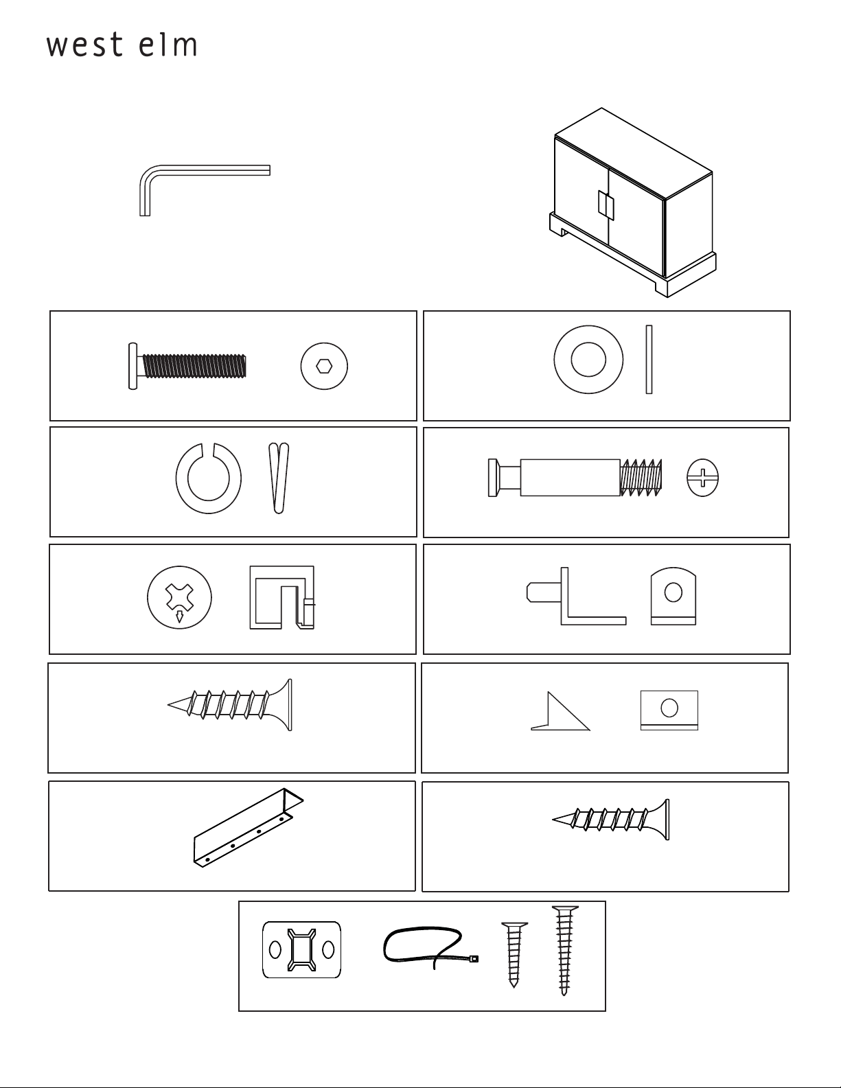
! Tools supplied:
! Do not throw away packaging materials until assembly is complete.
! Assemble this item on a soft surface, such as cardboard or carpet, to protect
! Proper assembly of this item requires 2 people.
Hardware
plinthe base console
assembly instructions
finish.
G
A
C
E
bolts 6mm x 30mm 6x
lock washer 6x
com lock 12x
B
flat washer 6x
D
cam bolt 12x
F
shelf pin 16x
H
screw(black nickel) 6x
I J
handle 2x
Anti tip kit 2x
Nylon Strap 2x
Mounting Plate 4x
plastic clasp 6x
screw (white nickel) 8x
Small Screw 4x Large Screw 4x
Page 1 of 9 - 1739739/36397339 03.27.09
Page 2
plinthe base console
assembly instructions
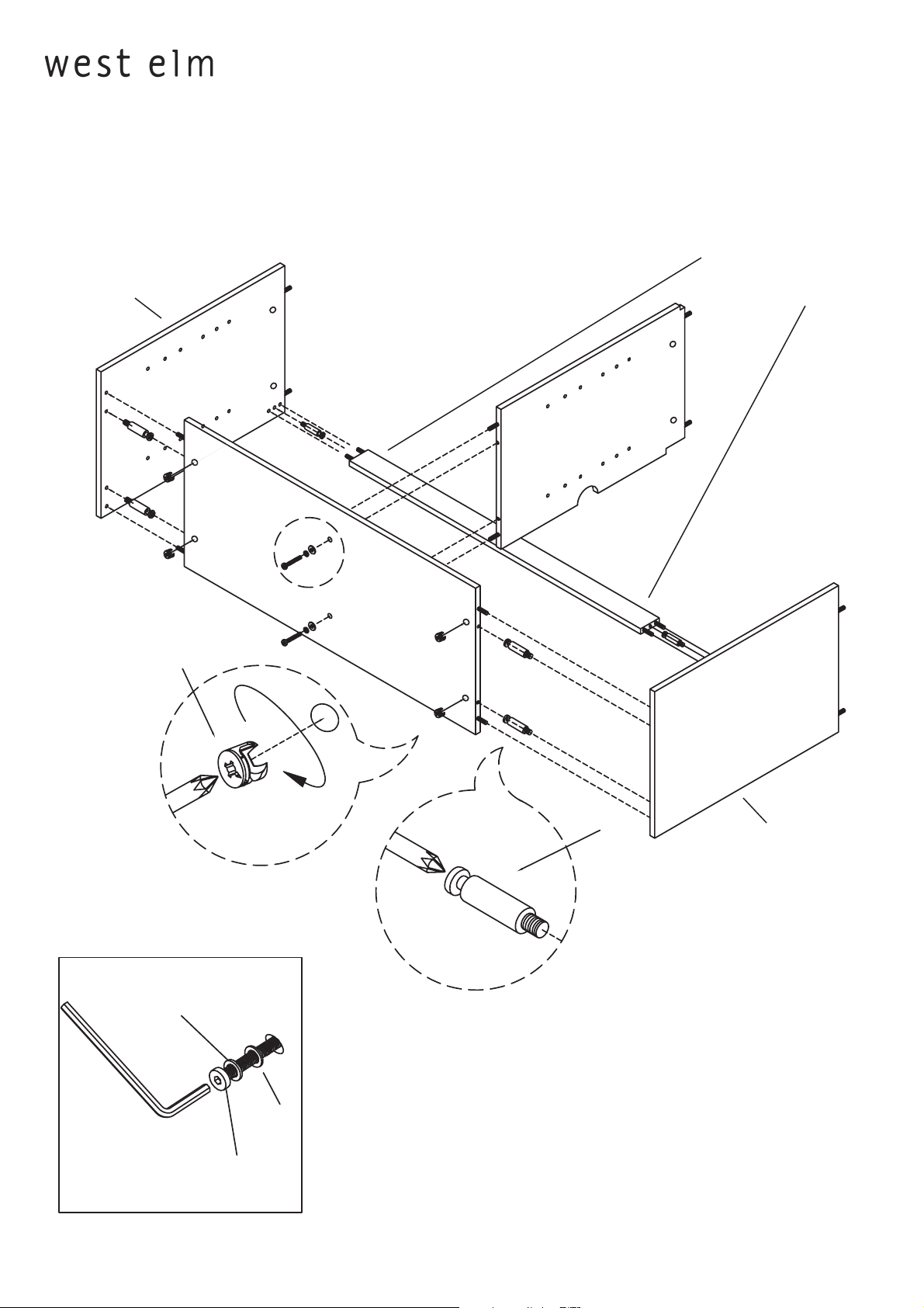
1. At the top and bottom of the end panel screw in cam bolts (D) as the drawing shows. Insert cam locks
(E) into bottom panel and back rail. Align bottom panel and back rail with the cam bolts and press
rmly into place. Turn cam lock clockwise to lock bottom panel and back rail in place. Next, align
partition with the bottom panel. Insert bolts (A), lock washers (C) and at washers (B) and tighten
with supplied hex key. Do not overtighten.
insert cam locks
End panel
into back of rail
Partition
Bottom panel
E
6x
6x
Back rail
D
End panel
2x
C
B
A
Page 2 of 9 - 1739739/36397339 03.27.09
Page 3
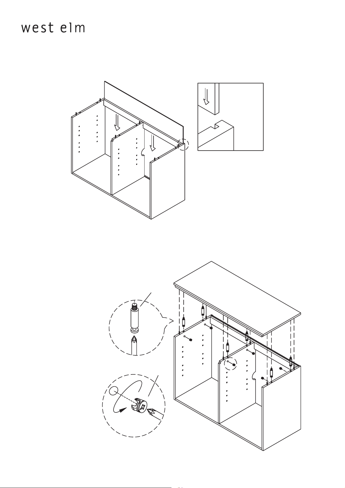
2. Slide back panel down into grooves in back of the
End panels like the drawing shows.
plinthe base console
assembly instructions
3. Insert cam bolts (D) into the bottom of the top panel. Insert cam locks (C) into the sides of the partitions
and end panels. Press the top down onto the case and tighten the cam lock clockwise with a screwdriver.
D
6x
E
6x
Page 3 of 993379363/9379371 - 01.16.09
Page 4

plinthe base console
assembly instructions
4. Align base with bottom panel.Insert bolts (A) ,lock washer (C),and aft washer (B).Tighten
with supplied hex key.Do not over tighten.
B
C
A
Page 4 of 993379363/9379371 - 01.16.09
Page 5

plinthe base console
assembly instructions
5. Press plastic clasps into grooves on back of unit like drawing shows. Insert screws into claps. Tighten with
screwdriver.
H
G
6x
Page 5 of 993379363/9379371 - 01.16.09
Page 6

plinthe base buffet
assembly instructions
5. Align door handle (G) with notch on door. Insert screws (H) through door handle (G) into door.
Do Not Overtighten!
H
G
Page 6 of 99379363/9379371 - 01.16.09
Page 7

plinthe base buffet
assembly instructions
6. Attach doors to hinges preassembled on inside of end panel. Use a screwdriver on the back screw to
adjust the doors once the are installed.
F
7. Open doors straight out. insert shelf pins (F) into the desired holes in the end panels and partitions.
Carefully slide shelves into place.
Page 7 of 99379363/9379371 - 01.16.09
Page 8

plinthe base buffet
Note: Hinges are adjustable. A combination of these adjustments may be necessary to level doors.
assembly instructions
FOR SIDE adjustment (adjusting the gap between doors
and leveling doors)
1. Adjust gap by turning screw B
FOR DEPTH adjustment (adjusting how close the doors
rest against the cabinet):
1. Loosen screw A .
2. Adjust depth.
3. Re-tighten screw A .
FOR HEIGHT adjustment
1. Loosen screw C (both screws)
2. Adjust height.
3. Re-tighten screws.
TO ADJUST LEFT DOOR IN BELOW EXAMPLE:
1. Adjust top hinge by turning screw B clockwise
2. Adjust bottom hinge by turning screw B counterclockwise.
c
A
B
c
TO ADJUST RIGHT DOOR IN BELOW EXAMPLE:
1. Adjust top hinge by turning screw B counterclockwise
2. Adjust bottom hinge by turning screw B clockwise.
Page 8 of 99379363/9379371 - 01.16.09
Page 9

plinthe base console
assembly instructions
NOTICE: To prevent injury and property damage from unexpected tipping of furniture, we highly
recommend installation of the anti-tip kit included with this product.
Attaching unit to wall with anti-tip kits.
1. Determine where the unit is to be placed and mark location on the wall for the mounting bracket
screw holes. They should be placed approximatly 1” below the top on the back of the unit.
2. Attach the mounting bracket vertically to the wall by inserting the long screws provided through the
holes in the bracket and tightening securely using screwdriver. Screws must penetrate wall studs for
proper installation.
3. Next using the short screws attach the 2nd bracket to the back of the unit top.
4. Lace the nylon strap down through the brackets. Slide the thin end of the strap through the
receiving end of the nylon strap. Pull to tighten tower snug against wall.
Long Screw
Short Screw
Adjustable levelers are installed in the base to
ooring. To adjust these levelers,
CARE INSTRUCTIONS
Hardware may loosen overtime. Periodically check that all connections are tight.
nish, avoid the use of chemicals and household cleaners.
simply turn them counterclosckwise to raise the base .
Page 9 of 993379363/9379371 - 01.16.09
 Loading...