


Draft 1 – 07/11/06
MEDIA GATEWAY™(MODEL WMT)
USER GUIDE
Copyright © 2006 Westell, Inc. 030-300417 Rev. A

Draft 1 - 07/11/06
User Guide
Media Gateway (Model WMT)
TABLE OF CONTENTS
1. PRODUCT DESCRIPTION ..................................................................................................................................4
2. SAFETY INSTRUCTIONS ...................................................................................................................................4
3. CARING FOR YOUR MEDIA GATEWAY.........................................................................................................4
4. REGULATORY INFORMATION ........................................................................................................................5
4.1 FCC Compliance Note...............................................................................................................................5
4.2 Canada Certification Notice..................................................................... Error! Bookmark not defined.
5. NETWORKING REQUIREMENTS .....................................................................................................................7
6. HARDWARE FEATURES.................................................................................................................................... 8
6.1 LED Indicators...........................................................................................................................................8
7. INSTALLING THE HARDWARE........................................................................................................................9
7.1 Installation Requirements ..........................................................................................................................9
7.2 Before you begin........................................................................................................................................9
7.3 Hardware Installations ............................................................................................................................. 10
8. CONFIGURING MEDIA GATEWAY FOR INTERNET CONNECTION........................................................13
8.1 Setting Up an Account Profile .................................................................................................................13
8.2 Establishing a PPP Session ......................................................................................................................18
8.3 Disconnecting a PPP Session...................................................................................................................20
9. SETTING UP MACINTOSH OS X..................................................................................................................... 22
10. SETTING UP ADVANCED CONFIGURATION ..............................................................................................26
11. HOME ..................................................................................................................................................................27
11.1 Adding Account Profiles..........................................................................................................................28
11.2 Editing Account Profiles..........................................................................................................................29
12. STATUS...............................................................................................................................................................31
12.1 Connection Summary...............................................................................................................................31
12.2 About .......................................................................................................................................................32
13. CONFIGURATION .............................................................................................................................................33
13.1 Single Static IP – Single IP Address PassThrough ..................................................................................33
13.2 Service Configuration ..............................................................................................................................38
13.3 Firewall Configuration.............................................................................................................................50
13.4 Wireless Configuration ............................................................................................................................54
13.5 Advanced LAN ........................................................................................................................................ 60
13.6 Advanced WAN....................................................................................................................................... 76
14. SETTING UP ADVANCED SERVICE CONFIGURATION............................................................................. 90
14.1 Port Forwarding Ranges of Ports.............................................................................................................91
030-300417 Rev. A 2 July 2006

Draft 1 - 07/11/06
User Guide
14.2 Adding Port Forwarding Ports .................................................................................................................91
14.3 Port Forwarding Trigger Ports ................................................................................................................. 92
14.4 Adding Local Trigger Ports .....................................................................................................................93
14.5 Static NAT ...............................................................................................................................................94
14.6 Enabling Static NAT................................................................................................................................ 95
14.7 Disabling Static NAT...............................................................................................................................96
15. MAINTENANCE.................................................................................................................................................98
15.1 Backup/Restore........................................................................................................................................98
15.2 Firewall Log.............................................................................................................................................99
15.3 Administrative Password .......................................................................................................................101
15.4 Remote Access.......................................................................................................................................102
15.5 Update Device........................................................................................................................................103
16. TROUBLESHOOTING .....................................................................................................................................108
16.1 System Self Tests...................................................................................................................................108
16.2 Diagnostic Logs .....................................................................................................................................110
16.3 Statistics ................................................................................................................................................. 114
Media Gateway (Model WMT)
16.4 Wireless Statistics ..................................................................................................................................116
16.5 Status......................................................................................................................................................118
17. NAT SERVICES................................................................................................................................................124
18. TECHNICAL SUPPORT INFORMATION ...................................................................................................... 128
19. PRODUCT SPECIFICATIONS.........................................................................................................................128
20. SOFTWARE LICENSE AGREEMENT............................................................................................................129
21. PUBLICATION INFORMATION.....................................................................................................................131
030-300417 Rev. A 3 July 2006

Draft 1 - 07/11/06
User Guide
Media Gateway (Model WMT)
1. PRODUCT DESCRIPTION
The Westell® Media Gateway Communications Subsystem provides reliable, high-speed, Internet access to your
existing phone line. Installation is easy ... no tools ... no headaches. Simply connect the hardware, apply power, and
perform the simple software configuration for the Media Gateway and you are on the Internet.
The Media Gateway is capable of data rates hundreds of times faster than a traditional analog modem. But unlike
analog modems, the Media Gateway allows you to use the same phone line for simultaneous voice/fax
communications and high-speed Internet access, eliminating the need for dedicated phone lines for voice and data
needs. The Media Gateway supports a variety of networking interfaces such as wireless 802.11b/g and Ethernet.
Note: Hereafter, the Westell Media Gateway™ Communications Subsystem will be referred to as “Media Gateway,”
“Gateway,” or “Modem.”
2. SAFETY INSTRUCTIONS
Never install any telephone wiring during a lightning storm.
Never install telephone jacks in wet locations unless the jack is specifically designed for wet locations.
Never touch non-insulated telephone wires or terminals unless the telephone line has been disconnected at the
network interface.
Use caution when installing or modifying telephone lines.
WARNING
Risk of electric shock. Voltages up to 140 Vdc (with reference to
ground) may be present on telecommunications circuits.
3. CARING FOR YOUR MEDIA GATEWAY
Please follow these guidelines to ensure the best use of your Media Gateway.
x When using Stylus pen (Media Gateway in iobi mode), please be sure to gently tap the components in the LCD
screen to navigate to various Iobi features.
x DO NOT use a pen, pencil or other pointed object on the LCD screen as these items may cause damage to the
screen. Always use the point of the Stylus for tapping on the LCD screen and making selections.
x Warning: DO NOT use an abrasive cleaner on the LCD screen as this will damage the screen. If the LCD
becomes soiled, use a damp, clean cloth moistened with a window-cleaning solution to gently wipe the
screen.
030-300417 Rev. A 4 July 2006

Draft 1 - 07/11/06
User Guide
Media Gateway (Model WMT)
4. REGULATORY INFORMATION
4.1 FCC Compliance Note
(FCC ID: CH8A90WMT-00)
This equipment has been tested and found to comply with the limits for a Class B digital device, pursuant to Part 15
of the Federal Communication Commission (FCC) Rules. These limits are designed to provide reasonable protection
against harmful interference in a residential installation. This equipment generates, uses, and can radiate radio
frequency energy, and if not installed and used in accordance with the instructions, may cause harmful interference
to radio communications. However, there is no guarantee that interference will not occur in a particular installation.
If this equipment does cause harmful interference to radio or television reception, which can be determined by
turning the equipment OFF and ON, the user is encouraged to try to correct the interference by one or more of the
following measures:
x Reorient or relocate the receiving antenna.
x Increase the separation between the equipment and the receiver.
x Connect the equipment to a different circuit from that to which the receiver is connected.
x Consult the dealer or an experienced radio/TV technician for help.
Modifications made to the product could void the users’ right to operate the equipment.
PART 68 - COMPLIANCE REGISTRATION
This equipment (Model WMT) complies with Part 68 of the FCC rules and the requirements adopted by the ACTA.
A label on the bottom of this equipment contains, among other information, the Ringer Equivalence Number (REN)
and the product identifier. For products approved after July 23, 2001 the product identifier is in the format
US:AAAEQ##TXXXX. The digits represented by ## are the REN without a decimal point (e.g. 03 is a REN of 0.3).
The REN is used to determine the number of devices that may be connected to a telephone line. For earlier products,
the REN is separately shown on the label. If requested, this number must be provided to the telephone company.
Excessive RENs on a telephone line may result in the devices not ringing in response to an incoming call. In most,
but not all areas, the sum of RENs should not exceed five (5.0). To be certain of the number of devices that may be
connected to a line, as determined by the total RENs, contact the local telephone company.
This equipment is designated to connect to the telephone network or premises wiring using a compatible modular
jack that is Part 68 compliant. An FCC compliant telephone cord and modular plug is provided with the equipment.
See the Installation Information section of this User Guide for details.
030-300417 Rev. A 5 July 2006

Draft 1 - 07/11/06
User Guide
A plug and jack used to connect this equipment to the premises wiring and telephone network must comply with the
applicable FCC Part 68 rules and requirements adopted by the ACTA. A compliant telephone cord and modular plug
is provided with this product. It is designed to be connected to a compatible modular jack that is also compliant. See
installation instruction for details.
If this terminal equipment (Model WMT) causes harm to the telephone network, the telephone company may
request you to disconnect the equipment until the problem is resolved. The telephone company will notify you in
advance if temporary discontinuance of service is required. If advance notification is not practical, the telephone
company will notify you as soon as possible. You will be advised of your right to file a complaint with the FCC if
you believe such action is necessary.
The telephone company may make changes to their facilities, equipment, operations, or procedures that could affect
the operation of this equipment. If this happens, the telephone company will provide advance notice in order for you
to make the modifications necessary to maintain uninterrupted service.
If your home has specially wired alarm equipment connected to the telephone line, ensure that the installation of this
equipment (Model WMT) does not disable your alarm equipment. If you have questions about what will disable
alarm equipment, consult your telephone company or a qualified installer.
This equipment cannot be used on public coin phone service provided by the telephone company. Connection of this
equipment to party line service is subject to state tariffs.
Media Gateway (Model WMT)
030-300417 Rev. A 6 July 2006

Draft 1 - 07/11/06
User Guide
Media Gateway (Model WMT)
5. NETWORKING REQUIREMENTS
The following system specifications are required for optimum performance of the Media Gateway via 10/100 BaseT Ethernet or Wireless installations.
CONNECTION TYPE
10/100 Base-T
ETHERNET
WIRELESS
IEEE 802.11g
x Pentium
x Microsoft® Windows
Macintosh
x 64 MB RAM (128 MB recommended)
x 10 MB of free hard drive space
x TCP/IP Protocol stack installed
x 10/100 Base-T Network Interface Card (NIC)
x Computer Operating System CD-ROM on hand
x Pentium
x Microsoft
Macintosh® OS X installed
x Computer Operating System CD-ROM on hand
x Internet Explorer 4.x or Netscape Navigator 4.x or higher
x 64 MB RAM (128 MB recommended)
x 10 MB of free hard drive space
x An available IEEE 802.11b/g PC adapter
MINIMUM SYSTEM REQUIREMENTS
® or equivalent class machines
® (98 SE, ME, NT 4.0, 2000, or XP)
® OS X, or Linux installed
® or equivalent class machines
® Windows® (98 SE, ME, 2000, or XP) or
030-300417 Rev. A 7 July 2006

Draft 1 - 07/11/06
User Guide
Media Gateway (Model WMT)
6. HARDWARE FEATURES
6.1 LED Indicators
This section describes the LED indicators located on the front of the Media Gateway. The LEDs described in this
section are used to verify the unit’s operation and status. Refer to the following chart for details on the LEDs.
LED States and Descriptions
LED State Description
Solid Green
OFF
POWER
Solid Red
ETHERNET
(E1/WAN, E2, E3, E4)
WIRELESS
INTERNET
LINE IN USE
NOTE: Safe Boot is reflected when the Power and Internet LED’s are both Red and all other LED’s are off.
Solid Green
OFF
Solid Green
OFF
Solid Green
Solid Red
OFF
Solid Blue
OFF
Media Gateway power is ON.
Media Gateway power is OFF.
CS POST (Power On Self Test), Failure (not bootable) or Device
Malfunction. Note: The Power LED should be red no longer than
two seconds after the power on self test passes.
Powered device is connected to one or more of the Ethernet ports
(includes devices with wake-on LAN capability where slight
voltage is supplied to an Ethernet connection).
Communication Subsystem power is OFF, no cable or no
powered device is connected to the Ethernet ports.
Link Established.
Media Gateway power is OFF or No Link.
IP connected (the Subsystem has a WAN IP address from IPCP
or DHCP, or a static IP address is configured. PPP negotiation
has successfully completed.
Device attempted to become IP connected and failed (no DHCP
response, no PPPoE response, PPPoE authentication failed, no IP
address from IPCP, etc.).
Media Gateway power is OFF, Media Gateway is in Bridge
Mode, or an Internet connection is not present.
Indicates telephone is in use (off-hook)
Indicates telephone is not in use (on-hook)
030-300417 Rev. A 8 July 2006

Draft 1 - 07/11/06
User Guide
7. INSTALLING THE HARDWARE
7.1 Installation Requirements
To install the Media Gateway, you will need the following:
x A Network Interface Card (NIC) installed in your PC, or
x An IEEE 802.11b/g adapter
7.2 Before you begin
Make sure that your kit contains the following items:
x Media Gateway Base Unit
x Power Supply
x RJ-45 Ethernet cable (straight-through) (yellow)
x RJ-11 Phone cable
x Cordless Handset and Battery
x Base Unit Stand
x Stylus
x Media Gateway CD-ROM
x Quick Start Guide
Media Gateway (Model WMT)
030-300417 Rev. A 9 July 2006

Draft 1 - 07/11/06
User Guide
Media Gateway (Model WMT)
7.3 Hardware Installations
NOTE: If you are using Your Media Gateway in conjunction with an Ethernet Hub or Switch, refer to the
manufacturer’s instructions for proper installation and configuration. Westell recommends the use of a surge
suppressor to protect equipment attached to the AC power supply.
7.3.1 Installation via 10/100 Base-T Ethernet
NOTE: Before you connect via 10/100 Base-T, you must have an available Ethernet card installed in your
computer. If your Ethernet card does not auto-negotiate, you must set it to half duplex. Refer to the
!
Ethernet card manufacturer’s instructions for installing and configuring your Ethernet card.
1. Connect the yellow Ethernet cable from the Ethernet (E2, E3, or E4) jacks marked on the rear panel of the
base unit to the Ethernet port on your computer. Repeat this step to connect up to two additional PCs to the
Media Gateway.
NOTE: You may connect to any of the three Ethernet (E2, E3, or E4) jacks on the rear panel of the Media
Gateway base unit as they serve as an Ethernet switch.
2. Connect the DC 12V power supply cord to the power connector marked 12V AC~ on the rear panel of the base
unit. Plug the other end of the power supply into an AC wall socket, and then turn on the power switch (if it is
not already turned on).
3. Check to see if the Power LED is solid green. If the Power LED is solid green, the base unit is powered up.
4. Check to see if the Ethernet LED on the base unit is solid green. Solid green indicates that the Ethernet interface
is functioning properly.
5. After you have completed section 8 of this document and established an Internet connection, the Internet LED
will be solid green. If this LED is not solid green, please refer to your ISP’s instructions for establishing an
Internet connection or to section 6.1 (LED Indicators) of this document for information on the LEDs.
Congratulations! You have completed the Ethernet hardware installation. Proceed to section 8 to configure your
Media Gateway for an Internet connection.
030-300417 Rev. A 10 July 2006

Draft 1 - 07/11/06
User Guide
Media Gateway (Model WMT)
7.3.2 Connecting PCs via Wireless
IMPORTANT: If you are connecting to your Media Gateway via a wireless network adapter, the SSID must be the
same for both the Media Gateway and your PC’s wireless network adapter. The default SSID for Media Gateway is
the serial number of the unit (located below the bar code on the bottom of the unit and also on the Westell shipping
carton). Locate and run the utility software provided with your PC’s Wireless network adapter and enter the SSID
value. The PC’s wireless network adapter must be configured with the SSID (in order to communicate with the
Media Gateway) before you begin the account setup and configuration procedures. Later, for privacy, you can
change the SSID by following the procedures outlined in section 13.4 (Wireless Configuration).
NOTE: Client PCs can use any Wireless Fidelity (Wi-Fi) 802.11b/g certified card to communicate with the Media
Gateway. The Wireless card and Media Gateway must use the same Wired Equivalent Privacy (WEP) security code
type. The factory default for WEP is DISABLED. If you enable WEP, you must ensure the network setting for your
wireless adapter is set to “Must Use Shared Key for WEP” or “Open Wi-Fi.” You must ensure that your PC’s Wi-Fi
adapter is configured properly for whichever network setting you use. You can access the settings in the advanced
properties of the wireless network adapter.
To network Media Gateway using a wireless installation, you will need to confirm the following:
1. Ensure that an 802.11b/gwireless network adapter has been installed in the PC on your wireless network.
2. Install the appropriate drivers for your Wireless IEEE802.11b or IEEE802.11g adapter used with your PC.
3. Connect the DC 12V power supply cord to the power connector marked 12V AC~ on the rear panel of the base
unit. Plug the other end of the power supply into an AC wall socket, and then turn on the power switch (if it is
not already turned on).
4. Check to see if the Power LED is solid green. If the Power LED is solid green, the base unit is powered up.
5. Check to see if the Wireless LED is solid Green. This means that the Wireless interface is functioning properly.
6. After you have completed section 8 of this document and established an Internet connection, the Internet LED
will be solid green. If this LED is not solid green, please refer to your ISP’s instructions for establishing an
Internet connection or to section 6.1 (LED Indicators) of this document for information on the LEDs.
NOTE: After you have initially connected Media Gateway using a wireless installation, you can network the Media
Gateway to additional computers in your home or office by completing steps 1 and 2 in this section for each PC that
you want on your wireless network.
Congratulations! You have completed the Wireless installation for the Media Gateway. You must now go to section
8 to configure Media Gateway for an Internet connection.
030-300417 Rev. A 11 July 2006

Draft 1 - 07/11/06
User Guide
Media Gateway (Model WMT)
7.3.3 Ethernet and Wireless Combination Installation
Media Gateway supports simultaneous use of 10/100 Base-T Ethernet and Wireless configurations. The following
instructions explain how to install Media Gateway for simultaneous use of Ethernet and Wireless ports.
NOTE: Refer to section 7.3.1 and 7.3.2 for instructions on hardware installation via Ethernet and Wireless
connections, respectively.
1. Ensure that an 802.11b/g wireless network adapter has been installed in the PC on your wireless network.
2. Install the appropriate drivers for your Wireless IEEE802.11b or IEEE802.11g adapter used with your PC.
3. Connect the yellow Ethernet cable from the Ethernet (E2, E3, or E4) jack marked
base unit to the Ethernet port on your computer. Repeat this step to connect up to two additional PCs to the base
unit.
NOTE: You may connect to any of the three Ethernet (E2, E3, or E4) jacks on the rear panel of the Media
Gateway base unit as they serve as an Ethernet switch.
4. Connect the DC 12V power supply cord to the power connector marked 12V AC~ on the rear panel of the base
unit. Plug the other end of the power supply into an AC wall socket, and then turn on the power switch (if is it
not already turned on).
on the rear panel of the
5. Check to see if the Power LED is solid green. If the Power LED is solid green, the base unit is powered up.
6. Check to see if the Ethernet LED is solid green. Solid green indicates the Ethernet interface is functioning
properly.
7. Check to see if the Wireless LED is solid Green. This means that the Wireless interface is functioning properly.
8. After you have completed section 8 of this document and established an Internet connection, the Internet LED
will be solid green. If this LED is not solid green, please refer to your ISP’s instructions for establishing an
Internet connection or to section 6.1 (LED Indicators) of this document for information on the LEDs.
NOTE: After you have initially connected Media Gateway using a wireless installation, you can network Media
Gateway to additional computers in your home or office by completing steps 1 and 2 in this section for each PC that
you want on your wireless network.
Congratulations! You have completed the simultaneous hardware (Ethernet and Wireless) installation. You must
now go to section 8 to configure Media Gateway for an Internet connection.
030-300417 Rev. A 12 July 2006
Draft 1 - 07/11/06
User Guide
Media Gateway (Model WMT)
8. CONFIGURING MEDIA GATEWAY FOR INTERNET CONNECTION
To browse the Internet using your Media Gateway, you must set up your account profile and establish a PPP session
with your ISP.
NOTE: The PPPoE protocol is often used to establish an Internet connection. However, if your Internet service
provider does not support PPPoE, please refer to your service provider’s instructions for establishing an Internet
connection. If you are using PPPoE to establish your Internet connection, please following the instructions provided
in this section.
8.1 Setting Up an Account Profile
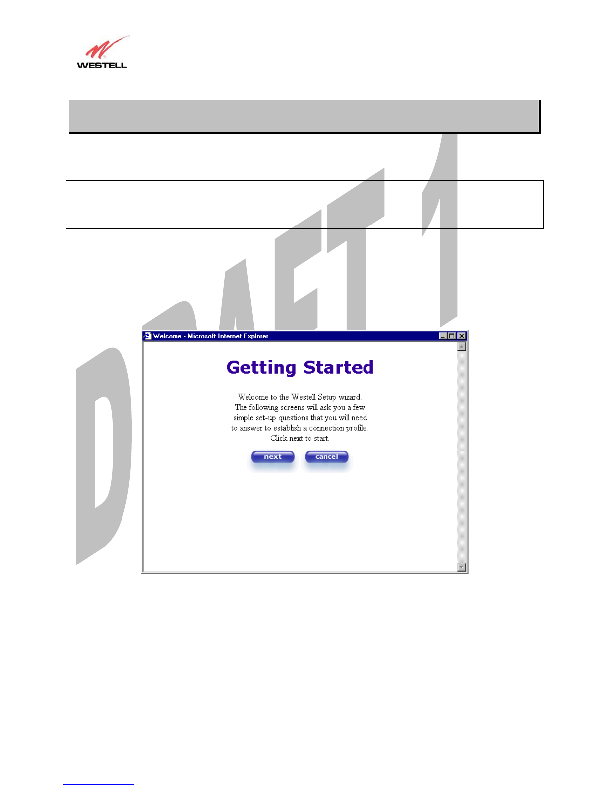
After you complete the hardware connection for your Media Gateway, power up the unit. Next, bring up your
computer’s Web browser and type http://192.168.1.254 in the browser’s address window, and then press Enter on
your keyboard. The Getting Started screen will appear. Click on next to continue.
030-300417 Rev. A 13 July 2006
Draft 1 - 07/11/06
User Guide
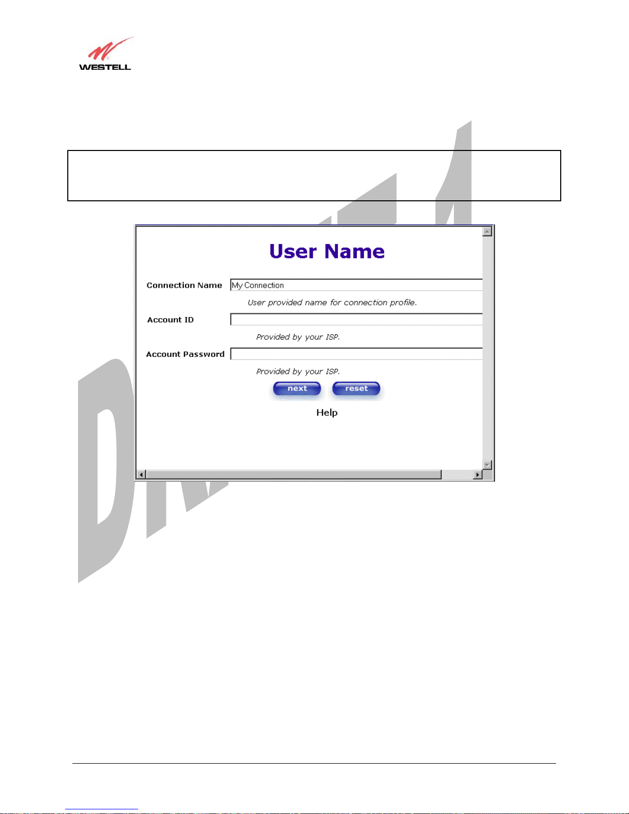
If you clicked on Next, the following screen will be displayed. This screen will allow you to set up your account
profile.
NOTE: Before you set up your account profile, you must obtain your Account ID, Account Password, and
VPI/VCI values from your ISP. You will use this information when you set up your account parameters. If you are
at a screen and need help, click on the Help button to learn more about the screen, or see section Error! Reference
source not found. (Help) for additional information on the help messages.
Media Gateway (Model WMT)
Type in your account parameters. (Account parameters are required before connecting to the Internet.)
Account Parameters include:
Ɣ Connection Name-the Connection Name is a word or phrase that you use to identify your account.
(You may enter up 64 characters in this field.)
Ɣ Account ID-the Account ID is provided by your ISP.
(You may enter up 255 characters in this field.)
Ɣ Account Password-the Account Password is provided by your ISP.
(You may enter up 255 characters in this field.)
030-300417 Rev. A 14 July 2006

Draft 1 - 07/11/06
User Guide
Media Gateway (Model WMT)
When you enter your account parameters at the User Name screen, they will be displayed as shown in the screen
below. Click next if you want your account parameters to take effect. Click on reset if you do not want the account
parameters that you entered to take effect or if you want to re-enter the parameters.
Enter the VPI and VCI values (0 for VPI and 35 for VCI default) you obtained from your ISP. Click on next.
NOTE: The VPI/VCI screen will come preconfigured and it will be displayed here. Do
not change any values in this screen. Click
next to go to the PROTOCOL screen.
VPI = 0
VCI = 35
030-300417 Rev. A 15 July 2006
Draft 1 - 07/11/06
User Guide
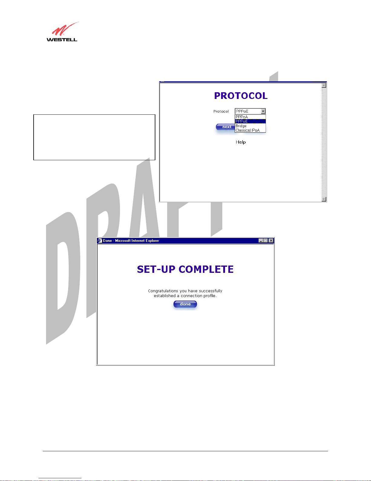
Select the Protocol type that you obtained from your ISP. Click on next.
NOTE: The PROTOCOL screen will come
pre-configured and it will be displayed here.
Click next to go to the SET-UP
COMPLETE screen.
When the SET-UP COMPLETE screen appears, you have successfully completed your Account Profile setup.
Click on done.
Media Gateway (Model WMT)
030-300417 Rev. A 16 July 2006
Draft 1 - 07/11/06
User Guide
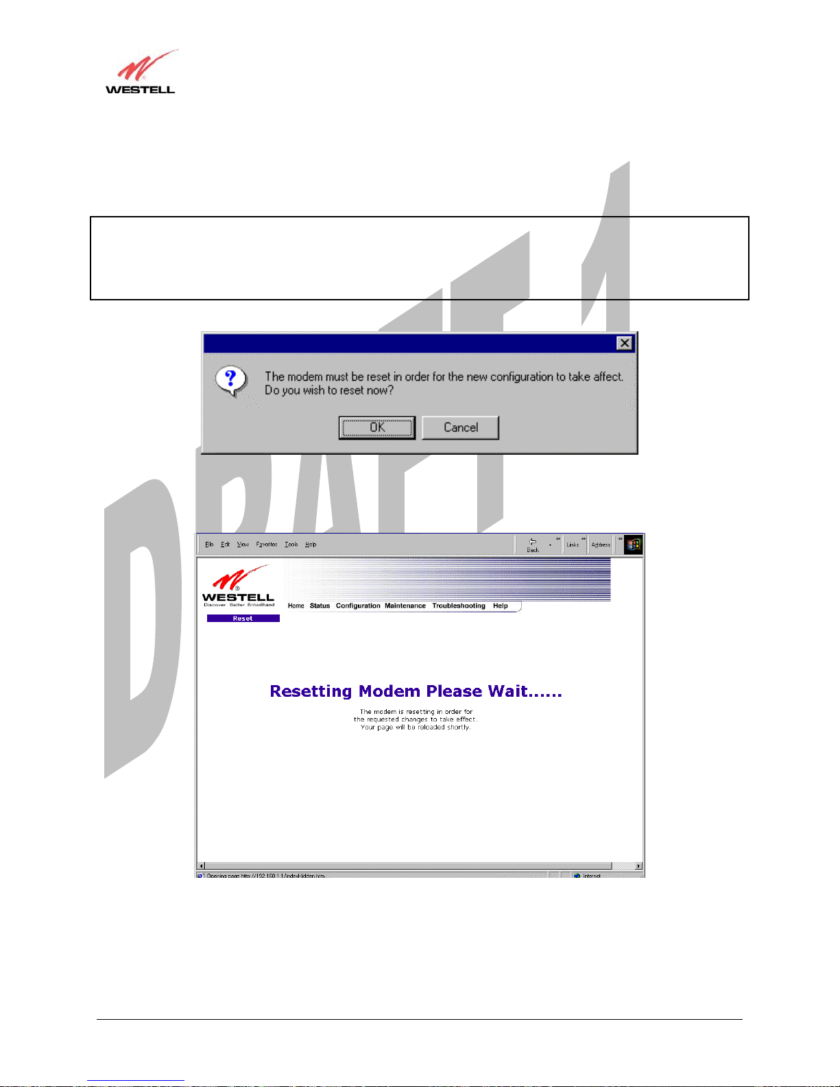
If you changed the VPI/VCI settings and clicked on done in the SET-UP COMPLETE screen, the following
screen will appear. Click on OK.
NOTE: The following pop-up will appear only if you have changed the VPI, VCI, or Protocol values in the
preceding screens. If you did not change any of these values, this pop-up screen will not appear and Media Gateway
will not be reset. If the Media Gateway’s connection setting is set to “Always On” and you have changed any of
these values, Media Gateway will reset automatically. For instructions on editing your connection settings, see
section 11.2.
If you clicked on OK, the following screen will be displayed. Media Gateway will be reset and the new
configuration will take effect.
Media Gateway (Model WMT)
030-300417 Rev. A 17 July 2006
Draft 1 - 07/11/06
User Guide
Media Gateway (Model WMT)
8.2 Establishing a PPP Session
View the PPP Status at the Home page. If the PPP Status displays DOWN, click the Connect button to establish a
PPP session.
NOTE: Whenever the PPP Status displays DOWN, you do not have a PPP session established. If the Media
Gateway’s connection setting is set to “Always On” or “On Demand,” after a brief delay the PPP session will be
established automatically and the PPP Status will display UP. If the connection setting is set to “Manual,” you must
click on the Connect button to establish a PPP session. Once the PPP session has been established (PPP Status
displays UP), you may proceed with the Media Gateway’s configuration. Section 11.2 provides instructions on
editing the connection settings. (Refer to the ‘Edit My Connection’ screen.) The Media Gateway’s factory default
connection setting is “Manual.”
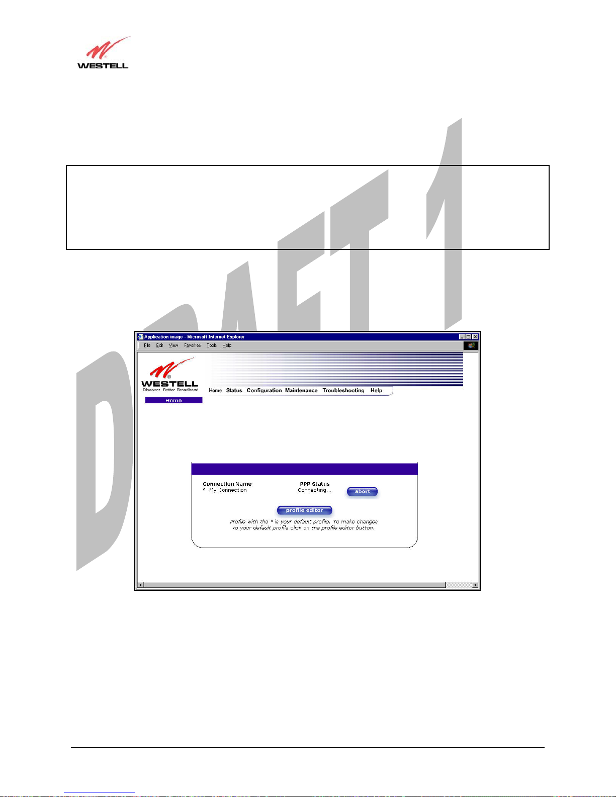
If you click the Connect button, the following screen will appear briefly. The PPP Status in the Connection
Overview window allows you to view the state of your Media Gateway connection. When the PPP Status displays
Connecting…, this means that you are establishing a PPP session.
030-300417 Rev. A 18 July 2006

Draft 1 - 07/11/06
User Guide
After a PPP session has been established, the PPP Status will display UP. Congratulations! You may now browse
the Internet.
Media Gateway (Model WMT)
For example, if you want to visit BellSouth’s home page, type http://www.bellsouth.com in your browser’s address
window.
030-300417 Rev. A 19 July 2006

Draft 1 - 07/11/06
User Guide
Media Gateway (Model WMT)
8.3 Disconnecting a PPP Session
If you have finished browsing the Internet and want to disconnect from your PPP session, click on the Disconnect
button in the Connection Overview screen (the preceding screen). The following pop-up screen will appear. Click
on OK to disconnect the PPP session.
Warning: If you disconnect the PPP session, this will disconnect Media Gateway from the Internet, and all
computers on the LAN will be disconnected until the PPP session is re-established.
If you clicked the Disconnect button in the preceding Connection Overview screen, the PPP Status should display
DOWN. This means that you no longer have a PPP session (no IP connection to your ISP).
030-300417 Rev. A 20 July 2006

Draft 1 - 07/11/06
User Guide
When you are ready to re-establish a PPP session, click on the connect button.
NOTE: When you are ready to exit the Gateway’s interface, click on the X (close) in the upper-right corner of the
window. Closing the window will not affect your PPP Status (your PPP session will not be disconnected). You must
click the disconnect button to disconnect your PPP session. When you are ready to restore the Media Gateway
interface, you must launch your Internet browser and type http://192.168.1.254/ in the browser’s address window
and press Enter on your keyboard.
Media Gateway (Model WMT)
030-300417 Rev. A 21 July 2006

Draft 1 - 07/11/06
User Guide
Media Gateway (Model WMT)
9. SETTING UP MACINTOSH OS X
This section provides instructions on how to use Macintosh Operating System 10 with the Media Gateway. Follow
the instructions in this section to create a new network configuration for Macintosh OS X.
Open the System Preference Screen
After you have connected Media Gateway to the Ethernet port of your Macintosh, the screen below will appear.
Click the “Apple” icon in the upper-right corner of the screen and select System Preferences.
Choose the Network Preferences
After selecting System Preferences…, from the previous screen, the System Preferences screen will be displayed.
From the System Preferences screen, click on the Network icon.
030-300417 Rev. A 22 July 2006

Draft 1 - 07/11/06
User Guide
Media Gateway (Model WMT)
Create a New Location
After selecting the Network icon at the System Preferences screen, the Network screen will be displayed. Select
New Location from the Location field.
Name the New Location
After selecting New Location from the Network screen, the following screen will be displayed. In the field labeled
Name your new location:, change the text from “Untitled” to “Westell.” Click OK.
030-300417 Rev. A 23 July 2006

Draft 1 - 07/11/06
User Guide
Media Gateway (Model WMT)
Select the Ethernet Configuration
After clicking on OK in the preceding screen, the Network screen will be displayed. The Network screen shows the
settings for the newly created location. From the Configure field in the Network screen, select Built-in Ethernet.
Click on Save.
NOTE: Default settings for the Built-in Ethernet configuration are sufficient to operate Media Gateway.
Check the IP Connection
To verify that the computer is communicating with Media Gateway, follow the instructions below.
1. Go to the “Apple” icon in the upper-right corner of the screen and select System Preferences.
2. From the System Preferences screen, click on the Network icon. The Network screen will be displayed.
3. From the Configure field in the Network screen, select Built-in Ethernet.
4. View the IP address field. An IP address that begins with 192.168.1 should be displayed.
NOTE: The DHCP server provides this IP address. If this IP address is not displayed, check The Gateway’s wiring
connection to the PC. If necessary, refer to section 7 for hardware installation instructions.
030-300417 Rev. A 24 July 2006

Draft 1 - 07/11/06
User Guide
Media Gateway (Model WMT)
Create a User Account
In the address window of your Internet Explorer web browser, type http://192.168.1.254, and then press Enter on
your keyboard. The Getting Started screen will be displayed. You may now begin your Account Setup. Refer to
section 8 (Configuring Media Gateway for Internet connection) to begin setting up your account.
030-300417 Rev. A 25 July 2006

Draft 1 - 07/11/06
User Guide
Media Gateway (Model WMT)
10. SETTING UP ADVANCED CONFIGURATION
Advanced Configuration instructions are explained in Section 11 through Section 17. If you want to set up advanced
features for the Media Gateway, follow the instructions provided in sections 11 through 17.
The Media Gateway Communications Subsystem allows you to make changes to advanced features such as account
profiles, routing configurations, and firewall settings. The following sections explain each feature and show you
how to make changes to the Media Gateway’s settings. A menu is displayed at the top of each screen and will allow
you to navigate to the various configuration options of your Media Gateway. If you are at a screen and need help,
click on the Help button to learn more about that screen.
030-300417 Rev. A 26 July 2006

Draft 1 - 07/11/06
User Guide
Media Gateway (Model WMT)
11. HOME
As you navigate through the various screens of Media Gateway Communications Subsystem, the name of the active
page that you have selected will appear in the upper-left side of the screen, as shown below. Please note that the
actual values may differ from the values displayed in the screens.
If you have set up your account profile and established your PPP session as discussed in section 8, the following
settings will be displayed when you click on your Home page. Click on profile editor to edit your connection
profile.
NOTE: If you have created multiple account profiles, select the option button for the active account profile.
Connection Name This Connection Name is from the connection profile that you established in section 8.
PPP Status UP = PPP session established
DOWN = No PPP session established.
Connect/Disconnect CONNECT = Establish a PPP session
030-300417 Rev. A 27 July 2006

Draft 1 - 07/11/06
User Guide
DISCONNECT = Disconnect a PPP session
Profile Editor This allows you to make changes to the profile that you created in section 8.
Media Gateway (Model WMT)
11.1 Adding Account Profiles
If you select the Profile Editor button from your Home page, the Advanced Home screen will appear, as shown
below. Click on the new connection button in the Advanced Home screen. The New Connection screen will
appear. Enter your account profile information and click on New. Next, click on OK in the pop-up screen to save
your new connection. If you do not want to add a connection profile, click on Close in the New Connection screen.
NOTE: NAT Profiles allow you to create specific service settings. A NAT Profile may be associated with a certain
connection setting, or NAT services. This allows you to customize the profile for specific users. You may store up to
eight unique user profiles in the Media Gateway. Details on the New Connection screen are located at the end of
this section.
If you clicked OK in the “Save new connection?” pop-up screen, the following screen will be displayed. This
screen will allow you to edit a connection profile. Select a profile name from the Connection Name field and click
on the edit button adjacent to the name.
030-300417 Rev. A 28 July 2006

Draft 1 - 07/11/06
User Guide
Media Gateway (Model WMT)
11.2 Editing Account Profiles
If you clicked on Edit in the preceding screen, the Edit “My Connection” screen will appear. Follow the steps in
the Edit “My Connection” screen to change your existing connection profile, which you set up in section 8. If you
do not want to change your connection profile, click on close in the screen. Click on delete if you want to delete
your connection profile.
030-300417 Rev. A 29 July 2006

Draft 1 - 07/11/06
User Guide
Connection Name This field allows you to enter a new connection name of your choice (up to 64
characters).
Account ID The account ID that you used in section 8.
Account Password The account password that you used in section 8.
Service Profile Westell recommends that you use the Default parameter.
Manual Factory default = MANUAL
Selecting this feature allows you to manually establish your PPP session.
On Demand Selecting this feature allows Media Gateway to automatically re-establish your
PPP session on demand anytime your PC requests Internet activity (for example,
browsing the Internet, email, etc.). When you have traffic, it may cause a delay.
Always On Selecting this feature allows Media Gateway to automatically establish a PPP
session when you log on, or if the PPP session goes down.
Time Out Enable Factory Default = DISABLED
Selecting this feature allows you to enable the timeout parameter of your PPP
session, which is set to a factory default of 20 minutes.
Save Password Selecting this feature allows you to save the password for your new connection
profile in Media Gateway so that you will not have to re-enter it in case of a
reboot.
Minutes for Connection Time Out This option allows you to specify the number of minutes that you want a PPP
session to stay active before it is disconnected due to inactivity. (This feature
works if you have selected the Time Out Enable feature explained above.)
Media Gateway (Model WMT)
030-300417 Rev. A 30 July 2006

Draft 1 - 07/11/06
User Guide
Media Gateway (Model WMT)
12. STATUS
12.1 Connection Summary
The following settings will be displayed if you select Connection Summary from the Status menu.
Note: The actual values may differ from the values displayed in this screen.
Connection Name This is from the connection profile that you established in section 8.
Connection Duration This field will display how long your PPP session has been connected.
Status This field will display the status of your PPP session.
UP=Connected
DOWN=Disconnected
Number of Reconnects This field will display the number of attempts that were made to establish a PPP session.
030-300417 Rev. A 31 July 2006
PPP Connection Information

Draft 1 - 07/11/06
User Guide
12.2 About
The following settings will be displayed if you select About from the Status menu.
Note: The actual values may differ from the values displayed in this screen.
Media Gateway (Model WMT)
Model Number Media Gateway manufacturer’s model number.
Serial Number Media Gateway manufacturer’s serial number.
MAC Address Media Access Controller (MAC) i.e., hardware address of this device.
Software Version Version of Application Software.
Software Model Media Gateway application type.
Description Product description.
Boot Loader Version of boot loader software
030-300417 Rev. A 32 July 2006

Draft 1 - 07/11/06
User Guide
Media Gateway (Model WMT)
13. CONFIGURATION
13.1 Single Static IP – Single IP Address PassThrough
The following settings will be displayed if you select Single Static IP from the Configuration menu. The Single
Static IP Configuration screen allows you to select the device on your LAN that will share your Single Static IP.
Before you begin this section, configure your PC settings to obtain an IP address from Media Gateway
automatically. (Refer to your Windows Help screen for instructions.)
NOTE: Single Static IP (SSI) allows the user to share the WAN assigned IP address with one device on the LAN.
By doing this, the device with the SSI becomes visible on the Internet. Network Address Translation (NAT) and
Firewall rules do not apply to the device configured for SSI. If you are using Bridge (Routed Bridge) protocol,
Single Static IP configuration will not be available.
STOP: Static NAT must be disabled before you can enable Single Static IP. To disable Static NAT, select Services
from the Configuration menu. Next, click on the static NAT button. Select the device from the Static NAT Device
drop-down menu and click on disable. Return to Single Static IP Configuration by selecting Single Static IP
Configuration from the Configuration menu.
030-300417 Rev. A 33 July 2006

Draft 1 - 07/11/06
User Guide
Media Gateway (Model WMT)
13.1.1 Enabling Single Static IP – Single IP Address PassThrough
To enable Single Static IP, select a device that will share your Single Static IP from the options listed in the window.
Click on enable.
NOTE: The Single Static IP Configuration screen allows you to select the device on your LAN that will share your
Single Static IP.
If you select a device and clicked on enable, the following pop-up screen will appear. Click on OK to enable this
device for Single Static IP. Click on Cancel if you do not want to enable Single Static IP.
NOTE: The actual device name may differ from the name displayed in this screen.
030-300417 Rev. A 34 July 2006

Draft 1 - 07/11/06
User Guide
If you clicked on OK in the preceding pop-up screen, the following pop-up screen will appear. Media Gateway must
be reset to allow the new configuration to take effect. Click on OK.
If you clicked on OK in the preceding screen, the following screen will be displayed. Media Gateway will be reset
and the new configuration will take effect.
Media Gateway (Model WMT)
After a brief delay, the home page will be displayed. Confirm that your PPP session displays UP. (Click on the
connect button to establish a PPP session). Next, Select Single Static IP from the Configuration menu to confirm
that Single Static IP is enabled, as shown in the following screen.
030-300417 Rev. A 35 July 2006

Draft 1 - 07/11/06
User Guide
Media Gateway (Model WMT)
STOP! After you enable Single Static IP, you must reboot your computer.
NOTE: If you chose to enable User Configured PC, wait for Media Gateway to reset and then manually enter the
WAN IP, Gateway, and Subnet mask addresses you obtained from your ISP into a PC.
13.1.2 Disabling Single Static IP – Single IP Address PassThrough
To disable Single Static IP, select Single Static IP from the Configuration menu. Click on disable.
030-300417 Rev. A 36 July 2006

Draft 1 - 07/11/06
User Guide
If you clicked on disable in the preceding screen, the following pop-up screen will be displayed. Click on OK.
If you clicked on OK in the Disable IP Passthrough? screen, the following pop-up screen will be displayed. This
screen will allow the modem to be reset and the new configuration will take effect. Click on OK.
Media Gateway (Model WMT)
If you clicked on OK in the preceding screen, the following screen will be displayed. Media Gateway will be reset
and the new configuration will take effect.
After a brief delay, the home page will be displayed. Confirm that your PPP session displays UP. (Click on the
connect button to establish a PPP session). Next, Select Single Static IP from the Configuration menu to confirm
that Single Static IP is disabled, as shown in the following screen.
030-300417 Rev. A 37 July 2006

Draft 1 - 07/11/06
User Guide
Media Gateway (Model WMT)
STOP! After you disable Single Static IP, you must reboot your computer.
13.2 Service Configuration
The following settings will be displayed if you select Services from the Configuration menu.
Westell has developed an extensive list of NAT services and you may select any service from this list. By selecting
your specific NAT service and setting up a NAT profile, you will ensure that the appropriate ports on Media
Gateway are open and that the required application traffic can pass through your LAN. For a list of supported
services, go to section 17 (NAT Services).
NAT Profiles allow you to create specific service settings. The NAT profile may then be associated with a
connection profile, allowing you to customize profiles for specific users. For example, if you want to attach specific
NAT services to a profile, or if you want to set up a different connection setting for a profile, you can create new
NAT profiles and customize them to your preference.
NOTE: You may create up to four NAT profiles and attach an unlimited number of services to each profile.
030-300417 Rev. A 38 July 2006

Draft 1 - 07/11/06
User Guide
Media Gateway (Model WMT)
Current Profile Displays the NAT (Network Address Translation) services that you have
selected.
Service Name Drop down selection menu of NAT (Network Address Translation) service you
can select to configure the Media Gateway.
UPNP Enable Factory Default = Disable
Enabling UPNP (Universal Plug and Play) allows automatic device discovery by
your operating system.
030-300417 Rev. A 39 July 2006

Draft 1 - 07/11/06
User Guide
Media Gateway (Model WMT)
13.2.1 Configuring UPNP on the Media Gateway
Note: To use the UPNP functionality in the Media Gateway, your Windows XP operating system must also support
UPNP. Please contact your computer manufacturer to verify that UPNP is enabled in your Windows XP operating
system.
To enable UPNP on Media Gateway perform the following steps:
1) Select Service Configuration from the Configuration screen
2) Click the UPNP Enable box (a check mark will appear in the box).
3) Follow the instructions in the pop-up screens.
4) Click OK to Reset the Media Gateway.
NOTE: When you are ready to disable UPNP, uncheck the UPNP Enable box in the Service Configuration screen.
If you click the UPNP Enable box in the Service Configuration screen, a check mark will appear in the box and
the following pop-up screen will be displayed. Click OK to continue.
If you click OK in the preceding screen, the following pop-up screen will be displayed. Click on OK to reset the
Media Gateway.
030-300417 Rev. A 40 July 2006

Draft 1 - 07/11/06
User Guide
If you clicked on OK in the preceding screen, the following screen will be displayed. Media Gateway will be reset
automatically, and the new configuration will take effect.
Media Gateway (Model WMT)
After a brief delay, the home page will be displayed. Confirm that your PPP session displays UP. (Click on the
connect button to establish a PPP session).
030-300417 Rev. A 41 July 2006

Draft 1 - 07/11/06
User Guide
Media Gateway (Model WMT)
13.2.2 Creating a New NAT Service Profile
NAT Profiles allow you to create specific service settings. The NAT profile may then be associated with a
connection profile, allowing you to customize profiles for specific users. For example, if you want to attach specific
NAT services to a profile, or if you want to set up a different connection setting for a profile, you can create new
NAT profiles and customize them to your preference.
NOTE: You may create up to four NAT profiles and attach an unlimited number of services to each profile.
To create a new NAT profile, click new in the Service Configuration screen.
If you select new from the preceding Service Configuration screen, the Create new Service Profile? pop-up
screen will be displayed. Click on OK to begin creating your new NAT service profile. Click Cancel if you do not
want to create a new NAT service profile.
030-300417 Rev. A 42 July 2006

Draft 1 - 07/11/06
User Guide
If you clicked on OK, the following screen will be displayed. Select “A New Service Profile #1” from the
Current Profile drop-down arrow.
Media Gateway (Model WMT)
If you selected “A New Service Profile #1” from the Current Profile drop-down arrow, the following screen will
be displayed. This screen shows that you have chosen to create a new NAT service profile. You may create up to
four NAT service profiles and attach an unlimited number of services to each profile.
030-300417 Rev. A 43 July 2006

Draft 1 - 07/11/06
User Guide
Media Gateway (Model WMT)
13.2.3 Editing a NAT Service Profile
After you have created a NAT service profile, you may edit the profile’s name. If you select edit from the Service
Configuration screen, the following screen will be displayed. By selecting the edit button, you can make changes to
your profile name, and then, later, add to or delete NAT services from that profile. Type your new NAT service
profile name in the field labeled Profile Name.
The following screen shows that a new profile name called ‘My NAT Profile’ was entered into the Profile Name
field. If you want save the new NAT profile, click on save. If you do not want to save the new NAT profile, click on
close.
030-300417 Rev. A 44 July 2006

Draft 1 - 07/11/06
User Guide
If you clicked on save in the Edit NAT Profile screen, the following pop-up screen will be displayed. Click OK to
save your new profile settings. If you click on Cancel, your new profile settings will not be saved.
The following screen displays the current profile. If desired, you may create a new profile and delete or edit an
existing profile.
Media Gateway (Model WMT)
030-300417 Rev. A 45 July 2006

Draft 1 - 07/11/06
User Guide
Media Gateway (Model WMT)
13.2.4 Adding NAT Services to a Profile
This section explains how to add NAT services to your NAT service profile. Remember, you may attach an
unlimited number of NAT services to any profile.
NOTE: Westell has developed an extensive list of NAT services and you may select any service from this list. By
selecting your specific NAT service and setting up a NAT profile, you will ensure that the appropriate ports on
Media Gateway are open and that the required application traffic can pass through your LAN. For a list of supported
NAT services, go to section 17 (NAT Services).
To add a NAT service, select Services from the Configuration menu. Next, Select a NAT service from the options
provided at the Service Name drop-down arrow.
NOTE: You can attach multiple NAT services to your profile. However, for each NAT service that you attach to
your profile, you must first select the new NAT service. Then, you must load the new NAT Configuration, as
explained in section 13.2.2.
In the following screen, the ‘Default’ profile has been selected as the profile that will host the selected NAT service.
However, you can attach a NAT service to any profile.
030-300417 Rev. A 46 July 2006

Draft 1 - 07/11/06
User Guide
For example, the screen below displays America Online as the NAT service selected. After you have selected a
service, click on enable.
Media Gateway (Model WMT)
If you click enable, the following pop-up screen will be displayed. If you click OK, you will allow incoming
connections to be forwarded to a designated local PC. If you click Cancel, you will allow only outgoing connections
from any local PC. Click OK or click Cancel.
NOTE: If you click Cancel in the following pop-up screen, the NAT service you selected in the Service Configuration
screen is still configured; however, it will not be assigned to any device on the local LAN. You must click OK to host
the NAT service.
030-300417 Rev. A 47 July 2006

Draft 1 - 07/11/06
User Guide
If you clicked on OK in the preceding pop-up screen, the Host Device screen will be displayed. The Host Device
screen will allow you to select which device will host the NAT service you selected on your local area network. You
must either select the device from the Host Device drop-down arrow or type an IP address in the field labeled IP
Address. If you click on Cancel, the connection will be dynamically assigned. Click on done.
Media Gateway (Model WMT)
After you have selected a NAT service and you have saved it to your NAT service profile, the following screen will
be displayed. It shows which NAT service is active for the selected profile.
030-300417 Rev. A 48 July 2006

Draft 1 - 07/11/06
User Guide
If you select the details button in the Service Configuration screen, the following screen will display the details of
the selected NAT service. If you click on the delete button in the Service Configuration screen, you will remove
that NAT service from your NAT service profile. Click on close to continue.
Media Gateway (Model WMT)
NOTE: If you would like to set up additional Advanced Service Configuration options, refer to section 14 (Setting
Up Advanced Service Configuration).
030-300417 Rev. A 49 July 2006

Draft 1 - 07/11/06
User Guide
Media Gateway (Model WMT)
13.3 Firewall Configuration
The following settings will be displayed if you select Firewall from the Configuration menu.
Security Level
High High security level only allows basic Internet functionality. Only Mail, News, Web,
FTP, and IPSEC are allowed. All other traffic is prohibited.
Medium Factory Default = MEDIUM
Like High security, Medium security only allows basic Internet functionality by
default. However, Medium security allows customization through NAT configuration
so that you can enable the traffic that you want to pass.
Low The Low security setting will allow all traffic except for known attacks. With Low
security, Media Gateway is visible to other computers on the Internet.
None Firewall is disabled. (All traffic is passed)
Custom Custom is an advanced configuration option that allows you to edit the firewall
configuration directly. NOTE: only the most advanced users should try this.
Remote Logging
Enable Factory Default = Disable
If enabled, Media Gateway will send firewall logs to a syslog server.
Remote IP Address The IP address of the syslog server machine to which the diagnostics logs to be sent.
030-300417 Rev. A 50 July 2006

Draft 1 - 07/11/06
User Guide
Media Gateway (Model WMT)
Important: Westell recommends that you do not change the settings in the User Defined Firewall Rules screen. If
you need to reset Media Gateway to factory default settings, push the reset button on the rear of the Media Gateway.
If you select Edit from the Security Level screen, the User Defined Firewall Rules screen will be displayed. This
screen allows you to change the security parameters on your Inbound and Outbound Firewall rules via the User
Defined Firewall Rules drop-down arrow. If you select Inbound, this will restrict inbound traffic from the WAN to
the LAN. Outbound restricts outbound traffic to the WAN from the LAN. To apply the new settings, click Apply in
the screen labeled User Defined Firewall Rules.
The information displayed in the following screen depends upon the Firewall security setting you have selected. If
you selected “None” in the preceding Firewall Security Level screen, no values will be displayed in the following
User Defined Firewall Rules screen.
Note: The information displayed in this screen
depends on the level of security you have selected.
If you clicked Apply in the User Define Firewall Rules screen, the following pop-up screen will be displayed.
Click on OK if you want your new firewall setting to take effect. If you click on Cancel, your new firewall settings
will not take effect.
030-300417 Rev. A 51 July 2006

Draft 1 - 07/11/06
User Guide
Media Gateway (Model WMT)
If you want to save your new firewall settings, click on save in the screen labeled User Define Firewall Rules.
Important: Westell recommends that you do not change the settings in the User Defined Firewall Rules screen. If
you need to reset Media Gateway to factory default settings, push the reset button on the rear of the Media Gateway.
Note: The information displayed in this screen
depends on the level of security you have selected.
If you clicked save in the User Define Firewall Rules screen, the following pop-up screen will be displayed.
Click OK when asked Do you wish to save these Rules to Flash and switch you Security Level to “User”? This
will save your new firewall settings. If you click Cancel, your new firewall settings will not be saved.
030-300417 Rev. A 52 July 2006

Draft 1 - 07/11/06
User Guide
If you select Help in the screen labeled User Defined Firewall Rules, the following screen will be displayed. This
screen gives a detailed explanation of the Firewall Rules.
Media Gateway (Model WMT)
030-300417 Rev. A 53 July 2006

Draft 1 - 07/11/06
User Guide
Media Gateway (Model WMT)
13.4 Wireless Configuration
The following fields will be displayed if you select Wireless from the Configuration menu.
IMPORTANT: If you are connecting to Media Gateway via a wireless network adapter, the service set ID (SSID) must
be the same for both Media Gateway and your PC’s wireless network adapter. The default SSID for Media Gateway is
the serial number of the unit (located below the bar code on the bottom of the base unit and also on the Westell shipping
carton). Locate and run the utility software provided with your PC’s Wireless network adapter and enter the SSID
value. The PC’s wireless network adapter must be configured with the SSID (in order to communicate with the Media
Gateway) before you begin the Media Gateway’s account setup and configuration procedures. For privacy, you may
change the Network Name (SSID) value in the Wireless Configuration screen to your desired value.
NOTE: Client PCs can use any Wireless Fidelity (Wi-Fi) 802.11b/g certified card to communicate with the Media
Gateway. The Wireless card and Media Gateway must use the same Wired Equivalent Privacy (WEP) security code
type. The factory default for WEP is DISABLED. If you enable WEP, you must ensure the network setting for your
wireless adapter is set to “Must Use Shared Key for WEP” or “Open Wi-Fi.” You must ensure that your PC’s Wi-Fi
adapter is configured properly for whichever network setting you use. You can access the settings in the advanced
properties of the wireless network adapter.
To select a network setting, click on the drop-down arrow at the field labeled Authentication Type, and then select
either Open System or Shared Key. If you change any settings in this screen, you must click on the Save button to
ensure that the settings take effect.
NOTE: For privacy, you should change the Network Name (SSID) value to your desired value.
030-300417 Rev. A 54 July 2006

Draft 1 - 07/11/06
User Guide
Media Gateway (Model WMT)
Wireless Card Information
Wireless Operation Factory Default = Enabled.
When disabled, no stations will be able to connect to the Media Gateway.
Network Name (SSID) This string, (32 characters or less) is the name associated with the AP. To connect
to the AP, the SSID on a Station card must match the SSID on the AP card or be
set to “ANY.”
Channel The AP transmits and receives data on this channel. The number of channels to
choose from is pre-programmed into the AP card. Station cards do not have to be
set to the same channel as the AP; the Stations scan all channels, and look for an
AP to connect to.
Mode This setting allows station to communicate with the Media Gateway.
Possible Responses:
Mixed: Station using any of the 802.11b, 802.11b+, and 802.11g rates can
communicate with the Media Gateway.
11b only: Communication with Media Gateway is limited to 802.11b
11b+: Stations using any of the 802.11b and 802.11b+ rates can communicate
with the Media Gateway
11g only: Communication with Media Gateway is limited to 802.11g
4x Support Factory Default = Disabled
When selected, this enables/disables the 4X option.
If enabled, 4X support provides additional algorithms for increased throughput.
The station cards must also support this option.
Advanced Configuration
edit button
Selecting this button allows access to the Wireless Advanced Configuration
settings.
Privacy Settings
Authentication Type Factory Default = Open System
Possible Response:
Open System: Open System authentication is the default selection.
Shared Key: To use Shared Key authentication, WEP must be enabled, and a valid
WEP key must be present. Enabling WEP does not force the use of Shared Key
authentication. It is permissible to have WEP enabled and still use Open System
authentication.
WEP Security WEP Security
Factory Default=DISABLED
The AP card supports 64-bit, 128-bit, or 256-bit WEP encryption. If WEP is
WEP (Wired Equivalent Privacy)
disabled, any station can connect to the AP (as long as its SSID matches the AP
SSID).
IF WEP is enabled, the risk of someone nearby accessing the AP is minimized.
Key Select If selected, the WEP Key is treated as a string of text characters, and the number
of characters must be either 5 (for 64-bit encryption) or 13 (for 128-bit encryption)
or 29 (for 256-bit encryption). If not selected, the WEP key is treated as a string of
hexadecimal characters, and the number of characters must be either 10 (for 64-bit
encryption), 26 (for 128-bit encryption), or 58 (for 256-bit encryption). The only
allowable hexadecimal characters are 0-9 and A-F.
NOTE: The WEP key must be the same value and type for both Media Gateway
and the wireless network adapter. “Pass Phrase” is not the same as “text” and
should not be used.
Key Mapping Table button Selecting this button will allows access to the Wireless Key Mappings settings.
Hide SSID Factory Default = Disabled.
If Enabled, Media Gateway will not bradcast the SSID. Stations must configure
the SSID to match the Network Name (SSID) to connect to the Media Gateway.
MAC Address Filtering Factory Default = Disabled.
If Enabled, only the stations in the MAC Filter Table can connect to the Media
030-300417 Rev. A 55 July 2006

Draft 1 - 07/11/06
User Guide
Gateway.
MAC Filter Table button Selecting this button allows access to the Wireless MAC Address Filter Table.
Media Gateway (Model WMT)
13.4.1 Wireless Advanced Configuration
The following screen will be displayed if you click on the edit button adjacent to Advanced Configuration in the
Wireless Configuration screen.
Beacon Period The time interval between beacon frame transmissions. Beacons contain rate and
capability information. Beacons received by stations can be used to identify the
access points in the area.
RTS Threshold RTS/CTS handshaking will be performed for any data or management MPDU
containing a number of bytes greater than the threshold. If this value is larger than
the MSDU size (typically set by the fragmentation threshold), no handshaking will
be performed. A value of zero will enable handshaking for all MPDUs.
Fragmented Threshold Any MSDU or MMPDU larger than this value will be fragmented into an MPDU of
the specified size.
Preamble Algorithm Factory Default = Local STA’s
Possible Responses:
Always Long: Transmissions are done using the long preamble algorithm.
Always Short: Transmissions are done using the short preamble algorithm.
Local STA’s: If all associated stations support short preamble, then the short
preamble algorithm is used. Otherwise, the long preamble algorithm is used.
Slot Time Algorithm Factory Default = Local STA’s
030-300417 Rev. A 56 July 2006

Draft 1 - 07/11/06
User Guide
Possible Response:
Always Off: Transmissions are done using a 20 usec slot time.
Always ON: Transmissions are done using a usec slot time (SST).
Local STA’s: If all associated stations support SST, then the 9 usec slot time is used.
Otherwise, the 20 uses slot time is used.
Enhanced Dynamic: Similar to Local STA’s, with the following extension: If
associated stations that do not support SST do not transmit for a period of time, the 9
usec slot time is used.
PBCC Algorithm Factory Default = Enhanced Dynamic
Possible Response:
Always Off: PBCC is not used, operation at 22 Mbps is not possible.
Always ON: PBCC is used.
Local STA’s: If all associated stations support PBCC, then PBCC is used.
Otherwise, PBCC is not used.
Dynamic: Similar to local STA’s with the following extension: PBCC setting is also
dependent on Beacon frames from overlapping BSS. If Beacon frames are received
that do not support PBCC, then PBCC is not used.
Enhanced Dynamic: Similar to Dynamic with the following extension: If associated
stations that do not support PBCC do not transmit for a period of time, then PBCC is
not used.
ERP Protection Algorithm Factory Default = Dynamic
Media Gateway (Model WMT)
Possible Response:
Always Off: ERP is not used
Always ON: ERP is used.
Local STA’s: If there are any associated stations than do not support ERP, a
protection algorithm is used to prevent contention.
Dynamic: Similar to local STA’s with the following extension: The ERP protection
setting is also dependent on Beacon frames from overlapping BSS. IF Beacon
frames are received that indicate ERP is not supported, then a protection algorithm is
used.
Enhanced Dynamic: Similar to Dynamic with the following extension: If associated
stations that do not support ERP do not transmit for a period of time, then protection
algorithm is not used.
Rate Adaptation Factory Default = Enable
If disabled, the highest rate shared between Media Gateway and STA is used for
each transmission.
Rate Fallback Factory Default = After 1 Retry
The number of retries to attempt before falling back to the next lower rate. If
Fallback is disabled, the starting rate is the only rate tried. IF Rate Adaptation is also
disabled, the maximum rate shared with the STA is always the starting rate and the
only rate tried. This may not work in noisy environments, and will reduce roaming
distances.
Possible Response: After 1 Retry/ Disable/ After 1 Retry/ After 2 Retry
802.11b Rates (Mbps)
802.11g Rates (Mbps)
These are the allowable communication rates that Media Gateway will attempt to
use. The rates are also broadcast within the connection protocol as the rates
supported by the Media Gateway.
030-300417 Rev. A 57 July 2006

Draft 1 - 07/11/06
User Guide
Media Gateway (Model WMT)
13.4.2 Wireless Key Mappings
The following screen will be displayed if you click on the edit button adjacent to Key Mapping Table in the
Wireless Configuration screen.
WEP Key Select Enable is you want this WEP key enabled for the listed MAC Address.
MAC Address The MAC address assigned to the station for which you want to assign a WEP key.
Key Length The number of bits the encryption is going to use for WEP. The options are 64, 128,
or 256 bits.
Key Value The WEP key to be used for this station.
030-300417 Rev. A 58 July 2006

Draft 1 - 07/11/06
User Guide
Media Gateway (Model WMT)
13.4.3 Wireless Filter Table
The following screen will be displayed if you click on the edit button adjacent to MAC Filter Table in the Wireless
Configuration screen.
Traffic Allowed: When the MAC Filter is enabled, only stations in the MAC Filter Table
(which are set to “Allowed”) will have access to the AP.
Blocked: This allows the station to remain in the table, but no access to the Media
Gateway is allowed.
MAC Address The MAC address assigned to the station that you want to allow access to.
Station Name The station name or description that the MAC address is assigned to. This is an
optional field that is useful in identifying the station.
030-300417 Rev. A 59 July 2006

Draft 1 - 07/11/06
User Guide
Media Gateway (Model WMT)
13.5 Advanced LAN
This section explains the configurable features of Media Gateway that are available if you select Advanced LAN
from the Configuration menu.
13.5.1 DNS Configuration
The following settings will be displayed if you select DNS from the Advanced LAN menu.
Domain Name
NOTE: Your ISP may
030-300417 Rev. A 60 July 2006
This field allows you to enter a Domain Name for the Media Gateway.
To add a Domain Name, in the field under User Assigned DNS, type in your
User Assigned DNS
 Loading...