

Westell VersaLink 327W User Manual

Not e t ha t the sections highlighted in the index have been removed t o ke e p t he file size be lo w
4Mb. These pages deal with the confiugration of the DSL and wired ethernet internets. No
information relating to the wireless interface were contained in the deleted pages.

030-300452 Rev. A BellSouthVersaLinkGateway
3/6/06 – Draft 5
Draft 4 updates section 3.1, FCC Compliance Note.
Draft 5 updates the text in Figure 1 and Table 2 for snap-in wireless antenna
VERSALINK™ GATEWAY (MODEL 327W)
USER GUIDE
Copyright © 2005 Westell, Inc. 030-300452 Rev. A

030-300452 Rev. A
BellSouthVersaLinkGateway
3/6/06 – Draft 5
User Guide
VersaLink Gateway (Model 327W)
CONTENTS
1. PRODUCT DESCRIPTION ..................................................................................................................................1
2. SAFETY INSTRUCTIONS ...................................................................................................................................1
3. REGULATORY INFORMATION ........................................................................................................................2
3.1 FCC Compliance Note................................................................................................................................2
3.2 Canada Certification Notice .......................................................................................................................3
4. SYSTEM REQUIREMENTS.................................................................................................................................5
5. HARDWARE FEATURES....................................................................................................................................6
5.1 LED Indicators ...........................................................................................................................................6
5.2 Rear Panel Features .................................................................................................................................... 8
6. CUSTOMER INFORMATION ...........................................................................................................................10
6.1 Confirming Your DSL Sync.....................................................................................................................10
6.2 Setting Up Customer Information ............................................................................................................10
6.3 Establishing Your PPP Session ................................................................................................................13
7. MACINTOSH OS X ............................................................................................................................................15
8. CONFIGURING VERSALINK...........................................................................................................................20
9. HOME SUMMARY.............................................................................................................................................21
9.1 Easy Login................................................................................................................................................22
9.2 Modem Self Test ......................................................................................................................................26
9.3 Remote Access .........................................................................................................................................27
9.4 Update Modem .........................................................................................................................................29
9.5 Reset Modem............................................................................................................................................ 49
10. BROADBAND DSL LINE ..................................................................................................................................51
10.1 Configure Connection...............................................................................................................................52
10.2 Remote Access .........................................................................................................................................60
10.3 Statistics....................................................................................................................................................62
10.4 WAN ........................................................................................................................................................66
10.5 Route ........................................................................................................................................................78
10.6 RIP............................................................................................................................................................ 80
10.7 Logs..........................................................................................................................................................82
11. HOME NETWORK .............................................................................................................................................85
11.1 Private LAN..............................................................................................................................................86
11.2 IP Passthrough/DMZ – Single Static IP Address Passthrough.................................................................88
11.3 NAT/Gaming............................................................................................................................................94
11.4 QoS.........................................................................................................................................................105
11.5 VLAN.....................................................................................................................................................114
11.6 Statistics..................................................................................................................................................117
12. WIRELESS ........................................................................................................................................................121
12.1 Configuration..........................................................................................................................................123
12.2 Statistics..................................................................................................................................................129
13. FIREWALL AND PASSWORDS .....................................................................................................................131
13.1 Security Level/Remote Logging.............................................................................................................133
13.2 IP Passthrough/DMZ – Single IP Address Passthrough.........................................................................138
13.3 NAT/GAMING ......................................................................................................................................139
13.4 Password/User Admin ............................................................................................................................ 140
030-300452 Rev. A ii March 2006

030-300452 Rev. A
BellSouthVersaLinkGateway
3/6/06 – Draft 5
User Guide
VersaLink Gateway (Model 327W)
13.5 Firewall Log ...........................................................................................................................................141
14. DIAGNOSTICS .................................................................................................................................................144
14.1 Full Diagnostics...................................................................................................................................... 145
14.2 IP Tests...................................................................................................................................................147
14.3 Logs........................................................................................................................................................152
15. NAT Services .....................................................................................................................................................154
16. APPENDIX A: TROUBLESHOOTING CONNECTION FAILURES.............................................................158
16.1 Login Failed at Customer Information ...................................................................................................158
16.2 Login Failed at Easy Login Page............................................................................................................159
16.3 DSL Connection is Down.......................................................................................................................160
16.4 ATM Connection is Down .....................................................................................................................162
16.5 Cannot Connect to Target Internet Service Provider.............................................................................. 163
17. APPENDIX B: CONFIGURING THE WAN PORT.........................................................................................164
17.1 Disabling DSLATM PORT – Enabling ETHERNET PORT 1 .............................................................. 165
17.2 Enabling DSLATM PORT – Disabling ETHERNET PORT 1..............................................................167
18. PRODUCT SPECIFICATIONS.........................................................................................................................170
19. SOFTWARE LICENSE AGREEMENT............................................................................................................171
20. PUBLICATION INFORMATION.....................................................................................................................173
030-300452 Rev. A iii March 2006
030-300452 Rev. A
BellSouthVersaLinkGateway
3/6/06 – Draft 5
User Guide
VersaLink Gateway (Model 327W)
1. PRODUCT DESCRIPTION
Westell’s VersaLink™ Gateway adds reliable, high-speed, Internet access to your existing home or office phone
line. Your DSL connection ends the hassles of dial-up modems and busy signals. Installation is easy ... no tools ... no
headaches. Simply plug the VersaLink™ Gateway into the 10/100 Base-T port of your PC, apply power, perform
the simple software configuration, and connect your DSL phone line to the VersaLink™ Gateway.
This modem is capable of data rates hundreds of times faster than a traditional analog modem. But unlike analog
modems, Westell’s VersaLink™ Gateway allows you to use the same phone line for simultaneous voice/fax
communications and high-speed Internet access, eliminating the need for dedicated phone lines for voice and data
needs. The Plug and Play feature means that no user configuration is required.
NOTE: Hereafter, the Westell VersaLink™ Gateway will be referred to as the “VersaLink” or the “Modem.”
2. SAFETY INSTRUCTIONS
¾ Never install any telephone wiring during a lightning storm.
¾ Never install telephone jacks in wet locations unless the jack is specifically designed for wet locations.
¾ Never touch non-insulated telephone wires or terminals unless the telephone line has been disconnected at the
network interface.
¾Use caution when installing or modifying telephone lines.
WARNING
Risk of electric shock. Voltages up to 140 Vdc (with reference to ground) may be present on
telecommunications circuits.
030-300452 Rev. A 1 March 2006

030-300452 Rev. A
BellSouthVersaLinkGateway
3/6/06 – Draft 5
User Guide
VersaLink Gateway (Model 327W)
3. REGULATORY INFORMATION
This section details the FCC, compliance registration, and Canada certification notice for the VersaLink™ Gateway.
3.1 FCC Compliance Note
(FCC ID: CH8D90327W30-XX)
This equipment has been tested and found to comply with the limits for a Class B digital device, pursuant to Part 15
of the Federal Communication Commission (FCC) Rules. These limits are designed to provide reasonable protection
against harmful interference in a residential installation. This equipment generates, uses, and can radiate radio
frequency energy, and if not installed and used in accordance with the instructions, may cause harmful interference
to radio communications. However, there is no guarantee that interference will not occur in a particular installation.
If this equipment does cause harmful interference to radio or television reception, which can be determined by
turning the equipment OFF and ON, the user is encouraged to try to correct the interference by one or more of the
following measures:
x Reorient or relocate the receiving antenna.
x Increase the separation between the equipment and the receiver.
x Connect the equipment to a different circuit from that to which the receiver is connected.
x Consult the dealer or an experienced radio/TV technician for help.
x This device complies with part 15 of the FCC Rules. Operation is subject to the following two conditions:
(1) This device may not cause harmful interference, and (2) this device must accept any interference
received, including interference that may cause undesired operation.
WARNING: While this device is in operation, a separation distance of at least 20 cm (8 inches) must be maintained
between the radiating antenna and users exposed to the transmitter in order to meet the FCC RF exposure guidelines.
Making changes to the antenna or the device is not permitted. Doing so may result in the installed system exceeding
RF exposure requirements. This device must not be co-located or operated in conjunction with any other antenna or
radio transmitter. Installers and end users must follow the installation instructions provided in this guide.
Modifications made to the product, unless expressly approved by Westell Inc., could void the user’s rights to
operate the equipment.
PART 68 - COMPLIANCE REGISTRATION
This equipment (Model 327W) complies with Part 68 of the ACTA rules and the requirements adopted by the
ACTA. A label on the bottom of this equipment contains, among other information, the Ringer Equivalence Number
(REN) and the product identifier. For products approved after July 23, 2001 the product identifier is in the format
US:AAAEQ##TXXXX. The digits represented by ## are the REN without a decimal point (e.g., 03 is a REN of
0.3). The REN is used to determine the number of devices that may be connected to a telephone line. For earlier
products, the REN is separately shown on the label. If requested, this number must be provided to the telephone
company.
Excessive RENs on a telephone line may result in the devices not ringing in response to an incoming call. In most,
but not all areas, the sum of RENs should not exceed five (5.0). To be certain of the number of devices that may be
connected to a line, as determined by the total RENs, contact the local telephone company.
030-300452 Rev. A 2 March 2006

030-300452 Rev. A
BellSouthVersaLinkGateway
3/6/06 – Draft 5
User Guide
VersaLink Gateway (Model 327W)
This equipment is designated to connect to the telephone network or premises wiring using a compatible modular
jack that is Part 68 compliant. An ACTA compliant telephone cord and modular plug is provided with the
equipment. See the Installation Information section of this User Guide for details.
A plug and jack used to connect this equipment to the premises wiring and telephone network must comply with the
applicable ACTA 968-A rules and requirements adopted by the ACTA. A compliant telephone cord and modular
plug is provided with this product. It is designed to be connected to a compatible modular jack that is also
compliant. See installation instruction for details.
If this terminal equipment (Model 327W) causes harm to the telephone network, the telephone company may
request you to disconnect the equipment until the problem is resolved. The telephone company will notify you in
advance if temporary discontinuance of service is required. If advance notification is not practical, the telephone
company will notify you as soon as possible. You will be advised of your right to file a complaint with the ACTA if
you believe such action is necessary. If you experience trouble with this equipment (Model 327W), do not try to
repair the equipment yourself. The equipment cannot be repaired in the field. Contact the BellSouth help desk at 1888-321-2DSL (2375) for instructions on product return.
The telephone company may make changes to their facilities, equipment, operations, or procedures that could affect
the operation of this equipment. If this happens, the telephone company will provide advance notice in order for you
to make the modifications necessary to maintain uninterrupted service.
If your home has specially wired alarm equipment connected to the telephone line, ensure that the installation of this
equipment (Model 327W) does not disable your alarm equipment. If you have questions about what will disable
alarm equipment, consult your telephone company or a qualified installer.
This equipment cannot be used on public coin phone service provided by the telephone company. Connection of this
equipment to party line service is subject to state tariffs.
3.2 Canada Certification Notice
The Industry Canada label identifies certified equipment. This certification means that the equipment meets certain
telecommunications network protective, operations and safety requirements as prescribed in the appropriate
Terminal Equipment Technical Requirements document(s). The department does not guarantee that the equipment
will operate to the user’s satisfaction.
This equipment meets the applicable Industry Canada Terminal Equipment Technical Specification. This is
confirmed by the registration number. The abbreviation, IC, before the registration number signifies that registration
was performed based on a Declaration of Conformity indicating that Industry Canada technical specification were
met. It does not imply that Industry Canada approved the equipment. The Ringer Equivalence Number (REN) is 0.0.
The Ringer Equivalence Number that is assigned to each piece of terminal equipment provides an indication of the
maximum number of terminals allowed to be connected to a telephone interface. The termination on an interface
may consist of any combination of devices subject only to the requirement that the sum of the Ringer Equivalence
Numbers of all the devices does not exceed five.
Before installing this equipment, users should ensure that it is permissible to be connected to the facilities of the
local Telecommunication Company. The equipment must also be installed using an acceptable method of
connection. The customer should be aware that compliance with the above conditions may not prevent degradation
of service in some situations. Connection to a party line service is subject to state tariffs. Contact the state public
utility commission, public service commission, or corporation commission for information.
If your home has specially wired alarm equipment connected to the telephone line, ensure that the installation of this
equipment (Model 327W) does not disable your alarm equipment. If you have questions about what will disable
alarm equipment, consult your telephone company or a qualified installer.
030-300452 Rev. A 3 March 2006

030-300452 Rev. A
BellSouthVersaLinkGateway
3/6/06 – Draft 5
User Guide
VersaLink Gateway (Model 327W)
If you experience trouble with this equipment (Model 327W), do not try to repair the equipment yourself. The
equipment cannot be repaired in the field and must be returned to the manufacturer. Repairs to certified equipment
should be coordinated by a representative, and designated by the supplier. Contact Westell Technical Support at
telephone no. (630) 375-4500 for instructions on product return.
The termination on an interface may consist of any combination of devices subject only to the requirement that the
sum of the Ringer Equivalence Numbers of all the devices does not exceed five.
Users should ensure, for their own protection, that the electrical ground connections of the power utility, telephone
lines, and internal, metallic water pipe system, if present, are connected together. This precaution may be
particularly important in rural areas.
CAUTION
Users should not attempt to make such connections themselves, but should contact the appropriate electrical
inspection authority, or electrician, as appropriate.
030-300452 Rev. A 4 March 2006

030-300452 Rev. A
BellSouthVersaLinkGateway
3/6/06 – Draft 5
User Guide
VersaLink Gateway (Model 327W)
4. SYSTEM REQUIREMENTS
The following system specifications are required for optimum performance of the VersaLink™ Gateway via 10/100
Base-T and Wireless installation.
CONNECTION TYPE MINIMUM SYSTEM REQUIREMENTS
x Pentium® or equivalent class machines
x Microsoft® Windows® (98 SE, ME, 2000, NT 4.0, or XP) Macintosh® OS X,
or Linux installed
ETHERNET 1
(E1)
ETHERNET
(E2, E3, E4)
WIRELESS
IEEE 802.11g
x 64 MB RAM (128 MB recommended)
x 10 MB of free hard drive space
x TCP/IP Protocol stack installed
x 10/100 Base-T Network Interface Card (NIC)
x Computer Operating System CD-ROM on hand
x Pentium® or equivalent class machines
x Microsoft® Windows® (98 SE, ME, 2000, NT 4.0, or XP) Macintosh® OS X,
or Linux installed
x 64 MB RAM (128 MB recommended)
x 10 MB of free hard drive space
x TCP/IP Protocol stack installed
x 10/100 Base-T Network Interface Card (NIC)
x Computer Operating System CD-ROM on hand
x Pentium® or equivalent class machines
x Microsoft® Windows® (98 SE, ME, 2000, or XP) or
Macintosh® OS X installed
x Computer Operating System CD-ROM on hand
x Internet Explorer 4.x or Netscape Navigator 4.x or higher
x 64 MB RAM (128 MB recommended)
x 10 MB of free hard drive space
x An available IEEE 802.11b/g/g+ PC adapter
030-300452 Rev. A 5 March 2006
030-300452 Rev. A
BellSouthVersaLinkGateway
3/6/06 – Draft 5
User Guide
VersaLink Gateway (Model 327W)
5. HARDWARE FEATURES
This section explains LED states and descriptions, rear panel features, and pinout descriptions of your modem
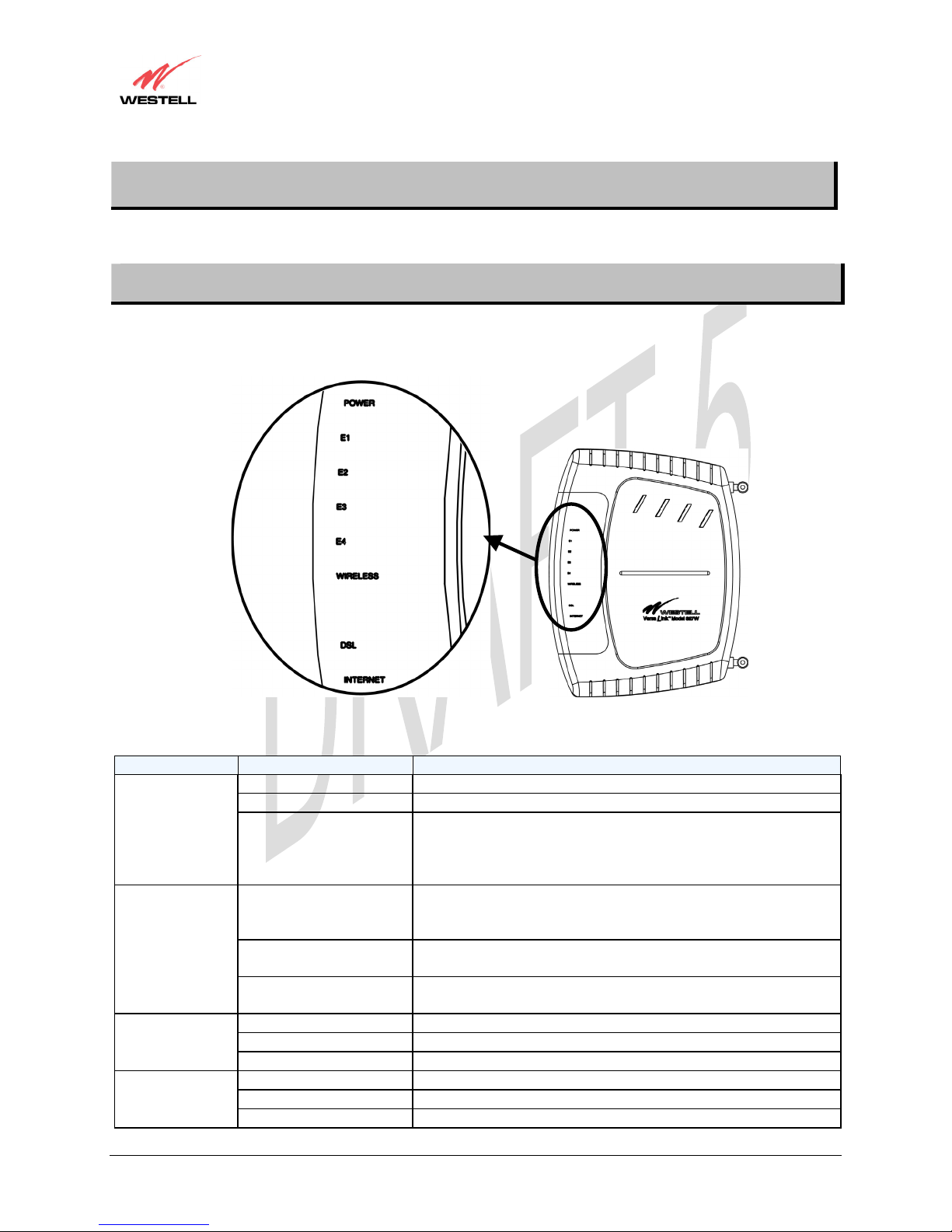
5.1 LED Indicators
The LED indicators are used to verify the unit’s operation and status. LED states are described in Table 1.
Table 1. LED States and Descriptions
LED State Description
Solid Green Power ON
No Light Power OFF
POWER
Flashing Red POST (power on self test) failure (not bootable), device
malfunction, or the modem is in safe boot mode.
Note: All other LEDs shall flash Green when the Power LED
flashes Red
Solid Green Powered device connected to the associated port (includes
devices with wake-on-lan capability where a slight voltage is
ETHERNET
(E1, E2, E3, E4)
Flashing Green LAN activity present (traffic in either direction) or when modem
supplied to an Ethernet connection)
is in safe boot mode
No Light Modem power OFF, no cable or no powered device is connected
to the associated port
Solid Green Link established.
WIRELESS
Flashing Green Wireless LAN activity is present (traffic in either direction)
No Light Modem power is OFF or No Link established.
Solid Green DSL good sync or when modem is in safe boot mode
DSL
Flashing Green DSL attempting sync
No Light Modem power Off or No Link
030-300452 Rev. A 6 March 2006
 Loading...