

Westell Interchange iQ 2000, Interchange iQ 2000plus User Manual
InterChange
iQ 2000 and iQ 2000plus
User Guide

Acknowledgements
Information in this document is subject to change without notice and does not represent a
commitment on the part of Westell Limited. The software may be used or copied only in
accordance with the terms of the purchase agreement. It is against the law to copy the software
on any medium except as specifically allowed in the purchase agreement. No part of this manual
may be reproduced or transmitted in any form or by any means, electronic or mechanical, including
photocopying or recording, for any purpose without the permission of Westell Limited.
Trademarks
Westell Limited recognises all third party trademarks.
Change History
Issue Product Status Date
010 Wes IiQ 2000 User Guide First Issue
020 Wes IiQ 2000 User Guide Phase 2 Dec 2000
030 Wes IiQ 2000 User Guide Frozen Apr 2001
040 Wes IiQ 2000 User Guide Restyle Mar 2002
050 Wes IiQ 2000 User Guide Update Jan 2003
060 IiQ 2000plus User Guide Revised Jun 2003
070 IiQ 2000plus User Guide Revised Nov 2004
Westell limited
Ringway House
Bell Road
Daneshill
Basingstoke
Hampshire, RG24 8FB
United Kingdom
Tel: +44 (0) 1256 843311
Fax: +44 (0) 1256 840429
email: info@westell.co.uk
www.westell.co.uk
© Copyright 2003, 2004 Westell limited
All rights reserved
Document number: UM 380 03 010

UM380 03 010 iii
User Guide
Contents
Acknowledgements 2
Trademarks 2
Change History 2
Preface 1
Scope of this Guide 1
Management 1
Vision iQ 2
1 Introduction 3
1.1 InterChange iQ 2000 3
1.2 InterChange iQ 2000plus 4
1.3 Management with Vision iQ 4
1.4 Environment 5
1.4.1 External Dimensions and Weight 5
1.4.2 Power Requirement 5
1.5 Approvals and Safety 5
2 Hardware Installation Procedure 6
2.1 Introduction to Unit Installation 6
2.2 Unit Installation 6
2.2.1 Unpacking and Inspection 6
2.2.2 Hardware Installation 7
Back Panel Equipment 7
2.3 Power-On and Self-Test 9
2.3.1 Terminal Connections 9
2.3.2 Self-Test 9
2.4 Vision iQ Management Software Installation 10
2.5 InterChange iQ 2000 and 2000plus Installation 10
2.5.1 Set Factory Default Values 11
2.5.2 Set Time and Date 11
2.5.3 Protocol Configuration 12
2.5.4 Configuration using the Quick Start wizard 13
2.5.5 Configuration changes (for manual changes to the default settings) 13
2.6 Cabling into a Management System 14
2.6.1 Alarm Signal Cabling 14
2.6.2 Alarm Signal Cable Test 14
2.6.3 Management Terminal Cabling 14
2.6.4 Management Terminal Cable Connection Test 14
2.7 Network Cabling 15
2.7.1 Port Usage 15
2.7.2 Cabling Practice 15
2.7.3 Cabling Procedure 15

iv UM380 03 010
InterChange iQ 2000 and iQ 2000plus
3 Switches and LEDs 17
3.1 Switches 17
3.1.1 Power ON/OFF switch 17
3.1.2 Sync switch 17
3.1.3 Port Impedance switches 17
3.2 Front Panel LEDs 17
3.2.1 Status LEDs 17
3.2.2 LAN LEDs 18
3.2.3 Port LEDs 18
3.2.4 Power LED 18
4 Management using Vision iQ 19
4.1 Configuration 19
4.2 Upgrade Configuration Procedure 19
4.3 Software Components 19
4.4 PC to InterChange Connection 19
4.4.1 Serial Link 19
4.4.2 Ethernet Connection 20
4.4.3 PC Specification 20
4.5 Software Installation 20
4.6 Configuring Vision iQ for use with InterChange iQ 2000 units 21
4.6.1 Starting Vision iQ 21
4.6.2 Working with Vision iQ 21
4.6.3 Vision iQ Mode Options 22
4.7 Connect 23
4.7.1 Connection 23
4.7.2 Disconnect 24
4.7.3 Reconnect 24
4.7.4 Shelf Definitions 24
4.7.5 Shelf Properties Group 25
4.7.6 Shelf Definitions Present Group 25
4.7.7 Define Poll List 27
4.7.8 Global Poll 28
4.8 Diagnostics 29
4.8.1 Diagnostics Overview 29
4.8.2 System Page 30
4.8.3 Module Page 30
4.8.4 Hardware Page 31
4.9 Major Alarms 31
4.10 Port Errors 32
4.11 Call Statistics 33
4.12 Loopback 34
4.13 Using the Configuration Wizard 34
4.14 InterChange iQ 2000plus Enhancements 43
4.14.1 Proxy Diversion 43
4.14.2 Redirection Timeout 43
4.14.3 Q.932 Redirecting Number Information 44
4.14.4 CCM Message Waiting Indication 44
4.14.5 Configuration Wizard Variation 44

UM380 03 010 v
User Guide
5 Conversions and Transparency 45
5.1 Q.931/DPNSS Conversion 45
5.1.1 Default Configuration 45
5.1.2 Configuration Options 45
5.2 Transparent Signalling 47
5.2.1 Overview 47
5.2.2 Supported Services 47
5.3 Interworking Between DPNSS & QSIG Equipment 48
5.4 IiQ 2000plus Proxy Interworking Between DPNSS & Q.931 49
5.5 Interworking DPNSS with Cisco Call Manager 50
6 Manual Configuration or Upgrade of Software
Protocol Options 52
6.1 General Module Configuration Procedure 52
6.1.1 The Configuration Menu System 52
6.1.2 Menu Help Facilities 52
6.1.3 Confirming Configuration Changes 52
6.2 Manual Configuration and Upgrade Options 53
6.2.1 Resource Manager Configuration (MGMT) 53
6.2.2 Channel 0 Configuration (CZ) - Delay Timers 53
6.3 Q.931/DPNSS Conversion Configuration 54
6.3.1 Port 1 (Q.931 port) Configuration 54
6.3.2 Port 2 (DPNSS port) Configuration 55
6.4 DPNSS/QSIG Transparency Options Configuration 57
6.4.1 DPNSS/QSIG Transparency 57
6.5 Advanced Service Interworking 58
6.5.1 DPNSS Message Waiting Implementations 58
6.5.2 ISDX Voice Messaging Systems 59
6.5.3 Name Mapping 59
6.5.4 Route Optimisation Options 60
6.5.5 QSIG Facility Element Encoding 60
6.5.6 QSIG Diversion Restriction 61
6.6 Configuring InterChange iQ 2000plus Proxy Services 63
6.6.1 Proxy Diversion Address Filtering 63
6.6.2 Operator Redirection 64
6.6.3 Service Spoofing 64
7 Problem Determination 65
7.1 Introduction 65
7.2 Power-On Problems 65
7.3 Operational Problems 66
7.4 Diagnostic Procedures 68
7.4.1 Power Supply 68
7.4.2 Self Test Failure 68
7.4.3 Port Failure Alarm 68
7.4.4 Checking Cables 69
7.4.5 Loop-Back Testing 70
7.4.6 Call Failures 70
7.4.7 Fatal Errors 71
7.4.8 Event Reporting 72
7.4.9 SNMP Traps 72
7.4.10 Call Tracing 73

vi UM380 03 010
InterChange iQ 2000 and iQ 2000plus
8 DPNSS Compliance Tables 74
8.1 Basic Call 74
8.2 Data Call 74
8.3 Executive Intrusion (Partial Support) 75
8.4 Diversion 76
8.4.1 Diversion - Immediate 76
8.4.2 Diversion - On Busy 78
8.4.3 Diversion - On-No-Reply 79
8.5 Hold 80
8.6 Three Party 81
8.7 Call Offer 82
8.8 Service Independent Strings 82
8.9 Bearer Service Selection 83
8.10 Route Optimisation 83
8.11 Redirection 84
8.12 Centralised Operator 86
8.13 Add-On Conference 88
8.14 Do Not Disturb 89
8.15 Loop Avoidance 89
8.16 Network Address Extension 90
Appendices
A Approvals, Safety Instructions and Statutory Information 91
B References & Technical Specifications 98
C Cabling Specifications 102
D Glossary of Terms 104

UM380 03 010 1
User Guide
Preface
Scope of this Guide
This Guide describes the hardware and software of the Vision iQ managed InterChange
iQ 2000 and iQ 2000plus products, the installation, maintenance and general operation.
The Guide is divided into the following sections:
Chapter 1 Introduction.
Chapter 2 Hardware Installation Procedure.
Chapter 3 Switches and LEDs.
Chapter 4 Management using Vision iQ.
Chapter 5 Conversions and Transparency.
Chapter 6 Manual Configuration or Upgrade of Software Protocol Options.
Chapter 7 Problem Determination.
Chapter 8 DPNSS Compliance Tables.
Appendices
A Approvals,Safety Instructions and Statutory Information
B References and Technical Specifications
C Cabling Specifications
D Glossary of Terms
Management
InterChange iQ 2000 products are designed for years of error-free running with little, or no,
requirement for management involvement once initial set-up is complete. Normally
any network faults are notified and diagnosed from alarms provided by the attached
equipment, after interaction with the InterChange unit, and it is superfluous and confusing to
network operations staff to have these indications repeated at a second interface.
For the rare cases where installation philosophy requires direct notification of alarms,
InterChange iQ 2000 and iQ 2000plus have four types of management interface:
• LEDs,
• A relay which can make or break an alarm circuit in the event of a major hardware
related failure,
• An RS-232 serial interface which can be used for fault diagnosis and configuration
management, either from a locally connected PC running Vision iQ, or from a
remote PC via a modem link, and
• Ethernet.
These interfaces operate concurrently and quite independently.

2 UM380 03 010
InterChange iQ 2000 and iQ 2000plus
Vision iQ
Vision iQ is a Windows application for managing the InterChange iQ 2000 and iQ 2000plus.
Vision iQ is used to download protocol conversion software to the InterChange unit from a PC,
using the Download utility. The product is configured using the Vision iQ application described in
this manual. Vision iQ also manages the operational, diagnostic and alarm information for each
port used in the conversion or channel grouping.
Vision iQ identifies the software and hardware facilities available on an InterChange unit and
displays parts or all of the configuration and management dialogues accordingly.

UM380 03 010 3
Introduction
1 Introduction
1.1 InterChange iQ 2000
InterChange iQ 2000 is a dual port ISDN unit designed to perform signalling and service
reconciliation between two unlike ISDN signalling systems.
It is typically deployed to attach:
• a QSIG (or DPNSS) PBX to a DPNSS (or QSIG) network, or
• a number of DPNSS PBXs to a QSIG or Q.931 backbone (e.g. VoIP or ATM)
network, or
• a DPNSS PBX to a Q.931-based Public ISDN service (such as ‘ISDN 30e’).
When attaching a QSIG (or DPNSS) PBX to a DPNSS (or QSIG) network,
InterChange iQ 2000 provides seamless service interworking between the attached PBX and
other PBXs in the network, including inter-operation of most of the commonly used services.
InterChange iQ 2000 facilitates basic call interworking, including simple services such as
calling and connected identity when attaching a number of DPNSS PBXs to a QSIG or Q.931
backbone network, or a DPNSS PBX to a Q.931-based Public ISDN service.
In addition, when attaching a number of DPNSS PBXs to a QSIG or Q.931 backbone
network and the core network supports QSIG signalling, InterChange iQ 2000 can transport
DPNSS signalling across the network and deliver it practically transparently via a similar
InterChange unit to a remote DPNSS PBX. In this mode all DPNSS Supplementary Services
are supported apart from some link-specific Traffic Channel maintenance services.
InterChange iQ 2000 supports 2 E1
Primary Rate [2 Mbit/s (30B + D) Common Channel
Signalling] interfaces; providing a single Primary Rate conversion. It
is a portable unit that can
be mounted on a desk. A kit of brackets is also available to allow the unit to be installed on a 19
inch rack. It is particularly suited for use in Customer Premises Environments (CPE) to interface
equipment into Virtual Private Networks.
Figure 1: InterChange iQ 2000 in a Private Network.
4 UM380 03 010
InterChange iQ 2000 and iQ 2000plus
Figure 1 shows DPNSS PBXs interconnected across a QSIG network. In this configuration,
the combination of InterChange units and the network behave as a single DPNSS transit
node and transports DPNSS supplementary signalling.
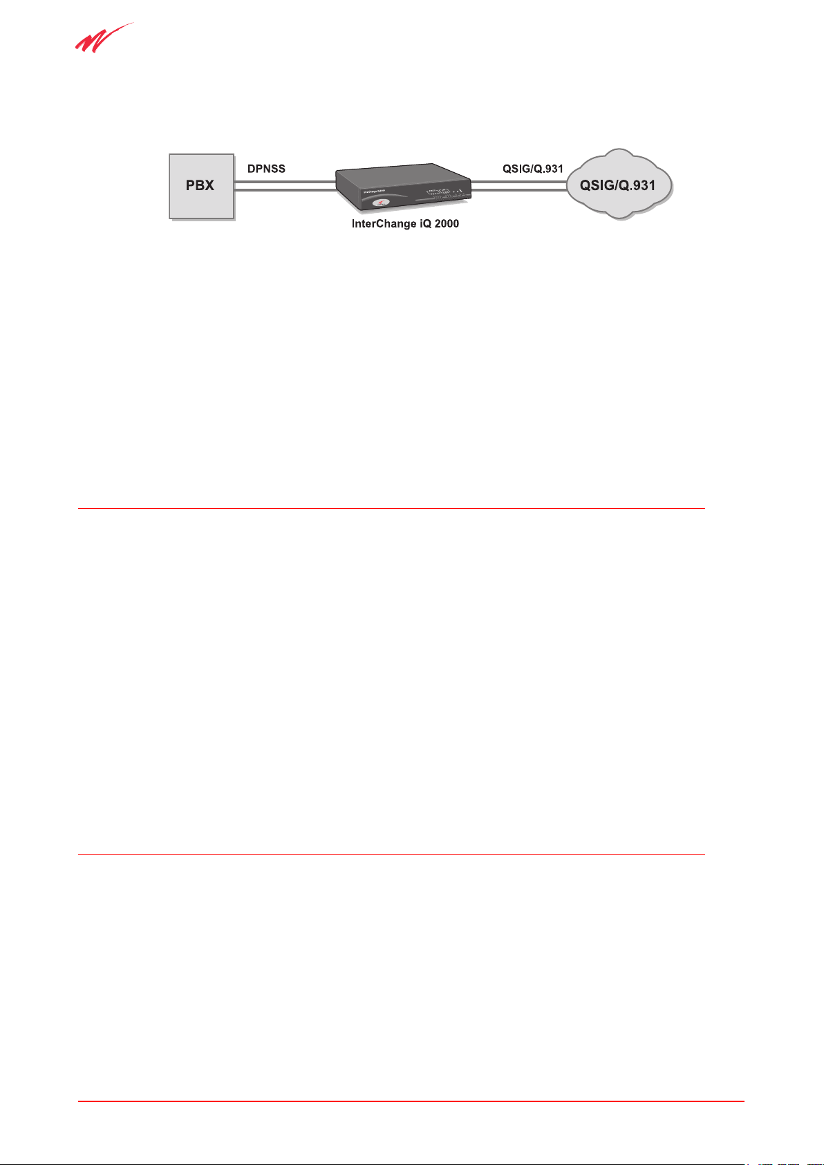
Figure 2: InterChange iQ 2000 in a CPE.
Figure 2 shows an InterChange iQ 2000 interfacing a PBX using the UK standard DPNSS
protocol to the QSIG/Q.931 protocol.
Conversions operate on the common signalling channel only. Bearer circuits are passed directly
through the unit. Each protocol support is configurable to meet specific application needs.
The Virtual Private Network protocol support can be configured to operate into sub-equipped
ISDN trunks, allowing the user to maximise the benefits of the advantageous Primary Rate
ISDN tariffs now being offered by some PTOs.
1.2 InterChange iQ 2000plus
The IiQ 2000plus is a variation of the InterChange iQ 2000 providing some additional
facilities:
• The ability to perform diversions on behalf of the PBX; and
• Support for the Q.932 ‘redirecting number’ element for diversion;
• Advanced Wizard custom configuration for Cisco Call Manager;
• The ability to display DPNSS Message Waiting Indications on telephones
controlled by Cisco Call Manager.
If a unit is first installed with version R.2.1.0 of the operating software, an IiQ 2000 may be
upgraded to an IiQ 2000plus. For more information on the upgrade, contact your distributor /
reseller or Westell Account Manager.
1.3 Management with Vision iQ
Vision iQ, the Management Interface, provides the facilities to connect (locally or remotely) to an
InterChange iQ 2000 or iQ 2000plus, display diagnostic information and configure the unit.
Vision iQ allows you to:
• connect and disconnect from the management terminal,
• set up a definition for the InterChange iQ 2000 or iQ 2000plus unit,

UM380 03 010 5
Introduction
• display diagnostic information which includes:
- impedance settings,
- Port Error, Major Alarm and call statistics,
• Global polling of a list of remote InterChange iQ 2000 and iQ 2000plus units,
• configure the InterChange iQ 2000 or iQ 2000plus unit, and
• enable SNMP traps to up to 8 recipients.
New applications or updates are loaded into the InterChange iQ 2000 and iQ 2000plus unit’s
flash memory using the Download facility in Vision iQ.
1.4 Environment
Both InterChange iQ 2000 and iQ 2000plus units can be mounted in a cabinet or installed
free standing and should be sited to allow free movement of air for cooling purposes.
1.4.1 External Dimensions and Weight
Unpacked InterChange iQ 2000 and iQ 2000plus units are 275 mm wide x 217 mm deep x
50 mm high, and weigh 1.4 Kg. All diagnostic indicators are visible at the front and
all cable access is at the rear.
1.4.2 Power Requirement
The operating input voltage range is 100 - 240 VAC (50-60 Hz) with a power consumption
of maximum 10W.
The fuse and the On/Off switch (single pole) are accessible from the rear of unit
1.5 Approvals and Safety
The InterChange iQ 2000 and iQ 2000plus are approved for connection to
telecommunications systems, subject to conditions set out in this User Guide.
All users of the product must make themselves familiar with the Safety Information
contained in Appendix A.
Users must also be aware of the approvals information in Appendix A and, for use in the
U.K, comply with the statutory requirements for connection to a Public Network, also
outlined in Appendix A.

6 UM380 03 010
InterChange iQ 2000 and iQ 2000plus
2 Hardware Installation Procedure
This chapter takes the suitably trained and qualified person through the process of:
• installing an InterChange iQ 2000 or iQ 2000plus unit,
• initial testing,
• cabling, and
• operational checks.
Warning:
Read the Safety Instructions in Appendix A before beginning installation. Installation
should only be carried out by a qualified trained Engineer.
Installation can begin when the site has been correctly prepared.
2.1 Introduction to Unit Installation
To install an InterChange iQ 2000 or iQ 2000plus unit, carry out the following tasks in order:
• Unpacking and Inspection
• Hardware Installation
• Power-On and Self-test
• Configuration
• Operational Checks
• Cabling to the Network
2.2 Unit Installation
2.2.1 Unpacking and Inspection
The InterChange iQ 2000 is supplied in a single package containing the following:
• An InterChange iQ 2000 or iQ 2000plus unit.
• Mains cable.
• Management cable.
• 120 Ohm crossover cable (for use in Cisco networks).
• Safety Guide with Approvals, Safety Instructions and Statutory Information.
• Hard Copy Quick Start Guide.
• CD with Vision iQ and Protocol Application Software, User Guide and
Quick Start Guide.
UM380 03 010 7
Hardware Installation Procedure
The packaging is externally labelled with the order code and contents. Check this against
the order form and packing slip to make sure that the correct system type has been received.
Return the unit if there is any discrepancy.
Save the packaging material and store it in a clean, dry area for re-use if the equipment is to
be moved.
2.2.2 Hardware Installation
Note: There is no physical difference between the InterChange iQ 2000 unit and the iQ
2000plus unit.
InterChange iQ 2000
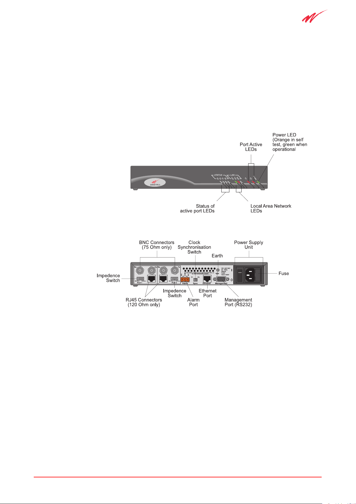
Figure 3: Front View of an Interchange iQ 2000 unit.
Figure 4: Rear View of an InterChange iQ 2000 unit.
Back Panel Equipment
• Impedance Switch - Refer to Section 3.1.3
• BNC Connectors - Refer to Section 2.6
• RJ45 Connectors - Refer to Section 2.6
• Alarm Port - Refer to Appendix B.9
• Clock Synchronisation Switch - Refer to Section 3.1.2
• Ethernet Port - Refer to 2.6.3
• Management Port - Refer to section 4
• Power Supply Unit - Refer to section 1.3.2
8 UM380 03 010
InterChange iQ 2000 and iQ 2000plus
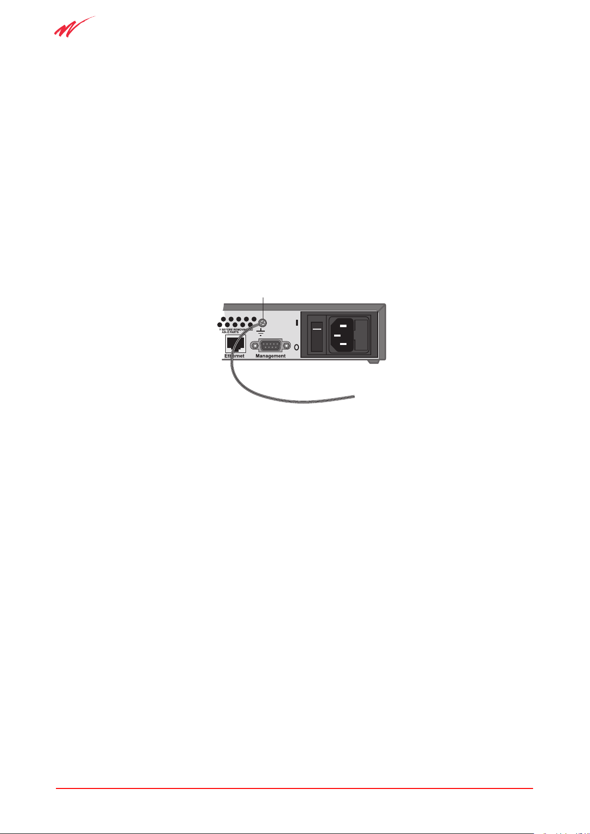
Caution:
The Interchange iQ 2000 and iQ 2000plus must be earthed at all times via the protective
earth terminal on the rear of the unit.
The earthing cable must conform to the following specification. It shall:
• be PVC covered green with yellow longitudinal coloured stripes as defined in
EN 60950,
• be rated at 17 amps,
• have a cross sectional area of 1.5mm2,
• be of stranded wire 7/0.53, and
• be terminated with an M3 ring terminal 1-2.6 mm2 conductor.
100 -240 VAC
50 - 60H
z
350mA
FUSE
T2A H 250V
Protective Earth
Figure 5: View showing earth screw on the rear panel.
Location of Unit
Make sure that there is free flow of air between the base of the unit and the surface on which
it is installed.
Connecting to Power
Make sure the mains switch on the mains inlet panel at the rear of the unit is set to the
OFF (O) position.
Use the power cable provided to connect between the mains inlet and the designated line
distribution socket.

UM380 03 010 9
Hardware Installation Procedure
2.3 Power-On and Self-Test
2.3.1 Terminal Connections
To run installation and configuration software, access via a PC with Vision iQ is required. A
terminal can also be used as a monitor while the self-test software is running.
On the rear panel of the unit is a 9-way D type connector marked Management, as shown
in Figure 4. To connect a PC, refer to the cabling and communications specifications in
Appendix C.
1 Make sure that no ISDN cables are connected to the rear of the unit.
2 Make sure electrical power is available and set the unit mains switch (located on
the rear panel at the right of the unit) to ON (I).
3 Check that the Power LED comes on ORANGE. This is the right-hand LED on the
front panel, shown in Figure 3.
2.3.2 Self-Test
When power is first applied, the Power LED on the front panel comes on ORANGE and the
four STATUS LEDs come on and go off in sequence (from left to right) to indicate the unit is
performing the Self-Test. This is a sequence of tests (stored in the Boot Flash) which check
correct operation of the hardware functions. Allow this to run to completion. The Self-Test
should complete in less than one minute.
Successful Self-Test
When all the tests have completed successfully, the Self -Test Module invokes the Loader
module. The Power LED changes colour from ORANGE to GREEN.
Self-Test Failure
If any test in the sequence fails then the cycle of the STATUS LEDs will stop (with one LED
remaining on) and the Power LED will remain ORANGE.
At the end of the test sequence, the self-test software does not pass control on to the
operational software. At a 30 second repeat interval the terminal (if connected) receives
a summary of all errors found during the self-test. The self-test will attempt to re-run
approximately every five minutes. This is done to guard against any transitory problems.
When an error is indicated consult Chapter 7 Problem Determination, for the appropriate
corrective action.
Once errors have been corrected make sure the self-test runs satisfactorily
to completion. Only proceed when self-test passes. InterChange iQ 2000 and iQ 2000plus
are made to reset and re-run its self-test by setting the power switch on the rear of the unit to
OFF (O) then setting it to ON (I).
When self-test has been completed correctly you may proceed to perform configuration and
the operational checks.

10 UM380 03 010
InterChange iQ 2000 and iQ 2000plus
2.4 Vision iQ Management Software Installation
Note:
Windows® NT users must have administrator user rights to install Vision iQ.
Follow this procedure to install Vision iQ:
1 Start Windows® on the PC and insert the CD-ROM in the reader.
The CD-ROM will automatically launch a main menu on the screen.
2 Choose Install Vision iQ from the list.
The install wizard will appear and enable Vision iQ to be installed to the hard disk
of the PC. Once installed, an icon will be placed on the Windows® desktop and
Vision iQ placed in the Windows® desktop Startup Program option.
Note:
The Vision iQ password is reset to its default state by the installation process. The default
password is: Vision and is case sensitive.
2.5 InterChange iQ 2000 and 2000plus Installation
This procedure installs the initial configuration for the unit and checks that the operational
software is operating correctly.
On completion of the self-test the Loader Module is invoked. It consists of:
• an Application Flash Check module, and
• a Download module.
The Application Flash Check module checks the Application Flash for the presence of a
Protocol Application Module.
If a Protocol Application Module is present in the Application Flash it is copied into DRAM
and executed.
If a Protocol Application Module is not present, the Download module is copied into DRAM and
executed. The protocol application software must then be downloaded before proceeding.
The Protocol Application Module consists of:
• A Configuration module
• An Operation module comprising:
- A Protocol module
- An Online Management module

UM380 03 010 11
Hardware Installation Procedure
You have to enter a number of commands to configure the unit. In the examples that follow,
InterChange iQ 2000 output is shown indented, your required inputs are highlighted. At the
end of each input press <Enter>.
Further information on using the configuration system is contained in Section 6.2. First:
1 Make sure no ISDN cables are connected to the unit.
2 Make sure the unit is powered on and self-test has completed successfully.
3 Connect the PC to the Management port and run Vision iQ.
To enter Vision iQ and the Configuration Wizard, refer to Section 4.6 Configuring Vision iQ
for use with InterChange iQ 2000 units .
2.5.1 Set Factory Default Values
Set the configuration to the factory default values. Type:
Select Configuration Option? RSET <Enter>
The factory default values are reset. The following message is re-displayed:
Select Configuration Option?
2.5.2 Set Time and Date
Set the correct time and date by entering the following sequence:
Select configuration option ? TIME <Enter>
Configure Time and Date
Time Configuration option? TIME <Enter>
You are prompted to enter the date and time. Follow the prompts and enter appropriately. Set
the seconds value a little into the future as the time is not set immediately. When complete,
the following is displayed:
Time Configuration option?
To check your input, type:
Time Configuration option? VIEW <Enter>
The time and date is displayed.
Save the new time and date information to the battery-backed clock. Type:
Time Configuration option? SET <Enter>
Exit from this menu. Type:
Time Configuration option? EXIT <Enter>

12 UM380 03 010
InterChange iQ 2000 and iQ 2000plus
You are returned to the higher menu level.
The default values and correct time and date are now set and you are ready to proceed with
protocol configuration.
2.5.3 Protocol Configuration
The menu displays:
Select Configuration Option?
To change the management connection from direct/remote via modem to ethernet, the user
needs to configure the InterChange iQ 2000 or iQ 2000plus Console. Type:
CONS <Enter>
The Configuration Wizard asks for the console parameter:
Configure which console parameter ?
To list the menu of available parameters, type:
? <Enter>
To display the present configuration, type:
DISP <Enter>
The present configuration is shown:
console is over serial
BAUD rate: 38400
Flow Control: XON/XOFF
To change the configuration, type:
CONF <Enter>
The Configuration Wizard asks:
Console type ?
Type:
ETH <Enter> for Ethernet or
SER for Serial
For Ethernet, the Configuration Wizard then asks:
IP address ?
This is an address for the unit, which the user must obtain and make a note of, from the
network administrator. The format of the address (and the default) is 0.0.0.0.

UM380 03 010 13
Hardware Installation Procedure
After typing in the address, the Configuration Wizard asks:
Subnet mask ?
Again, this is an address for the unit, which the user must obtain (and make a note of), from
the network administrator. The format of the address (and the default gateway) is 0.0.0.0.
After typing in the address, the Configuration Wizard asks:
Configure which console parameter ?
Type: EXIT <Enter>
This will return the user to the main configuration menu:
select Configure which configuration option ?
2.5.4 Configuration using the Quick Start wizard
To display the top-level menu, type:
? <Enter>
The Configuration Wizard then offers the user a choice of available configuration options.
To display the Quick Start menu, type:
QUICK <Enter>
This takes the user to the option menu for the Quick Start wizard and allows the user to set
up a basic configuration. Answer the questions as prompted.
For more information on the Configuration Wizard, see Section 4.13.
2.5.5 Configuration changes
(for manual changes to the default settings)
To set up an advanced configuration, at the top level menu, type:
Change the values in each menu where the default values are incorrect for your applications.
Further tips and details of use of this system are provided in the discussion in Section 6.2.
The menu leads you through the options. If you have no changes to make, skip to the next
step. To list the options available type:
? <Enter>
in response to any prompt.
To return to the level above, type:
EXIT <Enter>
ADV <Enter>.

14 UM380 03 010
InterChange iQ 2000 and iQ 2000plus
When you have completed the changes to the default parameters and are back to the top
level menu, type:
Select Configuration Option? EXIT <Enter>
The program exits from the menu, saves the new parameter settings into non-volatile
memory, then activates the operational code.
2.6 Cabling into a Management System
This section explains how to connect the InterChange iQ 2000 and iQ 2000plus into a
Management System via the alarm relay outputs.
2.6.1 Alarm Signal Cabling
Prepare and route an alarm cable to the left hand side of the cabinet (viewed from the rear)
(refer to Figure 4). Connect the cable to the 3-way Weidmuller ALARM connector at the rear
of the first InterChange iQ 2000 unit. Lock in place.
Connect the cable to an Alarm Panel or alarm signal detector at the remote end.
2.6.2 Alarm Signal Cable Test
Leave the unit powered on with no ISDN cables connected. This causes an alarm condition
which is notified by the alarm detection equipment.
If no alarm condition is notified then correct the cabling.
2.6.3 Management Terminal Cabling
InterChange iQ 2000 units are normally run with an in-situ management terminal. Where it
is required, route the prepared Management Terminal cable to the left hand side of the unit,
connect to the D-9 outlet labelled Management on the rear of the unit (refer to Figure 4), and
lock in place. If the InterChange iQ 2000 or iQ 2000plus is to be managed via the Ethernet,
the user should supply a suitable cable (cat. 5 UTP patch cable) with a RJ45 connector at
the InterChange iQ 2000 unit end for connection to the user Ethernet connection.
Connect the cable to a PC or to a remote PC via a modem or the Ethernet.
2.6.4 Management Terminal Cable Connection Test
Turn on the unit and the remote terminal. Make sure that the terminal communications
parameters are set up correctly, as specified in Appendix C. Let the self-tests complete and
the unit enter operation. From the management terminal, enter any management command
and check that the correct response is returned.
If the correct response is not returned then corre§ct the management cable.
Leave the unit switched on for the next test.

UM380 03 010 15
Hardware Installation Procedure
2.7 Network Cabling
This section explains how to connect an InterChange iQ 2000 unit into the ISDN.
Warning:
Before attaching ISDN cables, perform any power-on configuration which may
be required to make the signalling conversion fit the particular application. Failure to
do so may cause unexpected effects on the remote equipment when the InterChange
iQ 2000 unit is connected.
2.7.1 Port Usage
At the rear of the unit are two pairs of BNC connectors (75 Ohm) marked Rx and TX, and
two RJ45 connectors (120 Ohm). There is a switch marked 75 Ohm and 120 Ohm for
changing between the connectors. PORT 1 and PORT 2 are indicated on the rear.
Port 1 presents a Q931 Protocol variant and Port 2 presents DPNSS. The exact parameters
of each protocol are configured through the off-line menus.
The sense of each connection can be changed by configuration.
2.7.2 Cabling Practice
Specimen drawings for BNC and RJ45 plug terminations will be provided on request.
Label all cables, especially 75 Ohm coax pairs, during installation. Labelling greatly eases
any trouble shooting or subsequent reconnection/re-configuration of the units.
Attach the label to each cable in an easy to read location indicating the InterChange
equipment (if there is more than one), the port it connects and its direction. For example:
1/1 TX (Q.931)
1/1 RX (Q.931)
1/2 TX (DPNSS)
1/2 RX DPNSS)
Depending on the installation, labelling may be beneficial at either or both ends of
each cable.
2.7.3 Cabling Procedure
Connect to the appropriate connectors at the rear of the unit.
When connecting cables to a live unit, connect the pair of cables attaching to Customer
Premises Equipment (CPE, e.g. PBX) before connecting to the remote network, particularly if
this is a public service network.
Cable continuity can be checked by applying a physical loop, TX to RX, at the attached
equipment.

16 UM380 03 010
InterChange iQ 2000 and iQ 2000plus
Warning:
When applying loopbacks, assert the public network loop before the private
equipment loop, and remove the loops in reverse order. Failure to observe this
precaution may lead to excessive port error reports and the link being put spuriously
out of service.
Remove the loopbacks (see the notes above on the order of removal) and connect to the
remote equipment.
Network cabling is now complete.

UM380 03 010 17
Switches and LEDs
3 Switches and LEDs
This chapter describes:
• Operation of the switches on the rear panel
• The information provided by the LEDs on the unit front panel
During normal operation of the unit the LEDs indicate its operational status. This information
is particularly useful in diagnosing cabling faults and external equipment problems, during
both installation and normal running.
3.1 Switches
3.1.1 Power ON/OFF switch
The power ON/OFF switch is located on the rear panel adjacent to the mains connector. It
switches mains electricity to the Universal Input Power Supply Unit.
3.1.2 Sync switch
The Sync switch allows the unit clock source to be synchronised to either of the primary
ports (P1 or P2). It is located on the rear panel between the Alarm connector and the
Ethernet connector. The selection must be made before power is applied to the unit.
Ideally, the Sync switch should be set to whichever port is connected to the network so that the
unit is synchronised with a central clock source rather than the clock source of another unit.
However, in a Packet Switched Network the synchronisation should come from the PBX.
3.1.3 Port Impedance switches
The Port 1 and Port 2 impedance switches allow the selection of either 75W or 120W
impedance to be made. They are located adjacent to the Port 1 and Port 2 connectors on
the rear panel. The selection should be made before power is applied to the unit.
3.2 Front Panel LEDs
The unit has 10 LEDs on its front panel. During the self test sequence, and in the event of an
alarm, they show unit status information.
3.2.1 Status LEDs
There are 4 red Status LEDs; S3,S2,S1 and S0. They indicate unit status in conjunction with
the two port LEDs, P1 and P2. During unit self-test, the status LEDs will come on and go off
in sequence and in the event of a self-test failure, stop with one LED remaining on.

18 UM380 03 010
InterChange iQ 2000 and iQ 2000plus
3.2.2 LAN LEDs
Three LEDs indicate LAN activity. A red TxD LED comes on when if data is being
transmitted; A red RxD LED comes on if data is being received and a green Link LED comes
on if the connection is OK. If Ethernet is not connected, these LEDs will be off.
Note:
The RxD LED will flash for any data on the Ethernet, regardless of destination.
3.2.3 Port LEDs
There are two red Port LEDs, P1 and P2. Together with the Status LEDs, they indicate unit
status. When the unit is operating correctly, these LEDs ripple, with all status LEDs off.
When a problem exists, the Port LEDs will show its location (P1 or P2, or if both P1 and P2
are lit, a major alarm exists). The status LEDs will then indicate the problem (refer to 7.4.3).
If more than one has a problem, they will be shown in a cycle of five seconds each.
3.2.4 Power LED
The Power LED has two functions. When power is applied, it comes on orange to indicate
the unit is in self-test mode. When the self-test has been satisfactorily completed, it changes
to green to indicate the unit is functioning correctly.

UM380 03 010 19
Management using Vision iQ
4 Management using Vision iQ
4.1 Configuration
The InterChange iQ 2000 and iQ 2000plus units are managed locally, via modem or via the
Ethernet using the management ports and Vision iQ. The ports are situated on the back of
the unit.
Vision iQ runs on an attached PC and provides the features to:
• transfer applications into the FLASH memory in the InterChange iQ 2000 unit, and
• configure and monitor the application.
4.2 Upgrade Configuration Procedure
This is a quick guide to installing the upgrade protocol software that allows you to connect
to and configure an InterChange iQ 2000 or iQ 2000plus. The procedure is only required for
upgrades to the InterChange iQ 2000 or iQ 2000plus unit:
1 Install the Vision iQ software on your PC.
2 Connect your host PC to the InterChange iQ 2000 unit, using a modem link or
Ethernet connection if working remotely, or a serial link if working locally.
3 Run Vision iQ to:
• install the InterChange iQ software on the InterChange unit, using the Download
application, and
• configure the application.
4.3 Software Components
An InterChange iQ 2000 unit requires the following:
• Vision iQ software (run on the attached PC).
• Application software (run on the InterChange iQ 2000).
• The Vision iQ User Guide (supplied on CD-ROM).
4.4 PC to InterChange Connection
4.4.1 Serial Link
For local access, connect your PC to the InterChange iQ 2000 or iQ 2000plus unit. Attach
one end of the management cable to one of the serial ports at the rear of your PC, attach the
other end to the Management Port on the InterChange iQ 2000 or iQ 2000plus unit.

20 UM380 03 010
InterChange iQ 2000 and 2000plus
4.4.2 Ethernet Connection
For remote access via the Ethernet, a RJ45 connector is provided on the back of the
InterChange iQ 2000 unit. This allows connections over TCP/IP (Winsock 2) working over a
LAN, WAN and the Internet.
4.4.3 PC Specification
Your PC must be an IBM compatible computer with, as a minimum:
• Pentium 166 processor (Pentium II 450 MHz minimum for call trace),
• 32 Mb of main memory (64 Mb for Windows® NT),
• 200 Mb hard disc,
• A colour S-VGA monitor (screen resolutions of 800 x 600),
• A mouse or other pointing device,
• Keyboard standard or enhanced,
• 3.5 inch disk drive,
• CD-ROM drive,
• At least one free serial port or an internal modem card, and
• Microsoft Windows® 95/98 or NT 4.
4.5 Software Installation
Note:
Windows® NT users must have administrator user rights to install Vision iQ.
Follow this procedure to install Vision iQ:
1 Start Windows® on the PC and insert the CD-ROM in the reader.
The CD-ROM will automatically launch a main menu on the screen.
2 Choose ‘Install Vision iQ’ from the list.
The install wizard will appear and enable Vision iQ to be installed to the hard disk of
the PC. Once installed, an icon will be placed on the Windows® desktop and Vision
iQ placed in the Windows® desktop Startup Program option.
Note:
The Vision iQ password is reset to its default state by the installation process. The default
password is:
Vision
and is case sensitive.

UM380 03 010 21
Management using Vision iQ
4.6 Configuring Vision iQ
for use with InterChange iQ 2000 units
4.6.1 Starting Vision iQ
Double click the Vision iQ icon or select Vision iQ from the Windows® desktop Startup Program
option. Vision iQ briefly displays its title dialogue and then displays the main window:
Figure 6: The Vision iQ Main Window.
The main window contains eight menu options:
• Mode • Control
• Connect • Special
• Diagnostics • Web
• Configuration • User Guide
4.6.2 Working with Vision iQ
To start working with Vision iQ use the Connect option to connect to the InterChange unit.
Once connected you can choose to monitor the unit activity or configure the ports to
your requirements.
To monitor the unit activity, enter the Mode option and select Monitor Mode. This is the
default mode when Vision iQ is run and does not allow any configuration of the shelf to
be undertaken.
To configure the unit, enter the Mode option and select Configuration Mode, which is
password protected.
Use the Special, Password option to change the password. The user should make a note
of any new password. The default password is Vision, which is case sensitive. Enter the
password and press OK. The configuration icons become un-greyed.
22 UM380 03 010
InterChange iQ 2000 and 2000plus
You are now ready to use Vision iQ to download application software to your InterChange iQ
2000 or iQ 2000plus unit and to manage its configuration.
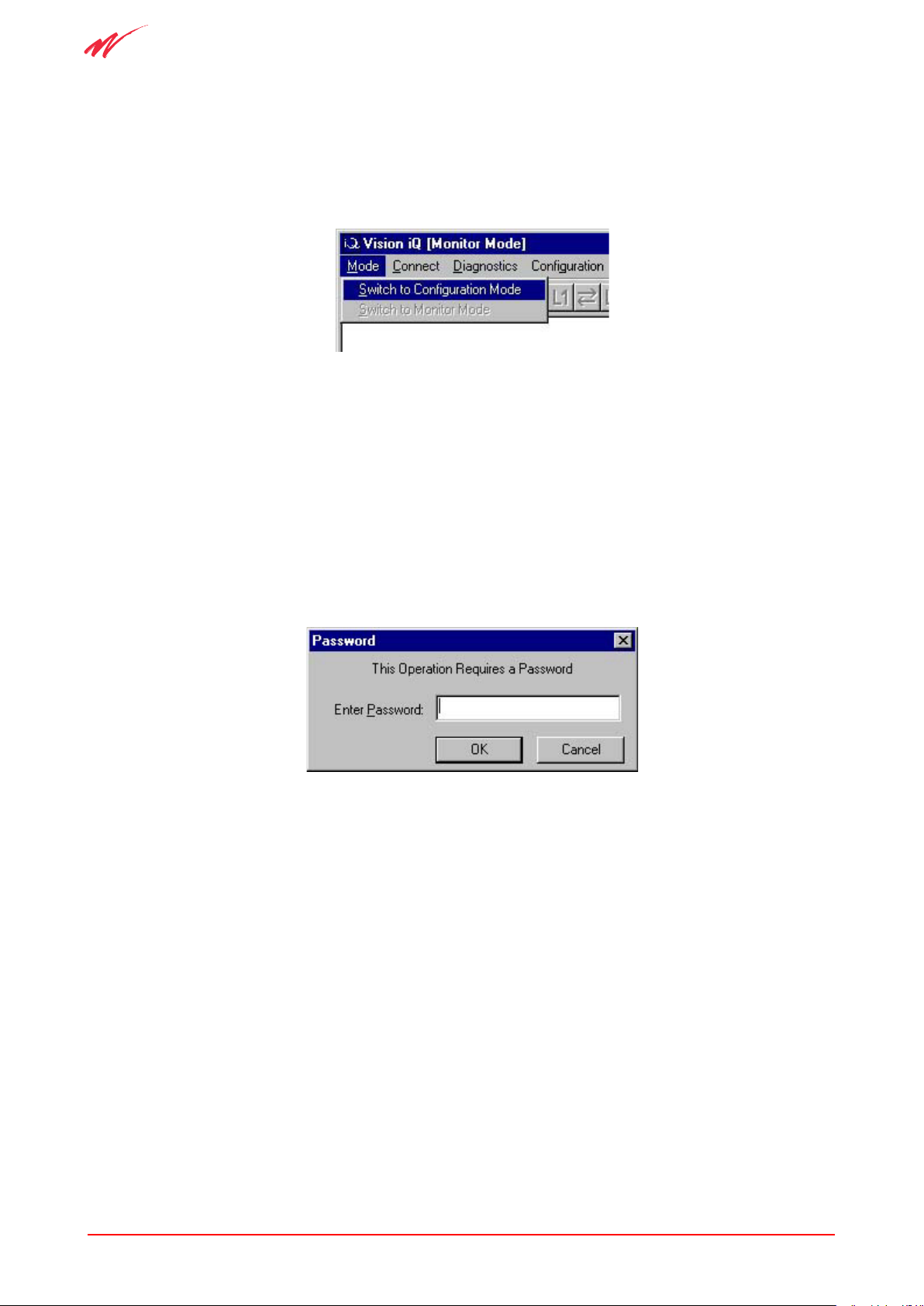
4.6.3 Vision iQ Mode Options
The Mode menu contains two options:
Figure 7: Vision iQ Mode Options.
Switch to Configuration Mode (Figure 7) which allows full configuration and monitoring
facilities. Configuration mode is normally password protected.
Switch to Monitor Mode which allows access to a number of functions in read-only mode.
This is the default mode when Vision iQ is first installed.
Configuration Mode
Select Switch to Configuration Mode. You are asked to enter your password.
Figure 8: Password Dialogue Box.
You are strongly recommended to change your password immediately after installing Vision
iQ. If the password is lost the only way to regain access to Vision iQ configuration facilities, is
to re-install Vision iQ.
The configuration mode allows you to set up and access shelf definitions, do global polls and
access the configuration Wizard.
Monitor Mode
Monitor mode allows you monitor the status of the shelf but not to change any of the
configuration. There is no password protection of this mode.
The available monitoring options available to you are:
• Connect - Disconnect and Reconnect.
• Diagnostics - Overview, Major Alarms, Port Errors and Call Statistics.
UM380 03 010 23
Management using Vision iQ
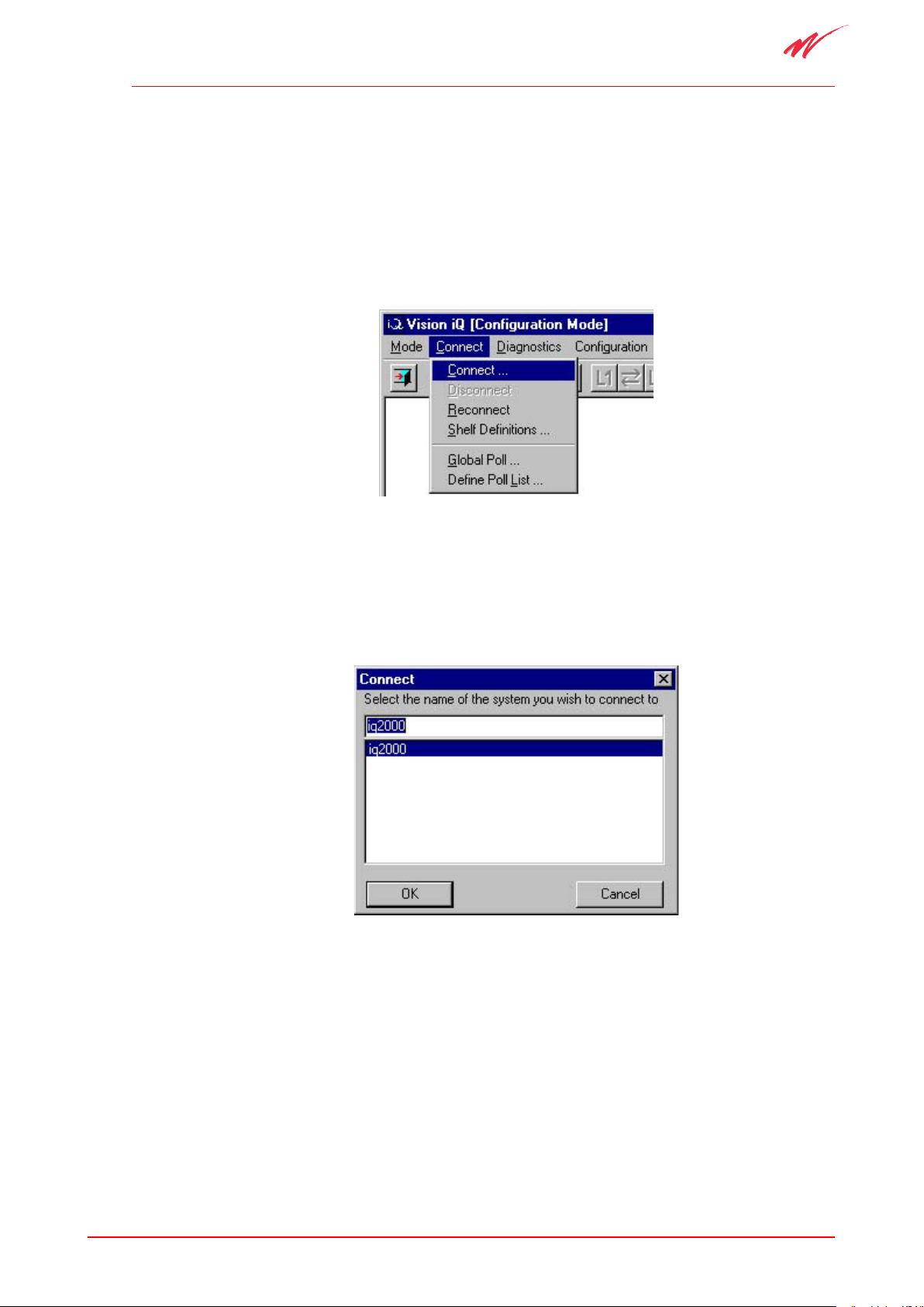
4.7 Connect
Note:
Although the InterChange iQ 2000 is a self contained unit, during configuration, it is referred
to as a ‘shelf’.
The Connect menu allows you to connect to an InterChange iQ 2000, disconnect from and
reconnect, and create and modify shelf definitions.
Figure 9: The Vision iQ Connect Menu.
4.7.1 Connection
Choose Connect or Reconnect to connect to one of the predefined target Interchange iQ
systems. Reconnect re-establishes contact with the last target system connected to by Vision iQ
Figure 10: Vision iQ Connect Menu.
From the pull down menu (Figure 10), select the system required for connection to and press
OK or double click. Vision iQ connects to the target system.
If an invalid shelf name is selected, the user is informed and the connection process
terminates. Restart the connection and use the correct shelf name.
A connecting dialogue is displayed, showing the status as the connection proceeds. This is
particularly useful when connecting remotely via a modem. Any modem failure is reported
during this procedure. When connected, the Vision iQ title bar changes to show the title of
the selected shelf definition. The icon buttons are enabled.
24 UM380 03 010
InterChange iQ 2000 and 2000plus
The Connect and Shelf Definitions options are disabled and the Disconnect, Reconnect
and Define Poll List options become available.
The Diagnostics, Configuration, Control and Special menus also become available.
4.7.2 Disconnect
This option is only available when connected to a target system.
When Disconnect is selected, Vision iQ disconnects from the currently connected system.
A disconnect dialogue is displayed showing the status as disconnection proceeds.
When disconnected, the Diagnostics, Configuration and Special options are greyed and
the Connect and Shelf Definitions options are re-enabled.
4.7.3 Reconnect
Choose Reconnect to connect to the last shelf connected to, or if currently connected, to
disconnect and reconnect to the predefined target Interchange iQ systems. See Section
4.7.4 Shelf Definitions on how to create a definition of a target InterChange iQ system.
Reconnect re-establishes contact with the last target system connected to by Vision iQ.
When connected, the Vision iQ title bar changes to show the title of the connected shelf.
The icon buttons are enabled for whichever mode preceded disconnection.
The Connect and Shelf Definitions options are disabled and the Disconnect and
Reconnect options become available.
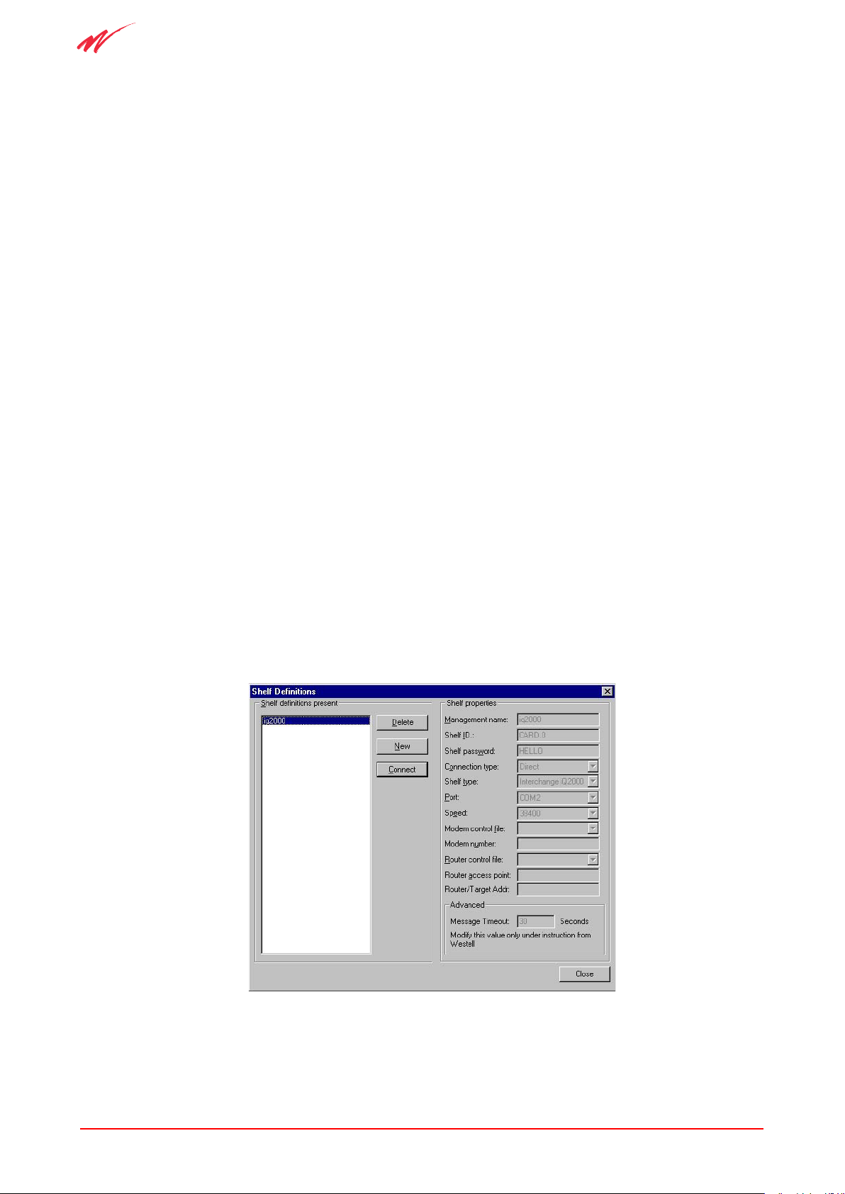
4.7.4 Shelf Definitions
Figure 11: Shelf Definitions Dialogue Box.
 Loading...