

Westell DSP95 PAW User Manual

PRODUCT M
A
N
UAL
DSP95 Series Digital Repeater Line
User’s Guide
W
©Westell Technologies. 960-1152-MNL
ESTELL.COM
rG

Digital Repeater Line
DSP95 Series User’s Guide
DISCLAIMER
All information and statements contained herein are accurate to the best of Westell Technologies’ knowledge. Westell
Technologies makes no warranty with respect there to, including without limitation any results that may be obtained
from the products described herein or the infringement by such products of any property rights of any persons. Use
or application of such information or statements is at the users’ sole risk, without any liability on the part of Westell
Technologies. Nothing herein shall be construed as license or recommendation for use, which infringes upon any
propriety rights of any person. Product material and specifications are subject to change without notice. Westell
Technologies standard terms of sale and the specific terms of any particular sale apply.
Page 2 of 74
WESTELL.COM
1.877.844.4274 © 2016 Westell Technologies
25 May 2016 Doc. No. 960-1250-MNL rG

Digital Repeater Line
DSP95 Series User’s Guide
TABLE OF CONTENTS
Preface ........................................................................................................................................................................... 9
Purpose............................................................................................................................................................................................................. 9
Application ...................................................................................................................................................................................................... 9
Document Organization ............................................................................................................................................................................ 9
Reference ....................................................................................................................................................................................................... 10
Document Conventions ........................................................................................................................................................................... 10
Product Registration Information ........................................................................................................................................................ 11
Safety Guidelines ........................................................................................................................................................................................ 11
Important Safety
Industry Certifications/Registration Numbers: ............................................................................................................................... 12
FCC ID: NVRDSP95-PAW ......................................................................................................................................................................... 12
ISEDC: 4307A-DSP95PAW ....................................................................................................................................................................... 13
Technical Support....................................................................................................................................................................................... 13
Acronyms and Abbreviations ................................................................................................................................................................. 14
Information .................................................................................................................................................................. 12
1 Product Overview .............................................................................................................................................. 15
1.1 Product Information ................................................................................................................................................................... 15
1.2 Functional Overview................................................................................................................................................................... 15
1.3 LED Indicator ................................................................................................................................................................................. 16
1.4 Local Communication Interface Ports ................................................................................................................................. 17
1.5 EIA232 Pin Specifications ......................................................................................................................................................... 17
1.6 USB Interface ................................................................................................................................................................................ 17
1.7 Ethernet ........................................................................................................................................................................................... 17
1.8 Monitoring and Alarms ............................................................................................................................................................. 17
1.9 Circuit Operational Description ............................................................................................................................................. 18
2 Optimizing the System during Installation ................................................................................................... 19
2.1 System Setup Considerations ................................................................................................................................................ 19
2.2 Suggested Spectrum Analyzer Setting ............................................................................................................................... 19
2.3 Important Installation Notes .................................................................................................................................................. 20
2.4 Installation Guidelines ............................................................................................................................................................... 20
2.4.1 Donor Antenna ............................................................................................................................................................................. 20
2.4.2 Antennas .......................................................................................................................................................................................... 21
2.5 Optional Accessories ................................................................................................................................................................. 21
2.5.1 Outside Donor Antenna ............................................................................................................................................................ 21
2.5.2 Inside Omnidirectional Antenna ............................................................................................................................................ 21
Page 3 of 74
WESTELL.COM
1.877.844.4274 © 2016 Westell Technologies
25 May 2016 Doc. No. 960-1250-MNL rG

Digital Repeater Line
DSP95 Series User’s Guide
2.5.3 Power Dividers .............................................................................................................................................................................. 21
2.5.4 Grounding Kit ................................................................................................................................................................................ 21
2.5.5 Directional Couplers ................................................................................................................................................................... 21
2.5.6 19” Rack Shelf ................................................................................................................................................................................ 22
2.5.7 UPS..................................................................................................................................................................................................... 22
2.5.8 Cross Band Couplers ................................................................................................................................................................... 22
3 Web-Based GUI .................................................................................................................................................. 23
3.1 Web-Based GUI Session ........................................................................................................................................................... 23
3.2 System Status ............................................................................................................................................................................... 26
3.3 Local Network ............................................................................................................................................................................... 27
3.4 RF Configuration ......................................................................................................................................................................... 28
3.5 Program a Filter ........................................................................................................................................................................... 29
3.6 Remote Network ......................................................................................................................................................................... 30
3.7 SNMP Configuration .................................................................................................................................................................. 31
3.8 Time Configuration .................................................................................................................................................................... 31
3.9 System Health............................................................................................................................................................................... 32
3.10 Install and Upload ....................................................................................................................................................................... 33
3.11 Reboot ............................................................................................................................................................................................. 34
3.12 Alarm Configuration .................................................................................................................................................................. 35
3.13 Email Configuration.................................................................................................................................................................... 36
3.14 Log Configuration ....................................................................................................................................................................... 37
3.15 Account Credentials ................................................................................................................................................................... 38
4 Console Interface ............................................................................................................................................... 39
4.1 Text Menu Interface (Local Access) ...................................................................................................................................... 39
4.2 Telnet Session (Remote Access) ............................................................................................................................................ 44
4.3 Modem Interface (Remote Access with Login) ............................................................................................................... 46
4.4 Additional Tips ............................................................................................................................................................................. 47
Appendix A Attenuation and Dynamic Range Guidelines ............................................................................ 51
A.1 Donor Port ..................................................................................................................................................................................... 51
A.2 Server Port ..................................................................................................................................................................................... 51
A.3 Dynamic Range Thresholds .................................................................................................................................................... 52
A.4 Large Deltas between In-band and Composite Input Signals .................................................................................. 52
Appendix B Band Plans and Filter File Naming Conventions .......................................................................... 53
B.1
Frequency Band
Plans ................................................................................................................................................................. 53
B.1.1 700 MHz Lower A, B and C Band Plan ................................................................................................................................. 53
Page 4 of 74
WESTELL.COM
1.877.844.4274 © 2016 Westell Technologies
25 May 2016 Doc. No. 960-1250-MNL rG

Digital Repeater Line
DSP95 Series User’s Guide
B.1.2 700 MHz Upper C Band Plan ................................................................................................................................................... 54
B.1.3
Cellular Frequency Band
Plan .................................................................................................................................................... 54
B.1.4 AWS Frequency Band Plan ....................................................................................................................................................... 55
B.1.5 Canadian PCS Frequency Band Plan ..................................................................................................................................... 56
B.1.6 US PCS Frequency Band Plan .................................................................................................................................................. 57
B.1.7 Public Safety Bands ..................................................................................................................................................................... 57
B.2 Filter File Naming Conventions ............................................................................................................................................. 58
B.2.1
B.2.2
B.2.3
B.2.4 US
700 MHz Filter Naming
Cellular Filter
Canadian PCS Filter
PCS Filter
File
Naming Convention
File
File
Naming
Convention ....................................................................................................................................... 58
.................................................................................................................................... 59
Naming
Convention ...................................................................................................................... 60
Convention ................................................................................................................................... 61
B.2.5 AWS Filter Naming Convention ............................................................................................................................................. 63
Appendix C Mechanical Configurations .............................................................................................................. 64
C.1 Digital Repeater Mechanical Drawings .............................................................................................................................. 64
C.2 Digital Repeater Mounting Drawings, Modular Series High Power ....................................................................... 64
C.2.1 Wall Mounting .............................................................................................................................................................................. 65
C.2.2 19” Relay Rack Mounting .......................................................................................................................................................... 66
C.2.3 19” Four Post Rack Mounting ................................................................................................................................................. 67
Appendix D Mechanical and Electrical Specifications ................................................................................... 68
D.1 Mechanical Specifications ........................................................................................................................................................ 68
D.2 AC Power Specifications ........................................................................................................................................................... 68
D.3 Environmental Requirements ................................................................................................................................................. 68
D.4 Operating Power Parameters ................................................................................................................................................. 69
Appendix E Port Configurations .......................................................................................................................... 71
E.1 Dual-band D2:D1 Port Configuration ................................................................................................................................. 71
E.2 Dual-band D1:D2 Port Configuration ................................................................................................................................. 71
E.3 Dual-band D2:D2 Port Configuration ................................................................................................................................. 72
E.4 Dual-band D1:D1 Port Configuration ................................................................................................................................. 72
Appendix F Acronyms and Abbreviations .......................................................................................................... 73
Page 5 of 74
WESTELL.COM
1.877.844.4274 © 2016 Westell Technologies
25 May 2016 Doc. No. 960-1250-MNL rG

Digital Repeater Line
DSP95 Series User’s Guide
TABLE OF FIGURES
Figure 1-1: Pin Description .................................................................................................................................................................................17
Figure 3-1: User Connection Login ..................................................................................................................................................................23
Figure 3-2: System Status ....................................................................................................................................................................................26
Figure 3-4: Local Network ...................................................................................................................................................................................27
Figure 3-5: RF Configuration ..............................................................................................................................................................................28
Figure 3-6: Program a Filter ...............................................................................................................................................................................29
Figure 3-7: Remote Network..............................................................................................................................................................................30
Figure 3-8: SNMP Configuration ......................................................................................................................................................................31
Figure 3-9: Time Configuration .........................................................................................................................................................................31
Figure 3-10: System Health ................................................................................................................................................................................32
Figure 3-11: Install & Upload.............................................................................................................................................................................33
Figure 3-12: Reboot ...............................................................................................................................................................................................34
Figure 3-13: Alarm Configuration ....................................................................................................................................................................35
Figure 3-14: Email Configuration .....................................................................................................................................................................36
Figure 3-15: Log Configuration .........................................................................................................................................................................37
Figure 3-16: Account Credentials .....................................................................................................................................................................38
Figure 4-1: Null Modem Cable ..........................................................................................................................................................................39
Figure 4-2: Gender Adapter ...............................................................................................................................................................................39
Figure 4-3: Tera Term Pro Web Start Up .......................................................................................................................................................39
Figure 4-4: Serial Radio Button .........................................................................................................................................................................40
Figure 4-5: Setup ....................................................................................................................................................................................................40
Figure 4-6: Serial Port Setup ..............................................................................................................................................................................41
Figure 4-7: TMI Main Menu ................................................................................................................................................................................42
Figure 4-8: Adjust Gain.........................................................................................................................................................................................43
Figure 4-9: User Gain ............................................................................................................................................................................................43
Figure 4-10: Selecting Filter Programs ...........................................................................................................................................................44
Figure 4-11: Default IP Address ........................................................................................................................................................................45
Figure 4-12: Login Screen ...................................................................................................................................................................................45
Figure 4-13: Main Menu ......................................................................................................................................................................................46
Figure 4-14: Control Panel ..................................................................................................................................................................................47
Page 6 of 74
WESTELL.COM
1.877.844.4274 © 2016 Westell Technologies
25 May 2016 Doc. No. 960-1250-MNL rG

Digital Repeater Line
DSP95 Series User’s Guide
Figure 4-15: View Network Status and Tasks ..............................................................................................................................................47
Figure 4-16: Change Adapter Settings...........................................................................................................................................................48
Figure 4-17: Local Area Network ......................................................................................................................................................................48
Figure 4-18: Internet Protocol Version 4 (TCP/IPv4) ................................................................................................................................49
Figure 4-19: Enter IP Address ............................................................................................................................................................................49
Figure B-1: : 700 MHz Lower A, B and C Band Plan ..................................................................................................................................53
Figure B-2: : 700 MHz Upper C Band Plan ....................................................................................................................................................54
Figure B-3:
Cellular Frequency Band
Plan .......................................................................................................................................................54
Figure B-4: AWS Frequency Band Plan ..........................................................................................................................................................55
Figure B-5: Canadian PCS Frequency Band Plan ........................................................................................................................................56
Figure B-6: US PCS Frequency Band Plan .....................................................................................................................................................57
Figure B-7: Public Safety Bands ........................................................................................................................................................................57
Figure C-1: Digital Repeater Drawing .............................................................................................................................................................64
Figure C-1: Install Wall Mounting Brackets ..................................................................................................................................................65
Figure C-3: Rack Mounting .................................................................................................................................................................................66
Figure C-4: 19” Four Post Rack Mounting ....................................................................................................................................................67
Figure E-1: Dual-band D2:D1 Port Configuration ......................................................................................................................................71
Figure E-2: Dual-band D1:D2 Port Configuration ......................................................................................................................................71
Figure E-3: Dual-band D2:D2 Port Configuration ......................................................................................................................................72
Figure E-4: Dual-band D1:D1 Port Configuration ......................................................................................................................................72
TABLE OF TABLES
Table P-1: Document Conventions ..................................................................................................................................................................10
Table F-1: Acronyms and Abbreviations .......................................................................................................................................................73
Table A-1: Dynamic Range Thresholds ..........................................................................................................................................................52
Table B-1:
Table B-2:
Table B-3:
Table B-4: US
Table D-1: Mechanical Specifications .............................................................................................................................................................68
Table D-2: AC Power Specifications ................................................................................................................................................................68
1.877.844.4274 © 2016 Westell Technologies
25 May 2016 Doc. No. 960-1250-MNL rG
700 MHz Filter Naming
Cellular Filter
File
Canadian PCS Filter
PCS Filter
File
Convention ............................................................................................................................................58
Naming Convention
File
Naming
Naming
Convention ........................................................................................................................................61
.........................................................................................................................................59
Convention ...........................................................................................................................60
WESTELL.COM
Page 7 of 74

Digital Repeater Line
DSP95 Series User’s Guide
Table D-3: Environmental Requirements ......................................................................................................................................................68
Table D-1: Operating Power Parameters ......................................................................................................................................................69
Page 8 of 74
WESTELL.COM
1.877.844.4274 © 2016 Westell Technologies
25 May 2016 Doc. No. 960-1250-MNL rG

Digital Repeater Line
DSP95 Series User’s Guide
Preface
This Preface includes the following:
• Purpose
• Application
• Document Organization
• References
• Document Conventions
• Product Registration Information
• Safety Notices
• Important Safety Information
• Radio and Television Interferences
• Industry Certifications/Registration Numbers
• Technical Support
• Acronyms and Abbreviations
Purpose
The purpose of this document is to provide a procedure to help experienced technicians/engineers install and
commission an in-building wireless enhancement repeater system using Westell Technologies digital repeaters. This
document was written to address the practical concerns of the installer. Following the procedures in this manual will
minimize risks associated with modifying a live system and will prevent service interruptions. This document assumes
the technician/engineer understands the basic principles and functionality involved with repeater and in-building
systems.
Application
Apply this
guide when
adding
digital repeater capability
to an
existing system
or
as part of a
new installation.
Document Organization
This manual includes the following chapters:
Chapter 1: Product Overview – Provides an Overview of DSP95 Series Repeaters
Chapter 2: System Optimization Installation Tips – Provides information for system optimization
Chapter 3: Web-Based GUI – Provides information about using the system through a web-based graphical user
interface
Chapter 4: Console Interface – Provides information about local access to the repeater through console interface
Appendix A: Attenuation and Dynamic Range Guidelines – Provides information about attenuation and dynamic
range guidelines
Page 9 of 74
WESTELL.COM
1.877.844.4274 © 2016 Westell Technologies
25 May 2016 Doc. No. 960-1250-MNL rG
Digital Repeater Line
Command1 >
DSP95 Series User’s Guide
Appendix B: Band Plans and Filter File Naming Conventions – Provides information about the band plans and
filter file naming conventions
Appendix C: Mechanical Configurations – Provides mechanical drawings and mounting diagrams for the system
Appendix D: Mechanical and Electrical Specifications – Provides the mechanical and electrical speciation for the
system
Appendix E: Port Configuration – Details and illustrates the port configurations for each repeater type
Appendix F: Glossary – Provides a table of acronyms and abbreviations used in this manual and a definition for each
Reference
• Westell Technologies Power Supply Users Guide, part number 960-1152-MNL
Document Conventions
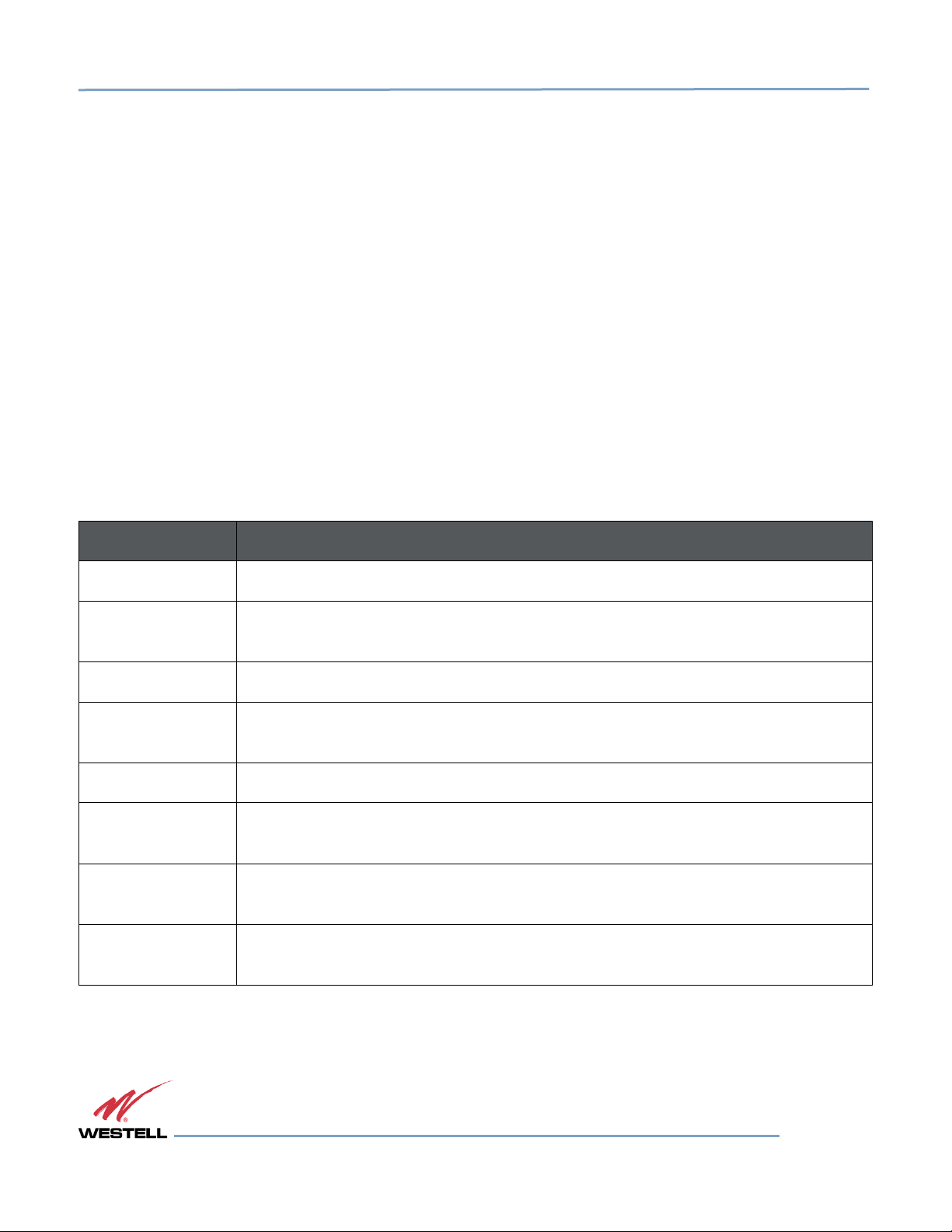
Table P-1 lists the conventions used throughout this document.
Table P-1: Document Conventions
Convention Description
DANGER! Description of an imminent hazard that, if not avoided, may result in severe injury or death.
WARNING! Description of an imminent hazard that, if not avoided, may result in injury or serious
equipment damage.
CAUTION Description of an imminent hazard that, if not avoided, could result in equipment damage.
IMPORTANT Additional information that is very important for the user to know. More critical than a note,
but does not contain a Danger!, Warning! or Caution.
NOTE Additional information or comments that may be beneficial for the user to know.
Bold Bold typeface indicates commands, buttons, keyboard keys, user interface elements, and
provides emphasis.
The > symbol between commands indicates a succession of commands. For example, select
Command2
Start > Settings.
Key1+Key2 A plus sign between key names indicates simultaneous keyboard commands. Press and
hold down the first key while pressing the second key. For example, Ctrl+X.
1.877.844.4274 © 2016 Westell Technologies
25 May 2016 Doc. No. 960-1250-MNL rG
Page 10 of 74
WESTELL.COM
Digital Repeater Line
DSP95 Series User’s Guide
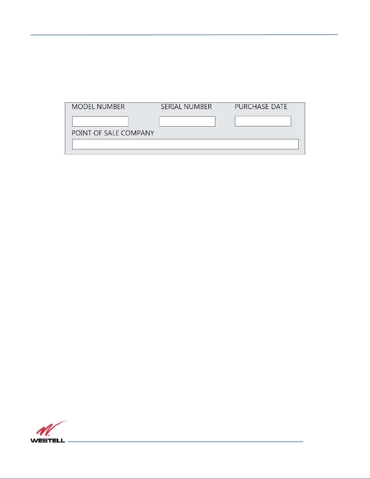
Product Registration Information
The product serial number is located on the label on the bottom panel, near the power connectors. Record the serial
number, model number, purchase date and point-of-sale company in the boxes in Figure P-1 below. Retain this
manual, along with proof of purchase, to serve as a permanent record of your purchase.
Figure P-1: Product Registration Information
Safety Guidelines
The general safety information in this section applies to both operating and service personnel. Specific warnings and
cautions are located in other parts of this manual to which they apply, but may not appear in this summary. Failure
to comply with these precautions or specific warnings elsewhere in the manual violates safety standards of design,
manufacture, and intended use of equipment. Westell Technologies assumes no liability for the customer’s failure to
comply with these requirements:
Grounding: This digital repeater system is designed to operate from 100 - 240 VAC and must always be operated
with the ground wire properly connected. Do not remove or otherwise alter the grounding lug on the power cord.
Explosive atmospheres: To avoid explosion or fire, do not operate this product in the presence of flammable gases
or fumes.
Lightning danger: Do not install or adjust this unit during an electrical storm. We strongly recommend the use of a
suitable lightning arrester.
There are no user-serviceable parts inside the repeater.
DANGER!
Hazardous voltages are present when the cover is removed. Do not open the
repeater enclosure. If you suspect a malfunction with this product, call your dealer
or call Westell Technologies technical support line at 1.877.844.4274.
WARNING!
Disconnect/remove power before connecting or disconnecting cables.
Page 11 of 74
WESTELL.COM
1.877.844.4274 © 2016 Westell Technologies
25 May 2016 Doc. No. 960-1250-MNL rG
Digital Repeater Line
DSP95 Series User’s Guide
Important Safety
Information
Antennas used to radiate signals indoors are limited to a maximum gain of 3 dBi. The output power setting and
antenna used for the up-link (1710-1755MHz) must be configured to ensure that the eirp does not exceed 1Watt and
is limited to a maximum antenna height of 10 meters above ground. Position each antenna to observe minimum
separation requirements from all users and bystanders.
Use the following guidelines when considering separation distances.
• Place indoor antennas such that, under normal conditions, personnel cannot come within 50 cm (~20
in) from any inside antenna. Adhering to this minimum separation ensures that bystanders cannot
exceed RF exposures beyond the maximum permissible limit for uncontrolled exposure.
• Position outdoor antennas such that, under normal conditions, personnel cannot approach closer
than 183 cm (~6 ft.).
Canadian Compliance Information: This device complies with ISEDC license-exempt RSS standard(s). Operation is
subject to the following two conditions: (1) this device may not cause interference, and (2) this device must accept
any interference, including interference that may cause undesired operation of the device. Le présent appareil est
conforme aux CNR ISEDC applicables aux appareils radio exempts de licence. L'exploitation est autorisée aux deux
conditions suivantes : (1) l'appareil ne doit pas produire de brouillage, et (2) l'utilisateur de l'appareil doit accepter
tout brouillage radioélectrique subi, même si le brouillage est susceptible d'en compromettre le fonctionnement.
Industry Certifications/Registration Numbers:
FCC ID: NVRDSP95-PAW
IC: 4307A-DSP95PAW
Power Supply: UL60950-1
The FCC requires the user to be notified that any changes or modifications made to this device that are not expressly
approved by Westell may void the user's authority to operate the equipment. This device must not be co-located or
operated in conjunction with any other antenna or transmitter. Specific models referenced throughout this manual
are limited to operation at the frequencies for which they were certified. Model DSP95-PAW is certified for 1850-1910
MHz / 1930-1990 MHz and 1710-1755 MHz/ 2110-2155 MHz operation only.
Page 12 of 74
WESTELL.COM
1.877.844.4274 © 2016 Westell Technologies
25 May 2016 Doc. No. 960-1250-MNL rG

Digital Repeater Line
DSP95 Series User’s Guide
Renseignements importants en matière
Antennes utilisées pour émettre des signaux à l’intérieur sont limitées à un maximum de gain de 3 dBi. Le réglage de
puissance de sortie et l’antenne utilisée pour la liaison montante (1710-1755MHz) doivent être configurés pour
s’assurer que la pire ne dépasse pas 1 Watt et est limitée à une hauteur maximale de l’antenne de 10 mètres audessus du sol. Positionner chaque antenne afin d’observer les exigences de séparation minimale de tous les
utilisateurs et les passants.
Utilisez les instructions suivantes lors de l’examen des distances de séparation.
• Placer les antennes intérieures telles que, dans des conditions normales, le personnel ne peut pas
moins de 50 cm (20 po) de l’un à l’intérieur de l’antenne. Adhérant à cette séparation minimale s’assure
que les passants ne peuvent excéder exposition RF au-delà de la limite maximale admissible pour
une exposition non contrôlée
• Position antennes extérieures telle que, dans des conditions normales, le personnel ne peut pas
approcher moins 183 cm (6 pieds).
Le présent appareil est conforme aux CNR ISEDC applicables aux appareils radio exempts de licence. L'exploitation
est autorisée aux deux conditions suivantes : (1) l'appareil ne doit pas produire de brouillage, et (2) l'utilisateur de
l'appareil doit accepter tout brouillage radioélectrique subi, même si le brouillage est susceptible d'en
compromettre le fonctionnement.
Certifications de l’industrie immatriculations: FCC ID: NVRDSP95-PAW
ISEDC: 4307A-DSP95PAW
Bloc d’alimentation: UL60950-1
La FCC exige que l’utilisateur d’être averti que toute modification apportée à cet appareil qui n’est pas expressément
approuvées par Westell peut annuler autorisation votre d’utiliser l’équipement. Ce dispositif ne doit pas être coimplanté ou exploité conjointement avec toute autre antenne ou transmetteur. Modèles spécifiques mentionnés
dans ce manuel sont limités au fonctionnement aux fréquences pour lesquelles ils ont été certifiés. Modèle DSP95PAW est certifié pour l’opération 1850-1910 MHz/1930-1990 MHz et de 2110-2155 MHz / 1710-1755 MHz seulement.
Technical Support
If you suspect a malfunction with this product or have a technical question, call your dealer or the Westell
Technologies In-Building Wireless Support Line at: (603) 626-6677, Toll Free (USA) 1-877-844-4274, press option 2
then option 1. They can also be reached at
ibwsupport@westell.com
.
Page 13 of 74
WESTELL.COM
1.877.844.4274 © 2016 Westell Technologies
25 May 2016 Doc. No. 960-1250-MNL rG

Digital Repeater Line
DSP95 Series User’s Guide
Acronyms and Abbreviations
Refer to Appendix F at the end of this manual for definitions of the acronyms and abbreviations used in this manual.
Page 14 of 74
WESTELL.COM
1.877.844.4274 © 2016 Westell Technologies
25 May 2016 Doc. No. 960-1250-MNL rG

Digital Repeater Line
DSP95 Series User’s Guide
1 Product Overview
1.1 Product Information
Westell Technologies digital repeaters were developed for use within enclosed structures where sufficient signal
strength from local cell sites to operate cell phones is unavailable. Adequate signal strength must be available outside
the structure as a prerequisite to achieving in-building coverage. The digital repeater is connected to an external
antenna, usually on the roof, and to one or more internal antennas placed strategically throughout the area where
wireless service is desired.
The external antenna is typically a directional type, such as a Yagi antenna. Internal antennas are typically
omnidirectional, though
repeater amplifies both the uplink
communications to and from the intended wireless infrastructure.
With a maximum total of 90 dB nominal gain on both the uplink and downlink, gain can be adjusted over a range
from 58.5 dB to 90 dB in 0.5 dB steps. Control of the repeater is achieved utilizing a computer connected to a COM
port or via a crossover Ethernet cable connected to the Ethernet port.
A specific filtering process modifies each amplification chain. This process digitally converts the assigned spectrum
and then applies digital signal processing (DSP) techniques. DSP is used to create passbands that selects the RF
energy passing through either the uplink or downlink paths. After the digital processing is complete, the information
is converted back to an analog signal that is applied to the remaining stages of amplification. The resulting signals
emitted by the repeater are specific to the network service providers’ requirements. If these requirements change,
only the DSP configuration parameters must change. Configuration parameters are created at the factory and
supplied as files to be downloaded to the repeater. The filter set configurations stored in memory determine the
unit’s adaptability to various field applications. Appendix B describes the band plans and the convention Westell uses
to identify and store the files that make up the filter set. All Westell repeaters are shipped with an active filter set that
is programmed according to customer specifications. In most cases, the installer will not be required to program a
filter.
various other types may be used, depending on the coverage application. The Westell DSP
(phone to tower) and downlink (tower to phone) signals, facilitating
1.2 Functional Overview
Westell Technologies digital repeaters incorporate the following features for convenient operation, access, protection,
and control:
• Network configuration and control using either a web GUI accessed using a web browser or a menu
driven user interface using the serial port. The GUI does not require Internet access.
• User gain control (affects all passbands)
• Automatic gain control
• Automatic power control
• Overdrive protection (PA limiting)
• Under/Over voltage protection
• Fault protection
• Alarm notification - local/remote
Page 15 of 74
WESTELL.COM
1.877.844.4274 © 2016 Westell Technologies
25 May 2016 Doc. No. 960-1250-MNL rG

Digital Repeater Line
DSP95 Series User’s Guide
• Upgrade support - local/remote
• External interfaces - USB/ethernet/Serial
• Re-loadable filters - local/remote
• Web-based monitoring and control - local/remote
• Persistent status and error information
1.3 LED Indicator
Westell Technologies automatic safety precautions are built into the amplifier system. In the case of a catastrophic
system event, a shutdown circuit will disable all emissions if the uplink input or downlink input is overdriven or if an
oscillation or output overpower event occurs. The amplifier will periodically attempt to recover from the detected
condition.
Status LED states are:
• Blinking yellow: Unit is migrating the database after an upgrade
• Blinking red: Unit is programming the filter(s) and there is an error condition
• Blinking green: Boot up or unit is programming the filter(s) and no error condition exists
• Solid green: Unit is operational, PA is on
• Solid yellow: Unit is operational, but AGC is on
• Solid red: Unit has an error condition or PA is off
• Dark: Unit is not powered
Check the GUI status page for the nature of the fault.
On
power
up, the
computer
to
blink green on and off at a rate of
in the
boot
repeater
boot. During
will
require approximately three (3) minutes
this time the LED
approximately
up process. Filter configuration file loading will show green light blink
two (2) seconds on / three (3) seconds off until finished.
NOTE
labeled Power/Fault
or
for the
Status
internal
will
1 Hz. This will indicate that the unit is
slowly
Do not
unplug
the unit
while
it is in the
boot
up process.
Page 16 of 74
WESTELL.COM
1.877.844.4274 © 2016 Westell Technologies
25 May 2016 Doc. No. 960-1250-MNL rG
Digital Repeater Line
DSP95 Series User’s Guide
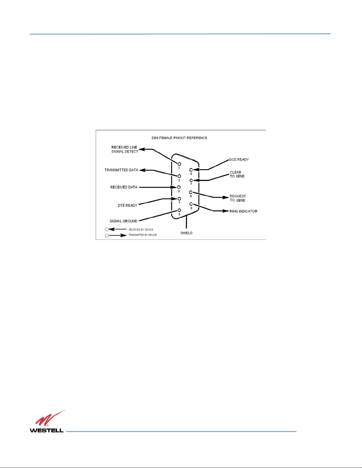
1.4 Local Communication Interface Ports
To allow monitoring and control, Westell Technologies repeaters are equipped with four ports that provide external
communication access (one Ethernet CAT-5, one DB-9 serial, and two USB). The Ethernet, CAT-5 port is provided as
a primary communications port to the PC. The serial interface provides communications to a PC. The USB interface
provides a means to download files from a memory device. The DB-9 pin assignments conform to the standard
Electronic Industries Association (EIA232) specification. A diagram of the pin descriptions is provided in
for reference. Connecting a null modem cable to one of the COM ports and using a terminal emulation program with
a PC will allow communication to the control processor’s Text Menu Interface (TMI).
Figure 1-1
Figure 1-1: Pin Description
1.5 EIA232 Pin Specifications
The connection diagram in Figure 1-1 is for reference only. It is intended as a resource for pinout information if it is
necessary to adapt your serial cable because of an unusual connector configuration. In the majority of cases, this
information is not needed.
1.6 USB Interface
This port is used for software updates and filter file uploads.
1.7 Ethernet
This port is
used
to
provide local or remote access
to the GUI.
1.8 Monitoring and Alarms
The DSP95 series can be monitored via an ethernet connection using SNMP, SSH and/or HTTP protocols. Public
Safety DSP models have dry contacts for traditional alarm panel monitoring as well.
Page 17 of 74
WESTELL.COM
1.877.844.4274 © 2016 Westell Technologies
25 May 2016 Doc. No. 960-1250-MNL rG

Digital Repeater Line
DSP95 Series User’s Guide
1.9 Circuit Operational Description
The repeater uses a single down conversion/up conversion scheme. There are multiple RF amplifier stages prior to
each down-converting mixer. The down-converting mixers are followed by a single IF amplifier. A DSP block then
processes the resultant digitized IF signal that was previously generated by an analog-to-digital converter. The
filtered digital signal is fed to a digital-to-analog converter and then up-converted to RF. A driver amplifier and a
power amplifier make up the final gain stages before application to the diplexer. The maximum total system gain
(diplexer input to diplexer output) is nominally 90 dB for either the downlink or the uplink paths with both links having
independent manual and Automatic Gain Controls (AGC).
AGC reacts to analog power detection on both the input and output of the uplink and downlink RF chains. A control
algorithm continuously monitors these detected values and dynamically adjusts various gain stages. The net system
gain value, entered manually, is optimally maintained without exceeding FCC parameters or overdriving the A/D
converters.
The Status or Power/Fault LED provides immediate visual indication of the unit’s primary power alarm status. The
repeater features automatic shutdown protection as a safety measure if excessive drive is applied to the input or an
oscillation condition occur. When in a protected mode, a control algorithm determines the appropriate method of
recovery to a normal, previously defined state, or maintains the protection until it is manually reset. If recovery has
been established, the LED is illuminated green or available to be reset. The events that trigger the error will be saved
in the event log.
Page 18 of 74
WESTELL.COM
1.877.844.4274 © 2016 Westell Technologies
25 May 2016 Doc. No. 960-1250-MNL rG

Digital Repeater Line
DSP95 Series User’s Guide
2 Optimizing the System during Installation
2.1 System Setup Considerations
Check all cables for shorts and opens. Verify that there are no cables with loose or poor connections. RF leakage
could cause oscillation to occur under some conditions.
Check the rooftop antenna (donor antenna), if directional, for proper alignment along the calculated compass
heading. Typically, the directional antenna is aimed at the same site that your handset uses, but it may not always
be. It is critical that the installer contact the service provider for information about, and approval of, the selected cell
site before the system is activated.
IMPORTANT
The installation height of the antenna for AWS band (1700/2100 MHz) operations is
limited to 10 meters above ground for compliance with Section 27.50.
If cables and alignment are acceptable and a problem persists, it may be necessary to use a spectrum analyzer to
examine the signal environment in which the repeater is operating. The existence of strong adjacent channel signals
within the frequency band(s) can cause the AGC to reduce the amplifier’s gain or cause alarms. In some cases,
additional filtering or attenuation might be required to reject these unwanted signals. In some instances, the donor
antenna can be reoriented horizontally, to place the interference source in an antenna pattern null. There also may
be some cases where the interference from outside signals is so great that they cannot be filtered or otherwise
reduced or eliminated without expensive and possibly prohibitive measures. In these cases, it may not be practical
to use the repeater for providing coverage to these sites.
2.2 Suggested Spectrum Analyzer Setting
When troubleshooting RF issues and surveying challenging RF environments, it is important to have a spectrum
analyzer that is capable of measuring the frequency you are using. Use an attenuator to protect the input when
connected to a source of RF power, such as a repeater or a powered DAS.
Measure both uplink and downlink.
Measure downlink on the donor cable and at the output (server) port of the powered repeater.
Measure uplink at the lead from the DAS (on fiber-powered DAS, where the lead would connect to the server port on
the repeater) and at the donor port with the repeater power on.
Measurements may also be necessary at server antenna locations. The spectrum analyzer must be equipped with a
whip antenna.
Set the resolution bandwidth (RBW) to 200 kHz for GSM and 1 MHz for CDMA. If you cannot select these values, use
the closest available values. Set the video filter to about one-tenth of RBW. Set other settings, such as span, to the
appropriate values. Ensure that there are no signals above the top of the screen.
If you cannot see an adjacent out-of-band signal when using the 1 MHz RBW filter, decrease the RBW to see the
close-in-frequency signals. Set the RBW back when you want to measure the power level.
Page 19 of 74
WESTELL.COM
1.877.844.4274 © 2016 Westell Technologies
25 May 2016 Doc. No. 960-1250-MNL rG

Digital Repeater Line
DSP95 Series User’s Guide
2.3 Important Installation Notes
Inadequate isolation between the outside and inside antennas may cause regenerative feedback in the system. This
feedback can cause the amplifier to emit a continuous signal at maximum amplitude and, in some cases, interfere
with normal operation of the cell site. It is important to carefully consider the layout and placement of the system.
Refer to the Preface Safety Guidelines and Important Safety Information for proper antenna selection and
installation.
DANGER!
To avoid serious injury or death and repeater damage, do not install donor or server
antennas near overhead power lines or high power components. Allow enough
distance so that, if antennas fall, they will not contact those components.
WARNING!
Close proximity to the donor or server antennas with the repeater in operation may
expose the user or installer to RF fields that exceed FCC limits for human exposure.
CAUTION
Amplifier or handset damage may occur if a handset is connected directly to the
repeater or to the coax that leads to the repeater.
2.4 Installation Guidelines
2.4.1 Donor Antenna
• Accurately determine the azimuth to the donor cell site.
• Obtain the donor site information and approval from the service provider/carrier.
• Ensure that the radiation path to the donor cell site is as unobstructed as possible.
• Mount the donor antenna at or toward the edge of the roof, in the direction of the donor site. Try
to avoid having the RF signal from the donor pass above the location(s) of the service antennas.
Normally, service antennas are located behind and below the donor antenna (as viewed from above).
This approach will help avoid interference and feedback to and from the service antennas.
• Normally, mounting the donor antenna higher will allow a less obstructed path to the donor site.
However, in high traffic metro areas avoid mounting the donor antenna any higher than necessary
as the quality of the donor signal may start to become less stable and it is more likely to encounter
adjacent channel interference.
• When possible, shield the donor antenna’s backside by locating it so that any HVAC units and/or
penthouse structures are behind the antenna relative to the donor cell site location.
• Ground system components in accordance with NEC 810-15, 21 as required.
Page 20 of 74
WESTELL.COM
1.877.844.4274 © 2016 Westell Technologies
25 May 2016 Doc. No. 960-1250-MNL rG

Digital Repeater Line
DSP95 Series User’s Guide
2.4.2 Antennas
• Use omnidirectional antennas indoors, and locate them centrally with respect to the intended
coverage area to minimize signal leakage to the outside. Use directional antennas indoors only in
special cases when higher gain and directionality would be helpful and RF exposure limits will not be
exceeded.
• To avoid repeater uplink overload and gain limiting, mount the indoor antennas away from areas
where mobile subscribers frequently use their phones such as desks or dispatch areas.
• To determine the quantity and locations of indoor antennas, use an appropriate phone’s signal meter
to determine areas of weak signals. These are the approximate areas where indoor antennas may be
needed. Be aware the signal from an indoor antenna, in most cases, can be expected to penetrate
about two standard office sheetrock-type walls to reach users. After two walls, or if the walls are
made of other materials, it may be necessary to split the available signal and add more antennas.
2.5 Optional Accessories
A
complete line
any additional items needed.
of
accessories
is
available from Westell Technologies. Check with your Westell Technologies distributor for
Below are just a few
examples suitable
for
most in-building
needs.
2.5.1 Outside Donor Antenna
• PCS - model number CSI-AY/1.85-1.99/10
• Cellular - model number CSI-AY/806-960/14
2.5.2 Inside Omnidirectional Antenna
• Quad-band - model number ClearLink-O/698-2.7K/N
2.5.3 Power Dividers
• 2:1 - model number ClearLink -SPD2/698-2.7K-LP/N
• 3:1 - model number ClearLink -SPD3/698-2.7K-LP/N
• 4:1 - model number ClearLink -SPD4/698-2.7K-LP/N
2.5.4 Grounding Kit
• Model number CSI-GKIT
2.5.5 Directional Couplers
• 6 dB - model number ClearLink-DC6/698-2.7K/N
• 10 dB - model number ClearLink -DC10/698-2.7K/N
• 15 dB - model number ClearLink -DC15/698-2.7K/N
• 20 dB - model number ClearLink -DC20/698-2.7K/N
• 30 dB - model number ClearLink -DC30/698-2.7K/N
Page 21 of 74
WESTELL.COM
1.877.844.4274 © 2016 Westell Technologies
25 May 2016 Doc. No. 960-1250-MNL rG

Digital Repeater Line
DSP95 Series User’s Guide
2.5.6 19” Rack Shelf
• Model number CSI-RMS-250
2.5.7 UPS
• Battery backup, two hour single-band, one hour dual-band - model number CS48-985-600
• Battery backup, four hour single-band, two hour dual-band - model number CS48-985-601
2.5.8 Cross Band Couplers
• Quad-band Rack Mount - model number CSI-CM250-7/C/AW/P (700 LTE, Cellular, PCS and AWS)
• Quad-band Wall Mount - model number CSI-CBC/QUAD/N (700 LTE, Cellular, PCS and ASW)
• Tri-band Rack Mount - model number CSI-CM250-U7C/C/P (700 Upper C LTE, Cellular and PCS)
• Tri-band Wall Mount - model number CSI-CBC21/740-1990/N (700 Upper C LTE, Cellular and PCS)
• Tri-band Rack Mount - model number CSI-CM250-L7/C/P (700 Lower A/B/C LTE, Cellular and PCS)
• Tri-band Wall Mount - model number CSI-CBC21/696-1990/N (700 Lower A/B/C LTE, Cellular and
PCS)
Page 22 of 74
WESTELL.COM
1.877.844.4274 © 2016 Westell Technologies
25 May 2016 Doc. No. 960-1250-MNL rG
Digital Repeater Line
DSP95 Series User’s Guide
3 Web-Based GUI
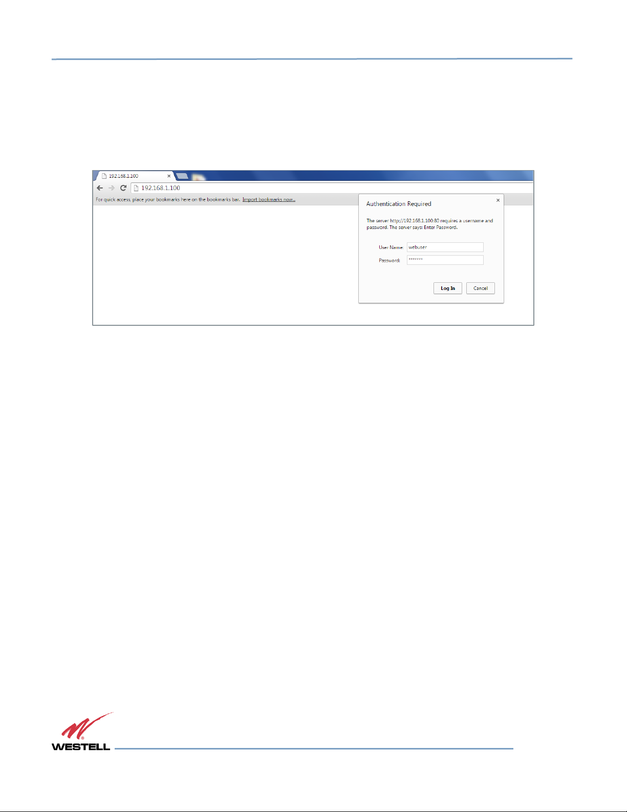
3.1 Web-Based GUI Session
You may access the repeater using a LAN connection and a web browser program such as Internet Explorer, Figure
3-1.
Figure 3-1: User Connection Login
The repeater ships with the default IP address of 192.168.1.100, but can be changed later if required.
1. If connecting directly to the repeater from a laptop or PC with a crossover CAT-5e cable or over a
LAN, enter the IP address of the repeater into the browser address line to connect.
Most users will need to update the TCP/IP settings on their computer to enable connection to a host that has a static
IP. Refer to section 0 If the repeater is properly equipped, you may use a modem to gain remote access to the
repeater. A selection of modems are available as options.
After you have installed and activated the modem, you can access it from any web browser. Access response time
depends on many factors, some of which are:
• Quality of the connection (RF signal in the case of wireless modems)
• Technology (CDMA, LTE, GPRS, etc.)
• Network congestion (throughput)
When a connection has been established, the login screen shown in both the GUI Serial and Telnet examples displays.
Page 23 of 74
WESTELL.COM
1.877.844.4274 © 2016 Westell Technologies
25 May 2016 Doc. No. 960-1250-MNL rG
 Loading...