

Westell DSP85 Original Product Manual

Digital Repeater Line
DSP85 Original Series plus
Modular 250 and 251 Series
PRODUCT M
A
N
UAL
W
©Westell Technologies. 960-1666-MNL
ESTELL.COM
rF

Digital Repeater Line
DSP85 Original Series plus Modular 250 and 251 Series
DISCLAIMER
All information and statements contained herein are accurate to the best of Westell Technologies knowledge. Westell
Technologies makes no warranty with respect there to, including without limitation any results that may be obtained
from the products described herein or the infringement by such products of any property rights of any persons. Use
or application of such information or statements is at the users’ sole risk, without any liability on the part of Westell
Technologies. Nothing herein shall be construed as license or recommendation for use, which infringes upon any
propriety rights of any person. Product material and specifications are subject to change without notice. Westell
Technologies standard terms of sale and the specific terms of any particular sale apply.
© 2015 Westell Technologies 9 September 2015 Doc. No. 960-1666-MNL rF
1.877.844.4274 Page 2 of 73
WESTELL.COM

Digital Repeater Line
DSP85 Original Series plus Modular 250 and 251 Series
TABLE OF CONTENTS
Preface
Purpose
Application ......................................................................................................................................................................................................8
Document Organization ............................................................................................................................................................................8
Document Conventions .............................................................................................................................................................................9
Product Registration Information ....................................................................................................................................................... 10
Safety Guidelines ....................................................................................................................................................................................... 10
Important Safety
Radio
Industry Certifications/Registration Numbers .............................................................................................................................. 11
Technical Support ...................................................................................................................................................................................... 11
Acronyms and Abbreviations ................................................................................................................................................................ 11
1
1.1
1.2
1.3
1.4
1.5
1.6
1.7
1.8
1.9
1.10Functional Block Diagrams ..................................................................................................................................................... 15
.............................................................................................................................................................................................................8
Information ................................................................................................................................................................. 10
and Television Interference ........................................................................................................................................................ 11
Product Overview
Product Information ................................................................................................................................................................. 12
Functional
LED Indicator ................................................................................................................................................................................ 13
Local Communication Interface Ports................................................................................................................................ 13
EIA232
USB Interface ................................................................................................................................................................................ 14
Ethernet .......................................................................................................................................................................................... 14
Monitoring and Alarms ............................................................................................................................................................ 14
Circuit Operational Description ............................................................................................................................................ 15
Overview ................................................................................................................................................................... 12
Pin Specifications ......................................................................................................................................................... 14
............................................................................................................................ 12
2
2.1
2.2
2.3
2.4
2.4.1Donor
2.4.2Antennas ................................................................................................................................................................................... 18
2.5
2.5.1Outside Donor
2.5.2Inside Omnidirectional
© 2015 Westell Technologies 9 September 2015 Doc. No. 960-1666-MNL rF
1.877.844.4274 Page 3 of 73
System Optimization Installation
System Setup
Suggested Spectrum Analyzer
Important Installation Notes ................................................................................................................................................. 17
Installation Tips ........................................................................................................................................................................... 18
Optional Accessories ................................................................................................................................................................ 19
Considerations ................................................................................................................................................. 17
Antenna ....................................................................................................................................................................... 18
Antenna ....................................................................................................................................................... 19
Antenna ........................................................................................................................................ 19
Tips ........................................................................................... 17
Setting ................................................................................................................................. 17
WESTELL.COM

Digital Repeater Line
DSP85 Original Series plus Modular 250 and 251 Series
2.5.3Power
2.5.4Grounding
2.5.5Lighting Arrestor
2.5.6Directional
2.5.719” Rack Shelf ......................................................................................................................................................................... 19
2.5.8UPS ............................................................................................................................................................................................. 19
2.5.9Cross Band Couplers ............................................................................................................................................................ 20
3
3.1
Web-based GUI Session .......................................................................................................................................................... 21
3.2
System
3.3
Local Network .............................................................................................................................................................................. 24
3.4
RF Configuration ......................................................................................................................................................................... 25
3.5
Program a Filter .......................................................................................................................................................................... 26
3.6
Remote Network ........................................................................................................................................................................ 27
3.7
SNMP
3.8
Time
3.9
System Health .............................................................................................................................................................................. 29
3.10Install and Upload ...................................................................................................................................................................... 30
3.11Reboot ............................................................................................................................................................................................ 31
3.12Alarm Configuration ................................................................................................................................................................. 32
3.13Email Configuration................................................................................................................................................................... 33
3.14Log Configuration ...................................................................................................................................................................... 34
3.15Account Credentials .................................................................................................................................................................. 35
Dividers ........................................................................................................................................................................ 19
Kit .......................................................................................................................................................................... 19
..................................................................................................................................................................... 19
Couplers .............................................................................................................................................................. 19
Web-based GUI .............................................................................................................................. 21
Status ............................................................................................................................................................................... 22
Configuration ................................................................................................................................................................. 28
Configuration .................................................................................................................................................................... 28
4
4.1
4.2
4.3
4.4
Appendix AAttenuation
A.1Donor
A.2Server
A.3Dynamic Range Thresholds ................................................................................................................................................... 47
A.4Large Deltas Between In-band and Composite Input Signals ................................................................................. 47
Appendix BBand Plans
B.1Frequency Band
© 2015 Westell Technologies 9 September 2015 Doc. No. 960-1666-MNL rF
1.877.844.4274 Page 4 of 73
Console Interface
Text Menu Interface (Local Access) .................................................................................................................................... 36
Telnet Session (Remote Access) ........................................................................................................................................... 40
Modem Interface (Remote Access with Login) .............................................................................................................. 41
Additional Tips ............................................................................................................................................................................ 42
Port ..................................................................................................................................................................................... 46
Port ..................................................................................................................................................................................... 46
............................................................................................................................. 36
and
Dynamic Range
and
Filter
File
Naming
Plans ................................................................................................................................................................ 48
Guidelines ................................................................................. 46
Conventions ............................................................................ 48
WESTELL.COM

Digital Repeater Line
DSP85 Original Series plus Modular 250 and 251 Series
700 MHz Lower A, B and C Band Plan .......................................................................................................................... 48
700 MHz Upper C Band Plan ............................................................................................................................................ 49
B.1.3Cellular Frequency Band
B.1.4AWS Frequency Band Plan ................................................................................................................................................ 50
B.1.5Canadian PCS Frequency Band Plan .............................................................................................................................. 50
B.1.6US PCS Frequency Band Plan ........................................................................................................................................... 51
B.1.7Public Safety Bands .............................................................................................................................................................. 51
B.2Filter
B.2.1700 MHz Filter Naming
B.2.2Cellular Filter
B.2.3Canadian PCS Filter
B.2.4US
File
Naming
PCS Filter
AWS Filter Naming
Conventions .............................................................................................................................................. 52
File
File
Naming
Plan ............................................................................................................................................. 49
Convention ................................................................................................................................ 52
Naming Co
File
Convention ........................................................................................................................................ 56
nvention
Naming
Convention ............................................................................................................................ 54
............................................................................................................................. 53
Convention ............................................................................................................... 53
Appendix CLTE Attenuator
C.1Important
Line of
Appendix DMechanical and
D.1Digital Repeater Mechanical and Electrical Specifications, Original Series ......................................................... 58
Mechanical
AC
Environmental
Operating Power
D.2Digital Repeater Mechanical and Electrical Specifications, Modular Series ....................................................... 60
Mechanical
AC
Environmental
Operating Power
Appendix EPort
E.1
Digital Repeater Port Configurations, Original Series ................................................................................................. 62
Dual-band D2:D1 Port Configuration ........................................................................................................................... 62
Dual-band D1:D2 Port Configuration ........................................................................................................................... 62
Dual-band D2:D2 Port Configuration ........................................................................................................................... 63
Dual-band D1:D1 Port Configuration ........................................................................................................................... 63
Single-band D1:D1 Port Configuration ........................................................................................................................ 64
Dual-band D2:S4 Port Configuration ............................................................................................................................ 64
Dual-band D1:S4 Port Configuration ............................................................................................................................ 64
LTE
Attenuator
Sight Propagation Path Loss
Specifications ................................................................................................................................................... 58
Power
Specifications ...................................................................................................................................................... 58
Specifications ................................................................................................................................................... 60
Power
Specifications ...................................................................................................................................................... 60
Configurations
and
Installation
and
Installation Notes - Donor
Electrical Specifications
Requirements ............................................................................................................................................ 58
Parameters ............................................................................................................................................. 59
Requirements ............................................................................................................................................ 60
Parameters ............................................................................................................................................. 61
......................................................................................................................... 62
Notes ........................................................................................... 57
and
Server
Isolation ...................................................... 57
Table ..................................................................................................................... 57
....................................................................................... 58
© 2015 Westell Technologies 9 September 2015 Doc. No. 960-1666-MNL rF
1.877.844.4274 Page 5 of 73
WESTELL.COM
Digital Repeater Line
DSP85 Original Series plus Modular 250 and 251 Series
Single-band D1:S2 Port Configuration ......................................................................................................................... 65
E.2
Digital Repeater Port Configurations, Modular Series ................................................................................................ 65
Dual-band D2:D1 Port Configuration ........................................................................................................................... 65
Dual-band D1:D2 Port Configuration ........................................................................................................................... 66
Dual-band D2:D2 Port Configuration ........................................................................................................................... 66
Dual-band D1:D1 Port Configuration ........................................................................................................................... 66
MIMO Port Configuration .................................................................................................................................................. 67
Single-band D1:D1 Port Configuration ........................................................................................................................ 67
Dual-band D2:S4 Port Configuration ............................................................................................................................ 67
Dual-band D1:S4 Port Configuration ............................................................................................................................ 68
Single-band D1:S2 Port Configuration ......................................................................................................................... 68
Appendix FMechanical Configurations ........................................................................................................... 69
F.1
Digital Repeater Mechanical Drawings ............................................................................................................................. 69
DSP85-250 and DSP85-251 Series Mechanical Drawing ...................................................................................... 69
DSP85-250 and DSP85-251 Series Mounting............................................................................................................ 70
Appendix GGlossary ........................................................................................................................................... 72
TABLE OF FIGURES
Figure 1-1: DB-9 Pin Descriptions ............................................................................................................................................................ 14
Figure 1-2: Dual Band Functional Block Diagram .............................................................................................................................. 15
Figure 1-3: Single Band Functional Block Diagram ........................................................................................................................... 16
Figure 3-1: User Connection Login .......................................................................................................................................................... 21
Figure 3-2: System Status ............................................................................................................................................................................ 22
Figure 3-3: System Operations .................................................................................................................................................................. 23
Figure 3-4: Local Network ........................................................................................................................................................................... 24
Figure 3-5: RF Configuration ...................................................................................................................................................................... 25
Figure 3-6: Program a Filter ....................................................................................................................................................................... 26
Figure 3-7: Remote Network ..................................................................................................................................................................... 27
Figure 3-8: SNMP Configuration .............................................................................................................................................................. 28
Figure 3-9: Time Configuration ................................................................................................................................................................. 28
Figure 3-10: System Health ........................................................................................................................................................................ 29
Figure 3-11: Install & Upload..................................................................................................................................................................... 30
Figure 3-12: Reboot ....................................................................................................................................................................................... 31
© 2015 Westell Technologies 9 September 2015 Doc. No. 960-1666-MNL rF
1.877.844.4274 Page 6 of 73
WESTELL.COM

Digital Repeater Line
DSP85 Original Series plus Modular 250 and 251 Series
Figure 3-13: Alarm Configuration ............................................................................................................................................................ 32
Figure 3-14: Email Configuration ............................................................................................................................................................. 33
Figure 3-15: Log Configuration ................................................................................................................................................................. 34
Figure 3-16: Account Credentials ............................................................................................................................................................. 35
Figure 4-1: Null Modem Cable .................................................................................................................................................................. 36
Figure 4-2: Gender Adapter ....................................................................................................................................................................... 36
Figure 4-3: Tera Term Pro Web Start Up ............................................................................................................................................... 36
Figure 4-4: Serial Radio Button ................................................................................................................................................................. 37
Figure 4-5: Setup ............................................................................................................................................................................................ 37
Figure 4-6: Serial Port Setup ...................................................................................................................................................................... 37
Figure 4-7: TMI Main Menu ........................................................................................................................................................................ 38
Figure 4-8: Adjust Gain................................................................................................................................................................................. 39
Figure 4-9: User Gain .................................................................................................................................................................................... 39
Figure 4-10: Selecting Filter Programs ................................................................................................................................................... 40
Figure 4-11: Default IP Address ................................................................................................................................................................ 40
Figure 4-12: Log In Menu ............................................................................................................................................................................ 41
Figure 4-13: Main Menu .............................................................................................................................................................................. 41
Figure 4-14: Control Panel .......................................................................................................................................................................... 42
Figure 4-15: View Network Status and Tasks ...................................................................................................................................... 42
Figure 4-16: Change Adapter Settings ................................................................................................................................................... 43
Figure 4-17: Local Area Network .............................................................................................................................................................. 43
Figure 4-18: Internet Protocol Version 4 (TCP/IPv4) ........................................................................................................................ 44
Figure 4-19: Enter IP Address .................................................................................................................................................................... 44
TABLE OF TABLES
Table P-1: Document Conventions ............................................................................................................................................................ ix
Table D-1: Acronyms and Abbreviations .............................................................................................................................................. 72
© 2015 Westell Technologies 9 September 2015 Doc. No. 960-1666-MNL rF
1.877.844.4274 Page 7 of 73
WESTELL.COM

Digital Repeater Line
DSP85 Original Series plus Modular 250 and 251 Series
Preface
This Preface includes the following:
Purpose
Application
Document Organization
Document Conventions
Product Registration Information
Safety Notices
Important Safety Information
Radio and Television Interferences
Industry Certifications/Registration Numbers
Technical Support
Acronyms and Abbreviations
Purpose
The
and
Following the
interruptions.
with
purpose
commission
repeater
of this
This
and
document
is to
an in-building wireless
procedures
outlined will minimize risks
document assumes
in-building systems.
provide a step-by-step procedure
enhancement
repeater system using Westell Technologies digital
associated
the
technician/engineer understands
It is
geared
to the
practical concerns
to help the
with
modifying
the basic
of the installer.
experienced technician/engineer
repeaters.
a live system and prevent
principles
and functionality
involved
install
service
Application
This
guide should
capability
is
be
applied whenever a need exists
being included
with a new installation.
to add
digital repeater capability
to an
existing system
or
when
this
Document Organization
This manual includes the following chapters:
Chapter 1: Product Overview – Provides an Overview of the DSP85 Original Series plus Modular 250 and 251 Series
Chapter 2: System Optimization Installation Tips – Provides information for optimization of using the system
Chapter 3: Web-Based GUI – Provides information on using the system through a web-based graphical user interface
Chapter 4: Console Interface – Provides information on local access to the repeater through console interface
Appendix A: Attenuation and Dynamic Range Guidelines – Provides information on attenuation and dynamic range
guidelines
Appendix B: Band Plans and Filter File Naming Conventions – Provides information on the band plans and filter file
naming conventions
© 2015 Westell Technologies 9 September 2015 Doc. No. 960-1666-MNL rF
1.877.844.4274 Page 8 of 73
WESTELL.COM

Digital Repeater Line
DSP85 Original Series plus Modular 250 and 251 Series
Appendix C: LTE Attenuator and Installation Notes – Provides the LTE Attenuator and installation notes including
donor and server isolation
Appendix D: Glossary – Provides a list of acronyms used in this manual
Document Conventions
Table P-1 lists the conventions used throughout this document.
Table P-1: Document Conventions
Convention Description
WARNING! Indicates conditions or practices that could cause personal injury or death. Before you
work on any equipment, be aware of the hazards involved with electrical and RF circuitry
and be familiar with standard practices for preventing accidents.
CAUTION! Indicates conditions or practices that could cause damage to equipment or property, for
indicating information that is crucial to preventing loss of data or damage to hardware or
software, and actions that could result in catastrophic equipment failure.
NOTE Indicates additional information or comments that may be useful to the user.
Bold Bold typeface indicates equipment labels and provides emphasis.
Click Indicates for the user to press the primary (typically left) mouse button while the pointer is
over the specified location.
Right-click Indicates for the user to press the secondary (typically right) mouse button while the
pointer is over the specified location.
Double-click Indicates for the user to press the primary (typically left) mouse button twice, rapidly,
while the pointer is over the specified location.
Select Indicates for the user to perform a selection on the screen by clicking an active object.
Enter Indicates for the user to type text using the keyboard.
> Indicates a level in a menu. For example, Start>Programs prompts the user to click on
Start, then locate and click Programs, under the Start menu.
© 2015 Westell Technologies 9 September 2015 Doc. No. 960-1666-MNL rF
1.877.844.4274 Page 9 of 73
WESTELL.COM
Digital Repeater Line
DSP85 Original Series plus Modular 250 and 251 Series
Product Registration Information
The serial
boxes shown below. Retain this manual, along with proof
number
may be
found
on the label on the
bottom panel,
of
purchase, to serve as a permanent record
near the
power connectors. Write
of
this
your
number
purchase.
MODEL NUMBER SERIAL NUMBER PURCHASE DATE
POINT OF SALE COMPANY
Safety Guidelines
The general safety
cautions will be found in other parts of this manual where they apply, but may not appear in this summary. Failure to
with these precautions
intended
use of
requirements:
Grounding: This digital
the
ground
wire
Explosive atmospheres: To
fumes.
information
or
equipment.
in this
specific warnings elsewhere
Westell Technologies
repeater system
properly connected.
avoid explosion
guideline
is
designed
Do not
applies to both
in
the manual violates safety standards
assumes
to
operate
remove
or
otherwise alter
or fire, do not
operating
no
liability
from
operate
and service
for the
100 - 240
the
grounding
this
product
personnel. Specific warnings
of
design, manufacture,
customer’s failure
to
comply
with
VAC and should always be operated with
lug on the
in the
presence
power
of
flammable
cord.
in the
and
comply
and
these
gases or
Lightning
arrester, such
No user
void your
danger: Do not install or make
as
Westell Technologies CSI-CAP,
serviceable
warranty.
parts inside.
Hazardous voltages
If you suspect a
adjustments
is
strongly
malfunction
to this unit during an electrical storm. Use of a suitable
recommended.
are
present
when the cover is
with this product, call your dealer or Westell Technologies
support line at 1.877.844.4274
CAUTION!
Power off before connecting/disconnecting cables.
Important Safety
Antennas used
used
for the
and loss that
from
all
users
purpose
equates
and
Information
for the
purpose
of
to 14 dB at
bystanders.
of
radiating signals indoors
communicating
input.
The
following guidelines should
to the
wireless infrastructure
Each
antenna
are
must be
limited
to a
is
positioned
be
used when considering separation
removed. Opening
maximum
limited
to
observe minimum separation
gain of 3 dBi. The
to 14 dBi
gain,
or any
the
outdoor
combination
requirements
distances.
lightning
chassis
technical
antenna
of gain
will
© 2015 Westell Technologies 9 September 2015 Doc. No. 960-1666-MNL rF
1.877.844.4274 Page 10 of 73
WESTELL.COM

Digital Repeater Line
DSP85 Original Series plus Modular 250 and 251 Series
Indoor antennas
any inside antenna. Adhering to this
RF exposures beyond the maximum
must be
placed
such that,
under normal conditions, personnel cannot
minimum separation
permissible
will ensure that the
limit i.e. limits for general
employee
population/
come within 20 cm (~8 in) from
or
bystander
uncontrolled
cannot exceed
exposure.
Outdoor antenna must
(~6 ft). A directional antenna having a maximum gain
routinely passing through
from
Radio
This
and Television Interference
equipment
the Federal Communications Commissions (FCC) rules. These limits are designed
harmful
interference
and can radiate radio
cause
harmful interference
harmful interference
be
positioned
such
the main
has been
tested
when the
frequency
to radio
and found to
equipment
energy and, if not installed and used in
communications. Operation
in which case the user will be
that, under normal conditions, personnel cannot approach closer
of 14 dBi is
radiation beam
comply
is operated in a
required
at a
with the limits for a Class A digital
used, precautions should
distance closer
than specified.
to
provide reasonable protection
commercial environment.
accordance
to
of this
correct
equipment
the
interference
in a
be
taken
to
device, pursuant
This
equipment generates,
with the
residential
at his own
instruction manual,
area is likely to cause
expense.
prevent
maintain compliance with FCC regulations shielded cables must be used with this equipment. Operation with
equipment or unshieled cabled
not
expressly approved
by Westell Technologies can void
Industry Certifications/Registration Numbers
is
likely to result
in
interference to radio and television reception. Changes and modifications
your authority
to
operate
this
equipment under
FCC
NVRCSI-DSP85-C/P, NVRCSI-DSP85201CP, NVRCSI-DSP85-U7C, NVRCSI-DSP85-PS7,
NVRCSI-DSP25XCP, NVRCSI-DSP25XU7C, NVRCSI-DSP25XAWS, NVRCSI-DSP25XS8,
NVRCSI-DSP25XL7
NVRCSI-DSP85-PSS8,
IC
than 183 cm
personnel
to Part 15 of
against
uses
may
In order to
non-approved
FCC rules.
4307A-DSP25XHCP, 4307A-DSP25XS8,
4307A-DSP25XAW
UL
Power supply:
UL60950-1
Technical Support
If you suspect a malfunction with this product or have a technical question, call your dealer or the Westell
Technologies In-Building Wireless Support Line at: (603) 626-6677, Toll Free (USA) 1-877-844-4274, press option 2
then option 1. They can also be reached at ibwsupport@westell.com.
Acronyms and Abbreviations
Refer to the Glossary at the end of this manual for definitions of the acronyms and abbreviations used in this manual.
© 2015 Westell Technologies 9 September 2015 Doc. No. 960-1666-MNL rF
1.877.844.4274 Page 11 of 73
WESTELL.COM

Digital Repeater Line
DSP85 Original Series plus Modular 250 and 251 Series
1
Product Overview
1.1 Product Information
Westell Technologies developed its digital repeaters for use within enclosed structures where sufficient signal from
local cell sites to
prerequisite
to achieving
roof, and to one or more
The
external
various
uplink
other
(phone
wireless infrastructure.
operate
cell
phones
in-building coverage.
internal antennas placed strategically throughout
antenna typically is
types
may be used
to
tower) and downlink (tower
directional,
depending
is
unavailable. Adequate signal must
The digital
such as a Yagi. Internal
on the
to
coverage application.
phone) signals thus facilitating communications
repeater
is
connected
the
antennas
The Westell DSP
area where wireless service
be
available outside
to an
external antenna, usually
are typically
repeater amplifies
the
structure
is desired.
omnidirectional,
to
and from the intended
although
as a
on the
both the
With a
53.5
via a
A
maximum
dB to 85 dB in 0.5 dB
total of 85 dB
steps. Control
nominal
crossover Ethernet cable connected
specific filtering
process
modifies
gain on both the uplink and
of the
to the
each
amplification
repeater
Ethernet
is
port.
chain. This process digitally
then applies digital signal processing (DSP) techniques. DSP
through
to an
are specific to the network service
parameters
may be
various field applications.
store the
according
1.2 Functional
Westell
either the uplink or
analog signal
need
downloaded
that is
change
to the
applied
in
The
files that make
to the
ordering parties’
up the
Overview
digital repeaters incorporate
Network configuration
driven user interface using
User gain control (affects
Automatic
gain control
downlink
paths. After the digital
to the
remaining stages
providers’ requirements.
order
to
adapt. Configuration parameters
repeater.
appendices describe
The filter set
filter
set. All Westell
specifications. In
the
following features
configurations
the
band plans
repeaters
most cases,
and control using either a Web page style GUI
the
serial port. The
GUI
all passbands)
downlink,
achieved utilizing a computer connected
is
used to create passbands that selects the RF energy
processing
of
amplification.
If these
requirements
are
stored in
as well as the
are
shipped with
the
installer
for
convenient operation, access, protection,
does
not
require Internet
gain can be
converts
is
complete,
The
the
information
resulting signals emitted
change, only the DSP
created
at the
factory
memory determine
convention
an
active filter
will not be
through
required
any
access
adjusted
the
over a range from
to
COM port
assigned spectrum
is
and
supplied
the unit’s
Westell
set
to
program
uses
that
and control:
standard browser
1 or 2 or
passing
converted
by the
repeater
configur
as files that
adaptability
to
identify
is
programmed
a filter.
or a menu
and
back
ation
to
and
Automatic power
Overdrive protection
Under/Over voltage
Fault
protection
Alarm notification
Upgrade support
External interfaces
control
(PA limiting)
protection
- local/remote
- local/remote
- USB/Ethernet/Serial
© 2015 Westell Technologies 9 September 2015 Doc. No. 960-1666-MNL rF
1.877.844.4274 Page 12 of 73
WESTELL.COM

Digital Repeater Line
DSP85 Original Series plus Modular 250 and 251 Series
Re-loadable filters
Web-based monitoring
- local/remote
and
control
- local/remote
Persistent status
and
error
information
1.3 LED Indicator
Westell automatic safety precautions are built into the amplifier system. In the case of a catastrophic system event,
a
shutdown circuit
should
an
oscillation
condition automatically. Warning
Status
LED:
Blinking yellow:
Blinking
Blinking green: Bootup
Solid green:
Solid yellow:
Solid red:
Dark:
user may check
The
is
incorporated
or
output overpower event occur.
Unit is
migrating
red: Unit is
programming
or unit is
Unit is
operational,
Unit is
operational,
Unit has an
error condition
Unit is not powered
the
status page
that will
light
disable
indicators
the
database after
the
programming
PA is on
but AGC is on
or PA is off
of the GUI for the
all
emissions should
The
are as follows:
filter(s)
and
the
nature
the
amplifier
will
an upgrade
there
is an error condition
filter(s)
and no error
of the fault.
uplink
input or
downlink
periodically attempt
condition
exists
input be
to
recover from
overdriven
or
the detected
NOTE
On
power
computer
green on and off at a rate of
boot
up, the
to
repeater
boot. During
will
require approximately three minutes
this time the LED
approximately
labeled Power/Fault
or
Status
for the
will
internal
slowly
blink
1 Hz. This will indicate that the unit is in the
up process. Filter configuration file loading will show green light blink 2 seconds
on/three seconds off until finished.
Do not
unplug
the unit
while
it is in the
boot
up process.
1.4 Local Communication Interface Ports
To allow monitoring and control, Westell repeaters are equipped with four ports that provide external communication
access (one Ethernet CAT-5, one DB-9 serial, and two USB). The Ethernet CAT-5 port is provided as a primary
communications port to the PC. One serial interface provides communications to local PC. The USB interface provides
a means to download files from a memory device. The DB-9 pin assignments conform to the standard Electronic
Industries Association (EIA232) specification. A diagram of the pin descriptions are provided in Figure 1-1 for
reference.
© 2015 Westell Technologies 9 September 2015 Doc. No. 960-1666-MNL rF
1.877.844.4274 Page 13 of 73
WESTELL.COM

Digital Repeater Line
DSP85 Original Series plus Modular 250 and 251 Series
Figure 1-1: DB-9 Pin Descriptions
Connecting a serial cable to the COM port and using a terminal emulation program with a PC will allow
communication to the control processor’s Text Menu Interface (TMI).
1.5 EIA232
The connection diagram as shown in
information in the
In the vast
Pin Specifications
event
it
majority
of
cases
should
this
information
Figure 1-1
be
necessary
is for reference only. It is intended to provide a quick source for pinout
to
adapt
your
will not be needed.
serial cable because
of an
unusual connector
configuration.
1.6 USB Interface
The USB
interface
interface conforms
will
support
data
transfer rates
to
Intel’s universal
up to 12
host
controller interface
Mbps
and can be used for
(UHCI)
version
software updates
1.1 dated
and
March
filter
21, 1996. This
file
uploads.
1.7 Ethernet
The
used
Ethernet
to
AUI
conforms
provide access
to IEEE
to the GUI.
802.3
and is
capable
of
supporting 10/100 Mbps communications speeds.
This port is
1.8 Monitoring and Alarms
The DSP85 Series can be monitored via an Ethernet connection using SNMP, SSH and/or HTTP protocols. Public
safety DSP models have dry contacts for traditional alarm panel monitoring as well.
© 2015 Westell Technologies 9 September 2015 Doc. No. 960-1666-MNL rF
1.877.844.4274 Page 14 of 73
WESTELL.COM
Digital Repeater Line
DSP85 Original Series plus Modular 250 and 251 Series
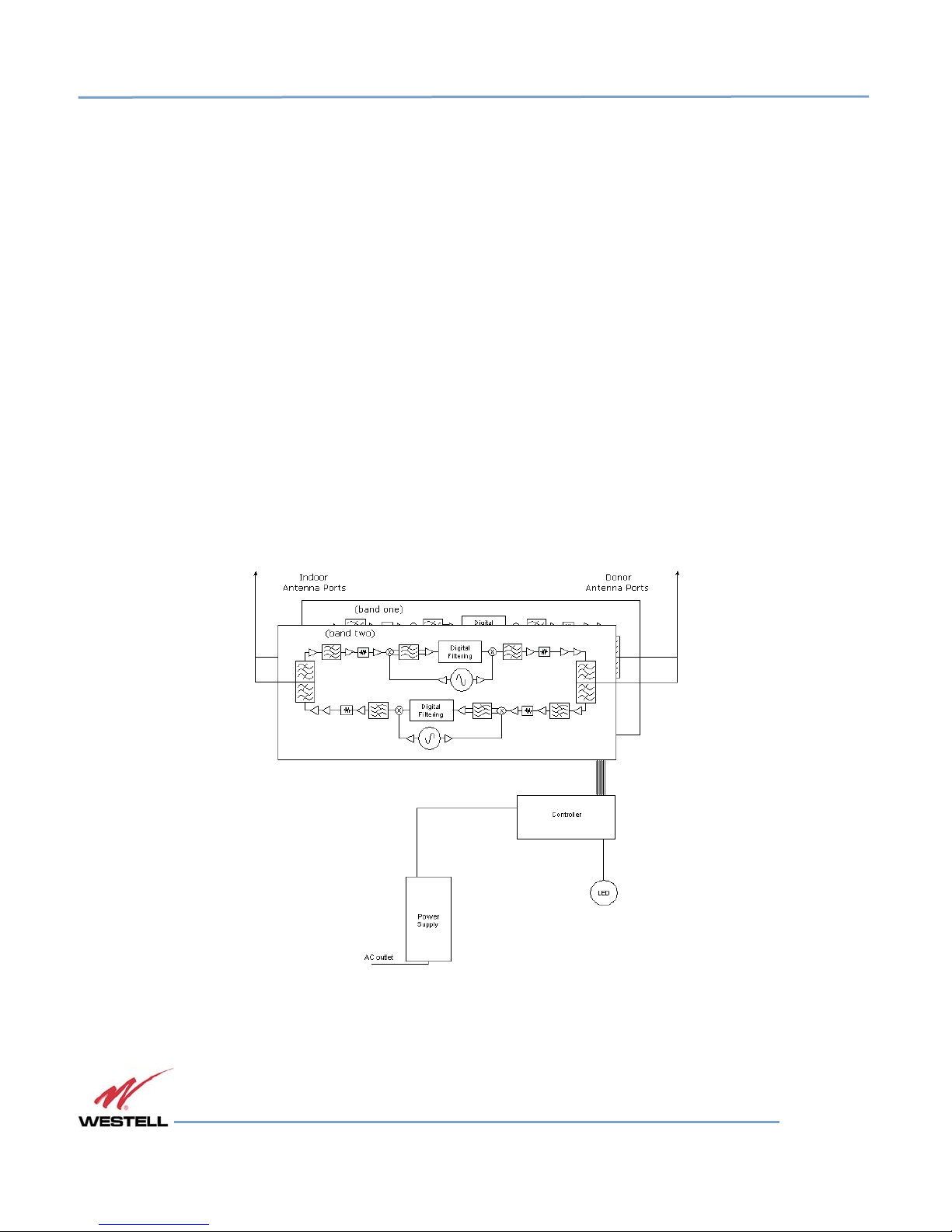
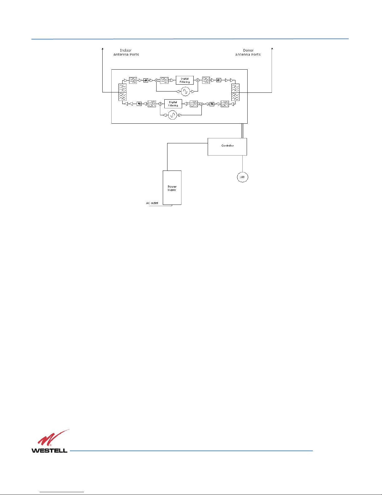
1.9 Circuit Operational Description
The
repeater
down-converting mixer.
then processes the resultant digitized IF signal that was
processed (filtered) digital signal
final power
(diplexer
independent manual
uses a single
amplifier
input to
down-conversion/up-conversion scheme.
The
down-converting mixers
is fed to a
digital-to-analog converter and then up-converted
make up the final gain stages before
diplexer output)
and
automatic gain controls
is
nominally
85 dB for either the
(AGC).
are
followed
There are
by a
single
multiple
IF
amplifier. A digital signal processor
previously generated
application
to the
downlink
diplexer.
or the uplink paths with both links having
RF
amplifier stages
by an
analog-to-digital converter.
to
RF. A driver amplifier
The
maximum
prior to each
total
system
block
The
and a
gain
AGC reacts to analog power
algorithm continuously monitors
system gain value, entered manually,
detection
these
is
on both the input and output of the uplink and downlink RF chains. A control
detected
optimally maintained without either exceeding
A/D converters.
The Status or
Power/Fault
LED will provide
immediate
repeater features automatic shutdown protection
oscillation condition occur. When
to a
normal, previously defined state,
the LED will be
illuminated green
in a
protected mode, a control algorithm determines
or
maintains
or
available
to be
1.10 Functional Block Diagrams
values and
dynamically
adjusts various gain stages such that the net
visual indication of the unit’s primary power alarm status. The
as a
safety measure should excessive drive
the
protection
reset.
The
until
events
manually reset.
that
trigger
the
FCC
parameters
be
applied
the
appropriate method
If
recovery
error
will be
saved
or
overdriving
to the
has been
in the
the
input
or an
of recovery
established,
event
log.
© 2015 Westell Technologies 9 September 2015 Doc. No. 960-1666-MNL rF
1.877.844.4274 Page 15 of 73
Figure 1-2: Dual Band Functional Block Diagram
WESTELL.COM
Digital Repeater Line
DSP85 Original Series plus Modular 250 and 251 Series
Figure 1-3: Single Band Functional Block Diagram
© 2015 Westell Technologies 9 September 2015 Doc. No. 960-1666-MNL rF
1.877.844.4274 Page 16 of 73
WESTELL.COM

Digital Repeater Line
DSP85 Original Series plus Modular 250 and 251 Series
2
System Optimization Installation
Tips
2.1 System Setup
All
cables should
leakage could cause oscillation
The rooftop antenna (donor antenna),
heading. Typically,
so. It is
before
If cables and alignment are
examine the signal
within
filtering
reoriented horizontally,
the
expensive
coverage
critical
the
the
system
the
frequency band(s)
or
attenuation might
interference
and possibly
to
these
from
Considerations
be
checked
the
directional antenna would
installer contact
is
turned
environment
outside signals
sites.
for
shorts
to
occur under some
if
the
service provider
on.
acceptable
in which the repeater is
can
cause
be
required
to
place
the
interference source
is so great that they
prohibitive measures.
and opens. V
directional, should
and a problem persists, it may be necessary to use a spectrum analyzer to
the AGC to
to
2.2 Suggested Spectrum Analyzer
When
troubleshooting
capable
of
connected
measuring the frequency that you are working with.
to a
source
RF issues, and
of RF
power such
surveying challenging
as the
erify that there
are no
cables
with
loose
conditions.
be
checked
be
aimed
at the
for
information
operating.
reduce
the
amplifier’s
reject these unwanted signals.
in an
antenna pattern
cannot
same
be
for
proper alignment along the calculated
site
that your handset uses,
on, and
filtered
The
gain or
approval
existence
of, the cell site he or she has
of strong adjacent channel signals
cause alarms.
In
some instances,
null.
There
or
otherwise reduced
also
In these cases it may not be practical to use the
Setting
RF
repeater
or a
environments,
An
attenuator should
powered
DAS.
it is
important
be
used
or
poor connections.
but it
may
not always be
In
some cases additional
the
donor antenna
may
be
some cases
or
eliminated
repeater
for providing
to have a spectrum
to
protect the
input
RF
compass
selected
can be
where
without
analyzer
when
Both uplink and downlink should be measured. Downlink should be measured on the donor cable and at the output
port of the powered up repeater, and uplink at the lead from the DAS (on
connect
be
Resolution bandwidth (RBW) should
the
whatever
If you
close-in-frequency signals.
to the
server
port on the
necessary
at
server antenna locations. The spectrum analyzer
closest available values should
is
appropriate.
cannot
see an
One
should
adjacent out-of-band signal
Be
sure
repeater)
and at the
donor
port with the
will
need
be set at 200 kHz for GSM and 1 MHz for CDMA. If you
be used. Video filter
also
make sure
that
should
there
be
about one-tenth
are no
signals above
when using the 1 MHz RBW
to set the
RBW back when
you
want
fiber-powered
repeater powered
to be
equipped
of RBW.
the top of the screen.
filter,
you can
to
measure
the
DAS, where the lead would
up.
Measurements may
with a whip
antenna
cannot select these
Other settings
decrease
power
level.
the RBW to see the
for this.
like span are
2.3 Important Installation Notes
Inadequate
feedback
normal operation
The
installer
selection
antennas near overhead power
will not
isolation between the outside and inside antennas may cause
can cause the
should refer to the Preface
and
installation.
come
in
contact
amplifier
of the cell
with
to emit a
continuous
site. Careful consideration
Safety Guidelines
To avo i d
those
serious
lines or high
components.
injury or death and
power components. Allow enough distance
signal at
of the
maximum amplitude
layout
and
damage
regenerative
feedback in the system. This
and, in some cases,
and
placement
of the
system
is imperative.
Important Safety Information
to the
repeater,
do not install donor or
so that if
antennas
interfere
for proper
should fall
(server)
also
values,
with
antenna
server
they
© 2015 Westell Technologies 9 September 2015 Doc. No. 960-1666-MNL rF
1.877.844.4274 Page 17 of 73
WESTELL.COM

Digital Repeater Line
DSP85 Original Series plus Modular 250 and 251 Series
Close
that
exceed
proximity to
FCC
the donor
limits
for
or
server antennas with the repeater
human
exposure.
in
WARNING
operation may expose the user
or
installer
to
RF
fields
Amplifier
or
or
handset damage may occur
the coax that
2.4 Installation Tips
2.4.1 Donor
When possible, shield the donor
Antenna
Accurately
service
Ensure
Mount
the RF signal from the
will be
feedback both
Normally mounting
determine the
provider/carrier.
that the
the
behind
radiation path
donor antenna
and
below
to and
from
the
donor
donor antenna higher
traffic metro areas avoid mounting the donor antenna any higher than necessary
may start
structures
to
become
are
behind
less
the
System components should
leads to the repeater.
azimuth
at or
the
the
stable
antenna relative
to the
to the
donor
toward
pass
the
above
donor antenna
service
antennas.
and it is
antenna’s
be
grounded
donor
cell site is as
edge
the
if
more likely
backside by locating it so that any HVAC units and/or penthouse
to the
in
accordance
if a
handset
cell
site. Obtain
is
connected directly
the
unobstructed
of the
roof,
in the
location(s)
of the
service antennas. Normally
viewed from above.
will
allow
a less
obstructed path
to
encounter adjacent channel
donor
cell site location.
with NEC
donor
as possible.
direction
This
approach
810-15,
to
the repeater
site
information
of the
donor site.
will help
to the
donor site. However,
as
the quality
interference.
21 as required.
and
approval from
Try t o
avoid
having
the
service
antennas
avoid interference
in high
of
the donor
signal
the
and
2.4.2 Antennas
Use
To av o id
omnidirectional antennas indoors,
minimize
and
signal
leakage
directionality would
to the
be
helpful
repeater uplink overload
subscribers frequently
use
their phones such
outside.
and RF
and gain
and locate them
Use
directional antennas indoors
exposure limits
limiting, mount
as
desks
centrally
will not be exceeded.
the
or
dispatch
with
respect
to the
only in special cases when
indoor antennas
areas.
intended coverage
away from areas
higher
where
area to
gain
mobile
To determine the quantity and locations of indoor antennas, use an appropriate phone’s signal meter to
determine areas of weak signals. These are the approximate areas where indoor antennas may be needed.
Be aware the signal from an indoor antenna, in most cases, can be expected to penetrate about two standard
office sheetrock-type walls to reach users. After two walls, or if the walls are made of other materials,
it may be necessary to split the available signal and add more antennas.
© 2015 Westell Technologies 9 September 2015 Doc. No. 960-1666-MNL rF
1.877.844.4274 Page 18 of 73
WESTELL.COM

Digital Repeater Line
DSP85 Original Series plus Modular 250 and 251 Series
2.5 Optional Accessories
A
complete line
Below are just a few
of
accessories
examples suitable
is
available from Westell. Check with your Westell distributor for any additional items needed.
for
most in-building
needs:
2.5.1 Outside Donor
PCS -
model number
Cellular - model number
Antenna
CSI-AY/1.85-1.99/10
2.5.2 Inside Omnidirectional
Quad-band - model number
2.5.3 Power
2:1 -
3:1 -
4:1 -
2.5.4 Grounding
Dividers
model number
model number
model number
Kit
Model number
ClearLink -SPD2/698-2.7K-LP/N
ClearLink -SPD3/698-2.7K-LP/N
ClearLink -SPD4/
CSI-GKIT
2.5.5 Lighting Arrestor
Model number
2.5.6 Directional
CSI-CAP
Couplers
CSI-AY/806-960/14
Antenna
ClearLink-O/698-2.7K/N
698-2.7K-LP/N
6 dB -
10 dB -
15 dB -
20 dB -
30 dB -
model number
model number
model number
model number
model number
ClearLink-DC6/698-2.7K/N
ClearLink -DC10/698-2.7K/N
ClearLink -DC15/698-2.7K/N
ClearLink -DC20/698-2.7K/N
ClearLink -DC30/698-2.7K/N
2.5.7 19” Rack Shelf
Model number CSI-RMS-250
2.5.8 UPS
Battery backup,
Battery backup,
© 2015 Westell Technologies 9 September 2015 Doc. No. 960-1666-MNL rF
1.877.844.4274 Page 19 of 73
two
hour single-band,
four
hour single-band,
one
hour dual-band - model number
two
hour dual-band - model number
CS48-985-600
CS48-985-601
WESTELL.COM

Digital Repeater Line
DSP85 Original Series plus Modular 250 and 251 Series
2.5.9 Cross Band Couplers
Quad-band Rack Mount - model number CSI-CM250-7/C/AW/P (700
LTE,
Cellular,
PCS and AWS)
Quad-band
Tri-band Rack Mount - model number CSI-CM250-U7C/C/P (700 Upper
Tri-ba nd
Tri-band Rack Mount - model number CSI-CM250-L7/C/P (700 Lower
Tri-ba nd
Wall
Mount - model number CSI-CBC/QUAD/N (700
Wall
Mount - model number CSI-CBC21/740-1990/N (700 Upper
Wall
Mount - model number CSI-CBC21/696-1990/N (700 Lower
LTE,
Cellular,
PCS and ASW)
C LTE,
Cellular
C LTE,
A/B/C LTE,
A/B/C LTE,
and PCS)
Cellular
Cellular
Cellular
and PCS)
and PCS)
and PCS)
© 2015 Westell Technologies 9 September 2015 Doc. No. 960-1666-MNL rF
1.877.844.4274 Page 20 of 73
WESTELL.COM
Digital Repeater Line
DSP85 Original Series plus Modular 250 and 251 Series
3 Web-based GUI
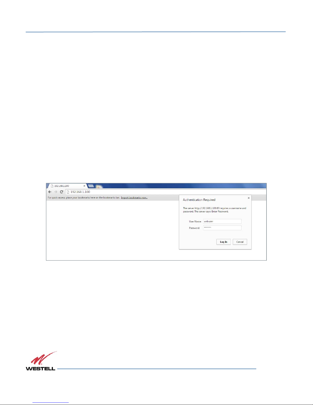
3.1 Web-based GUI Session
Primary access to the repeater is gained using a LAN connection and a Web
or Internet Explorer from Microsoft as shown in Figure 3-1. The repeater ships with the
192.168.1.100,
connecting
If
IP address of the
their computer
IP address as follows:
is
255.255.255.0. Questions pertaining
4.4 Additional Tips. When
purpose
but can be
changed
later if required.
directly to the repeater from a laptop or PC with a
repeater
to enable
into the
browser address
connection
line to
to a host that has a static IP.
192.168.1.x, where ‘x’ = any number from 2 to 254 inclusive other than 100. The subnet mask
of the GUI
session,
to these
connection
the
default user name
settings should
is made the user will be
is
webuser
crossover CAT-5E cable
connect. Most
Select
be
referred
prompted
and the
password
browser program
users will
need
such as
or
over a LAN, the user types the
to
update
Firefox
default
the
IP
TCP/IP settings
by
address
Mozilla,
on
Use the following IP Address and enter the
to the
user’s
IT
department
for a user name and
is
csi1234
as shown in
or refer to section
password.
Figure 3-1
For the
.
This
of
can be changed as required. Internet access is not required to use the GUI. If you are connecting using a laptop,
verify that your Ethernet port has power. Some laptops will not allow Ethernet connection when on battery power. If
this is the case with the laptop you are using you will need to plug it in or update the power settings. Please note the
GUI screens shown throughout this manual reflect a dual-band Cell/PCS configuration. They are for illustration
purposes only. The actual screen the user sees will depend on the variant involved.
© 2015 Westell Technologies 9 September 2015 Doc. No. 960-1666-MNL rF
1.877.844.4274 Page 21 of 73
Figure 3-1: User Connection Login
WESTELL.COM
Digital Repeater Line
DSP85 Original Series plus Modular 250 and 251 Series
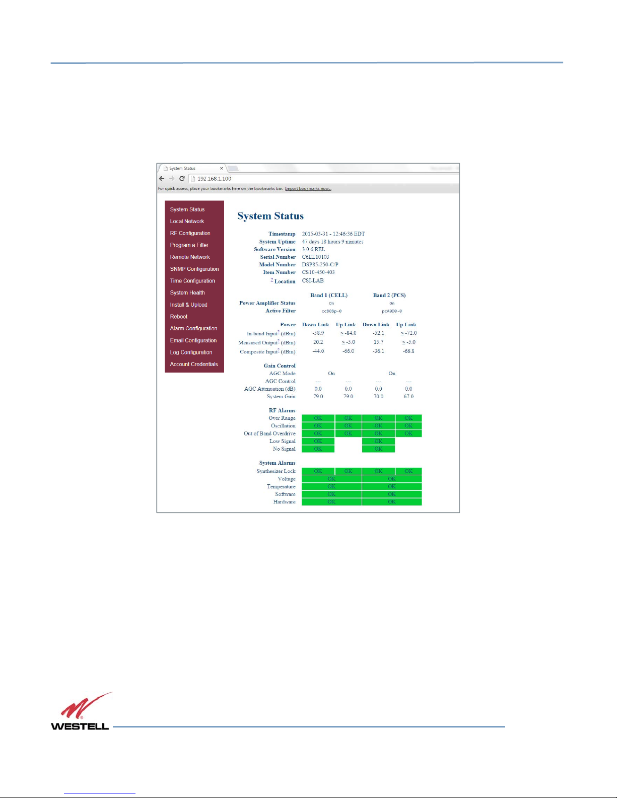
3.2 System
When
login is
Status
complete, the
System Status
page
is displayed, as shown in Figure 3-2. The Navigation Box on the left
hand side of the menu as shown in Figure 3-3 shows available operations. Selecting the operation will bring you to
the page for that operation
© 2015 Westell Technologies 9 September 2015 Doc. No. 960-1666-MNL rF
1.877.844.4274 Page 22 of 73
Figure 3-2: System Status
WESTELL.COM
 Loading...